Embed Size (px)
Citation preview
Deu
tsch
Sensor/Dimmaktor 1/1-fach; 2/1-fach
WARNUNG
Bei direktem oder indirektem Kontakt mit spannungsführenden Teilen kommt es zu einer gefährlichen Körperdurchströmung. Elektrischer Schock, Verbrennungen oder Tod können die Folge sein. Vor Montage und Demontage Netzspannung freischalten! Arbeiten am 230 V-Netz nur von Fachpersonal ausführen
lassen.
Montageanleitung sorgfältig lesen und aufbewahren. Weitere Benutzerinformationen unter
www.busch-jaeger.de/freeathome | www.abb.com/freeathomeoder durch Scannen des QR-Codes.
Informationen zur Systemeinbindung siehe Systemhandbuch (www.busch-jaeger.de/freeathome | www.abb.com/freeathome).
Bestimmungsgemäßer Gebrauch Der Dimmsensor bildet eine Einheit mit dem Universal-Dimmaktor. Dieser ist für die Ansteuerung und das Dimmen verschiedener Lasten bestimmt. Die Geräte sind entsprechend vorkonfiguriert. Nach Anschluss der Last kann diese direkt geschaltet/gedimmt werden (2/1-fach, über linke Wippe). Ausführliche Informationen zum Funktionsumfang siehe Technisches
Handbuch (siehe QR-Code).
Technische Daten Stromversorgung 24 VDC (erfolgt über Buslinie)
Busteilnehmer 1 (12mA)
Anschluss Busanschlussklemme: 0,4-0,8 mm Leitungstyp: J-Y(St)Y, 2x2x0,8 mm Abisolierung: 6-7 mm
Netzanschluss 230V ~, 50 / 60 Hz; Schraubklemmen: 2x2,5 mm2 starr; 2x1,5 mm2 flexibel
Nennlast R,L,C: 180 W/VA, LEDi: typ. 2-80 W/VA, CFL: 2-80 W/VA
Schutzart IP20
Umgebungstemperatur - 5 °C – + 45 °C
Lagertemperatur - 20 °C – + 70 °C
Lastarten
optimiert für Retrofit‐LED‐Leuchtmittel (LEDi). Erweiterte Referenzliste: www.busch-jaeger.de/freeathome | www.abb.com/freeathome.
Montage Einbau nur in Unterputzdosen, die sich in trockenen Innenräumen
befinden. Dabei die geltenden Vorschriften beachten.
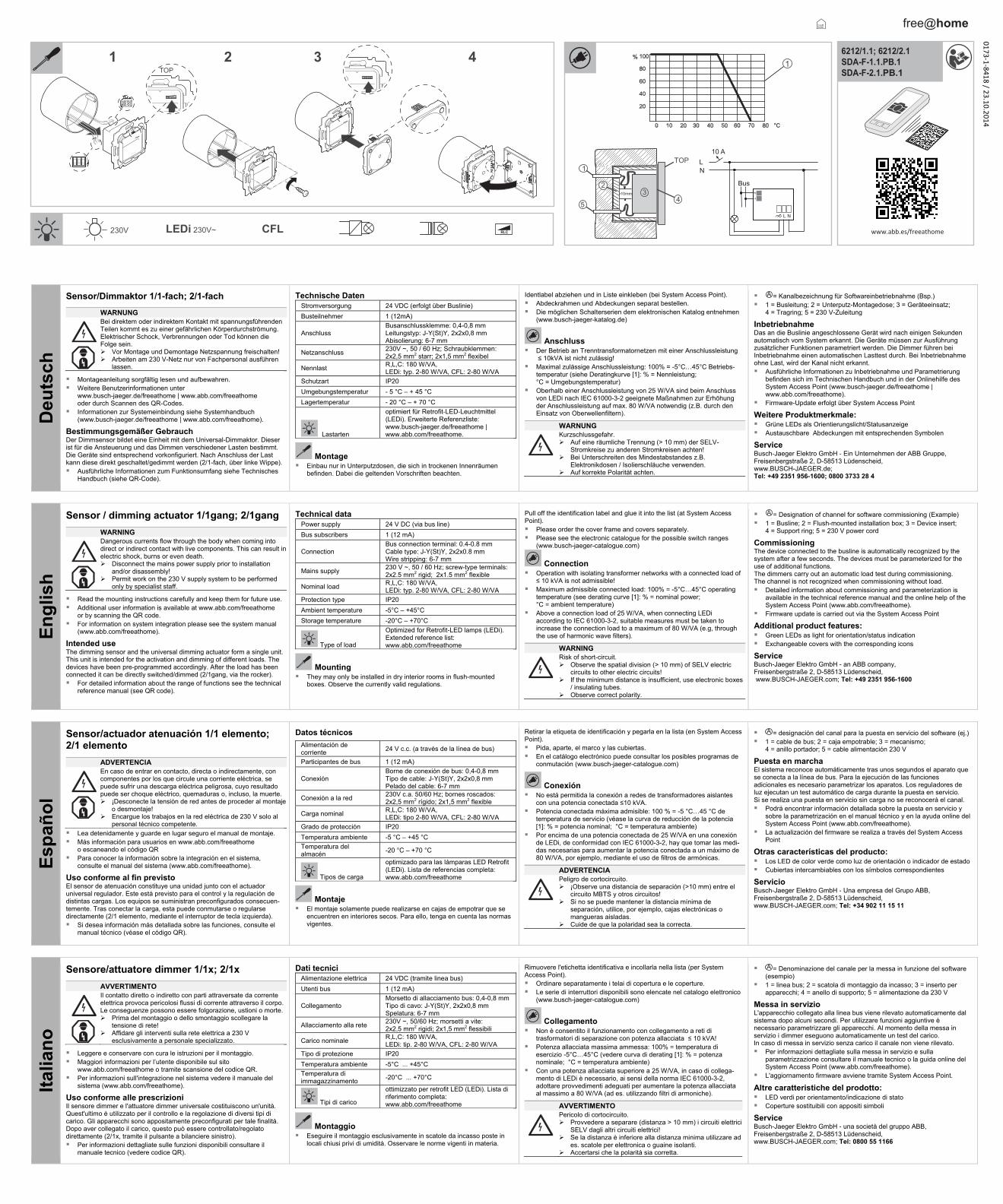
Identlabel abziehen und in Liste einkleben (bei System Access Point). Abdeckrahmen und Abdeckungen separat bestellen. Die möglichen Schalterserien dem elektronischen Katalog entnehmen
(www.busch-jaeger-katalog.de)
Anschluss Der Betrieb an Trenntransformatornetzen mit einer Anschlussleistung
≤ 10kVA ist nicht zulässig! Maximal zulässige Anschlussleistung: 100% = -5°C…45°C Betriebs-
temperatur (siehe Deratingkurve [1]: % = Nennleistung; °C = Umgebungstemperatur)
Oberhalb einer Anschlussleistung von 25 W/VA sind beim Anschluss von LEDi nach IEC 61000-3-2 geeignete Maßnahmen zur Erhöhung der Anschlussleistung auf max. 80 W/VA notwendig (z.B. durch den Einsatz von Oberwellenfiltern).
WARNUNG Kurzschlussgefahr. Auf eine räumliche Trennung (> 10 mm) der SELV-
Stromkreise zu anderen Stromkreisen achten! Bei Unterschreiten des Mindestabstandes z.B.
Elektronikdosen / Isolierschläuche verwenden. Auf korrekte Polarität achten.
= Kanalbezeichnung für Softwareinbetriebnahme (Bsp.) 1 = Busleitung; 2 = Unterputz-Montagedose; 3 = Geräteeinsatz;
4 = Tragring; 5 = 230 V-Zuleitung
Inbetriebnahme Das an die Buslinie angeschlossene Gerät wird nach einigen Sekunden automatisch vom System erkannt. Die Geräte müssen zur Ausführung zusätzlicher Funktionen parametriert werden. Die Dimmer führen bei Inbetriebnahme einen automatischen Lasttest durch. Bei Inbetriebnahme ohne Last, wird der Kanal nicht erkannt. Ausführliche Informationen zu Inbetriebnahme und Parametrierung
befinden sich im Technischen Handbuch und in der Onlinehilfe des System Access Point (www.busch-jaeger.de/freeathome | www.abb.com/freeathome).
Firmware-Update erfolgt über System Access Point
Weitere Produktmerkmale: Grüne LEDs als Orientierungslicht/Statusanzeige Austauschbare Abdeckungen mit entsprechenden Symbolen
Service Busch‐Jaeger Elektro GmbH ‐ Ein Unternehmen der ABB Gruppe, Freisenbergstraße 2, D-58513 Lüdenscheid, www.BUSCH-JAEGER.de; Tel: +49 2351 956-1600; 0800 3733 28 4
En
glis
h
Sensor / dimming actuator 1/1gang; 2/1gang
WARNING
Dangerous currents flow through the body when coming into direct or indirect contact with live components. This can result in electric shock, burns or even death. Disconnect the mains power supply prior to installation
and/or disassembly! Permit work on the 230 V supply system to be performed
only by specialist staff.
Read the mounting instructions carefully and keep them for future use. Additional user information is available at www.abb.com/freeathome
or by scanning the QR code. For information on system integration please see the system manual
(www.abb.com/freeathome).
Intended use The dimming sensor and the universal dimming actuator form a single unit. This unit is intended for the activation and dimming of different loads. The devices have been pre-programmed accordingly. After the load has been connected it can be directly switched/dimmed (2/1gang, via the rocker). For detailed information about the range of functions see the technical
reference manual (see QR code).
Technical data Power supply 24 V DC (via bus line)
Bus subscribers 1 (12 mA)
Connection Bus connection terminal: 0.4-0.8 mm Cable type: J-Y(St)Y, 2x2x0.8 mm Wire stripping: 6-7 mm
Mains supply 230 V ~, 50 / 60 Hz; screw-type terminals: 2x2.5 mm2 rigid; 2x1.5 mm2 flexible
Nominal load R,L,C: 180 W/VA, LEDi: typ. 2-80 W/VA, CFL: 2-80 W/VA
Protection type IP20
Ambient temperature -5°C – +45°C
Storage temperature -20°C – +70°C
Type of load
Optimized for Retrofit‐LED lamps (LEDi). Extended reference list: www.abb.com/freeathome
Mounting They may only be installed in dry interior rooms in flush-mounted
boxes. Observe the currently valid regulations.
Pull off the identification label and glue it into the list (at System Access Point). Please order the cover frame and covers separately. Please see the electronic catalogue for the possible switch ranges
(www.busch-jaeger-catalogue.com)
Connection Operation with isolating transformer networks with a connected load of
≤ 10 kVA is not admissible! Maximum admissible connected load: 100% = -5°C…45°C operating
temperature (see derating curve [1]: % = nominal power; °C = ambient temperature)
Above a connection load of 25 W/VA, when connecting LEDi according to IEC 61000-3-2, suitable measures must be taken to increase the connection load to a maximum of 80 W/VA (e.g, through the use of harmonic wave filters).
WARNING Risk of short-circuit. Observe the spatial division (> 10 mm) of SELV electric
circuits to other electric circuits! If the minimum distance is insufficient, use electronic boxes
/ insulating tubes. Observe correct polarity.
= Designation of channel for software commissioning (Example) 1 = Busline; 2 = Flush-mounted installation box; 3 = Device insert;
4 = Support ring; 5 = 230 V power cord
Commissioning The device connected to the busline is automatically recognized by the system after a few seconds. The devices must be parameterized for the use of additional functions. The dimmers carry out an automatic load test during commissioning. The channel is not recognized when commissioning without load. Detailed information about commissioning and parameterization is
available in the technical reference manual and the online help of the System Access Point (www.abb.com/freeathome).
Firmware update is carried out via the System Access Point
Additional product features: Green LEDs as light for orientation/status indication Exchangeable covers with the corresponding icons
Service Busch-Jaeger Elektro GmbH - an ABB company, Freisenbergstraße 2, D-58513 Lüdenscheid, www.BUSCH-JAEGER.com; Tel: +49 2351 956-1600
Esp
año
l
Sensor/actuador atenuación 1/1 elemento; 2/1 elemento
ADVERTENCIA
En caso de entrar en contacto, directa o indirectamente, con componentes por los que circule una corriente eléctrica, se puede sufrir una descarga eléctrica peligrosa, cuyo resultado puede ser choque eléctrico, quemaduras o, incluso, la muerte. ¡Desconecte la tensión de red antes de proceder al montaje
o desmontaje! Encargue los trabajos en la red eléctrica de 230 V solo al
personal técnico competente.
Lea detenidamente y guarde en lugar seguro el manual de montaje. Más información para usuarios en www.abb.com/freeathome
o escaneando el código QR Para conocer la información sobre la integración en el sistema,
consulte el manual del sistema (www.abb.com/freeathome).
Uso conforme al fin previsto El sensor de atenuación constituye una unidad junto con el actuador universal regulador. Este está previsto para el control y la regulación de distintas cargas. Los equipos se suministran preconfigurados consecuen-temente. Tras conectar la carga, esta puede conmutarse o regularse directamente (2/1 elemento, mediante el interruptor de tecla izquierda). Si desea información más detallada sobre las funciones, consulte el
manual técnico (véase el código QR).
Datos técnicos
Alimentación de corriente
24 V c.c. (a través de la línea de bus)
Participantes de bus 1 (12 mA)
Conexión Borne de conexión de bus: 0,4-0,8 mm Tipo de cable: J-Y(St)Y, 2x2x0,8 mm Pelado del cable: 6-7 mm
Conexión a la red 230V c.a. 50/60 Hz; bornes roscados: 2x2,5 mm2 rígido; 2x1,5 mm2 flexible
Carga nominal R,L,C: 180 W/VA, LEDi: tipo 2-80 W/VA, CFL: 2-80 W/VA
Grado de protección IP20
Temperatura ambiente -5 °C – +45 °C
Temperatura del almacén
-20 °C – +70 °C
Tipos de carga
optimizado para las lámparas LED Retrofit (LEDi). Lista de referencias completa: www.abb.com/freeathome
Montaje El montaje solamente puede realizarse en cajas de empotrar que se
encuentren en interiores secos. Para ello, tenga en cuenta las normas vigentes.
Retirar la etiqueta de identificación y pegarla en la lista (en System Access Point). Pida, aparte, el marco y las cubiertas. En el catálogo electrónico puede consultar los posibles programas de
conmutación (www.busch-jaeger-catalogue.com)
Conexión No está permitida la conexión a redes de transformadores aislantes
con una potencia conectada ≤10 kVA. Potencia conectada máxima admisible: 100 % = -5 °C…45 °C de
temperatura de servicio (véase la curva de reducción de la potencia [1]: % = potencia nominal; °C = temperatura ambiente)
Por encima de una potencia conectada de 25 W/VA en una conexión de LEDi, de conformidad con IEC 61000-3-2, hay que tomar las medi-das necesarias para aumentar la potencia conectada a un máximo de 80 W/VA, por ejemplo, mediante el uso de filtros de armónicas.
ADVERTENCIA Peligro de cortocircuito. ¡Observe una distancia de separación (>10 mm) entre el
circuito MBTS y otros circuitos! Si no se puede mantener la distancia mínima de
separación, utilice, por ejemplo, cajas electrónicas o mangueras aisladas.
Cuide de que la polaridad sea la correcta.
= designación del canal para la puesta en servicio del software (ej.) 1 = cable de bus; 2 = caja empotrable; 3 = mecanismo;
4 = anillo portador; 5 = cable alimentación 230 V
Puesta en marcha El sistema reconoce automáticamente tras unos segundos el aparato que se conecta a la línea de bus. Para la ejecución de las funciones adicionales es necesario parametrizar los aparatos. Los reguladores de luz ejecutan un test automático de carga durante la puesta en servicio. Si se realiza una puesta en servicio sin carga no se reconocerá el canal. Podrá encontrar información detallada sobre la puesta en servicio y
sobre la parametrización en el manual técnico y en la ayuda online del System Access Point (www.abb.com/freeathome).
La actualización del firmware se realiza a través del System Access Point
Otras características del producto: Los LED de color verde como luz de orientación o indicador de estado Cubiertas intercambiables con los símbolos correspondientes
Servicio Busch‐Jaeger Elektro GmbH ‐ Una empresa del Grupo ABB, Freisenbergstraße 2, D-58513 Lüdenscheid, www.BUSCH-JAEGER.com; Tel: +34 902 11 15 11
Ital
ian
o
Sensore/attuatore dimmer 1/1x; 2/1x
AVVERTIMENTO
Il contatto diretto o indiretto con parti attraversate da corrente elettrica provoca pericolosi flussi di corrente attraverso il corpo. Le conseguenze possono essere folgorazione, ustioni o morte. Prima del montaggio o dello smontaggio scollegare la
tensione di rete! Affidare gli interventi sulla rete elettrica a 230 V
esclusivamente a personale specializzato.
Leggere e conservare con cura le istruzioni per il montaggio. Maggiori informazioni per l’utente disponibile sul sito
www.abb.com/freeathome o tramite scansione del codice QR. Per informazioni sull'integrazione nel sistema vedere il manuale del
sistema (www.abb.com/freeathome).
Uso conforme alle prescrizioni Il sensore dimmer e l'attuatore dimmer universale costituiscono un'unità. Quest'ultimo è utilizzato per il controllo e la regolazione di diversi tipi di carico. Gli apparecchi sono appositamente preconfigurati per tale finalità. Dopo aver collegato il carico, questo può essere controllato/regolato direttamente (2/1x, tramite il pulsante a bilanciere sinistro). Per informazioni dettagliate sulle funzioni disponibili consultare il
manuale tecnico (vedere codice QR).
Dati tecnici Alimentazione elettrica 24 VDC (tramite linea bus)
Utenti bus 1 (12 mA)
Collegamento Morsetto di allacciamento bus: 0,4-0,8 mm Tipo di cavo: J-Y(St)Y, 2x2x0,8 mm Spelatura: 6-7 mm
Allacciamento alla rete 230V ~, 50/60 Hz; morsetti a vite: 2x2,5 mm2 rigidi; 2x1,5 mm2 flessibili
Carico nominale R,L,C: 180 W/VA, LEDi: tip. 2-80 W/VA, CFL: 2-80 W/VA
Tipo di protezione IP20
Temperatura ambiente -5°C ... +45°C
Temperatura di immagazzinamento
-20°C ... +70°C
Tipi di carico
ottimizzato per retrofit LED (LEDi). Lista di riferimento completa: www.abb.com/freeathome
Montaggio Eseguire il montaggio esclusivamente in scatole da incasso poste in
locali chiusi privi di umidità. Osservare le norme vigenti in materia.
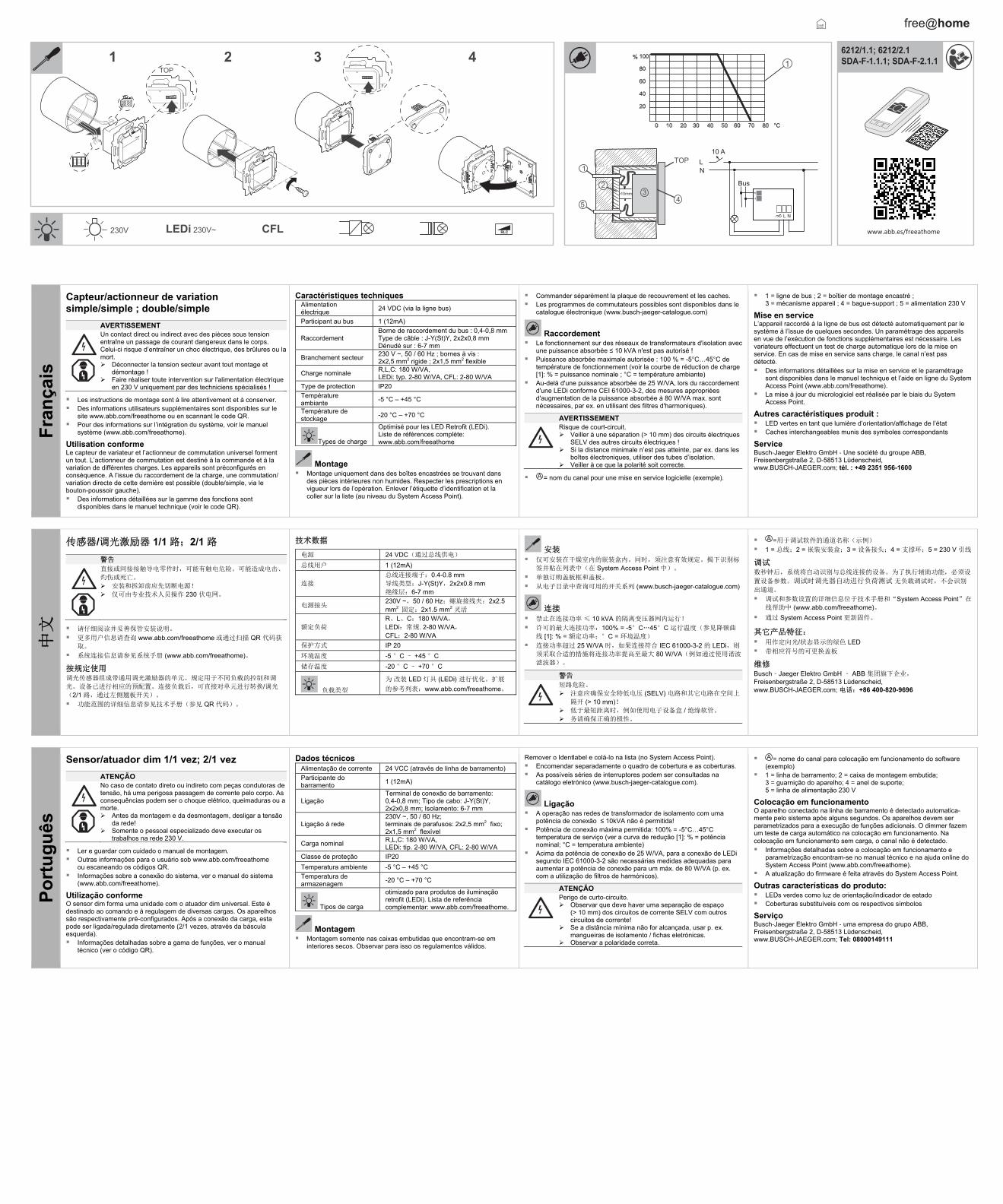
Rimuovere l'etichetta identificativa e incollarla nella lista (per System Access Point). Ordinare separatamente i telai di copertura e le coperture. Le serie di interruttori disponibili sono elencate nel catalogo elettronico
(www.busch-jaeger-catalogue.com)
Collegamento Non è consentito il funzionamento con collegamento a reti di
trasformatori di separazione con potenza allacciata ≤ 10 kVA! Potenza allacciata massima ammessa: 100% = temperatura di
esercizio -5°C…45°C (vedere curva di derating [1]: % = potenza nominale; °C = temperatura ambiente)
Con una potenza allacciata superiore a 25 W/VA, in caso di collega-mento di LEDi è necessario, ai sensi della norma IEC 61000-3-2, adottare provvedimenti adeguati per aumentare la potenza allacciata al massimo a 80 W/VA (ad es. utilizzando filtri di armoniche).
AVVERTIMENTO Pericolo di cortocircuito. Provvedere a separare (distanza > 10 mm) i circuiti elettrici
SELV dagli altri circuiti elettrici! Se la distanza è inferiore alla distanza minima utilizzare ad
es. scatole per elettronica o guaine isolanti. Accertarsi che la polarità sia corretta.
= Denominazione del canale per la messa in funzione del software (esempio)
1 = linea bus; 2 = scatola di montaggio da incasso; 3 = inserto per apparecchi; 4 = anello di supporto; 5 = alimentazione da 230 V
Messa in servizio L'apparecchio collegato alla linea bus viene rilevato automaticamente dal sistema dopo alcuni secondi. Per utilizzare funzioni aggiuntive è necessario parametrizzare gli apparecchi. Al momento della messa in servizio i dimmer eseguono automaticamente un test del carico. In caso di messa in servizio senza carico il canale non viene rilevato. Per informazioni dettagliate sulla messa in servizio e sulla
parametrizzazione consultare il manuale tecnico o la guida online del System Access Point (www.abb.com/freeathome).
L'aggiornamento firmware avviene tramite System Access Point.
Altre caratteristiche del prodotto: LED verdi per orientamento/indicazione di stato Coperture sostituibili con appositi simboli
Service Busch‐Jaeger Elektro GmbH ‐ una società del gruppo ABB, Freisenbergstraße 2, D-58513 Lüdenscheid, www.BUSCH-JAEGER.com; Tel: 0800 55 1166
1 2 43 6212/1.1; 6212/2.1SDA-F-1.1.PB.1 SDA-F-2.1.PB.1
www.abb.es/freeathome
TOP
>
1
34
5
2
1
230V LEDi 230V~ CFL
free@home
10mm
TOP
Bus
LN
+-
10 A
NL
0173-1-8418 / 23.10.2014
Fra
nça
is
Capteur/actionneur de variation simple/simple ; double/simple
AVERTISSEMENT
Un contact direct ou indirect avec des pièces sous tension entraîne un passage de courant dangereux dans le corps. Celui-ci risque d’entraîner un choc électrique, des brûlures ou la mort. Déconnecter la tension secteur avant tout montage et
démontage ! Faire réaliser toute intervention sur l'alimentation électrique
en 230 V uniquement par des techniciens spécialisés !
Les instructions de montage sont à lire attentivement et à conserver. Des informations utilisateurs supplémentaires sont disponibles sur le
site www.abb.com/freeathome ou en scannant le code QR. Pour des informations sur l’intégration du système, voir le manuel
système (www.abb.com/freeathome).
Utilisation conforme Le capteur de variateur et l’actionneur de commutation universel forment un tout. L’actionneur de commutation est destiné à la commande et à la variation de différentes charges. Les appareils sont préconfigurés en conséquence. A l’issue du raccordement de la charge, une commutation/ variation directe de cette dernière est possible (double/simple, via le bouton-poussoir gauche). Des informations détaillées sur la gamme des fonctions sont
disponibles dans le manuel technique (voir le code QR).
Caractéristiques techniques Alimentation électrique
24 VDC (via la ligne bus)
Participant au bus 1 (12mA)
Raccordement Borne de raccordement du bus : 0,4-0,8 mm Type de câble : J-Y(St)Y, 2x2x0,8 mm Dénudé sur : 6-7 mm
Branchement secteur 230 V ~, 50 / 60 Hz ; bornes à vis : 2x2,5 mm2 rigide ; 2x1,5 mm2 flexible
Charge nominale R,L,C: 180 W/VA, LEDi: typ. 2-80 W/VA, CFL: 2-80 W/VA
Type de protection IP20
Température ambiante
-5 °C – +45 °C
Température de stockage
-20 °C – +70 °C
Types de charge
Optimisé pour les LED Retrofit (LEDi). Liste de références complète: www.abb.com/freeathome
Montage Montage uniquement dans des boîtes encastrées se trouvant dans
des pièces intérieures non humides. Respecter les prescriptions en vigueur lors de l’opération. Enlever l’étiquette d’identification et la coller sur la liste (au niveau du System Access Point).
Commander séparément la plaque de recouvrement et les caches. Les programmes de commutateurs possibles sont disponibles dans le
catalogue électronique (www.busch-jaeger-catalogue.com)
Raccordement Le fonctionnement sur des réseaux de transformateurs d'isolation avec
une puissance absorbée ≤ 10 kVA n'est pas autorisé ! Puissance absorbée maximale autorisée : 100 % = -5°C…45°C de
température de fonctionnement (voir la courbe de réduction de charge [1]: % = puissance nominale ; °C = température ambiante)
Au-delà d'une puissance absorbée de 25 W/VA, lors du raccordement d'une LEDi conforme CEI 61000-3-2, des mesures appropriées d'augmentation de la puissance absorbée à 80 W/VA max. sont nécessaires, par ex. en utilisant des filtres d'harmoniques).
AVERTISSEMENT Risque de court-circuit. Veiller à une séparation (> 10 mm) des circuits électriques
SELV des autres circuits électriques ! Si la distance minimale n’est pas atteinte, par ex. dans les
boîtes électroniques, utiliser des tubes d’isolation. Veiller à ce que la polarité soit correcte.
= nom du canal pour une mise en service logicielle (exemple).
1 = ligne de bus ; 2 = boîtier de montage encastré ; 3 = mécanisme appareil ; 4 = bague-support ; 5 = alimentation 230 V
Mise en service L’appareil raccordé à la ligne de bus est détecté automatiquement par le système à l’issue de quelques secondes. Un paramétrage des appareils en vue de l’exécution de fonctions supplémentaires est nécessaire. Les variateurs effectuent un test de charge automatique lors de la mise en service. En cas de mise en service sans charge, le canal n’est pas détecté. Des informations détaillées sur la mise en service et le paramétrage
sont disponibles dans le manuel technique et l’aide en ligne du System Access Point (www.abb.com/freeathome).
La mise à jour du micrologiciel est réalisée par le biais du System Access Point.
Autres caractéristiques produit : LED vertes en tant que lumière d’orientation/affichage de l’état Caches interchangeables munis des symboles correspondants
Service Busch‐Jaeger Elektro GmbH ‐ Une société du groupe ABB, Freisenbergstraße 2, D-58513 Lüdenscheid, www.BUSCH-JAEGER.com; tél. : +49 2351 956-1600
中文
传感器/调光激励器 1/1 路;2/1 路
警告 直接或间接接触导电零件时,可能有触电危险。可能造成电击、
灼伤或死亡。 安装和拆卸前应先切断电源!
仅可由专业技术人员操作 230 伏电网。
请仔细阅读并妥善保管安装说明。
更多用户信息请查询 www.abb.com/freeathome 或通过扫描 QR 代码获
取。
系统连接信息请参见系统手册 (www.abb.com/freeathome)。
按规定使用调光传感器组成带通用调光激励器的单元。规定用于不同负载的控制和调
光。设备已进行相应的预配置。连接负载后,可直接对单元进行转换/调光
(2/1 路,通过左侧翘板开关)。
功能范围的详细信息请参见技术手册(参见 QR 代码)。
技术数据
电源 24 VDC(通过总线供电)
总线用户 1 (12mA)
连接
总线连接端子:0.4-0.8 mm 导线类型:J-Y(St)Y,2x2x0.8 mm 绝缘层:6-7 mm
电源接头230V ~,50 / 60 Hz;螺旋接线夹:2x2.5 mm2 固定;2x1.5 mm2 灵活
额定负荷
R、L、C:180 W/VA, LEDi:常规. 2-80 W/VA, CFL:2-80 W/VA
保护方式 IP 20
环境温度 -5 °C – +45 °C
储存温度 -20 °C – +70 °C
负载类型
为 改装 LED 灯具 (LEDi) 进行优化。扩展
的参考列表:www.abb.com/freeathome。
安装 仅可安装在干燥室内的嵌装盒内。同时,须注意有效规定。揭下识别标
签并贴在列表中(在 System Access Point 中)。
单独订购盖板框和盖板。
从电子目录中查询可用的开关系列 (www.busch-jaeger-catalogue.com)
连接 禁止在连接功率 ≤ 10 kVA 的隔离变压器网内运行!
许可的最大连接功率:100% = -5°C…45°C 运行温度(参见降额曲
线 [1]: % = 额定功率;°C = 环境温度)
连接功率超过 25 W/VA 时,如果连接符合 IEC 61000-3-2 的 LEDi,则
须采取合适的措施将连接功率提高至最大 80 W/VA(例如通过使用谐波
滤波器)。
警告
短路危险。
注意应确保安全特低电压 (SELV) 电路和其它电路在空间上
隔开 (> 10 mm)! 低于最短距离时,例如使用电子设备盒 / 绝缘软管。
务请确保正确的极性。
=用于调试软件的通道名称(示例)
1 = 总线;2 = 嵌装安装盒;3 = 设备接头;4 = 支撑环;5 = 230 V 引线
调试数秒钟后,系统将自动识别与总线连接的设备。为了执行辅助功能,必须设
置设备参数。调试时调光器自动进行负荷测试 无负载调试时,不会识别
出通道。 调试和参数设置的详细信息位于技术手册和“System Access Point”在
线帮助中 (www.abb.com/freeathome)。
通过 System Access Point 更新固件。
其它产品特征: 用作定向光/状态显示的绿色 LED
带相应符号的可更换盖板
维修 Busch‐Jaeger Elektro GmbH ‐ ABB 集团旗下企业, Freisenbergstraße 2, D-58513 Lüdenscheid, www.BUSCH-JAEGER.com; 电话:+86 400-820-9696
Po
rtu
gu
ês
Sensor/atuador dim 1/1 vez; 2/1 vez
ATENÇÃO
No caso de contato direto ou indireto com peças condutoras de tensão, há uma perigosa passagem de corrente pelo corpo. As consequências podem ser o choque elétrico, queimaduras ou a morte. Antes da montagem e da desmontagem, desligar a tensão
da rede! Somente o pessoal especializado deve executar os
trabalhos na rede 230 V.
Ler e guardar com cuidado o manual de montagem. Outras informações para o usuário sob www.abb.com/freeathome
ou escaneando os códigos QR. Informações sobre a conexão do sistema, ver o manual do sistema
(www.abb.com/freeathome).
Utilização conforme O sensor dim forma uma unidade com o atuador dim universal. Este é destinado ao comando e à regulagem de diversas cargas. Os aparelhos são respectivamente pré-configurados. Após a conexão da carga, esta pode ser ligada/regulada diretamente (2/1 vezes, através da báscula esquerda). Informações detalhadas sobre a gama de funções, ver o manual
técnico (ver o código QR).
Dados técnicos Alimentação de corrente 24 VCC (através de linha de barramento)
Participante do barramento
1 (12mA)
Ligação Terminal de conexão de barramento: 0,4-0,8 mm; Tipo de cabo: J-Y(St)Y, 2x2x0,8 mm; Isolamento: 6-7 mm
Ligação à rede 230V ~, 50 / 60 Hz; terminais de parafusos: 2x2,5 mm2 fixo; 2x1,5 mm2 flexível
Carga nominal R,L,C: 180 W/VA, LEDi: típ. 2-80 W/VA, CFL: 2-80 W/VA
Classe de proteção IP20
Temperatura ambiente -5 °C – +45 °C
Temperatura de armazenagem
-20 °C – +70 °C
Tipos de carga
otimizado para produtos de iluminação retrofit (LEDi). Lista de referência complementar: www.abb.com/freeathome.
Montagem Montagem somente nas caixas embutidas que encontram-se em
interiores secos. Observar para isso os regulamentos válidos.
Remover o Identlabel e colá-lo na lista (no System Access Point). Encomendar separadamente o quadro de cobertura e as coberturas. As possíveis séries de interruptores podem ser consultadas na
catálogo eletrónico (www.busch-jaeger-catalogue.com).
Ligação A operação nas redes de transformador de isolamento com uma
potência de conexão ≤ 10kVA não é permitida! Potência de conexão máxima permitida: 100% = -5°C…45°C
temperatura de serviço (ver a curva de redução [1]: % = potência nominal; °C = temperatura ambiente)
Acima da potência de conexão de 25 W/VA, para a conexão de LEDi segundo IEC 61000-3-2 são necessárias medidas adequadas para aumentar a potência de conexão para um máx. de 80 W/VA (p. ex. com a utilização de filtros de harmónicos).
ATENÇÃO Perigo de curto-circuito. Observar que deve haver uma separação de espaço
(> 10 mm) dos circuitos de corrente SELV com outros circuitos de corrente!
Se a distância mínima não for alcançada, usar p. ex. mangueiras de isolamento / fichas eletrónicas.
Observar a polaridade correta.
= nome do canal para colocação em funcionamento do software (exemplo)
1 = linha de barramento; 2 = caixa de montagem embutida;3 = guarnição do aparelho; 4 = anel de suporte; 5 = linha de alimentação 230 V
Colocação em funcionamento O aparelho conectado na linha de barramento é detectado automatica-mente pelo sistema após alguns segundos. Os aparelhos devem ser parametrizados para a execução de funções adicionais. O dimmer fazem um teste de carga automático na colocação em funcionamento. Na colocação em funcionamento sem carga, o canal não é detectado. Informações detalhadas sobre a colocação em funcionamento e
parametrização encontram-se no manual técnico e na ajuda online doSystem Access Point (www.abb.com/freeathome).
A atualização do firmware é feita através do System Access Point.
Outras características do produto: LEDs verdes como luz de orientação/indicador de estado Coberturas substituíveis com os respectivos símbolos
Serviço Busch‐Jaeger Elektro GmbH ‐ uma empresa do grupo ABB, Freisenbergstraße 2, D-58513 Lüdenscheid, www.BUSCH-JAEGER.com; Tel: 08000149111
1 2 43 6212/1.1; 6212/2.1SDA-F-1.1.1; SDA-F-2.1.1
www.abb.es/freeathome
TOP
>
1
34
5
2
1
230V LEDi 230V~ CFL
free@home
10mm
TOP
Bus
LN
+-
10 A
NL