Embed Size (px)
Citation preview

Edition 2012 Rev.0
Willkommen bei voestalpine Giesserei Linz GmbHWelcome to voestalpine Giesserei Linz GmbH
Die voestalpine Giesserei Linz GmbH ist ein weltweit führendes Unternehmen in der Herstellung von wartungsfreien
Gleitelementen WF 750 und ist auche führender Hersteller von Kompaktschieber, deren Haupteinsatzgebiet
in der Automobilindustrie liegt.
The metal foundry of voestalpine Giesserei Linz GmbH is an internationally recongnized supplier of maintenance-free,
self-lubricatiing sliding elements - WF 750 - which are mainly used in stamping dies for the automotive, plastic machine
and tooling and other industries.
Edition 2012 Rev. 0
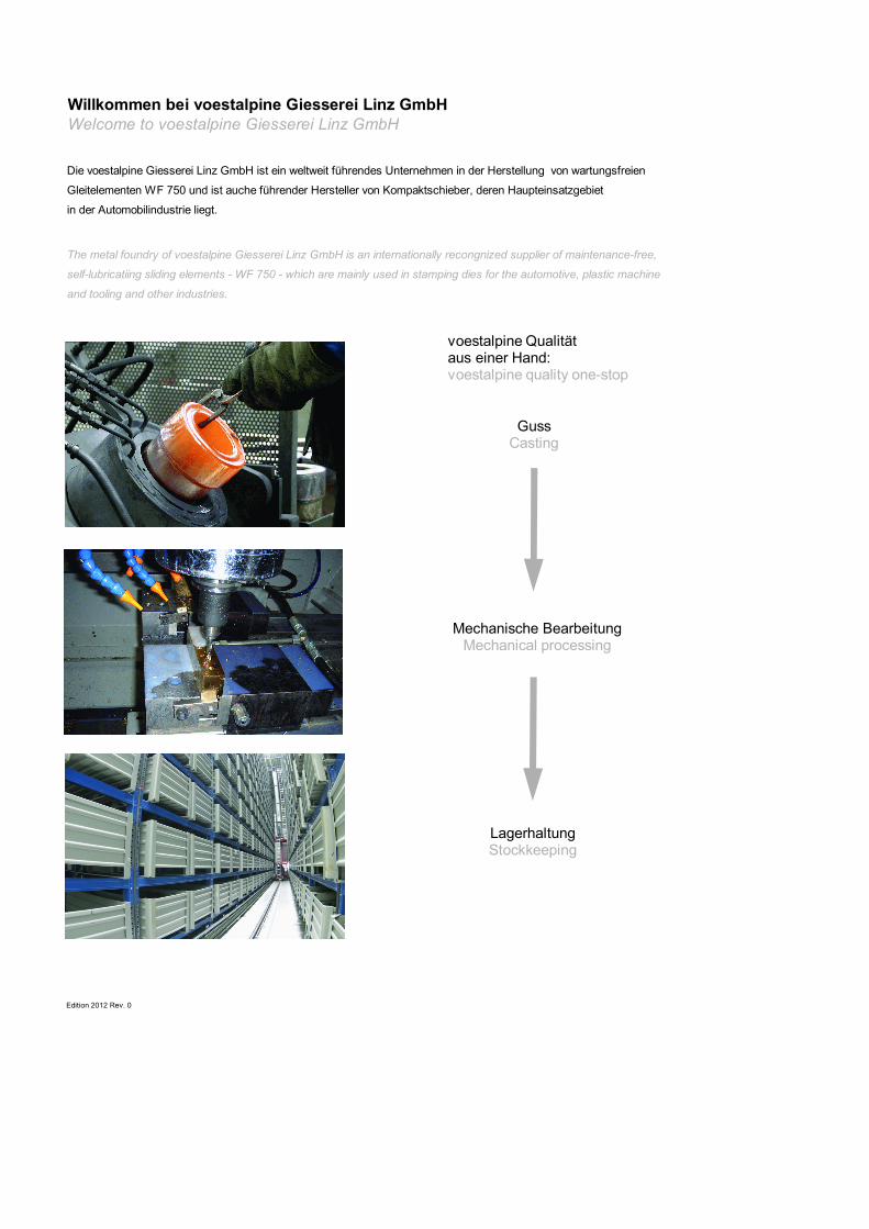
voestalpine Qualitätaus einer Hand:voestalpine quality one-stop
GussCasting
Mechanische BearbeitungMechanical processing
LagerhaltungStockkeeping
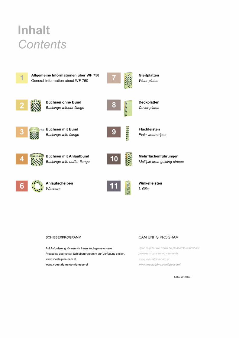
Allgemeine Informationen über WF 750 GleitplattenGeneral Information about WF 750 Wear plates
Büchsen ohne Bund DeckplattenBushings without flange Cover plates
Büchsen mit Bund FlachleistenBushings with flange Plain wearstripes
Büchsen mit Anlaufbund MehrflächenführungenBushings with buffer flange Multiple area guiding stripes
Anlaufscheiben WinkelleistenWashers L-Gibs
SCHIEBERPROGRAMM CAM UNITS PROGRAM
Auf Anforderung können wir Ihnen auch gerne unsere Upon request we would be pleased to submit our
Prospekte über unser Schieberprogramm zur Verfügung stellen. prospects concerning cam-units.
www.voestalpine-nem.at www.voestalpine-nem.at
www.voestalpine.com/giesserei www.voestalpine.com/giesserei
InhaltContents
Edition 2012 Rev.1
1
2
3
4
6
7
8
9
10
11
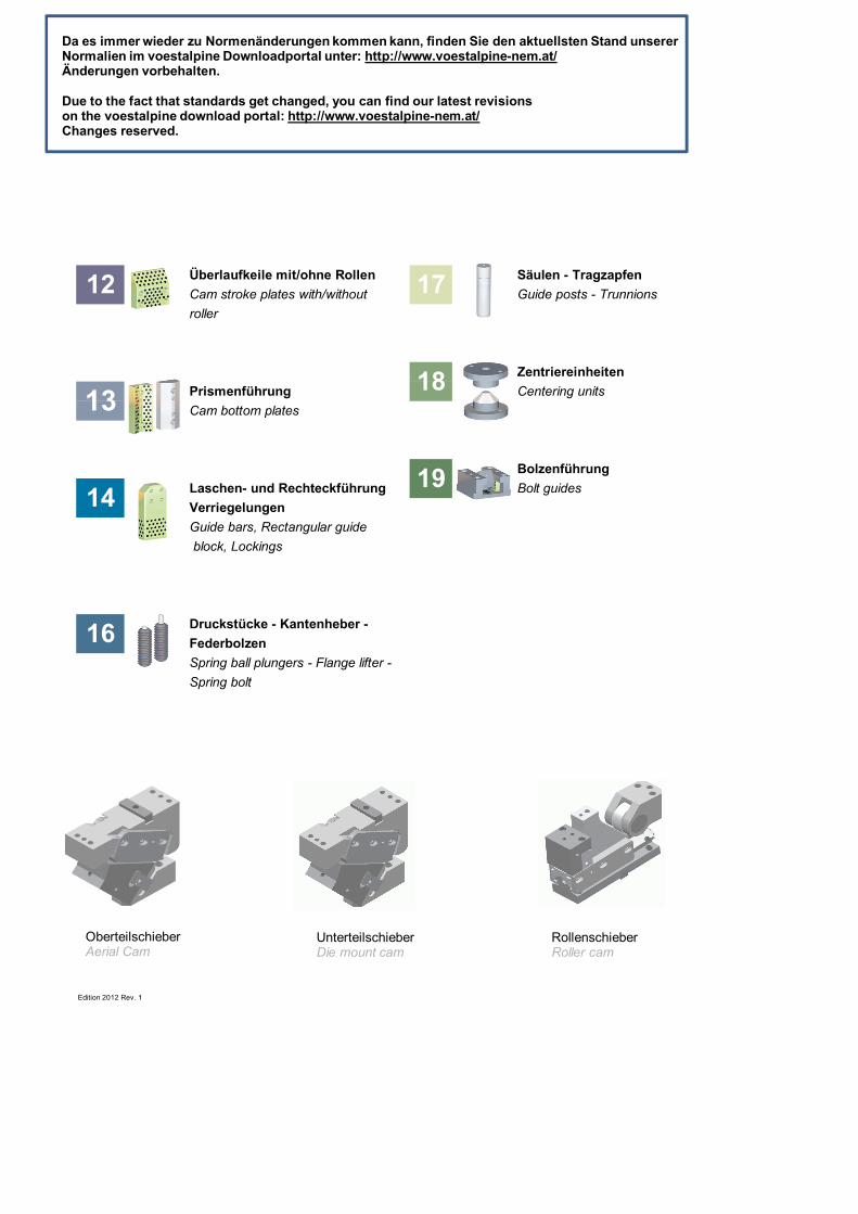
Überlaufkeile mit/ohne Rollen Säulen - TragzapfenCam stroke plates with/without Guide posts - Trunnionsroller
ZentriereinheitenPrismenführung Centering unitsCam bottom plates
BolzenführungLaschen- und Rechteckführung Bolt guidesVerriegelungenGuide bars, Rectangular guide block, Lockings
Druckstücke - Kantenheber -FederbolzenSpring ball plungers - Flange lifter -Spring bolt
Edition 2012 Rev. 1
16
12 17
1318
1419
OberteilschieberAerial Cam
UnterteilschieberDie mount cam
RollenschieberRoller cam
Da es immer wieder zu Normenänderungen kommen kann, finden Sie den aktuellsten Stand unsererNormalien im voestalpine Downloadportal unter: http://www.voestalpine-nem.at/Änderungen vorbehalten.
Due to the fact that standards get changed, you can find our latest revisionson the voestalpine download portal: http://www.voestalpine-nem.at/Changes reserved.

Maintenance free-self lubrication sliding
Instructions of application
Technical Informations
Service notes1.4
1.3
1.2
1.1
Wartungshinweise
1
elements WF 750
Wartungsfreie Gleitelemente WF 750
Anwendunghinweise
Allgemeine Informationen über voestalpineGleitelementeGeneral information about voestalpine slidingelements
Technische Informationen

Edition 2012 Rev.0
Die voestalpine Giesserei Linz GmbH erhebt den weltweiten Voestalpine Giesserei Linz GmbH is the worldwide leaderAnspruch auf Qualitäts- und Technologieführerschaft im in quality and technnology in the field of maintenanceBereich von wartungsfreien Gleitelementen. free sliding elements.
Die Forschungs- und Entwicklungsleistung stützt sich auf Our research and development services are based onnationale und internationale Zusammenarbeit mit national and international cooperation with researchForschungsinstituten, Universitäten, Kunden, Lieferanten institues, universities, customers, suppliers and foundries.und Gießereien. Ziel der Kooperation ist die optimale This cooperation aims to optimally utilise know-how andNutzung von Know-how und weltweit vorhandenen F&E wolrdwide R&D resources.Ressourcen.
Die voestalpine Giesserei Linz GmbH ist zertifiziert nach Voestalpine Giesserei Linz GmbH is certified toEN ISO 9001:2008 und ISO 14001:2004. EN ISO 9001:2008 and ISO 14001:2004.
11 Vorteile, die Ihnen Gleitelemente WF 750 Sliding elements WF 750 offer the followingbieten: advantages:
● wartungsfrei ● Maintenance free ● verschleißfest ● Wear resistant ● niedriger Reibungswiderstand ● Low frictional resistance ● Spitzentemperatur bis ca. 200 °C, kurzfristig ● Resistant against short term up to approx. 200 °C ● keine Verunreinigung durch austretendes Schmiermittel ● No impurity through discharge of lubrication ● umweltfreundlich ● Environmentally friendly ● korrosionsbeständig ● Corrosion resistant ● unempfindlich gegenüber Stoßbeanspruchung ● Insensitive to impact stress ● besonders geeignet bei oszillierender Gleitbewegung ● Specially suited for oscillating slide motions ● stick-slip-freies Gleiten ● Stick-slip-free sliding ● lange Lebensdauer ● Long life
Bevorzugter Einsatz von Gleitelementen Preferred applications for sliding elements -WF 750 in: WF 750:
● Automobilindustrie (Werkzeugführungen, ● Automotive industry (tool support, dies) Karosseriepressen) ● Kunststoffspritzgießmaschinen und ● Injection molding - machines and tools Spritzgießwerkzeuge ● Allgemeiner Maschinenbau ● Mechanical machine construction ● Stahl- und Walzwerke ● Steel and/or rolling mills ● Bau- und Steinindustrie ● Machine building - and stone industry ● Wehranlagen und Wasserbau ● Weir plants/ship building ● Schiffbau ● Heavy duty machine inustry ● Verpackungsinustrie ● Packaging industry ● Hebe- und Fördertechnik ● Lift and/or conveying engineering
Edition 2012 Rev. 0
Wartungsfreie Gleitelemente WF 750Maintenance free-self-lubrication sliding elements WF 750 1.1
EINBAUHINWEISE INSTALLATION GUIDELINESDie Aufnahmebohrung für die wartungsfreien Büchsen sollte The receiving hole for the maintenance free bushings shouldder ISO-Toleranz H7 entsprechen. Eine Überdeckung der confirm with ISO-tolerance H7. The overlapping of the fit isder Passung wird durch das Wählen des Toleranzfeldes der achieved through the tolerance zone of bushings, using asBüchse erreicht, zum Beispiel m6 für einen leichten Press- an example m6 for a light press fit. Please take intositz. Dabei ist zu berücksichtigen, dass sich der Innen- consideration that the inner diameter of the bushing afterdurchmesser des Gleitlagers nach dem Einpressen oder the press fit or shrink will get smaller. The bushing needsEinschrumpfen verkleinert. Nach dem Zusammenfügen to be secured against rotating after the installation. Thesollte die Büchse gegen Verdrehen gesichert werden. Das necessary running clearance of the pin or axle has to beerforderliche Laufspiel der Welle wird durch das Festlegen determined through the tolerance zone.des Toleranzfeldes bestimmt.
z.B. leichter Presssitz: Example for light press fit: Aufnahmebohrung H7 Receiving hole H7 Büchse KATALOG 2.1 m6/F7 Bushing catalog 2.1 m6/F7 Welle KATALOG 17.4 h6 für enges Lagerspiel Pin catalog 17.4 h6 for thight bearing play Welle KATALOG 17.8 f7 für größeres Lagerspiel Pin catalog 17.8 f7 for less tight bearing play
z.B. strenger Presssitz: Example for tight press fit: Aufnahmebohrung H7 Receiving hole H7 Büchse KATALOG 3.14 r6/E7 Bushing catalog 3.14 r6/E7 Welle KATALOG 17.4 h6 für enges Lagerspiel Pin cataolg 17.4 h6 for thight bearing play Welle KATALOG 17.8 f7 für größeres Lagerspiel Pin cataolg 17.8 f7 for less tight bearing play
Die Gleitflächen sind nach dem Einbau bzw. nach jeder After bushing installation or after cleaning, the slidingReinigung mit Öl zu versehen. Wir empfehlen, handels- surface should be treated with commercial availableübliche lithiumverseifte Öle zu verwenden. Lithium oil.
GENGENWERKSTOFF MATING MATERIALDie Härte des Gegenwerkstoffes soll im Vergleich zum The hardness of the ground mating material should beGrundwerkstoff WF 750 um mind. 100 HB höher sein. minimum 100 HB (approx. 15 HRC) higher than theOptimale Bedingungen werden mit gehärteten und ge- self-lubricating sliding elements.schliffenen Gegenwerkstoffen erreicht. Empfohlene Ober-flächengüte Rz 6,3 (Ra max. 0,8 µm).
TEMPERATUR TEMPERATUREKurzzeitige Temperaturspitzen bis ca. 200 °C sind For a short period of time, temperatures of up to approx.zulässig. 200 °C are permitted (approx. 392 °F)
SCHMIERSTOFF LUBRICANTUm eine optimale Schmierung zu erreichen, wird der To obtain the best possible lubrication the solid lubricantSchmierstoff in der Gleitrichtung überdeckend angeordnet. should be arranged in an overlapping pattern in slideDer Schmierstoffanteil an der Gleitfläche liegt zwischen direction. The amount of solid lubricant in proportion to the25% und 35%. Als Schmierstoff dient Grafit mit Zusätzen. sliding area is between 25 to 35 % of the total slidng area.Bei extremer Beanspruchung (z.B. Gleitgeschwindigkeit Graphite with additive is used as a solid lubricant.>0,5 m/s) ist eine Zusatzschmierung empfehlenswert. For extreme application, sliding speed > 0,5 m/s, additional
lubrication is recommmended.
Edition 2012 Rev.0
AnwendungshinweiseInstructions of application1.2
SONDERANFERTIGUNG SPECIAL DESIGN
BESTELLUNGEN PURCHASING
Angaben über Schrauben und Passstifte dienen nur zurDetails about screws and dowel pins are only for information.
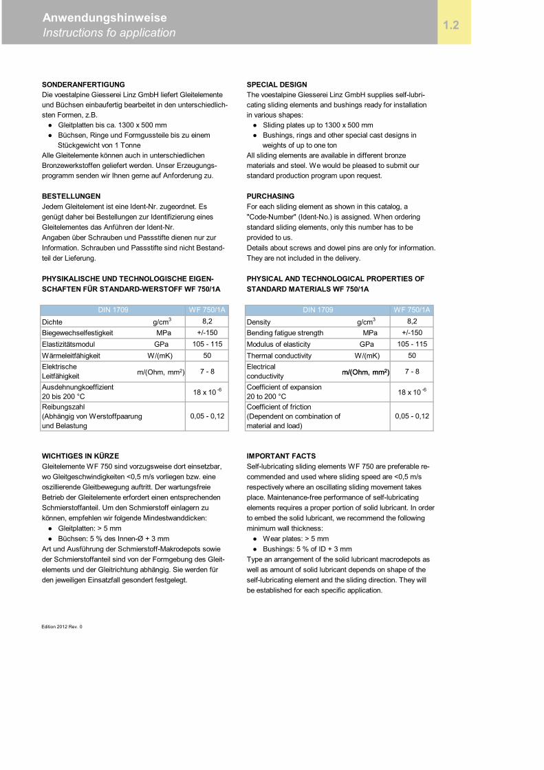
DIN 1709 WF 750/1A DIN 1709 WF 750/1A
Dichte g/cm3 8,2 Density g/cm3 8,2Biegewechselfestigkeit MPa +/-150 Bending fatigue strength MPa +/-150Elastizitätsmodul GPa 105 - 115 Modulus of elasticity GPa 105 - 115Wärmeleitfähigkeit W/(mK) 50 Thermal conductivity W/(mK) 50
WICHTIGES IN KÜRZE IMPORTANT FACTS
Edition 2012 Rev. 0
elements requires a proper portion of solid lubricant. In order
● Wear plates: > 5 mm ● Bushings: 5 % of ID + 3 mmType an arrangement of the solid lubricant macrodepots aswell as amount of solid lubricant depends on shape of theself-lubricating element and the sliding direction. They willbe established for each specific application.
den jeweiligen Einsatzfall gesondert festgelegt.
Self-lubricating sliding elements WF 750 are preferable re-commended and used where sliding speed are <0,5 m/srespectively where an oscillating sliding movement takesplace. Maintenance-free performance of self-lubricating
to embed the solid lubricant, we recommend the followingminimum wall thickness:
können, empfehlen wir folgende Mindestwanddicken: ● Gleitplatten: > 5 mm ● Büchsen: 5 % des Innen-Ø + 3 mmArt und Ausführung der Schmierstoff-Makrodepots sowieder Schmierstoffanteil sind von der Formgebung des Gleit-elements und der Gleitrichtung abhängig. Sie werden für
Gleitelemente WF 750 sind vorzugsweise dort einsetzbar,wo Gleitgeschwindigkeiten <0,5 m/s vorliegen bzw. eineoszillierende Gleitbewegung auftritt. Der wartungsfreieBetrieb der Gleitelemente erfordert einen entsprechendenSchmierstoffanteil. Um den Schmierstoff einlagern zu
Coefficient of expansion20 to 200 °C 18 x 10 -6
Coefficient of friction(Dependent on combination ofmaterial and load)
0,05 - 0,12
Electricalconductivity
teil der Lieferung.
STANDARD MATERIALS WF 750/1APHYSIKALISCHE UND TECHNOLOGISCHE EIGEN-SCHAFTEN FÜR STANDARD-WERSTOFF WF 750/1A
7 - 8
Jedem Gleitelement ist eine Ident-Nr. zugeordnet. Esgenügt daher bei Bestellungen zur Identifizierung eines
The voestalpine Giesserei Linz GmbH supplies self-lubri-cating sliding elements and bushings ready for installationin various shapes: ● Sliding plates up to 1300 x 500 mm ● Bushings, rings and other special cast designs in
All sliding elements are available in different bronzematerials and steel. We would be pleased to submit ourstandard production program upon request.
For each sliding element as shown in this catalog, a"Code-Number" (Ident-No.) is assigned. When ordering
Gleitelementes das Anführen der Ident-Nr. standard sliding elements, only this number has to beprovided to us.
They are not included in the delivery.
PHYSICAL AND TECHNOLOGICAL PROPERTIES OF
ElektrischeLeitfähigkeitAusdehnungkoeffizient20 bis 200 °CReibungszahl(Abhängig von Werstoffpaarungund Belastung
7 - 8
18 x 10 -6
0,05 - 0,12
Information. Schrauben und Passstifte sind nicht Bestand-
AnwendungshinweiseInstructions fo application
Die voestalpine Giesserei Linz GmbH liefert Gleitelementeund Büchsen einbaufertig bearbeitet in den unterschiedlich-sten Formen, z.B. ● Gleitplatten bis ca. 1300 x 500 mm
1.2
● Büchsen, Ringe und Formgussteile bis zu einem Stückgewicht von 1 TonneAlle Gleitelemente können auch in unterschiedlichenBronzewerkstoffen geliefert werden. Unser Erzeugungs-
weights of up to one ton
programm senden wir Ihnen gerne auf Anforderung zu.
m/(Ohm, mm2) m/(Ohm, mm2)m/(Ohm, mm2)
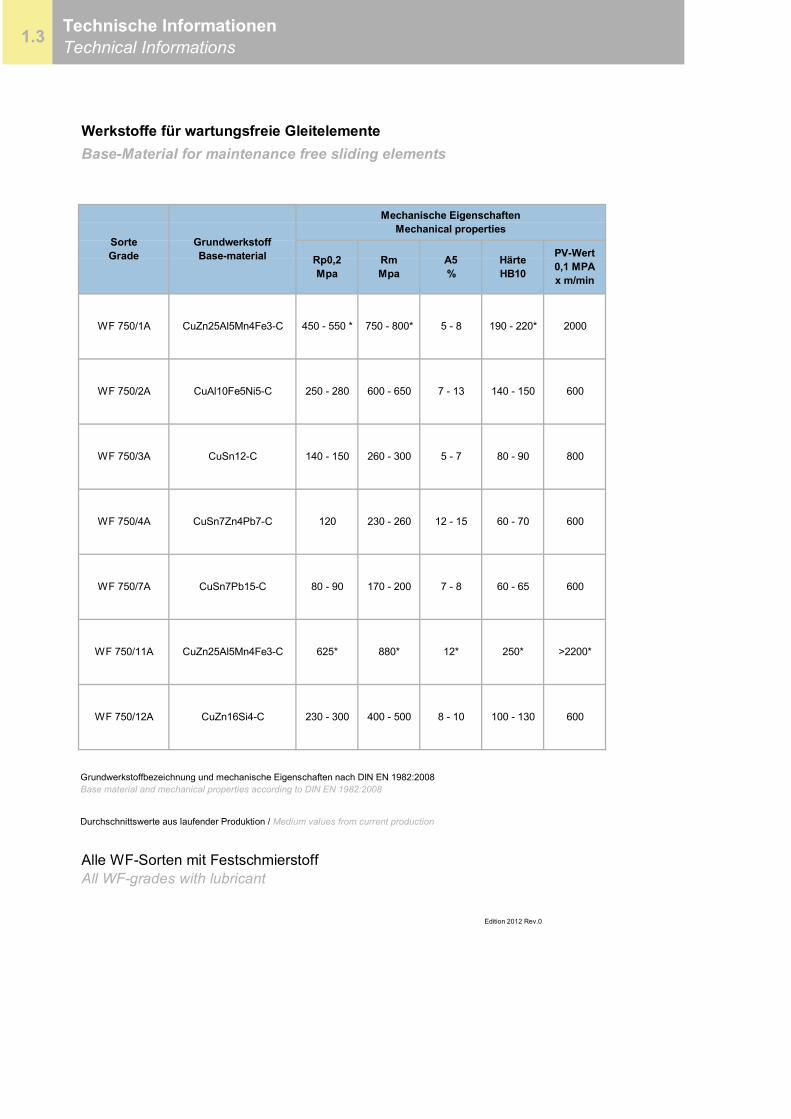
Werkstoffe für wartungsfreie GleitelementeBase-Material for maintenance free sliding elements
Durchschnittswerte aus laufender Produktion / Medium values from current production
Alle WF-Sorten mit FestschmierstoffAll WF-grades with lubricant
Rp0,2Mpa
GrundwerkstoffBase-material
SorteGrade
Grundwerkstoffbezeichnung und mechanische Eigenschaften nach DIN EN 1982:2008Base material and mechanical properties according to DIN EN 1982:2008
WF 750/2A
WF 750/3A 5 - 7 80 - 90 800
60 - 70 600
WF 750/7A CuSn7Pb15-C 80 - 90
Edition 2012 Rev.0
CuZn25Al5Mn4Fe3-C 450 - 550 * 750 - 800* 5 - 8 190 - 220* 2000
CuAl10Fe5Ni5-C 250 - 280 600 - 650 7 - 13 140 - 150 600
CuSn12-C 140 - 150 260 - 300
Mechanische EigenschaftenMechanical properties
1.3 Technische InformationenTechnical Informations
PV-Wert0,1 MPAx m/min
HärteHB10
A5%
RmMpa
WF 750/1A
170 - 200 7 - 8 60 - 65 600
WF 750/4A CuSn7Zn4Pb7-C 120 230 - 260 12 - 15
250* >2200*
WF 750/12A CuZn16Si4-C 230 - 300 400 - 500 8 - 10 100 - 130 600
WF 750/11A CuZn25Al5Mn4Fe3-C 625* 880* 12*
Edition 2012 Rev. 0
Technische InformationenTechnical informations 1.3
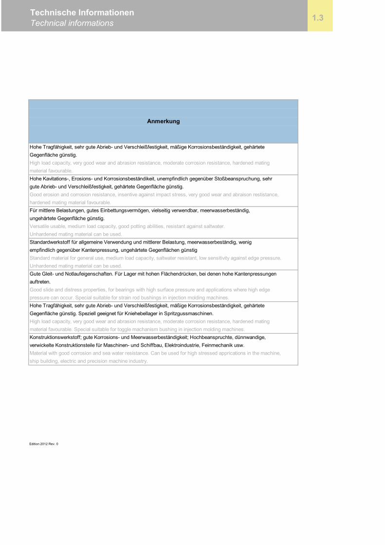
Anmerkung
gute Abrieb- und Verschleißfestigkeit, gehärtete Gegenfläche günstig.
auftreten.
Good erosion and corrosion resistance, insentive against impact stress, very good wear and abraison restistance,hardened mating material favourable.Für mittlere Belastungen, gutes Einbettungsvermögen, vielseitig verwendbar, meerwasserbeständig,ungehärtete Gegenfläche günstig.Versatile usable, medium load capacity, good potting abilities, resistant against saltwater.Unhardened mating material can be used.
Konstruktionswerkstoff; gute Korrosions- und Meerwasserbeständigkeit; Hochbeanspruchte, dünnwandige,verwickelte Konstruktionsteile für Maschinen- und Schiffbau, Elektroindustrie, Feinmechanik usw.Material with good corrosion and sea water resistance. Can be used for high stressed apprications in the machine,ship building, electric and precision machine industry.
Hohe Tragfähigkeit, sehr gute Abrieb- und Verschleißfestigkeit, mäßige Korrosionsbeständigkeit, gehärteteGegenfläche günstig.High load capacity, very good wear and abrasion resistance, moderate corrosion resistance, hardened matingmaterial favourable.Hohe Kavitations-, Erosions- und Korrosionsbeständikeit, unempfindlich gegenüber Stoßbeanspruchung, sehr
material favourable. Special suitable for toggle machanism bushing in injection molding machines.
Standardwerkstoff für allgemeine Verwendung und mittlerer Belastung, meerwasserbeständig, wenigempfindlich gegenüber Kantenpressung, ungehärtete Gegenflächen günstigStandard material for general use, medium load capacity, saltwater resistant, low sensitivity against edge pressure.Unhardened mating material can be used.Gute Gleit- und Notlaufeigenschaften. Für Lager mit hohen Flächendrücken, bei denen hohe Kantenpressungen
Good slide and distress properties, for bearings with high surface pressure and applications where high edgepressure can occur. Special suitable for strain rod bushings in injection molding machines.Hohe Tragfähigkeit, sehr gute Abrieb- und Verschleißfestigkeit, mäßige Korrosionsbeständigkeit, gehärteteGegenfläche günstig. Speziell geeignet für Kniehebellager in Spritzgussmaschinen.High load capacity, very good wear and abrasion resistance, moderate corrosion resistance, hardened mating
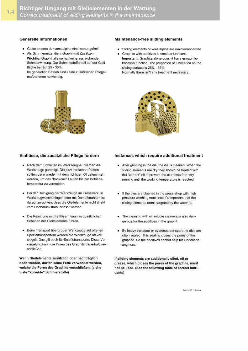
Generelle Informationen Maintenance-free sliding elements
● Gleitelemente der voestalpine sind wartungsfrei! ● Sliding elements of voestalpine are maintenance-free● Als Schmiermittel dient Graphit mit Zusätzen. ● Graphite with additives is used as lubricant.
Wichtig: Graphit alleine hat keine ausreichende Important: Graphite alone doesn't have enough lu- Schmierwirkung. Der Schmierstoffanteil auf der Gleit- brication function. The proportion of lubrication on the fläche beträgt 25 - 35%. sliding surface is 25% - 35%. Im generellen Betrieb sind keine zusätzlichen Pflege- Normally there isn't any treatment necessary. maßnahmen notwendig.
Einflüsse, die zusätzliche Pflege fordern Instances which require additional treatment
● Nach dem Schleifen im Werkzeugbau werden die ● After grinding in the die, the die is cleaned. When the Werkzeuge gereinigt. Die jetzt trockenen Platten sliding elements are dry they should be treated with sollten dann wieder mit dem richtigen Öl befeuchtet the "correct" oil to prevent the elements from dry werden, um das "trockene" Laufen bis zur Betriebs- running until the working temperature is reached temperatur zu vermeiden.
● Bei der Reinigung der Werkzeuge im Presswerk, in ● If the dies are cleaned in the press-shop with high Werkzeugwaschanlagen oder mit Dampfstrahlern ist pressure washing machines it's important that the darauf zu achten, dass die Gleitelemente nicht direkt sliding elements aren't targeted by the water-jet. vom Hochdruckstrahl erfasst werden.
● Die Reinigung mit Fettlösern kann zu zusätzlichem ● The cleaning with oil soluble cleaners is also dan- Schaden der Gleitelemente führen. gerous for the additives in the graphit.
● Beim Transport übergroßer Werkzeuge auf offenen ● By heavy transport or overseas transport the dies are Spezialtransportern werden die Werkzeuge oft ver- often sealed. This sealing closes the pores of the siegelt. Das gilt auch für Schiffstransporte. Diese Ver- graphite. So the additives cannot help for lubrication siegelung kann die Poren des Graphits dauerhaft ver- anymore. schließen.
Wenn Gleitelemente zusätzlich oder nachträglich If sliding elements are additionally oiled, oil orbeölt werden, dürfen keine Fette verwendet werden, grease, which closes the pores of the graphite, mustwelche die Poren des Graphits verschließen. (siehe not be used. (See the following table of correct lubri-Liste "korrekte" Schmierstoffe) cants)
Edition 2012 Rev.0
1.4 Richtiger Umgang mit Gleitelementen in der WartungCorrect treatment of sliding elements in the maintenance
Auflistung korrekter Schmierstoffe List of correct lubricants
Firma Öle Fette Comp. Oil Grease
BP Autran DX II Energrease BP Autran DX II Energrease
OMV ATF Serie OMV signum CX 2 OMV ATF Serie OMV signum CX 2
Agip Potra ATF Agip GR MU 2 Agip Potra ATF Agip GR MU 2
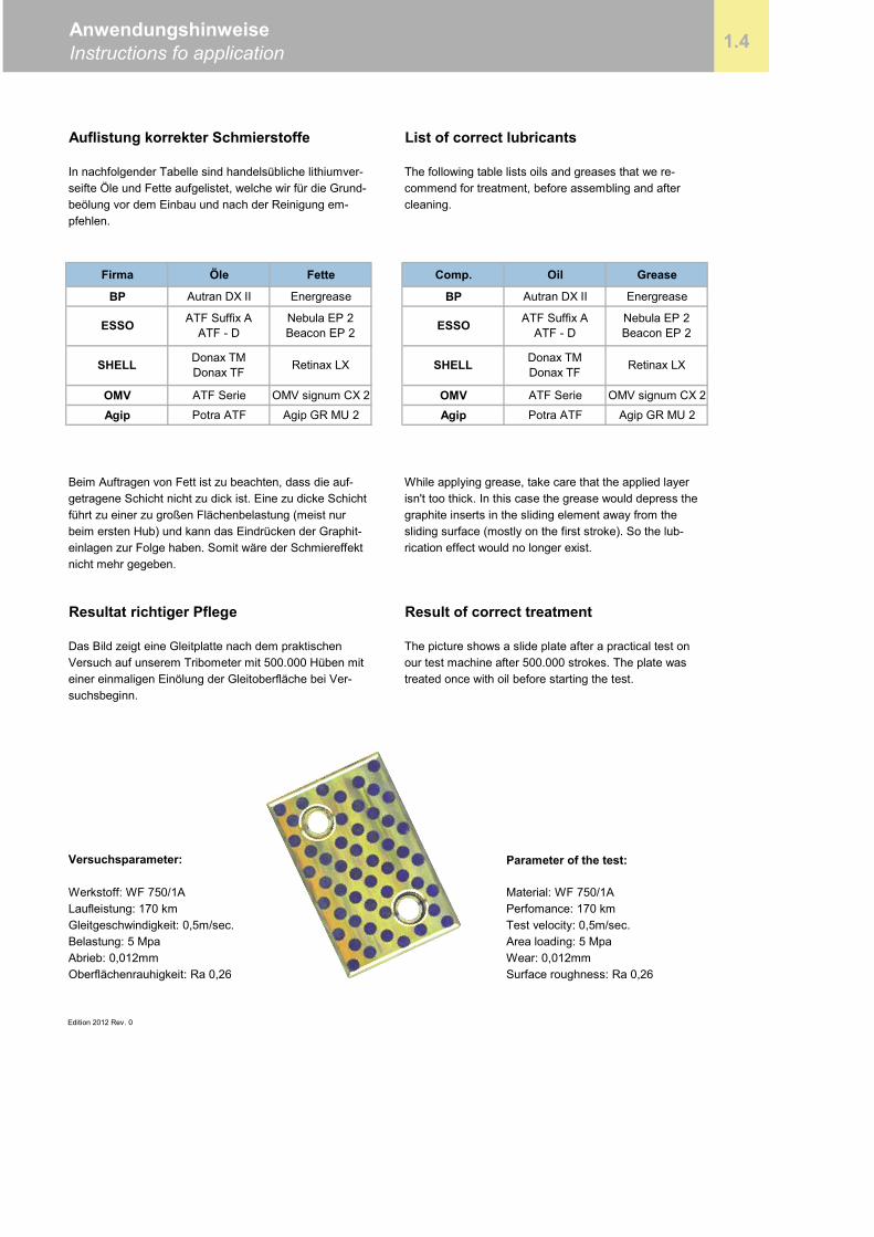
Resultat richtiger Pflege Result of correct treatment
Parameter of the test:
Edition 2012 Rev. 0
AnwendungshinweiseInstructions fo application 1.4
Donax TMDonax TFSHELL Retinax LX
ESSO ATF Suffix AATF - D
Nebula EP 2Beacon EP 2 ESSO
cleaning.
Nebula EP 2Beacon EP 2
SHELL Donax TMDonax TF Retinax LX
pfehlen.
Beim Auftragen von Fett ist zu beachten, dass die auf-
graphite inserts in the sliding element away from thesliding surface (mostly on the first stroke). So the lub-rication effect would no longer exist.
getragene Schicht nicht zu dick ist. Eine zu dicke Schichtführt zu einer zu großen Flächenbelastung (meist nur
einlagen zur Folge haben. Somit wäre der Schmiereffekt
Das Bild zeigt eine Gleitplatte nach dem praktischenVersuch auf unserem Tribometer mit 500.000 Hüben mit
While applying grease, take care that the applied layer
The picture shows a slide plate after a practical test onour test machine after 500.000 strokes. The plate was
The following table lists oils and greases that we re-commend for treatment, before assembling and after
Laufleistung: 170 kmGleitgeschwindigkeit: 0,5m/sec.
Versuchsparameter:
Werkstoff: WF 750/1A
nicht mehr gegeben.
ATF Suffix AATF - D
isn't too thick. In this case the grease would depress the
suchsbeginn.
In nachfolgender Tabelle sind handelsübliche lithiumver-seifte Öle und Fette aufgelistet, welche wir für die Grund-beölung vor dem Einbau und nach der Reinigung em-
treated once with oil before starting the test.
beim ersten Hub) und kann das Eindrücken der Graphit-
einer einmaligen Einölung der Gleitoberfläche bei Ver-
Belastung: 5 Mpa
Surface roughness: Ra 0,26Abrieb: 0,012mmOberflächenrauhigkeit: Ra 0,26
Material: WF 750/1APerfomance: 170 kmTest velocity: 0,5m/sec.Area loading: 5 MpaWear: 0,012mm

Büchsen ohne BundBushings without flangeWF 750
2
Büchsen ohne BundBushings without flange2.1
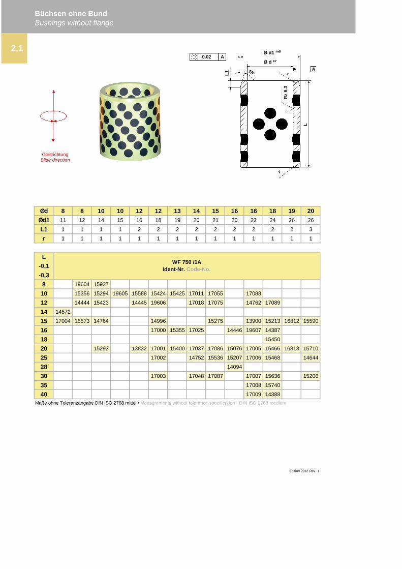
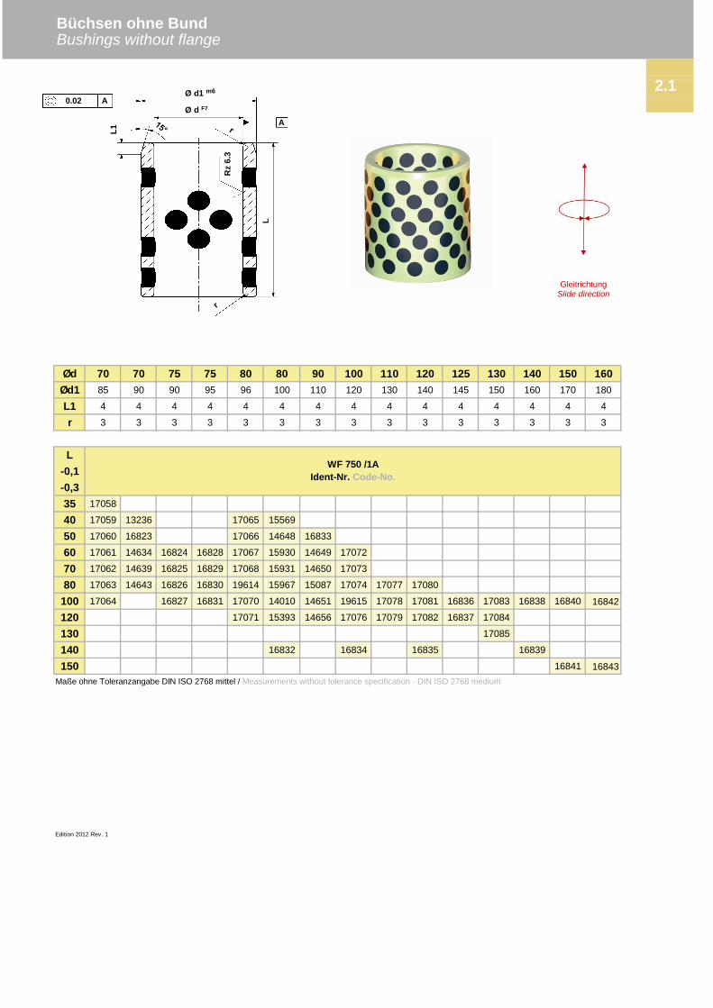
Büchsen ohne Bund Bushings without flange
Ød 8 8 10 10 12 12 13 14 15 16 16 18 19 20Ød1 11 12 14 15 16 18 19 20 21 20 22 24 26 26
L1 1 1 1 1 2 2 2 2 2 2 2 2 2 3
r 1 1 1 1 1 1 1 1 1 1 1 1 1 1
L-0,1-0,3
8 19604 15937
10 15356 15294 19605 15588 15424 15425 17011 17055 17088
12 14444 15423 14445 19606 17018 17075 14762 17089
14 14572
15 17004 15573 14764 14996 15275 13900 15213 16812 15590
16 17000 15355 17025 14446 19607 14387
18 15450
20 15293 13832 17001 15400 17037 17086 15076 17005 15466 16813 15710
25 17002 14752 15536 15207 17006 15468 14644
28 14094
30 17003 17048 17087 17007 15636 15206
35 17008 15740
40 17009 14388Maße ohne Toleranzangabe DIN ISO 2768 mittel / Measurements without tolerance specification - DIN ISO 2768 medium
WF 750 /1AIdent-Nr. Code-No.
2.1
Edition 2012 Rev. 1
GleitrichtungSlide direction
Ø d1 m6
Ø d F7
L1
L
Rz
6.3
0.02 A
A
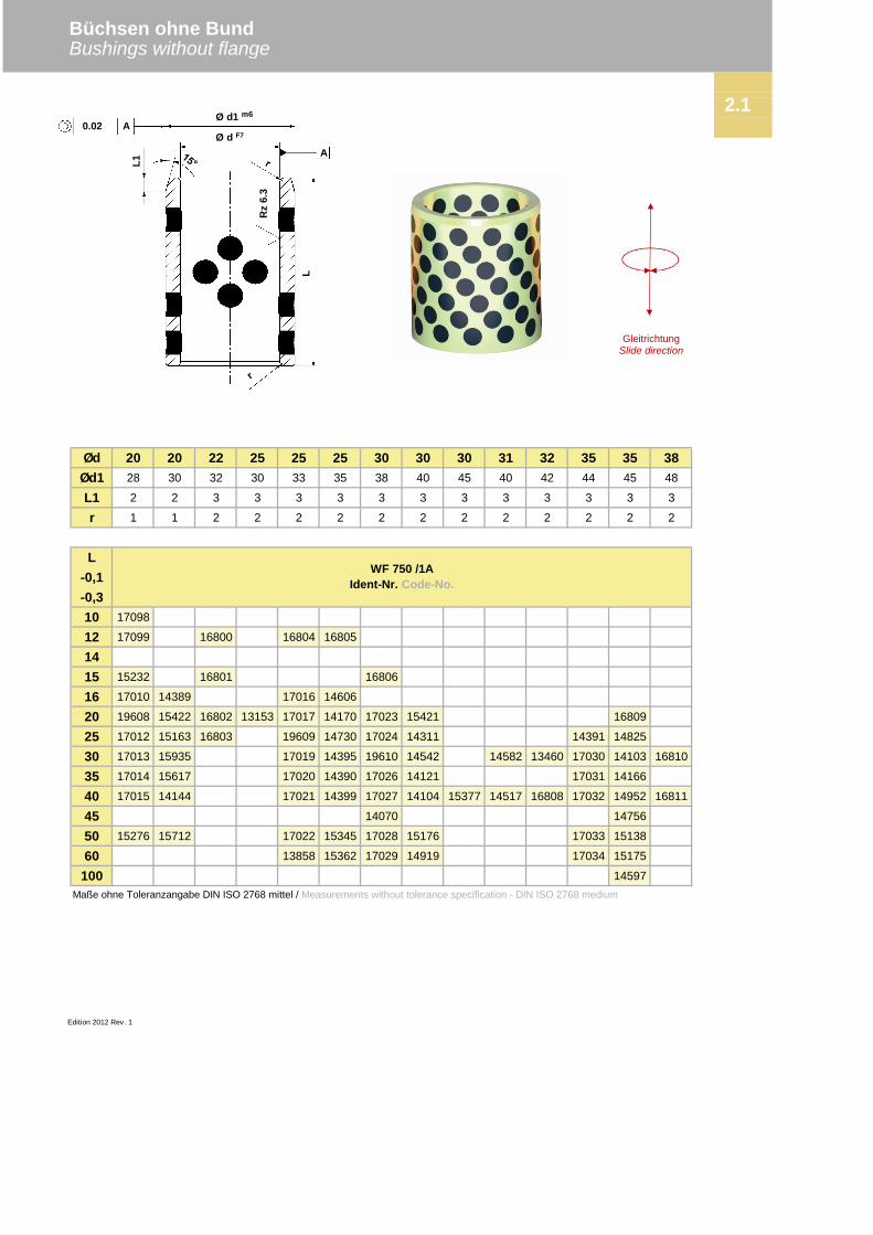
Büchsen ohne BundBushings without flange
Ød 20 20 22 25 25 25 30 30 30 31 32 35 35 38Ød1 28 30 32 30 33 35 38 40 45 40 42 44 45 48
L1 2 2 3 3 3 3 3 3 3 3 3 3 3 3
r 1 1 2 2 2 2 2 2 2 2 2 2 2 2
L-0,1-0,310 17098
12 17099 16800 16804 16805
1415 15232 16801 16806
16 17010 14389 17016 14606
20 19608 15422 16802 13153 17017 14170 17023 15421 16809
25 17012 15163 16803 19609 14730 17024 14311 14391 14825
30 17013 15935 17019 14395 19610 14542 14582 13460 17030 14103 16810
35 17014 15617 17020 14390 17026 14121 17031 14166
40 17015 14144 17021 14399 17027 14104 15377 14517 16808 17032 14952 16811
45 14070 14756
50 15276 15712 17022 15345 17028 15176 17033 15138
60 13858 15362 17029 14919 17034 15175
100 14597Maße ohne Toleranzangabe DIN ISO 2768 mittel / Measurements without tolerance specification - DIN ISO 2768 medium
2.1
WF 750 /1AIdent-Nr. Code-No.
Edition 2012 Rev. 1
GleitrichtungSlide direction
Ø d1 m6
Ø d F7L1
L
Rz
6.3
0.02 A
A
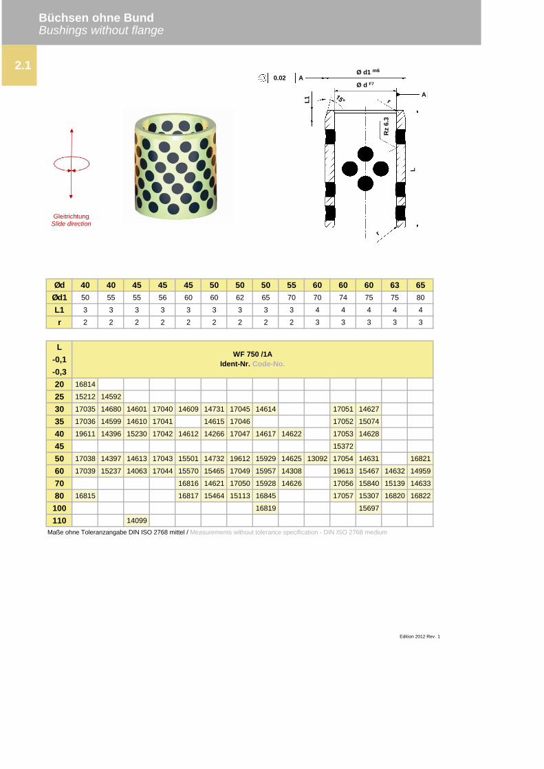
Büchsen ohne BundBushings without flange
Ød 40 40 45 45 45 50 50 50 55 60 60 60 63 65Ød1 50 55 55 56 60 60 62 65 70 70 74 75 75 80
L1 3 3 3 3 3 3 3 3 3 4 4 4 4 4
r 2 2 2 2 2 2 2 2 2 3 3 3 3 3
L-0,1-0,320 16814
25 15212 14592
30 17035 14680 14601 17040 14609 14731 17045 14614 17051 14627
35 17036 14599 14610 17041 14615 17046 17052 15074
40 19611 14396 15230 17042 14612 14266 17047 14617 14622 17053 14628
45 15372
50 17038 14397 14613 17043 15501 14732 19612 15929 14625 13092 17054 14631 16821
60 17039 15237 14063 17044 15570 15465 17049 15957 14308 19613 15467 14632 14959
70 16816 14621 17050 15928 14626 17056 15840 15139 14633
80 16815 16817 15464 15113 16845 17057 15307 16820 16822
100 16819 15697
110 14099Maße ohne Toleranzangabe DIN ISO 2768 mittel / Measurements without tolerance specification - DIN ISO 2768 medium
2.1
WF 750 /1AIdent-Nr. Code-No.
Edition 2012 Rev. 1
GleitrichtungSlide direction
Ø d1 m6
Ø d F7
L1
L
Rz
6.3
0.02 A
A
Büchsen ohne BundBushings without flange
Ød 70 70 75 75 80 80 90 100 110 120 125 130 140 150 160Ød1 85 90 90 95 96 100 110 120 130 140 145 150 160 170 180
L1 4 4 4 4 4 4 4 4 4 4 4 4 4 4 4
r 3 3 3 3 3 3 3 3 3 3 3 3 3 3 3
L-0,1-0,335 17058
40 17059 13236 17065 15569
50 17060 16823 17066 14648 16833
60 17061 14634 16824 16828 17067 15930 14649 17072
70 17062 14639 16825 16829 17068 15931 14650 17073
80 17063 14643 16826 16830 19614 15967 15087 17074 17077 17080
100 17064 16827 16831 17070 14010 14651 19615 17078 17081 16836 17083 16838 16840 16842
120 17071 15393 14656 17076 17079 17082 16837 17084
130 17085
140 16832 16834 16835 16839
150 16841 16843Maße ohne Toleranzangabe DIN ISO 2768 mittel / Measurements without tolerance specification - DIN ISO 2768 medium
2.1
Edition 2012 Rev. 1
WF 750 /1AIdent-Nr. Code-No.
GleitrichtungSlide direction
Ø d1 m6
Ø d F7L1
L
Rz
6.3
0.02 A
A

Büchsen und Klammern
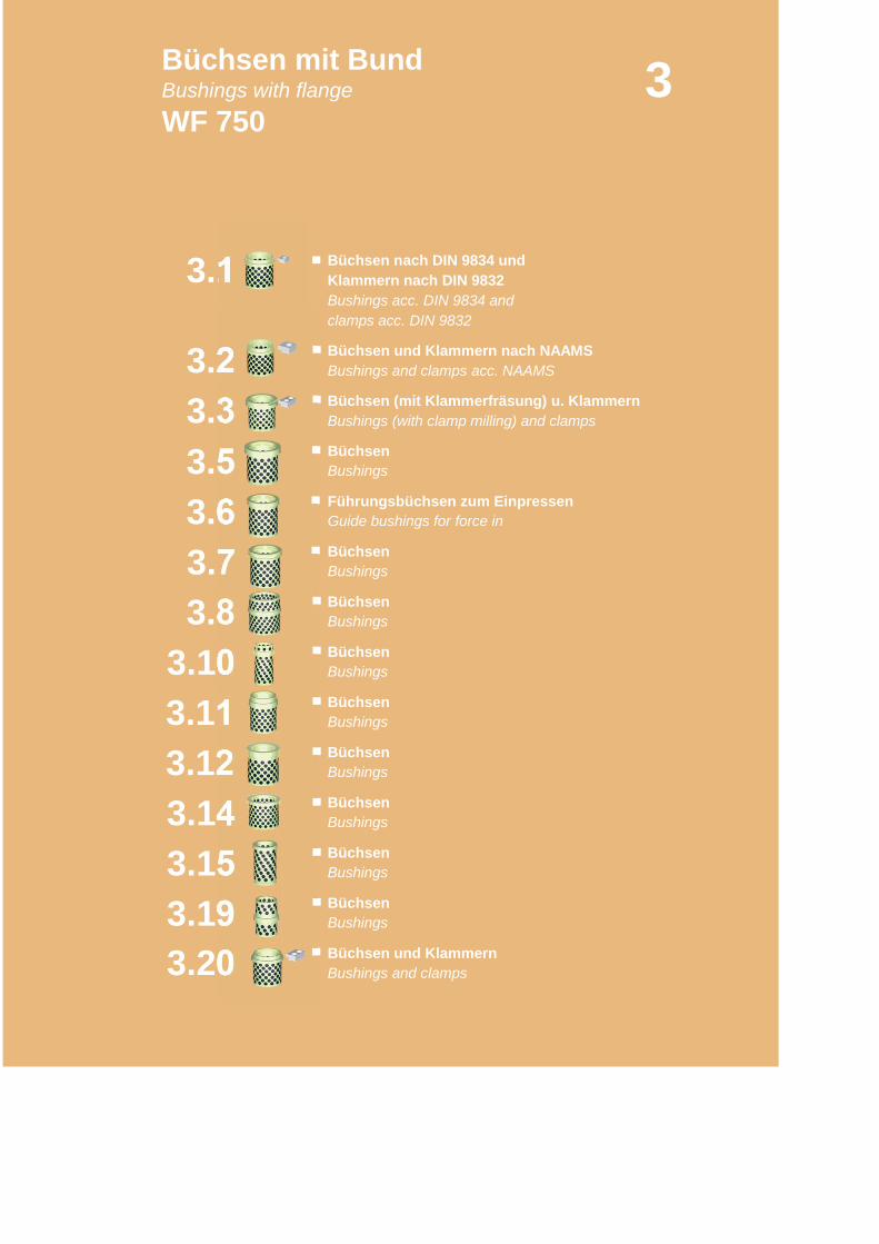
Büchsen mit BundBushings with flangeWF 750
3
3.6
3.1
Bushings and clamps acc. NAAMS
Büchsen nach DIN 9834 undKlammern nach DIN 9832Bushings acc. DIN 9834 andclamps acc. DIN 9832
Büchsen und Klammern nach NAAMS
Büchsen (mit Klammerfräsung) u. KlammernBushings (with clamp milling) and clamps
Büchsen
3.11
3.2
3.5
3.7
3.10
3.3
3.8
3.143.153.193.20
3.12
Bushings
Führungsbüchsen zum Einpressen
Büchsen
Guide bushings for force in
BüchsenBushings
BüchsenBushings
BüchsenBushings
BüchsenBushings
BüchsenBushings
Bushings and clamps
Bushings
BüchsenBushings
BüchsenBushings
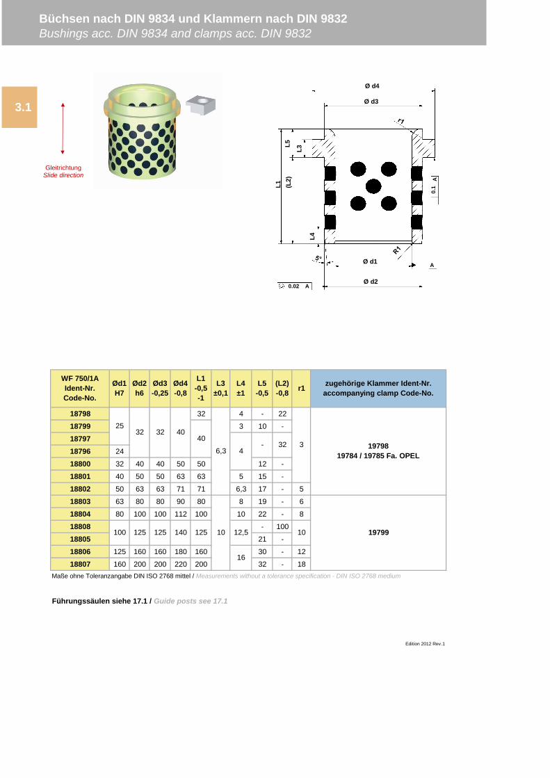
18798 32 4 - 22
18799 3 10 -
1879718796 24
18800 32 40 40 50 50 12 -
18801 40 50 50 63 63 5 15 -
18802 50 63 63 71 71 6,3 17 - 5
18803 63 80 80 90 80 8 19 - 6
18804 80 100 100 112 100 10 22 - 8
18808 - 100
18805 21 -
18806 125 160 160 180 160 30 - 12
18807 160 200 200 220 200 32 - 18Maße ohne Toleranzangabe DIN ISO 2768 mittel / Measurements without a tolerance specification - DIN ISO 2768 medium
Führungssäulen siehe 17.1 / Guide posts see 17.1
Edition 2012 Rev.1
10 12,5
16
10100 125 125 140 125
r1 zugehörige Klammer Ident-Nr.accompanying clamp Code-No.
1979819784 / 19785 Fa. OPEL
19799
2532 32 40
40
4- 32
6,33
L1-0,5-1
L3±0,1
L4±1
L5-0,5
(L2)-0,8
WF 750/1AIdent-Nr.Code-No.
Ød1H7
Ød2h6
Ød3-0,25
Ød4-0,8
3.1
Büchsen nach DIN 9834 und Klammern nach DIN 9832Bushings acc. DIN 9834 and clamps acc. DIN 9832
Ø d3
Ø d4
Ø d1
A0.02Ø d2
A
0.1
A
L1 (L2)
L4
L3
L5
GleitrichtungSlide direction
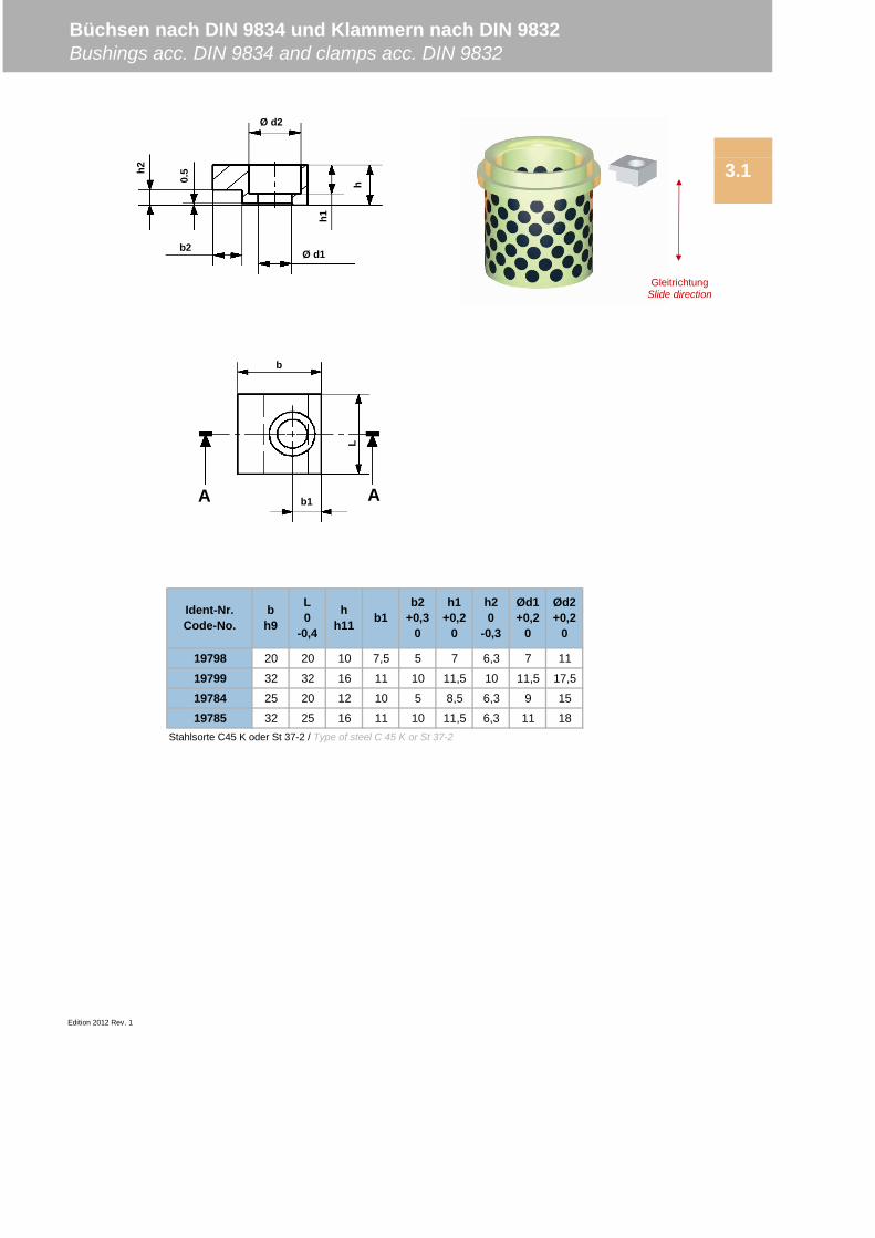
19798 20 20 10 7,5 5 7 6,3 7 11
19799 32 32 16 11 10 11,5 10 11,5 17,5
19784 25 20 12 10 5 8,5 6,3 9 15
19785 32 25 16 11 10 11,5 6,3 11 18Stahlsorte C45 K oder St 37-2 / Type of steel C 45 K or St 37-2
Edition 2012 Rev. 1
b2+0,3
0
h1+0,2
0
h20
-0,3
Ød1+0,2
0
Ød2+0,2
0
Ident-Nr.Code-No.
bh9
L0
-0,4
hh11 b1
3.1
Büchsen nach DIN 9834 und Klammern nach DIN 9832Bushings acc. DIN 9834 and clamps acc. DIN 9832
Ø d2
Ø d1b2
h2
0.5
h1
hb
b1
L
A A
GleitrichtungSlide direction

Edition 2012 Rev. 0
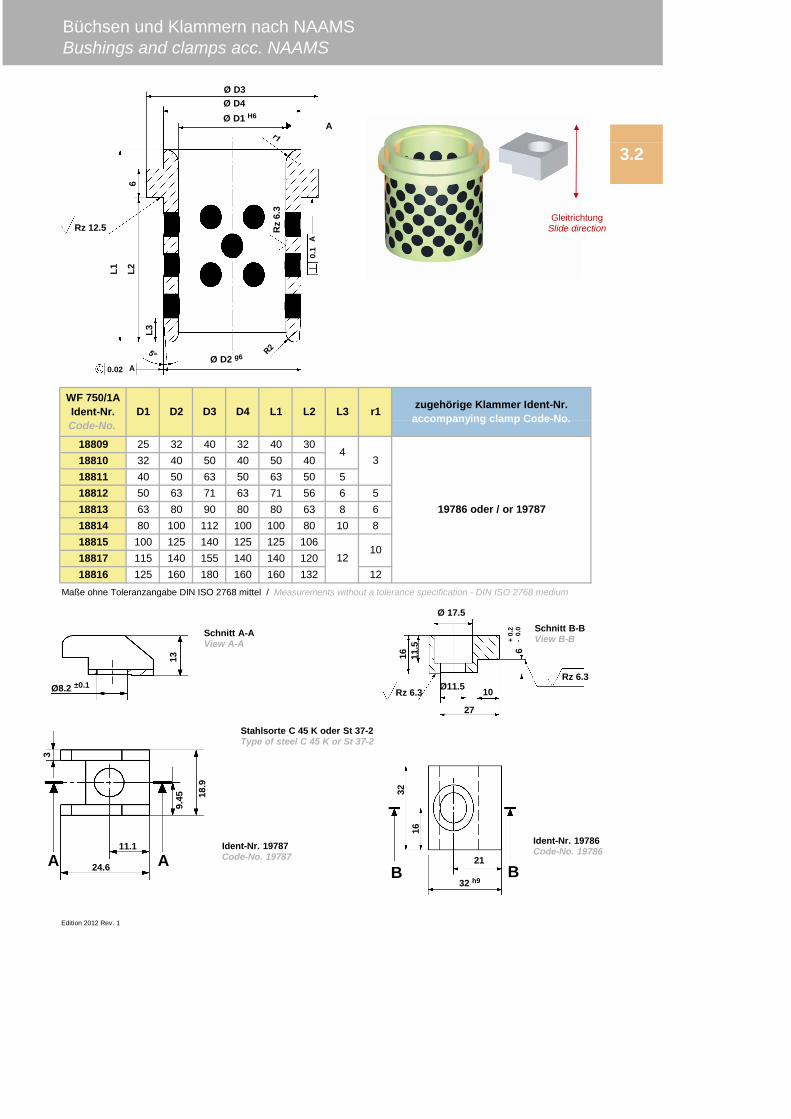
18809 25 32 40 32 40 3018810 32 40 50 40 50 4018811 40 50 63 50 63 50 518812 50 63 71 63 71 56 6 518813 63 80 90 80 80 63 8 618814 80 100 112 100 100 80 10 818815 100 125 140 125 125 10618817 115 140 155 140 140 12018816 125 160 180 160 160 132 12
Edition 2012 Rev. 1
Büchsen und Klammern nach NAAMSBushings and clamps acc. NAAMS
WF 750/1AIdent-Nr.Code-No.
3
3.2
D1 D2 D3 D4 L1 L2 r1
Maße ohne Toleranzangabe DIN ISO 2768 mittel / Measurements without a tolerance specification - DIN ISO 2768 medium
1012
L3
19786 oder / or 19787
zugehörige Klammer Ident-Nr.accompanying clamp Code-No.
4
13
Ø8.2 ±0.1
Stahlsorte C 45 K oder St 37-2Type of steel C 45 K or St 37-2
Ident-Nr. 19786Code-No. 19786
Ø D3Ø D4Ø D1 H6
A
A
Rz 12.5 Rz
6.3
0.1
0.02
L1 L2
L3
6
Ø D2 g6
A
6+
0.2
-0.
0
Ø 17.5
Ø11.5
27
10Rz 6.3Rz 6.3
16 11.5
Schnitt A-AView A-A
Schnitt B-BView B-B
11.1
24.6
9.45
3
18.9
AAIdent-Nr. 19787Code-No. 19787 21
32 h9
1632
B B
GleitrichtungSlide direction
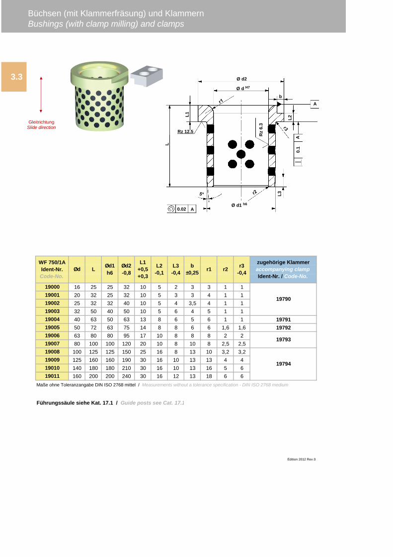
19000 16 25 25 32 10 5 2 3 3 1 119001 20 32 25 32 10 5 3 3 4 1 119002 25 32 32 40 10 5 4 3,5 4 1 119003 32 50 40 50 10 5 6 4 5 1 119004 40 63 50 63 13 8 6 5 6 1 1 1979119005 50 72 63 75 14 8 8 6 6 1,6 1,6 1979219006 63 80 80 95 17 10 8 8 8 2 219007 80 100 100 120 20 10 8 10 8 2,5 2,519008 100 125 125 150 25 16 8 13 10 3,2 3,219009 125 160 160 190 30 16 10 13 13 4 419010 140 180 180 210 30 16 10 13 16 5 619011 160 200 200 240 30 16 12 13 18 6 6
Edition 2012 Rev.0
Büchsen (mit Klammerfräsung) und KlammernBushings (with clamp milling) and clamps
b±0,25 r1 r2 r3
-0,4
zugehörige Klammeraccompanying clampIdent-Nr. / Code-No.
WF 750/1AIdent-Nr.Code-No.
L1+0,5+0,3
L2-0,1
L3-0,4
Maße ohne Toleranzangabe DIN ISO 2768 mittel / Measurements without a tolerance specification - DIN ISO 2768 medium
Führungssäule siehe Kat. 17.1 / Guide posts see Cat. 17.1
3.3
Ød L Ød1h6
Ød2-0,8
19790
19794
19793
Ø d2
Ø d H7
Rz 12.5
Ø d1 h6
L1
L3
L
b
L2
Rz
6.3
0.02 A
0.1
A
A
GleitrichtungSlide direction
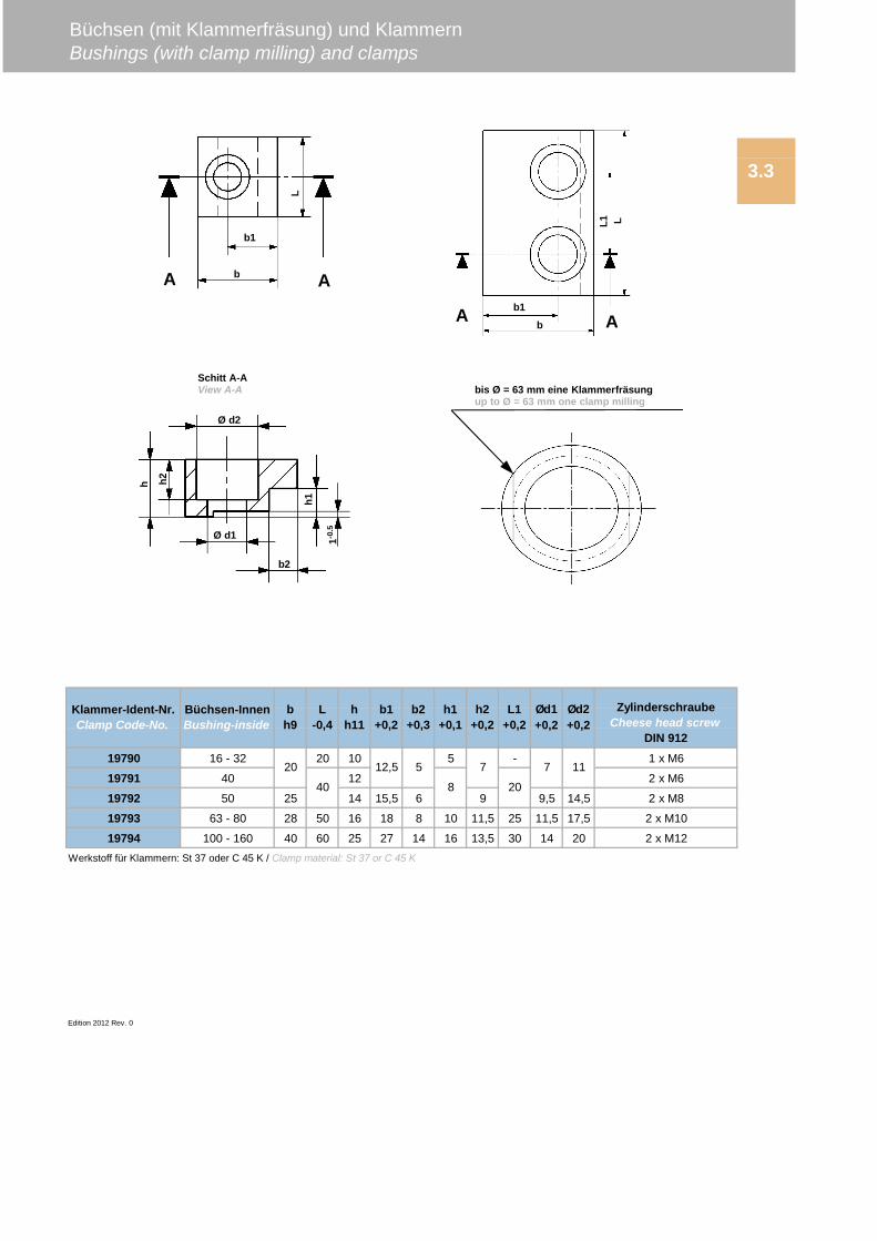
19790 16 - 32 20 10 5 - 1 x M6
19791 40 12 2 x M6
19792 50 25 14 15,5 6 9 9,5 14,5 2 x M8
19793 63 - 80 28 50 16 18 8 10 11,5 25 11,5 17,5 2 x M10
19794 100 - 160 40 60 25 27 14 16 13,5 30 14 20 2 x M12
Edition 2012 Rev. 0
bh9
h1+0,1
b2+0,3
b1+0,2
hh11
L-0,4
512,5
40
20
20
Büchsen-InnenBushing-inside
ZylinderschraubeCheese head screw
DIN 912
Ød2+0,2
Ød1+0,2
L1+0,2
h2+0,2
Werkstoff für Klammern: St 37 oder C 45 K / Clamp material: St 37 or C 45 K
Klammer-Ident-Nr.Clamp Code-No.
1177
8
Büchsen (mit Klammerfräsung) und KlammernBushings (with clamp milling) and clamps
3.3
Ø d2
Ø d1
b2
h2h
1-0.5
h1
bis Ø = 63 mm eine Klammerfräsungup to Ø = 63 mm one clamp milling
Schitt A-AView A-A
b
b1
LA A
b1
b
L1 L
A A
2628
32 55 40 504042505263 80 80 9080 100 100 110100 125 125 135
1930019301
75 63
Edition 2012 Rev. 1
19306
19308
1930319304
Maße ohne Toleranzangabe DIN ISO 2768 mittel / Measurementswithout a tolerance specification - DIN ISO 2768 medium
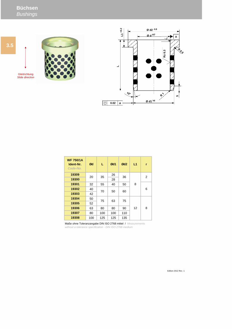
BüchsenBushings
3.5
Ød L Ød1 Ød2 L1 rWF 750/1AIdent-Nr.Code-No.
19309
19307
20
19305
2
6
12 8
70 50 60
35 36
8
75
19302
LL1
+0.2 Ø d2 -0.8
Ø d H7
Ø d1 h60.02 A
A
5
Rz
6.3
GleitrichtungSlide direction
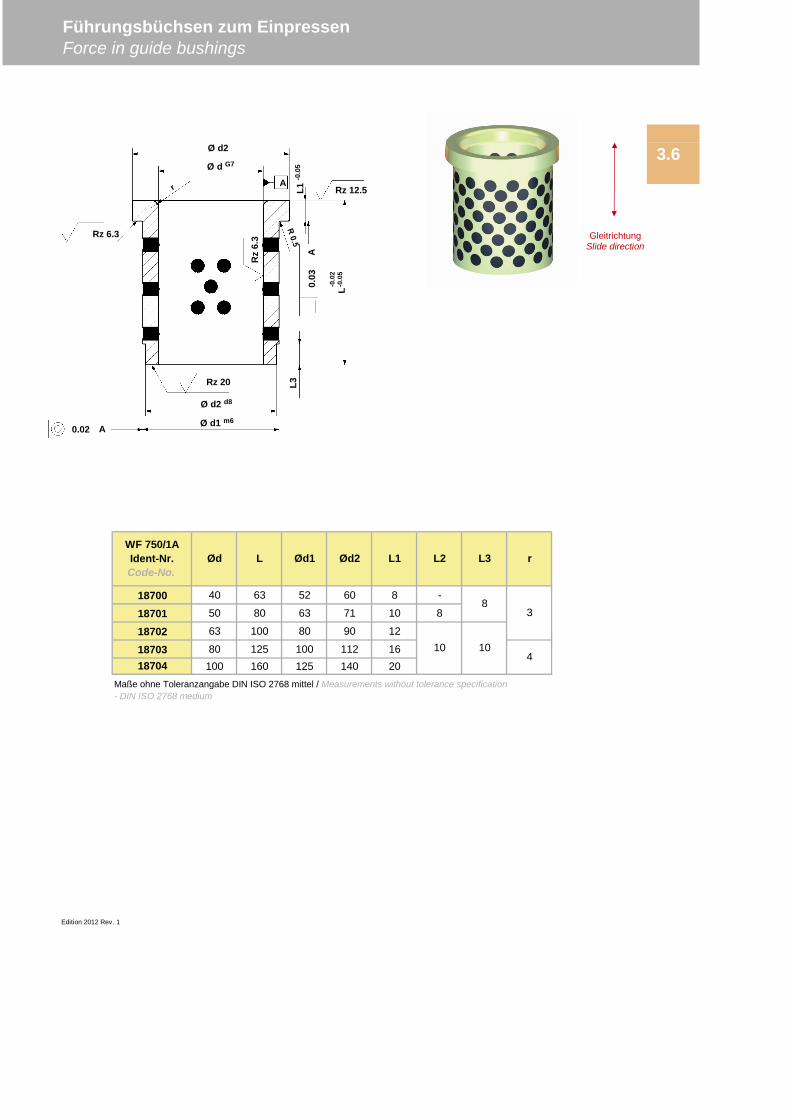
18700 40 63 52 60 8 -
18701 50 80 63 71 10 8
18702 63 100 80 90 12
18703 80 125 100 112 1618704 100 160 125 140 20
Maße ohne Toleranzangabe DIN ISO 2768 mittel / Measurements without tolerance specification- DIN ISO 2768 medium
Edition 2012 Rev. 1
L2 L3 r
10 10
83
4
WF 750/1AIdent-Nr.Code-No.
Ød L Ød1 Ød2 L1
Führungsbüchsen zum EinpressenForce in guide bushings
3.6
GleitrichtungSlide direction
Ø d2
Ø d G7
Ø d2 d8
Ø d1 m60.02 A
0.03
A
L3Rz 20
Rz 6.3
Rz
6.3
L1-0
.05
L-0
.02
-0.0
5
Rz 12.5A
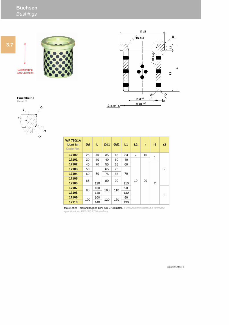
17100 25 40 35 45 33 7 1017101 30 50 40 50 4017102 40 70 55 65 6017103 50 65 7517104 60 75 851710517106 120 11017107 100 9017108 140 13017109 100 9017110 140 130
80
100
Maße ohne Toleranzangabe DIN ISO 2768 mittel / Measurements without a tolerancespecification - DIN ISO 2768 medium
r2
2
3
2
1
80
65
Edition 2012 Rev. 0
20
120
Ød2
80
70
90
110
130
100
10
BüchsenBushings
3.7
WF 750/1AIdent-Nr.Code-No.
Ød L Ød1 L1 L2 r r1
3
A
Ø d2
Rz 6.3
Rz
6.3
L1
L
L2
0.02 A
Ø d H7
Ø d1 m6
X
Einzelheit XDetail X
GleitrichtungSlide direction
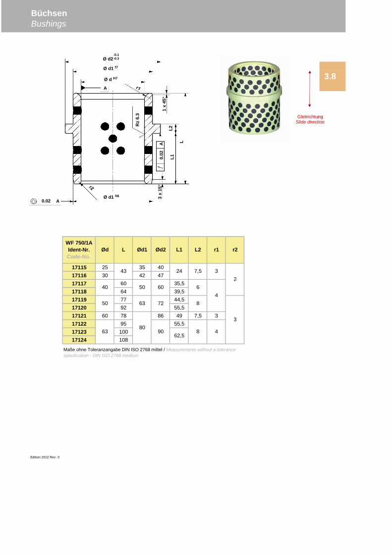
17115 25 35 4017116 30 42 4717117 60 35,517118 64 39,517119 77 44,517120 92 55,517121 60 78 86 49 7,5 317122 95 55,517123 10017124 108
Edition 2012 Rev. 0
62,58
8
6
Maße ohne Toleranzangabe DIN ISO 2768 mittel / Measurements without a tolerancespecification - DIN ISO 2768 medium
4
463
50
63
8090
72
60
50
3
2
WF 750/1AIdent-Nr.Code-No.
Ød L Ød1 Ød2 L1 L2 r1 r2
43
40
24 7,5 3
BüchsenBushings
3.8
Ø d2-0.1-0.3
Ø d1 f7
Ø d H7
A
A
A
0.02
0.02
Rz
6.3
Ø d1 h6 3x
15°
L1L2
L
1x
45°
GleitrichtungSlide direction
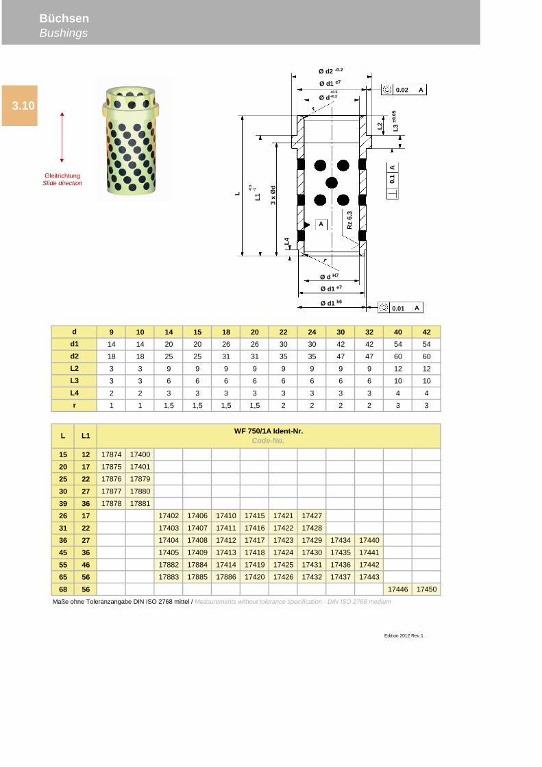
9 10 14 15 18 20 22 24 30 32 40 4214 14 20 20 26 26 30 30 42 42 54 54
18 18 25 25 31 31 35 35 47 47 60 60
3 3 9 9 9 9 9 9 9 9 12 12
3 3 6 6 6 6 6 6 6 6 10 10
2 2 3 3 3 3 3 3 3 3 4 4
1 1 1,5 1,5 1,5 1,5 2 2 2 2 3 3
15 12 17874 17400
20 17 17875 17401
25 22 17876 17879
30 27 17877 17880
39 36 17878 17881
26 17 17402 17406 17410 17415 17421 17427
31 22 17403 17407 17411 17416 17422 17428
36 27 17404 17408 17412 17417 17423 17429 17434 17440
45 36 17405 17409 17413 17418 17424 17430 17435 17441
55 46 17882 17884 17414 17419 17425 17431 17436 17442
65 56 17883 17885 17886 17420 17426 17432 17437 17443
68 56 17446 17450
Edition 2012 Rev.1
dd1d2L2
WF 750/1A Ident-Nr.Code-No.
L3L4r
L
Maße ohne Toleranzangabe DIN ISO 2768 mittel / Measurements without tolerance specification - DIN ISO 2768 medium
L1
BüchsenBushings
3.10
Ø d2 -0.2
Ø d1 e7
Ø d+0.5+0.2
Ø d H7
Ø d1 e7
Ø d1 k60.01 A
A
A Rz
6.3
3x
Ød
L1-0
.5-1
L
0.1
L3±0
.05
0.02 A
L2
L4
GleitrichtungSlide direction
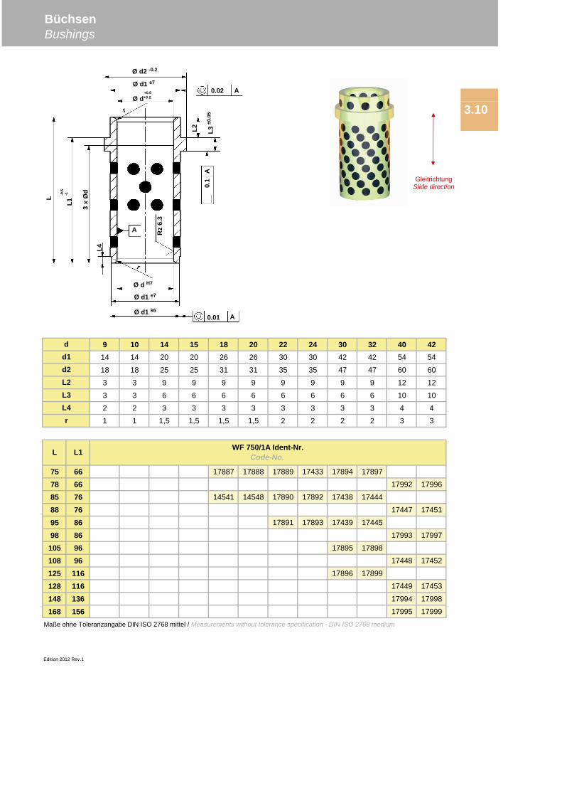
9 10 14 15 18 20 22 24 30 32 40 4214 14 20 20 26 26 30 30 42 42 54 54
18 18 25 25 31 31 35 35 47 47 60 60
3 3 9 9 9 9 9 9 9 9 12 12
3 3 6 6 6 6 6 6 6 6 10 10
2 2 3 3 3 3 3 3 3 3 4 4
1 1 1,5 1,5 1,5 1,5 2 2 2 2 3 3
75 66 17887 17888 17889 17433 17894 17897
78 66 17992 17996
85 76 14541 14548 17890 17892 17438 17444
88 76 17447 17451
95 86 17891 17893 17439 17445
98 86 17993 17997
105 96 17895 17898
108 96 17448 17452
125 116 17896 17899
128 116 17449 17453
148 136 17994 17998
168 156 17995 17999
d
WF 750/1A Ident-Nr.Code-No.
Edition 2012 Rev.1
L L1
d1d2L2L3L4r
Maße ohne Toleranzangabe DIN ISO 2768 mittel / Measurements without tolerance specification - DIN ISO 2768 medium
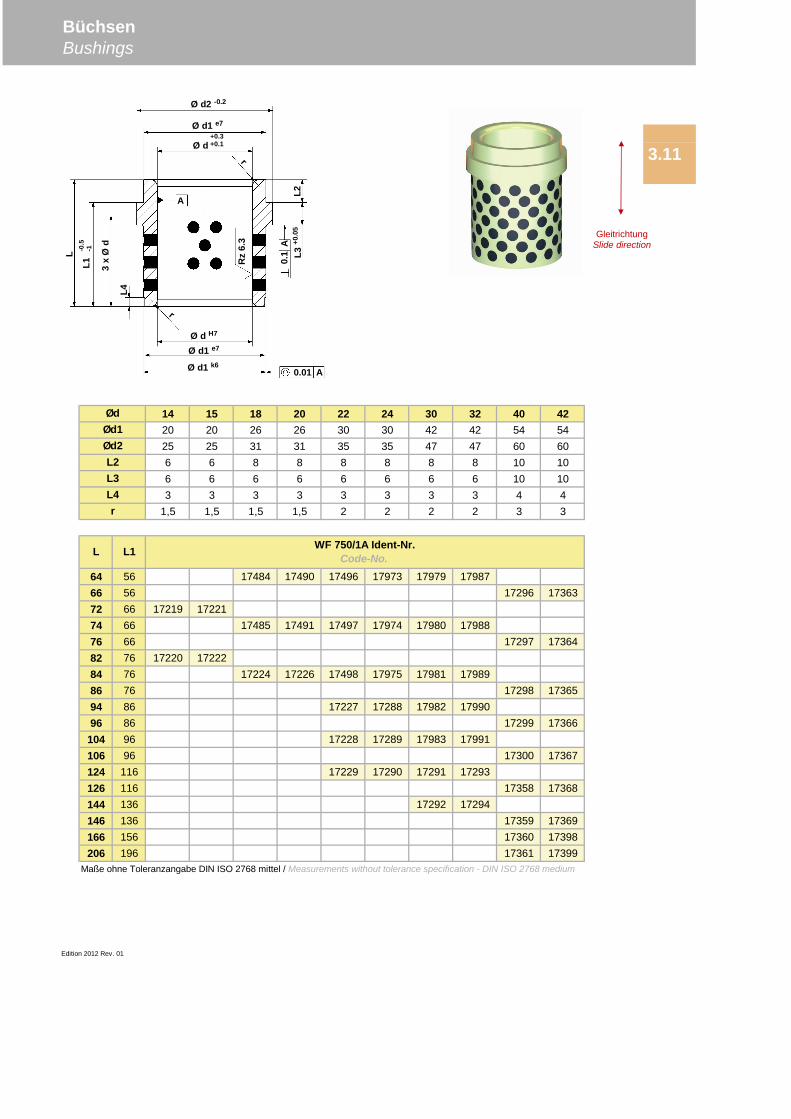
BüchsenBushings
3.10
Ø d2 -0.2
Ø d1 e7
Ø d+0.5+0.2
Ø d H7
Ø d1 e7
Ø d1 k60.01 A
A
A Rz
6.3
3x
Ød
L1-0
.5-1
L
0.1
L3±0
.05
0.02 A
L2
L4
GleitrichtungSlide direction
9 10 14 15 18 20 22 24 30 32 40 4214 14 20 20 26 26 30 30 42 42 54 5416 16 25 25 31 31 35 35 47 47 60 605 5 6 6 8 8 8 8 8 8 10 103 3 6 6 6 6 6 6 6 6 10 102 2 3 3 3 3 3 3 3 3 3 31 1 1,5 1,5 1,5 1,5 2 2 2 2 3 3
17 12 17213 1721622 17 17460 1746423 17 17468 1747425 17 17223 1722527 22 17461 1746528 22 17469 1747530 22 17480 17486 17492 1749932 27 17462 1746633 27 17470 1747635 27 17481 17487 17493 17970 17976 1798441 36 17463 1746742 36 17471 1747744 36 17482 17488 17494 17971 17977 1798551 46 17214 1721752 46 17472 1747854 46 17483 17489 17495 17972 17978 1798656 46 17295 1736261 56 17215 1721862 56 17473 17479
Edition 2012 Rev.1
WF 750/1A Ident-Nr.Code-No.L L1
ØdØd1Ød2L2L3
Maße ohne Toleranzangabe DIN ISO 2768 mittel / Measurements without tolerance specification - DIN ISO 2768 medium
L4r
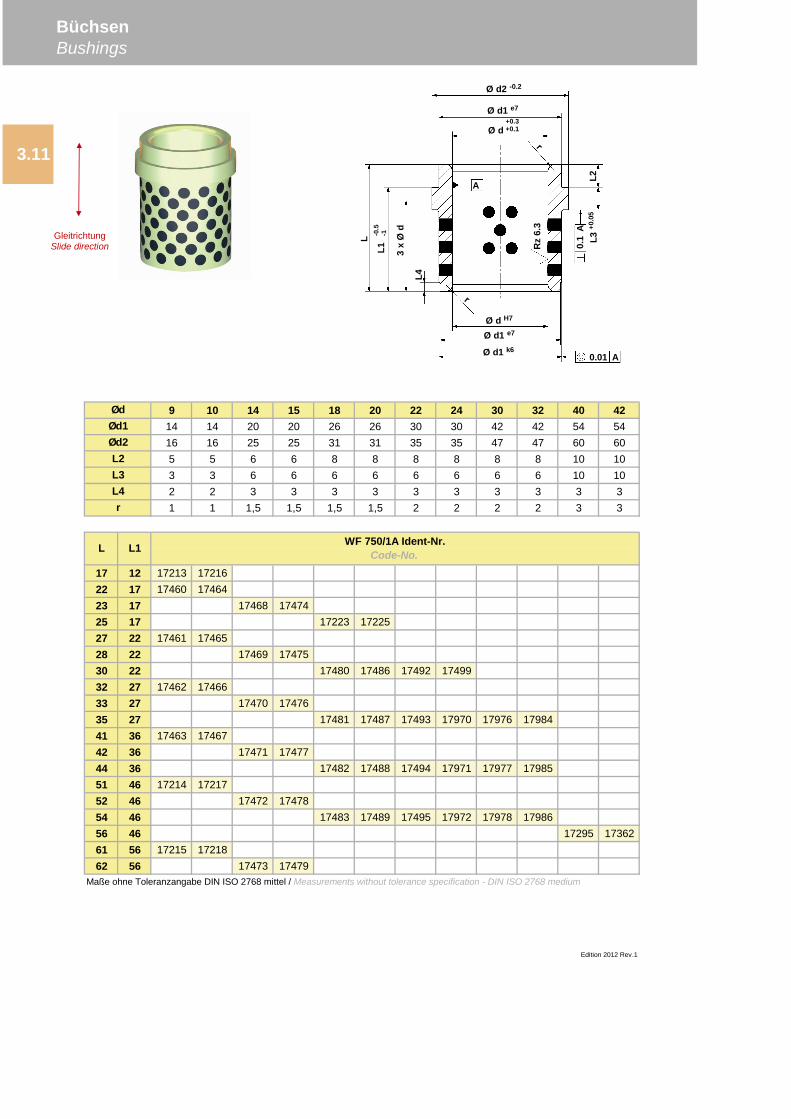
BüchsenBushings
3.11
GleitrichtungSlide direction
Ø d2 -0.2
Ø d1 e7
+0.3+0.1Ø d
Ø d H7
Ø d1 e7
Ø d1 k6
-0.5
-1L1 3
xØ
d
L
L2L3
+0.0
5
0.01 A
0.1
A
Rz
6.3
L4
A
14 15 18 20 22 24 30 32 40 4220 20 26 26 30 30 42 42 54 5425 25 31 31 35 35 47 47 60 606 6 8 8 8 8 8 8 10 106 6 6 6 6 6 6 6 10 103 3 3 3 3 3 3 3 4 4
1,5 1,5 1,5 1,5 2 2 2 2 3 3
64 56 17484 17490 17496 17973 17979 1798766 56 17296 1736372 66 17219 1722174 66 17485 17491 17497 17974 17980 1798876 66 17297 1736482 76 17220 1722284 76 17224 17226 17498 17975 17981 1798986 76 17298 1736594 86 17227 17288 17982 1799096 86 17299 17366
104 96 17228 17289 17983 17991106 96 17300 17367124 116 17229 17290 17291 17293126 116 17358 17368144 136 17292 17294146 136 17359 17369166 156 17360 17398206 196 17361 17399
Edition 2012 Rev. 01
L4r
ØdØd1Ød2L2L3
L L1 WF 750/1A Ident-Nr.Code-No.
Maße ohne Toleranzangabe DIN ISO 2768 mittel / Measurements without tolerance specification - DIN ISO 2768 medium
BüchsenBushings
3.11
GleitrichtungSlide direction
Ø d2 -0.2
Ø d1 e7
+0.3+0.1Ø d
Ø d H7
Ø d1 e7
Ø d1 k6
-0.5
-1L1 3
xØ
d
L
L2L3
+0.0
5
0.01 A
0.1
A
Rz
6.3
L4
A
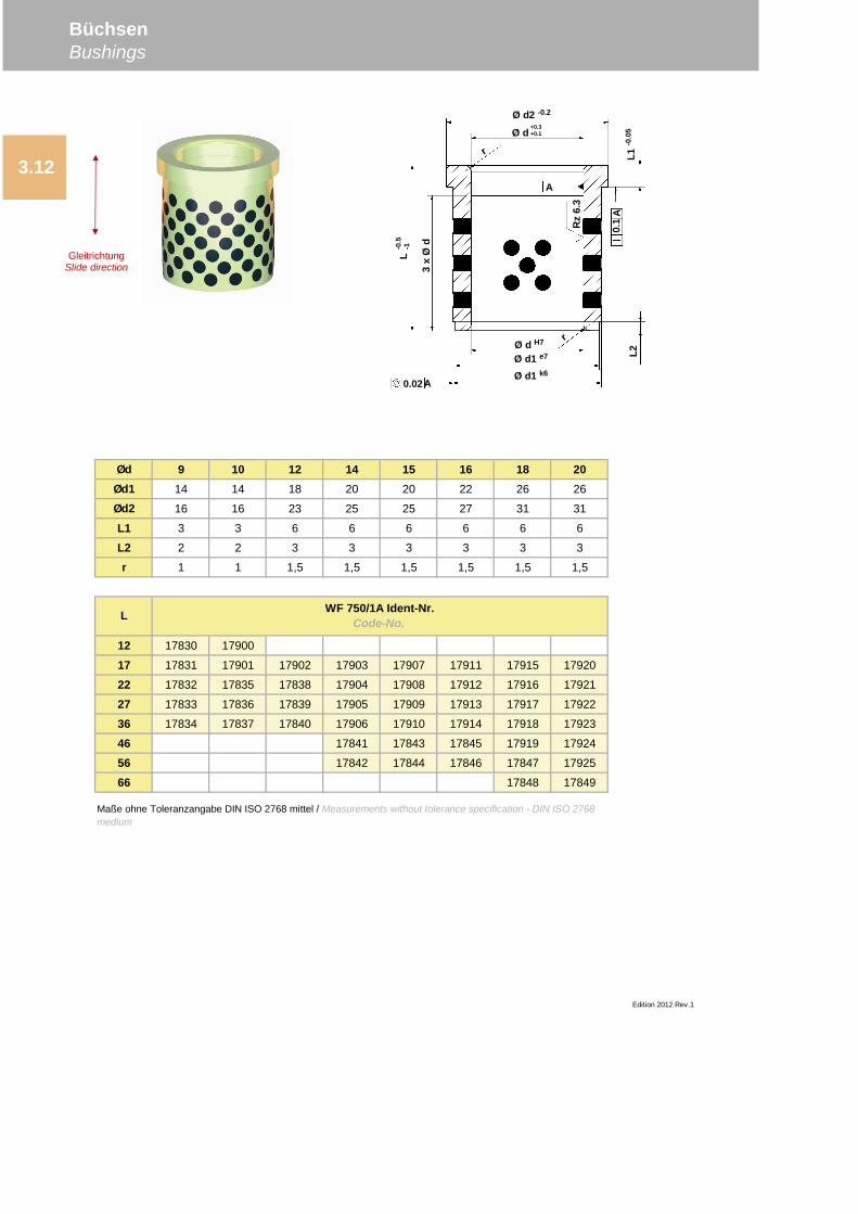
Ød 9 10 12 14 15 16 18 20Ød1 14 14 18 20 20 22 26 26
Ød2 16 16 23 25 25 27 31 31
L1 3 3 6 6 6 6 6 6
L2 2 2 3 3 3 3 3 3
r 1 1 1,5 1,5 1,5 1,5 1,5 1,5
12 17830 17900
17 17831 17901 17902 17903 17907 17911 17915 17920
22 17832 17835 17838 17904 17908 17912 17916 17921
27 17833 17836 17839 17905 17909 17913 17917 17922
36 17834 17837 17840 17906 17910 17914 17918 17923
46 17841 17843 17845 17919 17924
56 17842 17844 17846 17847 17925
66 17848 17849
Edition 2012 Rev.1
L WF 750/1A Ident-Nr.Code-No.
Maße ohne Toleranzangabe DIN ISO 2768 mittel / Measurements without tolerance specification - DIN ISO 2768medium
BüchsenBushings
3.12
Ø d2 -0.2
Ø d+0.3+0.1
Ø d H7
Ø d1 e7
Ø d1 k6
L-0
.5-1
3x
Ød
L2
0.02A
0.1
AL1
-0.0
5
A
Rz
6.3
GleitrichtungSlide direction
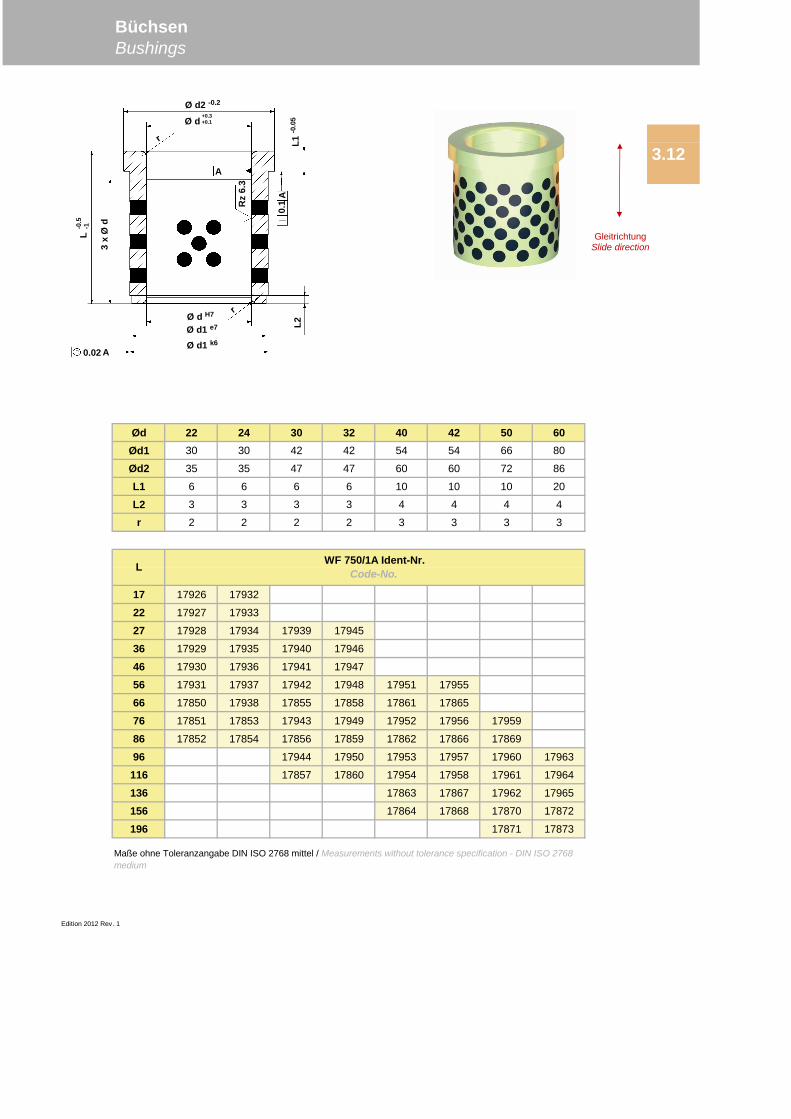
Ød 22 24 30 32 40 42 50 60Ød1 30 30 42 42 54 54 66 80
Ød2 35 35 47 47 60 60 72 86
L1 6 6 6 6 10 10 10 20
L2 3 3 3 3 4 4 4 4
r 2 2 2 2 3 3 3 3
17 17926 17932
22 17927 17933
27 17928 17934 17939 17945
36 17929 17935 17940 17946
46 17930 17936 17941 17947
56 17931 17937 17942 17948 17951 17955
66 17850 17938 17855 17858 17861 17865
76 17851 17853 17943 17949 17952 17956 17959
86 17852 17854 17856 17859 17862 17866 17869
96 17944 17950 17953 17957 17960 17963
116 17857 17860 17954 17958 17961 17964
136 17863 17867 17962 17965
156 17864 17868 17870 17872
196 17871 17873
Edition 2012 Rev. 1
Maße ohne Toleranzangabe DIN ISO 2768 mittel / Measurements without tolerance specification - DIN ISO 2768medium
BüchsenBushings
3.12
L WF 750/1A Ident-Nr.Code-No.
GleitrichtungSlide direction
Ø d2 -0.2
Ø d+0.3+0.1
Ø d H7
Ø d1 e7
Ø d1 k6
L-0
.5-1
3x
Ød
L2
0.02 A
0.1
AL1
-0.0
5
A
Rz
6.3
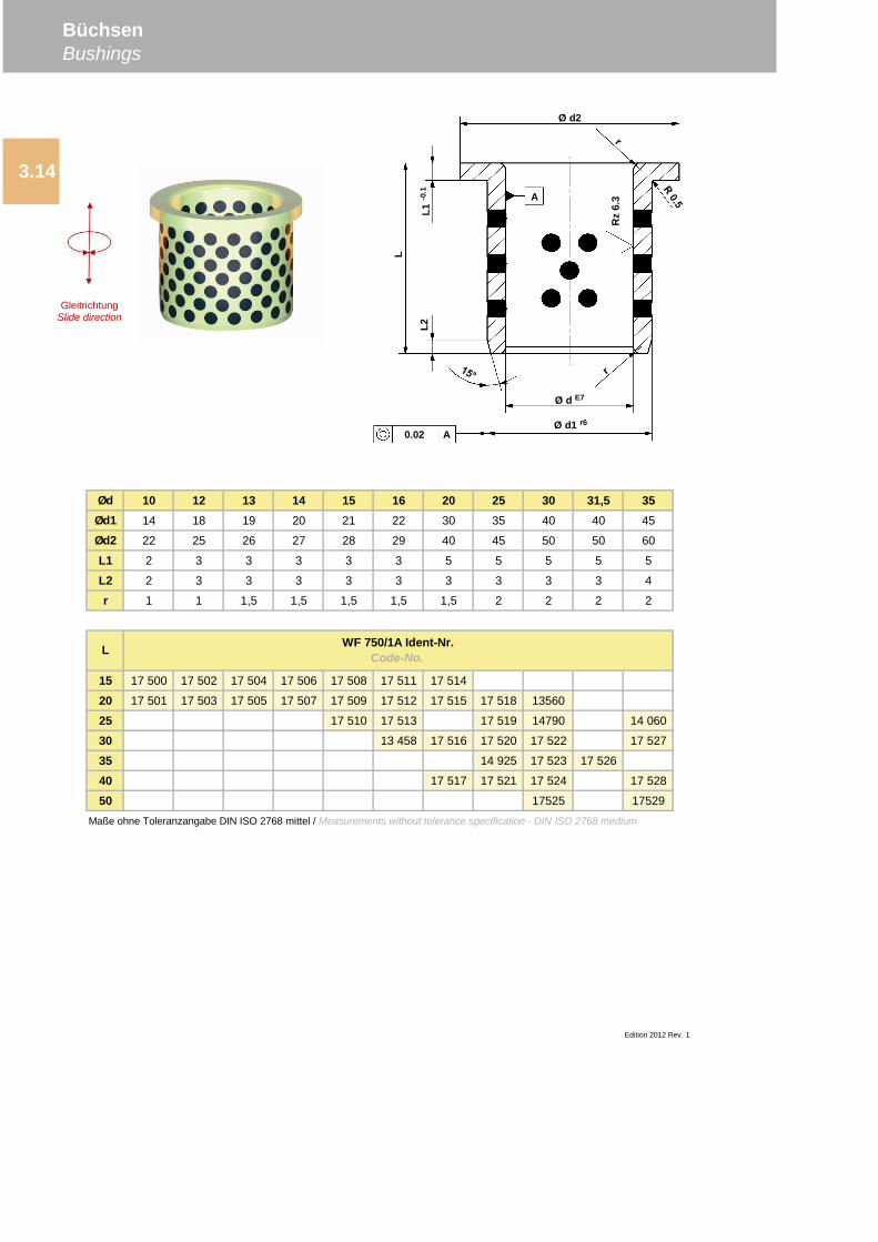
Ød 10 12 13 14 15 16 20 25 30 31,5 35Ød1 14 18 19 20 21 22 30 35 40 40 45
Ød2 22 25 26 27 28 29 40 45 50 50 60
L1 2 3 3 3 3 3 5 5 5 5 5
L2 2 3 3 3 3 3 3 3 3 3 4
r 1 1 1,5 1,5 1,5 1,5 1,5 2 2 2 2
15 17 500 17 502 17 504 17 506 17 508 17 511 17 514
20 17 501 17 503 17 505 17 507 17 509 17 512 17 515 17 518 13560
25 17 510 17 513 17 519 14790 14 060
30 13 458 17 516 17 520 17 522 17 527
35 14 925 17 523 17 526
40 17 517 17 521 17 524 17 528
50 17525 17529
Edition 2012 Rev. 1
WF 750/1A Ident-Nr.Code-No.L
Maße ohne Toleranzangabe DIN ISO 2768 mittel / Measurements without tolerance specification - DIN ISO 2768 medium
BüchsenBushings
3.14A
GleitrichtungSlide direction
Ø d2
Ø d E7
Ø d1 r60.02 A
L2L1
-0.1
L
Rz
6.3A
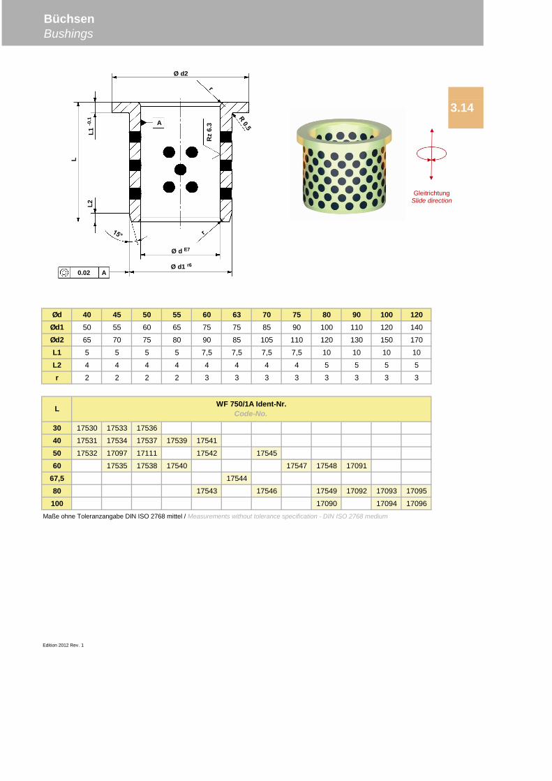
Ød 40 45 50 55 60 63 70 75 80 90 100 120Ød1 50 55 60 65 75 75 85 90 100 110 120 140
Ød2 65 70 75 80 90 85 105 110 120 130 150 170
L1 5 5 5 5 7,5 7,5 7,5 7,5 10 10 10 10
L2 4 4 4 4 4 4 4 4 5 5 5 5
r 2 2 2 2 3 3 3 3 3 3 3 3
30 17530 17533 17536
40 17531 17534 17537 17539 17541
50 17532 17097 17111 17542 17545
60 17535 17538 17540 17547 17548 17091
67,5 17544
80 17543 17546 17549 17092 17093 17095
100 17090 17094 17096
Edition 2012 Rev. 1
L WF 750/1A Ident-Nr.Code-No.
Maße ohne Toleranzangabe DIN ISO 2768 mittel / Measurements without tolerance specification - DIN ISO 2768 medium
BüchsenBushings
3.14
GleitrichtungSlide direction
Ø d2
Ø d E7
Ø d1 r60.02 A
L2L1
-0.1
L
Rz
6.3A
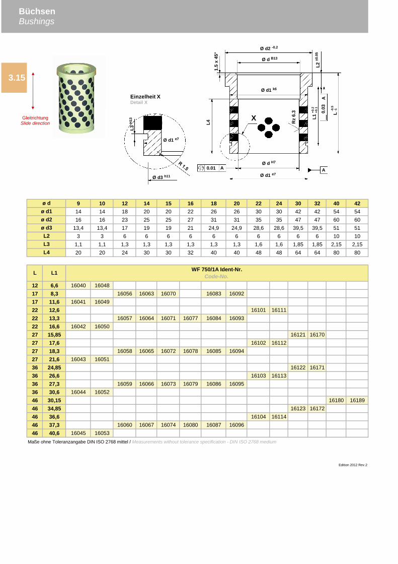
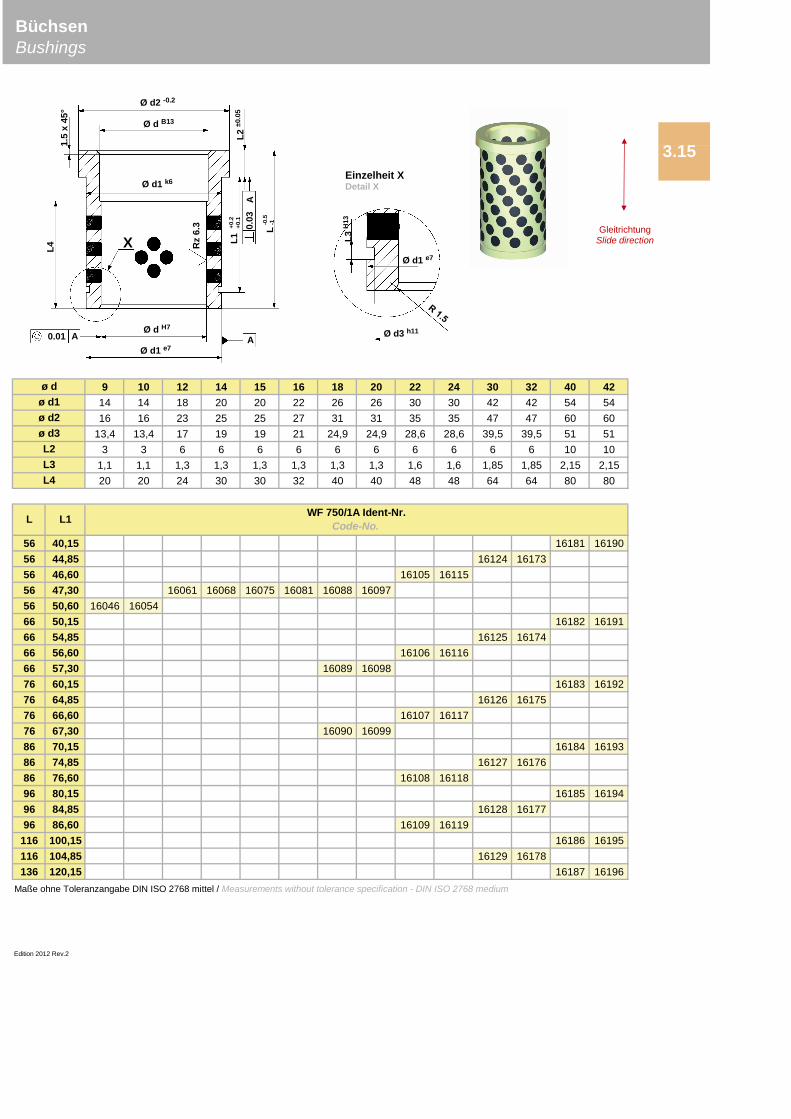
9 10 12 14 15 16 18 20 22 24 30 32 40 4214 14 18 20 20 22 26 26 30 30 42 42 54 5416 16 23 25 25 27 31 31 35 35 47 47 60 60
13,4 13,4 17 19 19 21 24,9 24,9 28,6 28,6 39,5 39,5 51 513 3 6 6 6 6 6 6 6 6 6 6 10 10
1,1 1,1 1,3 1,3 1,3 1,3 1,3 1,3 1,6 1,6 1,85 1,85 2,15 2,1520 20 24 30 30 32 40 40 48 48 64 64 80 80
12 6,6 16040 1604817 8,3 16056 16063 16070 16083 1609217 11,6 16041 1604922 12,6 16101 1611122 13,3 16057 16064 16071 16077 16084 1609322 16,6 16042 1605027 15,85 16121 1617027 17,6 16102 1611227 18,3 16058 16065 16072 16078 16085 1609427 21,6 16043 1605136 24,85 16122 1617136 26,6 16103 1611336 27,3 16059 16066 16073 16079 16086 1609536 30,6 16044 1605246 30,15 16180 1618946 34,85 16123 1617246 36,6 16104 1611446 37,3 16060 16067 16074 16080 16087 1609646 40,6 16045 16053
3.15
Edition 2012 Rev.2
L4
WF 750/1A Ident-Nr.Code-No.L L1
Maße ohne Toleranzangabe DIN ISO 2768 mittel / Measurements without tolerance specification - DIN ISO 2768 medium
L3
ø dø d1ø d2ø d3L2
Ø d2 -0.2
Ø d B13
Ø d H7
Ø d1 e70.01 A A
A0.
03
L4
L+0.2
+0.1
L1
-0.5
-1
L2±0
.05
1.5
x45
°
Ø d1 k6
Rz
6.3
GleitrichtungSlide direction
X
L3H
13
Ø d3 h11
Einzelheit XDetail X
Ø d1 e7
BüchsenBushings
9 10 12 14 15 16 18 20 22 24 30 32 40 4214 14 18 20 20 22 26 26 30 30 42 42 54 5416 16 23 25 25 27 31 31 35 35 47 47 60 60
13,4 13,4 17 19 19 21 24,9 24,9 28,6 28,6 39,5 39,5 51 513 3 6 6 6 6 6 6 6 6 6 6 10 10
1,1 1,1 1,3 1,3 1,3 1,3 1,3 1,3 1,6 1,6 1,85 1,85 2,15 2,1520 20 24 30 30 32 40 40 48 48 64 64 80 80
56 40,15 16181 1619056 44,85 16124 1617356 46,60 16105 1611556 47,30 16061 16068 16075 16081 16088 1609756 50,60 16046 1605466 50,15 16182 1619166 54,85 16125 1617466 56,60 16106 1611666 57,30 16089 1609876 60,15 16183 1619276 64,85 16126 1617576 66,60 16107 1611776 67,30 16090 1609986 70,15 16184 1619386 74,85 16127 1617686 76,60 16108 1611896 80,15 16185 1619496 84,85 16128 1617796 86,60 16109 16119
116 100,15 16186 16195116 104,85 16129 16178136 120,15 16187 16196
Edition 2012 Rev.2
BüchsenBushings
3.15
ø dø d1ø d2ø d3L2
Maße ohne Toleranzangabe DIN ISO 2768 mittel / Measurements without tolerance specification - DIN ISO 2768 medium
L3L4
L L1 WF 750/1A Ident-Nr.Code-No.
GleitrichtungSlide directionL3
H13
Ø d3 h11
Einzelheit XDetail X
Ø d1 e7
Ø d2 -0.2
Ø d B13
Ø d H7
Ø d1 e70.01 A A
A0.
03
L4
L+0.2
+0.1
L1
-0.5
-1
L2±0
.05
1.5
x45
°
Ø d1 k6
X Rz
6.3

Edition 2012 Rev.0
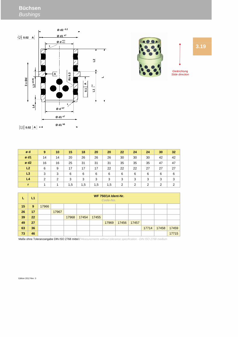
9 10 15 18 20 20 22 24 24 30 3214 14 20 26 26 26 30 30 30 42 42
16 16 25 31 31 31 35 35 35 47 47
6 9 17 17 17 22 22 22 27 27 27
3 3 6 6 6 6 6 6 6 6 6
2 2 3 3 3 3 3 3 3 3 3
1 1 1,5 1,5 1,5 1,5 2 2 2 2 2
15 9 17966
26 17 17967
39 22 17968 17454 17455
49 27 17969 17456 17457
63 36 17714 17458 17459
73 46 17715
Edition 2012 Rev. 0
ø dø d1ø d2
BüchsenBushings
3.19
L2L3
Maße ohne Toleranzangabe DIN ISO 2768 mittel / Measurements without tolerance specification - DIN ISO 2768 medium
r
WF 750/1A Ident-Nr.Code-No.L L1
L4
Ø d2 -0.2
Ø d1 e7
Ø d +0.3+0.1
Ø d H7
Ø d1 e7
0.02 A
A
A0.
1
3x
Ød
L3±0
.05
L1-0
.5-1
L2
L
0.02 AL4
Rz
6.3
Ø d1 k6
GleitrichtungSlide direction
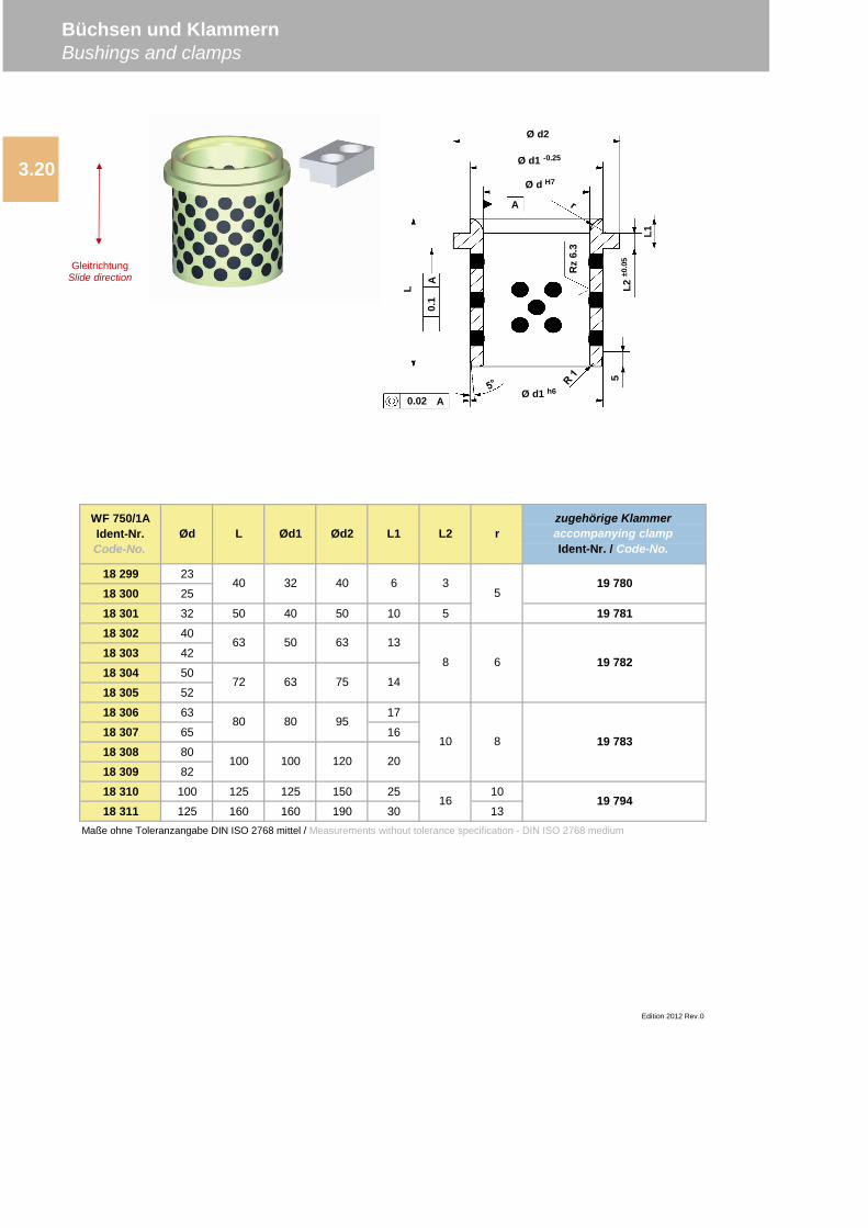
18 299 23
18 300 25
18 301 32 50 40 50 10 5 19 78118 302 40
18 303 42
18 304 50
18 305 52
18 306 63 17
18 307 65 16
18 308 80
18 309 82
18 310 100 125 125 150 25 10
18 311 125 160 160 190 30 13
100 100
80
40 32 40 6
63 50
80
Edition 2012 Rev.0
13
14
20
35
68
10 8
19 780
19 782
19 783
19 79416
Maße ohne Toleranzangabe DIN ISO 2768 mittel / Measurements without tolerance specification - DIN ISO 2768 medium
L2WF 750/1AIdent-Nr.Code-No.
Ød L Ød1 Ød2 L1
63
63
75
95
120
rzugehörige Klammeraccompanying clampIdent-Nr. / Code-No.
Büchsen und KlammernBushings and clamps
3.20
72
A
A0.02
Ø d2
Ø d1 -0.25
Ø d H7
Ø d1 h6
L2±0
.05
L1
Rz
6.3
5
L
A0.
1
GleitrichtungSlide direction
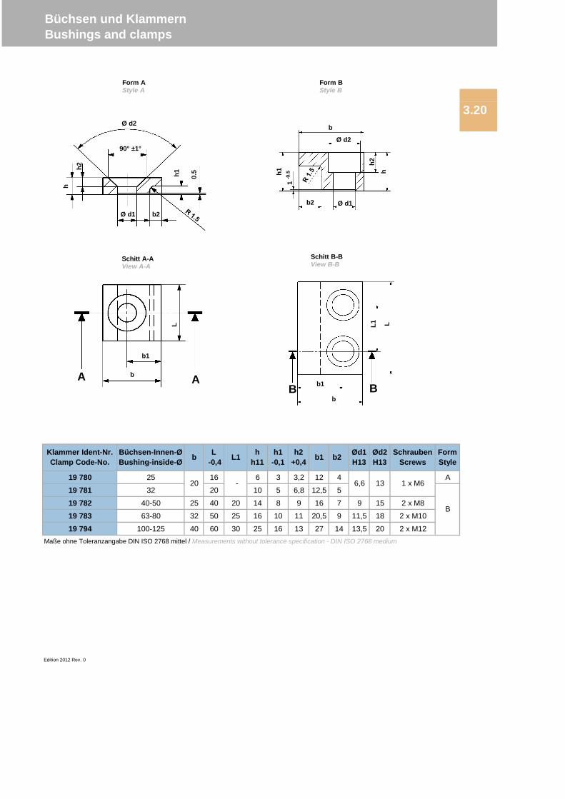
19 780 25 16 6 3 3,2 12 4 A
19 781 32 20 10 5 6,8 12,5 5
19 782 40-50 25 40 20 14 8 9 16 7 9 15 2 x M8
19 783 63-80 32 50 25 16 10 11 20,5 9 11,5 18 2 x M10
19 794 100-125 40 60 30 25 16 13 27 14 13,5 20 2 x M12
Edition 2012 Rev. 0
1 x M6136,6 -
b2 Ød1H13
Ød2H13
hh11
h1-0,1
h2+0,4 b1
Maße ohne Toleranzangabe DIN ISO 2768 mittel / Measurements without tolerance specification - DIN ISO 2768 medium
Büchsen und KlammernBushings and clamps
3.20
Klammer Ident-Nr.Clamp Code-No.
Büchsen-Innen-ØBushing-inside-Ø b L
-0,4 L1
20
B
FormStyle
SchraubenScrews
Ø d2
Ø d1
h
h2
90° ±1°
h1
b2
0.5
b1
b
L
A A b1
b
L1 LB B
b2
Ø d2
Ø d1
h1
h2
h
1-0
.5
b
Schitt A-AView A-A
Schitt B-BView B-B
Form AStyle A
Form BStyle B

Büchsen mit AnlaufbundBushings with buffer flange4.1
Büchsen mit AnlaufbundBushings with buffer flangeWF 750
4

Edition 2012 Rev. 0
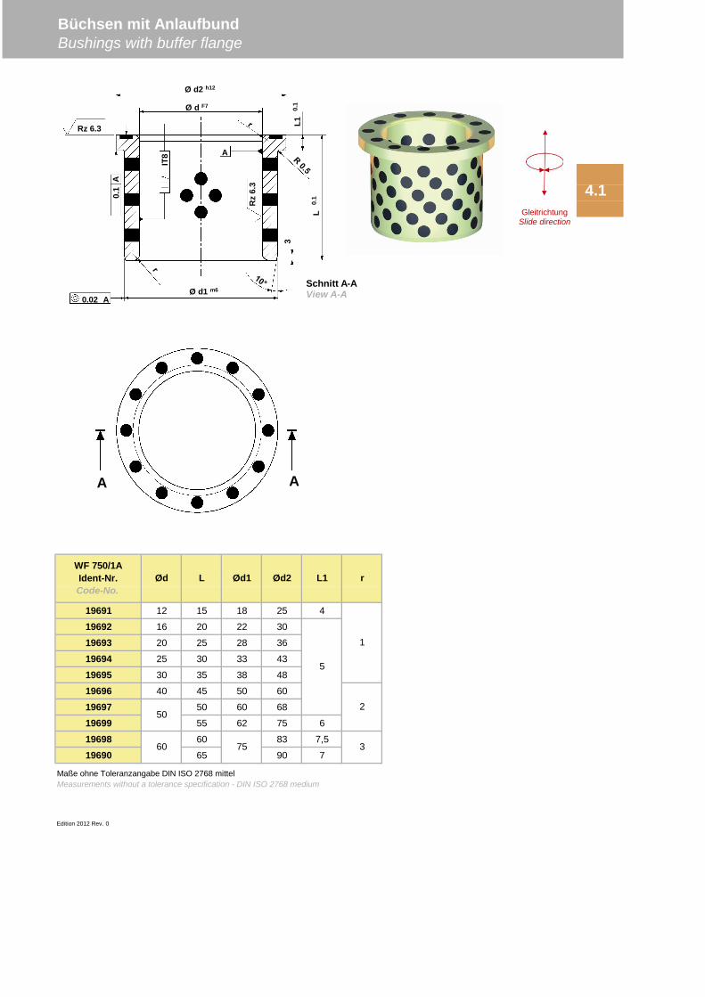
19691 12 15 18 25 4
19692 16 20 22 30
19693 20 25 28 36
19694 25 30 33 43
19695 30 35 38 48
19696 40 45 50 60
19697 50 60 68
19699 55 62 75 6
19698 60 83 7,5
19690 65 90 7
Edition 2012 Rev. 0
Maße ohne Toleranzangabe DIN ISO 2768 mittelMeasurements without a tolerance specification - DIN ISO 2768 medium
WF 750/1AIdent-Nr.Code-No.
Ød L Ød1 Ød2 L1 r
5
1
2
375
50
60
4.1
Büchsen mit AnlaufbundBushings with buffer flange
A A
Ø d2 h12
Ø d F7
Ø d1 m6
0.02 A
A
A
0.1
IT8
3L1
0.1
L0.
1
Rz 6.3
Rz
6.3
Schnitt A-AView A-A
GleitrichtungSlide direction

AnlaufscheibenWashersWF 750
6
6.1 AnlaufscheibenWashers

Edition 2012 Rev. 0
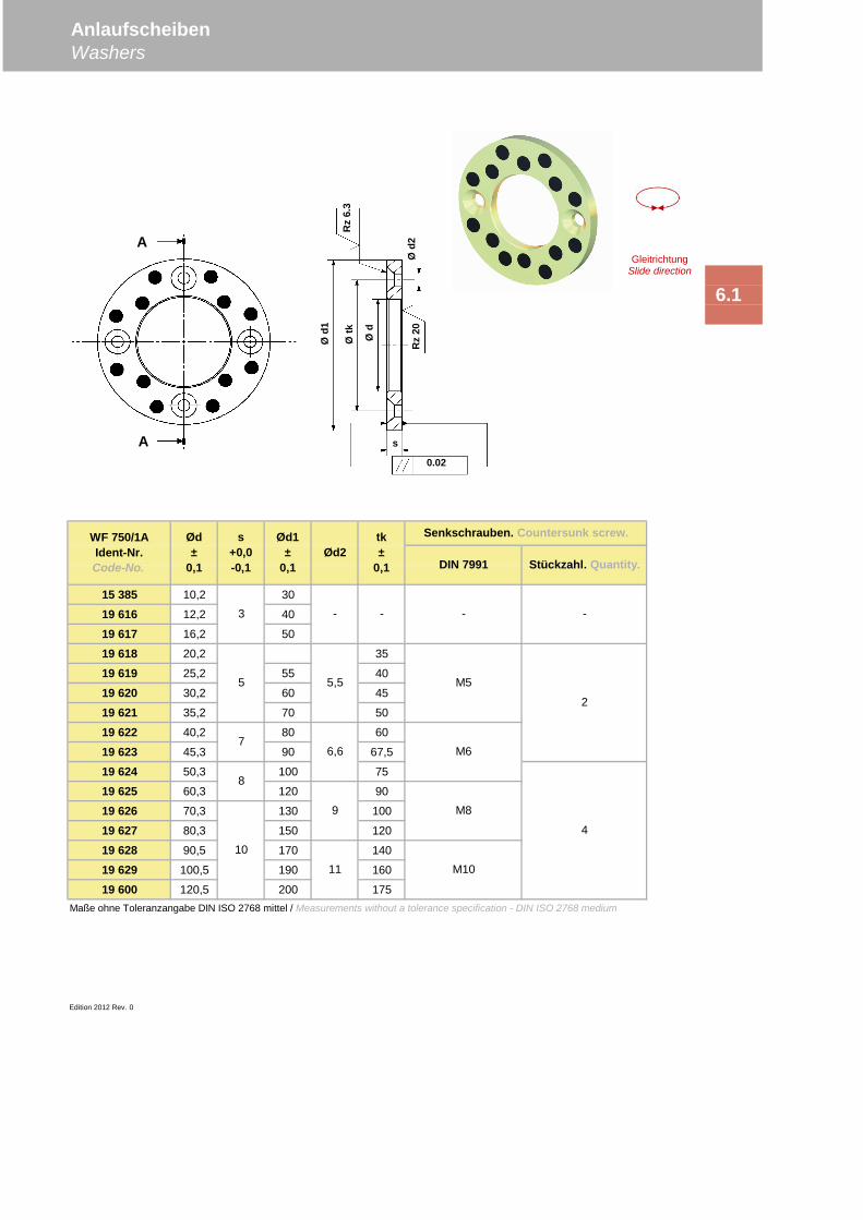
15 385 10,2 30
19 616 12,2 40
19 617 16,2 50
19 618 20,2 35
19 619 25,2 55 40
19 620 30,2 60 45
19 621 35,2 70 50
19 622 40,2 80 60
19 623 45,3 90 67,5
19 624 50,3 100 75
19 625 60,3 120 90
19 626 70,3 130 100
19 627 80,3 150 120
19 628 90,5 170 140
19 629 100,5 190 160
19 600 120,5 200 175Maße ohne Toleranzangabe DIN ISO 2768 mittel / Measurements without a tolerance specification - DIN ISO 2768 medium
Edition 2012 Rev. 0
AnlaufscheibenWashers
6.1
WF 750/1AIdent-Nr.Code-No.
Ød±
0,1
s+0,0-0,1
Ød1±
0,1Ød2
tk±
0,1
Senkschrauben. Countersunk screw.
-3 - - -
DIN 7991 Stückzahl. Quantity.
9
6,6
11
5,55
7
8
10
M5
M6
M8
M10
2
4
s
Ød2
Ød1
Øtk
Ød
Rz
6.3
Rz
20
A
A0.02
GleitrichtungSlide direction
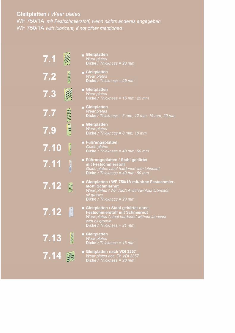
Gleitplatten
Wear plates
Wear plates
Wear plates
Wear plates
Guide plates
mit FestschmierstoffGuide plates steel hardened with lubricant
Gleitplatten / WF 750/1A mit/ohne Festschmier-stoff, SchmiernutWear plates / WF 750/1A with/wihtout lubricantoil groove
Festschmierstoff mit SchmiernutWear plates / steel hardened without lubricantwith oil groove
Wear plates
Wear plates acc. To VDI 3357
Dicke / Thickness = 8 mm; 12 mm; 16 mm; 20 mm
7.13 Gleitplatten
Dicke / Thickness = 16 mm
7.14 Gleitplatten nach VDI 3357
Dicke / Thickness = 20 mm
7.12Dicke / Thickness = 20 mm
7.12 Gleitplatten / Stahl gehärtet ohne
Dicke / Thickness = 21 mm
7.10Führungsplatten
Dicke / Thickness = 40 mm; 50 mm
7.11 Führungsplatten / Stahl gehärtet
Dicke / Thickness = 40 mm; 50 mm
7.7Gleitplatten
7.9Gleitplatten
Dicke / Thickness = 8 mm; 10 mm
7.2 Gleitplatten
Dicke / Thickness = 20 mm
7.3 Gleitplatten
Dicke / Thickness = 16 mm; 25 mm
7.1 Wear platesDicke / Thickness = 20 mm
Gleitplatten / Wear platesWF 750/1A mit Festschmierstoff, wenn nichts anderes angegebenWF 750/1A with lubricant, if not other mentioned
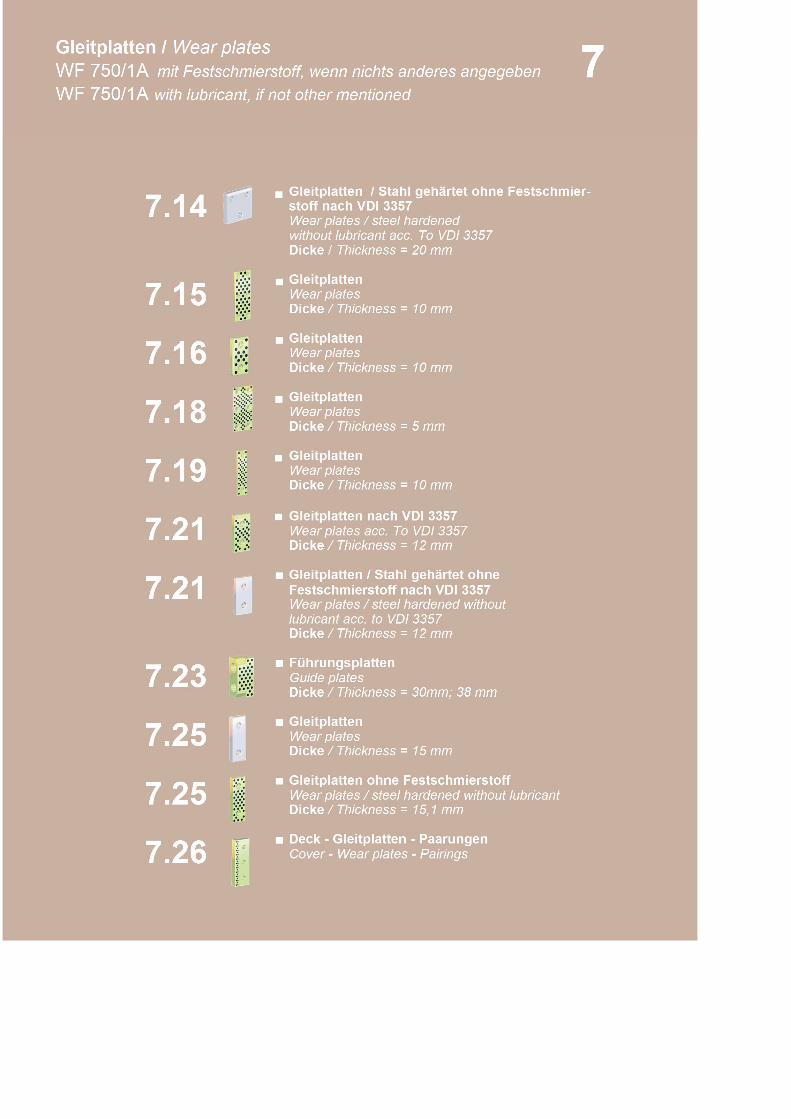
Gleitplatten / Stahl gehärtet ohne Festschmier-
Wear plates
Wear plates
Wear plates
Wear plates
Wear plates acc. To VDI 3357
Festschmierstoff nach VDI 3357Wear plates / steel hardened withoutlubricant acc. to VDI 3357
Guide plates
Wear plates
Wear plates / steel hardened without lubricant
Cover - Wear plates - Pairings
Dicke / Thickness = 20 mm
Dicke / Thickness = 10 mm
Gleitplatten
Gleitplatten
Dicke / Thickness = 5 mm
7.26
7.25Deck - Gleitplatten - Paarungen
Dicke / Thickness = 10 mm
Gleitplatten nach VDI 3357
Dicke / Thickness = 12 mm
Gleitplatten / Stahl gehärtet ohne
Dicke / Thickness = 12 mm
Führungsplatten
Dicke / Thickness = 30mm; 38 mm
Gleitplatten
Dicke / Thickness = 15 mm
Gleitplatten ohne Festschmierstoff
Dicke / Thickness = 15,1 mm
7.25
7.15
7.18
7.21
7.23
7.16
7.21
7
7.19
Dicke / Thickness = 10 mm
Gleitplatten
Gleitplatten
7.14 Wear plates / steel hardenedstoff nach VDI 3357
without lubricant acc. To VDI 3357
Gleitplatten / Wear platesWF 750/1A mit Festschmierstoff, wenn nichts anderes angegebenWF 750/1A with lubricant, if not other mentioned
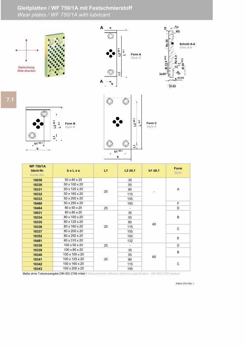
18030 50 x 80 x 20 3518330 50 x 100 x 20 5518331 50 x 125 x 20 8018332 50 x 160 x 20 11518333 50 x 200 x 20 15518480 50 x 250 x 20 100 F18484 80 x 50 x 20 25 - D18031 80 x 80 x 20 3518334 80 x 100 x 20 5518335 80 x 125 x 20 8018336 80 x 160 x 20 11518337 80 x 200 x 20 15518352 80 x 250 x 20 10018481 80 x 315 x 20 13218338 100 x 50 x 20 25 - D18339 100 x 80 x 20 3518340 100 x 100 x 20 5518341 100 x 125 x 20 8018342 100 x 160 x 20 11518343 100 x 200 x 20 155
7.1
Gleitplatten / WF 750/1A mit FestschmierstoffWear plates / WF 750/1A with lubricant
WF 750/1AIdent-Nr.Code-No.
b x L x s L2 ±0,1 b1 ±0,1 FormStyle
20 -A
L1
Maße ohne Toleranzangabe DIN ISO 2768 mittel / Measurements without a tolerance specification - DIN ISO 2768 medium
Edition 2012 Rev. 1
4020
B
C
E
6020
B
C
s ±0.025
0.02
13+0.5+0
Ø20
H13
Rz
6.3
Rz
20Ø
13.5
H13
10
3x45°
A
L-0
.1
L2±0
.1
Ab
L1
b
b1 ±0.1
L2±0
.1
L-0
.1
L1
b1 ±0.1
b
L2±0
.1
L-0
.1
L1Form AStyle A
Schnitt A-AView A-A
Form BStyle B
Form CStyle C
GleitrichtungSlide direction
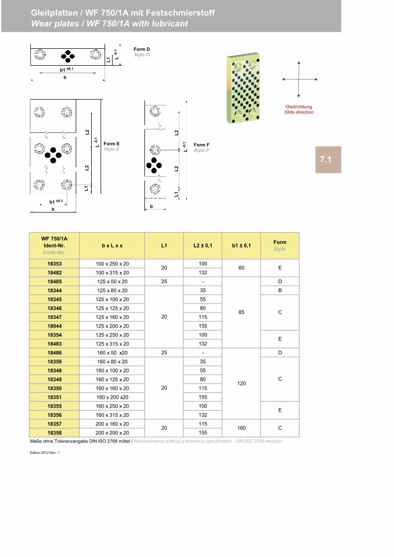
18353 100 x 250 x 20 100
18482 100 x 315 x 20 132
18485 125 x 50 x 20 25 - D
18344 125 x 80 x 20 35 B
18345 125 x 100 x 20 55
18346 125 x 125 x 20 80
18347 125 x 160 x 20 115
18044 125 x 200 x 20 155
18354 125 x 250 x 20 100
18483 125 x 315 x 20 132
18486 160 x 50 x20 25 - D
18359 160 x 80 x 20 35
18348 160 x 100 x 20 55
18349 160 x 125 x 20 80
18350 160 x 160 x 20 115
18351 160 x 200 x20 155
18355 160 x 250 x 20 100
18356 160 x 315 x 20 132
18357 200 x 160 x 20 115
18358 200 x 200 x 20 155
Edition 2012 Rev. 1
Gleitplatten / WF 750/1A mit FestschmierstoffWear plates / WF 750/1A with lubricant
7.1
FormStyle
WF 750/1AIdent-Nr.Code-No.
b x L x s L1 L2 ± 0,1 b1 ± 0,1
Maße ohne Toleranzangabe DIN ISO 2768 mittel / Measurements without a tolerance specification - DIN ISO 2768 medium
E
C
E
C
E
C
20
20
20
20
60
85
120
160
bbb1 ±0.1
bb1 ±0.1
L-0
.1
L1
L1
L-0
.1L-0
.1
L1
L2L2
L2L2
Form DStyle D
Form FStyle F
Form EStyle E
GleitrichtungSlide direction
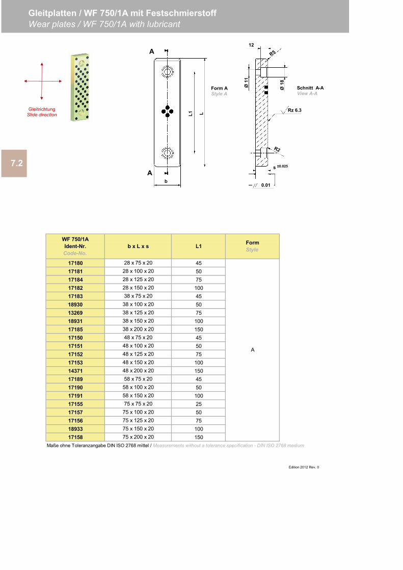
17180 28 x 75 x 20 4517181 28 x 100 x 20 5017184 28 x 125 x 20 7517182 28 x 150 x 20 10017183 38 x 75 x 20 4518930 38 x 100 x 20 5013269 38 x 125 x 20 7518931 38 x 150 x 20 10017185 38 x 200 x 20 15017150 48 x 75 x 20 4517151 48 x 100 x 20 5017152 48 x 125 x 20 7517153 48 x 150 x 20 10014371 48 x 200 x 20 15017189 58 x 75 x 20 4517190 58 x 100 x 20 5017191 58 x 150 x 20 10017155 75 x 75 x 20 2517157 75 x 100 x 20 5017156 75 x 125 x 20 7518933 75 x 150 x 20 10017158 75 x 200 x 20 150
7.2
Gleitplatten / WF 750/1A mit FestschmierstoffWear plates / WF 750/1A with lubricant
b x L x s L1 FormStyle
Edition 2012 Rev. 0
A
WF 750/1AIdent-Nr.Code-No.
Maße ohne Toleranzangabe DIN ISO 2768 mittel / Measurements without a tolerance specification - DIN ISO 2768 medium
bA
A
L1 L
Ø18Ø11
12
Rz 6.3
s ±0.025
0.01
Form AStyle A
Schnitt A-AView A-A
GleitrichtungSlide direction
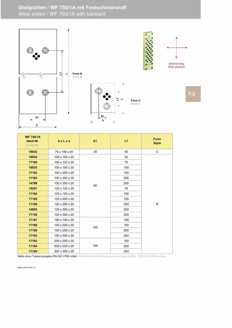
18932 75 x 100 x 20 25 50 C
18934 100 x 100 x 20 50
17160 100 x 125 x 20 75
18935 100 x 150 x 20 100
17162 100 x 200 x 20 150
17163 100 x 250 x 20 200
14799 100 x 300 x 20 200
15291 125 x 125 x 20 75
17164 125 x 150 x 20 100
17165 125 x 200 x 20 150
17166 125 x 250 x 20 200
14805 125 x 300 x 20 250
17159 125 x 350 x 20 200
17167 150 x 150 x 20 100
17168 150 x 200 x 20 150
17169 150 x 250 x 20 200
17192 150 x 300 x 20 250
17193 200 x 200 x 20 150
17194 200 x 250 x 20 200
17195 200 x 300 x 20 250
Edition 2012 Rev. 0
7.2
Gleitplatten / WF 750/1A mit FestschmierstoffWear plates / WF 750/1A with lubricant
WF 750/1AIdent-Nr.Code-No.
b x L x s b1 L1 FormStyle
B
50
100
150
Maße ohne Toleranzangabe DIN ISO 2768 mittel / Measurements without a tolerance specification - DIN ISO 2768 medium
LL1b1b
b1
b
L1 L Form BStyle B
Form CStyle C
GleitrichtungSlide direction
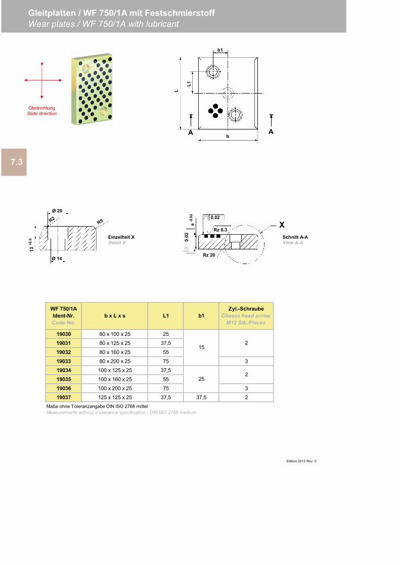
19030 80 x 100 x 25 25
19031 80 x 125 x 25 37,5
19032 80 x 160 x 25 55
19033 80 x 200 x 25 75 3
19034 100 x 125 x 25 37,5
19035 100 x 160 x 25 55
19036 100 x 200 x 25 75 3
19037 125 x 125 x 25 37,5 37,5 2
7.3
Gleitplatten / WF 750/1A mit FestschmierstoffWear plates / WF 750/1A with lubricant
Edition 2012 Rev. 0
252
Maße ohne Toleranzangabe DIN ISO 2768 mittelMeasurements without a tolerance specification - DIN ISO 2768 medium
152
WF 750/1AIdent-Nr.Code-No.
b x L x s L1 b1Zyl.-Schraube
Cheese head screwM12 Stk./Pieces
Schnitt A-AView A-A
Ø 14
Ø 20
13+0
.5
Einzelheit XDetail X
0.02
0.02
Rz 6.3
Rz 20
Xs-0
.02
b1
L1
L
A Ab
GleitrichtungSlide direction
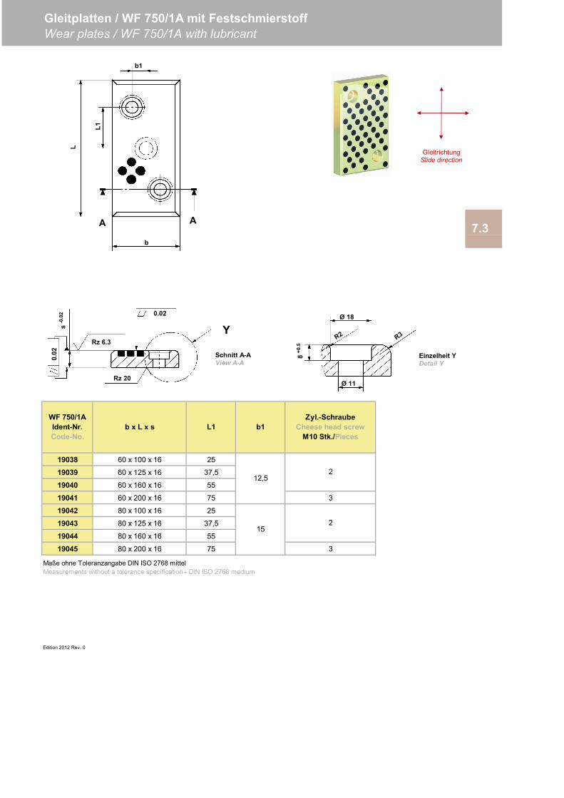
19038 60 x 100 x 16 25
19039 60 x 125 x 16 37,5
19040 60 x 160 x 16 55
19041 60 x 200 x 16 75 3
19042 80 x 100 x 16 25
19043 80 x 125 x 16 37,5
19044 80 x 160 x 16 55
19045 80 x 200 x 16 75 3
Edition 2012 Rev. 0
Gleitplatten / WF 750/1A mit FestschmierstoffWear plates / WF 750/1A with lubricant
7.3
15
2
2
Maße ohne Toleranzangabe DIN ISO 2768 mittelMeasurements without a tolerance specification - DIN ISO 2768 medium
WF 750/1AIdent-Nr.Code-No.
b x L x s L1 b1
12,5
Zyl.-SchraubeCheese head screw
M10 Stk./Pieces
0.02
0.02
Rz 6.3
Rz 20
Ys-0
.02 Ø 18
Ø 11
8+0
.5
b1
b
L1
L
A A
Schnitt A-AView A-A
GleitrichtungSlide direction
Einzelheit YDetail Y
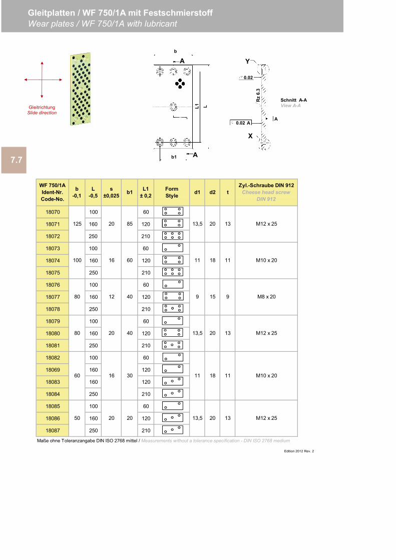
18070 100 60
18071 160 120
18072 250 210
18073 100 60
18074 160 120
18075 250 210
18076 100 60
18077 160 120
18078 250 210
18079 100 60
18080 160 120
18081 250 210
18082 100 60
18069 160 120
18083 160 120
18084 250 210
18085 100 60
18086 160 120
18087 250 210
Edition 2012 Rev. 2
M12 x 25
M10 x 20
M8 x 20
M12 x 25
M12 x 25
M10 x 20
Maße ohne Toleranzangabe DIN ISO 2768 mittel / Measurements without a tolerance specification - DIN ISO 2768 medium
13,5 20
16 30
13
11 18 11
WF 750/1AIdent-Nr.Code-No.
b-0,1
L-0,5
s±0,025 b1 t
13125
100
L1± 0,2 d2
Gleitplatten / WF 750/1A mit FestschmierstoffWear plates / WF 750/1A with lubricant
50
60
20 85
16 60
12 40
20 40
20 20
80
7.7
Zyl.-Schraube DIN 912Cheese head screw
DIN 912
80 13,5 20 13
9 15 9
11 18 11
13,5 20
FormStyle d1
X
Y
AA
0.02
0.02
Rz
6.3
b1 A
A
L1 L
b
Schnitt A-AView A-AGleitrichtung
Slide direction
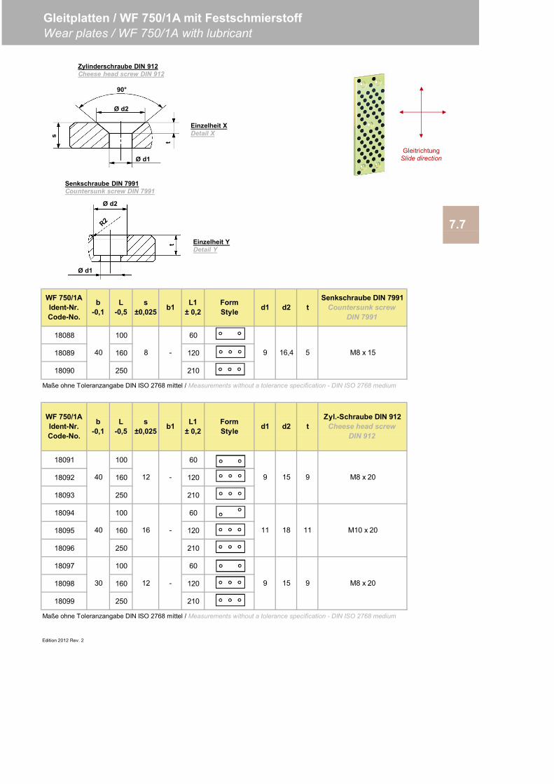
18088 100 60
18089 160 120
18090 250 210
Maße ohne Toleranzangabe DIN ISO 2768 mittel / Measurements without a tolerance specification - DIN ISO 2768 medium
18091 100 60
18092 160 120
18093 250 210
18094 100 60
18095 160 120
18096 250 210
18097 100 60
18098 160 120
18099 250 210
Maße ohne Toleranzangabe DIN ISO 2768 mittel / Measurements without a tolerance specification - DIN ISO 2768 medium
Edition 2012 Rev. 2
- 15 9
40
40
30
12
16
12
-
-
9
11
9
M8 x 20
M10 x 20
M8 x 20
915
18 11
L1± 0,2
FormStyle d1 d2 t
WF 750/1AIdent-Nr.Code-No.
b-0,1
L-0,5
s±0,025 b1
WF 750/1AIdent-Nr.Code-No.
b-0,1
L-0,5
s±0,025 b1
- 9 16,4 5
Senkschraube DIN 7991Countersunk screw
DIN 7991
L1± 0,2
FormStyle d1 d2 t
Gleitplatten / WF 750/1A mit FestschmierstoffWear plates / WF 750/1A with lubricant
7.7
Zyl.-Schraube DIN 912Cheese head screw
DIN 912
M8 x 1540 8
Ø d1
Ø d2
t
90°
Ø d1
Ø d2
t
s
Zylinderschraube DIN 912Cheese head screw DIN 912
Senkschraube DIN 7991Countersunk screw DIN 7991
GleitrichtungSlide direction
Einzelheit XDetail X
Einzelheit YDetail Y

Edition 2012 Rev. 0
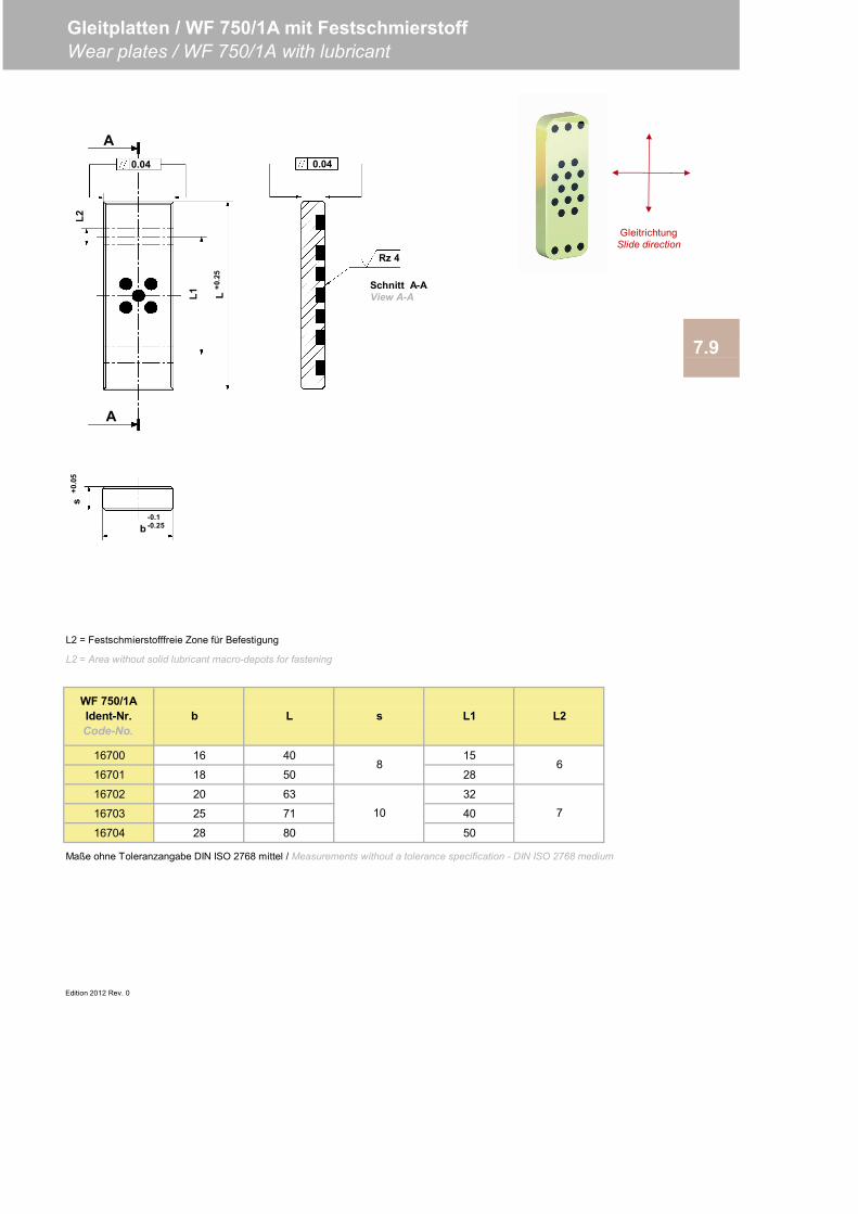
L2 = Festschmierstofffreie Zone für Befestigung
L2 = Area without solid lubricant macro-depots for fastening
16700 16 40 15
16701 18 50 28
16702 20 63 32
16703 25 71 40
16704 28 80 50
Edition 2012 Rev. 0
10 7
8 6
Maße ohne Toleranzangabe DIN ISO 2768 mittel / Measurements without a tolerance specification - DIN ISO 2768 medium
WF 750/1AIdent-Nr.Code-No.
b L s L2L1
7.9
Gleitplatten / WF 750/1A mit FestschmierstoffWear plates / WF 750/1A with lubricant
A
L2
L+0
.25
0.04
A
L1
b-0.1-0.25
0.04
Rz 4
s+0
.05
Schnitt A-AView A-A
GleitrichtungSlide direction
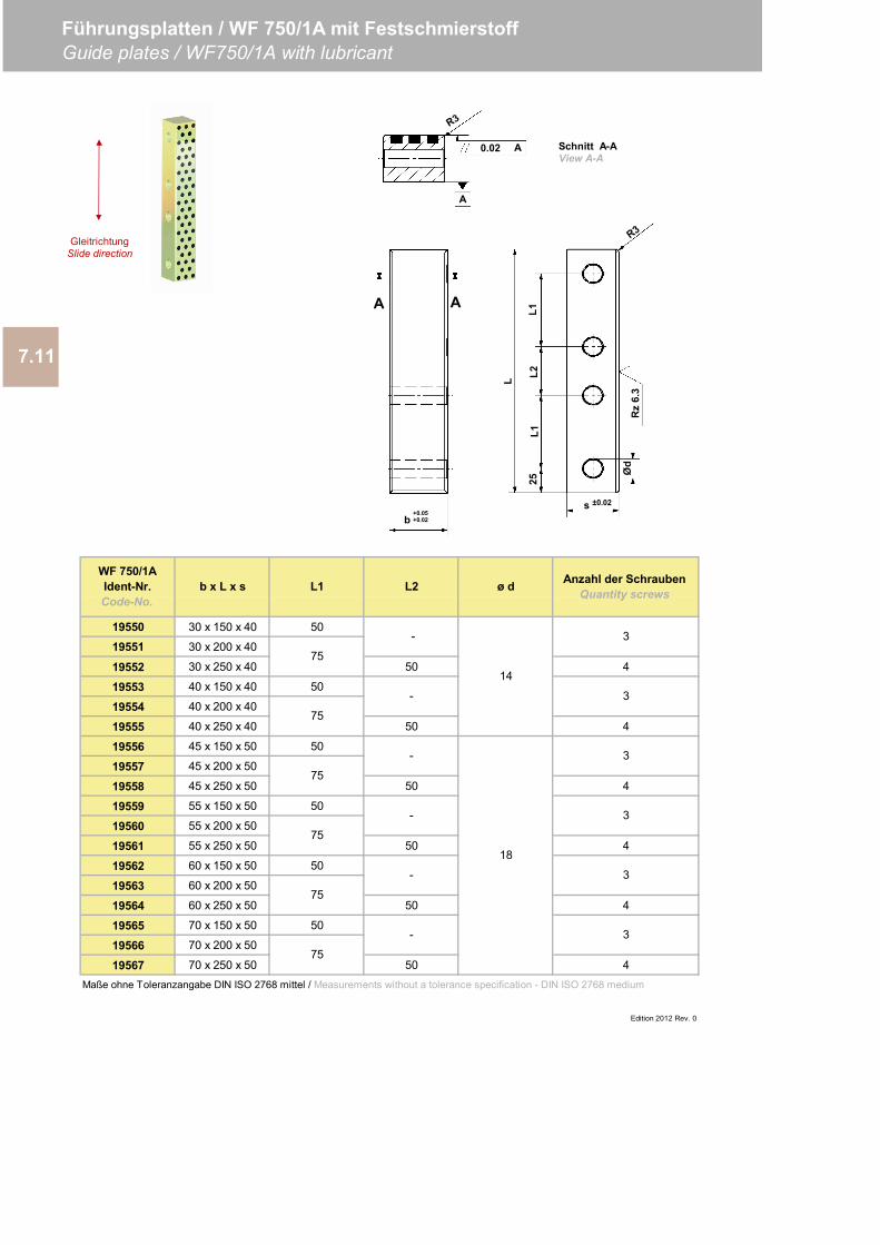
19550 30 x 150 x 40 50
19551 30 x 200 x 40
19552 30 x 250 x 40 50 4
19553 40 x 150 x 40 50
19554 40 x 200 x 40
19555 40 x 250 x 40 50 4
19556 45 x 150 x 50 50
19557 45 x 200 x 50
19558 45 x 250 x 50 50 4
19559 55 x 150 x 50 50
19560 55 x 200 x 50
19561 55 x 250 x 50 50 4
19562 60 x 150 x 50 50
19563 60 x 200 x 50
19564 60 x 250 x 50 50 4
19565 70 x 150 x 50 50
19566 70 x 200 x 50
19567 70 x 250 x 50 50 4
Edition 2012 Rev. 0
WF 750/1AIdent-Nr.Code-No.
b x L x s L1 L2
Maße ohne Toleranzangabe DIN ISO 2768 mittel / Measurements without a tolerance specification - DIN ISO 2768 medium
3
3
3
-
-
-
7.11
Führungsplatten / WF 750/1A mit FestschmierstoffGuide plates / WF750/1A with lubricant
-
ø d Anzahl der SchraubenQuantity screws
75
75
75
3
3
3
14
18
75
75
75
-
-
b+0.05+0.02
AA
0.02 A
A
Schnitt A-AView A-A
GleitrichtungSlide direction
Rz
6.3
L
L1L2
L1
Ød
s ±0.02
25
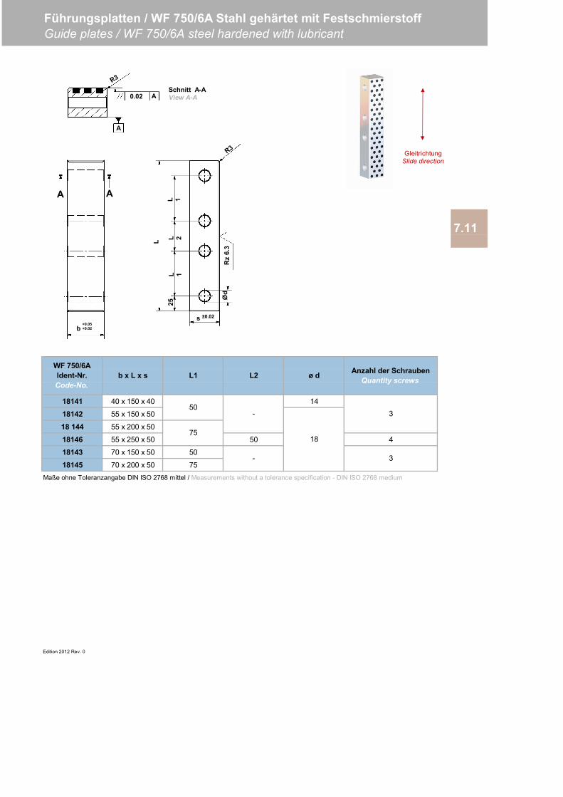
18141 40 x 150 x 40 14
18142 55 x 150 x 50
18 144 55 x 200 x 50
18146 55 x 250 x 50 50 4
18143 70 x 150 x 50 50
18145 70 x 200 x 50 75
Edition 2012 Rev. 0
7.11
Anzahl der SchraubenQuantity screws
75
-
Führungsplatten / WF 750/6A Stahl gehärtet mit FestschmierstoffGuide plates / WF 750/6A steel hardened with lubricant
WF 750/6AIdent-Nr.Code-No.
b x L x s L1 L2 ø d
-
18
3
3
Maße ohne Toleranzangabe DIN ISO 2768 mittel / Measurements without a tolerance specification - DIN ISO 2768 medium
50
0.02 A
A
Schnitt A-AView A-A
b+0.05+0.02
AA
GleitrichtungSlide direction
Rz
6.3
L
L 1L 2
L 1
Ød
s ±0.02
25
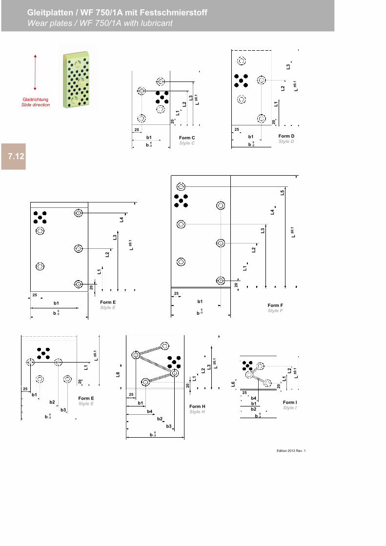
7.12
Gleitplatten / WF 750/1A mit FestschmierstoffWear plates / WF 750/1A with lubricant
Edition 2012 Rev. 1
Form CStyle C
L1L2
L3L
±0.1
20
b1
25
b 0-2
Form DStyle D
Form FStyle F
L2
L3
L±0
.1
20
L1
L4
L5
25
b1
b0
-2
Form EStyle E
L2L3
L1
L4
L±0
.1
20
25
b1
b 0-2
20L1
L±0
.1
25b1
b 0-2
b2b3
Form HStyle H
L±0
.1
20
L1
L2L3
25
b1
b 0-2
b4b2
b3
L6
Form IStyle I
20L1
L2L
±0.1
25b4
b 0-2
L6
b1b2
Form EStyle E
20L1
L2L3
L±0
.1
25
b1b 0
-2
Form DStyle D
GleitrichtungSlide direction
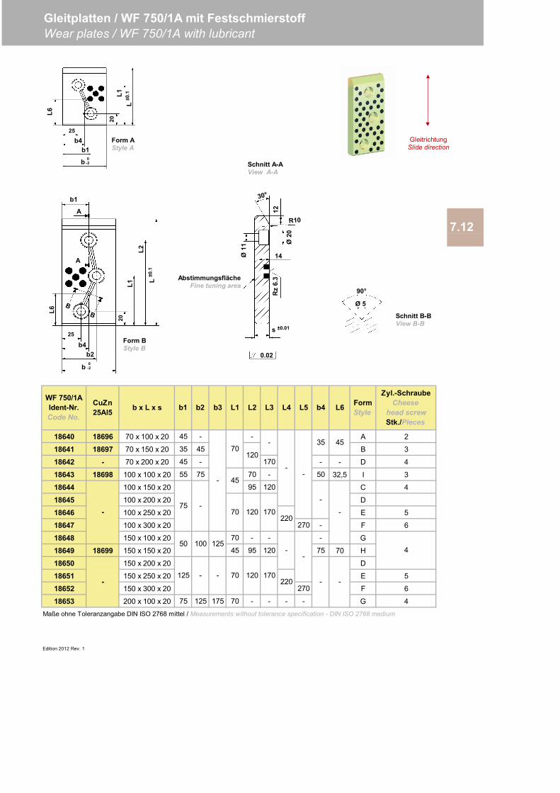
18640 18696 70 x 100 x 20 45 - - A 2
18641 18697 70 x 150 x 20 35 45 B 3
18642 - 70 x 200 x 20 45 - 170 - - D 4
18643 18698 100 x 100 x 20 55 75 70 - 50 32,5 I 3
18644 100 x 150 x 20 95 120 C 4
18645 100 x 200 x 20 D
18646 100 x 250 x 20 E 5
18647 100 x 300 x 20 270 - F 6
18648 150 x 100 x 20 70 - - - G
18649 18699 150 x 150 x 20 45 95 120 75 70 H
18650 150 x 200 x 20 D
18651 150 x 250 x 20 E 5
18652 150 x 300 x 20 270 F 6
18653 200 x 100 x 20 75 125 175 70 - - - - G 4
Edition 2012 Rev. 1
70 120
120
-
-
-
-
75 -
- 45
70
70
Gleitplatten / WF 750/1A mit FestschmierstoffWear plates / WF 750/1A with lubricant
L6
45
L2
Maße ohne Toleranzangabe DIN ISO 2768 mittel / Measurements without tolerance specification - DIN ISO 2768 medium
L5 b4
-
-
-
FormStyleb x L x s
Zyl.-SchraubeCheese
head screwStk./Pieces
35
4
170220
7.12
WF 750/1AIdent-Nr.Code No.
CuZn25Al5 b1 b2 b3 L3 L4
-
-
-
-
120 170220
L1
50 100 125
125 - -
0.02
Rz
6.3
14
Ø20
Ø11
12Abstimmungsfläche
Fine tuning area
s ±0.01
L±0
.1
20L1
L2
A
b2
L6
25
b4
b 0-2
b1
A
Form BStyle B
Form AStyle A
25
b1
b 0-2
b4
L120
L±0
.1
L6
90°
Ø 5
Schnitt B-BView B-B
GleitrichtungSlide direction
Schnitt A-AView A-A
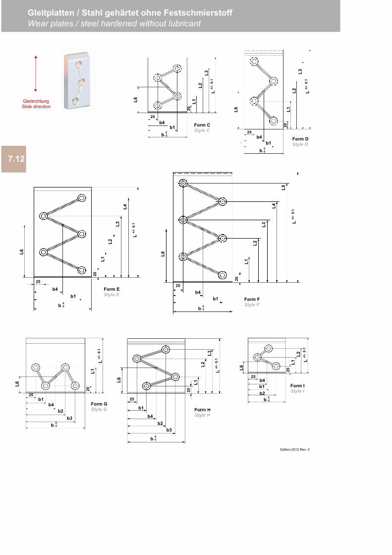
7.12
Gleitplatten / Stahl gehärtet ohne FestschmierstoffWear plates / steel hardened without lubricant
Edition 2012 Rev. 0
Form CStyle C
L1L2
L3L
+/-
0.1
20
b1
25b4
b 0-2
L6Form DStyle D
20L1
L2L3
L+/
-0.
1
25b4
b1b 0
-2
L6
Form FStyle F
L2
L3
L+/
-0.
1
20
L1
L4
L525
b4b1
b 0-2
L6
Form EStyle E
L2L3
L1
L4
L+/
-0.
1
20
25
b4b1
b 0-2
L6
Form GStyle G
20L1
L+/
-0.
1
25b1
b 0-2
b4b2
b3
L6
Form HStyle H
L+/
-0.
1
20
L1L2
L3
25
b1
b 0-2
b4b2
b3
L6
Form IStyle I
20L1
L2L
+/-
0.1
25b4
b 0-2
L6
b1b2
GleitrichtungSlide direction
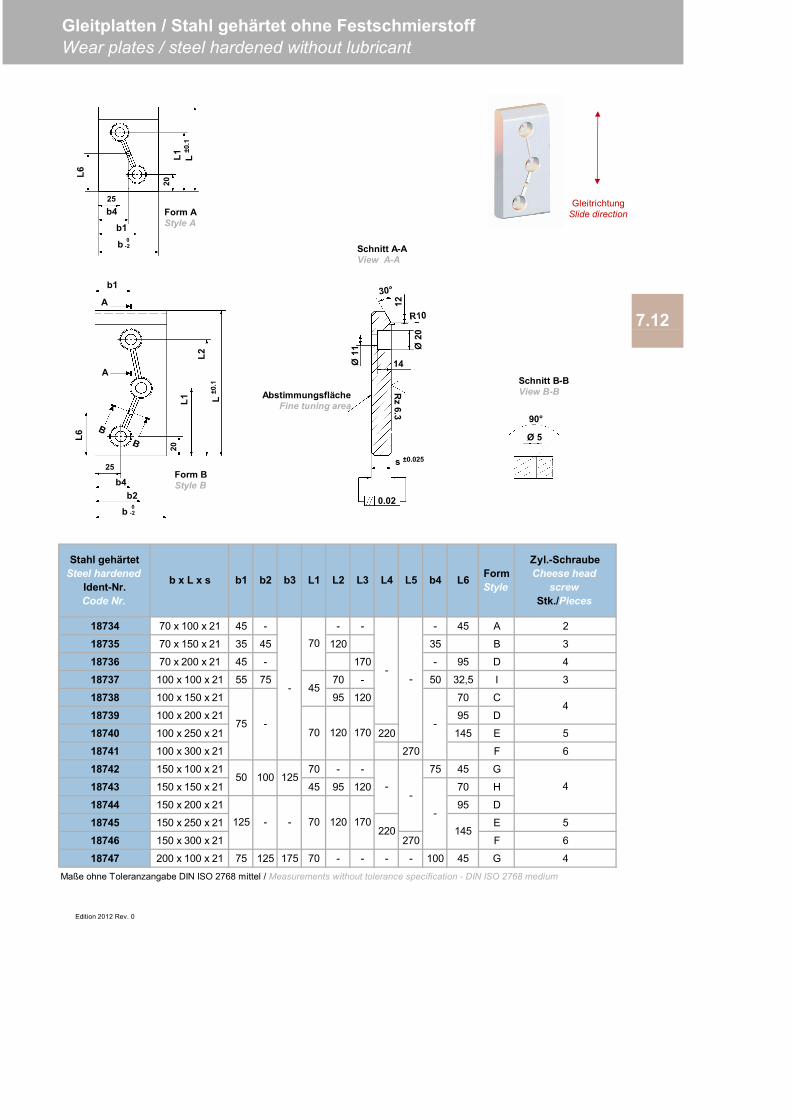
18734 70 x 100 x 21 45 - - - - 45 A 2
18735 70 x 150 x 21 35 45 120 35 B 3
18736 70 x 200 x 21 45 - 170 - 95 D 4
18737 100 x 100 x 21 55 75 70 - 50 32,5 I 3
18738 100 x 150 x 21 95 120 70 C
18739 100 x 200 x 21 95 D
18740 100 x 250 x 21 220 145 E 5
18741 100 x 300 x 21 270 F 6
18742 150 x 100 x 21 70 - - 75 45 G
18743 150 x 150 x 21 45 95 120 70 H
18744 150 x 200 x 21 95 D
18745 150 x 250 x 21 E 5
18746 150 x 300 x 21 270 F 6
18747 200 x 100 x 21 75 125 175 70 - - - - 100 45 G 4
Edition 2012 Rev. 0
4
4
145220170
-
-
50 100 125-
-
--125 12070
75 -
-
L4 L5
--
70
45
70 120 170
Stahl gehärtetSteel hardened
Ident-Nr.Code Nr.
b x L x s b1 b2 b3 b4 L6 FormStyle
Zyl.-SchraubeCheese head
screwStk./Pieces
Gleitplatten / Stahl gehärtet ohne FestschmierstoffWear plates / steel hardened without lubricant
Maße ohne Toleranzangabe DIN ISO 2768 mittel / Measurements without tolerance specification - DIN ISO 2768 medium
7.12
L1 L2 L3
0.02
Rz
6.3
14
Ø20
Ø11
12Abstimmungsfläche
Fine tuning area
s ±0.025
L±0
.1
20L1
L2
A
b2
L6
25
b4
b 0-2
b1
A
Form BStyle B
25
b1
b 0-2
b4
L120
L±0
.1
L6
Form AStyle A
90°
Ø 5
Schnitt B-BView B-B
Schnitt A-AView A-A
GleitrichtungSlide direction

Edition 2012 Rev. 0
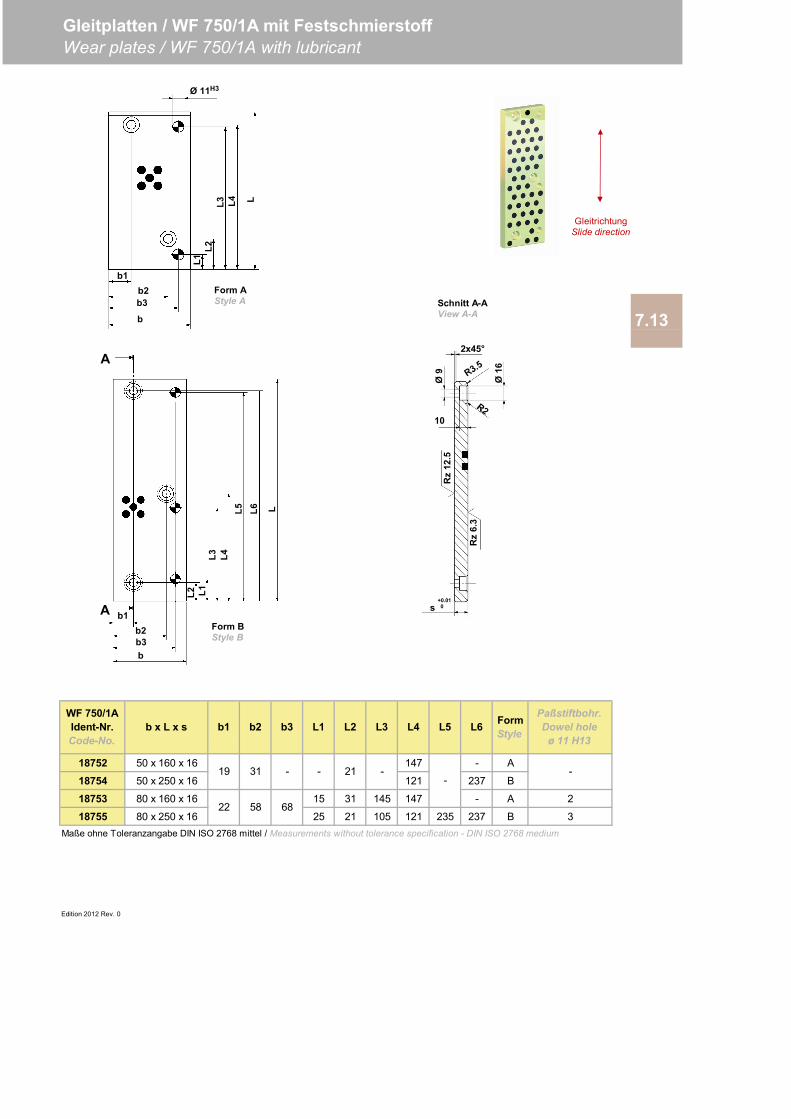
18752 50 x 160 x 16 147 - A
18754 50 x 250 x 16 121 237 B
18753 80 x 160 x 16 15 31 145 147 - A 2
18755 80 x 250 x 16 25 21 105 121 235 237 B 3Maße ohne Toleranzangabe DIN ISO 2768 mittel / Measurements without tolerance specification - DIN ISO 2768 medium
Edition 2012 Rev. 0
--
- - 21 -
Paßstiftbohr.Dowel hole
ø 11 H13L5 L6 Form
Style
WF 750/1AIdent-Nr.Code-No.
b x L x s b1
Gleitplatten / WF 750/1A mit FestschmierstoffWear plates / WF 750/1A with lubricant
L2 L3 L4
22 58 68
7.13
b2 b3 L1
19 31
L2
A b1
A
b2b3b
L1L3 L4
L5 L6 L
Rz
6.3
Ø9
s+0.010
Rz
12.5
2x45°
Ø16
10
b1b2b3
b
L1L2
L3 L4 L
Ø 11H3
Schnitt A-AView A-A
Form BStyle B
Form AStyle A
GleitrichtungSlide direction
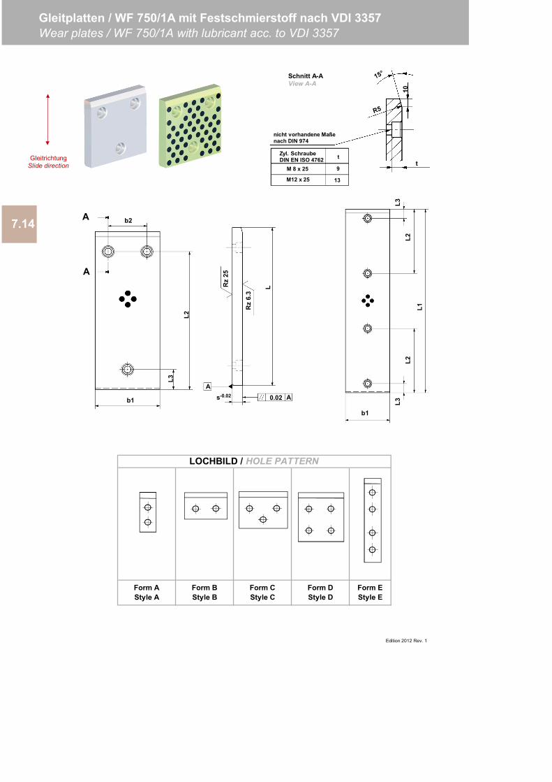
LOCHBILD / HOLE PATTERN
Form EStyle E
7.14
Edition 2012 Rev. 1
Gleitplatten / WF 750/1A mit Festschmierstoff nach VDI 3357Wear plates / WF 750/1A with lubricant acc. to VDI 3357
Form AStyle A
Form BStyle B
Form CStyle C
Form DStyle D
L
Rz
6.3
Rz
25
0.02A
s-0.02 A
nicht vorhandene Maßenach DIN 974
t
10
M12 x 25
9
13
Zyl. SchraubeDIN EN ISO 4762 t
M 8 x 25
GleitrichtungSlide direction
b1
L3
L2
b2A
A
Schnitt A-AView A-A
b1
L3L2
L3L2
L1
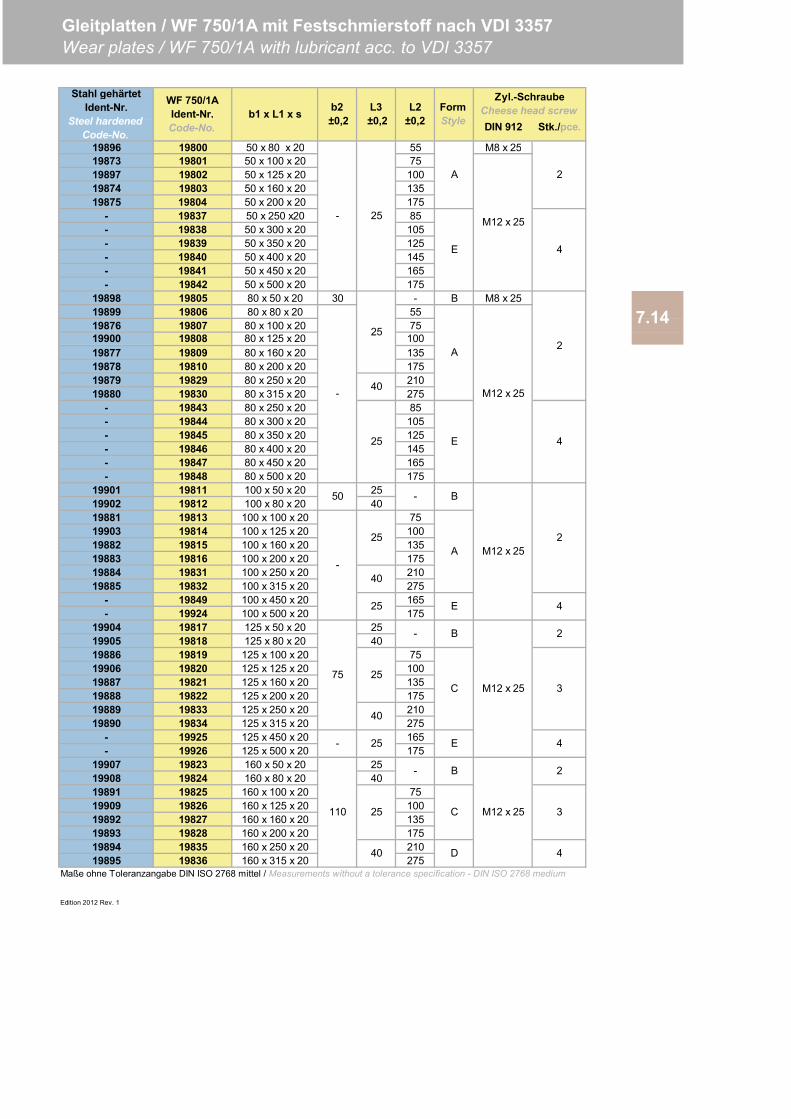
DIN 912 Stk./pce.
19896 19800 50 x 80 x 20 55 M8 x 2519873 19801 50 x 100 x 20 7519897 19802 50 x 125 x 20 10019874 19803 50 x 160 x 20 13519875 19804 50 x 200 x 20 175
- 19837 50 x 250 x20 85- 19838 50 x 300 x 20 105- 19839 50 x 350 x 20 125- 19840 50 x 400 x 20 145- 19841 50 x 450 x 20 165- 19842 50 x 500 x 20 175
19898 19805 80 x 50 x 20 30 - B M8 x 2519899 19806 80 x 80 x 20 5519876 19807 80 x 100 x 20 75
19877 19809 80 x 160 x 20 13519878 19810 80 x 200 x 20 17519879 19829 80 x 250 x 20 21019880 19830 80 x 315 x 20 275
- 19843 80 x 250 x 20 85- 19844 80 x 300 x 20 105- 19845 80 x 350 x 20 125- 19846 80 x 400 x 20 145- 19847 80 x 450 x 20 165- 19848 80 x 500 x 20 175
19901 19811 100 x 50 x 20 2519902 19812 100 x 80 x 20 4019881 19813 100 x 100 x 20 7519903 19814 100 x 125 x 20 10019882 19815 100 x 160 x 20 13519883 19816 100 x 200 x 20 17519884 19831 100 x 250 x 20 21019885 19832 100 x 315 x 20 275
- 19849 100 x 450 x 20 165- 19924 100 x 500 x 20 175
19904 19817 125 x 50 x 20 2519905 19818 125 x 80 x 20 4019886 19819 125 x 100 x 20 7519906 19820 125 x 125 x 20 10019887 19821 125 x 160 x 20 13519888 19822 125 x 200 x 20 17519889 19833 125 x 250 x 20 21019890 19834 125 x 315 x 20 275
- 19925 125 x 450 x 20 165- 19926 125 x 500 x 20 175
19907 19823 160 x 50 x 20 2519908 19824 160 x 80 x 20 4019891 19825 160 x 100 x 20 7519909 19826 160 x 125 x 20 10019892 19827 160 x 160 x 20 13519893 19828 160 x 200 x 20 17519894 19835 160 x 250 x 20 21019895 19836 160 x 315 x 20 275
Edition 2012 Rev. 1
19900
Gleitplatten / WF 750/1A mit Festschmierstoff nach VDI 3357Wear plates / WF 750/1A with lubricant acc. to VDI 3357
Maße ohne Toleranzangabe DIN ISO 2768 mittel / Measurements without a tolerance specification - DIN ISO 2768 medium
A
WF 750/1AIdent-Nr.Code-No.
b1 x L1 x s b2 ±0,2
L3 ±0,2
L2±0,2
FormStyle
100
25
40
25
-
7.14
M12 x 25
4
2
E
19808 80 x 125 x 20
E
B
D
110 C25
40
-
B
A
E
B
C
50
M12 x 25
M12 x 25
M12 x 25
2
4
2
3
4
2
3
4
75
-
-
-
25
25
40
25
25
40
- 25
Stahl gehärtetIdent-Nr.
Steel hardenedCode-No.
-
A 2
M12 x 25
E 4
Zyl.-SchraubeCheese head screw
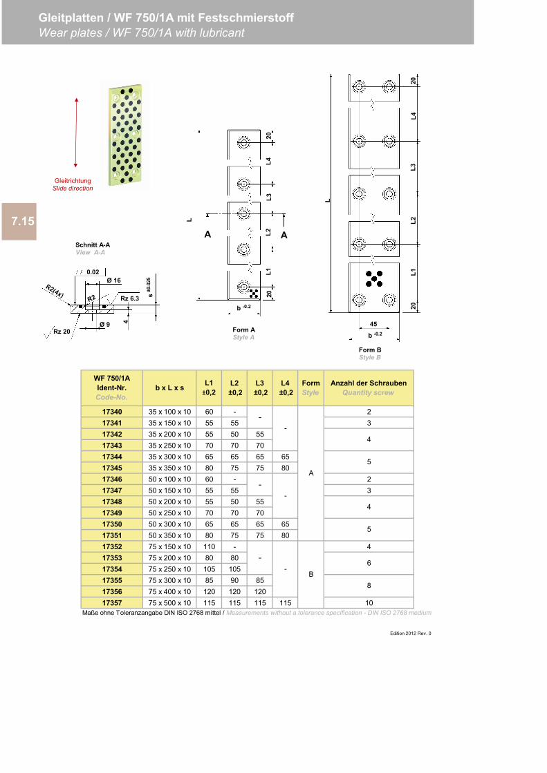
17340 35 x 100 x 10 60 - 217341 35 x 150 x 10 55 55 317342 35 x 200 x 10 55 50 5517343 35 x 250 x 10 70 70 7017344 35 x 300 x 10 65 65 65 6517345 35 x 350 x 10 80 75 75 8017346 50 x 100 x 10 60 - 217347 50 x 150 x 10 55 55 317348 50 x 200 x 10 55 50 5517349 50 x 250 x 10 70 70 7017350 50 x 300 x 10 65 65 65 6517351 50 x 350 x 10 80 75 75 8017352 75 x 150 x 10 110 - 417353 75 x 200 x 10 80 8017354 75 x 250 x 10 105 10517355 75 x 300 x 10 85 90 8517356 75 x 400 x 10 120 120 12017357 75 x 500 x 10 115 115 115 115 10
Maße ohne Toleranzangabe DIN ISO 2768 mittel / Measurements without a tolerance specification - DIN ISO 2768 medium
-
Anzahl der SchraubenQuantity screw
4
5
4
5
6
FormStyle
A
B
-
-
-
L4 ±0,2
L1±0,2
L2 ±0,2
L3 ±0,2
-
-
Edition 2012 Rev. 0
8
WF 750/1AIdent-Nr.Code-No.
b x L x s
7.15
Gleitplatten / WF 750/1A mit FestschmierstoffWear plates / WF 750/1A with lubricant
GleitrichtungSlide direction
Lb -0.2
45
20L1
L2L3
L420
Ø 9
Ø 16
4
0.02
s±0
.025
Rz 6.3
Rz 20
b -0.2
20L1
L2L3
L420
L
A A
Form AStyle A
Schnitt A-AView A-A
Form BStyle B
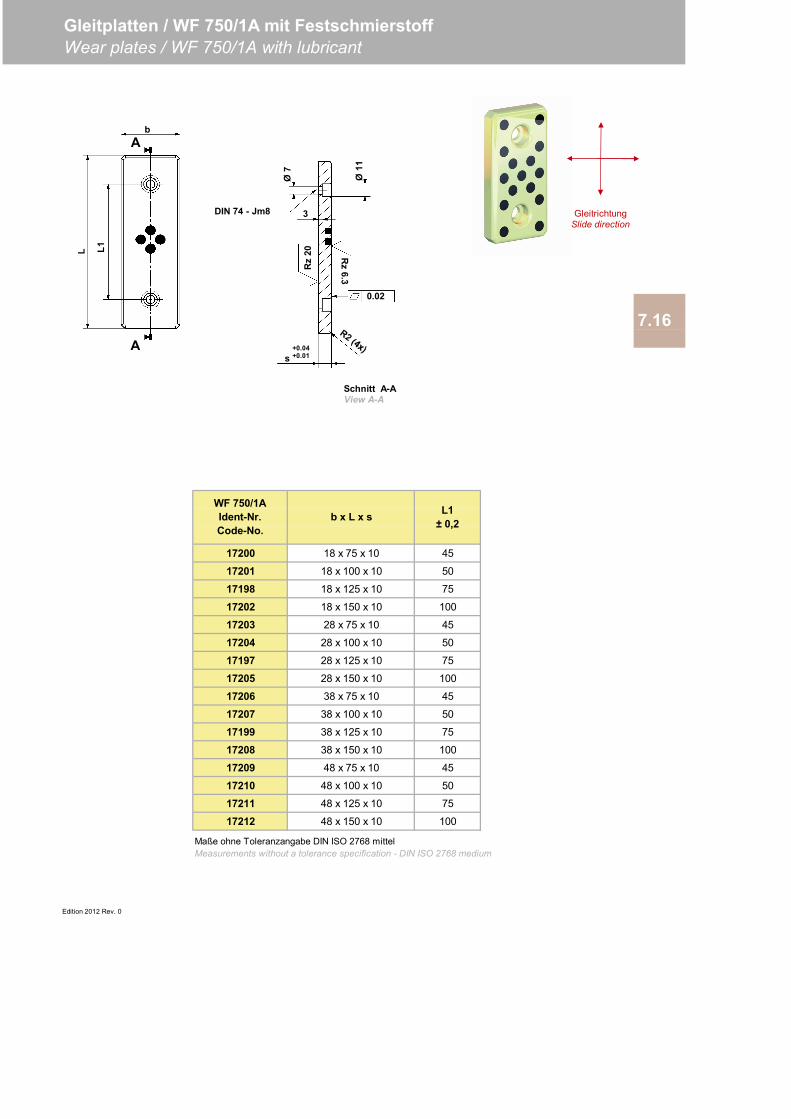
17200 18 x 75 x 10 45
17201 18 x 100 x 10 50
17198 18 x 125 x 10 75
17202 18 x 150 x 10 100
17203 28 x 75 x 10 45
17204 28 x 100 x 10 50
17197 28 x 125 x 10 75
17205 28 x 150 x 10 100
17206 38 x 75 x 10 45
17207 38 x 100 x 10 50
17199 38 x 125 x 10 75
17208 38 x 150 x 10 100
17209 48 x 75 x 10 45
17210 48 x 100 x 10 50
17211 48 x 125 x 10 75
17212 48 x 150 x 10 100
Edition 2012 Rev. 0
Gleitplatten / WF 750/1A mit FestschmierstoffWear plates / WF 750/1A with lubricant
7.16
Maße ohne Toleranzangabe DIN ISO 2768 mittelMeasurements without a tolerance specification - DIN ISO 2768 medium
WF 750/1AIdent-Nr.Code-No.
b x L x s L1± 0,2
Ø11
DIN 74 - Jm8
Ø7
3
Rz
20 Rz
6.3
0.02
s+0.04+0.01
L1L
A
A
b
GleitrichtungSlide direction
Schnitt A-AView A-A
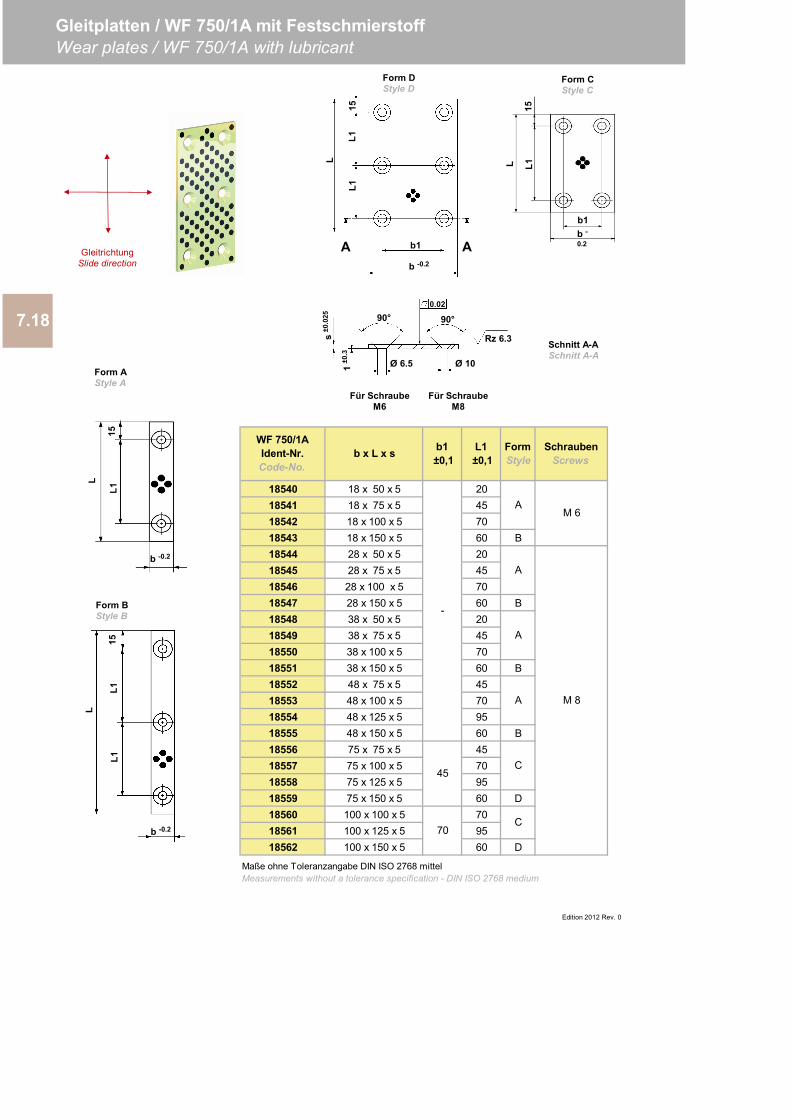
18540 18 x 50 x 5 2018541 18 x 75 x 5 4518542 18 x 100 x 5 7018543 18 x 150 x 5 60 B18544 28 x 50 x 5 2018545 28 x 75 x 5 4518546 28 x 100 x 5 7018547 28 x 150 x 5 60 B18548 38 x 50 x 5 2018549 38 x 75 x 5 4518550 38 x 100 x 5 7018551 38 x 150 x 5 60 B18552 48 x 75 x 5 4518553 48 x 100 x 5 7018554 48 x 125 x 5 9518555 48 x 150 x 5 60 B18556 75 x 75 x 5 4518557 75 x 100 x 5 7018558 75 x 125 x 5 9518559 75 x 150 x 5 60 D18560 100 x 100 x 5 7018561 100 x 125 x 5 9518562 100 x 150 x 5 60 D
7.18
Gleitplatten / WF 750/1A mit FestschmierstoffWear plates / WF 750/1A with lubricant
Edition 2012 Rev. 0
-
45
70
A
C
M 8
SchraubenScrews
WF 750/1AIdent-Nr.Code-No.
b x L x s b1 ±0,1
L1 ±0,1
Form Style
M 6
Maße ohne Toleranzangabe DIN ISO 2768 mittelMeasurements without a tolerance specification - DIN ISO 2768 medium
A
A
A
C
GleitrichtungSlide direction
b -0.2
L
L115
b -
0.2
b1
L1L
15
b -0.2
L
L115
L1
b -0.2
b1
L1
L
L115
A A
Form AStyle A
Form BStyle B
Form DStyle D
Form CStyle C
90°0.02
90°
Ø 10Ø 6.51±0
.3
s±0
.025
Rz 6.3 Schnitt A-ASchnitt A-A
Für SchraubeM6
Für SchraubeM8
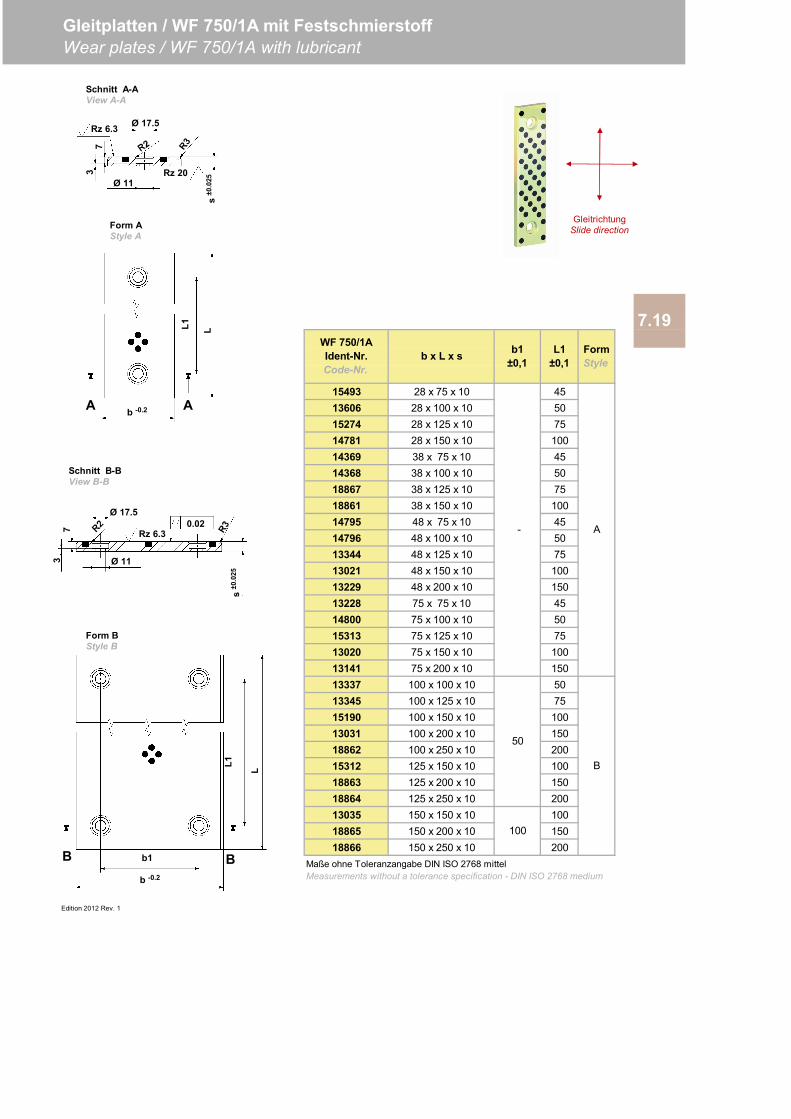
15493 28 x 75 x 10 4513606 28 x 100 x 10 5015274 28 x 125 x 10 7514781 28 x 150 x 10 10014369 38 x 75 x 10 4514368 38 x 100 x 10 5018867 38 x 125 x 10 7518861 38 x 150 x 10 10014795 48 x 75 x 10 4514796 48 x 100 x 10 5013344 48 x 125 x 10 7513021 48 x 150 x 10 10013229 48 x 200 x 10 15013228 75 x 75 x 10 4514800 75 x 100 x 10 5015313 75 x 125 x 10 7513020 75 x 150 x 10 10013141 75 x 200 x 10 15013337 100 x 100 x 10 5013345 100 x 125 x 10 7515190 100 x 150 x 10 10013031 100 x 200 x 10 15018862 100 x 250 x 10 20015312 125 x 150 x 10 10018863 125 x 200 x 10 15018864 125 x 250 x 10 20013035 150 x 150 x 10 10018865 150 x 200 x 10 15018866 150 x 250 x 10 200
Edition 2012 Rev. 1
7.19
Maße ohne Toleranzangabe DIN ISO 2768 mittelMeasurements without a tolerance specification - DIN ISO 2768 medium
-
Gleitplatten / WF 750/1A mit FestschmierstoffWear plates / WF 750/1A with lubricant
50
100
A
B
WF 750/1AIdent-Nr.Code-Nr.
b x L x s b1±0,1
L1±0,1
FormStyle
b1
b -0.2
L1
BB
0.02Rz 6.3
Ø 17.5
s±0
.025
73 Ø 11
Schnitt A-AView A-A
Form BStyle B
Schnitt B-BView B-B
Form AStyle A
b -0.2
L1
A A
L
L
Ø 17.5
s±0
.025
73
Ø 11
Rz 6.3
Rz 20
GleitrichtungSlide direction
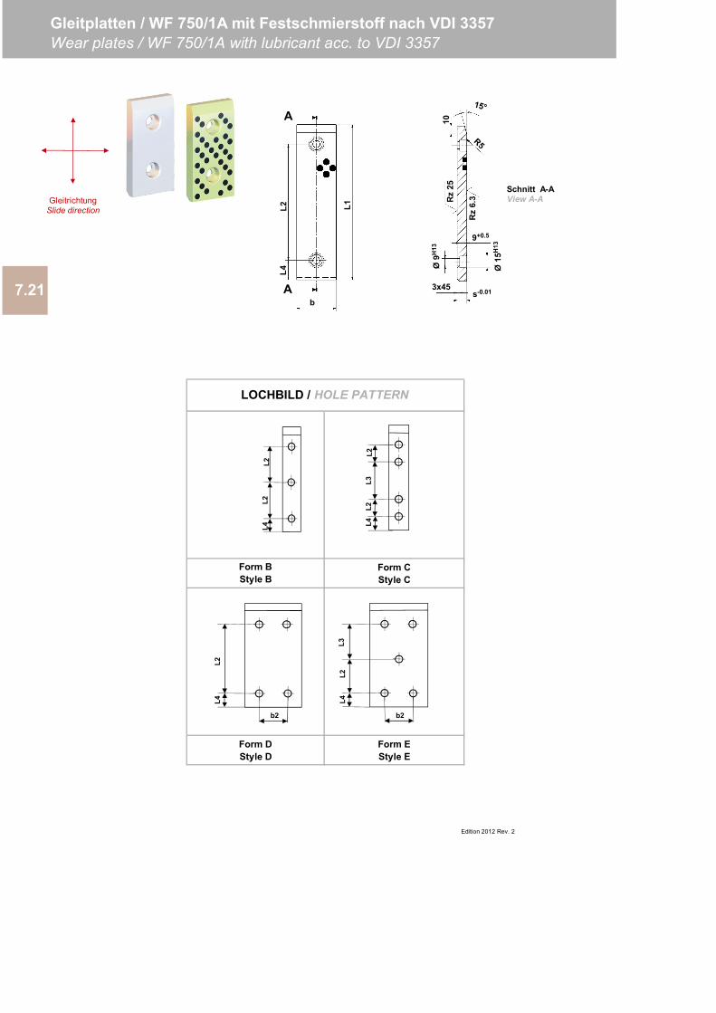
7.21
Gleitplatten / WF 750/1A mit Festschmierstoff nach VDI 3357Wear plates / WF 750/1A with lubricant acc. to VDI 3357
Edition 2012 Rev. 2
Form DStyle D
Form EStyle E
LOCHBILD / HOLE PATTERN
Form BStyle B
Form CStyle C
L4L2
L3L2
L4L2
L2
L1
L4L2
b
3x45
Rz
6.3Rz
2510
s-0.01
Ø15
H13
9+0.5
Ø9H
13
Schnitt A-AView A-A
A
A
GleitrichtungSlide direction
L4L2
b2
L4L2
L3
b2
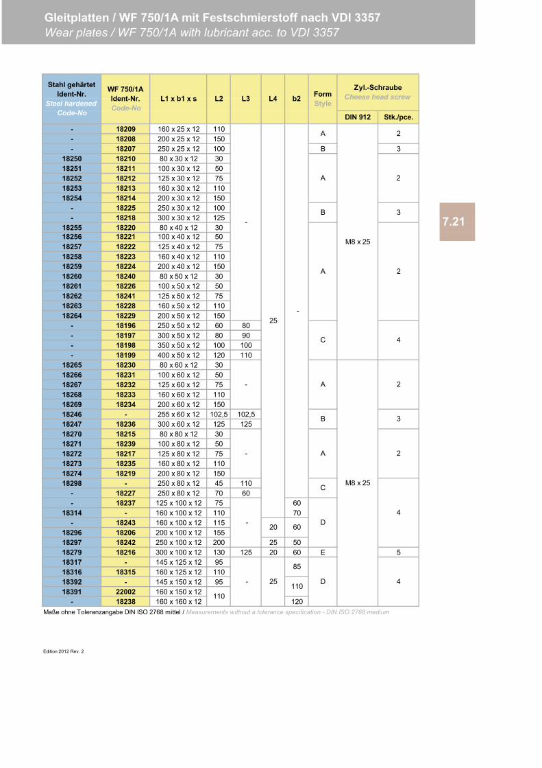
- 18209 160 x 25 x 12 110- 18208 200 x 25 x 12 150- 18207 250 x 25 x 12 100 B 3
18250 18210 80 x 30 x 12 3018251 18211 100 x 30 x 12 5018252 18212 125 x 30 x 12 7518253 18213 160 x 30 x 12 11018254 18214 200 x 30 x 12 150
- 18225 250 x 30 x 12 100- 18218 300 x 30 x 12 125
18255 18220 80 x 40 x 12 30
18257 18222 125 x 40 x 12 7518258 18223 160 x 40 x 12 11018259 18224 200 x 40 x 12 15018260 18240 80 x 50 x 12 3018261 18226 100 x 50 x 12 5018262 18241 125 x 50 x 12 7518263 18228 160 x 50 x 12 11018264 18229 200 x 50 x 12 150
- 18196 250 x 50 x 12 60 80- 18197 300 x 50 x 12 80 90- 18198 350 x 50 x 12 100 100- 18199 400 x 50 x 12 120 110
18265 18230 80 x 60 x 12 3018266 18231 100 x 60 x 12 5018267 18232 125 x 60 x 12 7518268 18233 160 x 60 x 12 11018269 18234 200 x 60 x 12 15018246 - 255 x 60 x 12 102,5 102,518247 18236 300 x 60 x 12 125 12518270 18215 80 x 80 x 12 3018271 18239 100 x 80 x 12 5018272 18217 125 x 80 x 12 7518273 18235 160 x 80 x 12 11018274 18219 200 x 80 x 12 15018298 - 250 x 80 x 12 45 110
- 18227 250 x 80 x 12 70 60- 18237 125 x 100 x 12 75 60
18314 - 160 x 100 x 12 110 70- 18243 160 x 100 x 12 115
18296 18206 200 x 100 x 12 15518297 18242 250 x 100 x 12 200 25 5018279 18216 300 x 100 x 12 130 125 20 60 E 518317 - 145 x 125 x 12 9518316 18315 160 x 125 x 12 11018392 - 145 x 150 x 12 9518391 22002 160 x 150 x 12
- 18238 160 x 160 x 12 120
Edition 2012 Rev. 2
Maße ohne Toleranzangabe DIN ISO 2768 mittel / Measurements without a tolerance specification - DIN ISO 2768 medium
Gleitplatten / WF 750/1A mit Festschmierstoff nach VDI 3357Wear plates / WF 750/1A with lubricant acc. to VDI 3357
110
L3 b2 FormStyle
Zyl.-SchraubeCheese head screw
18256
DIN 912 Stk./pce.
-
Stahl gehärtetIdent-Nr.
Steel hardened Code-No
WF 750/1AIdent-Nr.Code-No
L1 x b1 x s L2
110
18221 100 x 40 x 12 50M8 x 25
2
2
L4
3
4
2
A
A
7.21
-
D
A
A
D
M8 x 25
2
2
4
-
B 3
B
C
4
-
-
C
- 25
A
85
25
20 60

Edition 2012 Rev. 0
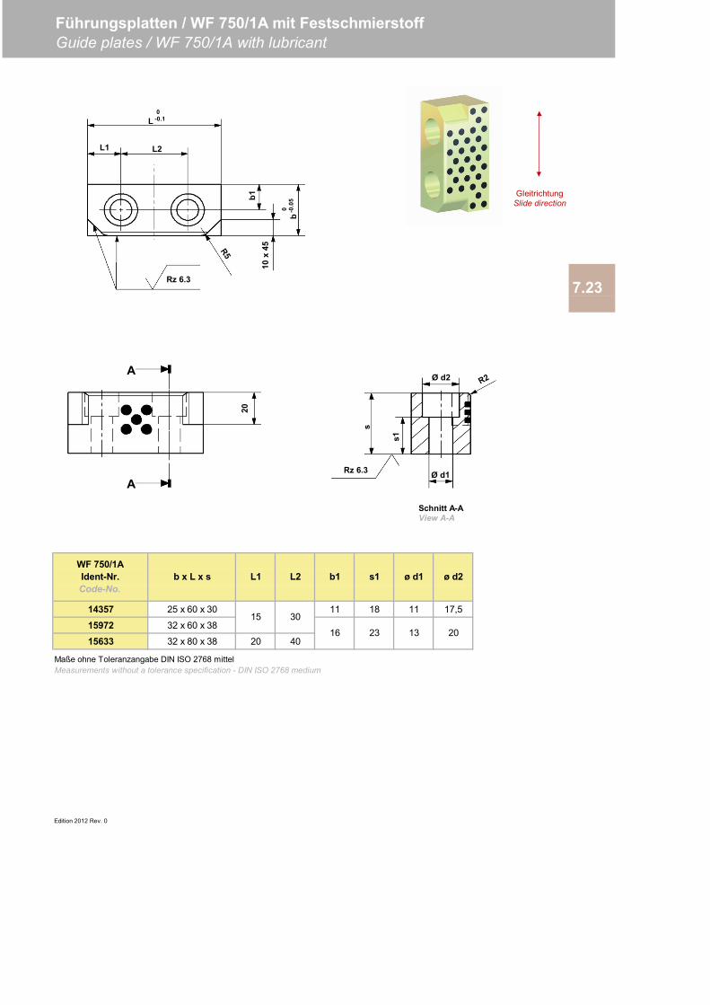
14357 25 x 60 x 30 11 18 11 17,5
15972 32 x 60 x 38
15633 32 x 80 x 38 20 40
Edition 2012 Rev. 0
Maße ohne Toleranzangabe DIN ISO 2768 mittelMeasurements without a tolerance specification - DIN ISO 2768 medium
ø d1 ø d2
15 30
16 23 13 20
WF 750/1AIdent-Nr.Code-No.
b x L x s L1 L2 b1 s1
7.23
Führungsplatten / WF 750/1A mit FestschmierstoffGuide plates / WF 750/1A with lubricant
20
A
A
Rz 6.3
L0
-0.1
L2
b0 -0
.05
10x
45b1
L1
Schnitt A-AView A-A
GleitrichtungSlide direction
Ø d2
s1
s
Ø d1Rz 6.3
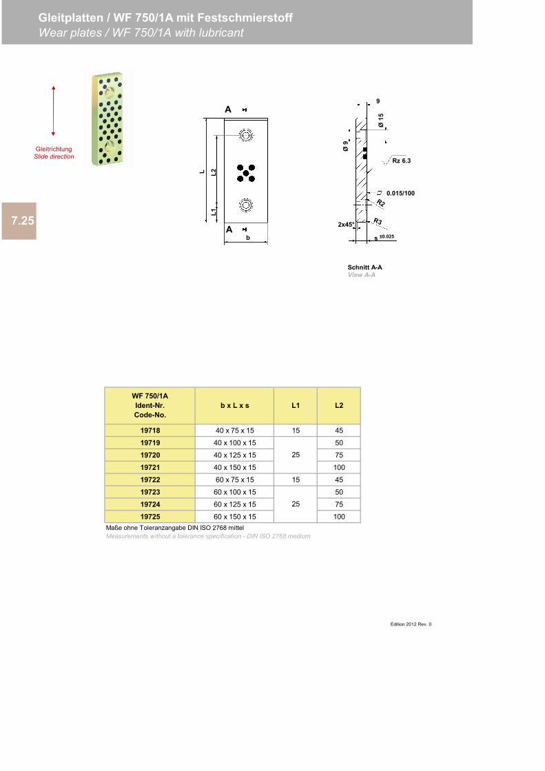
19718 40 x 75 x 15 15 45
19719 40 x 100 x 15 50
19720 40 x 125 x 15 75
19721 40 x 150 x 15 100
19722 60 x 75 x 15 15 45
19723 60 x 100 x 15 50
19724 60 x 125 x 15 75
19725 60 x 150 x 15 100Maße ohne Toleranzangabe DIN ISO 2768 mittelMeasurements without a tolerance specification - DIN ISO 2768 medium
Edition 2012 Rev. 0
WF 750/1AIdent-Nr.Code-No.
b x L x s L1
25
25
L2
7.25
Gleitplatten / WF 750/1A mit FestschmierstoffWear plates / WF 750/1A with lubricant
Rz 6.3
Ø15
9
0.015/100
Ø9
2x45°
s ±0.025A
A
b
L1L2L
Schnitt A-AView A-A
GleitrichtungSlide direction
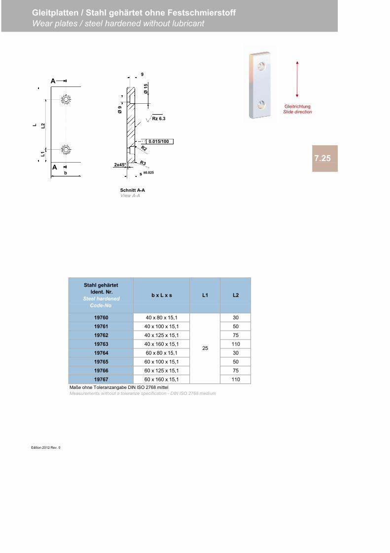
19760 40 x 80 x 15,1 30
19761 40 x 100 x 15,1 50
19762 40 x 125 x 15,1 75
19763 40 x 160 x 15,1 110
19764 60 x 80 x 15,1 30
19765 60 x 100 x 15,1 50
19766 60 x 125 x 15,1 75
19767 60 x 160 x 15,1 110
Edition 2012 Rev. 0
Maße ohne Toleranzangabe DIN ISO 2768 mittelMeasurements without a tolerance specification - DIN ISO 2768 medium
Stahl gehärtet Ident. Nr.
Steel hardenedCode-No
b x L x s L1 L2
25
7.25
Gleitplatten / Stahl gehärtet ohne FestschmierstoffWear plates / steel hardened without lubricant
Rz 6.3
Ø15
9
0.015/100
Ø9
2x45°
s ±0.025A
A
b
L1L2L
Schnitt A-AView A-A
GleitrichtungSlide direction
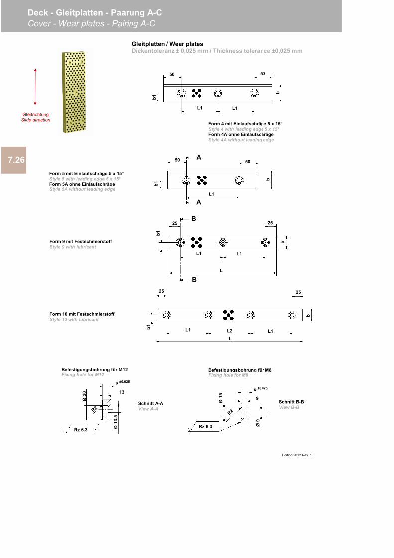
Edition 2012 Rev. 1
7.26
Deck - Gleitplatten - Paarung A-CCover - Wear plates - Pairing A-C
Form 4 mit Einlaufschräge 5 x 15°Style 4 with leading edge 5 x 15°Form 4A ohne EinlaufschrägeStyle 4A without leading edge
Form 5 mit Einlaufschräge 5 x 15°Style 5 with leading edge 5 x 15°Form 5A ohne EinlaufschrägeStyle 5A without leading edge
Form 9 mit FestschmierstoffStyle 9 with lubricant
Form 10 mit FestschmierstoffStyle 10 with lubricant
Rz 6.3 Ø13
.5
13
Ø20
s ±0.025
b
L1
50 50
L1
b1A
b1
L1
50 50
A
b
25 25
b1
b
L1 L1
L
B
B25 25
b1 L1 L1L2L
b
Schnitt A-AView A-A
Befestigungsbohrung für M12Fixing hole for M12
Schnitt B-BView B-B
9
s ±0.025
Ø9
Ø15
Rz 6.3
Befestigungsbohrung für M8Fixing hole for M8
Gleitplatten / Wear platesDickentoleranz ± 0,025 mm / Thickness tolerance ±0,025 mm
GleitrichtungSlide direction
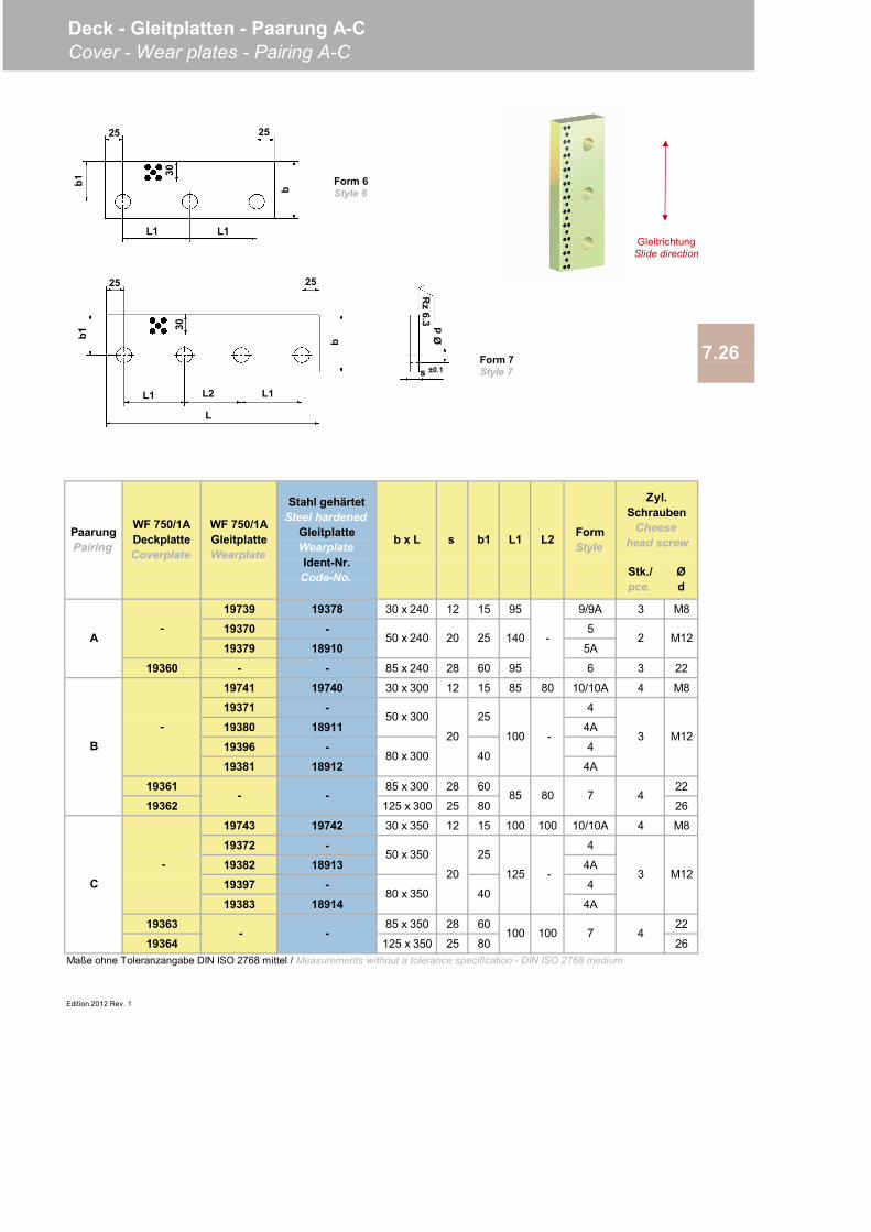
19739 19378 30 x 240 12 15 95 9/9A 3 M8
19370 - 5
19379 18910 5A
19360 - - 85 x 240 28 60 95 6 3 22
19741 19740 30 x 300 12 15 85 80 10/10A 4 M8
19371 - 4
19380 18911 4A
19396 - 4
19381 18912 4A
19361 85 x 300 28 60 22
19362 125 x 300 25 80 26
19743 19742 30 x 350 12 15 100 100 10/10A 4 M8
19372 - 4
19382 18913 4A
19397 - 4
19383 18914 4A
19363 85 x 350 28 60 22
19364 125 x 350 25 80 26
Edition 2012 Rev. 1
Maße ohne Toleranzangabe DIN ISO 2768 mittel / Measurements without a tolerance specification - DIN ISO 2768 medium
Stk./pce.
Ød
M12
M12
M12A
B
C
100 100
2
3
7 4
3
7 4
-
-100
85 80
-125
140
-
- -
50 x 240
50 x 300
80 x 300
50 x 350
80 x 350
- -
b1 L1 L2
20
20
20
25
25
40
40
25
PaarungPairing b x L s Form
Style
Zyl.Schrauben
Cheese head screw
Stahl gehärtetSteel hardened
GleitplatteWearplateIdent-Nr.Code-No.
WF 750/1AGleitplatteWearplate
WF 750/1ADeckplatteCoverplate
-
-
7.26
Deck - Gleitplatten - Paarung A-CCover - Wear plates - Pairing A-C
Rz
6.3Ø
d
s ±0.1Form 7Style 7
Form 6Style 6
b1
L1
b
2525
L1
30
25
L
b1
25
L1L1 L2
b
30
GleitrichtungSlide direction
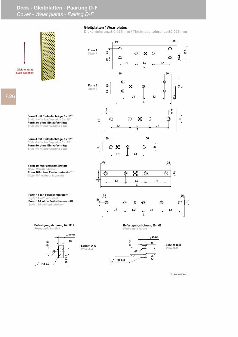
Edition 2012 Rev. 1
7.26
Deck - Gleitplatten - Paarung D-FCover - Wear plates - Pairing D-F
Form 4 mit Einlaufschräge 5 x 15°Style 4 with leading edge 5 x 15°Form 4A ohne EinlaufschrägeStyle 4A without leading edge
Form 10 mit FestschmierstoffStyle 10 with lubricantForm 10A ohne FestschmierstofffStyle 10A without lubricant
bL1
50 50
L1
b1
50
50
L1 L1L2L
b1
b
25 25
L1 L1L2 L2L
b1
b
L1 L1
L
50 50
62.5
12 57525
7525 62
.5
125
L1 L1L2L
50 50
Gleitplatten / Wear platesDickentoleranz ± 0,025 mm / Thickness tolerance ±0,025 mm
Schnitt A-AView A-A
Befestigungsbohrung für M12Fixing hole for M12
Schnitt B-BView B-B
Befestigungsbohrung für M8Fixing hole for M8
Form 11 mit FestschmierstoffStyle 11 with lubricantForm 11A ohne FestschmierstofffStyle 11A without lubricant
Form 3 mit Einlaufschräge 5 x 15°Style 3 with leading edge 5 x 15°Form 3A ohne EinlaufschrägeStyle 3A without leading edge
Form 1Style 1
Form 2Style 2
GleitrichtungSlide direction
25 25
b 1 L1 L1L2L
b
Rz 6.3 Ø13
.5
13
Ø20
s ±0.025
9
s ±0.025
Ø9
Ø15
Rz 6.3
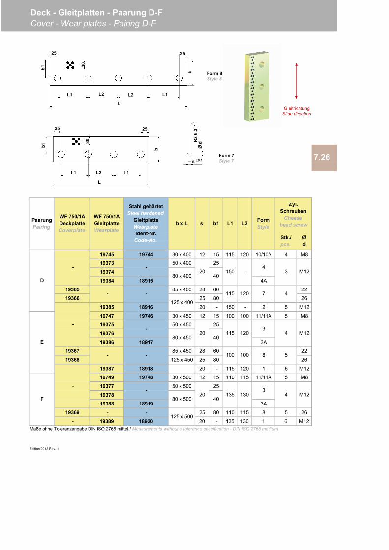
19745 19744 30 x 400 12 15 115 120 10/10A 4 M8
19373 50 x 400 25
1937419384 18915 4A
19365 85 x 400 28 60 22
19366 25 80 26
19385 18916 20 - 150 - 2 5 M12
19747 19746 30 x 450 12 15 100 100 11/11A 5 M8
19375 50 x 450 25
1937619386 18917 3A
19367 85 x 450 28 60 22
19368 125 x 450 25 80 26
19387 18918 20 - 115 120 1 6 M12
19749 19748 30 x 500 12 15 110 115 11/11A 5 M8
19377 50 x 500 25
1937819388 18919 3A
19369 - - 25 80 110 115 8 5 26
- 19389 18920 20 - 135 130 1 6 M12
Edition 2012 Rev. 1
M12130135
M12
115 120 7 4
4
4
5
40
3
3
115
20
120
8
40
-
80 x 400
125 x 400
80 x 500
80 x 450
125 x 500
Maße ohne Toleranzangabe DIN ISO 2768 mittel / Measurements without a tolerance specification - DIN ISO 2768 medium
D
E
F
-
-
-
- - 100 100
-
-
-
20
-
40150 -
43
Ød
20 M12
7.26
PaarungPairing
WF 750/1ADeckplatteCoverplate
WF 750/1AGleitplatteWearplate
Stahl gehärtetSteel hardened
GleitplatteWearplateIdent-Nr.Code-No.
b x L s b1 L1 L2 FormStyle
Zyl.Schrauben
Cheese head screw
Stk./pce.
Deck - Gleitplatten - Paarung D-FCover - Wear plates - Pairing D-F
Rz
6.3
Ød
s ±0.1
25
L
b1
25
L1L1 L2
bForm 7Style 7
25
L
b1
25
L1L1 L2
b
L2
Form 8Style 8
GleitrichtungSlide direction
3030

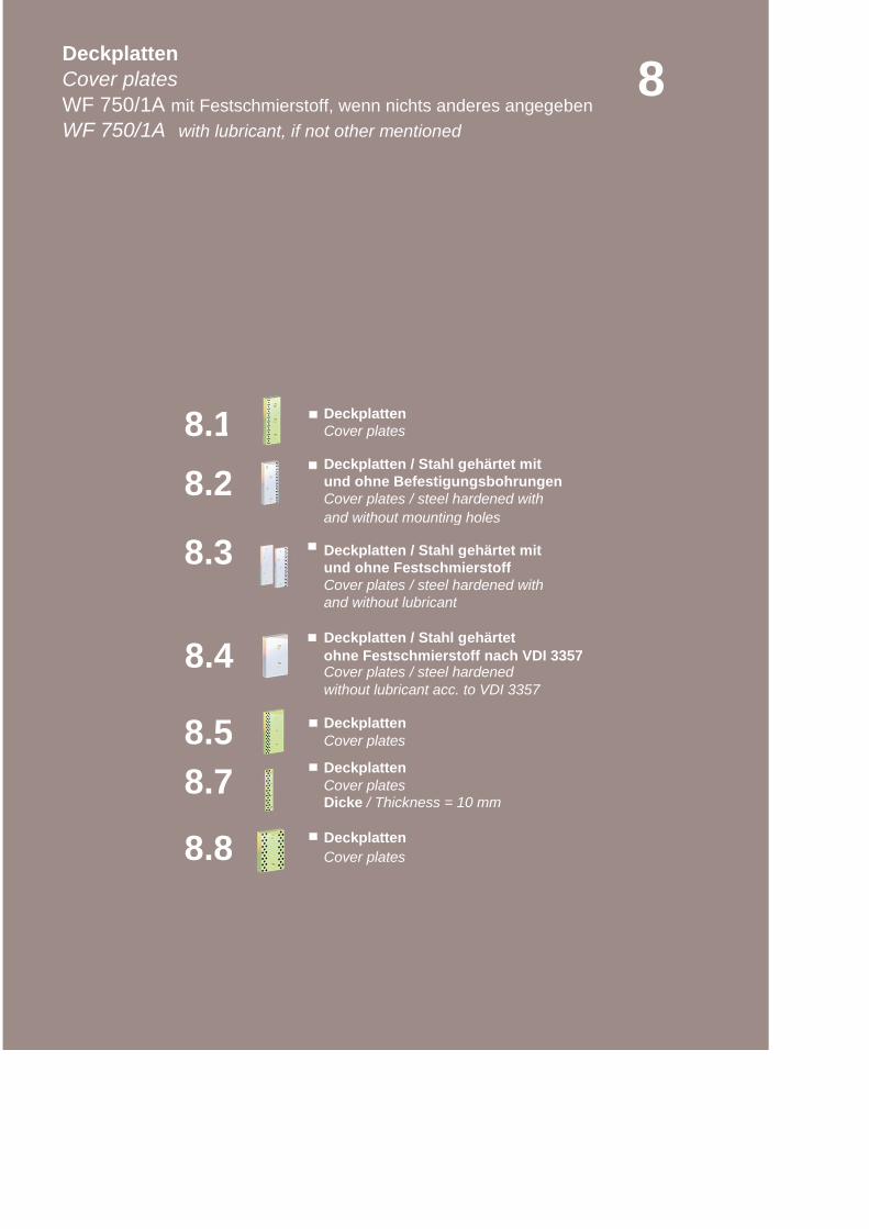
Cover plates
und ohne Befestigungsbohrungen
and without mounting holes
Deckplatten / Stahl gehärtet mit
Cover plates / steel hardened withand without lubricant
ohne Festschmierstoff nach VDI 3357
without lubricant acc. to VDI 3357
Cover plates
Cover plates
8.8
8.2
8.4
8.7
8.1
8.5
und ohne Festschmierstoff
Deckplatten / Stahl gehärtet
Cover plates / steel hardened
Deckplatten
Deckplatten
Dicke / Thickness = 10 mm
DeckplattenCover plates
8DeckplattenCover platesWF 750/1A mit Festschmierstoff, wenn nichts anderes angegebenWF 750/1A with lubricant, if not other mentioned
8.3
Deckplatten
Deckplatten / Stahl gehärtet mit
Cover plates / steel hardened with
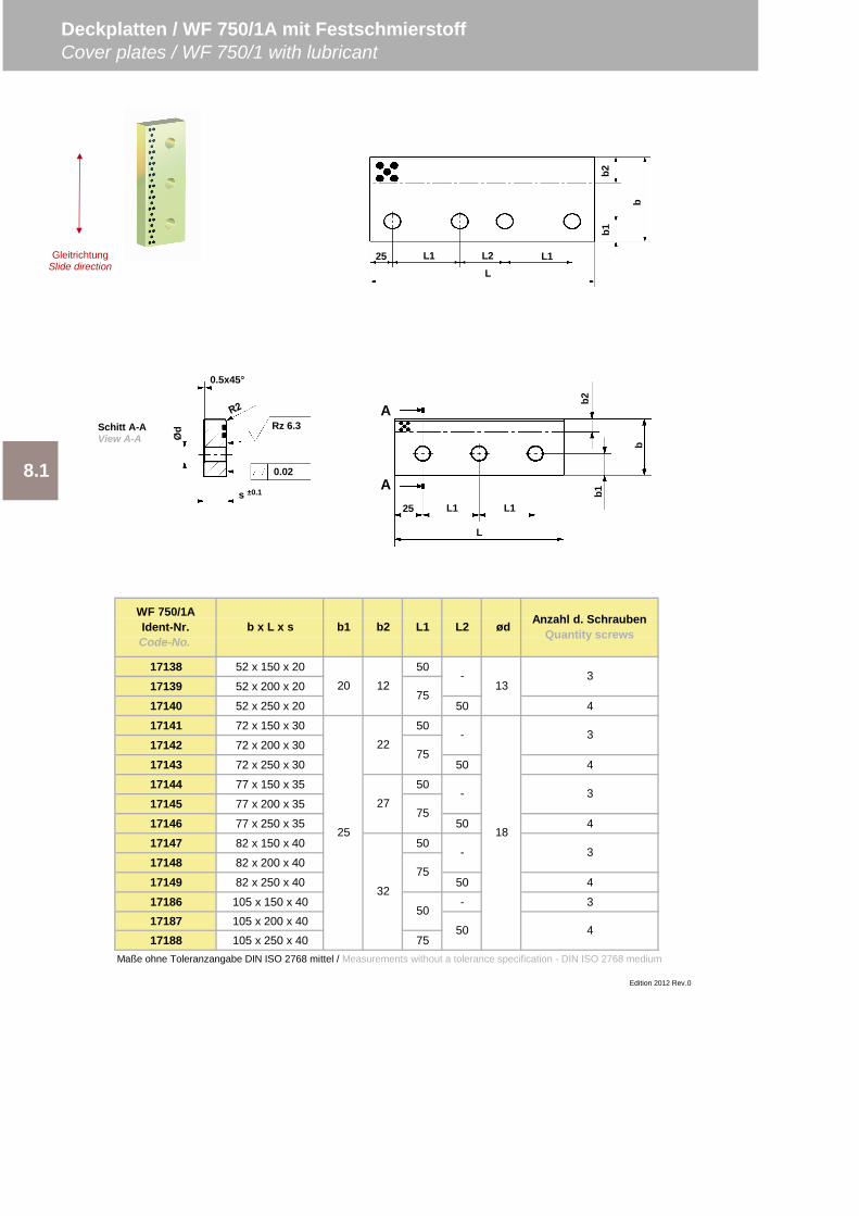
17138 52 x 150 x 20 50
17139 52 x 200 x 20
17140 52 x 250 x 20 50 4
17141 72 x 150 x 30 50
17142 72 x 200 x 30
17143 72 x 250 x 30 50 4
17144 77 x 150 x 35 50
17145 77 x 200 x 35
17146 77 x 250 x 35 50 4
17147 82 x 150 x 40 50
17148 82 x 200 x 40
17149 82 x 250 x 40 50 4
17186 105 x 150 x 40 - 317187 105 x 200 x 4017188 105 x 250 x 40 75
Maße ohne Toleranzangabe DIN ISO 2768 mittel / Measurements without a tolerance specification - DIN ISO 2768 medium
Edition 2012 Rev.0
-
-
-
-
50
13
18
3
3
3
3
4
L1 ød Anzahl d. SchraubenQuantity screws
20
25
12
22
27
32
75
75
L2
75
75
50
Deckplatten / WF 750/1A mit FestschmierstoffCover plates / WF 750/1 with lubricant
8.1
WF 750/1AIdent-Nr.Code-No.
b x L x s b1 b2
25 L1 L2 L1L
b1b2
b
25 L1 L1
L
b
b2b1
A
A0.02
Rz 6.3
0.5x45°
s ±0.1
ØdSchitt A-A
View A-A
GleitrichtungSlide direction
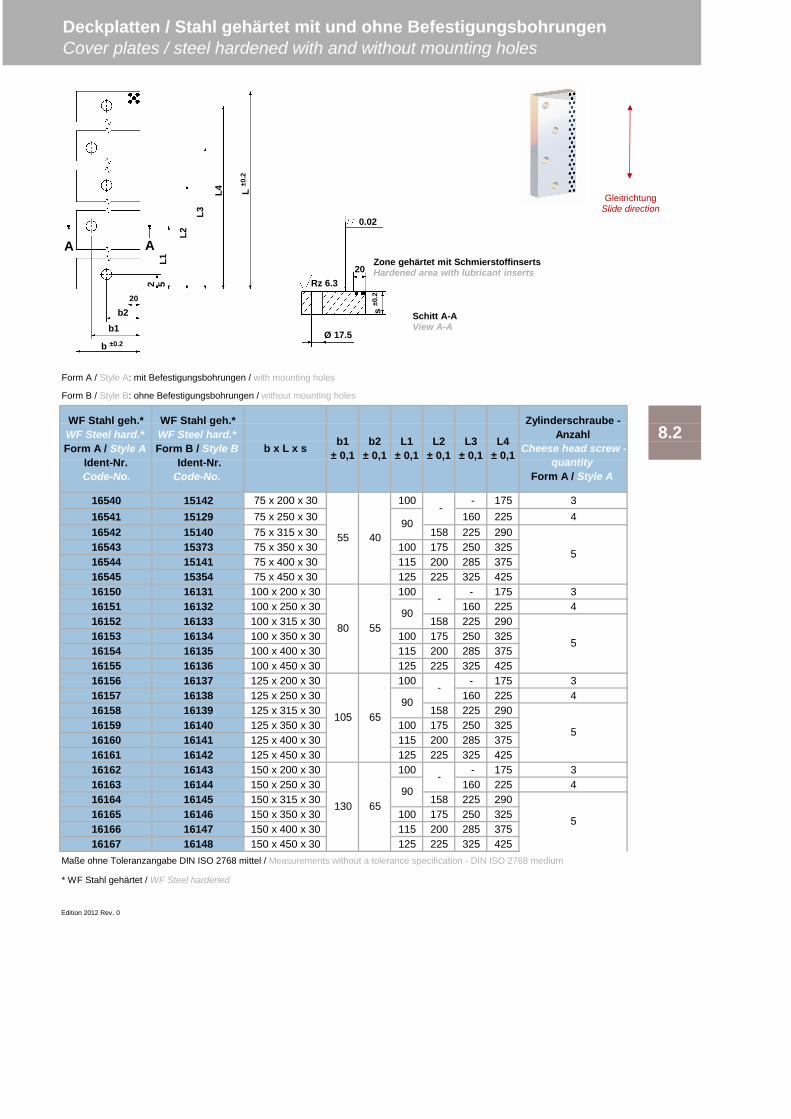
Form A / Style A: mit Befestigungsbohrungen / with mounting holes
Form B / Style B: ohne Befestigungsbohrungen / without mounting holes
16540 15142 75 x 200 x 30 100 - 175 316541 15129 75 x 250 x 30 160 225 416542 15140 75 x 315 x 30 158 225 29016543 15373 75 x 350 x 30 100 175 250 32516544 15141 75 x 400 x 30 115 200 285 37516545 15354 75 x 450 x 30 125 225 325 42516150 16131 100 x 200 x 30 100 - 175 316151 16132 100 x 250 x 30 160 225 416152 16133 100 x 315 x 30 158 225 29016153 16134 100 x 350 x 30 100 175 250 32516154 16135 100 x 400 x 30 115 200 285 37516155 16136 100 x 450 x 30 125 225 325 42516156 16137 125 x 200 x 30 100 - 175 316157 16138 125 x 250 x 30 160 225 416158 16139 125 x 315 x 30 158 225 29016159 16140 125 x 350 x 30 100 175 250 32516160 16141 125 x 400 x 30 115 200 285 37516161 16142 125 x 450 x 30 125 225 325 42516162 16143 150 x 200 x 30 100 - 175 316163 16144 150 x 250 x 30 160 225 416164 16145 150 x 315 x 30 158 225 29016165 16146 150 x 350 x 30 100 175 250 32516166 16147 150 x 400 x 30 115 200 285 37516167 16148 150 x 450 x 30 125 225 325 425
Maße ohne Toleranzangabe DIN ISO 2768 mittel / Measurements without a tolerance specification - DIN ISO 2768 medium
* WF Stahl gehärtet / WF Steel hardened
Edition 2012 Rev. 0
L1± 0,1
L2± 0,1
L3± 0,1
L4± 0,1
Zylinderschraube -Anzahl
Cheese head screw -quantity
Form A / Style A
WF Stahl geh.*WF Steel hard.*Form A / Style A
Ident-Nr. Code-No.
WF Stahl geh.*WF Steel hard.*Form B / Style B
Ident-Nr.Code-No.
b x L x s b1± 0,1
b2± 0,1
-
-90
90
55 4090
-
105 65
130 6590
-
80 55
5
5
5
5
8.2
Deckplatten / Stahl gehärtet mit und ohne BefestigungsbohrungenCover plates / steel hardened with and without mounting holes
2 5
20
L1
b2
L2
L3
L4 L±0
.2
b1
b ±0.2
A A
GleitrichtungSlide direction
Rz 6.3
0.02
20
Ø 17.5
s±0
.2
Schitt A-AView A-A
Zone gehärtet mit SchmierstoffinsertsHardened area with lubricant inserts
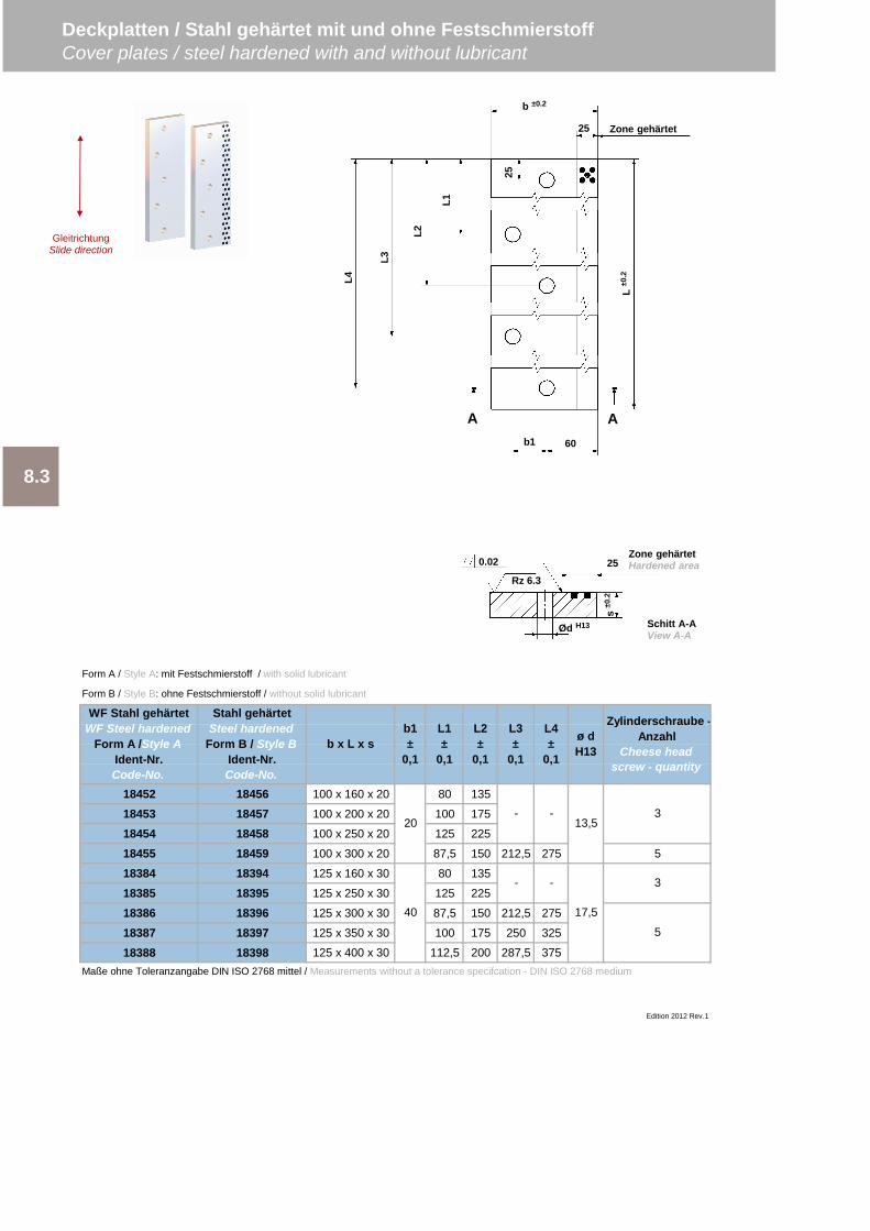
Form A / Style A: mit Festschmierstoff / with solid lubricant
Form B / Style B: ohne Festschmierstoff / without solid lubricant
18452 18456 100 x 160 x 20 80 135
18453 18457 100 x 200 x 20 100 175
18454 18458 100 x 250 x 20 125 225
18455 18459 100 x 300 x 20 87,5 150 212,5 275 5
18384 18394 125 x 160 x 30 80 135
18385 18395 125 x 250 x 30 125 225
18386 18396 125 x 300 x 30 87,5 150 212,5 275
18387 18397 125 x 350 x 30 100 175 250 325
18388 18398 125 x 400 x 30 112,5 200 287,5 375Maße ohne Toleranzangabe DIN ISO 2768 mittel / Measurements without a tolerance specifcation - DIN ISO 2768 medium
3
3
5
13,5
17,5
20
40
- -
- -
Zylinderschraube -Anzahl
Cheese headscrew - quantity
WF Stahl gehärtetWF Steel hardened
Form A /Style AIdent-Nr.Code-No.
Stahl gehärtetSteel hardened
Form B / Style BIdent-Nr.Code-No.
b x L x sb1±
0,1
L1±
0,1
Edition 2012 Rev.1
8.3
L2±
0,1
L3±
0,1
L4±
0,1
ø dH13
Deckplatten / Stahl gehärtet mit und ohne FestschmierstoffCover plates / steel hardened with and without lubricant
GleitrichtungSlide direction
25
b ±0.2
b1 60
25
L1
L2
L3
L4
L±0
.2
A A
Zone gehärtet
s±0
.2
Ød H13
Rz 6.325
Zone gehärtetHardened area0.02
Schitt A-AView A-A
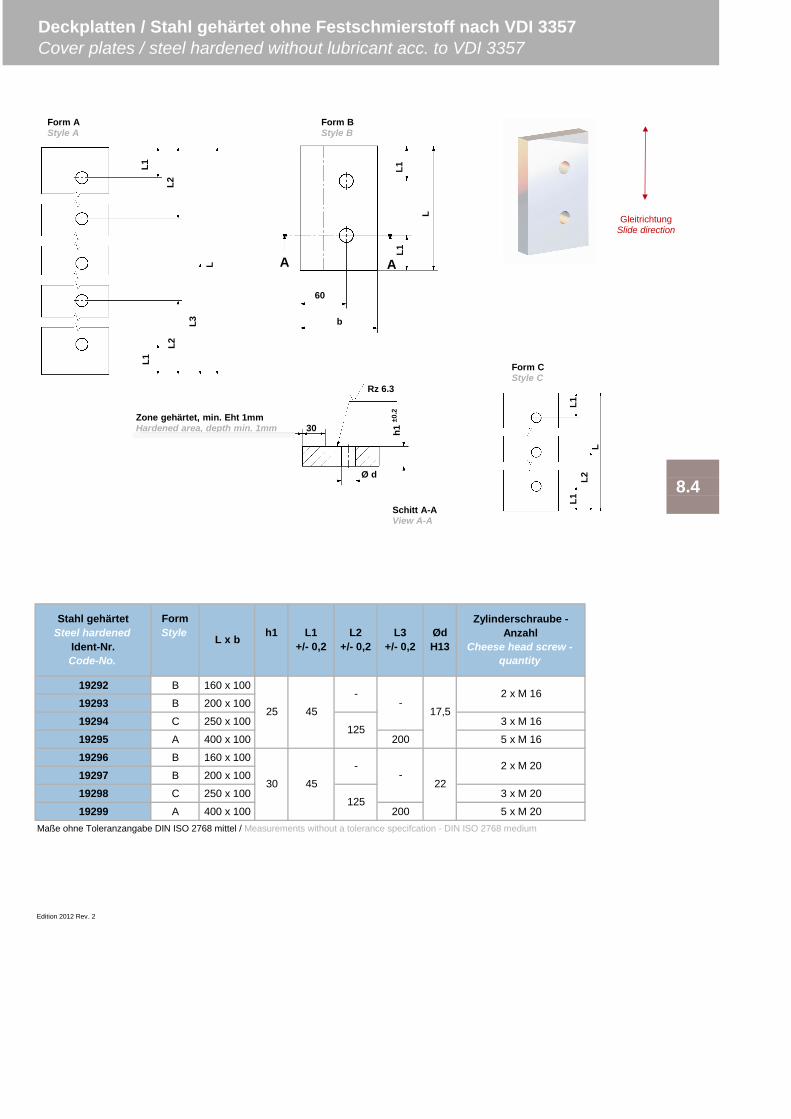
19292 B 160 x 100
19293 B 200 x 100
19294 C 250 x 100 3 x M 16
19295 A 400 x 100 200 5 x M 16
19296 B 160 x 100
19297 B 200 x 100
19298 C 250 x 100 3 x M 20
19299 A 400 x 100 200 5 x M 20Maße ohne Toleranzangabe DIN ISO 2768 mittel / Measurements without a tolerance specifcation - DIN ISO 2768 medium
Edition 2012 Rev. 2
8.4
125
-
Deckplatten / Stahl gehärtet ohne Festschmierstoff nach VDI 3357Cover plates / steel hardened without lubricant acc. to VDI 3357
Stahl gehärtetSteel hardened
Ident-Nr.Code-No.
L x b h1 L1+/- 0,2
L2+/- 0,2
FormStyle
-
30 45
45
22
Zylinderschraube -Anzahl
Cheese head screw -quantity
2 x M 16
2 x M 20
25 17,5
ØdH13
L3+/- 0,2
-
-
125
L1
L2
L1
L2
L3
L1L1
L
Ø d
h1±0
.2
30
Rz 6.3
Zone gehärtet, min. Eht 1mmHardened area, depth min. 1mm
L1
L
60
b
A A
Schitt A-AView A-A
GleitrichtungSlide direction
L
L2
L1
Form AStyle A
Form BStyle B
Form CStyle C
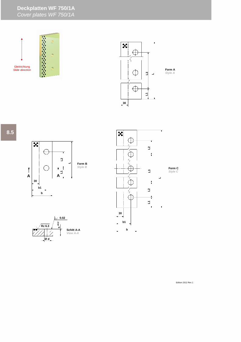
Edition 2012 Rev.1
8.5
Deckplatten WF 750/1ACover plates WF 750/1A
0.02
Ø d
s±0
.2
Rz 6.3Schitt A-AView A-A
30
L1L3 L
Form AStyle A
Form BStyle B
30
b1
b
L1L2
L3L2
L
Form CStyle C
30
b1
b
L1L2
L
A A
GleitrichtungSlide direction

19122 160 x 85 70
19123 200 x 85 110
19124 250 x 85 160
19125 300 x 85 210
19135 350 x 85 260
19136 400 x 85 80 150 5 x M 20
19356 1005 x 85 - - - - ungebohrt / without hole
19083 160 x 125 70
19084 200 x 125 110
19085 250 x 125 - 160 B 3 x M 16
19086 400 x 125 80 150 5 x M 16
19359 1005 x 125 - - - - ungebohrt / without hole
14021 160 x 125 70
14020 200 x 125 110
19087 250 x 125 160
19082 300 x 125 210
19088 350 x 125 260
14019 400 x 125 150
19089 450 x 125 190
19094 500 x 125 240
19357 1005 x 125 - - - - - ungebohrt / without holeMaße ohne Toleranzangabe DIN ISO 2768 mittel / Measurements without a tolerance specifcation - DIN ISO 2768 medium
Edition 2012 Rev. 1
B
C
2 x M 20
3 x M 20
2 x M 16
2 x M 20
3 x M 20
5 x M 20
A
B
C
A
C
A
22
18
22
80
-
-
-
-
-
7530
45
50
60 45
75 45
30
25
WF 750/1AIdent-Nr.Code-No.
Zylinderschraube -Anzahl
Cheese head screw -quantity
L x b b1 s L1 L2± 0.2
L3± 0.2 Ø d Form
Style
8.5
Deckplatten WF 750/1ACover plates WF 750/1A
GleitrichtungSlide direction
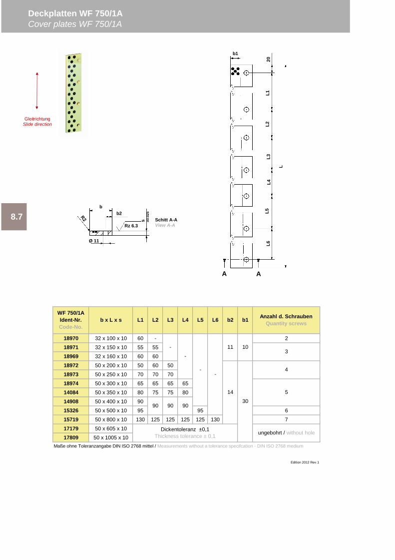
18970 32 x 100 x 10 60 - 2
18971 32 x 150 x 10 55 55
18969 32 x 160 x 10 60 60
18972 50 x 200 x 10 50 60 50
18973 50 x 250 x 10 70 70 70
18974 50 x 300 x 10 65 65 65 65
14084 50 x 350 x 10 80 75 75 80
14908 50 x 400 x 10 90
15326 50 x 500 x 10 95 95 6
15719 50 x 800 x 10 130 125 125 125 125 130 7
17179 50 x 605 x 10
17809 50 x 1005 x 10Maße ohne Toleranzangabe DIN ISO 2768 mittel / Measurements without a tolerance specifcation - DIN ISO 2768 medium
Edition 2012 Rev.1
ungebohrt / without hole
-
90 90 90
3
4
5
-
--
11 10
14
30
Dickentoleranz ±0,1Thickness tolerance ± 0,1
L5 L6 b2 b1 Anzahl d. SchraubenQuantity screwsL4
WF 750/1AIdent-Nr.Code-No.
b x L x s L1 L2 L3
8.7
Deckplatten WF 750/1ACover plates WF 750/1A
bb2
Ø 11
s ±0.0
25
Rz 6.3
b1
20L1
L2L3
L4L5
L6
LA A
Schitt A-AView A-A
GleitrichtungSlide direction
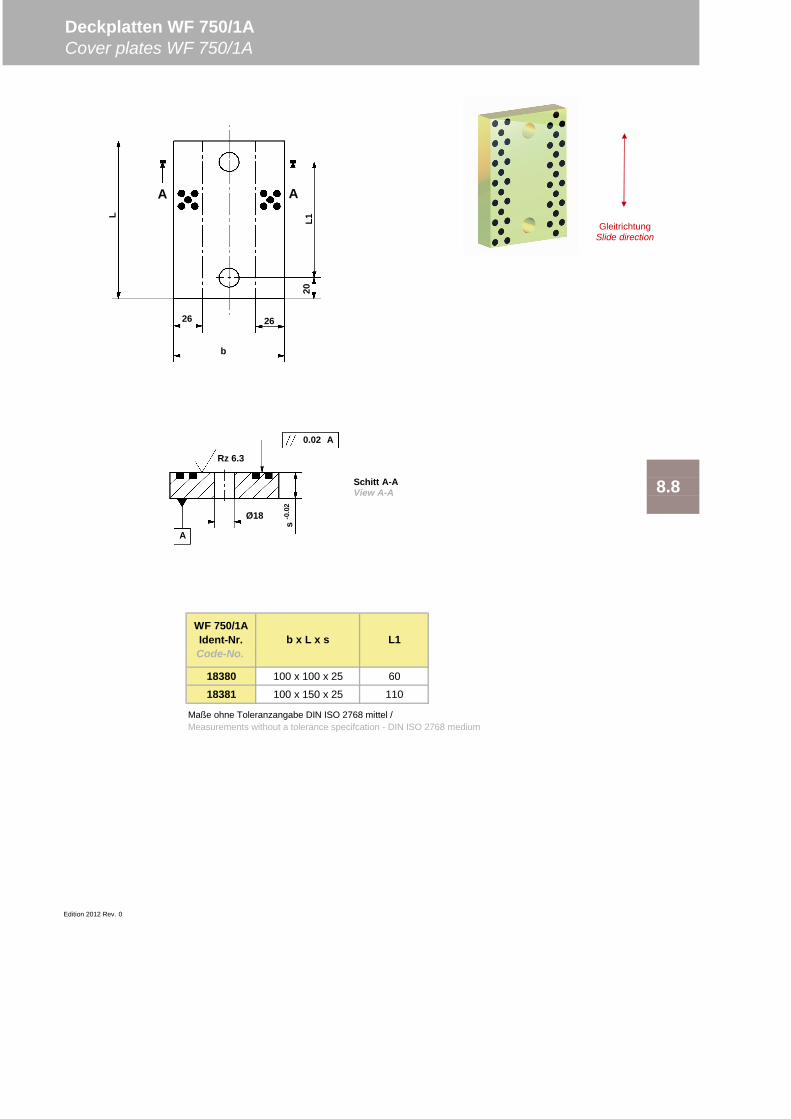
18380 100 x 100 x 25 60
18381 100 x 150 x 25 110
Edition 2012 Rev. 0
8.8
Maße ohne Toleranzangabe DIN ISO 2768 mittel /Measurements without a tolerance specifcation - DIN ISO 2768 medium
Deckplatten WF 750/1ACover plates WF 750/1A
WF 750/1AIdent-Nr.Code-No.
b x L x s L1
26 26
b
20L1L
A A
GleitrichtungSlide direction
0.02
Ø18
Rz 6.3
s-0
.02
A
A
Schitt A-AView A-A

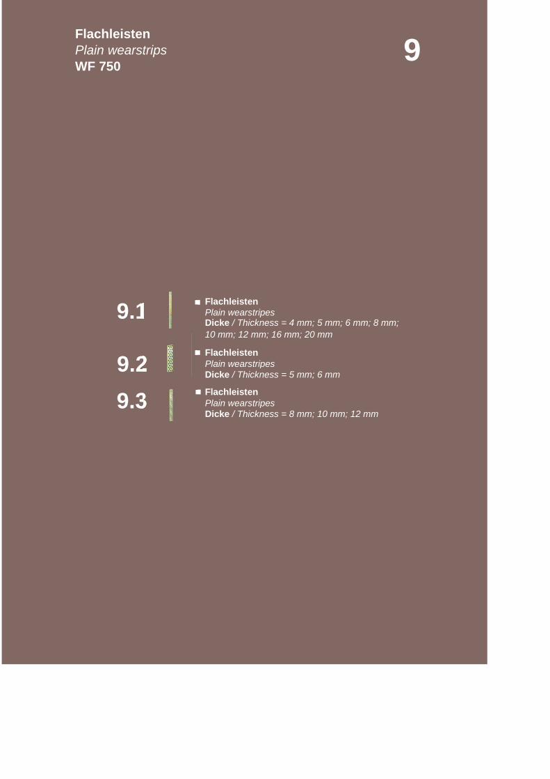
Plain wearstripesDicke / Thickness = 4 mm; 5 mm; 6 mm; 8 mm;
Plain wearstripes
Plain wearstripes
10 mm; 12 mm; 16 mm; 20 mm
Flachleisten
Dicke / Thickness = 5 mm; 6 mm
Flachleisten
Dicke / Thickness = 8 mm; 10 mm; 12 mm
9.29.3
FlachleistenPlain wearstripsWF 750
9
9.1 Flachleisten
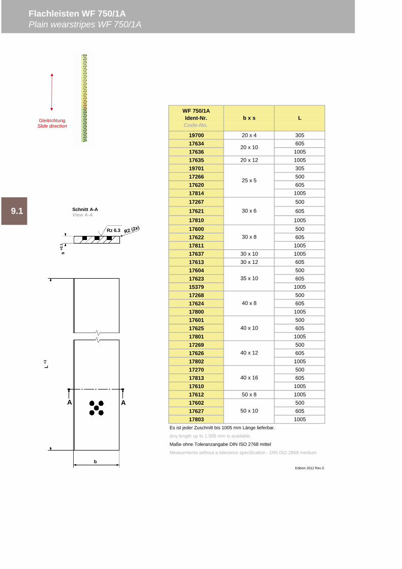
19700 20 x 4 30517634 60517636 100517635 20 x 12 100519701 30517266 50017620 60517814 100517267 500
17621 605
17810 100517600 50017622 60517811 100517637 30 x 10 100517613 30 x 12 60517604 50017623 60515379 100517268 50017624 60517800 100517601 50017625 60517801 100517269 50017626 60517802 100517270 50017813 60517610 100517612 50 x 8 100517602 50017627 60517803 1005
Es ist jeder Zuschnitt bis 1005 mm Länge lieferbar.
Any length up to 1.005 mm is available.
Maße ohne Toleranzangabe DIN ISO 2768 mittel
Measurments without a tolerance specification - DIN ISO 2868 medium
Edition 2012 Rev.0
WF 750/1AIdent-Nr.Code-No.
b x s L
20 x 10
25 x 5
Flachleisten WF 750/1APlain wearstripes WF 750/1A
9.1 30 x 6
30 x 8
35 x 10
40 x 8
40 x 10
40 x 12
40 x 16
50 x 10
s+0
.1
Rz 6.3
L+1
A A
b
Schnitt A-AView A-A
GleitrichtungSlide direction
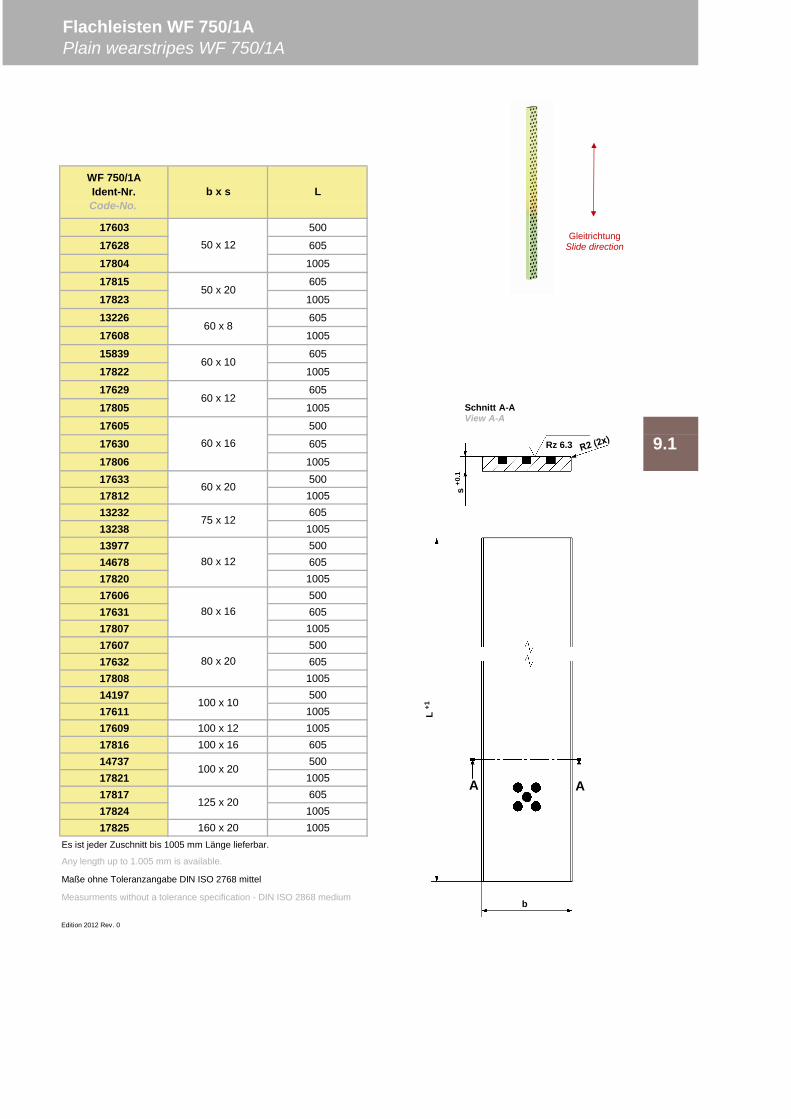
17603 500
17628 605
17804 1005
17815 605
17823 1005
13226 605
17608 1005
15839 605
17822 1005
17629 605
17805 1005
17605 500
17630 605
17806 100517633 50017812 100513232 60513238 100513977 50014678 60517820 100517606 50017631 60517807 100517607 50017632 60517808 100514197 50017611 100517609 100 x 12 100517816 100 x 16 60514737 50017821 100517817 60517824 100517825 160 x 20 1005
Es ist jeder Zuschnitt bis 1005 mm Länge lieferbar.
Any length up to 1.005 mm is available.
Maße ohne Toleranzangabe DIN ISO 2768 mittel
Measurments without a tolerance specification - DIN ISO 2868 medium
Edition 2012 Rev. 0
100 x 20
125 x 20
75 x 12
80 x 12
80 x 16
80 x 20
100 x 10
60 x 8
60 x 10
60 x 12
60 x 16
60 x 20
WF 750/1AIdent-Nr.Code-No.
b x s L
50 x 12
50 x 20
Flachleisten WF 750/1APlain wearstripes WF 750/1A
9.1s
+0.1
Rz 6.3
L+1
A A
b
Schnitt A-AView A-A
GleitrichtungSlide direction
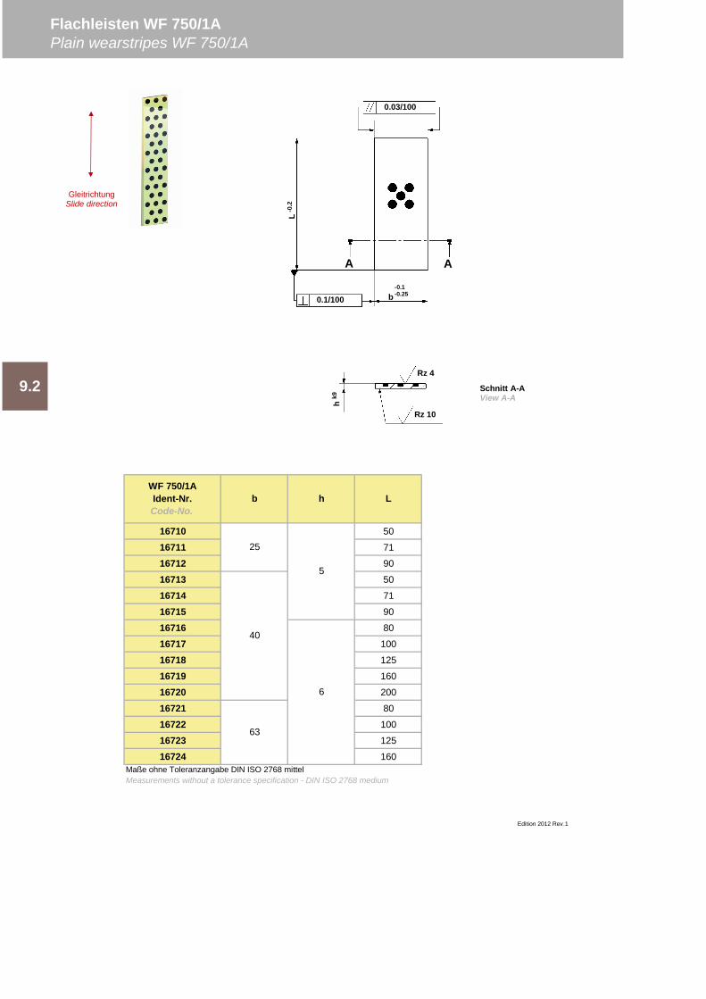
16710 50
16711 71
16712 90
16713 50
16714 71
16715 90
16716 80
16717 100
16718 125
16719 160
16720 200
16721 80
16722 100
16723 125
16724 160
Flachleisten WF 750/1APlain wearstripes WF 750/1A
WF 750/1AIdent-Nr.Code-No.
b h L
Edition 2012 Rev.1
9.2
25
5
40
6
63
Maße ohne Toleranzangabe DIN ISO 2768 mittelMeasurements without a tolerance specification - DIN ISO 2768 medium
Rz 4
hk9
Rz 10
L-0
.2
0.03/100
A A
0.1/100 b-0.1-0.25
Schnitt A-AView A-A
GleitrichtungSlide direction
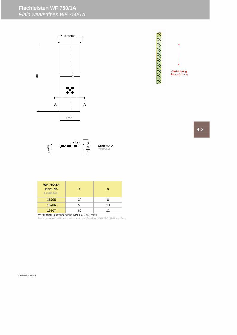
16705 32 8
16706 50 10
16707 80 12
Edition 2012 Rev. 1
WF 750/1AIdent-Nr.Code-No.
b s
Maße ohne Toleranzangabe DIN ISO 2768 mittelMeasurements without a tolerance specification - DIN ISO 2768 medium
Flachleisten WF 750/1APlain wearstripes WF 750/1A
9.3
0.04Rz 4
s+0
.05
500
b ±0.2
0.05/100
A A
Schnitt A-AView A-A
GleitrichtungSlide direction

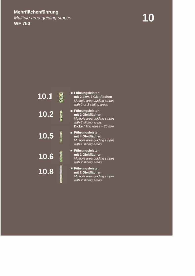
mit 2 bzw. 3 GleitflächenMultiple area guiding stripes
mit 2 GleitflächenMultiple area guiding stripeswith 2 sliding areas
mit 4 GleitflächenMultiple area guiding stripes
mit 2 GleitflächenMultiple area guiding stripes
mit 2 GleitflächenMultiple area guiding stripeswith 2 sliding areas
Dicke / Thickness = 25 mm
with 4 sliding areas
Führungsleisten
with 2 sliding areas
Führungsleisten
10.2
10.6
10.1
10.8
10
10.5
Führungsleisten
with 2 or 3 sliding areas
Führungsleisten
Führungsleisten
MehrflächenführungMultiple area guiding stripesWF 750
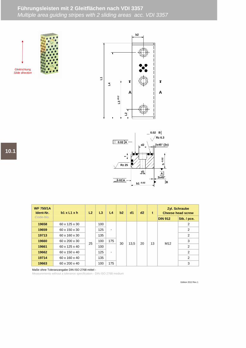
DIN 912 Stk. / pce.19658 60 x 125 x 30 100 2
19659 60 x 150 x 30 125 2
19713 60 x 160 x 30 135 2
19660 60 x 200 x 30 100 175 3
19661 60 x 125 x 40 100 2
19662 60 x 150 x 40 125 2
19714 60 x 160 x 40 135 2
19663 60 x 200 x 40 100 175 3
Edition 2012 Rev.1
10.1
WF 750/1AIdent-Nr.Code-No.
Zyl. SchraubeCheese head screw
13
t
Führungsleisten mit 2 Gleitflächen nach VDI 3357Multiple area guiding stripes with 2 sliding areas acc. VDI 3357
Maße ohne Toleranzangabe DIN ISO 2768 mittel -Measurements without a tolerance specification - DIN ISO 2768 medium
M12
-
-
25 30
b1 x L1 x h L2 L3 L4 b2 d1 d2
13,5 20
b2
L2
L4
A
L3±0
.2
L1
3x45°
d1
Rz 6.3
d2
h-0
.02
t
Rz 25
A
0.02 B
0.02 A
A
b1 -0.02
0.02
B
GleitrichtungSlide direction
2x45° (3x)
A
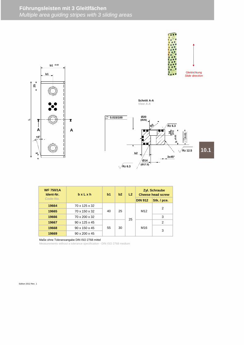
DIN 912 Stk. / pce.19664 70 x 125 x 32
19665 70 x 150 x 32
19666 70 x 200 x 32 3
19667 90 x 125 x 45 2
19668 90 x 150 x 45
19669 90 x 200 x 45
Edition 2012 Rev. 1
Führungsleisten mit 3 GleitlfächenMultiple area guiding stripes with 3 sliding areas
10.1
Maße ohne Toleranzangabe DIN ISO 2768 mittelMeasurements without a tolerance specification - DIN ISO 2768 medium
Zyl. SchraubeCheese head screw
25
30
b1
40
55
25
M12
M16
WF 750/1AIdent-Nr.Code-No.
b x L x h b2 L2
2
3
Schnitt A-AView A-A
16 (21)
Ø20(Ø26)
Rz 6.3
Rz 12.5
0.01
3x45°
0.015/100
Rz 6.3
b2
Ø14(Ø17.5)
b1 -0.02
b1
25
L
5
A A
GleitrichtungSlide direction
h±0
.02

Edition 2012 Rev.0
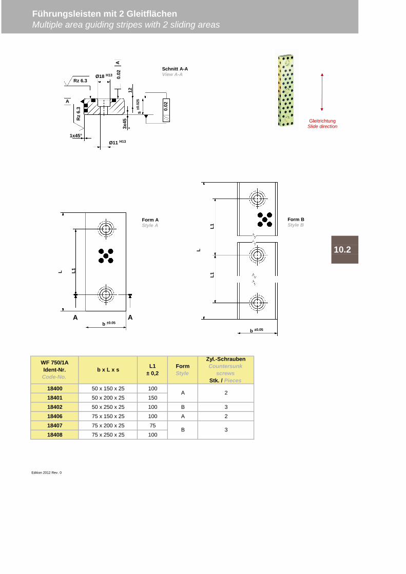
18400 50 x 150 x 25 100
18401 50 x 200 x 25 150
18402 50 x 250 x 25 100 B 3
18406 75 x 150 x 25 100 A 2
18407 75 x 200 x 25 75
18408 75 x 250 x 25 100
Edition 2012 Rev. 0
Führungsleisten mit 2 GleitflächenMultiple area guiding stripes with 2 sliding areas
10.2
A
B
2
3
WF 750/1AIdent-Nr.Code-No.
b x L x s L1± 0,2
FormStyle
Zyl.-SchraubenCountersunk
screwsStk. / Pieces
b ±0.05
L L1
A A
b ±0.05
L
L1L1
Form AStyle A
Form BStyle B
GleitrichtungSlide direction
0.02
Rz 6.3
Ø11 H13
Ø18 H13
A
0.02
A
s±0
.025
123x
45°
1x45°
Rz
6.3
Schnitt A-AView A-A
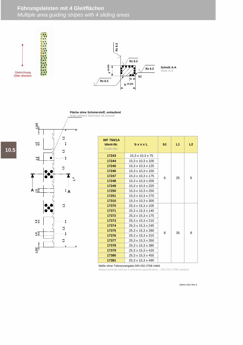
17243 15,3 x 10,3 x 7517244 15,3 x 10,3 x 10017245 15,3 x 10,3 x 12517246 15,3 x 10,3 x 15017247 15,3 x 10,3 x 17517248 15,3 x 10,3 x 20017249 15,3 x 10,3 x 22517250 15,3 x 10,3 x 25017251 15,3 x 10,3 x 27517310 15,3 x 10,3 x 30017370 25,3 x 15,3 x 10517371 25,3 x 15,3 x 14017372 25,3 x 15,3 x 17517373 25,3 x 15,3 x 21017374 25,3 x 15,3 x 24517375 25,3 x 15,3 x 28017376 25,3 x 15,3 x 31517377 25,3 x 15,3 x 35017378 25,3 x 15,3 x 38517379 25,3 x 15,3 x 42017380 25,3 x 15,3 x 45517381 25,3 x 15,3 x 490
Führungsleisten mit 4 GleitflächenMultiple area guiding stripes with 4 sliding areas
Edition 2012 Rev.0
10.5
WF 750/1AIdent-Nr.Code-No.
b x s x L b1 L1 L2
Maße ohne Toleranzangabe DIN ISO 2768 mittelMeasurements without a tolerance specification - DIN ISO 2768 medium
8 35 8
6 25 6
Rz
6.3
Rz 6.3
Rz 6.3
Rz 6.3b1
b ±0.025
s±0
.025 Schnitt A-A
View A-A
L1L1
L1L1
L1L1
L-2
L2/2
L2L2
L2L2
L2L2
/2
Fläche ohne Schmierstoff, umlaufendArea without lubricant all around
A A
GleitrichtungSlide direction
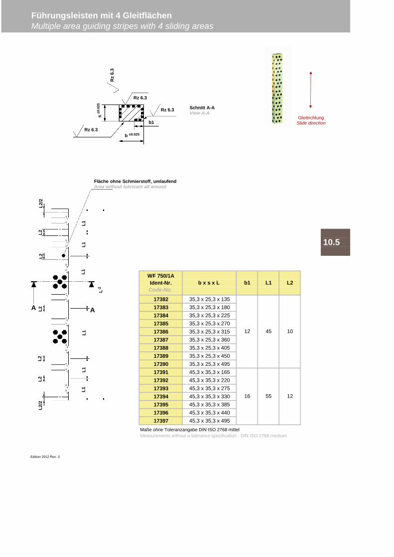
17382 35,3 x 25,3 x 13517383 35,3 x 25,3 x 18017384 35,3 x 25,3 x 22517385 35,3 x 25,3 x 27017386 35,3 x 25,3 x 31517387 35,3 x 25,3 x 36017388 35,3 x 25,3 x 40517389 35,3 x 25,3 x 45017390 35,3 x 25,3 x 49517391 45,3 x 35,3 x 16517392 45,3 x 35,3 x 22017393 45,3 x 35,3 x 27517394 45,3 x 35,3 x 33017395 45,3 x 35,3 x 38517396 45,3 x 35,3 x 44017397 45,3 x 35,3 x 495
Edition 2012 Rev. 0
10.5
Führungsleisten mit 4 GleitflächenMultiple area guiding stripes with 4 sliding areas
Maße ohne Toleranzangabe DIN ISO 2768 mittelMeasurements without a tolerance specification - DIN ISO 2768 medium
12 45 10
16 55 12
WF 750/1AIdent-Nr.Code-No.
b x s x L b1 L1 L2
GleitrichtungSlide direction
Rz
6.3
Rz 6.3
Rz 6.3
Rz 6.3b1
b ±0.025
s±0
.025
L1L1
L1L1
L1L1
L-2
L2/2
L2L2
L2L2
L2L2
/2
Fläche ohne Schmierstoff, umlaufendArea without lubricant all around
A A
Schnitt A-AView A-A
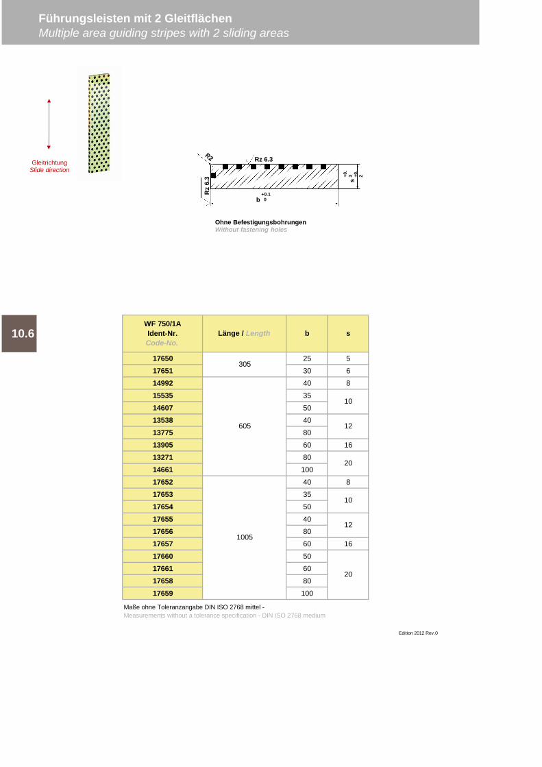
17650 25 5
17651 30 6
14992 40 8
15535 35
14607 50
13538 40
13775 80
13905 60 16
13271 80
14661 100
17652 40 8
17653 35
17654 50
17655 40
17656 80
17657 60 16
17660 50
17661 60
17658 80
17659 100
Führungsleisten mit 2 GleitflächenMultiple area guiding stripes with 2 sliding areas
10
12
20
10.6
Edition 2012 Rev.0
1005
10
12
20
Maße ohne Toleranzangabe DIN ISO 2768 mittel -Measurements without a tolerance specification - DIN ISO 2768 medium
605
WF 750/1AIdent-Nr.Code-No.
Länge / Length b s
305
Rz
6.3
Rz 6.3
+0.10b
+0.
3 +0.
2
s
Ohne BefestigungsbohrungenWithout fastening holes
GleitrichtungSlide direction
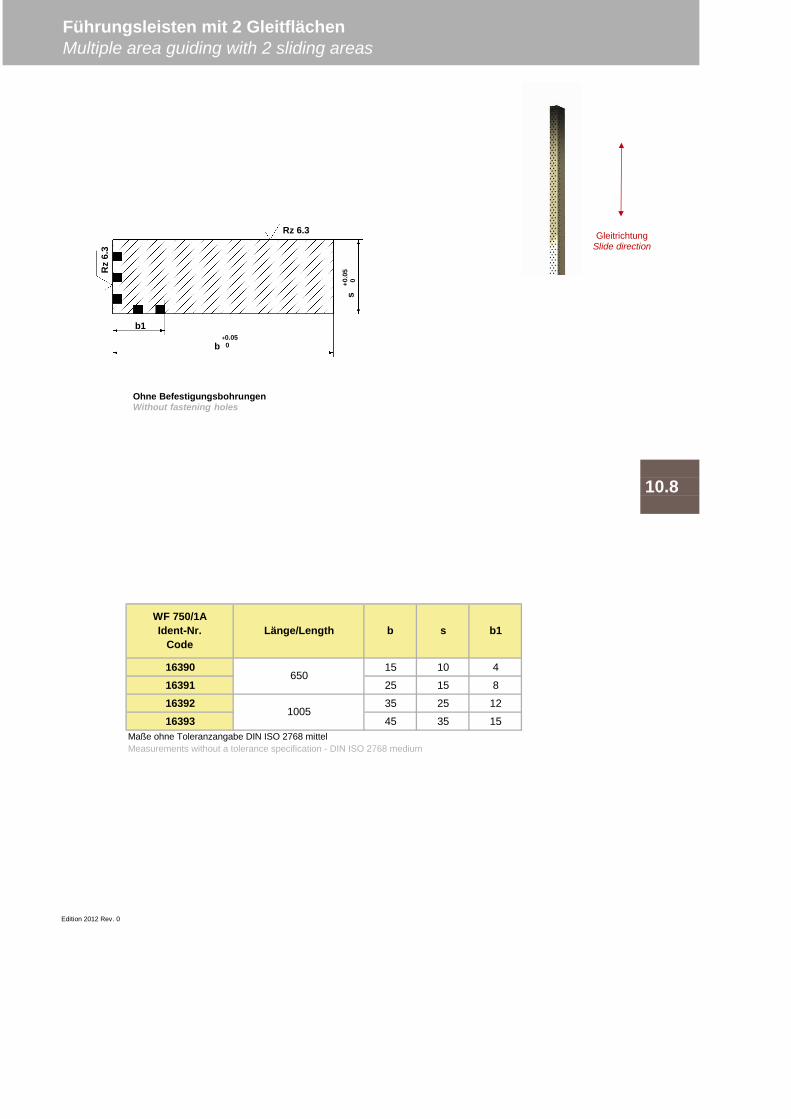
16390 15 10 4
16391 25 15 8
16392 35 25 12
16393 45 35 15
Edition 2012 Rev. 0
650
1005
Maße ohne Toleranzangabe DIN ISO 2768 mittelMeasurements without a tolerance specification - DIN ISO 2768 medium
WF 750/1AIdent-Nr.
CodeLänge/Length b s b1
Führungsleisten mit 2 GleitflächenMultiple area guiding with 2 sliding areas
10.8
Rz
6.3
Rz 6.3
+0.050b
+0.0
50
s
b1
Ohne BefestigungsbohrungenWithout fastening holes
GleitrichtungSlide direction

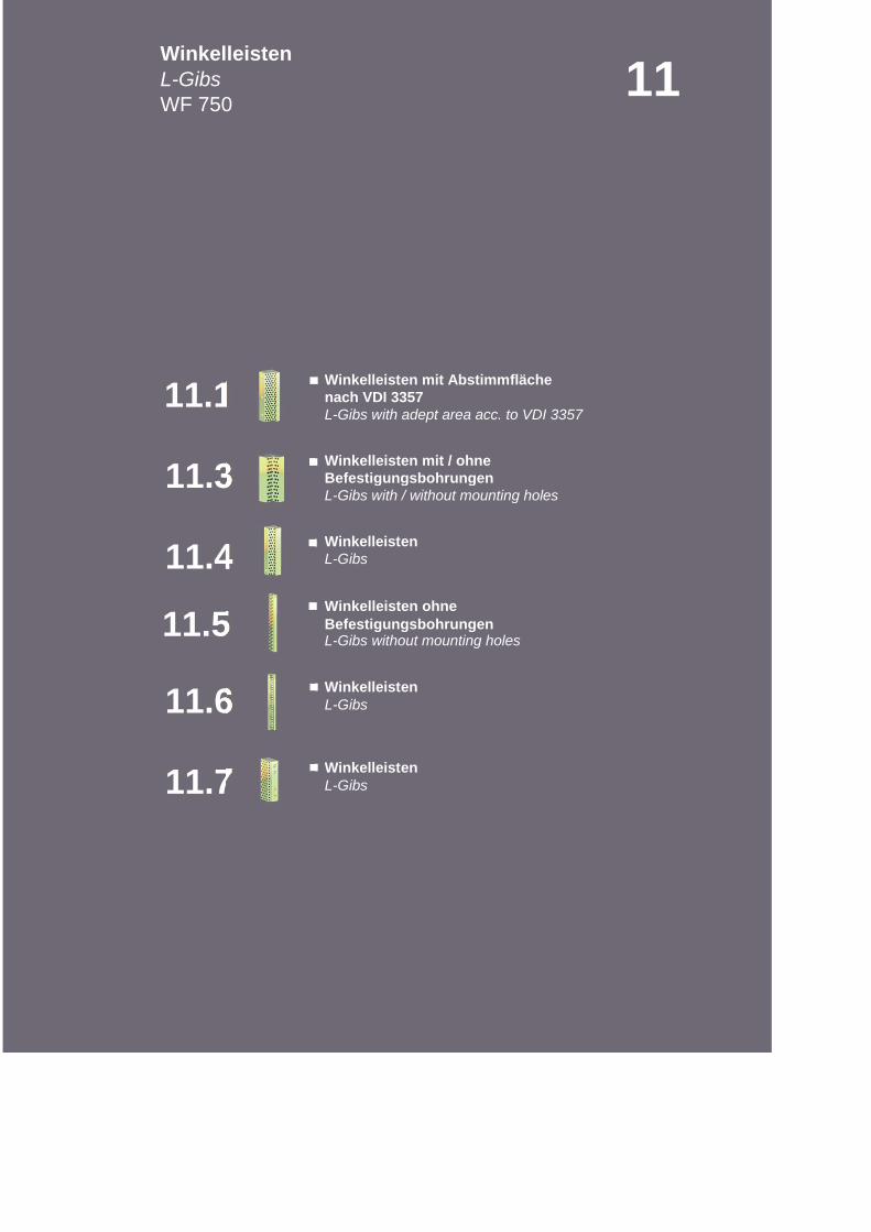
nach VDI 3357
Befestigungsbohrungen
L-Gibs
Befestigungsbohrungen
L-Gibs
L-Gibs
Winkelleisten
L-Gibs with / without mounting holes
11WinkelleistenL-GibsWF 750
Winkelleisten mit Abstimmfläche
L-Gibs with adept area acc. to VDI 3357
Winkelleisten mit / ohne
11.4
11.3
11.1
Winkelleisten ohne
L-Gibs without mounting holes
Winkelleisten
Winkelleisten
11.5
11.7
11.6
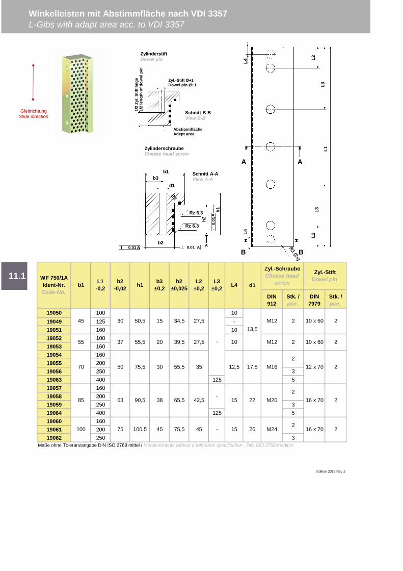
d1
19050 100 1019049 125 -19051 160 1019052 10019053 16019054 16019055 20019056 250 319063 400 125 519057 16019058 20019059 250 319064 400 125 519060 16019061 20019062 250 3
Maße ohne Toleranzangabe DIN ISO 2768 mittel / Measurements without a tolerance specification - DIN ISO 2768 medium
Edition 2012 Rev.2
L2±0,2
WF 750/1AIdent-Nr.Code-No.
b1
55
70
27,5
b3±0,2
1530 50,5 34,5
30
L1-0,2
b2-0,02 h1 h2
±0,025
85
45
100
11.1
Winkelleisten mit Abstimmfläche nach VDI 3357L-Gibs with adapt area acc. to VDI 3357
Zyl.-StiftDowel pin
DIN7979
Stk. /pce.
13,5
2 10 x 60 2
2
L3±0,2 L4
Zyl.-SchraubeCheese head
screw
DIN912
Stk. /pce.
M16 12 x 7050 75,52
-27,5
17,5
2 10 x 60M12
75 45 -45
38
75,5100,5 16 x 70 215
15 16 x 7022
26
2
2M24
M20
2
37 55,5 39,5
63 90,5 65,5 42,5-
M12
12,5
1020
2
55,5 35
L1
L2
L3
L4
A
B
AbstimmflächeAdept area
1/2
Zyl.
Stift
läng
e1/
2le
ngth
ofdo
wel
pin
Zyl.-Stift Ø+1Dowel pin Ø+1
Schnitt B-BView B-B
GleitrichtungSlide direction
0.01
b1
0.01
0.01
A A A
A
b3
b2
Rz 6.3
Rz 6.3 h1
h2
Schnitt A-AView A-A
ZylinderstiftDowel pin
ZylinderschraubeCheese head screw
A
BL4
L2L3
d1
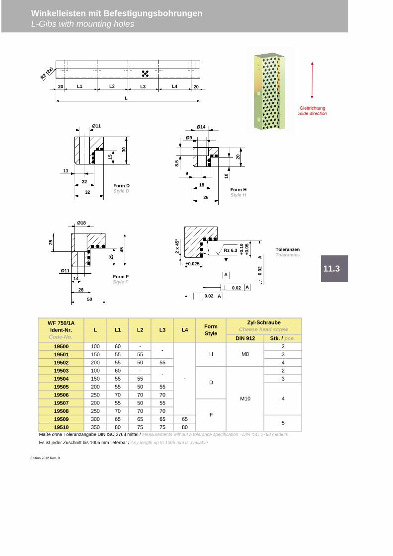
DIN 912 Stk. / pce.19500 100 60 - 219501 150 55 55 319502 200 55 50 55 419503 100 60 - 219504 150 55 55 319505 200 55 50 5519506 250 70 70 7019507 200 55 50 5519508 250 70 70 7019509 300 65 65 65 6519510 350 80 75 75 80
Maße ohne Toleranzangabe DIN ISO 2768 mittel / Measurements without a tolerance specification - DIN ISO 2768 medium
Es ist jeder Zuschnitt bis 1005 mm lieferbar / Any length up to 1005 mm is available
Edition 2012 Rev. 0
4
5
FormStyle
Zyl-SchraubeCheese head screw
-
--
H
D
F
M8
M10
L4WF 750/1AIdent-Nr.Code-No.
L L1 L2 L3
11.3
Winkelleisten mit BefestigungsbohrungenL-Gibs with mounting holes
L1 L2 L3 L420 20
L
Ø11
11
22
32
15
30Ø14
Ø9
9
18
26
10
20
8.5
Ø11
Ø18
14
28
50
25
25
45
0.02
0.02
0.02
A
A
A
A±0.025
+0.1
0+0
.05
Rz 6.32x
45°
Form DStyle D Form H
Style H
Form FStyle F
ToleranzenTolerances
GleitrichtungSlide direction
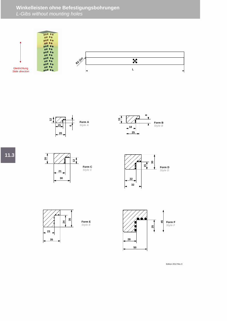
Winkelleisten ohne BefestigungsbohrungenL-Gibs without mounting holes
Edition 2012 Rev.0
11.3
L
12
615
20
Form AStyle A
18
25
15
8
Form BStyle B
15
30
22
32
Form DStyle D
23
35
24
35 Form EStyle E
25
45
28
50
Form FStyle F
21
30
20
12
Form CStyle C
GleitrichtungSlide direction
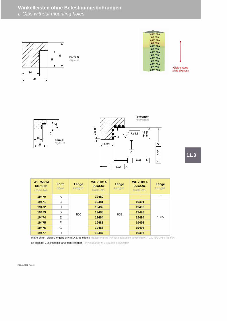
19470 A 19480 - -
19471 B 19481 1949119472 C 19482 1949219473 D 19483 1949319474 E 19484 1949419475 F 19485 1949519476 G 19486 1949619477 H 19487 19497
Maße ohne Toleranzangabe DIN ISO 2768 mittel / Measurements without a tolerance specification - DIN ISO 2768 medium
Es ist jeder Zuschnitt bis 1005 mm lieferbar / Any length up to 1005 mm is available
Edition 2012 Rev. 0
11.3
LängeLength
500 6051005
Winkelleisten ohne BefestigungsbohrungenL-Gibs without mounting holes
WF 750/1AIdent-Nr.Code-No.
FormStyle
LängeLength
WF 750/1AIdent-Nr.Code-No.
LängeLength
WF 750/1AIdent-Nr.Code-No.
0.02
0.020.
02A
A
A+0.025+0
.10
+0.0
5
Rz 6.32x
45°
A
34
34
50
50
Form GStyle G
18
26
1020
Form HStyle H
ToleranzenTolerances
GleitrichtungSlide direction
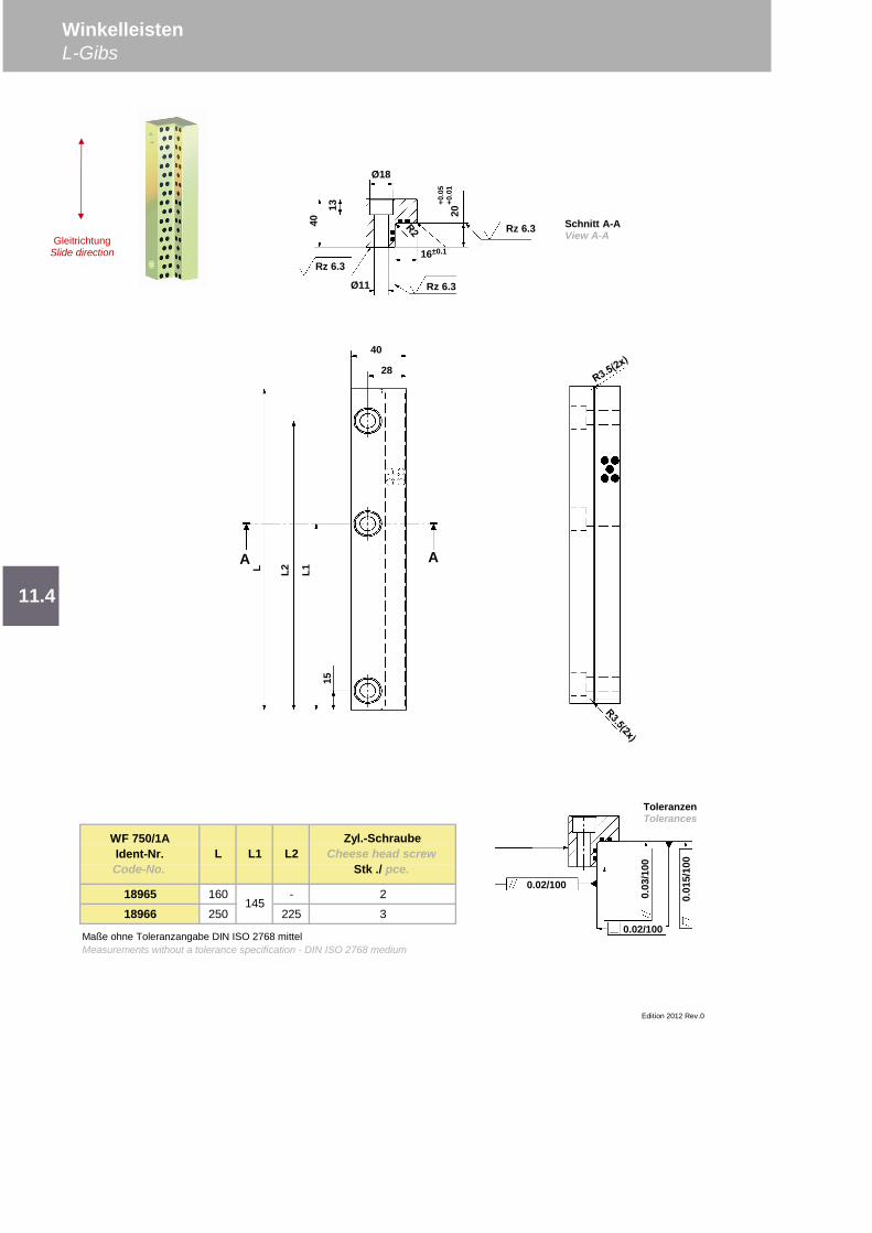
18965 160 - 2
18966 250 225 3
WinkelleistenL-Gibs
11.4
Edition 2012 Rev.0
WF 750/1AIdent-Nr.Code-No.
Zyl.-SchraubeCheese head screw
Stk ./ pce.L L1 L2
Maße ohne Toleranzangabe DIN ISO 2768 mittelMeasurements without a tolerance specification - DIN ISO 2768 medium
145
40
L1
28
L2L
15
A A
0.02/100
0.02/100
0.03
/100
0.01
5/10
0
ToleranzenTolerances
Ø11
Ø18
Rz 6.3
13
Rz 6.3
Rz 6.316±0.1
40
20+0
.05
+0.0
1
Schnitt A-AView A-AGleitrichtung
Slide direction
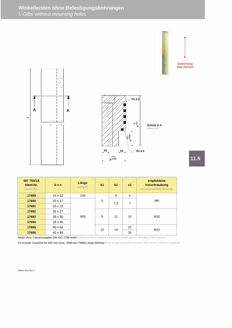
17689 15 x 12 205 6 5
17690 20 x 17
17691 20 x 22
17692 28 x 27
17693 28 x 36
17694 28 x 46
17695 40 x 66 22
17696 40 x 86 26Maße ohne Toleranzangabe DIN ISO 2768 mittel / Measurements without a tolerance specification - DIN ISO 2768 medium
Es ist jeder Zuschnitt bis 605 mm (max. 2085 bei 17689) Länge lieferbar / Any length up to 605 mm (ma. 205 mm for 17689) is available
Edition 2012 Rev. 1
Winkelleisten ohne BefestigungsbohrungenL-Gibs without mounting holes
11.5
WF 750/1AIdent-Nr.Code-No.
b x s LängeLength b1 b2
1011
14
empfohleneVerschraubung
recommended bolting
605
5
8
12
M6
M10
M12
77,5
s1
L
Schnitt A-AView A-A
A A
GleitrichtungSlide direction
b+0.1+0.05
b2 b1 Rz 6.3
s+0.1
+0.0
5
s0 -0.2
Rz 6.3
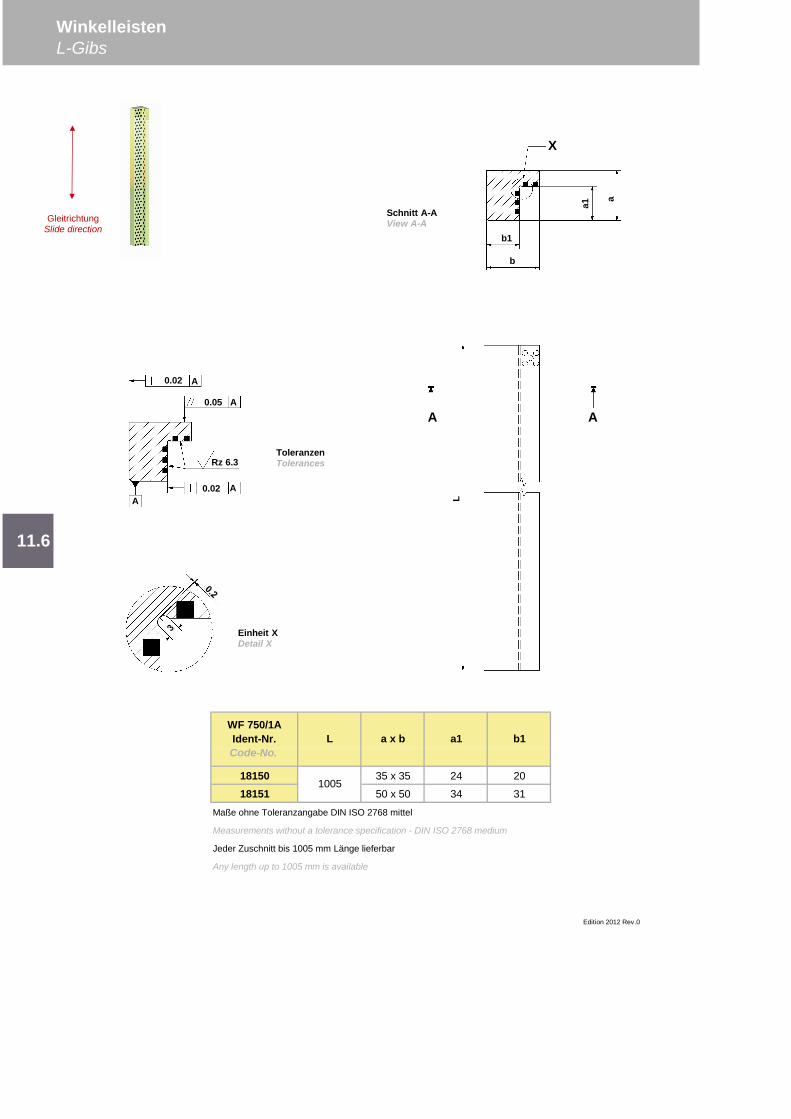
18150 35 x 35 24 20
18151 50 x 50 34 31
Maße ohne Toleranzangabe DIN ISO 2768 mittel
Measurements without a tolerance specification - DIN ISO 2768 medium
Jeder Zuschnitt bis 1005 mm Länge lieferbar
Any length up to 1005 mm is available
11.6
WinkelleistenL-Gibs
Edition 2012 Rev.0
b1
1005
WF 750/1AIdent-Nr.Code-No.
L a x b a1
Schnitt A-AView A-A
b
b1
a1
X
a
ToleranzenTolerances
L
A A
Einheit XDetail X
GleitrichtungSlide direction
0.02 A
0.05 A
0.02 AA
Rz 6.3
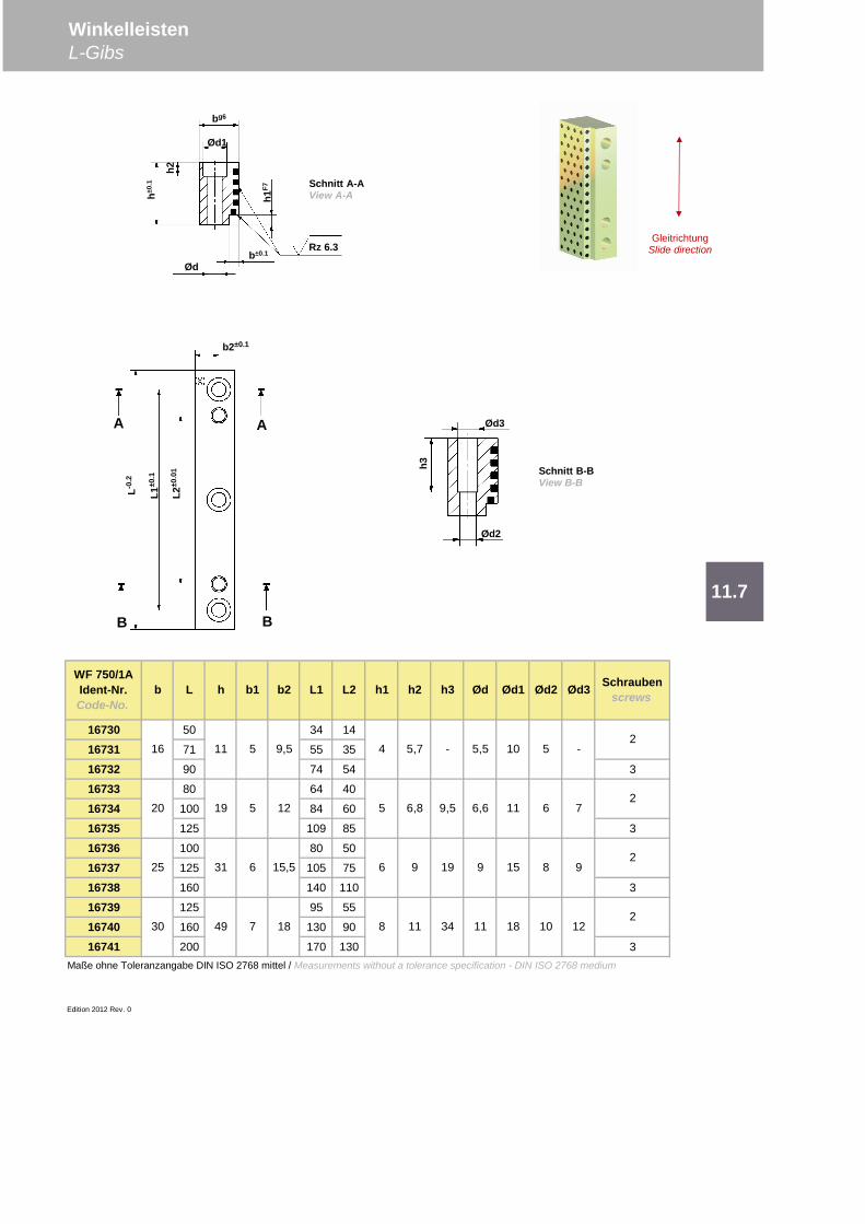
16730 50 34 14
16731 71 55 35
16732 90 74 54 3
16733 80 64 40
16734 100 84 60
16735 125 109 85 3
16736 100 80 50
16737 125 105 75
16738 160 140 110 3
16739 125 95 55
16740 160 130 90
16741 200 170 130 3Maße ohne Toleranzangabe DIN ISO 2768 mittel / Measurements without a tolerance specification - DIN ISO 2768 medium
Edition 2012 Rev. 0
2
82
Schraubenscrews
42
52
12
h3 Ød Ød1
11 34 11 18
WF 750/1AIdent-Nr.Code-No.
b L h b1 b2 L1 L2 h1 h2
1030 49 7 18
19 9 15 8 925 31 6 15,5 96
20 19 5 12
16 11 5 9,5
7
5,7 - 5,5 10 5
6,8 9,5 6,6 11 6
-
Ød2 Ød3
11.7
WinkelleistenL-Gibs
Rz 6.3
Ødh1
F7
h±0.1
h2
Ød1
bg6
b±0.1
A
b2±0.1
L1±0
.1
L2±0
.01
L-0.2
A
BB
Ød3
Ød2
h3
Schnitt A-AView A-A
Schnitt B-BView B-B
GleitrichtungSlide direction

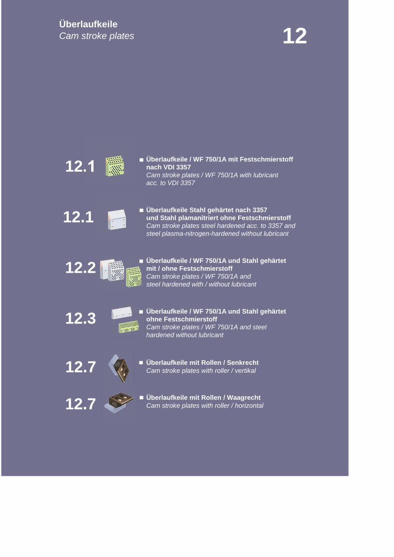
nach VDI 3357Cam stroke plates / WF 750/1A with lubricant
und Stahl plamanitriert ohne FestschmierstoffCam stroke plates steel hardened acc. to 3357 and
mit / ohne FestschmierstoffCam stroke plates / WF 750/1A and
ohne FestschmierstoffCam stroke plates / WF 750/1A and steel
Cam stroke plates with roller / vertikal
Cam stroke plates with roller / horizontal
12
12.3
acc. to VDI 3357
Überlaufkeile / WF 750/1A mit Festschmierstoff
Überlaufkeile Stahl gehärtet nach 3357
Überlaufkeile / WF 750/1A und Stahl gehärtet
Überlaufkeile / WF 750/1A und Stahl gehärtet
ÜberlaufkeileCam stroke plates
steel plasma-nitrogen-hardened without lubricant
steel hardened with / without lubricant
12.1
12.2
12.1
hardened without lubricant
Überlaufkeile mit Rollen / Senkrecht
Überlaufkeile mit Rollen / Waagrecht
12.7
12.7
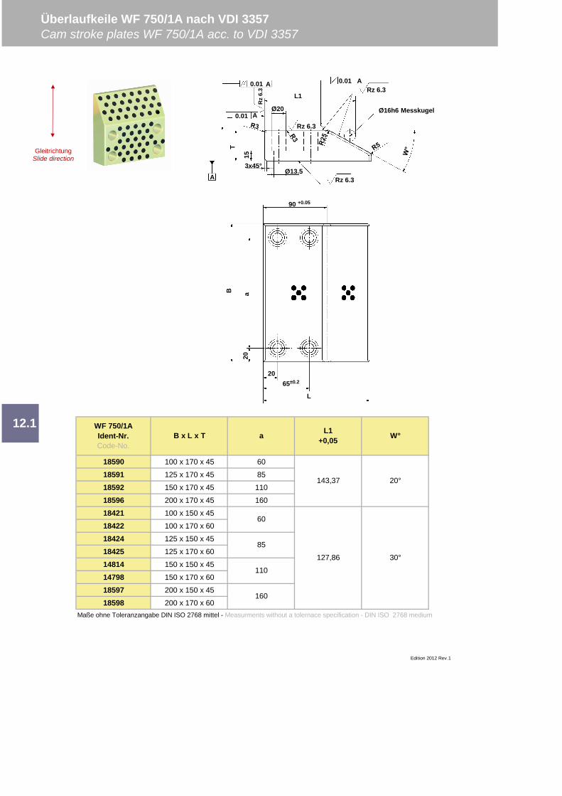
18590 100 x 170 x 45 60
18591 125 x 170 x 45 85
18592 150 x 170 x 45 110
18596 200 x 170 x 45 160
18421 100 x 150 x 45
18422 100 x 170 x 60
18424 125 x 150 x 45
18425 125 x 170 x 60
14814 150 x 150 x 45
14798 150 x 170 x 60
18597 200 x 150 x 45
18598 200 x 170 x 60Maße ohne Toleranzangabe DIN ISO 2768 mittel - Measurments without a tolernace specification - DIN ISO 2768 medium
Überlaufkeile WF 750/1A nach VDI 3357Cam stroke plates WF 750/1A acc. to VDI 3357
127,86
60
85
12.1L1
+0,05
Edition 2012 Rev.1
W°
143,37 20°
30°
110
160
WF 750/1AIdent-Nr.Code-No.
B x L x T a
GleitrichtungSlide direction
20
B a
2065±0.2
L
90 +0.05
A0.01
L1
T
0.01
0.01A
A
A
Ø20
Rz 6.3
Rz 6.3
Ø13.5Rz 6.3
15
3x45°
Ø16h6 Messkugel
Rz
6.3
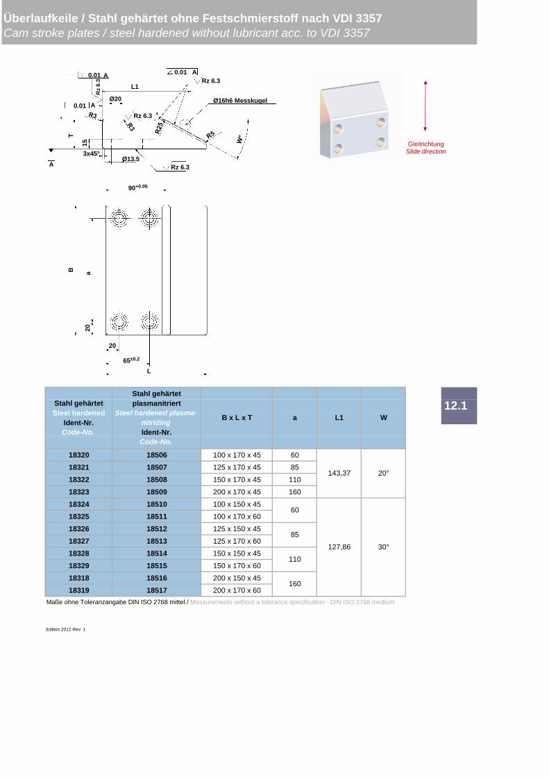
18320 18506 100 x 170 x 45 60
18321 18507 125 x 170 x 45 85
18322 18508 150 x 170 x 45 110
18323 18509 200 x 170 x 45 160
18324 18510 100 x 150 x 45
18325 18511 100 x 170 x 60
18326 18512 125 x 150 x 45
18327 18513 125 x 170 x 60
18328 18514 150 x 150 x 45
18329 18515 150 x 170 x 60
18318 18516 200 x 150 x 45
18319 18517 200 x 170 x 60Maße ohne Toleranzangabe DIN ISO 2768 mittel / Measurements without a tolerance specification - DIN ISO 2768 medium
Edition 2012 Rev. 1
12.1
127,86 30°
Stahl gehärtetplasmanitriert
Steel hardened plasma-nitridingIdent-Nr.Code-No.
60
85
110
160
143,37 20°
Überlaufkeile / Stahl gehärtet ohne Festschmierstoff nach VDI 3357Cam stroke plates / steel hardened without lubricant acc. to VDI 3357
Stahl gehärtetSteel hardened
Ident-Nr.Code-No.
B x L x T a L1 W
20
B a
20
65±0.2
L
90+0.05
GleitrichtungSlide direction
A0.01
L1
T
0.01
0.01A
A
A
Ø20
Rz 6.3
Rz 6.3
Ø13.5Rz 6.3
15
3x45°
Ø16h6 MesskugelR
z6.
3
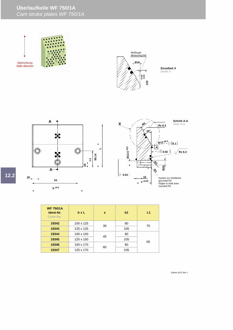
19342 100 x 125 80
19343 125 x 125 105
19344 100 x 150 80
19345 125 x 150 105
19346 100 x 170 80
19347 125 x 170 105
Überlaufkeile WF 750/1ACam stroke plates WF 750/1A
12.2
Edition 2012 Rev.1
WF 750/1AIdent-Nr.Code-No.
b x L s b1 L1
30
45
60
70
65
0.1
X
Kanten zur Gleitlächegerundet R3Edges to slide arearounded R3
0.02A
0.01
Rz 6.3
s ±0.05
15
Ø13
.5H
13Rz 6.3
Ø20
Schnitt A-AView A-A
20b1
b ±0.5
20
L1 95.1
4L
A
MeßkugelMeasuring ball
Ø16
133
+0.0
5-0
.00
Einzelheit XDetail X
GleitrichtungSlide direction
A
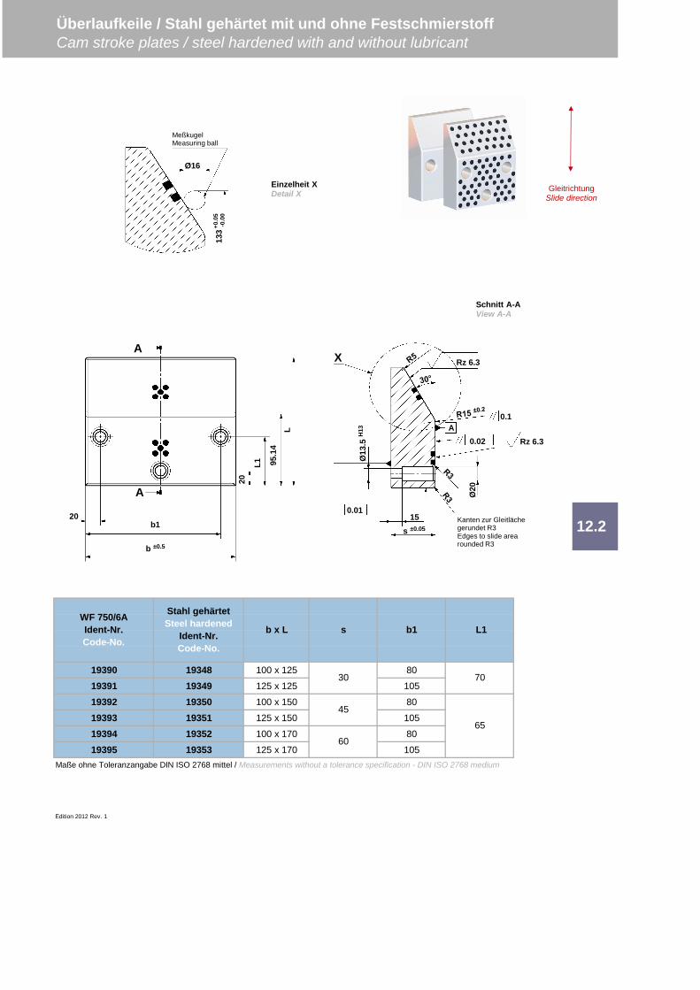
19390 19348 100 x 125 80
19391 19349 125 x 125 105
19392 19350 100 x 150 80
19393 19351 125 x 150 105
19394 19352 100 x 170 80
19395 19353 125 x 170 105Maße ohne Toleranzangabe DIN ISO 2768 mittel / Measurements without a tolerance specification - DIN ISO 2768 medium
Edition 2012 Rev. 1
Überlaufkeile / Stahl gehärtet mit und ohne FestschmierstoffCam stroke plates / steel hardened with and without lubricant
12.2
b1 L1
45
60
70
65
WF 750/6AIdent-Nr.Code-No.
Stahl gehärtetSteel hardened
Ident-Nr.Code-No.
b x L s
30
MeßkugelMeasuring ball
Ø16
133+0
.05
-0.0
0
Einzelheit XDetail X Gleitrichtung
Slide direction
0.1
X
Kanten zur Gleitlächegerundet R3Edges to slide arearounded R3
0.02A
0.01
Rz 6.3
s ±0.05
15
Ø13
.5H
13Rz 6.3
Ø20
20b1
b ±0.5
20
L1 95.1
4L
A
A
Schnitt A-AView A-A
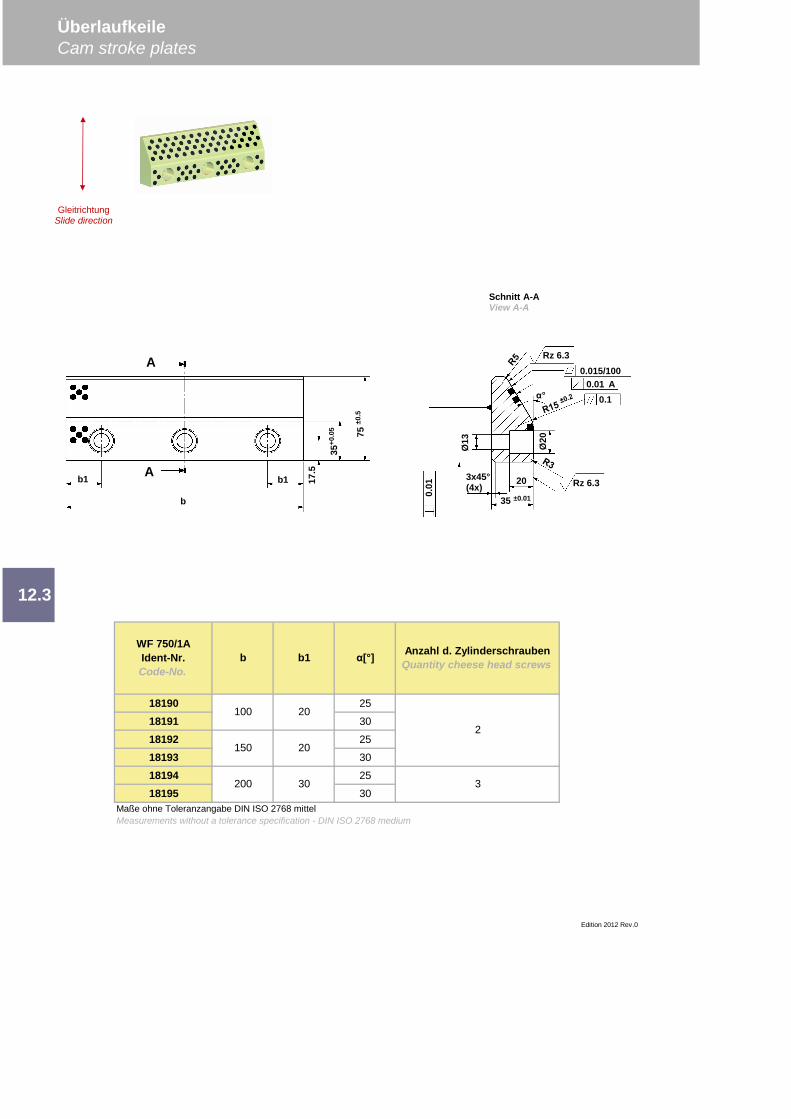
18190 25
18191 30
18192 25
18193 30
18194 25
18195 30
Anzahl d. ZylinderschraubenQuantity cheese head screws
Maße ohne Toleranzangabe DIN ISO 2768 mittelMeasurements without a tolerance specification - DIN ISO 2768 medium
2
3
100 20
150
200
20
30
Edition 2012 Rev.0
12.3
WF 750/1AIdent-Nr.Code-No.
b b1 [°]
ÜberlaufkeileCam stroke plates
Schnitt A-AView A-A
0.015/1000.01 A
0.01 Rz 6.33x45°
(4x)35 ±0.01
20
°
Rz 6.3
Ø13
0.1
Ø20
A
b1
b
b1 17.5
35+0
.05 75
±0.5
A
GleitrichtungSlide direction
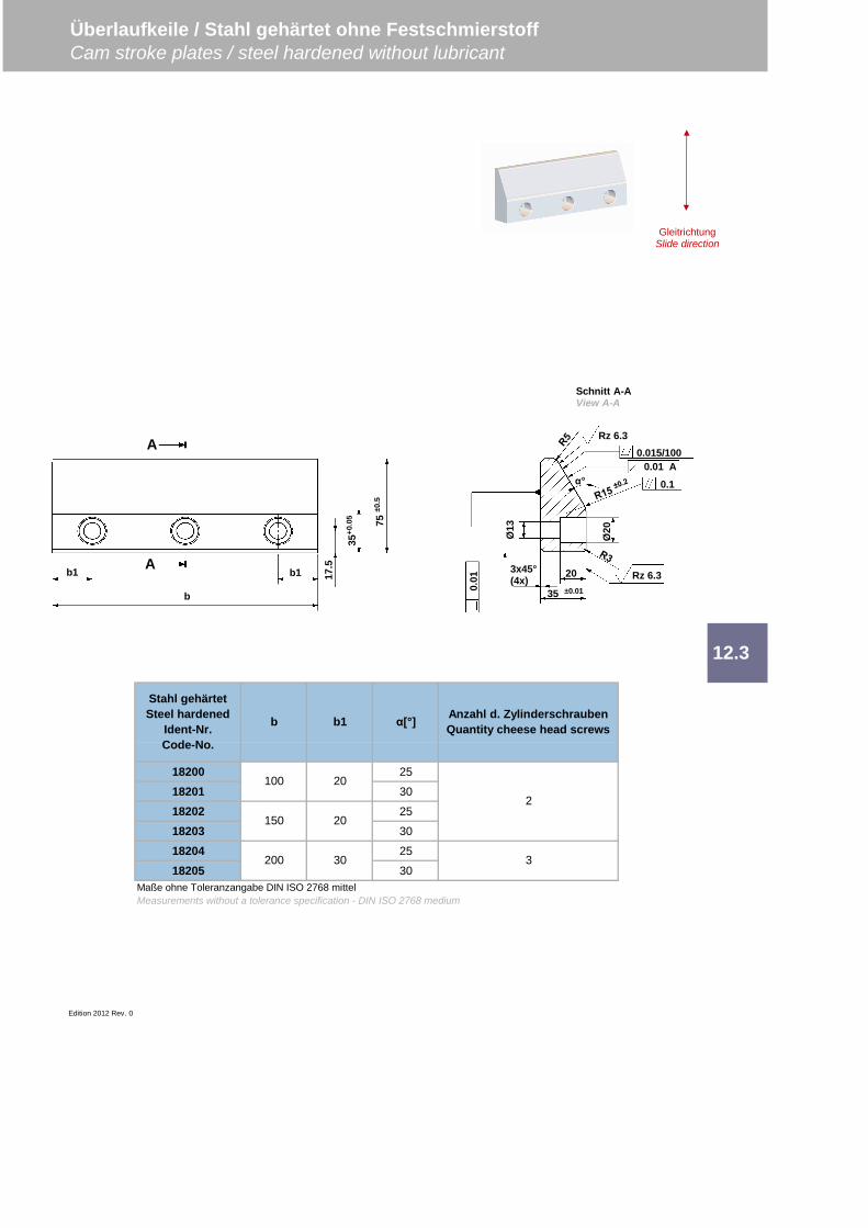
18200 25
18201 30
18202 25
18203 30
18204 25
18205 30
Edition 2012 Rev. 0
Maße ohne Toleranzangabe DIN ISO 2768 mittelMeasurements without a tolerance specification - DIN ISO 2768 medium
150 20
200 30
2
3
100 20
Stahl gehärtetSteel hardened
Ident-Nr.Code-No.
b b1 [°] Anzahl d. ZylinderschraubenQuantity cheese head screws
12.3
Überlaufkeile / Stahl gehärtet ohne FestschmierstoffCam stroke plates / steel hardened without lubricant
0.015/1000.01 A
0.01 Rz 6.33x45°
(4x)35 ±0.01
20
°
Rz 6.3
Ø13
0.1
Ø20
A
b1
b
b1 17.5
35+0
.05 75
±0.5
A
Schnitt A-AView A-A
GleitrichtungSlide direction
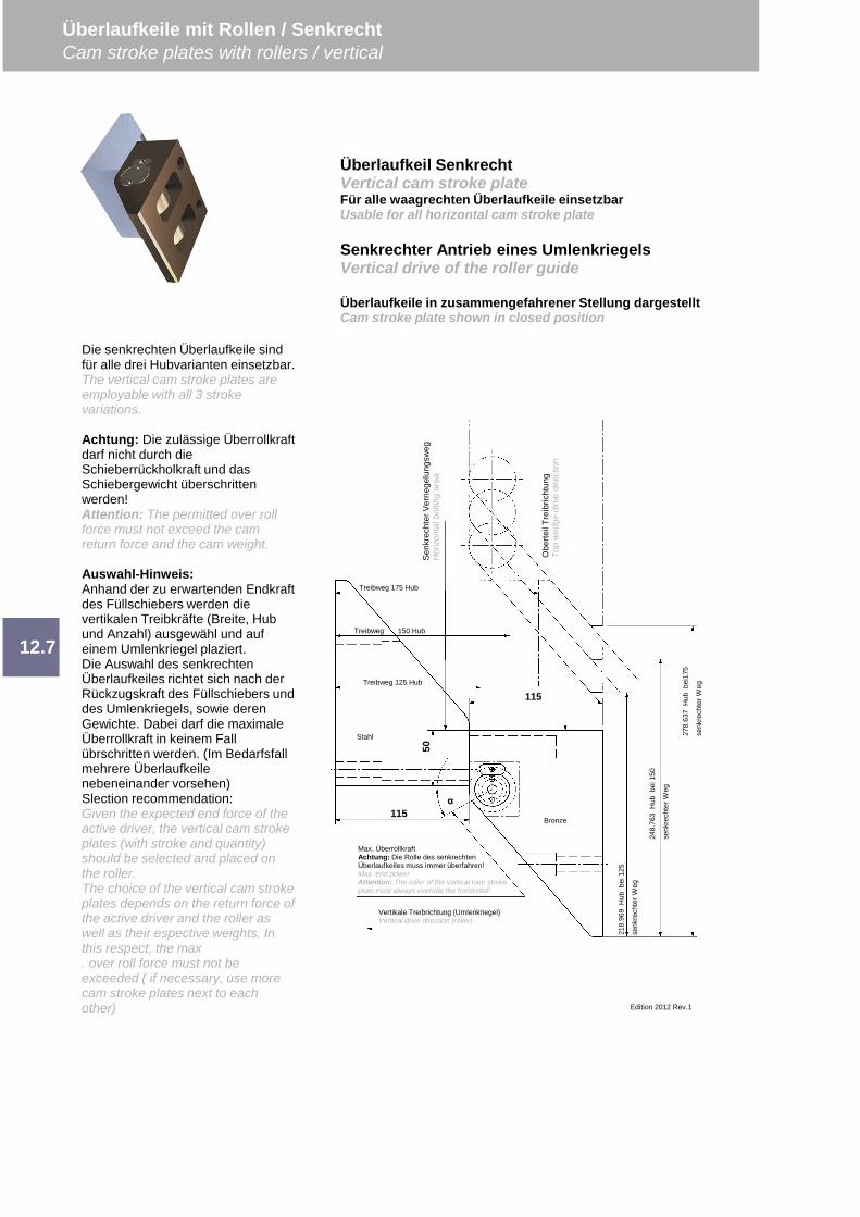
Edition 2012 Rev.1
12.7
Überlaufkeile mit Rollen / SenkrechtCam stroke plates with rollers / vertical
Die senkrechten Überlaufkeile sindfür alle drei Hubvarianten einsetzbar.The vertical cam stroke plates areemployable with all 3 strokevariations.
Achtung: Die zulässige Überrollkraftdarf nicht durch dieSchieberrückholkraft und dasSchiebergewicht überschrittenwerden!Attention: The permitted over rollforce must not exceed the camreturn force and the cam weight.
Auswahl-Hinweis:Anhand der zu erwartenden Endkraftdes Füllschiebers werden dievertikalen Treibkräfte (Breite, Hubund Anzahl) ausgewähl und aufeinem Umlenkriegel plaziert.Die Auswahl des senkrechtenÜberlaufkeiles richtet sich nach derRückzugskraft des Füllschiebers unddes Umlenkriegels, sowie derenGewichte. Dabei darf die maximaleÜberrollkraft in keinem Fallübrschritten werden. (Im Bedarfsfallmehrere Überlaufkeilenebeneinander vorsehen)Slection recommendation:Given the expected end force of theactive driver, the vertical cam strokeplates (with stroke and quantity)should be selected and placed onthe roller.The choice of the vertical cam strokeplates depends on the return force ofthe active driver and the roller aswell as their espective weights. Inthis respect, the max. over roll force must not beexceeded ( if necessary, use morecam stroke plates next to eachother)
Überlaufkeil SenkrechtVertical cam stroke plateFür alle waagrechten Überlaufkeile einsetzbarUsable for all horizontal cam stroke plate
Senkrechter Antrieb eines UmlenkriegelsVertical drive of the roller guide
Überlaufkeile in zusammengefahrener Stellung dargestelltCam stroke plate shown in closed position
218.
969
Hub
bei1
25
senk
rech
terW
eg
248.
763
Hub
bei1
50
senk
rech
terW
eg
278.
637
Hub
bei1
75
senk
rech
terW
eg
Obe
rteil
Trei
bric
htun
gTo
pw
edge
dirv
edi
rect
ion
Senk
rech
terV
errie
gelu
ngsw
egH
orizo
ntal
bolti
ngar
ea
115
50
115
Treibweg 175 Hub
Treibweg 150 Hub
Treibweg 125 Hub
Max. ÜberrollkraftAchtung: Die Rolle des senkrechtenÜberlaufkeiles muss immer überfahren!Max. end powerAttention: The roller of the vertical cam strokeplate must always override the horizontal!
Vertikale Treibrichtung (Umlenkriegel)Vertical drive direction (roller)
Stahl
Bronze
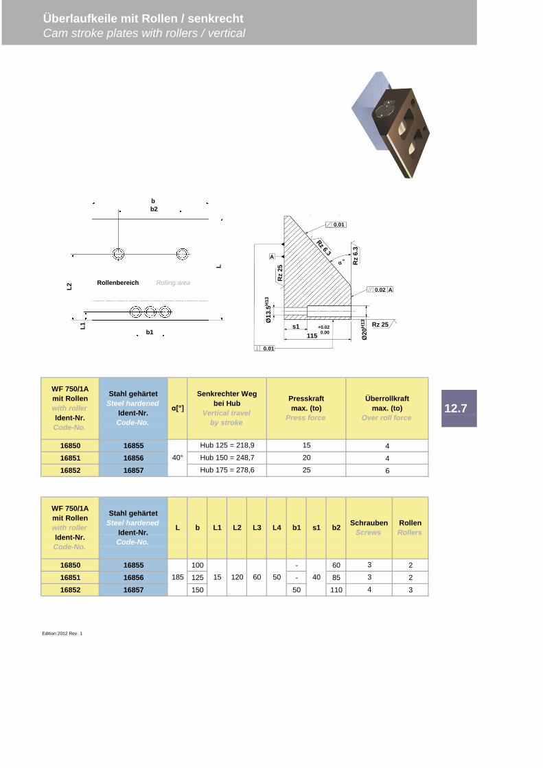
16850 1685516851 1685616852 16857
16850 16855 100 - 60 2
16851 16856 125 - 85 2
16852 16857 150 50 110 3
Edition 2012 Rev. 1
SchraubenScrews
RollenRollers
Überrollkraftmax. (to)
Over roll force
Presskraftmax. (to)
Press force
15
20
25
4
4
6
L1 L2 L3
185
3
3
4
15 120 60 50 40
b1 s1 b2L4
WF 750/1Amit Rollenwith rollerIdent-Nr.Code-No.
Stahl gehärtetSteel hardened
Ident-Nr.Code-No.
[°]
Senkrechter Wegbei Hub
Vertical travelby stroke
Hub 125 = 218,9
Hub 150 = 248,7
Hub 175 = 278,6
WF 750/1Amit Rollenwith rollerIdent-Nr.Code-No.
Stahl gehärtetSteel hardened
Ident-Nr.Code-No.
40°
L b
12.7
Überlaufkeile mit Rollen / senkrechtCam stroke plates with rollers / vertical
0.01
0.02
s1
Ø13
.5H
13
Ø20
H13
115+0.020.00
0.01
A
A
Rz
25
Rz
6.3
Rz 25
b2b
b1
L1
L2
L
Rollenbereich Rolling area
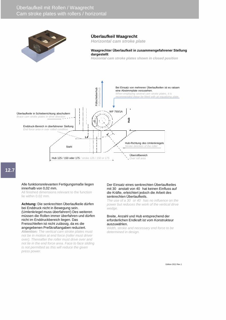
Überlaufkeil mit Rollen / WaagrechtCam stroke plates with rollers / horizontal
Edition 2012 Rev.1
12.7
Alle funktionsrelevanten Fertigungsmaße liegeninnerhalb von 0,02 mm.All finished dimensions relevant to the functionlie within 0.02 mm.
Achtung: Die senkrechten Überlaufkeile dürfenbei Enddruck nicht in Bewegung sein.(Umlenkriegel muss überfahren!) Des weiterenmüssen die Rollen immer überfahren und dürfennicht im Enddruckbereich liegen. DasFreisschleifen ist nicht zulässig, da es dieangegebenen Preßkraftangaben reduziert.Attention: The vertical cam stroke plates mustnot be in motion at end force (roller must driverover). Thereafter the roller must drive over andnot lie in the end force area. Face to face slidingis not permitted as this will reduce the givenpress power.
Überlaufkeil WaagrechtHorizontal cam stroke plate
Waagrechter Überlaufkeil in zusammengefahrener StellungdargestelltHoizontal cam stroke plates shown in closed position
Der Einsatz eines senkrechten Überlaufkeilesmit 30 anstatt von 40 hat keinen Einfluss aufdie Kräfte, erleichtert jedoch die Arbeit dessenkrechten Überlaufkeils.The use of a 30 or 40 has no inlfuence on thepower but reduces the work of the vertical dirvewedge.
Breite, Anzahl und Hub entsprechend dererforderlichen Endkraft ist vom Konstrukteurauszuwählen.Width, stroke and necessary end force to bedetermined in design.
Hub 125 / 150 oder 175 / stroke 125 / 150 or 175
Hub-Richtung des UmlenkriegelsStroke direction of the roller
ÜberrollbereichOver roll area
Enddruck-Bereich in überfahrener StellungEnd force area in over rolled condition
Überlaufkeile in Schieberrichtung abschulternBrace cam stroke plates in drive direction
L4
Hub
Stahl
WF 750/1A
Bei Einsatz von mehreren Überlaufkeilen ist es ratsameine Abstimmplate vorzusehen.When employing several cam stroke plates, it isrecommended these be fitted with an equalizing plate.
Fülls
chie
berh
ubFü
llsch
iebe
rhub
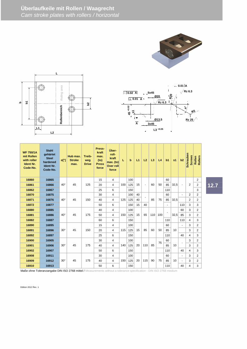
16860 16865 15 4 100 60 2
16861 16866 20 4 125 85 2
16862 16867 25 6 150 110 3
16871 16876 40 4 125 40 85 2 2
16872 16877 50 6 150 15 40 - 110 3 3
16880 16885 40 4 100 60 3 2
16881 16886 50 4 125 85 3 2
16882 16887 60 6 150 110 110 4 3
16890 16895 15 4 100 60 - 3 2
16891 16896 20 4 125 85 3 2
16892 16897 25 6 150 110 40 4 3
16900 16905 30 4 100 60 3 2
16901 16906 40 4 125 85 3 2
16902 16907 50 6 150 110 40 4 3
16908 16911 30 4 100 60 - 3 2
16909 16912 40 4 125 85 - 3 2
16910 16913 50 6 150 110 40 4 3
Maße ohne Toleranzangabe DIN ISO 2768 mittel / Measurements without a tolerance specification - DIN ISO 2768 medium
Edition 2012 Rev. 1
12.7
Press-kraftmax.(to)
Pressforce
Rol
len
Rol
lers
Über-roll-kraft
max. (to)Over roll
force
L b L1
30 4 100 40 60 - 2
WF 750/1Amit Rollenwith rollerIdent Nr.Code-No.
Stahlgehärtet
SteelhardenedIdent Nr.Code-No.
Hub max.Strokemax.
Treib-wegDrive
[°]
2
Überlaufkeile mit Rollen / WaagrechtCam stroke plates with rollers / horizontal
16870 16875
Schr
aube
nSc
rew
s
40°
40°
45 125
45 150
100 15 - 60 50 - 2
-85 32,5
32,5
L2 L3 L4 b1 s1 b2
30° 45 175 150
140
115
150
125 75
15 65 110 1001754540°
30° 45 150
30° 45 175
32,5-
15 85 60 50 10
-
20 115 90 75 10
20 110 8575
10
L1L2
L
b2b1b
Rol
lenb
erei
chR
ollin
gar
ea
0.02
0.01
0.01
A
A
A
5x45Ø20
Rz 6.3
Rz 6.3
Rz 25Ø13.53x45A
L3 +0.0545
+0.0
2
s1

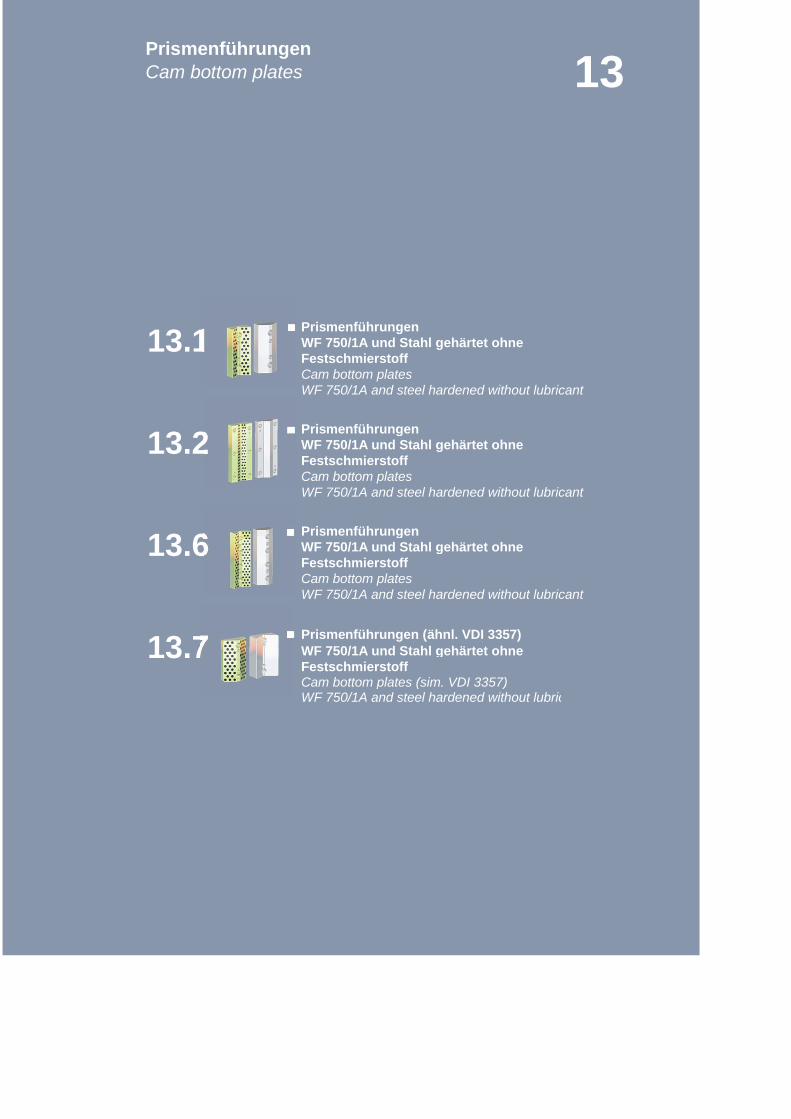
WF 750/1A und Stahl gehärtet ohneFestschmierstoffCam bottom platesWF 750/1A and steel hardened without lubricant
WF 750/1A und Stahl gehärtet ohneFestschmierstoffCam bottom platesWF 750/1A and steel hardened without lubricant
WF 750/1A und Stahl gehärtet ohneFestschmierstoffCam bottom platesWF 750/1A and steel hardened without lubricant
WF 750/1A und Stahl gehärtet ohneFestschmierstoffCam bottom plates (sim. VDI 3357)
13.7
13.1
Prismenführungen (ähnl. VDI 3357)
WF 750/1A and steel hardened without lubricant
PrismenführungenCam bottom plates 13
13.6
Prismenführungen
Prismenführungen
Prismenführungen
13.2
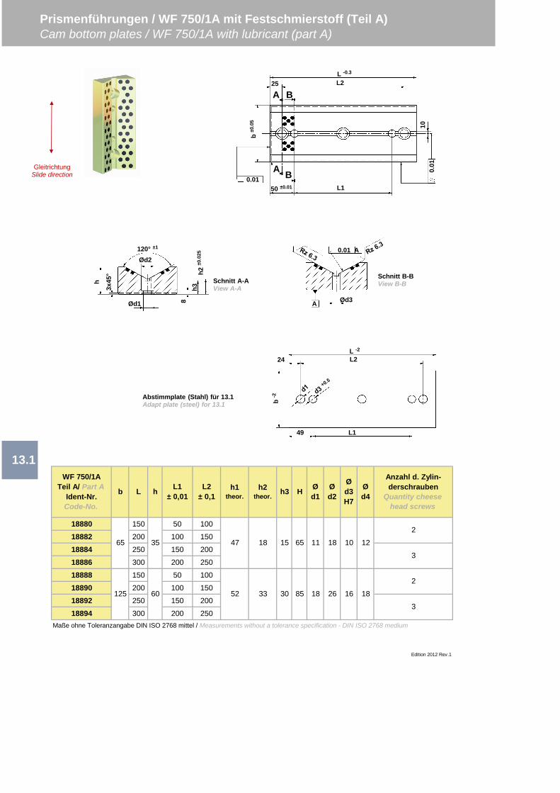
18880 150 50 100
18882 200 100 150
18884 250 150 200
18886 300 200 250
18888 150 50 100
18890 200 100 150
18892 250 150 200
18894 300 200 250Maße ohne Toleranzangabe DIN ISO 2768 mittel / Measurements without a tolerance specification - DIN ISO 2768 medium
Edition 2012 Rev.1
Prismenführungen / WF 750/1A mit Festschmierstoff (Teil A)Cam bottom plates / WF 750/1A with lubricant (part A)
L1± 0,01
WF 750/1ATeil A/ Part A
Ident-Nr.Code-No.
b L h
13.1
L2± 0,1
h1theor.
h2theor. h3
Anzahl d. Zylin-derschrauben
Quantity cheesehead screws
H
33
Ød1
Ød2
Ød3H7
Ød4
18 15 65 11
52
65
125
35
60
47
3
2
3
2
30 85 18 26 16 18
18 10 12
0.01 A
Ød3A
h2±0
.025
h38
Ød2120° ±1
Ød1
h
3x45
°
L -2
L224
49 L1
b-2
Schnitt A-AView A-A
Schnitt B-BView B-B
Abstimmplate (Stahl) für 13.1Adapt plate (steel) for 13.1
50 ±0.01 L1
L2L -0.3
10
b±0
.05
0.01
0.01
25
A
A B
BGleitrichtung
Slide direction
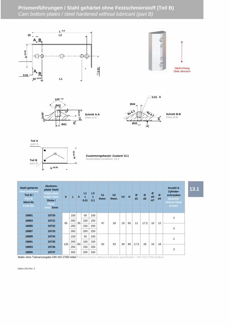
18881 19730 150 50 100
18883 19731 200 100 150
18885 19732 250 150 200
18887 19733 300 200 250
18889 19734 150 50 100
18891 19735 200 100 150
18893 19736 250 150 200
18895 19737 300 200 250
Maße ohne Toleranzangabe DIN ISO 2768 mittel / Measurements without a tolerance specification - DIN ISO 2768 medium
Edition 2012 Rev. 0
Prismenführungen / Stahl gehärtet ohne Festschmierstoff (Teil B)Cam bottom plates / steel hardened without lubricant (part B)
13.1Stahl gehärtetSteel hardened
Teil B /Part B
Ident-Nr.Code-No.
Abstimm-platte StahlAdapt-platebright steel
Dicke /Thick-
ness 5mm
b L h
125
35
60
47 18
52 33
Ød2
Ød3H7
Ød4
Anzahl d.Zylinder-
schraubenQuantity
cheese headscrews
65
L2±
0,1
h1theor.
h2theor. h3 H Ø
d1
L1±
0,01
26
15 65 11 17,5
30 85 17,5 16 18
2
3
2
3
10 12
50 ±0.01 L1
L2L -0.3
b±0
.05
0.01
0.01
25
A
A B
B
Teil Apart A
Teil Bpart B
b ±0.05
H±0
.05
Zusammengebauter Zustand 13.1Assembled condition 13.1
h1±0
.025
20
Ød2
120° ±1
Ød1
3x45
°
Schnitt A-AView A-A
3
0.01 A
Ød3A
20
Schnitt B-BView B-B
Ød4
GleitrichtungSlide direction
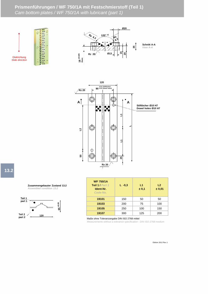
19101 150 50 50
19103 200 75 100
19105 250 100 150
19107 300 125 200
13.2
Prismenführungen / WF 750/1A mit Festschmierstoff (Teil 1)Cam bottom plates / WF 750/1A with lubricant (part 1)
Edition 2012 Rev.1
WF 750/1ATeil 1 / Part 1
Ident-Nr.Code-No.
L -0,3 L1 ± 0,1
L2 ± 0,01
Maße ohne Toleranzangabe DIN ISO 2768 mittelMeasurements without a tolerance specification - DIN ISO 2768 medium
Schnitt A-AView A-A
Ø20
120° ±1
15Ø13 20
35
18±0
.025
theo
r.
Rz 20
Teil 1part 1
Teil 2part 2 120
65±0
.05
120
90±0.01 (Stiftlöcher)±0.01 (dowel holes)
Rz 20
L2
L
L1L1
25
50
Rz 20
Stiftlöcher Ø10 H7Dowel holes Ø10 H7
A A
Zusammengebauter Zustand 13.2Assembled condition 13.2
GleitrichtungSlide direction
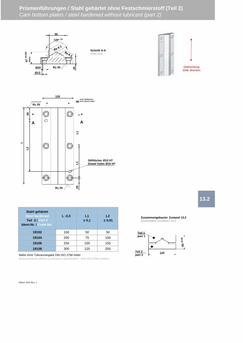
19102 150 50 50
19104 200 75 100
19106 250 100 150
19108 300 125 200
Edition 2012 Rev. 1
Prismenführungen / Stahl gehärtet ohne Festschmierstoff (Teil 2)Cam bottom plates / steel hardened without lubricant (part 2)
13.2
Stahl gehärtetSteel hardenedTeil 2 / Part 2
Ident-Nr. / Code-No.
L -0,3 L1± 0,1
L2 ± 0,01
Maße ohne Toleranzangabe DIN ISO 2768 mittelMeasurements without a tolerance specification - DIN ISO 2768 medium
Ø20
120° ±1
Ø13
Rz 20
55
47±0
.025
theo
r.
25
120
90±0.01 (Stiftlöcher)±0.01 (dowel holes)
Rz 20
L2
L
L1L1
25
50
Rz 20
Stiftlöcher Ø10 H7Dowel holes Ø10 H7
A A
Teil 1part 1
Teil 2part 2 120
65±0
.05
Zusammengebauter Zustand 13.2Assembled condition 13.2
Schnitt A-AView A-A
GleitrichtungSlide direction
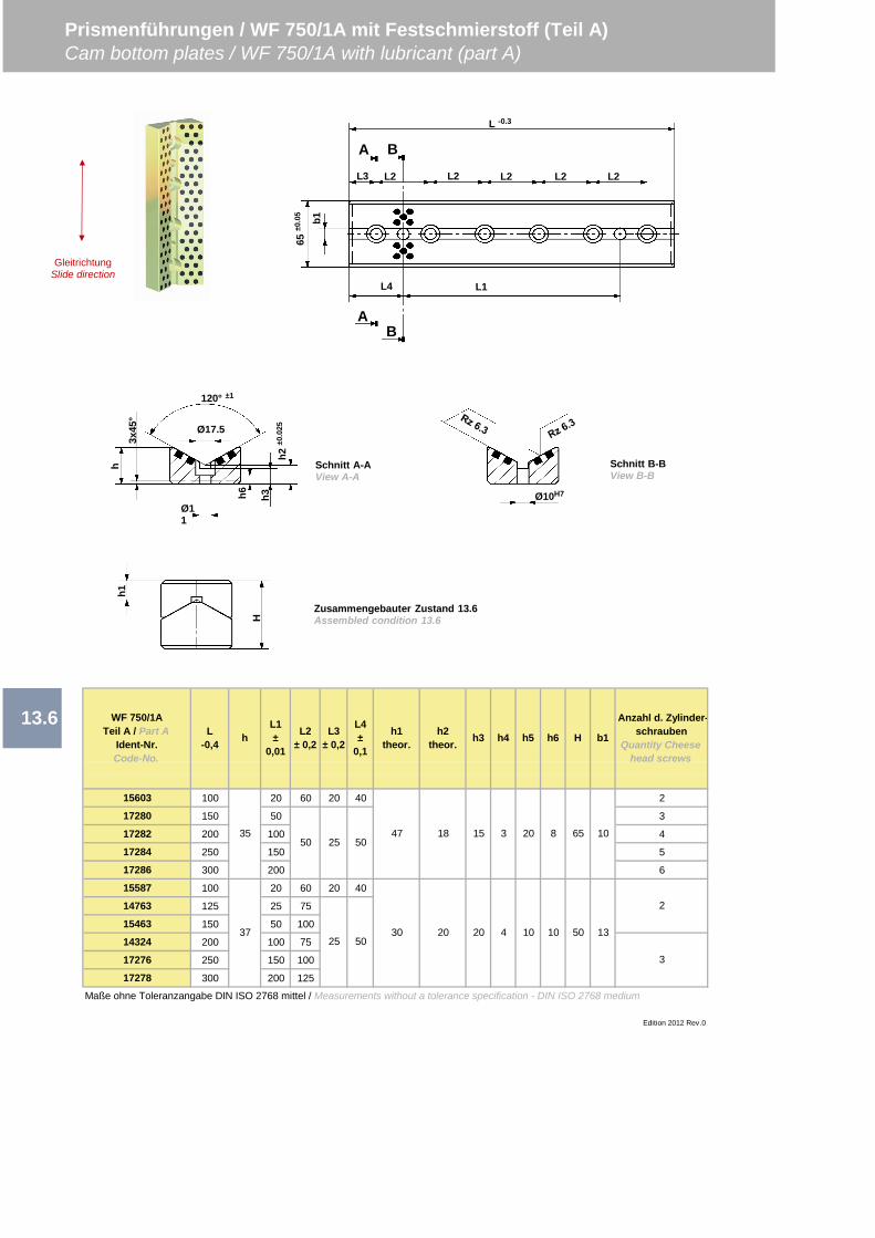
15603 100 20 60 20 40 2
17280 150 50 3
17282 200 100 4
17284 250 150 5
17286 300 200 6
15587 100 20 60 20 40
14763 125 25 75
15463 150 50 100
14324 200 100 75
17276 250 150 100
17278 300 200 125
Maße ohne Toleranzangabe DIN ISO 2768 mittel / Measurements without a tolerance specification - DIN ISO 2768 medium
13.6
Prismenführungen / WF 750/1A mit Festschmierstoff (Teil A)Cam bottom plates / WF 750/1A with lubricant (part A)
Anzahl d. Zylinder-schrauben
Quantity Cheesehead screws
Edition 2012 Rev.0
37
15 3 20
25 5030
2
3
1320 20 4 10 10
10
H b1
5035
25 5047 18
50
WF 750/1ATeil A / Part A
Ident-Nr.Code-No.
L-0,4 h
L1±
0,01
L2± 0,2
L3± 0,2
L4±
0,1
h1theor.
h2theor. h3 h4 h5 h6
8 65
b1
L -0.3
65±0
.05
L3
A
A B
B
h2±0
.025Ø17.5
120° ±1
Ø11
3x45
°h
L2 L2 L2 L2 L2
L1L4
h6 h3
Schnitt A-AView A-A
Ø10H7
Schnitt B-BView B-B
Zusammengebauter Zustand 13.6Assembled condition 13.6
h1
HGleitrichtung
Slide direction
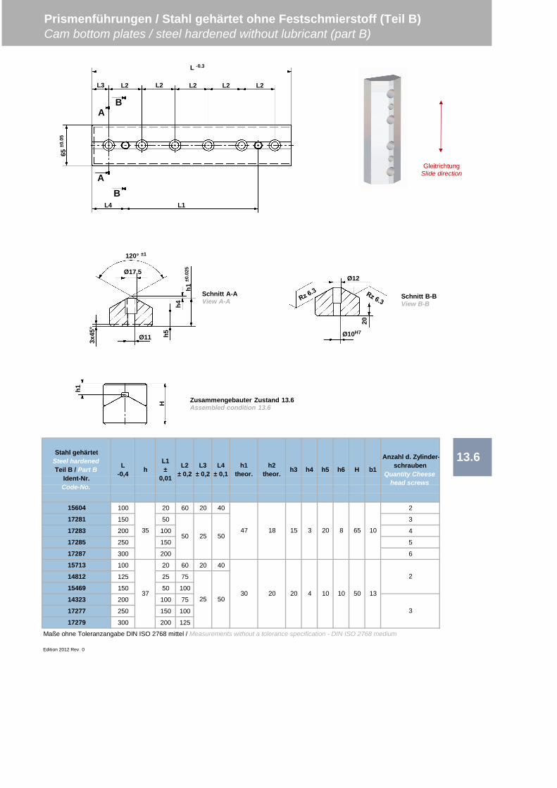
15604 100 20 60 20 40 2
17281 150 50 3
17283 200 100 4
17285 250 150 5
17287 300 200 6
15713 100 20 60 20 40
14812 125 25 75
15469 150 50 100
14323 200 100 75
17277 250 150 100
17279 300 200 125
Maße ohne Toleranzangabe DIN ISO 2768 mittel / Measurements without a tolerance specification - DIN ISO 2768 medium
Edition 2012 Rev. 0
Prismenführungen / Stahl gehärtet ohne Festschmierstoff (Teil B)Cam bottom plates / steel hardened without lubricant (part B)
13.6
3725 50
50 2535
5047 18 15 10
30 20 420 50
20
131010
h6 H
3 8 65
b1
Anzahl d. Zylinder-schrauben
Quantity Cheesehead screws
2
3
Stahl gehärtetSteel hardenedTeil B / Part B
Ident-Nr.Code-No.
L-0,4 h
L1±
0,01
L2± 0,2
L3± 0,2
L4± 0,1
h1theor.
h2theor. h3 h4 h5
h1±0
.025Ø17.5
120° ±1
Ø113x45
°
h4
h5
Schnitt A-AView A-A
Schnitt B-BView B-B
Zusammengebauter Zustand 13.6Assembled condition 13.6
h1
H
L -0.365
±0.0
5
L3
A
AB
B
L2 L2 L2 L2 L2
L1L4
Ø10H7
Ø12
20
GleitrichtungSlide direction
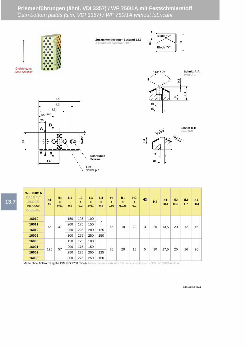
16010 150 125 100
16011 200 175 150
16012 250 225 200 125
16009 300 275 250 150
16000 150 125 100
16001 200 175 150
16002 250 225 200 125
16003 300 275 250 150Maße ohne Toleranzangabe DIN ISO 2768 mittel / Measurements without a tolerance specification - DIN ISO 2768 medium
Prismenführungen (ähnl. VDI 3357) / WF 750/1A mit FestschmierstoffCam bottom plates (sim. VDI 3357) / WF 750/1A without lubricant
Edition 2012 Rev.1
13.7
WF 750/1AMALE "V"
BLOCKIdent-Nr.Code-No.
L1-
0,2
b1h6
65
H1±
0,01
H2±
0,2
H3 H4 d1H13
L4±
0,2
L3±
0,01
L2±
0,2
H+
0,05
h1±
0,025
d2H13
d3H7
d4H13
65 18 20 3 20 13,5 20 12 16
125
-
-
47
57 17,5 26 16 2085 28 15 5 30
120° ± 0°1'
d1
H2
H3
H1
d2
H4
Schnitt A-AView A-A
d3
d4
Schnitt B-BView B-B
h1 H
Zusammengebauter Zustand 13.7Assembled condition 13.7
Block "U"
Block "V"
GleitrichtungSlide direction
b1
25
55 ±0.02
L2
L1
5x45
°
StiftDowel pin
SchraubenScrews
A
AB
B
L3
L4
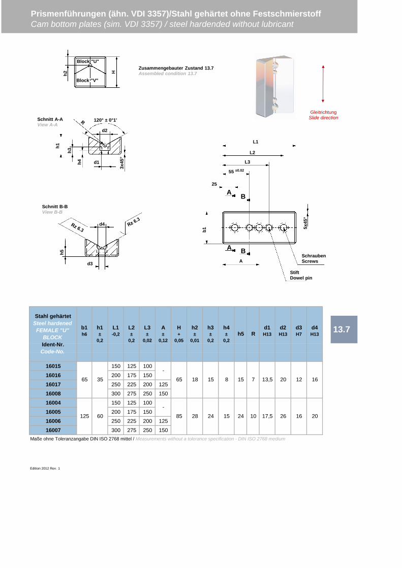
16015 150 125 100
16016 200 175 150
16017 250 225 200 125
16008 300 275 250 150
16004 150 125 100
16005 200 175 150
16006 250 225 200 125
16007 300 275 250 150Maße ohne Toleranzangabe DIN ISO 2768 mittel / Measurements without a tolerance specification - DIN ISO 2768 medium
Edition 2012 Rev. 1
Prismenführungen (ähn. VDI 3357)/Stahl gehärtet ohne FestschmierstoffCam bottom plates (sim. VDI 3357) / steel hardended without lubricant
13.7Stahl gehärtet
Steel hardenedFEMALE "U"
BLOCKIdent-Nr.Code-No.
L1-0,2
b1h6
h1±
0,2
A±
0,12
L3±
0,02
L2±
0,2
H+
0,05
h2±
0,01
h3±
0,2
h4±
0,2h5 R
d1H13
d2H13
d3H7
d4H13
65 35
125 60
-
-
65 18 15 8 15 7 13,5 20 12 16
85 28 24 15 24 10 17,5 26 16 20
Zusammengebauter Zustand 13.7Assembled condition 13.7h2 H
Block "U"
Block "V"
120° ± 0°1'
d1
3x45
°
h4
h3
d2
h1
Schnitt A-AView A-A
h5
d3
d4
Schnitt B-BView B-B
GleitrichtungSlide direction
25
b1
55 ±0.02
L1
5x45
°
StiftDowel pin
SchraubenScrews
A
A B
B
L2
L3
A

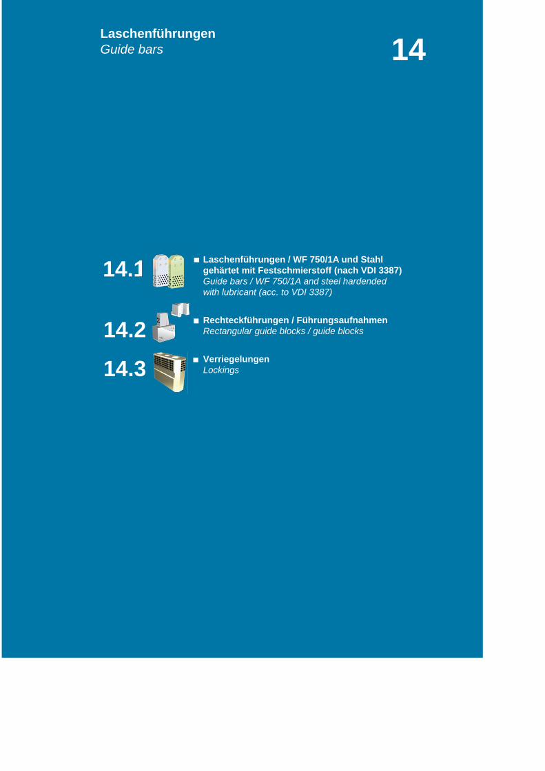
gehärtet mit Festschmierstoff (nach VDI 3387)Guide bars / WF 750/1A and steel hardendedwith lubricant (acc. to VDI 3387)
Rectangular guide blocks / guide blocks
Lockings
LaschenführungenGuide bars 14
14.3
Laschenführungen / WF 750/1A und Stahl
Rechteckführungen / Führungsaufnahmen
Verriegelungen
14.2
14.1
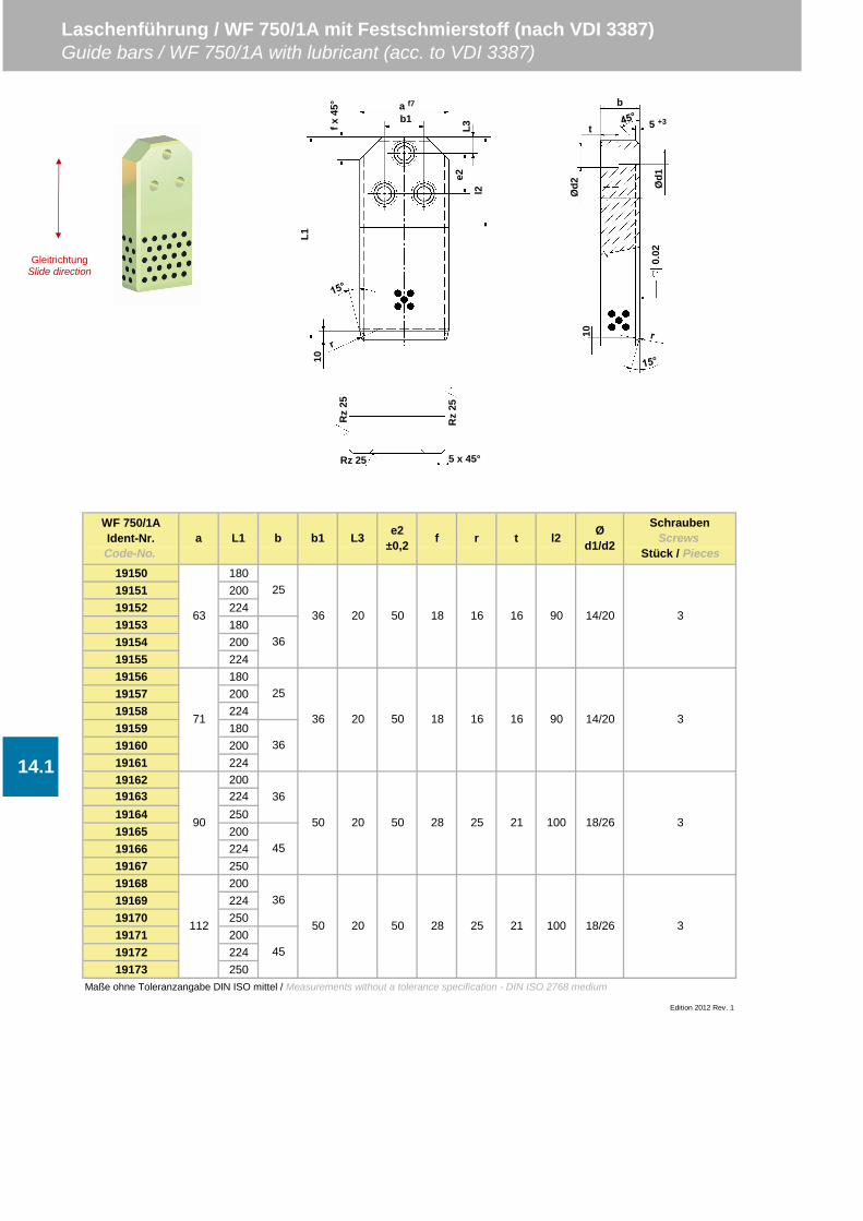
19150 18019151 20019152 22419153 18019154 20019155 22419156 18019157 20019158 22419159 18019160 20019161 22419162 200
19164 25019165 20019166 22419167 25019168 20019169 22419170 25019171 20019172 22419173 250
Maße ohne Toleranzangabe DIN ISO mittel / Measurements without a tolerance specification - DIN ISO 2768 medium
Edition 2012 Rev. 1
t
16
16
21
21
25
l2 Ød1/d2
SchraubenScrews
Stück / Piecesb1 r
16 90 14/20 3
16 90 14/20 3
36 20
WF 750/1AIdent-Nr.Code-No.
a L1 b
36
36
45
36
25
36
50 18
36 20 50 18
63
71
90
Laschenführung / WF 750/1A mit Festschmierstoff (nach VDI 3387)Guide bars / WF 750/1A with lubricant (acc. to VDI 3387)
L3 e2±0,2 f
50 28 25
14.119163
100 18/26 3
112
45
50 20 50 28 25 100 18/26 3
224
50 20
GleitrichtungSlide direction
b
t
Ød2 Ø
d10.
02
5 +3
10
a f7
b1
L3e2
fx45
°
L110
l2
Rz
25
Rz
25Rz 25 5 x 45°
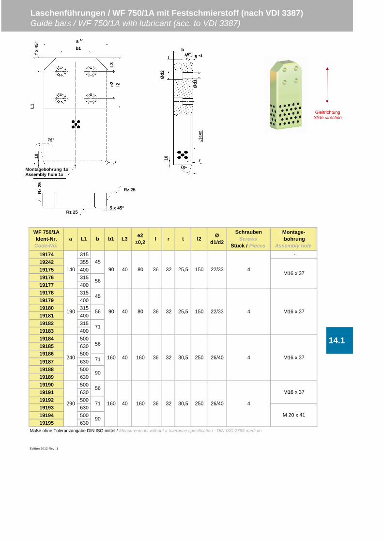
19174 315 -19242 35519175 40019176 31519177 40019178 31519179 40019180 31519181 40019182 31519183 40019184 50019185 630
19187 63019188 50019189 63019190 50019191 63019192 50019193 63019194 50019195 630
Maße ohne Toleranzangabe DIN ISO mittel / Measurements without a tolerance specification - DIN ISO 2768 medium
Edition 2012 Rev. 1
M16 x 37
160 40290
150 22/33
40 160 36 30,5 250 26/40
56
71
56
71
Ød1/d2
SchraubenScrews
Stück / Pieces
40 80 36 25,5
r
32
14.1
Laschenführungen / WF 750/1A mit Festschmierstoff (nach VDI 3387)Guide bars / WF 750/1A with lubricant (acc. to VDI 3387)
240 16050019186
Montage- bohrung
Assembly hole
WF 750/1AIdent-Nr.Code-No.
a L1 b b1 L3 e2±0,2 f t l2
M16 x 37
190 90 40 80 36 25,5 150 22/33 4 M16 x 37
14045
90
56
45
160 3671
90
4
56
90
4
32
32
32
M16 x 37
M 20 x 41
30,5 250 26/40 4
GleitrichtungSlide direction
b
t
Ød2
Ød1
0.02
5 +3
10
Rz
25
Rz 25
Rz 255 x 45°
Montagebohrung 1xAssembly hole 1x
a f7
b1
L3e2
fx45
°L1
10
l2
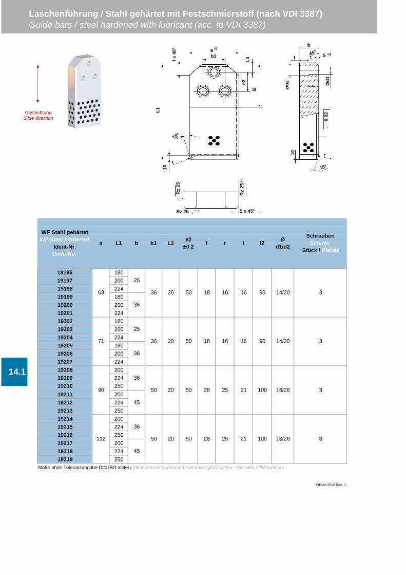
19196 18019197 20019198 22419199 18019200 20019201 22419202 18019203 20019204 22419205 18019206 20019207 22419208 20019209 224
19211 20019212 22419213 25019214 20019215 22419216 25019217 20019218 22419219 250
Maße ohne Toleranzangabe DIN ISO mittel / Measurements without a tolerance specification - DIN ISO 2768 medium
Edition 2012 Rev. 1
t
16
16
21
21
Laschenführung / Stahl gehärtet mit Festschmierstoff (nach VDI 3387)Guide bars / steel hardened with lubricant (acc. to VDI 3387)
l2 Ød1/d2
SchraubenScrews
Stück / Pieces
14.1
18 16
25 100 18/26 3
36
36 20 50 90 14/20
20 50 28 25
WF Stahl gehärtetWF Steel hardened
Ident-Nr.Code-No.
a L1
112
36
36
19210 250
63
71
90
25
3
45
50 20 50 28
b
100 18/26 3
25
36
36 20 50 18 16 14/2090 3
50
45
b1 L3 e2±0,2 f r
Rz
25
Rz
25
Rz 25 5 x 45°
b
t
Ød2 Ø
d10.
02
5 +3
10
GleitrichtungSlide direction
a f7
b1
L3e2
fx45
°
L110
l2
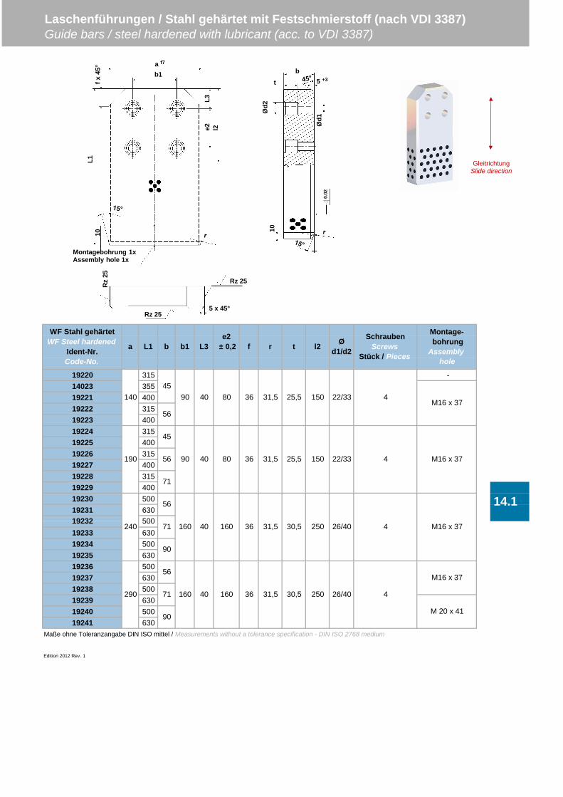
19220 315 -14023 35519221 40019222 31519223 40019224 31519225 40019226 31519227 40019228 31519229 40019230 50019231 630
19233 63019234 50019235 63019236 50019237 63019238 50019239 63019240 50019241 630
Maße ohne Toleranzangabe DIN ISO mittel / Measurements without a tolerance specification - DIN ISO 2768 medium
Edition 2012 Rev. 1
Laschenführungen / Stahl gehärtet mit Festschmierstoff (nach VDI 3387)Guide bars / steel hardened with lubricant (acc. to VDI 3387)
480 22/33M16 x 37
WF Stahl gehärtetWF Steel hardened
Ident-Nr.Code-No.
L1a b b1 Ød1/d2
SchraubenScrews
Stück / Pieces
14.1
36 31,5 30,5
36
M16 x 37
26/40 4 M16 x 37
26/40 4
M 20 x 41
31,5 30,5
250
250
19232
14045
90 40
56
45
56
71
56
71500
190 90 40 80 36 31,5 25,5 22/33150 4 M16 x 37
36 31,5 25,5 150
290
240 160 40 160
160 40 16071
90
90
56
Montage- bohrungAssembly
hole
L3e2
± 0,2 f r t l2
b
t
Ød2
Ød1
0.02
5 +3
10
GleitrichtungSlide direction
Montagebohrung 1xAssembly hole 1x
a f7
b1
L3e2
fx45
°L1
10
l2
Rz
25
Rz 25
Rz 255 x 45°
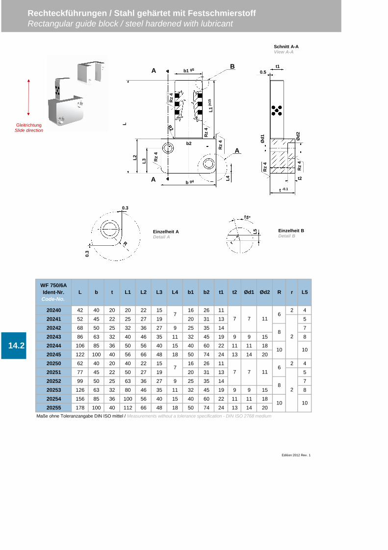
20240 42 40 20 20 22 15 16 26 11 2 4
20241 52 45 22 25 27 19 20 31 13 5
20242 68 50 25 32 36 27 9 25 35 14 7
20243 86 63 32 40 46 35 11 32 45 19 9 9 15 8
20244 106 85 36 50 56 40 15 40 60 22 11 11 18
20245 122 100 40 56 66 48 18 50 74 24 13 14 20
20250 62 40 20 40 22 15 16 26 11 2 4
20251 77 45 22 50 27 19 20 31 13 5
20252 99 50 25 63 36 27 9 25 35 14 7
20253 126 63 32 80 46 35 11 32 45 19 9 9 15 8
20254 156 85 36 100 56 40 15 40 60 22 11 11 18
20255 178 100 40 112 66 48 18 50 74 24 13 14 20Maße ohne Toleranzangabe DIN ISO mittel / Measurements without a tolerance specification - DIN ISO 2768 medium
Edition 2012 Rev. 1
Rechteckführungen / Stahl gehärtet mit FestschmierstoffRectangular guide block / steel hardened with lubricant
WF 750/6AIdent-Nr.Code-No.
L3
14.2
L b t L1 L2
7
L4 b1 b2 t1 Ød2 R r L5
7
t2 Ød1
1010
7 7 11
7 7 11
2
28
6
10
8
6
10
b2
b g4 L4
L
L2
L3 Rz
4
Rz
4
Rz
4
Rz
4
b1 g5
L1js
15
A
A B
A
t -0.1
t2
Rz
4
Rz
4Ø
d1 Ød2
0.5t1
L5
0.3
0.3
Schnitt A-AView A-A
Einzelheit ADetail A
Einzelheit BDetail B
GleitrichtungSlide direction
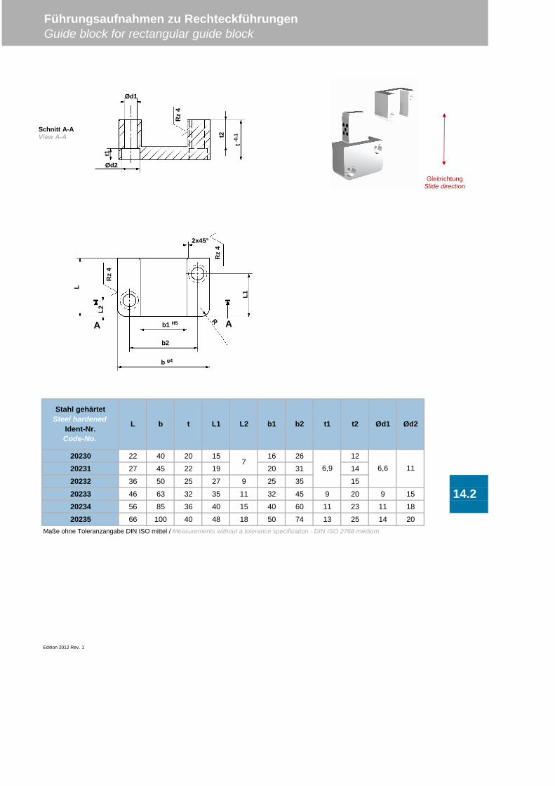
20230 22 40 20 15 16 26 12
20231 27 45 22 19 20 31 14
20232 36 50 25 27 9 25 35 15
20233 46 63 32 35 11 32 45 9 20 9 15
20234 56 85 36 40 15 40 60 11 23 11 18
20235 66 100 40 48 18 50 74 13 25 14 20Maße ohne Toleranzangabe DIN ISO mittel / Measurements without a tolerance specification - DIN ISO 2768 medium
Edition 2012 Rev. 1
Führungsaufnahmen zu RechteckführungenGuide block for rectangular guide block
14.2
Stahl gehärtetSteel hardened
Ident-Nr.Code-No.
L b t L1 Ød2
6,9 6,6 11
L2 b1 b2 t1 t2 Ød1
7
GleitrichtungSlide direction
Rz
4L2
L
L1
Rz
4
2x45°
b2
b1 H5
b g4
AA
t-0.1
Ød2
Ød1
t2
t1
Rz
4
Schnitt A-AView A-A
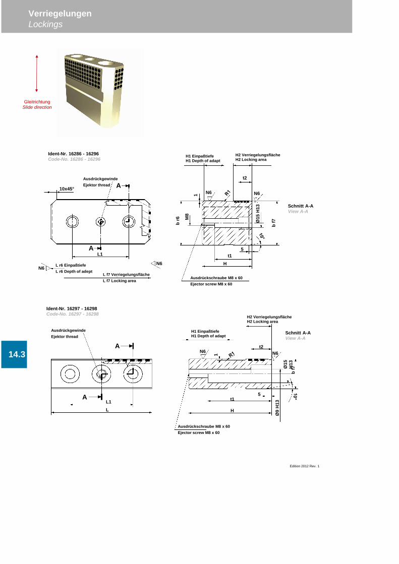
Edition 2012 Rev. 1
VerriegelungenLockings
14.3
H1 EinpaßtiefeH1 Depth of adapt
H2 VerriegelungsflächeH2 Locking area
t2N6 N6
H
bf7Ø
15H
13
5t1
Ausdrückschraube M8 x 60Ejector screw M8 x 60
Ø9
H13
1
Schnitt A-AView A-A
AusdrückgewindeEjektor thread
L1L
A
A
Schnitt A-AView A-A
Ident-Nr. 16297 - 16298Code-No. 16297 - 16298
Ident-Nr. 16286 - 16296Code-No. 16286 - 16296
t2
H1 EinpaßtiefeH1 Depth of adapt
H2 VerriegelungsflächeH2 Locking area
N6 N61
br6
bf7Ø
15H
135
t1
Ausdrückschraube M8 x 60Ejector screw M8 x 60
M8
H
GleitrichtungSlide direction
10x45°
L1
L f7 VerriegelungsflächeL f7 Locking area
L r6 EinpaßtiefeL r6 Depth of adept
AusdrückgewindeEjektor thread
N6N6
A
A
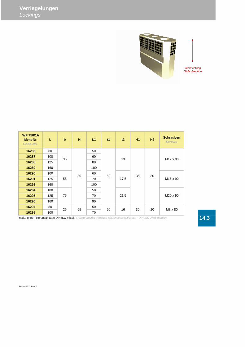
16286 80 50
16287 100 60
16288 125 80
16289 160 100
16290 100 60
16291 125 70
16293 160 100
16294 100 50
16295 125 70
16296 160 90
16297 80 50
16298 100 70Maße ohne Toleranzangabe DIN ISO mittel / Measurements without a tolerance specification - DIN ISO 2768 medium
Edition 2012 Rev. 1
VerriegelungenLockings
14.3
WF 750/1AIdent-Nr.Code-No.
L b H L1 t2 H1 H2 SchraubenScrews
35 13 M12 x 90
t1
25 65 50
556080
17,5 M16 x 9035 30
75 M20 x 90
M8 x 80
21,5
16 30 20
GleitrichtungSlide direction

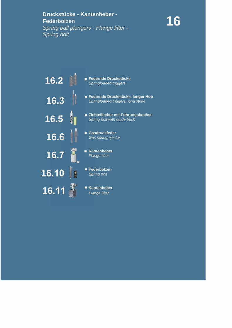
Federnde Druckstücke
Springloaded triggers, long strike
Spring bolt with guide bush
Gas spring ejector
Flange lifter
Spring boltFederbolzen
16.3
16.6
Federnde Druckstücke, langer Hub
Kantenheber
16.10
16.5 Ziehteilheber mit Führungsbüchse
Gasdruckfeder
Kantenheber
16.11
16.7
Flange lifter
Druckstücke - Kantenheber -FederbolzenSpring ball plungers - Flange lifter -Spring bolt
16.2
16
Springloaded triggers

Edition 2012 Rev.0
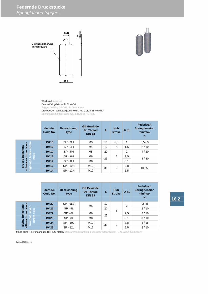
19415 SP - 3H M3 10 1,5 1 0,5 / 3
19416 SP - 4H M4 12 2 1,6 2 / 10
19410 SP - 5H M5 20 2 4 / 20
19411 SP - 6H M6 2,5
19412 SP - 8H M8 3,1
19413 SP - 10H M10 3,8
19414 SP - 12H M12 5,5
19420 SP - 5LS 13 2 / 8
19421 SP - 5L 20 2 / 10
19422 SP - 6L M6 2,5 3 / 10
19423 SP - 8L M8 3,1 3 / 10
19424 SP - 10L M10 3,8 3 / 15
19425 SP - 12L M12 5,5 2 / 10Maße ohne Toleranzangabe DIN ISO mittel / Measurements without a tolerance specification - DIN ISO 2768 medium
Edition 2012 Rev. 0
Federnde DruckstückeSpringloaded triggers
16.2
klei
neB
elas
tung
silb
er-c
hrom
.Nas
elo
wlo
adsi
lver
-ch
rom
nose
Ident-Nr.Code No.
BezeichnungType
Ød GewindeØd Thread
DIN 13L
30
gros
seB
elas
tung
schw
arz-
chro
m.N
ase
high
load
blac
k-ch
rom
nose
Ident-Nr.Code No.
BezeichnungType
Ød GewindeØd Thread
DIN 13L
30
25
5
Werkstoff: Material:Druckstückgehäuse 34 CrMoS4Trigger housing 34 CrMoS4 black cromDruckbolzen Werkzeugstahl Wkst.-Nr. 1.1625 36-40 HRCSpringloaded trigger Wks.-No. 1.1625 36-40 HRC
5
8 / 30
M5
3
25
2
10 / 50
HubStroke Ø d1
FederkraftSpring tension
min/maxN
Ø d1
FederkraftSpring tension
min/maxN
HubStroke
3
Ø d1
Hub
Stro
keL
Ø d
GewindesicherungThread guard
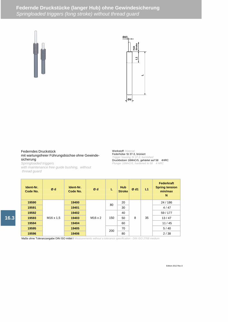
19590 19400 20 24 / 186
19591 19401 30 4 / 47
19592 19402 40 59 / 177
19593 19403 50 13 / 47
19594 19404 60 11 / 45
19595 19405 70 5 / 40
19596 19406 80 2 / 38Maße ohne Toleranzangabe DIN ISO mittel / Measurements without a tolerance specification - DIN ISO 2768 medium
Ident-Nr.Code No. Ø d Ident-Nr.
Code No.
Federnde Druckstücke (langer Hub) ohne GewindesicherungSpringloaded triggers (long stroke) without thread guard
16.3
Edition 2012 Rev.0
FederkraftSpring tension
min/maxN
8
HubStroke
M16 x 1,5
L
35
Ø d1 L1Ø d
M16 x 2
80
150
200
Federndes Druckstückmit wartungsfreier Führungsbüchse ohne Gewinde-sicherungSpringloaded triggerswith maintenance free guide bushing, withoutthread guard
Werkstoff: Material:Federhülse St 37-3, brüniertTrigger housing St 37-3, burnishedDruckbolzen 16MnCr5, gehärtet auf 58 4HRCPlunger 16MnCr5, hardened to 58 4 HRC
Ød
L
L1H
ubSt
roke
Ød1
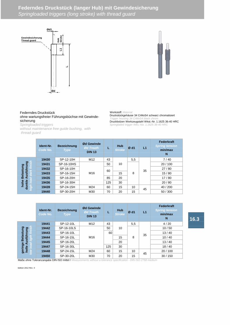
19430 SP-12-10H M12 43 5,5 7 / 4019431 SP-16-10HS 50 20 / 10019432 SP-16-10H 27 / 8019433 SP-16-15H 15 15 / 8019435 SP-16-20H 85 20 17 / 8019436 SP-16-30H 125 30 20 / 8019439 SP-24-15H M24 60 15 10 40 / 20019440 SP-30-20H M30 70 20 15 50 / 300
19441 SP-12-10L M12 43 5,5 4 / 20
19443 SP-16-10L 60 13 / 4019444 SP-16-15L 15 10 / 4019445 SP-16-20L 20 13 / 4019447 SP-16-30L 125 30 18 / 4019448 SP-24-15L M24 60 15 10 20 / 10019450 SP-30-20L M30 70 20 15 30 / 150
Maße ohne Toleranzangabe DIN ISO mittel / Measurements without a tolerance specification - DIN ISO 2768 medium
Edition 2012 Rev. 0
FederkraftSpring tension
min/maxN
10
835
10
835
45
HubStroke Ø d1 L1
16.3
Federndes Druckstück (langer Hub) mit GewindesicherungSpringloaded triggers (long stroke) with thread guard
gerin
geB
elas
tung
helle
Aus
führ
ung
low
load
ligth
finis
h 19442 SP-16-10LS
M16
50
45
10 / 50
Ident-Nr.Code No.
BezeichnungType
Ød GewindeØd Treath
DIN 13L Hub
Stroke Ø d1 L1
FederkraftSpring tension
min/maxN
hohe
Bel
astu
ngdu
nkle
Aus
führ
ung
high
load
dark
finis
h
Ident-Nr.Code No.
BezeichnungType
Ød GewindeØd Treath
DIN 13L
M1660
Federndes Druckstückohne wartungsfreier Führungsbüchse mit Gewinde-sicherungSpringloaded triggerswithout maintenance free guide bushing, withthread guard
Werkstoff: Material:Druckstückgehäuse 34 CrMoS4 schwarz chromatisiertTrigger housing 34 CrMoS4 black chromDruckbolzen Werkzeugstahl Wkst.-Nr. 1.1625 36-40 HRCSpringladed trigger Wks.-No. 1.1625 36-40 HRC
Ød
L
L1H
ubSt
rokeGewindesicherung
Thread guard
Ød1
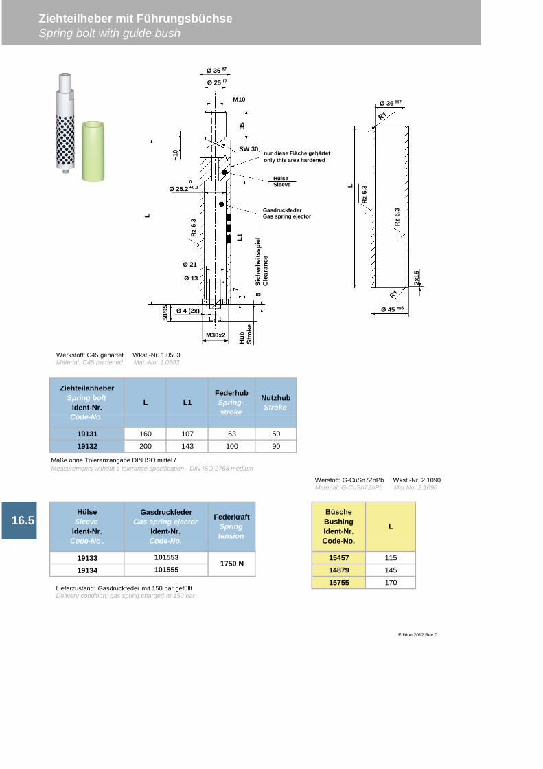
19131 160 107 63 50
19132 200 143 100 90
19133 15457 115
19134 14879 145
15755 170
NutzhubStroke
16.5
ZiehteilanheberSpring bolt
Ident-Nr.Code-No.
HülseSleeve
Ident-Nr.Code-No .
L L1FederhubSpring-stroke
Maße ohne Toleranzangabe DIN ISO mittel /Measurements without a tolerance specification - DIN ISO 2768 medium
FederkraftSpringtension
1750 N
Edition 2012 Rev.0
GasdruckfederGas spring ejector
Ident-Nr.Code-No.
101553101555
BüscheBushingIdent-Nr.Code-No.
L
Ziehteilheber mit FührungsbüchseSpring bolt with guide bush
Werstoff: G-CuSn7ZnPb Wkst.-Nr. 2.1090Material: G-CuSn7ZnPb Mat.No. 2.1090
Lieferzustand: Gasdruckfeder mit 150 bar gefülltDelivery condition: gas spring charged to 150 bar
L
Rz
6.3
Rz
6.3
2x15
Ø 45 m6
Ø 36 H7
Ø 36 f7
Ø 25 f7
M10
Ø 25.20+0.1
Ø 21
Ø 13
Ø 4 (2x)
M30x2
58/9
5
Hub
Stro
ke
7
5
~10 SW 30
35
Rz
6.3L
L1
HülseSleeve
GasdruckfederGas spring ejector
nur diese Fläche gehärtetonly this area hardened
Sich
erhe
itssp
iel
Cle
aran
ce
Werkstoff: C45 gehärtet Wkst.-Nr. 1.0503Material: C45 hardened Mat.-No. 1.0503
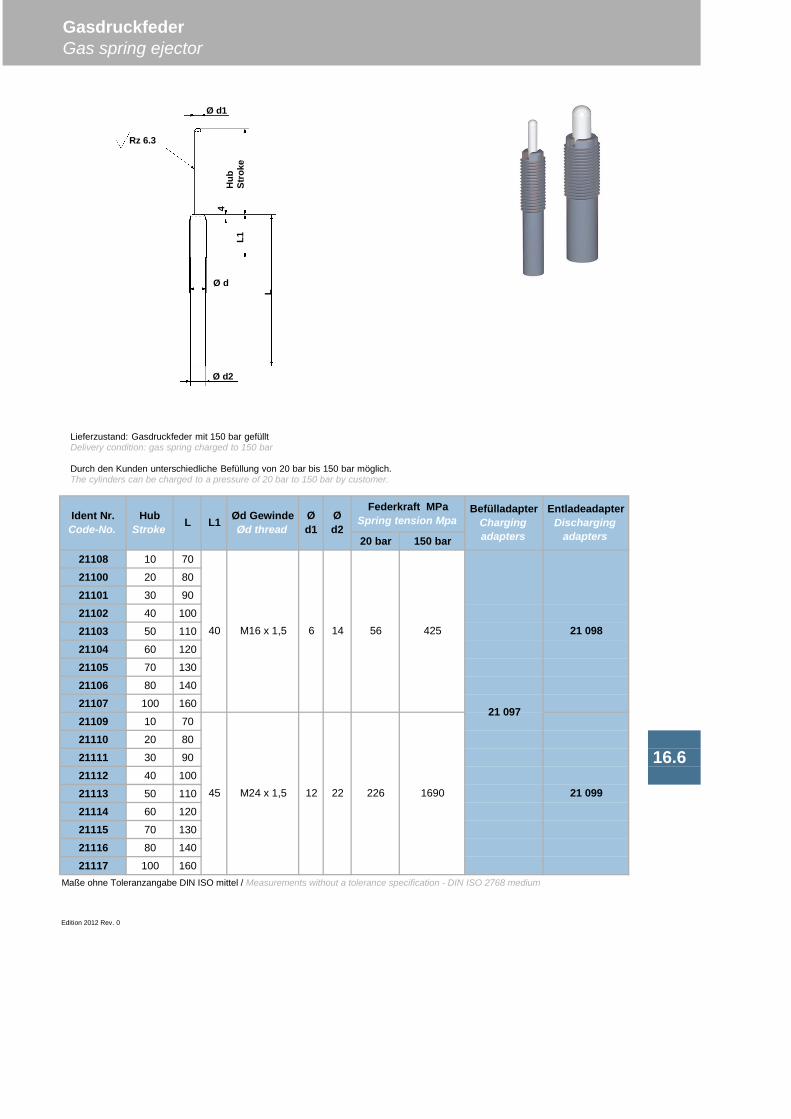
20 bar 150 bar21108 10 70
21100 20 80
21101 30 90
21102 40 100
21103 50 110
21104 60 120
21105 70 130
21106 80 140
21107 100 160
21109 10 70
21110 20 80
21111 30 90
21112 40 100
21113 50 110
21114 60 120
21115 70 130
21116 80 140
21117 100 160Maße ohne Toleranzangabe DIN ISO mittel / Measurements without a tolerance specification - DIN ISO 2768 medium
Edition 2012 Rev. 0
GasdruckfederGas spring ejector
Ød1
16.6
Ød2
Federkraft MPaSpring tension Mpa
BefülladapterChargingadapters
EntladeadapterDischarging
adapters
21 097
21 098
21 0991690
425
Ident Nr.Code-No.
HubStroke L L1 Ød Gewinde
Ød thread
M16 x 1,540 6 14 56
45 M24 x 1,5 12 22 226
Lieferzustand: Gasdruckfeder mit 150 bar gefülltDelivery condition: gas spring charged to 150 bar
Durch den Kunden unterschiedliche Befüllung von 20 bar bis 150 bar möglich.The cylinders can be charged to a pressure of 20 bar to 150 bar by customer.
Ø d2
Ø d
Ø d1
L1
L
4H
ubSt
roke
Rz 6.3
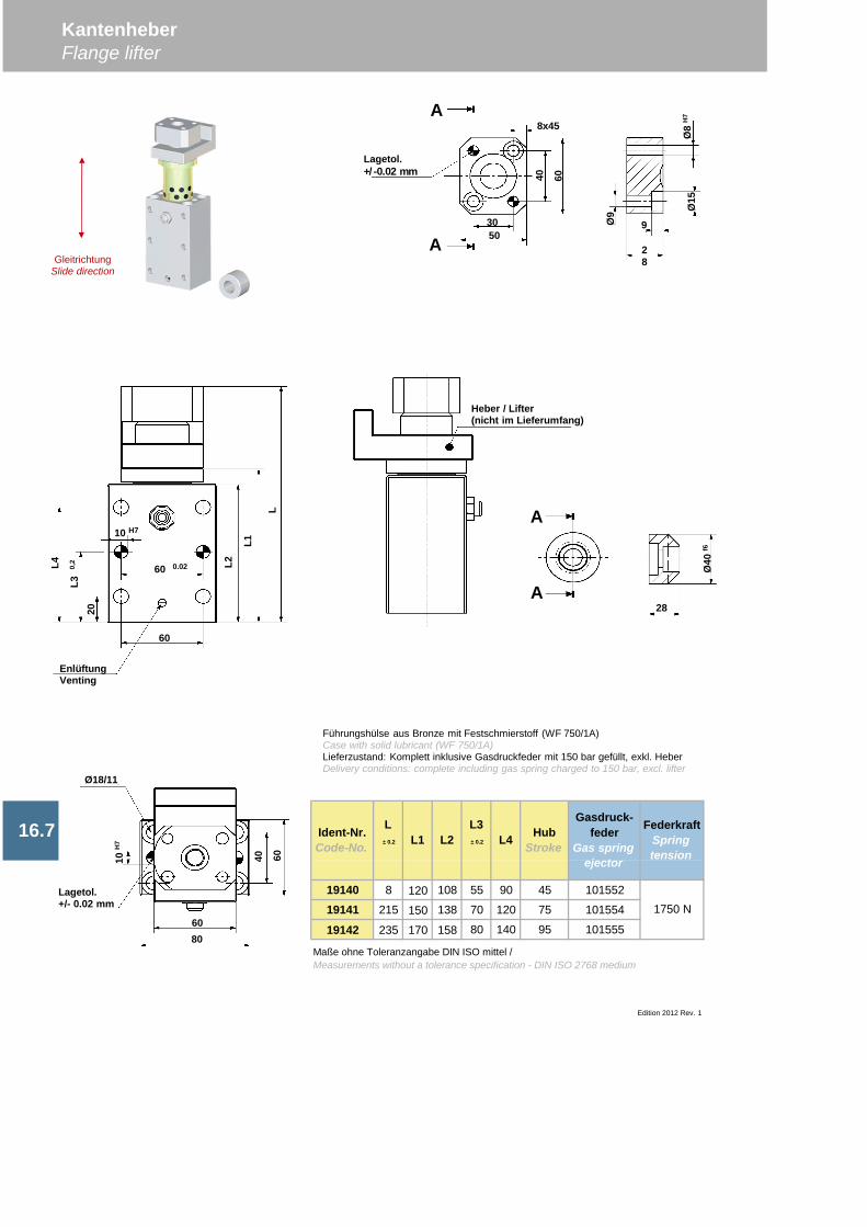
19140 8 120 108 55 90 45 101552
19141 215 150 138 70 120 75 101554
19142 235 170 158 80 140 95 101555
KantenheberFlange lifter
Edition 2012 Rev. 1
Ident-Nr.Code-No.
L ± 0.2 L1 L2
L3 ± 0.2 L4 Hub
Stroke16.7
Gasdruck-feder
Gas springejector
FederkraftSpringtension
1750 N
Maße ohne Toleranzangabe DIN ISO mittel /Measurements without a tolerance specification - DIN ISO 2768 medium
10 H7
60 0.02
Führungshülse aus Bronze mit Festschmierstoff (WF 750/1A)Case with solid lubricant (WF 750/1A)Lieferzustand: Komplett inklusive Gasdruckfeder mit 150 bar gefüllt, exkl. HeberDelivery conditions: complete including gas spring charged to 150 bar, excl. lifter
8x45
40 60
3050
Ø8
H7
Ø15
28
9Ø9
28
Ø40
f6
Heber / Lifter(nicht im Lieferumfang)
60
L4
20
L2
L1
L
EnlüftungVenting
10H
7
Ø18/11
40 60
6080
Lagetol.+/- 0.02 mm
A
A
A
AGleitrichtung
Slide direction
L30,
2
Lagetol.+/-0.02 mm
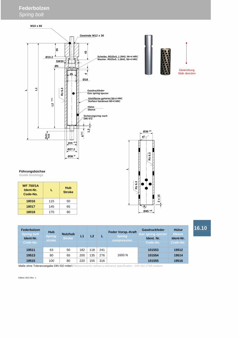
18016 115 50
18017 145 65
18018 170 80
19511 63 50 182 118 241 101553 1951219513 80 65 200 135 276 101554 1951419515 100 80 220 155 316 101555 19516
Maße ohne Toleranzangabe DIN ISO mittel / Measurements without a tolerance specification - DIN ISO 2768 medium
Edition 2012 Rev. 1
FederbolzenSpring bolt
16.10
1600 N
FederbolzenSpring bolt
Ident-Nr.Code-No.
HubSpringstroke
NutzhubStroke L1
Feder Vorsp.-KraftSpring
compression
GasdruckfederGas spring ejector
Ident. Nr.Code-No.
HülseSleeve
Ident-Nr.Code-No.
WF 750/1AIdent-Nr.Code-No.
L HubStroke
L2 L
FührungsbüchseGuide bushings
Ø26 +0.1
Ø27.2
Ø36 f7
L2+0
.1
L1L
35
43
Ø18
Ø10.2SW30
M10 x 60
Gewinde M12 x 30
GasdruckfederGas spring ejector
Gleitfläche gehärtet 58+4 HRCSurface hardened 58+4 HRC
HülseSleeve
Sicherungsring nachDIN 472
1.3
6-0.1
Nut
z-hu
b
Rz
6.3
4
Ø36 H7
Ø45 m6
Rz
6.3
Rz
6.3
L
2x
15
GleitrichtungSlide direction
Ø5
Scheibe, RD25x5, 1.2842, 56+4 HRCWasher. RD25x5. 1.2842, 56+4 HRC
25
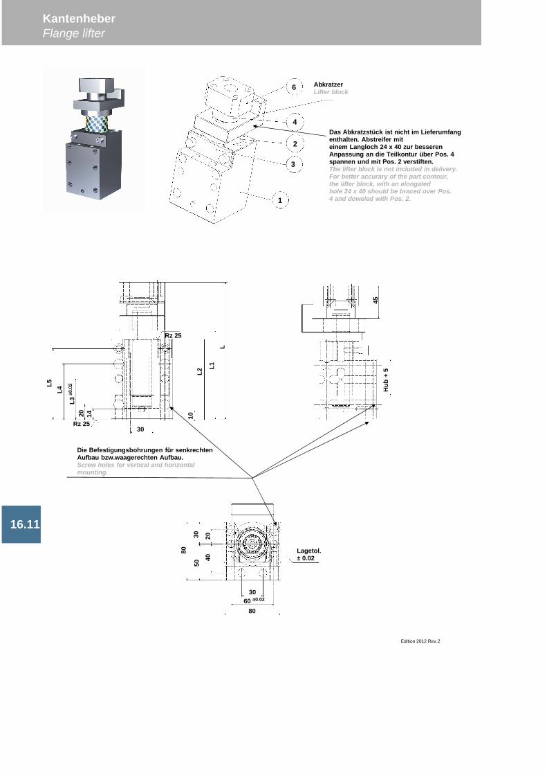
KantenheberFlange lifter
Edition 2012 Rev.2
16.11
6
4
2
3
1
30
1420L3
±0.0
2
L4L5
10L2
L1L
Rz 25
Rz 25
Hub
+5
45
30 2040
50
80
3060 ±0.02
80
Lagetol.± 0.02
AbkratzerLifter block
Das Abkratzstück ist nicht im Lieferumfangenthalten. Abstreifer miteinem Langloch 24 x 40 zur besserenAnpassung an die Teilkontur über Pos. 4spannen und mit Pos. 2 verstiften.The lifter block is not included in delivery.For better accurary of the part contour,the lifter block, with an elongatedhole 24 x 40 should be braced over Pos.4 and doweled with Pos. 2.
Die Befestigungsbohrungen für senkrechtenAufbau bzw.waagerechten Aufbau.Screw holes for vertical and horizontalmounting.
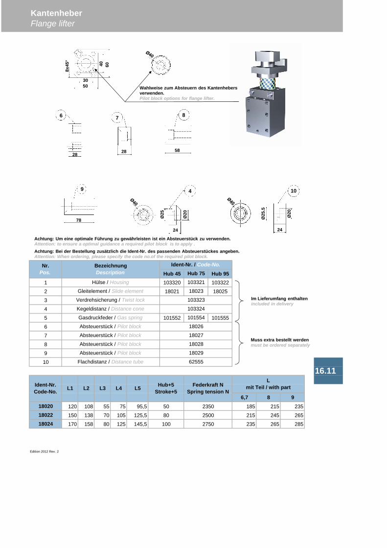
Hub 45 Hub 951 103320 103322
2 18021 18025
3
4
5 101552 101555
6
7
8
9
10
6,7 8 918020 120 108 55 75 95,5 185 215 23518022 150 138 70 105 125,5 215 245 26518024 170 158 80 125 145,5 235 265 285
Edition 2012 Rev. 2
16.11
KantenheberFlange lifter
L5 Hub+5Stroke+5
Ident-Nr.Code-No. L1 L2 L3 L4
Hub 75103321
50
80
100
Federkraft NSpring tension N
2350
2500
2750
18026
18027
18028
18029
103324
Flachdistanz / Distance tube 62555
Lmit Teil / with part
Absteuerstück / Pilot block
Nr.Pos.
BezeichnungDescription
Ident-Nr. / Code-No.
Absteuerstück / Pilot block
Absteuerstück / Pilot block
Absteuerstück / Pilot block
Hülse / Housing
Gleitelement / Slide element
Verdrehsicherung / Twist lock
Kegeldistanz / Distance cone
Gasdruckfeder / Gas spring
18023
103323
101554
3050
8x45
°
40 60
24
Ø20
Ø25
4
Ø20
Ø25
.5
24
10
28
6
28
7
58
8
78
9
Wahlweise zum Absteuern des Kantenhebersverwenden.Pilot block options for flange lifter.
Achtung: Bei der Bestellung zusätzlich die Ident-Nr. des passenden Absteuerstückes angeben.Attention: When ordering, please specify the code no.of the required pilot block.
Achtung: Um eine optimale Führung zu gewährleisten ist ein Absteuerstück zu verwenden.Attention: to ensure a optimal guidance a required pilot block is to apply .
Im Lieferumfang enthaltenincluded in delivery
Muss extra bestellt werdenmust be ordered separately
Führungssäule (f6) ohne Nut nach DIN 9833, Form D
Guide posts (f6) with groove for safety plate
Guide posts (f6) with groove for spring ring
Guide posts (f6) without groove with long heel
Guide posts (f6) with no hardened bottom
Guide posts (g6) without groove (expired)
Führungssäulen (g6) mit Nut für Sicherungsplatte (ausgelaufen)Guide posts (g6) with groove for safety plate (expired)
Guide posts (g6) with groove for spring ring (expired)
Säulen - TragzapfenGuide posts - Trunnions 17
17.1 Guide posts (f6) without groove acc. to DIN 9833, style D
17.1 Führungssäulen (f6) mit Nut für Sicherungsplatte
17.1 Führungssäulen (f6) mit Nut für Sprengring
17.1 Führungssäulen (f6) ohne Nut für schwimmende Lagerung
17.3
17.3 Führungssäulen (g6) mit Sprengringnut (ausgelaufen)
17.2 Führungssäulen (f6) mit ungehärtetem Fuß
17.3 Führungssäulen (g6) ohne Nut (ausgelaufen)
Führungssäulen (g6) ohne Nut fürschwimmende Lagerung (ausgelaufen)Guide posts (g6) without groove with long heel (expired)
Guide posts with clamp
Guide posts without clamp
Bolzen mit AchshalterBolts with axle support
Tragzapfen nach VDI 3366Trunnions acc. to VDI 3366
17Säulen - TragzapfenGuide posts - Trunnions
17.4
17.3
Tragbolzen mit Ringsicherung nach VDI 336617.12 Bolts with ring protection acc. to VDI 3366
17.7
Führungssäulen mit Klammer
Führungssäulen ohne Klammer
17.11
17.8
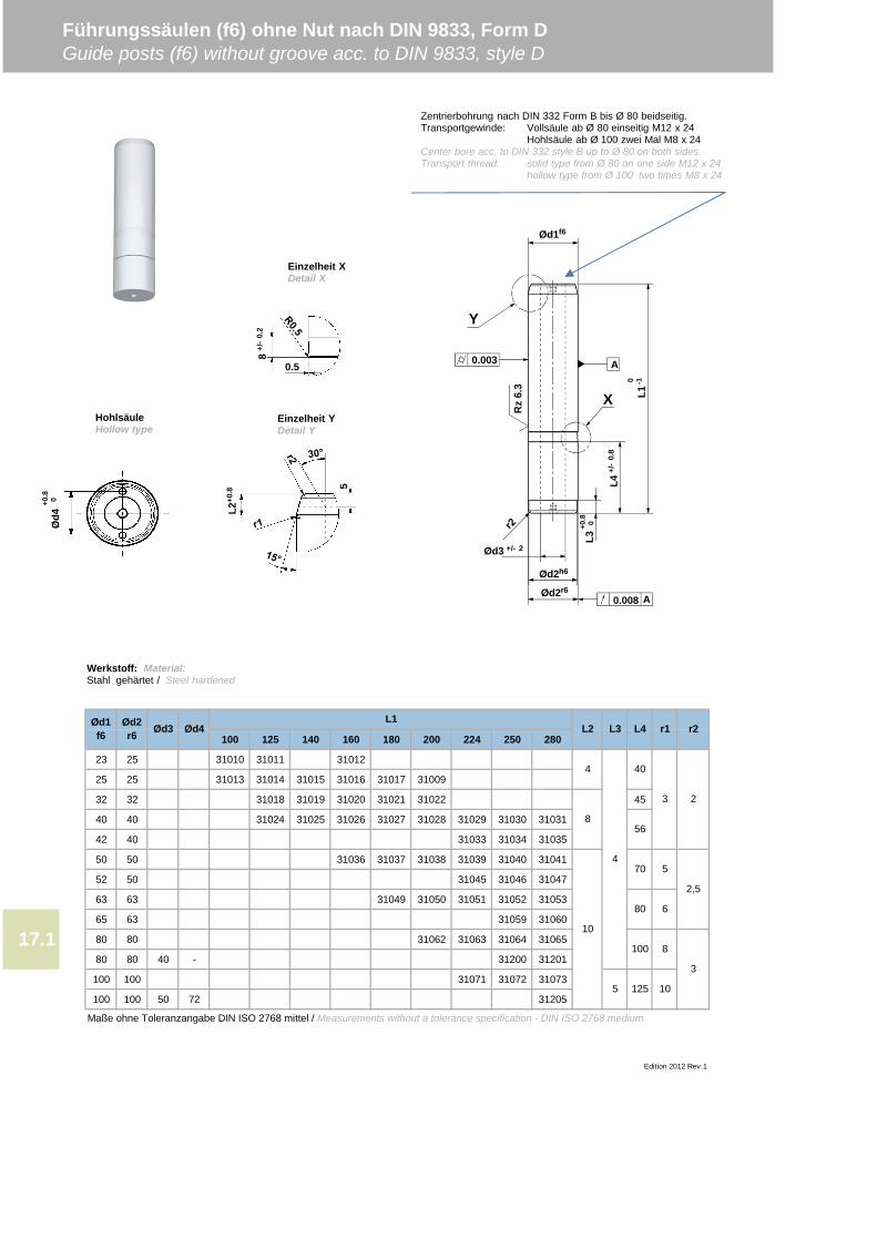
100 125 140 160 180 200 224 250 280
23 25 31010 31011 31012
25 25 31013 31014 31015 31016 31017 31009
32 32 31018 31019 31020 31021 31022 45
40 40 31024 31025 31026 31027 31028 31029 31030 31031
42 40 31033 31034 31035
50 50 31036 31037 31038 31039 31040 31041
52 50 31045 31046 31047
63 63 31049 31050 31051 31052 31053
65 63 31059 31060
80 80 31062 31063 31064 31065
80 80 40 - 31200 31201
100 100 31071 31072 31073
100 100 50 72 31205
Maße ohne Toleranzangabe DIN ISO 2768 mittel / Measurements without a tolerance specification - DIN ISO 2768 medium
Führungssäulen (f6) ohne Nut nach DIN 9833, Form DGuide posts (f6) without groove acc. to DIN 9833, style D
r1 r2
40
Edition 2012 Rev.1
10
80
100
6
8
10
2,5
3
17.1
3 2
570
56
L4L1
L3
125
4
8
4
5
Ød2r6
Ød1f6 Ød3 Ød4 L2
0.003
Ød2r6
Ød2h6
Ød3 +/- 2
0.008 A
A
Ød1f6
Rz
6.3
L4+/
-0.
8
0 -1L1
Y
+0.8 0
L3
X
Werkstoff: Material:Stahl gehärtet / Steel hardened
L2+0
.8 5
Einzelheit XDetail X
Einzelheit YDetail Y
0.5
8+/
-0.
2
Ød4
+0.8 0
Zentrierbohrung nach DIN 332 Form B bis Ø 80 beidseitig.Transportgewinde: Vollsäule ab Ø 80 einseitig M12 x 24
Hohlsäule ab Ø 100 zwei Mal M8 x 24Center bore acc. to DIN 332 style B up to Ø 80 on both sides.Transport thread: solid type from Ø 80 on one side M12 x 24
hollow type from Ø 100 two times M8 x 24
HohlsäuleHollow type
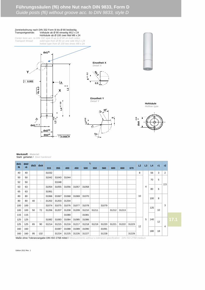
315 355 400 450 500 550 560 600 650 670
40 40 31032 8 56 3 2
50 50 31042 31043 31044
52 50 31048
63 63 31054 31055 31056 31057 31058
65 63 31061
80 80 31066 31067 31068 31069 31070
80 80 40 - 31202 31203 31204
100 100 31074 31075 31076 31077 31078 31079
100 100 50 72 31206 31207 31208 31209 31210 31211 31212 31213
115 115 31080 31081
125 125 31082 31083 31084 31085 31086
125 125 65 90 31214 31215 31216 31217 31218 31219 31220 31221 31222 31223
160 160 31087 31088 31089 31090 31091
160 160 95 132 31224 31225 31226 31227 31228 31229
Maße ohne Toleranzangabe DIN ISO 2768 mittel / Measurements without a tolerance specification - DIN ISO 2768 medium
Edition 2012 Rev. 1
Führungssäulen (f6) ohne Nut nach DIN 9833, Form DGuide posts (f6) without groove acc. to DIN 9833, style D
17.1
Ød1f6
Ød2r6 Ød3 Ød4 L4L3 r2
L
70
10
80
100
125
140
L2 r1
2,5
3
10
4
180
5
6
8
12
18
12
4
5
0.003
Ød2r6
Ød2h6
Ød3 +/- 2
0.008 A
A
Ød1f6
Rz
6.3
L4+/
-0.
8
0 -1L1X
Y
+0.8 0
L3
Werkstoff: Material:Stahl gehärtet / Steel hardened
Einzelheit XDetail X
Einzelheit YDetail Y
Zentrierbohrung nach DIN 332 Form B bis Ø 80 beidseitig.Transportgewinde: Vollsäule ab Ø 80 einseitig M12 x 24
Hohlsäule ab Ø 100 zwei Mal M8 x 24Center bore acc. to DIN 332 style B up to Ø 80 on both sides.Transport thread: solid type from Ø 80 on one side M12 x 24
hollow type from Ø 100 two times M8 x 24
0.5
8+/
-0.
2L2
+0.8 5
Ød4
+0.8 0
HohlsäuleHollow type
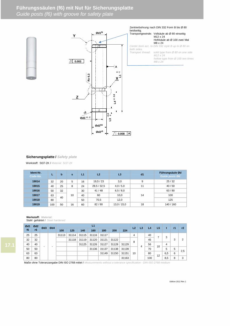
32 20 5 16
40 25 8 24
50 32 30
63 40
80 50
100 50 16 60
100 125 140 160 180 200 22425 25 31113 31114 31115 31116 31117 4 40
32 32 31118 31119 31120 31121 31122 45
40 40 31125 31126 31127 31128 31129 56 4
50 50 31136 31137 31138 31139 70 5 5
80 80 31163 100 8,5 8 3
Maße ohne Toleranzangabe DIN ISO 2768 mittel / Measurements without a tolerance specification - DIN ISO 2768 medium
Führungssäulen (f6) mit Nut für SicherungsplatteGuide posts (f6) with groove for safety plate
Edition 2012 Rev.1
Ød1f6
Ød2r6 Ød3 Ød4
L1L2 r1 r2L5 t
2
2,5
8
L4
- -
63 63 31149 31150
4
19015 28,5 / 32,5 4,0 / 5,0
6,5 / 8,0
L3
17.1
11
14
18
31151 80
L2 L3 Führungsäule ØdGuide posts Ødd1
25 / 32919014 19,5 / 23 3,0
Ident-Nr.Code-No. L b s L1
19019 82 / 90 13,0 / 15,0 140 / 160
40 / 50
126,5 6
100
3
10
7
10
3
19018 70,5 12,0 125
101901740
60 10,0
19016 41 / 48 63 / 80
0.003
Ød2h6
Ød3 +/- 2
A
Ød1f6
Rz
6.3
0 -1L1X
Y
Z
Ød2r60.008 A
+0.8 0
L3
L4+/
-0.
8
Werkstoff: Material:Stahl gehärtet / Steel hardened
Werkstoff: St37-2K / Material: St37-2K
Sicherungsplatte / Safety plate
Zentrierbohrung nach DIN 332 Form B bis Ø 80beidseitig.Transportgewinde: Vollsäule ab Ø 80 einseitig
M12 x 24Hohlsäule ab Ø 100 zwei MalM8 x 24
Center bore acc. to DIN 332 style B up to Ø 80 onboth sides.Transport thread: solid type from Ø 80 on one side
M12 x 24hollow type from Ø 100 two timesM8 x 24
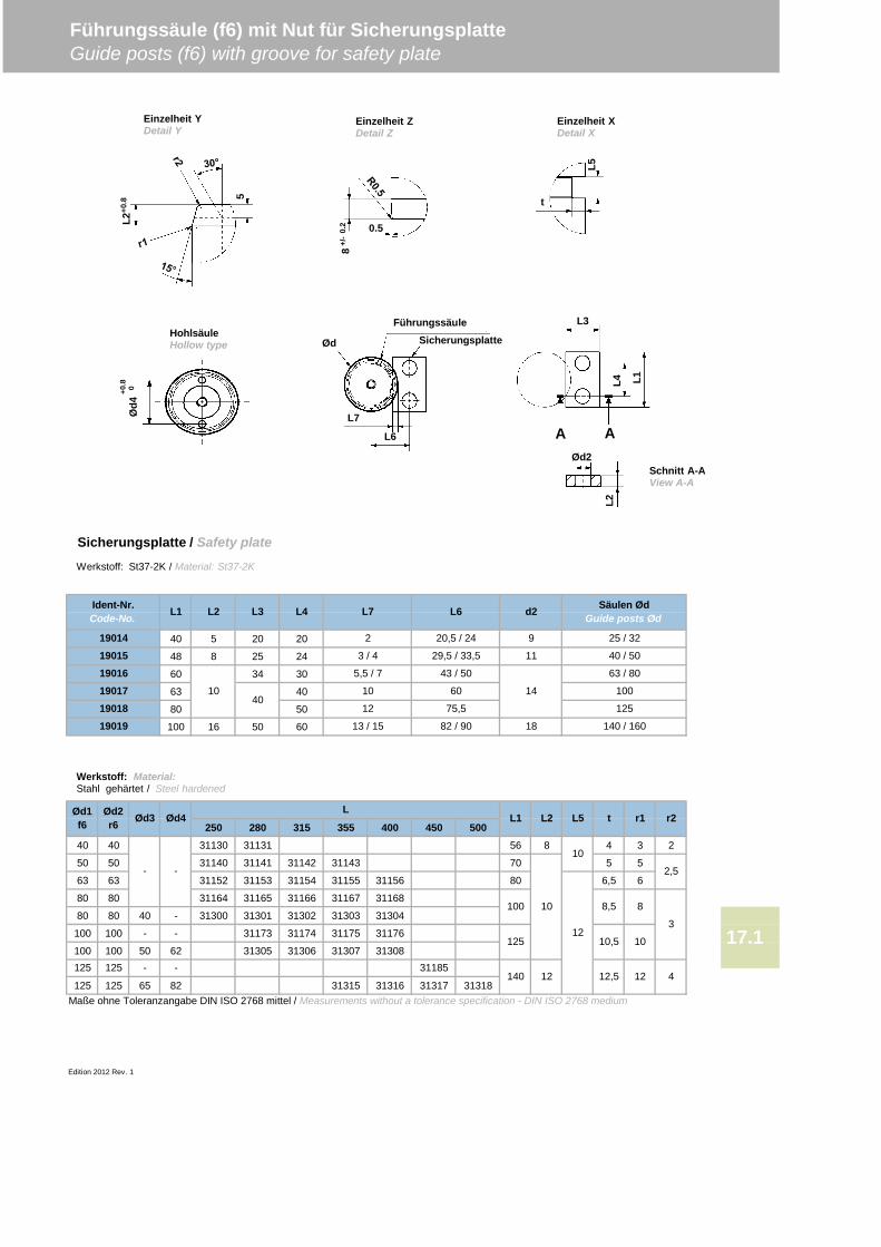
40 5 20 20
48 8 25 24
60 34 30
63 40
80 50
100 16 50 60
250 280 315 355 400 450 50040 40 31130 31131 56 8 4 3 2
50 50 31140 31141 31142 31143 70 5 5
63 63 31152 31153 31154 31155 31156 80 6,5 6
80 80 31164 31165 31166 31167 31168
80 80 40 - 31300 31301 31302 31303 31304
100 100 - - 31173 31174 31175 31176
100 100 50 62 31305 31306 31307 31308
125 125 65 82 31315 31316 31317 31318Maße ohne Toleranzangabe DIN ISO 2768 mittel / Measurements without a tolerance specification - DIN ISO 2768 medium
Edition 2012 Rev. 1
140 / 160
25 / 32
40 / 50
63 / 80
100
125
9
11
14
18
20,5 / 24
29,5 / 33,5
43 / 50
60
13 / 15
1901775,5
82 / 90
40
Führungssäule (f6) mit Nut für SicherungsplatteGuide posts (f6) with groove for safety plate
1901419015
L7 L6
2,5
Ød1f6
Ød2r6 Ød3 Ød4 t
LL1 L2 L5
- -
r1 r2
125
100
140
17.13
10
12
10
8,5
10,5
8
10
12 12,5 12 4
2
3 / 4
5,5 / 7
10
L4L3L2L1Ident-Nr.Code-No.
Säulen ØdGuide posts Ødd2
19016
125 125 31185- -
1901819019
10
12
Werkstoff: Material:Stahl gehärtet / Steel hardened
Werkstoff: St37-2K / Material: St37-2K
Sicherungsplatte / Safety plate
t
0.5
8+/
-0.
2
L5
L3
L1L4
A AØd2
L2
SicherungsplatteFührungssäule
L7
L6
Ød
Einzelheit YDetail Y
Einzelheit ZDetail Z
Einzelheit XDetail X
Schnitt A-AView A-A
L2+0
.8 5
Ød4
+0.8 0
HohlsäuleHollow type
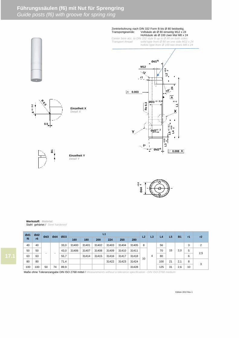
160 180 200 224 250 280
40 40 33,0 31400 31401 31402 31403 31404 31405 8 56 3 2
50 50 43,0 31406 31407 31408 31409 31410 31411 70 5
63 63 55,7 31414 31415 31416 31417 31418 80 6
80 80 71,4 31422 31423 31424 100 21 2,1 8
100 100 50 74 89,9 31428 125 31 2,6 10
Maße ohne Toleranzangabe DIN ISO 2768 mittel / Measurements without a tolerance specification - DIN ISO 2768 medium
2,5
3
L3Ød3 Ød4 r1 r2
Führungssäulen (f6) mit Nut für SprengringGuide posts (f6) with groove for spring ring
Ød1f6
Ød2r6
Edition 2012 Rev.1
ØD3 B1
10
2,0- -
17.1
L1L4L2 L5
4
15
Werkstoff: Material:Stahl gehärtet / Steel hardened
B1
8+/
-0.
2
0.5
Einzelheit XDetail X
Einzelheit YDetail Y
Ød4
+0.8 0
0.003
Ød2r6
Ød3+/- 2
Ød1f6
Rz
6.3
X
Y
M12
L5+/
-0.
124
ØD3 +/- 0.10A
L3+0
.8 0
0.008
0 -1L1
Zentrierbohrung nach DIN 332 Form B bis Ø 80 beidseitig.Transportgewinde: Vollsäule ab Ø 80 einseitig M12 x 24
Hohlsäule ab Ø 100 zwei Mal M8 x 24Center bore acc. to DIN 332 style B up to Ø 80 on both sides.Transport thread: solid type from Ø 80 on one side M12 x 24
hollow type from Ø 100 two times M8 x 24
L4+0
.8 0
L2+0
.8 0
A
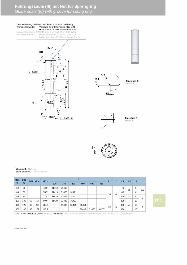
315 355 400 450 500 560
50 50 43,0 31412 31413 70 5
63 63 55,7 31419 31420 31421 80 6
80 80 71,4 31425 31426 31427 100 21 8
100 100 50 72 89,9 31429 31430 31431 125 10
125 125 65 90 114,9 31432 31433 31434 140 12
160 160 95 132 148,9 31435 31436 31437 180 18
Edition 2012 Rev. 1
Führungssäule (f6) mit Nut für SprengringGuide posts (f6) with groove for spring ring
Ød1f6
Ød2r6 Ød3 Ød4 L2 L3 L4 L5ØD3
L1r1 r2
2,5
4
Maße ohne Toleranzangabe DIN ISO 2768 mittel / Measurements without a tolerance specification - DIN ISO 2768 medium
17.13
- -10 4
512
15
31
A
Werkstoff: Material:Stahl gehärtet / Steel hardened
B1
8+/
-0.
20.5
Einzelheit XDetail X
Einzelheit YDetail Y
Ød4
+0.8 0
0.003
Ød2r6
Ød3+/- 2
Ød1f6
Rz
6.3
X
Y
M12
L5+/
-0.
1
24
ØD3 +/- 0.10A
L3+0
.8 0
0.008
0 -1L1
Zentrierbohrung nach DIN 332 Form B bis Ø 80 beidseitig.Transportgewinde: Vollsäule ab Ø 80 einseitig M12 x 24
Hohlsäule ab Ø 100 zwei Mal M8 x 24Center bore acc. to DIN 332 style B up to Ø 80 on both sides.Transport thread: solid type from Ø 80 on one side M12 x 24
hollow type from Ø 100 two times M8 x 24
L4+0
.8 0
L2+0
.8 0
A
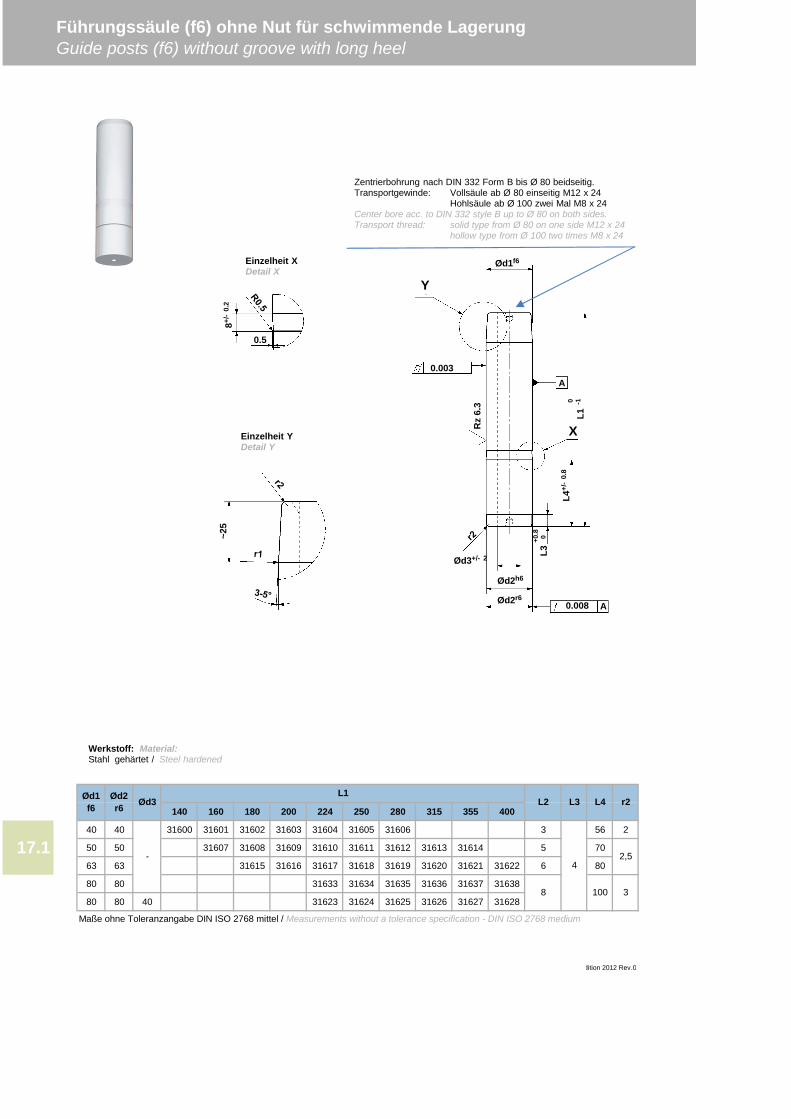
140 160 180 200 224 250 280 315 355 400
40 40 31600 31601 31602 31603 31604 31605 31606 3 56 2
50 50 31607 31608 31609 31610 31611 31612 31613 31614 5 70
63 63 31615 31616 31617 31618 31619 31620 31621 31622 6 80
80 80 31633 31634 31635 31636 31637 31638
80 80 40 31623 31624 31625 31626 31627 31628
Maße ohne Toleranzangabe DIN ISO 2768 mittel / Measurements without a tolerance specification - DIN ISO 2768 medium
Führungssäule (f6) ohne Nut für schwimmende LagerungGuide posts (f6) without groove with long heel
Edition 2012 Rev.0
38 100
42,5-17.1
L4L2 r2L1Ød1
f6Ød2r6 Ød3 L3
0.003
Ød2r6
Ød2h6
Ød3+/- 2
0.008 A
A
Ød1f6
Rz
6.3
L4+/
-0.
80 -1
L1
X
Y
+0.8 0
L3
Werkstoff: Material:Stahl gehärtet / Steel hardened
~25
0.5
8+/-
0.2
Einzelheit XDetail X
Einzelheit YDetail Y
Zentrierbohrung nach DIN 332 Form B bis Ø 80 beidseitig.Transportgewinde: Vollsäule ab Ø 80 einseitig M12 x 24
Hohlsäule ab Ø 100 zwei Mal M8 x 24Center bore acc. to DIN 332 style B up to Ø 80 on both sides.Transport thread: solid type from Ø 80 on one side M12 x 24
hollow type from Ø 100 two times M8 x 24
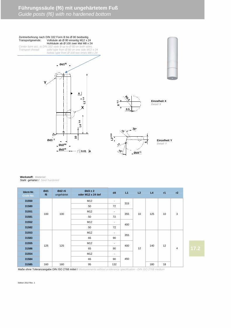
31550 M12 -
31580 50 72
31551 M12 -
31581 50 72
31552 M12 -
31582 50 72
31553 M12 -
31583 65 90
31555 M12 -
31586 65 90
31554 M12 -
31584 65 90
31585 160 160 95 132 180 18
Maße ohne Toleranzangabe DIN ISO 2768 mittel / Measurements without a tolerance specification - DIN ISO 2768 medium
Edition 2012 Rev. 1
Führungssäule (f6) mit ungehärtetem FußGuide posts (f6) with no hardened bottom
17.2
Ident-Nr.Code-No.
d4 L1 L4 r1 r2
315
355 10100 100 3
125 125
L2Ød1f6
Ød2 r6ungehärtet
Ød3 ± 2oder M12 x 24 tief
4
400
355
400
450
12
125
140
10
12
Werkstoff: Material:Stahl gehärtet / Steel hardened
Ød2r6
Ød2h6
Ød3 2
0.01 A
A
Ød1f6
10L4
0.8
0 -1.6
L1
X
Y
0.5
80.
2
L2+0
.8
5
Ød4+1
Einzelheit XDetail X
Einzelheit YDetail Y
Zentrierbohrung nach DIN 332 Form B bis Ø 80 beidseitig.Transportgewinde: Vollsäule ab Ø 80 einseitig M12 x 24
Hohlsäule ab Ø 100 zwei Mal M8 x 24Center bore acc. to DIN 332 style B up to Ø 80 on both sides.Transport thread: solid type from Ø 80 on one side M12 x 24
hollow type from Ø 100 two times M8 x 24
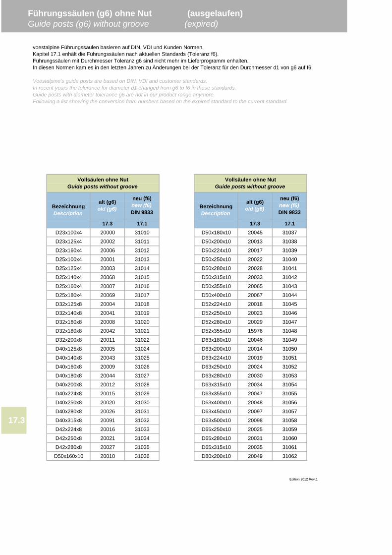
17.3 17.1 17.3 17.1D23x100x4 20000 31010 D50x180x10 20045 31037
D23x125x4 20002 31011 D50x200x10 20013 31038
D23x160x4 20006 31012 D50x224x10 20017 31039
D25x100x4 20001 31013 D50x250x10 20022 31040
D25x125x4 20003 31014 D50x280x10 20028 31041
D25x140x4 20068 31015 D50x315x10 20033 31042
D25x160x4 20007 31016 D50x355x10 20065 31043
D25x180x4 20069 31017 D50x400x10 20067 31044
D32x125x8 20004 31018 D52x224x10 20018 31045
D32x140x8 20041 31019 D52x250x10 20023 31046
D32x160x8 20008 31020 D52x280x10 20029 31047
D32x180x8 20042 31021 D52x355x10 15976 31048
D32x200x8 20011 31022 D63x180x10 20046 31049
D40x125x8 20005 31024 D63x200x10 20014 31050
D40x140x8 20043 31025 D63x224x10 20019 31051
D40x160x8 20009 31026 D63x250x10 20024 31052
D40x180x8 20044 31027 D63x280x10 20030 31053
D40x200x8 20012 31028 D63x315x10 20034 31054
D40x224x8 20015 31029 D63x355x10 20047 31055
D40x250x8 20020 31030 D63x400x10 20048 31056
D40x280x8 20026 31031 D63x450x10 20097 31057
D40x315x8 20091 31032 D63x500x10 20098 31058
D42x224x8 20016 31033 D65x250x10 20025 31059
D42x250x8 20021 31034 D65x280x10 20031 31060
D42x280x8 20027 31035 D65x315x10 20035 31061
D50x160x10 20010 31036 D80x200x10 20049 31062
neu (f6)new (f6)DIN 9833
Vollsäulen ohne NutGuide posts without groove
Vollsäulen ohne NutGuide posts without groove
Edition 2012 Rev.1
17.3
Führungssäulen (g6) ohne Nut (ausgelaufen)Guide posts (g6) without groove (expired)
voestalpine Führungssäulen basieren auf DIN, VDI und Kunden Normen.Kapitel 17.1 enhält die Führungssäulen nach aktuellen Standards (Toleranz f6).Führungssäulen mit Durchmesser Toleranz g6 sind nicht mehr im Lieferprogramm enhalten.In diesen Normen kam es in den letzten Jahren zu Änderungen bei der Toleranz für den Durchmesser d1 von g6 auf f6.
Voestalpine's guide posts are based on DIN, VDI and customer standards.In recent years the tolerance for diameter d1 changed from g6 to f6 in these standards.Guide posts with diameter tolerance g6 are not in our product range anymore.Following a list showing the conversion from numbers based on the expired standard to the current standard.
neu (f6)new (f6)DIN 9833
alt (g6)old (g6)Bezeichnung
DescriptionBezeichnungDescription
alt (g6)old (g6)
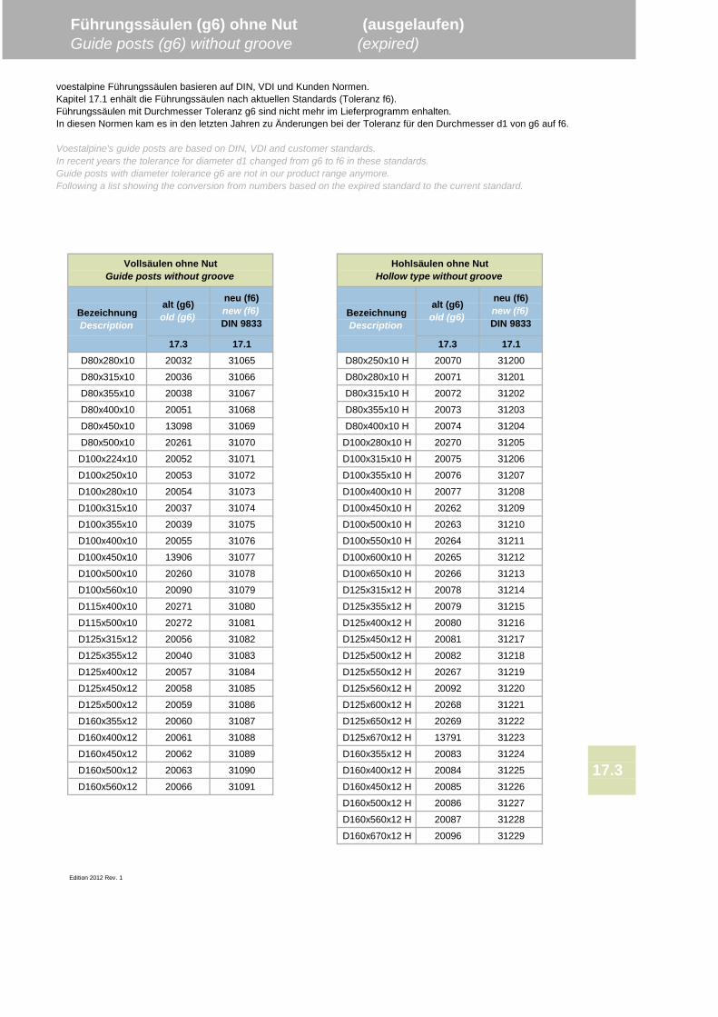
17.3 17.1 17.3 17.1D80x280x10 20032 31065 D80x250x10 H 20070 31200
D80x315x10 20036 31066 D80x280x10 H 20071 31201
D80x355x10 20038 31067 D80x315x10 H 20072 31202
D80x400x10 20051 31068 D80x355x10 H 20073 31203
D80x450x10 13098 31069 D80x400x10 H 20074 31204
D80x500x10 20261 31070 D100x280x10 H 20270 31205
D100x224x10 20052 31071 D100x315x10 H 20075 31206
D100x250x10 20053 31072 D100x355x10 H 20076 31207
D100x280x10 20054 31073 D100x400x10 H 20077 31208
D100x315x10 20037 31074 D100x450x10 H 20262 31209
D100x355x10 20039 31075 D100x500x10 H 20263 31210
D100x400x10 20055 31076 D100x550x10 H 20264 31211
D100x450x10 13906 31077 D100x600x10 H 20265 31212
D100x500x10 20260 31078 D100x650x10 H 20266 31213
D100x560x10 20090 31079 D125x315x12 H 20078 31214
D115x400x10 20271 31080 D125x355x12 H 20079 31215
D115x500x10 20272 31081 D125x400x12 H 20080 31216
D125x315x12 20056 31082 D125x450x12 H 20081 31217
D125x355x12 20040 31083 D125x500x12 H 20082 31218
D125x400x12 20057 31084 D125x550x12 H 20267 31219
D125x450x12 20058 31085 D125x560x12 H 20092 31220
D125x500x12 20059 31086 D125x600x12 H 20268 31221
D160x355x12 20060 31087 D125x650x12 H 20269 31222
D160x400x12 20061 31088 D125x670x12 H 13791 31223
D160x450x12 20062 31089 D160x355x12 H 20083 31224
D160x500x12 20063 31090 D160x400x12 H 20084 31225
D160x560x12 20066 31091 D160x450x12 H 20085 31226
D160x500x12 H 20086 31227
D160x560x12 H 20087 31228
D160x670x12 H 20096 31229
Edition 2012 Rev. 1
17.3
Führungssäulen (g6) ohne Nut (ausgelaufen)Guide posts (g6) without groove (expired)
voestalpine Führungssäulen basieren auf DIN, VDI und Kunden Normen.Kapitel 17.1 enhält die Führungssäulen nach aktuellen Standards (Toleranz f6).Führungssäulen mit Durchmesser Toleranz g6 sind nicht mehr im Lieferprogramm enhalten.In diesen Normen kam es in den letzten Jahren zu Änderungen bei der Toleranz für den Durchmesser d1 von g6 auf f6.
Voestalpine's guide posts are based on DIN, VDI and customer standards.In recent years the tolerance for diameter d1 changed from g6 to f6 in these standards.Guide posts with diameter tolerance g6 are not in our product range anymore.Following a list showing the conversion from numbers based on the expired standard to the current standard.
neu (f6)new (f6)DIN 9833
Vollsäulen ohne NutGuide posts without groove
Hohlsäulen ohne NutHollow type without groove
BezeichnungDescription
alt (g6)old (g6)
neu (f6)new (f6)DIN 9833
BezeichnungDescription
alt (g6)old (g6)
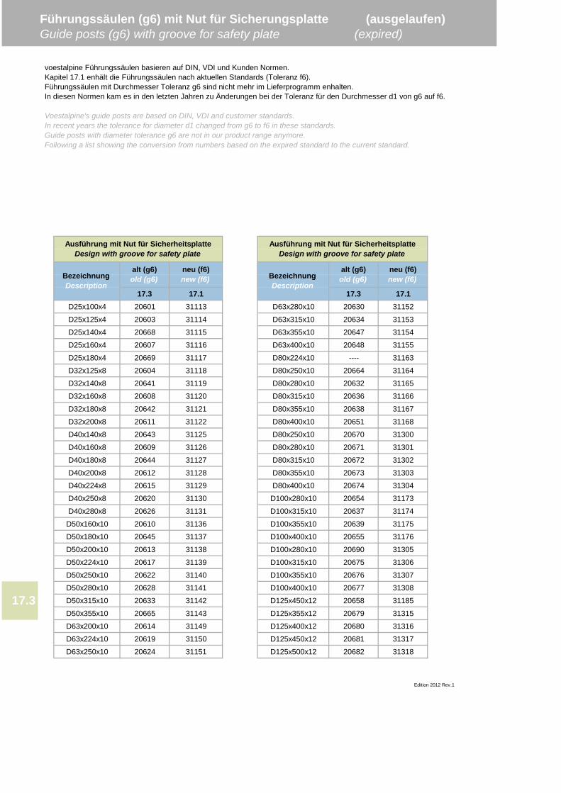
17.3 17.1 17.3 17.1D25x100x4 20601 31113 D63x280x10 20630 31152
D25x125x4 20603 31114 D63x315x10 20634 31153
D25x140x4 20668 31115 D63x355x10 20647 31154
D25x160x4 20607 31116 D63x400x10 20648 31155
D25x180x4 20669 31117 D80x224x10 ---- 31163
D32x125x8 20604 31118 D80x250x10 20664 31164
D32x140x8 20641 31119 D80x280x10 20632 31165
D32x160x8 20608 31120 D80x315x10 20636 31166
D32x180x8 20642 31121 D80x355x10 20638 31167
D32x200x8 20611 31122 D80x400x10 20651 31168
D40x140x8 20643 31125 D80x250x10 20670 31300
D40x160x8 20609 31126 D80x280x10 20671 31301
D40x180x8 20644 31127 D80x315x10 20672 31302
D40x200x8 20612 31128 D80x355x10 20673 31303
D40x224x8 20615 31129 D80x400x10 20674 31304
D40x250x8 20620 31130 D100x280x10 20654 31173
D40x280x8 20626 31131 D100x315x10 20637 31174
D50x160x10 20610 31136 D100x355x10 20639 31175
D50x180x10 20645 31137 D100x400x10 20655 31176
D50x200x10 20613 31138 D100x280x10 20690 31305
D50x224x10 20617 31139 D100x315x10 20675 31306
D50x250x10 20622 31140 D100x355x10 20676 31307
D50x280x10 20628 31141 D100x400x10 20677 31308
D50x315x10 20633 31142 D125x450x12 20658 31185
D50x355x10 20665 31143 D125x355x12 20679 31315
D63x200x10 20614 31149 D125x400x12 20680 31316
D63x224x10 20619 31150 D125x450x12 20681 31317
D63x250x10 20624 31151 D125x500x12 20682 31318
Edition 2012 Rev.1
BezeichnungDescription
alt (g6)old (g6)
neu (f6)new (f6) Bezeichnung
Description
alt (g6)old (g6)
neu (f6)new (f6)
17.3
Führungssäulen (g6) mit Nut für Sicherungsplatte (ausgelaufen)Guide posts (g6) with groove for safety plate (expired)
voestalpine Führungssäulen basieren auf DIN, VDI und Kunden Normen.Kapitel 17.1 enhält die Führungssäulen nach aktuellen Standards (Toleranz f6).Führungssäulen mit Durchmesser Toleranz g6 sind nicht mehr im Lieferprogramm enhalten.In diesen Normen kam es in den letzten Jahren zu Änderungen bei der Toleranz für den Durchmesser d1 von g6 auf f6.
Voestalpine's guide posts are based on DIN, VDI and customer standards.In recent years the tolerance for diameter d1 changed from g6 to f6 in these standards.Guide posts with diameter tolerance g6 are not in our product range anymore.Following a list showing the conversion from numbers based on the expired standard to the current standard.
Ausführung mit Nut für SicherheitsplatteDesign with groove for safety plate
Ausführung mit Nut für SicherheitsplatteDesign with groove for safety plate
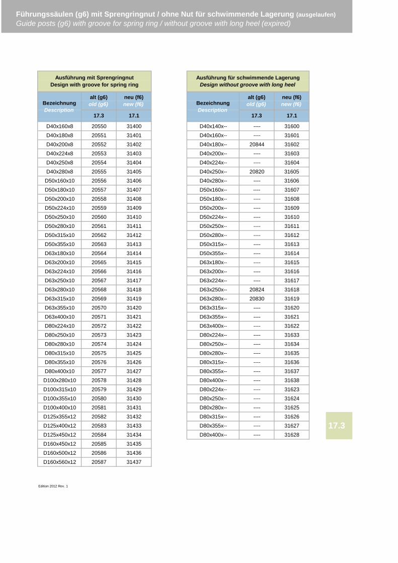
D40x160x8 20550 31400 D40x140x-- ---- 31600
D40x180x8 20551 31401 D40x160x-- ---- 31601
D40x200x8 20552 31402 D40x180x-- 20844 31602
D40x224x8 20553 31403 D40x200x-- ---- 31603
D40x250x8 20554 31404 D40x224x-- ---- 31604
D40x280x8 20555 31405 D40x250x-- 20820 31605
D50x160x10 20556 31406 D40x280x-- ---- 31606
D50x180x10 20557 31407 D50x160x-- ---- 31607
D50x200x10 20558 31408 D50x180x-- ---- 31608
D50x224x10 20559 31409 D50x200x-- ---- 31609
D50x250x10 20560 31410 D50x224x-- ---- 31610
D50x280x10 20561 31411 D50x250x-- ---- 31611
D50x315x10 20562 31412 D50x280x-- ---- 31612
D50x355x10 20563 31413 D50x315x-- ---- 31613
D63x180x10 20564 31414 D50x355x-- ---- 31614
D63x200x10 20565 31415 D63x180x-- ---- 31615
D63x224x10 20566 31416 D63x200x-- ---- 31616
D63x250x10 20567 31417 D63x224x-- ---- 31617
D63x280x10 20568 31418 D63x250x-- 20824 31618
D63x315x10 20569 31419 D63x280x-- 20830 31619
D63x355x10 20570 31420 D63x315x-- ---- 31620
D63x400x10 20571 31421 D63x355x-- ---- 31621
D80x224x10 20572 31422 D63x400x-- ---- 31622
D80x250x10 20573 31423 D80x224x-- ---- 31633
D80x280x10 20574 31424 D80x250x-- ---- 31634
D80x315x10 20575 31425 D80x280x-- ---- 31635
D80x355x10 20576 31426 D80x315x-- ---- 31636
D80x400x10 20577 31427 D80x355x-- ---- 31637
D100x280x10 20578 31428 D80x400x-- ---- 31638
D100x315x10 20579 31429 D80x224x-- ---- 31623
D100x355x10 20580 31430 D80x250x-- ---- 31624
D100x400x10 20581 31431 D80x280x-- ---- 31625
D125x355x12 20582 31432 D80x315x-- ---- 31626
D125x400x12 20583 31433 D80x355x-- ---- 31627
D125x450x12 20584 31434 D80x400x-- ---- 31628
D160x450x12 20585 31435
D160x500x12 20586 31436
D160x560x12 20587 31437
Edition 2012 Rev. 1
17.3
alt (g6)old (g6)
neu (f6)new (f6)
17.3
alt (g6)old (g6)
neu (f6)new (f6)
17.3 17.1
Ausführung mit SprengringnutDesign with groove for spring ring
Ausführung für schwimmende LagerungDesign without groove with long heel
Führungssäulen (g6) mit Sprengringnut / ohne Nut für schwimmende Lagerung (ausgelaufen)Guide posts (g6) with groove for spring ring / without groove with long heel (expired)
17.1
BezeichnungDescription
BezeichnungDescription
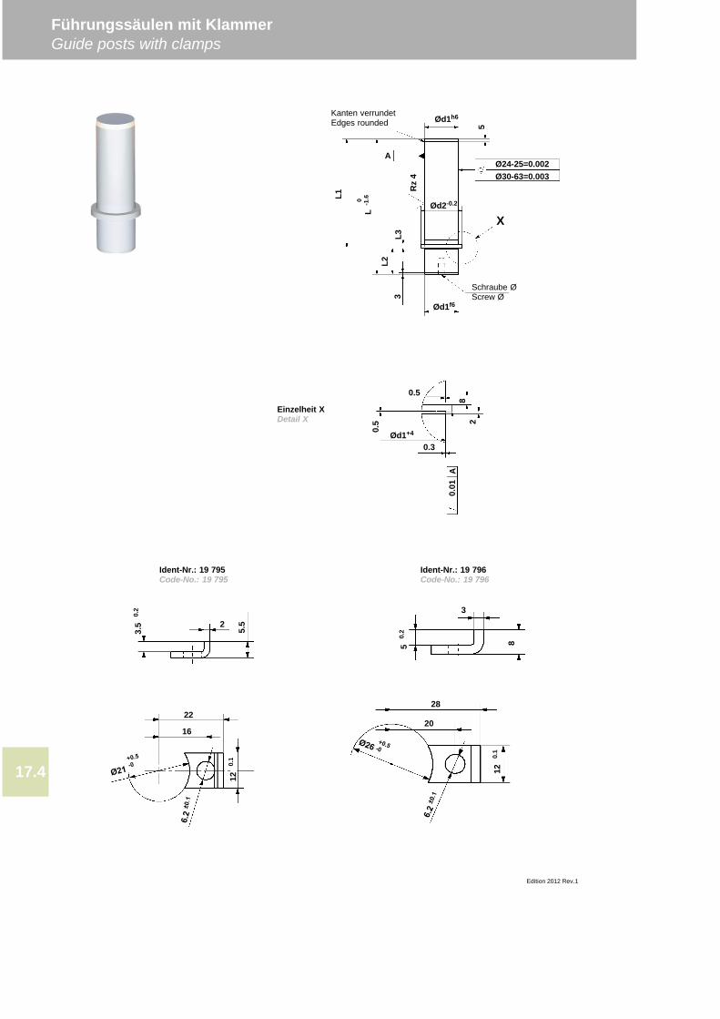
Führungssäulen mit KlammerGuide posts with clamps
Edition 2012 Rev.1
17.4
Rz
4
A
L3
Ød1f6
Ød1h6
Ød2-0.2
3L2
0 -1.6
L
Ø24-25=0.002Ø30-63=0.003
X
Kanten verrundetEdges rounded
Schraube ØScrew Ø
5
0.5
Ød1+4
0.3
0.5
82
A0.
01
2
3.5
0.2
5.5
22
16
120.
1
3
850.
2
28
20
120.
1
Ident-Nr.: 19 795Code-No.: 19 795
Einzelheit XDetail X
Ident-Nr.: 19 796Code-No.: 19 796
L1
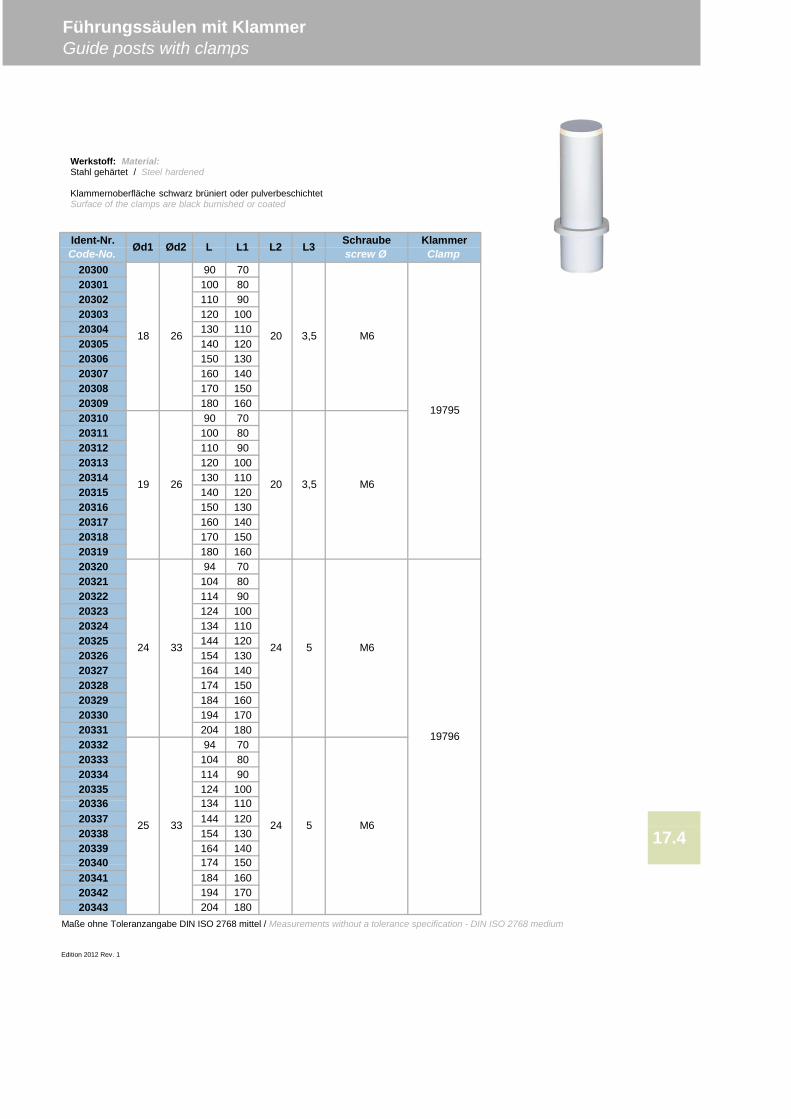
20300 90 7020301 100 8020302 110 9020303 120 10020304 130 11020305 140 12020306 150 13020307 160 14020308 170 15020309 180 16020310 90 7020311 100 8020312 110 9020313 120 10020314 130 11020315 140 12020316 150 13020317 160 14020318 170 15020319 180 16020320 94 7020321 104 8020322 114 9020323 124 10020324 134 11020325 144 12020326 154 13020327 164 14020328 174 15020329 184 16020330 194 17020331 204 18020332 94 7020333 104 8020334 114 9020335 124 100
20337 144 12020338 154 13020339 164 140
20341 184 16020342 194 17020343 204 180
Maße ohne Toleranzangabe DIN ISO 2768 mittel / Measurements without a tolerance specification - DIN ISO 2768 medium
Edition 2012 Rev. 1
Führungssäulen mit KlammerGuide posts with clamps
18 26
19 26
20336
20340
17.4
24
5 M6
33
25 33
174
134
150
110
20 3,5 M6
20 M6
KlammerClamp
19795
19796
Ident-Nr.Code-No. Ød1 Ød2 L L1 L2 L3 Schraube
screw Ø
3,5
24 5 M6
24
Werkstoff: Material:Stahl gehärtet / Steel hardened
Klammernoberfläche schwarz brüniert oder pulverbeschichtetSurface of the clamps are black burnished or coated
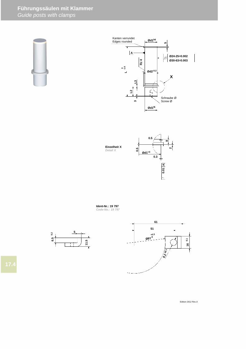
Führungssäulen mit KlammerGuide posts with clamps
Edition 2012 Rev.0
17.4
Rz
4
A
L3
Ød1f6
Ød1h6
Ød2-0.2
3L2
0 -1.6
L
Ø24-25=0.002Ø30-63=0.003
X
Kanten verrundetEdges rounded
Schraube ØScrew Ø
5
0.5
Ød1+4
0.3
0.5
82
A0.
01
5
11.56.
50.
2
61
51
160.
1
Ident-Nr.: 19 797Code-No.: 19 797
Einzelheit XDetail X
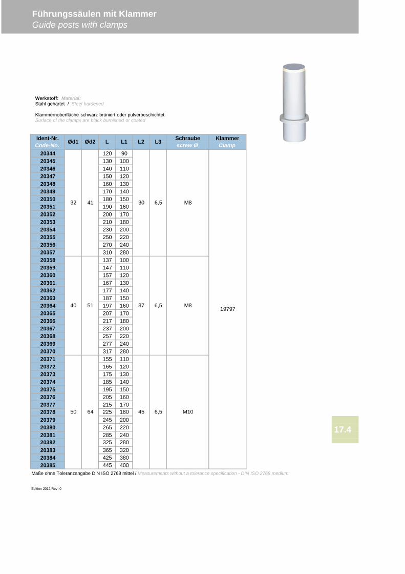
20344 120 9020345 130 10020346 140 11020347 150 12020348 160 13020349 170 14020350 180 15020351 190 16020352 200 17020353 210 18020354 230 20020355 250 22020356 270 24020357 310 28020358 137 10020359 147 11020360 157 12020361 167 13020362 177 14020363 187 15020364 197 16020365 207 17020366 217 18020367 237 20020368 257 22020369 277 24020370 317 28020371 155 11020372 165 12020373 175 13020374 185 14020375 195 15020376 205 16020377 215 170
20379 245 20020380 265 22020381 285 240
20383 365 32020384 425 38020385 445 400
Maße ohne Toleranzangabe DIN ISO 2768 mittel / Measurements without a tolerance specification - DIN ISO 2768 medium
Edition 2012 Rev. 0
Ident-Nr.Code-No. Ød1 Ød2 L L1 L2 L3 Schraube
screw ØKlammerClamp
Führungssäulen mit KlammerGuide posts with clamps
32 41 30 M8
37 6,5 M8
6,5
17.420382 325 280
45 6,5 M1020378 50 64
19797
225 180
40 51
Werkstoff: Material:Stahl gehärtet / Steel hardened
Klammernoberfläche schwarz brüniert oder pulverbeschichtetSurface of the clamps are black burnished or coated

Führungssäulen mit KlammerGuide posts with clamps
Edition 2012 Rev.0
17.4
Rz
4
A
L3
Ød1f6
Ød1h6
Ød2-0.2
3L2
0 -1.6
L
Ø24-25=0.002Ø30-63=0.003
X
Kanten verrundetEdges rounded
Schraube ØScrew Ø
5
0.5
Ød1+4
0.3
0.5
82
A0.
01
5
11.56.
50.
2
61
51
160.
1
Ident-Nr.: 19 797Code-No.: 19 797
Einzelheit XDetail X
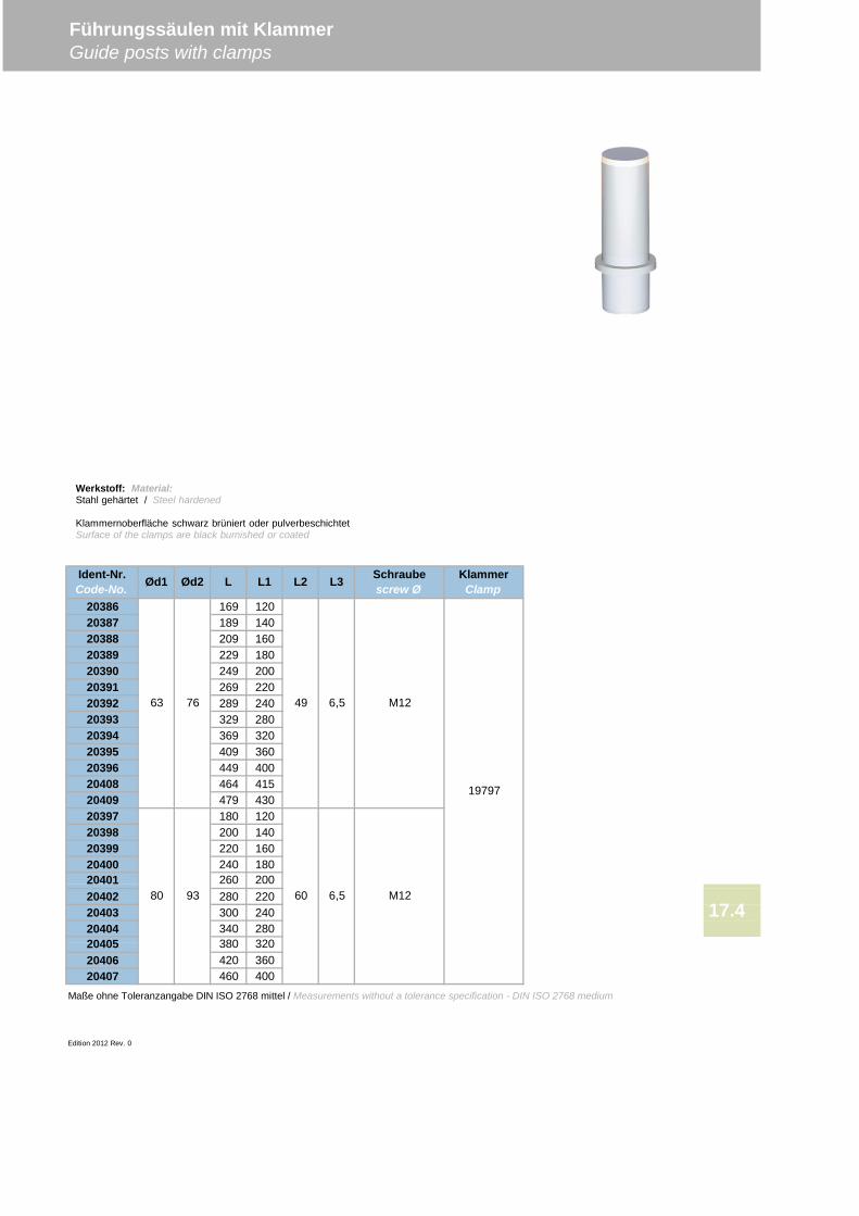
20386 169 12020387 189 14020388 209 16020389 229 18020390 249 20020391 269 22020392 289 24020393 329 28020394 369 32020395 409 36020396 449 40020408 464 41520409 479 43020397 180 12020398 200 14020399 220 16020400 240 180
20402 280 22020403 300 24020404 340 280
20406 420 36020407 460 400
Maße ohne Toleranzangabe DIN ISO 2768 mittel / Measurements without a tolerance specification - DIN ISO 2768 medium
Edition 2012 Rev. 0
M12
Führungssäulen mit KlammerGuide posts with clamps
Ident-Nr.Code-No. Ød1 Ød2 L L1 L2 L3 Schraube
screw ØKlammerClamp
20401 260
20405 380 320
20080 93
63 76 49
6017.4
19797
M126,5
6,5
Werkstoff: Material:Stahl gehärtet / Steel hardened
Klammernoberfläche schwarz brüniert oder pulverbeschichtetSurface of the clamps are black burnished or coated
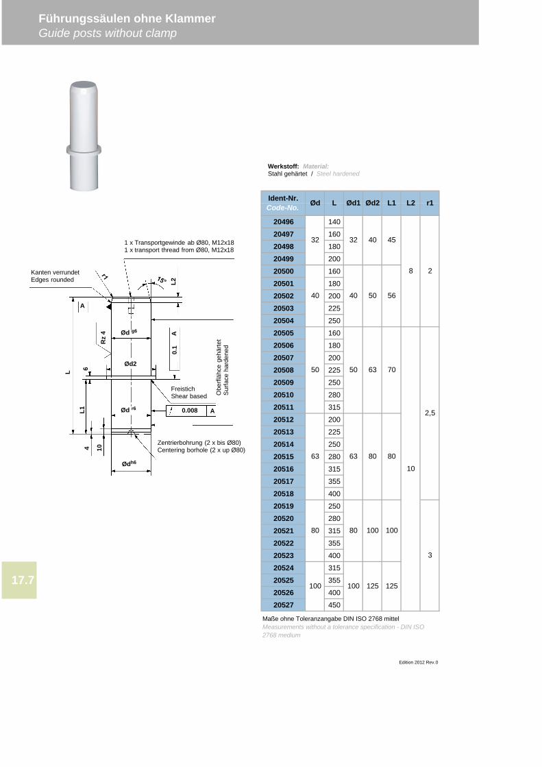
20496 140
20497 160
20498 180
20499 200
20500 160
20501 180
20502 200
20503 225
20504 250
20505 160
20506 180
20507 200
20508 225
20509 250
20510 280
20511 315
20512 200
20513 225
20514 250
20515 280
20516 315
20517 355
20518 400
20519 250
20520 280
20521 315
20522 355
20523 400
20524 315
20525 355
20526 400
20527 450
Führungssäulen ohne KlammerGuide posts without clamp
L2 r1
32 32 40 45
8
Ident-Nr.Code-No. Ød L
Edition 2012 Rev.0
80 80 100
Ød2 L1Ød1
10
50 63 70
63 80
Maße ohne Toleranzangabe DIN ISO 2768 mittelMeasurements without a tolerance specification - DIN ISO2768 medium
17.7
2
80
40 40 50 56
2,5
3
100
100 100 125 125
63
50
Werkstoff: Material:Stahl gehärtet / Steel hardened
Rz
4
A
Ødh6
L1
Kanten verrundetEdges rounded
1 x Transportgewinde ab Ø80, M12x181 x transport thread from Ø80, M12x18
Obe
rfläh
cege
härte
tS
urfa
ceha
rden
ed
FreistichShear based
Zentrierbohrung (2 x bis Ø80)Centering borhole (2 x up Ø80)
Ød r6
Ød2
Ød g6
L
4 10
A
A0.008
0.1
L2
6
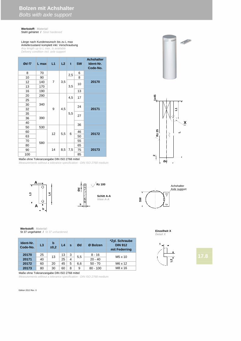
8 70 610 90 812 14013 17016 190 1320 29025303235364050 53060 4663 5070 5580 6590 75100 85
20170 25 13 3 8 - 1620171 40 25 4 20 - 40
20173 80 30 60 8 9 80 - 100
Edition 2012 Rev. 0
Bolzen mit AchshalterBolts with axle support
20170
AchshalterIdent-Nr.Code-No.
Ød f7 L max
17.8
L1 L2 t SW
20172
Ident-Nr.Code-No. L3 b
±0,2 L4
7 3,5
2,5
3,510
60 20
13
9
Maße ohne Toleranzangabe DIN ISO 2768 mittelMeasurements without a tolerance specification - DIN ISO 2768 medium
*Zyl. SchraubeDIN 912
mit Federring
50 - 70
Ød Ø Bolzens
M6 x 12
20171
20172
20173
4,5
Maße ohne Toleranzangabe DIN ISO 2768 mittelMeasurements without a tolerance specification - DIN ISO 2768 medium
17
24
27
36
5,5
5,5
6
340
390
580
14
12
45 5 6,6M8 x 16
M5 x 105,5
4,5
8,5 7,5
Werkstoff: Material:Stahl gehärtet / Steel hardened
Länge nach Kundenwunsch bis zu L maxAnlieferzustand komplett inkl. VerschraubungAny length up to L max. is availableDelivery condition incl. axle support
Werkstoff: Material:St 37 ungehärtet / St 37 unhardened
ØdR
z25 L
L1
21x
45
X
AchshalterAxle support
SW
t
L2
Rz 100
s
Ød
b
L3 L4
A
A
Einzelheit XDetail X
Schitt A-AView A-A
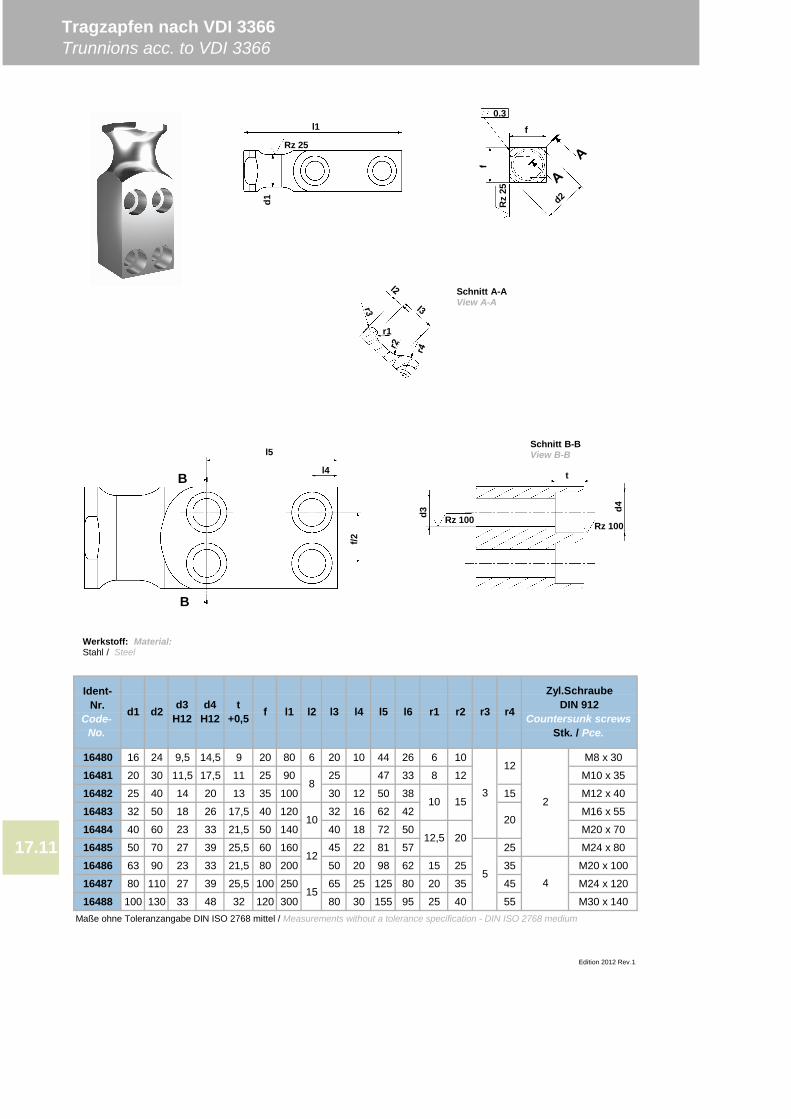
16480 16 24 9,5 14,5 9 20 80 6 20 10 44 26 6 10 M8 x 30
16481 20 30 11,5 17,5 11 25 90 25 47 33 8 12 M10 x 35
16482 25 40 14 20 13 35 100 30 12 50 38 15 M12 x 40
16483 32 50 18 26 17,5 40 120 32 16 62 42 M16 x 55
16484 40 60 23 33 21,5 50 140 40 18 72 50 M20 x 70
16485 50 70 27 39 25,5 60 160 45 22 81 57 25 M24 x 80
16486 63 90 23 33 21,5 80 200 50 20 98 62 15 25 35 M20 x 100
16487 80 110 27 39 25,5 100 250 65 25 125 80 20 35 45 M24 x 120
16488 100 130 33 48 32 120 300 80 30 155 95 25 40 55 M30 x 140Maße ohne Toleranzangabe DIN ISO 2768 mittel / Measurements without a tolerance specification - DIN ISO 2768 medium
Tragzapfen nach VDI 3366Trunnions acc. to VDI 3366
Ident-Nr.
Code-No.
d1 d2 d3H12
Edition 2012 Rev.1
l1 l2 l3 l4 r4
Zyl.SchraubeDIN 912
Countersunk screwsStk. / Pce.
r1 r2 r3
32
12
20
54
17.11
d4H12
t+0,5 f l5 l6
15
12,5 20
10 15
8
10
12
Werkstoff: Material:Stahl / Steel
t
Rz 100Rz 100d3 d4
f/2
l4
l5
B
BR
z25
0.3
f
f
r1
Rz 25
l1
d1
Schnitt A-AView A-A
Schnitt B-BView B-B
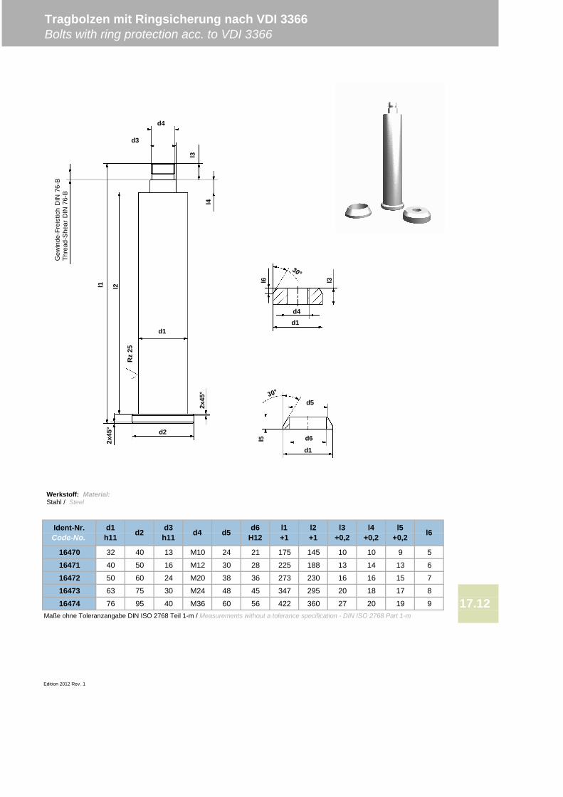
16470 32 40 13 M10 24 21 175 145 10 10 9 5
16471 40 50 16 M12 30 28 225 188 13 14 13 6
16472 50 60 24 M20 38 36 273 230 16 16 15 7
16473 63 75 30 M24 48 45 347 295 20 18 17 8
16474 76 95 40 M36 60 56 422 360 27 20 19 9Maße ohne Toleranzangabe DIN ISO 2768 Teil 1-m / Measurements without a tolerance specification - DIN ISO 2768 Part 1-m
Edition 2012 Rev. 1
Tragbolzen mit Ringsicherung nach VDI 3366Bolts with ring protection acc. to VDI 3366
d5
17.12
l6d6H12
l1+1
l2+1
l3+0,2
l4+0,2
l5+0,2
Ident-Nr.Code-No.
d1h11 d2 d3
h11 d4
Werkstoff: Material:Stahl / Steel
l6
d4d1
l3
l5 d6
d1
d5
d4
d3
l3
l4
l1 l2
d2
Rz
25
d1
Gew
inde
-Fre
istic
hD
IN76
-BTh
read
-She
arD
IN76
-B
2x45
°
2x45
°

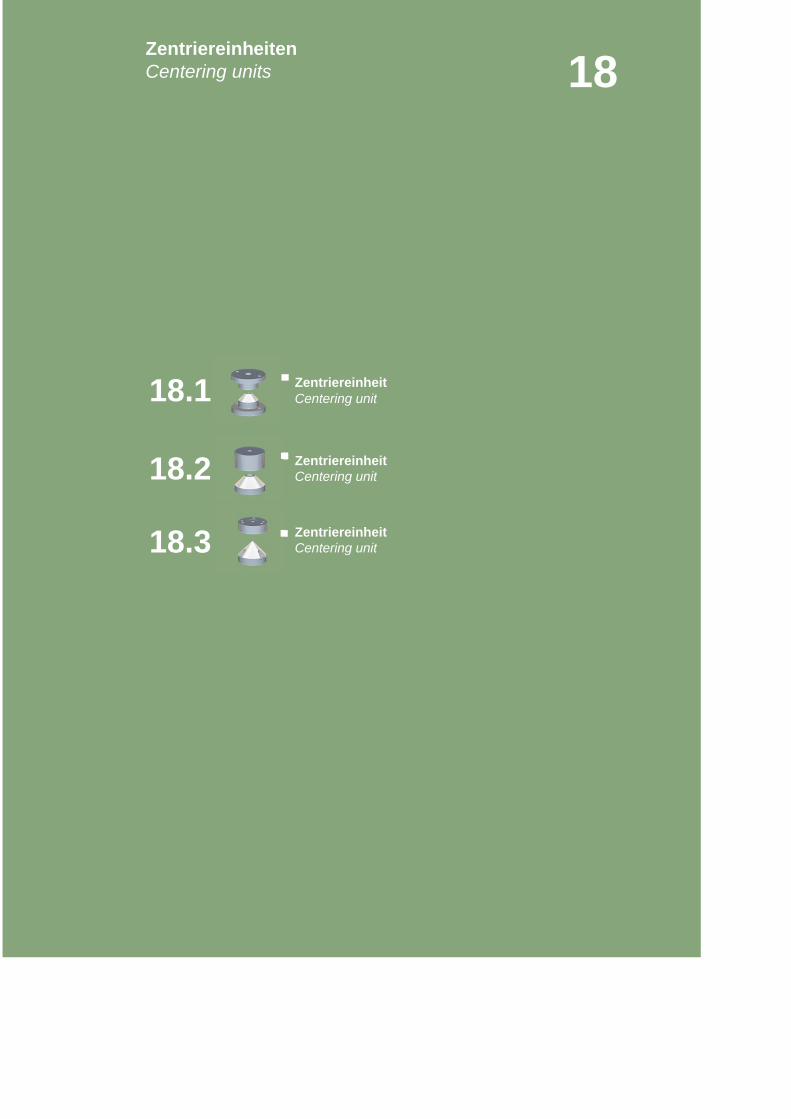
Centering unit
Centering unit
Centering unit
18
Zentriereinheit
Zentriereinheit
Zentriereinheit18.3
ZentriereinheitenCentering units
18.1
18.2
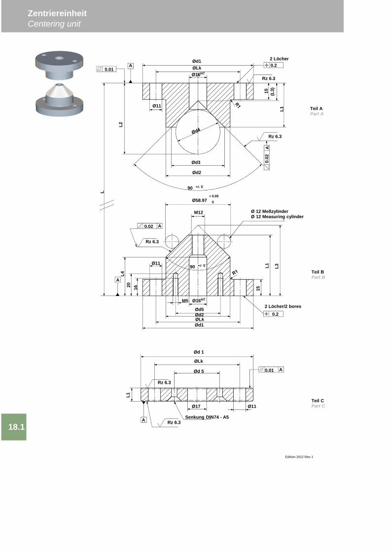
ZentriereinheitCentering unit
Edition 2012 Rev.1
18.1
0.2Ød1ØLkØ16H7
Ø11
Ød3
Ød2
15 (L3)
L1
0.02
0.01A
Rz 6.3
Rz 6.3
Ød1ØLkØd2
Ø16H7
Ø58.97+ 0.05
0
M12
0.02
A
A
Rz 6.3
Ø11
L4
15
L1 L3
0.2
Ø 12 MeßzylinderØ 12 Measuring cylinder
2 Löcher/2 bores
2 Löcher
LTeil APart A
Teil BPart B
L2
90 +/- 5`
90 +/- 5`A
Ød5
M5
20 16
Teil CPart C
ØLk
Ød 1
Ød 5
Rz 6.3
0.01 A
A Rz 6.3
Ø17 Ø11
Senkung DIN74 - A5
L1
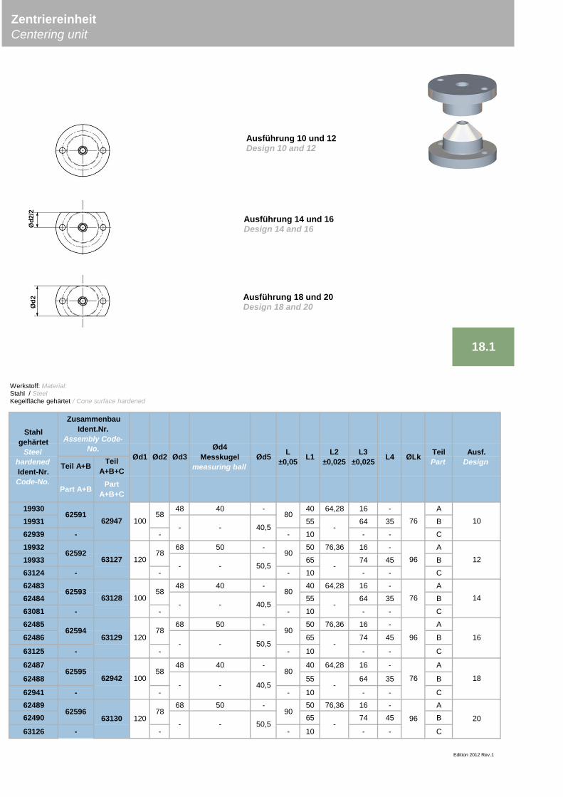
Teil A+B TeilA+B+C
Part A+B PartA+B+C
19930 48 40 - 40 64,28 16 - A
19931 55 64 35 B
62939 - - - 10 - - C
19932 68 50 - 50 76,36 16 - A
19933 65 74 45 B
63124 - - - 10 - - C
62483 48 40 - 40 64,28 16 - A
62484 55 64 35 B
63081 - - - 10 - - C
62485 68 50 - 50 76,36 16 - A
62486 65 74 45 B
63125 - - - 10 - - C
62487 48 40 - 40 64,28 16 - A
62488 55 64 35 B
62941 - - - 10 - - C62489 68 50 - 50 76,36 16 - A62490 65 74 45 B
63126 - - - 10 - - C
Edition 2012 Rev.1
Ausf.Design
Stahlgehärtet
SteelhardenedIdent-Nr.Code-No.
L±0,05 L1 L2
±0,025L3
±0,025Ød5Ød2Ød1
18.1
ZentriereinheitCentering unit
6259663130
6259562942
62593
ZusammenbauIdent.Nr.
Assembly Code-No.
6259162947
62592
62594
63128
63129
63127
120
58
78
58
78
58
78120
100
100
120
100
-
-
-
-
-
-
-
-
40,5
50,5
40,5
50,5
50,5
40,5
-
-
-
-
TeilPartØLkL4
Ød4Messkugel
measuring ballØd3
20
10
12
14
16
18
96
-
-
-
-
-
-
96
76
76
96
7680
90
90
90
80
80
Ausführung 10 und 12Design 10 and 12
Ausführung 14 und 16Design 14 and 16
Ausführung 18 und 20Design 18 and 20
Werkstoff: Material:Stahl / SteelKegelfläche gehärtet / Cone surface hardened
Ød2
/2Ø
d2
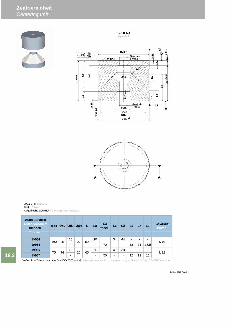
19934 88 10 - 54 44 - - -
19935 - - 70 - - 53 21 18,5
19936 62 9 - 40 30 - - -
19937 - - 56 - - 42 19 13Maße ohne Toleranzangabe DIN ISO 2768 mittel / Measurements without a tolerance specification - DIN ISO 2768 medium
L Lo Lutheor.
18.2
L5
ZentriereinheitCentering unit
Stahl gehärtetSteel hardened
Ident-Nr.Code-No.
Ød1 Ød2 Ød3 Ød4 Gewindethread
Edition 2012 Rev.0
100 98
75 74
26 80
20 65
M16
M12
L1 L2 L3 L4
2x45
A A
Schitt A-AView A-A
Rz
6.3 Ød4
0.05 A B0.05 C D
A
Ød3
Ød1 h7
GewindeThread1x
45
L5L1 L2
Ød1 h7
GewindeThreadRz 12.5
B
DC
L416
L3
1416
1x45
Lu+/
-0.0
1Lo
+/-0
.01
Ød4L
+/-0
.02
Ød2
Werkstoff: Material:Stahl / SteelKegelfläche gehärtet / Cone surface hardened
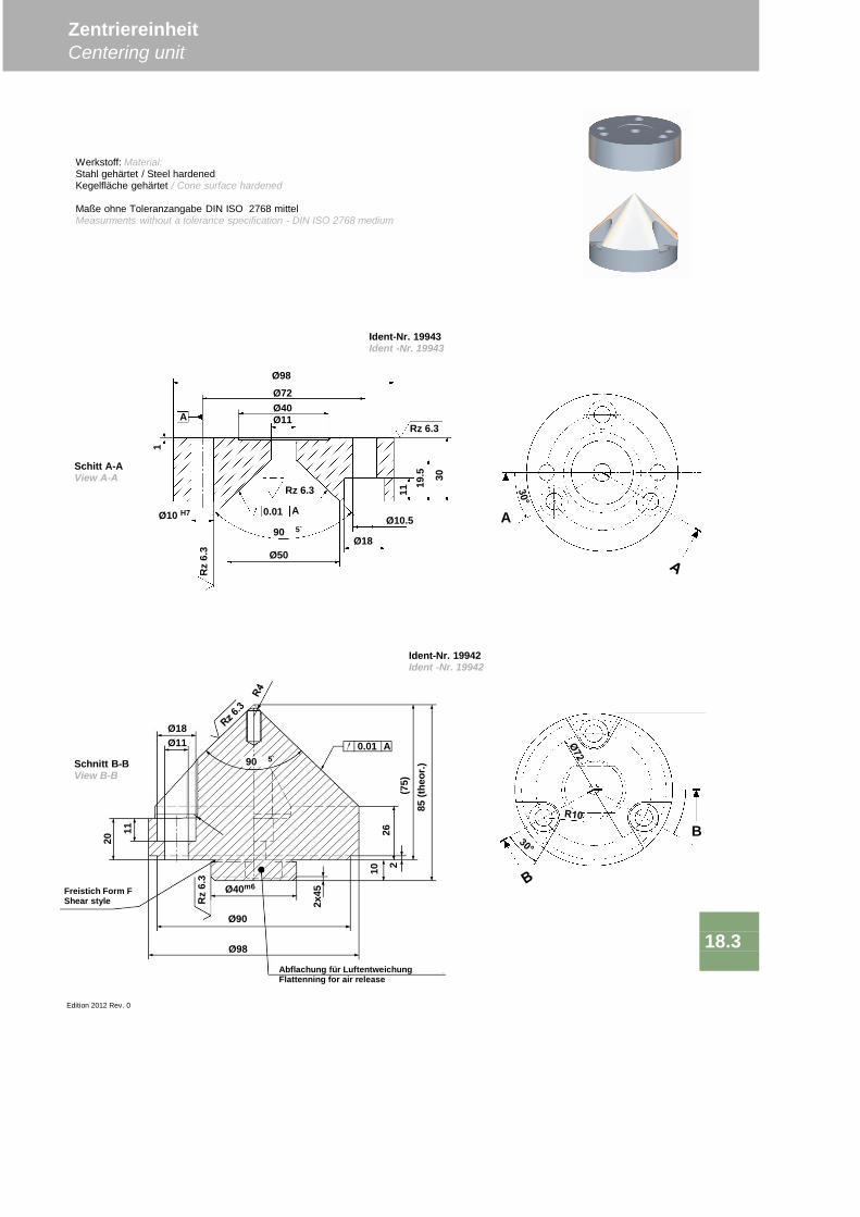
Edition 2012 Rev. 0
ZentriereinheitCentering unit
18.3
0.01 A
Ø18Ø11
11
20
Ø90
21026
(75)
85(th
eor.)
Rz
6.3
Ø40m6
2x45Freistich Form F
Shear style
Abflachung für LuftentweichungFlattenning for air release
90 5`
Ø98
Rz 6.3
A
0.01Ø10 H7
Ø98
11
1
Ø18
Ø72Ø40Ø11
A
Ø50
Ø10.5
19.5 30
Rz 6.3
Rz
6.3
Ident-Nr. 19943Ident -Nr. 19943
Ident-Nr. 19942Ident -Nr. 19942
Schnitt B-BView B-B
Schitt A-AView A-A
Werkstoff: Material:Stahl gehärtet / Steel hardenedKegelfläche gehärtet / Cone surface hardened
Maße ohne Toleranzangabe DIN ISO 2768 mittelMeasurments without a tolerance specification - DIN ISO 2768 medium
90 5`
B
A

Bolt guides
19
Bolzenfürhungen19.1
BolzenführungenBolt guides

Edition 2012 Rev. 0
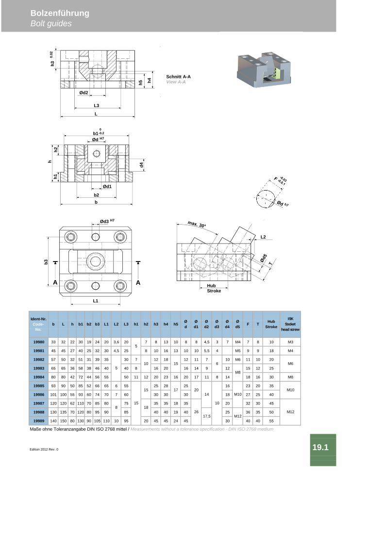
19980 33 32 22 30 19 24 20 3,6 20 7 8 13 10 8 8 4,5 3 7 M4 7 8 10 M3
19981 45 45 27 40 25 32 30 4,5 25 8 10 16 13 10 10 5,5 4 M5 9 9 18 M4
19982 57 50 32 51 31 39 35 30 7 12 18 12 11 7 10 M6 11 10 20
19983 65 65 36 58 38 46 40 40 8 16 20 16 14 9 12 15 12 25
19984 80 80 42 72 44 56 55 50 11 12 20 23 16 20 17 11 8 14 18 16 30 M8
19985 93 90 50 85 52 66 65 6 55 25 28 25 16 23 20 35
19986 101 100 55 93 60 74 70 7 60 30 30 30 18 27 25 40
19987 120 120 62 110 70 85 80 75 35 35 18 35 20 32 30 45
19988 130 135 70 120 80 95 90 85 40 40 19 40 25 36 35 50
19989 140 150 80 130 90 105 110 10 95 20 45 45 24 45 30 40 40 55
Maße ohne Toleranzangabe DIN ISO 2768 mittel / Measurements without a tolerance specification - DIN ISO 2768 medium
Edition 2012 Rev. 0
BolzenführungBolt guides
19.1
Ident-Nr.Code-
No.
ISKSocket
head screw
HubStroke
Ød
Ød1
Ød2
Ød3
Ød4
Ød5 F Tb L h b1 b2 b3 L1 L2 L3 h5
8
5
5
10
15
18
15
17
h1 h2 h3 h4
15
20
26
14
17,5
6
10
M10
M8
M12
M6
M10
M12
HubStroke
L2
AA
b3
Ød3 H7
L1
hh1
Ød1
Ød H7
b2
b10
-0.2
h2
d4
b
Ød2
L
h30.
02
h5
L3
h4
Schnitt A-AView A-A
DEUTSCHLAND / GERMANY ITALIEN / ITALY SÜDAMERIKA / USAvoestalpine Deutschland GmbH Maric S.A.S. di Rossato & C. SOUTH AMERICA / USAWilhelm-Wagenfeld-Straße 26 Via Milano 7 OCEANTEC LTDA.D-80807 München IT-23878 Verderio Superiore-LC Rua Gertrudes de Lima,53,Sala 12-1° andarT. +49/89/57835-238 T. +39/039/9281262 BR-09020-000 Santo André, Sao PauloF. +49/89/57835-277 F. +39/039/9517175 T. +55/11/[email protected] [email protected] [email protected]@voestalpine.com
ITALIEN / ITALY USA / USAHOLLAND / BELGIEN voestalpine Italia S.r.l. Bohler-Uddeholm Corp.NETHERLANDS / BELGIUM Via F. Turati, 29 2505 Millennium DriveTechnisches Büro Bäcker B.V. I- 20121 Milano USA-60124 Elgin, ILPieter Lieftinckweg 20 T. +39/02/29081-232 T. +1/630/883-3000NL-1505 HX Zaandam F. +39/02/29081-219 F. +1 630/883/3128T. +31/75/6818000 [email protected] [email protected]. +31/75/[email protected] SPANIEN / SPAIN CHINA / CHINA
Auxiliar de Troqueleria, S.A. voestalpine Eurostahl GmbHFRANKREICH / RUMÄNIEN / Pol, Ind. El Campillo, Pab. A-9 Representative Office of BeijingPORTUGAL/SPANIEN E-48509 Abanto - Zierbena Rm 1313, Lizhou Building,FRANCE / ROMANIA T. +34/94/6363-612 383 Huan Cheng Dong Lu,PORTUGAL/SPAIN F. +34/94/6363-658 Nan Qiao, Feng Xian, Shanghai 201400Carrasco SA [email protected] T. +86/21/6089-0708Carretera de l'Hospitalet 342 F. +86/21/6089-0709ES-08740 Cornellà de Llobregat, TSCHECHIEN / [email protected] THE CZECH REPUBLICT. +34/93/4746240 voestalpine R, s.r.o. TÜRKEI / TURKEYF. +34/93/4740058 Karlovo nám stí 31 GSB O LLESS MALAT SAN.VE PAZ.LTD. [email protected] CZ-120 00 Praha 2 Girne Mahallesi Çiçek Sokak No:5 Giri Kat 1/2
T. +420/224/9081-09 TR-81552 Maltepe, stanbulSLOWENIEN / SLOVENIJA F. +420/224/9081-04 T. +90/216/44210-89KERN [email protected] F. +90/216/44228-32Orodjarske Technology d.o.o. [email protected] - Hrpelje 41 TSCHECHIEN /SLO-6240 Kozina THE CZECH REPUBLICT. +386/5/616/5000 EICHLER COMPANY s.r.o.F. +386/5/616/5015 Na Prutech .p. 1063/[email protected] CZ-591 01 Ž ár nad Sázavou
T. +420/566/629357SÜDAFRIKA / SOUTH AFRICA F. +420/566/624323Tecno design C.C [email protected]. Box 11021ZA-0161 Maroelana POLEN / POLANDT. +27/12/347-3612 RAF Sp.j. Rafal & Janusz SliwarskiF. +27/12/347-2188 ul. Barska [email protected] PL-43-300 Bielsko-Biala
T. +48/33/82 71-600SCHWEDEN / NORWEGEN F. +48/33/81 62-392FINNLAND / DÄNEMARK [email protected] / NORWAYFINLAND / DENMARK POLEN / POLANDLagermetall AB LASKA Technika Przemyslowa SP.Z O.OBoskärsgatan 23 ul. Towarowa 35S-702 25 Örebro PL-43-100 TychyT. +46/19/104525 T. +48/32/32624-50F. +46/19/123855 F. +48/32/[email protected] [email protected]
voestalpine Giesserei Linz GmbHvoestalpine-Straße 3, 4020 Linz, AustriaTel. +43/50304/15-0, Fax +43/50304/55-8069E-Mail: [email protected]/giesserei
AUSLANDSVERTRETUNGEN / FOREIGN REPRENSENTATIVES
Kontaktdaten der voestalpine Eurostahl Vertriebsgesellschaft unter:http://www.voestalpine.com/eurostahl/Internationaler-Vertrieb