Embed Size (px)
Citation preview
Date: 21.04.2015
E Schaudt GmbH, Elektrotechnik und Apparatebau, Planckstraße 8, 88677 Markdorf, Germany, Tel. +49 7544 9577-0, Fax +49 7544 9577-29, www.schaudt--gmbh.de
822.213 BA / EN
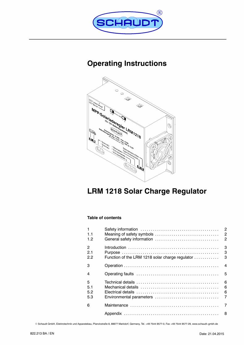
Operating Instructions
LRM 1218 Solar Charge Regulator
Table of contents
1 Safety information 2. . . . . . . . . . . . . . . . . . . . . . . . . . . . . . . . . . . . . .1.1 Meaning of safety symbols 2. . . . . . . . . . . . . . . . . . . . . . . . . . . . . . .1.2 General safety information 2. . . . . . . . . . . . . . . . . . . . . . . . . . . . . . .
2 Introduction 3. . . . . . . . . . . . . . . . . . . . . . . . . . . . . . . . . . . . . . . . . . . .2.1 Purpose 3. . . . . . . . . . . . . . . . . . . . . . . . . . . . . . . . . . . . . . . . . . . . . . .2.2 Function of the LRM 1218 solar charge regulator 3. . . . . . . . . . . .
3 Operation 4. . . . . . . . . . . . . . . . . . . . . . . . . . . . . . . . . . . . . . . . . . . . . .
4 Operating faults 5. . . . . . . . . . . . . . . . . . . . . . . . . . . . . . . . . . . . . . . .
5 Technical details 6. . . . . . . . . . . . . . . . . . . . . . . . . . . . . . . . . . . . . . . .5.1 Mechanical details 6. . . . . . . . . . . . . . . . . . . . . . . . . . . . . . . . . . . . . .5.2 Electrical details 6. . . . . . . . . . . . . . . . . . . . . . . . . . . . . . . . . . . . . . . .5.3 Environmental parameters 7. . . . . . . . . . . . . . . . . . . . . . . . . . . . . . .
6 Maintenance 7. . . . . . . . . . . . . . . . . . . . . . . . . . . . . . . . . . . . . . . . . . .
Appendix 8. . . . . . . . . . . . . . . . . . . . . . . . . . . . . . . . . . . . . . . . . . . . . .

Operating Instructions for Solar Charge Regulator LRM 1218
2 Date: 21.04.2015 822.213 BA / EN
1 Safety information
1.1 Meaning of the safety symbols
Y DANGER!Failure to comply with this sign may result in danger to life or physical con-dition.
Y WARNING!Failure to comply with this sign may result in injury.
Y ATTENTION!Failure to comply with the sign may result in damage to equipment or otherconnected loads.
1.2 General safety instructions
The design of the device is state-of-the-art and complies with approved sa-fety regulations. Failure to observe the safety instructions may nonethelesslead to injury or damage to the device.
Only use the device when it is in perfect technical condition.
Any faults affecting the safety of persons or the proper functioning of the de-vice must be repaired immediately by specialists.
Y DANGER!230V units carrying mains voltage.Risk of fatal injury due to electric shock or fire:
F Do not carry out maintenance or repair work on the device
F If cables or the device housing are damaged, no longer use thedevice and isolate it from the power supply
F Ensure that no liquids enter the device
Y WARNING!Hot components!Burns:
F Only change blown fuses when the device is fully de-energised.
F Blown fuses may only be replaced once the cause of the fault isknown and has been rectified.
F Never bypass or repair fuses.
F Only use original fuses rated as specified on the device.
F Device parts can become hot during operation. Do not touch them.
F Never store heat sensitive objects close to the device (e.g. tempera-ture sensitive clothes if the device has been installed in a wardrobe).
Operating Instructions for Solar Charge Regulator LRM 1218
3Date: 21.04.2015822.213 BA / EN
2 Introduction
This instruction manual contains important information on safe operation ofthe device. Make sure you read and follow the safety instructions provided.
The instruction manual should always be kept in the vehicle. All safety infor-mation must be passed on to other users.
2.1 Purpose
The MPP LRM 1218 solar charge regulator is for charging the batteries ofthe motorhome by means of the solar modules connected.
The solar charge regulator limits and controls the charging voltage of thebatteries. The LRM 1218 solar charge regulator can be connected to:
F a Schaudt electroblock with an STDBUS connection and a separateconnection for solar current
F a Schaudt electroblock with a separate connection for solar current
F a Schaudt electroblock with a retrofit adapter for charging the starterbattery
F directly to the batteries
Y To use the solar charge regulator with an electroblock, refer to the in-struction manual for the electroblock.
For vehicles with SDTBUS, or when a digital control panel with solar currentdisplay is available, the charging current is read by the shunt fitted in thesolar charge regulator, and displayed on the panel as solar current.
When used on systems without an integrated solar current display, theseparately available LT 320 control panel can be used as an accessory. Itenables the display of the solar charging current for the leisure and starterbatteries.
2.2 Function of the LRM 1218 solar charge regulator
The power output of a solar cell is dependent on its load and temperature,as well as other factors such as lighting intensity. A certain off-load voltage isapplied to a non-loaded solar cell under light irradiation.
The maximum power can be taken in the Maximum Power Point (MPP) of asolar module. Because the solar module only delivers its highest yield in thispoint, a regulator connected must be able to find this point, and keep it conti-nually even under changing conditions.
The LRM1218 solar regulator is used to charge 6-cell, 12V lead batteries(lead-acid, lead-gel and AGM batteries).
The solar regulator is a clocked converter featuring a very high efficiencylevel. A microcontroller controls it such that the solar modules connectedalways operate within the point of maximum power (the MPP) independentlyof sun exposure, battery voltage and module temperature, whilst the batteryis in the main charging phase.
The charge voltages provided are aligned perfectly to the leisure battery bymeans of a temperature sensor and the ability to set three battery types.
Electroblocks
Batteries
Solar current display
LT 320 (accessory)
Function ofsolar cell
Maximum Power PointMPP
Functional principleof the LRM 1218
Operating Instructions for Solar Charge Regulator LRM 1218
4 Date: 21.04.2015 822.213 BA / EN
The starter battery is also charged -- as soon as the leisure battery has finis-hed the main charging phase.
The solar regulator has an SDTBUS connector and so can be integratedperfectly into bus systems from Schaudt. For the upgrading of older systems(such as the DT 201 and DT 220 control panels in conjunction with EBL 101and EBL 220), a connector with an appropriate analogue signal to displaythe solar currents in the leisure and starter batteries is provided.
Two LEDs for ”Operation” and ”Charge retention” provide information onfunction and broadly full battery. The device has a very compact and light-weight design. The fan fitted is very quiet and runs only when the perfor-mance is high.
Its function means the MPP LRM 1218 solar regulator is able to deliver (de-pending on conditions such as outside temperature and level of sunshine) a5 ... 30% higher solar current than conventional series regulators (a low out-side temperature and high level of sunshine would be ideal).
Three different charging curves (”Lead-acid”, ”Lead-Gel/AGM I” and ”AGMII”), or supply with a fixed voltage, can be set from two slide switches.
The charge curve however is dependent not only on the setting of the bat-tery type switch, but also on the battery temperature determined (when anoptionally available battery temperature sensor is connected or when theLRM 1218 is connected to an SDTBUS system having a battery temperaturesensor).
The preference is to load the leisure battery. As soon as the LRM 1218 re-stricts the loading voltage of the leisure battery, it indicates the broad char-ging of the leisure battery. Charging of the starter battery is activated at thismoment.
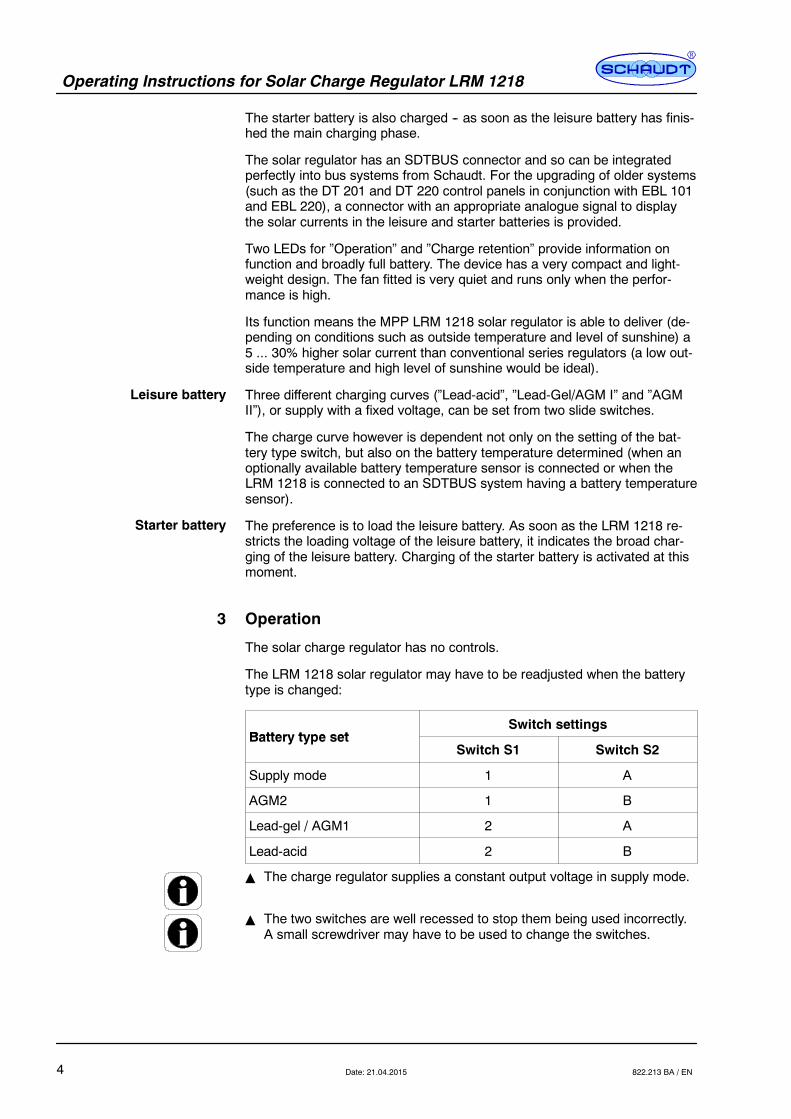
3 Operation
The solar charge regulator has no controls.
The LRM 1218 solar regulator may have to be readjusted when the batterytype is changed:
Battery type setSwitch settings
Battery type setSwitch S1 Switch S2
Supply mode 1 A
AGM2 1 B
Lead-gel / AGM1 2 A
Lead-acid 2 B
Y The charge regulator supplies a constant output voltage in supply mode.
Y The two switches are well recessed to stop them being used incorrectly.A small screwdriver may have to be used to change the switches.
Leisure battery
Starter battery
Operating Instructions for Solar Charge Regulator LRM 1218
5Date: 21.04.2015822.213 BA / EN
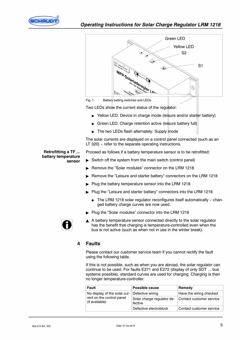
S2
S1
Green LED
Yellow LED
Fig. 1 Battery setting switches and LEDs
Two LEDs show the current status of the regulator:
F Yellow LED: Device in charge mode (leisure and/or starter battery)
F Green LED: Charge retention active (leisure battery full)
F The two LEDs flash alternately: Supply mode
The solar currents are displayed on a control panel connected (such as anLT 320) -- refer to the separate operating instructions.
Proceed as follows if a battery temperature sensor is to be retrofitted:
" Switch off the system from the main switch (control panel)
" Remove the ”Solar modules” connector on the LRM 1218
" Remove the ”Leisure and starter battery” connectors on the LRM 1218
" Plug the battery temperature sensor into the LRM 1218
" Plug the ”Leisure and starter battery” connectors into the LRM 1218
F The LRM 1218 solar regulator reconfigures itself automatically -- chan-ged battery charge curves are now used.
" Plug the ”Solar modules” connector into the LRM 1218
Y A battery temperature sensor connected directly to the solar regulatorhas the benefit that charging is temperature-controlled even when thebus is not active (such as when not in use in the winter break).
4 Faults
Please contact our customer service team if you cannot rectify the faultusing the following table.
If this is not possible, such as when you are abroad, the solar regulator cancontinue to be used. For faults E271 and E272 (display of only SDT ... bussystems possible), standard curves are used for charging. Charging is thenno longer temperature-controller.
Fault Possible cause Remedy
No display of the solar cur- Defective wiring Have the wiring checkedp yrent on the control panel(if available)
Solar charge regulator de-fective
Contact customer service
Defective electroblock Contact customer service
Retrofitting a TF ...battery temperature
sensor

Operating Instructions for Solar Charge Regulator LRM 1218
6 Date: 21.04.2015 822.213 BA / EN
Fault RemedyPossible cause
Batteries are not being Defective batteries Have the batteries checkedgcharged If batteries are in perfect
working order: Solarcharge regulator defective
Contact customer service
Defective electroblock Contact customer service
Defective wiring Have the wiring checked
Yellow LED flashing Output stage disabled (re-gulator not being used)due to overcurrent or over-voltage
Incorrect solar module (ortoo many solar modules)connected (input powertoo high) -- contact custo-mer service
SDT ... bus systemfault messages:
E270 No LRM 1218 on bus Check bus wiringContact customer service
E271 Battery temperature sen-sor short-circuit*
Check wiring/connectorContact customer service
E272 Battery temperature sen-sor cable break or defec-tive sensor*
Check wiringReplace sensor
E273 Overload/overcurrent and/or overtemperature
Incorrect solar module (ortoo many solar modules)connected (input powertoo high) -- contact custo-mer service
*The temperature value available on the bus is used as an alternative for bus sy-stems with another battery temperature sensor (such as a HELLA battery sensor).
5 Technical details
5.1 Mechanical details
135 x 48 x 90 (W x H x D in mm)
360 g
Plastic, blue (RAL 5010)
5.2 Electrical details
12 V DC
Up to 20 A for leisure and starter battery together;leisure battery has priority;e.g. only leisure battery for solar power 275 W:
F 20 A @ 13.2 V leisure battery voltage
F 18 A @ 14.4 V leisure battery voltage
6-cell lead batteries, 55 Ah and above (lead-acid, lead-gel, AGM)
F 36-cell modules as a minimum
F Off-load voltage 20 ... 32 V
F Maximum total capacity of solar modules 275 Wp
Dimensions
Weight
Casing
Nominal voltage
Charging current
Suitable batteries
Suitable solar modules
Operating Instructions for Solar Charge Regulator LRM 1218
7Date: 21.04.2015822.213 BA / EN
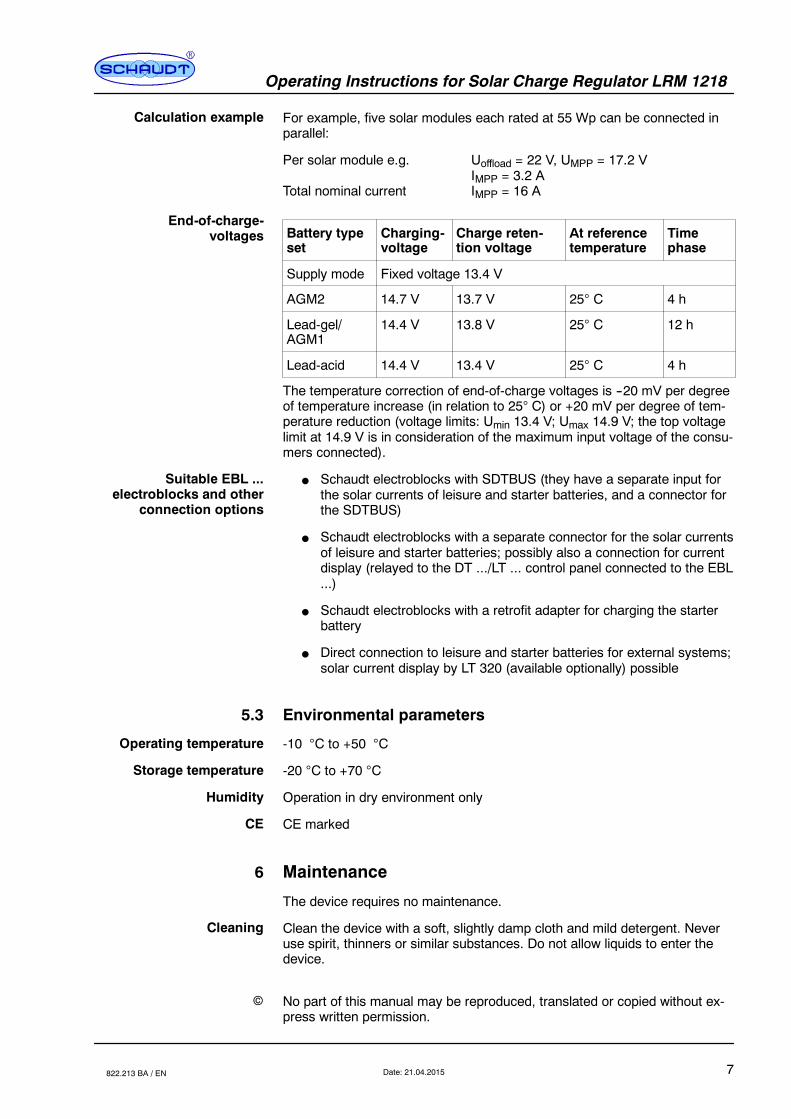
For example, five solar modules each rated at 55 Wp can be connected inparallel:
Per solar module e.g. Uoffload = 22 V, UMPP = 17.2 VIMPP = 3.2 A
Total nominal current IMPP = 16 A
Battery typeset
Charging-voltage
Charge reten-tion voltage
At referencetemperature
Timephase
Supply mode Fixed voltage 13.4 V
AGM2 14.7 V 13.7 V 25 C 4 h
Lead-gel/AGM1
14.4 V 13.8 V 25 C 12 h
Lead-acid 14.4 V 13.4 V 25 C 4 h
The temperature correction of end-of-charge voltages is --20 mV per degreeof temperature increase (in relation to 25 C) or +20 mV per degree of tem-perature reduction (voltage limits: Umin 13.4 V; Umax 14.9 V; the top voltagelimit at 14.9 V is in consideration of the maximum input voltage of the consu-mers connected).
F Schaudt electroblocks with SDTBUS (they have a separate input forthe solar currents of leisure and starter batteries, and a connector forthe SDTBUS)
F Schaudt electroblocks with a separate connector for the solar currentsof leisure and starter batteries; possibly also a connection for currentdisplay (relayed to the DT .../LT ... control panel connected to the EBL...)
F Schaudt electroblocks with a retrofit adapter for charging the starterbattery
F Direct connection to leisure and starter batteries for external systems;solar current display by LT 320 (available optionally) possible
5.3 Environmental parameters
-10 C to +50 C
-20 C to +70 C
Operation in dry environment only
CE marked
6 Maintenance
The device requires no maintenance.
Clean the device with a soft, slightly damp cloth and mild detergent. Neveruse spirit, thinners or similar substances. Do not allow liquids to enter thedevice.
No part of this manual may be reproduced, translated or copied without ex-press written permission.
Calculation example
End-of-charge-voltages
Suitable EBL ...electroblocks and other
connection options
Operating temperature
Storage temperature
Humidity
CE
Cleaning
E
Operating Instructions for Solar Charge Regulator LRM 1218
8 Date: 21.04.2015 822.213 BA / EN
Appendix
A EC Declaration of Conformity
Schaudt GmbH hereby confirms that the design of the LRM 1218 solar char-ger regulator complies with the following relevant regulations:
The original CE declaration of conformity is available for reference at anytime.
Schaudt GmbH, Elektrotechnik & Apparatebau
Daimlerstraße 588677 MarkdorfGermany
B Special fittings/accessories
LT 320 instrument panel for connection to systems without a direct solar cur-rent display by the control panel
TF 50 A battery sensor to read the battery temperature -- is read automati-cally and has a bearing on the charging characteristics
C Fault report
In the event of damage, please fill in the fault report and send it with thefaulty device to the manufacturer.
Device type: _______________________Item no.: _______________________Vehicle: Manufacturer: _______________________
Model: _______________________Own installation? Yes - No-Upgrade? Yes - No-
Following fault has occurred (please tick):
- Battery is not charged when solar modules are connected- Persistent fault- Intermittent fault/loose contact
Other comments:
Manufacturer
Address
Panel
Battery temperaturesensor
Operating Instructions for Solar Charge Regulator LRM 1218
9Date: 21.04.2015822.213 BA / EN
D Customer service
Schaudt GmbH, Elektrotechnik & ApparatebauPlanckstraße 888677 Markdorf, Germany
Phone: +49 7544 9577-16 Email: [email protected]
Office hours Mon to Thurs 08.00 -- 12.00, 13.00 -- 16.00Fri 08.00 -- 12.00
Returning a faulty device:
" Complete and enclose the fault report, see Appendix C.
" Send it to the addressee (free delivery).
E Mechanical layout
1
3
7.5
130.7
90
119
60
ø4 (2x)
135
48
2
3 4 5
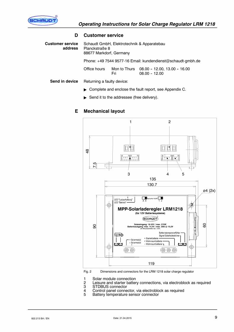
Fig. 2 Dimensions and connectors for the LRM 1218 solar charge regulator
1 Solar module connection2 Leisure and starter battery connections, via electroblock as required3 STDBUS connector4 Control panel connector, via electroblock as required5 Battery temperature sensor connector
Customer serviceaddress
Send in device
Operating Instructions for Solar Charge Regulator LRM 1218
10 Date: 21.04.2015 822.213 BA / EN
(blank page)
Date: 21.04.2015
E Schaudt GmbH, Elektrotechnik und Apparatebau, Planckstraße 8, 88677 Markdorf, Germany, Tel. +49 7544 9577-0, Fax +49 7544 9577-29, www.schaudt--gmbh.de
822.213 BA / EN
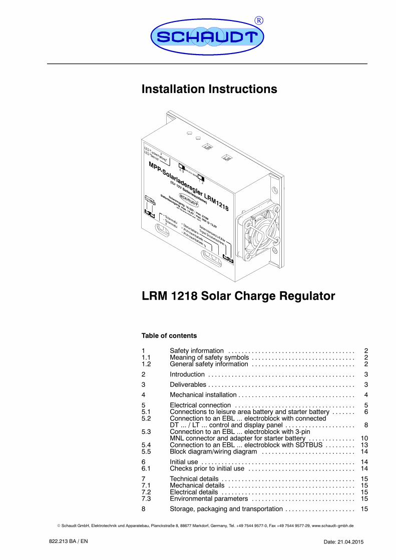
Installation Instructions
LRM 1218 Solar Charge Regulator
Table of contents
1 Safety information 2. . . . . . . . . . . . . . . . . . . . . . . . . . . . . . . . . . . . . .1.1 Meaning of safety symbols 2. . . . . . . . . . . . . . . . . . . . . . . . . . . . . . .1.2 General safety information 2. . . . . . . . . . . . . . . . . . . . . . . . . . . . . . .
2 Introduction 3. . . . . . . . . . . . . . . . . . . . . . . . . . . . . . . . . . . . . . . . . . . .
3 Deliverables 3. . . . . . . . . . . . . . . . . . . . . . . . . . . . . . . . . . . . . . . . . . . .
4 Mechanical installation 4. . . . . . . . . . . . . . . . . . . . . . . . . . . . . . . . . . .
5 Electrical connection 5. . . . . . . . . . . . . . . . . . . . . . . . . . . . . . . . . . . .5.1 Connections to leisure area battery and starter battery 6. . . . . . .5.2 Connection to an EBL ... electroblock with connected
DT ... / LT ... control and display panel 8. . . . . . . . . . . . . . . . . . . . .5.3 Connection to an EBL ... electroblock with 3-pin
MNL connector and adapter for starter battery 10. . . . . . . . . . . . . .5.4 Connection to an EBL ... electroblock with SDTBUS 13. . . . . . . . .5.5 Block diagram/wiring diagram 14. . . . . . . . . . . . . . . . . . . . . . . . . . . .
6 Initial use 14. . . . . . . . . . . . . . . . . . . . . . . . . . . . . . . . . . . . . . . . . . . . . .6.1 Checks prior to initial use 14. . . . . . . . . . . . . . . . . . . . . . . . . . . . . . . .
7 Technical details 15. . . . . . . . . . . . . . . . . . . . . . . . . . . . . . . . . . . . . . . .7.1 Mechanical details 15. . . . . . . . . . . . . . . . . . . . . . . . . . . . . . . . . . . . . .7.2 Electrical details 15. . . . . . . . . . . . . . . . . . . . . . . . . . . . . . . . . . . . . . . .7.3 Environmental parameters 15. . . . . . . . . . . . . . . . . . . . . . . . . . . . . . .
8 Storage, packaging and transportation 15. . . . . . . . . . . . . . . . . . . . .
Installation instructions for solar charge regulator LRM 1218
2 Date: 21.04.2015 822.213 MA / EN
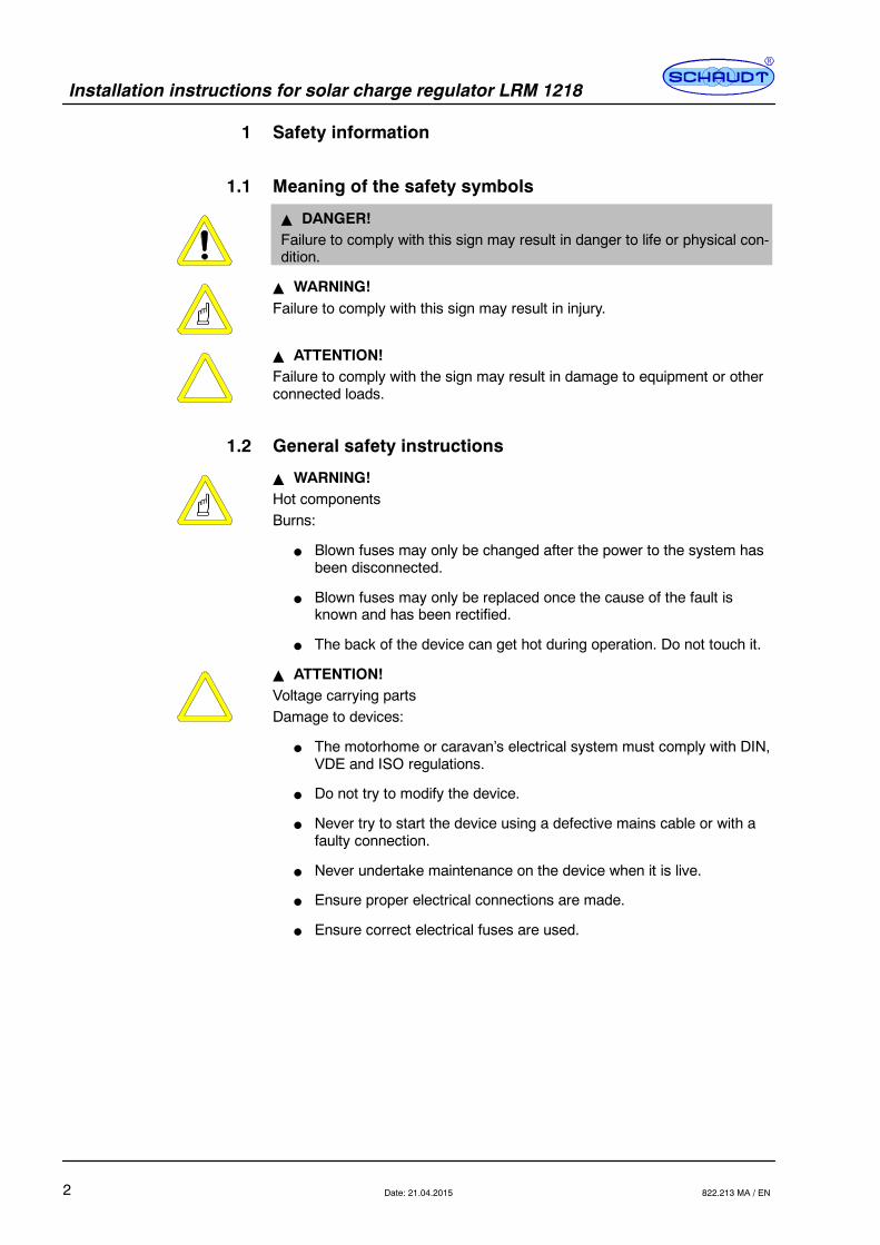
1 Safety information
1.1 Meaning of the safety symbols
Y DANGER!Failure to comply with this sign may result in danger to life or physical con-dition.
Y WARNING!Failure to comply with this sign may result in injury.
Y ATTENTION!Failure to comply with the sign may result in damage to equipment or otherconnected loads.
1.2 General safety instructions
Y WARNING!Hot componentsBurns:
F Blown fuses may only be changed after the power to the system hasbeen disconnected.
F Blown fuses may only be replaced once the cause of the fault isknown and has been rectified.
F The back of the device can get hot during operation. Do not touch it.
Y ATTENTION!Voltage carrying partsDamage to devices:
F The motorhome or caravan’s electrical system must comply with DIN,VDE and ISO regulations.
F Do not try to modify the device.
F Never try to start the device using a defective mains cable or with afaulty connection.
F Never undertake maintenance on the device when it is live.
F Ensure proper electrical connections are made.
F Ensure correct electrical fuses are used.

Installation instructions for solar charge regulator LRM 1218
3Date: 21.04.2015822.213 MA / EN
2 Introduction
These installation instructions are aimed at trained personnel.
They contain important information on the connection and safe operation ofthe device. The safety information provided must be observed.
Always follow the relevant instruction manual in addition to the installationinstructions.
3 Deliverables
Delivered as part of the LRM 1218 solar charge regulator:
F 1 x LRM 1218 solar charge regulator
F Connector set (small parts and connector cables) for the differentapplications
F Operating instructions
F Installation instructions
1
2
3 4 5
7 6
Fig. 1 Small parts and accessories delivered with the LRM 1218 solar charge regulator
Pos. Qty Name1 2 Flat vehicle fuse, 20A2 1 Flat vehicle fuse, 15 A3 2 Fuse holder for flat vehicle fuse4 5 Flat push--on contacts, 6.3 x 0.8 without sleeve5 2 Screws, 3.5 x 206 6 Flat push--on contacts, 6.3 x 0.8 (blue)7 4 Insulating sleeves for pos. 4
Installation instructions for solar charge regulator LRM 1218
4 Date: 21.04.2015 822.213 MA / EN
1
2
3
12
32
31
4
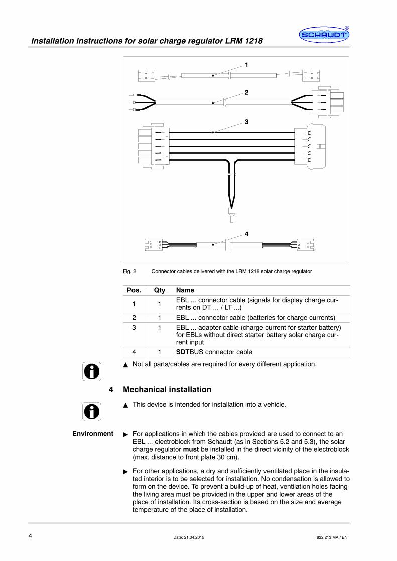
Fig. 2 Connector cables delivered with the LRM 1218 solar charge regulator
Pos. Qty Name
1 1 EBL ... connector cable (signals for display charge cur-rents on DT ... / LT ...)
2 1 EBL ... connector cable (batteries for charge currents)3 1 EBL ... adapter cable (charge current for starter battery)
for EBLs without direct starter battery solar charge cur-rent input
4 1 SDTBUS connector cable
Y Not all parts/cables are required for every different application.
4 Mechanical installation
Y This device is intended for installation into a vehicle.
" For applications in which the cables provided are used to connect to anEBL ... electroblock from Schaudt (as in Sections 5.2 and 5.3), the solarcharge regulator must be installed in the direct vicinity of the electroblock(max. distance to front plate 30 cm).
" For other applications, a dry and sufficiently ventilated place in the insula-ted interior is to be selected for installation. No condensation is allowed toform on the device. To prevent a build-up of heat, ventilation holes facingthe living area must be provided in the upper and lower areas of theplace of installation. Its cross-section is based on the size and averagetemperature of the place of installation.
Environment
Installation instructions for solar charge regulator LRM 1218
5Date: 21.04.2015822.213 MA / EN
" Ensure a minimum clearance to the surrounding fixtures and fittings:
F Maintain a gap of at least 5 cm on all sides (except mounted side).
F Whilst in operation, the ambient temperature must not exceed +45 C,measured 2.5 cm away from the sides of the device.
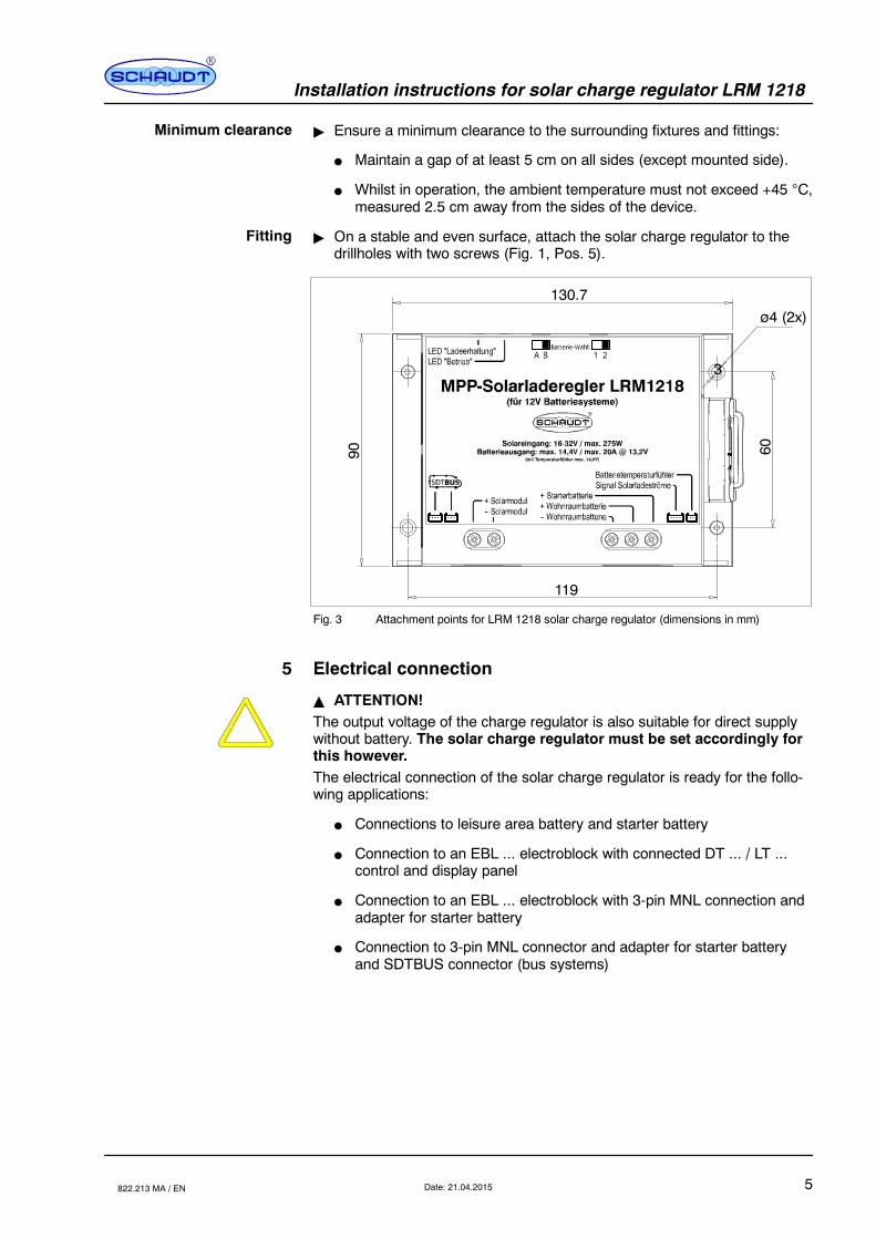
" On a stable and even surface, attach the solar charge regulator to thedrillholes with two screws (Fig. 1, Pos. 5).
3
130.7
90
119
60
ø4 (2x)
Fig. 3 Attachment points for LRM 1218 solar charge regulator (dimensions in mm)
5 Electrical connection
Y ATTENTION!The output voltage of the charge regulator is also suitable for direct supplywithout battery. The solar charge regulator must be set accordingly forthis however.The electrical connection of the solar charge regulator is ready for the follo-wing applications:
F Connections to leisure area battery and starter battery
F Connection to an EBL ... electroblock with connected DT ... / LT ...control and display panel
F Connection to an EBL ... electroblock with 3-pin MNL connection andadapter for starter battery
F Connection to 3-pin MNL connector and adapter for starter batteryand SDTBUS connector (bus systems)
Minimum clearance
Fitting
Installation instructions for solar charge regulator LRM 1218
6 Date: 21.04.2015 822.213 MA / EN
5.1 Connections to leisure area battery and starter battery
Y ATTENTION!Short circuits!Damage to the solar charge regulator or fire damage to cable:
F To protect the supply lines in the event of a short circuit, connect thefuses directly to the positive pole of battery.
Select cable cross-sections in line with EN 1648-1/-2. The maximum currentload must not exceed 90% of the individual fuse rating.
Recommended cable cross-sections:
Line length(sum of supply and return lines)
Cable cross-section
Up to 4 m 2,5 mm2
Up to 8 m 4,0 mm2
Up to 12 m 6,0 mm2
For this application, the follow parts are required from those delivered:
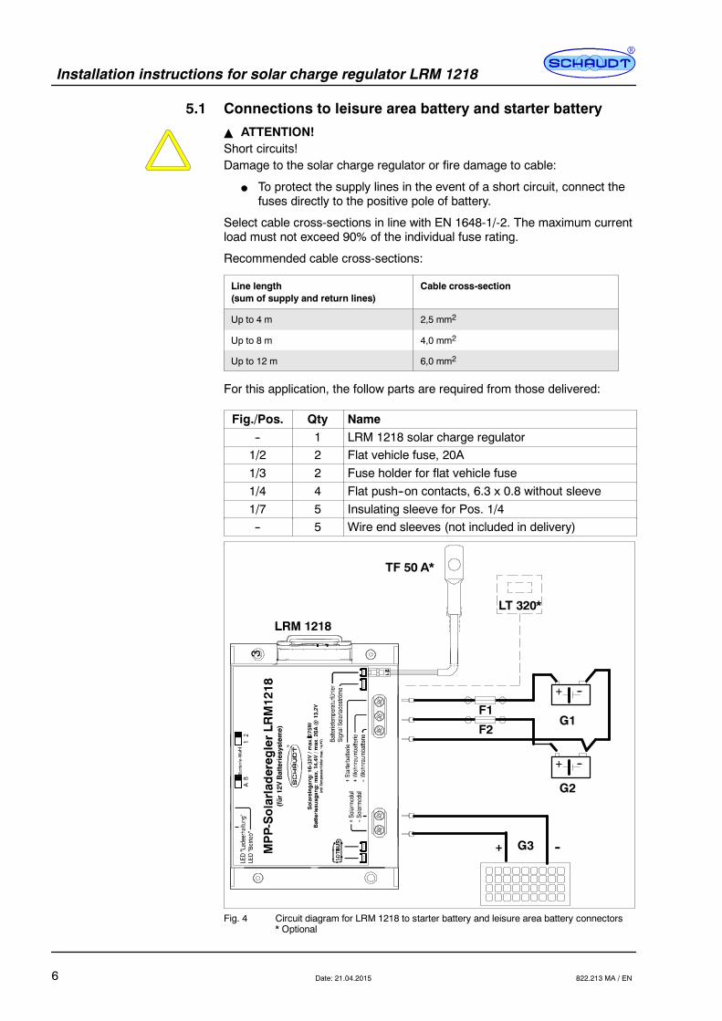
Fig./Pos. Qty Name-- 1 LRM 1218 solar charge regulator1/2 2 Flat vehicle fuse, 20A1/3 2 Fuse holder for flat vehicle fuse1/4 4 Flat push--on contacts, 6.3 x 0.8 without sleeve1/7 5 Insulating sleeve for Pos. 1/4-- 5 Wire end sleeves (not included in delivery)
+ --
+ --
F1
F2G1
G2
G3
--
--+
LRM 1218
3
LT 320*
TF 50 A*
Fig. 4 Circuit diagram for LRM 1218 to starter battery and leisure area battery connectors* Optional

Installation instructions for solar charge regulator LRM 1218
7Date: 21.04.2015822.213 MA / EN
Pos. NameF1 Fuse for starter battery charge current (20A)F2 Fuse for leisure area battery charge current (20A)G1 Starter batteryG2 Leisure batteryG3 Solar module(s)
LRM 1218 Solar charge regulatorLT320* Control panel solar charge currents (optional special configura-
tion; cable delivered with the panel)
TF 50 A* Temperature sensor (special configuration, see also Section5.5)
Establish the connection on the side of the solar charge regulator in the fol-lowing order:
" 1. Connect the two fuse holders with fuses to the connection cable in ac-cordance with the circuit diagram in Fig. 4. Use the flat push--on con-tacts (6.3 x 0.8) without sleeve for this (Fig. 1, Pos. 5). After crimping,attach the insulating sleeves (Fig. 1, Pos. 7). Insert the two fuses.
" 2. First connect the connection cables for living area battery and starterbattery to the solar charge regulator, observing the polarity of the con-nections. Use wire end sleeves for this (not included in the delivery).
" 3. Connect the cables for leisure area battery and starter battery to thebatteries.
" 4. Finally, connect solar modules to the solar charge regulator. Use wireend sleeves for this (not included in the delivery).
Y Steps 5. ... 9. ONLY when a TF 50 A temperature sensor is fitted (optio-nal):
" 5 Clamp the TF 50 A battery sensor to one of the terminals (preferablethe negative terminal) of the leisure area battery (note: this is NOT anelectrical connection -- only the temperature of the battery terminal isread with this mechanical connection; this is virtually identical to theinternal temperature of the battery)
" 6. Guide the cable through the vehicle to the LRM 1218 solar chargeregulator.
" 7. Plug the TF 50 A battery sensor connector into the LRM 1218 solarcharge regulator.
" 8. Secure the battery sensor cable at a suitable place (particularly nearthe connector on the LRM 1218 to prevent the 2-pin connector fromcoming loose).
" 9. Unplug the ”Solar modules” and ”Leisure area and starter batteries”connectors from the LRM 1218 and plug them back in again after 30seconds. This ”registers” the sensor.
Disconnect in the reverse order.
Connection sequence
Disconnection

Installation instructions for solar charge regulator LRM 1218
8 Date: 21.04.2015 822.213 MA / EN
5.2 Connection to an EBL ... electroblock with connectedDT ... / LT ... control and display panel
For this application, the follow parts are required from those delivered:
Fig./Pos. Qty Name1 1 LRM 1218 solar charge regulator
1/1 or 2 1 20A or 15A flat vehicle fuse (depending on EBL ...)
2/1 1 EBL ... connector cable (signals for display chargecurrents on DT ... / LT ...)
2/2 1 EBL ... connector cable (batteries for charge cur-rents)
-- 2 Wire end sleeves (not included in delivery)
G3
+
--
--+
LRM 1218
3
RedBlack
Brown
White
Brown
EBL ...on block”Solar charge
EBL ...on block”Solar charge
X
Y
TF 50 A*
regulator”
regulator”
Fig. 5 Circuit diagram for LRM 1218 connection to EBLs with solar regulator connectorand connector for current display (* optional)
Installation instructions for solar charge regulator LRM 1218
9Date: 21.04.2015822.213 MA / EN
Pos. NameX Cable with electroblock connector:
-- X1 Brown Negative battery-- X2 Red + Starter battery-- X3 Black + Leisure area battery
Y Cable with DT .../LT ... control and display panel connector-- Y1 Brown Leisure area battery signal-- Y2 White Starter battery signal
G3 Solar module(s)LRM 1218 Solar charge regulatorTF 50 A* Temperature sensor (special configuration, see also Section
5.5)
Establish the connection on the front of the solar charge regulator in the fol-lowing order:
" 1. Connect the electroblock with cable X (connection cable EBL ...(charge currents for batteries), Fig. 2, Pos. 2).
" 2. Connect the electroblock with cable Y (signals for display of chargecurrents on DT ... / LT ..., Fig. 2, Pos. 1).
" 3. Fit the right flat vehicle fuse (15A or 20 A; Fig. 1, Pos. 1 or 2) into the”Solar” fuse on the EBL ...
" 4. Finally, connect solar modules to the solar charge regulator. Use wireend sleeves for this.
Y The correct fuse rating is printed on the front plate of the EBL... electro-block. See also the block diagram in the operating instructions for theelectroblock.
Y Steps 5. ... 9. ONLY when a TF 50 A temperature sensor is fitted (optio-nal):
" 5 Clamp the TF 50 A battery sensor to one of the terminals (preferablethe negative terminal) of the leisure area battery (note: this is NOT anelectrical connection -- only the temperature of the battery terminal isread with this mechanical connection; this is virtually identical to theinternal temperature of the battery)
" 6. Guide the cable through the vehicle to the LRM 1218 solar chargeregulator
" 7. Plug the TF 50 A battery sensor connector into the LRM 1218 solarcharge regulator
" 8. Secure the battery sensor cable at a suitable place (particularly nearthe connector on the LRM 1218 to prevent the 2-pin connector fromcoming loose)
" 9. Unplug the ”Solar modules” and ”Leisure area and starter batteries”connectors from the LRM 1218 and plug them back in again after 30seconds. This ”registers” the sensor.
Disconnect in the reverse order.
Connection sequence
Disconnection

Installation instructions for solar charge regulator LRM 1218
10 Date: 21.04.2015 822.213 MA / EN
5.3 Connection to an EBL ... electroblock with 3--pin MNL con-nection and adapter for starter battery
When using an electroblock which only has a 3--pin connection for a solarcharge regulator, an adapter for charging the starter battery can be retrofit-ted. It is then possible to charge the leisure area and starter batteries simul-taneously.
The following electroblocks (as of April 2008) can be used with the adapter:
F EBL 99F EBL 100F EBL 264-9F EBL 240F EBL 269
An LT 320 operating and display panel, for the display of solar charge cur-rents, can be used as an optional accessory.
For this application, the follow parts are required from those delivered:
Fig./Pos. Qty Name1 1 LRM 1218 solar charge regulator
1/1 or 2 1 20A or 15A flat vehicle fuse (depending on EBL ...)2/2 1 EBL ... connector cable (leisure area battery charge
current). Here the middle wire on the connectormust be detached and the red cable be pulled fromthe insulating sleeve.
2/3 1 EBL ... connector cable (starter battery charge cur-rents) is looped in between cable loom and EBL
-- 2 Wire end sleeves (not included in delivery)

Installation instructions for solar charge regulator LRM 1218
11Date: 21.04.2015822.213 MA / EN
G3
+
--
--+
LRM 1218
3BlackBrown
EBL ...on block”Solar charge
X
Ya Yb
2 x Red
EBL ...on block
Cable loom
LT 320*
BlackBrownYellowBrown
Red Red
TF 50 A*
regulator”
Fig. 6 Circuit diagram for LRM 1218 connection to EBL ...
Pos. NameX Cable with electroblock connector:
-- X1 Brown Negative battery-- X2 -- Not assigned (detach red cable on connector
and remove from insulation sleeve)-- X3 Black + Leisure area battery
Y Electroblock adapter cable-- Ya To available electroblock cable-- Yb To electroblock-- Y1 Red + Starter battery-- Y2 Brown Negative sensor, leisure area battery-- Y3 yellow D+ input-- Y4 Brown Negative starter battery for refrigerator-- Y5 Black + Leisure area battery sensor
G3 Solar module(s)LRM 1218 Solar charge regulatorLT320* Control panel solar charge currents (optional special configu-
ration; cable delivered with the panel)
TF 50 A* Temperature sensor (special configuration, see also Section5.5)
Installation instructions for solar charge regulator LRM 1218
12 Date: 21.04.2015 822.213 MA / EN
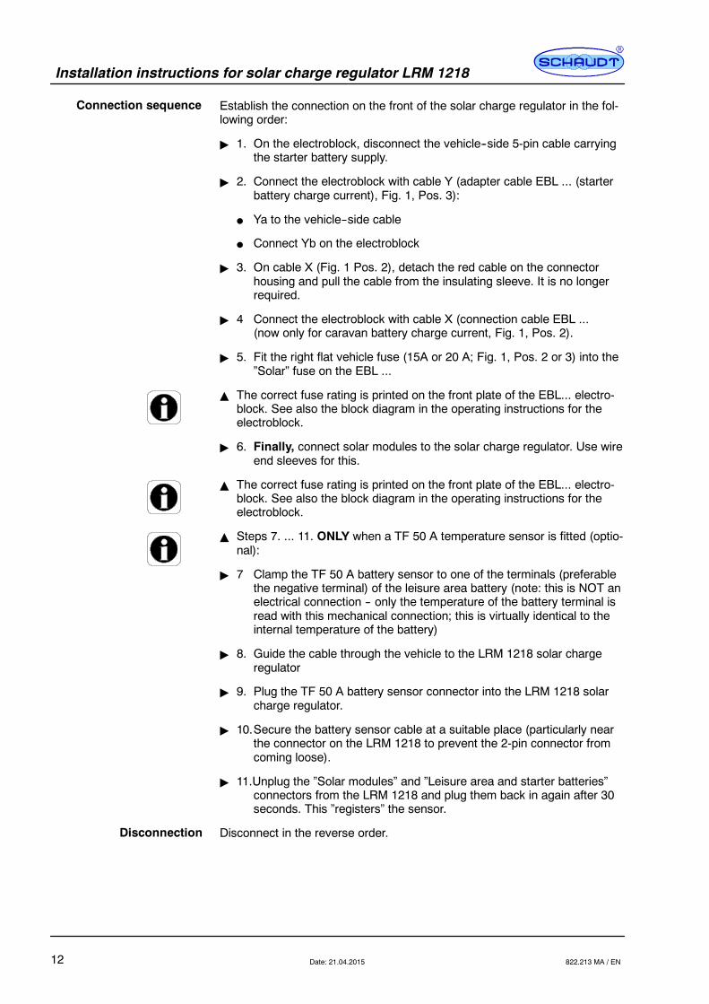
Establish the connection on the front of the solar charge regulator in the fol-lowing order:
" 1. On the electroblock, disconnect the vehicle--side 5-pin cable carryingthe starter battery supply.
" 2. Connect the electroblock with cable Y (adapter cable EBL ... (starterbattery charge current), Fig. 1, Pos. 3):
F Ya to the vehicle--side cable
F Connect Yb on the electroblock
" 3. On cable X (Fig. 1 Pos. 2), detach the red cable on the connectorhousing and pull the cable from the insulating sleeve. It is no longerrequired.
" 4 Connect the electroblock with cable X (connection cable EBL ...(now only for caravan battery charge current, Fig. 1, Pos. 2).
" 5. Fit the right flat vehicle fuse (15A or 20 A; Fig. 1, Pos. 2 or 3) into the”Solar” fuse on the EBL ...
Y The correct fuse rating is printed on the front plate of the EBL... electro-block. See also the block diagram in the operating instructions for theelectroblock.
" 6. Finally, connect solar modules to the solar charge regulator. Use wireend sleeves for this.
Y The correct fuse rating is printed on the front plate of the EBL... electro-block. See also the block diagram in the operating instructions for theelectroblock.
Y Steps 7. ... 11. ONLY when a TF 50 A temperature sensor is fitted (optio-nal):
" 7 Clamp the TF 50 A battery sensor to one of the terminals (preferablethe negative terminal) of the leisure area battery (note: this is NOT anelectrical connection -- only the temperature of the battery terminal isread with this mechanical connection; this is virtually identical to theinternal temperature of the battery)
" 8. Guide the cable through the vehicle to the LRM 1218 solar chargeregulator
" 9. Plug the TF 50 A battery sensor connector into the LRM 1218 solarcharge regulator.
" 10.Secure the battery sensor cable at a suitable place (particularly nearthe connector on the LRM 1218 to prevent the 2-pin connector fromcoming loose).
" 11.Unplug the ”Solar modules” and ”Leisure area and starter batteries”connectors from the LRM 1218 and plug them back in again after 30seconds. This ”registers” the sensor.
Disconnect in the reverse order.
Connection sequence
Disconnection
Installation instructions for solar charge regulator LRM 1218
13Date: 21.04.2015822.213 MA / EN
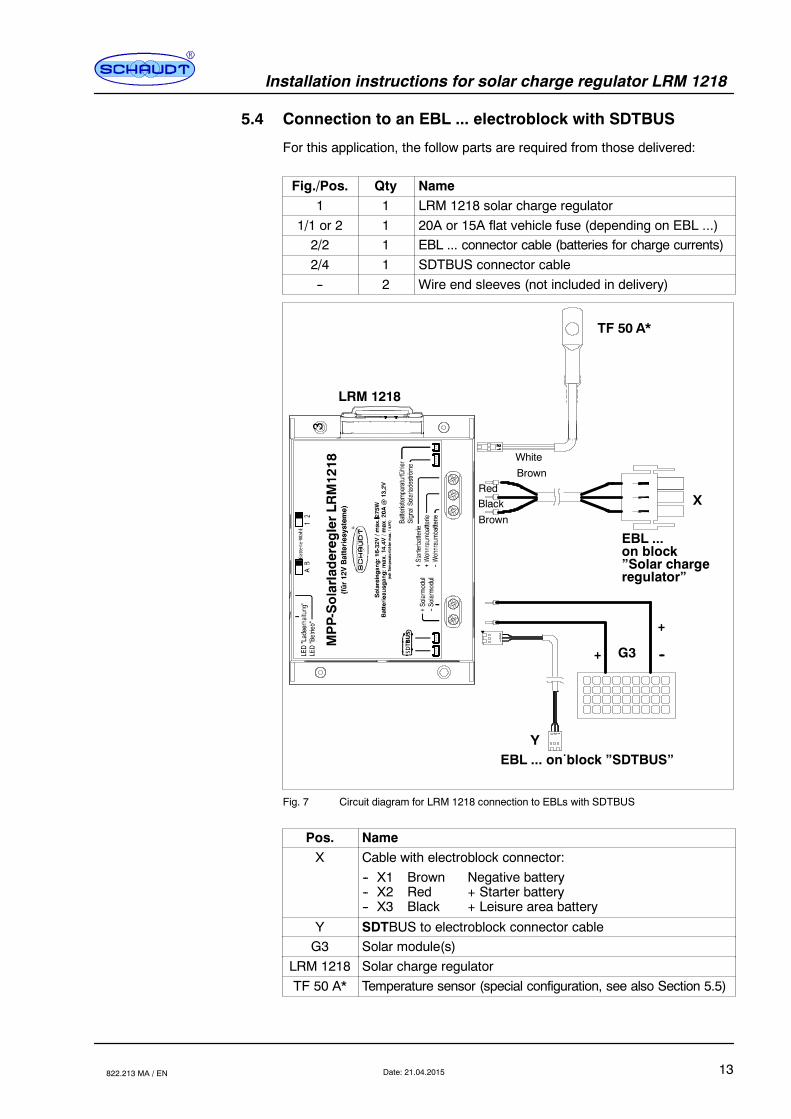
5.4 Connection to an EBL ... electroblock with SDTBUS
For this application, the follow parts are required from those delivered:
Fig./Pos. Qty Name1 1 LRM 1218 solar charge regulator
1/1 or 2 1 20A or 15A flat vehicle fuse (depending on EBL ...)2/2 1 EBL ... connector cable (batteries for charge currents)2/4 1 SDTBUS connector cable-- 2 Wire end sleeves (not included in delivery)
G3
+
--
--+
LRM 1218
3TF 50 A*
RedBlack
Brown
White
Brown
EBL ...on block”Solar charge
EBL ... on block ”SDTBUS”
X
Y
12
3 2
3
1
regulator”
Fig. 7 Circuit diagram for LRM 1218 connection to EBLs with SDTBUS
Pos. NameX Cable with electroblock connector:
-- X1 Brown Negative battery-- X2 Red + Starter battery-- X3 Black + Leisure area battery
Y SDTBUS to electroblock connector cableG3 Solar module(s)
LRM 1218 Solar charge regulatorTF 50 A* Temperature sensor (special configuration, see also Section 5.5)
Installation instructions for solar charge regulator LRM 1218
14 Date: 21.04.2015 822.213 MA / EN
Establish the connection on the front of the solar charge regulator in thefollowing order:
" 1. Connect the electroblock with cable X (connection cable EBL ...(charge currents for batteries), Fig. 2, Pos. 2).
" 2. Connect the electroblock with cable Y (SDTBUS, Fig. 2, Pos. 4).
" 3. Fit the right flat vehicle fuse (15A or 20 A; Fig. 1, Pos. 1 or 2) into the”Solar” fuse on the EBL ...
" 4. Finally, connect solar modules to the solar charge regulator. Use wireend sleeves for this.
Y The correct fuse rating is printed on the front plate of the EBL... electro-block. See also the block diagram in the operating instructions for theelectroblock.
Y Steps 5. ... 9. ONLY when a TF 50 A temperature sensor is fitted (optio-nal):
" 5 Clamp the TF 50 A battery sensor to one of the terminals (preferablethe negative terminal) of the leisure area battery (note: this is NOT anelectrical connection -- only the temperature of the battery terminal isread with this mechanical connection; this is virtually identical to theinternal temperature of the battery).
" 6. Guide the cable through the vehicle to the LRM 1218 solar chargeregulator.
" 7. Plug the TF 50 A battery sensor connector into the LRM 1218 solarcharge regulator.
" 8. Secure the battery sensor cable at a suitable place (particularly nearthe connector on the LRM 1218 to prevent the 2-pin connector fromcoming loose).
" 9. Unplug the ”Solar modules” and ”Leisure area and starter batteries”connectors from the LRM 1218 and plug them back in again after 30seconds. This ”registers” the sensor.
Disconnect in the reverse order.
5.5 TF 50 A battery temperature sensor (optional)
The optional TF 50 A battery temperature sensor is used to implement bat-tery temperature--controlled charging. The LRM 1218 solar regulator mustbe fully isolated from the power for the sensor to be detected (unplug theconnectors for solar modules and batteries, and plug them in again after 30seconds).
A battery temperature sensor can also be ”deregistered” by first unpluggingthe connectors for solar modules and batteries on the LRM 1218, and thendisconnecting the temperature sensor.
Once the connectors for solar modules and batteries are plugged in again,the sensor is ”deregistered” and no faults are displayed (bus system).
6 Block diagram/wiring diagram
Y The block diagram and connection diagram are appended to the instruc-tion manual of the solar charge regulator.
Connection sequence
Disconnection
Installation instructions for solar charge regulator LRM 1218
15Date: 21.04.2015822.213 MA / EN
7 Initial use
7.1 Checks prior to initial use
" Ensure that all the connections are correct (only for initial use).
" Ensure that the batteries or the electroblock are connected (dependingon operating mode).
" Connect the solar module to the solar charge regulator with the correctpolarity. The solar charge regulator is ready to use.
8 Technical details
8.1 Mechanical details
135 x 48 x 90 (W x H x D in mm)
360 g
Blue plastic (RAL 5010)
8.2 Electrical details
12 V
MPP regulator (Maximum Point Tracking)
Dependent on setting, see operating instructions table
See operating instructions
For shaded solar module:Approx. 4 mA from leisure area batteryApprox. 0.5 mA from starter battery
6-cell lead acid or lead gel batteries, rated 55 Ah or higher
F At least 36--cell modules
F Open circuit voltage 20 ... 32 V
F Maximum overall capacity of solar modules 275 Wp
8.3 Environmental parameters
-10 C to +50 C
-20 C to +70 C
Operation in dry environment only
CE marked
9 Storage, packaging and transportation
Only transport and store the solar charge regulator if the packing is suitableand ambient conditions are dry.
Before starting up
Starting up the system
Dimensions
Weight
Casing
Nominal voltage
Regulating principle
Final charge voltage
Charge current
Solar charge regulatorconsumption
Suitable batteries
Suitable solar modules
Operating temperature
Storage temperature
Humidity
CE
Installation instructions for solar charge regulator LRM 1218
16 Date: 21.04.2015 822.213 MA / EN
No part of this manual may be reproduced, translated or copied without ex-press written permission.
E


![Cantata No. 213 : Hercules auf dem Scheidewege …€¦ · Title: Cantata No. 213 : Hercules auf dem Scheidewege [BWV 213] Author: Bach, Johann Sebastian Subject: No commercial use](https://img.pdfslide.org/doc/110x75/5b79abc17f8b9a331e8e5687/cantata-no-213-hercules-auf-dem-scheidewege-title-cantata-no-213-hercules.jpg)