Embed Size (px)
Citation preview
C. Okay Aksoy Melih GenişGülsev Uyar Aldaş Vehbi ÖzacarSamet C. Özer Özgür Yılmaz
A COMPARATIVE STUDY OF THE DETERMINATION OF ROCK MASS DEFORMATION MODULUS BYUSING DIFFERENT EMPIRICAL APPROACHES
授課老師:謝平城指導教授:張光宗7100042024 陳宥序2012 . 6 . 4
1

• Introduction
•Geological and geotechnical properties
•Numerical modelling study
•Results and discussions
•Conclusions
2

Introduction
• In a rock engineering project, final design processes are very time consuming, expensive and need great experience. Feng and Hudson(2010) explained what should have been done to find how much information is needed at which of a project.
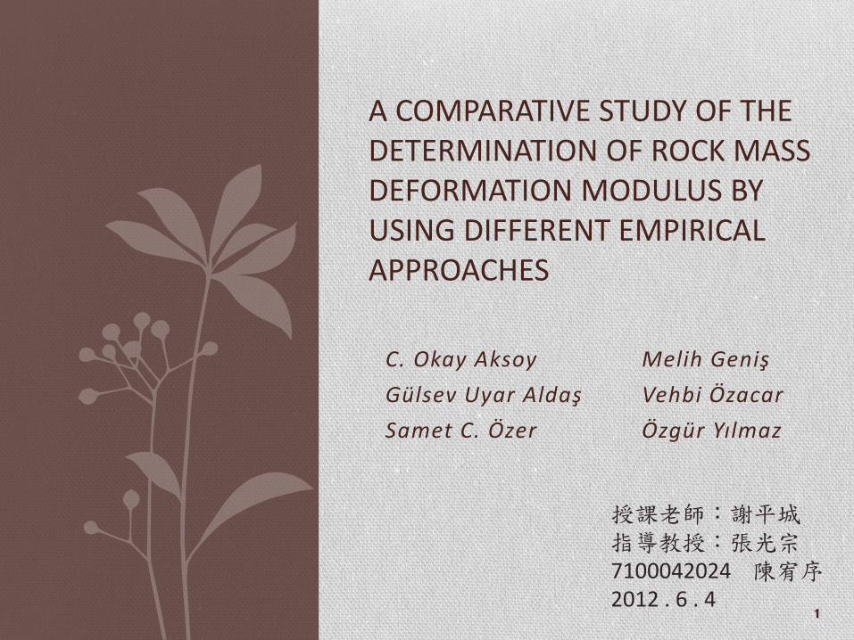
• In the beginning of the design process, definition and characterization of rock mass had to be done. For this purpose, some researchers have developed rock mass classification systems (Table 1).
3
4
• The static modulus of deformation is among the parameters that best represent the mechanical behaviourof a rock and of a rock mass, in particular when it comes to underground excavations.
• All in situ deformation tests are expensive and difficult to conduct. They are mostly conducted in special test aditsor drifts excavated by conventional drill and blast, having a span of 2 m and a height of 2.5 m using various forms of test methods.
5
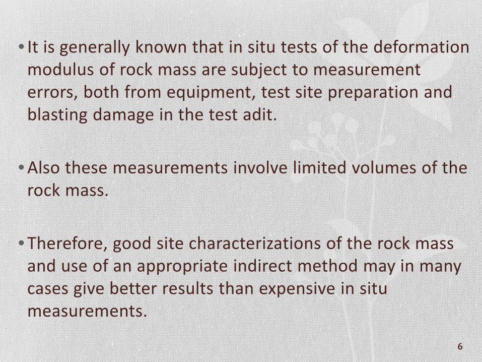
• It is generally known that in situ tests of the deformation modulus of rock mass are subject to measurement errors, both from equipment, test site preparation and blasting damage in the test adit.
• Also these measurements involve limited volumes of the rock mass.
• Therefore, good site characterizations of the rock mass and use of an appropriate indirect method may in many cases give better results than expensive in situ measurements.
6

7
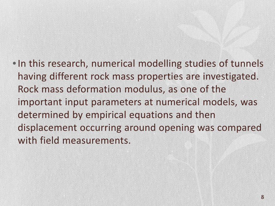
• In this research, numerical modelling studies of tunnels having different rock mass properties are investigated. Rock mass deformation modulus, as one of the important input parameters at numerical models, was determined by empirical equations and then displacement occurring around opening was compared with field measurements.
8
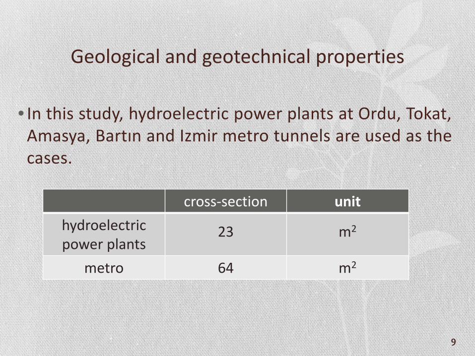
Geological and geotechnical properties
• In this study, hydroelectric power plants at Ordu, Tokat, Amasya, Bartın and Izmir metro tunnels are used as the cases.
cross-section unithydroelectric power plants
23 m2
metro 64 m2
9
10
11
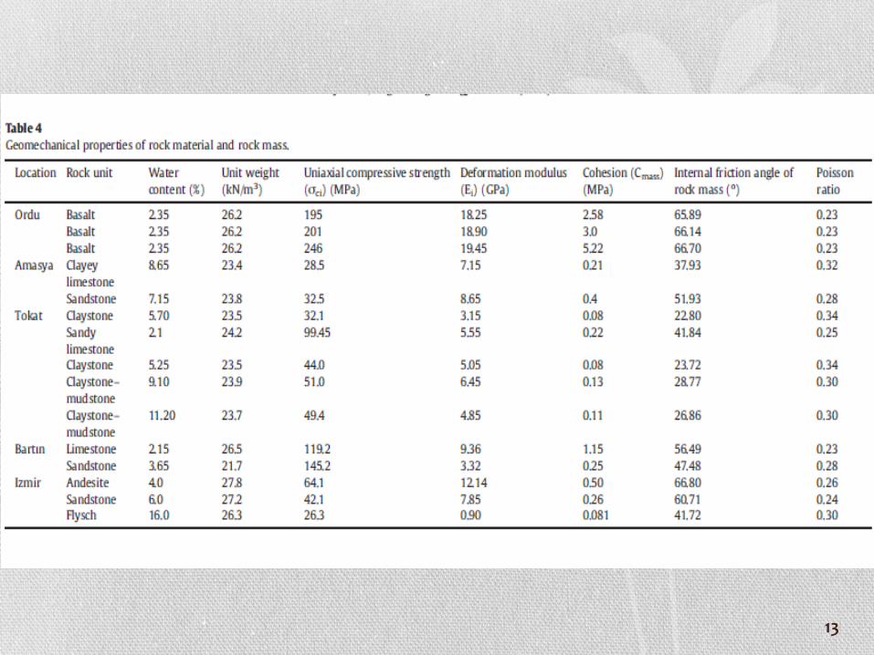
• Uniaxial compressive strength and deformation modules of intact rock are obtained from the laboratory tests in accordance with the methods suggested by ISRM, ASTM or other international standards. However, uniaxial compressive strength of rock material is determined indirectly by BPI because preparing a standard sample for uniaxial compressive strength was not possible at the Izmir metro tunnel in Bornova. Geomechanicalproperties of rock units are given in (Table 4).
12
13
14
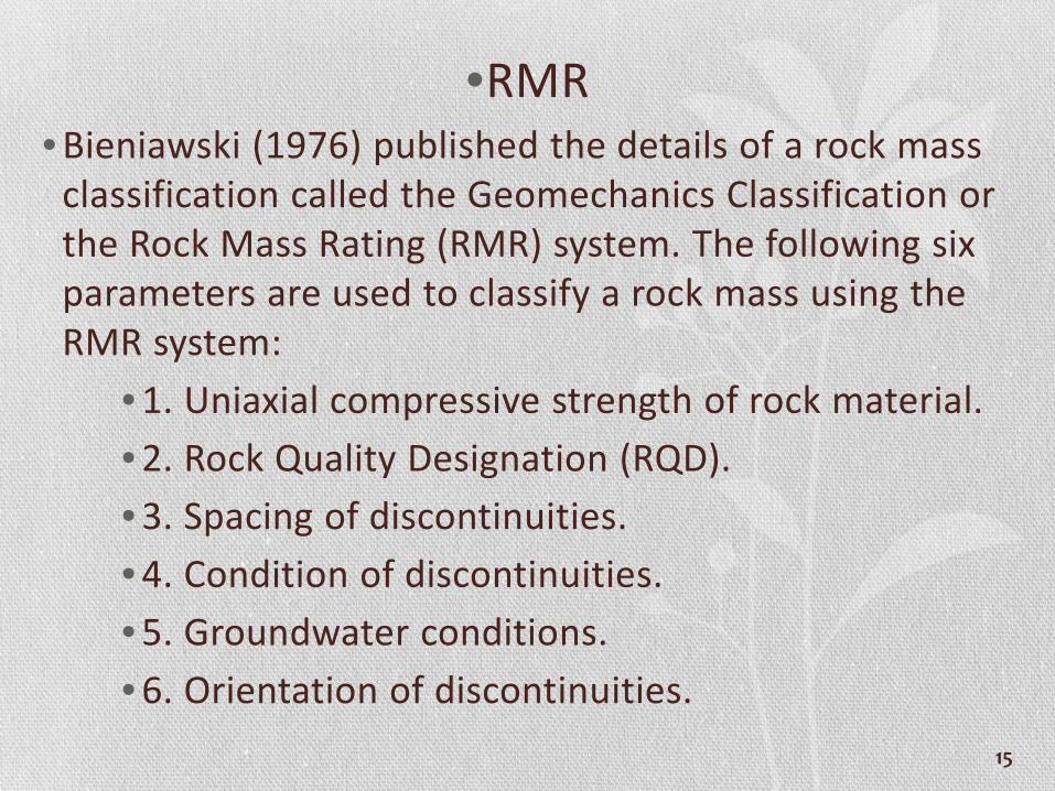
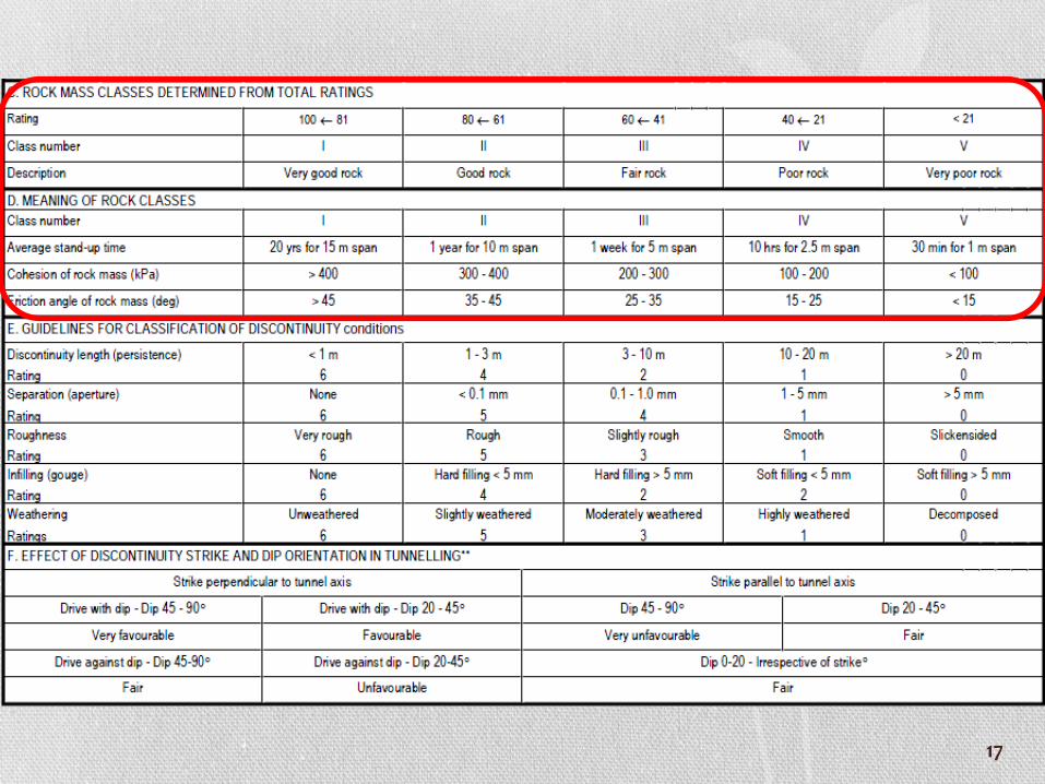
•RMR• Bieniawski (1976) published the details of a rock mass
classification called the Geomechanics Classification or the Rock Mass Rating (RMR) system. The following six parameters are used to classify a rock mass using the RMR system:
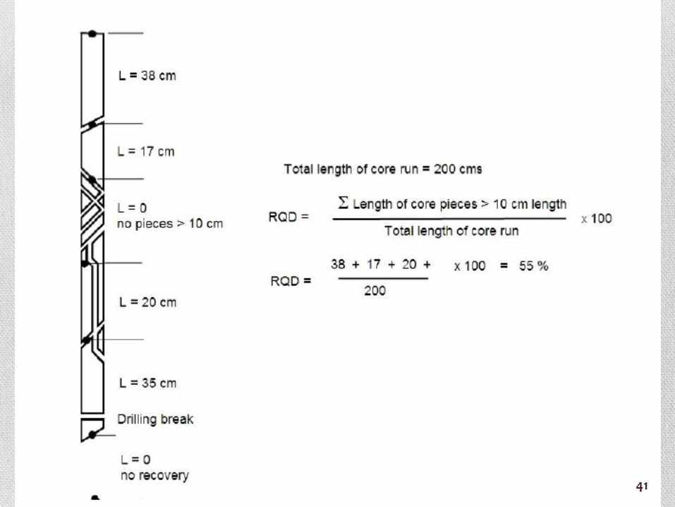
• 1. Uniaxial compressive strength of rock material.• 2. Rock Quality Designation (RQD).• 3. Spacing of discontinuities.• 4. Condition of discontinuities.• 5. Groundwater conditions.• 6. Orientation of discontinuities.
15

16
17
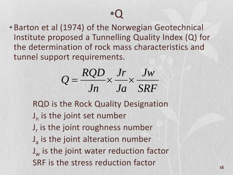
•Q• Barton et al (1974) of the Norwegian Geotechnical
Institute proposed a Tunnelling Quality Index (Q) for the determination of rock mass characteristics and tunnel support requirements.
RQD is the Rock Quality DesignationJn is the joint set numberJr is the joint roughness numberJa is the joint alteration numberJw is the joint water reduction factorSRF is the stress reduction factor
SRFJw
JaJr
JnRQDQ ××=
18
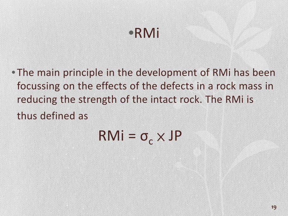
•RMi
• The main principle in the development of RMi has been focussing on the effects of the defects in a rock mass in reducing the strength of the intact rock. The RMi is thus defined as
RMi = σc × JP
19

20
21
Numerical modelling study
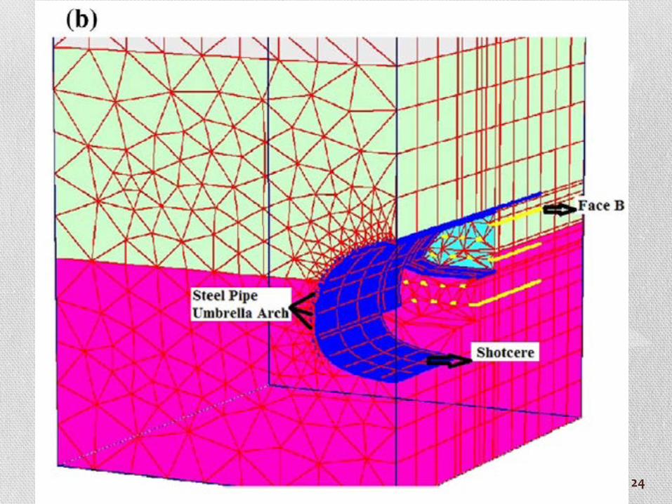
• Excavation-support stages in the field are integrated exactly in modeling studies. The methodology used at a numerical modelling is the same as the methodology used at this type of works. In a numerical modellingstudy, firstly excavation stage is completed and then support is carried out. Those processes are defined into models in various stages, depending on the construction of tunnel.
22

23
24

Mon
itorin
g of
fie
ld m
easu
rem
ent
25
Results and discussions• 12 hydroelectric plant tunnels and 3 metro tunnels
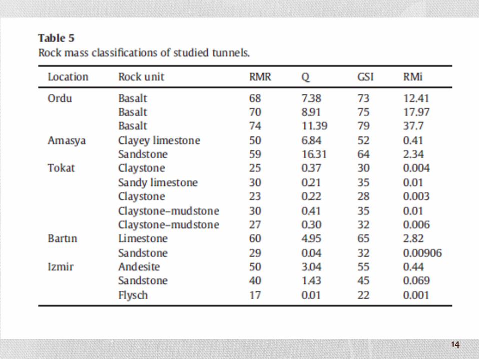
were examined in the scope of this research. The descriptions of the rock mass in tunnels were made with the most-used rock mass classifications (RMR, Q, GSI and RMI).
• Deformation module of the rock masses was estimated by the help of different empirical equations based on those classifications.
• The main purpose of this study is to compare the numerical modelling results and convergence measurements at tunnels having different rock mass properties.
26
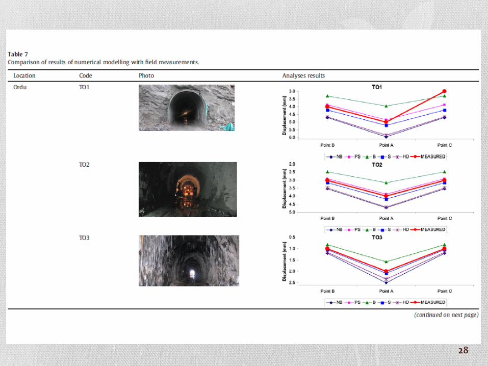
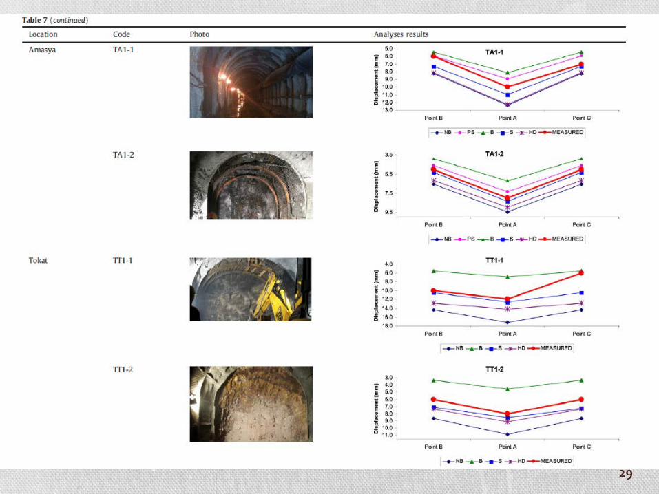
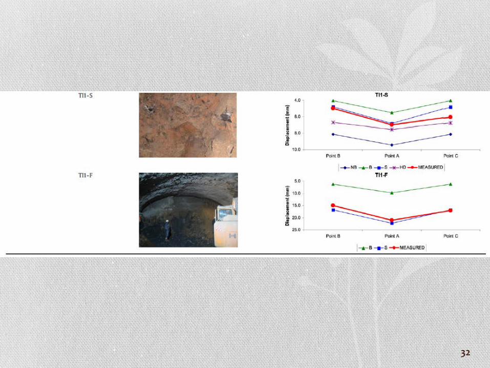
• Keeping all the initial parameters and boundary conditions constant, except rock deformation modulus, results were examined. Vertical deformation values obtained from both measurement points at tunnels and from numerical models were evaluated for examination of results (Table 7).
27
28
29

30

31
32
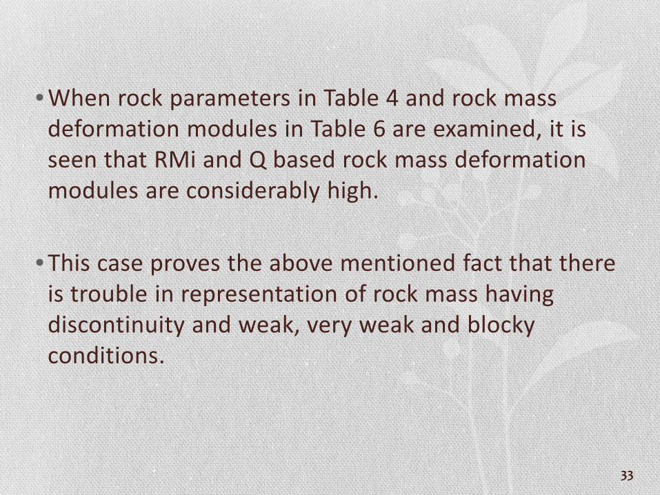
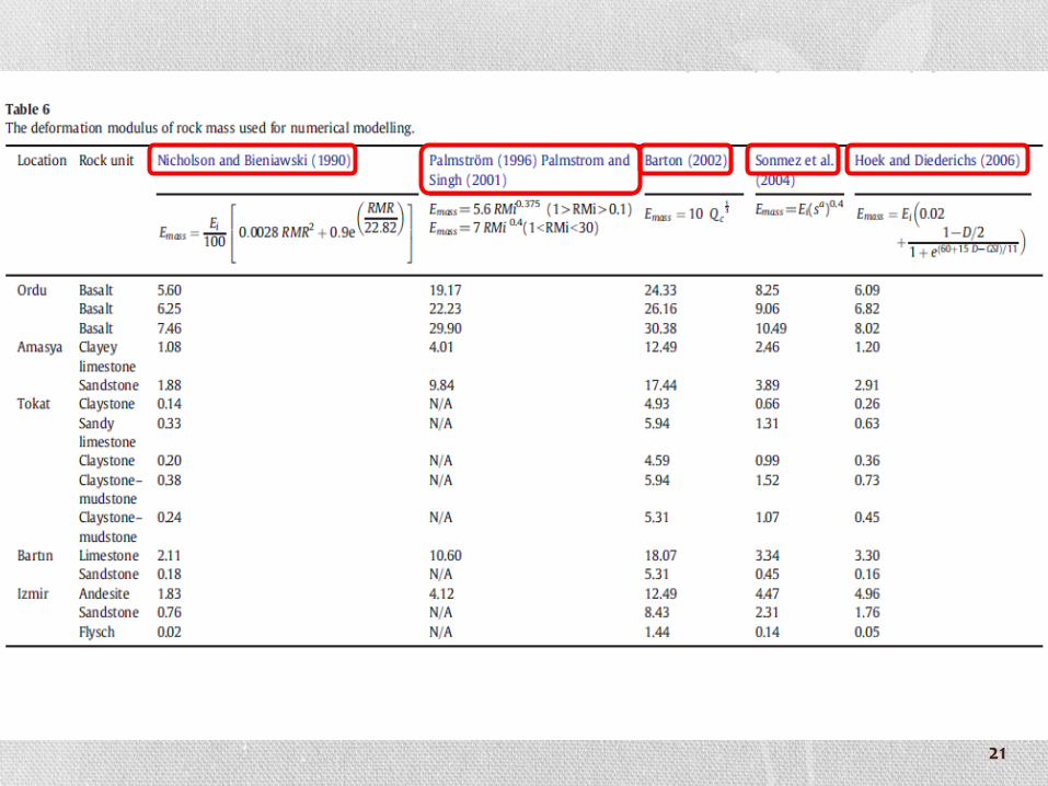
• When rock parameters in Table 4 and rock mass deformation modules in Table 6 are examined, it is seen that RMi and Q based rock mass deformation modules are considerably high.
• This case proves the above mentioned fact that there is trouble in representation of rock mass having discontinuity and weak, very weak and blocky conditions.
33

• Investigating the rock mass deformation modulus suggested by Barton (2002) in Table 6, it is seen that their values are higher than others. Palmstrom and Broch (2006) explained this situation with the criticism to Q system; “requirement of wide blocks to characterize joints correctly”.
• Higher rock mass deformation values can be comprehended from vertical convergence measurements obtained both from in situ measurements and numerical modelling (Table 7).
34
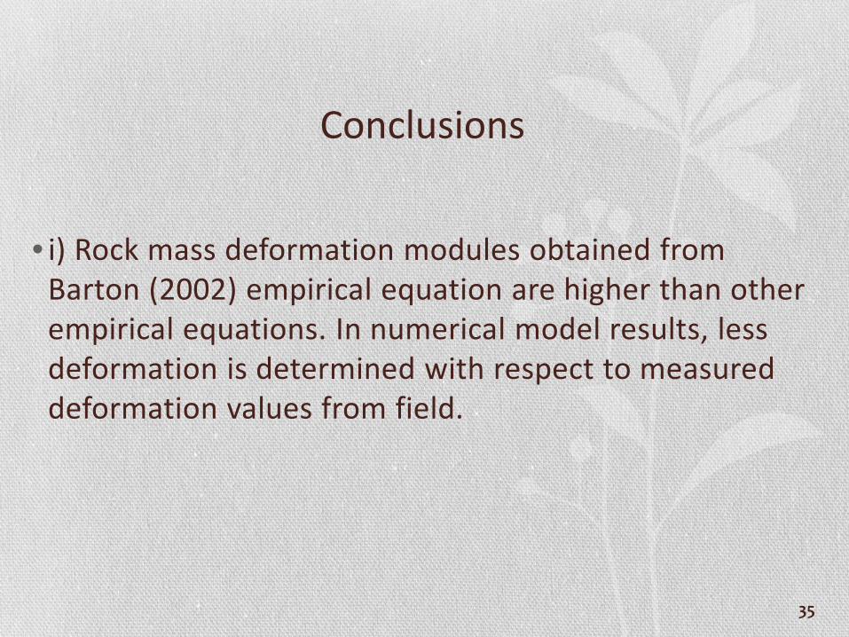
Conclusions
• i) Rock mass deformation modules obtained from Barton (2002) empirical equation are higher than other empirical equations. In numerical model results, less deformation is determined with respect to measured deformation values from field.
35

• ii) Rock mass deformation modules calculated through suggested empirical equation by Palmstrom and Singh (2001) gives more realistic results in tunnels which have hard (almost brittle level) and big block sized rock mass. For medium and weak rock masses (especially very blocky rock mass), however, results diverge from measured deformation values. Thus, it is considered that using RMi based rock mass deformation modules are more convenient for hard and big block sized masses.
36
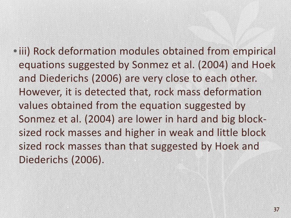
• iii) Rock deformation modules obtained from empirical equations suggested by Sonmez et al. (2004) and Hoekand Diederichs (2006) are very close to each other. However, it is detected that, rock mass deformation values obtained from the equation suggested by Sonmez et al. (2004) are lower in hard and big block-sized rock masses and higher in weak and little block sized rock masses than that suggested by Hoek and Diederichs (2006).
37

• iv) Performance of the equation suggested by Sonmezet al. (2004) for determining the rock mass deformation modulus in numerical modelling is more realistic.
38

THANK YOU
~END~
39

40
41


![Projekt[NoeSLIDE] · Anna Iglseder (MSc 2018) Detection of surface changes using terrestrial laser scanning: A field study on rock instabilities in the Ybbs Valley, Lower Austria](https://img.pdfslide.org/doc/110x75/5e200513db57195a42307530/projektnoeslide-anna-iglseder-msc-2018-detection-of-surface-changes-using-terrestrial.jpg)