Embed Size (px)
Citation preview
A Quartz Cherenkov Detector forPolarimetry at the ILC.Jenny List, Annika Vauth Mainz, 13.02.2014
Spin-Optimierung polarisierter Leptonstrahlen an Beschleunigern
(BMBF-Verbundforschungsprojekt mit UHH, Mainz, Bonn)
Teil-Projekt "Spin-Umsetzung":
Erreichbare Genauigkeit von Compton-Polarimetern
ILC Polarimetry Design Application Conclusion
Polarimetry at the ILC
Quarz detector design
Detector application
Summary and Outlook
Quartz Detector for ILC Polarimetry | A. Vauth | Mainz, 13.02.14 | 0/19
ILC Polarimetry Design Application Conclusion
Polarimetry at the ILC
Quarz detector design
Detector application
Summary and Outlook
Quartz Detector for ILC Polarimetry | A. Vauth | Mainz, 13.02.14 | 1/19
ILC Polarimetry Design Application Conclusion
Polarimetry at the ILC.
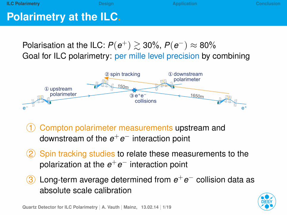
Polarisation at the ILC: P(e+) & 30%, P(e−) ≈ 80%Goal for ILC polarimetry: per mille level precision by combining
1650m
150m
e⁻ e⁺
e⁺e⁻collisions
③upstreampolarimeter
①
downstreampolarimeter
①spin tracking②
1 Compton polarimeter measurements upstream anddownstream of the e+e− interaction point
2 Spin tracking studies to relate these measurements to thepolarization at the e+e− interaction point
3 Long-term average determined from e+e− collision data asabsolute scale calibration
Quartz Detector for ILC Polarimetry | A. Vauth | Mainz, 13.02.14 | 1/19
ILC Polarimetry Design Application Conclusion
Compton polarimeters.
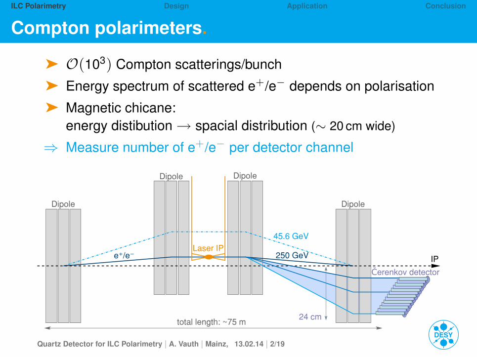
ä O(103) Compton scatterings/bunch
ä Energy spectrum of scattered e+/e− depends on polarisation
ä Magnetic chicane:energy distibution→ spacial distribution (∼ 20 cm wide)
⇒ Measure number of e+/e− per detector channel
24 cm
45.6 GeV
Laser IP
Dipole Dipole
DipoleDipole
total length: ~75 m
IPe⁺/e⁻
Čerenkov detector
250 GeV
Quartz Detector for ILC Polarimetry | A. Vauth | Mainz, 13.02.14 | 2/19
ILC Polarimetry Design Application Conclusion
Measurement principle.
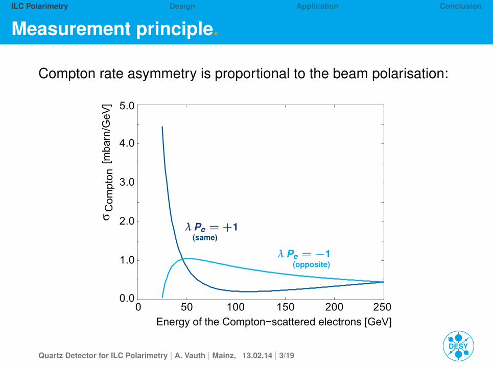
Compton rate asymmetry is proportional to the beam polarisation:
0 50 100 150 200 2500.0
1.0
2.0
3.0
4.0
5.0σ
Energy of the Compton−scattered electrons [GeV]
[mba
rn/G
eV]
Com
pton
λ Pe = +1(same)
λ Pe = −1(opposite)
Quartz Detector for ILC Polarimetry | A. Vauth | Mainz, 13.02.14 | 3/19
ILC Polarimetry Design Application Conclusion
Measurement principle.
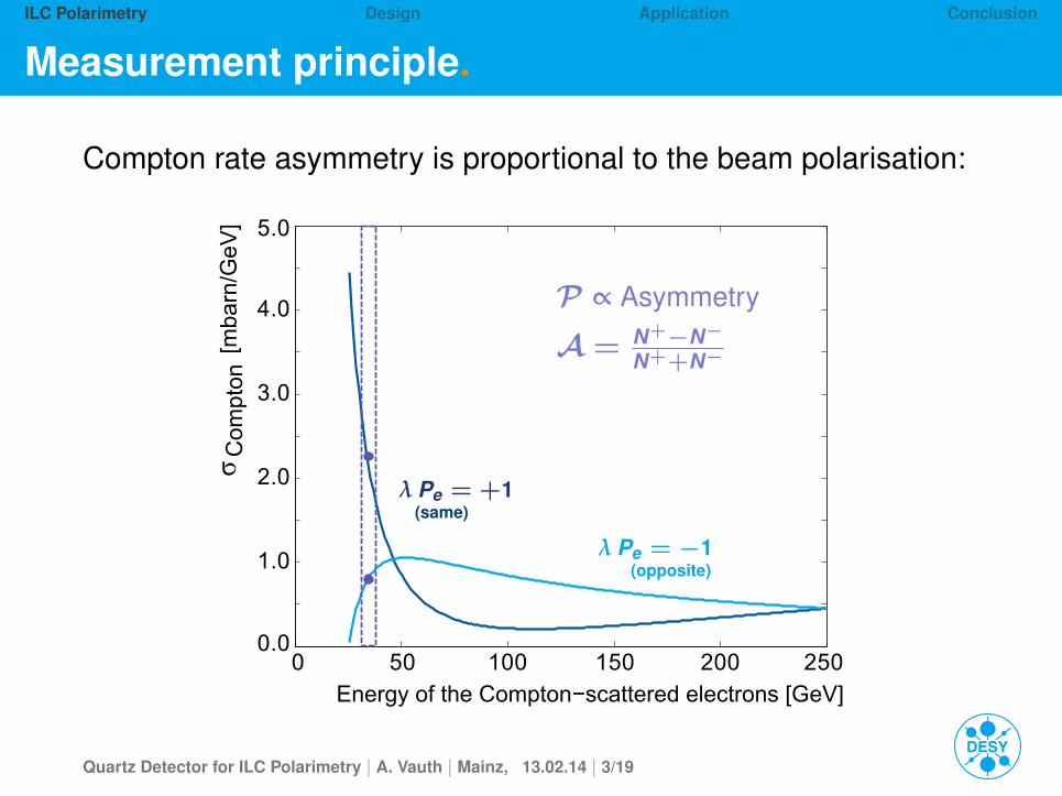
Compton rate asymmetry is proportional to the beam polarisation:
0 50 100 150 200 2500.0
1.0
2.0
3.0
4.0
5.0σ
Energy of the Compton−scattered electrons [GeV]
[mba
rn/G
eV]
Com
pton
λ Pe = +1(same)
λ Pe = −1(opposite)
P ∝ Asymmetry
A = N+−N−N++N−
Quartz Detector for ILC Polarimetry | A. Vauth | Mainz, 13.02.14 | 3/19
ILC Polarimetry Design Application Conclusion
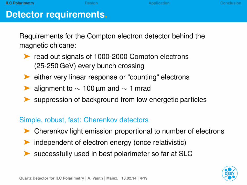
Detector requirements.
Requirements for the Compton electron detector behind themagnetic chicane:
ä read out signals of 1000-2000 Compton electrons(25-250 GeV) every bunch crossing
ä either very linear response or “counting“ electrons
ä alignment to ∼ 100 µm and ∼ 1 mrad
ä suppression of background from low energetic particles
Simple, robust, fast: Cherenkov detectors
ä Cherenkov light emission proportional to number of electrons
ä independent of electron energy (once relativistic)
ä successfully used in best polarimeter so far at SLC
Quartz Detector for ILC Polarimetry | A. Vauth | Mainz, 13.02.14 | 4/19
ILC Polarimetry Design Application Conclusion
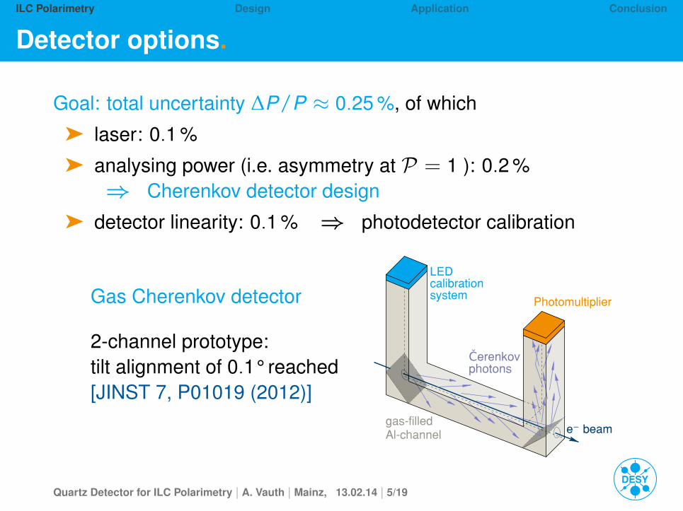
Detector options.
Goal: total uncertainty ∆P/P ≈ 0.25 %, of which
ä laser: 0.1 %
ä analysing power (i.e. asymmetry at P = 1 ): 0.2 %⇒ Cherenkov detector design
ä detector linearity: 0.1 % ⇒ photodetector calibration
Gas Cherenkov detector
2-channel prototype:tilt alignment of 0.1° reached[JINST 7, P01019 (2012)]
e⁻ beam
Čerenkovphotons
Photomultiplier
LED calibration system
gas-filled Al-channel
Quartz Detector for ILC Polarimetry | A. Vauth | Mainz, 13.02.14 | 5/19
ILC Polarimetry Design Application Conclusion
Detector options.
Goal: total uncertainty ∆P/P ≈ 0.25 %, of which
ä laser: 0.1 %
ä analysing power (i.e. asymmetry at P = 1 ): 0.2 %
⇒ Cherenkov detector design
ä detector linearity: 0.1 % ⇒ photodetector calibration
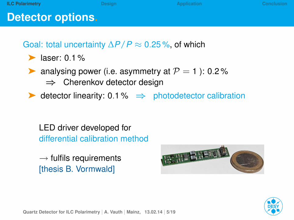
LED driver developed for
differential calibration method
→ fulfils requirements
[thesis B. Vormwald]
Quartz Detector for ILC Polarimetry | A. Vauth | Mainz, 13.02.14 | 5/19
ILC Polarimetry Design Application Conclusion
Detector options.
Goal: total uncertainty ∆P/P ≈ 0.25 %, of which
ä laser: 0.1 %
ä analysing power (i.e. asymmetry at P = 1 ): 0.2 %⇒ Cherenkov detector design
ä detector linearity: 0.1 % ⇒ photodetector calibration
In the scope of the BMBF spin optimisation project:
Alternate detector concept studied:Quartz as Cherenkov material.
Quartz Detector for ILC Polarimetry | A. Vauth | Mainz, 13.02.14 | 5/19
ILC Polarimetry Design Application Conclusion
Polarimetry at the ILC
Quarz detector design
Detector application
Summary and Outlook
Quartz Detector for ILC Polarimetry | A. Vauth | Mainz, 13.02.14 | 6/19
ILC Polarimetry Design Application Conclusion
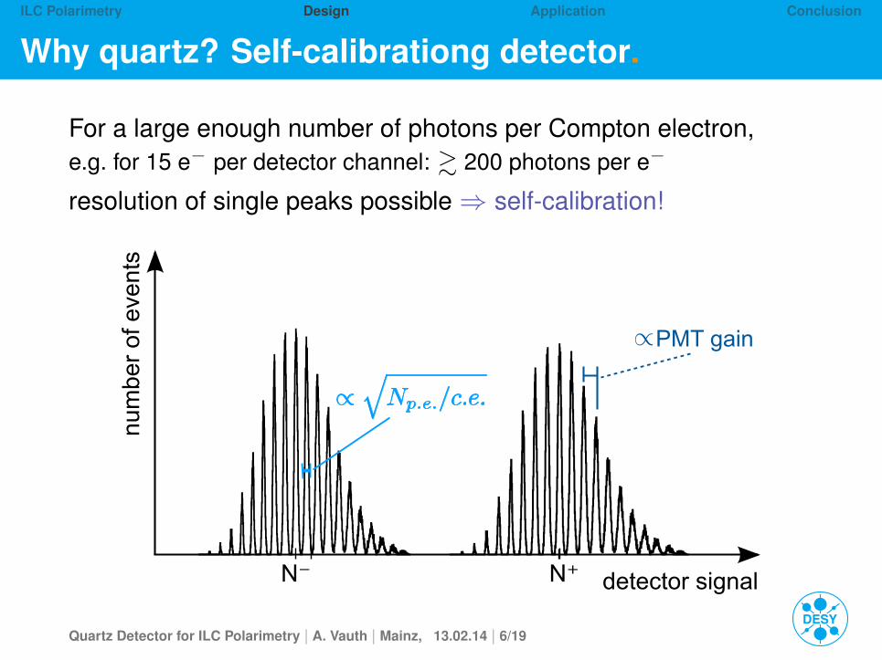
Why quartz? Self-calibrationg detector.
For a large enough number of photons per Compton electron,e.g. for 15 e− per detector channel: & 200 photons per e−
resolution of single peaks possible⇒ self-calibration!
PMT gain
detector signal
num
ber
of e
vent
s
N⁻ N⁺
Quartz Detector for ILC Polarimetry | A. Vauth | Mainz, 13.02.14 | 6/19
ILC Polarimetry Design Application Conclusion
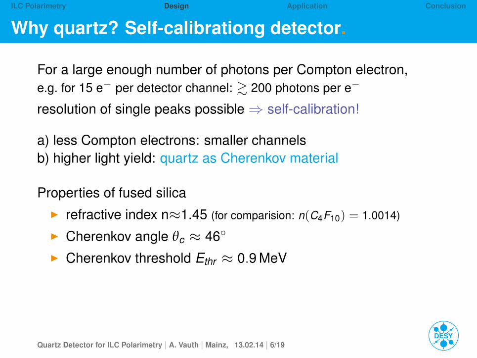
Why quartz? Self-calibrationg detector.
For a large enough number of photons per Compton electron,e.g. for 15 e− per detector channel: & 200 photons per e−
resolution of single peaks possible⇒ self-calibration!
a) less Compton electrons: smaller channelsb) higher light yield: quartz as Cherenkov material
Properties of fused silicaI refractive index n≈1.45 (for comparision: n(C4F10) = 1.0014)
I Cherenkov angle θc ≈ 46◦
I Cherenkov threshold Ethr ≈ 0.9 MeV
Quartz Detector for ILC Polarimetry | A. Vauth | Mainz, 13.02.14 | 6/19
ILC Polarimetry Design Application Conclusion
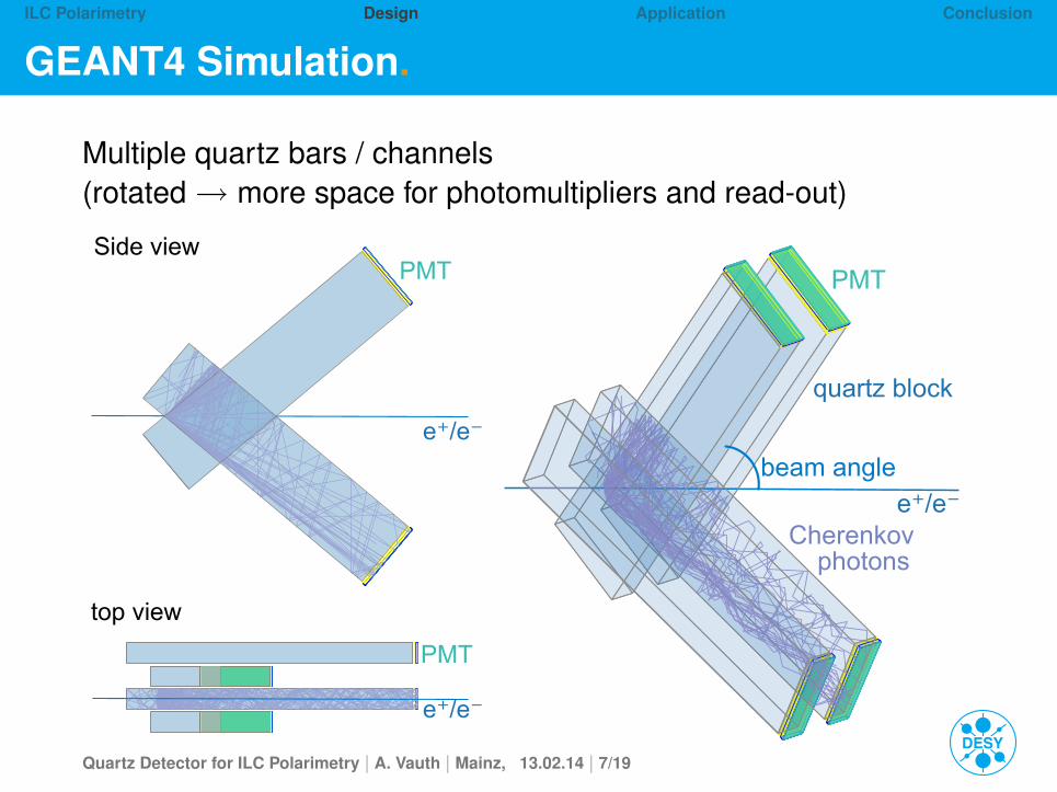
GEANT4 Simulation.
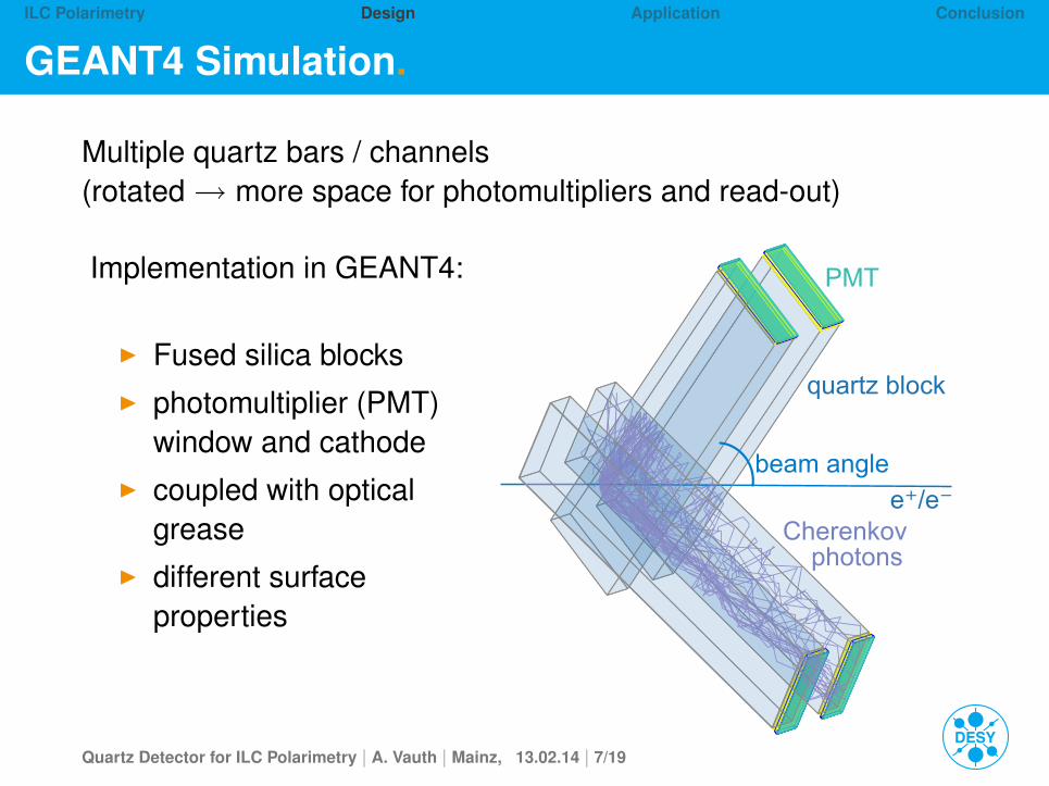
Multiple quartz bars / channels(rotated→ more space for photomultipliers and read-out)
e⁺/e⁻
e⁺/e⁻
PMTSide view
top view
PMT
Implementation in GEANT4:
I Fused silica blocksI photomultiplier (PMT)
window and cathodeI coupled with optical
greaseI different surface
properties
Cherenkov photons
quartz block
PMT
e⁺/e⁻beam angle
Quartz Detector for ILC Polarimetry | A. Vauth | Mainz, 13.02.14 | 7/19
ILC Polarimetry Design Application Conclusion
GEANT4 Simulation.
Multiple quartz bars / channels(rotated→ more space for photomultipliers and read-out)
e⁺/e⁻
e⁺/e⁻
PMTSide view
top view
PMT
Implementation in GEANT4:
I Fused silica blocksI photomultiplier (PMT)
window and cathodeI coupled with optical
greaseI different surface
properties
Cherenkov photons
quartz block
PMT
e⁺/e⁻beam angle
Quartz Detector for ILC Polarimetry | A. Vauth | Mainz, 13.02.14 | 7/19
ILC Polarimetry Design Application Conclusion
Detector geometry.
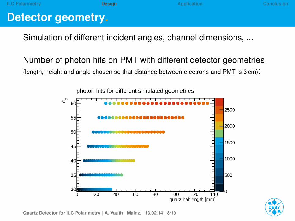
Simulation of different incident angles, channel dimensions, ...
Number of photon hits on PMT with different detector geometries(length, height and angle chosen so that distance between electrons and PMT is 3 cm):
quarz halflength [mm]0 20 40 60 80 100 120 140
yα
30
35
40
45
50
55
60
0
500
1000
1500
2000
2500
photon hits for different simulated geometries
Quartz Detector for ILC Polarimetry | A. Vauth | Mainz, 13.02.14 | 8/19
ILC Polarimetry Design Application Conclusion
Quartz prototype.
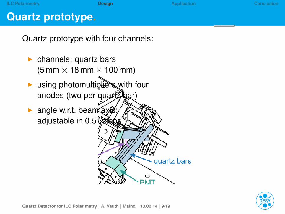
Quartz prototype with four channels:
I channels: quartz bars(5 mm× 18 mm× 100 mm)
I using photomultipliers with fouranodes (two per quartz bar)
I angle w.r.t. beam axis:adjustable in 0.5° steps
⇒
Quartz Detector for ILC Polarimetry | A. Vauth | Mainz, 13.02.14 | 9/19
ILC Polarimetry Design Application Conclusion
Quartz prototype.
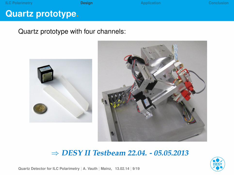
Quartz prototype with four channels:
⇒ DESY II Testbeam 22.04. - 05.05.2013
Quartz Detector for ILC Polarimetry | A. Vauth | Mainz, 13.02.14 | 9/19
ILC Polarimetry Design Application Conclusion
Polarimetry at the ILC
Quarz detector design
Detector application
Summary and Outlook
Quartz Detector for ILC Polarimetry | A. Vauth | Mainz, 13.02.14 | 10/19
ILC Polarimetry Design Application Conclusion
DESY Testbeam 2013.
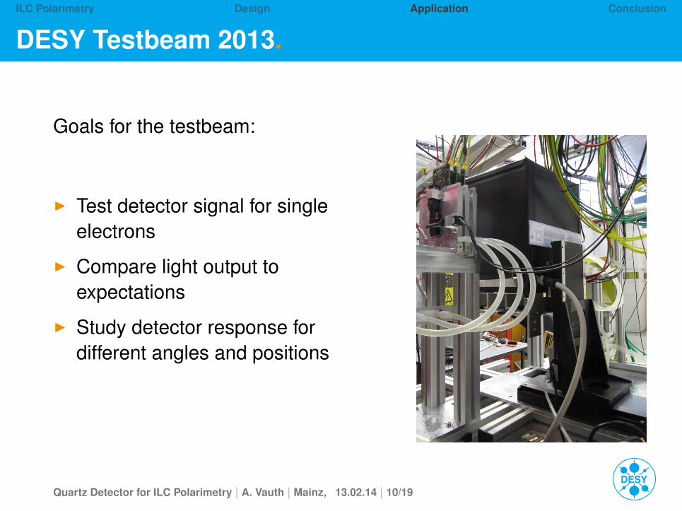
Goals for the testbeam:
◮ Test detector signal for single
electrons
◮ Compare light output to
expectations
◮ Study detector response for
different angles and positions
Quartz Detector for ILC Polarimetry | A. Vauth | Mainz, 13.02.14 | 10/19
ILC Polarimetry Design Application Conclusion
DESY Testbeam: Setup.
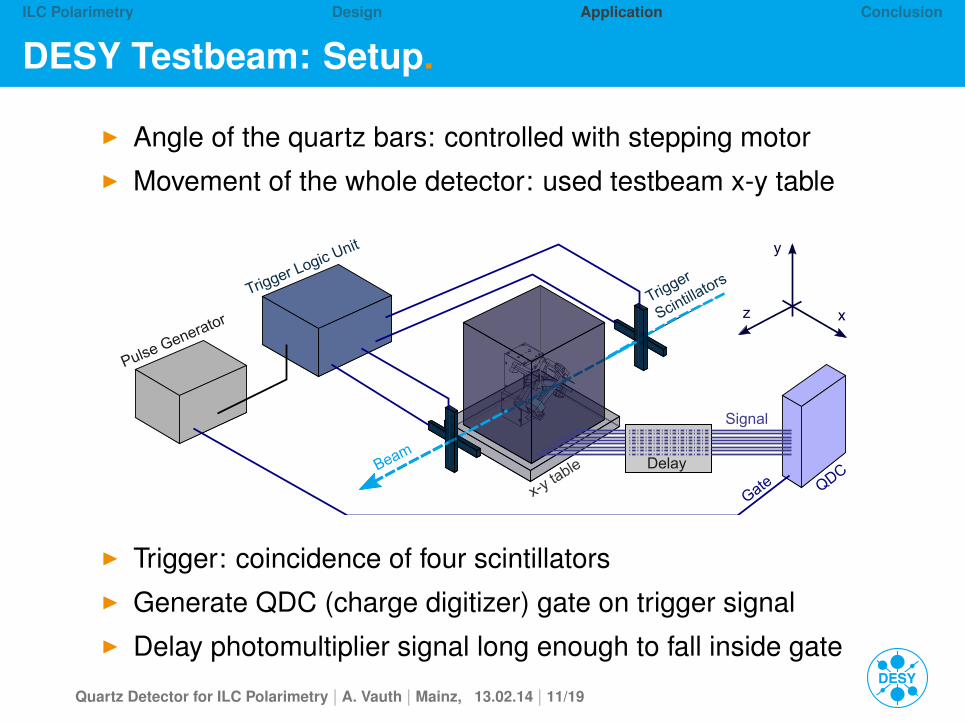
I Angle of the quartz bars: controlled with stepping motorI Movement of the whole detector: used testbeam x-y table
Beam
Trigger
ScintillatorsTrigger Logic Unit
Pulse Generator z x
y
QDCDelay
Signal
Gatex-y table
I Trigger: coincidence of four scintillatorsI Generate QDC (charge digitizer) gate on trigger signalI Delay photomultiplier signal long enough to fall inside gate
Quartz Detector for ILC Polarimetry | A. Vauth | Mainz, 13.02.14 | 11/19
ILC Polarimetry Design Application Conclusion
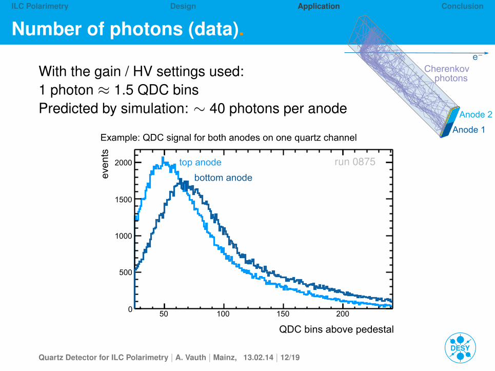
Number of photons (data).
Cherenkov photons
e⁻
Anode 2
Anode 1
run 0875
With the gain / HV settings used:1 photon ≈ 1.5 QDC binsPredicted by simulation: ∼ 40 photons per anode
QDC bins above pedestal
50 100 150 200
even
ts
0
500
1000
1500
2000
Example: QDC signal for both anodes on one quartz channel
top anode
bottom anode
Quartz Detector for ILC Polarimetry | A. Vauth | Mainz, 13.02.14 | 12/19
ILC Polarimetry Design Application Conclusion
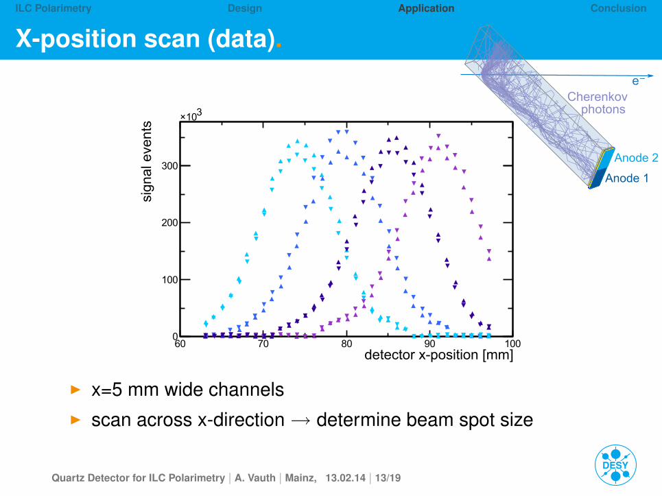
X-position scan (data).
Cherenkov photons
e⁻
Anode 2
Anode 1
detector x-position [mm] 60 70 80 90 100
sign
al e
vent
s
0
100
200
300
310×
I x=5 mm wide channelsI scan across x-direction→ determine beam spot size
Quartz Detector for ILC Polarimetry | A. Vauth | Mainz, 13.02.14 | 13/19
ILC Polarimetry Design Application Conclusion
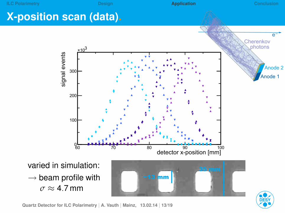
X-position scan (data).
Cherenkov photons
e⁻
Anode 2
Anode 1
detector x-position [mm] 60 70 80 90 100
sign
al e
vent
s
0
100
200
300
310×
35 mm~13 mm
varied in simulation:→ beam profile with
σ ≈ 4.7 mm
Quartz Detector for ILC Polarimetry | A. Vauth | Mainz, 13.02.14 | 13/19
ILC Polarimetry Design Application Conclusion
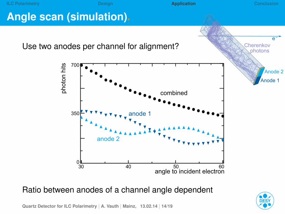
Angle scan (simulation).
Cherenkov photons
e⁻
Anode 2
Anode 1
Use two anodes per channel for alignment?
0
350
700
combined
anode 2
anode 1
angle to incident electron
phot
on h
its
30 40 50 60
Ratio between anodes of a channel angle dependent
Quartz Detector for ILC Polarimetry | A. Vauth | Mainz, 13.02.14 | 14/19
ILC Polarimetry Design Application Conclusion
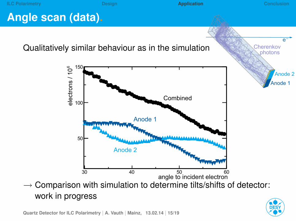
Angle scan (data).
Cherenkov photons
e⁻
Anode 2
Anode 1
Qualitatively similar behaviour as in the simulation
angle to incident electron30 40 50 60
6el
ectr
ons
/ 10
50
100
150
Anode 2
Anode 1
Combined
→ Comparison with simulation to determine tilts/shifts of detector:work in progress
Quartz Detector for ILC Polarimetry | A. Vauth | Mainz, 13.02.14 | 15/19
ILC Polarimetry Design Application Conclusion
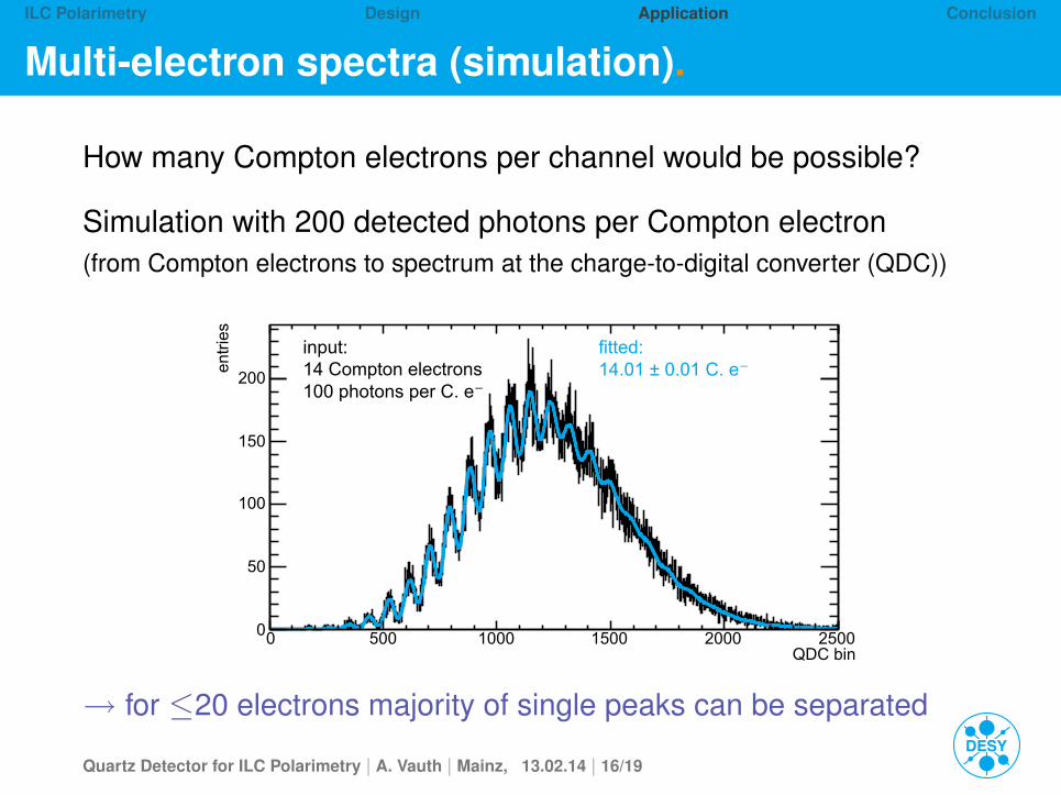
Multi-electron spectra (simulation).
How many Compton electrons per channel would be possible?
Simulation with 200 detected photons per Compton electron(from Compton electrons to spectrum at the charge-to-digital converter (QDC))
QDC bin0 500 1000 1500 2000 2500
entr
ies
0
50
100
150
200
input: 14 Compton electrons100 photons per C. e⁻
fitted: 14.01 ± 0.01 C. e⁻
→ for ≤20 electrons majority of single peaks can be separated
Quartz Detector for ILC Polarimetry | A. Vauth | Mainz, 13.02.14 | 16/19
ILC Polarimetry Design Application Conclusion
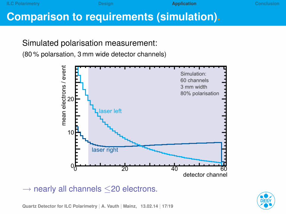
Comparison to requirements (simulation).
Simulated polarisation measurement:(80 % polarsation, 3 mm wide detector channels)
detector channel0 20 40 60
mea
n el
ectr
ons
/ eve
nt
0
10
20
Simulation:60 channels3 mm width80% polarisation
laser left
laser right
→ nearly all channels ≤20 electrons.
Quartz Detector for ILC Polarimetry | A. Vauth | Mainz, 13.02.14 | 17/19
ILC Polarimetry Design Application Conclusion
Polarimetry at the ILC
Quarz detector design
Detector application
Summary and Outlook
Quartz Detector for ILC Polarimetry | A. Vauth | Mainz, 13.02.14 | 18/19
ILC Polarimetry Design Application Conclusion
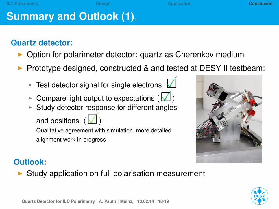
Summary and Outlook (1).
Quartz detector:
◮ Option for polarimeter detector: quartz as Cherenkov medium
◮ Prototype designed, constructed & and tested at DESY II testbeam:
◮ Test detector signal for single electrons 2�◮ Compare light output to expectations �(2)◮ Study detector response for different angles
and positions �(2)Qualitative agreement with simulation, more detailed
alignment work in progress
Outlook:
◮ Study application on full polarisation measurement
Quartz Detector for ILC Polarimetry | A. Vauth | Mainz, 13.02.14 | 18/19
ILC Polarimetry Design Application Conclusion
Summary and Outlook (2).
Compton polarimetry at ILC:
Precision goal for ILC polarimetry: ∆P/P ≈ 0.25%
Needs combination of:I scale calibration from e+e− collision dataI spin tracking and understanding of collision effectsI upstream (UP) and downstream (DP) polarimeters
I UP: time resolutionI DP: collision effectsI combined: cross-check, lumi-weighted polarisation @ IP
Outlook:I site specific studiesI detectors: prototypes→ full-scale, DAQ, ...
Quartz Detector for ILC Polarimetry | A. Vauth | Mainz, 13.02.14 | 19/19


![2. Das Silizium-Sauerstoff-System - uni-halle.de · 2. DasSilizium-Sauerstoff-System Sauerstoff [gew.%] 1723 °C CRISTOBALITE (Si) Si O L TRIDYMITE α - QUARTZ β - QUARTZ 1414 °C](https://img.pdfslide.org/doc/110x75/5f25363fda691d05ae55c121/2-das-silizium-sauerstoff-system-uni-hallede-2-dassilizium-sauerstoff-system.jpg)