Embed Size (px)
Citation preview

Page 1 of 18
Fränkische Rohrwerke Gebr. Kirchner GmbH & Co KG Hellinger Strasse 1 97486 Kӧnigsberg Bavaria Germany Tel: 0049 9525 880 Fax: 0049 9525 882412 Agrément Certificate e-mail: [email protected] 18/5516 website: www.fraenkische.com Product Sheet 1
FRÄNKISCHE STORMWATER MANAGEMENT SYSTEMS RIGOFILL ST STORMWATER MANAGEMENT SYSTEM
This Agrément Certificate Product Sheet(1) relates to the Rigofill ST Stormwater Management System, comprising polypropylene modules used to construct sub-surface stormwater storage systems or soakaways to manage stormwater run-off from impermeable surfaces.
(1) Hereinafter referred to as ‘Certificate’.
CERTIFICATION INCLUDES:
• factors relating to compliance with Building Regulations where applicable
• factors relating to additional non-regulatory information where applicable
• independently verified technical specification • assessment criteria and technical investigations • design considerations • installation guidance • regular surveillance of production • formal three-yearly review.
KEY FACTORS ASSESSED
Hydraulic design — data is provided in this Certificate to assist in the design of a below-ground stormwater management system incorporating the system (see section 6).
Structural design — the system has adequate strength and stiffness to resist short- and long-term loading when designed in accordance with this Certificate (see section 7).
Maintenance — data is provided to assist in planning the maintenance of a completed Rigofil ST Stormwater Management System installation (see section 11).
Durability — the system will have a service life of up to 50 years when installed in accordance with this Certificate (see section 12).
The BBA has awarded this Certificate to the company named above for the system described herein. This system has been assessed by the BBA as being fit for its intended use provided it is installed, used and maintained as set out in this Certificate.
On behalf of the British Board of Agrément
Date of First issue: 9 April 2018
Paul Valentine Technical Excellance Director
Claire Curtis-Thomas Chief Executive
The BBA is a UKAS accredited certification body – Number 113. The schedule of the current scope of accreditation for product certification is available in pdf format via the UKAS link on the BBA website at www.bbacerts.co.uk Readers are advised to check the validity and latest issue number of this Agrément Certificate by either referring to the BBA website or contacting the BBA direct.
British Board of Agrément Bucknalls Lane Watford Herts WD25 9BA
©2018
tel: 01923 665300
[email protected] www.bbacerts.co.uk
Page 2 of 18
Regulations
In the opinion of the BBA, the Rigofill ST Stormwater Management System, if installed, used and maintained in accordance with this Certificate, can satisfy or contribute to satisfying the relevant requirements of the following Building Regulations (the presence of a UK map indicates that the subject is related to the Building Regulations in the region or regions of the UK depicted):
The Building Regulations 2010 (England and Wales) (as amended)
Requirement: H3(3) Rainwater drainage Comment: The system can be used in a construction to satisfy this Requirement. See sections 6.1 to
6.8 of this Certificate. Regulation: 7 Materials and workmanship Comment: The system components are acceptable. See section 12 and the Installation part of this
Certificate.
The Building (Scotland) Regulations 2004 (as amended)
Regulation: 8(1)(2) Durability, workmanship and fitness of materials Comment: The system can contribute to satisfying this Regulation. See sections 11 and 12 and the
Installation part of this Certificate. Regulation: 9 Building standards applicable to construction Standard: 3.6 Surface water drainage Comment: The system components can contribute to a construction satisfying this Standard, with
reference to clauses 3.6.1(1)(2) to 3.6.5(1)(2). See sections 6.1 to 6.8 of this Certificate. Standard: 7.1(a)(b) Statement of sustainability Comment: The system can contribute to meeting the relevant requirements of Regulation 9,
Standards 1 to 6 and therefore will contribute to a construction meeting a bronze level of sustainability as defined in this Standard.
Regulation: 12 Building standards applicable to conversions Comment: All comments given for the system under Regulation 9, Standards 1 to 6 also apply to this
Regulation, with reference to clause 0.12.1(1)(2) and Schedule 6(1)(2). (1) Technical Handbook (Domestic).
(2) Technical Handbook (Non-Domestic).
The Building Regulations (Northern Ireland) 2012 (as amended)
Regulation: 23(a)(i) Fitness of materials and workmanship Comment: (iii)(b)(i) The system components are acceptable. See section 12 and the Installation part of this
Certificate. Regulation: 82 Rainwater drainage Comment: The system can be used in a construction to satisfy this Regulation. See sections 6.1 to
6.8 of this Certificate.
Construction (Design and Management) Regulations 2015 Construction (Design and Management) Regulations (Northern Ireland) 2016
Page 3 of 18
Information in this Certificate may assist the client, designer (including Principal Designer) and contractor (including Principal Contractor) to address their obligations under these Regulations. See sections: 1 Description (1.3), 3 Delivery and site handling (3.1, 3.2 and 3.4), 15 Procedure (15.1) and
the Installation part of this Certificate.
Technical Specification
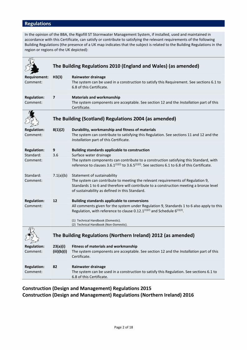
1 Description 1.1 The Rigofill ST Stormwater Management System is a geo-cellular stormwater management system comprising polypropylene modular units that connect together. 1.2 The system components are made of a mixture of polypropylene (virgin and recycled) with the addition of a stabiliser/colour. The system consists of:
• Rigofill ST Block (see Figure 1)
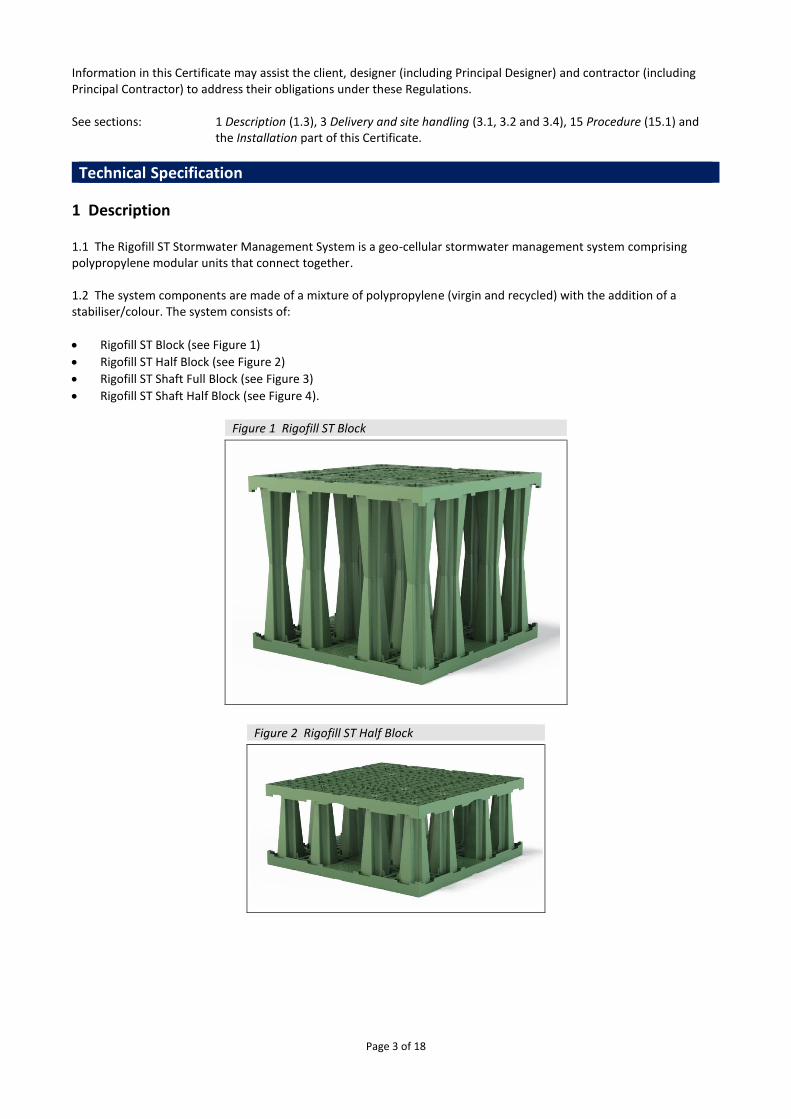
• Rigofill ST Half Block (see Figure 2)
• Rigofill ST Shaft Full Block (see Figure 3)
• Rigofill ST Shaft Half Block (see Figure 4).
Figure 1 Rigofill ST Block
Figure 2 Rigofill ST Half Block
Page 4 of 18
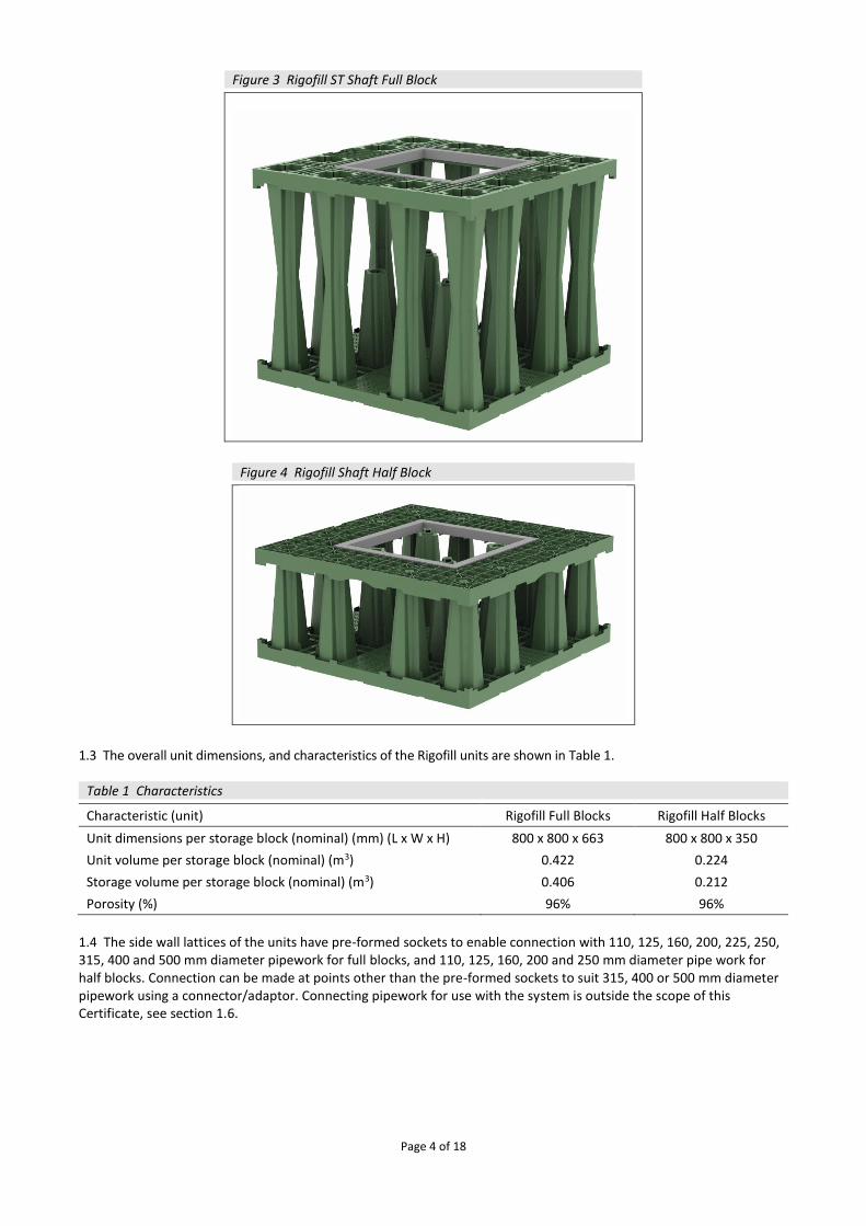
Figure 3 Rigofill ST Shaft Full Block
Figure 4 Rigofill Shaft Half Block
1.3 The overall unit dimensions, and characteristics of the Rigofill units are shown in Table 1.
Table 1 Characteristics Characteristic (unit) Rigofill Full Blocks Rigofill Half Blocks
Unit dimensions per storage block (nominal) (mm) (L x W x H) 800 x 800 x 663 800 x 800 x 350
Unit volume per storage block (nominal) (m3) 0.422 0.224
Storage volume per storage block (nominal) (m3) 0.406 0.212
Porosity (%) 96% 96%
1.4 The side wall lattices of the units have pre-formed sockets to enable connection with 110, 125, 160, 200, 225, 250, 315, 400 and 500 mm diameter pipework for full blocks, and 110, 125, 160, 200 and 250 mm diameter pipe work for half blocks. Connection can be made at points other than the pre-formed sockets to suit 315, 400 or 500 mm diameter pipework using a connector/adaptor. Connecting pipework for use with the system is outside the scope of this Certificate, see section 1.6.
Page 5 of 18
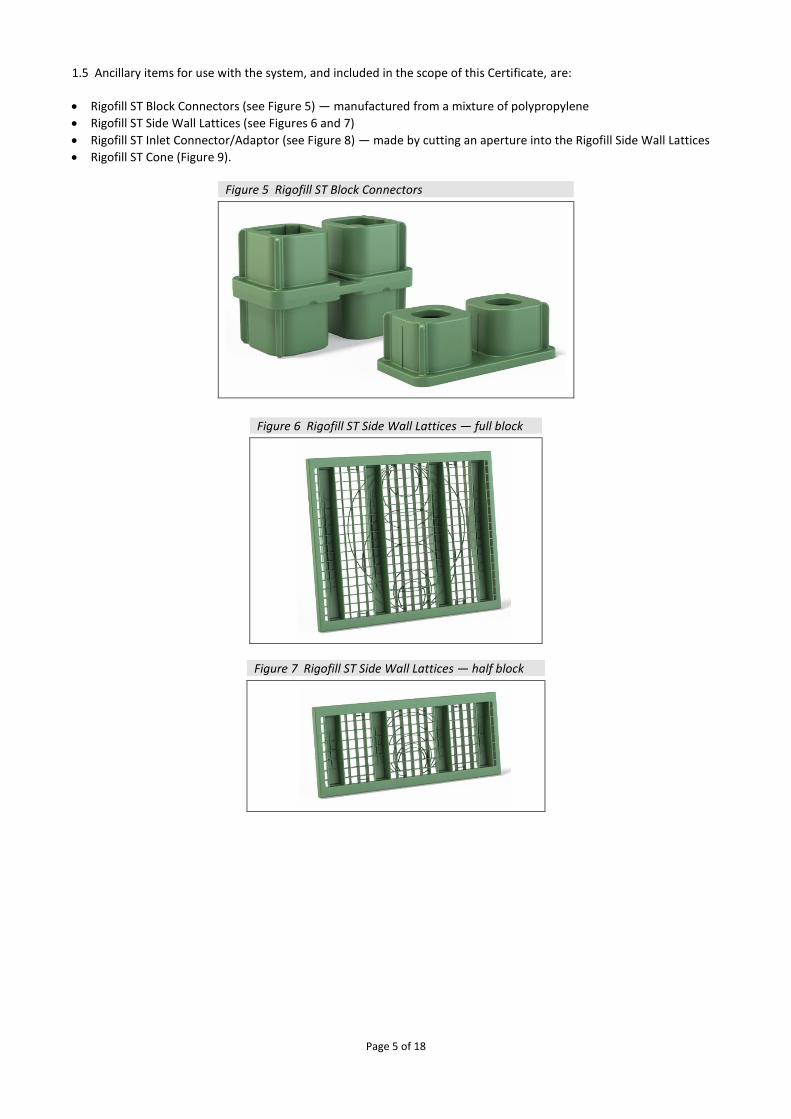
1.5 Ancillary items for use with the system, and included in the scope of this Certificate, are:
• Rigofill ST Block Connectors (see Figure 5) — manufactured from a mixture of polypropylene
• Rigofill ST Side Wall Lattices (see Figures 6 and 7)
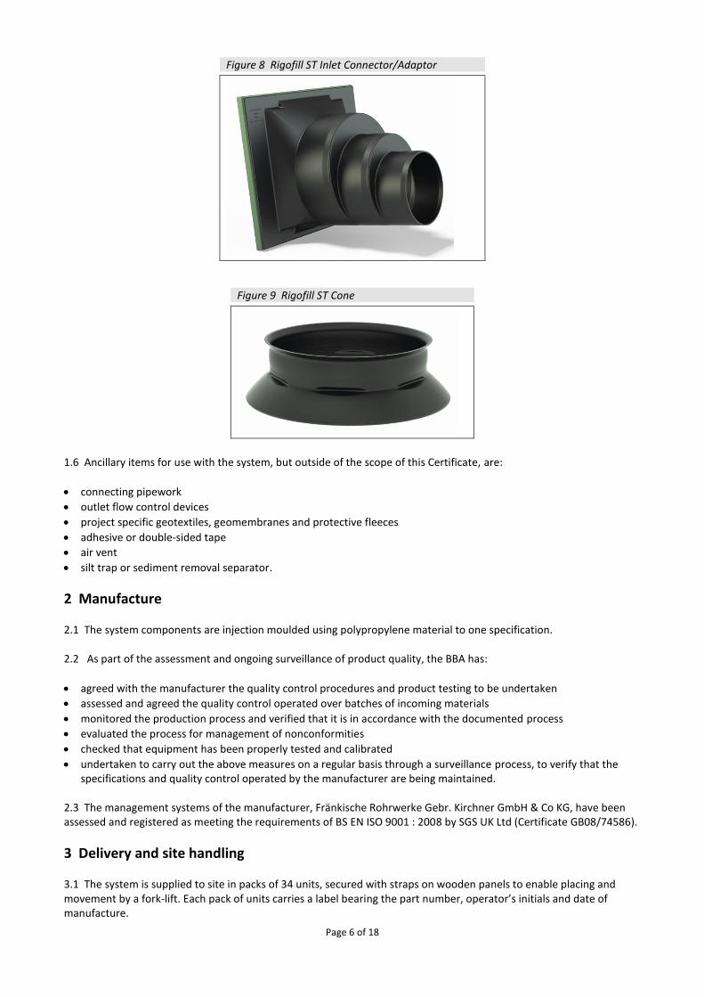
• Rigofill ST Inlet Connector/Adaptor (see Figure 8) — made by cutting an aperture into the Rigofill Side Wall Lattices
• Rigofill ST Cone (Figure 9).
Figure 5 Rigofill ST Block Connectors
Figure 6 Rigofill ST Side Wall Lattices — full block
Figure 7 Rigofill ST Side Wall Lattices — half block
Page 6 of 18
Figure 8 Rigofill ST Inlet Connector/Adaptor
Figure 9 Rigofill ST Cone
1.6 Ancillary items for use with the system, but outside of the scope of this Certificate, are:
• connecting pipework
• outlet flow control devices
• project specific geotextiles, geomembranes and protective fleeces
• adhesive or double-sided tape
• air vent
• silt trap or sediment removal separator.
2 Manufacture 2.1 The system components are injection moulded using polypropylene material to one specification. 2.2 As part of the assessment and ongoing surveillance of product quality, the BBA has:
• agreed with the manufacturer the quality control procedures and product testing to be undertaken
• assessed and agreed the quality control operated over batches of incoming materials
• monitored the production process and verified that it is in accordance with the documented process
• evaluated the process for management of nonconformities
• checked that equipment has been properly tested and calibrated
• undertaken to carry out the above measures on a regular basis through a surveillance process, to verify that the specifications and quality control operated by the manufacturer are being maintained.
2.3 The management systems of the manufacturer, Fränkische Rohrwerke Gebr. Kirchner GmbH & Co KG, have been assessed and registered as meeting the requirements of BS EN ISO 9001 : 2008 by SGS UK Ltd (Certificate GB08/74586).
3 Delivery and site handling 3.1 The system is supplied to site in packs of 34 units, secured with straps on wooden panels to enable placing and movement by a fork-lift. Each pack of units carries a label bearing the part number, operator’s initials and date of manufacture.

Page 7 of 18
3.2 Connection pieces are packed in sealed, polyethylene bags of 100 each bearing the product identification and article number, or packed in cardboard boxes bearing the same information. The packs of units should be carefully placed on level ground and should not be stacked on site. Loose individual units should not be stored more than two units high.
3.3 The units contain an inhibitor to resist the effects of ultraviolet light for up to six months. However, prolonged exposure to direct sunlight should be avoided.
3.4 The system components should not be stored near fuel bowsers, fuel tanks or other solvents, to avoid potential chemical damage.
3.5 The units are resistant to damage that could occur with normal handling. However, they should be stored in locations where impact from vehicles and other construction plant will be avoided.
3.6 Prior to installation, all components of the system should be checked for damage. Damaged or defective components must not be installed.
Assessment and Technical Investigations The following is a summary of the assessment and technical investigations carried out on the Rigofill ST Stormwater Management System.
Design Considerations
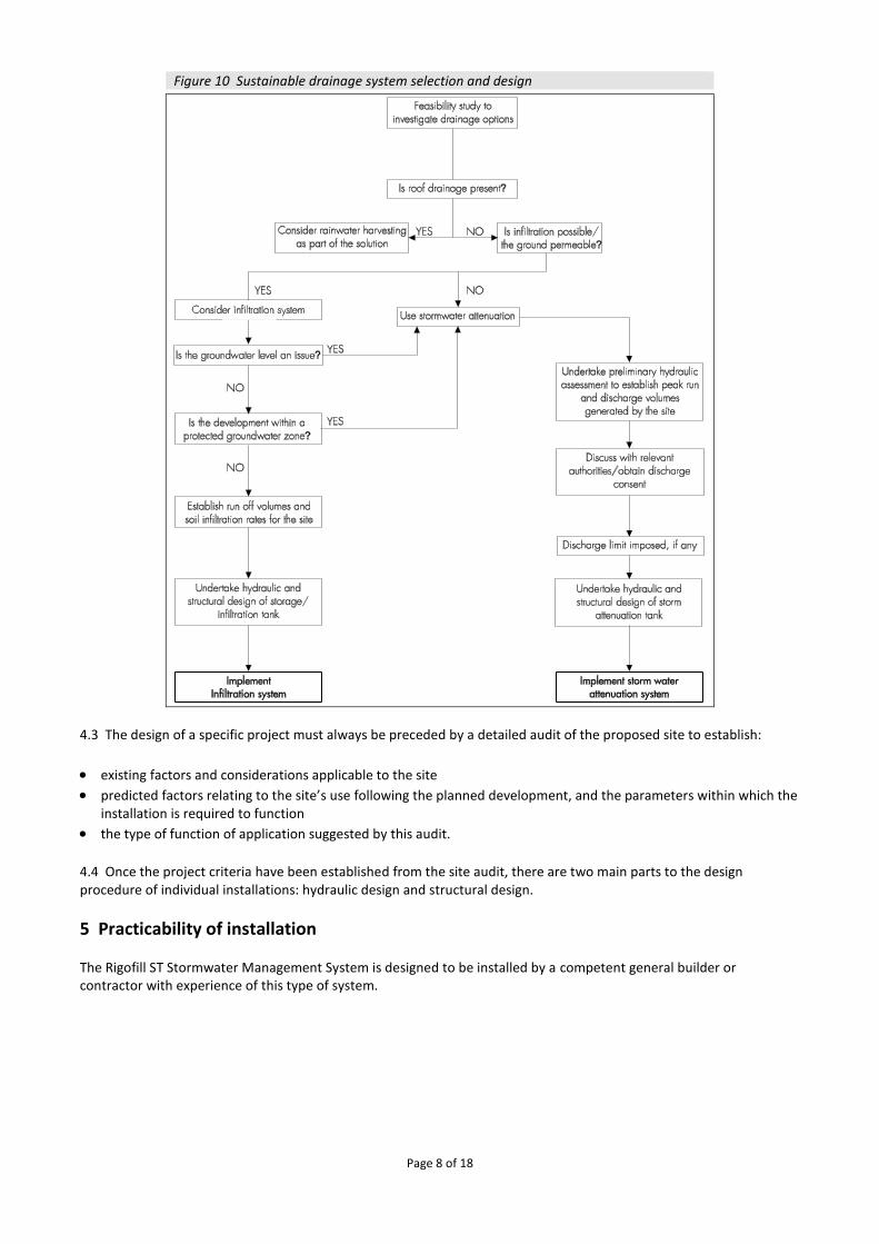
4 Use 4.1 Design of the system must be in accordance with the Certificate holder's design guidelines. Guidance on the application of sustainable drainage systems (SUDS) for new developments can be found in the Planning Policy Statement 25 Development and Flood Risk Practical Guide and The SUDS Manual published by the Construction Industry Research and Information Association (CIRIA), Report C697. 4.2 The system is satisfactory for the management of stormwater run-off from impermeable surfaces and can be utilised in three main ways (see Figure 10):
• infiltration — water is stored within the system during rainfall and allowed to drain away by infiltrating into the surrounding ground over a substantial period of time after the rain has stopped
• attenuation — water is stored within the system during rainfall and released at a reduced flow rate through a flow control device into an appropriate outfall. This reduces peak flows in the watercourse and, therefore, minimises the risk of flooding
• a combination of infiltration and attenuation.
Page 8 of 18
Figure 10 Sustainable drainage system selection and design
4.3 The design of a specific project must always be preceded by a detailed audit of the proposed site to establish:
• existing factors and considerations applicable to the site • predicted factors relating to the site’s use following the planned development, and the parameters within which the
installation is required to function
• the type of function of application suggested by this audit.
4.4 Once the project criteria have been established from the site audit, there are two main parts to the design procedure of individual installations: hydraulic design and structural design.
5 Practicability of installation The Rigofill ST Stormwater Management System is designed to be installed by a competent general builder or contractor with experience of this type of system.
Page 9 of 18
6 Hydraulic Design Infiltration Calculation principles
6.1 There are two approaches, either of which can be adopted: CIRIA Report 156 and BRE Digest 365. Further information on the design of SUDS may be obtained from The SUDS Manual.
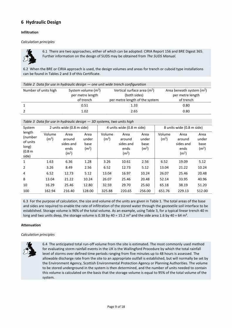
6.2 When the BRE or CIRIA approach is used, the design volumes and areas for trench or cuboid type installations can be found in Tables 2 and 3 of this Certificate.
Table 2 Data for use in hydraulic design — one unit wide trench configuration Number of units high System volume (m3)
per metre length of trench
Vertical surface area (m2) (both sides)
per metre length of the system
Area beneath system (m2) per metre length
of trench
1 0.51 1.33 0.80
2 1.02 2.65 0.80
Table 3 Data for use in hydraulic design — 3D systems, two units high
System length (number of units long) (0.8 m side)
2 units wide (0.8 m side) 4 units wide (0.8 m side) 8 units wide (0.8 m side)
Volume (m3)
Area around
sides and ends (m2)
Area under base (m2)
Volume (m3)
Area around
sides and ends (m2)
Area under base (m2)
Volume (m3)
Area around
sides and ends (m2)
Area under base (m2)
1 1.63 6.36 1.28 3.26 10.61 2.56 6.52 19.09 5.12
2 3.26 8.49 2.56 6.52 12.73 5.12 13.04 21.22 10.24
4 6.52 12.73 5.12 13.04 16.97 10.24 26.07 25.46 20.48
8 13.04 21.22 10.24 26.07 25.46 20.48 52.14 33.95 40.96
10 16.29 25.46 12.80 32.59 29.70 25.60 65.18 38.19 51.20
100 162.94 216.40 128.00 325.88 220.65 256.00 651.76 229.13 512.00
6.3 For the purpose of calculation, the size and volume of the units are given in Table 1. The total areas of the base and sides are required to enable the rate of infiltration of the stored water through the geotextile soil interface to be established. Storage volume is 96% of the total volume. As an example, using Table 3, for a typical linear trench 40 m long and two units deep, the storage volume is 0.38 by 40 = 15.2 m³ and the side area 1.6 by 40 = 64 m².
Attenuation Calculation principles
6.4 The anticipated total run-off volume from the site is estimated. The most commonly used method for evaluating storm rainfall events in the UK is the Wallingford Procedure by which the total rainfall level of storms over defined time periods ranging from five minutes up to 48 hours is assessed. The allowable discharge rate from the site to an appropriate outfall is established, but will normally be set by the Environment Agency, Scottish Environmental Protection Agency or Planning Authorities. The volume to be stored underground in the system is then determined, and the number of units needed to contain this volume is calculated on the basis that the storage volume is equal to 95% of the total volume of the system.
Page 10 of 18
Connections
6.5 Connection is made to the units using a pre-formed socket and adaptor or flange adaptor. It is recommended that all connections into storage applications (using a geomembrane) are made using a flange adaptor. Adhesive or double-sided tape should be used between the geomembrane and flange adaptor to ensure a watertight seal.
Manifold design
6.6 The units are manufactured to allow a connection to be formed by inserting 160 mm diameter pipes (to BS EN 1401-1 : 2009) into the convenient knock-out incorporated in each cell. The capacity of a 160 mm pipe is limited and may be insufficient for the anticipated design flow.
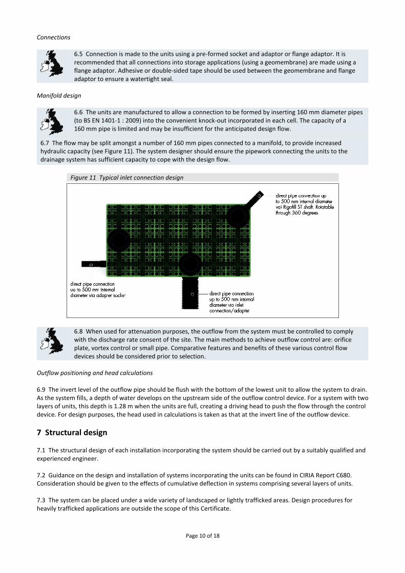
6.7 The flow may be split amongst a number of 160 mm pipes connected to a manifold, to provide increased hydraulic capacity (see Figure 11). The system designer should ensure the pipework connecting the units to the drainage system has sufficient capacity to cope with the design flow.
Figure 11 Typical inlet connection design
6.8 When used for attenuation purposes, the outflow from the system must be controlled to comply with the discharge rate consent of the site. The main methods to achieve outflow control are: orifice plate, vortex control or small pipe. Comparative features and benefits of these various control flow devices should be considered prior to selection.
Outflow positioning and head calculations 6.9 The invert level of the outflow pipe should be flush with the bottom of the lowest unit to allow the system to drain. As the system fills, a depth of water develops on the upstream side of the outflow control device. For a system with two layers of units, this depth is 1.28 m when the units are full, creating a driving head to push the flow through the control device. For design purposes, the head used in calculations is taken as that at the invert line of the outflow device.
7 Structural design 7.1 The structural design of each installation incorporating the system should be carried out by a suitably qualified and experienced engineer. 7.2 Guidance on the design and installation of systems incorporating the units can be found in CIRIA Report C680. Consideration should be given to the effects of cumulative deflection in systems comprising several layers of units. 7.3 The system can be placed under a wide variety of landscaped or lightly trafficked areas. Design procedures for heavily trafficked applications are outside the scope of this Certificate.
Page 11 of 18
7.4 Care should be taken when the system is used for infiltration below trafficked areas and close to structures. It is important to ensure that the infiltrating water will not soften the soils or cause loss of fines and settlement. 7.5 The engineer responsible for the design of the installation must confirm that the ground-bearing capacity at the formation level is sufficient for the proposed operational loads. In areas of weak or compressible soils, advice should be sought from a geotechnical engineer. 7.6 When the system is wrapped in an impermeable geomembrane and placed below the groundwater table, flotation may occur. To prevent this, the weight of the soil over the top of the units must be greater than the uplift force caused by the unit’s buoyancy in the water. This can be achieved with most types of fill if the depth of cover fill is equal to, or greater than, the depth of penetration of the units below groundwater level. Performance characteristics 7.7 Characteristic compressive strength at the yield point and elastic deflection values for the system have been determined from independent, short-term tests (see Table 4).
Table 4 Short-term performance values Performance characteristic Value
Characteristic compressive strength at the yield point (kN·m-2) vertical loading on top face lateral loading on side face
400 115
Short-term elastic deflection (mm per kN·m-2) (applied load) vertical loading on top face lateral loading on side face
1 per 67.73 1 per 18.52
7.8 Creep tests indicate that the long-term deflection may be estimated from the equations given in Table 5. This is valid for loads up to 108 kN·m–2, for durations of up to 50 years at 20°C.
Table 5 Equations for estimation of long-term deflection For loads up to (kN·m-2) Equation
60 Deflection = 0.2731 Ln [time (hours)] + 1.2857
108 Deflection = 0.4728 Ln [time (hours)] + 2.2418
7.9 The partial load and material factors given in Table 6, as defined in CIRIA Report C680, should be used for design.
Table 6 Partial factors for loads and materials Description Ultimate limit
state Serviceability
limit state
Partial factors for loads vertical dead-load (Fdl) earth pressure (horizontal) + hydrostatic (horizontal load (Fep) imposed live-load (Fll)
1.40 1.35 1.60
1.00 1.00 1.00
Partial safety factors for materials (Fm) 2.75 1.50
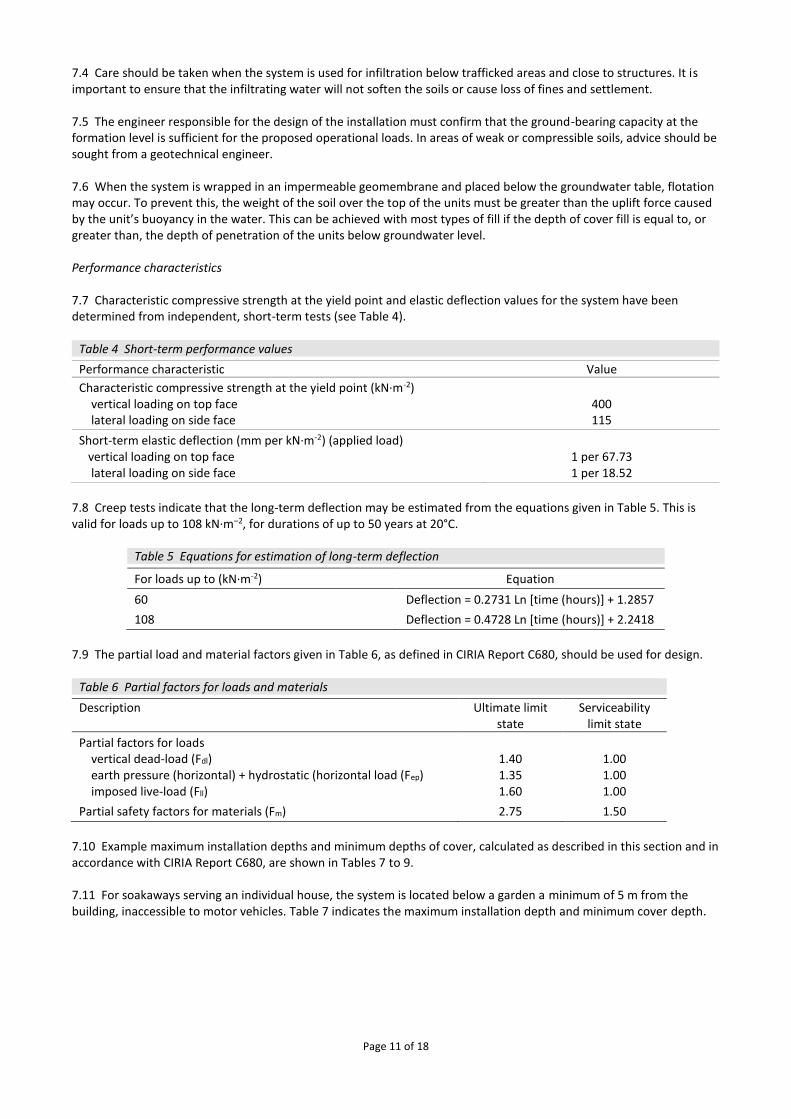
7.10 Example maximum installation depths and minimum depths of cover, calculated as described in this section and in accordance with CIRIA Report C680, are shown in Tables 7 to 9. 7.11 For soakaways serving an individual house, the system is located below a garden a minimum of 5 m from the building, inaccessible to motor vehicles. Table 7 indicates the maximum installation depth and minimum cover depth.
Page 12 of 18
Table 7 Design criteria for use of the system as a soakaway for an individual house(1) Criteria Value (m)
Maximum depth to base of units (m) 4.00
Minimum cover depth (m) 0.50
(1) The following assumptions apply:
• soakaway constructed in sandy gravels with a soil unit weight not exceeding 20 kg·m-3 and angle of internal friction for surrounding soil not less than 30°
• groundwater at least one metre below the base of the units
• soakaway located beneath small gardens or landscaped areas, no vehicles in accordance with Table 4.2 of CIRIA Report C680.
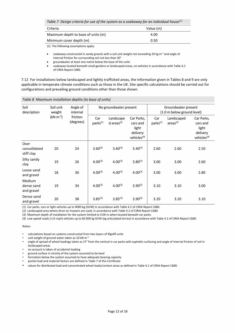
7.12 For installations below landscaped and lightly trafficked areas, the information given in Tables 8 and 9 are only applicable in temperate climate conditions such as those in the UK. Site specific calculations should be carried out for configurations and prevailing ground conditions other than those shown.
Table 8 Maximum installation depths (to base of units)
Soil description
Soil unit weight
(kN·m-3)
Angle of internal friction
(degrees)
No groundwater present Groundwater present (1.0 m below ground level)
Car parks(1)
Landscaped areas(2)
Car Parks, cars and
light delivery
vehicles(4)
Car parks(1)
Landscaped areas(2)
Car Parks, cars and
light delivery
vehicles(4)
Over consolidated stiff clay
20 24 3.60(3) 3.60(3) 3.40(3) 2.60 2.60 2.50
Silty sandy clay
19 26 4.00(3) 4.00(3) 3.80(3) 3.00 3.00 2.60
Loose sand and gravel
18 30 4.00(3) 4.00(3) 4.00(3) 3.00 3.00 2.80
Medium dense sand and gravel
19 34 4.00(3) 4.00(3) 3.90(3) 3.10 3.10 3.00
Dense sand and gravel
20 38 3.85(3) 3.85(3) 3.90(3) 3.20 3.20 3.10
(1) Car parks, cars or light vehicles up to 9000 kg (GVW) in accordance with Table 4.2 of CIRIA Report C680. (2) Landscaped area where drive on mowers are used, in accordance with Table 4.2 of CIRIA Report C680. (3) Maximum depth of installation for the system limited to 4.00 m when located beneath car parks. (4) Low speed roads (<15 mph) vehicles up to 60 000 kg GVW (eg articulated lorries) in accordance with Table 4.2 of CIRIA Report C680. Notes: • calculations based on systems constructed from two layers of Rigofill units • unit weight of ground water taken as 10 kN·m-3 • angle of spread of wheel loadings taken as 27° from the vertical in car parks with asphaltic surfacing and angle of internal friction of soil in
landscaped areas • no account is taken of accidental loading • ground surface in vicinity of the system assumed to be level • formation below the system assumed to have adequate bearing capacity • partial load and material factors are defined in Table 7 of this Certificate
• values for distributed load and concentrated wheel loads/contact areas as defined in Table 4.1 of CIRIA Report C680.
Page 13 of 18
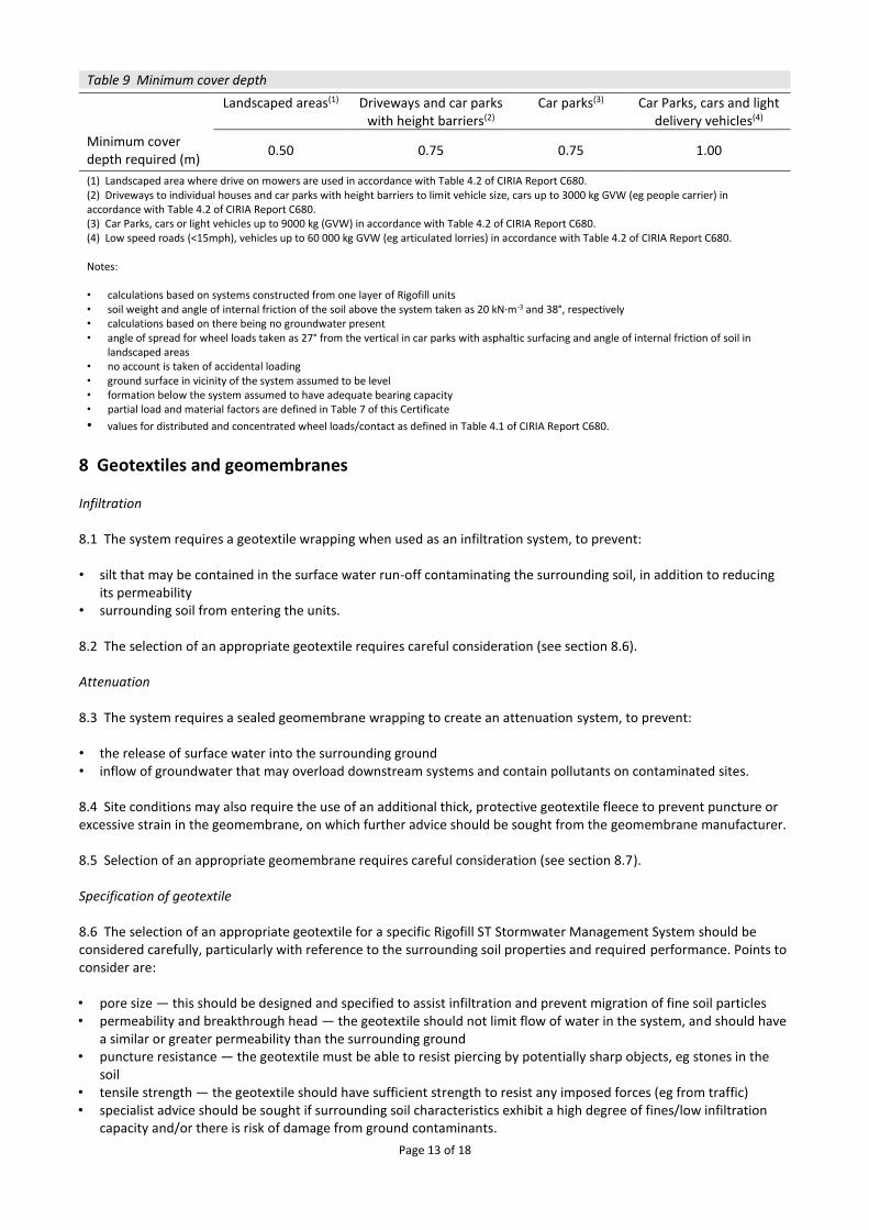
Table 9 Minimum cover depth Landscaped areas(1) Driveways and car parks
with height barriers(2) Car parks(3) Car Parks, cars and light
delivery vehicles(4)
Minimum cover depth required (m)
0.50 0.75 0.75 1.00
(1) Landscaped area where drive on mowers are used in accordance with Table 4.2 of CIRIA Report C680. (2) Driveways to individual houses and car parks with height barriers to limit vehicle size, cars up to 3000 kg GVW (eg people carrier) in accordance with Table 4.2 of CIRIA Report C680. (3) Car Parks, cars or light vehicles up to 9000 kg (GVW) in accordance with Table 4.2 of CIRIA Report C680. (4) Low speed roads (<15mph), vehicles up to 60 000 kg GVW (eg articulated lorries) in accordance with Table 4.2 of CIRIA Report C680. Notes: • calculations based on systems constructed from one layer of Rigofill units • soil weight and angle of internal friction of the soil above the system taken as 20 kN·m-3 and 38°, respectively • calculations based on there being no groundwater present • angle of spread for wheel loads taken as 27° from the vertical in car parks with asphaltic surfacing and angle of internal friction of soil in
landscaped areas • no account is taken of accidental loading • ground surface in vicinity of the system assumed to be level • formation below the system assumed to have adequate bearing capacity • partial load and material factors are defined in Table 7 of this Certificate
• values for distributed and concentrated wheel loads/contact as defined in Table 4.1 of CIRIA Report C680.
8 Geotextiles and geomembranes Infiltration 8.1 The system requires a geotextile wrapping when used as an infiltration system, to prevent: • silt that may be contained in the surface water run-off contaminating the surrounding soil, in addition to reducing
its permeability • surrounding soil from entering the units. 8.2 The selection of an appropriate geotextile requires careful consideration (see section 8.6). Attenuation 8.3 The system requires a sealed geomembrane wrapping to create an attenuation system, to prevent: • the release of surface water into the surrounding ground • inflow of groundwater that may overload downstream systems and contain pollutants on contaminated sites.
8.4 Site conditions may also require the use of an additional thick, protective geotextile fleece to prevent puncture or excessive strain in the geomembrane, on which further advice should be sought from the geomembrane manufacturer. 8.5 Selection of an appropriate geomembrane requires careful consideration (see section 8.7). Specification of geotextile 8.6 The selection of an appropriate geotextile for a specific Rigofill ST Stormwater Management System should be considered carefully, particularly with reference to the surrounding soil properties and required performance. Points to consider are: • pore size — this should be designed and specified to assist infiltration and prevent migration of fine soil particles • permeability and breakthrough head — the geotextile should not limit flow of water in the system, and should have
a similar or greater permeability than the surrounding ground • puncture resistance — the geotextile must be able to resist piercing by potentially sharp objects, eg stones in the
soil • tensile strength — the geotextile should have sufficient strength to resist any imposed forces (eg from traffic) • specialist advice should be sought if surrounding soil characteristics exhibit a high degree of fines/low infiltration
capacity and/or there is risk of damage from ground contaminants.
Page 14 of 18
Specification of geomembrane 8.7 The specification and selection of the impermeable geomembrane must be correct for the proposed installation, to ensure it performs to the level required. It is essential that the specified material: • withstands the rigours of installation • resists puncture • resists multi-axial elongation stress and strains associated with settlement • resists environmental stress cracking • resists damage from ground contaminants • remains intact for the full design life. 8.8 A geomembrane less than 1 mm thick is unlikely to meet these criteria (except in shallow, domestic installations), and is not recommended for use with the Rigofill ST Block. For further details the Certificate holder’s advice should be sought. 8.9 All joints must be sealed, using proprietary techniques recommended by the manufacturer. Advice on seam testing procedures is given in CIRIA SP 124 : 1996.
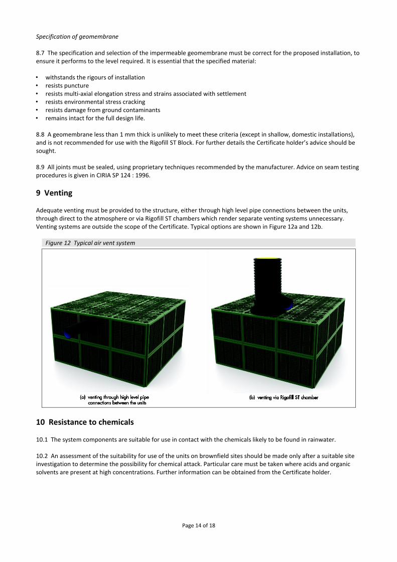
9 Venting Adequate venting must be provided to the structure, either through high level pipe connections between the units, through direct to the atmosphere or via Rigofill ST chambers which render separate venting systems unnecessary. Venting systems are outside the scope of the Certificate. Typical options are shown in Figure 12a and 12b.
Figure 12 Typical air vent system
10 Resistance to chemicals 10.1 The system components are suitable for use in contact with the chemicals likely to be found in rainwater. 10.2 An assessment of the suitability for use of the units on brownfield sites should be made only after a suitable site investigation to determine the possibility for chemical attack. Particular care must be taken where acids and organic solvents are present at high concentrations. Further information can be obtained from the Certificate holder.
Page 15 of 18
11 Maintenance
11.1 The owner of the structure is responsible for its maintenance.
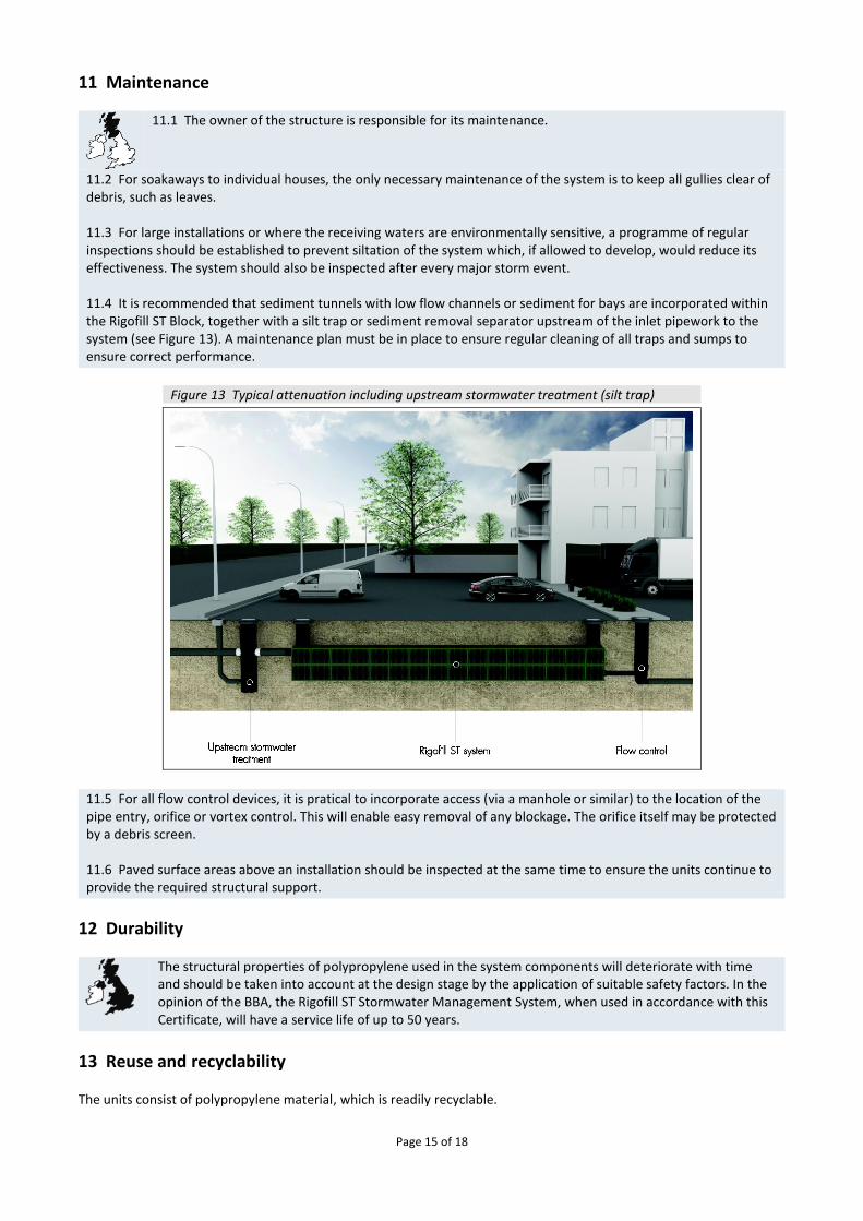
11.2 For soakaways to individual houses, the only necessary maintenance of the system is to keep all gullies clear of debris, such as leaves. 11.3 For large installations or where the receiving waters are environmentally sensitive, a programme of regular inspections should be established to prevent siltation of the system which, if allowed to develop, would reduce its effectiveness. The system should also be inspected after every major storm event. 11.4 It is recommended that sediment tunnels with low flow channels or sediment for bays are incorporated within the Rigofill ST Block, together with a silt trap or sediment removal separator upstream of the inlet pipework to the system (see Figure 13). A maintenance plan must be in place to ensure regular cleaning of all traps and sumps to ensure correct performance.
Figure 13 Typical attenuation including upstream stormwater treatment (silt trap)
11.5 For all flow control devices, it is pratical to incorporate access (via a manhole or similar) to the location of the pipe entry, orifice or vortex control. This will enable easy removal of any blockage. The orifice itself may be protected by a debris screen. 11.6 Paved surface areas above an installation should be inspected at the same time to ensure the units continue to provide the required structural support.
12 Durability
The structural properties of polypropylene used in the system components will deteriorate with time and should be taken into account at the design stage by the application of suitable safety factors. In the opinion of the BBA, the Rigofill ST Stormwater Management System, when used in accordance with this Certificate, will have a service life of up to 50 years.
13 Reuse and recyclability The units consist of polypropylene material, which is readily recyclable.
Page 16 of 18
Installation
14 General The Rigofill ST Stormwater Management System should be installed in accordance with the Certificate holder’s Installation manual Infiltration systems and waterthight storage systems with Rigofill ST and this Certificate. Special attention should be paid to temporary work requirements in excavations.
15 Procedure 15.1 The hole or trench is excavated to the required depth, dimensions and levels. It must be ensured that the plan area is sufficient to allow plant access around sides to compact backfill material (300 mm minimum). The base must be smooth and level without sharp drops or humps. Slopes must be cut to a safe angle or adequately supported and safe access must be provided to allow personnel to enter the excavation. Excavation must be carried out in accordance with BS 6031 : 2009, with particular attention paid to safety procedures. 15.2 The base must be inspected for soft spots in the formation, any present must be excavated and replaced with compacted granular fill material. 15.3 A 100 mm thick, bedding layer of coarse sand is laid on the base and sides of the excavation. If required in attenuation systems, a layer of geotextile is laid to protect the impermeable geomembrane. 15.4 The impermeable geomembrane (or geotextile, if in an infiltration system) is laid over the sand bedding layer and up the sides of the excavation. The impermeable geomembrane is inspected for damage and all welds are tested as required. Joints between adjacent sheets of impermeable membrane should be sealed correctly using proprietary techniques with a minimum lap of 50 mm. Jointing with tape is not recommended as the system then becomes reliant on the mechanical properties of the tape to maintain its integrity. 15.5 The units are installed in accordance with the installation schedule for correct orientation. For single-layer applications, horizontal connection pieces are used and for multiple layer systems, multi-layer connection pieces are used. 15.6 The geotextile or impermeable geomembrane encapsulation to base, sides and top of installation, including protective geotextile (if required to protect the geomembrane) is completed. Impermeable geomembranes should be welded with double seams. All welds should be tested as required and the membrane inspected for damage. 15.7 Drainage connections are made to the installation using proprietary adaptors. Pre-formed socket positions for pipe connections must be located at the correct position for receiving pipework. Alternatively, flange adaptors are used attached to the units with adhesive tape and self-tapping screws (flange adaptors cannot be used at the invert of the units into the pre-formed socket). It is recommended that all connections and air vent installations, in attenuation applications, are made with a flange adaptor, using adhesive or double-sided tape to form a seal. Alternatively, drainage connections are sealed into a pre-formed socket using proprietary seals approved by the geomembrane manufacturer. 15.8 The installation is backfilled with Type 1 or 2 sub-base or Class 6P (side fill only) selected granular material in accordance with the Manual of Contract Documents for Highway Works (MCHW), Volume 1 Specification for Highway Works (SHW). The backfill is compacted in 150 mm thick layers. 15.9 A coarse sand protection layer, 100 mm thick, should be placed over the top of the units that have been wrapped. Backfilling is continued with: • trafficked areas (eg car parks) — Type 1 or 2 sub-base material compacted in 150 mm layers in accordance with the
MCHW, Volume 1. The mass of compaction plant over the top of the system must not exceed 2300 kg per metre width of roll
• landscaped and non-trafficked areas — selected as-dug material, with size of pieces less than 75 mm, compacted to 90% maximum dry density. The mass of compaction plant over the top of the system must not exceed 2300 kg per metre width of roll.
15.10 Pavement construction or landscaping over the system can be completed.

Page 17 of 18
Technical Investigations
16 Tests Tests were carried out on the system and the results assessed to determine:
• long- and short-term resistance to loading
• volumetric capacity and discharge rate.
17 Investigations 17.1 The manufacturing process was evaluated, including the methods adopted for quality control, and details were obtained of the quality and composition of the materials used. 17.2 An assessment of the system was made in relation to material properties and design procedures. 17.3 A site visit was made to assess the practicability and ease of installation and connection.
Bibliography BRE Digest 365 Soakaway Design BS 6031 : 2009 Code of practice for earthworks BS EN 1401-1 : 2009 Plastics piping systems for non-pressure underground drainage and sewerage — Unplasticized poly(vinylchloride) (PVC-U) — Specifications for pipes, fittings and the system BS EN ISO 9001 : 2000 Quality management systems — Requirements CIRIA C697 : The SUDS Manual CIRIA Report 156 Infiltration drainage — Manual of good practice CIRIA C680 : Structural design of modular geocellular drainage tanks CIRIA Report SP 124 : 1996 Barriers, liners and cover systems for containment and control of land contamination Manual of Contract Documents for Highway Works, Volume 1 Specification for Highway Works

Page 18 of 18
Conditions of Certification
18 Conditions 18.1 This Certificate:
• relates only to the product/system that is named and described on the front page
• is issued only to the company, firm, organisation or person named on the front page – no other company, firm, organisation or person may hold claim that this Certificate has been issued to them
• is valid only within the UK
• has to be read, considered and used as a whole document – it may be misleading and will be incomplete to be selective
• is copyright of the BBA
• is subject to English Law. 18.2 Publications, documents, specifications, legislation, regulations, standards and the like referenced in this Certificate are those that were current and/or deemed relevant by the BBA at the date of issue or reissue of this Certificate. 18.3 This Certificate will remain valid for an unlimited period provided that the product/system and its manufacture and/or fabrication, including all related and relevant parts and processes thereof:
• are maintained at or above the levels which have been assessed and found to be satisfactory by the BBA
• continue to be checked as and when deemed appropriate by the BBA under arrangements that it will determine
• are reviewed by the BBA as and when it considers appropriate. 18.4 The BBA has used due skill, care and diligence in preparing this Certificate, but no warranty is provided. 18.5 In issuing this Certificate the BBA is not responsible and is excluded from any liability to any company, firm, organisation or person, for any matters arising directly or indirectly from:
• the presence or absence of any patent, intellectual property or similar rights subsisting in the product/system or any other product/system
• the right of the Certificate holder to manufacture, supply, install, maintain or market the product/system
• actual installations of the product/system, including their nature, design, methods, performance, workmanship and maintenance
• any works and constructions in which the product/system is installed, including their nature, design, methods, performance, workmanship and maintenance
• any loss or damage, including personal injury, howsoever caused by the product/system, including its manufacture, supply, installation, use, maintenance and removal
• any claims by the manufacturer relating to CE marking. 18.6 Any information relating to the manufacture, supply, installation, use, maintenance and removal of this product/system which is contained or referred to in this Certificate is the minimum required to be met when the product/system is manufactured, supplied, installed, used, maintained and removed. It does not purport in any way to restate the requirements of the Health and Safety at Work etc. Act 1974, or of any other statutory, common law or other duty which may exist at the date of issue or reissue of this Certificate; nor is conformity with such information to be taken as satisfying the requirements of the 1974 Act or of any statutory, common law or other duty of care.
British Board of Agrément Bucknalls Lane Watford Herts WD25 9BA
©2018
tel: 01923 665300
[email protected] www.bbacerts.co.uk