Embed Size (px)
Citation preview
Air-ConditionersSLZ-KA25, KA35, KA50VA
KA25, KA35, KA50VALSEZ-KA35, KA50, KA60, KA71VA
OPERATION MANUALFor safe and correct use, please read this operation manual thoroughly before operating the air-conditioner unit.
BEDIENUNGSHANDBUCHZum sicheren und einwandfreien Gebrauch der Klimaanlage dieses Bedienungshandbuch vor Inbetriebnahmegründlich durchlesen.
MANUEL D’UTILISATIONPour une utilisation correcte sans risques, veuillez lire le manuel d’utilisation en entier avant de vous servir duclimatiseur.
DRIFTSMANUALLäs denna driftsmanual noga för säkert och korrekt bruk innan luftkonditioneringen används.
BEDIENINGSHANDLEIDINGVoor een veilig en juist gebruik moet u deze bedieningshandleiding grondig doorlezen voordat u deairconditioner gebruikt.
ISTRUZIONI DI FUNZIONAMENTOLeggere attentamente questi istruzioni di funzionamento prima di avviare l’unità, per un uso corretto e sicurodella stessa.
MANUAL DE INSTRUCCIONESLea este manual de instrucciones hasta el final antes de poner en marcha la unidad de aire acondicionadopara garantizar un uso seguro y correcto.
MANUAL DE OPERAÇÃOPara segurança e utilização correctas, leia atentamente o manual de operação antes de pôr a funcionar aunidade de ar condicionado.
E°XEIPI¢IO O¢H°IøN XPH™Eø™°È· ·ÛÊ¿ÏÂÈ· Î·È ÛˆÛÙ‹ ¯Ú‹ÛË, ·Ú·Î·Ï›ÛÙ ‰È·‚¿ÛÂÙ ÚÔÛ¯ÙÈο ·˘Ùfi ÙÔ ÂÁ¯ÂÈÚ›‰ÈÔ ¯Ú‹Ûˆ˜ ÚÈÓ ı¤ÛÂÙ ÛÂÏÂÈÙÔ˘ÚÁ›· ÙË ÌÔÓ¿‰· ÎÏÈÌ·ÙÈÛÌÔ‡.
FOR USER
FÜR BENUTZER
POUR L’UTILISATEUR
FÖR ANVÄNDAREN
VOOR DE GEBRUIKER
PER L’UTENTE
PARA EL USUARIO
PARA O UTILIZADOR
°π∞ ∆√¡ Ã∏™∆∏
English
Deutsch
Français
Nederlands
Español
Italiano
∂ÏÏËÓÈο
Português
Svenska
2
1. Safety Precautions ................................................................ 22. Parts Names ......................................................................... 23. Screen Configuration ............................................................ 54. Setting the Day of the Week and Time.................................. 55. Operation .............................................................................. 56. Timer ..................................................................................... 7
Contents
s Before installing the unit, make sure you read all the “SafetyPrecautions”.
s The “Safety Precautions” provide very important points regard-ing safety. Make sure you follow them.
s Please report to or take consent by the supply authority be-fore connection to the system.
1. Safety Precautions
2. Parts Names
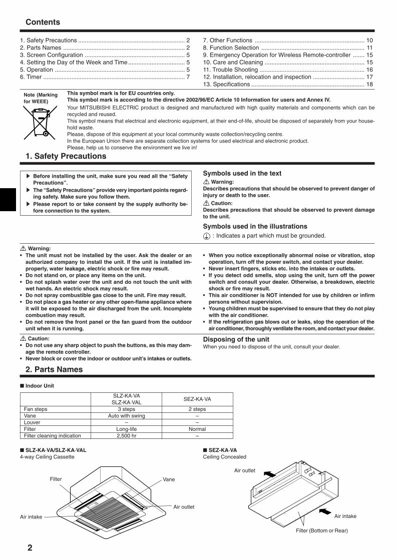
� Indoor Unit
SLZ-KA·VASEZ-KA·VA
SLZ-KA·VALFan steps 3 steps 2 stepsVane Auto with swing –Louver – –Filter Long-life NormalFilter cleaning indication 2,500 hr –
7. Other Functions .................................................................. 108. Function Selection .............................................................. 119. Emergency Operation for Wireless Remote-controller ....... 1510. Care and Cleaning ............................................................ 1511. Trouble Shooting ............................................................... 1612. Installation, relocation and inspection ............................... 1713. Specifications .................................................................... 18
This symbol mark is for EU countries only.This symbol mark is according to the directive 2002/96/EC Article 10 Information for users and Annex IV.Your MITSUBISHI ELECTRIC product is designed and manufactured with high quality materials and components which can berecycled and reused.This symbol means that electrical and electronic equipment, at their end-of-life, should be disposed of separately from your house-hold waste.Please, dispose of this equipment at your local community waste collection/recycling centre.In the European Union there are separate collection systems for used electrical and electronic product.Please, help us to conserve the environment we live in!
Symbols used in the text Warning:
Describes precautions that should be observed to prevent danger ofinjury or death to the user.
Caution:Describes precautions that should be observed to prevent damageto the unit.
Symbols used in the illustrations: Indicates a part which must be grounded.
Warning:• The unit must not be installed by the user. Ask the dealer or an
authorized company to install the unit. If the unit is installed im-properly, water leakage, electric shock or fire may result.
• Do not stand on, or place any items on the unit.• Do not splash water over the unit and do not touch the unit with
wet hands. An electric shock may result.• Do not spray combustible gas close to the unit. Fire may result.• Do not place a gas heater or any other open-flame appliance where
it will be exposed to the air discharged from the unit. Incompletecombustion may result.
• Do not remove the front panel or the fan guard from the outdoorunit when it is running.
• When you notice exceptionally abnormal noise or vibration, stopoperation, turn off the power switch, and contact your dealer.
• Never insert fingers, sticks etc. into the intakes or outlets.• If you detect odd smells, stop using the unit, turn off the power
switch and consult your dealer. Otherwise, a breakdown, electricshock or fire may result.
• This air conditioner is NOT intended for use by children or infirmpersons without supervision.
• Young children must be supervised to ensure that they do not playwith the air conditioner.
• If the refrigeration gas blows out or leaks, stop the operation of theair conditioner, thoroughly ventilate the room, and contact your dealer.
Caution:• Do not use any sharp object to push the buttons, as this may dam-
age the remote controller.• Never block or cover the indoor or outdoor unit’s intakes or outlets.
Disposing of the unitWhen you need to dispose of the unit, consult your dealer.
Note (Markingfor WEEE)
� SLZ-KA·VA/SLZ-KA·VAL4-way Ceiling Cassette
Filter
Air intake
Vane
Air outlet
� SEZ-KA·VACeiling Concealed
Air outlet
Air intake
Filter (Bottom or Rear)
3
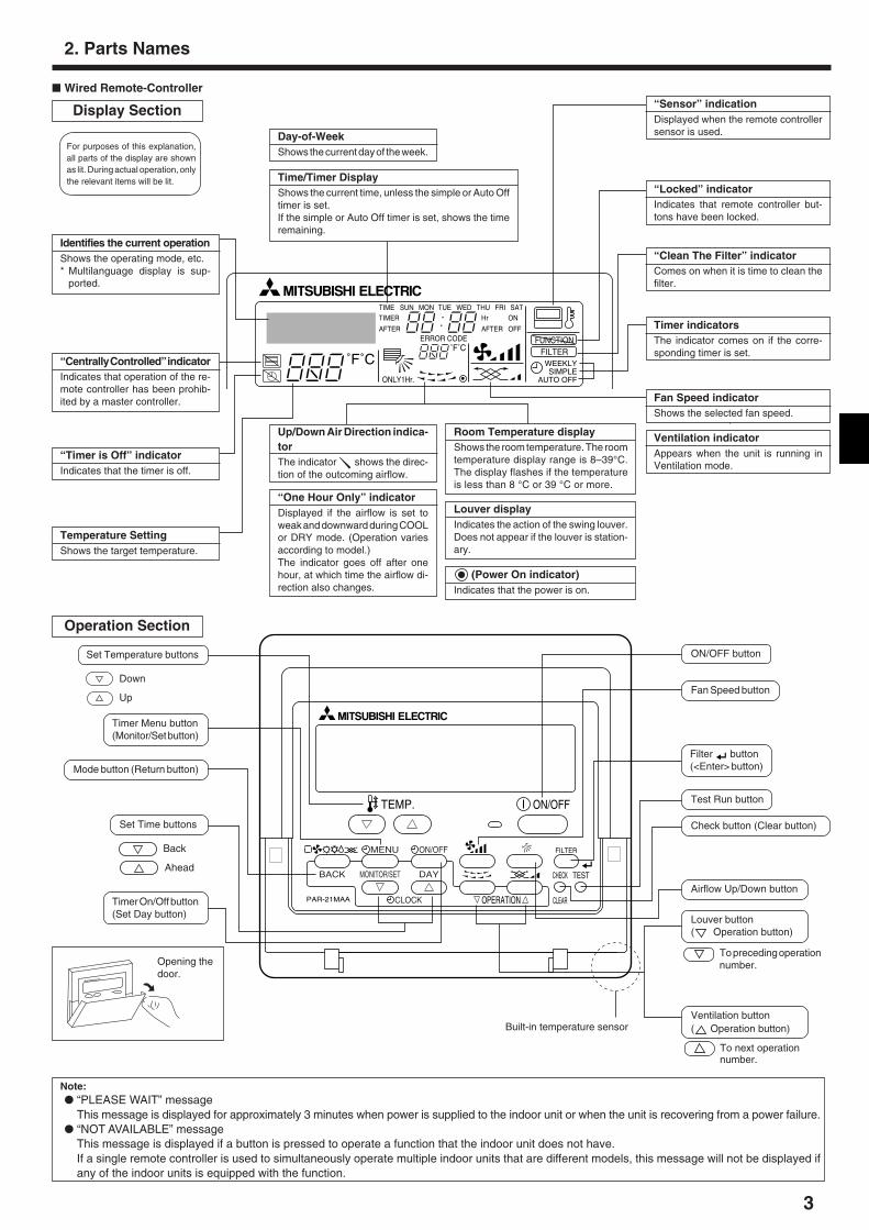
� Wired Remote-Controller
Display Section
For purposes of this explanation,all parts of the display are shownas lit. During actual operation, onlythe relevant items will be lit.
˚F˚C
˚F˚C
ERROR CODEAFTER
TIMERTIME SUN MON TUE WED THU FRI SAT
ON
OFF
Hr
AFTER
FILTERFUNCTION
ONLY1Hr.
WEEKLYSIMPLE
AUTO OFF
Identifies the current operationShows the operating mode, etc.* Multilanguage display is sup-
ported.
“Centrally Controlled” indicatorIndicates that operation of the re-mote controller has been prohib-ited by a master controller.
“Timer is Off” indicatorIndicates that the timer is off.
Temperature SettingShows the target temperature.
Day-of-WeekShows the current day of the week.
Time/Timer DisplayShows the current time, unless the simple or Auto Offtimer is set.If the simple or Auto Off timer is set, shows the timeremaining.
“Sensor” indicationDisplayed when the remote controllersensor is used.
“Locked” indicatorIndicates that remote controller but-tons have been locked.
“Clean The Filter” indicatorComes on when it is time to clean thefilter.
Timer indicatorsThe indicator comes on if the corre-sponding timer is set.
Up/Down Air Direction indica-torThe indicator shows the direc-tion of the outcoming airflow.
“One Hour Only” indicatorDisplayed if the airflow is set toweak and downward during COOLor DRY mode. (Operation variesaccording to model.)The indicator goes off after onehour, at which time the airflow di-rection also changes.
Room Temperature displayShows the room temperature. The roomtemperature display range is 8–39°C.The display flashes if the temperatureis less than 8 °C or 39 °C or more.
Louver displayIndicates the action of the swing louver.Does not appear if the louver is station-ary.
(Power On indicator)Indicates that the power is on.
Fan Speed indicatorShows the selected fan speed.
Ventilation indicatorAppears when the unit is running inVentilation mode.
Operation Section
PAR-21MAA
ON/OFF
FILTER
CHECK
OPERATION CLEAR
TEST
TEMP.
MENU
BACK DAYMONITOR/SET
CLOCK
ON/OFF
Set Temperature buttons
Down
Up
Timer Menu button(Monitor/Set button)
Mode button (Return button)
Set Time buttons
Back
Ahead
Timer On/Off button(Set Day button)
Opening thedoor.
ON/OFF button
Fan Speed button
Filter button(<Enter> button)
Test Run button
Check button (Clear button)
Airflow Up/Down button
Louver button( Operation button)
To preceding operationnumber.
Ventilation button( Operation button)
To next operationnumber.
2. Parts Names
Built-in temperature sensor
Note:� “PLEASE WAIT” message
This message is displayed for approximately 3 minutes when power is supplied to the indoor unit or when the unit is recovering from a power failure.� “NOT AVAILABLE” message
This message is displayed if a button is pressed to operate a function that the indoor unit does not have.If a single remote controller is used to simultaneously operate multiple indoor units that are different models, this message will not be displayed ifany of the indoor units is equipped with the function.
4
1
23
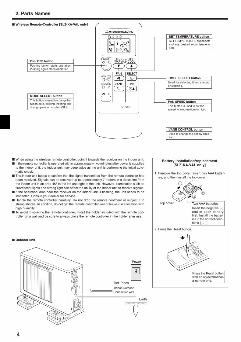
� Wireless Remote-Controller [SLZ-KA·VAL only]
� Outdoor unit
Power
Earth
Indoor-OutdoorConnection wire
Ref. Pipes
2. Parts Names
� When using the wireless remote controller, point it towards the receiver on the indoor unit.� If the remote controller is operated within approximately two minutes after power is supplied
to the indoor unit, the indoor unit may beep twice as the unit is performing the initial auto-matic check.
� The indoor unit beeps to confirm that the signal transmitted from the remote controller hasbeen received. Signals can be received up to approximately 7 meters in a direct line fromthe indoor unit in an area 45° to the left and right of the unit. However, illumination such asfluorescent lights and strong light can affect the ability of the indoor unit to receive signals.
� If the operation lamp near the receiver on the indoor unit is flashing, the unit needs to beinspected. Consult your dealer for service.
� Handle the remote controller carefully! Do not drop the remote controller or subject it tostrong shocks. In addition, do not get the remote controller wet or leave it in a location withhigh humidity.
� To avoid misplacing the remote controller, install the holder included with the remote con-troller on a wall and be sure to always place the remote controller in the holder after use.
Battery installation/replacement[SLZ-KA·VAL only]
1. Remove the top cover, insert two AAA batter-ies, and then install the top cover.
Top cover
Press the Reset buttonwith an object that hasa narrow end.
2. Press the Reset button.
AUTOCOOLDRY
HEAT
FANVANE SELECTTIM
E
ON/OFF
RESET
TOOWARM
TOOCOOL
MODE
AUTO COOL
DRYHEAT
FAN
VANE
SELECT
TIME
h
ON / OFF buttonPushing button starts operation.Pushing again stops operation.
MODE SELECT buttonThis button is used to change be-tween auto, cooling, heating anddrying operation modes. (SLZ)
SET TEMPERATURE buttonSET TEMPERATURE button setsand any desired room tempera-ture.
TIMER SELECT buttonUsed for selecting timed startingor stopping.
FAN SPEED buttonThis button is used to set fanspeed to low, medium or high.
VANE CONTROL buttonUsed to change the airflow direc-tion.
Two AAA batteriesInsert the negative (–)end of each batteryfirst. Install the batter-ies in the correct direc-tions (+, –)!
5
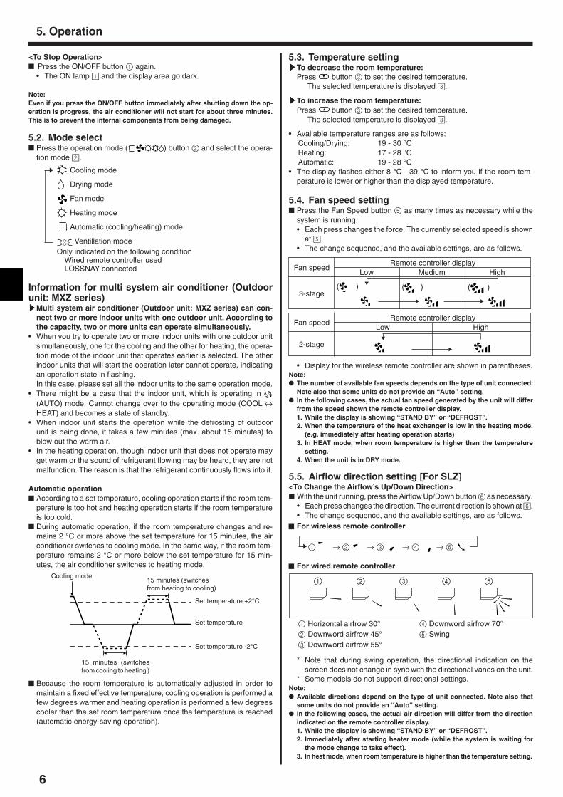
Note:� The day and time will not appear if clock use has been disabled at Function
Selection of remote controller.� After the power supply returns, the indoor unit does not operate for three
minutes. Above operation is normal.
Day of the Week &Time display
˚C
˚C
TIME SUN
PAR-21MAA
ON/OFF
FILTER
CHECK
OPERATION CLEAR
TEST
TEMP.
MENU
BACK DAYMONITOR/SET
CLOCK
ON/OFF
2 4
9
1
A
1. Press the or Set Time button A to show display 2.2. Press the Timer On/Off (Set Day) button 9 to set the day.
*Each press advances the day shown at 3 : Sun → Mon → ... → Fri →Sat.
3. Press the appropriate Set Time button A as necessary to set the time.*As you hold the button down, the time (at 4) will increment first inminute intervals, then in ten-minute intervals, and then in one-hour in-tervals.
4. After making the appropriate settings at Steps 2 and 3, press the Filter button 4 to lock in the values.
Time SettingTIME SUN2
3
4
Day of the Week Setting
4. Setting the Day of the Week and Time
˚C
˚C
PAR-21MAA
ON/OFF
FILTER
CHECK
OPERATION CLEAR
TEST
TEMP.
MENU
BACK DAYMONITOR/SET
CLOCK
ON/OFF
2
7
2
33
8
6
4
5
8
7
1
1
5
6
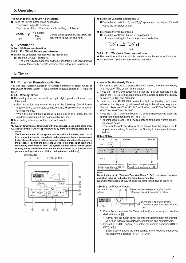
ModeTemperature settingFan speed
Airflow up/down
Remote Controller settingsLast operation modeLast set temperatureLast set fan speed
COOL or DRYMode HEAT
FAN
Horiz. outletLast settingHoriz. outlet
5.1. Turning ON/OFF<To Start Operation>� Press the ON/OFF button 1.
• The ON lamp 1 and the display area come on.Note:� When the unit is restarted, initial settings are as follows.
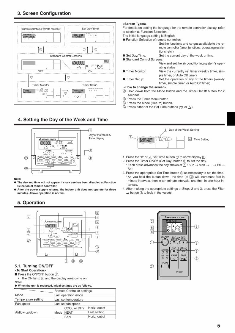
<Screen Types>For details on setting the language for the remote controller display, referto section 8. Function Selection.The initial language setting is English.� Function Selection of remote controller:
Set the functions and ranges available to the re-mote controller (timer functions, operating restric-tions, etc.)
� Set Day/Time: Set the current day of the week or time.� Standard Control Screens:
View and set the air conditioning system’s oper-ating status
� Timer Monitor: View the currently set timer (weekly timer, sim-ple timer, or Auto Off timer)
� Timer Setup: Set the operation of any of the timers (weeklytimer, simple timer, or Auto Off timer).
<How to change the screen>A :Hold down both the Mode button and the Timer On/Off button for 2
seconds.B :Press the Timer Menu button.C :Press the Mode (Return) button.D :Press either of the Set Time buttons ( or ).
˚F˚C
TIMERMON
OFF
WEEKLY
SUN MON TUE WED THU FRI SAT
WEEKLY
˚F˚C
˚C
TIME SUN
Function Selection of remote controller Set Day/Time
Standard Control Screens
OFF ON
Timer Monitor Timer Setup
A D C
B C
B
3. Screen Configuration
5. Operation
ON/OFF
RESET
TOOWARM
TOOCOOL
MODE
AUTO COOL
DRYHEAT
FAN
VANE
SELECT
TIME
h
1
2
56
3
3
5
6
2
6
5. Operation
<To Stop Operation>� Press the ON/OFF button 1 again.
• The ON lamp 1 and the display area go dark.
Note:Even if you press the ON/OFF button immediately after shutting down the op-eration is progress, the air conditioner will not start for about three minutes.This is to prevent the internal components from being damaged.
5.2. Mode select� Press the operation mode ( ) button 2 and select the opera-
tion mode 2.
Cooling mode
Drying mode
Fan mode
Heating mode
Automatic (cooling/heating) mode
Ventillation modeOnly indicated on the following condition
Wired remote controller usedLOSSNAY connected
Information for multi system air conditioner (Outdoorunit: MXZ series)sssssMulti system air conditioner (Outdoor unit: MXZ series) can con-
nect two or more indoor units with one outdoor unit. According tothe capacity, two or more units can operate simultaneously.
• When you try to operate two or more indoor units with one outdoor unitsimultaneously, one for the cooling and the other for heating, the opera-tion mode of the indoor unit that operates earlier is selected. The otherindoor units that will start the operation later cannot operate, indicatingan operation state in flashing.In this case, please set all the indoor units to the same operation mode.
• There might be a case that the indoor unit, which is operating in (AUTO) mode. Cannot change over to the operating mode (COOL ↔HEAT) and becomes a state of standby.
• When indoor unit starts the operation while the defrosting of outdoorunit is being done, it takes a few minutes (max. about 15 minutes) toblow out the warm air.
• In the heating operation, though indoor unit that does not operate mayget warm or the sound of refrigerant flowing may be heard, they are notmalfunction. The reason is that the refrigerant continuously flows into it.
Automatic operation� According to a set temperature, cooling operation starts if the room tem-
perature is too hot and heating operation starts if the room temperatureis too cold.
� During automatic operation, if the room temperature changes and re-mains 2 °C or more above the set temperature for 15 minutes, the airconditioner switches to cooling mode. In the same way, if the room tem-perature remains 2 °C or more below the set temperature for 15 min-utes, the air conditioner switches to heating mode.
s
Cooling mode15 minutes (switchesfrom heating to cooling)
Set temperature +2°C
Set temperature
Set temperature -2°C
15 minutes (switchesfrom cooling to heating )
� Because the room temperature is automatically adjusted in order tomaintain a fixed effective temperature, cooling operation is performed afew degrees warmer and heating operation is performed a few degreescooler than the set room temperature once the temperature is reached(automatic energy-saving operation).
5.3. Temperature settingsssssTo decrease the room temperature:
Press button 3 to set the desired temperature.The selected temperature is displayed 3.
sssssTo increase the room temperature:Press button 3 to set the desired temperature.
The selected temperature is displayed 3.
• Available temperature ranges are as follows:Cooling/Drying: 19 - 30 °CHeating: 17 - 28 °CAutomatic: 19 - 28 °C
• The display flashes either 8 °C - 39 °C to inform you if the room tem-perature is lower or higher than the displayed temperature.
5.4. Fan speed setting� Press the Fan Speed button 5 as many times as necessary while the
system is running.• Each press changes the force. The currently selected speed is shown
at 5.• The change sequence, and the available settings, are as follows.
5.5. Airflow direction setting [For SLZ]<To Change the Airflow’s Up/Down Direction>� With the unit running, press the Airflow Up/Down button 6 as necessary.
• Each press changes the direction. The current direction is shown at 6.• The change sequence, and the available settings, are as follows.
* Note that during swing operation, the directional indication on thescreen does not change in sync with the directional vanes on the unit.
* Some models do not support directional settings.Note:� Available directions depend on the type of unit connected. Note also that
some units do not provide an “Auto” setting.� In the following cases, the actual air direction will differ from the direction
indicated on the remote controller display.1. While the display is showing “STAND BY” or “DEFROST”.2. Immediately after starting heater mode (while the system is waiting for
the mode change to take effect).3. In heat mode, when room temperature is higher than the temperature setting.
Fan speedRemote controller display
Low Medium High
3-stage
�
��
( ) ( )( )
Fan speedRemote controller display
Low High
2-stage�
�
• Display for the wireless remote controller are shown in parentheses.Note:� The number of available fan speeds depends on the type of unit connected.
Note also that some units do not provide an “Auto” setting.� In the following cases, the actual fan speed generated by the unit will differ
from the speed shown the remote controller display.1. While the display is showing “STAND BY” or “DEFROST”.2. When the temperature of the heat exchanger is low in the heating mode.
(e.g. immediately after heating operation starts)3. In HEAT mode, when room temperature is higher than the temperature
setting.4. When the unit is in DRY mode.
For wireless remote controller
1 → 2 → 3 → 4 → 5
For wired remote controller
1 Horizontal airfrow 30° 4 Downword airfrow 70°2 Downword airfrow 45° 5 Swing3 Downword airfrow 55°
s
51 2 3 4
7
6.1. For Wired Remote-controllerYou can use Function Selection of remote controller to select which ofthree types of timer to use: 1 Weekly timer, 2 Simple timer, or 3 Auto Offtimer.6.1.1. Weekly Timer� The weekly timer can be used to set up to eight operations for each day
of the week.• Each operation may consist of any of the following: ON/OFF time
together with a temperature setting, or ON/OFF time only, or tempera-ture setting only.
• When the current time reaches a time set at this timer, the airconditioner carries out the action set by the timer.
� Time setting resolution for this timer is 1 minute.Note:*1. Weekly Timer/Simple Timer/Auto Off Timer cannot be used at the same time.*2. The weekly timer will not operate when any of the following conditions is in
effect.The timer feature is off; the system is in an malfunction state; a test run isin progress; the remote controller is undergoing self-check or remote con-troller check; the user is in the process of setting a function; the user is inthe process of setting the timer; the user is in the process of setting thecurrent day of the week or time; the system is under central control. (Spe-cifically, the system will not carry out operations (unit on, unit off, or tem-perature setting) that are prohibited during these conditions.)
˚C
SUNON
WEEKLY
PAR-21MAA
ON/OFF
FILTER
CHECK
OPERATION CLEAR
TEST
TEMP.
MENU
BACK DAYMONITOR/SET
CLOCK
ON/OFF
2
4 2 3
A 9 78
0
4
13
B
1
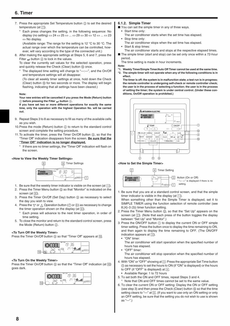
Operation No.Day Setting
<How to Set the Weekly Timer>1. Be sure that you are at a standard control screen, and that the weekly
timer indicator 1 is shown in the display.2. Press the Timer Menu button B, so that the “Set Up” appears on the
screen (at 2). (Note that each press of the button toggles the displaybetween “Set Up” and “Monitor”.)
3. Press the Timer On/Off (Set Day) button 9 to set the day. Each pressadvances the display at 3 to the next setting, in the following sequence:“Sun Mon Tues Wed Thurs Fri Sat” → “Sun” → ... → “Fri” → “Sat” → “SunMon Tues Wed Thurs Fri Sat”...
4. Press the or Operation button (7 or 8) as necessary to select theappropriate operation number (1 to 8) 4.* Your inputs at Steps 3 and 4 will select one of the cells from the matrix
illustrated below.(The remote-controller display at left shows how the display wouldappear when setting Operation 1 for Sunday to the values indicatedbelow.)
6. Timer
5. Operation
�
�
Low High
<To Change the Right/Left Air Direction>� Press the louver button 7 as necessary.
• The louver image 7 appears.Each press of the button switches the setting as follows.
(ON) (OFF)
During swing operation, the arrow dis-play move to the left and right.
No display(Stop)
5.6. VentillationsssssFor LOSSNAY combination5.6.1. For Wired Remote-controller� To run the ventilator together with the indoor unit:
� Press the ON/OFF button 1.• The Vent indication appears on the screen (at 8). The ventilator will
now automatically operate whenever the indoor unit is running.
5.6.2. For Wireless Remote-controller� The ventillator will automatically operate when the indoor unit turns on.� No indication on the wireless remote controller.
� To run the ventilator independently:� Press the Mode button 2 until appears on the display. This will
cause the ventilator to start.
� To change the ventilator force:� Press the Ventilation button 8 as necessary.
• Each press toggles the setting, as shown below.
Note:By setting the day to “Sun Mon Tues Wed Thurs Fri Sat”, you can set the sameoperation to be carried out at the same time every day.(Example: Operation 2 above, which is the same for all days of the week.)
<Setting the Weekly Timer>
Op No. Sunday Monday … Saturday
No. 1
No. 2
…
No. 8
• 8:30• ON• 23 °C
• 10:00• OFF
• 10:00• OFF
• 10:00• OFF
• 10:00• OFF
�
Setup Matrix
<Operation 1 settings for Sunday>
Start the air conditioner at 8:30, withthe temperature set to 23 °C.
�
<Operation 2 settings for every day>
Turn off the air conditioner at 10:00.
˚C
SUNON
WEEKLY
6
7
5 Shows the selected operation (ON or OFF)* Does not appear if operation is not set.
Shows the temperature setting* Does not appear if temperature is not
set.
Shows the timesetting
5. Press the appropriate Set Time button A as necessary to set thedesired time (at 5).* As you hold the button down, the time first increments in minute inter-
vals, then in ten-minute intervals, and then in one-hour intervals.6. Press the ON/OFF button 1 to select the desired operation (ON or
OFF), at 6.* Each press changes the next setting, in the following sequence:
No display (no setting) → “ON” → “OFF”
8
6.1.2. Simple Timer� You can set the simple timer in any of three ways.
• Start time only:The air conditioner starts when the set time has elapsed.
• Stop time only:The air conditioner stops when the set time has elapsed.
• Start & stop times:The air conditioner starts and stops at the respective elapsed times.
� The simple timer (start and stop) can be set only once within a 72-hourperiod.The time setting is made in hour increments.
Note:*1. Weekly Timer/Simple Timer/Auto Off Timer cannot be used at the same time.*2. The simple timer will not operate when any of the following conditions is in
effect.The timer is off; the system is in malfunction state; a test run is in progress;the remote controller is undergoing self-check or remote controller check;the user is in the process of selecting a function; the user is in the processof setting the timer; the system is under central control. (Under these con-ditions, On/Off operation is prohibited.)
ONHr
AFTER
SIMPLE
PAR-21MAA
ON/OFF
FILTER
CHECK
OPERATION CLEAR
TEST
TEMP.
MENU
BACK DAYMONITOR/SET
CLOCK
ON/OFF
2 A 9
0
4
1
B
ONHr
AFTER
SIMPLE
4
1
3
2 Timer Setting
Action (On or Off)* “— —” is displayed if there is no
setting.
<How to Set the Simple Timer>
1. Be sure that you are at a standard control screen, and that the simpletimer indicator is visible in the display (at 1).When something other than the Simple Timer is displayed, set it toSIMPLE TIMER using the function selection of remote controller (see8.[4]–3 (3)) timer function setting.
2. Press the Timer Menu button B, so that the “Set Up” appears on thescreen (at 2). (Note that each press of the button toggles the displaybetween “Set Up” and “Monitor”.)
3. Press the ON/OFF button 1 to display the current ON or OFF simpletimer setting. Press the button once to display the time remaining to ON,and then again to display the time remaining to OFF. (The ON/OFFindication appears at 3).• “ON” timer:
The air conditioner will start operation when the specified number ofhours has elapsed.
• “OFF” timer:The air conditioner will stop operation when the specified number ofhours has elapsed.
4. With “ON” or “OFF” showing at 3: Press the appropriate Set Time buttonA as necessary to set the hours to ON (if “ON” is displayed) or the hoursto OFF (if “OFF” is displayed) at 4.• Available Range: 1 to 72 hours
5. To set both the ON and OFF times, repeat Steps 3 and 4.* Note that ON and OFF times cannot be set to the same value.
6. To clear the current ON or OFF setting: Display the ON or OFF setting(see step 3) and then press the Check (Clear) button 0 so that the timesetting clears to “—” at 4. (If you want to use only an ON setting or onlyan OFF setting, be sure that the setting you do not wish to use is shownas “—”.)
Timer Settings
˚C
TIMERSUN
ON
OFF
WEEKLY 1
98
˚C
˚C
TIME SUN
WEEKLY
0
˚C
˚C
TIME SUN
WEEKLY
0
6. Timer
7. Press the appropriate Set Temperature button 3 to set the desiredtemperature (at 7).* Each press changes the setting, in the following sequence: No
display (no setting) ⇔ 24 ⇔ 25 ⇔ ... ⇔ 29 ⇔ 30 ⇔ 12 ⇔ ... ⇔ 23⇔ No display.(Available range: The range for the setting is 12 °C to 30 °C. Theactual range over which the temperature can be controlled, how-ever, will vary according to the type of the connected unit.)
8. After making the appropriate settings at Steps 5, 6 and 7, press theFilter button 4 to lock in the values.To clear the currently set values for the selected operation, pressand quickly release the Check (Clear) button 0 once.* The displayed time setting will change to “—:—”, and the On/Off
and temperature settings will all disappear.(To clear all weekly timer settings at once, hold down the Check(Clear) button 0 for two seconds or more. The display will beginflashing, indicating that all settings have been cleared.)
Note:Your new entries will be cancelled if you press the Mode (Return) button2 before pressing the Filter button 4.If you have set two or more different operations for exactly the sametime, only the operation with the highest Operation No. will be carriedout.
9. Repeat Steps 3 to 8 as necessary to fill as many of the available cellsas you wish.
10.Press the mode (Return) button 2 to return to the standard controlscreen and complete the setting procedure.
11.To activate the timer, press the Timer On/Off button 9, so that the“Timer Off” indication disappears from the screen. Be sure that the“Timer Off” indication is no longer displayed.* If there are no timer settings, the “Timer Off” indication will flash on
the screen.
<How to View the Weekly Timer Settings>
1. Be sure that the weekly timer indicator is visible on the screen (at 1).2. Press the Timer Menu button B so that “Monitor” is indicated on the
screen (at 8).3. Press the Timer On/Off (Set Day) button 9 as necessary to select
the day you wish to view.4. Press the or Operation button (7 or 8) as necessary to change
the timer operation shown on the display (at 9).* Each press will advance to the next timer operation, in order of
time setting.5. To close the monitor and return to the standard control screen, press
the Mode (Return) button 2.
<To Turn Off the Weekly Timer>Press the Timer On/Off button 9 so that “Timer Off” appears at 0.
<To Turn On the Weekly Timer>Press the Timer On/Off button 9 so that the “Timer Off” indication (at 0)goes dark.
9
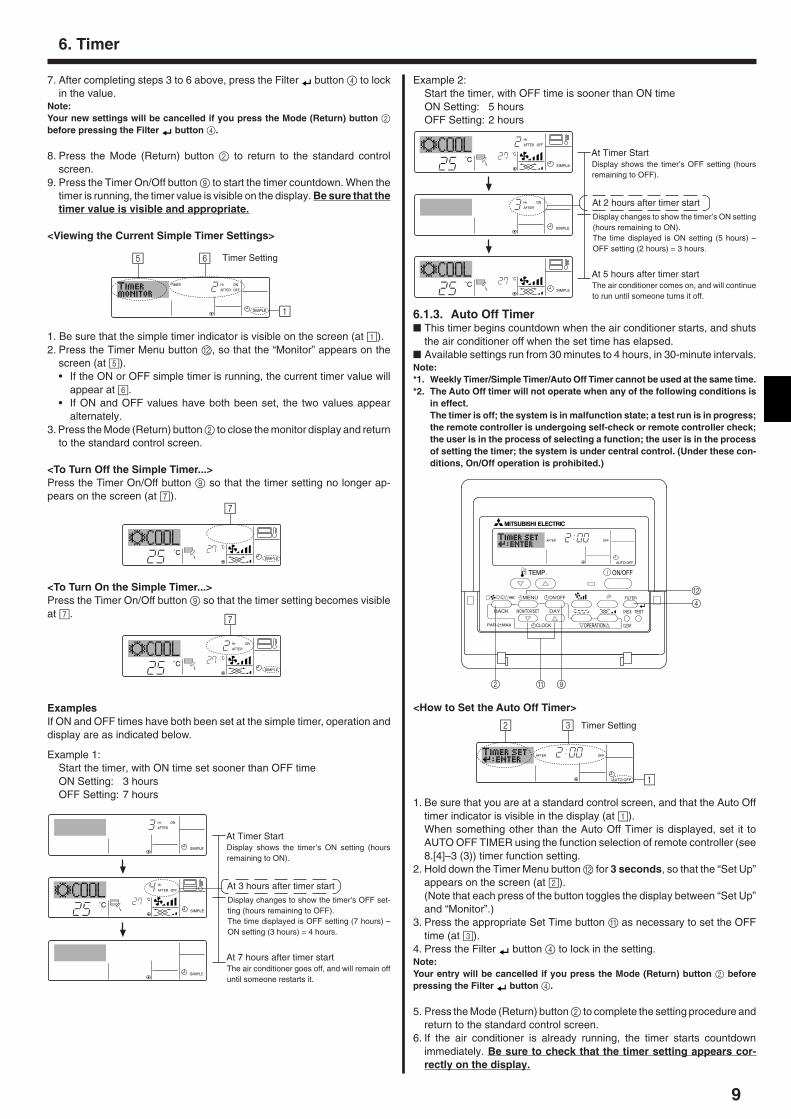
7. After completing steps 3 to 6 above, press the Filter button 4 to lockin the value.
Note:Your new settings will be cancelled if you press the Mode (Return) button 2before pressing the Filter button 4.
8. Press the Mode (Return) button 2 to return to the standard controlscreen.
9. Press the Timer On/Off button 9 to start the timer countdown. When thetimer is running, the timer value is visible on the display. Be sure that thetimer value is visible and appropriate.
<Viewing the Current Simple Timer Settings>
TIMER ON
OFF
Hr
AFTER
SIMPLE 1
65
1. Be sure that the simple timer indicator is visible on the screen (at 1).2. Press the Timer Menu button B, so that the “Monitor” appears on the
screen (at 5).• If the ON or OFF simple timer is running, the current timer value will
appear at 6.• If ON and OFF values have both been set, the two values appear
alternately.3. Press the Mode (Return) button 2 to close the monitor display and return
to the standard control screen.
<To Turn Off the Simple Timer...>Press the Timer On/Off button 9 so that the timer setting no longer ap-pears on the screen (at 7).
Timer Setting
˚C
˚CSIMPLE
7
˚C
˚C
ONHr
AFTER
SIMPLE
7
<To Turn On the Simple Timer...>Press the Timer On/Off button 9 so that the timer setting becomes visibleat 7.
ExamplesIf ON and OFF times have both been set at the simple timer, operation anddisplay are as indicated below.
Example 1:Start the timer, with ON time set sooner than OFF timeON Setting: 3 hoursOFF Setting: 7 hours
ONHr
AFTER
SIMPLE
˚C
˚C
OFF
Hr
AFTER
SIMPLE
SIMPLE
˚C
˚C
OFF
Hr
AFTER
SIMPLE
ONHr
AFTER
SIMPLE
�
�
�
At 3 hours after timer start
Display changes to show the timer’s OFF set-ting (hours remaining to OFF).The time displayed is OFF setting (7 hours) –ON setting (3 hours) = 4 hours.
At Timer StartDisplay shows the timer’s ON setting (hoursremaining to ON).
At 7 hours after timer startThe air conditioner goes off, and will remain offuntil someone restarts it.
˚C
˚CSIMPLE
�
At 2 hours after timer start
Display changes to show the timer’s ON setting(hours remaining to ON).The time displayed is ON setting (5 hours) –OFF setting (2 hours) = 3 hours.
At Timer StartDisplay shows the timer’s OFF setting (hoursremaining to OFF).
At 5 hours after timer startThe air conditioner comes on, and will continueto run until someone turns it off.
6.1.3. Auto Off Timer� This timer begins countdown when the air conditioner starts, and shuts
the air conditioner off when the set time has elapsed.� Available settings run from 30 minutes to 4 hours, in 30-minute intervals.Note:*1. Weekly Timer/Simple Timer/Auto Off Timer cannot be used at the same time.*2. The Auto Off timer will not operate when any of the following conditions is
in effect.The timer is off; the system is in malfunction state; a test run is in progress;the remote controller is undergoing self-check or remote controller check;the user is in the process of selecting a function; the user is in the processof setting the timer; the system is under central control. (Under these con-ditions, On/Off operation is prohibited.)
AFTER OFF
AUTO OFF
PAR-21MAA
ON/OFF
FILTER
CHECK
OPERATION CLEAR
TEST
TEMP.
MENU
BACK DAYMONITOR/SET
CLOCK
ON/OFF
2 A 9
4
B
AFTER OFF
AUTO OFF
3
1
2 Timer Setting
<How to Set the Auto Off Timer>
1. Be sure that you are at a standard control screen, and that the Auto Offtimer indicator is visible in the display (at 1).When something other than the Auto Off Timer is displayed, set it toAUTO OFF TIMER using the function selection of remote controller (see8.[4]–3 (3)) timer function setting.
2. Hold down the Timer Menu button B for 3 seconds, so that the “Set Up”appears on the screen (at 2).(Note that each press of the button toggles the display between “Set Up”and “Monitor”.)
3. Press the appropriate Set Time button A as necessary to set the OFFtime (at 3).
4. Press the Filter button 4 to lock in the setting.Note:Your entry will be cancelled if you press the Mode (Return) button 2 beforepressing the Filter button 4.
5. Press the Mode (Return) button 2 to complete the setting procedure andreturn to the standard control screen.
6. If the air conditioner is already running, the timer starts countdownimmediately. Be sure to check that the timer setting appears cor-rectly on the display.
Example 2:Start the timer, with OFF time is sooner than ON timeON Setting: 5 hoursOFF Setting: 2 hours
6. Timer
10
AFTER
TIMER
OFF
AUTO OFF
5
1
4 Timer Setting
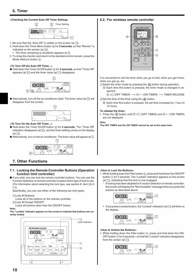
<Checking the Current Auto Off Timer Setting>
1. Be sure that the “Auto Off” is visible on the screen (at 1).2. Hold down the Timer Menu button B for 3 seconds, so that “Monitor” is
indicated on the screen (at 4).• The timer remaining to shutdown appears at 5.
3. To close the monitor and return to the standard control screen, press theMode (Return) button 2.
<To Turn Off the Auto Off Timer...>� Hold down the Timer On/Off button 9 for 3 seconds, so that “Timer Off”
appears (at 6) and the timer value (at 7) disappears.
� Alternatively, turn off the air conditioner itself. The timer value (at 7) willdisappear from the screen.
˚C
˚CAUTO OFF6
7
AUTO OFF
7
˚C
˚C
AFTER OFF
AUTO OFF6
7
<To Turn On the Auto Off Timer...>� Hold down the Timer On/Off button 9 for 3 seconds. The “Timer Off”
indication disappears (at 6), and the timer setting comes on the display(at 7).
� Alternatively, turn on the air conditioner. The timer value will appear at 7.
6.2. For wireless remote controller
It is convenient to set the timer when you go to bed, when you get home,when you get up, etc.1Select the timer mode by pressing the SELECT button during operation.
A Each time this button is pressed, the timer mode is changed in se-quence:
(OFF TIMER) (ON TIMER) TIMER RELEASE
2Set the time of the timer using the TIME button.
B Each time this button is pressed, the set time increases by 1 hour to12 hours.
To release the timer:• Press the
SELECT
button until (OFF TIMER) and (ON TIMER)are not displayed.
Note:The OFF TIMER and the ON TIMER cannot be set at the same time.
7. Other Functions
˚C
˚C
TIME SUN
FUNCTION
PAR-21MAA
ON/OFF
FILTER
CHECK
OPERATION CLEAR
TEST
TEMP.
MENU
BACK DAYMONITOR/SET
CLOCK
ON/OFF
4
1
1Lock Indicator
7.1. Locking the Remote Controller Buttons (Operationfunction limit controller)
� If you wish, you can lock the remote controller buttons. You can use theFunction Selection of remote controller to select which type of lock to use.(For information about selecting the lock type, see section 8, item [4]–2(1)).Specifically, you can use either of the following two lock types.
1Lock All Buttons:Locks all of the buttons on the remote controller.
2Lock All Except ON/OFF:Locks all buttons other than the ON/OFF button.
Note:The “Locked” indicator appears on the screen to indicate that buttons are cur-rently locked.
<How to Lock the Buttons>1. While holding down the Filter button 4, press and hold down the ON/OFF
button 1 for 2 seconds. The “Locked” indication appears on the screen(at 1), indicating that the lock is now engaged.* If locking has been disabled in Function Selection of remote controller,
the screen will display the “Not Available” message when you press thebuttons as described above.
• If you press a locked button, the “Locked” indication (at 1) will blink onthe display.
˚C
˚C
FUNCTION1
˚C
˚C
FUNCTION1
˚C
˚C
1
<How to Unlock the Buttons>1. While holding down the Filter button 4, press and hold down the ON/
OFF button 1 for 2 seconds—so that the “Locked” indication disappearsfrom the screen (at 1).
6. Timer
ON/OFF
RESET
TOOWARM
TOOCOOL
MODE
AUTO COOL
DRYHEAT
FAN
VANE
SELECT
TIME
h
1
BA
2
11
ON/OFF TEMP.
˚C
˚C
ON/OFF TEMP.
˚C
˚C
ON/OFF
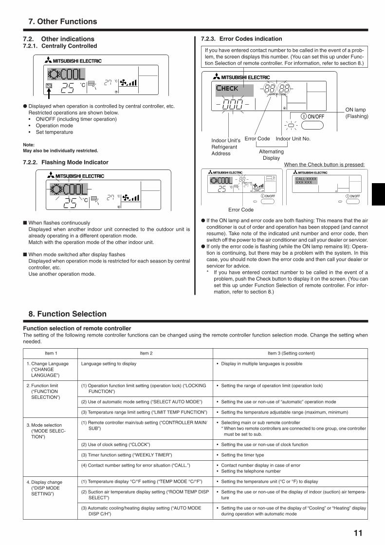
ERROR CODE
If you have entered contact number to be called in the event of a prob-lem, the screen displays this number. (You can set this up under Func-tion Selection of remote controller. For information, refer to section 8.)
7. Other Functions
7.2. Other indications7.2.1. Centrally Controlled
� When flashes continuouslyDisplayed when another indoor unit connected to the outdoor unit isalready operating in a different operation mode.Match with the operation mode of the other indoor unit.
� When mode switched after display flashesDisplayed when operation mode is restricted for each season by centralcontroller, etc.Use another operation mode.
� Displayed when operation is controlled by central controller, etc.Restricted operations are shown below.• ON/OFF (including timer operation)• Operation mode• Set temperature
Note:May also be individually restricted.
7.2.2. Flashing Mode Indicator
Indoor Unit’sRefrigerantAddress
Error Code Indoor Unit No.
AlternatingDisplay
ON/OFF
˚C
˚C
ERROR CODE
ON/OFF
CALL:XXXXXXX:XXX
Error Code
When the Check button is pressed:
ON lamp(Flashing)
7.2.3. Error Codes indication
� If the ON lamp and error code are both flashing: This means that the airconditioner is out of order and operation has been stopped (and cannotresume). Take note of the indicated unit number and error code, thenswitch off the power to the air conditioner and call your dealer or servicer.
� If only the error code is flashing (while the ON lamp remains lit): Opera-tion is continuing, but there may be a problem with the system. In thiscase, you should note down the error code and then call your dealer orservicer for advice.* If you have entered contact number to be called in the event of a
problem, push the Check button to display it on the screen. (You canset this up under Function Selection of remote controller. For infor-mation, refer to section 8.)
8. Function Selection
Function selection of remote controllerThe setting of the following remote controller functions can be changed using the remote controller function selection mode. Change the setting whenneeded.
Item 1
1. Change Language(“CHANGELANGUAGE”)
2. Function limit(“FUNCTIONSELECTION”)
3. Mode selection(“MODE SELEC-TION”)
4. Display change(“DISP MODESETTING”)
Item 2
Language setting to display
(1) Operation function limit setting (operation lock) (“LOCKINGFUNCTION”)
(2) Use of automatic mode setting (“SELECT AUTO MODE”)
(3) Temperature range limit setting (“LIMIT TEMP FUNCTION”)
(1) Remote controller main/sub setting (“CONTROLLER MAIN/SUB”)
(2) Use of clock setting (“CLOCK”)
(3) Timer function setting (“WEEKLY TIMER”)
(4) Contact number setting for error situation (“CALL.”)
(1) Temperature display °C/°F setting (“TEMP MODE °C/°F”)
(2) Suction air temperature display setting (“ROOM TEMP DISPSELECT”)
(3) Automatic cooling/heating display setting (“AUTO MODEDISP C/H”)
Item 3 (Setting content)
• Display in multiple languages is possible
• Setting the range of operation limit (operation lock)
• Setting the use or non-use of “automatic” operation mode
• Setting the temperature adjustable range (maximum, minimum)
• Selecting main or sub remote controller* When two remote controllers are connected to one group, one controller
must be set to sub.
• Setting the use or non-use of clock function
• Setting the timer type
• Contact number display in case of error• Setting the telephone number
• Setting the temperature unit (°C or °F) to display
• Setting the use or non-use of the display of indoor (suction) air tempera-ture
• Setting the use or non-use of the display of “Cooling” or “Heating” displayduring operation with automatic mode
12
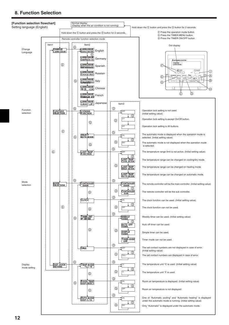
[Function selection flowchart]Setting language (English)
OFF
on1
on2
OFF
ON
OFF
ON
OFF
OFF
CALL-
ON
OFF
ON
OFF
°C
°F
PAR-21MAA
ON/OFF
FILTER
CHECK
OPERATION CLEAR
TEST
TEMP.
MENU
BACK DAYMONITOR/SET
CLOCK
ON/OFF
F
E
G
C D
H
B
A
I
G
G
G
G
G
G
E
E
G
G
G
G
G
E
G
E
G
G
G
G
D
D
D
D
D
D
D
D
D
D
D
D
D
D
D
D
D
D
D
D
D
D
D
D
D
D
D
D
D
D
English
Germany
Spanish
Russian
Italy
Chinese
French
Japanese
Hold down the E button and press the D button for 2 seconds.
Hold down the E button and press the D button for 2 seconds.
Remote controller function selection mode
E Press the operation mode button.G Press the TIMER MENU button.D Press the TIMER ON/OFF button.
Item1 Item2 Dot display
Item3
Room air temperature is not displayed.
One of “Automatic cooling” and “Automatic heating” is displayedunder the automatic mode is running. (Initial setting value)
Only “Automatic” is displayed under the automatic mode.
Normal display(Display when the air condition is not running)
ChangeLanguage
Functionselection
Modeselection
Displaymode setting
8. Function Selection
Operation lock setting is not used.(Initial setting value)
Operation lock setting is except On/Off button.
Operation lock setting is All buttons.
The automatic mode is displayed when the operation mode isselected. (Initial setting value)
The automatic mode is not displayed when the operation mode is selected.
The temperature range limit is not active. (Initial setting value)
The temperature range can be changed on cooling/dry mode.
The temperature range can be changed on heating mode.
The temperature range can be changed on automatic mode.
The remote controller will be the main controller. (Initial setting value)
The remote controller will be the sub controller.
The clock function can be used. (Initial setting value)
The clock function can not be used.
Weekly timer can be used. (Initial setting value)
Auto off timer can be used.
Simple timer can be used.
Timer mode can not be used.
The set contact numbers are not displayed in case of error.(Initial setting value)
The set contact numbers are displayed in case of error.
The temperature unit °C is used. (Initial setting value)
The temperature unit °F is used.
Room air temperature is displayed. (Initial setting value)
13
[Detailed setting]
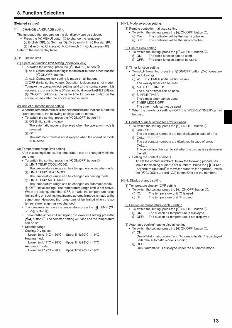
[4]–1. CHANGE LANGUAGE setting
The language that appears on the dot display can be selected.• Press the [ MENU] button G to change the language.
1 English (GB), 2 German (D), 3 Spanish (E), 4 Russian (RU),5 Italian (I), 6 Chinese (CH), 7 French (F), 8 Japanese (JP)
Refer to the dot display table.
[4]–2. Function limit
(1) Operation function limit setting (operation lock)• To switch the setting, press the [ ON/OFF] button D.
1 no1: Operation lock setting is made on all buttons other than the[ ON/OFF] button.
2 no2: Operation lock setting is made on all buttons.3 OFF (Initial setting value): Operation lock setting is not made.
* To make the operation lock setting valid on the normal screen, it isnecessary to press buttons (Press and hold down the [FILTER] and[ ON/OFF] buttons at the same time for two seconds.) on thenormal screen after the above setting is made.
(2) Use of automatic mode settingWhen the remote controller is connected to the unit that has automaticoperation mode, the following settings can be made.• To switch the setting, press the [ ON/OFF] button D.
1 ON (Initial setting value):The automatic mode is displayed when the operation mode isselected.
2 OFF:The automatic mode is not displayed when the operation modeis selected.
(3) Temperature range limit settingAfter this setting is made, the temperature can be changed within theset range.• To switch the setting, press the [ ON/OFF] button D.
1 LIMIT TEMP COOL MODE:The temperature range can be changed on cooling/dry mode.
2 LIMIT TEMP HEAT MODE:The temperature range can be changed on heating mode.
3 LIMIT TEMP AUTO MODE:The temperature range can be changed on automatic mode.
4 OFF (initial setting): The temperature range limit is not active.* When the setting, other than OFF, is made, the temperature range
limit setting on cooling, heating and automatic mode is made at thesame time. However, the range cannot be limited when the settemperature range has not changed.
• To increase or decrease the temperature, press the [ TEMP. ( )or ( )] button F.
• To switch the upper limit setting and the lower limit setting, press the[ ] button H. The selected setting will flash and the temperaturecan be set.
• Settable rangeCooling/Dry mode:
Lower limit:19°C ~ 30°C Upper limit:30°C ~ 19°CHeating mode:
Lower limit:17°C ~ 28°C Upper limit:28°C ~ 17°CAutomatic mode:
Lower limit:19°C ~ 28°C Upper limit:28°C ~ 19°C
[4]–3. Mode selection setting
(1) Remote controller main/sub setting• To switch the setting, press the [ ON/OFF] button D.
1 Main: The controller will be the main controller.2 Sub: The controller will be the sub controller.
(2) Use of clock setting• To switch the setting, press the [ ON/OFF] button D.
1 ON: The clock function can be used.2 OFF: The clock function cannot be used.
(3) Timer function setting• To switch the setting, press the [ ON/OFF] button D (Choose one
of the followings.).1 WEEKLY TIMER (initial setting value):
The weekly timer can be used.2 AUTO OFF TIMER:
The auto off timer can be used.3 SIMPLE TIMER:
The simple timer can be used.4 TIMER MODE OFF:
The timer mode cannot be used.* When the use of clock setting is OFF, the “WEEKLY TIMER” cannot
be used.
(4) Contact number setting for error situation• To switch the setting, press the [ ON/OFF] button D.
1 CALL OFF:The set contact numbers are not displayed in case of error.
2 CALL **** *** ****:The set contact numbers are displayed in case of error.CALL_:The contact number can be set when the display is as shown onthe left.
• Setting the contact numbersTo set the contact numbers, follow the following procedures.Move the flashing cursor to set numbers. Press the [ TEMP.( ) and ( )] button F to move the cursor to the right (left). Pressthe [ CLOCK ( ) and ( )] button C to set the numbers.
[4]–4. Display change setting
(1) Temperature display °C/°F setting• To switch the setting, press the [ ON/OFF] button D.
1 °C: The temperature unit °C is used.2 °F: The temperature unit °F is used.
(2) Suction air temperature display setting• To switch the setting, press the [ ON/OFF] button D.
1 ON: The suction air temperature is displayed.2 OFF: The suction air temperature is not displayed.
(3) Automatic cooling/heating display setting• To switch the setting, press the [ ON/OFF] button D.
1 ON:One of “Automatic cooling” and “Automatic heating” is displayedunder the automatic mode is running.
2 OFF:Only “Automatic” is displayed under the automatic mode.
8. Function Selection
14
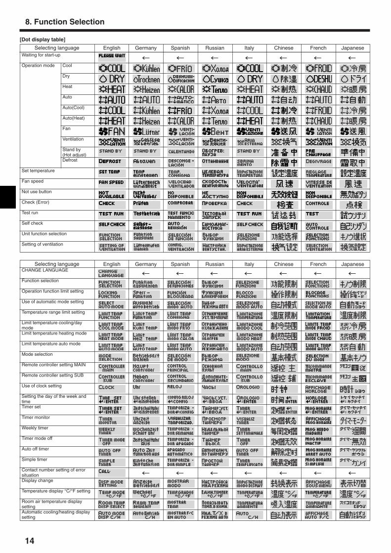
[Dot display table]
8. Function Selection
Waiting for start-up
Operation mode Cool
Dry
Heat
Auto
Auto(Cool)
Auto(Heat)
Fan
Ventilation
Stand by(Hot adjust)Defrost
Set temperature
Fan speed
Not use button
Check (Error)
Test run
Self check
Unit function selection
Setting of ventilation
CHANGE LANGUAGE
Function selection
Operation function limit setting
Use of automatic mode setting
Temperature range limit setting
Limit temperature cooling/daymodeLimit temperature heating mode
Limit temperature auto mode
Mode selection
Remote controller setting MAIN
Remote controller setting SUB
Use of clock setting
Setting the day of the week andtimeTimer set
Timer monitor
Weekly timer
Timer mode off
Auto off timer
Simple timer
Contact number setting of errorsituationDisplay change
Temperature display °C/°F setting
Room air temperature displaysettingAutomatic cooling/heating displaysetting
Selecting language
Selecting language English Germany Spanish Russian Italy Chinese French Japanese
English Germany Spanish Russian Italy Chinese French Japanese
15
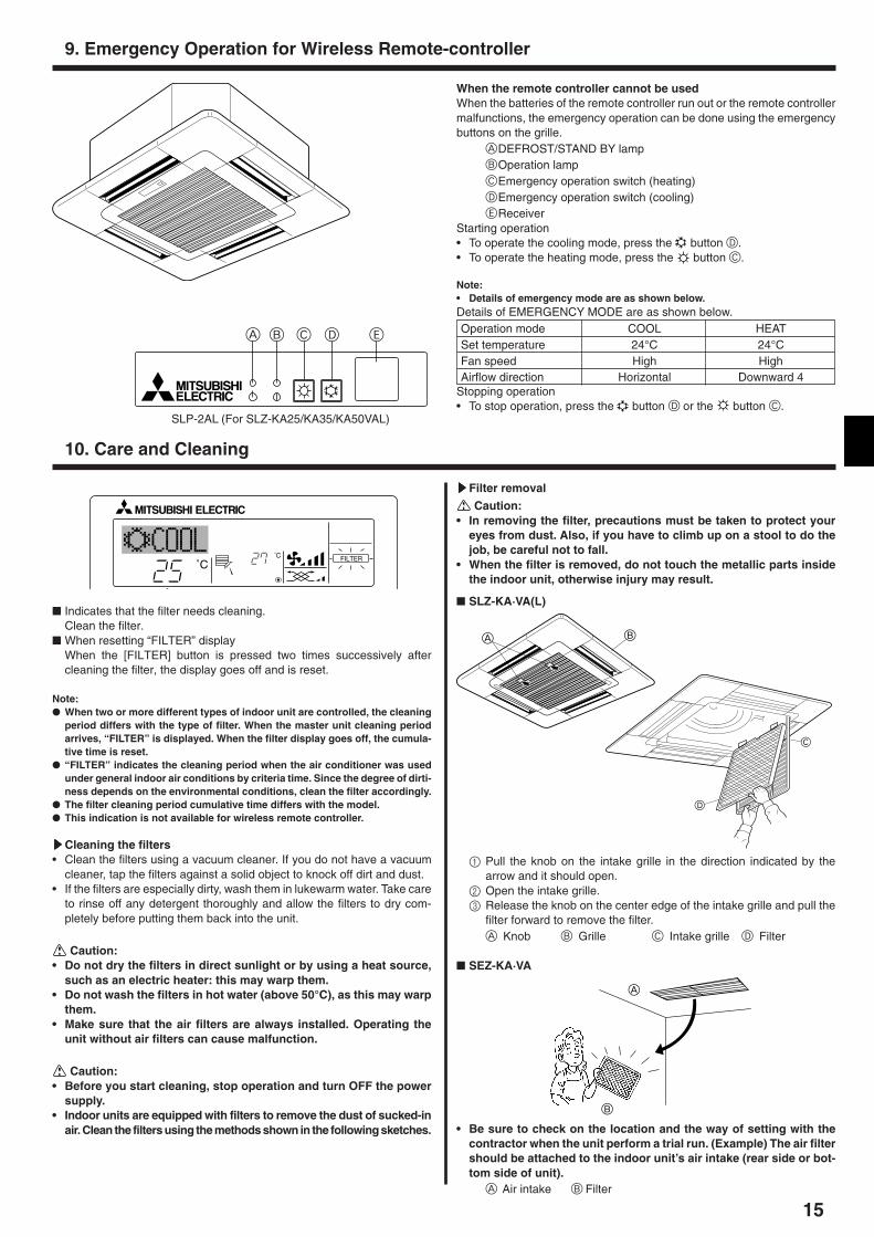
When the remote controller cannot be usedWhen the batteries of the remote controller run out or the remote controllermalfunctions, the emergency operation can be done using the emergencybuttons on the grille.
ADEFROST/STAND BY lampBOperation lampCEmergency operation switch (heating)DEmergency operation switch (cooling)EReceiver
Starting operation• To operate the cooling mode, press the button D.• To operate the heating mode, press the button C.
Note:• Details of emergency mode are as shown below.Details of EMERGENCY MODE are as shown below.Operation mode COOL HEATSet temperature 24°C 24°CFan speed High HighAirflow direction Horizontal Downward 4
Stopping operation• To stop operation, press the button D or the button C.
9. Emergency Operation for Wireless Remote-controller
ON/OFF TEMP.
˚C
˚CFILTER
� Indicates that the filter needs cleaning.Clean the filter.
� When resetting “FILTER” displayWhen the [FILTER] button is pressed two times successively aftercleaning the filter, the display goes off and is reset.
Note:� When two or more different types of indoor unit are controlled, the cleaning
period differs with the type of filter. When the master unit cleaning periodarrives, “FILTER” is displayed. When the filter display goes off, the cumula-tive time is reset.
� “FILTER” indicates the cleaning period when the air conditioner was usedunder general indoor air conditions by criteria time. Since the degree of dirti-ness depends on the environmental conditions, clean the filter accordingly.
� The filter cleaning period cumulative time differs with the model.� This indication is not available for wireless remote controller.
sssssCleaning the filters• Clean the filters using a vacuum cleaner. If you do not have a vacuum
cleaner, tap the filters against a solid object to knock off dirt and dust.• If the filters are especially dirty, wash them in lukewarm water. Take care
to rinse off any detergent thoroughly and allow the filters to dry com-pletely before putting them back into the unit.
Caution:• Do not dry the filters in direct sunlight or by using a heat source,
such as an electric heater: this may warp them.• Do not wash the filters in hot water (above 50°C), as this may warp
them.• Make sure that the air filters are always installed. Operating the
unit without air filters can cause malfunction.
Caution:• Before you start cleaning, stop operation and turn OFF the power
supply.• Indoor units are equipped with filters to remove the dust of sucked-in
air. Clean the filters using the methods shown in the following sketches.
10. Care and Cleaning
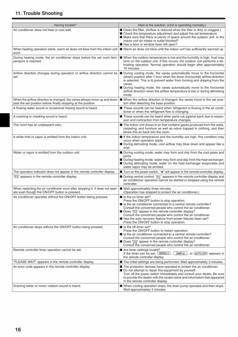
sssssFilter removal
Caution:• In removing the filter, precautions must be taken to protect your
eyes from dust. Also, if you have to climb up on a stool to do thejob, be careful not to fall.
• When the filter is removed, do not touch the metallic parts insidethe indoor unit, otherwise injury may result.
� SLZ-KA·VA(L)
BA
D
C
1 Pull the knob on the intake grille in the direction indicated by thearrow and it should open.
2 Open the intake grille.3 Release the knob on the center edge of the intake grille and pull the
filter forward to remove the filter.A Knob B Grille C Intake grille D Filter
� SEZ-KA·VA
A B C D E
SLP-2AL (For SLZ-KA25/KA35/KA50VAL)
• Be sure to check on the location and the way of setting with thecontractor when the unit perform a trial run. (Example) The air filtershould be attached to the indoor unit’s air intake (rear side or bot-tom side of unit).
A Air intake B Filter
A
B
16
Having trouble?
Air conditioner does not heat or cool well.
When heating operation starts, warm air does not blow from the indoor unitsoon.
During heating mode, the air conditioner stops before the set room tem-perature is reached.
Airflow direction changes during operation or airflow direction cannot beset.
When the airflow direction is changed, the vanes always move up and downpast the set position before finally stopping at the position.
A flowing water sound or occasional hissing sound is heard.
A cracking or creaking sound is heard.
The room has an unpleasant odor.
A white mist or vapor is emitted from the indoor unit.
Water or vapor is emitted from the outdoor unit.
The operation indicator does not appear in the remote controller display.
“ ” appears in the remote controller display.
When restarting the air conditioner soon after stopping it, it does not oper-ate even though the ON/OFF button is pressed.
Air conditioner operates without the ON/OFF button being pressed.
Air conditioner stops without the ON/OFF button being pressed.
Remote controller timer operation cannot be set.
“PLEASE WAIT” appears in the remote controller display.
An error code appears in the remote controller display.
Draining water or motor rotation sound is heard.
Here is the solution. (Unit is operating normally.)
� Clean the filter. (Airflow is reduced when the filter is dirty or clogged.)� Check the temperature adjustment and adjust the set temperature.� Make sure that there is plenty of space around the outdoor unit. Is the
indoor unit air intake or outlet blocked?� Has a door or window been left open?
� Warm air does not blow until the indoor unit has sufficiently warmed up.
� When the outdoor temperature is low and the humidity is high, frost mayform on the outdoor unit. If this occurs, the outdoor unit performs a de-frosting operation. Normal operation should begin after approximately10 minutes.
� During cooling mode, the vanes automatically move to the horizontal(down) position after 1 hour when the down (horizontal) airflow directionis selected. This is to prevent water from forming and dripping from thevanes.
� During heating mode, the vanes automatically move to the horizontalairflow direction when the airflow temperature is low or during defrostingmode.
� When the airflow direction is changed, the vanes move to the set posi-tion after detecting the base position.
� These sounds can be heard when refrigerant is flowing in the air condi-tioner or when the refrigerant flow is changing.
� These sounds can be heard when parts rub against each due to expan-sion and contraction from temperature changes.
� The indoor unit draws in air that contains gases produced from the walls,carpeting, and furniture as well as odors trapped in clothing, and thenblows this air back into the room.
� If the indoor temperature and the humidity are high, this condition mayoccur when operation starts.
� During defrosting mode, cool airflow may blow down and appear like amist.
� During cooling mode, water may form and drip from the cool pipes andjoints.
� During heating mode, water may form and drip from the heat exchanger.� During defrosting mode, water on the heat exchanger evaporates and
water vapor may be emitted.
� Turn on the power switch. “ ” will appear in the remote controller display.
� During central control, “ ” appears in the remote controller display andair conditioner operation cannot be started or stopped using the remotecontroller.
� Wait approximately three minutes.(Operation has stopped to protect the air conditioner.)
� Is the on timer set?Press the ON/OFF button to stop operation.
� Is the air conditioner connected to a central remote controller?Consult the concerned people who control the air conditioner.
� Does “ ” appear in the remote controller display?Consult the concerned people who control the air conditioner.
� Has the auto recovery feature from power failures been set?Press the ON/OFF button to stop operation.
� Is the off timer set?Press the ON/OFF button to restart operation.
� Is the air conditioner connected to a central remote controller?Consult the concerned people who control the air conditioner.
� Does “ ” appear in the remote controller display?Consult the concerned people who control the air conditioner.
� Are timer settings invalid?If the timer can be set, WEEKLY , SIMPLE , or AUTO OFF appears inthe remote controller display.
� The initial settings are being performed. Wait approximately 3 minutes.
� The protection devices have operated to protect the air conditioner.� Do not attempt to repair this equipment by yourself.
Turn off the power switch immediately and consult your dealer. Be sureto provide the dealer with the model name and information that appearedin the remote controller display.
� When cooling operation stops, the drain pump operates and then stops.Wait approximately 3 minutes.
11. Trouble Shooting
17
Having trouble? Here is the solution. (Unit is operating normally.)
Noise is louder than specifications.
Nothing appears in the wireless remote controller display, the display isfaint, or signals are not received by the indoor unit unless the remote con-troller is close.
The operation lamp near the receiver for the wireless remote controller onthe indoor unit is flashing.
� The indoor operation sound level is affected by the acoustics of the par-ticular room as shown in the following table and will be higher than thenoise specification, which was measured in an echo-free room.
� The batteries are low.Replace the batteries and press the Reset button.
� If nothing appears even after the batteries are replaced, make sure thatthe batteries are installed in the correct directions (+, –).
� The self diagnosis function has operated to protect the air conditioner.� Do not attempt to repair this equipment by yourself.
Turn off the power switch immediately and consult your dealer. Be sureto provide the dealer with the model name.
High sound-absorbing rooms
Broadcastingstudio, music
room, etc.
3 to 7 dB
Normal rooms
Reception room,hotel lobby, etc.
6 to 10 dB
Low sound-absorbing rooms
Office, hotelroom
9 to 13 dB
Locationexamples
Noise levels
11. Trouble Shooting
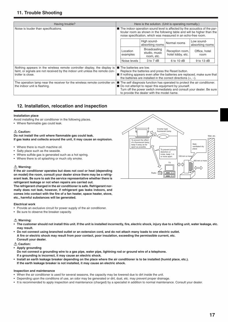
Installation placeAvoid installing the air conditioner in the following places.• Where flammable gas could leak.
Caution:Do not install the unit where flammable gas could leak.If gas leaks and collects around the unit, it may cause an explosion.
• Where there is much machine oil.• Salty place such as the seaside.• Where sulfide gas is generated such as a hot spring.• Where there is oil splashing or much oily smoke.
Warning:If the air conditioner operates but does not cool or heat (dependingon model) the room, consult your dealer since there may be a refrig-erant leak. Be sure to ask the service representative whether there isrefrigerant leakage or not when repairs are carried out.The refrigerant charged in the air conditioner is safe. Refrigerant nor-mally does not leak, however, if refrigerant gas leaks indoors, andcomes into contact with the fire of a fan heater, space heater, stove,etc., harmful substances will be generated.
Inverter typefluorescent lamp
To prevent the effectof a fluorescent lamp,keep it away as farapart as possible.
To prevent picturedistortion ornoise, keep 1 mor more apart.
TV
Radio
100 mm or more
400 mm or more
Well-ventilated dryplace
Wall, etc.
12. Installation, relocation and inspection
Electrical work• Provide an exclusive circuit for power supply of the air conditioner.• Be sure to observe the breaker capacity.
Warning:• The customer should not install this unit. If the unit is installed incorrectly, fire, electric shock, injury due to a falling unit, water leakage, etc.
may result.• Do not connect using branched outlet or an extension cord, and do not attach many loads to one electric outlet.
A fire or electric shock may result from poor contact, poor insulation, exceeding the permissible current, etc.Consult your dealer.
Caution:• Apply grounding
Do not connect a grounding wire to a gas pipe, water pipe, lightning rod or ground wire of a telephone.If a grounding is incorrect, it may cause an electric shock.
• Install an earth leakage breaker depending on the place where the air conditioner is to be installed (humid place, etc.).If the earth leakage breaker is not installed, it may cause an electric shock.
Inspection and maintenance• When the air conditioner is used for several seasons, the capacity may be lowered due to dirt inside the unit.• Depending upon the conditions of use, an odor may be generated or dirt, dust, etc. may prevent proper drainage.• It is recommended to apply inspection and maintenance (charged) by a specialist in addition to normal maintenance. Consult your dealer.
Please be sure to put the contact address/telephone number onthis manual before handing it to the customer.
• Low Voltage Directive 73/23/ EEC• Electromagnetic Compatibility Directive 89/
336/ EEC
This product is designed and intended for use in the residential,commercial and light-industrial environment.
HEAD OFFICE: MITSUBISHI DENKI BLDG., 2-2-3, MARUNOUCHI, CHIYODA-KU, TOKYO 100-8310, JAPAN
Printed in ThailandBG79U786H01
The product at hand isbased on the followingEU regulations: