Embed Size (px)
Citation preview

1. Fachinformation
Der AL66 mit Veränderbar ccTalk ist erhältlich als: V = Einwurf von oben, akzeptierte Münz von unten vorn, abgelehnt Münze von unten hinten I = Einwurf von oben, akzeptierte Münz von unten hinten, abgelehnt Münze von unten vorn K = Einwurf von vorn/oben, akzeptierte Münz von unten hinten, abgelehnt Münze vorn S = Einwurf von vorn, akzeptierte Münz von unten hinten, abgelehnt Münze vorn
Technische Datei
Mechanische Daten Einbaumaße 3½” standard Höhe x Breite x Tiefe 88 x 102 x 52 mm Gewicht 200 g
Electrische Daten Betriebsspannung: 8 V DC - 26 V DC Akzeptierungs Nennstrom: 350 mA(30 ms)/100 mA Messungs Nennstrom: ≤25 mA Stand by Mode ≤20 mA Standard Energiesparen ≤2,5 mA Auto-Weck ≤3,5 mA Ausgang Open collector
Sättigungs Ausgang Spannung ≤1 V Ausgang Spannung max. 50 V Ausgang Strom max. 250 mA Eingang Auslösung Spannung min. 3 V Eingang Spannung max 50 V Eingang Impedanz ≈55 kΩ
Annahme: 16 gleichzeitig aktive Kanäle für max. 15 verschiedene Münzen Durchmesser min. 16 mm Durchmesser max. 32 mm Dicke 1 to 3,4 mm
Zeit Daten Wiederherstellung nach Einschaltung ≤200 ms Wiederherstellung nach Auto-Weck ≤50 ms
Raumlage Temperaturbereich 0°C - 60°C Lager Temperatur minus 30°C - 70°C Feuchte bis 75% (nichtkondensierend) standard bis 95% tropenfest version
EMC Diese Produkt ist mit EN55014-1 und EN55014-2 verträglich
> 8-bit Microprozessor mit 36 KB Flash-funktion, geschütz gegen magnetisch Interferenz und extreme Raumlage. > Meßwerte aus Sechs Induktiv Sensoren und ein optisches Detektor vereinigen zu geben die hoheste Genauigkeit der Unterscheidung. > Mechanisches Schutz gegen Manipulation. Optisches Sensoren sind so gelegen, die kein Schwindel auftreten kann.
AL&& ccTalk Münzprüfer
Gebrauchsanweisung
Rev. 1.00
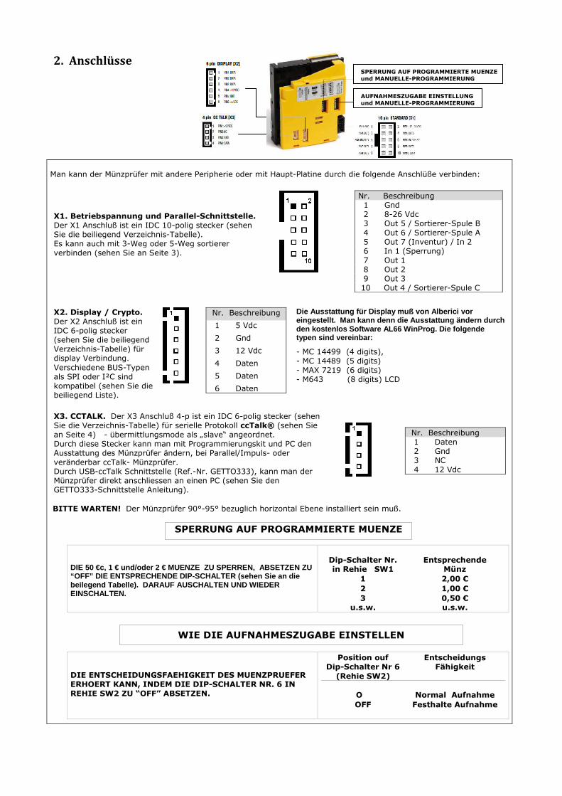
2. Anschlüsse
Man kann der Münzprüfer mit andere Peripherie oder mit Haupt-Platine durch die folgende Anschlüße verbinden:
X1. Betriebspannung und Parallel-Schnittstelle. Der X1 Anschluß ist ein IDC 10-polig stecker (sehen Sie die beiliegend Verzeichnis-Tabelle). Es kann auch mit 3-Weg oder 5-Weg sortierer verbinden (sehen Sie an Seite 3).
Nr. Beschreibung 1 Gnd 2 8-26 Vdc 3 Out 5 / Sortierer-Spule B 4 Out 6 / Sortierer-Spule A 5 Out 7 (Inventur) / In 2 6 In 1 (Sperrung) 7 Out 1 8 Out 2 9 Out 3 10 Out 4 / Sortierer-Spule C
X2. Display / Crypto. Der X2 Anschluß ist ein IDC 6-polig stecker (sehen Sie die beiliegend Verzeichnis-Tabelle) für display Verbindung.
Verschiedene BUS-Typen als SPI oder I²C sind kompatibel (sehen Sie die beiliegend Liste).
Nr. Beschreibung
1 5 Vdc
2 Gnd
3 12 Vdc
4 Daten
5 Daten
6 Daten
Die Ausstattung für Display muß von Alberici v or eingestellt. Man kann denn die Ausstattung ändern durch den kostenlos Software AL66 WinProg. Die folgende typen sind vereinbar:
- MC 14499 (4 digits), - MC 14489 (5 digits) - MAX 7219 (6 digits) - M643 (8 digits) LCD
X3. CCTALK. Der X3 Anschluß 4-p ist ein IDC 6-polig stecker (sehen Sie die Verzeichnis-Tabelle) für serielle Protokoll ccTalk® (sehen Sie an Seite 4) - übermittlungsmode als „slave“ angeordnet. Durch diese Stecker kann man mit Programmierungskit und PC den Ausstattung des Münzprüfer ändern, bei Parallel/Impuls- oder veränderbar ccTalk- Münzprüfer. Durch USB-ccTalk Schnittstelle (Ref.-Nr. GETTO333), kann man der Münzprüfer direkt anschliessen an einen PC (sehen Sie den GETTO333-Schnittstelle Anleitung).
Nr. Beschreibung 1 Daten 2 Gnd 3 NC 4 12 Vdc
BITTE WARTEN! Der Münzprüfer 90°-95° bezuglich horizontal Ebene installiert sein muß.
DIE 50 €c, 1 € und/oder 2 € MUENZE ZU SPERREN, AB SETZEN ZU “OFF” DIE ENTSPRECHENDE DIP-SCHALTER (sehen Sie an die beilegend Tabelle). DARAUF AUSCHALTEN UND WIEDER EINSCHALTEN.
Dip-Schalter Nr. in Rehie SW1
Entsprechende Münz
1 2,00 €
2 1,00 €
3 u.s.w.
0,50 € u.s.w.
DIE ENTSCHEIDUNGSFAEHIGKEIT DES MUENZPRUEFER ERHOERT KANN, INDEM DIE DIP-SCHALTER NR. 6 IN REHIE SW2 ZU “OFF” ABSETZEN.
Position ouf Dip-Schalter Nr 6
(Rehie SW2)
Entscheidungs Fähigkeit
O
Normal Aufnahme
OFF Festhalte Aufnahme
WIE DIE AUFNAHMESZUGABE EINSTELLEN
SPERRUNG AUF PROGRAMMIERTE MUENZE
SPERRUNG AUF PROGRAMMIERTE MUENZE
und MANUELLE-PROGRAMMIERUNG
AUFNAHMESZUGABE EINSTELLUNG
und MANUELLE-PROGRAMMIERUNG

AL66V + “C” -Gehäuse + Variant Sortierer
Verschiedene Kombinationen mit AL66V
AL66S + “S”-Frontplatte
3. Abmessungen
“S” FRONTPLATTE FUER AL66S
“K” FRONTPLATTE FUER AL66S
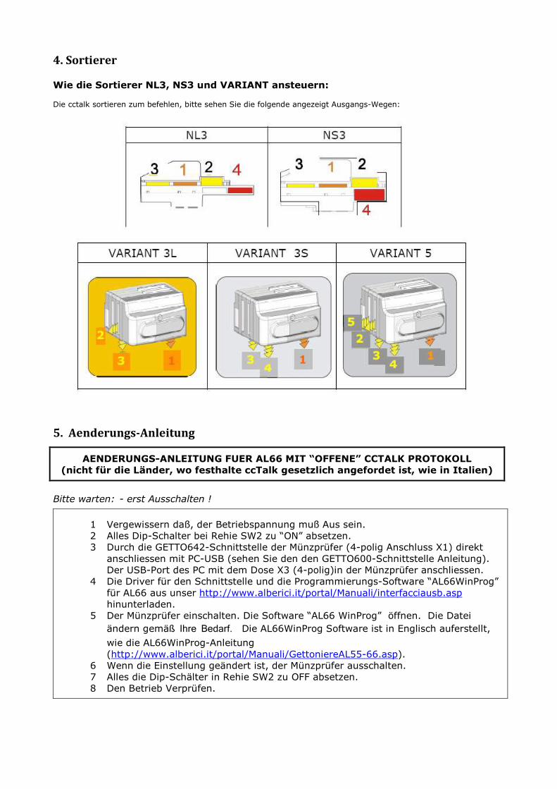
4. Sortierer
Wie die Sortierer NL3, NS3 und VARIANT ansteuern: Die cctalk sortieren zum befehlen, bitte sehen Sie die folgende angezeigt Ausgangs-Wegen:
5. Aenderungs-Anleitung
AENDERUNGS-ANLEITUNG FUER AL66 MIT “OFFENE” CCTALK PROTOKOLL
(nicht für die Länder, wo festhalte ccTalk gesetzlich angefordet ist, wie in Italien)
Bitte warten: - erst Ausschalten !
1 Vergewissern daß, der Betriebspannung muß Aus sein.
2 Alles Dip-Schalter bei Rehie SW2 zu “ON” absetzen.
3 Durch die GETTO642-Schnittstelle der Münzprüfer (4-polig Anschluss X1) direkt
anschliessen mit PC-USB (sehen Sie den den GETTO600-Schnittstelle Anleitung).
Der USB-Port des PC mit dem Dose X3 (4-polig)in der Münzprüfer anschliessen.
4 Die Driver für den Schnittstelle und die Programmierungs-Software “AL66WinProg”
für AL66 aus unser http://www.alberici.it/portal/Manuali/interfacciausb.asp
hinunterladen.
5 Der Münzprüfer einschalten. Die Software “AL66 WinProg” öffnen. Die Datei
ändern gemäß Ihre Bedarf. Die AL66WinProg Software ist in Englisch auferstellt,
wie die AL66WinProg-Anleitung
(http://www.alberici.it/portal/Manuali/GettoniereAL55-66.asp).
6 Wenn die Einstellung geändert ist, der Münzprüfer ausschalten.
7 Alles die Dip-Schälter in Rehie SW2 zu OFF absetzen.
8 Den Betrieb Verprüfen.
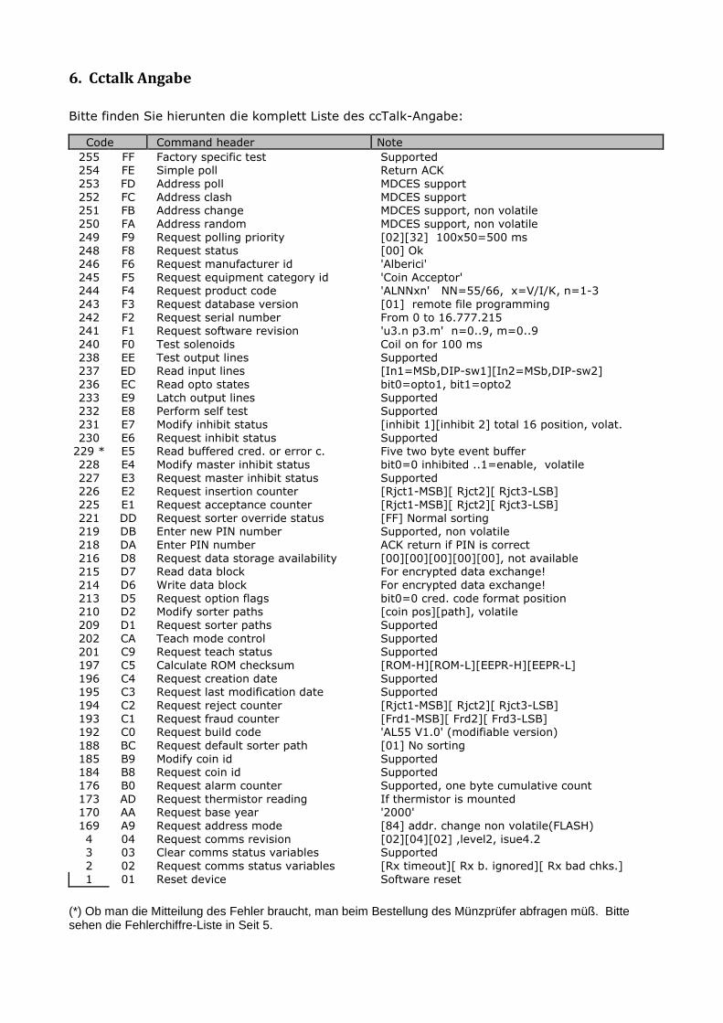
6. Cctalk Angabe
Bitte finden Sie hierunten die komplett Liste des ccTalk-Angabe:
Code Command header Note
255 FF Factory specific test Supported
254 FE Simple poll Return ACK
253 FD Address poll MDCES support
252 FC Address clash MDCES support
251 FB Address change MDCES support, non volatile
250 FA Address random MDCES support, non volatile
249 F9 Request polling priority [02][32] 100x50=500 ms
248 F8 Request status [00] Ok
246 F6 Request manufacturer id 'Alberici'
245 F5 Request equipment category id 'Coin Acceptor'
244 F4 Request product code 'ALNNxn' NN=55/66, x=V/I/K, n=1-3
243 F3 Request database version [01] remote file programming
242 F2 Request serial number From 0 to 16.777.215
241 F1 Request software revision 'u3.n p3.m' n=0..9, m=0..9
240 F0 Test solenoids Coil on for 100 ms
238 EE Test output lines Supported
237 ED Read input lines [In1=MSb,DIP-sw1][In2=MSb,DIP-sw2]
236 EC Read opto states bit0=opto1, bit1=opto2
233 E9 Latch output lines Supported
232 E8 Perform self test Supported
231 E7 Modify inhibit status [inhibit 1][inhibit 2] total 16 position, volat.
230 E6 Request inhibit status Supported
229 * E5 Read buffered cred. or error c. Five two byte event buffer
228 E4 Modify master inhibit status bit0=0 inhibited ..1=enable, volatile
227 E3 Request master inhibit status Supported
226 E2 Request insertion counter [Rjct1-MSB][ Rjct2][ Rjct3-LSB]
225 E1 Request acceptance counter [Rjct1-MSB][ Rjct2][ Rjct3-LSB]
221 DD Request sorter override status [FF] Normal sorting
219 DB Enter new PIN number Supported, non volatile
218 DA Enter PIN number ACK return if PIN is correct
216 D8 Request data storage availability [00][00][00][00][00], not available
215 D7 Read data block For encrypted data exchange!
214 D6 Write data block For encrypted data exchange!
213 D5 Request option flags bit0=0 cred. code format position
210 D2 Modify sorter paths [coin pos][path], volatile
209 D1 Request sorter paths Supported
202 CA Teach mode control Supported
201 C9 Request teach status Supported
197 C5 Calculate ROM checksum [ROM-H][ROM-L][EEPR-H][EEPR-L]
196 C4 Request creation date Supported
195 C3 Request last modification date Supported
194 C2 Request reject counter [Rjct1-MSB][ Rjct2][ Rjct3-LSB]
193 C1 Request fraud counter [Frd1-MSB][ Frd2][ Frd3-LSB]
192 C0 Request build code 'AL55 V1.0' (modifiable version)
188 BC Request default sorter path [01] No sorting
185 B9 Modify coin id Supported
184 B8 Request coin id Supported
176 B0 Request alarm counter Supported, one byte cumulative count
173 AD Request thermistor reading If thermistor is mounted
170 AA Request base year '2000'
169 A9 Request address mode [84] addr. change non volatile(FLASH)
4 04 Request comms revision [02][04][02] ,level2, isue4.2
3 03 Clear comms status variables Supported
2 02 Request comms status variables [Rx timeout][ Rx b. ignored][ Rx bad chks.]
1 01 Reset device Software reset
(*) Ob man die Mitteilung des Fehler braucht, man beim Bestellung des Münzprüfer abfragen müß. Bitte sehen die Fehlerchiffre-Liste in Seit 5.
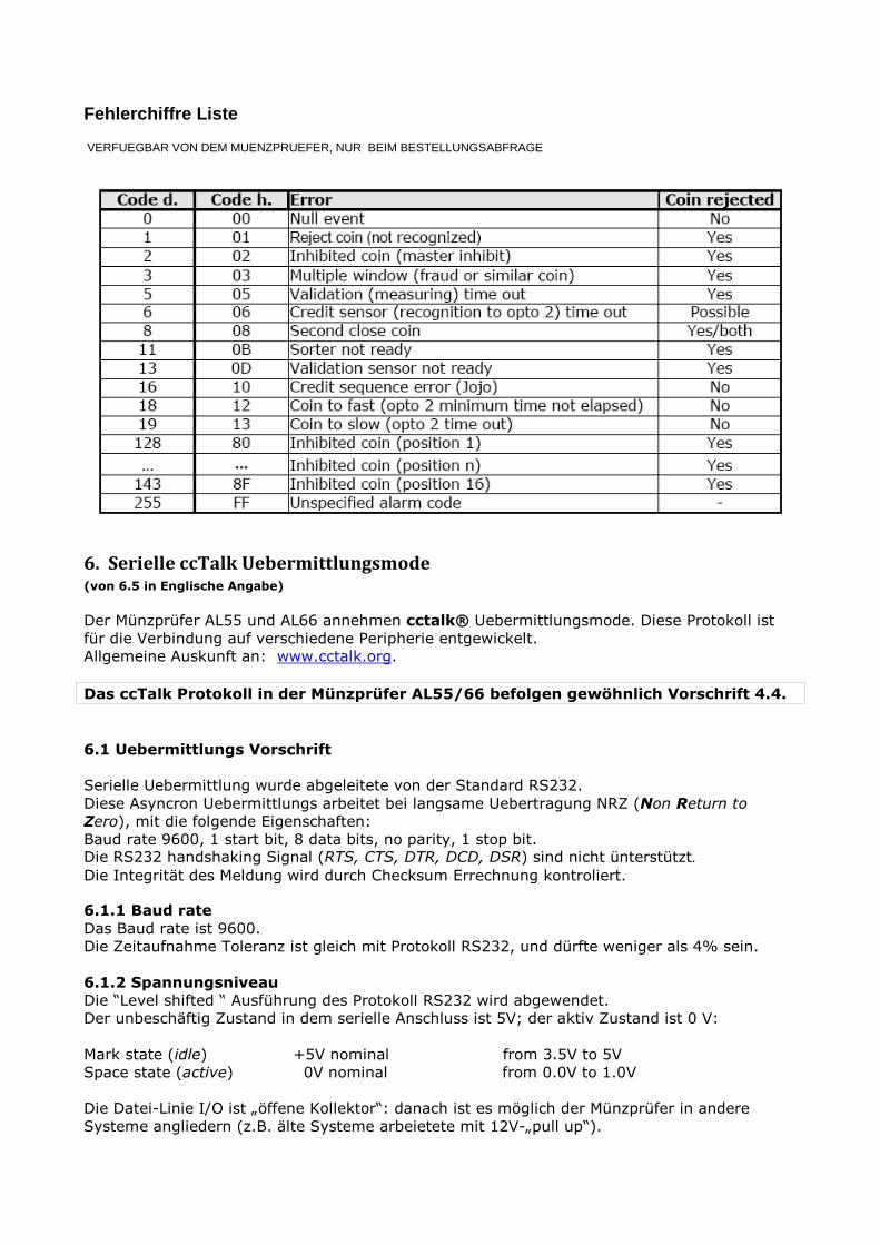
Fehlerchiffre Liste VERFUEGBAR VON DEM MUENZPRUEFER, NUR BEIM BESTELLUNGSABFRAGE
6. Serielle ccTalk Uebermittlungsmode (von 6.5 in Englische Angabe)
Der Münzprüfer AL55 und AL66 annehmen cctalk® Uebermittlungsmode. Diese Protokoll ist
für die Verbindung auf verschiedene Peripherie entgewickelt.
Allgemeine Auskunft an: www.cctalk.org.
Das ccTalk Protokoll in der Münzprüfer AL55/66 befolgen gewöhnlich Vorschrift 4.4.
6.1 Uebermittlungs Vorschrift
Serielle Uebermittlung wurde abgeleitete von der Standard RS232.
Diese Asyncron Uebermittlungs arbeitet bei langsame Uebertragung NRZ (Non Return to
Zero), mit die folgende Eigenschaften:
Baud rate 9600, 1 start bit, 8 data bits, no parity, 1 stop bit. Die RS232 handshaking Signal (RTS, CTS, DTR, DCD, DSR) sind nicht ünterstützt. Die Integrität des Meldung wird durch Checksum Errechnung kontroliert. 6.1.1 Baud rate
Das Baud rate ist 9600.
Die Zeitaufnahme Toleranz ist gleich mit Protokoll RS232, und dürfte weniger als 4% sein.
6.1.2 Spannungsniveau
Die “Level shifted “ Ausführung des Protokoll RS232 wird abgewendet.
Der unbeschäftig Zustand in dem serielle Anschluss ist 5V; der aktiv Zustand ist 0 V:
Mark state (idle) +5V nominal from 3.5V to 5V
Space state (active) 0V nominal from 0.0V to 1.0V
Die Datei-Linie I/O ist „öffene Kollektor“: danach ist es möglich der Münzprüfer in andere
Systeme angliedern (z.B. älte Systeme arbeietete mit 12V-„pull up“).
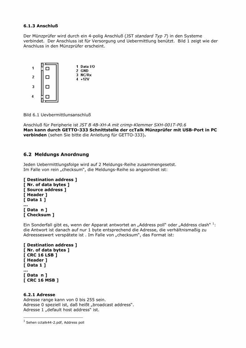
6.1.3 Anschluß
Der Münzprüfer wird durch ein 4-polig Anschluß (JST standard Typ 7) in den Systeme
verbindet. Der Anschluss ist für Versorgung und Uebermittlung benützt. Bild 1 zeigt wie der
Anschluss in den Münzprüfer erscheint.
Bild 6.1 Uevbermittlunsanschluß
Anschluß für Peripherie ist JST B 4B-XH-A mit crimp-Klemmer SXH-001T-P0.6
Man kann durch GETTO-333 Schnittstelle der ccTalk Münzprüfer mit USB-Port in PC
verbinden (sehen Sie bitte die Anleitung für GETTO-333). 6.2 Meldungs Anordnung Jeden Uebermittlungsfolge wird auf 2 Meldungs-Reihe zusammengesetst.
Im Falle von rein „checksum“, die Meldungs-Reihe so angeordnet ist:
[ Destination address ]
[ Nr. of data bytes ]
[ Source address ]
[ Header ]
[ Data 1 ]
...
[ Data n ]
[ Checksum ]
Ein Sonderfall gibt es, wenn der Apparat antwortet an „Address poll“ oder „Address clash“ 1:
die Antwort ist danach auf nur 1 byte entsprechend die Adresse, die verhältnismaßig zu
Adreesseswert verspätete ist . Im Falle von „checksum“, das Format ist:
[ Destination address ]
[ Nr. of data bytes ]
[ CRC 16 LSB ]
[ Header ]
[ Data 1 ]
...
[ Data n ]
[ CRC 16 MSB ] 6.2.1 Adresse
Adresse range kann von 0 bis 255 sein.
Adresse 0 speziell ist, daß heißt „broadcast address“.
Adresse 1 „default host address“ ist.
1 Sehen cctalk44-2.pdf, Address poll
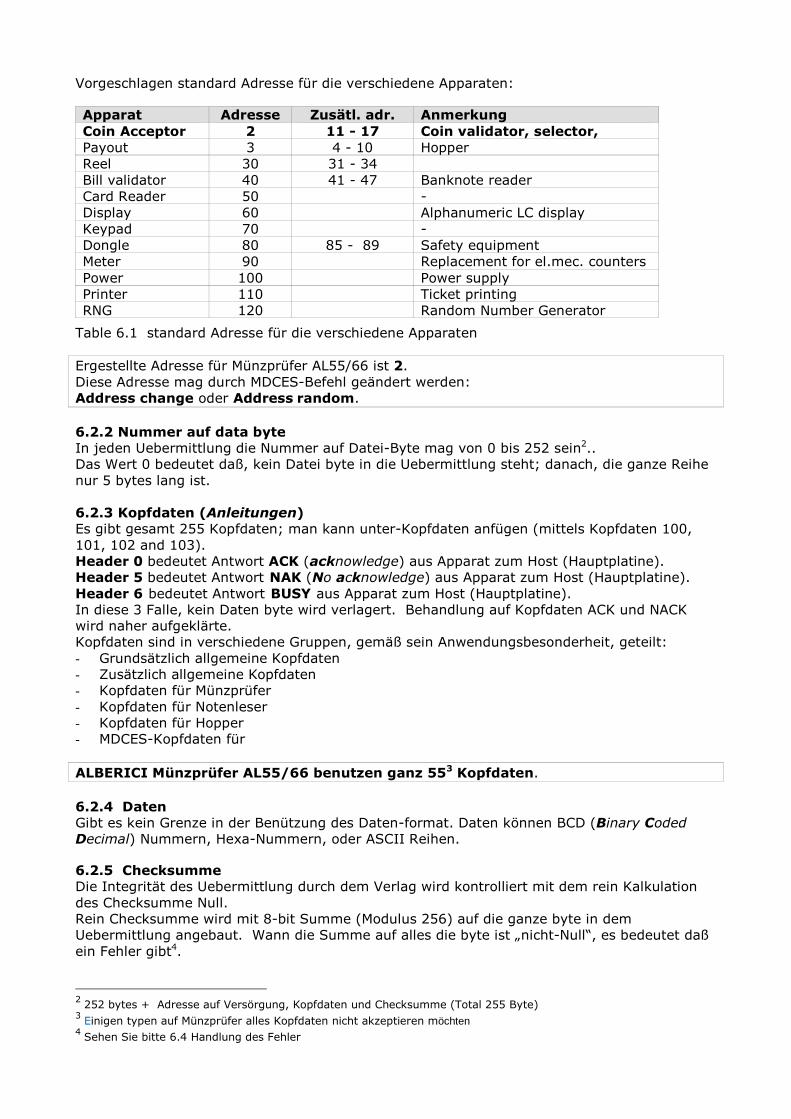
Vorgeschlagen standard Adresse für die verschiedene Apparaten: Apparat Adresse Zusätl. adr. Anmerkung
Coin Acceptor 2 11 - 17 Coin validator, selector,
Payout 3 4 - 10 Hopper
Reel 30 31 - 34
Bill validator 40 41 - 47 Banknote reader
Card Reader 50 -
Display 60 Alphanumeric LC display
Keypad 70 -
Dongle 80 85 - 89 Safety equipment
Meter 90 Replacement for el.mec. counters
Power 100 Power supply
Printer 110 Ticket printing
RNG 120 Random Number Generator
Table 6.1 standard Adresse für die verschiedene Apparaten Ergestellte Adresse für Münzprüfer AL55/66 ist 2.
Diese Adresse mag durch MDCES-Befehl geändert werden:
Address change oder Address random.
6.2.2 Nummer auf data byte
In jeden Uebermittlung die Nummer auf Datei-Byte mag von 0 bis 252 sein2..
Das Wert 0 bedeutet daß, kein Datei byte in die Uebermittlung steht; danach, die ganze Reihe
nur 5 bytes lang ist.
6.2.3 Kopfdaten (Anleitungen)
Es gibt gesamt 255 Kopfdaten; man kann unter-Kopfdaten anfügen (mittels Kopfdaten 100,
101, 102 and 103).
Header 0 bedeutet Antwort ACK (acknowledge) aus Apparat zum Host (Hauptplatine).
Header 5 bedeutet Antwort NAK (No acknowledge) aus Apparat zum Host (Hauptplatine).
Header 6 bedeutet Antwort BUSY aus Apparat zum Host (Hauptplatine).
In diese 3 Falle, kein Daten byte wird verlagert. Behandlung auf Kopfdaten ACK und NACK
wird naher aufgeklärte.
Kopfdaten sind in verschiedene Gruppen, gemäß sein Anwendungsbesonderheit, geteilt:
- Grundsätzlich allgemeine Kopfdaten
- Zusätzlich allgemeine Kopfdaten
- Kopfdaten für Münzprüfer
- Kopfdaten für Notenleser
- Kopfdaten für Hopper
- MDCES-Kopfdaten für
ALBERICI Münzprüfer AL55/66 benutzen ganz 553 Kopfdaten.
6.2.4 Daten Gibt es kein Grenze in der Benützung des Daten-format. Daten können BCD (Binary Coded
Decimal) Nummern, Hexa-Nummern, oder ASCII Reihen. 6.2.5 Checksumme
Die Integrität des Uebermittlung durch dem Verlag wird kontrolliert mit dem rein Kalkulation
des Checksumme Null.
Rein Checksumme wird mit 8-bit Summe (Modulus 256) auf die ganze byte in dem
Uebermittlung angebaut. Wann die Summe auf alles die byte ist „nicht-Null“, es bedeutet daß
ein Fehler gibt4.
2 252 bytes + Adresse auf Versörgung, Kopfdaten und Checksumme (Total 255 Byte) 3 Einigen typen auf Münzprüfer alles Kopfdaten nicht akzeptieren möchten 4 Sehen Sie bitte 6.4 Handlung des Fehler
Für Anwendungsfall in Storung-laden Umfeld, oder für Höhe Sicherheit Anwendung, möglich ist
mehr verzweigt 16-bit CRC CCITT Checksumme zu benutzen, z.B.:
x16 + x12 + x5 + 1 und anfänglich Wert auf CRC-Register 0x0000.
Nach Kunden-Anfrage, die Münzprüfer AL55/66 können so eingestellt werden, sodaß mit CRC-
16 Checksumme laufen können.
6.3 Anweise über Zeitmessung Zeitmessung ist nicht sehr kritisch bezüglich ccTalk Protokoll, aber einigen wichtige
Vorgeshlagen befolgt müßen. 6.3.1 Zeit zwischen zwei byte
Während die Erhaltung auf ein Uebermittlungs-Reihe, die Software müß bis 50 msek. für
nächste byte warten. Wenn „Time-out „ kommt, die Software müß alles mitteilung abbrechen
und für nächste Uebermittlung warten. Während die Uebermittlung, die Spätung zwischen die
byte müßt weniger als 2 msek., und nicht mehr als 10 msek., sein. 6.3.2 Zeit zwischen Befehl und Antwort
Späteste Antwort müßt in max 10 msek. erhaltet werden. Die Antwort an die Befehlen, die der
Betrieb eines Funktion in den Münzprüfer aktivieren, nach die Funktion geendet wird, antreten
können5.
6.3.3 Anlauf Zeit
Nach dem Einschaltung, der Münzprüfer bereit zum einen ccTalk Meldung in weniger als 250
msek. akzeptieren und antworten sollte. 6.4 Fehler Behandlung Ob der Münzprüfer einen Meldung mit falsch Checksumme (oder mit vermisst Datei) erhaltet,
der Empfangs-Zwischenspeicher wird ausgelöscht. Der Hauptplatine sollte dann die Meldung
wieder absenden.
6.5 Command headers (Englische Sprache)
Command header set, that host could use in communication with coin selectors AL55 and AL66
is given in the table 6.2.
Command headers are divided in to 3 different groups:
- Common command headers
- Coin acceptor command headers
- MDCES command headers Code Command header Note
255 FF Factory specific test Supported
254 FE Simple poll Return ACK
253 FD Address poll MDCES support
252 FC Address clash MDCES support
251 FB Address change MDCES support, non volatile
250 FA Address random MDCES support, non volatile
249 F9 Request polling priority [02][32] 100x50=500 ms
248 F8 Request status [00] Ok
246 F6 Request manufacturer id 'Alberici'
245 F5 Request equipment category id 'Coin Acceptor'
244 F4 Request product code 'ALNNxn' NN=55/66, x=V/I/K, n=1-3
243 F3 Request database version [01] remote file programming
5 Z.B. mehr als 100 msek. für die Verfprüfung des Spule.
242 F2 Request serial number From 0 to 16.777.215
241 F1 Request software revision 'u3.n p3.m' n=0..9, m=0..9
240 F0 Test solenoids Coil on for 100 ms
238 EE Test output lines Supported
237 ED Read input lines [In1=MSb,DIP-sw1][In2=MSb,DIP-sw2]
236 EC Read opto states bit0=opto1, bit1=opto2
233 E9 Latch output lines Supported
232 E8 Perform self test Supported
231 E7 Modify inhibit status [inhibit 1][inhibit 2] total 16 position, volat.
230 E6 Request inhibit status Supported
229 E5 Read buffered cred. or error c. Five two byte event buffer
228 E4 Modify master inhibit status bit0=0 inhibited ..1=enable, volatile
227 E3 Request master inhibit status Supported
226 E2 Request insertion counter [Rjct1-MSB][ Rjct2][ Rjct3-LSB]
225 E1 Request acceptance counter [Rjct1-MSB][ Rjct2][ Rjct3-LSB]
221 DD Request sorter override status [FF] Normal sorting
219 DB Enter new PIN number Supported, non volatile
218 DA Enter PIN number ACK return if PIN is correct
216 D8 Request data storage availability [00][00][00][00][00], not available
215 D7 Read data block For encrypted data exchange!
214 D6 Write data block For encrypted data exchange!
213 D5 Request option flags bit0=0 cred. code format position
210 D2 Modify sorter paths [coin pos][path], volatile
209 D1 Request sorter paths Supported
202 CA Teach mode control Supported
201 C9 Request teach status Supported
197 C5 Calculate ROM checksum [ROM-H][ROM-L][EEPR-H][EEPR-L]
196 C4 Request creation date Supported
195 C3 Request last modification date Supported
194 C2 Request reject counter [Rjct1-MSB][ Rjct2][ Rjct3-LSB]
193 C1 Request fraud counter [Frd1-MSB][ Frd2][ Frd3-LSB]
192 C0 Request build code 'AL66 V1.0'
188 BC Request default sorter path [01] No sorting
185 B9 Modify coin id Supported
184 B8 Request coin id Supported
176 B0 Request alarm counter Supported, one byte cumulative count
173 AD Request thermistor reading If thermistor is mounted
170 AA Request base year '2000'
169 A9 Request address mode [84] addr. change non volatile(FLASH)
4 04 Request comms revision [02][04][02] ,level2, isue4.2
3 03 Clear comms status variables Supported
2 02 Request comms status variables [Rx timeout][ Rx b. ignored][ Rx bad chks.]
1 01 Reset device Software reset
Table 6.2 cctalk instruction header list
6.5.1 Common command headers Common commands are used in all type of devices to detect there presence on cctalk network
or to describe them. Information like: manufacturer or product type id, serial number, different
settings etc. are transmitted to host. 6.5.1.1 Command 254 [hexFE], Simple poll
The fastest way for host to detect all attached devices in cctalk network.
Addressed device-coin selector respond with ACK (Acknowledge).
If within predicted amount of time Coin selector does not respond coin selector is probably not
connected, powered or simple not working properly.
Message format is: Host sends: [Dir] [00] [01] [FE] [Chk]
Coin s. respond: [01] [00] [Dir] [00] [Chk]
As coin selector default address is 2, example of message string is: Host sends: [02] [00] [01] [FE] [FF]
Coin s. respond: [01] [00] [02] [00] [FD] ACK mesage
6.5.1.2 Command 246 [hexF6], Request manufacturer ID
Coin selector respond with ASCII string representing manufacturer name.
Message format is: Host sends: [Dir] [00] [01] [F6] [Chk]
Coin s. respond: [01] [Nr.b] [Dir] [00] [a1] [a2] . . . . [an] [Chk]
Nr. b is number of data bytes-characters sent by coin selector, and a1 to an are ASCII
characters. For Alberici coin selector example of message string is: Host sends: [02] [00] [01] [F6] [07]
Coin s. respond: [01] [08] [02] [00] [41][6C][62][65][72][69][63][69 ] [DA]
6.5.1.3 Command 245 [hexF5], Request equipment category ID
Respond to command header is standardized name for coin selectors, coin validators or coin
mechs. Coin selector respond with ASCII string of characters representing standardized name
for that type of device Coin Acceptor.
Message format is: Host sends: [Dir] [00] [01] [F5] [Chk]
Coin s. respond: [01] [0D] [Dir] [00] [43][6F][69][6E][20][41][63][ 63][65][70][74][6F][72] [Chk]
Number of data byte is always 13, hex [0D].
Example of message string for coin selector(address 2) is: Host sends: [02] [00] [01] [F5] [08]
Coin s. respond: [01] [0D] [02] [00] [43][6F][69][6E][20][41][63][63 ][65][70][74][6F][72] [16]
6.5.1.4 Command 244 [hexF4], Request product code
Coin selector respond with ASCII string of character, representing the factory type of coin
selector. For ALBERICI coin selectors of new generation possible response will be:
- AL55V1, AL55K1, AL55I1
- AL66V2, AL66K3, AL66I3
In special version for italian gambling machines response is allways AL05V-c .
Host sends: [Dir] [00] [01] [F4] [Chk]
Coin s. respond: [01] [07] [Dir] [00] [a1][a2] . . . [a7] [Chk]
Number of data bytes sent by coin selector is 6 or 7, hex [07].
Example of message string for coin selector(address 2) type AL06V-c is:
Host sends: [02] [00] [01] [F4] [09]
Coin s. respond: [01] [07] [02] [00] [41][4C][30][36][56][2D][63] [ 1D]
6.5.1.5 Command 242 [hexF2], Request serial number
Coin selector respond with three byte serial number. Message format is: Host sends: [Dir] [00] [01] [F2] [Chk]
Coin s. respond: [01] [03] [Dir] [00] [Serial 1 - LSB] [Serial 2] [S erial 3 - MSB] [Chk]
Serial 1 – first data byte sent is LSB of serial number.
Example of message string for coin selector(address 2) with serial number: 1234567 (hex
[BC][61][4E]) is: Host sends: [02] [00] [01] [F2] [0B]
Coin s. respond: [01] [03] [02] [00] [4E][61][BC] [8F]
6.5.1.6 Command 241 [hexF1], Request software revision Coin selector return ASCII string of character representing software version and revision.
Message format is: Host sends: [Dir] [00] [01] [F1] [Chk]
Coin s. respond: [01] [Nr.b] [Dir] [00] [a1] [a2].... [an] [Chk]
Number of data bytes in ASCII string is not limited and each producer has it’s own system of
labelling. Example of message string for coin selector(address 2) is: Host sends: [02] [00] [01] [F1] [0C]
Coin s. respond: [01] [09] [02] [00] [75][31][2E][30][20][70][31][2 E][30][2E][30] [71]
Coin selector respond is ‘u1.0 p1.0.0’.
ALBERICI coin selectors has program firmware label divided in two parts.
First label u is for protected FLASH memory program(monitor program) revision.
First digit is for major changes and second for minor changes. In this case it is u1.0.
Second label is revision of main program FLASH memory.
Main program software revision labelling use 3 digits. First most significant digit is for major
software changes, second is for minor software changes and third for “bug” correction. In this
case it is u1.0.0.
6.5.1.7 Command 197 [hexC5], Calculate ROM checksum
Coin selector respond with four bytes of micro controller internal memory checksum. First two
bytes are program ROM CRC and the second is data EEPROM CRC. Any changes in program or
data will change the respond of coin selector.
Message format is: Host sends: [Dir] [00] [01] [C5] [Chk]
Coin s. respond: [01] [4] [Dir] [00] [CRC1-H][CRC1-L] [CRC2-H] [CRC2 -L] [Chk]
Example of message string for coin selector(address 2) is: Host sends: [02] [00] [01] [C5] [38]
Coin s. respond: [01] [04] [02] [00] [D9][2A][7E][79] [96]
6.5.1.8 Command 192 [hexC0], Request build code
Coin selector respond with ASCII string of character representing it’s hardware version and
revision. Last revision of printed circuit board for coin selectors AL55/66 is:
AL66 V1.0. Message format is: Host sends: [Dir] [00] [01] [C0] [Chk]
Coin s. respond: [01] [Nr.b] [Dir] [00] [a1] [a2].... [an] [Chk]
Example of message string for coin selector(address 2) is: Host sends: [02] [00] [01] [C0] [3D]
Coin s. respond: [01] [09] [02] [00] [41][4C][2D][30][35][20][56][3 5][30] [FA]
6.5.1.9 Command 169 [hexA9], Request address mode
Coin selector respond with one byte data6 information about addressing mode. Address could
be stored in different type of memory(RAM. ROM or EEPROM), set with DIP-switch at printed
circuit board or hard-wired at external connectors. Some devices support address change wit
MDCES command headers7. Message format is: Host sends: [Dir] [00] [01] [A9] [Chk]
Coin s. respond: [01] [01] [Dir] [00] [Address mode] [Chk]
6 Details of description see in public document cctalk44-2.pdf 7 Address change, Address random
ALBERICI coin selector has address is stored in non-volatile memory(FLASH) and address
change is supported.
Example of message string for coin selectors(address 2) is: Host sends: [02] [00] [01] [A9] [54]
Coin s. respond: [01] [01] [02] [00] [84] [78]
6.5.1.10 Command 4 [hex04], Request comms revision
Coin selector respond with three byte data information about level of cctalk protocol
implementation, major and minor revision. Message format is: Host sends: [Dir] [00] [01] [04] [Chk]
Coin s. respond: [01] [03] [Dir] [00] [Level] [Mag.rev.] [min. rev. ] [Chk]
Example of message string for coin selector(address 2) with level of implementation 1, cctalk
protocol issue 4.4 is: Host sends: [02] [00] [01] [04] [F9]
Coin s. respond: [01] [03] [02] [00] [01][04][04] [F1]
6.5.1.11 Command 3 [hex03], Clear comms status variables
After acceptance of command header 3, coin selector clears all three bytes of communication
errors counters and respond with ACK message. Message format is: Host sends: [Dir] [00] [01] [03] [Chk]
Coin s. respond: [01] [00] [Dir] [00] [Chk] ACK mesage
Example of message string for coin selector(address 2) is: Host sends: [02] [00] [01] [03] [FA]
Coin s. respond: [01] [00] [02] [00] [FD] ACK mesage
6.5.1.12 Command 2 [hex02], Request comms status variables
Coin selector respond with three byte data representing communication errors.
First byte is receive time out counter, second byte is number of ignored receive bytes8 and
third byte is number of checksum errors. Message format is: Host sends: [Dir] [00] [01] [02] [Chk]
Coin s. respond: [01] [03] [Dir] [RxErr1] [RxErr2] [RxErr3] [Chk]
Example of message string for coin selector(address 2) with no errors is: Host sends: [02] [00] [01] [02] [FB]
Coin s. respond: [01] [03] [02] [00] [00] [00] [00] [FA]
6.5.1.13 Command 1 [hex01], Reset device
After acceptance of Reset command, coin selector execute software reset and clear all
variables in RAM or set them at default value, including different counters and credit buffer.
ACK message is sent before reset of coin selector. Host software must set again:
- inhibit state
- sorter path
- master inhibit (if necessary)
Message format is: Host sends: [Dir] [00] [01] [01] [Chk]
Coin s. respond: [01] [00] [Dir] [00] [Chk] ACK mesage
Example of message string for coin selector(address 2) is: Host sends: [02] [00] [01] [01] [FC]
Coin s. respond: [01] [00] [02] [00] [FD] ACK mesage
Host software must wait at least 100 ms, to continue comunication with coin selector after
reset instruction!
8 Number of receive buffer overflow bytes.
6.5.2 Coin acceptor specific command headers
Coin selectors use some specific commands, mostly for control of coin input, acceptance and
direction9.
Some commands are shared with other device like banknote reader or payout device.
6.5.2.1 Command 249 [hexF9], Request polling priority
Basic principle of detecting credit input or eventual errors from coin selector is sequential
polling10. Coin selectors due to differences in mechanical and electrical construction has
different acceptance speed. All events are registered in memory buffer with limited size11 . To
avoid credit loss, host must read coin selector credit buffer within limited time period. Coin
selector has internal mechanism to block the coin acceptance and registration of all events if
polling time elapse.
For ALBERICI coin selector acceptance speed is from 3 to 4 coins per second12.
Considering that it is possible to register 5 event in the buffer, the adequate polling time will
be about 1 sec. Because of necessity to register even “close” and non accepted coins polling
time must be even shorter.
For ALBERICI coin selectors AL55/66 using cctalk interface, poll time is set to 500 ms.
Coin selectors that use standard 10 pole interface are not necessary to poll.
In that case polling time unit is set to 0(no polling)!
Minimum time for polling must not be shorter than overall message time13.
Coin selector respond to command with two bytes of data. First byte is poll time unit and
second is polling time value14. Message format is: Host sends: [Dir] [00] [01] [F9] [Chk]
Coin s. respond: [01] [01] [Dir] [Time] [Chk]
Example of message string for coin selector(address 2) is: Host sends: [02] [00] [01] [F9] [04]
Coin s. respond: [01] [02] [02] [00] [02] [32] [C7]
First byte 02 is unit x10ms , and second byte is time value hex32 = 50.
Polling time is calculated as:
T = 10 x 50 = 500 ms
6.5.2.2 Command 248 [hexF8], Request Status
ALBERICI coin selectors has no additional COS15 and return mechanism.
Response to that command is always hex[00], coin selector Ok.
Example of message string for coin selector(address 2) is:
Host sends: [02] [00] [01] [F8] [05]
Coin s. respond: [01] [01] [02] [00] [00] [FC]
6.5.2.3 Command 243 [hexF3], Request data base version
The respond to that command is version of coin data base. Version of data base is important
for coin selectors with remote programming support.
For all ALBERICI coin selectors type AL55/66 current data base version is 00.
Message format is: Host sends: [Dir] [00] [01] [F3] [Chk]
Coin s. respond: [01] [01] [Dir] [Ver.] [Chk]
9 Sorter control commands 10 Reading memory buffer from coin selector 11 Five stage double byte memory buffer 12 Dependant on mechanical type of coin selector (K, S type is faster ) and coin 13 For coin selector with respond time 2 ms and byte gap 1 ms it is 38 ms 14 For details see, cctalk44-2.pdf 15
Coin On String
Example of message string for coin selector(address 2) is: Host sends: [02] [00] [01] [F3] [0A]
Coin s. respond: [01] [01] [02] [00] [00] [FC]
6.5.2.4 Command 240 [hexF0], Test solenoids
Host sends one byte mask to determinate which solenoid must be tested.
Coin selector accept gate solenoid or sorter solenoid will be switched on for period of 100 ms
and after that, ACK message will be transmitted. Message format is: Host sends: [Dir] [01] [01] [F0] [Mask.] [Chk]
Coin s. respond: [01] [00] [Dir] [00] [Chk] ACK
Example of message string for coin selector(address 2) acceptance gate test is: Host sends: [02] [01] [01] [F0] [01] [0B]
Coin s. respond: [01] [00] [02] [00] [FD] Single click -> 100 ms, ACK
Bit position for output that is used to drive sorter coil are:
bit 0 = accept gate coil
bit 1 = sorter coil “A”(out 6/pin 4)
bit 2 = sorter coil “B”(out 5/pin 3)
bit 3 = sorter coil “C”(out 4/pin 10)
If output selected with bit in mask is not programmed for sorter activation it will not be
activated but coin selector will still response with ACK.
6.5.2.5 Command 238 [hexEE], Test output lines
Host sends one byte mask to determinate which output line must be tested.
Coin selector output line that correspond to bit set in the mask will be pulsed for 100 ms and
after that, ACK message will be transmitted. Message format is: Host sends: [Dir] [01] [01] [EE] [Mask.] [Chk]
Coin s. respond: [01] [00] [Dir] [00] [Chk] ACK
Example of message string for coin selector(address 2) first output(pin7) is: Host sends: [02] [01] [01] [EE] [01] [0D]
Coin s. respond: [01] [00] [02] [00] [FD] Single pulse out 1 -> 100 ms, ACK
Bit positions for output test are:
- bit 0 Output 1(pin 7)
- bit 1 Output 2(pin 8)
- bit 2 Output 3(pin 9)
- bit 3 Output 4(pin 10)
- bit 4 Output 5(pin 3)
- bit 5 Output 6(pin 4)
- bit 6 Output 7(pin 5)
- bit 7 Not used
Unused output (not programmed) will not be turned on, but message ACK will be returned.
6.5.2.6 Command 237 [hexED], Read input lines
Coin selector respond with two data byte representing the state of DIP-switches and state of
inputs In1(pin 6) and In2(pin 5)16.
ALBERICI coin selectors has one or two banks of DIP-switches for various data or operating
modes setting. First data byte is state of first DIP-switch(bank 1) and In1, wile second
represent second DIP-switch(bank 2) and In2. LSb is first switch in bank and MSb is state of
input. Switch closed state is represented with logic “1”, and input active state is logic “1”.
Message format is: Host sends: [Dir] [00] [01] [ED] [Chk]
Coin s. respond: [01] [02] [Dir] [Mask1] [Mask2] [Chk]
Example of message string for coin selector(address 2), with all switches “off” and inputs not
active is: Host sends: [02] [00] [01] [ED] [10]
16
If In2 is programmed as input
Coin s. respond: [01] [02] [02] [00] [00] [00] [FB]
Example of message string for coin selector(address 2), with all switches “on” and input
1(inhibit acceptance) active is: Host sends: [02] [00] [01] [ED] [10]
Coin s. respond: [01] [02] [02] [00] [BF] [00] [3C]
6.5.2.7 Command 236 [hexEC], Read opto states Coin selector respond with one data byte representing the state of opto pairs.
ALBERICI coin selectors has up to 3 pairs of optical sensor17 for detection of coin position,
speed and direction and 2 pairs of opto sensors for diameter measurement.
Bit position for opto pairs are:
- bit 0 Diam. measure opto 1
- bit 1 Diam. measure opto 2
- bit 2 Control opto 1
- bit 3 Control opto 2
- bit 4 Control opto 3
- bit 5 Not used
- bit 6 Not used
- bit 7 Not used
Control opto sensor 2 is called “credit” opto sensor exist in all version of coin selectors and it is
placed after the acceptance gate. Other pairs are optional and some coin selectors has 2 and
some 3 control optical pairs. Number of control pairs make part of coin selector type label.
For example coin selector type AL66V2 has 2 control opto sensor pairs. The unused bits or non
existing optical sensors are always read as 0.
Interruption of light barrier of opto sensor correspond to bit value 1.
Message format is: Host sends: [Dir] [00] [01] [EC] [Chk]
Coin s. respond: [01] [01] [Dir] [Mask.] [Chk]
Example of message string for coin selector(address 2) with opto sensors cleared is: Host sends: [02] [00] [01] [EC] [11]
Coin s. respond: [01] [01] [02] [00] [00] [FC]
6.5.2.8 Command 233 [hexE9], Latch output lines
This instruction is similar to instruction 238. Host sends one byte mask to determinate which
output line must be activated(latch). ACK message will be transmitted immediate.
Coin selector output line that correspond to bit set in the mask will be latched and active till
reset or new instruction with bit cleared is sent. Message format is: Host sends: [Dir] [01] [01] [E9] [Mask.] [Chk]
Coin s. respond: [01] [00] [Dir] [00] [Chk] ACK
Example of message string for coin selector(address 2) first output(pin7) is: Host sends: [02] [01] [01] [E9] [01] [12]
Coin s. respond: [01] [00] [02] [00] [FD] Latch out 1 -> ACK
6.5.2.9 Command 232 [hexE8], Perform self-test
Coin selector respond to command with one or two bytes of data according to
table 6.3. First byte is fault code and second is optional data, usually representing fault sensor
number(from 1 to 3).
17
In some case group could contain more than one opto pairs
Code Fault Optional data Comment
0 OK No fault detected - -
2 Fault on inductive sensor Sensor number -
3 Fault on credit sensor - Control opto sensor 2
6 Fault on diameter sensor - -
18 Fault on reject sensor - Control opto sensor 3
33 Power supply out of limits - -
34 Temperature out of limit - Optional
255 Unspecified fault code - -
Table 6.3 Fault codes for AL55/66 coin selectors
Inductive sensor numbers are:
01 Upper inductive sensor
02 First lower inductive sensor
03 Second lower inductive sensor
Message format is: Host sends: [Dir] [00] [01] [E8] [Chk]
Coin s. respond: [01] [01/02] [Dir] [Fault c.][Data opt.] [Chk]
Example of message string for coin selector(address 2) with no fault detected is: Host sends: [02] [00] [01] [E8] [15]
Coin s. respond: [01] [01] [02] [00] [00] [FC] No fault detected
Example of message string for coin selector(address 2) with first lower sensor fault detected
is: Host sends: [02] [00] [01] [E8] [15]
Coin s. respond: [01] [02] [02] [00] [02][02] [F7] Fault on first lower sensor detected
6.5.2.10 Command 231 [hexE7], Modify inhibit status
With this command host is able to inhibit the acceptance of some or all coins.
Acceptance or inhibition is set with a two byte mask sent by host.
Bits from 0 do 15 determinate coin positions from 1 to 1618.
Number of coin channels in new ALBERICI coin selectors AL55/66 is same as number of
position(16). Message format is: Host sends: [Dir] [02] [01] [E7] [LSB Mask.] [MSB Mask.] [Chk]
Coin s. respond: [01] [00] [Dir] [00] [Chk] ACK
Example of message string to enable all position for coin selector(address 2) is: Host sends: [02] [02] [01] [E7] [FF] [FF] [16]
Coin s. respond: [01] [00] [02] [00] [FD] ACK
After that all programmed coins will be enabled. Command has no effect on coin position that
are not programmed. Initially coin channels could be programmed with acceptance enabled or
disabled.
For coin selectors that are using only cctalk interface, all coins position must be
initially inhibited!
18 Positions are sent by coin selector during reading credit buffer or error codes (header 229)
6.5.2.11 Command 230 [hexE6], Request inhibit status
Coin selector respond with two byte data that correspond to inhibit state mask for all 16
positions of coin. If bit value is 1 acceptance of coin in that position is enabled. If bit value is 0
coin is inhibited. Message format is: Host sends: [Dir] [02] [00] [E6] [Chk]
Coin s. respond: [01] [02] [Dir] [00] [LSB Mask.] [MSB Mask.] [Chk]
Example of message string for coin selector(address 2) AL06V-c19 after power-up or reset is: Host sends: [02] [00] [01] [E6] [17]
Coin s. respond: [01] [02] [02] [00] [00] [00] [FB]
Example of message string for coin selector(address 2) with programmed positions from 1 to
6, after receiving command to enable acceptance of all 16 position is: Host sends: [02] [00] [01] [E6] [17]
Coin s. respond: [01] [02] [02] [00] [3F] [00] [BC]
First byte represent the mask for coin positions 1 to 8 and second for 9 to 16.
Coin channels(positions) that are not programmed are always represented as zero bit!
6.5.2.12 Command 229 [hexE5], Read buffered credit or error codes
This is the most important command used by host to detect import of coins in to a machine
and to report eventual errors. As previously mentioned coin selectors store all events in
volatile memory called credit buffer. Buffer has 5 level and use two bytes for each event. In
first byte coin position or coin value20 is stored. The second byte point to a sorter path or
indicate error code.
If during coin acceptance any error occurs, stored value of coin position is 0, hex [00].
Error codes supported in ALBERICI coin selectors AL55/66 are shown in table 6.4. Code d. Code h. Error Coin rejected
0 00 Null event No
1 01 Reject coin (not recognized) Yes
2 02 Inhibited coin (master inhibit) Yes
3 03 Multiple window (fraud or similar coin) Yes
5 05 Validation (measuring) time out Yes
6 06 Credit sensor (recognition to opto 2) time out Possible
8 8 Second close coin Yes/both
16 10 Credit sequence error (Yo-yo) No
18 12 Coin to fast (opto 2 minimum time not elapsed) No
19 13 Coin to slow (opto 2 time out) No
128 80 Inhibited coin (position 1) Yes
… … Inhibited coin (position n) Yes
143 8F Inhibited coin (position 16) Yes
255 FF Unspecified alarm code -
Table 6.4 Acceptance error codes
Coin selectors also use one eight bit counter21 that is incremented each time a new coin is
detected. At the same time data in coin credit buffer are shifted two position to the right.
When counter reaches the value of 255 it toggle to a value 1 and continue to increment on
each event. Event counter is set to value “0” after each power-up or acceptance of reset
command. The first two byte (LSB) in coin credit buffer always contain the data of last event.
Host software must read event counter and coin credit buffer data in period short enough to
prevent the loss of coin data22. Message format is: Host sends: [Dir] [00] [00] [E5] [Chk]
19
Coin selector for Italian gambling machines 20 If coin selector use CVF (Coin Value Format) 21 Event counter 22
See command 249 Request polling priority
Coin s. respond: [01][0B] [Dir] [00] [Ev.cnt.][coin code 1][dir /err] [coin code 2][dir/err] . . .
. . . [coin code 5][dir /err] [Chk]
Examples of message string for coin selector(address 2) after coin insertions: Host sends: [02] [00] [00] [E5] [18] Polling minimum each 500 ms
Coin s. respond: [01] [0B] [02] [00] [00][00][00][00][00][00][00][0 0][00][00][00] [F2]
The respond after power-up or reset
Coin s. respond: [01] [0B] [02] [00] [01][01][02][00][00][00][00][0 0][00][00][00] [EE]
First event, coin possition 1, sorter path 2 accepted
Coin s. respond: [01] [0B] [02] [00] [02][02][01][ 01][02][00][00][ 00][00][00][00] [EA]
Second event, coin possition 2, sorter path 1 accepted
Coin s. respond: [01] [0B] [02] [00] [03][00][02][02][01][01][02][0 0][00][00][00] [E7]
Third event, coin rejected due to master inhibit active
Coin s. respond: [01] [0B] [02] [00] [04][00][83][ 00][02][02][01][ 01][02][00][00] [63]
Forth event, coin possition 4 inhibited and rejected
From example we can notice shifting of data in the coin credit and error buffer and increment
of event counter. 6.5.2.13 Command 228 [hexE4], Modify master inhibit status
This command is used to inhibit acceptance of all coins and has same effect as command
modify inhibit status with sent with two bytes of zeros. Host sends only one byte of data. If
first bit (LSb) is set to “0” coin selector is inhibited. Bits 1 to 7 has no influence to coin
selector. Message format is: Host sends: [Dir] [01] [01] [E4] [Mask.] [Chk]
Coin s. respond: [01] [00] [Dir] [00] [Chk] ACK
Initially coin selectors are programmed with acceptance enabled.
Change is stored in RAM location .
On customer demand it is possible to set inhibition as default .
Example of message string to inhibit the acceptance for coin selector(address 2) is: Host sends: [02] [01] [01] [E4] [00] [18]
Coin s. respond: [01] [00] [02] [00] [FD] ACK
After that coin selector acceptance will be inhibited till reset or next instruction that will change
master inhibit status.
6.5.2.14 Command 227 [hexE3], Request master inhibit status
Coin selector respond with one byte data information of main inhibit status.
Only first (LSb) bit is used. If bit 0 is “1” acceptance is enabled, and if bit 0 is “0” coin selector
is inhibited and acceptance is disabled.
Other bits has no meaning and always read as “0”. Message format is: Host sends: [Dir] [00] [00] [E3] [Chk]
Coin s. respond: [01] [01] [Dir] [00] [Mask.] [Chk]
Example of message string for coin selector(address 2) after power-up is: Host sends: [02] [00] [01] [E3] [1A]
Coin s. respond: [01] [01] [02] [00] [01] [FB] Acceptance enabled (default)
Example of message string for coin selector(address 2) after activation of master inhibit23 is: Host sends: [02] [00] [01] [E3] [1A]
Coin s. respond: [01] [01] [02] [00] [00] [FC] Coin selector inhibited
23 Using command 210, Modify master inhibit status
6.5.2.15 Command 226 [hexE2], Request insertion counter Coin selector respond with three bytes of insertion counter data.
First byte is LS byte of three byte counter in RAM. Insertion counter is set to zero after power
up or reset command. It is incremented each time a new coin is inserted in to coin acceptor.
Message format is: Host sends: [Dir] [00] [00] [E2] [Chk]
Coin s. respond: [01] [03] [Dir] [00] [Cunt1-LSB] [Cunt2] [Cunt3-MS B] [Chk]
Example of message string for coin selector(address 2) after power-up is: Host sends: [02] [00] [01] [E2] [1B]
Coin s. respond: [01] [03] [02] [00] [00] [00] [00] [FA]
6.5.2.16 Command 225 [hexE1], Request accept counter Coin selector respond with three bytes of acceptance counter data.
First byte is LS byte of three byte counter in RAM. Acceptance counter is set to zero after
power up or reset command. It is incremented each time a new coin pass acceptance sensor24.
Message format is: Host sends: [Dir] [00] [00] [E1] [Chk]
Coin s. respond: [01] [03] [Dir] [00] [Cunt1-LSB] [Cunt2] [Cunt3-MS B] [Chk]
Example of message string for coin selector(address 2) after power-up is: Host sends: [02] [00] [01] [E1] [1C]
Coin s. respond: [01] [03] [02] [00] [00] [00] [00] [FA]
6.5.2.17 Command 221 [hexDD], Request sorter override status
Coin selectors AL55/66 do not support override of sorter path.
Coin selector respond will be always: hex[FF] – Normal sorting.
Example of message string for coin selector(address 2) is: Host sends: [02] [00] [01] [DD] [20]
Coin s. respond: [01] [01] [02] [00] [FF] [FD]
6.5.2.18 Command 219 [hexDB], Enter new PIN number
Host send four byte data of new PIN number. If correct PIN was previously received25 coin
selector will accept the new PIN and respond with ACK message Coin selectors AL06x-c has
PIN number stored in EEPROM. Message format is: Host sends: [Dir] [04] [01] [DB] [PIN1-LSB][PIN2][PIN3][PIN4-M SB] [Chk]
Coin s. respond: [01] [00] [02] [00] [FD] ACK if PIN is correct
Coin s. respond: no respond if PIN is incorrect or not recieved
Example of message string for coin selector(address 2) with default PIN:
hex[00][00][00][00] previously received and NEW pin hex[01][02][03][04] is:
Host sends: [02] [04] [01] [DB] [01][02][03][04] [14]
Coin s. respond: [01] [00] [02] [00] [FD] ACK message
6.5.2.19 Command 218 [hexDA], Enter PIN number
Host send four byte data of PIN number. If PIN is correct, coin selector will respond
immediately with ACK message. If PIN is incorrect the NAK message will be sent with time
delay of 100 ms. Coin selectors AL06x-c has PIN number stored in EEPROM. Message format
is: Host sends: [Dir] [04] [01] [DA] [PIN1-LSB][PIN2][PIN3][PIN4-M SB] [Chk]
Coin s. respond: [01] [00] [Dir] [00] [Chk] ACK if PIN is correct
24
Credit sensor 25 See next chapter
Coin s. respond: [01] [00] [Dir] [05] [Chk] dly 100 ms ->NAK if PIN is incorrect
Example of message string for coin selector(address 2) with default PIN:
hex[00][00][00][00] and wrong pin is: Host sends: [02] [04] [01] [DA] [01][00][00][00] [1F]
Coin s. respond: [01] [00] [02] [05] [F8] dly 100 ms ->NAK if PIN is incorrect
6.5.2.20 Command 216 [hexD8], Request data storage availability
Coin selector respond with five byte of data that describes type of memory and availability for
host to read and to write. Message format is: Host sends: [Dir] [00] [01] [D8] [Chk]
Coin s. respond: [01] [05] [Dir] [00] [d1][d2][d3][d4][d5] [Chk]
ALBERICI coin selectors AL55/66 currently do not support write or read to host accessible
memory. Respond to command will be always as in example: Host sends: [02] [00] [01] [D8] [25]
Coin s. respond: [01] [05] [02] [00] [00][00][00][00][00] [F8]
6.5.2.21 Command 213 [hexD5], Request option flags
Coin selector respond with one byte of data that describes type of coin format. For CVF (Coin
Value Format) bit 0 is set to 1, and for coin position format value is “0”. Other bits are not
used and read always as “0”. Message format is: Host sends: [Dir] [00] [01] [D5] [Chk]
Coin s. respond: [01] [01] [Dir] [00] [d1] [Chk]
Example of message string for coin selector(address 2) is: Host sends: [02] [00] [01] [D5] [28]
Coin s. respond: [01] [01] [02] [00] [00] [FC] Coin position format
6.5.2.22 Command 210 [hexD2], Modify sorter paths
With this command host is able to change direction of coins in sorter if sorter is supported.
Host sends two bytes of data to select the coin position and sorter path (direction of exit). Firs
byte of data (LSB) represent coin position and second byte of data point to sorter path.
ALBERICI coin selectors has support for most existing sorters that has direct drive of coils from
coin selector with open collector transistor. Most common are 3 or 4 way sorter with two coils26
, but recently 5 way sorters27 with 3 coils are in use. Message format is: Host sends: [Dir] [02] [01] [D2] [Coin pos.] [Sort.Path] [Chk]
Coin s. respond: [01] [00] [Dir] [00] [Chk] ACK if sorter path is possible to set
Coin s. respond: [01] [00] [Dir] [05] [Chk] NAK if coin selector does not support setting
Initially all coin position has sorter paths set to direction 1 hex[01].
If sorter is not supported, sorter path is set initially to 0 hex[00]!
If host sends command to modify sorter path that is not existent or for coin not programmed,
the coin selector will respond with message NAK. Example of message string for coin
selector(address 2) redirection of coin pos. 1 in to path 2 is: Host sends: [02] [02] [01] [D2] [01] [02] [26]
Coin s. respond: [01] [00] [02] [00] [FD] ACK
After acceptance of command, accepted coins with position 1 will exit in direction 2 of the
sorter. The path or direction 1 is usually one without activation of any coil.
Different coil activation schematics is possible to program by setting the sorter type.
6.5.2.23 Command 209 [hexD1], Request sorter paths
26 Maximum current consumption for each coil is 500 mA 27
5-way VARIANT sorter from ALBERICI
Host send one byte of coin position and coin selector respond with one byte of sorter path.
Message format is: Host sends: [Dir] [01] [00] [D1] [Coin pos.] [Chk]
Coin s. respond: [01] [01] [Dir] [00] [Sort.Path] [Chk]
Example of message string for coin selector(address 2) for initial sorter path 1 of coin position
1: Host sends: [02] [01] [01] [D1] [01] [2A]
Coin s. respond: [01] [01] [02] [00] [01] [FB]
Example of message string for coin selector (address 2) for sorter path 2 of coin position 1: Host sends: [02] [01] [01] [D1] [01] [2A]
Coin s. respond: [01] [01] [02] [00] [02] [FA]
If host request sorter path for non programmed coins or non existent position
28 , the coin selector will respond with message NAK !
6.5.2.24 Command 202 [hexCA], Teach mode control
This command is used to start teach process(program coin recognition data).
The respond of coin selector is ACK if teach mode is supported.
With command header host must send number of channel to program.
ALBERICI coin selectors AL55/66 has possibility to program 16 different coins.
Some coin selectors that must not be reprogrammed for security or any other reason do not
support this instruction29. If teach mode instruction is not supported coin selector will not
respond to this instruction. Message format is: Host sends: [Dir] [01] [01] [C9] [ch][Chk]
Coin s. respond: [01] [00] [Dir] [00] [Chk] ACK if ch is betwen 1-16
Coin s. respond: [01] [00] [Dir] [05] [Chk] NAK if ch is 0 or bigger than 16
Example of message string for coin selector(address 2) to teach (program) coin on position
(channel) 1: Host sends: [02] [01] [01] [C9] [01] [31]
Coin s. respond: [00] [02] [00] [FD] ACK
6.5.2.25 Command 201 [hexC9], Request teach status
This command is used during teach process, after instruction 202 Teach mode control. The
respond of coin selector is according to teach state.
There is two different format for this instruction.
Format “a” is with data hex[00], after which coin selector respond with number of inserted
coins and state of teach process.
Second format is “b” with data hex[01], after which coin selector abort the teach process and
respond with code dec[252], teach aborted and number of inserted coins. Teach status codes
are:
252 Teach aborted 253 Teach error
254 Teaching in progress(busy) 255 Teach completed
Message format (a) is: Host sends: [Dir] [01] [01] [C9] [00][Chk] Request status
Message format (b) is:
Host sends: [Dir] [01] [01] [C9] [01][Chk] Abort teach process
Coin s. respond: [01] [02] [Dir] [00] [coin nr.][status] [Chk]
6.5.2.26 Command 196 [hexC4], Request creation date
28
Position bigger than 16 29
Italian cctalk coin selectors AL06V-c for gambling machines
Coin selector respond with two byte of data that represent codified date of production. Date of
production is codified in so called RTBY (Relative To Base Year ) 30 format. Message format is: Host sends: [Dir] [00] [01] [C4] [Chk]
Coin s. respond: [01] [02] [Dir] [00] [LSB] [MSB] [Chk]
Example of message string for coin selector (address 2) with date of production 05.07.2003
is: Host sends: [02] [00] [01] [C4] [39]
Coin s. respond: [01] [02] [02] [00] [E5] [06] [10]
ALBERICI coin selectors has date of production written in monitor part of MCU FLASH memory
which is not possible to change without factory FLASH reprogramming.
6.5.2.27 Command 195 [hexC3], Request last modification date
Coin selector respond with two byte of data that represent codified date of last modification of
software31. Date of modification is codified also in RTBY format.
Message format is: Host sends: [Dir] [00] [01] [C3] [Chk]
Coin s. respond: [01] [02] [Dir] [00] [LSB] [MSB] [Chk]
Example of message string for coin selector (address 2) with date of modification 23.07.2003
is: Host sends: [02] [00] [01] [C3] [3A]
Coin s. respond: [01] [02] [02] [00] [F7] [06] [FE]
NOTICE: after each up-grade of coin selector program FLASH memory date will correspond to
software modification date, not to the actual date of up-grade!
6.5.2.28 Command 194 [hexC2], Request reject counter
Coin selector respond with three bytes of reject counter data.
First byte is LS byte of three byte counter in RAM. Reject counter is set to zero after power up
or reset command. It is incremented each time a coin is inserted but not recognized. Message
format is: Host sends: [Dir] [00] [00] [C2] [Chk]
Coin s. respond: [01] [03] [Dir] [00] [Cunt1-LSB] [Cunt2] [Cunt3-MS B] [Chk]
Example of message string for coin selector(address 2) after power-up is: Host sends: [02] [00] [01] [C2] [3B]
Coin s. respond: [01] [03] [02] [00] [00] [00] [00] [FA]
6.5.2.29 Command 193 [hexC1], Request fraud counter
Coin selector respond with three bytes of fraud coins counter data.
First byte is LS byte of three byte counter in RAM. Fraud counter is set to zero after power up
or reset command. It is incremented each time a coin acceptor recognize coin that is
programmed as “fraud” coin32. Message format is: Host sends: [Dir] [00] [00] [C1] [Chk]
Coin s. respond: [01] [03] [Dir] [00] [Cunt1-LSB] [Cunt2] [Cunt3-MS B] [Chk]
Example of message string for coin selector(address 2) after power-up is: Host sends: [02] [00] [01] [C1] [3C]
Coin s. respond: [01] [03] [02] [00] [00] [00] [00] [FA]
6.5.2.30 Command 188 [hexBC], Request default sorter path
For ALBERICI coin selectors AL55/66 the default sorter path is always hex[01].
Example of message string for coin selector(address 2) is:
30 For details see cctalk protocol, document cctalk44-2.pdf 31 Up-grade of FLASH program memory 32 Coins with close recognition parameters sometime called “killer coin or channel”
Host sends: [02] [00] [01] [BC] [41]
Coin s. respond: [01] [01] [02] [00] [01] [FB]
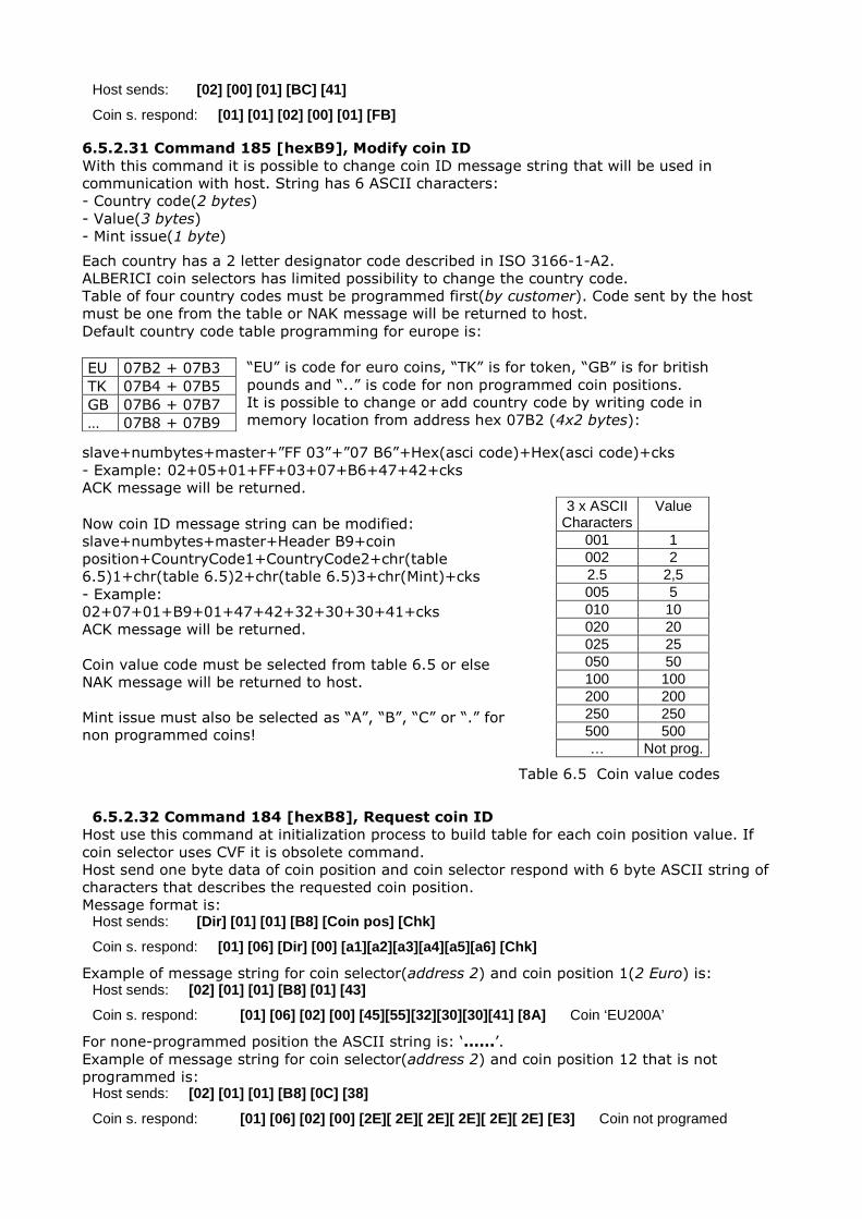
6.5.2.31 Command 185 [hexB9], Modify coin ID
With this command it is possible to change coin ID message string that will be used in
communication with host. String has 6 ASCII characters:
- Country code(2 bytes)
- Value(3 bytes)
- Mint issue(1 byte)
Each country has a 2 letter designator code described in ISO 3166-1-A2.
ALBERICI coin selectors has limited possibility to change the country code.
Table of four country codes must be programmed first(by customer). Code sent by the host
must be one from the table or NAK message will be returned to host.
Default country code table programming for europe is:
EU 07B2 + 07B3
TK 07B4 + 07B5
GB 07B6 + 07B7
… 07B8 + 07B9
“EU” is code for euro coins, “TK” is for token, “GB” is for british
pounds and “..” is code for non programmed coin positions.
It is possible to change or add country code by writing code in
memory location from address hex 07B2 (4x2 bytes):
slave+numbytes+master+”FF 03”+”07 B6”+Hex(asci code)+Hex(asci code)+cks
- Example: 02+05+01+FF+03+07+B6+47+42+cks
ACK message will be returned.
Now coin ID message string can be modified:
slave+numbytes+master+Header B9+coin
position+CountryCode1+CountryCode2+chr(table
6.5)1+chr(table 6.5)2+chr(table 6.5)3+chr(Mint)+cks
- Example:
02+07+01+B9+01+47+42+32+30+30+41+cks
ACK message will be returned.
Coin value code must be selected from table 6.5 or else
NAK message will be returned to host.
Mint issue must also be selected as “A”, “B”, “C” or “.” for
non programmed coins!
3 x ASCII Characters
Value
001 1 002 2 2.5 2,5 005 5 010 10 020 20 025 25 050 50 100 100 200 200 250 250 500 500 … Not prog.
Table 6.5 Coin value codes
6.5.2.32 Command 184 [hexB8], Request coin ID
Host use this command at initialization process to build table for each coin position value. If
coin selector uses CVF it is obsolete command.
Host send one byte data of coin position and coin selector respond with 6 byte ASCII string of
characters that describes the requested coin position.
Message format is: Host sends: [Dir] [01] [01] [B8] [Coin pos] [Chk]
Coin s. respond: [01] [06] [Dir] [00] [a1][a2][a3][a4][a5][a6] [Chk]
Example of message string for coin selector(address 2) and coin position 1(2 Euro) is: Host sends: [02] [01] [01] [B8] [01] [43]
Coin s. respond: [01] [06] [02] [00] [45][55][32][30][30][41] [8A] Coin ‘EU200A’
For none-programmed position the ASCII string is: ‘......’.
Example of message string for coin selector(address 2) and coin position 12 that is not
programmed is: Host sends: [02] [01] [01] [B8] [0C] [38]
Coin s. respond: [01] [06] [02] [00] [2E][ 2E][ 2E][ 2E][ 2E][ 2E] [E3] Coin not programed
6.5.2.33 Command 176 [hexB0], Request alarm counter
Coin selector respond with one bytes of alarm counter data.
Alarm counter is set to zero after power up or reset command. It is incremented each time a
coin acceptor detect any type of erroneous coin acceptance33.
Message format is: Host sends: [Dir] [00] [00] [B0] [Chk]
Coin s. respond: [01] [01] [Dir] [00] [Cunt] [Chk]
Example of message string for coin selector(address 2) after power-up is: Host sends: [02] [00] [01] [B0] [4D]
Coin s. respond: [01] [03] [02] [00] [00] [FC]
6.5.2.34 Command 173 [hexAD], Request thermistor reading
Some coin selectors AL6634 has built in linear temperature sensor.
Using this command is possible to read temperature on surface of coin selector PCB.
If temperature sensor is not built in coin selector will not respond to this command.
Temperature sensor is linear type, with 1 unit change for one degree Celsius change.
For 0°C value will be dec[50], for ie. 25°C it will be dec[75], for -10°C it will be
dec[40] and for 50°C it will be dec[100]. Message format is: Host sends: [Dir] [00] [00] [AD] [Chk]
Coin s. respond: [01] [01] [Dir] [00] [Temp] [Chk]
Example of message string for coin selector(address 2) at ambient temperature
of 25°C is: Host sends: [02] [00] [01] [AD] [50]
Coin s. respond: [01] [01] [02] [00] [4B] [B1]
6.5.2.35 Command 170 [hexAA], Request base year
Coin selector respond with four byte ASCII string of character representing the base year for
calculation of exact date of production. Message format is: Host sends: [Dir] [00] [01] [AA] [Chk]
Coin s. respond: [01] [04] [Dir] [00] [a1][a2][a3][a4] [Chk]
For ALBERICI coin selectors base year is 2000.
Example of message string for coin selector(address 2) is: Host sends: [02] [00] [01] [AA] [53]
Coin s. respond: [01] [04] [02] [00] [32][30][30][30] [37]
6.5.3 MDCES command headers MDCES stands for Multi-Drop Command Extension Set, or so called Multi-drop buss
commands. Multi-drop buss commands gives additional functionality to systems that require
change of address for devices in cctalk network.
Some of commands has different message format than usual cctalk message.
Commands are:
- Address poll
- Address clash
- Address change
- Address random
Because host always use address 1 and address 0 is for broadcast message all commands that
changes the address should not accept this settings.
All changes are stored in non-volatile memory, EEPROM !
33 Alarms: Coin direction error(Jojo), coin to slow(Coin jam ) or coin to fast 34
Coin selectors for use in extreme ambient temperature conditions(external use)
6.5.3.1 Command 253 [hexFD], Address poll
This is a broadcast message used by host to determinate all address of device attached on
cctalk network. Coin selector respond with only one byte (non-standard message format), after
a delay that is proportional to address value multiplied with 4 milliseconds. Message format is: Host sends: [00] [00] [01] [FD] [Chk] Brodcast mesage
Coin s. respond: Dly -> [Address]
Example of message string for coin selector(address 2) is: Host sends: [00] [00] [01] [FD] [02]
Coin s. respond: Dly=8 ms -> [02] Address is 2
Example of message string for coin selector (address 250) is: Host sends: [00] [00] [01] [FD] [02]
Coin s. respond: Dly=1 s -> [FA] Address is 250
6.5.3.2 Command 252 [hexFC], Address clash
Command Address clash has same respond from coin selector but host issue this command
with specific device address. Coin selector respond with only one byte (non-standard message
format), after a random value of time delay to prevent collision if two devices share same
address. Message format is: Host sends: [Dir] [00] [01] [FC] [Chk]
Coin s. respond: Random Dly -> [Address]
Example of message string for coin selector(address 2) AL06V-c is: Host sends: [02] [00] [01] [FC] [01]
Coin s. respond: Random Dly -> [02] Address is 2
6.5.3.3 Command 251 [hexFB], Address change
Command Address change is issued to a specified device only. Coin selector respond with ACK
message. Message format is: Host sends: [Dir] [01] [01] [FB] [Address] [Chk]
Coin s. respond: [01] [00] [02] [00] [FD] ACK
Example of message string for coin selector(address 2) change to address to 20: Host sends: [02] [01] [01] [FB] [14] [ED]
Coin s. respond: [01] [00] [02] [00] [FD] ACK Address is now 20
Coin selector does not respond to attempt of change an address to 0 or 1.
6.5.3.4 Command 250 [hexFA], Address random
Command Address random has the same respond from coin selector. New address is not sent
because each device set its own random address.
Host software sometime can issue this command as broadcast. This will cause change of all
device addresses. Coin selector respond with ACK message. Message format is: Host sends: [Dir] [00] [01] [FA] [Chk]
Coin s. respond: [01] [00] [02] [00] [FD] ACK
Example of message string for coin selector(address 2) is: Host sends: [02] [00] [01] [FA] [03]
Coin s. respond: [01] [00] [02] [00] [FD] ACK Address is changed
Example of broadcast message string for coin selector is: Host sends: [00] [00] [01] [FA] [05] Brodcast mesage
Coin s. respond: [01] [00] [00] [00] [FD] ACK Address is changed
Coin selector has internal mechanism that prevent setting of address 0 or 1!
6.5.4 ALBERICI specific command
First command header for specific factory setting and testing is 255 Factory set-up and test.
This command has several modes of use and some of them are factory secret and are not
explained in this document.
Beside this next chapter describe two modified cctalk commands35 for encrypted exchange of
data between host and coin selector.
6.5.4.1 Command 255, Factory set-up and test
This instruction header is used only for factory testing and programing!
With instruction command header one data byte must be sent for definition of command mode.
Modes are:
- Mode 0(hex 00) No description – reserved for factory use only
- Mode 1(hex 01) No description – reserved for factory use only
- Mode 2(hex 02) Read coin selector memory data
- Mode 3(hex 03) Write coin selector memory data
- Mode 4(hex 04) Analog circuit test
- Mode 5(hex 05) Coin parameter test
- Mode 6(hex 06) Up-grade FLASH(program memory)
- Mode 7(hex 07) Re-initialization
First two modes are only for internal factory use and they are not described in this
document!
To use read and write instruction user must have basic knowledge about coin selectors
memory data organization36!
6.5.4.1.1 Command 255 mode 2, Read coin sel. memory
This instruction sends back to host block of memory data that was requested.
Data memory of coin selector is divided into a 6 group:
- Coin channel data address hex 0600 do 06FF(256 byte-a)
- Input/Output data address hex 0700 do 073F(64 byte-a)
- Factory common data address hex 0740 do 079F(96 byte-a)
- User general data address hex 07A0 do 07E9(74 byte-a)
- Statistic setting address hex 07EA do 07FD(20 byte-a)
- Statistic counters address hex 0800 do 083F(64 byte-a)
Factory key or user PIN protection are some time set to disable the access to some blocks of
memory. Usually all memory is accessible for red instruction.
On any attempt to read memory location that is protected without clearing key or PIN
protection mechanism, coin selector will respond with NAK message.
If number of blocks to read exceed block range, coin selector will also respond with NAK
message. Maximum memory block read of 137 data bytes are limited by coin selector transmit
buffer that has 142 bytes37. If block size extend this number coin selector will respond with
NAK message to. Message string format is: Host sends: [Dir] [04] [01] [FF] [02][Start add-hi][ Start add -lo][ data nr.] [Chk]
Coin s. respond: [01] [n] [Dir] [00] [data 1] [data 2] . . . [data n] [Chk]
Start add-hi is start address hi byte, while start add-lo is address low byte. Data nr. represent
the number of data to read (block size).
Data 1 to data n are requested coin selector memory data.
The example of message string for reading of first coin channel data is: Host sends: [02] [04] [01] [FF][02] [06][ 00] [10] [E2]
Coin s. respond: [01][10][02][00][89][87][B4][77][A7][9F][08][08] [0C][16][0A][04][08][01][09][C8][52] 6.5.4.1.2 Command 255 mode 3, Write coin sel. memory
This command sends block of data to be written in the coin selector RAM memory.
35
Commands 214 Write data block and 215 Read data block 36
Details are available on customer request, see document AL55/66-MemDataOrg-v1.pdf 37 Destination address+Bytes nr.+Source address+Header+59 data+Checksum=142
As for the previous command(read) access to some memory blocks could be protected by
factory key or user PIM mechanisam. Factory common data are usually protected with factory
key and statistic counters and setting with user PIN. Exeption is made for statistic countet
write. Any attempt to write in to statistic counter will erase those couners, thus protecting user
from manipulation with statistics!
Number of bytes sent in command string are representing number of statistic to be erased.
Message string format is: Host sends: [Dir] [n+3] [01] [FF] [03][Start add-hi][ Start add -lo][ data 1]. . . [ data n] [Chk]
Coin s. respond: [01][00] [Dir] [00] [Chk] ACK
The example of message string for programming first output of coin selector AL55/66
(address 2) as pulse parallel output for coin(channel) position 1 is: Host sends: [02] [0B] [01] [FF][03] [07][ 00] [01][00][00][00][ 14][00] [D2]
Coin s. respond: [01][00][02][00] [FD] ACK
The example of message string for erase of all 20 statistic counters38 for coin selector
AL55/66 (address 2) is: Host sends: [02] [04] [01] [FF][02] [08][ 00] [14] [DB]
Coin s. respond: [01][00][02][00] [FD] ACK
User PIN must be sent before erase(write) of statistic counters otherwise coin selector will
respond with NAK message.
Data write will change data in coin selector RAM, and changes will be lost if power
supply turns off! Use write to FLASH command to save changes39!
To save all coin selector RAM data in to FLASH, send write command with no data: Host sends: [02] [01] [01] [FF][03] [FA]
Coin s. respond: [01][00][02][00] [FD] dly 20 -100 ms ->ACK
Coin selector will reply with ACK if write to FLASH was successful.
6.5.4.1.3 Command 255 mode 4, Analog circuit test
This command returns to host string of data that can be used to test analog measuring circuit
state. Details are described in internal documents and not available to users.
6.5.4.1.4 Command 255 mode 5, Coin parameter test
This command returns to host string of data from the last coin measurement.
This data are coin measured parameters and could be used to create and analyze coin data
base. Message string format is: Host sends: [Dir] [01] [01] [FF][05] [Chk]
Coin s. respond: [01] [6] [Dir] [00] [data 1] [data 2] . . . [data 6] [Chk]
Data string description:
- data 1 Measured coin parameter 1, AM1
- data 2 Measured coin parameter 2, PH1
- data 3 Measured coin parameter 3, AM2
- data 4 Measured coin parameter 4, PH2
- data 5 Measured coin parameter 5, PI3
- data 6 Measured coin parameter 6, DIM
The example of message string after insertion of one Euro coin for coin selector AL66 (address
2) is: Host sends: [02] [01] [01] [FF][05] [F8]
Coin s. respond: [01] [6] [02] [00] [8A] [80][8C] [5C] [AB] [8A] [D 0]
Coin measured parameters(data) are available for read till next coin insertion.
This instruction is used by our coin programming software.
6.5.4.1.5 Command 255 mode 6, Up-grade FLASH
This command is used to up-grade coin selector FLASH program memory.
38
20 x 3 byte of memory! 39
Special case write command
User can up-grade coin selector in cases when he knead some new function or improvement,
which where not available at the moment when coin selector was purchased. This instruction is
used by our coin selector programming software and generally is not useful to most users.
Additional information are available on request.
Up-grade files are encrypted in factory and decryption is done internally by monitor
program of coin selector.
Coin selector will accept only correct type of up-grade file!
6.5.4.1.6 Command 255 mode 7, Factory reset
This command will set all coin selector data to initial factory programming values!
Warning: This could lead to unwanted coin selector function if different coin ,
input/output or user setting data where programmed!
The example of message string reset the factory settings is: Host sends: [02] [01] [01] [FF][07] [F6]
Coin s. respond: [01][00][02][00] [FD] ACK
After that, coin selector must be switched off/on!
Ogni possibile cura è stata posta nella redazione del presente manuale. Ciò nonostante, non è possibile garantire in ogni momento la corrispondenza assoluta delle descrizioni, in esso contenute, con le caratteristiche del prodotto.
La Alberici S.p.A. declina ogni e qualsivolglia responsabilità verso l’utilizzatore con riferimento a danni, perdite, o reclami di terze parti, conseguenti all’uso del prodotto o causate da errate interpretazioni del presente manuale.
Alberici S.p.A. si riserva il diritto di modificare, senza avviso, in qualunque modo qualunque parte del presente manuale.
NOTA

®
Progettazione e produzione di sistemi di pagamento, accessori per videogames e macchine vending Design and manufacture of payment systems, accessories for videogames and vending machines
Via Ca’ Bianca 23 40024 Castel San Pietro Terme (BO) – ITALY
Tel. + 39 051 944 300 Fax. + 39 051 944 594
http://www.alberici.net