Embed Size (px)
Citation preview
Amphenol
C 146
Amphenol-Tuchel Electronics GmbH
Steckverb inderSchwereSchwere Steckverb inder
connectorsHeavy dutyHeavy duty connectors

Allgemeine HinweiseDiese Steckverbinder sind in Übereinstimmung mit der Niederspannungs-richtlinie (73/23/EWG) und des Gerätesicherheitsgesetzes entwickelt und gefertigt.Konstruktionsänderungen aufgrund von Qualitätsverbesserungen, Weiterent-wicklungen oder Fertigungserfordernissen behalten wir uns vor.
General informationThese connectors are designed and produced in conformity with the low-voltage directive (73/23/EWG) respectively Gerätesicherheitsgesetz (german law).We reserve the right to change the design due to improvement in quality,development or production requirements.
2 Amphenol
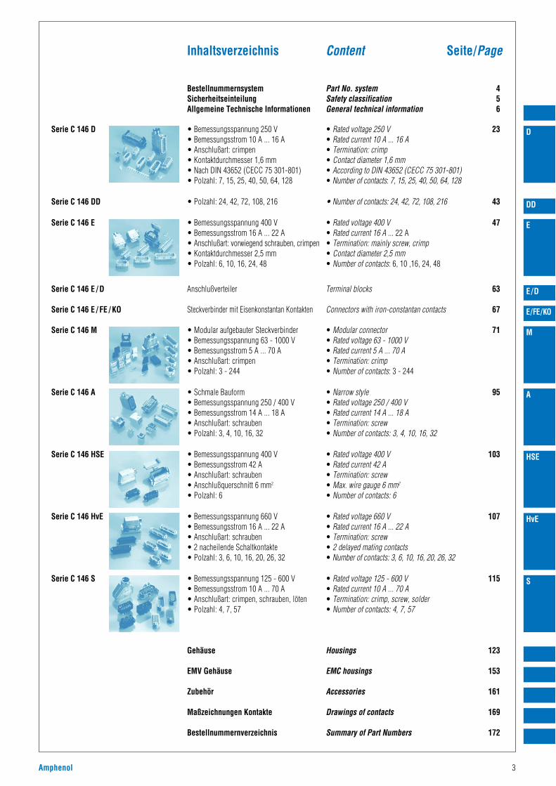
Serie C 146 D
Serie C 146 DD
Serie C 146 E
Serie C 146 E / D
Serie C 146 E / FE / KO
Serie C 146 M
Serie C 146 A
Serie C 146 HSE
Serie C 146 HvE
Serie C 146 S
BestellnummernsystemSicherheitseinteilungAllgemeine Technische Informationen
• Bemessungsspannung 250 V• Bemessungsstrom 10 A ... 16 A• Anschlußart: crimpen• Kontaktdurchmesser 1,6 mm• Nach DIN 43652 (CECC 75 301-801)• Polzahl: 7, 15, 25, 40, 50, 64, 128
• Polzahl: 24, 42, 72, 108, 216
• Bemessungsspannung 400 V• Bemessungsstrom 16 A ... 22 A• Anschlußart: vorwiegend schrauben, crimpen• Kontaktdurchmesser 2,5 mm• Polzahl: 6, 10, 16, 24, 48
Anschlußverteiler
Steckverbinder mit Eisenkonstantan Kontakten
• Modular aufgebauter Steckverbinder• Bemessungsspannung 63 - 1000 V• Bemessungsstrom 5 A ... 70 A• Anschlußart: crimpen• Polzahl: 3 - 244
• Schmale Bauform• Bemessungsspannung 250 / 400 V• Bemessungsstrom 14 A ... 18 A• Anschlußart: schrauben• Polzahl: 3, 4, 10, 16, 32
• Bemessungsspannung 400 V• Bemessungsstrom 42 A• Anschlußart: schrauben• Anschlußquerschnitt 6 mm2
• Polzahl: 6
• Bemessungsspannung 660 V• Bemessungsstrom 16 A ... 22 A• Anschlußart: schrauben• 2 nacheilende Schaltkontakte • Polzahl: 3, 6, 10, 16, 20, 26, 32
• Bemessungsspannung 125 - 600 V• Bemessungsstrom 10 A ... 70 A• Anschlußart: crimpen, schrauben, löten• Polzahl: 4, 7, 57
Gehäuse
EMV Gehäuse
Zubehör
Maßzeichnungen Kontakte
Bestellnummernverzeichnis
Part No. systemSafety classificationGeneral technical information
• Rated voltage 250 V• Rated current 10 A ... 16 A• Termination: crimp• Contact diameter 1,6 mm• According to DIN 43652 (CECC 75 301-801)• Number of contacts: 7, 15, 25, 40, 50, 64, 128
• Number of contacts: 24, 42, 72, 108, 216
• Rated voltage 400 V• Rated current 16 A ... 22 A• Termination: mainly screw, crimp• Contact diameter 2,5 mm• Number of contacts: 6, 10 ,16, 24, 48
Terminal blocks
Connectors with iron-constantan contacts
• Modular connector• Rated voltage 63 - 1000 V• Rated current 5 A ... 70 A• Termination: crimp• Number of contacts: 3 - 244
• Narrow style• Rated voltage 250 / 400 V• Rated current 14 A ... 18 A• Termination: screw• Number of contacts: 3, 4, 10, 16, 32
• Rated voltage 400 V• Rated current 42 A• Termination: screw• Max. wire gauge 6 mm2
• Number of contacts: 6
• Rated voltage 660 V• Rated current 16 A ... 22 A• Termination: screw• 2 delayed mating contacts• Number of contacts: 3, 6, 10, 16, 20, 26, 32
• Rated voltage 125 - 600 V• Rated current 10 A ... 70 A• Termination: crimp, screw, solder• Number of contacts: 4, 7, 57
Housings
EMC housings
Accessories
Drawings of contacts
Summary of Part Numbers
456
23
43
47
63
67
71
95
103
107
115
123
153
161
169
172
Seite/PageInhaltsverzeichnis Content
Amphenol 3
D
DD
E
E/D
E/FE/KO
M
A
HSE
HvE
S
4 Amphenol
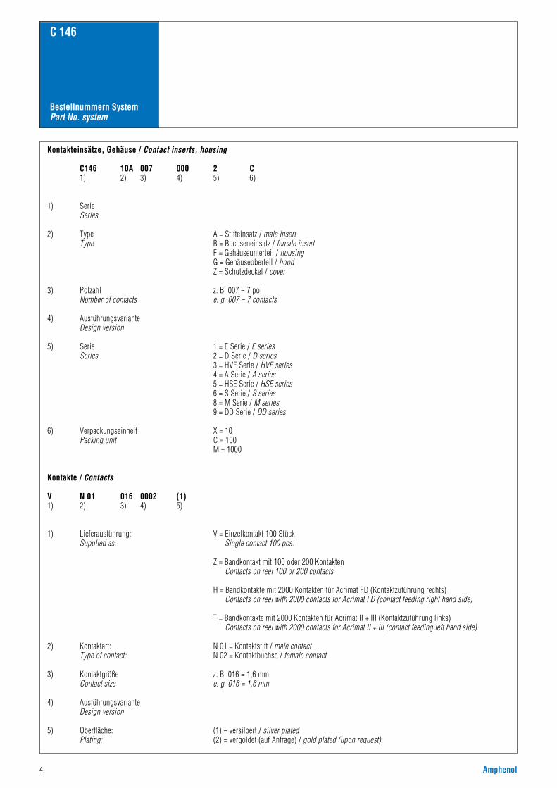
Bestellnummern SystemPart No. system
C 146
Kontakteinsätze, Gehäuse / Contact inserts, housing
C146 10A 007 000 2 C1) 2) 3) 4) 5) 6)
1) SerieSeries
2) Type A = Stifteinsatz / male insertType B = Buchseneinsatz / female insert
F = Gehäuseunterteil / housingG = Gehäuseoberteil / hoodZ = Schutzdeckel / cover
3) Polzahl z. B. 007 = 7 polNumber of contacts e. g. 007 = 7 contacts
4) AusführungsvarianteDesign version
5) Serie 1 = E Serie / E seriesSeries 2 = D Serie / D series
3 = HVE Serie / HVE series4 = A Serie / A series5 = HSE Serie / HSE series6 = S Serie / S series8 = M Serie / M series9 = DD Serie / DD series
6) Verpackungseinheit X = 10Packing unit C = 100
M = 1000
Kontakte / Contacts
V N 01 016 0002 (1)1) 2) 3) 4) 5)
1) Lieferausführung: V = Einzelkontakt 100 StückSupplied as: Single contact 100 pcs.
Z = Bandkontakt mit 100 oder 200 KontaktenContacts on reel 100 or 200 contacts
H = Bandkontakte mit 2000 Kontakten für Acrimat FD (Kontaktzuführung rechts)Contacts on reel with 2000 contacts for Acrimat FD (contact feeding right hand side)
T = Bandkontakte mit 2000 Kontakten für Acrimat II + III (Kontaktzuführung links)Contacts on reel with 2000 contacts for Acrimat II + III (contact feeding left hand side)
2) Kontaktart: N 01 = Kontaktstift / male contactType of contact: N 02 = Kontaktbuchse / female contact
3) Kontaktgröße z. B. 016 = 1,6 mmContact size e. g. 016 = 1,6 mm
4) AusführungsvarianteDesign version
5) Oberfläche: (1) = versilbert / silver platedPlating: (2) = vergoldet (auf Anfrage) / gold plated (upon request)
Amphenol 5
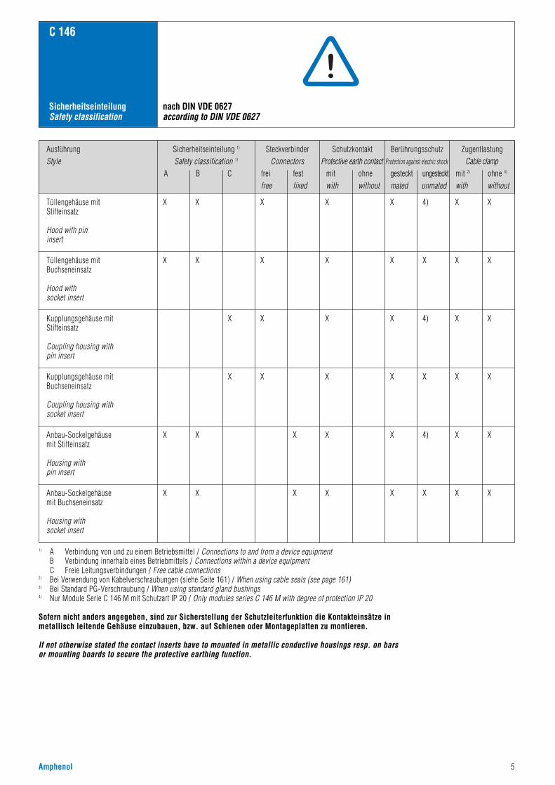
AusführungStyle
Sicherheitseinteilung 1)
Safety classification 1)
A B C
SteckverbinderConnectors
frei festfree fixed
SchutzkontaktProtective earth contact
mit ohnewith without
ZugentlastungCable clamp
mit 2) ohne 3)
with without
BerührungsschutzProtection against electric shock
gesteckt ungestecktmated unmated
C 146
SicherheitseinteilungSafety classification
nach DIN VDE 0627according to DIN VDE 0627
Tüllengehäuse mitStifteinsatz
Hood with pininsert
X X X X X 4) X X
X X X X X X X X
X X X X 4) X X
X X X X X X X
X X X X X 4) X X
X X X X X X X X
Tüllengehäuse mitBuchseneinsatz
Hood withsocket insert
Kupplungsgehäuse mitStifteinsatz
Coupling housing withpin insert
Kupplungsgehäuse mitBuchseneinsatz
Coupling housing withsocket insert
Anbau-Sockelgehäusemit Stifteinsatz
Housing withpin insert
Anbau-Sockelgehäusemit Buchseneinsatz
Housing withsocket insert
1) A Verbindung von und zu einem Betriebsmittel / Connections to and from a device equipmentB Verbindung innerhalb eines Betriebmittels / Connections within a device equipmentC Freie Leitungsverbindungen / Free cable connections
2) Bei Verwendung von Kabelverschraubungen (siehe Seite 161) / When using cable seals (see page 161)3) Bei Standard PG-Verschraubung / When using standard gland bushings4) Nur Module Serie C 146 M mit Schutzart IP 20 / Only modules series C 146 M with degree of protection IP 20
Sofern nicht anders angegeben, sind zur Sicherstellung der Schutzleiterfunktion die Kontakteinsätze in metallisch leitende Gehäuse einzubauen, bzw. auf Schienen oder Montageplatten zu montieren.
If not otherwise stated the contact inserts have to mounted in metallic conductive housings resp. on barsor mounting boards to secure the protective earthing function.
6 Amphenol
C 146
Technische InformationenTechnical information
Allgemeine technische Informationen
Hinweise:• Verbindlich für den Einsatz von Steckverbindern und Steckvor-
richtungen sind die jeweiligen Anforderungen der Gerätevorschriften.Dies gilt insbesondere für die Festlegung der Bemessungsspannungund der damit zusammenhängenden Luft- und Kriechstrecken.
• Alle Angaben der Bemessungsdaten der in diesemKatalog aufgeführten Steckverbindern sind auf die Überspannungs-kategorie III sowie den Verschmutzungsgrad 3 (Anwendung imMaschinenbau) bezogen.
• Alle technischen Angaben beziehen sich auf Steckverbinder, alsoBetriebsmittel, die bei bestimmungsgemäßer Verwendung (unterelektrischer Spannung) nicht gesteckt oder getrennt werden dürfen.Soweit Steckverbinder im Sinne von Steckvorrichtungen verwendetwerden, ist dies in den betreffenden Abschnitten aufgeführt.
• Der Berührungsschutz der Kontakteinsätze im Anschlußbereich istdurch den Einbau sicherzustellen.
• Ein ausführliches Kompendium von Steckverbinder-Begriffen befindetsich am Ende dieses Kapitels.
• Nachstehend aufgeführte Auszüge aus Normen dienen der allgemeinenInformation. Im konkreten Anwendungsfall sind die jeweils gültigenNormen anzuwenden. Die IEC 60664 entspricht DIN VDE 0110.
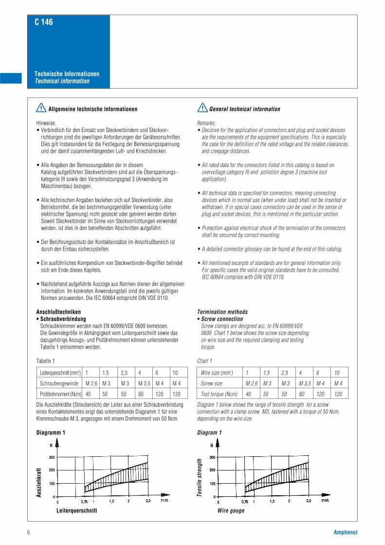
Anschlußtechniken• Schraubverbindung
Schraubklemmen werden nach EN 60999/VDE 0609 bemessen. Die Gewindegröße in Abhängigkeit vom Leiterquerschnitt sowie dasdazugehörige Anzugs- und Prüfdrehmoment können untenstehenderTabelle 1 entnommen werden.
Tabelle 1
Die Ausziehkräfte (Streubereich) der Leiter aus einer Schraubverbindungeines Kontaktelementes zeigt das untenstehende Diagramm 1 für eineKlemmschraube M 3, angezogen mit einem Drehmoment von 50 Ncm.
Diagramm 1
General technical information
Remarks:• Decisive for the application of connectors and plug and socket devices
are the requirements of the equipment specifications. This is especiallythe case for the definition of the rated voltage and the related clearancesand creepage distances.
• All rated data for the connectors listed in this catalog is based onovervoltage category III and pollution degree 3 (machine toolapplication).
• All technical data is specified for connectors, meaning connectingdevices which in normal use (when under load) shall not be inserted orwithdrawn. If in special cases connectors can be used in the sense ofplug and socket devices, this is mentioned in the particular section.
• Protection against electrical shock of the termination of the connectorsshall be securred by correct mounting.
• A detailed connector glossary can be found at the end of this catalog.
• All mentioned excerpts of standards are for general information only.For specific cases the valid original standards have to be consulted.IEC 60664 complies with DIN VDE 0110.
Termination methods• Screw connection
Screw clamps are designed acc. to EN 60999/VDE0609. Chart 1 below shows the screw size dependingon wire size and the required clamping and testingtorque.
Chart 1
Diagram 1 below shows the range of tensile strength for a screwconnection with a clamp screw M3, fastened with a torque of 50 Ncm,depending on the wire size.
Diagram 1
Wire size (mm2) 1 1,5 2,5 4 6 10
Screw size M 2,6 M 3 M 3 M 3,5 M 4 M 4
Test torque (Ncm) 40 50 50 80 120 120
Leiterquerschnitt (mm2) 1 1,5 2,5 4 6 10
Schraubengewinde M 2,6 M 3 M 3 M 3,5 M 4 M 4
Prüfdrehmoment (Ncm) 40 50 50 80 120 120
Tens
ile s
tren
gth
Wire gauge
Ausz
iehk
raft
Leiterquerschnitt
Amphenol 7
C 146
Technische InformationenTechnical information
A
B
1000
500400
300
200
100
5040
30
20
10
50,05 0,1 0,2 0,5 1,0 1,5 2,5 4,0 6,0 10,0
N
4000
3000
2000
1000
500 400
300
200
100
50 40
30
20
lb
28 26 24 22 20 18 16 14 12 10 8AWGmm
Min
dest
zugf
estig
keit
in N
/ M
in. t
ensi
le s
tren
ght (
N)
Leiterquerschnitt in mm / Wire gauge in mm
• CrimpverbindungEine Crimpverbindung ist eine nicht lösbare elektrische Verbindungzwischen einem Leiter und einem Crimpkontakt mit Hilfe derCrimptechnik. Durch genau auf Crimphülse und Leiterquerschnittabgestimmte Crimpprofile werden durch Druck und gezielte Verformungzuverlässige elektrische Verbindungen hergestellt. Es gibt offeneCrimphülsen (gestanzte Kontakte) und geschlossene Crimphülsen(gedrehte Kontakte).
Die wesentlichen Vorteile von Crimpverbindungen sind:• Rationelle Verarbeitung der Kontakte• Konstante elektrische und mechanische Werte durch gleichbleibende
Crimpqualität.(Eine ausführliche Beschreibung der Crimptechnologie findenSie in unserem Katalog „Werkzeuge“.)
Die Anforderungen an Crimpverbindungen sind in der DIN IEC 60352,Teil 2, festgelegt.
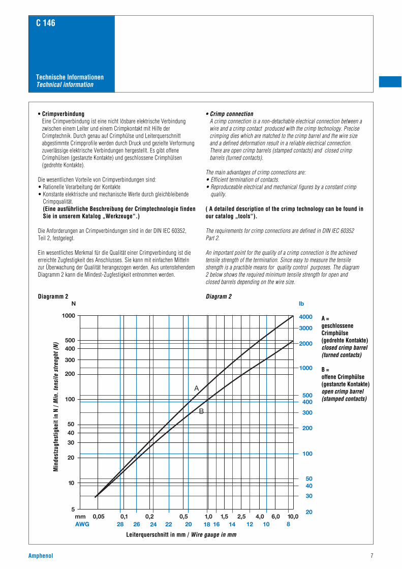
Ein wesentliches Merkmal für die Qualität einer Crimpverbindung ist dieerreichte Zugfestigkeit des Anschlusses. Sie kann mit einfachen Mittelnzur Überwachung der Qualität herangezogen werden. Aus untenstehendemDiagramm 2 kann die Mindest-Zugfestigkeit entnommen werden.
Diagramm 2
• Crimp connectionA crimp connection is a non-detachable electrical connection between awire and a crimp contact produced with the crimp technology. Precisecrimping dies which are matched to the crimp barrel and the wire sizeand a defined deformation result in a reliable electrical connection.There are open crimp barrels (stamped contacts) and closed crimpbarrels (turned contacts).
The main advantages of crimp connections are:• Efficient termination of contacts.• Reproduceable electrical and mechanical figures by a constant crimp
quality.
( A detailed description of the crimp technology can be found inour catalog „tools“).
The requirements for crimp connections are defined in DIN IEC 60352Part 2.
An important point for the quality of a crimp connection is the achievedtensile strength of the termination. Since easy to measure the tensilestrength is a practible means for quality control purposes. The diagram2 below shows the required minimum tensile strength for open andclosed barrels depending on the wire size.
Diagram 2
A = geschlosseneCrimphülse(gedrehte Kontakte)closed crimp barrel(turned contacts)
B = offene Crimphülse(gestanzte Kontakte)open crimp barrel(stamped contacts)
AWG Wire composition
C 146
Technische InformationenTechnical information
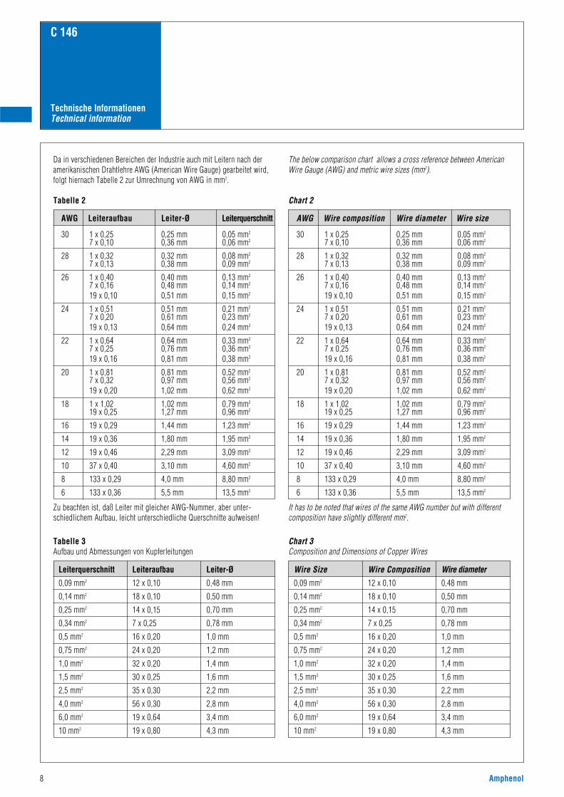
Da in verschiedenen Bereichen der Industrie auch mit Leitern nach deramerikanischen Drahtlehre AWG (American Wire Gauge) gearbeitet wird,folgt hiernach Tabelle 2 zur Umrechnung von AWG in mm2.
Tabelle 2
Zu beachten ist, daß Leiter mit gleicher AWG-Nummer, aber unter-schiedlichem Aufbau, leicht unterschiedliche Querschnitte aufweisen!
The below comparison chart allows a cross reference between AmericanWire Gauge (AWG) and metric wire sizes (mm2).
Chart 2
It has to be noted that wires of the same AWG number but with differentcomposition have slightly different mm2.
AWG Leiteraufbau Leiter-Ø Leiterquerschnitt
30 1 x 0,25 0,25 mm 0,05 mm2
7 x 0,10 0,36 mm 0,06 mm2
28 1 x 0,32 0,32 mm 0,08 mm2
7 x 0,13 0,38 mm 0,09 mm2
26 1 x 0,40 0,40 mm 0,13 mm2
7 x 0,16 0,48 mm 0,14 mm2
19 x 0,10 0,51 mm 0,15 mm2
24 1 x 0,51 0,51 mm 0,21 mm2
7 x 0,20 0,61 mm 0,23 mm2
19 x 0,13 0,64 mm 0,24 mm2
22 1 x 0,64 0,64 mm 0,33 mm2
7 x 0,25 0,76 mm 0,36 mm2
19 x 0,16 0,81 mm 0,38 mm2
20 1 x 0,81 0,81 mm 0,52 mm2
7 x 0,32 0,97 mm 0,56 mm2
19 x 0,20 1,02 mm 0,62 mm2
18 1 x 1,02 1,02 mm 0,79 mm2
19 x 0,25 1,27 mm 0,96 mm2
16 19 x 0,29 1,44 mm 1,23 mm2
14 19 x 0,36 1,80 mm 1,95 mm2
12 19 x 0,46 2,29 mm 3,09 mm2
10 37 x 0,40 3,10 mm 4,60 mm2
8 133 x 0,29 4,0 mm 8,80 mm2
6 133 x 0,36 5,5 mm 13,5 mm2
Tabelle 3Aufbau und Abmessungen von Kupferleitungen
Chart 3Composition and Dimensions of Copper Wires
Leiterquerschnitt Leiteraufbau Leiter-Ø
0,09 mm2 12 x 0,10 0,48 mm
0,14 mm2 18 x 0,10 0,50 mm
0,25 mm2 14 x 0,15 0,70 mm
0,34 mm2 7 x 0,25 0,78 mm
0,5 mm2 16 x 0,20 1,0 mm
0,75 mm2 24 x 0,20 1,2 mm
1,0 mm2 32 x 0,20 1,4 mm
1,5 mm2 30 x 0,25 1,6 mm
2,5 mm2 35 x 0,30 2,2 mm
4,0 mm2 56 x 0,30 2,8 mm
6,0 mm2 19 x 0,64 3,4 mm
10 mm2 19 x 0,80 4,3 mm
Wire diameter Wire size
Wire Size Wire Composition Wire diameter
0,09 mm2 12 x 0,10 0,48 mm
0,14 mm2 18 x 0,10 0,50 mm
0,25 mm2 14 x 0,15 0,70 mm
0,34 mm2 7 x 0,25 0,78 mm
0,5 mm2 16 x 0,20 1,0 mm
0,75 mm2 24 x 0,20 1,2 mm
1,0 mm2 32 x 0,20 1,4 mm
1,5 mm2 30 x 0,25 1,6 mm
2,5 mm2 35 x 0,30 2,2 mm
4,0 mm2 56 x 0,30 2,8 mm
6,0 mm2 19 x 0,64 3,4 mm
10 mm2 19 x 0,80 4,3 mm
8 Amphenol
Amphenol 9
C 146
Technische InformationenTechnical information
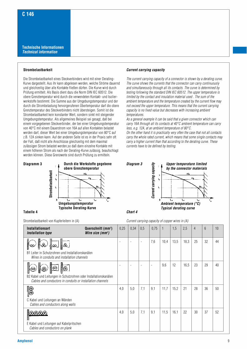
Strombelastbarkeit
Die Strombelastbarkeit eines Steckverbinders wird mit einer Derating-Kurve dargestellt. Aus ihr kann abgelesen werden, welche Ströme dauerndund gleichzeitig über alle Kontakte fließen dürfen. Die Kurve wird durchPrüfung ermittelt. Als Basis dient dazu die Norm DIN IEC 60512. Dieobere Grenztemperatur wird durch die verwendeten Kontakt- und Isolier-werkstoffe bestimmt. Die Summe aus der Umgebungstemperatur und derdurch die Strombelastung hervorgerufenen Übertemperatur darf die obereGrenztemperatur des Steckverbinders nicht übersteigen. Somit ist dieStrombelastbarkeit kein konstanter Wert, sondern sinkt mit steigenderUmgebungstemperatur. Als allgemeines Beispiel sei gesagt, daß beieinem vorgegebenen Steckverbinder, der bei einer Umgebungstemperaturvon 40°C mit einem Dauerstrom von 16A auf allen Kontakten belastetwerden darf, dieser Wert bei einer Umgebungstemperatur von 80°C aufz.B. 12A sinken kann. Auf der anderen Seite ist es in der Praxis sehr oftder Fall, daß nicht alle Anschlüsse gleichzeitig mit dem maximalzulässigen Strom belastet werden,so daß dann einzelne Kontakte miteinem höheren Strom als nach der Derating-Kurve zulässig, beaufschlagtwerden können. Diese Grenzwerte sind durch Prüfung zu ermitteln.
Diagramm 3
Current carrying capacity
The current carrying capacity of a connector is shown by a derating curve.The curve shows the currents that the connector can carry continuouslyand simultaneously through all its contacts. The curve is determined bytesting following the standard DIN IEC 60512. The upper temperature islimited by the contact and insulation material used . The sum of theambient temperature and the temperature created by the current flow maynot exceed the upper temperature. This means that the current carryingcapacity is no fixed value but decreases with increasing ambienttemperatures.As a general example it can be said that a given connector which cancarry 16A through all its contacts at 40°C ambient temperature can carryless, e.g. 12A, at an ambient temperature of 80°C.On the other hand it is practically very often the case that not all contactscarry the whole rated current, which means that some single contacts maycarry a higher current than that according to the derating curve. Thesecurrents have to be defined by testing.
Diagram 3
Tabelle 4
Strombelastbarkeit von Kupferleitern in (A)
Chart 4
Current carrying capacity of copper wires in (A)
- - - 7,6 10,4 13,5 18,3 25 32 44
- - - - 9,6 12 16,5 23 29 40
4,0 5,0 7,1 9,1 11,7 15,2 21 28 36 50
4,0 5,0 7,1 9,1 11,5 16,1 22 30 37 52
B1 Leiter in Schutzrohren und InstallationskanälenWires in conduits and installation channels
B2 Kabel und Leitungen in Schutzrohren oder InstallationskanälenCables and conductors in conduits or installation channels
C Kabel und Leitungen an WändenCables and conductors along walls
E Kabel und Leitungen auf KabelpritschenCables and conductors on plank
Installationsart Querschnitt (mm2) 0,25 0,34 0,5 0,75 1 1,5 2,5 4 6 10Installation type Wire size (mm2)
Stro
mbe
last
bark
eit
UmgebungstemperaturTypische Derating-Kurve
Durch die Werkstoffe gegebeneobere Grenztemperatur
Curr
ent c
arry
ing
capa
city
Ambient temperature (°C)Typical derating curve
Upper temperature limited by the connector materials
Ambient temperature (°C) Correction value
30 1,15
35 1,03
40 1,00
45 0,91
50 0,82
55 0,71
60 0,58
C 146
Technische InformationenTechnical information
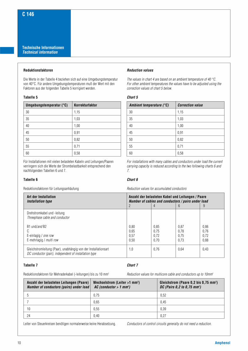
Reduktionsfaktoren
Die Werte in der Tabelle 4 beziehen sich auf eine Umgebungstemperaturvon 40°C. Für andere Umgebungstemperaturen muß der Wert mit denFaktoren aus der folgenden Tabelle 5 korrigiert werden.
Tabelle 5
Reduction values
The values in chart 4 are based on an ambient temperature of 40 °C. For other ambient temperatures the values have to be adjusted using thecorrection values of chart 5 below.
Chart 5
Umgebungstemperatur (°C) Korrekturfaktor
30 1,15
35 1,03
40 1,00
45 0,91
50 0,82
55 0,71
60 0,58
Für Installationen mit vielen belasteten Kabeln und Leitungen/Paarenverringern sich die Werte der Strombelastbarkeit entsprechend dennachfolgenden Tabellen 6 und 7.
Tabelle 6
Reduktionsfaktoren für Leitungsanhäufung
Tabelle 7
Reduktionsfaktoren für Mehraderkabel (-leitungen) bis zu 10 mm2
Leiter von Steuerkreisen benötigen normalerweise keine Herabsetzung.
For installations with many cables and conductors under load the currentcarrying capacity is reduced according to the two following charts 6 and7.
Chart 6
Reduction values for accumulated conductors
Chart 7
Reduction values for multicore cable and conductors up to 10mm2
Conductors of control circuits generally do not need a reduction.
Art der Installation Anzahl der belasteten Kabel und Leitungen / PaareInstallation type Number of cables and conductors / pairs under load
2 4 6 9
Drehstromkabel und -leitungThreephase cable and conductor
B1 und/and B2CE-einlagig / one rowE-mehrlagig / multi row
Gleichstromleitung (Paar), unabhängig von der InstallationsartDC conductor (pair), independent of installation type
0,80 0,85 0,87 0,860,65 0,75 0,78 0,760,57 0,72 0,75 0,720,50 0,70 0,73 0,88
1,0 0,76 0,64 0,43
Anzahl der belasteten Leitungen (Paare) Wechselstrom (Leiter >1 mm2) Gleichstrom (Paare 0,2 bis 0,75 mm2)Number of conductors (pairs) under load AC (conductor > 1 mm2) DC (Pairs 0,2 to 0,75 mm2)
5 0,75 0,52
7 0,65 0,45
10 0,55 0,39
24 0,40 0,27
10 Amphenol
Amphenol 11
C 146
Technische InformationenTechnical information
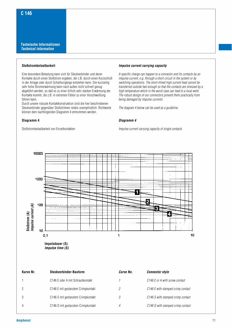
Stoßstrombelastbarkeit
Eine besondere Belastung kann sich für Steckverbinder und derenKontakte durch einen Stoßstrom ergeben, der z.B. durch einen Kurzschlußin der Anlage oder durch Schaltvorgänge entstehen kann. Die kurzzeitigsehr hohe Stromerwärmung kann nach außen nicht schnell genugabgeführt werden, so daß es zu einer örtlich sehr starken Erwärmung derKontakte kommt, die z.B. in extremen Fällen zu einer Verschweißungführen kann.Durch unsere robuste Kontaktkonstruktion sind die hier beschriebenenSteckverbinder gegenüber Stoßströmen relativ unempfindlich. Richtwertekönnen dem nachfolgenden Diagramm 4 entnommen werden.
Diagramm 4
Stoßstrombelastbarkeit von Einzelkontakten
Kurve Nr. Steckverbinder-Bauform
1 C146 E oder A mit Schraubkontakt
2 C146 E mit gestanztem Crimpkontakt
3 C146 S mit gestanztem Crimpkontakt
4 C146 D mit gestanztem Crimpkontakt
Impulse current carrying capacity
A specific charge can happen to a connector and its contacts by animpulse current, e.g. through a short circuit in the system or by switching operations. The short-timed high current heat cannot betransferred outside fast enough so that the contacts are stressed by a high temperature which in the worst case can lead to a local weld.The robust design of our connectors prevent them practically from being damaged by impulse currents.
The diagram 4 below can be used as a guideline.
Diagramm 4
Impulse current carrying capacity of single contacts
Curve No. Connector style
1 C146 E or A with screw contact
2 C146 E with stamped crimp contact
3 C146 S with stamped crimp contact
4 C146 D with stamped crimp contact
Stoß
stro
m (A
)Im
puls
e cu
rren
t (A)
Impulsdauer (S)Impulse time (S)
C 146
Technische InformationenTechnical information
Spannungseinstufung der Steckverbinder
Allgemeines
Zur Spannungseinstufung von Steckverbindern werden die Luft- undKriechstrecken herangezogen. Die Beurteilung und Bemessung der Luft-und Kriechstrecken hat sich durch die Einführung derIsolationskoordination geändert.
Es gelten dafür die folgenden Normen:
IEC 60664-1/10.92Insulation coordination for equipment within low-voltage systems
DIN VDE 0110/4.97Isolationskoordination für elektrischeBetriebsmittel in Niederspannungsanlagen
Isolationskoordination umfaßt die Auswahl der elektrischen Isolations-eigenschaften eines Betriebsmittels hinsichtlich dessen Anwendung undin Bezug auf seine Umgebung.
LuftstreckenDie Luftstrecke ist die kürzeste Entfernung in Luft zwischen zwei leitendenTeilen. Ein wichtiger Punkt bei der Bemessung von Luftstrecken ist zu-nächst die Festlegung der Überspannungskategorie. Die Norm hat diemöglichen Überspannungen in die nachstehenden vier Kategorien ein-geteilt:
Überspannungskategorie IBetriebsmittel, die zur Anwendung in Geräten oder Teilen von Anlagenbestimmt sind, in denen keine Überspannungen auftreten können. Hier-unter fallen Geräte, die vorwiegend mit Kleinspannungen betriebenwerden.
Überspannungskategorie IIBetriebsmittel, die zur Anwendung in Anlagen oder Teilen von diesenbestimmt sind, in denen Blitzüberspannungen nicht berücksichtigt werdenmüssen, aber wohl Überspannungen durch Schaltvorgänge.Hierunter fallen z.B. elektrische Haushaltsgeräte.
Überspannungskategorie IIIBetriebsmittel, die zur Anwendung in Anlagen oder Teilen von diesenbestimmt sind, bei denen Blitzüberspannungen nicht berücksichtigtwerden müssen, wohl aber Überspannungen durch Schaltvorgänge und andie im Hinblick auf die Sicherheit und Verfügbarkeit des Betriebsmittelsoder von davon abhängigen Netzen besondere Anforderungen gestelltwerden.Hierunter fallen Betriebsmittel für feste Installationen, z.B.Schutzeinrichtungen, Schütze, Schalter und Steckdosen.
Überspannungskategorie IVBetriebsmittel, die zur Anwendung in Anlagen oder Teilen von diesenbestimmt sind, bei denen Blitzüberspannungen zu berücksichtigen sind.Hierunter fallen Betriebsmittel zum Anschluß an Freileitungen, z.B.Rundsteuerempfänger, Zähler.
Voltage grading of connectors
General
Clearances and creepage distances are the base for voltage grading ofconnectors. Valuation and dimensioning of clearances and creepagedistances have changed since the introduction of insulation coordination.
The following standards apply for this:
IEC 60664-1/10.92Insulation coordination for equipment withinlow-voltage systems
DIN VDE 0110/4.97Isolationskoordination für elektrische Betriebsmittel in Niederspannungsanlagen
Insulation coordination comprises the selection of the electrical insulationperformances of an equipment taking into account the expected use andits environment.
ClearancesThe clearance is the shortest distance in air between two conductive parts.An important point for the dimensioning of clearances is firstly thedetermination of the overvoltage category. The above standard specifiesthe possible overvoltages into the four following categories:
Overvoltage category IEquipment intended for the use in appliances or parts of installations inwhich no overvoltage can occur.Examples are low-voltage equipments.
Overvoltage category IIEquipment intended for the use in installations or parts of it in whichlightning overvoltages do not need to be considered, however switchingovervoltages generated by the equipment.Examples are household appliances.
Overvoltage category IIIEquipment intended for the use in installtions or parts of it in whichlightning overvoltages do not need to be considered, however switchingovervoltages generated by the euipment, and for cases where thereliability and the availability of the equipment or its dependent circuitsare subject to special requirements.Examples are protecting means, switches and sockets.
Overvoltage category IVEquipment intended for the use in installations or parts of it in whichlightning overvoltage has to be considered. Examples are electricity meters, overcurrent protection switches.
12 Amphenol
Amphenol 13
C 146
Technische InformationenTechnical information
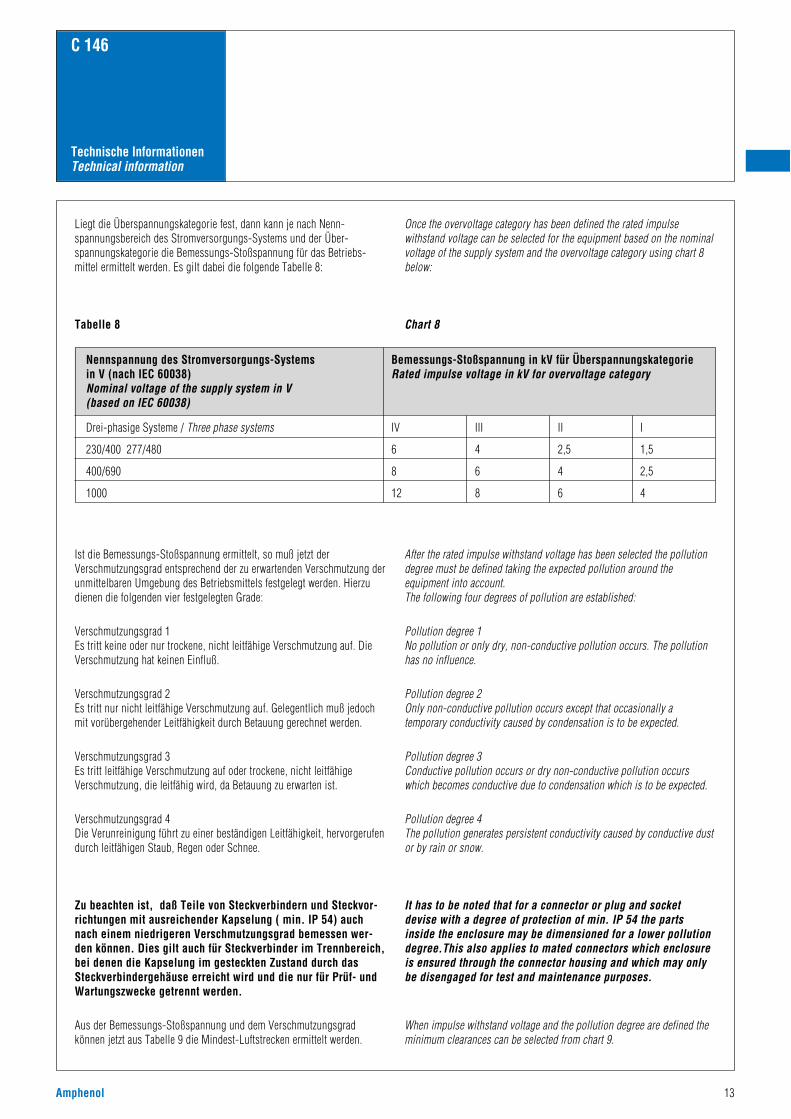
Liegt die Überspannungskategorie fest, dann kann je nach Nenn-spannungsbereich des Stromversorgungs-Systems und der Über-spannungskategorie die Bemessungs-Stoßspannung für das Betriebs-mittel ermittelt werden. Es gilt dabei die folgende Tabelle 8:
Tabelle 8
Ist die Bemessungs-Stoßspannung ermittelt, so muß jetzt derVerschmutzungsgrad entsprechend der zu erwartenden Verschmutzung derunmittelbaren Umgebung des Betriebsmittels festgelegt werden. Hierzudienen die folgenden vier festgelegten Grade:
Verschmutzungsgrad 1Es tritt keine oder nur trockene, nicht leitfähige Verschmutzung auf. DieVerschmutzung hat keinen Einfluß.
Verschmutzungsgrad 2Es tritt nur nicht leitfähige Verschmutzung auf. Gelegentlich muß jedochmit vorübergehender Leitfähigkeit durch Betauung gerechnet werden.
Verschmutzungsgrad 3Es tritt leitfähige Verschmutzung auf oder trockene, nicht leitfähigeVerschmutzung, die leitfähig wird, da Betauung zu erwarten ist.
Verschmutzungsgrad 4Die Verunreinigung führt zu einer beständigen Leitfähigkeit, hervorgerufendurch leitfähigen Staub, Regen oder Schnee.
Zu beachten ist, daß Teile von Steckverbindern und Steckvor-richtungen mit ausreichender Kapselung ( min. IP 54) auchnach einem niedrigeren Verschmutzungsgrad bemessen wer-den können. Dies gilt auch für Steckverbinder im Trennbereich,bei denen die Kapselung im gesteckten Zustand durch dasSteckverbindergehäuse erreicht wird und die nur für Prüf- undWartungszwecke getrennt werden.
Aus der Bemessungs-Stoßspannung und dem Verschmutzungsgradkönnen jetzt aus Tabelle 9 die Mindest-Luftstrecken ermittelt werden.
Once the overvoltage category has been defined the rated impulsewithstand voltage can be selected for the equipment based on the nominalvoltage of the supply system and the overvoltage category using chart 8below:
Chart 8
After the rated impulse withstand voltage has been selected the pollutiondegree must be defined taking the expected pollution around theequipment into account.The following four degrees of pollution are established:
Pollution degree 1No pollution or only dry, non-conductive pollution occurs. The pollutionhas no influence.
Pollution degree 2Only non-conductive pollution occurs except that occasionally atemporary conductivity caused by condensation is to be expected.
Pollution degree 3Conductive pollution occurs or dry non-conductive pollution occurswhich becomes conductive due to condensation which is to be expected.
Pollution degree 4The pollution generates persistent conductivity caused by conductive dustor by rain or snow.
It has to be noted that for a connector or plug and socketdevise with a degree of protection of min. IP 54 the partsinside the enclosure may be dimensioned for a lower pollutiondegree.This also applies to mated connectors which enclosureis ensured through the connector housing and which may onlybe disengaged for test and maintenance purposes.
When impulse withstand voltage and the pollution degree are defined theminimum clearances can be selected from chart 9.
Nennspannung des Stromversorgungs-Systems in V (nach IEC 60038)Nominal voltage of the supply system in V(based on IEC 60038)
Bemessungs-Stoßspannung in kV für ÜberspannungskategorieRated impulse voltage in kV for overvoltage category
Drei-phasige Systeme / Three phase systems IV III II I
230/400 277/480 6 4 2,5 1,5
400/690 8 6 4 2,5
1000 12 8 6 4
C 146
Technische InformationenTechnical information
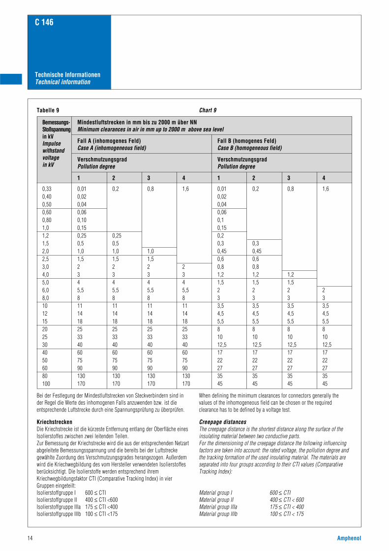
Tabelle 9
Bemessungs-Stoßspannungin kVImpulsewithstandvoltagein kV
0,330,400,500,600,801,01,21,52,02,53,04,05,06,08,010121520253040506080100
0,010,020,040,060,100,150,250,51,01,52345,58111418253340607590130170
0,2
0,250,51,01,52345,58111418253340607590130170
0,8
1,01,52345,58111418253340607590130170
1,6
2345,58111418253340607590130170
0,010,020,040,060,10,150,20,30,450,60,81,21,5233,54,55,581012,51722273545
0,2
0,30,450,60,81,21,5233,54,55,581012,51722273545
0,8
1,21,5233,54,55,581012,51722273545
1,6
233,54,55,581012,51722273545
Mindestluftstrecken in mm bis zu 2000 m über NNMinimum clearances in air in mm up to 2000 m above sea level
Fall A (inhomogenes Feld)Case A (inhomogeneous field)
VerschmutzungsgradPollution degree
1 2 3 4 1 2 3 4
Fall B (homogenes Feld)Case B (homogeneous field)
VerschmutzungsgradPollution degree
Chart 9
Creepage distancesThe creepage distance is the shortest distance along the surface of theinsulating material between two conductive parts.For the dimensioning of the creepage distance the following influencingfactors are taken into account: the rated voltage, the pollution degree andthe tracking formation of the used insulating material. The materials areseparated into four groups according to their CTI values (ComparativeTracking Index):
Material group I 600 ≤ CTIMaterial group II 400 ≤ CTI < 600Material group IIIa 175 ≤ CTI < 400Material group IIIb 100 ≤ CTI < 175
KriechstreckenDie Kriechstrecke ist die kürzeste Entfernung entlang der Oberfläche einesIsolierstoffes zwischen zwei leitenden Teilen.Zur Bemessung der Kriechstrecke wird die aus der entsprechenden Netzartabgeleitete Bemessungsspannung und die bereits bei der Luftstreckegewählte Zuordung des Verschmutzungsgrades herangezogen. Außerdemwird die Kriechwegbildung des vom Hersteller verwendeten Isolierstoffesberücksichtigt. Die Isolierstoffe werden entsprechend ihremKriechwegbildungsfaktor CTI (Comparative Tracking Index) in vierGruppen eingeteilt:Isolierstoffgruppe I 600 ≤ CTIIsolierstoffgruppe II 400 ≤ CTI <600Isolierstoffgruppe IIIa 175 ≤ CTI <400Isolierstoffgruppe IIIb 100 ≤ CTI <175
Bei der Festlegung der Mindestluftstrecken von Steckverbindern sind inder Regel die Werte des inhomogenen Falls anzuwenden bzw. ist dieentsprechende Luftstrecke durch eine Spannungsprüfung zu überprüfen.
When defining the minimum clearances for connectors generally thevalues of the inhomogeneous field can be chosen or the requiredclearance has to be defined by a voltage test.
14 Amphenol
Amphenol 15
C 146
Technische InformationenTechnical information
Bemes-sungs-spannungU-effRatedvoltageU in V
1012,51620253240506380100125160200250320400500630800100012501600200025003200400050006300800010000
0,0250,0250,0250,0250,0250,0250,0250,0250,040,0630,10,160,250,40,560,7511,31,82,43,2
0,040,040,040,040,040,040,040,040,0630,10,160,250,40,6311,622,53,245
0,080,090,10,110,1250,140,160,180,20,220,250,280,320,420,560,7511,31,82,43,24,25,67,51012,51620253240
0,40,420,450,480,50,530,560,60,630,670,710,750,811,251,622,53,2456,381012,5162025324050
0,40,420,450,480,50,530,80,850,90,9511,051,11,41,82,22,83,64,55,67,19111418222836455671
0,40,420,450,480,50,531,11,21,251,31,41,51,622,53,2456,381012,51620253240506380100
11,051,11,21,251,31,41,51,61,71,81,922,53,2456,381012,51620253240506380100125
11,051,11,21,251,31,61,71,81,922,12,22,83,64,55,67,1911141822283645567190110140
11,051,11,21,251,31,81,922,12,22,42,53,2456,38,01012,51620253240506380100125160
1,61,61,61,61,71,81,922,12,22,42,53,2456,381012,51620253240506380100125160200
1,61,61,61,61,71,82,42,52,62,83,03,2456,381012,51620253240506380100125160200250
1,61,61,61,61,71,833,23,43,63,8456,381012,51620253240506380100125160200250320
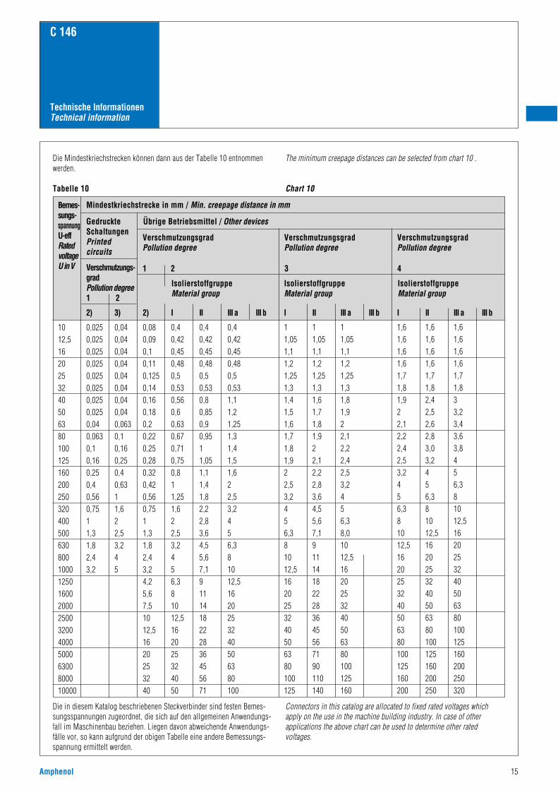
Mindestkriechstrecke in mm / Min. creepage distance in mm
GedruckteSchaltungenPrintedcircuits
Verschmutzungs-gradPollution degree1 2
2) 3) 2) I II III a III b I II III a III b I II III a III b
Übrige Betriebsmittel / Other devices
VerschmutzungsgradPollution degree
IsolierstoffgruppeMaterial group
IsolierstoffgruppeMaterial group
IsolierstoffgruppeMaterial group
1 2 3 4
VerschmutzungsgradPollution degree
VerschmutzungsgradPollution degree
Die Mindestkriechstrecken können dann aus der Tabelle 10 entnommenwerden.
Tabelle 10
The minimum creepage distances can be selected from chart 10 .
Chart 10
Die in diesem Katalog beschriebenen Steckverbinder sind festen Bemes-sungsspannungen zugeordnet, die sich auf den allgemeinen Anwendungs-fall im Maschinenbau beziehen. Liegen davon abweichende Anwendungs-fälle vor, so kann aufgrund der obigen Tabelle eine andere Bemessungs-spannung ermittelt werden.
Connectors in this catalog are allocated to fixed rated voltages whichapply on the use in the machine building industry. In case of otherapplications the above chart can be used to determine other ratedvoltages.
C 146
Technische InformationenTechnical information
Schutzarten
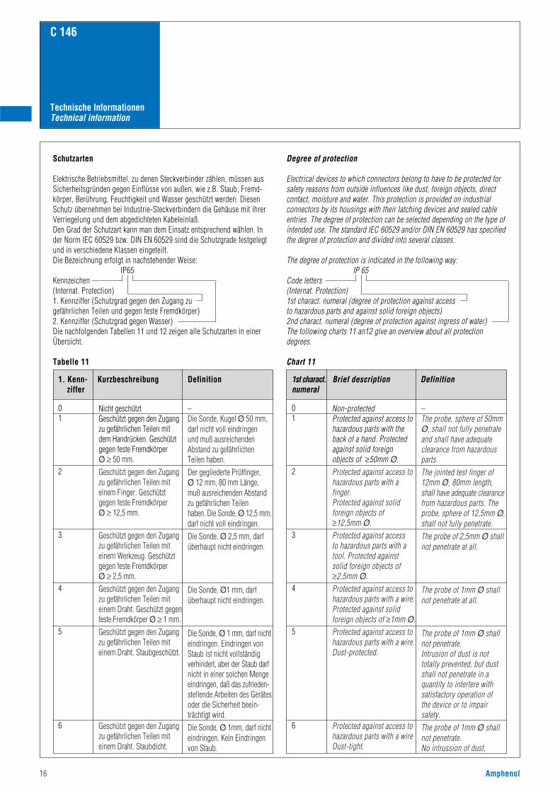
Elektrische Betriebsmittel, zu denen Steckverbinder zählen, müssen ausSicherheitsgründen gegen Einflüsse von außen, wie z.B. Staub, Fremd-körper, Berührung, Feuchtigkeit und Wasser geschützt werden. DiesenSchutz übernehmen bei Industrie-Steckverbindern die Gehäuse mit ihrerVerriegelung und dem abgedichteten Kabeleinlaß.Den Grad der Schutzart kann man dem Einsatz entsprechend wählen. Inder Norm IEC 60529 bzw. DIN EN 60529 sind die Schutzgrade festgelegtund in verschiedene Klassen eingeteilt.Die Bezeichnung erfolgt in nachstehender Weise:
IP65Kennzeichen(Internat. Protection)1. Kennziffer (Schutzgrad gegen den Zugang zu gefährlichen Teilen und gegen feste Fremdkörper)2. Kennziffer (Schutzgrad gegen Wasser)Die nachfolgenden Tabellen 11 und 12 zeigen alle Schutzarten in einerÜbersicht.
Tabelle 11
Degree of protection
Electrical devices to which connectors belong to have to be protected forsafety reasons from outside influences like dust, foreign objects, directcontact, moisture and water. This protection is provided on industrialconnectors by its housings with their latching devices and sealed cableentries. The degree of protection can be selected depending on the type ofintended use. The standard IEC 60529 and/or DIN EN 60529 has specifiedthe degree of protection and divided into several classes.
The degree of protection is indicated in the following way:IP 65
Code letters(Internat. Protection)1st charact. numeral (degree of protection against access to hazardous parts and against solid foreign objects)2nd charact. numeral (degree of protection against ingress of water)The following charts 11 an12 give an overview about all protectiondegrees.
Chart 11
1. Kenn- Kurzbeschreibung Definitionziffer
01
2
3
4
5
6
Nicht geschütztGeschützt gegen den Zugangzu gefährlichen Teilen mit dem Handrücken. Geschützt gegen feste Fremdkörper Ø ≥ 50 mm.Geschützt gegen den Zugangzu gefährlichen Teilen mit einem Finger. Geschützt gegen feste Fremdkörper Ø ≥ 12,5 mm.
Geschützt gegen den Zugang zu gefährlichen Teilen mit einem Werkzeug. Geschützt gegen feste Fremdkörper Ø ≥ 2,5 mm.Geschützt gegen den Zugang zu gefährlichen Teilen mit einem Draht. Geschützt gegen feste Fremdkörper Ø ≥ 1 mm.Geschützt gegen den Zugang zu gefährlichen Teilen mit einem Draht. Staubgeschützt.
Geschützt gegen den Zugang zu gefährlichen Teilen mit einem Draht. Staubdicht.
1st charact. Brief description Definitionnumeral
01
2
3
4
5
6
Non-protectedProtected against access tohazardous parts with theback of a hand. Protectedagainst solid foreignobjects of ≥50mm Ø.Protected against access tohazardous parts with afinger.Protected against solidforeign objects of≥12,5mm Ø.Protected against access to hazardous parts with atool. Protected againstsolid foreign objects of≥2,5mm Ø.Protected against access tohazardous parts with a wire.Protected against solidforeign objects of ≥1mm Ø.Protected against access tohazardous parts with a wire.Dust-protected.
Protected against access tohazardous parts with a wireDust-tight.
–Die Sonde, Kugel Ø 50 mm, darf nicht voll eindringen und muß ausreichenden Abstand zu gefährlichen Teilen haben.Der gegliederte Prüffinger, Ø 12 mm, 80 mm Länge, muß ausreichenden Abstandzu gefährlichen Teilen haben. Die Sonde, Ø 12,5 mm,darf nicht voll eindringen.Die Sonde, Ø 2,5 mm, darf überhaupt nicht eindringen.
Die Sonde, Ø1 mm, darf überhaupt nicht eindringen.
Die Sonde, Ø 1 mm, darf nichteindringen. Eindringen von Staub ist nicht vollständig verhindert, aber der Staub darf nicht in einer solchen Mengeeindringen, daß das zufrieden-stellende Arbeiten des Gerätes oder die Sicherheit beein-trächtigt wird.Die Sonde, Ø 1mm, darf nichteindringen. Kein Eindringen von Staub.
–The probe, sphere of 50mmØ, shall not fully penetrateand shall have adequateclearance from hazardousparts.The jointed test finger of12mm Ø, 80mm length, shall have adequate clearancefrom hazardous parts. Theprobe, sphere of 12,5mm Ø,shall not fully penetrate.The probe of 2,5mm Ø shallnot penetrate at all.
The probe of 1mm Ø shallnot penetrate at all.
The probe of 1mm Ø shallnot penetrate.Intrusion of dust is not totally prevented, but dustshall not penetrate in aquantity to interfere withsatisfactory operation of the device or to impair safety.The probe of 1mm Ø shallnot penetrate.No intrussion of dust.
16 Amphenol
Amphenol 17
C 146
Technische InformationenTechnical information
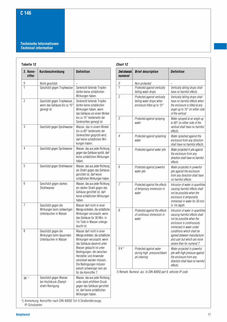
Tabelle 12
1) Anmerkung: Kennziffer nach DIN 40050 Teil 9 Straßenfahrzeuge, IP-Schutzarten
Chart 12
1) Remark: Numeral acc. to DIN 40050 part 9, vehicles IP code
2. Kenn- Kurzbeschreibung Definitionziffer
01
2
3
4
5
6
7
8
9K 1)
Nicht geschütztGeschützt gegen Tropfwasser
Geschützt gegen Tropfwasser,wenn das Gehäuse bis zu 15°geneigt ist
Geschützt gegen Sprühwasser
Geschützt gegen Spritzwasser
Geschützt gegen Strahlwasser
Geschützt gegen starkesStrahlwasser
Geschützt gegen dieWirkungen beim zeitweiligenUntertauchen in Wasser
Geschützt gegen dieWirkungen beim dauerndenUntertauchen in Wasser
Geschützt gegen Wasser bei Hochdruck-/Dampf-strahl-Reinigung
2nd charact. Brief description Definitionnumeral
01
2
3
4
5
6
7
8
9 K 1)
Non-protectedProtected against verticallyfalling water dropsProtected against verticallyfalling water drops whenenclosure tilted up to 15°
Protected against sprayingwater
Protected against splashingwater
Protected against water jets
Protected against powerfulwater jets
Protected against the effectsof temporary immersion inwater
Protected against the effectsof continous immersion inwater
Protected against waterduring high pressure/steamjet cleaning
–Senkrecht fallende Tropfendürfen keine schädlichenWirkungen haben.Senkrecht fallende Tropfendürfen keine schädlichenWirkungen haben, wenn das Gehäuse um einen Winkelbis zu 15° beiderseits derSenkrechten geneigt ist.Wasser, das in einem Winkelbis zu 60° beiderseits derSenkrechten gesprüht wird, darf keine schädlichen Wir-kungen haben.Wasser, das aus jeder Richtunggegen das Gehäuse spritzt, darfkeine schädlichen Wirkungenhaben.Wasser, das aus jeder Richtungals Strahl gegen das Gehäusegerichtet ist, darf keineschädlichen Wirkungen haben.Wasser, das aus jeder Richtungals starker Strahl gegen dasGehäuse gerichtet ist, darfkeine schädlichen Wirkungenhaben.Wasser darf nicht in einerMenge eintreten, die schädlicheWirkungen verursacht, wenndas Gehäuse für 30 Min. in 1m Tiefe in Wasser unterge-taucht ist.Wasser darf nicht in einerMenge eintreten, die schädlicheWirkungen verursacht, wenndas Gehäuse dauernd unterWasser getaucht ist unterBedingungen, die zwischenHersteller und Anwendervereinbart werden müssen. Die Bedingungen müssenjedoch schwieriger sein alsfür die Kennziffer 7.Wasser, das aus jeder Richtungunter stark erhöhtem Druckgegen das Gehäuse gerichtetist, darf keine schädlichenWirkungen haben.
–Vertically falling drops shallhave no harmful effects.Vertically falling drops shallhave no harmful effects whenthe enclosure is tilted at anyangel up to 15° on either sideof the vertical.Water sprayed at an angle upto 60° on either side of thevertical shall have no harmfuleffects.Water splashed against theenclosure from any directionshall have no harmful effects.Water projected in jets against the enclosure from any direction shall have no harmfuleffects.Water projected in powerful jets against the enclosure from any direction shall haveno harmful effects.Intrusion of water in quantitiescausing harmful effects shallnot be possible when theenclosure is temporalilyimmersed in water for 30 min.in 1m depth.Intrusion of water in quantitiescausing harmful effects shallnot be possible when theenclosure is continuouslyimmersed in water underconditions which shall beagreed between manufacturerand user but which are moresevere than for numeral 7.Water projected in powerful jets with high pressure againstthe enclosure from anydirection shall have no harmfuleffects.
C 146
Technische InformationenTechnical information
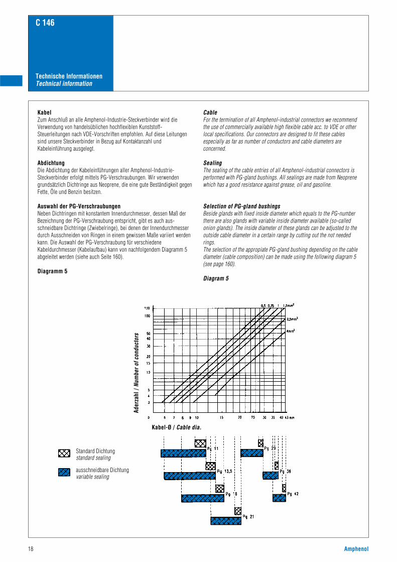
KabelZum Anschluß an alle Amphenol-Industrie-Steckverbinder wird dieVerwendung von handelsüblichen hochflexiblen Kunststoff-Steuerleitungen nach VDE-Vorschriften empfohlen. Auf diese Leitungensind unsere Steckverbinder in Bezug auf Kontaktanzahl undKabeleinführung ausgelegt.
AbdichtungDie Abdichtung der Kabeleinführungen aller Amphenol-Industrie-Steckverbinder erfolgt mittels PG-Verschraubungen. Wir verwendengrundsätzlich Dichtringe aus Neoprene, die eine gute Beständigkeit gegenFette, Öle und Benzin besitzen.
Auswahl der PG-VerschraubungenNeben Dichtringen mit konstantem Innendurchmesser, dessen Maß derBezeichnung der PG-Verschraubung entspricht, gibt es auch aus-schneidbare Dichtringe (Zwiebelringe), bei denen der Innendurchmesserdurch Ausschneiden von Ringen in einem gewissen Maße variiert werdenkann. Die Auswahl der PG-Verschraubung für verschiedeneKabeldurchmesser (Kabelaufbau) kann von nachfolgendem Diagramm 5abgeleitet werden (siehe auch Seite 160).
Diagramm 5
CableFor the termination of all Amphenol-industrial connectors we recommendthe use of commercially available high flexible cable acc. to VDE or otherlocal specifications. Our connectors are designed to fit these cablesespecially as far as number of conductors and cable diameters areconcerned.
SealingThe sealing of the cable entries of all Amphenol-industrial connectors isperformed with PG-gland bushings. All sealings are made from Neoprenewhich has a good resistance against grease, oil and gasoline.
Selection of PG-gland bushingsBeside glands with fixed inside diameter which equals to the PG-numberthere are also glands with variable inside diameter available (so-calledonion glands). The inside diameter of these glands can be adjusted to theoutside cable diameter in a certain range by cutting out the not neededrings.The selection of the appropiate PG-gland bushing depending on the cablediameter (cable composition) can be made using the following diagram 5(see page 160).
Diagram 5
Ader
zahl
/ Nu
mbe
r of c
ondu
ctor
s
Kabel-Ø / Cable dia.
18 Amphenol
Standard Dichtungstandard sealing
ausschneidbare Dichtungvariable sealing
Amphenol 19
C 146
Technische InformationenTechnical information
Notizen Remarks
20 Amphenol
C 146
AbschirmungAbschirmung innerer oder äußerer elektrischer Felder durch Bildung einer Äquipotentialfläche inForm von Metallklappen oder Metallisierungen auf der Innen- und Außenseite von Kappen ausKunststoff. Die Abschirmung wird in der Regel mit dem Schirmgeflecht des angeschlossenen Kabelsund mit dem Gerätegehäuse verbunden.
Bemessungsgrößen, elektrische– Bemessungsspannung ist die Spannung, für die der Steckverbinder oder die Steckvorrichtungbemessen ist und auf die bestimmte Betriebseigenschaften bezogen werden. – Bemessungsstrom ist der Strom, den ein Steckverbinder oder eine Steckvorrichtung gleichzeitigdurch alle Kontakte dauernd (nicht intermittierend) führen kann, ohne daß dabei die obereGrenztemperatur überschritten wird. – Schaltleistung einer Steckvorrichtung ist die Leistung, welche die Steckvorrichtung unterfestgelegten Bedingungen schalten kann. –Prüfspannung ist die Spannung, der ein Steckverbinder oder eine Steckvorrichtung beivorgegebenen Bedingungen ohne Durch- oder Überschlag widersteht.
BügelverriegelungVerriegelung von zwei Hälften eines Steckverbinderpaares durch ein formschlüssiges Element, dasdurch einen als Bügel ausgestalteten Hebel betätigt wird. Erst wenn die beiden Hälften vollständigzusammengesteckt sind, kommt der Bügel in seine Endlage.
CrimpbackenDerjenige Teil eines Crimpwerkzeugs, der den Crimpbereich verformt. Er besteht üblicherweise ausdem Crimpamboß, dem Crimpstempel und dem Positionierstück.
CrimpbereichDer Bereich der Crimphülse, in dem die Crimpverbindung durch Druckverformung oder Druckum-formung der Hülse um den Leiter herum ausgeführt ist.
CrimphülseEine Anschlußhülse, die einen oder mehrere Leiter aufnehmen kann und durch Anwendung einesCrimpwerkzeugs gecrimpt werden kann.
CrimpverbindungDurch systematisches Verformen einer Crimphülse um abisolierte Leiter herum hergestellte,dauerhafte elektrische und mechanische Verbindung; Crimpverbindung siehe IEC 60352-2, DIN EN 60 352-2 (siehe auch Katalog „Werkzeuge“)
DurchgangswiderstandDer elektrische Widerstand in einem gesteckten bzw. geschalteten Kontaktpaar, gemessen zwischenden Anschlußpunkten unter vorgeschriebenen Meßbedingungen. Prüfungen nach ICE 60512-2, DIN EN 60 512-2
Elektromagnetische EinflüsseBei Steckverbindern werden unerwünschte elektromagnetische Einflüsse auf die zu verbindendenLeitungen bzw. auf die Umgebung durch Abschirmung verhindert.
GehäuseTeil eines Steckverbinders, in dem Kontaktträger und Kontakte montiert sind. Es kann zurVerriegelung dienen.
GrenztemperaturenUntere und obere Temperaturen, die nicht zu einer Schädigung der Werkstoffe führen; dazwischenliegt der Betriebstemperaturbereich.– Untere Grenztemperatur: Die tiefste zulässige Temperatur, bei der ein Steckverbinder oder eineSteckvorrichtung noch betrieben werden darf.– Obere Grenztemperatur: Die höchste zulässige Temperatur, bei der ein Steckverbinder oder eineSteckvorrichtung noch betrieben werden darf. Sie ist die Summe aus Eigenerwärmung (ein-schließlich Kontakterwärmung) und Umgebungstemperatur.
IsolationswiderstandWiderstand der Isolierung zwischen zwei leitfähigen Teilen. Isoliervermögen eines Werkstoffes, derzwei benachbarte Kontakte oder einen Kontakt gegen Masse möglichst hochohmig trennt. Meß- undPrüfverfahren nach IEC 60512-2, 3a, DIN EN 60 512-2
IsolierstoffgruppeEinteilung von Isolierstoffen entsprechend ihren CTI-Werten (CTI = Comperative Tracking Index /Vergleichszahl der Kriechwegbildung).
Kompatible SteckverbinderZwei Steckverbinder sind kompatibel, wenn sie mechanisch austauschbar und zusammensteckbarsind und den gleichen technischen Anforderungen entsprechen.
KontaktgrößeKennzeichnung zur Differenzierung der Kontakte nach folgendem Systemena) Kennzeichnungssystem: Kennzeichnung des Kontaktes nach der maximal anschließbarenLeitergröße (AWG American Wire Gauge);
b) Strombelastbarkeitssystem: Kennzeichnung des Kontaktes nach seiner maximalenStrombelastbarkeit.c) Querschnittsystem: Kennzeichnung des Kontaktes nach dem maximal anschließbarenLeiterquerschnitt. Leiterwiderstand.
KontaktmaterialDie Wahl des Kontaktmaterials – meist Kupfer oder Kupferlegierungen – hängt von den gewünschtenEigenschaften des Steckverbinders ab. Hierbei spielen Durchgangswiderstand; Steck- und Ziehkräfteeine maßgebliche Rolle. Neben Steckhäufigkeit und Umwelteinflüssen bestimmen diese auch die Artder Oberflächenüberzüge Nickel, Zinn, Gold, Silber, Palladium. Sie werden galvanisch oderwalztechnisch aufgebracht.
KriechstreckenKürzeste Entfernung zwischen spannungsführenden Teilen auf der Oberfläche von Isolierkörpern,sofern festgelegte Mindestmaße vorliegen (Kriechstreckenverlängerung). Die Abstände dienen derSicherheit gegen Überschläge. Sie werden in Abhängigkeit von der Reihenspannung, denAnwendungsbedingungen und den Eigenschaften des Isolierwerkstoffes festgelegt. Dieunterschiedliche Kriechstromfestigkeit der Isolierstoffe ist bei der Festlegung der Kriechstrecken zubeachten (DIN VDE 0110.)
LebensdauerAnzahl der Steckzyklen, die noch nicht zum Durchrieb der leitenden Kontaktflächen führt und denKontaktwiderstand nicht unzulässig erhöht. Meß- und Prüfverfahren nach IEC 60512-59,DIN EN 60512-5
LuftstreckenKürzeste, als Fadenmaß gemessene Entfernung zwischen zwei spannungsführenden Metallteilen inder Luft, nach DIN VDE 0110.
Rechteck-VerbinderSteckverbinder mit vorwiegend rechteckiger Form des Steckgesichtes.
SchaltleistungDie Schaltleistung einer Steckvorrichtung ist die Leistung, die die Steckvorrichtung unterfestgelegten Bedingungen schalten kann.
SpannungsfestigkeitSpannung, der ein Steckverbinder oder eine Steckvorrichtung bei vorgegebenen Bedingungen ohneDurchschlag oder Überschlag widersteht. Die Spannungsfestigkeit liegt über der Nennspannung, siedient zum Nachweis des Isoliervermögens des Steckverbinders.
SteckverbinderEin Bauelement, das es gestattet elektrische Leiter anzuschließen, und dazu bestimmt ist, mit einempassenden Gegenstück Verbindungen herzustellen und zu trennen. Steckverbinder sind Betriebs-mittel, die bei bestimmungsgemäßer Verwendung (unter elektrischer Spannung) nicht gesteckt odergetrennt werden dürfen (im Gegensatz zur Steckvorrichtung). Nach der Befestigung werden freie undfeste Steckverbinder unterschieden. Der Steckverbinder besteht aus dem Steckverbindergehäuse undden Kontaktelementen. Das Steckverbindergehäuse enthält den Kontakteinsatz.
SteckverbindungEine elektrische Steckverbindung besteht aus zwei Steckverbindern, d. h. aus mindestens zweiKontaktelementen. Alle weiteren Komponenten wie Gehäuse, Kontaktträger, Kontakthalterung usw.,erfüllen sekundäre Funktionen.
SteckvorrichtungEin Bauelement wie ein Steckverbinder, das bei bestimmungsgemäßer Verwendung unter elektrischerSpannung oder Last gesteckt oder getrennt wird (im Gegensatz zu Steckverbindern). Der Schutz-leiterkontakt muß während des Steckens vor- und während des Trennens nacheilen (voreilenderKontakt).
SteckzyklenMechanisches Betätigen von Steckverbindern und Steckvorrichtungen durch Stecken und Ziehen. EinSteckzyklus besteht aus je einem Steck- und Ziehvorgang.
ÜberspannungskategorieEin Zahlenwert, der eine Stehstoßspannung festlegt. Er werden die Überspannungskategorien I, II, IIIund IV verwendet.
VerschmutzungsgradZahlenwert, der die zu erwartende Verschmutzung der Mikro-Umgebung angibt. Er werden dieVerschmutzungsgrade 1, 2, 3 und 4 verwendet.
Voreilender KontaktErfordert der Schaltungsaufbau, daß aus Schutzgründen, z. B. für Schutzleiter, ein oder mehrereKontakte eines Steckverbinders beim Stecken zuerst Kontakt herstellen oder beim Ziehen als letztegetrennt werden, sind Steckverbinder mit voreilenden Kontakten (Stift bzw. Messer, Buchse oderFeder) zu verwenden.
Steckverbinderbegriffe
Amphenol 21
C 146
American Wire Gauge (AWG)System of numerical designations for wire sizes, based on specified ranges of cross-sectional areas. Starts with 4/0 (000) at the largest size, going to 3/0, 2/0, 1/0, 1, 2, and up to 40 and beyond for thesmallest size. A step of one AWG number corresponds to a reduction of cross-sectional area of appr. 20 %.
AttenuationA reduction of power. Occurs naturally when waves travel through lines, wave guides, or media such as airor water. Is produced additionally by imperfections in electrical or optical connections (attenuation in fibreoptics), e. g. contact resistance, mismatch, etc.
Bulkhead connectorConnector designed to be inserted into a panel cutout from the rear of the panel, thus forming part of thebarrier between two spaces. Back-mounted.
ClearanceThe shortest distance in air between two conductive parts, see IEC 60664.
Climatic stabilityGeneral term describing the behavior of components under various climatic conditions, e. g. high and lowtemperatures, tropical climate, high humidity, moist heat, fungus, atmospheric conditions (industialatmosphere), reduced air pressure, etc. Climatic conditions for test purposes are explained in IEC 60068,DIN 46 040.
ConnectorA component which terminates conductors for the purpose of providing connection and disconnection to a suitable mating component which shall not be engaged or disengaged when live. Depending on thefastening to a cabinet, panel, rack etc. or a cable, they are classified as fixed or free connectors. Aconnector comprises one or more contacts and a housing which may have a separate connector insert anda separate outer housing or shell.
Connector housingThe part of a connector into which the insert and the contacts are assembled. It may function as part of thelocking mechanism.
Connector insertAn insulating element designed to support and position contacts in a connector housing.
Connector lifeThe number of mating cycles prior to abrasion of the conductive contact surface and which does not resultin a significant rise of the contact resistance. Tests according to test 9a of ICE 60512-5 / DIN EN 60512Part 5.
ContactThe conductive element in a connector which mates with a corresponding element to provide an electricalpath.
Contact resistanceThe electrical resistance of a mated set of contacts under specified conditions. Tested according to tests 2a,2b, 2c, of IEC 60 512 / DIN EN 60 512.
Contact sizeThe designation used to differentiate one contact from another. It may be denoted by one of the followingnumbering systems:– numbering system: assigned numbers used to denote the size of the contact and its related conductoraccomodation (e. g. in AWG units), – current rating system: the related current-carrying capacity is used to denote the size of the contact, – cross-sectional area system: reference is made to the cross-sectional area of the maximum conductoraccommodation to denote the size of the contact, e. g. in mm2.
Creepage distanceThe shortest distance along the surface of the insulating material between two conductive parts. The longerthe distance, the lesser the risk of arc damage or tracking. Minimum creepage distances are specifiedaccording to the rated voltage and the applicable pollution degree and Comperative Tracking Index.
Crimped connectionA solderless connection made by crimping. IEC 60352-2 / DIN IEC 60352 Part 2.
Crimping dieThat part of a crimping tool which forms the crimp(s) and usually incorporates the crimp anvil(s) and thecrimp indentor(s).
Derating curveThe method for determining derating is specified in IEC 60 512-3. Here the combination of ambienttemperature (Tu) and the current (J) leading to the same maximum allowable temperature (Tb) at thehottest point of the connector are plotted.
DINDeutsches Institut für Normung. A German standards organization.
Electromagnetic interference (EMI)General term describing the undesirable effects of the immission or emission of radio frequency fields. In connectors electromagnetic interference is prevented by shielding. Shielded connectors normallyprovide means to connect the screens of attached cables.
Funnel entry (restricted entry C146 D series)Flared or widened entrance to a conductor barrel permitting easier insertion of the conductor.
Insertion or withdrawal forceThe force required to fully insert or withdraw a set of mating connectors without the effect of coupling,locking or similar devices. The insertion force is usually greater than the withdrawal force.
Insulation gripThe area of a crimp contact that has been reshaped around the insulation of the conductor by compressionduring the crimping operation.
Insulation resistanceThe resistance of the insulation between two conductive elements, in particular, the resistance between twocontacts or between a contact and a metallic housing or shield. Tested according to test 3a of IEC 60512-2 /DIN IEC 60512 Part 2.
IntermateableTwo connectors are intermateable when they are capable of being connected electrically and mechanicallybut without regard to their performance and intermountability.
LocatorIn a crimping tool the device used for positioning a crimp contact or terminal end.
Locking leverA mechanical locking device operated by actuating a lever, designed to hold two mated connectorstogether. Typically the lever can only be brought fully home if the two connectors are correctly mated.
Mating cycleOne mating cycle comprises one insertion and one withdrawal operation. Term used in the definition ofconnector life.
Material groupClassification of insulation materials according to their CTI values (CTI = Comperative Tracking Index)
Overvoltage categoryA numeral defining a transient overvoltage condition. Overvoltage categories I, II, III and IV are used.
Plug-and-socket device (PSD)A component like a connector which may be engaged or disengaged in normal use, when live or underload. Note: In the sense of this document the term - live- is used if contacts are under voltage notnecessarily with a current flowing across the contacts. The term - load - is used if a current is flowingacross the contacts.
Rated currentA current value assigned by the manufacturer which the connector or PSD can carry continuously (withoutinterruption) and simultaneously through all its contacts wired with the largest conductor preferrably at anambient temperature of 40 °C without the upper temperature being exceeded.
Shield, shieldingShielding of internal or external electric fields by means of a plane with a uniform electric potential, formedby metal shells or metallic layers on the inside or outside of plastic shells. The shield is normallyconnected to the shielding braid of the cable and/or chassis ground.
Terminal blockAn assembly of terminals in a housing or body of insulating material to facilitate interconnection betweenmultiple conductors. Also called terminal strip or barrier blocks if the terminals are separated by aninsulation barrier.
Wire rangeThe range of wire cross sections which is compatible with the dimensions the terminals of the contact (wire barrel). The wire range is expressed in mm2 or in AWG numbers.
Connector glossary

22 Amphenol
C 146 D
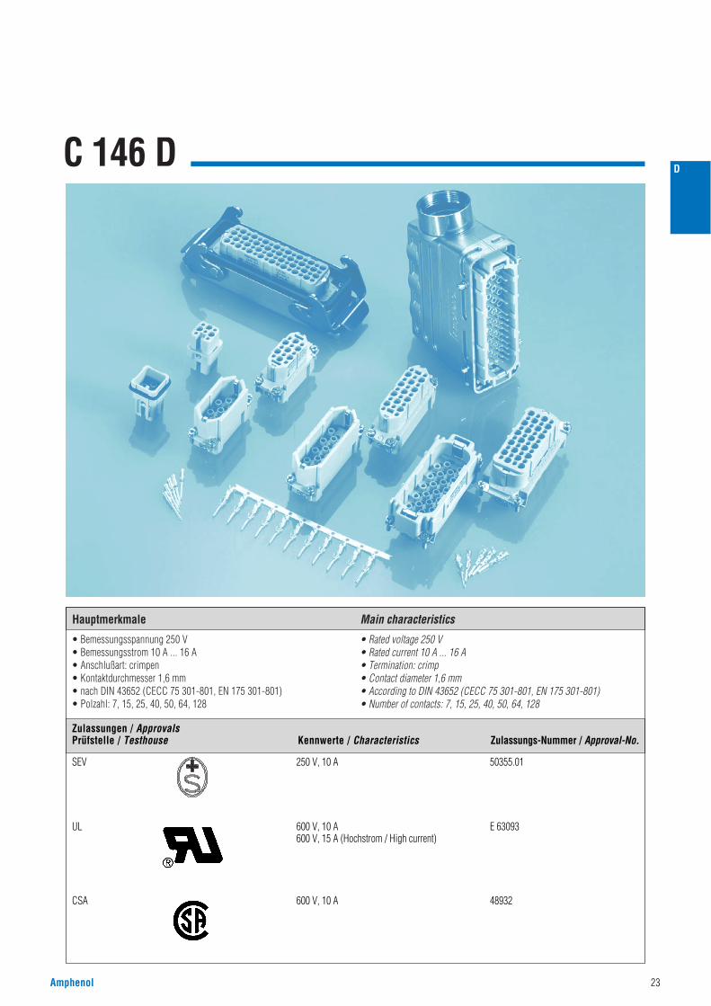
• Bemessungsspannung 250 V• Bemessungsstrom 10 A ... 16 A• Anschlußart: crimpen• Kontaktdurchmesser 1,6 mm• nach DIN 43652 (CECC 75 301-801, EN 175 301-801)• Polzahl: 7, 15, 25, 40, 50, 64, 128
• Rated voltage 250 V• Rated current 10 A ... 16 A• Termination: crimp• Contact diameter 1,6 mm• According to DIN 43652 (CECC 75 301-801, EN 175 301-801)• Number of contacts: 7, 15, 25, 40, 50, 64, 128
Hauptmerkmale Main characteristics
Amphenol 23
D
SEV 250 V, 10 A 50355.01
UL 600 V, 10 A E 63093600 V, 15 A (Hochstrom / High current)
CSA 600 V, 10 A 48932
Zulassungen / ApprovalsPrüfstelle / Testhouse Kennwerte / Characteristics Zulassungs-Nummer / Approval-No.
24 Amphenol
D
KurzinformationBrief information
C 146 D
Allgemeine Hinweise
General information
• Kontakteinsätze ohne Crimpkontakte, Crimpwerkzeuge siehe separater Katalog „Werkzeuge“.• Kontakte müssen separat bestellt werden, Verarbeitungs- und Montagehinweise siehe Katalog „Werkzeuge“.• Für die Einsätze der Serie C 146 D werden die hohen Gehäusebauformen empfohlen.• Steckverbinder der Serie C 146 D dürfen unter Spannung, jedoch nicht unter Strom betätigt werden. Werden die
Steckverbinder als Steckvorrichtung eingesetzt, ist der Strom auf 15 % des Bemessungsstroms zu begrenzen.• Für Kontakteinsätze für gedrehte Kontakte werden Führungsstifte und Führungsbuchsen empfohlen (siehe Seite 164).
• Contact inserts without crimp contacts, crimping tools see separate catalog „Tools“.• Contacts must be ordered separately, processing instructions see catalog „Tools“.• We recommend for C 146 D inserts to use the high style housings / hoods.• Connectors series C146 D may be engaged or disengaged when live but without electrical load.
If these connectors are used as plug and socket device, the load shall be reduced to 15 % of the rated current.• For contact inserts for turned contacts, guide pins and guide socket are recommanded to use (see page 164).
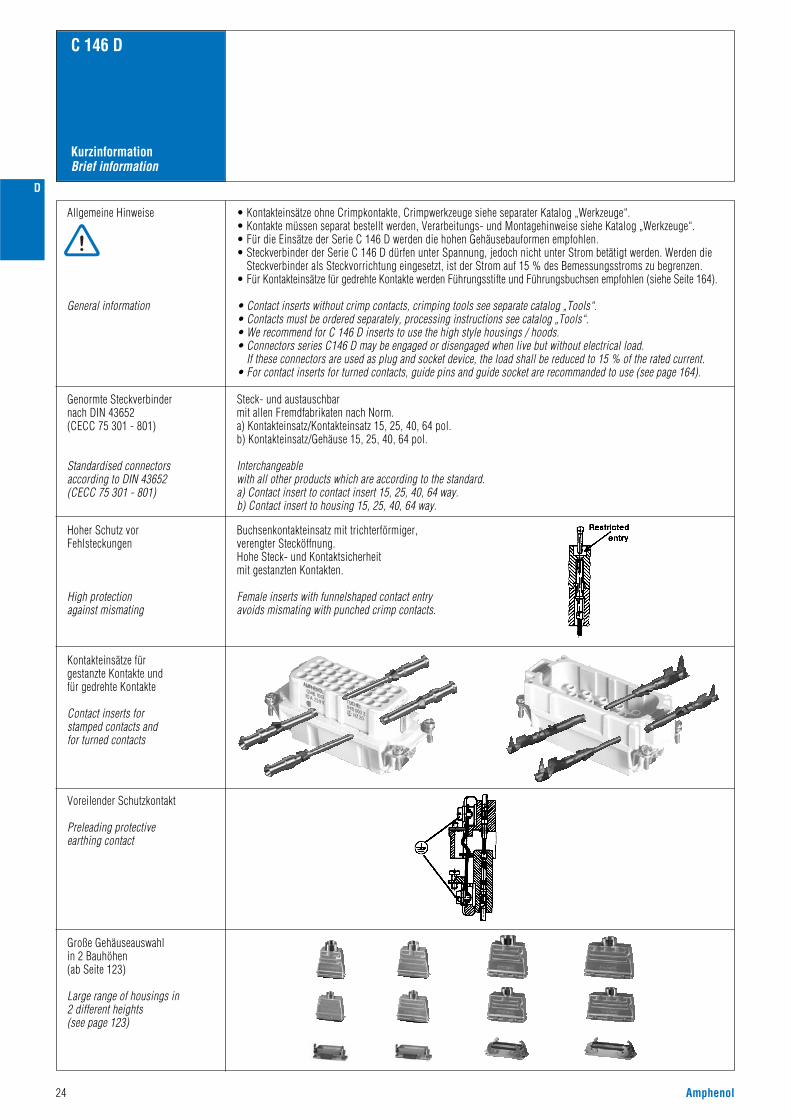
Hoher Schutz vorFehlsteckungen
High protectionagainst mismating
Buchsenkontakteinsatz mit trichterförmiger,verengter Stecköffnung.Hohe Steck- und Kontaktsicherheit mit gestanzten Kontakten.
Female inserts with funnelshaped contact entry avoids mismating with punched crimp contacts.
Kontakteinsätze für gestanzte Kontakte und für gedrehte Kontakte
Contact inserts for stamped contacts and for turned contacts
Voreilender Schutzkontakt
Preleading protective earthing contact
Große Gehäuseauswahlin 2 Bauhöhen(ab Seite 123)
Large range of housings in2 different heights(see page 123)
Genormte Steckverbindernach DIN 43652(CECC 75 301 - 801)
Standardised connectorsaccording to DIN 43652(CECC 75 301 - 801)
Steck- und austauschbarmit allen Fremdfabrikaten nach Norm.a) Kontakteinsatz/Kontakteinsatz 15, 25, 40, 64 pol.b) Kontakteinsatz/Gehäuse 15, 25, 40, 64 pol.
Interchangeablewith all other products which are according to the standard.a) Contact insert to contact insert 15, 25, 40, 64 way.b) Contact insert to housing 15, 25, 40, 64 way.
D
Amphenol 25
Crimp TechnikCrimp technology
C 146 D
1) Erläuterung der Bestell-Nr. für die Kontakte siehe Seite 41) Explanation of the Part No. for contacts see page 4
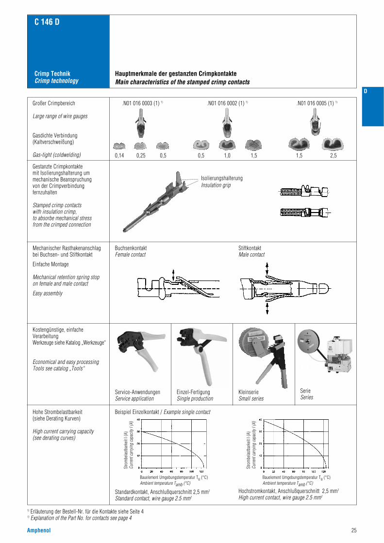
Großer Crimpbereich
Large range of wire gauges
Gasdichte Verbindung(Kaltverschweißung)
Gas-tight (coldwelding)
Gestanzte Crimpkontakte mit Isolierungshalterung ummechanische Beanspruchung von der Crimpverbindungfernzuhalten
Stamped crimp contacts with insulation crimp,to absorbe mechanical stress from the crimped connection
Mechanischer Rasthakenanschlagbei Buchsen- und Stiftkontakt
Einfache Montage
Mechanical retention spring stop on female and male contact
Easy assembly
Kostengünstige, einfacheVerarbeitungWerkzeuge siehe Katalog „Werkzeuge“
Economical and easy processingTools see catalog „Tools“
Hohe Strombelastbarkeit(siehe Derating Kurven)
High current carrying capacity(see derating curves)
Beispiel Einzelkontakt / Example single contact
Standardkontakt, Anschlußquerschnitt 2,5 mm2
Standard contact, wire gauge 2.5 mm2
Hochstromkontakt, Anschlußquerschnitt 2,5 mm2
High current contact, wire gauge 2.5 mm2
.N01 016 0003 (1) 1) .N01 016 0002 (1) 1) .N01 016 0005 (1) 1)
Hauptmerkmale der gestanzten CrimpkontakteMain characteristics of the stamped crimp contacts
IsolierungshalterungInsulation grip
KleinserieSmall series
SerieSeries
BuchsenkontaktFemale contact
StiftkontaktMale contact
Service-AnwendungenService application
Einzel-FertigungSingle production
Stro
mbe
last
bark
eit I
(A)
Curre
nt ca
rryin
g ca
pacit
y I (A
)
Bauelement Umgebungstemperatur Tu (°C)Ambient temperature Tamb (°C)
Stro
mbe
last
bark
eit I
(A)
Curre
nt ca
rryin
g ca
pacit
y I (A
)
Bauelement Umgebungstemperatur Tu (°C)Ambient temperature Tamb (°C)
1,5 2,50,5 1,0 1,50,14 0,25 0,5
26 Amphenol
D
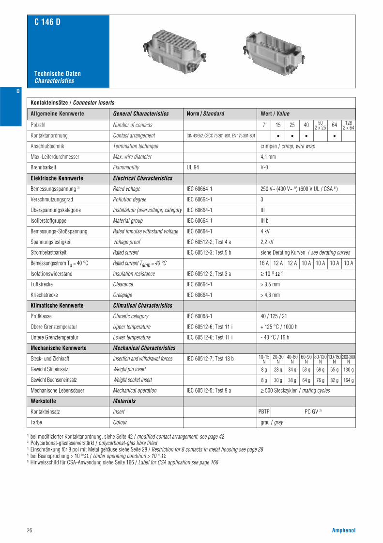
Norm / Standard Wert / ValueAllgemeine Kennwerte
Kontakteinsätze / Connector inserts
Polzahl
DIN 43 652; CECC 75 301-801, EN 175 301-801Kontaktanordnung
Number of contacts
Contact arrangement
Anschlußtechnik Termination technique
V-0
crimpen / crimp, wire wrap
Max. Leiterdurchmesser Max. wire diameter 4,1 mm
7 15 25 40 502 x 25 64
• • • •
1282 x 64
Flammability
C 146 D
UL 94Brennbarkeit
250 V~ (400 V~ 1)) (600 V UL / CSA 5))
3
III
III b
4 kV
2,2 kV
siehe Derating Kurven / see derating curves
≥ 10 12 Ω 4)
Electrical Characteristics
Rated voltage
Pollution degree
Installation (overvoltage) category
Material group
Rated impulse withstand voltage
Voltage proof
IEC 60664-1
IEC 60664-1
IEC 60664-1
IEC 60664-1
IEC 60664-1
IEC 60512-2; Test 4 a
IEC 60512-3; Test 5 b
IEC 60512-2; Test 3 a
IEC 60068-1
IEC 60512-7; Test 13 b
IEC 60512-5; Test 9 a
Rated current
Insulation resistance
Climatical Characteristics
Climatic category
Mechanical Characteristics
Insertion and withdrawal forces
Weight pin insert
Weight socket insert
Mechanical operation
Insert
40 / 125 / 21
80-120N
100-150N
200-300N
60-90N
40-60N
20-30N
10-15N
8 g 28 g 34 g 53 g 68 g 65 g 130 g
8 g 30 g 38 g 64 g 76 g 82 g 164 g
≥ 500 Steckzyklen / mating cycles
PBTP PC GV 2)
grau / grey
Elektrische Kennwerte
Bemessungsspannung 3)
Verschmutzungsgrad
Überspannungskategorie
Isolierstoffgruppe
Bemessungs-Stoßspannung
Spannungsfestigkeit
Strombelastbarkeit
16 A 12 A 12 A 10 A 10 A 10 A 10 ARated current Tamb = 40 °CBemessungsstrom Tu = 40 °C
Isolationswiderstand
> 3,5 mmIEC 60664-1ClearanceLuftstrecke
> 4,6 mmIEC 60664-1CreepageKriechstrecke
Klimatische Kennwerte
Prüfklasse
IEC 60512-6; Test 11 iUpper temperature
Lower temperature
+ 125 °C / 1000 hObere Grenztemperatur
Untere Grenztemperatur IEC 60512-6; Test 11 i - 40 °C / 16 h
Mechanische Kennwerte
Steck- und Ziehkraft
Gewicht Stifteinsatz
Gewicht Buchseneinsatz
Mechanische Lebensdauer
Werkstoffe
Kontakteinsatz
Farbe Colour
Materials
General Characteristics
1) bei modifizierter Kontaktanordnung, siehe Seite 42 / modified contact arrangement, see page 422) Polycarbonat-glasfaserverstärkt / polycarbonat-glas fibre filled3) Einschränkung für 8 pol mit Metallgehäuse siehe Seite 28 / Restriction for 8 contacts in metal housing see page 284) bei Beanspruchung > 10 10 Ω / Under operating condition > 10 10 Ω5) Hinweisschild für CSA-Anwendung siehe Seite 166 / Label for CSA application see page 166
Technische DatenCharacteristics
Amphenol 27
D
C 146 D
Norm / Standard Wert / ValueAllgemeine Kennwerte
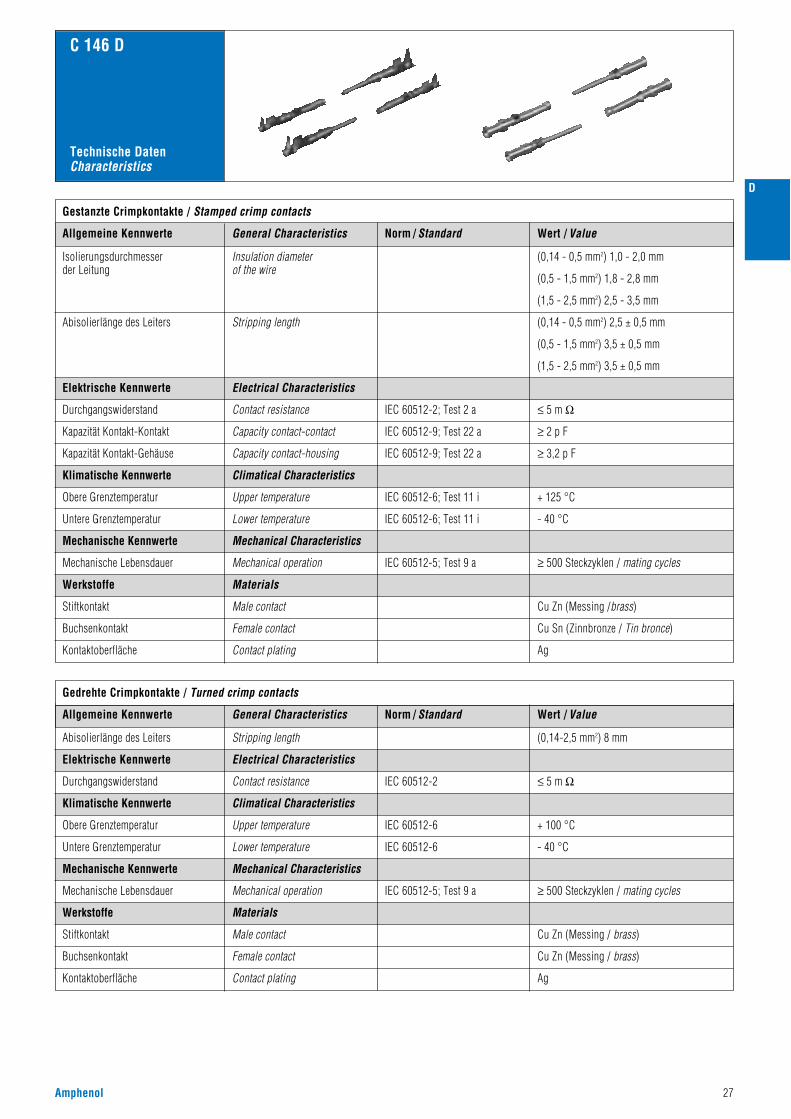
Gestanzte Crimpkontakte / Stamped crimp contacts
Isolierungsdurchmesserder Leitung
Abisolierlänge des Leiters
IEC 60512-2; Test 2 a
IEC 60512-9; Test 22 a
IEC 60512-9; Test 22 a
≤ 5 m Ω
(0,14 - 0,5 mm2) 1,0 - 2,0 mm
(0,5 - 1,5 mm2) 1,8 - 2,8 mm
(1,5 - 2,5 mm2) 2,5 - 3,5 mm
(0,14 - 0,5 mm2) 2,5 ± 0,5 mm
(0,5 - 1,5 mm2) 3,5 ± 0,5 mm
(1,5 - 2,5 mm2) 3,5 ± 0,5 mm
≥ 2 p F
≥ 3,2 p F
Elektrische Kennwerte
Durchgangswiderstand
Kapazität Kontakt-Kontakt
Elektrische Kennwerte Electrical Characteristics
Kapazität Kontakt-Gehäuse
IEC 60512-5; Test 9 a
IEC 60512-2
≥ 500 Steckzyklen / mating cycles
Mechanische Kennwerte
Klimatische Kennwerte
Mechanische Lebensdauer
Werkstoffe
Cu Zn (Messing /brass)Stiftkontakt
Buchsenkontakt
Kontaktoberfläche
Abisolierlänge des Leiters Stripping length
Gedrehte Crimpkontakte / Turned crimp contacts
Insulation diameterof the wire
Stripping length
Electrical Characteristics
Contact resistance
Capacity contact-contact
Capacity contact-housing
Mechanical Characteristics
Climatical Characteristics
Mechanical operation
IEC 60512-6; Test 11 i
IEC 60512-6; Test 11 i
+ 125 °CObere Grenztemperatur Upper temperature
- 40 °CUntere Grenztemperatur Lower temperature
Klimatische Kennwerte Climatical Characteristics
IEC 60512-6
IEC 60512-6
+ 100 °CObere Grenztemperatur Upper temperature
- 40 °CUntere Grenztemperatur Lower temperature
Male contact
Female contact
Contact plating
Materials
General Characteristics
Norm / Standard Wert / ValueAllgemeine Kennwerte General Characteristics
Cu Sn (Zinnbronze / Tin bronce)
Ag
(0,14-2,5 mm2) 8 mm
≤ 5 m Ω
Mechanische Kennwerte
Werkstoffe
Mechanical Characteristics
Materials
IEC 60512-5; Test 9 a
Durchgangswiderstand
Mechanische Lebensdauer
Contact resistance
Mechanical operation ≥ 500 Steckzyklen / mating cycles
Stiftkontakt
Buchsenkontakt
Kontaktoberfläche
Male contact
Female contact
Contact plating
Cu Zn (Messing / brass)
Cu Zn (Messing / brass)
Ag
Technische DatenCharacteristics
28 Amphenol
D
Bezeichnung - AbbildungDescription - Figure
MaßzeichnungDrawing
Bestell Nr. / Part No.Stifteinsatz / Male insert Buchseneinsatz / Female insert
C 146 D
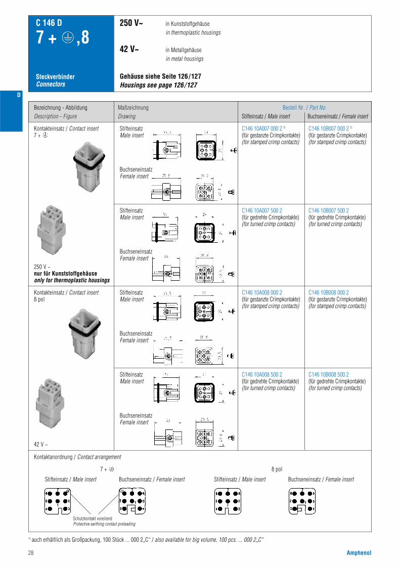
7 + ,8
SteckverbinderConnectors
Kontakteinsatz / Contact insert 7 +
250 V ~nur für Kunststoffgehäuseonly for thermoplastic housings
StifteinsatzMale insert
BuchseneinsatzFemale insert
StifteinsatzMale insert
BuchseneinsatzFemale insert
Gehäuse siehe Seite 126/127 Housings see page 126/127
250 V~ in Kunststoffgehäusein thermoplastic housings
42 V~ in Metallgehäusein metal housings
Kontaktanordnung / Contact arrangement
Stifteinsatz / Male insert
Schutzkontakt voreilendProtective earthing contact preleading
C146 10A007 000 2 1)
(für gestanzte Crimpkontakte)(for stamped crimp contacts)
C146 10B007 000 2 1)
(für gestanzte Crimpkontakte)(for stamped crimp contacts)
C146 10A007 500 2(für gedrehte Crimpkontakte)(for turned crimp contacts)
C146 10B007 500 2(für gedrehte Crimpkontakte)(for turned crimp contacts)
Kontakteinsatz / Contact insert 8 pol
42 V ~
1) auch erhältlich als Großpackung, 100 Stück ... 000 2„C“ / also available for big volume, 100 pcs. ... 000 2„C“
StifteinsatzMale insert
BuchseneinsatzFemale insert
Buchseneinsatz / Female insert Stifteinsatz / Male insert Buchseneinsatz / Female insert
StifteinsatzMale insert
BuchseneinsatzFemale insert
C146 10A008 000 2(für gestanzte Crimpkontakte)(for stamped crimp contacts)
C146 10A008 500 2(für gedrehte Crimpkontakte)(for turned crimp contacts)
C146 10B008 000 2(für gestanzte Crimpkontakte)(for stamped crimp contacts)
C146 10B008 500 2(für gedrehte Crimpkontakte)(for turned crimp contacts)
7 + 8 pol

Amphenol 29
D
LieferformSupplied as
Gestanzte Einzelkontakte / Stamped single contacts
für Leiterquerschnittfor wire gauge
AWG StückzahlPieces
Bestell Nr. 1) / Part No. 1)
Stiftkontakt / Male contact Buchsenkontakt / Female contact
C 146 D
7 + ,8
CrimpkontakteCrimp contacts
StandardHochstromHigh current
StandardHochstromHigh current
StandardHochstromHigh current
StandardHochstromHigh current
0,14 - 0,5 mm2
0,5 - 1,5 mm2
1,5 - 2,5 mm2
0,5 - 1,5 mm2
1,5 - 2,5 mm2
0,14 - 0,5 mm2
0,5 - 1,5 mm2
1,5 - 2,5 mm2
0,5 - 1,5 mm2
1,5 - 2,5 mm2
0,14 - 0,5 mm2
0,5 - 1,5 mm2
1,5 - 2,5 mm2
0,5 - 1,5 mm2
1,5 - 2,5 mm2
0,14 - 0,5 mm2
0,5 - 1,5 mm2
1,5 - 2,5 mm2
0,5 - 1,5 mm2
1,5 - 2,5 mm2
26 - 2020 - 1616 - 1420 - 1616 - 14
26 - 2020 - 1616 - 1420 - 1616 - 14
26 - 2020 - 1616 - 1420 - 1616 - 1426 - 2020 - 1616 - 1420 - 1618 - 14
200200100200100
100100100100100
2000200020002000200020002000200020002000
VN01 016 0003 (1)VN01 016 0002 (1)VN01 016 0005 (1)VN01 016 0015 1VN01 016 0016 1
ZN01 016 0003 (1)ZN01 016 0002 (1)ZN01 016 0005 (1)ZN01 016 0015 (1)ZN01 016 0016 (1)
HN01 016 0003 (1)HN01 016 0002 (1)HN01 016 0005 (1)HN01 016 0015 (1)HN01 016 0016 (1)TN01 016 0003 (1)TN01 016 0002 (1)TN01 016 0005 (1)TN01 016 0015 (1)TN01 016 0016 (1)
ZN02 016 0003 (1)ZN02 016 0002 (1)ZN02 016 0005 (1)ZN02 016 0015 (1)ZN02 016 0016 (1)
VN02 016 0003 (1)VN02 016 0002 (1)VN02 016 0005 (1)VN02 016 0015 1VN02 016 0016 1
HN02 016 0003 (1)HN02 016 0002 (1)HN02 016 0005 (1)HN02 016 0015 (1)HN02 016 0016 (1)TN02 016 0003 (1)TN02 016 0002 (1)TN02 016 0005 (1)TN02 016 0015 (1)TN02 016 0016 (1)
Kontaktzuführung rechtsContact feeding right hand side
Gestanzte Bandkontakte für Crimpmaschinen / Stamped contacts on reel for crimp machines
Gestanzte Bandkontakte für Crimpzangen / Stamped Contacts on reel for hand crimp tools
Kontaktzuführung linksContact feeding left hand side
1) Erläuterung der Bestell-Nr. für die Kontakte siehe Seite 41) Explanation of the Part No. for contacts see page 4
Gestanzte Bandkontakte für CrimpmaschinenStamped contacts on reel for crimp machines
200 / 100 Stück
200 / 100 pcs
2000 Stück(Zuführung links)
2000 pcs(feeding lefthand side)
0,14 - 0,37 mm2
0,5 mm2
0,75 - 1,0 mm2
1,5 mm2
2,5 mm2
26 - 222020 - 1616 - 1514
100100100100100
VN01 016 0024 1CVN01 016 0025 1CVN01 016 0026 1CVN01 016 0027 1CVN01 016 0028 1C
VN02 016 0024 1CVN02 016 0025 1CVN02 016 0026 1CVN02 016 0027 1CVN02 016 0028 1C
Gedrehte Crimpkontakte / Turned crimp contacts
Derating Kurven / Derating curves
Kurve / Curveabcde
Kontakt / ContactStandard gestanztStandard stamped
Hochstrom gestanztHigh current, stamped
Querschnitt / Wire gauge0,5 mm2
1,5 mm2
2,5 mm2
1,5 mm2
2,5 mm2
Kurve / Curveabc
Kontakt / ContactStandard gedrehtStandard turned
Querschnitt / Wire gauge0,5 mm2
1,5 mm2
2,5 mm2
EinzelkontaktSingle contact
Gestanzte EinzelkontakteStamped single contacts
Gestanzte Bandkontakte für CrimpzangenStamped contacts on reel for hand crimping tools
Gedrehte EinzelkontakteTurned single contacts
Stro
mbe
last
bark
eit I
(A)
Curre
nt c
arry
ing
capa
city
I (A
)
Bauelement Umgebungstemperatur Tu (°C)Ambient temperature Tamb (°C)
Gestanzte KontakteStamped contacts
Stro
mbe
last
bark
eit I
(A)
Curre
nt c
arry
ing
capa
city
I (A
)
Bauelement Umgebungstemperatur Tu (°C)Ambient temperature Tamb (°C)
Gedrehte KontakteTurned contacts
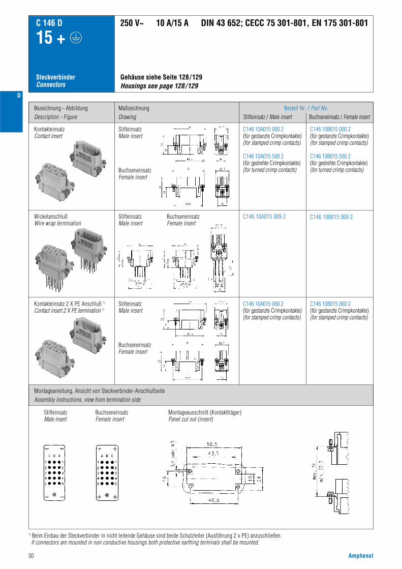
30 Amphenol
D
Bezeichnung - AbbildungDescription - Figure
Montageanleitung, Ansicht von Steckverbinder-AnschlußseiteAssembly instructions, view from termination side
MaßzeichnungDrawing
Bestell Nr. / Part No.Stifteinsatz / Male insert Buchseneinsatz / Female insert
C146 10A015 000 2(für gestanzte Crimpkontakte)(for stamped crimp contacts)
C146 10A015 500 2(für gedrehte Crimpkontakte)(for turned crimp contacts)
C146 10A015 060 2(für gestanzte Crimpkontakte)(for stamped crimp contacts)
C146 10B015 000 2(für gestanzte Crimpkontakte)(for stamped crimp contacts)
C146 10B015 500 2(für gedrehte Crimpkontakte)(for turned crimp contacts)
C146 10B015 060 2(für gestanzte Crimpkontakte)(for stamped crimp contacts)
SteckverbinderConnectors
C 146 D
15 +
KontakteinsatzContact insert
C146 10A015 009 2 C146 10B015 009 2
Gehäuse siehe Seite 128/129 Housings see page 128/129
250 V~ 10 A/15 A DIN 43 652; CECC 75 301-801, EN 175 301-801
Kontakteinsatz 2 X PE Anschluß 1)
Contact insert 2 X PE termination 1)
StifteinsatzMale insert
BuchseneinsatzFemale insert
StifteinsatzMale insert
StifteinsatzMale insert
BuchseneinsatzFemale insert
BuchseneinsatzFemale insert
StifteinsatzMale insert
BuchseneinsatzFemale insert
Montageausschnitt (Kontaktträger)Panel cut out (insert)
1) Beim Einbau der Steckverbinder in nicht leitende Gehäuse sind beide Schutzleiter (Ausführung 2 x PE) anzuschließen.If connectors are mounted in non conductive housings both protective earthing terminals shall be mounted.
WickelanschlußWire wrap termination

Amphenol 31
D
LieferformSupplied as
Gestanzte Einzelkontakte / Stamped single contacts
für Leiterquerschnittfor wire gauge
AWG StückzahlPieces
Bestell Nr. 1) / Part No. 1)
Stiftkontakt / Male contact Buchsenkontakt / Female contact
C 146 D
15 +
CrimpkontakteCrimp contacts
StandardHochstromHigh current
StandardHochstromHigh current
StandardHochstromHigh current
StandardHochstromHigh current
0,14 - 0,5 mm2
0,5 - 1,5 mm2
1,5 - 2,5 mm2
0,5 - 1,5 mm2
1,5 - 2,5 mm2
0,14 - 0,5 mm2
0,5 - 1,5 mm2
1,5 - 2,5 mm2
0,5 - 1,5 mm2
1,5 - 2,5 mm2
0,14 - 0,5 mm2
0,5 - 1,5 mm2
1,5 - 2,5 mm2
0,5 - 1,5 mm2
1,5 - 2,5 mm2
0,14 - 0,5 mm2
0,5 - 1,5 mm2
1,5 - 2,5 mm2
0,5 - 1,5 mm2
1,5 - 2,5 mm2
26 - 2020 - 1616 - 1420 - 1616 - 14
26 - 2020 - 1616 - 1420 - 1616 - 14
26 - 2020 - 1616 - 1420 - 1616 - 1426 - 2020 - 1616 - 1420 - 1618 - 14
200200100200100
100100100100100
2000200020002000200020002000200020002000
VN01 016 0003 (1)VN01 016 0002 (1)VN01 016 0005 (1)VN01 016 0015 1VN01 016 0016 1
ZN01 016 0003 (1)ZN01 016 0002 (1)ZN01 016 0005 (1)ZN01 016 0015 (1)ZN01 016 0016 (1)
HN01 016 0003 (1)HN01 016 0002 (1)HN01 016 0005 (1)HN01 016 0015 (1)HN01 016 0016 (1)TN01 016 0003 (1)TN01 016 0002 (1)TN01 016 0005 (1)TN01 016 0015 (1)TN01 016 0016 (1)
ZN02 016 0003 (1)ZN02 016 0002 (1)ZN02 016 0005 (1)ZN02 016 0015 (1)ZN02 016 0016 (1)
VN02 016 0003 (1)VN02 016 0002 (1)VN02 016 0005 (1)VN02 016 0015 1VN02 016 0016 1
HN02 016 0003 (1)HN02 016 0002 (1)HN02 016 0005 (1)HN02 016 0015 (1)HN02 016 0016 (1)TN02 016 0003 (1)TN02 016 0002 (1)TN02 016 0005 (1)TN02 016 0015 (1)TN02 016 0016 (1)
Kontaktzuführung rechtsContact feeding right hand side
Gestanzte Bandkontakte für Crimpmaschinen / Stamped contacts on reel for crimp machines
Gestanzte Bandkontakte für Crimpzangen / Stamped Contacts on reel for hand crimp tools
Kontaktzuführung linksContact feeding left hand side
1) Erläuterung der Bestell-Nr. für die Kontakte siehe Seite 41) Explanation of the Part No. for contacts see page 4
Gestanzte Bandkontakte für CrimpmaschinenStamped contacts on reel for crimp machines
200 / 100 Stück
200 / 100 pcs
2000 Stück(Zuführung links)
2000 pcs(feeding lefthand side)
0,14 - 0,37 mm2
0,5 mm2
0,75 - 1,0 mm2
1,5 mm2
2,5 mm2
26 - 222020 - 1616 - 1514
100100100100100
VN01 016 0024 1CVN01 016 0025 1CVN01 016 0026 1CVN01 016 0027 1CVN01 016 0028 1C
VN02 016 0024 1CVN02 016 0025 1CVN02 016 0026 1CVN02 016 0027 1CVN02 016 0028 1C
Gedrehte Crimpkontakte / Turned crimp contacts
Derating Kurven / Derating curves
EinzelkontaktSingle contact
Gestanzte EinzelkontakteStamped single contacts
Gestanzte Bandkontakte für CrimpzangenStamped contacts on reel for hand crimping tools
Gedrehte EinzelkontakteTurned single contacts
Kurve / Curveabcde
Kontakt / ContactStandard gestanztStandard stamped
Hochstrom gestanztHigh current, stamped
Querschnitt / Wire gauge0,5 mm2
1,5 mm2
2,5 mm2
1,5 mm2
2,5 mm2
Kurve / Curveabc
Kontakt / ContactStandard gedrehtStandard turned
Querschnitt / Wire gauge0,5 mm2
1,5 mm2
2,5 mm2
Stro
mbe
last
bark
eit I
(A)
Curre
nt c
arry
ing
capa
city
I (A
)
Bauelement Umgebungstemperatur Tu (°C)Ambient temperature Tamb (°C)
Gestanzte KontakteStamped contacts
Stro
mbe
last
bark
eit I
(A)
Curre
nt c
arry
ing
capa
city
I (A
)
Bauelement Umgebungstemperatur Tu (°C)Ambient temperature Tamb (°C)
Gedrehte KontakteTurned contacts
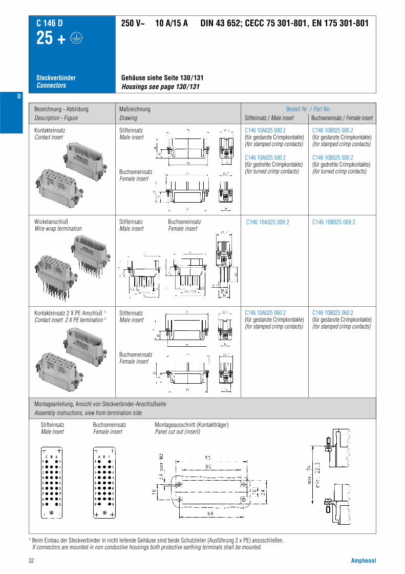
32 Amphenol
D
Bezeichnung - AbbildungDescription - Figure
Montageanleitung, Ansicht von Steckverbinder-AnschlußseiteAssembly instructions, view from termination side
MaßzeichnungDrawing
Bestell Nr. / Part No.Stifteinsatz / Male insert Buchseneinsatz / Female insert
C146 10A025 000 2(für gestanzte Crimpkontakte)(for stamped crimp contacts)
C146 10A025 500 2(für gedrehte Crimpkontakte)(for turned crimp contacts)
C146 10B025 000 2(für gestanzte Crimpkontakte)(for stamped crimp contacts)
C146 10B025 500 2(für gedrehte Crimpkontakte)(for turned crimp contacts)
SteckverbinderConnectors
C 146 D
25 +
KontakteinsatzContact insert
C146 10A025 009 2 C146 10B025 009 2
C146 10A025 060 2(für gestanzte Crimpkontakte)(for stamped crimp contacts)
C146 10B025 060 2(für gestanzte Crimpkontakte)(for stamped crimp contacts)
Gehäuse siehe Seite 130/131 Housings see page 130/131
250 V~ 10 A/15 A DIN 43 652; CECC 75 301-801, EN 175 301-801
Kontakteinsatz 2 X PE Anschluß 1)
Contact insert 2 X PE termination 1)
StifteinsatzMale insert
BuchseneinsatzFemale insert
StifteinsatzMale insert
BuchseneinsatzFemale insert
StifteinsatzMale insert
BuchseneinsatzFemale insert
StifteinsatzMale insert
BuchseneinsatzFemale insert
Montageausschnitt (Kontaktträger)Panel cut out (insert)
WickelanschlußWire wrap termination
1) Beim Einbau der Steckverbinder in nicht leitende Gehäuse sind beide Schutzleiter (Ausführung 2 x PE) anzuschließen.If connectors are mounted in non conductive housings both protective earthing terminals shall be mounted.

Amphenol 33
D
LieferformSupplied as
Gestanzte Einzelkontakte / Stamped single contacts
für Leiterquerschnittfor wire gauge
AWG StückzahlPieces
Bestell Nr. 1) / Part No. 1)
Stiftkontakt / Male contact Buchsenkontakt / Female contact
C 146 D
25 +
CrimpkontakteCrimp contacts
StandardHochstromHigh current
StandardHochstromHigh current
StandardHochstromHigh current
StandardHochstromHigh current
0,14 - 0,5 mm2
0,5 - 1,5 mm2
1,5 - 2,5 mm2
0,5 - 1,5 mm2
1,5 - 2,5 mm2
0,14 - 0,5 mm2
0,5 - 1,5 mm2
1,5 - 2,5 mm2
0,5 - 1,5 mm2
1,5 - 2,5 mm2
0,14 - 0,5 mm2
0,5 - 1,5 mm2
1,5 - 2,5 mm2
0,5 - 1,5 mm2
1,5 - 2,5 mm2
0,14 - 0,5 mm2
0,5 - 1,5 mm2
1,5 - 2,5 mm2
0,5 - 1,5 mm2
1,5 - 2,5 mm2
26 - 2020 - 1616 - 1420 - 1616 - 14
26 - 2020 - 1616 - 1420 - 1616 - 14
26 - 2020 - 1616 - 1420 - 1616 - 1426 - 2020 - 1616 - 1420 - 1618 - 14
200200100200100
100100100100100
2000200020002000200020002000200020002000
VN01 016 0003 (1)VN01 016 0002 (1)VN01 016 0005 (1)VN01 016 0015 1VN01 016 0016 1
ZN01 016 0003 (1)ZN01 016 0002 (1)ZN01 016 0005 (1)ZN01 016 0015 (1)ZN01 016 0016 (1)
HN01 016 0003 (1)HN01 016 0002 (1)HN01 016 0005 (1)HN01 016 0015 (1)HN01 016 0016 (1)TN01 016 0003 (1)TN01 016 0002 (1)TN01 016 0005 (1)TN01 016 0015 (1)TN01 016 0016 (1)
ZN02 016 0003 (1)ZN02 016 0002 (1)ZN02 016 0005 (1)ZN02 016 0015 (1)ZN02 016 0016 (1)
VN02 016 0003 (1)VN02 016 0002 (1)VN02 016 0005 (1)VN02 016 0015 1VN02 016 0016 1
HN02 016 0003 (1)HN02 016 0002 (1)HN02 016 0005 (1)HN02 016 0015 (1)HN02 016 0016 (1)TN02 016 0003 (1)TN02 016 0002 (1)TN02 016 0005 (1)TN02 016 0015 (1)TN02 016 0016 (1)
Kontaktzuführung rechtsContact feeding right hand side
Gestanzte Bandkontakte für Crimpmaschinen / Stamped contacts on reel for crimp machines
Gestanzte Bandkontakte für Crimpzangen / Stamped contacts on reel for hand crimp tools
Kontaktzuführung linksContact feeding left hand side
1) Erläuterung der Bestell-Nr. für die Kontakte siehe Seite 41) Explanation of the Part No. for contacts see page 4
Gestanzte EinzelkontakteStamped single contacts
Gestanzte Bandkontakte für CrimpzangenStamped contacts on reel for hand crimping tools
Gestanzte Bandkontakte für CrimpmaschinenStamped contacts on reel for crimp machines
200 / 100 Stück
200 / 100 pcs
2000 Stück(Zuführung links)
2000 pcs(feeding lefthand side)
0,14 - 0,37 mm2
0,5 mm2
0,75 - 1,0 mm2
1,5 mm2
2,5 mm2
26 - 222020 - 1616 - 1514
100100100100100
VN01 016 0024 1CVN01 016 0025 1CVN01 016 0026 1CVN01 016 0027 1CVN01 016 0028 1C
VN02 016 0024 1CVN02 016 0025 1CVN02 016 0026 1CVN02 016 0027 1CVN02 016 0028 1C
Gedrehte Crimpkontakte / Turned crimp contacts
Derating Kurven / Derating curves
EinzelkontaktSingle contact
Gedrehte EinzelkontakteTurned single contacts
Kurve / Curveabcde
Kontakt / ContactStandard gestanztStandard stamped
Hochstrom gestanztHigh current, stamped
Querschnitt / Wire gauge0,5 mm2
1,5 mm2
2,5 mm2
1,5 mm2
2,5 mm2
Kurve / Curveabc
Kontakt / ContactStandard gedrehtStandard turned
Querschnitt / Wire gauge0,5 mm2
1,5 mm2
2,5 mm2
Stro
mbe
last
bark
eit I
(A)
Curre
nt c
arry
ing
capa
city
I (A
)
Bauelement Umgebungstemperatur Tu (°C)Ambient temperature Tamb (°C)
Gestanzte KontakteStamped contacts
Stro
mbe
last
bark
eit I
(A)
Curre
nt c
arry
ing
capa
city
I (A
)
Bauelement Umgebungstemperatur Tu (°C)Ambient temperature Tamb (°C)
Gedrehte KontakteTurned contacts
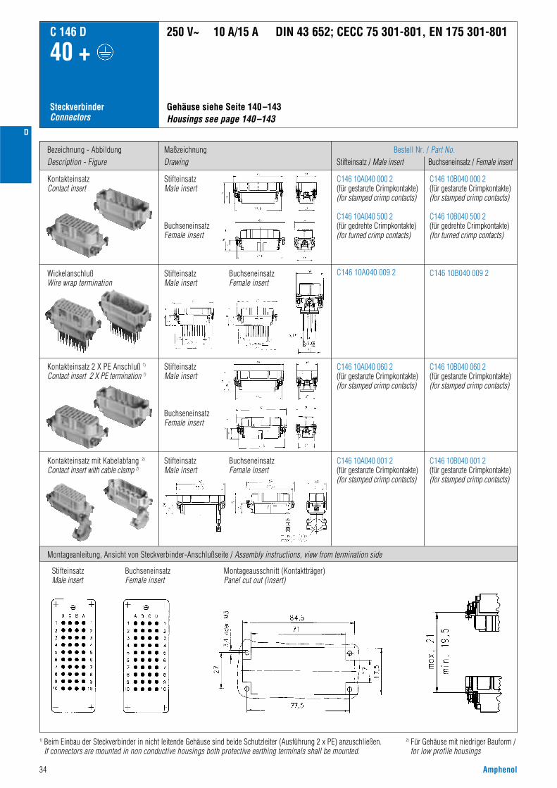
34 Amphenol
D
Bezeichnung - AbbildungDescription - Figure
MaßzeichnungDrawing
Bestell Nr. / Part No.Stifteinsatz / Male insert Buchseneinsatz / Female insert
C146 10A040 000 2(für gestanzte Crimpkontakte)(for stamped crimp contacts)
C146 10A040 500 2(für gedrehte Crimpkontakte)(for turned crimp contacts)
C146 10B040 000 2(für gestanzte Crimpkontakte)(for stamped crimp contacts)
C146 10B040 500 2(für gedrehte Crimpkontakte) (for turned crimp contacts)
C146 10A040 060 2(für gestanzte Crimpkontakte)(for stamped crimp contacts)
C146 10B040 060 2(für gestanzte Crimpkontakte)(for stamped crimp contacts)
SteckverbinderConnectors
C 146 D
40 +
KontakteinsatzContact insert
C146 10A040 001 2(für gestanzte Crimpkontakte)(for stamped crimp contacts)
C146 10B040 001 2(für gestanzte Crimpkontakte)(for stamped crimp contacts)
Kontakteinsatz mit Kabelabfang 2)
Contact insert with cable clamp 2)
C146 10A040 009 2 C146 10B040 009 2
Gehäuse siehe Seite 140–143Housings see page 140–143
250 V~ 10 A/15 A DIN 43 652; CECC 75 301-801, EN 175 301-801
Montageanleitung, Ansicht von Steckverbinder-Anschlußseite / Assembly instructions, view from termination side
Kontakteinsatz 2 X PE Anschluß 1)
Contact insert 2 X PE termination 1)
StifteinsatzMale insert
BuchseneinsatzFemale insert
StifteinsatzMale insert
BuchseneinsatzFemale insert
StifteinsatzMale insert
BuchseneinsatzFemale insert
StifteinsatzMale insert
BuchseneinsatzFemale insert
StifteinsatzMale insert
BuchseneinsatzFemale insert
Montageausschnitt (Kontaktträger)Panel cut out (insert)
WickelanschlußWire wrap termination
2) Für Gehäuse mit niedriger Bauform /for low profile housings
1) Beim Einbau der Steckverbinder in nicht leitende Gehäuse sind beide Schutzleiter (Ausführung 2 x PE) anzuschließen.If connectors are mounted in non conductive housings both protective earthing terminals shall be mounted.

Amphenol 35
D
LieferformSupplied as
Gestanzte Einzelkontakte / Stamped single contacts
für Leiterquerschnittfor wire gauge
AWG StückzahlPieces
Bestell Nr. 1) / Part No. 1)
Stiftkontakt / Male contact Buchsenkontakt / Female contact
C 146 D
40 +
CrimpkontakteCrimp contacts
StandardHochstromHigh current
StandardHochstromHigh current
StandardHochstromHigh current
StandardHochstromHigh current
0,14 - 0,5 mm2
0,5 - 1,5 mm2
1,5 - 2,5 mm2
0,5 - 1,5 mm2
1,5 - 2,5 mm2
0,14 - 0,5 mm2
0,5 - 1,5 mm2
1,5 - 2,5 mm2
0,5 - 1,5 mm2
1,5 - 2,5 mm2
0,14 - 0,5 mm2
0,5 - 1,5 mm2
1,5 - 2,5 mm2
0,5 - 1,5 mm2
1,5 - 2,5 mm2
0,14 - 0,5 mm2
0,5 - 1,5 mm2
1,5 - 2,5 mm2
0,5 - 1,5 mm2
1,5 - 2,5 mm2
26 - 2020 - 1616 - 1420 - 1616 - 14
26 - 2020 - 1616 - 1420 - 1616 - 14
26 - 2020 - 1616 - 1420 - 1616 - 1426 - 2020 - 1616 - 1420 - 1618 - 14
200200100200100
100100100100100
2000200020002000200020002000200020002000
VN01 016 0003 (1)VN01 016 0002 (1)VN01 016 0005 (1)VN01 016 0015 1VN01 016 0016 1
ZN01 016 0003 (1)ZN01 016 0002 (1)ZN01 016 0005 (1)ZN01 016 0015 (1)ZN01 016 0016 (1)
HN01 016 0003 (1)HN01 016 0002 (1)HN01 016 0005 (1)HN01 016 0015 (1)HN01 016 0016 (1)TN01 016 0003 (1)TN01 016 0002 (1)TN01 016 0005 (1)TN01 016 0015 (1)TN01 016 0016 (1)
ZN02 016 0003 (1)ZN02 016 0002 (1)ZN02 016 0005 (1)ZN02 016 0015 (1)ZN02 016 0016 (1)
VN02 016 0003 (1)VN02 016 0002 (1)VN02 016 0005 (1)VN02 016 0015 1VN02 016 0016 1
HN02 016 0003 (1)HN02 016 0002 (1)HN02 016 0005 (1)HN02 016 0015 (1)HN02 016 0016 (1)TN02 016 0003 (1)TN02 016 0002 (1)TN02 016 0005 (1)TN02 016 0015 (1)TN02 016 0016 (1)
Kontaktzuführung rechtsContact feeding right hand side
Gestanzte Bandkontakte für Crimpmaschinen / Stamped contacts on reel for crimp machines
Gestanzte Bandkontakte für Crimpzangen / Stamped contacts on reel for hand crimp tools
Kontaktzuführung linksContact feeding left hand side
1) Erläuterung der Bestell-Nr. für die Kontakte siehe Seite 41) Explanation of the Part No. for contacts see page 4
Gestanzte EinzelkontakteStamped single contacts
Gestanzte Bandkontakte für CrimpzangenStamped contacts on reel for hand crimping tools
Gestanzte Bandkontakte für CrimpmaschinenStamped contacts on reel for crimp machines
200 / 100 Stück
200 / 100 pcs
2000 Stück(Zuführung links)
2000 pcs(feeding lefthand side)
0,14 - 0,37 mm2
0,5 mm2
0,75 - 1,0 mm2
1,5 mm2
2,5 mm2
26 - 222020 - 1616 - 1514
100100100100100
VN01 016 0024 1CVN01 016 0025 1CVN01 016 0026 1CVN01 016 0027 1CVN01 016 0028 1C
VN02 016 0024 1CVN02 016 0025 1CVN02 016 0026 1CVN02 016 0027 1CVN02 016 0028 1C
Gedrehte Crimpkontakte / Turned crimp contacts
Derating Kurven / Derating curves
EinzelkontaktSingle contact
Gedrehte EinzelkontakteTurned single contacts
Kurve / Curveabcde
Kontakt / ContactStandard gestanztStandard stamped
Hochstrom gestanztHigh current, stamped
Querschnitt / Wire gauge0,5 mm2
1,5 mm2
2,5 mm2
1,5 mm2
2,5 mm2
Kurve / Curveabc
Kontakt / ContactStandard gedrehtStandard turned
Querschnitt / Wire gauge0,5 mm2
1,5 mm2
2,5 mm2
Stro
mbe
last
bark
eit I
(A)
Curre
nt c
arry
ing
capa
city
I (A
)
Bauelement Umgebungstemperatur Tu (°C)
Gestanzte KontakteStamped contacts
Stro
mbe
last
bark
eit I
(A)
Curre
nt c
arry
ing
capa
city
I (A
)
Bauelement Umgebungstemperatur Tu (°C)Ambient temperature Tamb (°C)
Gedrehte KontakteTurned contacts
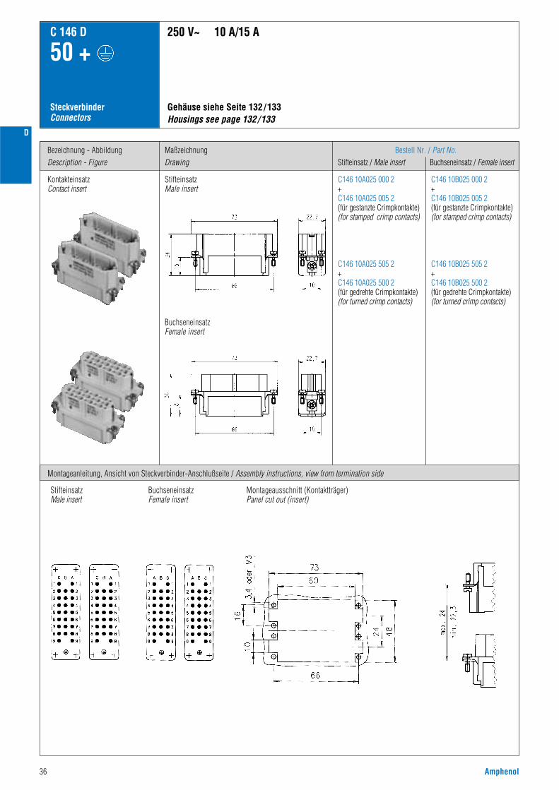
D
36 Amphenol
Bezeichnung - AbbildungDescription - Figure
MaßzeichnungDrawing
Bestell Nr. / Part No.Stifteinsatz / Male insert Buchseneinsatz / Female insert
C146 10A025 000 2+C146 10A025 005 2(für gestanzte Crimpkontakte)(for stamped crimp contacts)
C146 10A025 505 2+C146 10A025 500 2(für gedrehte Crimpkontakte)(for turned crimp contacts)
C146 10B025 000 2+C146 10B025 005 2(für gestanzte Crimpkontakte)(for stamped crimp contacts)
C146 10B025 505 2+C146 10B025 500 2(für gedrehte Crimpkontakte)(for turned crimp contacts)
SteckverbinderConnectors
C 146 D
50 +
KontakteinsatzContact insert
Gehäuse siehe Seite 132/133 Housings see page 132/133
250 V~ 10 A/15 A
Montageanleitung, Ansicht von Steckverbinder-Anschlußseite / Assembly instructions, view from termination side
StifteinsatzMale insert
BuchseneinsatzFemale insert
StifteinsatzMale insert
BuchseneinsatzFemale insert
Montageausschnitt (Kontaktträger)Panel cut out (insert)

Amphenol 37
D
LieferformSupplied as
Gestanzte Einzelkontakte / Stamped single contacts
für Leiterquerschnittfor wire gauge
AWG StückzahlPieces
Bestell Nr. 1) / Part No. 1)
Stiftkontakt / Male contact Buchsenkontakt / Female contact
C 146 D
50 +
CrimpkontakteCrimp contacts
StandardHochstromHigh current
StandardHochstromHigh current
StandardHochstromHigh current
StandardHochstromHigh current
0,14 - 0,5 mm2
0,5 - 1,5 mm2
1,5 - 2,5 mm2
0,5 - 1,5 mm2
1,5 - 2,5 mm2
0,14 - 0,5 mm2
0,5 - 1,5 mm2
1,5 - 2,5 mm2
0,5 - 1,5 mm2
1,5 - 2,5 mm2
0,14 - 0,5 mm2
0,5 - 1,5 mm2
1,5 - 2,5 mm2
0,5 - 1,5 mm2
1,5 - 2,5 mm2
0,14 - 0,5 mm2
0,5 - 1,5 mm2
1,5 - 2,5 mm2
0,5 - 1,5 mm2
1,5 - 2,5 mm2
26 - 2020 - 1616 - 1420 - 1616 - 14
26 - 2020 - 1616 - 1420 - 1616 - 14
26 - 2020 - 1616 - 1420 - 1616 - 1426 - 2020 - 1616 - 1420 - 1618 - 14
200200100200100
100100100100100
2000200020002000200020002000200020002000
VN01 016 0003 (1)VN01 016 0002 (1)VN01 016 0005 (1)VN01 016 0015 1VN01 016 0016 1
ZN01 016 0003 (1)ZN01 016 0002 (1)ZN01 016 0005 (1)ZN01 016 0015 (1)ZN01 016 0016 (1)
HN01 016 0003 (1)HN01 016 0002 (1)HN01 016 0005 (1)HN01 016 0015 (1)HN01 016 0016 (1)TN01 016 0003 (1)TN01 016 0002 (1)TN01 016 0005 (1)TN01 016 0015 (1)TN01 016 0016 (1)
ZN02 016 0003 (1)ZN02 016 0002 (1)ZN02 016 0005 (1)ZN02 016 0015 (1)ZN02 016 0016 (1)
VN02 016 0003 (1)VN02 016 0002 (1)VN02 016 0005 (1)VN02 016 0015 1VN02 016 0016 1
HN02 016 0003 (1)HN02 016 0002 (1)HN02 016 0005 (1)HN02 016 0015 (1)HN02 016 0016 (1)TN02 016 0003 (1)TN02 016 0002 (1)TN02 016 0005 (1)TN02 016 0015 (1)TN02 016 0016 (1)
Kontaktzuführung rechtsContact feeding right hand side
Gestanzte Bandkontakte für Crimpmaschinen / Stamped contacts on reel for crimp machines
Gestanzte Bandkontakte für Crimpzangen / Stamped contacts on reel for hand crimp tools
Kontaktzuführung linksContact feeding left hand side
1) Erläuterung der Bestell-Nr. für die Kontakte siehe Seite 41) Explanation of the Part No. for contacts see page 4
Gestanzte EinzelkontakteStamped single contacts
Gestanzte Bandkontakte für CrimpzangenStamped contacts on reel for hand crimping tools
Gestanzte Bandkontakte für CrimpmaschinenStamped contacts on reel for crimp machines
200 / 100 Stück
200 / 100 pcs
2000 Stück(Zuführung links)
2000 pcs(feeding lefthand side)
0,14 - 0,37 mm2
0,5 mm2
0,75 - 1,0 mm2
1,5 mm2
2,5 mm2
26 - 222020 - 1616 - 1514
100100100100100
VN01 016 0024 1CVN01 016 0025 1CVN01 016 0026 1CVN01 016 0027 1CVN01 016 0028 1C
VN02 016 0024 1CVN02 016 0025 1CVN02 016 0026 1CVN02 016 0027 1CVN02 016 0028 1C
Gedrehte Crimpkontakte / Turned crimp contacts
Derating Kurven / Derating curves
EinzelkontaktSingle contact
Gedrehte EinzelkontakteTurned single contacts
Kurve / Curveabcde
Kontakt / ContactStandard gestanztStandard stamped
Hochstrom gestanztHigh current, stamped
Querschnitt / Wire gauge0,5 mm2
1,5 mm2
2,5 mm2
1,5 mm2
2,5 mm2
Kurve / Curveabc
Kontakt / ContactStandard gedrehtStandard turned
Querschnitt / Wire gauge0,5 mm2
1,5 mm2
2,5 mm2
Stro
mbe
last
bark
eit I
(A)
Curre
nt c
arry
ing
capa
city
I (A
)
Bauelement Umgebungstemperatur Tu (°C)Ambient temperature Tamb (°C)
Gestanzte KontakteStamped contacts
Stro
mbe
last
bark
eit I
(A)
Curre
nt c
arry
ing
capa
city
I (A
)
Bauelement Umgebungstemperatur Tu (°C)Ambient temperature Tamb (°C)
Gedrehte KontakteTurned contacts
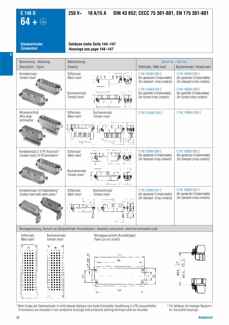
38 Amphenol
D
Bezeichnung - AbbildungDescription - Figure
MaßzeichnungDrawing
Bestell Nr. / Part No.Stifteinsatz / Male insert Buchseneinsatz / Female insert
C146 10A064 000 2(für gestanzte Crimpkontakte)(for stamped crimp contacts)
C146 10A064 500 2(für gedrehte Crimpkontakte)(for turned crimp contacts)
C146 10B064 000 2(für gestanzte Crimpkontakte)(for stamped crimp contacts)
C146 10B064 500 2(für gedrehte Crimpkontakte)(for turned crimp contacts)
C146 10A064 060 2(für gestanzte Crimpkontakte)(for stamped crimp contacts)
C146 10B064 060 2(für gestanzte Crimpkontakte)(for stamped crimp contacts)
SteckverbinderConnectors
C 146 D
64 +
C146 10A064 001 2(für gestanzte Crimpkontakte)(for stamped crimp contacts)
C146 10B064 001 2(für gestanzte Crimpkontakte)(for stamped crimp contacts)
Kontakteinsatz mit Kabelabfang 2)
Contact insert with cable clamp 2)
C146 10A064 009 2 C146 10B064 009 2
Gehäuse siehe Seite 144–147 Housings see page 144–147
250 V~ 10 A/15 A DIN 43 652; CECC 75 301-801, EN 175 301-801
Montageanleitung, Ansicht von Steckverbinder-Anschlußseite / Assembly instructions, view from termination side
Kontakteinsatz 2 X PE Anschluß 1)
Contact insert 2 X PE termination 1)
StifteinsatzMale insert
BuchseneinsatzFemale insert
BuchseneinsatzFemale insert
StifteinsatzMale insert
BuchseneinsatzFemale insert
StifteinsatzMale insert
StifteinsatzMale insert
BuchseneinsatzFemale insert
StifteinsatzMale insert
BuchseneinsatzFemale insert
Montageausschnitt (Kontaktträger)Panel cut out (insert)
KontakteinsatzContact insert
WickelanschlußWire wraptermination
2) Für Gehäuse mit niedriger Bauform /for low profile housings
1) Beim Einbau der Steckverbinder in nicht leitende Gehäuse sind beide Schutzleiter (Ausführung 2 x PE) anzuschließen.If connectors are mounted in non conductive housings both protective earthing terminals shall be mounted.

Amphenol 39
D
LieferformSupplied as
Gestanzte Einzelkontakte / Stamped single contacts
für Leiterquerschnittfor wire gauge
AWG StückzahlPieces
Bestell Nr. 1) / Part No. 1)
Stiftkontakt / Male contact Buchsenkontakt / Female contact
C 146 D
64 +
CrimpkontakteCrimp contacts
StandardHochstromHigh current
StandardHochstromHigh current
StandardHochstromHigh current
StandardHochstromHigh current
0,14 - 0,5 mm2
0,5 - 1,5 mm2
1,5 - 2,5 mm2
0,5 - 1,5 mm2
1,5 - 2,5 mm2
0,14 - 0,5 mm2
0,5 - 1,5 mm2
1,5 - 2,5 mm2
0,5 - 1,5 mm2
1,5 - 2,5 mm2
0,14 - 0,5 mm2
0,5 - 1,5 mm2
1,5 - 2,5 mm2
0,5 - 1,5 mm2
1,5 - 2,5 mm2
0,14 - 0,5 mm2
0,5 - 1,5 mm2
1,5 - 2,5 mm2
0,5 - 1,5 mm2
1,5 - 2,5 mm2
26 - 2020 - 1616 - 1420 - 1616 - 14
26 - 2020 - 1616 - 1420 - 1616 - 14
26 - 2020 - 1616 - 1420 - 1616 - 1426 - 2020 - 1616 - 1420 - 1618 - 14
200200100200100
100100100100100
2000200020002000200020002000200020002000
VN01 016 0003 (1)VN01 016 0002 (1)VN01 016 0005 (1)VN01 016 0015 1VN01 016 0016 1
ZN01 016 0003 (1)ZN01 016 0002 (1)ZN01 016 0005 (1)ZN01 016 0015 (1)ZN01 016 0016 (1)
HN01 016 0003 (1)HN01 016 0002 (1)HN01 016 0005 (1)HN01 016 0015 (1)HN01 016 0016 (1)TN01 016 0003 (1)TN01 016 0002 (1)TN01 016 0005 (1)TN01 016 0015 (1)TN01 016 0016 (1)
ZN02 016 0003 (1)ZN02 016 0002 (1)ZN02 016 0005 (1)ZN02 016 0015 (1)ZN02 016 0016 (1)
VN02 016 0003 (1)VN02 016 0002 (1)VN02 016 0005 (1)VN02 016 0015 1VN02 016 0016 1
HN02 016 0003 (1)HN02 016 0002 (1)HN02 016 0005 (1)HN02 016 0015 (1)HN02 016 0016 (1)TN02 016 0003 (1)TN02 016 0002 (1)TN02 016 0005 (1)TN02 016 0015 (1)TN02 016 0016 (1)
Kontaktzuführung rechtsContact feeding right hand side
Gestanzte Bandkontakte für Crimpmaschinen / Stamped contacts on reel for crimp machines
Gestanzte Bandkontakte für Crimpzangen / Stamped contacts on reel for hand crimp tools
Kontaktzuführung linksContact feeding left hand side
1) Erläuterung der Bestell-Nr. für die Kontakte siehe Seite 41) Explanation of the Part No. for contacts see page 4
Gestanzte EinzelkontakteStamped single contacts
Gestanzte Bandkontakte für CrimpzangenStamped contacts on reel for hand crimping tools
Gestanzte Bandkontakte für CrimpmaschinenStamped contacts on reel for crimp machines
200 / 100 Stück
200 / 100 pcs
2000 Stück(Zuführung links)
2000 pcs(feeding lefthand side)
0,14 - 0,37 mm2
0,5 mm2
0,75 - 1,0 mm2
1,5 mm2
2,5 mm2
26 - 222020 - 1616 - 1514
100100100100100
VN01 016 0024 1CVN01 016 0025 1CVN01 016 0026 1CVN01 016 0027 1CVN01 016 0028 1C
VN02 016 0024 1CVN02 016 0025 1CVN02 016 0026 1CVN02 016 0027 1CVN02 016 0028 1C
Gedrehte Crimpkontakte / Turned crimp contacts
Derating Kurven / Derating curves
EinzelkontaktSingle contact
Gedrehte EinzelkontakteTurned single contacts
Kurve / Curveabcde
Kontakt / ContactStandard gestanztStandard stamped
Hochstrom gestanztHigh current, stamped
Querschnitt / Wire gauge0,5 mm2
1,5 mm2
2,5 mm2
1,5 mm2
2,5 mm2
Kurve / Curveabc
Kontakt / ContactStandard gedrehtStandard turned
Querschnitt / Wire gauge0,5 mm2
1,5 mm2
2,5 mm2
Stro
mbe
last
bark
eit I
(A)
Curre
nt c
arry
ing
capa
city
I (A
)
Bauelement Umgebungstemperatur Tu (°C)Ambient temperature Tamb (°C)
Gestanzte KontakteStamped contacts
Stro
mbe
last
bark
eit I
(A)
Curre
nt c
arry
ing
capa
city
I (A
)
Bauelement Umgebungstemperatur Tu (°C)Ambient temperature Tamb (°C)
Gedrehte KontakteTurned contacts

40 Amphenol
D
Bezeichnung - AbbildungDescription - Figure
MaßzeichnungDrawing
Bestell Nr. / Part No.Stifteinsatz / Male insert Buchseneinsatz / Female insert
C146 10A064 000 2+C146 10A064 005 2(für gestanzte Crimpkontakte)(for stamped crimp contacts)
C146 10A064 500 2+C146 10A064 505 2(für gedrehte Crimpkontakte)(for turned crimp contacts)
C146 10B064 000 2+C146 10B064 005 2(für gestanzte Crimpkontakte)(for stamped crimp contacts)
C146 10B064 500 2+C146 10B064 505 2(für gedrehte Crimpkontakte)(for turned crimp contacts)
SteckverbinderConnectors
C 146 D
128 +
KontakteinsatzContact insert
Gehäuse siehe Seite 148/149 Housings see page 148/149
250 V~ 10 A/15 A
Montageanleitung, Ansicht von Steckverbinder-Anschlußseite / Assembly instructions, view from termination side
StifteinsatzMale insert
BuchseneinsatzFemale insert
StifteinsatzMale insert
BuchseneinsatzFemale insert
Montageausschnitt (Kontaktträger)Panel cut out (insert)
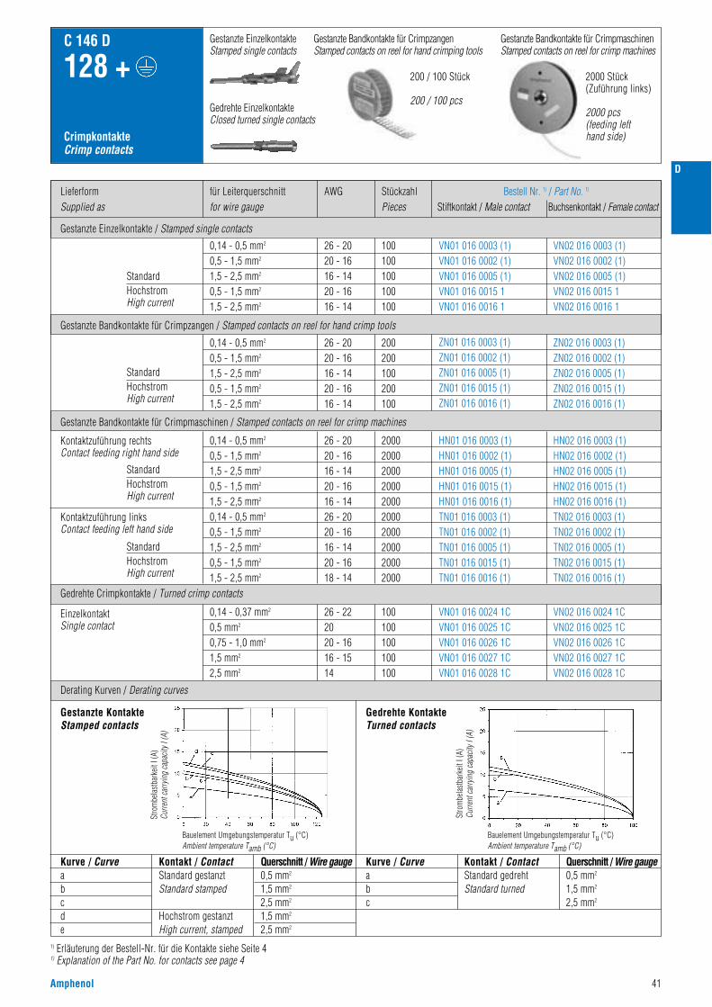
Amphenol 41
D
LieferformSupplied as
Gestanzte Einzelkontakte / Stamped single contacts
für Leiterquerschnittfor wire gauge
AWG StückzahlPieces
Bestell Nr. 1) / Part No. 1)
Stiftkontakt / Male contact Buchsenkontakt / Female contact
C 146 D
128 +
CrimpkontakteCrimp contacts
StandardHochstromHigh current
StandardHochstromHigh current
StandardHochstromHigh current
StandardHochstromHigh current
0,14 - 0,5 mm2
0,5 - 1,5 mm2
1,5 - 2,5 mm2
0,5 - 1,5 mm2
1,5 - 2,5 mm2
0,14 - 0,5 mm2
0,5 - 1,5 mm2
1,5 - 2,5 mm2
0,5 - 1,5 mm2
1,5 - 2,5 mm2
0,14 - 0,5 mm2
0,5 - 1,5 mm2
1,5 - 2,5 mm2
0,5 - 1,5 mm2
1,5 - 2,5 mm2
0,14 - 0,5 mm2
0,5 - 1,5 mm2
1,5 - 2,5 mm2
0,5 - 1,5 mm2
1,5 - 2,5 mm2
26 - 2020 - 1616 - 1420 - 1616 - 14
26 - 2020 - 1616 - 1420 - 1616 - 14
26 - 2020 - 1616 - 1420 - 1616 - 1426 - 2020 - 1616 - 1420 - 1618 - 14
200200100200100
100100100100100
2000200020002000200020002000200020002000
VN01 016 0003 (1)VN01 016 0002 (1)VN01 016 0005 (1)VN01 016 0015 1VN01 016 0016 1
ZN01 016 0003 (1)ZN01 016 0002 (1)ZN01 016 0005 (1)ZN01 016 0015 (1)ZN01 016 0016 (1)
HN01 016 0003 (1)HN01 016 0002 (1)HN01 016 0005 (1)HN01 016 0015 (1)HN01 016 0016 (1)TN01 016 0003 (1)TN01 016 0002 (1)TN01 016 0005 (1)TN01 016 0015 (1)TN01 016 0016 (1)
ZN02 016 0003 (1)ZN02 016 0002 (1)ZN02 016 0005 (1)ZN02 016 0015 (1)ZN02 016 0016 (1)
VN02 016 0003 (1)VN02 016 0002 (1)VN02 016 0005 (1)VN02 016 0015 1VN02 016 0016 1
HN02 016 0003 (1)HN02 016 0002 (1)HN02 016 0005 (1)HN02 016 0015 (1)HN02 016 0016 (1)TN02 016 0003 (1)TN02 016 0002 (1)TN02 016 0005 (1)TN02 016 0015 (1)TN02 016 0016 (1)
Kontaktzuführung rechtsContact feeding right hand side
Gestanzte Bandkontakte für Crimpmaschinen / Stamped contacts on reel for crimp machines
Gestanzte Bandkontakte für Crimpzangen / Stamped contacts on reel for hand crimp tools
Kontaktzuführung linksContact feeding left hand side
1) Erläuterung der Bestell-Nr. für die Kontakte siehe Seite 41) Explanation of the Part No. for contacts see page 4
Gestanzte EinzelkontakteStamped single contacts
Gestanzte Bandkontakte für CrimpzangenStamped contacts on reel for hand crimping tools
Gestanzte Bandkontakte für CrimpmaschinenStamped contacts on reel for crimp machines
200 / 100 Stück
200 / 100 pcs
2000 Stück(Zuführung links)
2000 pcs(feeding lefthand side)
0,14 - 0,37 mm2
0,5 mm2
0,75 - 1,0 mm2
1,5 mm2
2,5 mm2
26 - 222020 - 1616 - 1514
100100100100100
VN01 016 0024 1CVN01 016 0025 1CVN01 016 0026 1CVN01 016 0027 1CVN01 016 0028 1C
VN02 016 0024 1CVN02 016 0025 1CVN02 016 0026 1CVN02 016 0027 1CVN02 016 0028 1C
Gedrehte Crimpkontakte / Turned crimp contacts
Derating Kurven / Derating curves
EinzelkontaktSingle contact
Gedrehte EinzelkontakteClosed turned single contacts
Kurve / Curveabcde
Kontakt / ContactStandard gestanztStandard stamped
Hochstrom gestanztHigh current, stamped
Querschnitt / Wire gauge0,5 mm2
1,5 mm2
2,5 mm2
1,5 mm2
2,5 mm2
Kurve / Curveabc
Kontakt / ContactStandard gedrehtStandard turned
Querschnitt / Wire gauge0,5 mm2
1,5 mm2
2,5 mm2
Stro
mbe
last
bark
eit I
(A)
Curre
nt c
arry
ing
capa
city
I (A
)
Bauelement Umgebungstemperatur Tu (°C)Ambient temperature Tamb (°C)
Gestanzte KontakteStamped contacts
Stro
mbe
last
bark
eit I
(A)
Curre
nt c
arry
ing
capa
city
I (A
)
Bauelement Umgebungstemperatur Tu (°C)Ambient temperature Tamb (°C)
Gedrehte KontakteTurned contacts
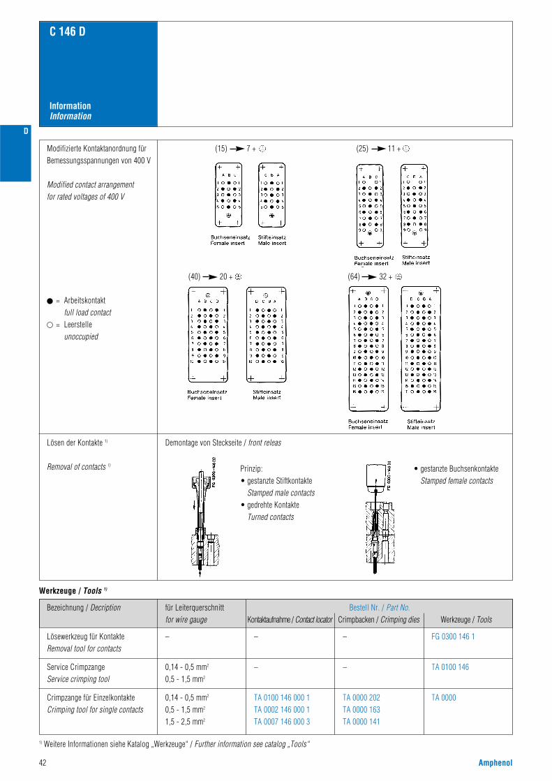
42 Amphenol
D
Modifizierte Kontaktanordnung fürBemessungsspannungen von 400 V
Modified contact arrangementfor rated voltages of 400 V
Lösen der Kontakte 1)
Removal of contacts 1)
1) Weitere Informationen siehe Katalog „Werkzeuge“ / Further information see catalog „Tools“
Demontage von Steckseite / front releas
(15) 7 + (25) 11 +
= Arbeitskontaktfull load contact
= Leerstelleunoccupied
InformationInformation
C 146 D
(40) 20 + (64) 32 +
Prinzip:• gestanzte Stiftkontakte
Stamped male contacts• gedrehte Kontakte
Turned contacts
• gestanzte BuchsenkontakteStamped female contacts
Bezeichnung / Decription
Werkzeuge / Tools 1)
Lösewerkzeug für KontakteRemoval tool for contacts
– – – FG 0300 146 1
0,14 - 0,5 mm2
0,5 - 1,5 mm2
– – TA 0100 146
0,14 - 0,5 mm2
0,5 - 1,5 mm2
1,5 - 2,5 mm2
TA 0100 146 000 1TA 0002 146 000 1TA 0007 146 000 3
TA 0000 202TA 0000 163TA 0000 141
TA 0000
Service CrimpzangeService crimping tool
Crimpzange für EinzelkontakteCrimping tool for single contacts
für Leiterquerschnittfor wire gauge
Bestell Nr. / Part No.Kontaktaufnahme / Contact locator Crimpbacken / Crimping dies Werkzeuge / Tools
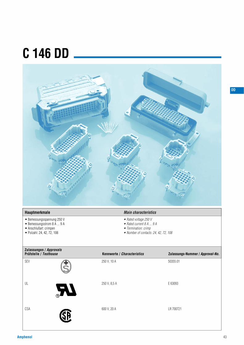
Amphenol 43
C 146 DD
• Bemessungsspannung 250 V• Bemessungsstrom 8 A ... 9 A• Anschlußart: crimpen• Polzahl: 24, 42, 72, 108
• Rated voltage 250 V• Rated current 8 A ... 9 A• Termination: crimp• Number of contacts: 24, 42, 72, 108
DD
Hauptmerkmale Main characteristics
SEV 250 V, 10 A 50355.01
UL 250 V, 8,5 A E 63093
CSA 600 V, 20 A LR 700721
Zulassungen / ApprovalsPrüfstelle / Testhouse Kennwerte / Characteristics Zulassungs-Nummer / Approval-No.
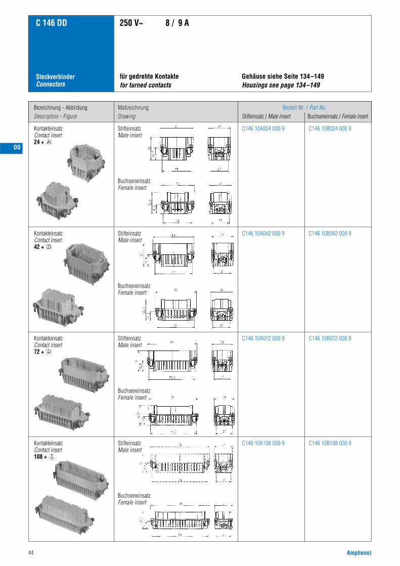
44 Amphenol
Bezeichnung - AbbildungDescription - Figure
MaßzeichnungDrawing
Bestell Nr. / Part No.Stifteinsatz / Male insert Buchseneinsatz / Female insert
C 146 DD
SteckverbinderConnectors
KontakteinsatzContact insert 24 +
Gehäuse siehe Seite 134–149Housings see page 134–149
für gedrehte Kontaktefor turned contacts
250 V~ 8 / 9 A
C146 10A024 000 9 C146 10B024 000 9
C146 10A042 000 9 C146 10B042 000 9
KontakteinsatzContact insert 72 +
C146 10A072 000 9 C146 10B072 000 9
C146 10A108 000 9 C146 10B108 000 9
KontakteinsatzContact insert42 +
StifteinsatzMale insert
BuchseneinsatzFemale insert
StifteinsatzMale insert
BuchseneinsatzFemale insert
StifteinsatzMale insert
BuchseneinsatzFemale insert
StifteinsatzMale insert
BuchseneinsatzFemale insert
KontakteinsatzContact insert108 +
DD
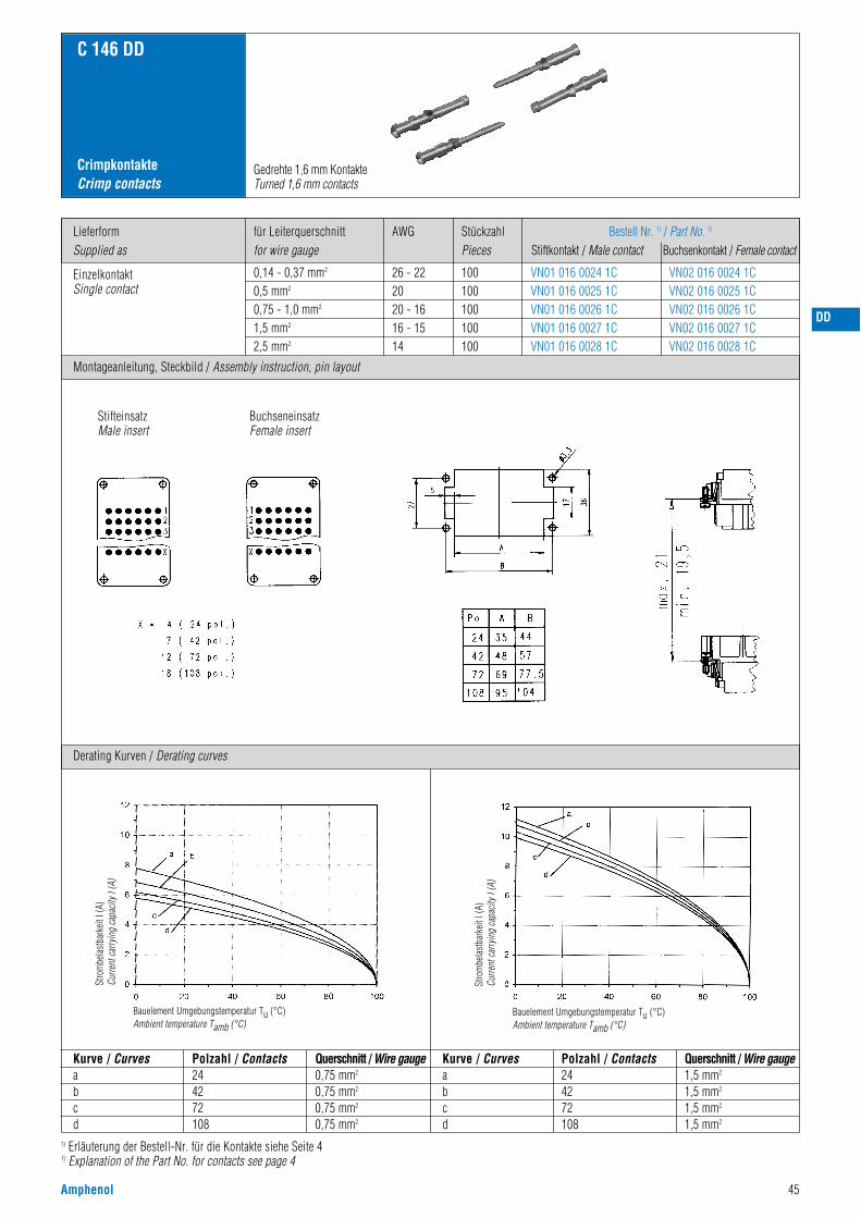
Amphenol 45
1) Erläuterung der Bestell-Nr. für die Kontakte siehe Seite 41) Explanation of the Part No. for contacts see page 4
LieferformSupplied as
AWGfür Leiterquerschnittfor wire gauge
StückzahlPieces
Bestell Nr. 1) / Part No. 1)
Stiftkontakt / Male contact Buchsenkontakt / Female contact
CrimpkontakteCrimp contacts
C 146 DD
0,14 - 0,37 mm2
0,5 mm2
0,75 - 1,0 mm2
1,5 mm2
2,5 mm2
26 - 222020 - 1616 - 1514
100100100100100
VN01 016 0024 1CVN01 016 0025 1CVN01 016 0026 1CVN01 016 0027 1CVN01 016 0028 1C
VN02 016 0024 1CVN02 016 0025 1CVN02 016 0026 1CVN02 016 0027 1CVN02 016 0028 1C
Derating Kurven / Derating curves
Montageanleitung, Steckbild / Assembly instruction, pin layout
EinzelkontaktSingle contact
Gedrehte 1,6 mm KontakteTurned 1,6 mm contacts
Kurve / Curvesabcd
Polzahl / Contacts244272108
Querschnitt / Wire gauge0,75 mm2
0,75 mm2
0,75 mm2
0,75 mm2
Kurve / Curvesabcd
Polzahl / Contacts244272108
Querschnitt / Wire gauge1,5 mm2
1,5 mm2
1,5 mm2
1,5 mm2
Stro
mbe
last
bark
eit I
(A)
Curre
nt c
arry
ing
capa
city
I (A
)
Bauelement Umgebungstemperatur Tu (°C)Ambient temperature Tamb (°C)
Stro
mbe
last
bark
eit I
(A)
Curre
nt c
arry
ing
capa
city
I (A
)
Bauelement Umgebungstemperatur Tu (°C)Ambient temperature Tamb (°C)
DD
StifteinsatzMale insert
BuchseneinsatzFemale insert
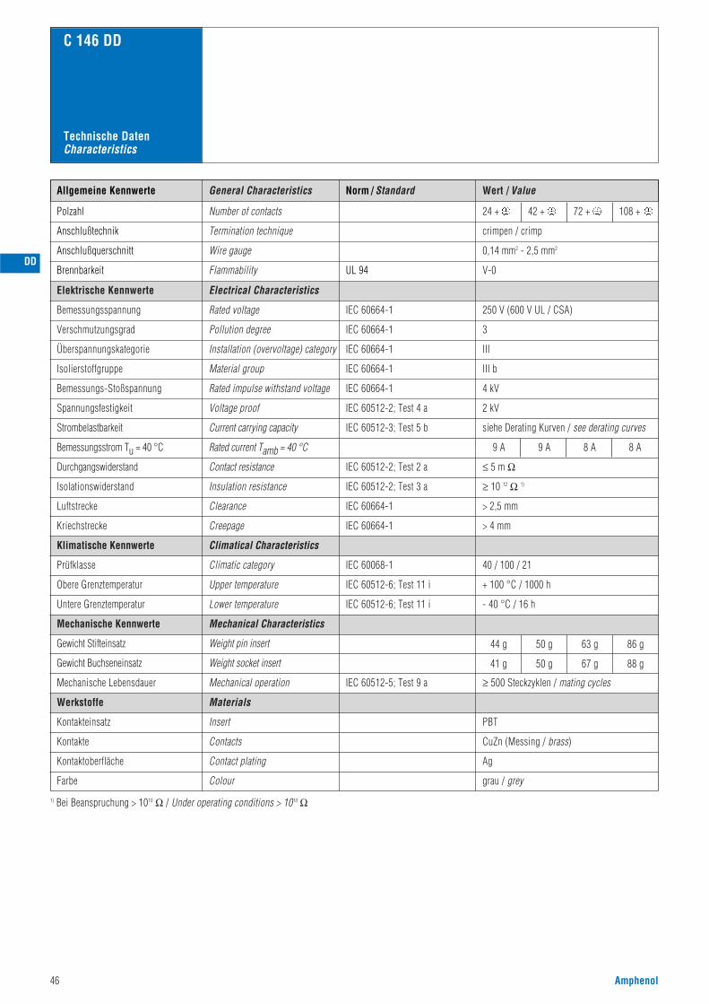
46 Amphenol
Norm / Standard Wert / Value
V-0
0,14 mm2 - 2,5 mm2
crimpen / crimp
24 + 42 + 72 + 108 +
C 146 DD
UL 94
Allgemeine Kennwerte
Polzahl
Anschlußquerschnitt
Anschlußtechnik
Brennbarkeit
Number of contacts
Wire gauge
Termination technique
Flammability
250 V (600 V UL / CSA)
3
III
III b
4 kV
2 kV
siehe Derating Kurven / see derating curves
≥ 10 12 Ω 1)
IEC 60664-1
IEC 60664-1
IEC 60664-1
IEC 60664-1
IEC 60664-1
IEC 60512-2; Test 4 a
IEC 60512-3; Test 5 b
IEC 60512-2; Test 3 a
IEC 60068-1
IEC 60512-5; Test 9 a
40 / 100 / 21
44 g
41 g
50 g
50 g
63 g
67 g
86 g
88 g
≥ 500 Steckzyklen / mating cycles
grau / grey
≤ 5 m Ω
9 A 9 A 8 A 8 A
IEC 60512-2; Test 2 a
IEC 60512-6; Test 11 i + 100 °C / 1000 h
IEC 60512-6; Test 11 i - 40 °C / 16 h
CuZn (Messing / brass)
PBT
Ag
Elektrische Kennwerte
Bemessungsspannung
Verschmutzungsgrad
Überspannungskategorie
Isolierstoffgruppe
Bemessungs-Stoßspannung
Spannungsfestigkeit
Strombelastbarkeit
Durchgangswiderstand
Isolationswiderstand
Klimatische Kennwerte
Prüfklasse
Obere Grenztemperatur
Untere Grenztemperatur
Mechanische Kennwerte
Gewicht Stifteinsatz
Gewicht Buchseneinsatz
Mechanische Lebensdauer
Werkstoffe
Kontakteinsatz
Kontakte
Kontaktoberfläche
Farbe
1) Bei Beanspruchung > 1010 Ω / Under operating conditions > 1010 Ω
Electrical Characteristics
Rated voltage
Pollution degree
Installation (overvoltage) category
Material group
Rated impulse withstand voltage
Voltage proof
Current carrying capacity
Bemessungsstrom Tu = 40 °C Rated current Tamb = 40 °C
Insulation resistance
> 2,5 mmIEC 60664-1Luftstrecke Clearance
> 4 mmIEC 60664-1Kriechstrecke Creepage
Climatical Characteristics
Climatic category
Mechanical Characteristics
Weight pin insert
Weight socket insert
Mechanical operation
Insert
Contact resistance
Upper temperature
Lower temperature
Contacts
Contact plating
Colour
Materials
General Characteristics
Technische DatenCharacteristics
DD
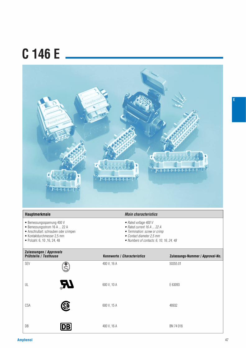
C 146 E
• Bemessungsspannung 400 V• Bemessungsstrom 16 A ... 22 A• Anschlußart: schrauben oder crimpen• Kontaktdurchmesser 2,5 mm• Polzahl: 6, 10 ,16, 24, 48
• Rated voltage 400 V• Rated current 16 A ... 22 A• Termination: screw or crimp• Contact diameter 2,5 mm• Numbers of contacts: 6, 10, 16, 24, 48
Amphenol 47
E
Hauptmerkmale Main characteristics
SEV 400 V, 16 A 50355.01
UL 600 V, 10 A E 63093
CSA 600 V, 15 A 48932
DB 400 V, 16 A BN 74 018
Zulassungen / ApprovalsPrüfstelle / Testhouse Kennwerte / Characteristics Zulassungs-Nummer / Approval-No.
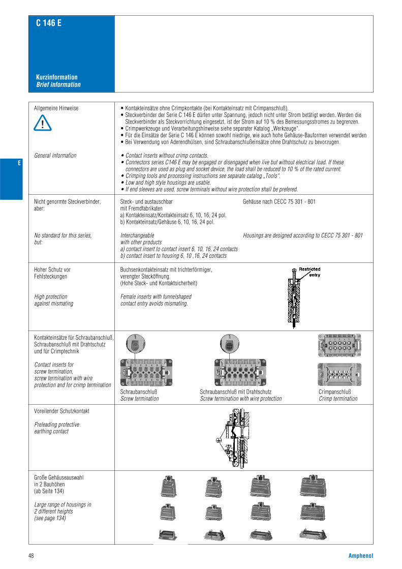
48 Amphenol
KurzinformationBrief information
C 146 E
Allgemeine Hinweise
General information
• Kontakteinsätze ohne Crimpkontakte (bei Kontakteinsatz mit Crimpanschluß).• Steckverbinder der Serie C 146 E dürfen unter Spannung, jedoch nicht unter Strom betätigt werden. Werden die
Steckverbinder als Steckvorrichtung eingesetzt, ist der Strom auf 10 % des Bemessungsstromes zu begrenzen.• Crimpwerkzeuge und Verarbeitungshinweise siehe separater Katalog „Werkzeuge“.• Für die Einsätze der Serie C 146 E können sowohl niedrige, wie auch hohe Gehäuse-Bauformen verwendet werden• Bei Verwendung von Aderendhülsen, sind Schraubanschlußeinsätze ohne Drahtschutz zu bevorzugen.
• Contact inserts without crimp contacts.• Connectors series C146 E may be engaged or disengaged when live but without electrical load. If these
connectors are used as plug and socket device, the load shall be reduced to 10 % of the rated current.• Crimping tools and processing instructions see separate catalog „Tools“.• Low and high style housings are usable.• If end sleeves are used, screw terminals without wire protection shall be prefered.
Voreilender Schutzkontakt
Preleading protectiveearthing contact
Große Gehäuseauswahlin 2 Bauhöhen(ab Seite 134)
Large range of housings in2 different heights (see page 134)
Nicht genormte Steckverbinder,aber:
No standard for this series,but:
Steck- und austauschbarmit Fremdfabrikatena) Kontakteinsatz/Kontakteinsatz 6, 10, 16, 24 pol. b) Kontakteinsatz/Gehäuse 6, 10, 16, 24 pol.
Interchangeablewith other productsa) contact insert to contact insert 6, 10, 16, 24 contactsb) contact insert to housing 6, 10 ,16, 24 contacts
Gehäuse nach CECC 75 301 - 801
Housings are designed according to CECC 75 301 - 801
E
Hoher Schutz vorFehlsteckungen
High protectionagainst mismating
Buchsenkontakteinsatz mit trichterförmiger,verengter Stecköffnung.(Hohe Steck- und Kontaktsicherheit)
Female inserts with funnelshaped contact entry avoids mismating.
Kontakteinsätze für Schraubanschluß,Schraubanschluß mit Drahtschutzund für Crimptechnik
Contact inserts for screw termination, screw termination with wireprotection and for crimp termination
SchraubanschlußScrew termination
Schraubanschluß mit DrahtschutzScrew termination with wire protection
CrimpanschlußCrimp termination
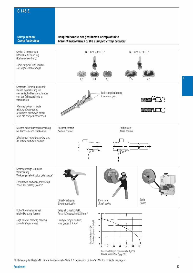
Amphenol 49
Crimp TechnikCrimp technology
C 146 E
1) Erläuterung der Bestell-Nr. für die Kontakte siehe Seite 4 / Explanation of the Part No. for contacts see page 4
Großer CrimpbereichGasdichte Verbindung(Kaltverschweißung)
Large range of wire gaugesGas-tight (coldwelding)
Gestanzte Crimpkontakte mitIsolierungshalterung ummechanische Beanspruchungenvon der Crimpverbindungfernzuhalten
Stamped crimp contacts with insulation crimpto absorbe mechnical stress from the crimped connection
Mechanischer Rasthakenanschlagbei Buchsen- und Stiftkontakt
Mechanical retention spring stop on female and male contact
Kostengünstige, einfacheVerarbeitung.Werkzeuge siehe Katalog „Werkzeuge“
Economical and easy processingTools see catalog „Tools“
Hohe Strombelastbarkeit(siehe Derating Kurven)
High current carrying capacity(see derating curves)
Beispiel Einzelkontakt, Anschlußquerschnitt 2,5 mm2
Example single contact,wire gauge 2.5 mm2
Einzel-FertigungSingle production
Hauptmerkmale der gestanzten CrimpkontakteMain characteristics of the stamped crimp contacts
IsolierungshalterungInsulation grip
KleinserieSmall series
SerieSeries
BuchsenkontaktFemale contact
StiftkontaktMale contact
0,5
.N01 025 0001 (1) 1) .N01 025 0010 (1) 1)
1,0 1,5 1,5 2,5 E
Stro
mbe
last
bark
eit I
(A)
Curre
nt ca
rryin
g ca
pacit
y I (A
)
Bauelement Umgebungstemperatur Tu (°C)Ambient temperature Tamb (°C)
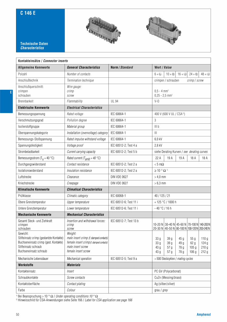
50 Amphenol
Norm / Standard Wert / ValueAllgemeine Kennwerte
Kontakteinsätze / Connector inserts
Polzahl
400 V (600 V UL / CSA 2))
3
III b
III
Number of contacts
Anschlußtechnik Termination technique crimpen / schrauben crimp / screw
Anschlußquerschnitt:crimpenschrauben
Wire gauge:crimpscrew
0,5 - 4 mm2
0,25 - 2,5 mm2
Brennbarkeit Flammability V-OUL 94
6 + 10 + 16 + 24 + 48 +
Electrical Characteristics
Rated voltage
Pollution degree
C 146 E
IEC 60664-1
IEC 60664-1
IEC 60664-1
IEC 60664-1
Elektrische Kennwerte
Bemessungsspannung
Verschmutzungsgrad
General Characteristics
Technische DatenCharacteristics
6,0 kV
2,8 kV
siehe Derating Kurven / see derating curves
Material group
Installation (overvoltage) category
Rated impulse withstand voltage
Voltage proof
IEC 60664-1
IEC 60512-2; Test 4 a
IEC 60512-2; Test 5 bCurrent carrying capacity
Isolierstoffgruppe
Überspannungskategorie
Bemessungs-Stoßspannung
Spannungsfestigkeit
Strombelastbarkeit
Rated current (Tamb = 40 °C)Bemessungsstrom (Tu = 40 °C)
Mechanische Lebensdauer
Climatical Characteristics
Mechanical Characteristics
< 5 mΩ
22 A 19 A 19 A 18 A 18 A
IEC 60512-2; Test 2 a
IEC 60068-1
IEC 60512-7; Test 13 b
IEC 60512-5; Test 9 a
Contact resistance
Climatic category
Insertion and withdrawal forces:crimpscrewWeight:male insert crimp (f. stamped contacts)female insert crimp(f. stamped contacts)male insert screwfemale insert screw
Insert
40 / 125 / 21
33 g33 g43 g43 g
39 g39 g57 g57 g
45 g49 g78 g78 g
55 g62 g
105 g106 g
110 g124 g210 g212 g
PC GV (Polycarbonat)
grau / grey
Durchgangswiderstand
≥ 10 12 Ω 1)IEC 60512-2; Test 2 aInsulation resistanceIsolationswiderstand
> 4,0 mmClearanceLuftstrecke
> 6,3 mmDIN VDE 0627
DIN VDE 0627
CreepageKriechstrecke
Klimatische Kennwerte
Prüfklasse
Mechanische Kennwerte
Gesamt Steck- und ZiehkraftcrimpenschraubenGewicht:Stifteinsatz crimp (gestantzte Kontakte)Buchseneinsatz crimp (gest. Kontakte)Stifteinsatz schraubBuchseneinsatz schraub
Mechanical operation > 500 Steckzyklen / mating cycles
Werkstoffe
Kontakteinsatz
Screw contacts CuZn (Messing/brass)Schraubkontakte
Kontaktoberfläche Contact plating Ag (silber/silver)
Farbe Colour
Materials
IEC 60512-6; Test 11 iUpper temperature
Lower temperature
+ 125 °C / 1000 hObere Grenztemperatur
Untere Grenztemperatur IEC 60512-6; Test 11 i - 40 °C / 16 h
20-30 N 40-50 N 80-100 N 100-120 N 200-240 N10-20 N 30-40 N 45-60 N 70-100 N 140-200 N
E
1) Bei Beanspruchung > 10 10 Ω / Under operating conditions 10 10 Ω2) Hinweisschild für CSA-Anwendungen siehe Seite 166 / Label for CSA application see page 166
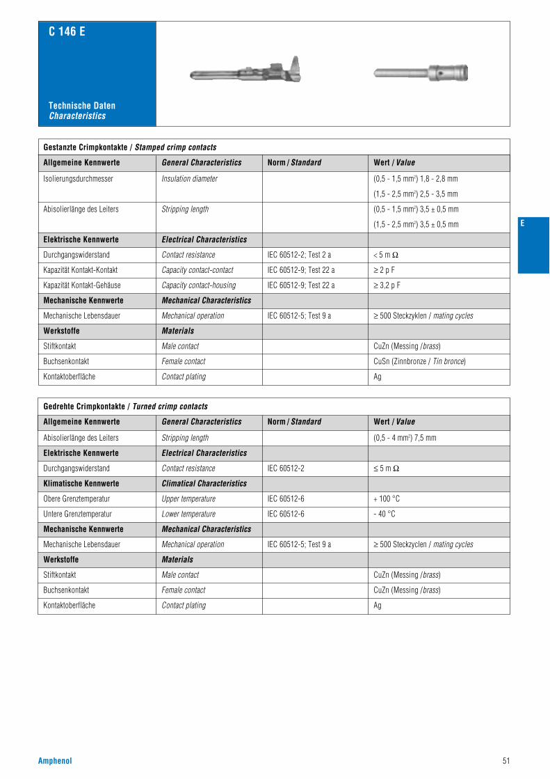
Amphenol 51
C 146 E
Norm / Standard Wert / ValueAllgemeine Kennwerte
Gestanzte Crimpkontakte / Stamped crimp contacts
Isolierungsdurchmesser
Abisolierlänge des Leiters
IEC 60512-2; Test 2 a
IEC 60512-9; Test 22 a
IEC 60512-9; Test 22 a
< 5 m Ω
(0,5 - 1,5 mm2) 1,8 - 2,8 mm
(1,5 - 2,5 mm2) 2,5 - 3,5 mm
(0,5 - 1,5 mm2) 3,5 ± 0,5 mm
(1,5 - 2,5 mm2) 3,5 ± 0,5 mm
≥ 2 p F
≥ 3,2 p F
Elektrische Kennwerte
Durchgangswiderstand
Kapazität Kontakt-Kontakt
Kapazität Kontakt-Gehäuse
IEC 60512-5; Test 9 a ≥ 500 Steckzyklen / mating cycles
Mechanische Kennwerte
Mechanische Lebensdauer
Werkstoffe
CuZn (Messing /brass)Stiftkontakt
Buchsenkontakt
Kontaktoberfläche
Insulation diameter
Stripping length
Electrical Characteristics
Contact resistance
Capacity contact-contact
Capacity contact-housing
Mechanical Characteristics
Mechanical operation
Male contact
Female contact
Contact plating
Materials
General Characteristics
CuSn (Zinnbronze / Tin bronce)
Ag
Technische DatenCharacteristics
Elektrische Kennwerte Electrical Characteristics
IEC 60512-2
Abisolierlänge des Leiters Stripping length
Gedrehte Crimpkontakte / Turned crimp contacts
Klimatische Kennwerte Climatical Characteristics
IEC 60512-6
IEC 60512-6
+ 100 °CObere Grenztemperatur Upper temperature
- 40 °CUntere Grenztemperatur Lower temperature
Norm / Standard Wert / ValueAllgemeine Kennwerte General Characteristics
(0,5 - 4 mm2) 7,5 mm
≤ 5 m Ω
Mechanische Kennwerte
Werkstoffe
Mechanical Characteristics
Materials
IEC 60512-5; Test 9 a
Durchgangswiderstand
Mechanische Lebensdauer
Contact resistance
Mechanical operation ≥ 500 Steckzyclen / mating cycles
Stiftkontakt
Buchsenkontakt
Kontaktoberfläche
Male contact
Female contact
Contact plating
CuZn (Messing /brass)
CuZn (Messing /brass)
Ag
E
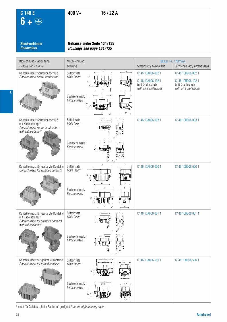
52 Amphenol
Bezeichnung - AbbildungDescription - Figure
MaßzeichnungDrawing
Bestell Nr. / Part No.Stifteinsatz / Male insert Buchseneinsatz / Female insert
C 146 E
6 +
SteckverbinderConnectors
Kontakteinsatz SchraubanschlußContact insert screw termination
Gehäuse siehe Seite 134/135Housings see page 134/135
400 V~ 16 / 22 A
C146 10A006 002 1
C146 10A006 102 1(mit Drahtschutz with wire protection)
C146 10B006 002 1
C146 10B006 102 1(mit Drahtschutz with wire protection)
C146 10A006 003 1 C146 10B006 003 1
Kontakteinsatz für gestanzte KontakteContact insert for stamped contacts
C146 10A006 000 1 C146 10B006 000 1
1) nicht für Gehäuse „hohe Bauform“ geeignet / not for high housing style
C146 10A006 001 1 C146 10B006 001 1
Kontakteinsatz für gedrehte KontakteContact insert for turned contacts
C146 10A006 500 1 C146 10B006 500 1
StifteinsatzMale insert
BuchseneinsatzFemale insert
StifteinsatzMale insert
BuchseneinsatzFemale insert
StifteinsatzMale insert
BuchseneinsatzFemale insert
StifteinsatzMale insert
BuchseneinsatzFemale insert
StifteinsatzMale insert
BuchseneinsatzFemale insert
E
Kontakteinsatz Schraubanschlußmit Kabelabfang 1)
Contact insert screw terminationwith cable clamp 1)
Kontakteinsatz für gestanzte Kontaktemit Kabelabfang 1)
Contact insert for stamped contactswith cable clamp 1)
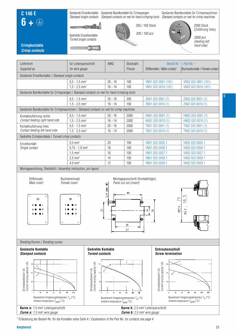
Amphenol 53
E
1) Erläuterung der Bestell-Nr. für die Kontakte siehe Seite 4 / Explanation of the Part No. for contacts see page 4
Gestanzte Einzelkontakte / Stamped single contacts
Gestanzte Bandkontakte für Crimpzangen / Stamped contacts on reel for hand crimping tools
Gestanzte Bandkontakte für Crimpmaschinen / Stamped contacts on reel for crimp machines
LieferformSupplied as
AWGfür Leiterquerschnittfor wire gauge
StückzahlPieces
Bestell Nr. 1) / Part No. 1)
Stiftkontakt / Male contact Buchsenkontakt / Female contact
CrimpkontakteCrimp contacts
C 146 E
6 +
0,5 - 1,5 mm2
1,5 - 2,5 mm2
0,5 - 1,5 mm2
1,5 - 2,5 mm2
0,5 mm2
0,75 - 1,0 mm2
1,5 mm2
2,5 mm2
4,0 mm2
0,5 - 1,5 mm2
1,5 - 2,5 mm2
0,5 - 1,5 mm2
1,5 - 2,5 mm2
20 - 1616 - 1420 - 1616 - 14
2018161412
20 - 1616 - 14
20 - 1616 - 14
2000200020002000
100100100100100
200100
100100
HN01 025 0001 (1)HN01 025 0010 (1)TN01 025 0001 (1)TN01 025 0010 (1)
VN01 025 0035 1VN01 025 0036 1VN01 025 0037 1VN01 025 0038 1VN01 025 0039 1
ZN01 025 0001 (1)ZN01 025 0010 (1)
VN01 025 0001 (101)VN01 025 0010 (101)
HN02 025 0001 (1)HN02 025 0010 (1)TN02 025 0001 (1)TN02 025 0010 (1)
VN02 025 0035 1VN02 025 0036 1VN02 025 0037 1VN02 025 0038 1VN02 025 0039 1
ZN02 025 0001 (1)ZN02 025 0010 (1)
VN02 025 0001 (101)VN02 025 0010 (101)
Kontaktzuführung rechtsContact feeding right hand side
Kontaktzuführung linksContact feeding left hand side
EinzelkontaktSingle contact
Gedrehte Crimpkontakte / Turned crimp contacts
Montageanleitung, Steckbild / Assembly instruction, pin layout
Derating Kurven / Derating curves
Gestanzte Bandkontakte für CrimpmaschinenStamped contacts on reel for crimp machines
200 / 100 Stück
200 / 100 pcs
2000 Stück(Zuführung links)
2000 pcs(feeding lefthand side)
Gestanzte EinzelkontakteStamped single contacts
Gestanzte Bandkontakte für CrimpzangenStamped contacts on reel for hand crimping tools
Gedrehte EinzelkontakteTurned single contacts
Kurve a: 1,5 mm2 LeiterquerschnittCurve a: 1,5 mm2 wire gauge
Kurve b: 2,5 mm2 LeiterquerschnittCurve b: 2,5 mm2 wire gauge
Stro
mbe
last
bark
eit I
(A)
Curre
nt c
arry
ing
capa
city
I (A
)
Bauelement Umgebungstemperatur Tu (°C)Ambient temperature Tamb (°C)
Stro
mbe
last
bark
eit I
(A)
Curre
nt c
arry
ing
capa
city
I (A
)
Bauelement Umgebungstemperatur Tu (°C)Ambient temperature Tamb (°C)
Stro
mbe
last
bark
eit I
(A)
Curre
nt c
arry
ing
capa
city
I (A
)
Bauelement Umgebungstemperatur Tu (°C)Ambient temperature Tamb (°C)
Gestanzte KontakteStamped contacts
SchraubanschlußScrew termination
StifteinsatzMale insert
BuchseneinsatzFemale insert
Montageausschnitt (Kontaktträger)Panel cut out (insert)
Gedrehte KontakteTurned contacts

54 Amphenol
E
Bezeichnung - AbbildungDescription - Figure
MaßzeichnungDrawing
Bestell Nr. / Part No.Stifteinsatz / Male insert Buchseneinsatz / Female insert
C 146 E
10 +
SteckverbinderConnectors
Kontakteinsatz SchraubanschlußContact insert screw termination
Gehäuse siehe Seite 136–139 Housings see page 136–139
400 V~ 16 / 22 A
C146 10A010 002 1
C146 10A010 102 1(mit Drahtschutz with wire protection)
C146 10B010 002 1
C146 10B010 102 1(mit Drahtschutz with wire protection)
C146 10A010 003 1 C146 10B010 003 1
Kontakteinsatz für gestanzte KontakteContact insert for stamped contacts
C146 10A010 000 1 C146 10B010 000 1
1) nicht für Gehäuse „hohe Bauform“ geeignet / not for high housing style
C146 10A010 001 1 C146 10B010 001 1
C146 10A010 500 1 C146 10B010 500 1Kontakteinsatz für gedrehte KontakteContact insert for turned contacts
StifteinsatzMale insert
BuchseneinsatzFemale insert
StifteinsatzMale insert
BuchseneinsatzFemale insert
StifteinsatzMale insert
BuchseneinsatzFemale insert
StifteinsatzMale insert
BuchseneinsatzFemale insert
StifteinsatzMale insert
BuchseneinsatzFemale insert
Kontakteinsatz Schraubanschlußmit Kabelabfang 1)
Contact insert screw terminationwith cable clamp 1)
Kontakteinsatz für gestanzte Kontaktemit Kabelabfang 1)
Contact insert for stamped contactswith cable clamp 1)
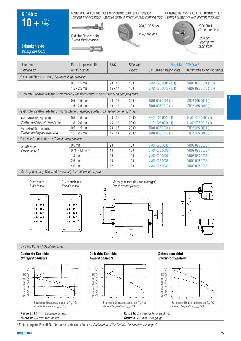
Amphenol 55
E
Gestanzte Einzelkontakte / Stamped single contacts
Gestanzte Bandkontakte für Crimpzangen / Stamped contacts on reel for hand crimping tools
Gestanzte Bandkontakte für Crimpmaschinen/ Stamped contacts on reel for crimp machines
LieferformSupplied as
AWGfür Leiterquerschnittfor wire gauge
StückzahlPieces
Bestell Nr. 1) / Part No. 1)
Stiftkontakt / Male contact Buchsenkontakt / Female contact
CrimpkontakteCrimp contacts
C 146 E
10 +
0,5 - 1,5 mm2
1,5 - 2,5 mm2
0,5 - 1,5 mm2
1,5 - 2,5 mm2
0,5 mm2
0,75 - 1,0 mm2
1,5 mm2
2,5 mm2
4,0 mm2
0,5 - 1,5 mm2
1,5 - 2,5 mm2
0,5 - 1,5 mm2
1,5 - 2,5 mm2
20 - 1616 - 1420 - 1616 - 14
2018161412
20 - 1616 - 14
20 - 1616 - 14
2000200020002000
100100100100100
200100
100100
HN01 025 0001 (1)HN01 025 0010 (1)TN01 025 0001 (1)TN01 025 0010 (1)
ZN01 025 0001 (1)ZN01 025 0010 (1)
VN01 025 0001 (101)VN01 025 0010 (101)
HN02 025 0001 (1)HN02 025 0010 (1)TN02 025 0001 (1)TN02 025 0010 (1)
ZN02 025 0001 (1)ZN02 025 0010 (1)
VN02 025 0001 (101)VN02 025 0010 (101)
Kontaktzuführung rechtsContact feeding right hand side
Kontaktzuführung linksContact feeding left hand side
EinzelkontaktSingle contact
Gedrehte Crimpkontakte / Turned crimp contacts
Montageanleitung, Steckbild / Assembly instruction, pin layout
Derating Kurven / Derating curves
Gestanzte Bandkontakte für CrimpmaschinenStamped contacts on reel for crimp machines
200 / 100 Stück
200 / 100 pcs
2000 Stück(Zuführung links)
2000 pcs(feeding lefthand side)
Gestanzte EinzelkontakteStamped single contacts
Gestanzte Bandkontakte für CrimpzangenStamped contacts on reel for hand crimping tools
Gedrehte EinzelkontakteTurned single contacts
Kurve a: 1,5 mm2 LeiterquerschnittCurve a: 1,5 mm2 wire gauge
Kurve b: 2,5 mm2 LeiterquerschnittCurve b: 2,5 mm2 wire gauge
Gestanzte KontakteStamped contacts
SchraubanschlußScrew termination
Montageausschnitt (Kontaktträger)Panel cut out (insert)
StifteinsatzMale insert
BuchseneinsatzFemale insert
Gedrehte KontakteTurned contacts
1) Erläuterung der Bestell-Nr. für die Kontakte siehe Seite 4 / Explanation of the Part No. for contacts see page 4
VN01 025 0035 1VN01 025 0036 1VN01 025 0037 1VN01 025 0038 1VN01 025 0039 1
VN02 025 0035 1VN02 025 0036 1VN02 025 0037 1VN02 025 0038 1VN02 025 0039 1
Stro
mbe
last
bark
eit I
(A)
Curre
nt c
arry
ing
capa
city
I (A
)
Bauelement Umgebungstemperatur Tu (°C)Ambient temperature Tamb (°C)
Stro
mbe
last
bark
eit I
(A)
Curre
nt c
arry
ing
capa
city
I (A
)
Bauelement Umgebungstemperatur Tu (°C)Ambient temperature Tamb (°C)
Stro
mbe
last
bark
eit I
(A)
Curre
nt c
arry
ing
capa
city
I (A
)
Bauelement Umgebungstemperatur Tu (°C)Ambient temperature Tamb (°C)
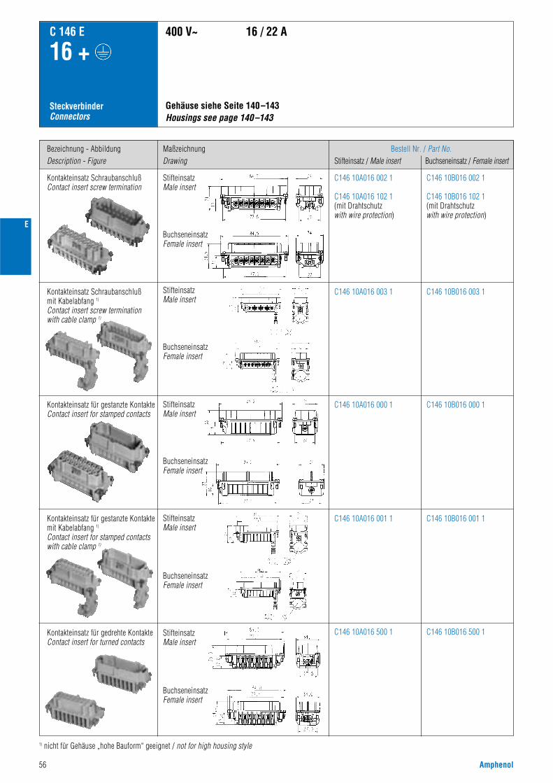
56 Amphenol
E
Bezeichnung - AbbildungDescription - Figure
MaßzeichnungDrawing
Bestell Nr. / Part No.Stifteinsatz / Male insert Buchseneinsatz / Female insert
C 146 E
16 +
SteckverbinderConnectors
Kontakteinsatz SchraubanschlußContact insert screw termination
Gehäuse siehe Seite 140–143 Housings see page 140–143
400 V~ 16 / 22 A
C146 10A016 002 1
C146 10A016 102 1(mit Drahtschutz with wire protection)
C146 10B016 002 1
C146 10B016 102 1(mit Drahtschutz with wire protection)
C146 10A016 003 1 C146 10B016 003 1
Kontakteinsatz für gestanzte KontakteContact insert for stamped contacts
C146 10A016 000 1 C146 10B016 000 1
Kontakteinsatz für gestanzte Kontaktemit Kabelabfang 1)
Contact insert for stamped contactswith cable clamp 1)
1) nicht für Gehäuse „hohe Bauform“ geeignet / not for high housing style
C146 10A016 001 1 C146 10B016 001 1
C146 10A016 500 1 C146 10B016 500 1Kontakteinsatz für gedrehte KontakteContact insert for turned contacts
StifteinsatzMale insert
BuchseneinsatzFemale insert
StifteinsatzMale insert
BuchseneinsatzFemale insert
StifteinsatzMale insert
BuchseneinsatzFemale insert
StifteinsatzMale insert
BuchseneinsatzFemale insert
StifteinsatzMale insert
BuchseneinsatzFemale insert
Kontakteinsatz Schraubanschlußmit Kabelabfang 1)
Contact insert screw terminationwith cable clamp 1)

Amphenol 57
E
Gestanzte Einzelkontakte / Stamped single contacts
Gestanzte Bandkontakte für Crimpzangen / Stamped contacts on reel for hand crimping tools
Gestanzte Bandkontakte für Crimpmaschinen/ Stamped contacts on reel for crimp machines
LieferformSupplied as
AWGfür Leiterquerschnittfor wire gauge
StückzahlPieces
Bestell Nr. 1) / Part No. 1)
Stiftkontakt / Male contact Buchsenkontakt / Female contact
CrimpkontakteCrimp contacts
C 146 E
16 +
0,5 - 1,5 mm2
1,5 - 2,5 mm2
0,5 - 1,5 mm2
1,5 - 2,5 mm2
0,5 mm2
0,75 - 1,0 mm2
1,5 mm2
2,5 mm2
4,0 mm2
0,5 - 1,5 mm2
1,5 - 2,5 mm2
0,5 - 1,5 mm2
1,5 - 2,5 mm2
20 - 1616 - 1420 - 1616 - 14
2018161412
20 - 1616 - 14
20 - 1616 - 14
2000200020002000
100100100100100
200100
100100
HN01 025 0001 (1)HN01 025 0010 (1)TN01 025 0001 (1)TN01 025 0010 (1)
ZN01 025 0001 (1)ZN01 025 0010 (1)
VN01 025 0001 (101)VN01 025 0010 (101)
HN02 025 0001 (1)HN02 025 0010 (1)TN02 025 0001 (1)TN02 025 0010 (1)
ZN02 025 0001 (1)ZN02 025 0010 (1)
VN02 025 0001 (101)VN02 025 0010 (101)
Kontaktzuführung rechtsContact feeding right hand side
Kontaktzuführung linksContact feeding left hand side
EinzelkontaktSingle contact
Gedrehte Crimpkontakte / Turned crimp contacts
Montageanleitung, Steckbild / Assembly instruction, pin layout
Derating Kurven / Derating curves
Gestanzte Bandkontakte für CrimpmaschinenStamped contacts on reel for crimp machines
200 / 100 Stück
200 / 100 pcs
2000 Stück(Zuführung links)
2000 pcs(feeding lefthand side)
Gestanzte EinzelkontakteStamped single contacts
Gestanzte Bandkontakte für CrimpzangenStamped contacts on reel for hand crimping tools
Gedrehte EinzelkontakteTurned single contacts
Kurve a: 1,5 mm2 LeiterquerschnittCurve a: 1,5 mm2 wire gauge
Kurve b: 2,5 mm2 LeiterquerschnittCurve b: 2,5 mm2 wire gauge
Gestanzte KontakteStamped contacts
SchraubanschlußScrew termination
Montageausschnitt (Kontaktträger)Panel cut out (insert)
StifteinsatzMale insert
BuchseneinsatzFemale insert
Gedrehte KontakteTurned contacts
1) Erläuterung der Bestell-Nr. für die Kontakte siehe Seite 4 / Explanation of the Part No. for contacts see page 4
VN01 025 0035 1VN01 025 0036 1VN01 025 0037 1VN01 025 0038 1VN01 025 0039 1
VN02 025 0035 1VN02 025 0036 1VN02 025 0037 1VN02 025 0038 1VN02 025 0039 1
Stro
mbe
last
bark
eit I
(A)
Curre
nt c
arry
ing
capa
city
I (A
)
Bauelement Umgebungstemperatur Tu (°C)Ambient temperature Tamb (°C)
Stro
mbe
last
bark
eit I
(A)
Curre
nt c
arry
ing
capa
city
I (A
)
Bauelement Umgebungstemperatur Tu (°C)Ambient temperature Tamb (°C)
Stro
mbe
last
bark
eit I
(A)
Curre
nt c
arry
ing
capa
city
I (A
)
Bauelement Umgebungstemperatur Tu (°C)Ambient temperature Tamb (°C)

58 Amphenol
E
Bezeichnung - AbbildungDescription - Figure
MaßzeichnungDrawing
Bestell Nr. / Part No.Stifteinsatz / Male insert Buchseneinsatz / Female insert
C 146 E
24 +
SteckverbinderConnectors
Kontakteinsatz SchraubanschlußContact insert screw termination
Gehäuse siehe Seite 144–147Housings see page 144–147
400 V~ 16 / 22 A
C146 10A024 002 1
C146 10A024 102 1(mit Drahtschutz with wire protection)
C146 10B024 002 1
C146 10B024 102 1(mit Drahtschutz with wire protection)
C146 10A024 003 1 C146 10B024 003 1
Kontakteinsatz für gestanzte KontakteContact insert for stamped contacts
C146 10A024 000 1 C146 10B024 000 1
1) nicht für Gehäuse „hohe Bauform“ geeignet / not for high housing style
C146 10A024 001 1 C146 10B024 001 1
C146 10A024 500 1 C146 10B024 500 1Kontakteinsatz für gedrehte KontakteContact insert for turned contacts
BuchseneinsatzFemale insert
StifteinsatzMale insert
BuchseneinsatzFemale insert
StifteinsatzMale insert
BuchseneinsatzFemale insert
StifteinsatzMale insert
BuchseneinsatzFemale insert
StifteinsatzMale insert
BuchseneinsatzFemale insert
StifteinsatzMale insert
Kontakteinsatz Schraubanschlußmit Kabelabfang 1)
Contact insert screw terminationwith cable clamp 1)
Kontakteinsatz für gestanzte Kontaktemit Kabelabfang 1)
Contact insert for stamped contactswith cable clamp 1)

Amphenol 59
E
Gestanzte Einzelkontakte / Stamped single contacts
Gestanzte Bandkontakte für Crimpzangen / Stamped contacts on reel for hand crimping tools
Gestanzte Bandkontakte für Crimpmaschinen/ Stamped contacts on reel for crimp machines
LieferformSupplied as
AWGfür Leiterquerschnittfor wire gauge
StückzahlPieces
Bestell Nr. 1) / Part No. 1)
Stiftkontakt / Male contact Buchsenkontakt / Female contact
CrimpkontakteCrimp contacts
C 146 E
24 +
0,5 - 1,5 mm2
1,5 - 2,5 mm2
0,5 - 1,5 mm2
1,5 - 2,5 mm2
0,5 mm2
0,75 - 1,0 mm2
1,5 mm2
2,5 mm2
4,0 mm2
0,5 - 1,5 mm2
1,5 - 2,5 mm2
0,5 - 1,5 mm2
1,5 - 2,5 mm2
20 - 1616 - 1420 - 1616 - 14
2018161412
20 - 1616 - 14
20 - 1616 - 14
2000200020002000
100100100100100
200100
100100
HN01 025 0001 (1)HN01 025 0010 (1)TN01 025 0001 (1)TN01 025 0010 (1)
ZN01 025 0001 (1)ZN01 025 0010 (1)
VN01 025 0001 (101)VN01 025 0010 (101)
HN02 025 0001 (1)HN02 025 0010 (1)TN02 025 0001 (1)TN02 025 0010 (1)
ZN02 025 0001 (1)ZN02 025 0010 (1)
VN02 025 0001 (101)VN02 025 0010 (101)
Kontaktzuführung rechtsContact feeding right hand side
Kontaktzuführung linksContact feeding left hand side
EinzelkontaktSingle contact
Gedrehte Crimpkontakte / Turned crimp contacts
Montageanleitung, Steckbild / Assembly instruction, pin layout
Derating Kurven / Derating curves
Gestanzte Bandkontakte für CrimpmaschinenStamped contacts on reel for crimp machines
200 / 100 Stück
200 / 100 pcs
2000 Stück(Zuführung links)
2000 pcs(feeding lefthand side)
Gestanzte EinzelkontakteStamped single contacts
Gestanzte Bandkontakte für CrimpzangenStamped contacts on reel for hand crimping tools
Gedrehte EinzelkontakteTurned single contacts
Kurve a: 1,5 mm2 LeiterquerschnittCurve a: 1,5 mm2 wire gauge
Kurve b: 2,5 mm2 LeiterquerschnittCurve b: 2,5 mm2 wire gauge
Gestanzte KontakteStamped contacts
SchraubanschlußScrew termination
Montageausschnitt (Kontaktträger)Panel cut out (insert)
StifteinsatzMale insert
BuchseneinsatzFemale insert
Gedrehte KontakteTurned contacts
1) Erläuterung der Bestell-Nr. für die Kontakte siehe Seite 4 / Explanation of the Part No. for contacts see page 4
VN01 025 0035 1VN01 025 0036 1VN01 025 0037 1VN01 025 0038 1VN01 025 0039 1
VN02 025 0035 1VN02 025 0036 1VN02 025 0037 1VN02 025 0038 1VN02 025 0039 1
Stro
mbe
last
bark
eit I
(A)
Curre
nt c
arry
ing
capa
city
I (A
)
Bauelement Umgebungstemperatur Tu (°C)Ambient temperature Tamb (°C)
Stro
mbe
last
bark
eit I
(A)
Curre
nt c
arry
ing
capa
city
I (A
)
Bauelement Umgebungstemperatur Tu (°C)Ambient temperature Tamb (°C)
Stro
mbe
last
bark
eit I
(A)
Curre
nt c
arry
ing
capa
city
I (A
)
Bauelement Umgebungstemperatur Tu (°C)Ambient temperature Tamb (°C)
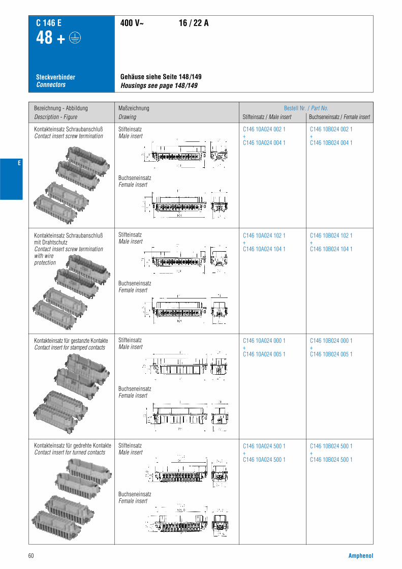
60 Amphenol
E
Bezeichnung - AbbildungDescription - Figure
MaßzeichnungDrawing
Bestell Nr. / Part No.Stifteinsatz / Male insert Buchseneinsatz / Female insert
C 146 E
48 +
SteckverbinderConnectors
Kontakteinsatz SchraubanschlußContact insert screw termination
Gehäuse siehe Seite 148/149Housings see page 148/149
400 V~ 16 / 22 A
C146 10A024 002 1+C146 10A024 004 1
C146 10B024 002 1+C146 10B024 004 1
Kontakteinsatz Schraubanschlußmit DrahtschutzContact insert screw terminationwith wireprotection
C146 10A024 102 1+C146 10A024 104 1
C146 10B024 102 1+C146 10B024 104 1
Kontakteinsatz für gestanzte KontakteContact insert for stamped contacts
C146 10A024 000 1+C146 10A024 005 1
C146 10B024 000 1+C146 10B024 005 1
C146 10A024 500 1+C146 10A024 500 1
C146 10B024 500 1+C146 10B024 500 1
Kontakteinsatz für gedrehte KontakteContact insert for turned contacts
BuchseneinsatzFemale insert
StifteinsatzMale insert
BuchseneinsatzFemale insert
StifteinsatzMale insert
BuchseneinsatzFemale insert
StifteinsatzMale insert
BuchseneinsatzFemale insert
StifteinsatzMale insert
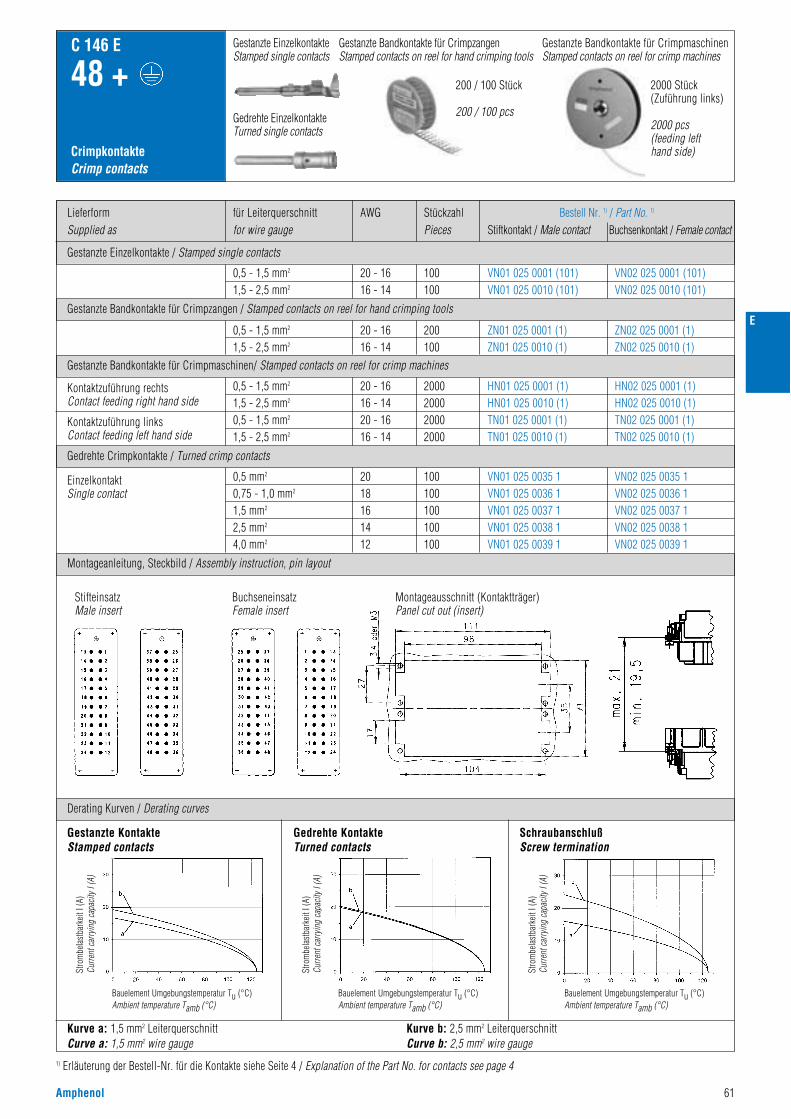
Amphenol 61
E
Gestanzte Einzelkontakte / Stamped single contacts
Gestanzte Bandkontakte für Crimpzangen / Stamped contacts on reel for hand crimping tools
Gestanzte Bandkontakte für Crimpmaschinen/ Stamped contacts on reel for crimp machines
LieferformSupplied as
AWGfür Leiterquerschnittfor wire gauge
StückzahlPieces
Bestell Nr. 1) / Part No. 1)
Stiftkontakt / Male contact Buchsenkontakt / Female contact
CrimpkontakteCrimp contacts
C 146 E
48 +
0,5 - 1,5 mm2
1,5 - 2,5 mm2
0,5 - 1,5 mm2
1,5 - 2,5 mm2
0,5 mm2
0,75 - 1,0 mm2
1,5 mm2
2,5 mm2
4,0 mm2
0,5 - 1,5 mm2
1,5 - 2,5 mm2
0,5 - 1,5 mm2
1,5 - 2,5 mm2
20 - 1616 - 1420 - 1616 - 14
2018161412
20 - 1616 - 14
20 - 1616 - 14
2000200020002000
100100100100100
200100
100100
HN01 025 0001 (1)HN01 025 0010 (1)TN01 025 0001 (1)TN01 025 0010 (1)
ZN01 025 0001 (1)ZN01 025 0010 (1)
VN01 025 0001 (101)VN01 025 0010 (101)
HN02 025 0001 (1)HN02 025 0010 (1)TN02 025 0001 (1)TN02 025 0010 (1)
ZN02 025 0001 (1)ZN02 025 0010 (1)
VN02 025 0001 (101)VN02 025 0010 (101)
Kontaktzuführung rechtsContact feeding right hand side
Kontaktzuführung linksContact feeding left hand side
EinzelkontaktSingle contact
Gedrehte Crimpkontakte / Turned crimp contacts
Montageanleitung, Steckbild / Assembly instruction, pin layout
Derating Kurven / Derating curves
Gestanzte Bandkontakte für CrimpmaschinenStamped contacts on reel for crimp machines
200 / 100 Stück
200 / 100 pcs
2000 Stück(Zuführung links)
2000 pcs(feeding lefthand side)
Gestanzte EinzelkontakteStamped single contacts
Gestanzte Bandkontakte für CrimpzangenStamped contacts on reel for hand crimping tools
Gedrehte EinzelkontakteTurned single contacts
Kurve a: 1,5 mm2 LeiterquerschnittCurve a: 1,5 mm2 wire gauge
Kurve b: 2,5 mm2 LeiterquerschnittCurve b: 2,5 mm2 wire gauge
Gestanzte KontakteStamped contacts
SchraubanschlußScrew termination
StifteinsatzMale insert
BuchseneinsatzFemale insert
Montageausschnitt (Kontaktträger)Panel cut out (insert)
Gedrehte KontakteTurned contacts
1) Erläuterung der Bestell-Nr. für die Kontakte siehe Seite 4 / Explanation of the Part No. for contacts see page 4
VN01 025 0035 1VN01 025 0036 1VN01 025 0037 1VN01 025 0038 1VN01 025 0039 1
VN02 025 0035 1VN02 025 0036 1VN02 025 0037 1VN02 025 0038 1VN02 025 0039 1
Stro
mbe
last
bark
eit I
(A)
Curre
nt c
arry
ing
capa
city
I (A
)
Bauelement Umgebungstemperatur Tu (°C)Ambient temperature Tamb (°C)
Stro
mbe
last
bark
eit I
(A)
Curre
nt c
arry
ing
capa
city
I (A
)
Bauelement Umgebungstemperatur Tu (°C)Ambient temperature Tamb (°C)
Stro
mbe
last
bark
eit I
(A)
Curre
nt c
arry
ing
capa
city
I (A
)
Bauelement Umgebungstemperatur Tu (°C)Ambient temperature Tamb (°C)
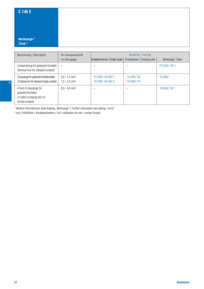
62 Amphenol
E
Werkzeuge 1)
Tools 1)
C 146 E
1) Weitere Informationen siehe Katalog „Werkzeuge“ / Further information see catalog „Tools“2) Incl. Prüfstiftset + Kontaktaufnahme / incl. calibration pin set + contact locator
Bezeichnung / Description
Lösewerkzeug für gestanzte KontakteRemoval tool for stamped contacts
– – – FG 0200 146 1
0,5 - 1,5 mm2
1,5 - 2,5 mm2
TA 0004 146 000 1TA 0005 146 000 3
TA 0000 163TA 0000 141
TA 0000
0,5 - 4,0 mm2 – – TB 0600 146 2)
Crimpzange für gestanzte EinzelkontakteCrimping tool for stamped single contacts
4-Kerb Crimpzange für gedrehte Kontakte4-indent crimping tool forturned contacts
für Leiterquerschnittfor wire gauge
Bestell Nr. / Part No.Kontaktaufnahme / Contact locator Crimpbacken / Crimping dies Werkzeuge / Tools
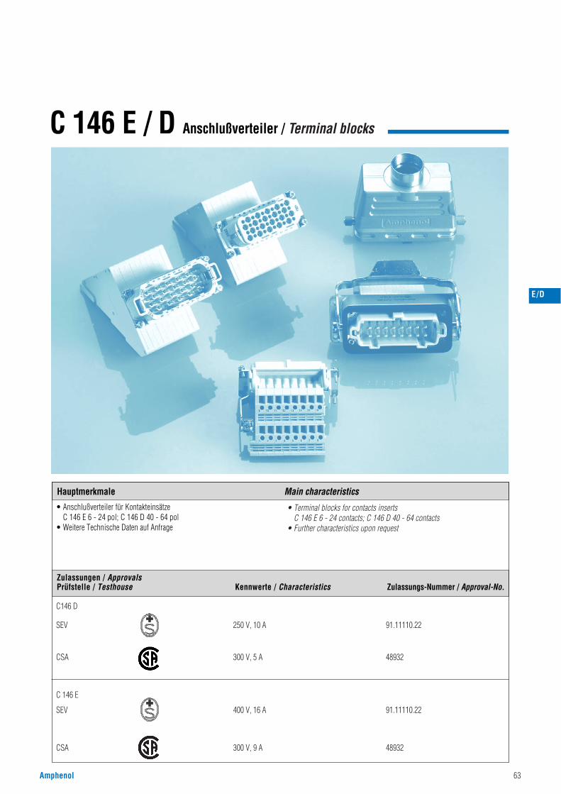
Amphenol 63
C 146 E / D Anschlußverteiler / Terminal blocks
Hauptmerkmale Main characteristics
E/D
Hauptmerkmale Main characteristics
Zulassungen / ApprovalsPrüfstelle / Testhouse Kennwerte / Characteristics Zulassungs-Nummer / Approval-No.
• Anschlußverteiler für KontakteinsätzeC 146 E 6 - 24 pol; C 146 D 40 - 64 pol
• Weitere Technische Daten auf Anfrage
• Terminal blocks for contacts inserts C 146 E 6 - 24 contacts; C 146 D 40 - 64 contacts
• Further characteristics upon request
C146 D
SEV 250 V, 10 A 91.11110.22
CSA 300 V, 5 A 48932
C 146 E
SEV 400 V, 16 A 91.11110.22
CSA 300 V, 9 A 48932
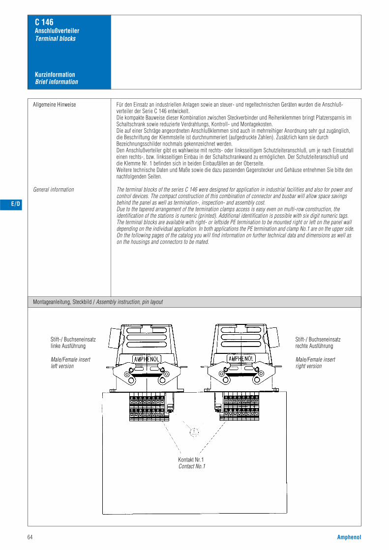
64 Amphenol
KurzinformationBrief information
C 146 AnschlußverteilerTerminal blocks
Allgemeine Hinweise
General information
Für den Einsatz an industriellen Anlagen sowie an steuer- und regeltechnischen Geräten wurden die Anschluß-verteiler der Serie C 146 entwickelt.Die kompakte Bauweise dieser Kombination zwischen Steckverbinder und Reihenklemmen bringt Platzersparnis imSchaltschrank sowie reduzierte Verdrahtungs, Kontroll- und Montagekosten.Die auf einer Schräge angeordneten Anschlußklemmen sind auch in mehrreihiger Anordnung sehr gut zugänglich,die Beschriftung der Klemmstelle ist durchnummeriert (aufgedruckte Zahlen). Zusätzlich kann sie durchBezeichnungsschilder nochmals gekennzeichnet werden.Den Anschlußverteiler gibt es wahlweise mit rechts- oder linksseitigem Schutzleiteranschluß, um je nach Einsatzfalleinen rechts-, bzw. linksseitigen Einbau in der Schaltschrankwand zu ermöglichen. Der Schutzleiteranschluß unddie Klemme Nr. 1 befinden sich in beiden Einbaufällen an der Oberseite.Weitere technische Daten und Maße sowie die dazu passenden Gegenstecker und Gehäuse entnehmen Sie bitte dennachfolgenden Seiten.
The terminal blocks of the series C 146 were designed for application in industrial facilities and also for power andcontrol devices. The compact construction of this combination of connector and busbar will allow space savingsbehind the panel as well as termination-, inspection- and assembly cost.Due to the tapered arrangement of the termination clamps access is easy even on multi-row construction, theidentification of the stations is numeric (printed). Additional identification is possible with six digit numeric tags.The terminal blocks are available with right- or leftside PE termination to be mounted right or left on the panel walldepending on the individual application. In both applications the PE termination and clamp No.1 are on the upper side.On the following pages of the catalog you will find information on further technical data and dimensions as well ason the housings and connectors to be mated.
Montageanleitung, Steckbild / Assembly instruction, pin layout
E/D
Stift-/ Buchseneinsatzlinke Ausführung
Male/Female insertleft version
Stift-/ Buchseneinsatzrechte Ausführung
Male/Female insertright version
Kontakt Nr.1Contact No.1
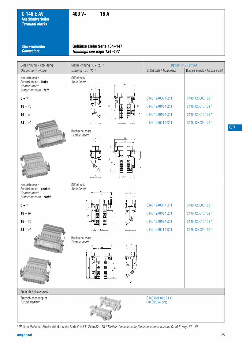
Amphenol 65
Bezeichnung - AbbildungDescription - Figure
Maßzeichnung 6 + 1)
Drawing 6 + 1)
Bestell Nr. / Part No.Stifteinsatz / Male insert Buchseneinsatz / Female insert
C 146 E AVAnschlußverteilerTerminal blocks
SteckverbinderConnectors
KontakteinsatzSchutzkontakt - linksContact insert protection earth - left
6 +
10 +
16 +
24 +
Gehäuse siehe Seite 134–147Housings see page 134–147
400 V~ 16 A
C146 12A006 102 1
C146 12A010 102 1
C146 12A016 102 1
C146 12A024 102 1
C146 12B006 102 1
C146 12B010 102 1
C146 12B016 102 1
C146 12B024 102 1
C146 12A006 152 1
C146 12A010 152 1
C146 12A016 152 1
C146 12A024 152 1
C146 N21 040 E1 X(10 Stk./10 pcs)
C146 12B006 152 1
C146 12B010 152 1
C146 12B016 152 1
C146 12B024 152 1
KontakteinsatzSchutzkontakt - rechtsContact insert protection earth - right
6 +
10 +
16 +
24 +
E/D
Zubehör / Accesories
TragschienenadapterFixing element
1) Weitere Maße der Steckverbinder siehe Serie C146 E, Seite 52 - 58 / Further dimensions for the connectors see series C146 E, page 52 - 58
StifteinsatzMale insert
BuchseneinsatzFemale insert
StifteinsatzMale insert
BuchseneinsatzFemale insert
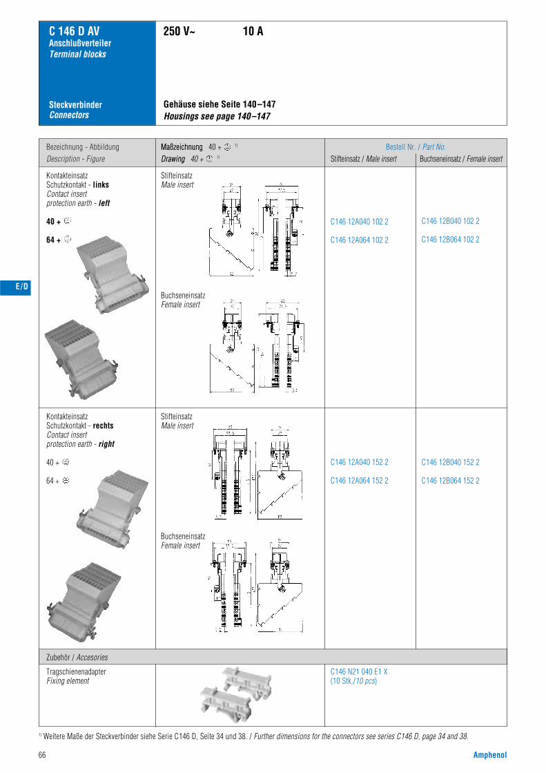
C 146 D AVAnschlußverteilerTerminal blocks
SteckverbinderConnectors
Gehäuse siehe Seite 140–147 Housings see page 140–147
250 V~ 10 A
Bezeichnung - AbbildungDescription - Figure
MaßzeichnungDrawing
Bestell Nr. / Part No.Stifteinsatz / Male insert Buchseneinsatz / Female insert
KontakteinsatzSchutzkontakt - linksContact insert protection earth - left
40 +
64 +
C146 12A040 102 2
C146 12A064 102 2
C146 12B040 102 2
C146 12B064 102 2
C146 12A040 152 2
C146 12A064 152 2
C146 12B040 152 2
C146 12B064 152 2
66 Amphenol
Maßzeichnung 40 + 1)
Drawing 40 + 1)
C146 N21 040 E1 X(10 Stk./10 pcs)
E/D
Zubehör / Accesories
TragschienenadapterFixing element
1) Weitere Maße der Steckverbinder siehe Serie C146 D, Seite 34 und 38. / Further dimensions for the connectors see series C146 D, page 34 and 38.
StifteinsatzMale insert
BuchseneinsatzFemale insert
StifteinsatzMale insert
BuchseneinsatzFemale insert
KontakteinsatzSchutzkontakt - rechtsContact insert protection earth - right
40 +
64 +
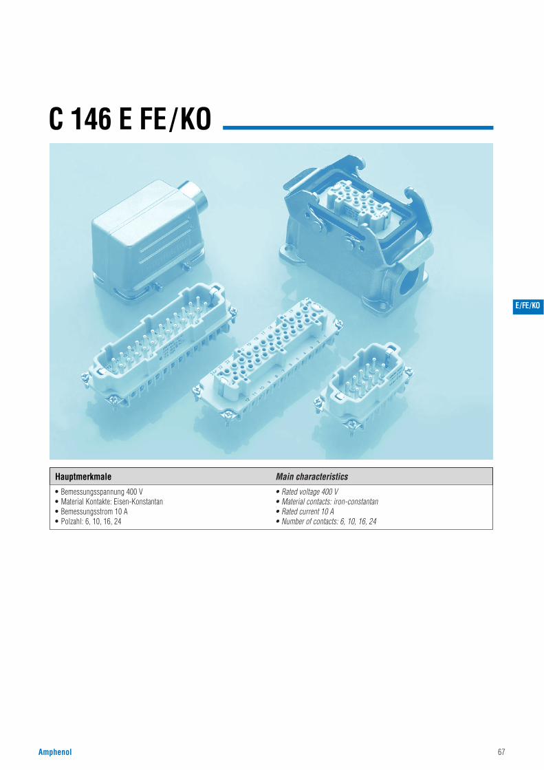
Amphenol 67
C 146 E FE/KO
E/FE/KO
Hauptmerkmale Main characteristics
• Bemessungsspannung 400 V• Material Kontakte: Eisen-Konstantan• Bemessungsstrom 10 A• Polzahl: 6, 10, 16, 24
• Rated voltage 400 V• Material contacts: iron-constantan• Rated current 10 A• Number of contacts: 6, 10, 16, 24
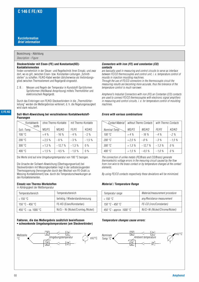
68 Amphenol
Bezeichnung - AbbildungDescription - Figure
C 146 E FE/KO
KurzinformationBrief information
Steckverbinder mit Eisen-(FE) und Konstantan(KO)-Kontaktelementenfinden vornehmlich in der Steuer- und Regeltechnik ihren Einsatz, und zwardort, wo es gilt, zwischen Eisen- bzw. Konstantan-Leitungen „Schnitt-stellen“ zu schaffen. FE/KO-Kabel werden üblicherweise als Verbindungs-glied zwischen Thermoelement und Regelgerät eingesetzt.
Z. B. : Messen und Regeln der Temperatur in Kunststoff-SpritzformenSpritzformen (Heißkanal-Anspritzung) mittels Thermofühler undelektronischem Regelgerät.
Durch das Einbringen von FE/KO-Steckverbindern in die „Thermofühler-leitung“ werden die Meßergebnisse verfeinert, d. h. die Regelungenauigkeitwird stark reduziert.
Soll-Wert-Abweichung bei verschiedenen Kontaktwerkstoff-Paarungen
Die Werte sind auf eine Umgebungstemperatur von 100 °C bezogen.
Die Ursache der Sollwert-Abweichung (Übertragungsverlust) beiSteckverbindern mit Messingkontakten liegt in der selbsterzeugendenThermospannung (hervorgerufen durch den Wechsel von FE-Draht zuMessing-Kontaktelement) bzw. durch die Temperaturschwankungen an den Kontaktelementen.
Einsatz von Thermo-Werkstoffenin Abhängigkeit der Meßtemperatur
Faktoren, die das Meßergebnis zusätzlich beeinflussen• schwankende Umgebungstemperaturen (am Steckverbinder)
Connectors with iron (FE) and constantan (CO)contactsare basically used in measuring and control circuits to serve as interfacebetween FE/CO thermocouples and control unit, i. e. temperature control ofmoulds in injection moulding machines.Through the use of FE/CO connectors in the thermocouple circuit themeasuring results are becoming more accurate, thus the tolerance of thetemperature control is much narrower.
Amphenol’s Industial Connectors with iron (FE) an Contantan (CO) contactsare used to connect FE/CO thermocouples with electronic signal amplifiersin measuring and control circuits, i. e. for temperature control of mouldingmachines.
Errors with various combinations
The connection of unlike metals (FE/Brass and CO/Brass) generatethermoelectric voltage errors in the mesuring circuit caused by the flowfrom iron wire to the brass contact or by temperature changes at the contactelements.
By using FE/CO contacts respectively these deviations will be minimized.
Material / Temperature Range
Temperature changes cause errors:
Soll.-Temp.
100 °C
200 °C
300 °C
400 °C
+ 4 %
+ 2,5 %
+ 1,3 %
+ 1,5 %
- 16 %
- 8 %
- 12,7 %
- 4,5 %
- 4 %
- 3 %
- 1,3 %
- 1,0 %
- 2 %
- 1,5 %
0 %
0 %
Kontaktwerk-stoffe
Temperaturbereich
< 150 °C
150 °C - 450 °C
450 °C - ca. 1000 °C
Temperaturbereich
beliebig / Wiederstandsmessung
FE-KO (Eisen/Konstantan)
Ni/Cr - Ni (Nickel/Cromleg./Nickel)
Temperatur range
< 150 °C
150 °C - 450 °C
450 °C - approx. 1000 °C
Material/measurement procedure
any/Resistance measurement
FE-CO (iron/Constantan)
Ni/Cr-Ni (Nickel/Chrome/Nickel)
ohne Thermo-Kontakte
MS/FS MS/KO
mit Thermo-Kontakte
FE/FE KO/KO Nominal Temp.
100 °C
200 °C
300 °C
400 °C
+ 4 %
+ 2,5 %
+ 1,3 %
+ 1,5 %
- 16 %
- 8 %
- 12,7 %
- 4,5 %
- 4 %
- 3 %
- 1,3 %
- 1,0 %
- 2 %
- 1,5 %
0 %
0 %
Contact Material without Thermo Contacts
MS/FS MS/KO
with Thermo Contacts
FE/FE KO/KO
Meßstelle°C
NominaleTemp.°CUmgebungstemperatur Ambient temperaturemV/°C
mV/°C
E/FE/KO
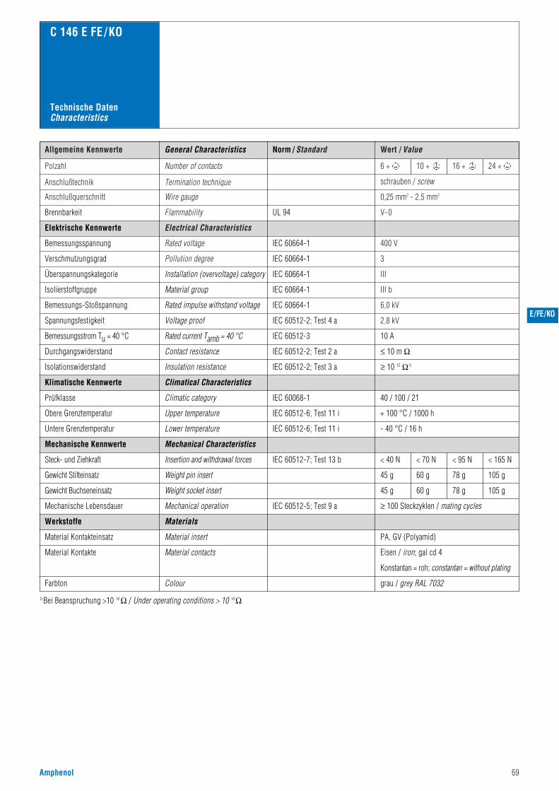
Amphenol 69
Norm / Standard Wert / ValueAllgemeine Kennwerte
Polzahl
400 V
3
III
III b
6,0 kV
2,8 kV
Number of contacts
Anschlußtechnik Termination technique
V- 0
schrauben / screw
Anschlußquerschnitt Wire gauge 0,25 mm2 - 2,5 mm2
6 + 10 + 16 + 24 +
Flammability
Electrical Characteristics
Rated voltage
Pollution degree
C 146 E FE /KO
Installation (overvoltage) category
Material group
Rated impulse withstand voltage
Voltage proof
IEC 60664-1
IEC 60664-1
IEC 60664-1
IEC 60664-1
IEC 60664-1
IEC 60512-2; Test 4 a
UL 94Brennbarkeit
Elektrische Kennwerte
Bemessungsspannung
Verschmutzungsgrad
Überspannungskategorie
Isolierstoffgruppe
Bemessungs-Stoßspannung
Spannungsfestigkeit
10 AIEC 60512-3Rated current Tamb = 40 °CBemessungsstrom Tu = 40 °C
General Characteristics
Technische DatenCharacteristics
grau / grey RAL 7032
≤ 10 m ΩIEC 60512-2; Test 2 a
IEC 60068-1
Contact resistance
Climatical Characteristics
Climatic category
Material insert
Material contacts
40 / 100 / 21
< 40 N < 70 N < 95 N < 165 N
45 g
45 g
60 g
60 g
78 g
78 g
105 g
105 g
PA, GV (Polyamid)
Eisen / iron; gal cd 4
Konstantan = roh; constantan = without plating
Durchgangswiderstand
≥ 10 12 Ω1)IEC 60512-2; Test 3 aInsulation resistanceIsolationswiderstand
Klimatische Kennwerte
Prüfklasse
IEC 60512-7; Test 13 b
IEC 60512-5; Test 9 a
Mechanical Characteristics
Insertion and withdrawal forces
Weight pin insert
Weight socket insert
Mechanical operation ≥ 100 Steckzyklen / mating cycles
Mechanische Kennwerte
Steck- und Ziehkraft
Gewicht Stifteinsatz
Gewicht Buchseneinsatz
Mechanische Lebensdauer
Werkstoffe
Material Kontakteinsatz
Material Kontakte
Farbton
1) Bei Beanspruchung >10 10 Ω / Under operating conditions > 10 10 Ω
Colour
Materials
IEC 60512-6; Test 11 i + 100 °C / 1000 h
IEC 60512-6; Test 11 i - 40 °C / 16 h
Obere Grenztemperatur
Untere Grenztemperatur
Upper temperature
Lower temperature
E/FE/KO
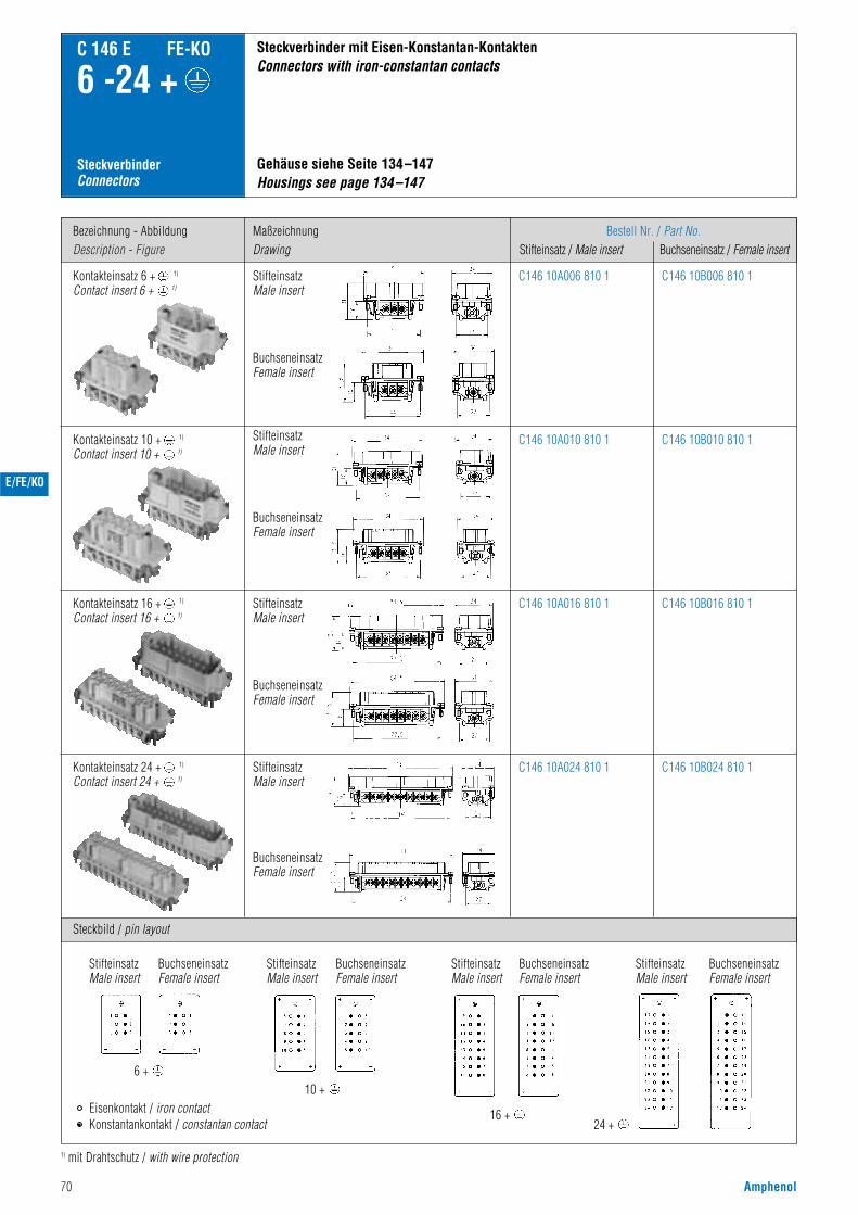
70 Amphenol
Bezeichnung - AbbildungDescription - Figure
Steckbild / pin layout
MaßzeichnungDrawing
Bestell Nr. / Part No.Stifteinsatz / Male insert Buchseneinsatz / Female insert
C 146 E FE-KO
6 -24 +
SteckverbinderConnectors
Kontakteinsatz 6 + 1)
Contact insert 6 + 1)
Gehäuse siehe Seite 134–147Housings see page 134–147
Steckverbinder mit Eisen-Konstantan-KontaktenConnectors with iron-constantan contacts
C146 10A006 810 1 C146 10B006 810 1
1) mit Drahtschutz / with wire protection
Kontakteinsatz 10 + 1)
Contact insert 10 + 1)C146 10A010 810 1
C146 10A016 810 1
C146 10A024 810 1
C146 10B010 810 1
C146 10B016 810 1
C146 10B024 810 1
E/FE/KO
StifteinsatzMale insert
BuchseneinsatzFemale insert
StifteinsatzMale insert
BuchseneinsatzFemale insert
StifteinsatzMale insert
BuchseneinsatzFemale insert
Kontakteinsatz 16 + 1)
Contact insert 16 + 1)
BuchseneinsatzFemale insert
StifteinsatzMale insert
Kontakteinsatz 24 + 1)
Contact insert 24 + 1)
StifteinsatzMale insert
BuchseneinsatzFemale insert
StifteinsatzMale insert
BuchseneinsatzFemale insert
StifteinsatzMale insert
BuchseneinsatzFemale insert
StifteinsatzMale insert
6 +10 +
16 +24 +
Eisenkontakt / iron contactKonstantankontakt / constantan contact
BuchseneinsatzFemale insert
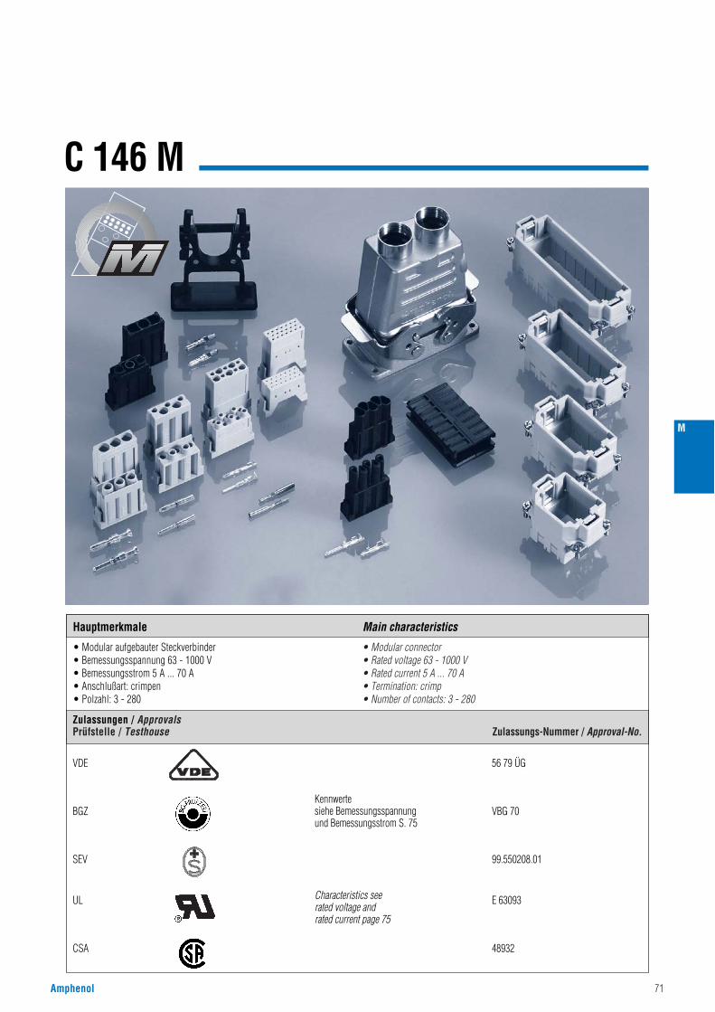
Amphenol 71
C 146 M
• Modular aufgebauter Steckverbinder• Bemessungsspannung 63 - 1000 V• Bemessungsstrom 5 A ... 70 A• Anschlußart: crimpen• Polzahl: 3 - 280
• Modular connector• Rated voltage 63 - 1000 V• Rated current 5 A ... 70 A• Termination: crimp• Number of contacts: 3 - 280
M
VDE 56 79 ÜG
BGZ VBG 70
SEV 99.550208.01
UL E 63093
CSA 48932
Kennwertesiehe Bemessungsspannungund Bemessungsstrom S. 75
Characteristics seerated voltage andrated current page 75
Zulassungen / ApprovalsPrüfstelle / Testhouse Zulassungs-Nummer / Approval-No.
Hauptmerkmale Main characteristics
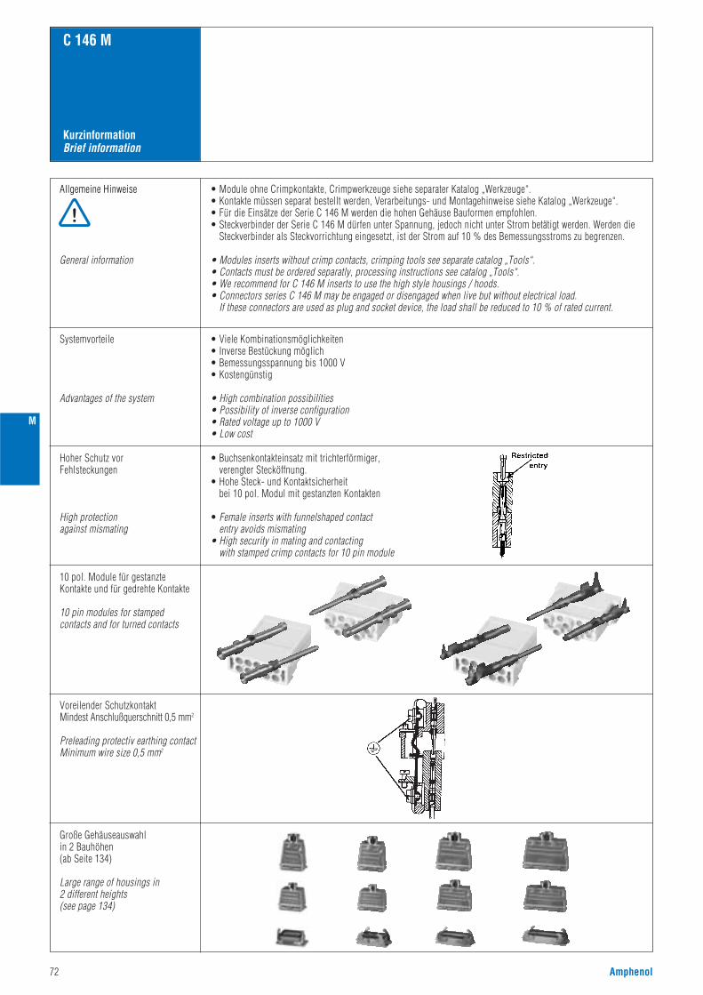
72 Amphenol
M
KurzinformationBrief information
C 146 M
Allgemeine Hinweise
General information
• Module ohne Crimpkontakte, Crimpwerkzeuge siehe separater Katalog „Werkzeuge“.• Kontakte müssen separat bestellt werden, Verarbeitungs- und Montagehinweise siehe Katalog „Werkzeuge“.• Für die Einsätze der Serie C 146 M werden die hohen Gehäuse Bauformen empfohlen.• Steckverbinder der Serie C 146 M dürfen unter Spannung, jedoch nicht unter Strom betätigt werden. Werden die
Steckverbinder als Steckvorrichtung eingesetzt, ist der Strom auf 10 % des Bemessungsstroms zu begrenzen.
• Modules inserts without crimp contacts, crimping tools see separate catalog „Tools“.• Contacts must be ordered separatly, processing instructions see catalog „Tools“.• We recommend for C 146 M inserts to use the high style housings / hoods.• Connectors series C 146 M may be engaged or disengaged when live but without electrical load.
If these connectors are used as plug and socket device, the load shall be reduced to 10 % of rated current.
Systemvorteile
Advantages of the system
• Viele Kombinationsmöglichkeiten• Inverse Bestückung möglich• Bemessungsspannung bis 1000 V• Kostengünstig
• High combination possibilities• Possibility of inverse configuration• Rated voltage up to 1000 V• Low cost
Hoher Schutz vorFehlsteckungen
High protectionagainst mismating
• Buchsenkontakteinsatz mit trichterförmiger,verengter Stecköffnung.
• Hohe Steck- und Kontaktsicherheitbei 10 pol. Modul mit gestanzten Kontakten
• Female inserts with funnelshaped contactentry avoids mismating
• High security in mating and contactingwith stamped crimp contacts for 10 pin module
10 pol. Module für gestanzteKontakte und für gedrehte Kontakte
10 pin modules for stampedcontacts and for turned contacts
Voreilender SchutzkontaktMindest Anschlußquerschnitt 0,5 mm2
Preleading protectiv earthing contactMinimum wire size 0,5 mm2
Große Gehäuseauswahlin 2 Bauhöhen (ab Seite 134)
Large range of housings in2 different heights(see page 134)
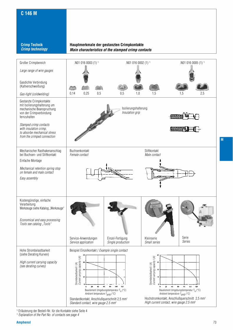
Amphenol 73
M
Crimp TechnikCrimp technology
C 146 M
Hauptmerkmale der gestanzten CrimpkontakteMain characteristics of the stamped crimp contacts
1) Erläuterung der Bestell-Nr. für die Kontakte siehe Seite 41) Explanation of the Part No. of contacts see page 4
Großer Crimpbereich
Large range of wire gauges
Gasdichte Verbindung(Kaltverschweißung)
Gas-tight (coldwelding)
Gestanzte Crimpkontakte mit Isolierungshalterung ummechanische Beanspruchung von der Crimpverbindungfernzuhalten
Stamped crimp contacts with insulation crimp,to absorbe mechanical stress from the crimped connection
Mechanischer Rasthakenanschlagbei Buchsen- und Stiftkontakt
Einfache Montage
Mechanical retention spring stop on female and male contact
Easy assembly
Kostengünstige, einfacheVerarbeitungWerkzeuge siehe Katalog „Werkzeuge“
Economical and easy processingTools see catalog „Tools“
Hohe Strombelastbarkeit(siehe Derating Kurven)
High current carrying capacity(see derating curves)
Beispiel Einzelkontakt / Example single contact
Standardkontakt, Anschlußquerschnitt 2,5 mm2
Standard contact, wire gauge 2.5 mm2
Hochstromkontakt, Anschlußquerschnitt 2,5 mm2
High current contact, wire gauge 2.5 mm2
.N01 016 0003 (1) 1)
0,14 0,25 0,5 0,5 1,0 1,5 1,5 2,5
.N01 016 0002 (1) 1) .N01 016 0005 (1) 1)
IsolierungshalterungInsulation grip
KleinserieSmall series
SerieSeries
BuchsenkontaktFemale contact
StiftkontaktMale contact
Service-AnwendungenService application
Einzel-FertigungSingle production
Stro
mbe
last
bark
eit I
(A)
Curre
nt c
arry
ing
capa
city
I (A
)
Bauelement Umgebungstemperatur Tu (°C)Ambient temperature Tamb (°C)
Stro
mbe
last
bark
eit I
(A)
Curre
nt c
arry
ing
capa
city
I (A
)
Bauelement Umgebungstemperatur Tu (°C)Ambient temperature Tamb (°C)
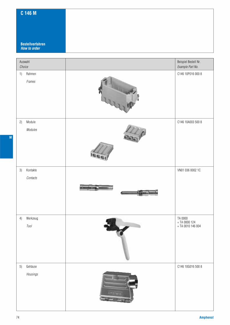
74 Amphenol
M
BestellverfahrenHow to order
C 146 M
1) Rahmen
Frames
AuswahlChoice
Beispiel Bestell Nr. Example Part No.
C146 10P016 000 8
2) Module
Modules
C146 10A003 500 8
3) Kontakte
Contacts
VN01 036 0002 1C
4) Werkzeug
Tool
TA 0000+ TA 0000 124+ TA 0010 146 004
5) Gehäuse
Housings
C146 10G016 500 8
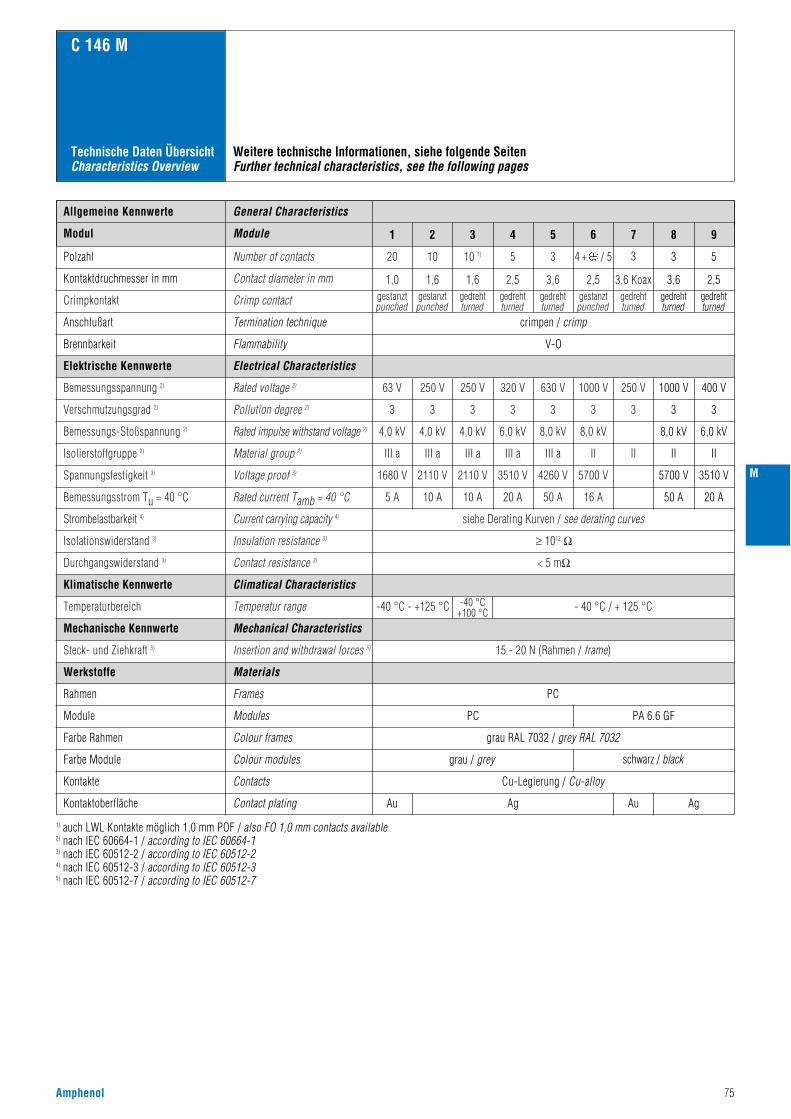
Amphenol 75
C 146 M
Technische Daten ÜbersichtCharacteristics Overview
Weitere technische Informationen, siehe folgende SeitenFurther technical characteristics, see the following pages
Allgemeine Kennwerte
Electrical Characteristics
Climatical Characteristics
Mechanical Characteristics
Elektrische Kennwerte
Klimatische Kennwerte
Mechanische Kennwerte
Werkstoffe Materials
General Characteristics
Polzahl
Kontaktdruchmesser in mm
Number of contacts
Contact diameter in mm
Crimpkontakt Crimp contact
20 10 10 1) 5 3 4 + / 5
1,61,0gestanztpunched
gestanztpunched
gedrehtturned
gedrehtturned
gedrehtturned
gestanztpunched
gedrehtturned
1,6 2,5 3,6 2,5 3,6 Koax
3
siehe Derating Kurven / see derating curves
≥ 1012 Ω
Bemessungsspannung 2)
Verschmutzungsgrad 2)
250 V63 V 250 V 320 V 630 V 1000 V 250 V
33 3 3 3 3 3
III aIII a III a III a III a II II
10 A5 A 10 A 20 A 50 A 16 A
2110 V1680 V 2110 V 3510 V 4260 V 5700 V
4,0 kV4,0 kV 4,0 kV 6,0 kV 8,0 kV 8,0 kV
Rated voltage 2)
Pollution degree 2)
Isolierstoffgruppe 2) Material group 2)
Rated impulse withstand voltage 2)
Voltage proof 3)
Bemessungs-Stoßspannung 2)
Spannungsfestigkeit 3)
Rated current Tamb = 40 °CBemessungsstrom Tu = 40 °C
Strombelastbarkeit 4)
Isolationswiderstand 3)
Current carrying capacity 4)
Insulation resistance 3)
-40 °C - +125 °C -40 °C+100 °C - 40 °C / + 125 °CTemperaturbereich Temperatur range
15 - 20 N (Rahmen / frame)Steck- und Ziehkraft 5) Insertion and withdrawal forces 5)
< 5 mΩDurchgangswiderstand 3) Contact resistance 3)
Modul 1 2 3 4 5 6 7 8 9
3 5
gedrehtturned
gedrehtturned
3,6 2,5
1000 V 400 V
3 3
II II
50 A 20 A
5700 V 3510 V
8,0 kV 6,0 kV
Module
Anschlußart Termination technique
Brennbarkeit Flammability V-O
Rahmen
Module
Frames
Modules PC
PC
PA 6.6 GF
Farbe Rahmen Colour frames
Farbe Module Colour modules
Kontakte Contacts
Kontaktoberfläche Contact plating
grau / grey schwarz / black
Au Au AgAg
grau RAL 7032 / grey RAL 7032
Cu-Legierung / Cu-alloy
crimpen / crimp
1) auch LWL Kontakte möglich 1,0 mm POF / also FO 1,0 mm contacts available2) nach IEC 60664-1 / according to IEC 60664-13) nach IEC 60512-2 / according to IEC 60512-24) nach IEC 60512-3 / according to IEC 60512-35) nach IEC 60512-7 / according to IEC 60512-7
M
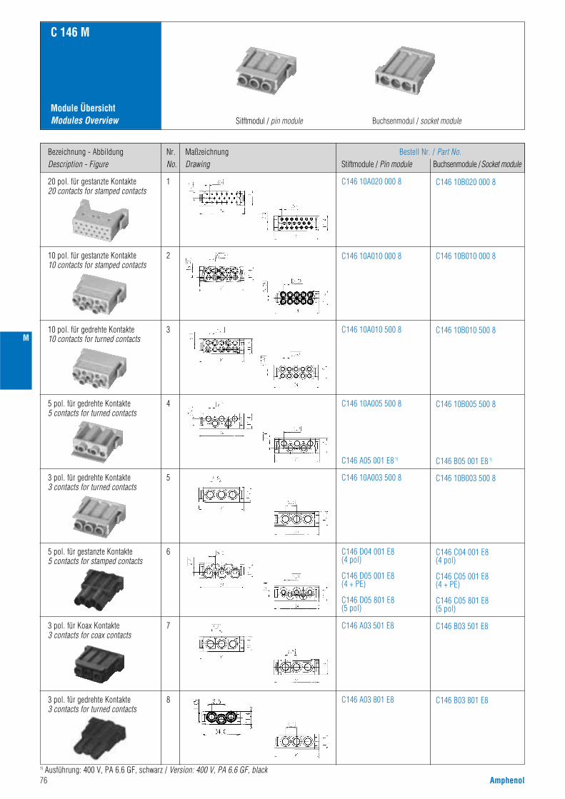
76 Amphenol
M
Module ÜbersichtModules Overview
C 146 M
Sitftmodul / pin module Buchsenmodul / socket module
Bezeichnung - AbbildungDescription - Figure
Nr.No.
MaßzeichnungDrawing
Bestell Nr. / Part No.Stiftmodule / Pin module Buchsenmodule /Socket module
C146 10A020 000 8 C146 10B020 000 820 pol. für gestanzte Kontakte20 contacts for stamped contacts
1
C146 10A010 000 8 C146 10B010 000 810 pol. für gestanzte Kontakte10 contacts for stamped contacts
2
C146 10A010 500 8 C146 10B010 500 810 pol. für gedrehte Kontakte10 contacts for turned contacts
3
C146 10A005 500 8
C146 A05 001 E8 1)
C146 10B005 500 8
C146 B05 001 E8 1)
5 pol. für gedrehte Kontakte5 contacts for turned contacts
4
C146 10A003 500 8 C146 10B003 500 83 pol. für gedrehte Kontakte3 contacts for turned contacts
3 pol. für gedrehte Kontakte3 contacts for turned contacts
5
C146 D04 001 E8(4 pol)
C146 D05 001 E8(4 + PE)
C146 D05 801 E8(5 pol)
C146 C04 001 E8(4 pol)
C146 C05 001 E8(4 + PE)
C146 C05 801 E8(5 pol)
5 pol. für gestanzte Kontakte5 contacts for stamped contacts
6
C146 A03 501 E8 C146 B03 501 E83 pol. für Koax Kontakte3 contacts for coax contacts
7
C146 A03 801 E8 C146 B03 801 E88
1) Ausführung: 400 V, PA 6.6 GF, schwarz / Version: 400 V, PA 6.6 GF, black
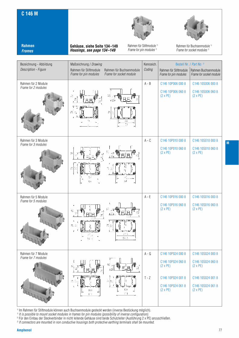
Amphenol 77
M
RahmenFrames
C 146 M
Rahmen für Stiftmodule 1)
Frame for pin modules 1)Rahmen für Buchsenmodule 1)
Frame for socket modules 1)
Bezeichnung - AbbildungDescription - Figure
Maßzeichnung / Drawing
Rahmen für StiftmoduleFrame for pin modules
Rahmen für BuchsenmoduleFrame for socket module
Kennzeich.Coding
Bestell Nr. / Part No. 2)
Rahmen für Stiftmodule Rahmen Buchsenmodule Frame for pin modules Frame for socket module
C146 10P006 000 8
C146 10P006 060 8(2 x PE)
C146 10S006 000 8
C146 10S006 060 8(2 x PE)
Rahmen für 2 ModuleFrame for 2 modules
A - B
Gehäuse, siehe Seite 134–149Housings, see page 134–149
C146 10P010 000 8
C146 10P010 060 8(2 x PE)
C146 10S010 000 8
C146 10S010 060 8(2 x PE)
Rahmen für 3 ModuleFrame for 3 modules
A - C
C146 10P016 000 8
C146 10P016 060 8(2 x PE)
C146 10S016 000 8
C146 10S016 060 8(2 x PE)
Rahmen für 5 ModuleFrame for 5 modules
A - E
C146 10P024 000 8
C146 10P024 060 8(2 x PE)
C146 10P024 001 8
C146 10P024 061 8(2 x PE)
C146 10S024 000 8
C146 10S024 060 8(2 x PE)
C146 10S024 001 8
C146 10S024 061 8(2 x PE)
Rahmen für 7 ModuleFrame for 7 modules
A - G
T - Z
1) Im Rahmen für Stiftmodule können auch Buchsenmodule gesteckt werden (inverse Bestückung möglich).1) It is possible to mount socket modules in frames for pin modules (possibility of inverse configuration).2) Für den Einbau der Steckverbinder in nicht leitende Gehäuse sind beide Schutzleiter (Ausführung 2 x PE) anzuschließen.2) If connectors are mounted in non conductive housings both protective earthing terminals shall be mounted.

78 Amphenol
Norm / Standard Wert / ValueAllgemeine Kennwerte
Polzahl
63 V
3
III
III a
4,0 KV
1,68 kV
siehe Derating Kurven / see derating curves
Number of contacts
Anschlußtechnik Termination technique
V-0
crimpen / crimp
Anschlußquerschnitt Wire gauge 0,09 - 0,5 mm2 (AWG 28 - 20)
20
Flammability
Electrical Characteristics
Rated voltage
Pollution degree
C 146 M
20 pol
Installation (overvoltage) category
Material group
Rated impulse withstand voltage
Voltage proof
IEC 60664-1
IEC 60664-1
IEC 60664-1
IEC 60664-1
IEC 60664-1
IEC 60512-2; Test 4 a
UL 94
IEC 60512-3; Test 5 b
IEC 60512-5; Test 9 a
Current carrying capacity
Mechanical operation
Insert
≥ 500 Steckzyklen / mating cycles
PC
grau / grey
Elektrische Kennwerte
Bemessungsspannung
Verschmutzungsgrad
Brennbarkeit
Überspannungskategorie
Isolierstoffgruppe
Bemessungs-Stoßspannung
Spannungsfestigkeit
Strombelastbarkeit
≤ 5 mΩIEC 60512-2; Test 2 aContact resistanceDurchgangswiderstand
≥ 10 12 Ω 2)IEC 60512-2; Test 3 aInsulation resistanceIsolationswiderstand
> 2,4 mmIEC 60664-1ClearanceLuftstrecke
> 2,4 mmIEC 60664-1CreepageKriechstrecke
IEC 60068-1
IEC 60512-7; Test 13 b
Climatical Characteristics
Climatic category
Mechanical Characteristics
Insertion and withdrawal forces 1)
40 / 125 / 21
Klimatische Kennwerte
Prüfklasse
IEC 60512-6; Test 11 iUpper temperature
Lower temperature
+ 125 °C / 1000 hObere Grenztemperatur
Untere Grenztemperatur IEC 60512-6; Test 11 i - 40 °C / 16 h
10 - 15 N
Mechanische Kennwerte
Steck- und Ziehkraft 1)
Mechanische Lebensdauer
Werkstoffe
Kontakteinsatz
Contacts male / female CuZn (Messing/brass) / CuSn (Bronze/bronce)Kontakte Stift / Buchse
Contact plating AuKontaktoberfläche
Farbe Colour
Materials
General Characteristics
1) für ein Modul / for one module 2) bei Beanspruchung >10 10 Ω / under operating condition >10 10 Ω
Technische DatenCharacteristics
Derating Kurven / Derating curves
0,25 mm2 0,5 mm2 KurveCurve
PolzahlContacts
RahmenFrame
a 20 2 Module
2 Module
3 Module
5 Module
7 Module
40
60
100
140
b
c
d
e
Stro
mbe
last
bark
eit I
(A)
Curre
nt c
arry
ing
capa
city
I (A
)
Bauelement Umgebungstemperatur Tu (°C)Ambient temperature Tamb (°C)
Stro
mbe
last
bark
eit I
(A)
Curre
nt c
arry
ing
capa
city
I (A
)
Bauelement Umgebungstemperatur Tu (°C)Ambient temperature Tamb (°C)
M
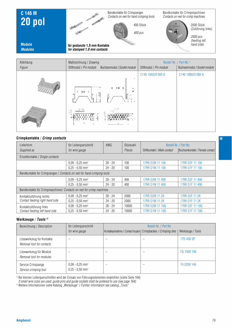
Amphenol 79
M
Einzelkontakte / Single contacts
Bandkontakte für Crimpzangen / Contacts on reel for hand crimping tools
Bandkontakte für Crimpmaschinen/ Contacts on reel for crimp machines
LieferformSupplied as
AWGfür Leiterquerschnittfor wire gauge
für Leiterquerschnittfor wire gauge
StückzahlPieces
Bestell Nr. / Part No.Stiftkontakt / Male contact Buchsenkontakt / Female contact
Bestell Nr. / Part No.Kontaktaufnahme / Contact locator Crimpbacken / Crimping dies Werkzeuge / Tools
ModuleModules
C 146 M
20 pol
0,09 - 0,25 mm2
0,25 - 0,50 mm2
0,09 - 0,25 mm2
0,25 - 0,50 mm2
–
–
0,09 - 0,25 mm2
0,25 - 0,50 mm2
–
–
–
– 17D 438 SP
FG 1000 146
TA 0200 146
–
–
0,09 - 0,25 mm2
0,25 - 0,50 mm2
0,09 - 0,25 mm2
0,25 - 0,50 mm2
28 - 2424 - 2028 - 2424 - 20
28 - 2424 - 20
28 - 2424 - 20
200020001000010000
400400
100100
17RR D2M 11 2K17RR D1M 11 2K17RR D2M 11 10G17RR D1M 11 10G
17RR D2M 11 40017RR D1M 11 400
17RR D2M 11 10017RR D1M 11 100
17RR D2F 11 2K17RR D1F 11 2K17RR D2F 11 10G17RR D1F 11 10G
17RR D2F 11 40017RR D1F 11 400
17RR D2F 11 10017RR D1F 11 100
Kontaktzuführung rechtsContact feeding right hand side
Kontaktzuführung linksContact feeding left hand side
Bezeichnung / Description
Lösewerkzeug für KontakteRemoval tool for contacts
Lösewerkzeug für ModuleRemoval tool for modules
Service CrimpzangeService crimping tool
Bandkontakte für CrimpmaschinenContacts on reel for crimp machines
400 Stück
400 pcs
2000 Stück(Zuführung links)
2000 pcs(feeding lefthand side)
Bandkontakte für CrimpzangenContacts on reel for hand crimping tools
für gestanzte 1,0 mm Kontaktefor stamped 1,0 mm contacts
AbbildungFigure
Maßzeichnung / DrawingStiftmodul / Pin module Buchsenmodul /Socket module
Bestell Nr. / Part No.1)
Stiftmodul / Pin module Buchsenmodul /Socket module
Crimpkontakte / Crimp contacts
Werkzeuge / Tools 2)
C146 10A020 000 8 C146 10B020 000 8
1) Bei kleinen Leiterquerschnitten wird der Einsatz von Führungselementen empfohlen (siehe Seite 164)If small wire sizes are used, guide pins and guide sockets shall be prefered to use (see page 164)
2) Weitere Informationen siehe Katalog „Werkzeuge“ / Further information see catalog „Tools“

Norm / Standard Wert / ValueAllgemeine Kennwerte
Polzahl
250 V
3
III
III a
4,0 KV
2,11 kV
siehe Derating Kurven / see derating curves
Number of contacts
Anschlußtechnik Termination technique
V-0
crimpen / crimp
Anschlußquerschnitt Wire gauge 0,14 - 2,5 mm2 (AWG 26 - 14)
10
Flammability
Electrical Characteristics
Rated voltage
Pollution degree
C 146 M
10 pol
Installation (overvoltage) category
Material group
Rated impulse withstand voltage
Voltage proof
IEC 60664-1
IEC 60664-1
IEC 60664-1
IEC 60664-1
IEC 60664-1
IEC 60512-2; Test 4 a
UL 94
IEC 60512-3; Test 5 b
IEC 60512-5; Test 9 a
Current carrying capacity
Mechanical operation
Module
≥ 500 Steckzyklen / mating cycles
PC
grau / grey
Elektrische Kennwerte
Bemessungsspannung
Verschmutzungsgrad
Brennbarkeit
Überspannungskategorie
Isolierstoffgruppe
Bemessungs-Stoßspannung
Spannungsfestigkeit
Strombelastbarkeit
≤ 5 mΩIEC 60512-2; Test 2 aContact resistanceDurchgangswiderstand
≥ 10 12 Ω 2)IEC 60512-2; Test 3 aInsulation resistanceIsolationswiderstand
IEC 60068-1
IEC 60512-6; Test 11 i
IEC 60512-6; Test 11 i
IEC 60512-7; Test 13 b
Climatical Characteristics
Climatic category
Mechanical Characteristics
Insertion and withdrawal forces 1)
40 / 125 / 21
Klimatische Kennwerte
Prüfklasse
Upper temperature
Lower temperature
+ 125 °C / 1000 hObere Grenztemperatur
Untere Grenztemperatur - 40 °C / 16 h
20 - 25 N
Mechanische Kennwerte
Steck- und Ziehkraft 1)
Mechanische Lebensdauer
Werkstoffe
Modul
Male contact CuZn (Messing/brass)
CuSn (Bronze/bronce)
Stiftkontakt
Female contactBuchsenkontakt
Contact plating AgKontaktoberfläche
Farbe Colour
Materials
General Characteristics
1) für ein Modul / for one module 2) bei Beanspruchung >10 10 Ω / under operating condition >10 10 Ω
Technische DatenCharacteristics
Module für gestanzte KontakteModules for stamped contacts
> 4,3 mmIEC 60664-1Clearance / CreepageLuftstrecke / Kriechstrecke
Derating Kurven / Derating curves
0,5 mm2 1,5 mm2 KurveCurve
PolzahlContacts
RahmenFrame
a 10 2 Module
2 Module
3 Module
5 Module
7 Module
20
30
50
70
b
c
d
e
80 Amphenol
Stro
mbe
last
bark
eit I
(A)
Curre
nt c
arry
ing
capa
city
I (A
)
Bauelement Umgebungstemperatur Tu (°C)Ambient temperature Tamb (°C)
Stro
mbe
last
bark
eit I
(A)
Curre
nt c
arry
ing
capa
city
I (A
)
Bauelement Umgebungstemperatur Tu (°C)Ambient temperature Tamb (°C)
M
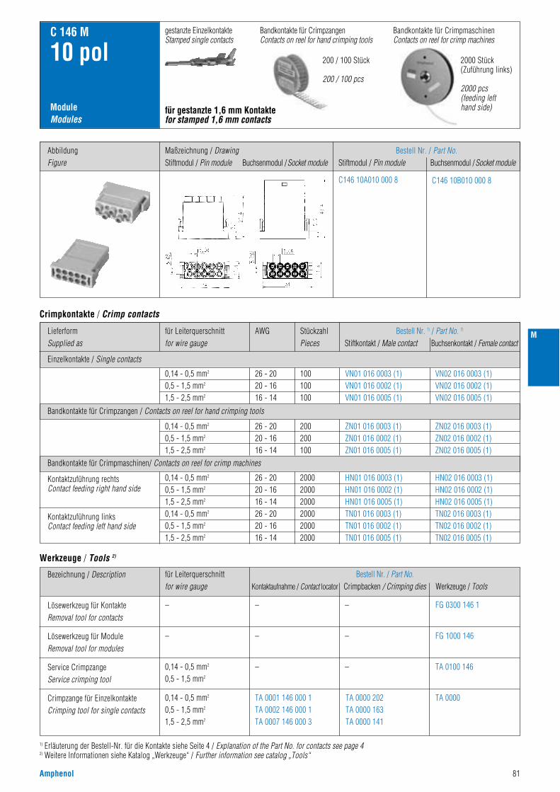
Amphenol 81
M
Einzelkontakte / Single contacts
Bandkontakte für Crimpzangen / Contacts on reel for hand crimping tools
Bandkontakte für Crimpmaschinen/ Contacts on reel for crimp machines
LieferformSupplied as
AWGfür Leiterquerschnittfor wire gauge
StückzahlPieces
Bestell Nr. 1) / Part No. 1)
Stiftkontakt / Male contact Buchsenkontakt / Female contact
ModuleModules
C 146 M
10 pol
0,14 - 0,5 mm2
0,5 - 1,5 mm2
1,5 - 2,5 mm2
0,14 - 0,5 mm2
0,5 - 1,5 mm2
1,5 - 2,5 mm2
0,14 - 0,5 mm2
0,5 - 1,5 mm2
1,5 - 2,5 mm2
0,14 - 0,5 mm2
0,5 - 1,5 mm2
1,5 - 2,5 mm2
26 - 2020 - 1616 - 1426 - 2020 - 1616 - 14
26 - 2020 - 1616 - 14
26 - 2020 - 1616 - 14
200020002000200020002000
200200100
100100100
HN01 016 0003 (1)HN01 016 0002 (1)HN01 016 0005 (1)TN01 016 0003 (1)TN01 016 0002 (1)TN01 016 0005 (1)
ZN01 016 0003 (1)ZN01 016 0002 (1)ZN01 016 0005 (1)
VN01 016 0003 (1)VN01 016 0002 (1)VN01 016 0005 (1)
HN02 016 0003 (1)HN02 016 0002 (1)HN02 016 0005 (1)TN02 016 0003 (1)TN02 016 0002 (1)TN02 016 0005 (1)
ZN02 016 0003 (1)ZN02 016 0002 (1)ZN02 016 0005 (1)
VN02 016 0003 (1)VN02 016 0002 (1)VN02 016 0005 (1)
Kontaktzuführung rechtsContact feeding right hand side
Kontaktzuführung linksContact feeding left hand side
Bandkontakte für CrimpmaschinenContacts on reel for crimp machines
200 / 100 Stück
200 / 100 pcs
2000 Stück(Zuführung links)
2000 pcs(feeding lefthand side)
gestanzte EinzelkontakteStamped single contacts
Bandkontakte für CrimpzangenContacts on reel for hand crimping tools
für gestanzte 1,6 mm Kontaktefor stamped 1,6 mm contacts
Bestell Nr. / Part No.Stiftmodul / Pin module Buchsenmodul /Socket module
Crimpkontakte / Crimp contacts
C146 10A010 000 8 C146 10B010 000 8
für Leiterquerschnittfor wire gauge
Bestell Nr. / Part No.Kontaktaufnahme / Contact locator Crimpbacken / Crimping dies Werkzeuge / Tools
–
–
0,14 - 0,5 mm2
0,5 - 1,5 mm2
0,14 - 0,5 mm2
0,5 - 1,5 mm2
1,5 - 2,5 mm2
–
–
–
TA 0001 146 000 1TA 0002 146 000 1TA 0007 146 000 3
TA 0000 202TA 0000 163TA 0000 141
– FG 0300 146 1
FG 1000 146
TA 0100 146
TA 0000
–
–
Bezeichnung / Description
Lösewerkzeug für KontakteRemoval tool for contacts
Lösewerkzeug für ModuleRemoval tool for modules
Service CrimpzangeService crimping tool
Crimpzange für EinzelkontakteCrimping tool for single contacts
Werkzeuge / Tools 2)
1) Erläuterung der Bestell-Nr. für die Kontakte siehe Seite 4 / Explanation of the Part No. for contacts see page 42) Weitere Informationen siehe Katalog „Werkzeuge“ / Further information see catalog „Tools“
AbbildungFigure
Maßzeichnung / DrawingStiftmodul / Pin module Buchsenmodul /Socket module
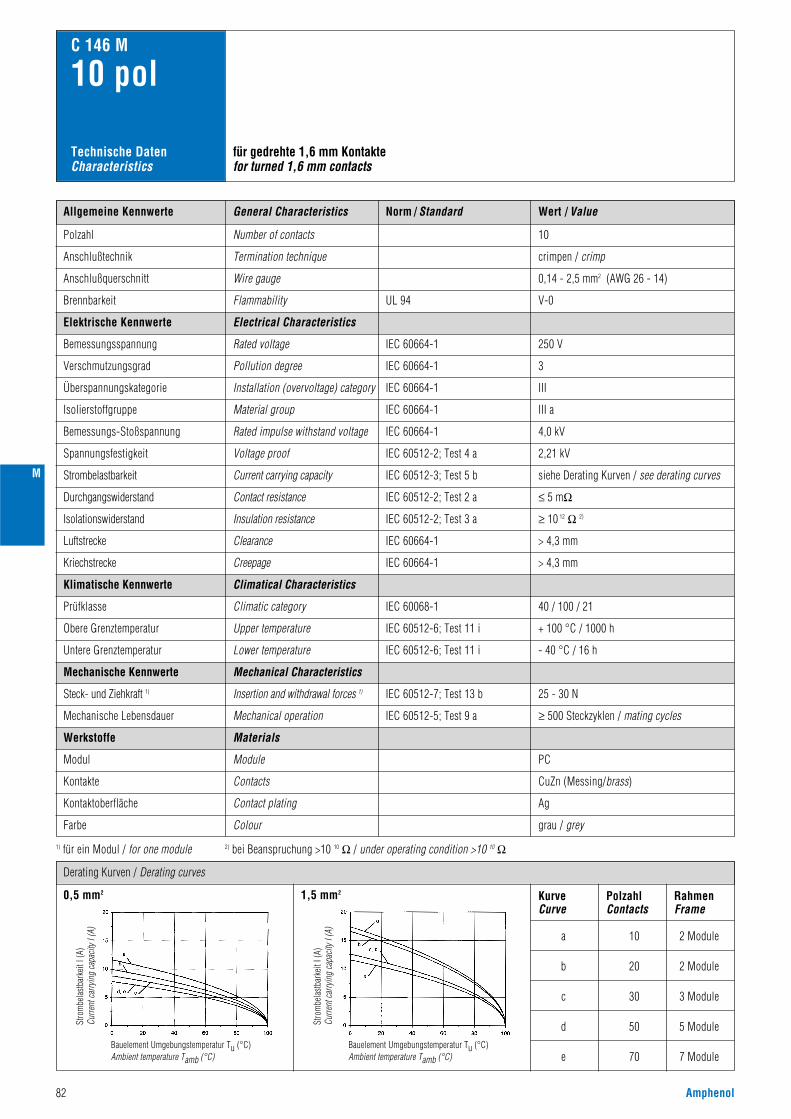
Norm / Standard Wert / ValueAllgemeine Kennwerte
Polzahl
250 V
3
III
III a
4,0 kV
2,21 kV
siehe Derating Kurven / see derating curves
Number of contacts
Anschlußtechnik Termination technique
V-0
crimpen / crimp
Anschlußquerschnitt Wire gauge 0,14 - 2,5 mm2 (AWG 26 - 14)
10
Flammability
Electrical Characteristics
Rated voltage
Pollution degree
C 146 M
10 pol
Installation (overvoltage) category
Material group
Rated impulse withstand voltage
Voltage proof
IEC 60664-1
IEC 60664-1
IEC 60664-1
IEC 60664-1
IEC 60664-1
IEC 60512-2; Test 4 a
UL 94
IEC 60512-3; Test 5 b
IEC 60512-5; Test 9 a
Current carrying capacity
Mechanical operation
Module
≥ 500 Steckzyklen / mating cycles
PC
grau / grey
Elektrische Kennwerte
Bemessungsspannung
Verschmutzungsgrad
Brennbarkeit
Überspannungskategorie
Isolierstoffgruppe
Bemessungs-Stoßspannung
Spannungsfestigkeit
Strombelastbarkeit
≤ 5 mΩIEC 60512-2; Test 2 aContact resistanceDurchgangswiderstand
≥ 10 12 Ω 2)IEC 60512-2; Test 3 aInsulation resistanceIsolationswiderstand
IEC 60068-1
IEC 60512-7; Test 13 b
Climatical Characteristics
Climatic category
Mechanical Characteristics
Insertion and withdrawal forces 1)
40 / 100 / 21
Klimatische Kennwerte
Prüfklasse
IEC 60512-6; Test 11 iUpper temperature
Lower temperature
+ 100 °C / 1000 hObere Grenztemperatur
Untere Grenztemperatur IEC 60512-6; Test 11 i - 40 °C / 16 h
25 - 30 N
Mechanische Kennwerte
Steck- und Ziehkraft 1)
Mechanische Lebensdauer
Werkstoffe
Modul
Contacts CuZn (Messing/brass)Kontakte
Contact plating AgKontaktoberfläche
Farbe Colour
Materials
General Characteristics
1) für ein Modul / for one module 2) bei Beanspruchung >10 10 Ω / under operating condition >10 10 Ω
Technische DatenCharacteristics
> 4,3 mmIEC 60664-1ClearanceLuftstrecke
> 4,3 mmIEC 60664-1CreepageKriechstrecke
für gedrehte 1,6 mm Kontaktefor turned 1,6 mm contacts
Derating Kurven / Derating curves
0,5 mm2 1,5 mm2 KurveCurve
PolzahlContacts
RahmenFrame
a 10 2 Module
2 Module
3 Module
5 Module
7 Module
20
30
50
70
b
c
d
e
82 Amphenol
Stro
mbe
last
bark
eit I
(A)
Curre
nt c
arry
ing
capa
city
I (A
)
Bauelement Umgebungstemperatur Tu (°C)Ambient temperature Tamb (°C)
Stro
mbe
last
bark
eit I
(A)
Curre
nt c
arry
ing
capa
city
I (A
)
Bauelement Umgebungstemperatur Tu (°C)Ambient temperature Tamb (°C)
M
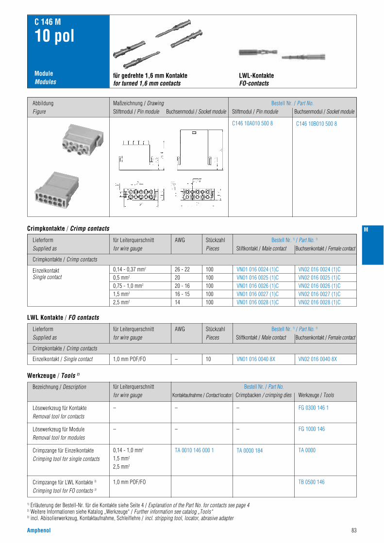
Amphenol 83
M
Crimpkontakte / Crimp contacts
LieferformSupplied as
AWGfür Leiterquerschnittfor wire gauge
StückzahlPieces
Bestell Nr. 1) / Part No. 1)
Stiftkontakt / Male contact Buchsenkontakt / Female contact
ModuleModules
C 146 M
10 pol
0,14 - 0,37 mm2
0,5 mm2
0,75 - 1,0 mm2
1,5 mm2
2,5 mm2
26 - 222020 - 1616 - 1514
100100100100100
VN01 016 0024 (1)CVN01 016 0025 (1)CVN01 016 0026 (1)CVN01 016 0027 (1)CVN01 016 0028 (1)C
VN02 016 0024 (1)CVN02 016 0025 (1)CVN02 016 0026 (1)CVN02 016 0027 (1)CVN02 016 0028 (1)C
EinzelkontaktSingle contact
für gedrehte 1,6 mm Kontaktefor turned 1,6 mm contacts
Bestell Nr. / Part No.Stiftmodul / Pin module Buchsenmodul / Socket module
Crimpkontakte / Crimp contacts
Crimpkontakte / Crimp contacts
LieferformSupplied as
AWGfür Leiterquerschnittfor wire gauge
StückzahlPieces
Bestell Nr. 1) / Part No. 1)
Stiftkontakt / Male contact Buchsenkontakt / Female contact
1,0 mm POF/FO – 10 VN01 016 0040 8X VN02 016 0040 8XEinzelkontakt / Single contact
LWL Kontakte / FO contacts
C146 10A010 500 8 C146 10B010 500 8
für Leiterquerschnittfor wire gauge
Bestell Nr. / Part No.Kontaktaufnahme / Contact locator Crimpbacken / crimping dies Werkzeuge / Tools
–
–
0,14 - 1,0 mm2
1,5 mm2
2,5 mm2
1,0 mm POF/FO
–
–
TA 0010 146 000 1 TA 0000 184
– FG 0300 146 1
FG 1000 146
TA 0000
–
Bezeichnung / Description
Lösewerkzeug für KontakteRemoval tool for contacts
Lösewerkzeug für ModuleRemoval tool for modules
Crimpzange für EinzelkontakteCrimping tool for single contacts
Werkzeuge / Tools 2)
1) Erläuterung der Bestell-Nr. für die Kontakte siehe Seite 4 / Explanation of the Part No. for contacts see page 42) Weitere Informationen siehe Katalog „Werkzeuge“ / Further information see catalog „Tools“3) incl. Abisolierwerkzeug, Kontaktaufnahme, Schleiflehre / incl. stripping tool, locator, abrasive adapter
TB 0500 146Crimpzange für LWL Kontakte 3)
Crimping tool for FO contacts 3)
AbbildungFigure
Maßzeichnung / DrawingStiftmodul / Pin module Buchsenmodul / Socket module
LWL-KontakteFO-contacts
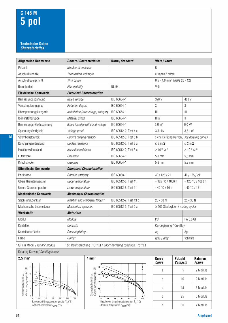
Norm / Standard Wert / ValueAllgemeine Kennwerte
Polzahl
320 V
3
III
III a
6,0 kV
3,51 kV
siehe Derating Kurven / see derating curves
Number of contacts
Anschlußtechnik Termination technique
V-0
crimpen / crimp
Anschlußquerschnitt Wire gauge 0,5 - 4,0 mm2 (AWG 20 - 12)
5
Flammability
Electrical Characteristics
Rated voltage
Pollution degree
C 146 M
5 pol
Installation (overvoltage) category
Material group
Rated impulse withstand voltage
Voltage proof
IEC 60664-1
IEC 60664-1
IEC 60664-1
IEC 60664-1
IEC 60664-1
IEC 60512-2; Test 4 a
UL 94
IEC 60512-3; Test 5 b
IEC 60512-5; Test 9 a
Current carrying capacity
Mechanical operation
Module
≥ 500 Steckzyklen / mating cycles
PC
grau / grey
Elektrische Kennwerte
Bemessungsspannung
Verschmutzungsgrad
Brennbarkeit
Überspannungskategorie
Isolierstoffgruppe
Bemessungs-Stoßspannung
Spannungsfestigkeit
Strombelastbarkeit
≤ 2 mΩIEC 60512-2; Test 2 aContact resistanceDurchgangswiderstand
≥ 10 12 Ω 2)IEC 60512-2; Test 3 aInsulation resistanceIsolationswiderstand
IEC 60068-1
IEC 60512-7; Test 13 b
Climatical Characteristics
Climatic category
Mechanical Characteristics
Insertion and withdrawal forces 1)
40 / 125 / 21
Klimatische Kennwerte
Prüfklasse
IEC 60512-6; Test 11 iUpper temperature
Lower temperature
+ 125 °C / 1000 hObere Grenztemperatur
Untere Grenztemperatur IEC 60512-6; Test 11 i - 40 °C / 16 h
25 - 30 N
Mechanische Kennwerte
Steck- und Ziehkraft 1)
Mechanische Lebensdauer
Werkstoffe
Modul
Contacts Cu-Legierung / Cu-alloyKontakte
Contact plating AgKontaktoberfläche
Farbe Colour
Materials
General Characteristics
1) für ein Modul / for one module 2) bei Beanspruchung >10 10 Ω / under operating condition >10 10 Ω
Technische DatenCharacteristics
5,8 mmIEC 60664-1ClearanceLuftstrecke
5,8 mm
400 V
3
III
II
6,0 kV
3,51 kV
PA 6.6 GF
schwarz
≤ 2 mΩ
≥ 10 12 Ω 2)
40 / 125 / 21
+ 125 °C / 1000 h
- 40 °C / 16 h
25 - 30 N
Ag
5,8 mm
5,8 mmIEC 60664-1CreepageKriechstrecke
Derating Kurven / Derating curves
2,5 mm2 4 mm2 KurveCurve
PolzahlContacts
RahmenFrame
a 5 2 Module
2 Module
3 Module
5 Module
7 Module
10
15
25
35
b
c
d
e
84 Amphenol
Stro
mbe
last
bark
eit I
(A)
Curre
nt c
arry
ing
capa
city
I (A
)
Bauelement Umgebungstemperatur Tu (°C)Ambient temperature Tamb (°C)
Stro
mbe
last
bark
eit I
(A)
Curre
nt c
arry
ing
capa
city
I (A
)
Bauelement Umgebungstemperatur Tu (°C)Ambient temperature Tamb (°C)
M
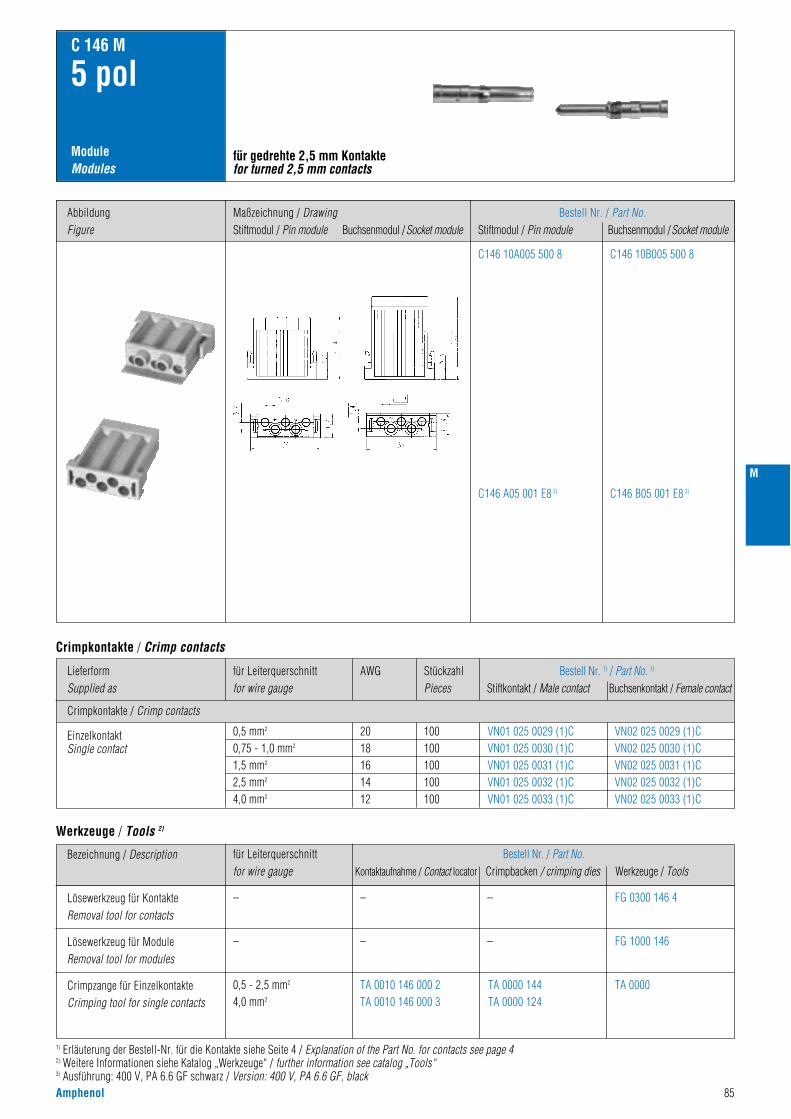
Amphenol 85
M
ModuleModules
C 146 M
5 pol
für gedrehte 2,5 mm Kontaktefor turned 2,5 mm contacts
Bestell Nr. / Part No.Stiftmodul / Pin module Buchsenmodul /Socket module
C146 10A005 500 8
C146 A05 001 E8 3)
C146 10B005 500 8
C146 B05 001 E8 3)
Crimpkontakte / Crimp contacts
LieferformSupplied as
AWGfür Leiterquerschnittfor wire gauge
StückzahlPieces
Bestell Nr. 1) / Part No. 1)
Stiftkontakt / Male contact Buchsenkontakt / Female contact
0,5 mm2
0,75 - 1,0 mm2
1,5 mm2
2,5 mm2
4,0 mm2
2018161412
100100100100100
VN01 025 0029 (1)CVN01 025 0030 (1)CVN01 025 0031 (1)CVN01 025 0032 (1)CVN01 025 0033 (1)C
VN02 025 0029 (1)CVN02 025 0030 (1)CVN02 025 0031 (1)CVN02 025 0032 (1)CVN02 025 0033 (1)C
EinzelkontaktSingle contact
Crimpkontakte / Crimp contacts
für Leiterquerschnittfor wire gauge
Bestell Nr. / Part No.Kontaktaufnahme / Contact locator Crimpbacken / crimping dies Werkzeuge / Tools
–
–
0,5 - 2,5 mm2
4,0 mm2
–
–
TA 0010 146 000 2TA 0010 146 000 3
TA 0000 144TA 0000 124
– FG 0300 146 4
FG 1000 146
TA 0000
–
Bezeichnung / Description
Lösewerkzeug für KontakteRemoval tool for contacts
Lösewerkzeug für ModuleRemoval tool for modules
Crimpzange für EinzelkontakteCrimping tool for single contacts
Werkzeuge / Tools 2)
1) Erläuterung der Bestell-Nr. für die Kontakte siehe Seite 4 / Explanation of the Part No. for contacts see page 42) Weitere Informationen siehe Katalog „Werkzeuge“ / further information see catalog „Tools“3) Ausführung: 400 V, PA 6.6 GF schwarz / Version: 400 V, PA 6.6 GF, black
AbbildungFigure
Maßzeichnung / DrawingStiftmodul / Pin module Buchsenmodul /Socket module

Norm / Standard Wert / ValueAllgemeine Kennwerte
Polzahl
630 V
3
III
III a
8,0 kV
4,26 kV
siehe Derating Kurven / see derating curves
Number of contacts
Anschlußtechnik Termination technique
V-0
crimpen / crimp
Anschlußquerschnitt Wire gauge 1,5 - 10 mm2 (AWG 16 - 8)
3
Flammability
Electrical Characteristics
Rated voltage
Pollution degree
C 146 M
3 pol
Installation (overvoltage) category
Material group
Rated impulse withstand voltage
Voltage proof
IEC 60664-1
IEC 60664-1
IEC 60664-1
IEC 60664-1
IEC 60664-1
IEC 60512-2 Test 4 a
UL 94
IEC 60512-3; Test 5 b
IEC 60068-1
IEC 60512-7; Test 13 b
IEC 60512-5; Test 9 a
Current carrying capacity
Climatical Characteristics
Climatic category
Mechanical Characteristics
Insertion and withdrawal forces 1)
Mechanical operation
Module
40 / 125 / 21
≥ 500 Steckzyklen / mating cycles
PC
grau / grey
Elektrische Kennwerte
Bemessungsspannung
Verschmutzungsgrad
Brennbarkeit
Überspannungskategorie
Isolierstoffgruppe
Bemessungs-Stoßspannung
Spannungsfestigkeit
Strombelastbarkeit
≤ 1 mΩIEC 60512-2; Test 2 aContact resistanceDurchgangswiderstand
≥ 10 12 Ω 2)IEC 60512-2; Test 3 aInsulation resistanceIsolationswiderstand
Klimatische Kennwerte
Prüfklasse
IEC 60512-6; Test 11 iUpper temperature
Lower temperature
+ 125 °C / 1000 hObere Grenztemperatur
Untere Grenztemperatur IEC 60512-6; Test 11 i - 40 °C / 16 h
20 - 30 N
Mechanische Kennwerte
Steck- und Ziehkraft 1)
Mechanische Lebensdauer
Werkstoffe
Modul
Contacts Cu-Legierung / Cu-alloyKontakte
Contact plating AgKontaktoberfläche
Farbe Colour
Materials
General Characteristics
1) für ein Modul / for one module 2) bei Beanspruchung >10 10 Ω / under operating condition >10 10 Ω
Technische DatenCharacteristics
> 12 mmIEC 60664-1ClearanceLuftstrecke
> 12 mmIEC 60664-1CreepageKriechstrecke
Derating Kurven / Derating curves
6 mm2 10 mm2 KurveCurve
PolzahlContacts
RahmenFrame
a 3 2 Module
2 Module
3 Module
5 Module
7 Module
6
9
15
21
b
c
d
e
86 Amphenol
Stro
mbe
last
bark
eit I
(A)
Curre
nt c
arry
ing
capa
city
I (A
)
Bauelement Umgebungstemperatur Tu (°C)Ambient temperature Tamb (°C)
Stro
mbe
last
bark
eit I
(A)
Curre
nt c
arry
ing
capa
city
I (A
)
Bauelement Umgebungstemperatur Tu (°C)Ambient temperature Tamb (°C)
M
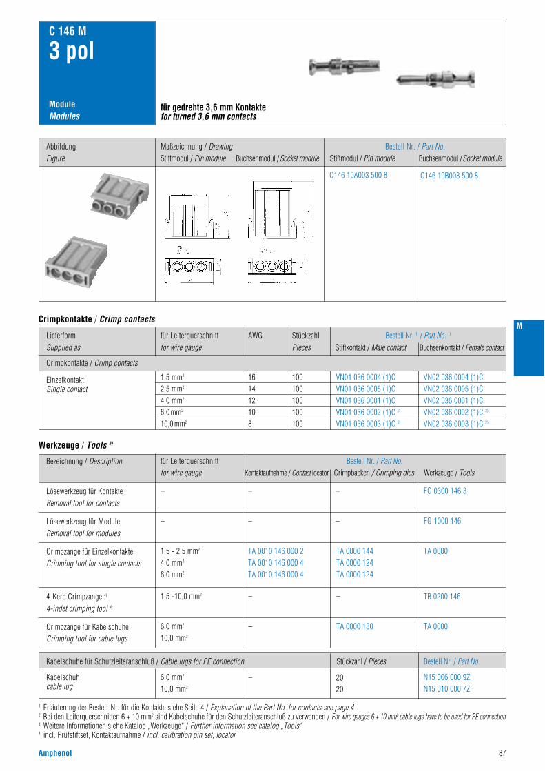
Amphenol 87
M
ModuleModules
C 146 M
3 pol
für gedrehte 3,6 mm Kontaktefor turned 3,6 mm contacts
Bestell Nr. / Part No.Stiftmodul / Pin module Buchsenmodul /Socket module
C146 10A003 500 8 C146 10B003 500 8
Crimpkontakte / Crimp contacts
LieferformSupplied as
AWGfür Leiterquerschnittfor wire gauge
StückzahlPieces
Bestell Nr. 1) / Part No. 1)
Stiftkontakt / Male contact Buchsenkontakt / Female contact
1,5 mm2
2,5 mm2
4,0 mm2
6,0 mm2
10,0 mm2
161412108
100100100100100
VN01 036 0004 (1)CVN01 036 0005 (1)CVN01 036 0001 (1)CVN01 036 0002 (1)C 2)
VN01 036 0003 (1)C 2)
VN02 036 0004 (1)CVN02 036 0005 (1)CVN02 036 0001 (1)CVN02 036 0002 (1)C 2)
VN02 036 0003 (1)C 2)
EinzelkontaktSingle contact
Crimpkontakte / Crimp contacts
Kabelschuhe für Schutzleiteranschluß / Cable lugs for PE connection Bestell Nr. / Part No.Stückzahl / Pieces
6,0 mm2
10,0 mm2
N15 006 000 9ZN15 010 000 7Z
Kabelschuhcable lug
für Leiterquerschnittfor wire gauge
Bestell Nr. / Part No.Kontaktaufnahme / Contact locator Crimpbacken / Crimping dies Werkzeuge / Tools
–
–
1,5 - 2,5 mm2
4,0 mm2
6,0 mm2
1,5 -10,0 mm2
6,0 mm2
10,0 mm2
–
–
– 2020
–
–
–
TA 0010 146 000 2TA 0010 146 000 4TA 0010 146 000 4
TA 0000 144TA 0000 124TA 0000 124
– FG 0300 146 3
FG 1000 146
TA 0000
TB 0200 146
–
Bezeichnung / Description
Lösewerkzeug für KontakteRemoval tool for contacts
Lösewerkzeug für ModuleRemoval tool for modules
Crimpzange für EinzelkontakteCrimping tool for single contacts
Werkzeuge / Tools 3)
1) Erläuterung der Bestell-Nr. für die Kontakte siehe Seite 4 / Explanation of the Part No. for contacts see page 42) Bei den Leiterquerschnitten 6 + 10 mm2 sind Kabelschuhe für den Schutzleiteranschluß zu verwenden / For wire gauges 6 + 10 mm2 cable lugs have to be used for PE connection3) Weitere Informationen siehe Katalog „Werkzeuge“ / Further information see catalog „Tools“4) incl. Prüfstiftset, Kontaktaufnahme / incl. calibration pin set, locator
TA 0000Crimpzange für KabelschuheCrimping tool for cable lugs
4-Kerb Crimpzange 4)
4-indet crimping tool 4)
TA 0000 180
AbbildungFigure
Maßzeichnung / DrawingStiftmodul / Pin module Buchsenmodul /Socket module
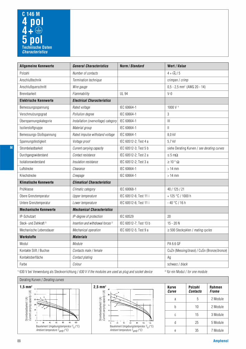
Norm / Standard Wert / ValueAllgemeine Kennwerte
Polzahl
1000 V 1)
3
III
II
8,0 kV
5,7 kV
siehe Derating Kurven / see derating curves
Number of contacts
Anschlußtechnik Termination technique
V-0
crimpen / crimp
Anschlußquerschnitt Wire gauge 0,5 - 2,5 mm2 (AWG 20 - 14)
4 + / 5
Flammability
Electrical Characteristics
Rated voltage
Pollution degree
C 146 M
4 pol4+ 5 pol
Installation (overvoltage) category
Material group
Rated impulse withstand voltage
Voltage proof
IEC 60664-1
IEC 60664-1
IEC 60664-1
IEC 60664-1
IEC 60664-1
IEC 60512-2; Test 4 a
UL 94
IEC 60512-3; Test 5 bCurrent carrying capacity
Elektrische Kennwerte
Bemessungsspannung
Verschmutzungsgrad
Brennbarkeit
Überspannungskategorie
Isolierstoffgruppe
Bemessungs-Stoßspannung
Spannungsfestigkeit
Strombelastbarkeit
≤ 5 mΩIEC 60512-2; Test 2 aContact resistanceDurchgangswiderstand
≥ 10 12 ΩIEC 60512-2; Test 3 aInsulation resistanceIsolationswiderstand
IEC 60068-1
Climatical Characteristics
Climatic category
Mechanical Characteristics
40 / 125 / 21
Klimatische Kennwerte
Prüfklasse
IEC 60512-6; Test 11 iUpper temperature
Lower temperature
+ 125 °C / 1000 hObere Grenztemperatur
Untere Grenztemperatur IEC 60512-6; Test 11 i - 40 °C / 16 h
Mechanische Kennwerte
General Characteristics
Technische DatenCharacteristics
IEC 60512-5; Test 9 aMechanical operation
Module
≥ 500 Steckzyklen / mating cycles
PA 6.6 GF
schwarz / black
IEC 60512-7; Test 13 bInsertion and withdrawal forces 2)Steck- und Ziehkraft 2)
Mechanische Lebensdauer
IEC 60529IP-degree of protection 20
15 - 20 N
IP-Schutzart
Werkstoffe
Modul
Contacts male / female CuZn (Messing/brass) / CuSn (Bronze/bronce)Kontakte Stift / Buchse
Contact plating AgKontaktoberfläche
Farbe Colour
Materials
1) 630 V bei Verwendung als Steckvorrichtung / 630 V if the modules are used as plug and socket device 2) für ein Modul / for one module
Derating Kurven / Derating curves
> 14 mmIEC 60664-1ClearanceLuftstrecke
> 14 mmIEC 60664-1CreepageKriechstrecke
1,5 mm2 2,5 mm2 KurveCurve
PolzahlContacts
RahmenFrame
a 5 2 Module
b 10 2 Module
c 15 3 Module
d 25 5 Module
e 35 7 Module
88 Amphenol
Stro
mbe
last
bark
eit I
(A)
Curre
nt c
arry
ing
capa
city
I (A
)
Bauelement Umgebungstemperatur Tu (°C)Ambient temperature Tamb (°C)
Stro
mbe
last
bark
eit I
(A)
Curre
nt c
arry
ing
capa
city
I (A
)
Bauelement Umgebungstemperatur Tu (°C)Ambient temperature Tamb (°C)
M
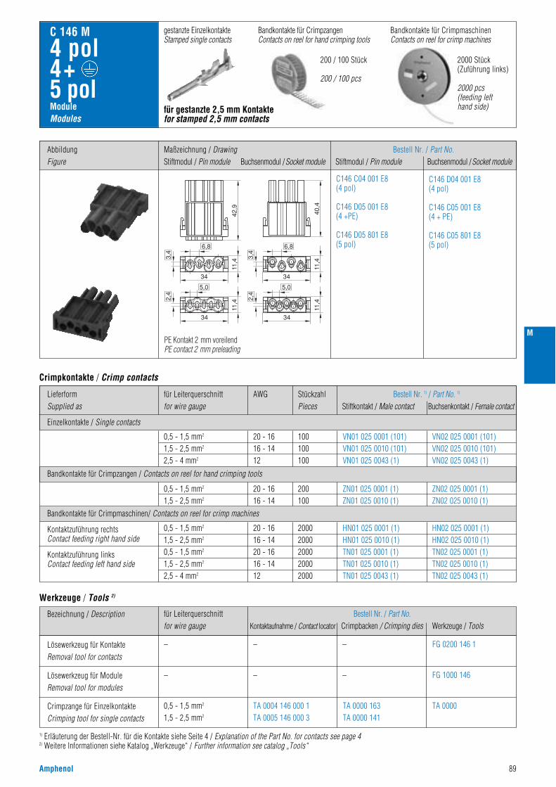
Amphenol 89
M
ModuleModules
C 146 M
4 pol4+ 5 pol
Bandkontakte für CrimpmaschinenContacts on reel for crimp machines
200 / 100 Stück
200 / 100 pcs
2000 Stück(Zuführung links)
2000 pcs(feeding lefthand side)
Bandkontakte für CrimpzangenContacts on reel for hand crimping tools
gestanzte EinzelkontakteStamped single contacts
für gestanzte 2,5 mm Kontaktefor stamped 2,5 mm contacts
Bestell Nr. / Part No.Stiftmodul / Pin module Buchsenmodul /Socket module
Einzelkontakte / Single contacts
Bandkontakte für Crimpzangen / Contacts on reel for hand crimping tools
Bandkontakte für Crimpmaschinen/ Contacts on reel for crimp machines
LieferformSupplied as
AWGfür Leiterquerschnittfor wire gauge
StückzahlPieces
Bestell Nr. 1) / Part No. 1)
Stiftkontakt / Male contact Buchsenkontakt / Female contact
0,5 - 1,5 mm2
1,5 - 2,5 mm2
0,5 - 1,5 mm2
1,5 - 2,5 mm2
2,5 - 4 mm2
0,5 - 1,5 mm2
1,5 - 2,5 mm2
0,5 - 1,5 mm2
1,5 - 2,5 mm2
2,5 - 4 mm2
20 - 1616 - 1420 - 1616 - 1412
20 - 1616 - 14
20 - 1616 - 1412
20002000200020002000
200100
100100100
HN01 025 0001 (1)HN01 025 0010 (1)TN01 025 0001 (1)TN01 025 0010 (1)TN01 025 0043 (1)
ZN01 025 0001 (1)ZN01 025 0010 (1)
VN01 025 0001 (101)VN01 025 0010 (101)VN01 025 0043 (1)
HN02 025 0001 (1)HN02 025 0010 (1)TN02 025 0001 (1)TN02 025 0010 (1)TN02 025 0043 (1)
ZN02 025 0001 (1)ZN02 025 0010 (1)
VN02 025 0001 (101)VN02 025 0010 (101)VN02 025 0043 (1)
Kontaktzuführung rechtsContact feeding right hand side
Kontaktzuführung linksContact feeding left hand side
Crimpkontakte / Crimp contacts
C146 C04 001 E8(4 pol)
C146 D05 001 E8(4 +PE)
C146 D05 801 E8(5 pol)
C146 D04 001 E8(4 pol)
C146 C05 001 E8(4 + PE)
C146 C05 801 E8(5 pol)
für Leiterquerschnittfor wire gauge
Bestell Nr. / Part No.Kontaktaufnahme / Contact locator Crimpbacken / Crimping dies Werkzeuge / Tools
–
–
0,5 - 1,5 mm2
1,5 - 2,5 mm2
–
–
TA 0004 146 000 1TA 0005 146 000 3
TA 0000 163TA 0000 141
– FG 0200 146 1
FG 1000 146
TA 0000
–
Bezeichnung / Description
Lösewerkzeug für KontakteRemoval tool for contacts
Lösewerkzeug für ModuleRemoval tool for modules
Crimpzange für EinzelkontakteCrimping tool for single contacts
Werkzeuge / Tools 2)
1) Erläuterung der Bestell-Nr. für die Kontakte siehe Seite 4 / Explanation of the Part No. for contacts see page 42) Weitere Informationen siehe Katalog „Werkzeuge“ / Further information see catalog „Tools“
AbbildungFigure
Maßzeichnung / DrawingStiftmodul / Pin module Buchsenmodul /Socket module
42,9
40,4
11,4
3,4
6,8
34
11,42,
4
5,0
34
11,4
3,4
6,8
34
11,42,
4
5,0
34
PE Kontakt 2 mm voreilendPE contact 2 mm preleading
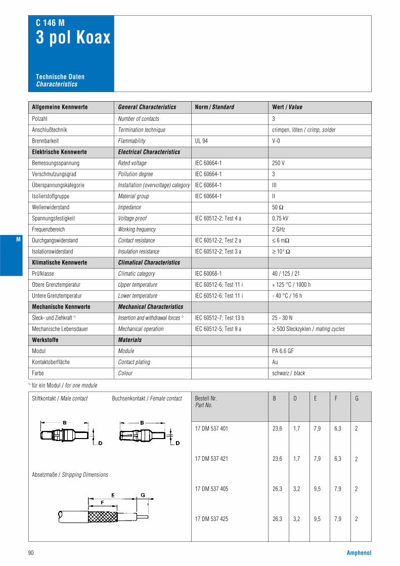
Norm / Standard Wert / ValueAllgemeine Kennwerte
Polzahl Number of contacts
Anschlußtechnik Termination technique crimpen, löten / crimp, solder
3
C 146 M
3 pol Koax
IEC 60512-5; Test 9 aMechanical operation
Module
≥ 500 Steckzyklen / mating cycles
25 - 30 N
PA 6.6 GF
250 V
3
III
II
50 Ω
0,75 kV
2 GHz
V-0Flammability
Electrical Characteristics
Rated voltage
Pollution degree
Installation (overvoltage) category
Material group
Impedance
Voltage proof
IEC 60664-1
IEC 60664-1
IEC 60664-1
IEC 60664-1
IEC 60512-2; Test 4 a
UL 94
Working frequency
Elektrische Kennwerte
Bemessungsspannung
Verschmutzungsgrad
Brennbarkeit
Überspannungskategorie
Isolierstoffgruppe
Wellenwiderstand
Spannungsfestigkeit
Frequenzbereich
IEC 60068-1
IEC 60512-7; Test 13 b
Climatical Characteristics
Climatic category
Mechanical Characteristics
Insertion and withdrawal forces 1)
40 / 125 / 21
≤ 6 mΩIEC 60512-2; Test 2 aContact resistanceDurchgangswiderstand
≥ 10 6 ΩIEC 60512-2; Test 3 aInsulation resistanceIsolationswiderstand
Klimatische Kennwerte
Prüfklasse
IEC 60512-6; Test 11 iUpper temperature
Lower temperature
+ 125 °C / 1000 hObere Grenztemperatur
Untere Grenztemperatur IEC 60512-6; Test 11 i - 40 °C / 16 h
Mechanische Kennwerte
Steck- und Ziehkraft 1)
Mechanische Lebensdauer
Werkstoffe
Modul
Contact plating Au
schwarz / black
Kontaktoberfläche
Farbe Colour
Materials
General Characteristics
1) für ein Modul / for one module
Technische DatenCharacteristics
Bestell Nr.Part No.
Stiftkontakt / Male contact
Absetzmaße / Stripping Dimensions
Buchsenkontakt / Female contact
17 DM 537 401
17 DM 537 421
17 DM 537 405
17 DM 537 425
23,6
23,6
26,3
26,3
1,7
1,7
3,2
3,2
7,9
7,9
9,5
9,5
6,3
6,3
7,9
7,9
2
2
2
2
B D E F G
90 Amphenol
M
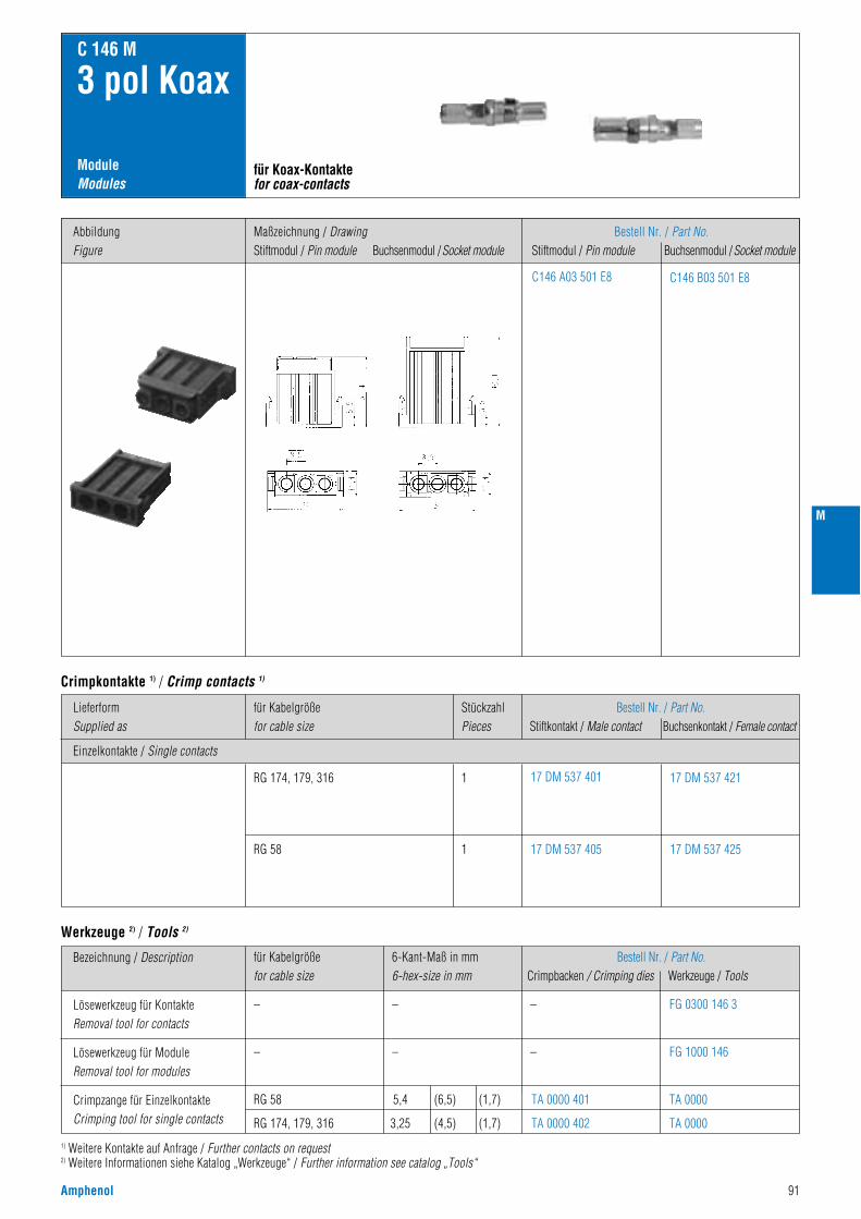
Amphenol 91
M
ModuleModules
C 146 M
3 pol Koax
für Koax-Kontaktefor coax-contacts
Bestell Nr. / Part No.Stiftmodul / Pin module Buchsenmodul /Socket module
Einzelkontakte / Single contacts
LieferformSupplied as
für Kabelgrößefor cable size
StückzahlPieces
Bestell Nr. / Part No.Stiftkontakt / Male contact Buchsenkontakt / Female contact
RG 174, 179, 316
RG 58
1
1
17 DM 537 401
17 DM 537 405
17 DM 537 421
17 DM 537 425
Crimpkontakte 1) / Crimp contacts 1)
C146 A03 501 E8 C146 B03 501 E8
für Kabelgrößefor cable size
6-Kant-Maß in mm6-hex-size in mm
Bestell Nr. / Part No.Crimpbacken / Crimping dies Werkzeuge / Tools
–
–
RG 58
RG 174, 179, 316
–
–
5,4 (6,5) (1,7)
3,25 (4,5) (1,7)
TA 0000 401
TA 0000 402
– FG 0300 146 3
FG 1000 146
TA 0000
TA 0000
–
Bezeichnung / Description
Lösewerkzeug für KontakteRemoval tool for contacts
Lösewerkzeug für ModuleRemoval tool for modules
Crimpzange für EinzelkontakteCrimping tool for single contacts
Werkzeuge 2) / Tools 2)
1) Weitere Kontakte auf Anfrage / Further contacts on request2) Weitere Informationen siehe Katalog „Werkzeuge“ / Further information see catalog „Tools“
AbbildungFigure
Maßzeichnung / DrawingStiftmodul / Pin module Buchsenmodul /Socket module

Norm / Standard Wert / ValueAllgemeine Kennwerte
Polzahl
1000 V 1)
3
III
II
8,0 kV
5,7 kV
siehe Derating Kurven / see derating curves
Number of contacts
Anschlußtechnik Termination technique
V-0
crimpen / crimp
Anschlußquerschnitt Wire gauge 1,5 - 10 mm2 (AWG 16 - 8)
3
Flammability
Electrical Characteristics
Rated voltage
Pollution degree
C 146 M
3 pol
Installation (overvoltage) category
Material group
Rated impulse withstand voltage
Voltage proof
IEC 60664-1
IEC 60664-1
IEC 60664-1
IEC 60664-1
IEC 60664-1
IEC 60512-2; Test 4 a
UL 94
IEC 60512-3; Test 5 bCurrent carrying capacity
Elektrische Kennwerte
Bemessungsspannung
Verschmutzungsgrad
Brennbarkeit
Überspannungskategorie
Isolierstoffgruppe
Bemessungs-Stoßspannung
Spannungsfestigkeit
Strombelastbarkeit
≤ 1 mΩIEC 60512-2; Test 2 aContact resistanceDurchgangswiderstand
≥ 10 12 ΩIEC 60512-2; Test 3 aInsulation resistanceIsolationswiderstand
IEC 60068-1
Climatical Characteristics
Climatic category
Mechanical Characteristics
40 / 125 / 21
Klimatische Kennwerte
Prüfklasse
IEC 60512-6; Test 11 iUpper temperature
Lower temperature
+ 125 °C / 1000 hObere Grenztemperatur
Untere Grenztemperatur IEC 60512-6; Test 11 i - 40 °C / 16 h
Mechanische Kennwerte
General Characteristics
Technische DatenCharacteristics
IEC 60512-5; Test 9 aMechanical operation
Module
≥ 500 Steckzyklen / mating cycles
PA 6.6 GF
schwarz / black
IEC 60512-7; Test 13 bInsertion and withdrawal forces 2)Steck- und Ziehkraft 2)
Mechanische Lebensdauer
IEC 60529IP-degree of protection 20
20 - 30 N
IP-Schutzart
Werkstoffe
Modul
Contacts Cu-Legierung / Cu-alloyKontakte
Contact plating AgKontaktoberfläche
Farbe Colour
Materials
1) 630 V bei Verwendung als Steckvorrichtung / 630 V if the modules are used as plug and socket device 2) für ein Modul / for one module
Derating Kurven / Derating curves
> 14 mmIEC 60664-1ClearanceLuftstrecke
> 14 mmIEC 60664-1CreepageKriechstrecke
6 mm2 10 mm2 KurveCurve
PolzahlContacts
RahmenFrame
a 3 2 Module
b 6 2 Module
c 9 3 Module
d 15 5 Module
e 21 7 Module
92 Amphenol
Stro
mbe
last
bark
eit I
(A)
Curre
nt c
arry
ing
capa
city
I (A
)
Bauelement Umgebungstemperatur Tu (°C)Ambient temperature Tamb (°C)
Stro
mbe
last
bark
eit I
(A)
Curre
nt c
arry
ing
capa
city
I (A
)
Bauelement Umgebungstemperatur Tu (°C)Ambient temperature Tamb (°C)
M
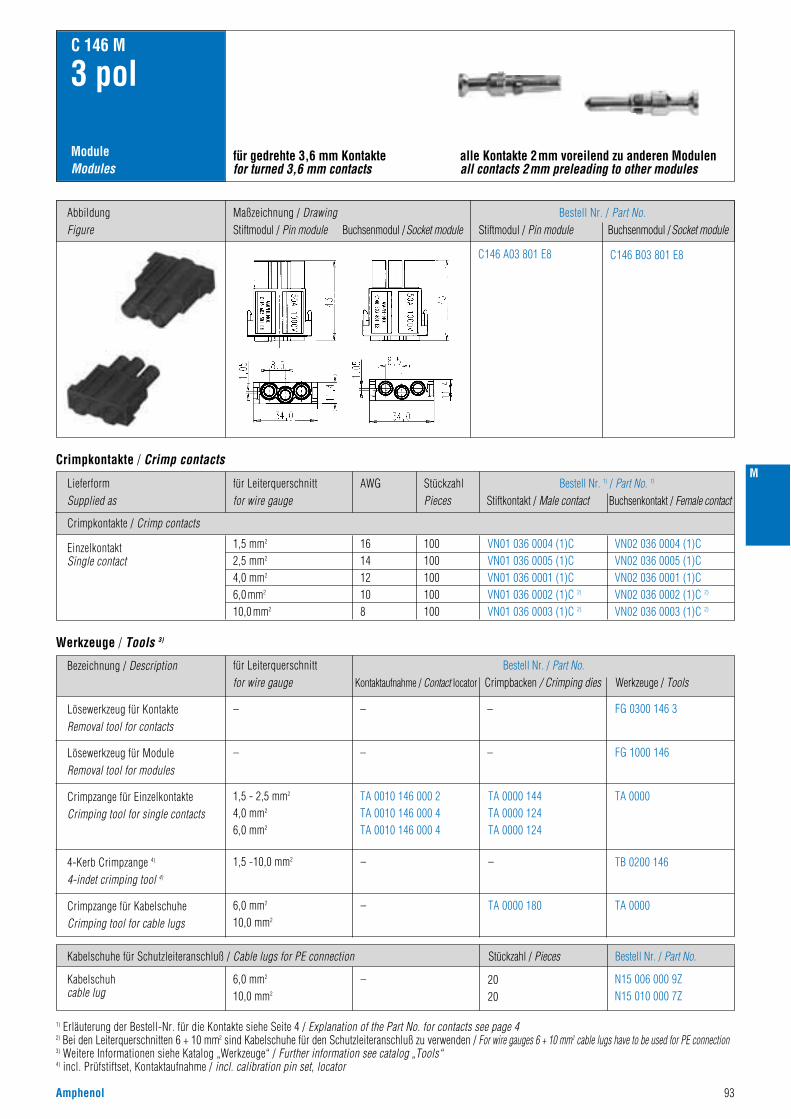
Amphenol 93
M
ModuleModules
C 146 M
3 pol
für gedrehte 3,6 mm Kontaktefor turned 3,6 mm contacts
alle Kontakte 2mm voreilend zu anderen Modulenall contacts 2mm preleading to other modules
Bestell Nr. / Part No.Stiftmodul / Pin module Buchsenmodul /Socket module
C146 A03 801 E8 C146 B03 801 E8
Crimpkontakte / Crimp contacts
LieferformSupplied as
AWGfür Leiterquerschnittfor wire gauge
StückzahlPieces
Bestell Nr. 1) / Part No. 1)
Stiftkontakt / Male contact Buchsenkontakt / Female contact
1,5 mm2
2,5 mm2
4,0 mm2
6,0 mm2
10,0 mm2
161412108
100100100100100
VN01 036 0004 (1)CVN01 036 0005 (1)CVN01 036 0001 (1)CVN01 036 0002 (1)C 2)
VN01 036 0003 (1)C 2)
VN02 036 0004 (1)CVN02 036 0005 (1)CVN02 036 0001 (1)CVN02 036 0002 (1)C 2)
VN02 036 0003 (1)C 2)
EinzelkontaktSingle contact
Crimpkontakte / Crimp contacts
Kabelschuhe für Schutzleiteranschluß / Cable lugs for PE connection Bestell Nr. / Part No.Stückzahl / Pieces
6,0 mm2
10,0 mm2
N15 006 000 9ZN15 010 000 7Z
Kabelschuhcable lug
für Leiterquerschnittfor wire gauge
Bestell Nr. / Part No.Kontaktaufnahme / Contact locator Crimpbacken / Crimping dies Werkzeuge / Tools
–
–
1,5 - 2,5 mm2
4,0 mm2
6,0 mm2
1,5 -10,0 mm2
6,0 mm2
10,0 mm2
–
–
– 2020
–
–
–
TA 0010 146 000 2TA 0010 146 000 4TA 0010 146 000 4
TA 0000 144TA 0000 124TA 0000 124
– FG 0300 146 3
FG 1000 146
TA 0000
TB 0200 146
–
Bezeichnung / Description
Lösewerkzeug für KontakteRemoval tool for contacts
Lösewerkzeug für ModuleRemoval tool for modules
Crimpzange für EinzelkontakteCrimping tool for single contacts
Werkzeuge / Tools 3)
1) Erläuterung der Bestell-Nr. für die Kontakte siehe Seite 4 / Explanation of the Part No. for contacts see page 42) Bei den Leiterquerschnitten 6 + 10 mm2 sind Kabelschuhe für den Schutzleiteranschluß zu verwenden / For wire gauges 6 + 10 mm2 cable lugs have to be used for PE connection3) Weitere Informationen siehe Katalog „Werkzeuge“ / Further information see catalog „Tools“4) incl. Prüfstiftset, Kontaktaufnahme / incl. calibration pin set, locator
TA 0000Crimpzange für KabelschuheCrimping tool for cable lugs
4-Kerb Crimpzange 4)
4-indet crimping tool 4)
TA 0000 180
AbbildungFigure
Maßzeichnung / DrawingStiftmodul / Pin module Buchsenmodul /Socket module
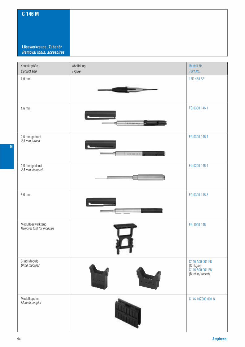
94 Amphenol
M
Lösewerkzeuge, ZubehörRemoval tools, accesoires
C 146 M
KontaktgrößeContact size
1,0 mm
AbbildungFigure
Bestell Nr.Part No.
1,6 mm
2,5 mm gedreht2,5 mm turned
2,5 mm gestanzt2,5 mm stamped
3,6 mm
ModullösewerkzeugRemoval tool for modules
FG 0300 146 4
FG 0200 146 1
FG 0300 146 3
FG 0300 146 1
17D 438 SP
FG 1000 146
ModulkopplerModule coupler
C146 10Z000 001 8
Blind ModuleBlind modules
C146 A00 001 E8(Stift/pin)C146 B00 001 E8(Buchse/socket)
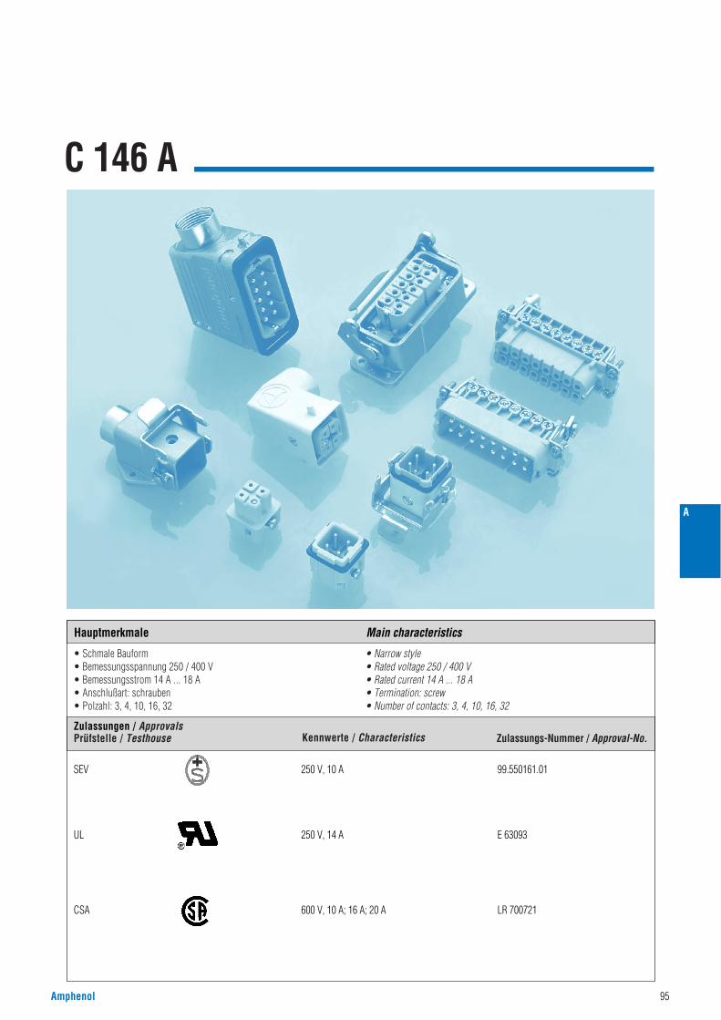
C 146 A
• Schmale Bauform• Bemessungsspannung 250 / 400 V• Bemessungsstrom 14 A ... 18 A• Anschlußart: schrauben• Polzahl: 3, 4, 10, 16, 32
• Narrow style• Rated voltage 250 / 400 V• Rated current 14 A ... 18 A• Termination: screw• Number of contacts: 3, 4, 10, 16, 32
Amphenol 95
A
Zulassungen / ApprovalsPrüfstelle / Testhouse Kennwerte / Characteristics Zulassungs-Nummer / Approval-No.
Hauptmerkmale Main characteristics
SEV 250 V, 10 A 99.550161.01
UL 250 V, 14 A E 63093
CSA 600 V, 10 A; 16 A; 20 A LR 700721
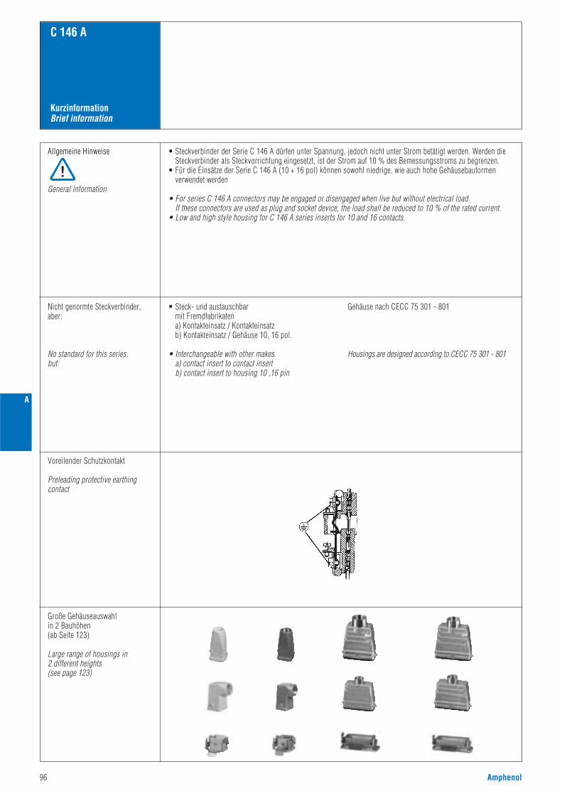
96 Amphenol
KurzinformationBrief information
C 146 A
Allgemeine Hinweise
General information
• Steckverbinder der Serie C 146 A dürfen unter Spannung, jedoch nicht unter Strom betätigt werden. Werden dieSteckverbinder als Steckvorrichtung eingesetzt, ist der Strom auf 10 % des Bemessungsstroms zu begrenzen.
• Für die Einsätze der Serie C 146 A (10 + 16 pol) können sowohl niedrige, wie auch hohe Gehäusebauformenverwendet werden
• For series C 146 A connectors may be engaged or disengaged when live but without electrical load. If these connectors are used as plug and socket device, the load shall be reduced to 10 % of the rated current.
• Low and high style housing for C 146 A series inserts for 10 and 16 contacts.
Nicht genormte Steckverbinder,aber:
No standard for this series,but:
• Steck- und austauschbarmit Fremdfabrikatena) Kontakteinsatz / Kontakteinsatzb) Kontakteinsatz / Gehäuse 10, 16 pol.
• Interchangeable with other makesa) contact insert to contact insertb) contact insert to housing 10 ,16 pin
Gehäuse nach CECC 75 301 - 801
Housings are designed according to CECC 75 301 - 801
Voreilender Schutzkontakt
Preleading protective earthing contact
Große Gehäuseauswahlin 2 Bauhöhen(ab Seite 123)
Large range of housings in2 different heights(see page 123)
A
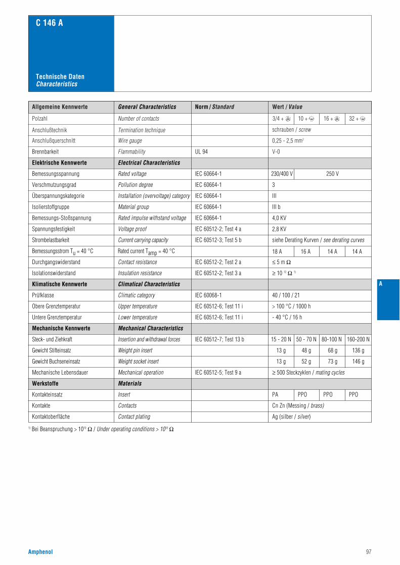
Amphenol 97
Norm / Standard Wert / ValueAllgemeine Kennwerte
Polzahl Number of contacts
Anschlußtechnik Termination technique
V-0
schrauben / screw
Anschlußquerschnitt Wire gauge 0,25 - 2,5 mm2
3/4 + 10 + 16 + 32 +
Flammability
C 146 A
UL 94Brennbarkeit
General Characteristics
Technische DatenCharacteristics
230/400 V 250 V
3
III
III b
4,0 KV
2,8 KV
siehe Derating Kurven / see derating curves
Electrical Characteristics
Rated voltage
Pollution degree
Installation (overvoltage) category
Material group
Rated impulse withstand voltage
Voltage proof
IEC 60664-1
IEC 60664-1
IEC 60664-1
IEC 60664-1
IEC 60664-1
IEC 60512-2; Test 4 a
IEC 60512-3; Test 5 bCurrent carrying capacity
Elektrische Kennwerte
Bemessungsspannung
Verschmutzungsgrad
Überspannungskategorie
Isolierstoffgruppe
Bemessungs-Stoßspannung
Spannungsfestigkeit
Strombelastbarkeit
Rated current Tamp = 40 °CBemessungsstrom Tu = 40 °C
≤ 5 m ΩIEC 60512-2; Test 2 a
IEC 60068-1
Contact resistance
Climatical Characteristics
Climatic category 40 / 100 / 21
Durchgangswiderstand
≥ 10 12 Ω 1)IEC 60512-2; Test 3 aInsulation resistanceIsolationswiderstand
Klimatische Kennwerte
Prüfklasse
Insert
Contacts
Contact plating
PA PPO PPO PPO
Cn Zn (Messing / brass)
Ag (silber / silver)
IEC 60512-7; Test 13 b
IEC 60512-5; Test 9 a
Mechanical Characteristics
Insertion and withdrawal forces
Weight pin insert
Weight socket insert
Mechanical operation ≥ 500 Steckzyklen / mating cycles
Mechanische Kennwerte
Steck- und Ziehkraft
Gewicht Stifteinsatz
Gewicht Buchseneinsatz
Mechanische Lebensdauer
Werkstoffe
Kontakteinsatz
Kontakte
Kontaktoberfläche
1) Bei Beanspruchung > 1010 Ω / Under operating conditions > 1010 Ω
Materials
IEC 60512-6; Test 11 iUpper temperature
Lower temperature
> 100 °C / 1000 hObere Grenztemperatur
Untere Grenztemperatur IEC 60512-6; Test 11 i - 40 °C / 16 h
18 A 16 A 14 A 14 A
A
13 g
15 - 20 N
13 g
48 g
50 - 70 N
52 g
68 g
80-100 N
73 g
136 g
160-200 N
146 g
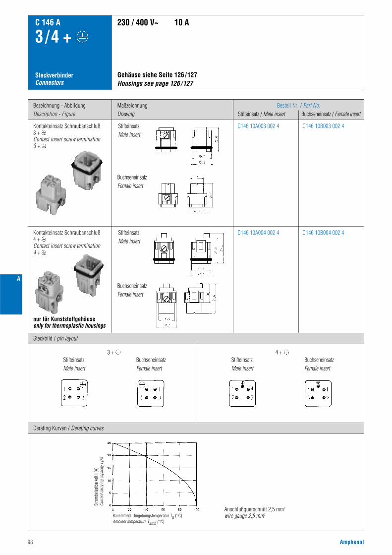
98 Amphenol
A
Bezeichnung - AbbildungDescription - Figure
MaßzeichnungDrawing
Bestell Nr. / Part No.Stifteinsatz / Male insert Buchseneinsatz / Female insert
C 146 A
3 /4 +
SteckverbinderConnectors
Gehäuse siehe Seite 126/127 Housings see page 126/127
230 / 400 V~ 10 A
Derating Kurven / Derating curves
Kontakteinsatz Schraubanschluß3 +Contact insert screw termination3 +
C146 10A003 002 4 C146 10B003 002 4
Steckbild / pin layout
nur für Kunststoffgehäuseonly for thermoplastic housings
C146 10A004 002 4 C146 10B004 002 4Kontakteinsatz Schraubanschluß4 +Contact insert screw termination4 +
Anschlußquerschnitt 2,5 mm2
wire gauge 2,5 mm2
Stro
mbe
last
bark
eit I
(A)
Curre
nt c
arry
ing
capa
city
I (A
)
Bauelement Umgebungstemperatur Tu (°C)Ambient temperature Tamb (°C)
BuchseneinsatzFemale insert
StifteinsatzMale insert
StifteinsatzMale insert
BuchseneinsatzFemale insert
3 + 4 +StifteinsatzMale insert
BuchseneinsatzFemale insert
StifteinsatzMale insert
BuchseneinsatzFemale insert
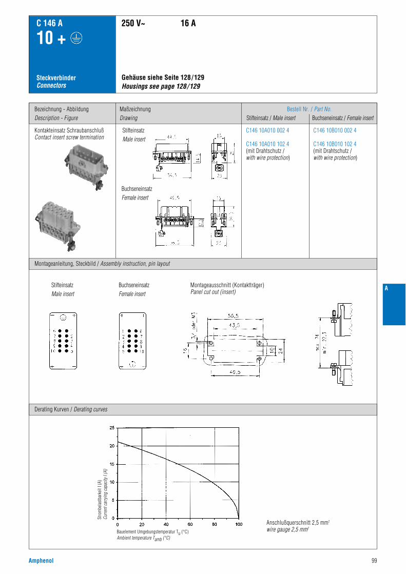
Amphenol 99
A
Bezeichnung - AbbildungDescription - Figure
MaßzeichnungDrawing
Bestell Nr. / Part No.Stifteinsatz / Male insert Buchseneinsatz / Female insert
C 146 A
10 +
SteckverbinderConnectors
Gehäuse siehe Seite 128/129 Housings see page 128/129
250 V~ 16 A
Derating Kurven / Derating curves
Kontakteinsatz SchraubanschlußContact insert screw termination
C146 10A010 002 4
C146 10A010 102 4(mit Drahtschutz /with wire protection)
C146 10B010 002 4
C146 10B010 102 4(mit Drahtschutz /with wire protection)
Montageanleitung, Steckbild / Assembly instruction, pin layout
Anschlußquerschnitt 2,5 mm2
wire gauge 2,5 mm2
StifteinsatzMale insert
BuchseneinsatzFemale insert
Montageausschnitt (Kontaktträger)Panel cut out (insert)
StifteinsatzMale insert
BuchseneinsatzFemale insert
Stro
mbe
last
bark
eit I
(A)
Curre
nt c
arry
ing
capa
city
I (A
)
Bauelement Umgebungstemperatur Tu (°C)Ambient temperature Tamb (°C)
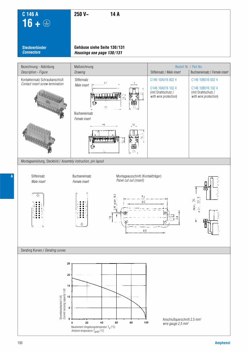
100 Amphenol
A
Bezeichnung - AbbildungDescription - Figure
MaßzeichnungDrawing
Bestell Nr. / Part No.Stifteinsatz / Male insert Buchseneinsatz / Female insert
C 146 A
16 +
SteckverbinderConnectors
Gehäuse siehe Seite 130/131 Housings see page 130/131
250 V~ 14 A
Derating Kurven / Derating curves
Kontakteinsatz SchraubanschlußContact insert screw termination
C146 10A016 002 4
C146 10A016 102 4(mit Drahtschutz /with wire protection)
C146 10B016 002 4
C146 10B016 102 4(mit Drahtschutz /with wire protection)
Montageanleitung, Steckbild / Assembly instruction, pin layout
Anschlußquerschnitt 2,5 mm2
wire gauge 2,5 mm2
StifteinsatzMale insert
BuchseneinsatzFemale insert
Montageausschnitt (Kontaktträger)Panel cut out (insert)
StifteinsatzMale insert
BuchseneinsatzFemale insert
Stro
mbe
last
bark
eit I
(A)
Curre
nt c
arry
ing
capa
city
I (A
)
Bauelement Umgebungstemperatur Tu (°C)Ambient temperature Tamb (°C)
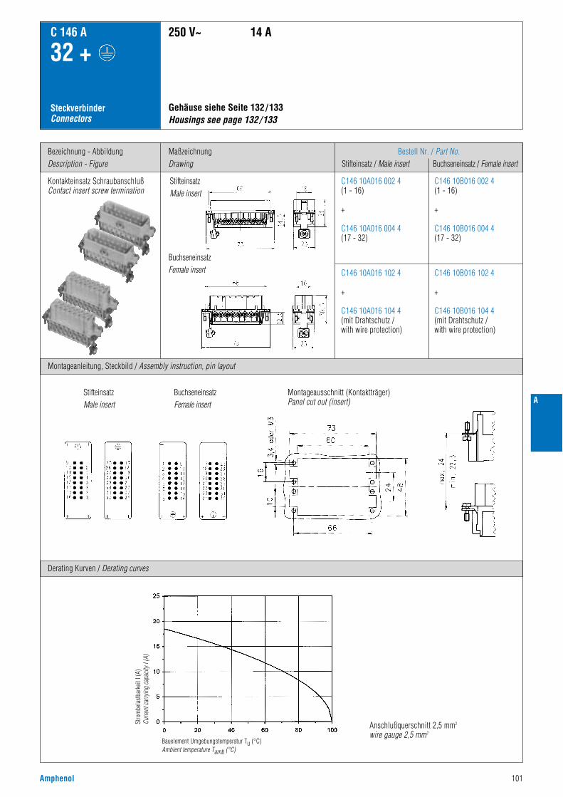
Amphenol 101
A
Bezeichnung - AbbildungDescription - Figure
MaßzeichnungDrawing
Bestell Nr. / Part No.Stifteinsatz / Male insert Buchseneinsatz / Female insert
C 146 A
32 +
SteckverbinderConnectors
Gehäuse siehe Seite 132/133Housings see page 132/133
250 V~ 14 A
Derating Kurven / Derating curves
Kontakteinsatz SchraubanschlußContact insert screw termination
C146 10A016 002 4(1 - 16)
+
C146 10A016 004 4(17 - 32)
C146 10B016 002 4(1 - 16)
+
C146 10B016 004 4(17 - 32)
C146 10A016 102 4
+
C146 10A016 104 4(mit Drahtschutz / with wire protection)
C146 10B016 102 4
+
C146 10B016 104 4(mit Drahtschutz / with wire protection)
Montageanleitung, Steckbild / Assembly instruction, pin layout
Anschlußquerschnitt 2,5 mm2
wire gauge 2,5 mm2
StifteinsatzMale insert
BuchseneinsatzFemale insert
Montageausschnitt (Kontaktträger)Panel cut out (insert)
StifteinsatzMale insert
BuchseneinsatzFemale insert
Stro
mbe
last
bark
eit I
(A)
Curre
nt c
arry
ing
capa
city
I (A
)
Bauelement Umgebungstemperatur Tu (°C)Ambient temperature Tamb (°C)

102 Amphenol
A
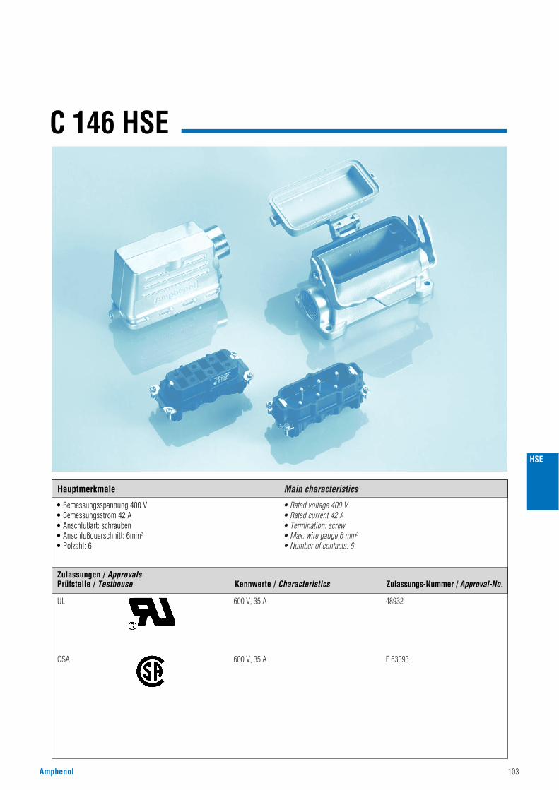
Amphenol 103
C 146 HSE
• Bemessungsspannung 400 V• Bemessungsstrom 42 A• Anschlußart: schrauben• Anschlußquerschnitt: 6mm2
• Polzahl: 6
• Rated voltage 400 V• Rated current 42 A• Termination: screw• Max. wire gauge 6 mm2
• Number of contacts: 6
HSE
Hauptmerkmale Main characteristics
UL 600 V, 35 A 48932
CSA 600 V, 35 A E 63093
Zulassungen / ApprovalsPrüfstelle / Testhouse Kennwerte / Characteristics Zulassungs-Nummer / Approval-No.
104 Amphenol
Norm / Standard Wert / ValueAllgemeine Kennwerte
Polzahl Number of contacts
Anschlußtechnik Termination technique
V-0
schrauben / screw
Anschlußquerschnitt Wire gauge 0,5 - 6,0 mm2 (Ø 3,4 mm)
6 +
Flammability
C 146 HSE
UL 94Brennbarkeit
General Characteristics
Technische DatenCharacteristics
400 V (600 V UL / CSA2)
3
III
II
6,0 KV
2200 V
siehe Derating Kurven / see derating curves
42 A
Electrical Characteristics
Rated voltage
Pollution degree
Installation (overvoltage) category
Material group
Rated impulse withstand voltage
Voltage proof
IEC 60664-1
IEC 60664-1
IEC 60664-1
IEC 60664-1
IEC 60664-1
IEC 60512-2; Test 4 a
IEC 60512-3; Test 5 bRated current
Elektrische Kennwerte
Bemessungsspannung
Verschmutzungsgrad
Überspannungskategorie
Isolierstoffgruppe
Bemessungs-Stoßspannung
Spannungsfestigkeit
Strombelastbarkeit
Rated current Tamp = 40 °CBemessungsstrom Tu = 40 °C
schwarz / black
≤ 1 m ΩIEC 60512-2; Test 2 a
IEC 60068-1
Contact resistance
Climatical Characteristics
Climatic category
Insert
Contacts
Contact plating
40 / 125 / 21
40 - 60 N
PA, GV
Cn Zn (Messing / brass)
Ag (silber / silver)
Durchgangswiderstand
≥ 10 12 Ω 1)IEC 60512-2; Test 3 aInsulation resistanceIsolationswiderstand
≥ 3,5 mmIEC 60664-1ClearanceLuftstrecke
≥ 5,6 mmIEC 60664-1CreepageKriechstrecke
Klimatische Kennwerte
Prüfklasse
IEC 60512-7; Test 13 b
IEC 60512-5; Test 9 a
Mechanical Characteristics
Insertion and withdrawal forces
Weight pin insert
Weight socket insert
Mechanical operation
80 g
80 g
≥ 500 Steckzyklen / mating cycles
Mechanische Kennwerte
Steck- und Ziehkraft
Gewicht Stifteinsatz
Gewicht Buchseneinsatz
Mechanische Lebensdauer
Werkstoffe
Kontakteinsatz
Kontakte
Kontaktoberfläche
Farbe
1) Bei Beanspruchung > 1010 Ω / Under operating conditions > 1010 Ω2) Hinweisschild für CSA-Anwendung siehe Seite 166 / Label for CSA application see page 166
Colour
Materials
IEC 60512-6; Test 11 i + 125 °C / 1000 h
IEC 60512-6; Test 11 i - 40 °C / 16 h
Obere Grenztemperatur
Untere Grenztemperatur
Upper temperature
Lower temperature
HSE
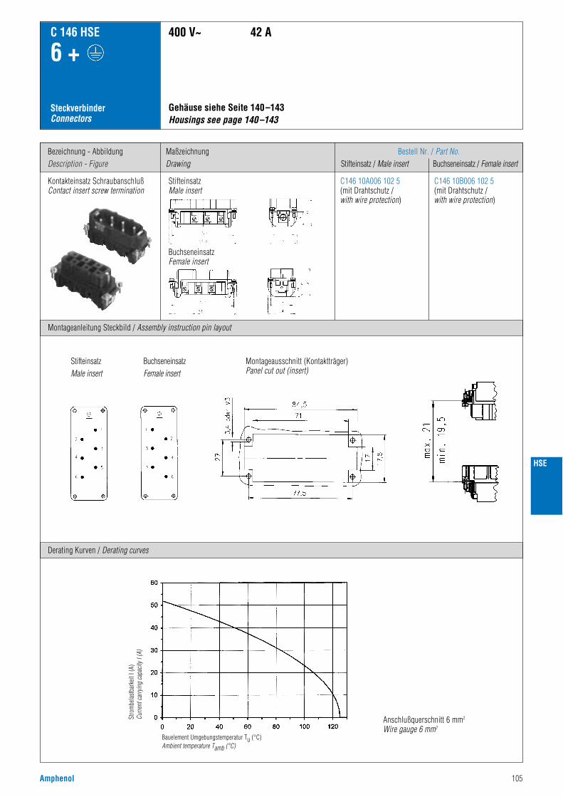
Amphenol 105
Bezeichnung - AbbildungDescription - Figure
Montageanleitung Steckbild / Assembly instruction pin layout
MaßzeichnungDrawing
Bestell Nr. / Part No.Stifteinsatz / Male insert Buchseneinsatz / Female insert
C 146 HSE
6 +
SteckverbinderConnectors
Kontakteinsatz SchraubanschlußContact insert screw termination
StifteinsatzMale insert
BuchseneinsatzFemale insert
Gehäuse siehe Seite 140–143 Housings see page 140–143
400 V~ 42 A
C146 10A006 102 5(mit Drahtschutz /with wire protection)
C146 10B006 102 5(mit Drahtschutz /with wire protection)
Derating Kurven / Derating curves
Anschlußquerschnitt 6 mm2
Wire gauge 6 mm2
Stro
mbe
last
bark
eit I
(A)
Curre
nt c
arry
ing
capa
city
I (A
)
Bauelement Umgebungstemperatur Tu (°C)Ambient temperature Tamb (°C)
HSE
Montageausschnitt (Kontaktträger)Panel cut out (insert)
StifteinsatzMale insert
BuchseneinsatzFemale insert

106 Amphenol
HSE
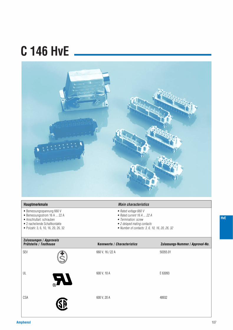
C 146 HvE
• Bemessungsspannung 660 V• Bemessungsstrom 16 A ... 22 A• Anschlußart: schrauben• 2 nacheilende Schaltkontakte• Polzahl: 3, 6, 10, 16, 20, 26, 32
• Rated voltage 660 V• Rated current 16 A ... 22 A• Termination: screw• 2 delayed mating contacts• Number of contacts: 3, 6, 10, 16, 20, 26, 32
Amphenol 107
HvE
Hauptmerkmale Main characteristics
Zulassungen / ApprovalsPrüfstelle / Testhouse Kennwerte / Characteristics Zulassungs-Nummer / Approval-No.
SEV 660 V, 16 / 22 A 50355.01
UL 600 V, 10 A E 63093
CSA 600 V, 20 A 48932
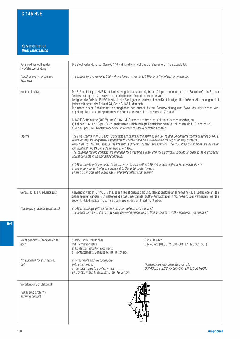
KurzinformationBrief information
C 146 HvE
Konstruktiver Aufbau der HvE-Steckverbindung
Construction of connectors Type HvE
Kontakteinsätze
Inserts
Gehäuse: (aus Alu-Druckguß)
Housings: (made of aluminium)
Verwendet werden C 146 E-Gehäuse mit Isolationsauskleidung. (Isolationsfolie an Innenwand). Die Sperrstege an denGehäuseinnenwänden (Schmalseite), die das Einsetzen der 660 V-Kontaktträger in 400 V-Gehäusen verhindern, werdenentfernt. HvE-Einsätze mit stirnseitigem Sperrstück sind jetzt montierbar.
C 146 E housings with an inside insulation (plastic foil) are used.The inside barriers at the narrow sides preventing mounting of 660 V-inserts in 400 V housings, are removed.
Die 3, 6 und 10-pol. HVE-Kontakteinsätze gehen aus den 10, 16 und 24-pol. Isolierkörpern der Baureihe C 146 E durchTeilbestückung und 2 zusätzlichen, nacheilenden Schaltkontakten hervor.Lediglich die Polzahl 16 HVE besitzt in der Steckgeometrie abweichende Kontaktträger. Ihre äußeren Abmessungen sindjedoch mit denen der Polzahl 24, Serie C 146 E identisch.Die nacheilenden Schaltkontakte ermöglichen den Anschluß einer Schützwicklung zum Zweck der elektrischen Ver-riegelung. Das bedeutet spannungslose Buchseneinsätze im ungesteckten Zustand.
C 146 E-Stifteinsätze (400 V) und C 146 HvE-Buchseneinsätze sind nicht miteinander steckbar, da a) bei den 3, 6 und 10-pol. Buchseneinsätzen 2 nicht belegte Kontaktkammern verschlossen sind. (Blindstopfen).b) die 16-pol. HVE-Kontaktträger eine abweichende Steckgeometrie besitzen.
The HVE-inserts with 3, 6 and 10 contacts are basically the same as the 10, 16 and 24-contacts inserts of series C 146 E.However they are only partly equipped with contacts and have two delayed mating pilot duty contacts.Only type 16 HVE has special inserts with a different contact arrangement. The mounting dimensions are howeveridentical with the 24 contacts version of C 146 E.The delayled mating contacts are intended for switching a realy coil for electrically locking in order to have unloadedsocket contacts in an unmated condition.
C 146 E inserts with pin contacts are not intermatable with C 146 HvE inserts with socket contacts due toa) two empty contactholes are closed at 3, 6 and 10 contact inserts.b) the 16 contacts HVE insert has a different contact arrangement.
Die Steckverbindung der Serie C 146 HvE sind wie folgt aus der Baureihe C 146 E abgeleitet:
The connectors of series C 146 HvE are based on series C 146 E with the following deviations:
Nicht genormte Steckverbinder,aber:
No standard for this series,but:
Steck- und austauschbarmit Fremdfabrikatena) Kontakteinsatz/Kontakteinsatzb) Kontakteinsatz/Gehäuse 6, 10, 16, 24 pol.
Intermateable and exchangeablewith other makesa) Contact insert to contact insert b) Contact insert to housing 6, 10 ,16, 24 pin
Gehäuse nach DIN 43620 (CECC 75 301-801, EN 175 301-801)
Housings are designed according to DIN 43620 (CECC 75 301-801, EN 175 301-801)
Voreilender Schutzkontakt
Preleading protectiv earthing contact
108 Amphenol
HvE
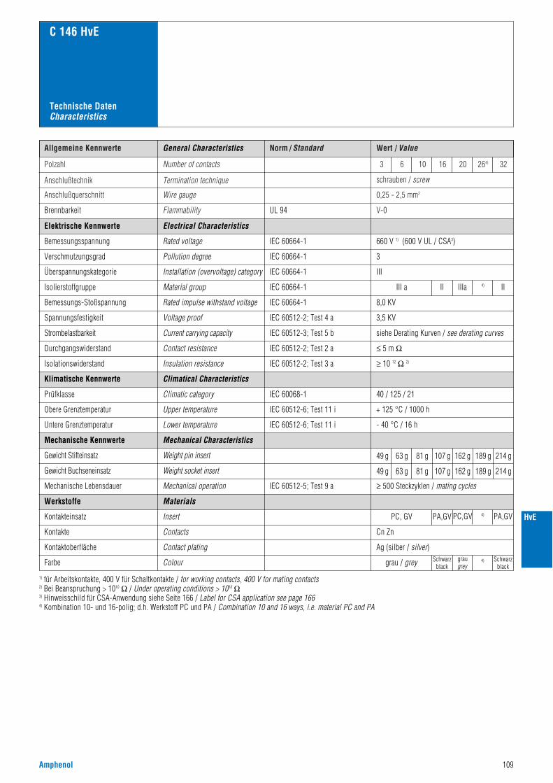
Norm / Standard Wert / ValueAllgemeine Kennwerte
Polzahl Number of contacts
Anschlußtechnik Termination technique
V-0
schrauben / screw
Anschlußquerschnitt Wire gauge 0,25 - 2,5 mm2
3 6 10 16 20 264) 32
Flammability
C 146 HvE
UL 94Brennbarkeit
660 V 1) (600 V UL / CSA3)
3
III
III a II4)IIIaII
8,0 KV
3,5 KV
siehe Derating Kurven / see derating curves
≤ 5 m Ω
Electrical Characteristics
Rated voltage
Pollution degree
Installation (overvoltage) category
Material group
Rated impulse withstand voltage
Voltage proof
IEC 60664-1
IEC 60664-1
IEC 60664-1
IEC 60664-1
IEC 60664-1
IEC 60512-2; Test 4 a
IEC 60512-3; Test 5 b
IEC 60512-2; Test 2 a
IEC 60068-1
Current carrying capacity
Contact resistance
Climatical Characteristics
Climatic category 40 / 125 / 21
Elektrische Kennwerte
Bemessungsspannung
Verschmutzungsgrad
Überspannungskategorie
Isolierstoffgruppe
Bemessungs-Stoßspannung
Spannungsfestigkeit
Strombelastbarkeit
Durchgangswiderstand
≥ 10 12 Ω 2)IEC 60512-2; Test 3 aInsulation resistanceIsolationswiderstand
Klimatische Kennwerte
Prüfklasse
IEC 60512-6; Test 11 iUpper temperature + 125 °C / 1000 hObere Grenztemperatur
IEC 60512-6; Test 11 iLower temperature - 40 °C / 16 hUntere Grenztemperatur
Mechanical Characteristics
grau / grey Schwarzblack
Schwarzblack
Insert
Contacts
Contact plating
PC, GV PA,GV PC,GV
graugrey
4)
4)
PA,GV
Cn Zn
Ag (silber / silver)
IEC 60512-5; Test 9 a
Weight pin insert
Weight socket insert
Mechanical operation
49 g 63 g 81 g 107 g 162 g 189 g 214 g
≥ 500 Steckzyklen / mating cycles
Mechanische Kennwerte
Gewicht Stifteinsatz
Gewicht Buchseneinsatz
Mechanische Lebensdauer
Werkstoffe
Kontakteinsatz
Kontakte
Kontaktoberfläche
Farbe
1) für Arbeitskontakte, 400 V für Schaltkontakte / for working contacts, 400 V for mating contacts2) Bei Beanspruchung > 1010 Ω / Under operating conditions > 1010 Ω3) Hinweisschild für CSA-Anwendung siehe Seite 166 / Label for CSA application see page 1664) Kombination 10- und 16-polig; d.h. Werkstoff PC und PA / Combination 10 and 16 ways, i.e. material PC and PA
Colour
Materials
General Characteristics
Technische DatenCharacteristics
49 g 63 g 81 g 107 g 162 g 189 g 214 g
Amphenol 109
HvE
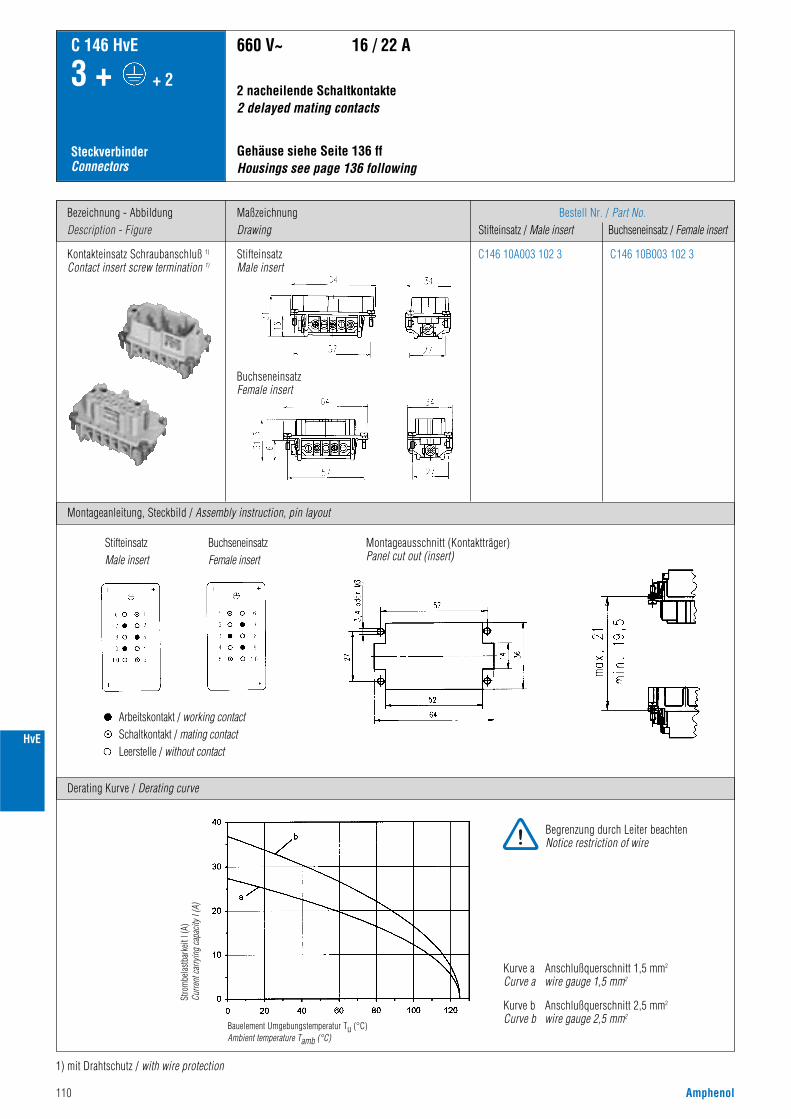
110 Amphenol
HvE
Bezeichnung - AbbildungDescription - Figure
Montageanleitung, Steckbild / Assembly instruction, pin layout
MaßzeichnungDrawing
Bestell Nr. / Part No.Stifteinsatz / Male insert Buchseneinsatz / Female insert
C 146 HvE
3 + + 2
SteckverbinderConnectors
Kontakteinsatz Schraubanschluß 1)
Contact insert screw termination 1)
Gehäuse siehe Seite 136 ffHousings see page 136 following
660 V~ 16 / 22 A
C146 10A003 102 3 C146 10B003 102 3
Derating Kurve / Derating curve
1) mit Drahtschutz / with wire protection
2 nacheilende Schaltkontakte 2 delayed mating contacts
Kurve a Anschlußquerschnitt 1,5 mm2
Curve a wire gauge 1,5 mm2
Kurve b Anschlußquerschnitt 2,5 mm2
Curve b wire gauge 2,5 mm2
StifteinsatzMale insert
BuchseneinsatzFemale insert
Stro
mbe
last
bark
eit I
(A)
Curre
nt c
arry
ing
capa
city
I (A
)
Bauelement Umgebungstemperatur Tu (°C)Ambient temperature Tamb (°C)
Montageausschnitt (Kontaktträger)Panel cut out (insert)
StifteinsatzMale insert
BuchseneinsatzFemale insert
Arbeitskontakt / working contactSchaltkontakt / mating contactLeerstelle / without contact
Begrenzung durch Leiter beachtenNotice restriction of wire
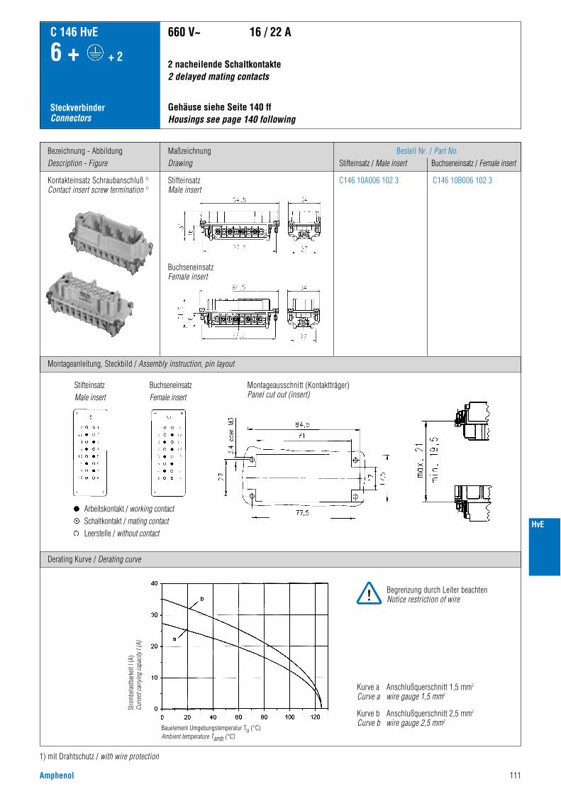
Amphenol 111
HvE
Bezeichnung - AbbildungDescription - Figure
Montageanleitung, Steckbild / Assembly instruction, pin layout
MaßzeichnungDrawing
Bestell Nr. / Part No.Stifteinsatz / Male insert Buchseneinsatz / Female insert
C 146 HvE
6 + + 2
SteckverbinderConnectors
Kontakteinsatz Schraubanschluß 1)
Contact insert screw termination 1)
Gehäuse siehe Seite 140 ffHousings see page 140 following
660 V~ 16 / 22 A
C146 10A006 102 3 C146 10B006 102 3
Derating Kurve / Derating curve
1) mit Drahtschutz / with wire protection
2 nacheilende Schaltkontakte 2 delayed mating contacts
Kurve a Anschlußquerschnitt 1,5 mm2
Curve a wire gauge 1,5 mm2
Kurve b Anschlußquerschnitt 2,5 mm2
Curve b wire gauge 2,5 mm2
StifteinsatzMale insert
BuchseneinsatzFemale insert
Stro
mbe
last
bark
eit I
(A)
Curre
nt c
arry
ing
capa
city
I (A
)
Bauelement Umgebungstemperatur Tu (°C)Ambient temperature Tamb (°C)
Montageausschnitt (Kontaktträger)Panel cut out (insert)
StifteinsatzMale insert
BuchseneinsatzFemale insert
Arbeitskontakt / working contactSchaltkontakt / mating contactLeerstelle / without contact
Begrenzung durch Leiter beachtenNotice restriction of wire
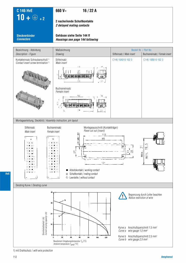
112 Amphenol
HvE
Bezeichnung - AbbildungDescription - Figure
Montageanleitung, Steckbild / Assembly instruction, pin layout
MaßzeichnungDrawing
Bestell Nr. / Part No.Stifteinsatz / Male insert Buchseneinsatz / Female insert
C 146 HvE
10 + + 2
SteckverbinderConnectors
Kontakteinsatz Schraubanschluß 1)
Contact insert screw termination 1)
Gehäuse siehe Seite 144 ffHousings see page 144 following
2 nacheilende Schaltkontakte 2 delayed mating contacts
660 V~ 16 / 22 A
C146 10A010 102 3 C146 10B010 102 3
Derating Kurve / Derating curve
1) mit Drahtschutz / with wire protection
Kurve a Anschlußquerschnitt 1,5 mm2
Curve a wire gauge 1,5 mm2
Kurve b Anschlußquerschnitt 2,5 mm2
Curve b wire gauge 2,5 mm2
StifteinsatzMale insert
BuchseneinsatzFemale insert
Stro
mbe
last
bark
eit I
(A)
Curre
nt c
arry
ing
capa
city
I (A
)
Bauelement Umgebungstemperatur Tu (°C)Ambient temperature Tamb (°C)
Montageausschnitt (Kontaktträger)Panel cut out (insert)
StifteinsatzMale insert
BuchseneinsatzFemale insert
Arbeitskontakt / working contactSchaltkontakt / mating contactLeerstelle / without contact
Begrenzung durch Leiter beachtenNotice restriction of wire
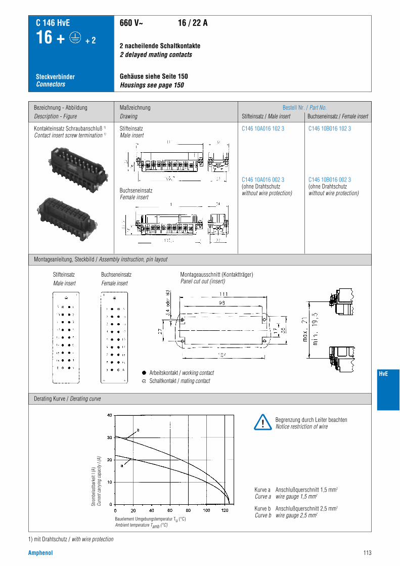
Amphenol 113
HvE
Bezeichnung - AbbildungDescription - Figure
Montageanleitung, Steckbild / Assembly instruction, pin layout
MaßzeichnungDrawing
Bestell Nr. / Part No.Stifteinsatz / Male insert Buchseneinsatz / Female insert
C 146 HvE
16 + + 2
SteckverbinderConnectors
Kontakteinsatz Schraubanschluß 1)
Contact insert screw termination 1)
2 nacheilende Schaltkontakte 2 delayed mating contacts
660 V~ 16 / 22 A
C146 10A016 102 3
C146 10A016 002 3(ohne Drahtschutzwithout wire protection)
C146 10B016 102 3
C146 10B016 002 3(ohne Drahtschutzwithout wire protection)
Derating Kurve / Derating curve
1) mit Drahtschutz / with wire protection
Kurve a Anschlußquerschnitt 1,5 mm2
Curve a wire gauge 1,5 mm2
Kurve b Anschlußquerschnitt 2,5 mm2
Curve b wire gauge 2,5 mm2
Gehäuse siehe Seite 150Housings see page 150
StifteinsatzMale insert
BuchseneinsatzFemale insert
Stro
mbe
last
bark
eit I
(A)
Curre
nt c
arry
ing
capa
city
I (A
)
Bauelement Umgebungstemperatur Tu (°C)Ambient temperature Tamb (°C)
Montageausschnitt (Kontaktträger)Panel cut out (insert)
StifteinsatzMale insert
BuchseneinsatzFemale insert
Arbeitskontakt / working contactSchaltkontakt / mating contact
Begrenzung durch Leiter beachtenNotice restriction of wire
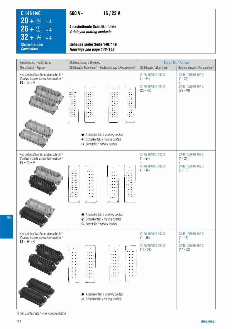
114 Amphenol
HvE
Bezeichnung - AbbildungDescription - Figure
Maßzeichnung / DrawingStifteinsatz / Male insert Buchseneinsatz / Female insert
Bestell Nr. / Part No.Stifteinsatz / Male insert Buchseneinsatz / Female insert
C 146 HvE
20 + + 4
26 + + 4
32 + + 4SteckverbinderConnectors
Gehäuse siehe Seite 148/149 Housings see page 148/149
4 nacheilende Schaltkontakte 4 delayed mating contacts
660 V~ 16 / 22 A
1) mit Drahtschutz / with wire protection
Kontakteinsätze Schraubanschluß 1)
Contact inserts screw termination 1)
20 + + 4
C146 10A010 102 3(1 - 24)+C146 10A010 104 3(25 - 48)
C146 10B010 102 3(1 - 24)+C146 10B010 104 3(25 - 48)
Kontakteinsätze Schraubanschluß 1)
Contact inserts screw termination 1)
26 + + 4
Kontakteinsätze Schraubanschluß 1)
Contact inserts screw termination 1)
32 + + 4
C146 10A010 102 3(1 - 24)+C146 10A016 102 3(1 - 16)
C146 10A016 102 3(1 - 16)+C146 10A016 104 3(17 - 32)
C146 10A010 102 3(1 - 24)+C146 10B016 102 3(1 - 16)
C146 10B016 102 3(1 - 16)+C146 10B016 104 3(17 - 32)
Arbeitskontakt / working contactSchaltkontakt / mating contactLeerstelle / without contact
Arbeitskontakt / working contactSchaltkontakt / mating contactLeerstelle / without contact
Arbeitskontakt / working contactSchaltkontakt / mating contact
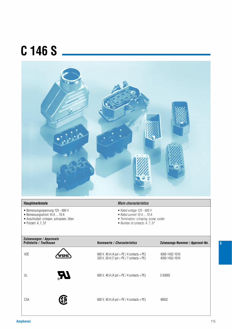
Amphenol 115
C 146 S
• Bemessungsspannung 125 - 600 V• Bemessungsstrom 10 A ... 70 A• Anschlußart: crimpen, schrauben, löten• Polzahl: 4, 7, 57
• Rated voltage 125 - 600 V• Rated current 10 A ... 70 A• Termination: crimping, screw, solder• Number of contacts: 4, 7, 57
S
Hauptmerkmale Main characteristics
Zulassungen / ApprovalsPrüfstelle / Testhouse Kennwerte / Characteristics Zulassungs-Nummer / Approval-No.
VDE 660 V, 40 A (4 pol + PE / 4 contacts + PE) 4260-1432-1010320 V, 30 A (7 pol + PE / 7 contacts + PE) 4260-1432-1010
UL 600 V, 40 A (4 pol + PE / 4 contacts + PE) E 63093
CSA 600 V, 40 A (4 pol + PE / 4 contacts + PE) 48932
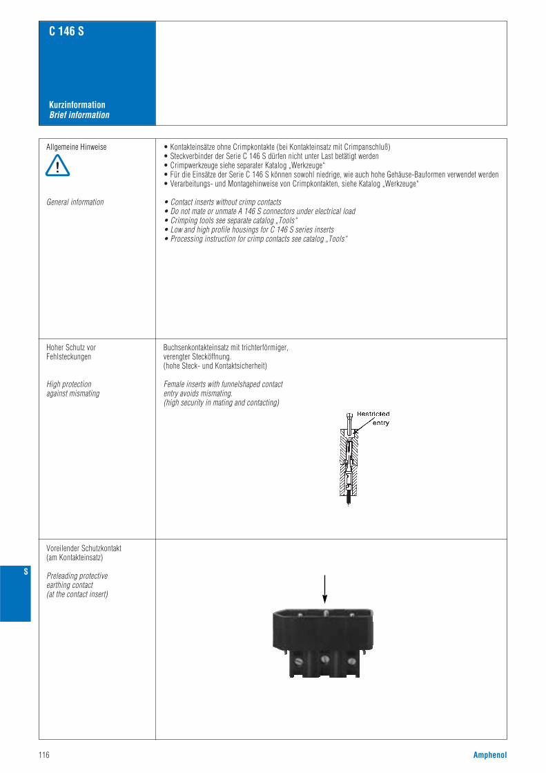
116 Amphenol
KurzinformationBrief information
C 146 S
Allgemeine Hinweise
General information
• Kontakteinsätze ohne Crimpkontakte (bei Kontakteinsatz mit Crimpanschluß)• Steckverbinder der Serie C 146 S dürfen nicht unter Last betätigt werden• Crimpwerkzeuge siehe separater Katalog „Werkzeuge“• Für die Einsätze der Serie C 146 S können sowohl niedrige, wie auch hohe Gehäuse-Bauformen verwendet werden• Verarbeitungs- und Montagehinweise von Crimpkontakten, siehe Katalog „Werkzeuge“
• Contact inserts without crimp contacts• Do not mate or unmate A 146 S connectors under electrical load• Crimping tools see separate catalog „Tools“• Low and high profile housings for C 146 S series inserts• Processing instruction for crimp contacts see catalog „Tools“
Hoher Schutz vorFehlsteckungen
High protectionagainst mismating
Buchsenkontakteinsatz mit trichterförmiger,verengter Stecköffnung.(hohe Steck- und Kontaktsicherheit)
Female inserts with funnelshaped contact entry avoids mismating.(high security in mating and contacting)
Voreilender Schutzkontakt(am Kontakteinsatz)
Preleading protectiveearthing contact(at the contact insert)
S
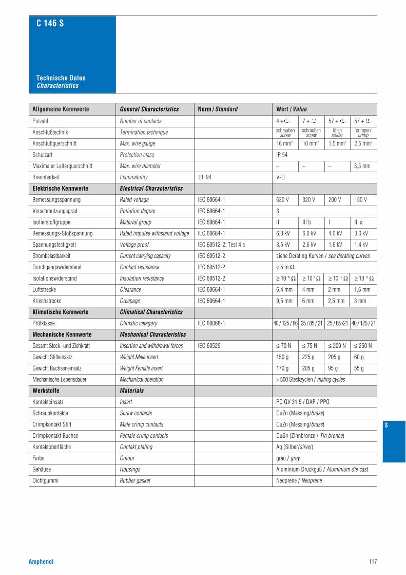
Amphenol 117
Norm / Standard Wert / ValueAllgemeine Kennwerte
Polzahl Number of contacts
Anschlußtechnik Termination technique schraubenscrew
schraubenscrew
lötensolder
crimpencrimp
Anschlußquerschnitt
Maximaler Leiterquerschnitt
Max. wire gauge
Schutzart Protection class
Max. wire diameter – – – 3,5 mm
Brennbarkeit Flammability V-OUL 94
4 + 7 + 57 + 57 +
16 mm2
IP 54
10 mm2 1,5 mm2 2,5 mm2
630 V 320 V 200 V 150 V
III b I III a
6,0 kV 4,0 kV 3,0 kV
2,6 kV 1,6 kV 1,4 kV
≥ 10 9 Ω ≥ 10 10 Ω ≥ 10 10 Ω
C 146 S
PC GV 31,5 / DAP / PPO
grau / grey
> 500 Steckzyclen / mating cycles
CuZn (Messing/brass)
Ag (Silber/silver)
3
II
6,0 kV
3,5 kV
siehe Derating Kurven / see derating curves
< 5 m Ω
IEC 60664-1
IEC 60664-1
IEC 60664-1
IEC 60664-1
IEC 60512-2; Test 4 a
IEC 60512-2
IEC 60512-2
IEC 60068-1
IEC 60529
40 / 125 / 66
≤ 70 N ≤ 75 N ≤ 200 N ≤ 250 N
150 g 225 g 205 g 60 g
170 g 205 g 95 g 55 g
25 / 85 / 21 25 / 85 /21 40 / 125 / 21
≥ 10 10 ΩIEC 60512-2
IEC 60664-1 6,4 mm 4 mm 2 mm 1,6 mm
9,5 mm 6 mm 2,5 mm 3 mmIEC 60664-1
Electrical Characteristics
Rated voltage
Pollution degree
Material group
Rated impulse withstand voltage
Voltage proof
Current carrying capacity
Contact resistance
Climatical Characteristics
Climatic category
Mechanical Characteristics
Insertion and withdrawal forces
Weight Male insert
Weight Female insert
Insert
Insulation resistance
Clearance
Creepage
Mechanical operation
Screw contacts
Contakt plating
Elektrische Kennwerte
Bemessungsspannung
Verschmutzungsgrad
Isolierstoffgruppe
Bemessungs-Stoßspannung
Spannungsfestigkeit
Strombelastbarkeit
Durchgangswiderstand
Isolationswiderstand
Luftstrecke
Kriechstrecke
Klimatische Kennwerte
Prüfklasse
Mechanische Kennwerte
Gesamt Steck- und Ziehkraft
Gewicht Stifteinsatz
Gewicht Buchseneinsatz
Mechanische Lebensdauer
Werkstoffe
Kontakteinsatz
Schraubkontakte
CuZn (Messing/brass)Male crimp contactsCrimpkontakt Stift
CuSn (Zinnbronze / Tin bronce)Female crimp contactsCrimpkontakt Buchse
Kontaktoberfläche
Farbe Colour
Aluminium Druckguß / Aluminium die castGehäuse Housings
Neoprene / NeopreneDichtgummi Rubber gasket
Materials
General Characteristics
Technische DatenCharacteristics
S
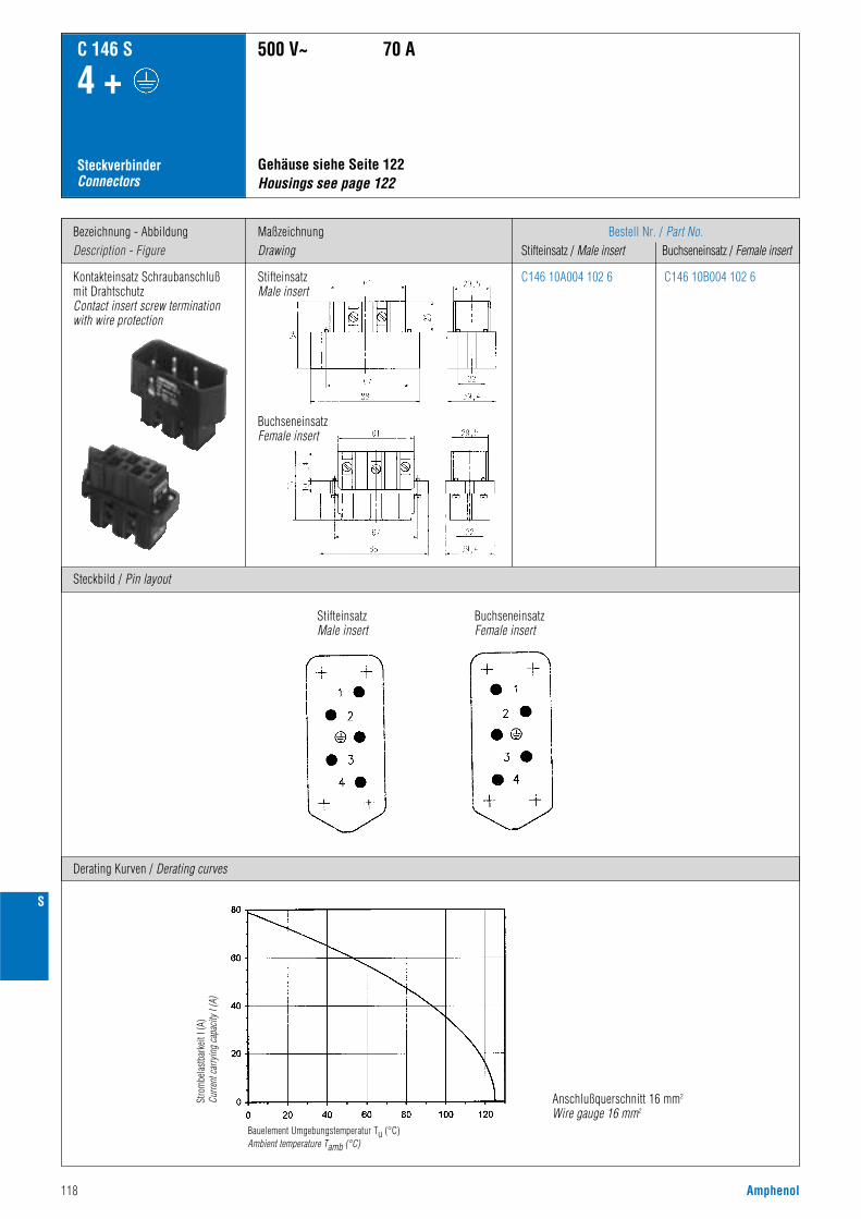
118 Amphenol
S
Bezeichnung - AbbildungDescription - Figure
Steckbild / Pin layout
MaßzeichnungDrawing
Bestell Nr. / Part No.Stifteinsatz / Male insert Buchseneinsatz / Female insert
C 146 S
4 +
SteckverbinderConnectors
Kontakteinsatz Schraubanschlußmit DrahtschutzContact insert screw terminationwith wire protection
StifteinsatzMale insert
BuchseneinsatzFemale insert
Gehäuse siehe Seite 122 Housings see page 122
500 V~ 70 A
Derating Kurven / Derating curves
C146 10A004 102 6 C146 10B004 102 6
Anschlußquerschnitt 16 mm2
Wire gauge 16 mm2
StifteinsatzMale insert
BuchseneinsatzFemale insert
Stro
mbe
last
bark
eit I
(A)
Curre
nt c
arry
ing
capa
city
I (A
)
Bauelement Umgebungstemperatur Tu (°C)Ambient temperature Tamb (°C)
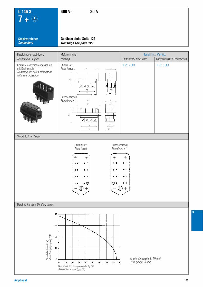
Amphenol 119
S
Bezeichnung - AbbildungDescription - Figure
Steckbild / Pin layout
MaßzeichnungDrawing
Bestell Nr. / Part No.Stifteinsatz / Male insert Buchseneinsatz / Female insert
C 146 S
7 +
SteckverbinderConnectors
Kontakteinsatz Schraubanschlußmit DrahtschutzContact insert screw terminationwith wire protection
StifteinsatzMale insert
BuchseneinsatzFemale insert
400 V~ 30 A
Derating Kurven / Derating curves
T 2517 000 T 2518 000
Anschlußquerschnitt 10 mm2
Wire gauge 10 mm2
Gehäuse siehe Seite 122 Housings see page 122
StifteinsatzMale insert
BuchseneinsatzFemale insert
Stro
mbe
last
bark
eit I
(A)
Curre
nt c
arry
ing
capa
city
I (A
)
Bauelement Umgebungstemperatur Tu (°C)Ambient temperature Tamb (°C)
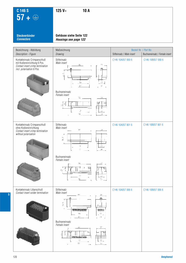
120 Amphenol
S
Bezeichnung - AbbildungDescription - Figure
MaßzeichnungDrawing
Bestell Nr. / Part No.Stifteinsatz / Male insert Buchseneinsatz / Female insert
C 146 S
57 +
SteckverbinderConnectors
Kontakteinsatz Crimpanschlußmit Kodiereinrichtung 6 Pos.Contact insert crimp terminationincl. polarisation 6 Pos.
125 V~ 10 A
C146 10A057 000 6 C146 10B057 000 6
Kontakteinsatz Crimpanschlußohne KodiereinrichtungContact insert crimp terminationwithout polarisation
Kontakteinsatz LötanschlußContact insert solder termination
C146 10A057 801 6 C146 10B057 801 6
C146 10A057 006 6 C146 10B057 006 6
StifteinsatzMale insert
BuchseneinsatzFemale insert
BuchseneinsatzFemale insert
BuchseneinsatzFemale insert
Gehäuse siehe Seite 122 Housings see page 122
StifteinsatzMale insert
StifteinsatzMale insert
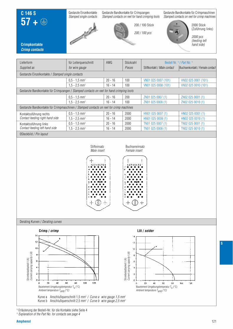
Amphenol 121
S
1) Erläuterung der Bestell-Nr. für die Kontakte siehe Seite 41) Explanation of the Part No. for contacts see page 4
Gestanzte Einzelkontakte / Stamped single contacts
Gestanzte Bandkontakte für Crimpzangen / Stamped contacts on reel for hand crimping tools
Gestanzte Bandkontakte für Crimpmaschinen / Stamped contacts on reel for crimp machines
LieferformSupplied as
AWGfür Leiterquerschnittfor wire gauge
StückzahlPieces
Bestell Nr. 1) / Part No. 1)
Stiftkontakt / Male contact Buchsenkontakt / Female contact
CrimpkontakteCrimp contacts
C 146 S
57 +
0,5 - 1,5 mm2
1,5 - 2,5 mm2
0,5 - 1,5 mm2
1,5 - 2,5 mm2
0,5 - 1,5 mm2
1,5 - 2,5 mm2
0,5 - 1,5 mm2
1,5 - 2,5 mm2
20 - 1616 - 1420 - 1616 - 14
20 - 1616 - 14
20 - 1616 - 14
2000200020002000
200100
100100
HN01 025 0007 (1)HN01 025 0008 (1)TN01 025 0007 (1)TN01 025 0008 (1)
ZN01 025 0007 (1)ZN01 025 0008 (1)
VN01 025 0007 (101)VN01 025 0008 (101)
HN02 025 0001 (1)HN02 025 0010 (1)TN02 025 0001 (1)TN02 025 0010 (1)
ZN02 025 0001 (1)ZN02 025 0010 (1)
VN02 025 0001 (101)VN02 025 0010 (101)
Kontaktzuführung rechtsContact feeding right hand side
Kontaktzuführung linksContact feeding left hand side
0Steckbild / Pin layout
Derating Kurven / Derating curves
Crimp / crimp Löt / solder
Gestanzte Bandkontakte für CrimpmaschinenStamped contacts on reel for crimp machines
200 / 100 Stück
200 / 100 pcs
2000 Stück(Zuführung links)
2000 pcs(feeding lefthand side)
Gestanzte EinzelkontakteStamped single contacts
Gestanzte Bandkontakte für CrimpzangenStamped contacts on reel for hand crimping tools
Kurve a Anschlußquerschnitt 1,5 mm2 / Curve a wire gauge 1,5 mm2
Kurve b Anschlußquerschnitt 2,5 mm2 / Curve b wire gauge 2,5 mm2
Stro
mbe
last
bark
eit I
(A)
Curre
nt c
arry
ing
capa
city
I (A
)
Bauelement Umgebungstemperatur Tu (°C)Ambient temperature Tamb (°C)
Stro
mbe
last
bark
eit I
(A)
Curre
nt c
arry
ing
capa
city
I (A
)
Bauelement Umgebungstemperatur Tu (°C)Ambient temperature Tamb (°C)
StifteinsatzMale insert
BuchseneinsatzFemale insert
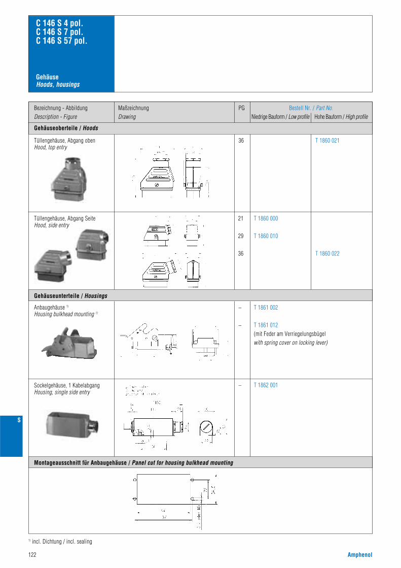
122 Amphenol
S
Gehäuseoberteile / Hoods
Bezeichnung - AbbildungDescription - Figure
MaßzeichnungDrawing
PG Bestell Nr. / Part No.Niedrige Bauform / Low profile Hohe Bauform / High profile
36 T 1860 021
GehäuseHoods, housings
C 146 S 4 pol.C 146 S 7 pol.C 146 S 57 pol.
Gehäuseunterteile / Housings
Montageausschnitt für Anbaugehäuse / Panel cut for housing bulkhead mounting
Tüllengehäuse, Abgang obenHood, top entry
21
29
36
T 1860 000
T 1860 010
T 1860 022
Tüllengehäuse, Abgang SeiteHood, side entry
–
–
–
T 1862 001
T 1861 002
T 1861 012(mit Feder am Verriegelungsbügelwith spring cover on locking lever)
Anbaugehäuse 1)
Housing bulkhead mounting 1)
Sockelgehäuse, 1 KabelabgangHousing, single side entry
1) incl. Dichtung / incl. sealing
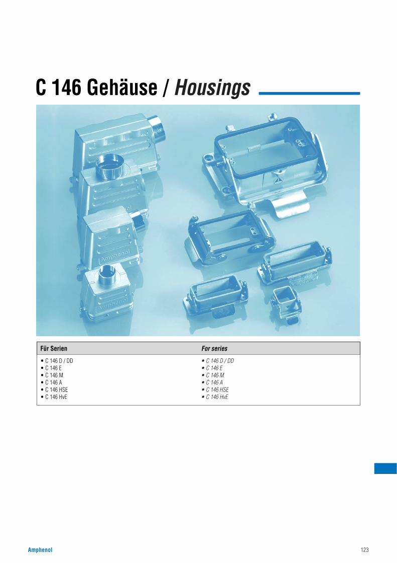
Amphenol 123
C 146 Gehäuse / Housings
• C 146 D / DD• C 146 E• C 146 M• C 146 A• C 146 HSE• C 146 HvE
• C 146 D / DD• C 146 E• C 146 M• C 146 A• C 146 HSE• C 146 HvE
Für Serien For series
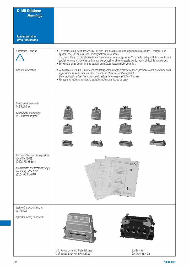
124 Amphenol
KurzinformationBrief information
C 146 GehäuseHousings
Allgemeine Hinweise
General information
• Die Steckverbindungen der Serie C 146 sind für Einsatzbereiche im allgemeinen Maschinen-, Anlagen- undApparatebau, Steuerungs- und Elektrogerätebau vorgesehen.Die Überprüfung, ob die Steckverbindung anderen als den angegebenen Vorschriften entspricht, bzw. ob diese inspeziell von uns nicht vorhersehbaren Anwendungsbereichen eingesetzt werden kann, obliegt dem Anwender.
• Bei Kupplungsgehäusen ist eine ausreichende Zugentlastung sicherzustellen.
• The connectors of our C 146 series are designed for the use in maschine tools, general electric installations andapplications as well as for industrial control and other electrical equipment.Other applications than the above mentioned are in the responsibility of the user.
• For cable to cable connections a suitable cable clamp has to be used.
Große Gehäuseauswahlin 2 Bauhöhen
Large range of housingsin 2 different heights
Genormte Steckverbindergehäusenach DIN 43652 (CECC-75301-801)
Standardised connector housingsaccording DIN 43652 (CECC-75301-801)
Weitere Sonderausführung auf Anfrage
Special housing on request
z. B. Korrosions geschützte Gehäusee. G. corrosion protected housings
SondertypenCustomer specials
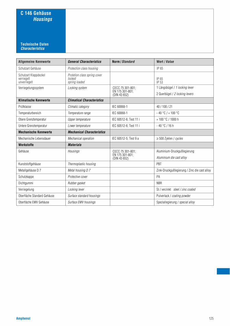
Amphenol 125
Norm / Standard Wert / ValueAllgemeine Kennwerte
Schutzart Gehäuse Protection class housing
Schutzart Klappdeckelverriegeltunverriegelt
Protetion class spring coverlockedspring loaded
IP 65IP 53
IP 65
C 146 GehäuseHousings
Verriegelungssystem Locking system CECC 75 301-801;EN 175 301-801;(DIN 43 652)
1 Längsbügel / 1 locking lever
2 Querbügel / 2 locking levers
IEC 60068-1
Climatical Characteristics
Climatic category 40 / 100 / 21
Klimatische Kennwerte
Prüfklasse
IEC 60068-1Temperature range - 40 °C / + 100 °CTemperaturbereich
IEC 60512-6; Test 11 iUpper temperature + 100 °C / 1000 hObere Grenztemperatur
IEC 60512-6; Test 11 iLower temperature - 40 °C / 16 hUntere Grenztemperatur
Mechanical Characteristics
Zink-Druckgußlegierung / Zinc die cast alloy
Housings
Thermoplastic housing
≥ 500 Zyklen / cycles
Aluminium-Druckgußlegierung
Aluminium die cast alloy
PBT
IEC 60512-5; Test 9 aMechanical operation
Mechanische Kennwerte
Mechanische Lebensdauer
Werkstoffe
Gehäuse
Kunststoffgehäuse
Metallgehäuse D 7 Metal housing D 7
PASchutzkappe Protective cover
NBRDichtgummi Rubber gasket
St / verzinkt steel / zinc coatedVerriegelung Locking lever
Pulverlack / coating powderOberfläche Standard Gehäuse Surface standard housings
Speziallegierung / special alloyOberfläche EMV Gehäuse Surface EMV housings
Materials
General Characteristics
Technische DatenCharacteristics
CECC 75 301-801;EN 175 301-801;(DIN 43 652)
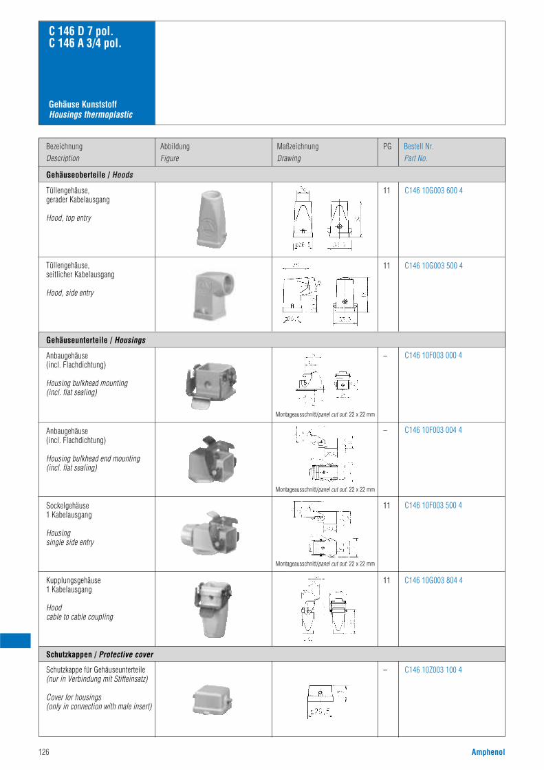
126 Amphenol
Gehäuseoberteile / Hoods
BezeichnungDescription
AbbildungFigure
PGMaßzeichnungDrawing
Bestell Nr.Part No.
11 C146 10G003 600 4
C 146 D 7 pol.C 146 A 3/4 pol.
Gehäuse KunststoffHousings thermoplastic
Gehäuseunterteile / Housings
Schutzkappen / Protective cover
Tüllengehäuse,gerader Kabelausgang
Hood, top entry
11 C146 10G003 500 4Tüllengehäuse,seitlicher Kabelausgang
Hood, side entry
– C146 10F003 000 4Anbaugehäuse(incl. Flachdichtung)
Housing bulkhead mounting(incl. flat sealing)
– C146 10F003 004 4Anbaugehäuse(incl. Flachdichtung)
Housing bulkhead end mounting(incl. flat sealing)
11 C146 10F003 500 4Sockelgehäuse1 Kabelausgang
Housingsingle side entry
11
–
C146 10G003 804 4
C146 10Z003 100 4
Kupplungsgehäuse1 Kabelausgang
Hoodcable to cable coupling
Schutzkappe für Gehäuseunterteile(nur in Verbindung mit Stifteinsatz)
Cover for housings(only in connection with male insert)
Montageausschnitt/panel cut out: 22 x 22 mm
Montageausschnitt/panel cut out: 22 x 22 mm
Montageausschnitt/panel cut out: 22 x 22 mm
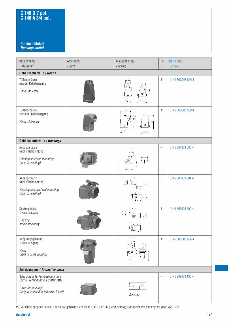
Amphenol 127
Gehäuseoberteile / Hoods
BezeichnungDescription
AbbildungFigure
PGMaßzeichnungDrawing
Bestell Nr.Part No.
11
C 146 D 7 pol.C 146 A 3/4 pol.
Gehäuse MetallHousings metal
Gehäuseunterteile / Housings
Schutzkappen / Protective cover
Tüllengehäuse,gerader Kabelausgang
Hood, top entry
11Tüllengehäuse,seitlicher Kabelausgang
Hood, side entry
–Anbaugehäuse(incl. Flachdichtung)
Housing bulkhead mounting(incl. flat sealing)
–Anbaugehäuse(incl. Flachdichtung)
Housing bulkhead end mounting(incl. flat sealing)
11Sockelgehäuse1 Kabelausgang
Housingsingle side entry
11
– C146 30Z003 100 4
Kupplungsgehäuse1 Kabelausgang
Hoodcable to cable coupling
Schutzkappe für Gehäuseunterteile(nur in Verbindung mit Stifteinsatz)
Cover for housings(only in connection with male insert)
C146 30G003 600 4
C146 30G003 500 4
C146 30F003 000 4
C146 30F003 004 4
C146 30F003 500 4
C146 30G003 804 4
PG Verschraubung für Tüllen- und Sockelgehäuse siehe Seite 160–163 / PG gland bushings for hoods and housing see page 160–163
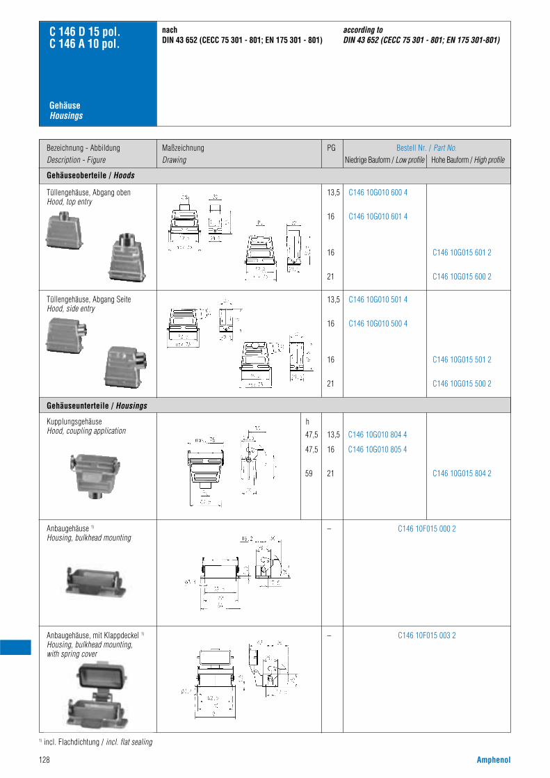
128 Amphenol
Gehäuseoberteile / Hoods
Bezeichnung - AbbildungDescription - Figure
MaßzeichnungDrawing
PG Bestell Nr. / Part No.Niedrige Bauform / Low profile Hohe Bauform / High profile
13,5
16
16
21
C146 10G010 600 4
C146 10G010 601 4
C146 10G015 601 2
C146 10G015 600 2
GehäuseHousings
C 146 D 15 pol.C 146 A 10 pol.
Gehäuseunterteile / Housings
Tüllengehäuse, Abgang obenHood, top entry
13,5
16
16
21
C146 10G010 501 4
C146 10G010 500 4
C146 10G015 501 2
C146 10G015 500 2
Tüllengehäuse, Abgang SeiteHood, side entry
–
13,5
16
21
h
47,5
47,5
59
C146 10F015 000 2
C146 10G010 804 4
C146 10G010 805 4
C146 10G015 804 2
KupplungsgehäuseHood, coupling application
Anbaugehäuse 1)
Housing, bulkhead mounting
– C146 10F015 003 2Anbaugehäuse, mit Klappdeckel 1)
Housing, bulkhead mounting, with spring cover
nachDIN 43 652 (CECC 75 301 - 801; EN 175 301 - 801)
according to DIN 43 652 (CECC 75 301 - 801; EN 175 301-801)
1) incl. Flachdichtung / incl. flat sealing
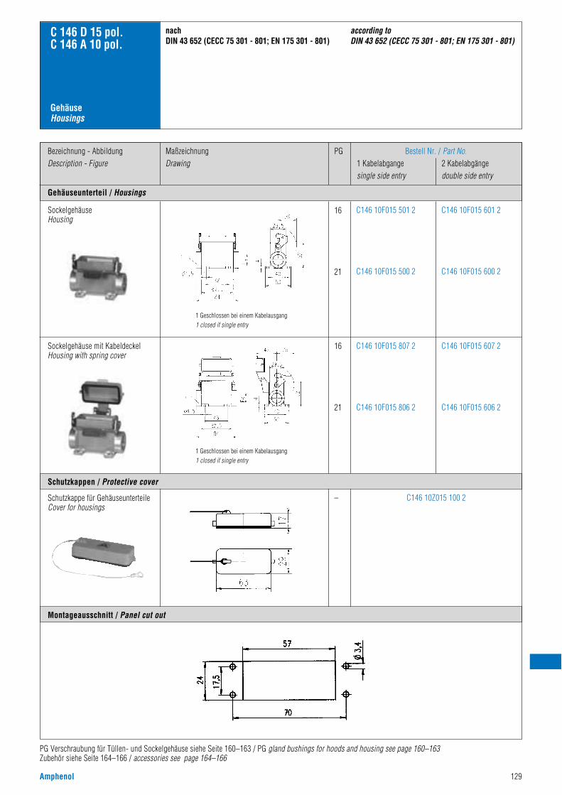
Amphenol 129
Gehäuseunterteil / Housings
Bezeichnung - AbbildungDescription - Figure
MaßzeichnungDrawing
PG Bestell Nr. / Part No.1 Kabelabgange 2 Kabelabgängesingle side entry double side entry
SockelgehäuseHousing
16
21
C146 10F015 601 2
C146 10F015 600 2
C146 10F015 501 2
C146 10F015 500 2
Sockelgehäuse mit KabeldeckelHousing with spring cover
16
21
C146 10F015 607 2
C146 10F015 606 2
C146 10F015 807 2
C146 10F015 806 2
– C146 10Z015 100 2
GehäuseHousings
C 146 D 15 pol.C 146 A 10 pol.
Schutzkappen / Protective cover
Montageausschnitt / Panel cut out
PG Verschraubung für Tüllen- und Sockelgehäuse siehe Seite 160–163 / PG gland bushings for hoods and housing see page 160–163Zubehör siehe Seite 164–166 / accessories see page 164–166
nachDIN 43 652 (CECC 75 301 - 801; EN 175 301 - 801)
according to DIN 43 652 (CECC 75 301 - 801; EN 175 301 - 801)
Schutzkappe für GehäuseunterteileCover for housings
1 Geschlossen bei einem Kabelausgang1 closed if single entry
1 Geschlossen bei einem Kabelausgang1 closed if single entry
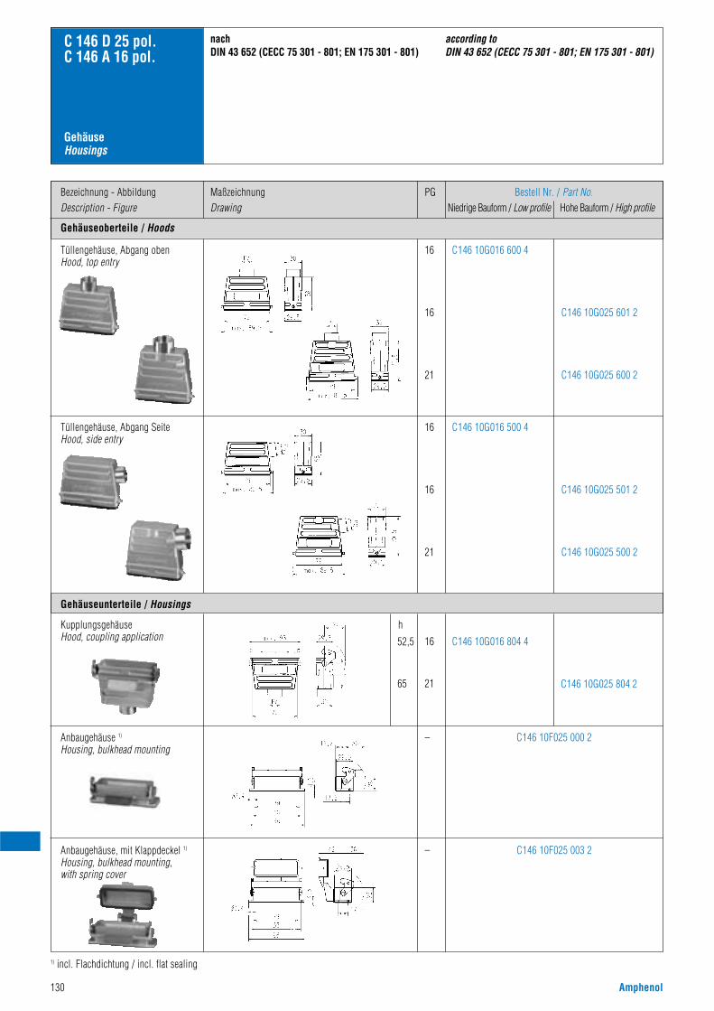
130 Amphenol
Gehäuseoberteile / Hoods
Bezeichnung - AbbildungDescription - Figure
MaßzeichnungDrawing
PG Bestell Nr. / Part No.Niedrige Bauform / Low profile Hohe Bauform / High profile
16
16
21
C146 10G016 600 4
C146 10G025 601 2
C146 10G025 600 2
GehäuseHousings
C 146 D 25 pol.C 146 A 16 pol.
Gehäuseunterteile / Housings
Tüllengehäuse, Abgang obenHood, top entry
16
16
21
C146 10G016 500 4
C146 10G025 501 2
C146 10G025 500 2
Tüllengehäuse, Abgang SeiteHood, side entry
–
16
21
h
52,5
65
C146 10F025 000 2
C146 10G016 804 4
C146 10G025 804 2
KupplungsgehäuseHood, coupling application
Anbaugehäuse 1)
Housing, bulkhead mounting
– C146 10F025 003 2Anbaugehäuse, mit Klappdeckel 1)
Housing, bulkhead mounting, with spring cover
1) incl. Flachdichtung / incl. flat sealing
nachDIN 43 652 (CECC 75 301 - 801; EN 175 301 - 801)
according to DIN 43 652 (CECC 75 301 - 801; EN 175 301 - 801)
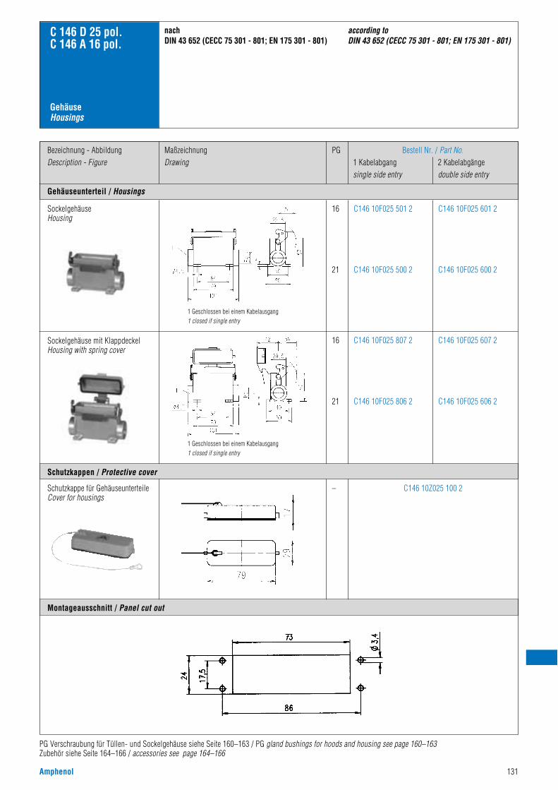
Amphenol 131
Gehäuseunterteil / Housings
Bezeichnung - AbbildungDescription - Figure
MaßzeichnungDrawing
PG Bestell Nr. / Part No.1 Kabelabgang 2 Kabelabgängesingle side entry double side entry
SockelgehäuseHousing
16
21
C146 10F025 601 2
C146 10F025 600 2
C146 10F025 501 2
C146 10F025 500 2
Sockelgehäuse mit KlappdeckelHousing with spring cover
16
21
C146 10F025 607 2
C146 10F025 606 2
C146 10F025 807 2
C146 10F025 806 2
– C146 10Z025 100 2Schutzkappe für GehäuseunterteileCover for housings
GehäuseHousings
C 146 D 25 pol.C 146 A 16 pol.
Schutzkappen / Protective cover
Montageausschnitt / Panel cut out
PG Verschraubung für Tüllen- und Sockelgehäuse siehe Seite 160–163 / PG gland bushings for hoods and housing see page 160–163Zubehör siehe Seite 164–166 / accessories see page 164–166
nachDIN 43 652 (CECC 75 301 - 801; EN 175 301 - 801)
according to DIN 43 652 (CECC 75 301 - 801; EN 175 301 - 801)
1 Geschlossen bei einem Kabelausgang1 closed if single entry
1 Geschlossen bei einem Kabelausgang1 closed if single entry
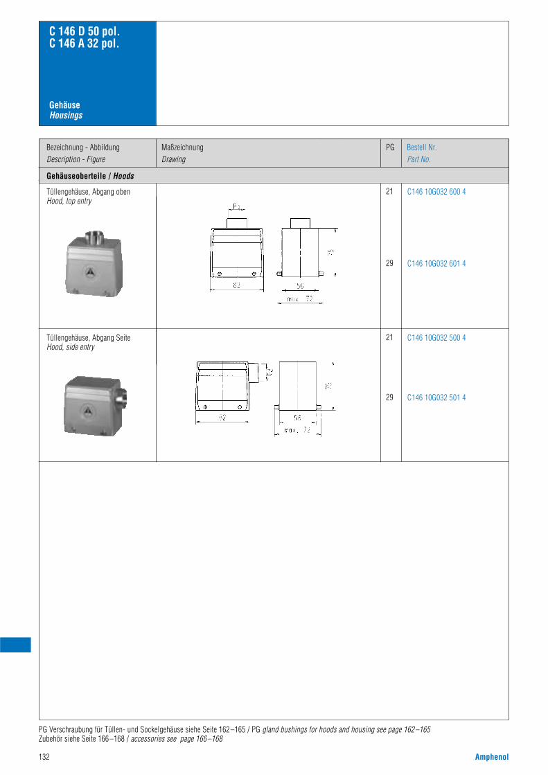
132 Amphenol
Tüllengehäuse, Abgang obenHood, top entry
21
29
C146 10G032 600 4
C146 10G032 601 4
Tüllengehäuse, Abgang SeiteHood, side entry
21
29
C146 10G032 500 4
C146 10G032 501 4
C 146 D 50 pol.C 146 A 32 pol.
Gehäuseoberteile / Hoods
Bezeichnung - AbbildungDescription - Figure
PGMaßzeichnungDrawing
Bestell Nr.Part No.
GehäuseHousings
PG Verschraubung für Tüllen- und Sockelgehäuse siehe Seite 162 –165 / PG gland bushings for hoods and housing see page 162–165Zubehör siehe Seite 166 –168 / accessories see page 166 –168
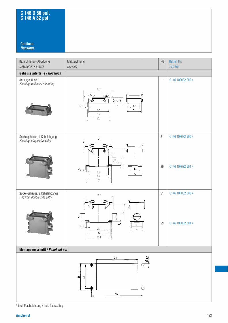
Amphenol 133
Anbaugehäuse 1)
Housing, bulkhead mounting– C146 10F032 000 4
Sockelgehäuse, 1 KabelabgangHousing, single side entry
21
29
C146 10F032 500 4
C146 10F032 501 4
Sockelgehäuse, 2 KabelabgängeHousing, double side entry
1) incl. Flachdichtung / incl. flat sealing
21
29
C146 10F032 600 4
C146 10F032 601 4
C 146 D 50 pol.C 146 A 32 pol.
Gehäuseunterteile / Housings
Bezeichnung - AbbildungDescription - Figure
PGMaßzeichnungDrawing
Bestell Nr.Part No.
Montageausschnitt / Panel cut out
GehäuseHousings
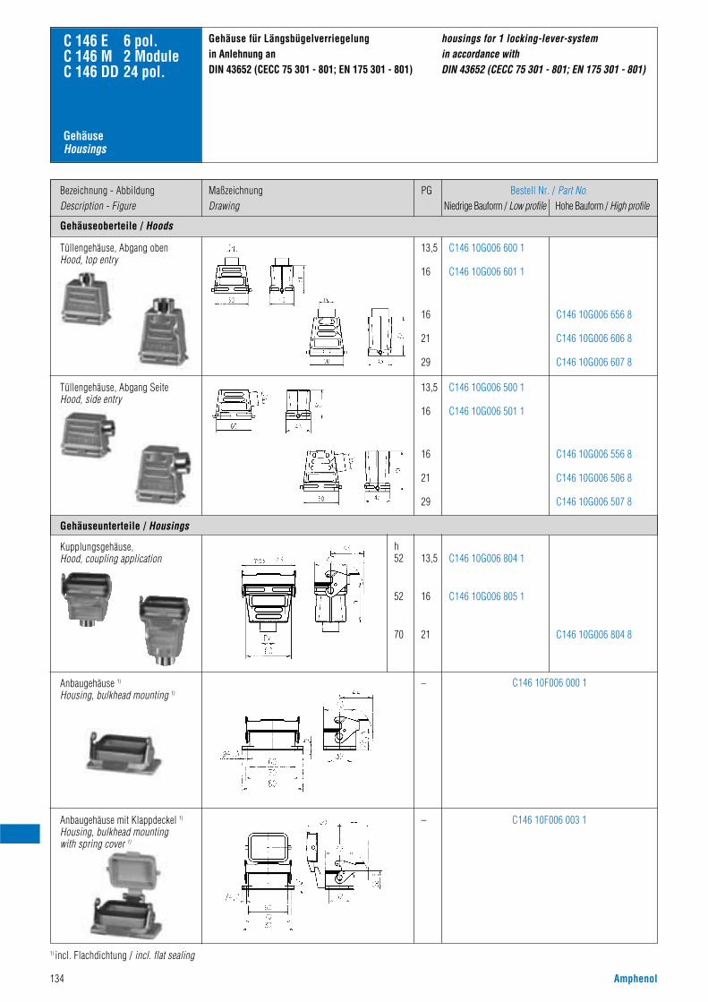
134 Amphenol
Gehäuseoberteile / Hoods
Bezeichnung - AbbildungDescription - Figure
Gehäuse für Längsbügelverriegelung in Anlehnung anDIN 43652 (CECC 75 301 - 801; EN 175 301 - 801)
housings for 1 locking-lever-system in accordance withDIN 43652 (CECC 75 301 - 801; EN 175 301 - 801)
MaßzeichnungDrawing
PG Bestell Nr. / Part No.Niedrige Bauform / Low profile Hohe Bauform / High profile
13,5
16
16
21
29
13,5
16
16
21
29
C146 10G006 600 1
C146 10G006 601 1
C146 10G006 500 1
C146 10G006 501 1
C146 10G006 656 8
C146 10G006 606 8
C146 10G006 607 8
C146 10G006 556 8
C146 10G006 506 8
C146 10G006 507 8
C 146 E 6 pol.C 146 M 2 ModuleC 146 DD 24 pol.
Gehäuseunterteile / Housings
Tüllengehäuse, Abgang obenHood, top entry
13,5
16
21
h52
52
70
C146 10G006 804 1
C146 10G006 805 1
C146 10G006 804 8
Kupplungsgehäuse,Hood, coupling application
–
–
C146 10F006 003 1
C146 10F006 000 1Anbaugehäuse 1)
Housing, bulkhead mounting 1)
1) incl. Flachdichtung / incl. flat sealing
Tüllengehäuse, Abgang SeiteHood, side entry
Anbaugehäuse mit Klappdeckel 1)
Housing, bulkhead mountingwith spring cover 1)
GehäuseHousings
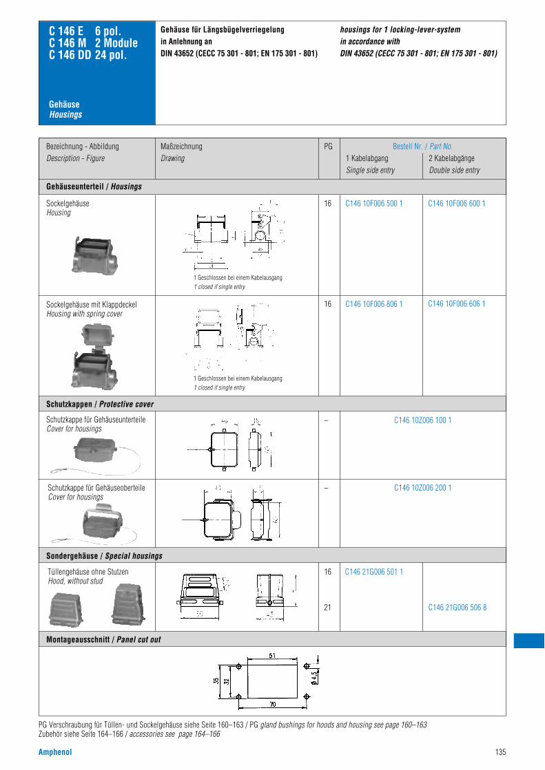
Amphenol 135
Gehäuseunterteil / Housings
Bezeichnung - AbbildungDescription - Figure
MaßzeichnungDrawing
PG Bestell Nr. / Part No.1 Kabelabgang 2 KabelabgängeSingle side entry Double side entry
SockelgehäuseHousing
16 C146 10F006 600 1C146 10F006 500 1
Sockelgehäuse mit KlappdeckelHousing with spring cover
16 C146 10F006 606 1C146 10F006 806 1
–
–
16
21
C146 10Z006 100 1
C146 10Z006 200 1
C146 21G006 501 1
C146 21G006 506 8
Schutzkappe für GehäuseunterteileCover for housings
C 146 E 6 pol.C 146 M 2 ModuleC 146 DD 24 pol.
Schutzkappen / Protective cover
Montageausschnitt / Panel cut out
Sondergehäuse / Special housings
Gehäuse für Längsbügelverriegelung in Anlehnung anDIN 43652 (CECC 75 301 - 801; EN 175 301 - 801)
housings for 1 locking-lever-system in accordance withDIN 43652 (CECC 75 301 - 801; EN 175 301 - 801)
PG Verschraubung für Tüllen- und Sockelgehäuse siehe Seite 160–163 / PG gland bushings for hoods and housing see page 160–163Zubehör siehe Seite 164–166 / accessories see page 164–166
Tüllengehäuse ohne StutzenHood, without stud
1 Geschlossen bei einem Kabelausgang1 closed if single entry
1 Geschlossen bei einem Kabelausgang1 closed if single entry
GehäuseHousings
Schutzkappe für GehäuseoberteileCover for housings
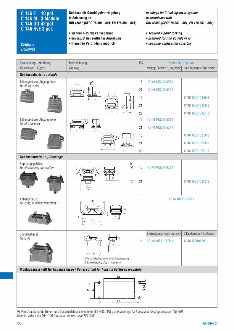
136 Amphenol
Gehäuseoberteile / Hoods
Bezeichnung - AbbildungDescription - Figure
MaßzeichnungDrawing
PG Bestell Nr. / Part No.Niedrige Bauform / Low profile Hohe Bauform / High profile
16
21
16
21
29
16
21
16
21
29
C146 10G010 600 1
C146 10G010 601 1
C146 10G010 500 1
C146 10G010 501 1
C146 10G010 650 8
C146 10G010 600 8
C146 10G010 601 8
C146 10G010 550 8
C146 10G010 500 8
C146 10G010 501 8
C 146 E 10 pol.C 146 M 3 ModuleC 146 DD 42 pol.C 146 HvE 3 pol.
Gehäuseunterteile / Housings
Montageausschnitt für Anbaugehäuse / Panel cut out for housing bulkhead mounting
16
21
h51
70
–
C146 10G010 802 1
C146 10G010 802 8
Tüllengehäuse, Abgang SeiteHood, side entry
C146 10F010 000 1
KupplungsgehäuseHood, coupling application
Anbaugehäuse 1)
Housing, bulkhead mounting 1)
16 C146 10F010 500 1
1 Kabelabgang / single side entry
C146 10F010 600 1
2 Kabelabgänge / 2 side entrySockelgehäuseHousing
Gehäuse für Querbügelverriegelung in Anlehnung an DIN 43652 (CECC 75 301 - 801; EN 175 301 - 801)
• sichere 4-Punkt Verriegelung• bevorzugt bei seitlicher Anreihung• fliegende Verbindung möglich
housings for 2 locking-lever-system in accordance withDIN 43652 (CECC 75 301 - 801; EN 175 301 - 801)
• secured 4 point locking• prefered for line up sideways• coupling application possibleGehäuse
Housings
PG Verschraubung für Tüllen- und Sockelgehäuse siehe Seite 160–163 / PG gland bushings for hoods and housing see page 160–163Zubehör siehe Seite 164–166 / accessories see page 164–166
Tüllengehäuse, Abgang obenHood, top entry
1.) Verschlußschraube bei einem Kabelausgang1.) Screwed sealing plug if single entry
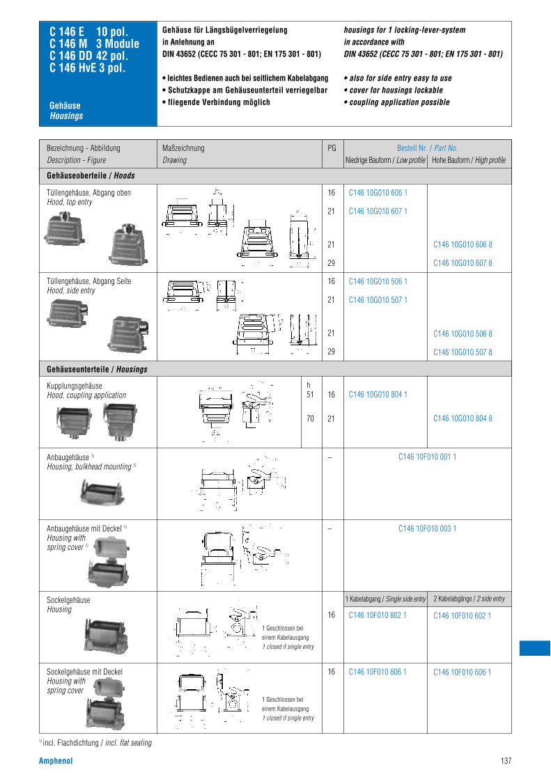
Amphenol 137
Gehäuseoberteile / Hoods
Bezeichnung - AbbildungDescription - Figure
MaßzeichnungDrawing
PG Bestell Nr. / Part No.Niedrige Bauform / Low profile Hohe Bauform / High profile
16
21
21
29
16
21
21
29
C146 10G010 606 1
C146 10G010 607 1
C146 10G010 506 1
C146 10G010 507 1
C146 10G010 606 8
C146 10G010 607 8
C146 10G010 506 8
C146 10G010 507 8
C 146 E 10 pol.C 146 M 3 ModuleC 146 DD 42 pol.C 146 HvE 3 pol.
Gehäuseunterteile / Housings
Tüllengehäuse, Abgang obenHood, top entry
16
21
h51
70
–
–
C146 10G010 804 1
C146 10G010 804 8
Tüllengehäuse, Abgang SeiteHood, side entry
C146 10F010 001 1
C146 10F010 003 1
Anbaugehäuse 1)
Housing, bulkhead mounting 1)
16 C146 10F010 802 1 C146 10F010 602 1
SockelgehäuseHousing
16 C146 10F010 806 1 C146 10F010 606 1
1) incl. Flachdichtung / incl. flat sealing
Gehäuse für Längsbügelverriegelung in Anlehnung anDIN 43652 (CECC 75 301 - 801; EN 175 301 - 801)
• leichtes Bedienen auch bei seitlichem Kabelabgang• Schutzkappe am Gehäuseunterteil verriegelbar• fliegende Verbindung möglich
housings for 1 locking-lever-system in accordance withDIN 43652 (CECC 75 301 - 801; EN 175 301 - 801)
• also for side entry easy to use• cover for housings lockable• coupling application possible
1 Kabelabgang / Single side entry 2 Kabelabgänge / 2 side entry
Sockelgehäuse mit DeckelHousing with spring cover
Anbaugehäuse mit Deckel 1)
Housing with spring cover 1)
1 Geschlossen bei einem Kabelausgang1 closed if single entry
1 Geschlossen bei einem Kabelausgang1 closed if single entry
KupplungsgehäuseHood, coupling application
GehäuseHousings
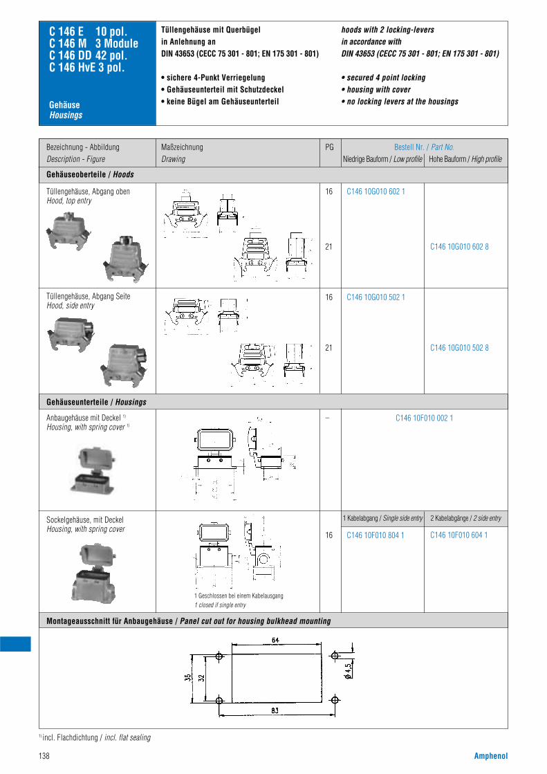
138 Amphenol
Gehäuseoberteile / Hoods
Bezeichnung - AbbildungDescription - Figure
MaßzeichnungDrawing
PG Bestell Nr. / Part No.Niedrige Bauform / Low profile Hohe Bauform / High profile
16
21
16
21
C146 10G010 602 1
C146 10G010 502 1
C146 10G010 602 8
C146 10G010 502 8
C146 10F010 002 1
C 146 E 10 pol.C 146 M 3 ModuleC 146 DD 42 pol.C 146 HvE 3 pol.
Gehäuseunterteile / Housings
Montageausschnitt für Anbaugehäuse / Panel cut out for housing bulkhead mounting
Tüllengehäuse, Abgang obenHood, top entry
–
Tüllengehäuse, Abgang SeiteHood, side entry
Anbaugehäuse mit Deckel 1)
Housing, with spring cover 1)
16 C146 10F010 804 1
1 Kabelabgang / Single side entry
C146 10F010 604 1
2 Kabelabgänge / 2 side entrySockelgehäuse, mit DeckelHousing, with spring cover
1) incl. Flachdichtung / incl. flat sealing
Tüllengehäuse mit Querbügelin Anlehnung anDIN 43653 (CECC 75 301 - 801; EN 175 301 - 801)
• sichere 4-Punkt Verriegelung• Gehäuseunterteil mit Schutzdeckel• keine Bügel am Gehäuseunterteil
hoods with 2 locking-levers in accordance withDIN 43653 (CECC 75 301 - 801; EN 175 301 - 801)
• secured 4 point locking• housing with cover• no locking levers at the housings
1 Geschlossen bei einem Kabelausgang1 closed if single entry
GehäuseHousings
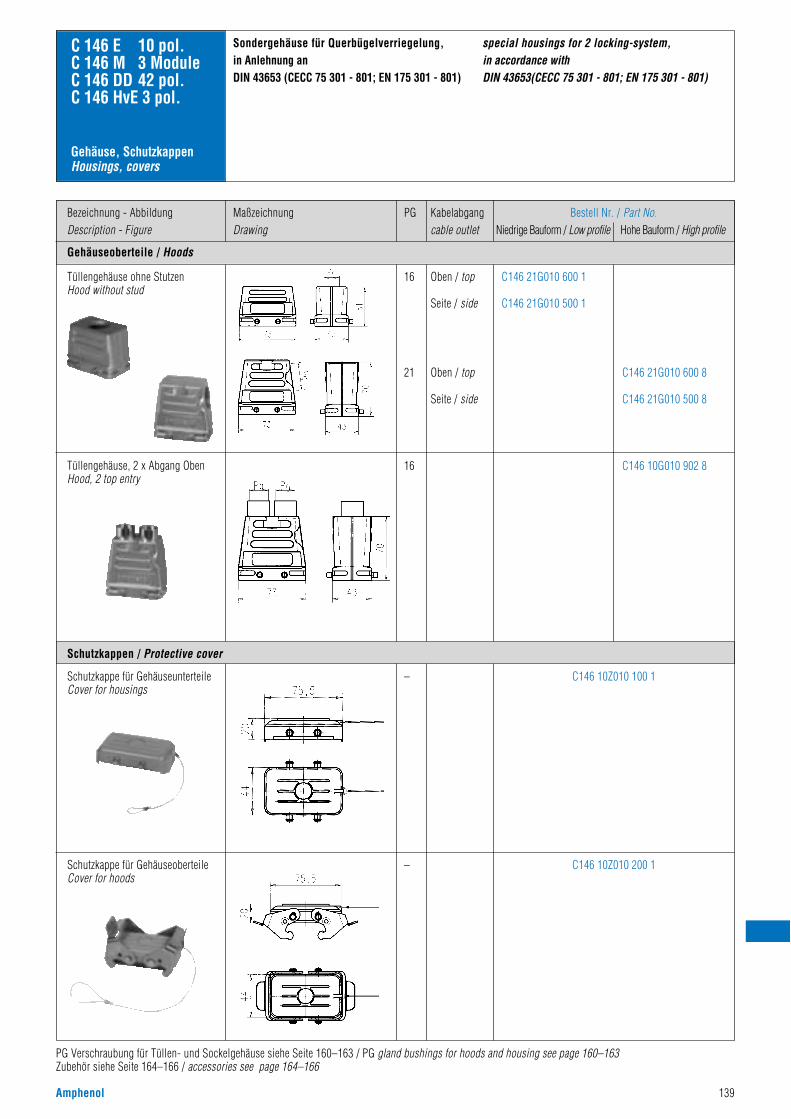
Amphenol 139
Gehäuseoberteile / Hoods
Bezeichnung - AbbildungDescription - Figure
MaßzeichnungDrawing
PG Kabelabgangcable outlet
Bestell Nr. / Part No.Niedrige Bauform / Low profile Hohe Bauform / High profile
C146 21G010 600 1
C146 21G010 500 1
C146 10Z010 100 1
C146 10Z010 200 1
C146 21G010 600 8
C146 21G010 500 8
C146 10G010 902 8
C 146 E 10 pol.C 146 M 3 ModuleC 146 DD 42 pol.C 146 HvE 3 pol.
Tüllengehäuse ohne StutzenHood without stud
Tüllengehäuse, 2 x Abgang ObenHood, 2 top entry
Schutzkappe für GehäuseunterteileCover for housings
Schutzkappe für GehäuseoberteileCover for hoods
Sondergehäuse für Querbügelverriegelung, in Anlehnung anDIN 43653 (CECC 75 301 - 801; EN 175 301 - 801)
PG Verschraubung für Tüllen- und Sockelgehäuse siehe Seite 160–163 / PG gland bushings for hoods and housing see page 160–163Zubehör siehe Seite 164–166 / accessories see page 164–166
Schutzkappen / Protective cover
special housings for 2 locking-system, in accordance withDIN 43653(CECC 75 301 - 801; EN 175 301 - 801)
16
21
Oben / top
Seite / side
Oben / top
Seite / side
16
–
–
Gehäuse, SchutzkappenHousings, covers
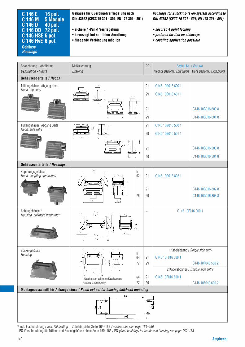
140 Amphenol
Gehäuseoberteile / Hoods
Bezeichnung - AbbildungDescription - Figure
MaßzeichnungDrawing
PG Bestell Nr. / Part No.Niedrige Bauform / Low profile Hohe Bauform / High profile
21
29
21
29
21
29
21
29
C146 10G016 600 1
C146 10G016 601 1
C146 10G016 500 1
C146 10G016 501 1
C146 10G016 600 8
C146 10G016 601 8
C146 10G016 500 8
C146 10G016 501 8
C 146 E 16 pol.C 146 M 5 ModuleC 146 D 40 pol.C 146 DD 72 pol.C 146 HSE 6 pol.C 146 HvE 6 pol.
Gehäuseunterteile / Housings
Montageausschnitt für Anbaugehäuse / Panel cut out for housing bulkhead mounting
Tüllengehäuse, Abgang obenHood, top entry
21
21
29
h62
76
–
C146 10G016 802 1
C146 10G016 802 8
C146 10G016 803 8
Tüllengehäuse, Abgang SeiteHood, side entry
C146 10F016 000 1
KupplungsgehäuseHood, coupling application
Anbaugehäuse 1)
Housing, bulkhead mounting 1)
21
29
h64
77
64
77
21
29
C146 10F016 500 1
C146 10F016 600 1
1 Kabelabgang / Single side entry
C146 10F040 500 2
C146 10F040 600 2
2 Kabelabgänge / Double side entry
SockelgehäuseHousing
Gehäuse für Querbügelverriegelung nachDIN 43652 (CECC 75 301 - 801; EN 175 301 - 801)
• sichere 4-Punkt Verriegelung• bevorzugt bei seitlicher Anreihung• fliegende Verbindung möglich
1) incl. Flachdichtung / incl. flat sealing Zubehör siehe Seite 164–166 / accessories see page 164–166PG Verschraubung für Tüllen- und Sockelgehäuse siehe Seite 160–163 / PG gland bushings for hoods and housing see page 160–163
housings for 2 locking-lever-system according toDIN 43652 (CECC 75 301 - 801; EN 175 301 - 801)
• secured 4 point locking• prefered for line up sideways• coupling application possible
1 Geschlossen bei einem Kabelausgang1 closed if single entry
GehäuseHousings
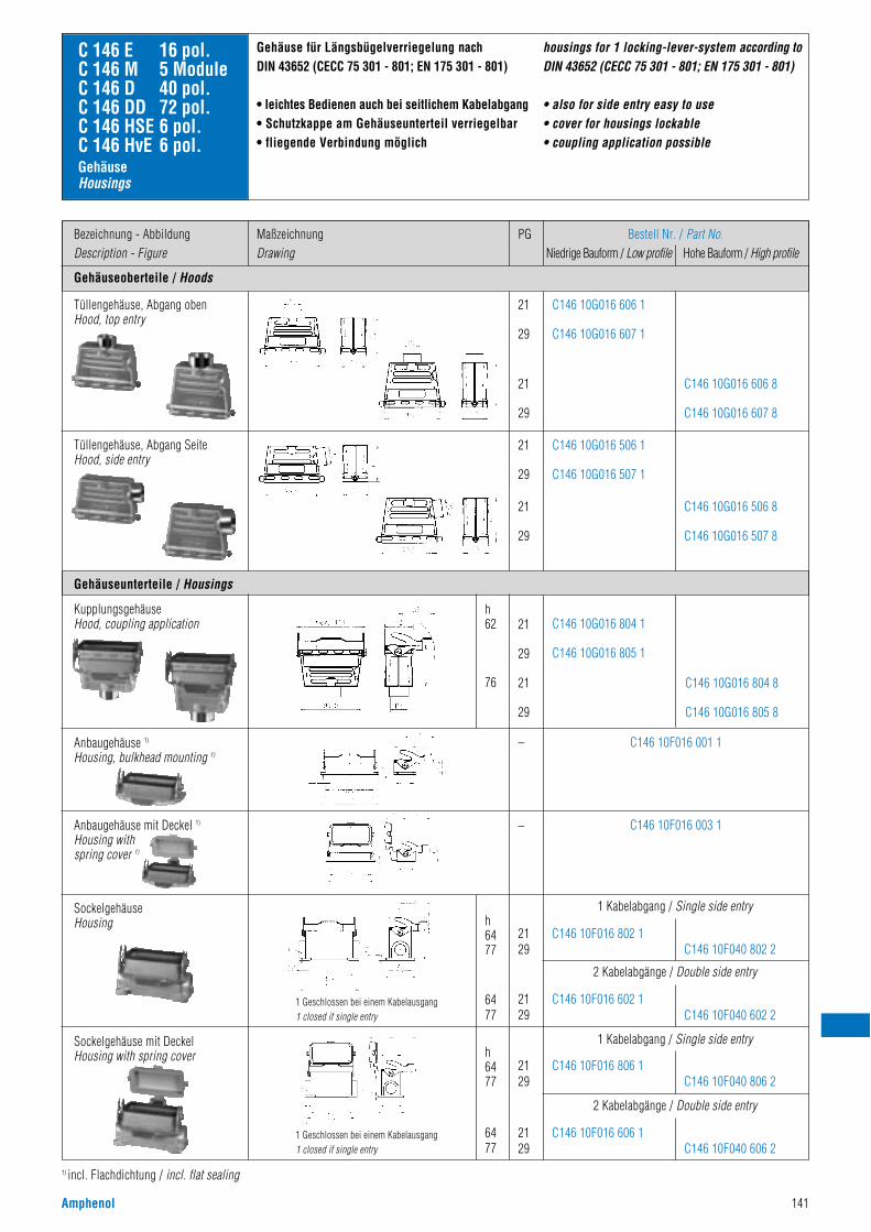
Amphenol 141
Gehäuseoberteile / Hoods
Bezeichnung - AbbildungDescription - Figure
MaßzeichnungDrawing
PG Bestell Nr. / Part No.Niedrige Bauform / Low profile Hohe Bauform / High profile
21
29
21
29
21
29
21
29
C146 10G016 606 1
C146 10G016 607 1
C146 10G016 506 1
C146 10G016 507 1
C146 10G016 606 8
C146 10G016 607 8
C146 10G016 506 8
C146 10G016 507 8
C 146 E 16 pol.C 146 M 5 ModuleC 146 D 40 pol.C 146 DD 72 pol.C 146 HSE 6 pol.C 146 HvE 6 pol.
Gehäuseunterteile / Housings
Tüllengehäuse, Abgang obenHood, top entry
21
29
21
29
h62
76
–
–
C146 10G016 804 1
C146 10G016 805 1
C146 10G016 804 8
C146 10G016 805 8
Tüllengehäuse, Abgang SeiteHood, side entry
KupplungsgehäuseHood, coupling application
C146 10F016 001 1
C146 10F016 003 1
Anbaugehäuse 1)
Housing, bulkhead mounting 1)
2129
h6477
6477
h6477
6477
1 Kabelabgang / Single side entry
1 Kabelabgang / Single side entry
2 Kabelabgänge / Double side entry
2 Kabelabgänge / Double side entry
C146 10F040 802 2C146 10F016 802 1
2129 C146 10F040 602 2
C146 10F016 602 1
2129 C146 10F040 806 2
C146 10F016 806 1
2129 C146 10F040 606 2
C146 10F016 606 1
SockelgehäuseHousing
Sockelgehäuse mit DeckelHousing with spring cover
1) incl. Flachdichtung / incl. flat sealing
Gehäuse für Längsbügelverriegelung nachDIN 43652 (CECC 75 301 - 801; EN 175 301 - 801)
• leichtes Bedienen auch bei seitlichem Kabelabgang• Schutzkappe am Gehäuseunterteil verriegelbar• fliegende Verbindung möglich
housings for 1 locking-lever-system according toDIN 43652 (CECC 75 301 - 801; EN 175 301 - 801)
• also for side entry easy to use• cover for housings lockable• coupling application possible
1 Geschlossen bei einem Kabelausgang1 closed if single entry
1 Geschlossen bei einem Kabelausgang1 closed if single entry
GehäuseHousings
Anbaugehäuse mit Deckel 1)
Housing with spring cover 1)
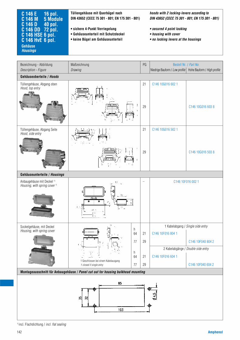
142 Amphenol
Gehäuseoberteile / Hoods
Bezeichnung - AbbildungDescription - Figure
MaßzeichnungDrawing
PG Bestell Nr. / Part No.Niedrige Bauform / Low profile Hohe Bauform / High profile
21
29
21
29
C146 10G016 602 1
C146 10G016 502 1
C146 10G016 603 8
C146 10G016 503 8
C146 10F016 002 1
C 146 E 16 pol.C 146 M 5 ModuleC 146 D 40 pol.C 146 DD 72 pol.C 146 HSE 6 pol.C 146 HvE 6 pol.
Gehäuseunterteile / Housings
Montageausschnitt für Anbaugehäuse / Panel cut out for housing bulkhead mounting
Tüllengehäuse, Abgang obenHood, top entry
–
Tüllengehäuse, Abgang SeiteHood, side entry
Anbaugehäuse mit Deckel 1)
Housing, with spring cover 1)
Sockelgehäuse, mit DeckelHousing, with spring cover
1) incl. Flachdichtung / incl. flat sealing
Tüllengehäuse mit Querbügel nachDIN 43652 (CECC 75 301 - 801; EN 175 301 - 801)
• sichere 4-Punkt Verriegelung• Gehäuseunterteil mit Schutzdeckel• keine Bügel am Gehäuseunterteil
21
29
h64
77
h64
77
C146 10F040 804 2
C146 10F016 804 1
21
29 C146 10F040 604 2
C146 10F016 604 1
2 Kabelabgänge / Double side entry
1 Kabelabgang / Single side entry
hoods with 2 locking-levers according to DIN 43652 (CECC 75 301 - 801; EN 175 301 - 801)
• secured 4 point locking• housing with cover• no locking levers at the housings
1 Geschlossen bei einem Kabelausgang1 closed if single entry
GehäuseHousings
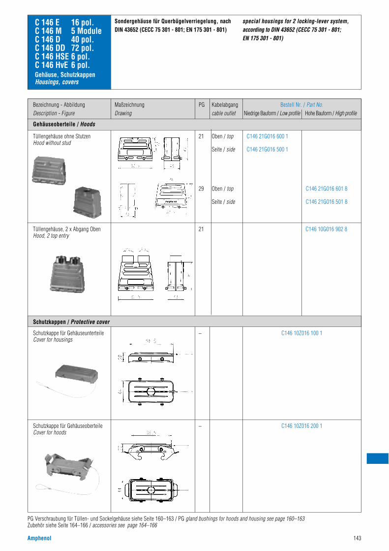
Amphenol 143
Gehäuseoberteile / Hoods
Bezeichnung - AbbildungDescription - Figure
MaßzeichnungDrawing
Bestell Nr. / Part No.Niedrige Bauform / Low profile Hohe Bauform / High profile
C146 21G016 600 1
C146 21G016 500 1
C146 10Z016 100 1
C146 10Z016 200 1
C146 21G016 601 8
C146 21G016 501 8
C146 10G016 902 8
C 146 E 16 pol.C 146 M 5 ModuleC 146 D 40 pol.C 146 DD 72 pol.C 146 HSE 6 pol.C 146 HvE 6 pol.
Tüllengehäuse ohne StutzenHood without stud
Tüllengehäuse, 2 x Abgang ObenHood, 2 top entry
Schutzkappe für GehäuseunterteileCover for housings
Schutzkappe für GehäuseoberteileCover for hoods
Sondergehäuse für Querbügelverriegelung, nachDIN 43652 (CECC 75 301 - 801; EN 175 301 - 801)
Schutzkappen / Protective cover
special housings for 2 locking-lever system,according to DIN 43652 (CECC 75 301 - 801; EN 175 301 - 801)
21
29
21
–
–
PG Verschraubung für Tüllen- und Sockelgehäuse siehe Seite 160–163 / PG gland bushings for hoods and housing see page 160–163Zubehör siehe Seite 164–166 / accessories see page 164–166
Gehäuse, SchutzkappenHousings, covers
PG Kabelabgangcable outlet
Oben / top
Seite / side
Oben / top
Seite / side
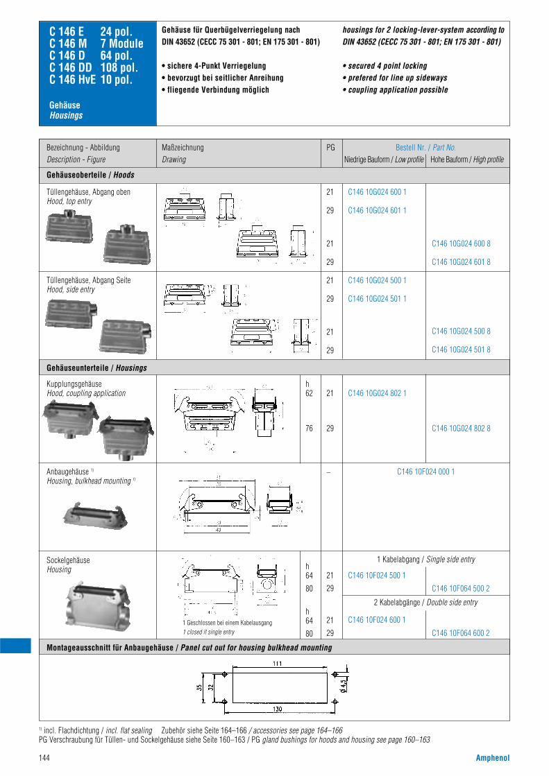
144 Amphenol
Gehäuseoberteile / Hoods
Bezeichnung - AbbildungDescription - Figure
MaßzeichnungDrawing
PG Bestell Nr. / Part No.Niedrige Bauform / Low profile Hohe Bauform / High profile
21
29
21
29
21
29
21
29
C146 10G024 600 1
C146 10G024 601 1
C146 10G024 500 1
C146 10G024 501 1
C146 10G024 600 8
C146 10G024 601 8
C146 10G024 500 8
C146 10G024 501 8
C 146 E 24 pol.C 146 M 7 ModuleC 146 D 64 pol.C 146 DD 108 pol.C 146 HvE 10 pol.
Gehäuseunterteile / Housings
Montageausschnitt für Anbaugehäuse / Panel cut out for housing bulkhead mounting
Tüllengehäuse, Abgang obenHood, top entry
21
29
h62
76
–
C146 10G024 802 1
C146 10G024 802 8
Tüllengehäuse, Abgang SeiteHood, side entry
C146 10F024 000 1
KupplungsgehäuseHood, coupling application
Anbaugehäuse 1)
Housing, bulkhead mounting 1)
21
29
h64
80
h64
80
21
29
C146 10F024 500 1
C146 10F024 600 1
1 Kabelabgang / Single side entry
C146 10F064 500 2
C146 10F064 600 2
2 Kabelabgänge / Double side entry
SockelgehäuseHousing
Gehäuse für Querbügelverriegelung nachDIN 43652 (CECC 75 301 - 801; EN 175 301 - 801)
• sichere 4-Punkt Verriegelung• bevorzugt bei seitlicher Anreihung• fliegende Verbindung möglich
1) incl. Flachdichtung / incl. flat sealing Zubehör siehe Seite 164–166 / accessories see page 164–166PG Verschraubung für Tüllen- und Sockelgehäuse siehe Seite 160–163 / PG gland bushings for hoods and housing see page 160–163
housings for 2 locking-lever-system according toDIN 43652 (CECC 75 301 - 801; EN 175 301 - 801)
• secured 4 point locking• prefered for line up sideways• coupling application possible
1 Geschlossen bei einem Kabelausgang1 closed if single entry
GehäuseHousings
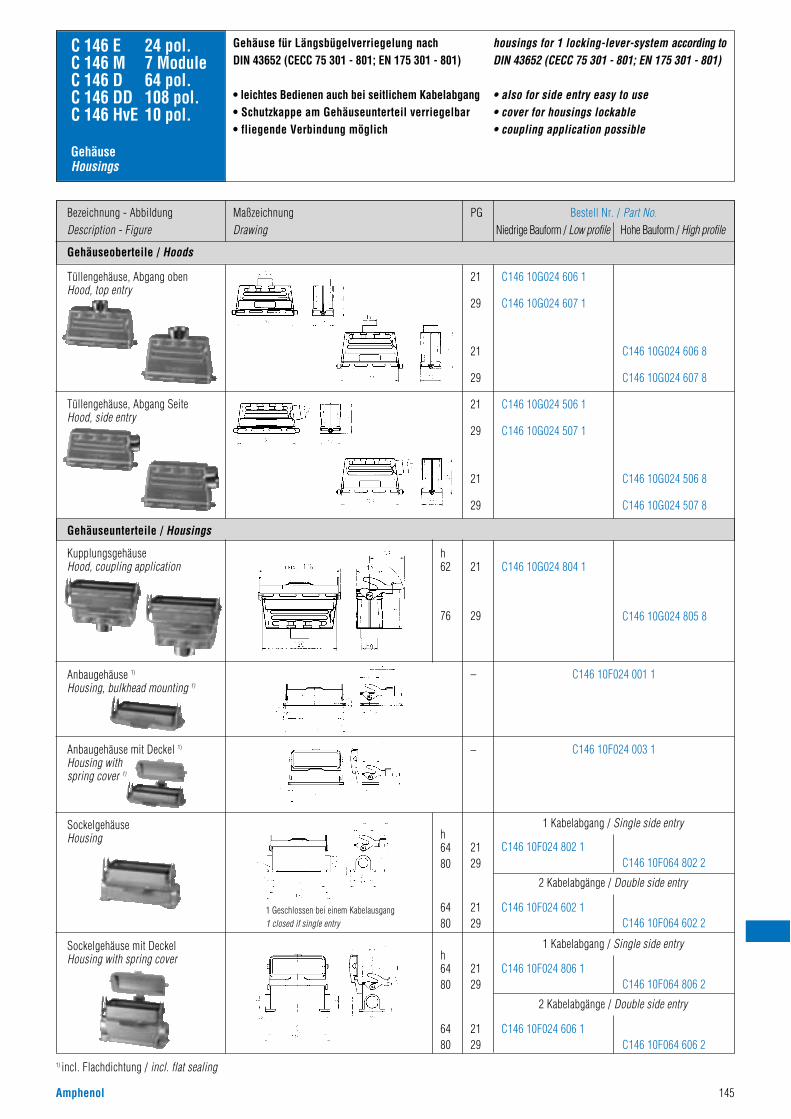
Amphenol 145
Gehäuseoberteile / Hoods
Bezeichnung - AbbildungDescription - Figure
MaßzeichnungDrawing
PG Bestell Nr. / Part No.Niedrige Bauform / Low profile Hohe Bauform / High profile
21
29
21
29
21
29
21
29
C146 10G024 606 1
C146 10G024 607 1
C146 10G024 506 1
C146 10G024 507 1
C146 10G024 606 8
C146 10G024 607 8
C146 10G024 506 8
C146 10G024 507 8
C 146 E 24 pol.C 146 M 7 ModuleC 146 D 64 pol.C 146 DD 108 pol.C 146 HvE 10 pol.
Gehäuseunterteile / Housings
Tüllengehäuse, Abgang obenHood, top entry
21
29
h62
76
–
–
C146 10G024 804 1
C146 10G024 805 8
Tüllengehäuse, Abgang SeiteHood, side entry
KupplungsgehäuseHood, coupling application
C146 10F024 001 1
C146 10F024 003 1
Anbaugehäuse 1)
Housing, bulkhead mounting 1)
2129
h6480
6480
h6480
6480
1 Kabelabgang / Single side entry
1 Kabelabgang / Single side entry
2 Kabelabgänge / Double side entry
2 Kabelabgänge / Double side entry
C146 10F064 802 2C146 10F024 802 1
2129 C146 10F064 602 2
C146 10F024 602 1
2129 C146 10F064 806 2
C146 10F024 806 1
2129 C146 10F064 606 2
C146 10F024 606 1
SockelgehäuseHousing
Sockelgehäuse mit DeckelHousing with spring cover
1) incl. Flachdichtung / incl. flat sealing
Gehäuse für Längsbügelverriegelung nachDIN 43652 (CECC 75 301 - 801; EN 175 301 - 801)
• leichtes Bedienen auch bei seitlichem Kabelabgang• Schutzkappe am Gehäuseunterteil verriegelbar• fliegende Verbindung möglich
housings for 1 locking-lever-system according toDIN 43652 (CECC 75 301 - 801; EN 175 301 - 801)
• also for side entry easy to use• cover for housings lockable• coupling application possible
Anbaugehäuse mit Deckel 1)
Housing with spring cover 1)
1 Geschlossen bei einem Kabelausgang1 closed if single entry
GehäuseHousings
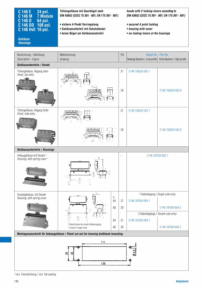
146 Amphenol
Gehäuseoberteile / Hoods
Bezeichnung - AbbildungDescription - Figure
MaßzeichnungDrawing
PG Bestell Nr. / Part No.Niedrige Bauform / Low profile Hohe Bauform / High profile
21
29
21
29
C146 10G024 602 1
C146 10G024 502 1
C146 10G024 603 8
C146 10G024 503 8
C146 10F024 002 1
C 146 E 24 pol.C 146 M 7 ModuleC 146 D 64 pol.C 146 DD 108 pol.C 146 HvE 10 pol.
Gehäuseunterteile / Housings
Montageausschnitt für Anbaugehäuse / Panel cut out for housing bulkhead mounting
Tüllengehäuse, Abgang obenHood, top entry
–
Tüllengehäuse, Abgang SeiteHood, side entry
Anbaugehäuse mit Deckel 1)
Housing, with spring cover 1)
Sockelgehäuse, mit DeckelHousing, with spring cover
1) incl. Flachdichtung / incl. flat sealing
Tüllengehäuse mit Querbügel nachDIN 43652 (CECC 75 301 - 801; EN 175 301 - 801)
• sichere 4-Punkt Verriegelung• Gehäuseunterteil mit Schutzdeckel• keine Bügel am Gehäuseunterteil
21
29
h64
80
64
80
C146 10F064 804 2
C146 10F024 804 1
21
29 C146 10F064 604 2
C146 10F024 604 1
2 Kabelabgänge / Double side entry
1 Kabelabgang / Single side entry
hoods with 2 locking-levers according to DIN 43652 (CECC 75 301 - 801; EN 175 301 - 801)
• secured 4 point locking• housing with cover• no locking levers at the housings
1 Geschlossen bei einem Kabelausgang1 closed if single entry
GehäuseHousings
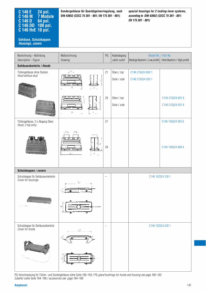
Amphenol 147
Gehäuseoberteile / Hoods
Bezeichnung - AbbildungDescription - Figure
MaßzeichnungDrawing
Bestell Nr. / Part No.Niedrige Bauform / Low profile Hohe Bauform / High profile
C146 21G024 600 1
C146 21G024 500 1
C146 10G024 903 8
C146 10G024 908 8
C146 10Z024 100 1
C146 10Z024 200 1
C146 21G024 601 8
C146 21G024 501 8
C 146 E 24 pol.C 146 M 7 ModuleC 146 D 64 pol.C 146 DD 108 pol.C 146 HvE 10 pol.
Tüllengehäuse ohne StutzenHood without stud
Schutzkappe für GehäuseunterteileCover for housings
Schutzkappe für GehäuseoberteileCover for hoods
Sondergehäuse für Querbügelverriegelung, nachDIN 43652 (CECC 75 301 - 801; EN 175 301 - 801)
PG Verschraubung für Tüllen- und Sockelgehäuse siehe Seite 160–163 / PG gland bushings for hoods and housing see page 160–163Zubehör siehe Seite 164–166 / accessories see page 164–166
Schutzkappen / covers
special housings for 2 locking-lever systems, according to DIN 43652 (CECC 75 301 - 801; EN 175 301 - 801)
21
29
21
29
–
–
Tüllengehäuse, 2 x Abgang ObenHood, 2 top entry
Gehäuse, SchutzkappenHousings, covers
PG Kabelabgangcable outlet
Oben / top
Seite / side
Oben / top
Seite / side
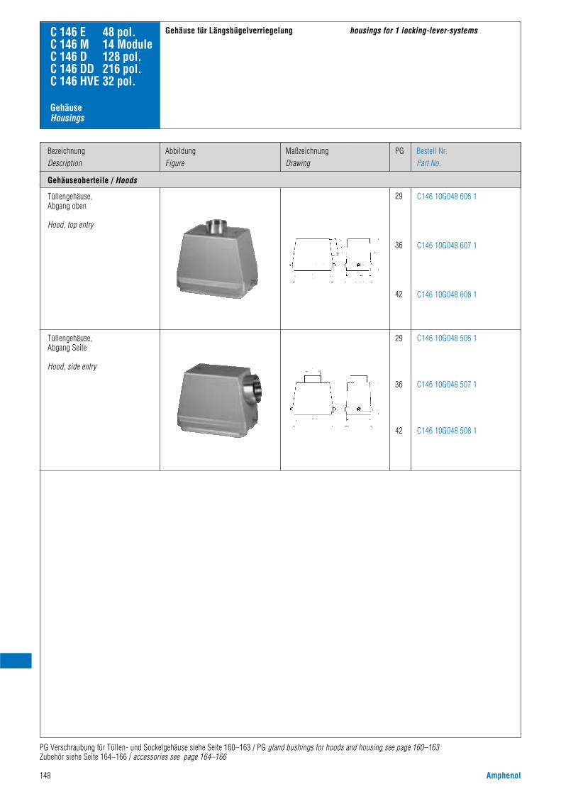
148 Amphenol
Tüllengehäuse,Abgang oben
Hood, top entry
29
36
42
C146 10G048 606 1
C146 10G048 607 1
C146 10G048 608 1
Tüllengehäuse,Abgang Seite
Hood, side entry
29
36
42
C146 10G048 506 1
C146 10G048 507 1
C146 10G048 508 1
C 146 E 48 pol.C 146 M 14 ModuleC 146 D 128 pol.C 146 DD 216 pol.C 146 HVE 32 pol.
Gehäuseoberteile / Hoods
BezeichnungDescription
AbbildungFigure
PGMaßzeichnungDrawing
Bestell Nr.Part No.
PG Verschraubung für Tüllen- und Sockelgehäuse siehe Seite 160–163 / PG gland bushings for hoods and housing see page 160–163Zubehör siehe Seite 164–166 / accessories see page 164–166
Gehäuse für Längsbügelverriegelung housings for 1 locking-lever-systems
GehäuseHousings
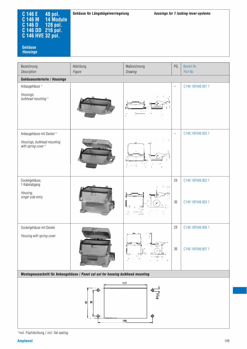
Amphenol 149
Anbaugehäuse 1)
Housings,bulkhead mounting 1)
Anbaugehäuse mit Deckel 1)
Housings, bulkhead mountingwith spring cover 1)
Sockelgehäuse,1 Kabelabgang
Housing,singel side entry
Sockelgehäuse mit Deckel
Housing with spring cover
–
–
29
36
29
36
C146 10F048 001 1
C146 10F048 003 1
C146 10F048 802 1
C146 10F048 803 1
C146 10F048 806 1
C146 10F048 807 1
C 146 E 48 pol.C 146 M 14 ModuleC 146 D 128 pol.C 146 DD 216 pol.C 146 HVE 32 pol.
Gehäuseunterteile / Housings
BezeichnungDescription
AbbildungFigure
PGMaßzeichnungDrawing
Bestell Nr.Part No.
1) incl. Flachdichtung / incl. flat sealing
Gehäuse für Längsbügelverriegelung housings for 1 locking-lever-systems
Montageausschnitt für Anbaugehäuse / Panel cut out for housing bulkhead mounting
GehäuseHousings
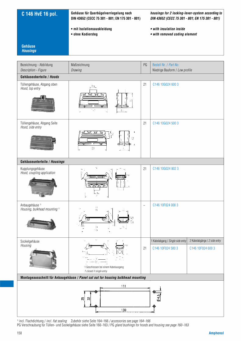
150 Amphenol
Gehäuseoberteile / Hoods
Bezeichnung - AbbildungDescription - Figure
MaßzeichnungDrawing
PG Bestell Nr. / Part No.Niedrige Bauform / Low profile
21
21
C146 10G024 600 3
C146 10G024 500 3
C 146 HvE 16 pol.
Gehäuseunterteile / Housings
Montageausschnitt für Anbaugehäuse / Panel cut out for housing bulkhead mounting
Tüllengehäuse, Abgang obenHood, top entry
21
–
C146 10G024 802 3
Tüllengehäuse, Abgang SeiteHood, side entry
C146 10F024 000 3
KupplungsgehäuseHood, coupling application
Anbaugehäuse 1)
Housing, bulkhead mounting 1)
21 C146 10F024 500 3
1 Kabelabgang / Single side entry
C146 10F024 600 3
2 Kabelabgänge / 2 side entrySockelgehäuseHousing
Gehäuse für Querbügelverriegelung nachDIN 43652 (CECC 75 301 - 801; EN 175 301 - 801)
• mit Isolationsauskleidung• ohne Kodiersteg
housings for 2 locking-lever-system according toDIN 43652 (CECC 75 301 - 801; EN 175 301 - 801)
• with insulation inside• with removed coding element
GehäuseHousings
1) incl. Flachdichtung / incl. flat sealing Zubehör siehe Seite 164–166 / accessories see page 164–166PG Verschraubung für Tüllen- und Sockelgehäuse siehe Seite 160–163 / PG gland bushings for hoods and housing see page 160–163
1 Geschlossen bei einem Kabelausgang1 closed if single entry
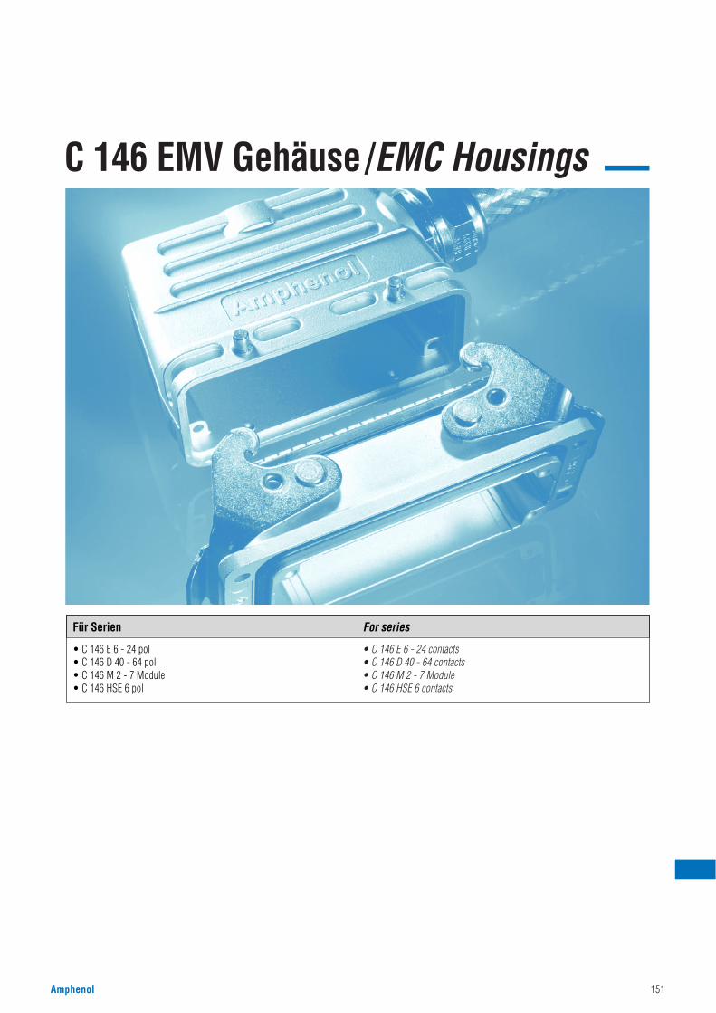
C 146 EMV Gehäuse/EMC Housings
Amphenol 151
• C 146 E 6 - 24 pol• C 146 D 40 - 64 pol• C 146 M 2 - 7 Module• C 146 HSE 6 pol
• C 146 E 6 - 24 contacts• C 146 D 40 - 64 contacts• C 146 M 2 - 7 Module• C 146 HSE 6 contacts
Für Serien For series
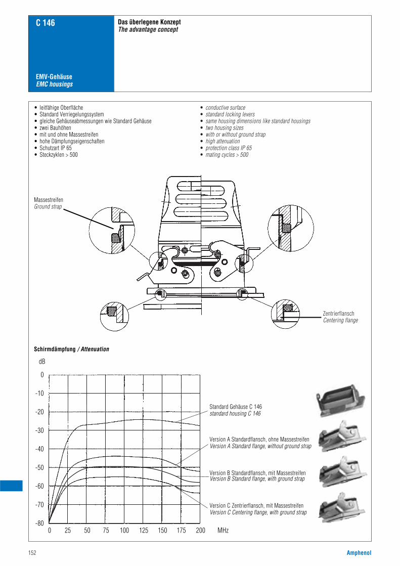
152 Amphenol
Das überlegene KonzeptThe advantage concept
C 146
• leitfähige Oberfläche• Standard Verriegelungssystem• gleiche Gehäuseabmessungen wie Standard Gehäuse• zwei Bauhöhen• mit und ohne Massestreifen• hohe Dämpfungseigenschaften• Schutzart IP 65• Steckzyklen > 500
MassestreifenGround strap
ZentrierflanschCentering flange
• conductive surface• standard locking levers• same housing dimensions like standard housings• two housing sizes• with or without ground strap• high attenuation• protection class IP 65• mating cycles > 500
0
-10
-20
-30
-40
-50
-60
-70
-800 25 50 75 100 125 150 175 200 MHz
dB
Schirmdämpfung / Attenuation
Standard Gehäuse C 146standard housing C 146
EMV-GehäuseEMC housings
Version A Standardflansch, ohne MassestreifenVersion A Standard flange, without ground strap
Version B Standardflansch, mit MassestreifenVersion B Standard flange, with ground strap
Version C Zentrierflansch, mit MassestreifenVersion C Centering flange, with ground strap
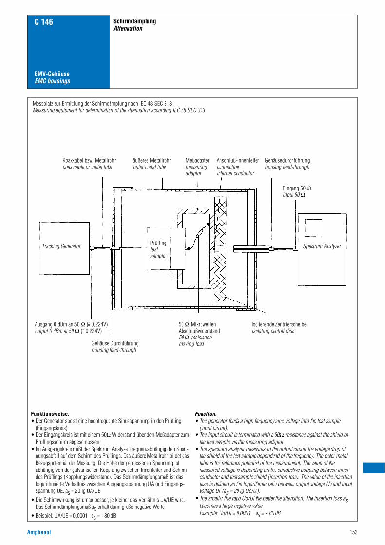
Amphenol 153
SchirmdämpfungAttenuation
C 146
EMV-GehäuseEMC housings
Function:• The generator feeds a high frequency sine voltage into the test sample
(input circuit).• The input circuit is terminated with a 50Ω resistance against the shield of
the test sample via the measuring adaptor.• The spectrum analyzer measures in the output circuit the voltage drop of
the shield of the test sample dependend of the frequency. The outer metaltube is the reference potential of the measurement. The value of the measured voltage is depending on the conductive coupling between innerconductor and test sample shield (insertion loss). The value of the insertionloss is defined as the logarithmic ratio between output voltage Uo and inputvoltage Ui (as = 20 lg Uo/Ui).
• The smaller the ratio Uo/Ui the better the attenution. The insertion loss asbecomes a large negative value.Example: Uo/Ui = 0,0001 as = - 80 dB
Funktionsweise:• Der Generator speist eine hochfrequente Sinusspannung in den Prüfling
(Eingangskreis).• Der Eingangskreis ist mit einem 50Ω Widerstand über den Meßadapter zum
Prüflingsschirm abgeschlossen.• Im Ausgangskreis mißt der Spektrum Analyzer frequenzabhängig den Span-
nungsabfall auf dem Schirm des Prüflings. Das äußere Metallrohr bildet dasBezugspotential der Messung. Die Höhe der gemessenen Spannung istabhängig von der galvanischen Kopplung zwischen Innenleiter und Schirmdes Prüflings (Kopplungswiderstand). Das Schirmdämpfungsmaß ist daslogarithmierte Verhältnis zwischen Ausgangsspannung UA und Eingangs-spannung UE. as = 20 lg UA/UE.
• Die Schirmwirkung ist umso besser, je kleiner das Verhältnis UA/UE wird.Das Schirmdämpfungsmaß as erhält dann große negative Werte.
• Beispiel: UA/UE = 0,0001 as = - 80 dB
Messplatz zur Ermittlung der Schirmdämpfung nach IEC 48 SEC 313Measuring equipment for determination of the attenuation according IEC 48 SEC 313
Koaxkabel bzw. Metallrohrcoax cable or metal tube
Gehäuse Durchführunghousing feed-through
50 Ω MikrowellenAbschlußwiderstand50 Ω resistancemoving load
Isolierende Zentrierscheibeisolating central disc
Ausgang 0 dBm an 50 Ω (^= 0,224V)output 0 dBm at 50 Ω (^= 0,224V)
äußeres Metallrohrouter metal tube
Prüflingtestsample
Meßadaptermeasuringadaptor
Gehäusedurchführunghousing feed-through
Eingang 50 Ωinput 50 Ω
Spectrum AnalyzerTracking Generator
Anschluß-Innenleiterconnectioninternal conductor
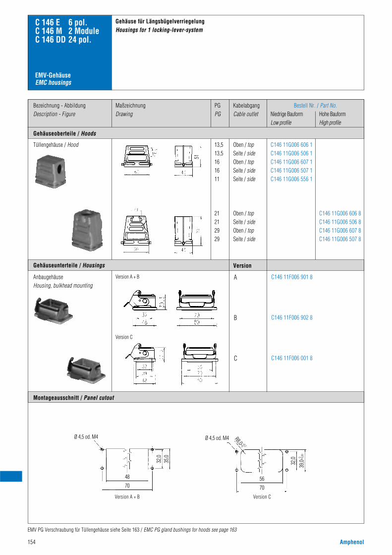
154 Amphenol
EMV-GehäuseEMC housings
Bezeichnung - AbbildungDescription - Figure
Gehäuseoberteile / Hoods
MaßzeichnungDrawing
PGPG
KabelabgangCable outlet
C146 11G006 606 8C146 11G006 506 8C146 11G006 607 8C146 11G006 507 8
C146 11G006 606 1C146 11G006 506 1C146 11G006 607 1C146 11G006 507 1C146 11G006 556 1
Tüllengehäuse / Hood
Bestell Nr. / Part No.Niedrige Bauform Hohe BauformLow profile High profile
Oben / topSeite / sideOben / topSeite / sideSeite / side
Oben / topSeite / sideOben / topSeite / side
13,513,5161611
21212929
Version
C146 11F006 901 8
C146 11F006 902 8
C146 11F006 001 8
A
B
C
AnbaugehäuseHousing, bulkhead mounting
Version C
Montageausschnitt / Panel cutout
Version A + B
Ø 4,5 od. M4
48
70
32,0
35,0
Version C
32,0
39,0-
0,20
0
R8,0-0+0,2
56
70
Ø 4,5 od. M4
Version A + B
C 146 E 6 pol.C 146 M 2 ModuleC 146 DD 24 pol.
Gehäuse für LängsbügelverriegelungHousings for 1 locking-lever-system
EMV PG Verschraubung für Tüllengehäuse siehe Seite 163 / EMC PG gland bushings for hoods see page 163
Gehäuseunterteile / Housings
51
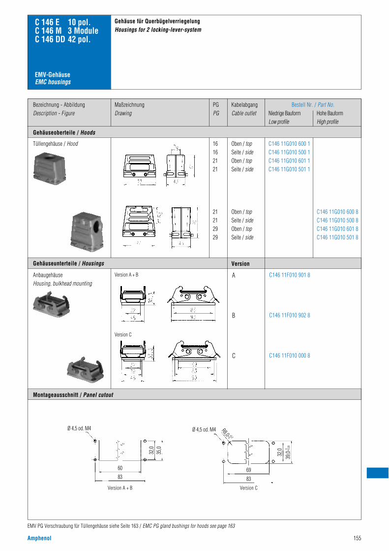
Amphenol 155
EMV-GehäuseEMC housings
Bezeichnung - AbbildungDescription - Figure
Gehäuseoberteile / Hoods
MaßzeichnungDrawing
PGPG
KabelabgangCable outlet
C146 11G010 600 8C146 11G010 500 8C146 11G010 601 8C146 11G010 501 8
C146 11G010 600 1C146 11G010 500 1C146 11G010 601 1C146 11G010 501 1
Tüllengehäuse / Hood
Bestell Nr. / Part No.Niedrige Bauform Hohe BauformLow profile High profile
Oben / topSeite / sideOben / topSeite / side
Oben / topSeite / sideOben / topSeite / side
16162121
21212929
Version
C146 11F010 901 8
C146 11F010 902 8
C146 11F010 000 8
A
B
C
AnbaugehäuseHousing, bulkhead mounting
Version C
Montageausschnitt / Panel cutout
Version A + B
C 146 E 10 pol.C 146 M 3 ModuleC 146 DD 42 pol.
Gehäuse für QuerbügelverriegelungHousings for 2 locking-lever-system
EMV PG Verschraubung für Tüllengehäuse siehe Seite 163 / EMC PG gland bushings for hoods see page 163
Version A + B Version C
Ø 4,5 od. M4
60
83
32,0
35,0
32,0
39,0-
0,20
0
R8,0-0+0,2
69
83
Ø 4,5 od. M4
Gehäuseunterteile / Housings
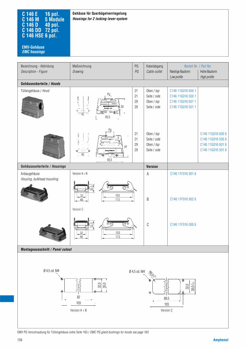
156 Amphenol
EMV-GehäuseEMC housings
Bezeichnung - AbbildungDescription - Figure
Gehäuseoberteile / Hoods
MaßzeichnungDrawing
PGPG
KabelabgangCable outlet
C146 11G016 600 8C146 11G016 500 8C146 11G016 601 8C146 11G016 501 8
C146 11G016 600 1C146 11G016 500 1C146 11G016 601 1C146 11G016 501 1
Tüllengehäuse / Hood
Bestell Nr. / Part No.Niedrige Bauform Hohe BauformLow profile High profile
Oben / topSeite / sideOben / topSeite / side
Oben / topSeite / sideOben / topSeite / side
21212929
21212929
Version
C146 11F016 901 8
C146 11F016 902 8
C146 11F016 000 8
A
B
C
AnbaugehäuseHousing, bulkhead mounting
Montageausschnitt / Panel cutout
Version A + B
C 146 E 16 pol.C 146 M 5 ModuleC 146 D 40 pol.C 146 DD 72 pol.C 146 HSE 6 pol.
Gehäuse für QuerbügelverriegelungHousings for 2 locking-lever-system
EMV PG Verschraubung für Tüllengehäuse siehe Seite 163 / EMC PG gland bushings for hoods see page 163
Version A + B Version C
Ø 4,5 od. M4
82
103
32,0
35,0
32,0
39,0-
0,20
0
R8,0-0+0,2
89,5
103
Ø 4,5 od. M4
Pg30
,3
4832 103
113
33,3
4832 103
113
ersion C
Gehäuseunterteile / Housings
Version C
43
43
93,5
93,5
6276
Pg
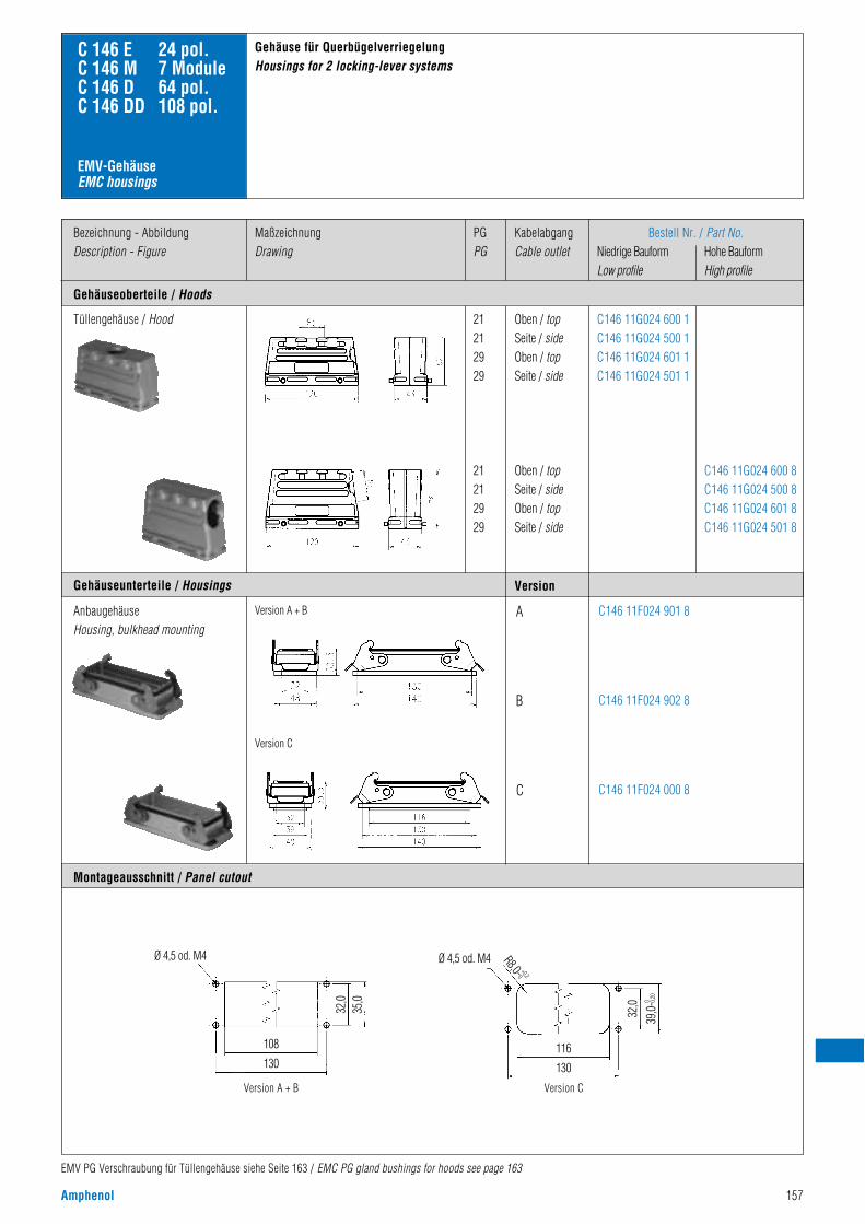
Amphenol 157
EMV-GehäuseEMC housings
Bezeichnung - AbbildungDescription - Figure
Gehäuseoberteile / Hoods
MaßzeichnungDrawing
PGPG
KabelabgangCable outlet
C146 11G024 600 8C146 11G024 500 8C146 11G024 601 8C146 11G024 501 8
C146 11G024 600 1C146 11G024 500 1C146 11G024 601 1C146 11G024 501 1
Tüllengehäuse / Hood
Bestell Nr. / Part No.Niedrige Bauform Hohe BauformLow profile High profile
Oben / topSeite / sideOben / topSeite / side
Oben / topSeite / sideOben / topSeite / side
21212929
21212929
Version
C146 11F024 901 8
C146 11F024 902 8
C146 11F024 000 8
A
B
C
AnbaugehäuseHousing, bulkhead mounting
Version C
Montageausschnitt / Panel cutout
Version A + B
C 146 E 24 pol.C 146 M 7 ModuleC 146 D 64 pol.C 146 DD 108 pol.
Gehäuse für QuerbügelverriegelungHousings for 2 locking-lever systems
EMV PG Verschraubung für Tüllengehäuse siehe Seite 163 / EMC PG gland bushings for hoods see page 163
Version A + B
Ø 4,5 od. M4
108
130
32,0
35,0
Version C
32,0
39,0-
0,20
0
R8,0-0+0,2
116
130
Ø 4,5 od. M4
Gehäuseunterteile / Housings

158 Amphenol
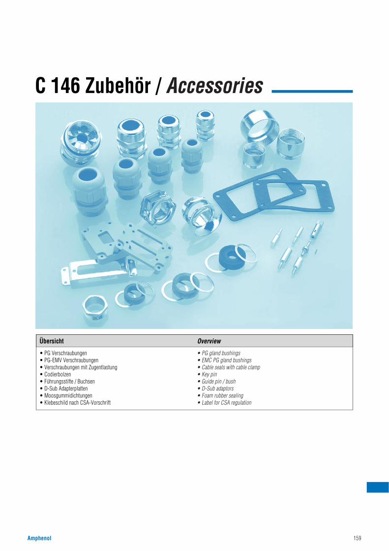
Amphenol 159
C 146 Zubehör / Accessories
• PG Verschraubungen• PG-EMV Verschraubungen• Verschraubungen mit Zugentlastung• Codierbolzen• Führungsstifte / Buchsen• D-Sub Adapterplatten• Moosgummidichtungen• Klebeschild nach CSA-Vorschrift
• PG gland bushings• EMC PG gland bushings• Cable seals with cable clamp• Key pin• Guide pin / bush• D-Sub adaptors• Foam rubber sealing• Label for CSA regulation
Übersicht Overview
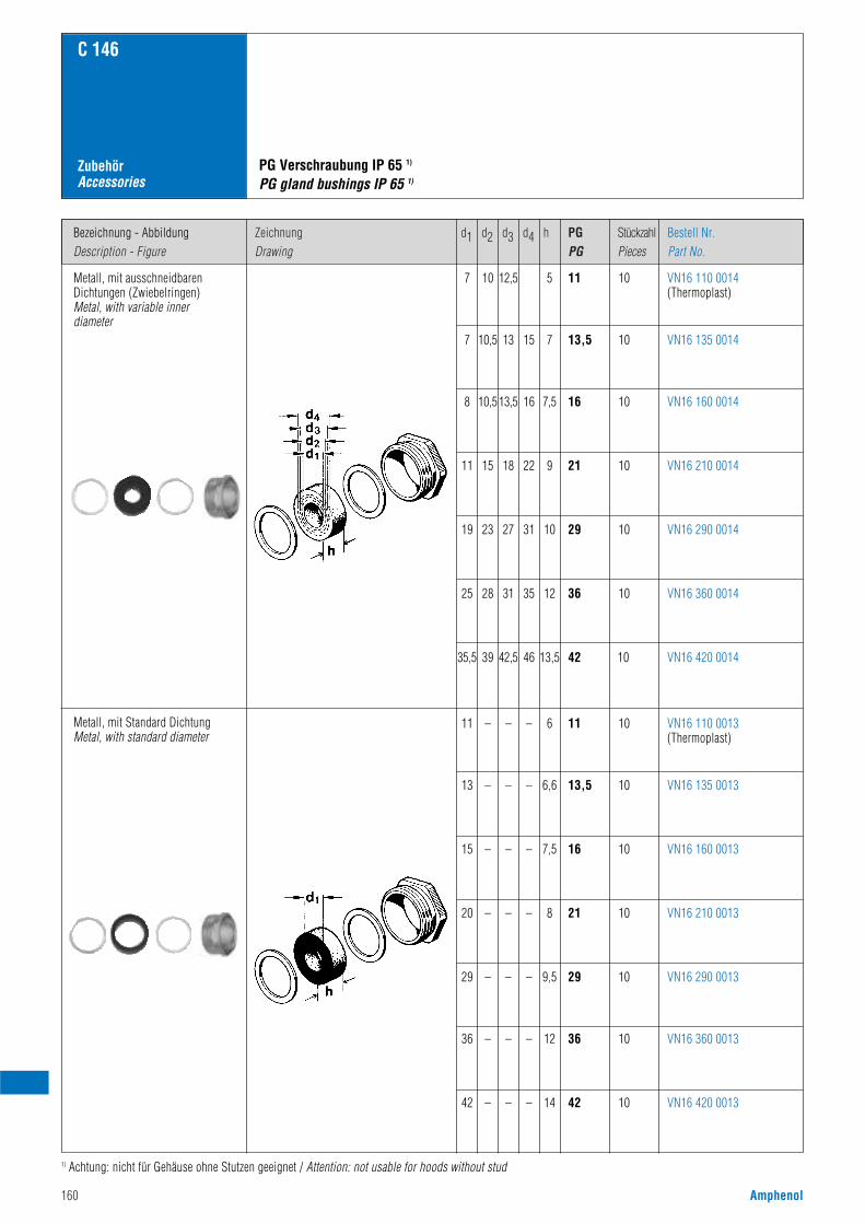
160 Amphenol
Bezeichnung - AbbildungDescription - Figure
ZeichnungDrawing
d1 d2 d3 d4 h PGPG
StückzahlPieces
Bestell Nr.Part No.
C 146
ZubehörAccessories
Metall, mit ausschneidbaren Dichtungen (Zwiebelringen) Metal, with variable innerdiameter
Metall, mit Standard Dichtung Metal, with standard diameter
PG Verschraubung IP 65 1)
PG gland bushings IP 65 1)
VN16 110 0014(Thermoplast)
7 10 12,5 5 11 10
VN16 135 00147 10,5 13 15 7 13,5 10
VN16 160 00148 10,5 13,5 16 7,5 16 10
VN16 210 001411 15 18 22 9 21 10
VN16 290 001419 23 27 31 10 29 10
VN16 360 001425 28 31 35 12 36 10
VN16 420 001435,5 39 42,5 46 13,5 42 10
VN16 110 0013(Thermoplast)
11 – – – 6 11 10
VN16 135 001313 – – – 6,6 13,5 10
VN16 160 001315 – – – 7,5 16 10
VN16 210 001320 – – – 8 21 10
VN16 290 001329 – – – 9,5 29 10
VN16 360 001336 – – – 12 36 10
VN16 420 001342 – – – 14 42 10
1) Achtung: nicht für Gehäuse ohne Stutzen geeignet / Attention: not usable for hoods without stud
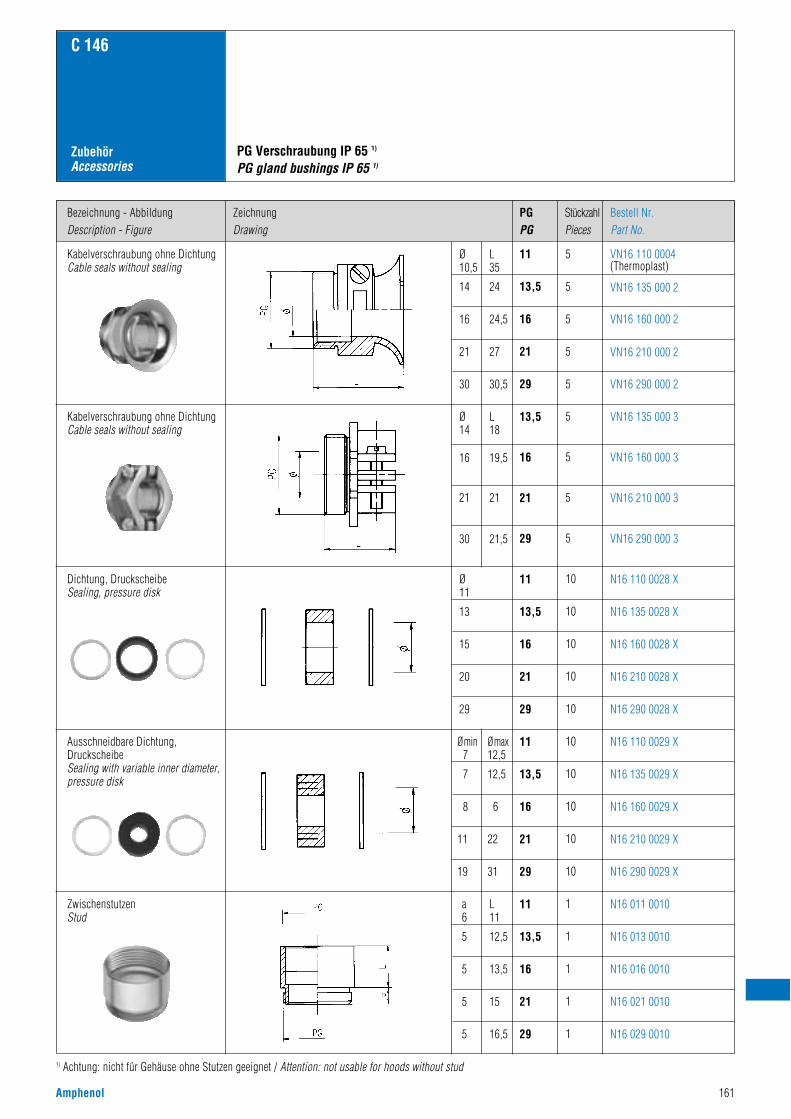
Amphenol 161
Bezeichnung - AbbildungDescription - Figure
ZeichnungDrawing
PGPG
StückzahlPieces
Bestell Nr.Part No.
C 146
ZubehörAccessories
Kabelverschraubung ohne DichtungCable seals without sealing
Kabelverschraubung ohne DichtungCable seals without sealing
Dichtung, DruckscheibeSealing, pressure disk
Ausschneidbare Dichtung,DruckscheibeSealing with variable inner diameter,pressure disk
ZwischenstutzenStud
PG Verschraubung IP 65 1)
PG gland bushings IP 65 1)
VN16 110 0004(Thermoplast)
11L35
24
24,5
27
30,5
Ø10,5
14
16
21
30
5
VN16 135 000 213,5 5
VN16 160 000 216 5
VN16 210 000 221 5
VN16 290 000 229 5
VN16 135 000 313,5 5
VN16 160 000 316 5
VN16 210 000 321 5
VN16 290 000 329 5
N16 110 0028 X11 10
N16 135 0028 X13,5 10
N16 160 0028 X16 10
N16 210 0028 X21 10
N16 290 0028 X29 10
N16 110 0029 X11 10
N16 135 0029 X13,5 10
N16 160 0029 X16 10
N16 210 0029 X21 10
N16 290 0029 X29 10
N16 011 001011 1
N16 013 001013,5 1
N16 016 001016 1
N16 021 001021 1
N16 029 001029 1
1) Achtung: nicht für Gehäuse ohne Stutzen geeignet / Attention: not usable for hoods without stud
L18
19,5
21
21,5
Ø14
16
21
30
Ø11
13
15
20
29
Ømax12,5
12,5
6
22
31
Ømin7
7
8
11
19
L11
12,5
13,5
15
16,5
a6
5
5
5
5
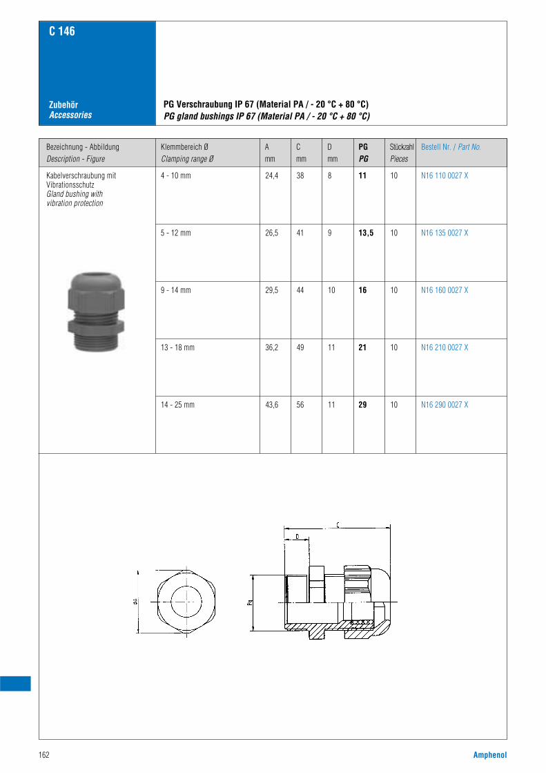
162 Amphenol
Bezeichnung - AbbildungDescription - Figure
Klemmbereich ØClamping range Ø
PGPG
StückzahlPieces
Dmm
Cmm
Amm
Bestell Nr. / Part No.
C 146
ZubehörAccessories
Kabelverschraubung mitVibrationsschutzGland bushing withvibration protection
4 - 10 mm
PG Verschraubung IP 67 (Material PA / - 20 °C + 80 °C)PG gland bushings IP 67 (Material PA / - 20 °C + 80 °C)
N16 110 0027 X11 1083824,4
5 - 12 mm N16 135 0027 X13,5 1094126,5
9 - 14 mm N16 160 0027 X16 10104429,5
13 - 18 mm N16 210 0027 X21 10114936,2
14 - 25 mm N16 290 0027 X29 10115643,6
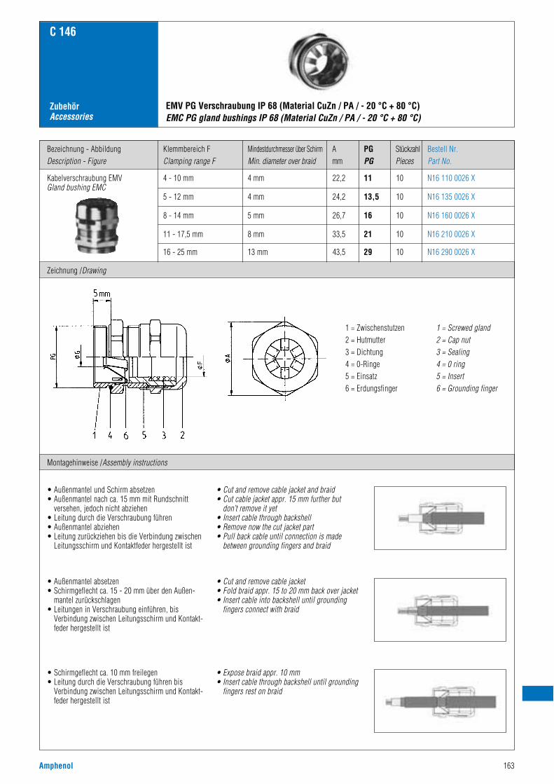
Amphenol 163
Bezeichnung - AbbildungDescription - Figure
Zeichnung /Drawing
Klemmbereich FClamping range F
PGPG
Amm
Mindestdurchmesser über SchirmMin. diameter over braid
StückzahlPieces
Bestell Nr.Part No.
C 146
ZubehörAccessories
Kabelverschraubung EMVGland bushing EMC
4 - 10 mm
EMV PG Verschraubung IP 68 (Material CuZn / PA / - 20 °C + 80 °C)EMC PG gland bushings IP 68 (Material CuZn / PA / - 20 °C + 80 °C)
N16 110 0026 X11 104 mm 22,2
5 - 12 mm N16 135 0026 X13,5 104 mm 24,2
8 - 14 mm N16 160 0026 X16 105 mm 26,7
11 - 17,5 mm N16 210 0026 X21 108 mm 33,5
16 - 25 mm N16 290 0026 X29 1013 mm 43,5
1 = Zwischenstutzen2 = Hutmutter3 = Dichtung4 = 0-Ringe5 = Einsatz6 = Erdungsfinger
1 = Screwed gland2 = Cap nut3 = Sealing4 = 0 ring5 = Insert6 = Grounding finger
• Außenmantel und Schirm absetzen• Außenmantel nach ca. 15 mm mit Rundschnitt
versehen, jedoch nicht abziehen• Leitung durch die Verschraubung führen• Außenmantel abziehen• Leitung zurückziehen bis die Verbindung zwischen
Leitungsschirm und Kontaktfeder hergestellt ist
• Cut and remove cable jacket and braid• Cut cable jacket appr. 15 mm further but
don’t remove it yet• Insert cable through backshell• Remove now the cut jacket part• Pull back cable until connection is made
between grounding fingers and braid
• Außenmantel absetzen• Schirmgeflecht ca. 15 - 20 mm über den Außen-
mantel zurückschlagen• Leitungen in Verschraubung einführen, bis
Verbindung zwischen Leitungsschirm und Kontakt-feder hergestellt ist
• Cut and remove cable jacket• Fold braid appr. 15 to 20 mm back over jacket• Insert cable into backshell until grounding
fingers connect with braid
• Schirmgeflecht ca. 10 mm freilegen• Leitung durch die Verschraubung führen bis
Verbindung zwischen Leitungsschirm und Kontakt-feder hergestellt ist
• Expose braid appr. 10 mm• Insert cable through backshell until grounding
fingers rest on braid
Montagehinweise /Assembly instructions
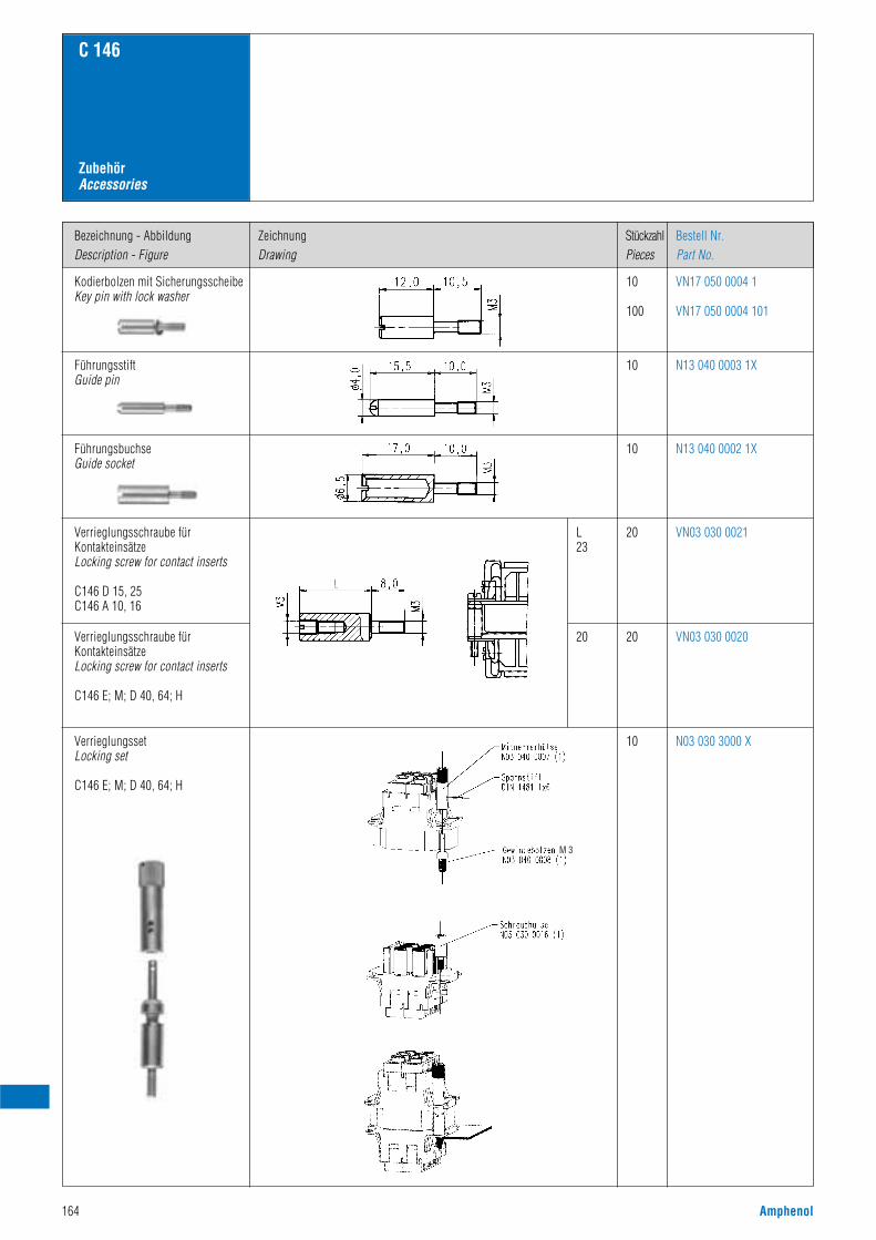
164 Amphenol
C 146
ZubehörAccessories
Bezeichnung - AbbildungDescription - Figure
ZeichnungDrawing
StückzahlPieces
Bestell Nr.Part No.
Kodierbolzen mit SicherungsscheibeKey pin with lock washer
VN17 050 0004 1
VN17 050 0004 101
10
100
FührungsstiftGuide pin
N13 040 0003 1X10
FührungsbuchseGuide socket
N13 040 0002 1X10
Verrieglungsschraube fürKontakteinsätzeLocking screw for contact inserts
C146 D 15, 25C146 A 10, 16
VN03 030 002120
Verrieglungsschraube fürKontakteinsätzeLocking screw for contact inserts
C146 E; M; D 40, 64; H
VN03 030 002020
L23
20
VerrieglungssetLocking set
C146 E; M; D 40, 64; H
N03 030 3000 X10
M 3
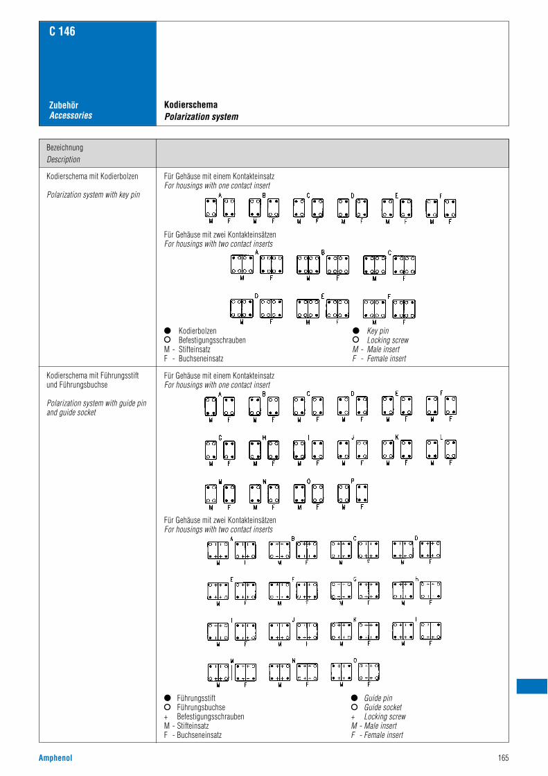
Amphenol 165
C 146
ZubehörAccessories
BezeichnungDescription
Kodierschema mit Kodierbolzen
Polarization system with key pin
Für Gehäuse mit einem KontakteinsatzFor housings with one contact insert
Für Gehäuse mit zwei KontakteinsätzenFor housings with two contact inserts
KodierbolzenBefestigungsschrauben
M - StifteinsatzF - Buchseneinsatz
Key pinLocking screw
M - Male insertF - Female insert
Kodierschema mit Führungsstiftund Führungsbuchse
Polarization system with guide pinand guide socket
KodierschemaPolarization system
Für Gehäuse mit einem KontakteinsatzFor housings with one contact insert
Für Gehäuse mit zwei KontakteinsätzenFor housings with two contact inserts
FührungsstiftFührungsbuchse
+ BefestigungsschraubenM - StifteinsatzF - Buchseneinsatz
Guide pinGuide socket
+ Locking screwM - Male insertF - Female insert
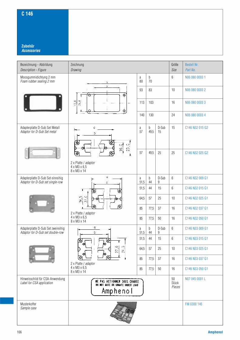
166 Amphenol
Bezeichnung - AbbildungDescription - Figure
ZeichnungDrawing
GrößeSize
Bestell Nr.Part No.
C 146
ZubehörAccessories
Moosgummidichtung 2 mmFoam rubber sealing 2 mm
Adapterplatte D-Sub Set MetallAdaptor for D-Sub Set metal
Adapterplatte D-Sub Set einreihigAdaptor for D-Sub set single-row
Adapterplatte D-Sub Set zweireihigAdaptor for D-Sub set double-row
Hinweisschild für CSA-AnwendungLabel for CSA application
MusterkofferSample case
N06 080 0003 16
N06 080 0003 210
N06 080 0003 316
N06 080 0003 424
C146 N32 015 G215D-Sub15
C146 N32 025 G22525
C146 N32 009 G16
C146 N32 015 G16
C146 N32 025 G110
C146 N32 037 G116
C146 N32 050 G11650
C146 N33 009 G16
C146 N33 015 G16
C146 N33 025 G110
C146 N33 037 G116
C146 N33 050 G116
D-Sub9
15
25
37
D-Sub9
15
25
37
50
N07 045 0001 L
FM 0300 146
50StückPieces
b70
83
103
130
a80
93
113
140
b49,5
49,5
a57
57
2 x Platte / adaptor4 x M3 x 6,58 x M3 x 14
2 x Platte / adaptor4 x M3 x 6,58 x M3 x 14
b44
44
57
77,5
77,5
a51,5
51,5
64,5
85
85
2 x Platte / adaptor4 x M3 x 6,58 x M3 x 14
b44
44
57
77,5
77,5
a51,5
51,5
64,5
85
85

Amphenol 167
SerieSeries
Maßzeichnung EinzelkontaktDrawing single contact
Maßzeichnung BandkontaktDrawing contacts on reel
C 146
Maßzeichnungen KontakteDrawings contacts
C146 D, M .N01 016 0003 1 .N02 016 0003 1
.N01 016 0002 1 .N02 016 0002 1
.N01 016 0015 11) .N02 016 0015 11)
.N01 016 0005 1 .N02 016 0005 1
.N01 016 0016 11) .N02 016 0016 11)
.N01 025 0001 1 .N02 025 0001 1
.N01 025 0010 1 .N02 025 0010 1
17RR-D2M-xx xxx 17RR-D2F-xx xxx
17RR-D1M-xx xxx 17RR-D1F-xx xxx
C146 E, M
C146 M
Gestanzte CrimpkontakteStamped crimp contacts
1) gekennzeichnet mit „H“ / marked with „H“

168 Amphenol
SerieSeries
MaßzeichnungDrawing
QuerschnittWire gauge
A B StückzahlPieces
Bestell Nr.Part No.
C 146
Maßzeichnungen KontakteDrawings contacts
C146 D, M .N01 016 002X
.N02 016 002X
.N01 025 003X
.N02 025 003X
.N01 025 00XX
.N02 025 00XX
.N01 036 000X
.N02 036 000X
C146 E
C146 M
VN01 016 0024 1C
VN01 016 0025 1C
VN01 016 0026 1C
VN01 016 0027 1C
VN01 016 0028 1C
VN02 016 0024 1C
VN02 016 0025 1C
VN02 016 0026 1C
VN02 016 0027 1C
VN02 016 0028 1C
VN01 025 0035 1
VN01 025 0036 1
VN01 025 0037 1
VN01 025 0038 1
VN01 025 0039 1
VN02 025 0035 1
VN02 025 0036 1
VN02 025 0037 1
VN02 025 0038 1
VN02 025 0039 1
VN01 025 0029 1C
VN01 025 0030 1C
VN01 025 0031 1C
VN01 025 0032 1C
VN01 025 0033 1C
VN02 025 0029 1C
VN02 025 0030 1C
VN02 025 0031 1C
VN02 025 0032 1C
VN02 025 0033 1C
VN01 036 0004 1C
VN01 036 0005 1C
VN01 036 0001 1C
VN01 036 0002 1C
VN01 036 0003 1C
VN02 036 0004 1C
VN02 036 0005 1C
VN02 036 0001 1C
VN02 036 0002 1C
VN02 036 0003 1C
100
100
100
100
100
100
100
100
100
100
100
100
100
100
100
100
100
100
100
100
100
100
100
100
100
100
100
100
100
100
100
100
100
100
100
100
100
100
100
100
2,6
2,6
2,6
3,0
3,2
2,6
2,6
2,6
3,0
3,2
2,6
2,6
3,0
3,2
4,0
2,6
2,6
3,0
3,2
4,0
2,6
2,6
3,0
3,45
3,9
2,6
2,6
3,0
3,45
3,9
3,0
3,45
3,9
4,9
5,9
3,0
3,45
3,9
4,9
5,9
0,9
1,1
1,45
1,75
2,25
0,9
1,1
1,45
1,75
2,25
1,1
1,45
1,75
2,3
2,9
1,1
1,45
1,75
2,3
2,9
1,1
1,45
1,75
2,25
2,85
1,1
1,45
1,75
2,25
2,85
1,75
2,25
2,85
3,55
4,4
1,75
2,25
2,85
3,55
4,4
0,14 - 0,37
0,5
0,75 - 1,0
1,5
2,5
0,14 - 0,37
0,5
0,75 - 1,0
1,5
2,5
0,5
0,75 - 1,0
1,5
2,5
4,0
0,5
0,75 - 1,0
1,5
2,5
4,0
0,5
0,75 - 1,0
1,5
2,5
4,0
0,5
0,75 - 1,0
1,5
2,5
4,0
1,5
2,5
4,0
6,0
10,0
1,5
2,5
4,0
6,0
10,0
Gedrehte CrimpkontakteTurned crimp contacts
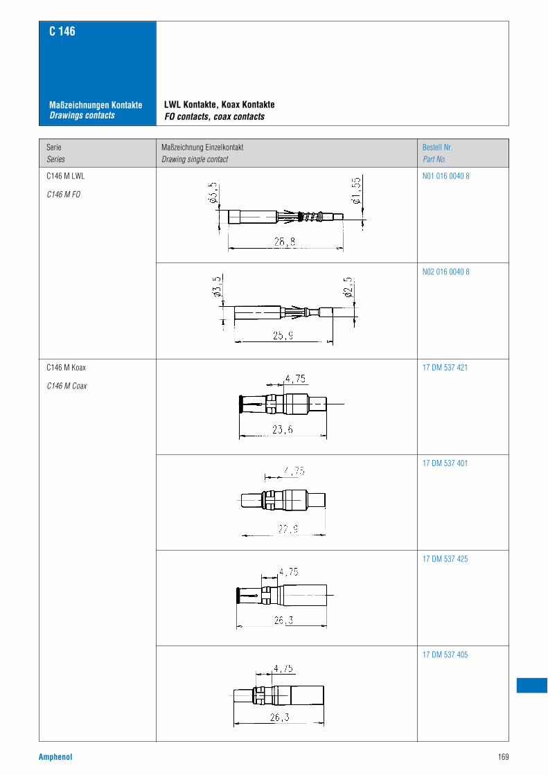
Amphenol 169
SerieSeries
Maßzeichnung EinzelkontaktDrawing single contact
Bestell Nr.Part No.
C 146
Maßzeichnungen KontakteDrawings contacts
C146 M LWL
C146 M FO
C146 M Koax
C146 M Coax
N01 016 0040 8
N02 016 0040 8
17 DM 537 421
17 DM 537 401
17 DM 537 425
17 DM 537 405
LWL Kontakte, Koax KontakteFO contacts, coax contacts
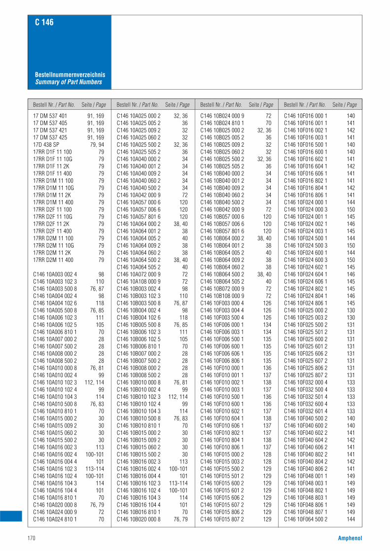
Bestell Nr. / Part No. Seite / Page Bestell Nr. / Part No. Seite / Page Bestell Nr. / Part No. Seite / Page Bestell Nr. / Part No. Seite / Page
170 Amphenol
C 146
17 DM 537 401 91, 16917 DM 537 405 91, 16917 DM 537 421 91, 16917 DM 537 425 91, 16917D 438 SP 79, 9417RR D1F 11 100 7917RR D1F 11 10G 7917RR D1F 11 2K 7917RR D1F 11 400 7917RR D1M 11 100 7917RR D1M 11 10G 7917RR D1M 11 2K 7917RR D1M 11 400 7917RR D2F 11 100 7917RR D2F 11 10G 7917RR D2F 11 2K 7917RR D2F 11 400 7917RR D2M 11 100 7917RR D2M 11 10G 7917RR D2M 11 2K 7917RR D2M 11 400 79
C146 10A003 002 4 98C146 10A003 102 3 110C146 10A003 500 8 76, 87C146 10A004 002 4 98C146 10A004 102 6 118C146 10A005 500 8 76, 85C146 10A006 102 3 111C146 10A006 102 5 105C146 10A006 810 1 70C146 10A007 000 2 28C146 10A007 500 2 28C146 10A008 000 2 28C146 10A008 500 2 28C146 10A010 000 8 76, 81C146 10A010 002 4 99C146 10A010 102 3 112, 114C146 10A010 102 4 99C146 10A010 104 3 114C146 10A010 500 8 76, 83C146 10A010 810 1 70C146 10A015 000 2 30C146 10A015 009 2 30C146 10A015 060 2 30C146 10A015 500 2 30C146 10A016 002 3 113C146 10A016 002 4 100-101C146 10A016 004 4 101C146 10A016 102 3 113-114C146 10A016 102 4 100-101C146 10A016 104 3 114C146 10A016 104 4 101C146 10A016 810 1 70C146 10A020 000 8 76, 79C146 10A024 000 9 72C146 10A024 810 1 70
C146 10A025 000 2 32, 36C146 10A025 005 2 36C146 10A025 009 2 32C146 10A025 060 2 32C146 10A025 500 2 32, 36C146 10A025 505 2 36C146 10A040 000 2 34C146 10A040 001 2 34C146 10A040 009 2 34C146 10A040 060 2 34C146 10A040 500 2 34C146 10A042 000 9 72C146 10A057 000 6 120C146 10A057 006 6 120C146 10A057 801 6 120C146 10A064 000 2 38, 40C146 10A064 001 2 38C146 10A064 005 2 40C146 10A064 009 2 38C146 10A064 060 2 38C146 10A064 500 2 38, 40C146 10A064 505 2 40C146 10A072 000 9 72C146 10A108 000 9 72C146 10B003 002 4 98C146 10B003 102 3 110C146 10B003 500 8 76, 87C146 10B004 002 4 98C146 10B004 102 6 118C146 10B005 500 8 76, 85C146 10B006 102 3 111C146 10B006 102 5 105C146 10B006 810 1 70C146 10B007 000 2 28C146 10B007 500 2 28C146 10B008 000 2 28C146 10B008 500 2 28C146 10B010 000 8 76, 81C146 10B010 002 4 99C146 10B010 102 3 112, 114C146 10B010 102 4 99C146 10B010 104 3 114C146 10B010 500 8 76, 83C146 10B010 810 1 70C146 10B015 000 2 30C146 10B015 009 2 30C146 10B015 060 2 30C146 10B015 500 2 30C146 10B016 002 3 113C146 10B016 002 4 100-101C146 10B016 004 4 101C146 10B016 102 3 113-114C146 10B016 102 4 100-101C146 10B016 104 3 114C146 10B016 104 4 101C146 10B016 810 1 70C146 10B020 000 8 76, 79
C146 10B024 000 9 72C146 10B024 810 1 70C146 10B025 000 2 32, 36C146 10B025 005 2 36C146 10B025 009 2 32C146 10B025 060 2 32C146 10B025 500 2 32, 36C146 10B025 505 2 36C146 10B040 000 2 34C146 10B040 001 2 34C146 10B040 009 2 34C146 10B040 060 2 34C146 10B040 500 2 34C146 10B042 000 9 72C146 10B057 000 6 120C146 10B057 006 6 120C146 10B057 801 6 120C146 10B064 000 2 38, 40C146 10B064 001 2 38C146 10B064 005 2 40C146 10B064 009 2 38C146 10B064 060 2 38C146 10B064 500 2 38, 40C146 10B064 505 2 40C146 10B072 000 9 72C146 10B108 000 9 72C146 10F003 000 4 126C146 10F003 004 4 126C146 10F003 500 4 126C146 10F006 000 1 134C146 10F006 003 1 134C146 10F006 500 1 135C146 10F006 600 1 135C146 10F006 606 1 135C146 10F006 806 1 135C146 10F010 000 1 136C146 10F010 001 1 137C146 10F010 002 1 138C146 10F010 003 1 137C146 10F010 500 1 136C146 10F010 600 1 136C146 10F010 602 1 137C146 10F010 604 1 138C146 10F010 606 1 137C146 10F010 802 1 137C146 10F010 804 1 138C146 10F010 806 1 137C146 10F015 000 2 128C146 10F015 003 2 128C146 10F015 500 2 129C146 10F015 501 2 129C146 10F015 600 2 129C146 10F015 601 2 129C146 10F015 606 2 129C146 10F015 607 2 129C146 10F015 806 2 129C146 10F015 807 2 129
C146 10F016 000 1 140C146 10F016 001 1 141C146 10F016 002 1 142C146 10F016 003 1 141C146 10F016 500 1 140C146 10F016 600 1 140C146 10F016 602 1 141C146 10F016 604 1 142C146 10F016 606 1 141C146 10F016 802 1 141C146 10F016 804 1 142C146 10F016 806 1 141C146 10F024 000 1 144C146 10F024 000 3 150C146 10F024 001 1 145C146 10F024 002 1 146C146 10F024 003 1 145C146 10F024 500 1 144C146 10F024 500 3 150C146 10F024 600 1 144C146 10F024 600 3 150C146 10F024 602 1 145C146 10F024 604 1 146C146 10F024 606 1 145C146 10F024 802 1 145C146 10F024 804 1 146C146 10F024 806 1 145C146 10F025 000 2 130C146 10F025 003 2 130C146 10F025 500 2 131C146 10F025 501 2 131C146 10F025 600 2 131C146 10F025 601 2 131C146 10F025 606 2 131C146 10F025 607 2 131C146 10F025 806 2 131C146 10F025 807 2 131C146 10F032 000 4 133C146 10F032 500 4 133C146 10F032 501 4 133C146 10F032 600 4 133C146 10F032 601 4 133C146 10F040 500 2 140C146 10F040 600 2 140C146 10F040 602 2 141C146 10F040 604 2 142C146 10F040 606 2 141C146 10F040 802 2 141C146 10F040 804 2 142C146 10F040 806 2 141C146 10F048 001 1 149C146 10F048 003 1 149C146 10F048 802 1 149C146 10F048 803 1 149C146 10F048 806 1 149C146 10F048 807 1 149C146 10F064 500 2 144
BestellnummernverzeichnisSummary of Part Numbers
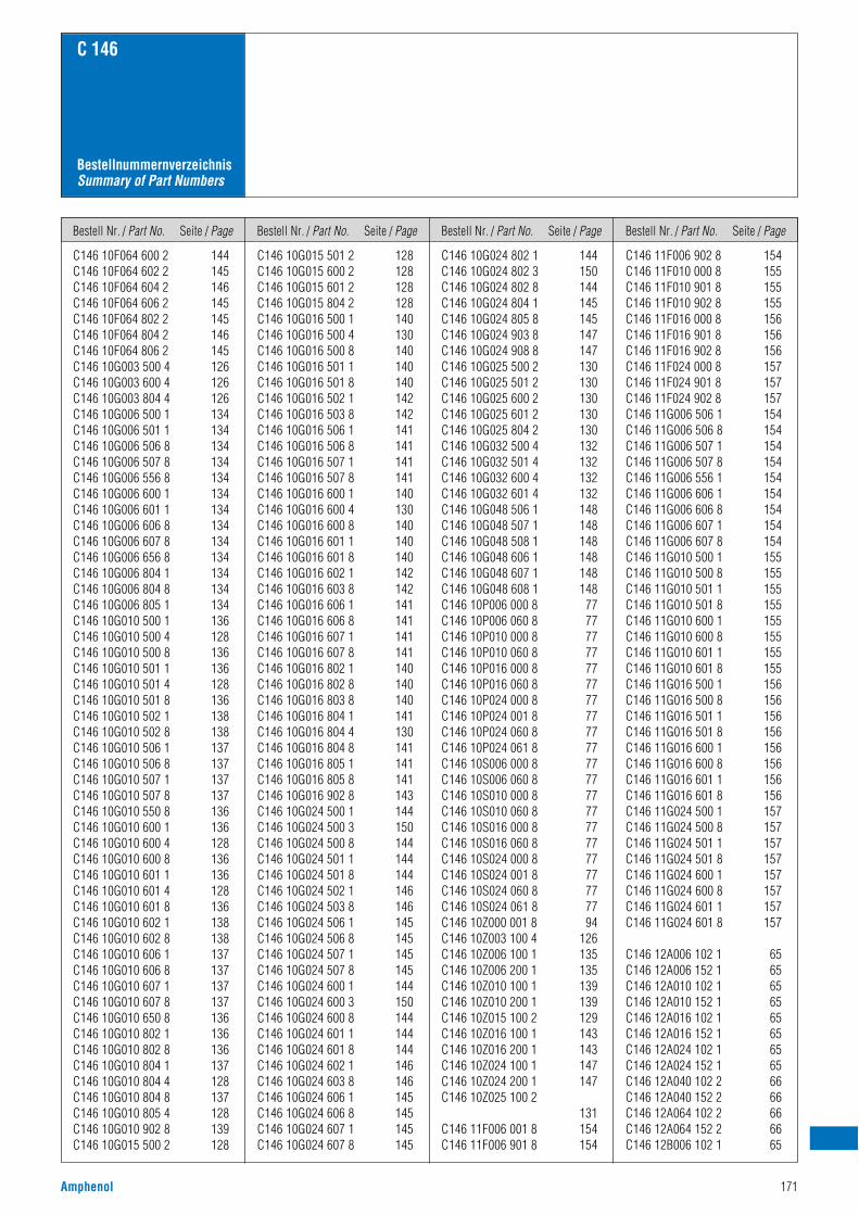
Bestell Nr. / Part No. Seite / Page Bestell Nr. / Part No. Seite / Page Bestell Nr. / Part No. Seite / Page Bestell Nr. / Part No. Seite / Page
Amphenol 171
C 146
BestellnummernverzeichnisSummary of Part Numbers
C146 10F064 600 2 144C146 10F064 602 2 145C146 10F064 604 2 146C146 10F064 606 2 145C146 10F064 802 2 145C146 10F064 804 2 146C146 10F064 806 2 145C146 10G003 500 4 126C146 10G003 600 4 126C146 10G003 804 4 126C146 10G006 500 1 134C146 10G006 501 1 134C146 10G006 506 8 134C146 10G006 507 8 134C146 10G006 556 8 134C146 10G006 600 1 134C146 10G006 601 1 134C146 10G006 606 8 134C146 10G006 607 8 134C146 10G006 656 8 134C146 10G006 804 1 134C146 10G006 804 8 134C146 10G006 805 1 134C146 10G010 500 1 136C146 10G010 500 4 128C146 10G010 500 8 136C146 10G010 501 1 136C146 10G010 501 4 128C146 10G010 501 8 136C146 10G010 502 1 138C146 10G010 502 8 138C146 10G010 506 1 137C146 10G010 506 8 137C146 10G010 507 1 137C146 10G010 507 8 137C146 10G010 550 8 136C146 10G010 600 1 136C146 10G010 600 4 128C146 10G010 600 8 136C146 10G010 601 1 136C146 10G010 601 4 128C146 10G010 601 8 136C146 10G010 602 1 138C146 10G010 602 8 138C146 10G010 606 1 137C146 10G010 606 8 137C146 10G010 607 1 137C146 10G010 607 8 137C146 10G010 650 8 136C146 10G010 802 1 136C146 10G010 802 8 136C146 10G010 804 1 137C146 10G010 804 4 128C146 10G010 804 8 137C146 10G010 805 4 128C146 10G010 902 8 139C146 10G015 500 2 128
C146 10G015 501 2 128C146 10G015 600 2 128C146 10G015 601 2 128C146 10G015 804 2 128C146 10G016 500 1 140C146 10G016 500 4 130C146 10G016 500 8 140C146 10G016 501 1 140C146 10G016 501 8 140C146 10G016 502 1 142C146 10G016 503 8 142C146 10G016 506 1 141C146 10G016 506 8 141C146 10G016 507 1 141C146 10G016 507 8 141C146 10G016 600 1 140C146 10G016 600 4 130C146 10G016 600 8 140C146 10G016 601 1 140C146 10G016 601 8 140C146 10G016 602 1 142C146 10G016 603 8 142C146 10G016 606 1 141C146 10G016 606 8 141C146 10G016 607 1 141C146 10G016 607 8 141C146 10G016 802 1 140C146 10G016 802 8 140C146 10G016 803 8 140C146 10G016 804 1 141C146 10G016 804 4 130C146 10G016 804 8 141C146 10G016 805 1 141C146 10G016 805 8 141C146 10G016 902 8 143C146 10G024 500 1 144C146 10G024 500 3 150C146 10G024 500 8 144C146 10G024 501 1 144C146 10G024 501 8 144C146 10G024 502 1 146C146 10G024 503 8 146C146 10G024 506 1 145C146 10G024 506 8 145C146 10G024 507 1 145C146 10G024 507 8 145C146 10G024 600 1 144C146 10G024 600 3 150C146 10G024 600 8 144C146 10G024 601 1 144C146 10G024 601 8 144C146 10G024 602 1 146C146 10G024 603 8 146C146 10G024 606 1 145C146 10G024 606 8 145C146 10G024 607 1 145C146 10G024 607 8 145
C146 10G024 802 1 144C146 10G024 802 3 150C146 10G024 802 8 144C146 10G024 804 1 145C146 10G024 805 8 145C146 10G024 903 8 147C146 10G024 908 8 147C146 10G025 500 2 130C146 10G025 501 2 130C146 10G025 600 2 130C146 10G025 601 2 130C146 10G025 804 2 130C146 10G032 500 4 132C146 10G032 501 4 132C146 10G032 600 4 132C146 10G032 601 4 132C146 10G048 506 1 148C146 10G048 507 1 148C146 10G048 508 1 148C146 10G048 606 1 148C146 10G048 607 1 148C146 10G048 608 1 148C146 10P006 000 8 77C146 10P006 060 8 77C146 10P010 000 8 77C146 10P010 060 8 77C146 10P016 000 8 77C146 10P016 060 8 77C146 10P024 000 8 77C146 10P024 001 8 77C146 10P024 060 8 77C146 10P024 061 8 77C146 10S006 000 8 77C146 10S006 060 8 77C146 10S010 000 8 77C146 10S010 060 8 77C146 10S016 000 8 77C146 10S016 060 8 77C146 10S024 000 8 77C146 10S024 001 8 77C146 10S024 060 8 77C146 10S024 061 8 77C146 10Z000 001 8 94C146 10Z003 100 4 126C146 10Z006 100 1 135C146 10Z006 200 1 135C146 10Z010 100 1 139C146 10Z010 200 1 139C146 10Z015 100 2 129C146 10Z016 100 1 143C146 10Z016 200 1 143C146 10Z024 100 1 147C146 10Z024 200 1 147C146 10Z025 100 2
131C146 11F006 001 8 154C146 11F006 901 8 154
C146 11F006 902 8 154C146 11F010 000 8 155C146 11F010 901 8 155C146 11F010 902 8 155C146 11F016 000 8 156C146 11F016 901 8 156C146 11F016 902 8 156C146 11F024 000 8 157C146 11F024 901 8 157C146 11F024 902 8 157C146 11G006 506 1 154C146 11G006 506 8 154C146 11G006 507 1 154C146 11G006 507 8 154C146 11G006 556 1 154C146 11G006 606 1 154C146 11G006 606 8 154C146 11G006 607 1 154C146 11G006 607 8 154C146 11G010 500 1 155C146 11G010 500 8 155C146 11G010 501 1 155C146 11G010 501 8 155C146 11G010 600 1 155C146 11G010 600 8 155C146 11G010 601 1 155C146 11G010 601 8 155C146 11G016 500 1 156C146 11G016 500 8 156C146 11G016 501 1 156C146 11G016 501 8 156C146 11G016 600 1 156C146 11G016 600 8 156C146 11G016 601 1 156C146 11G016 601 8 156C146 11G024 500 1 157C146 11G024 500 8 157C146 11G024 501 1 157C146 11G024 501 8 157C146 11G024 600 1 157C146 11G024 600 8 157C146 11G024 601 1 157C146 11G024 601 8 157
C146 12A006 102 1 65C146 12A006 152 1 65C146 12A010 102 1 65C146 12A010 152 1 65C146 12A016 102 1 65C146 12A016 152 1 65C146 12A024 102 1 65C146 12A024 152 1 65C146 12A040 102 2 66C146 12A040 152 2 66C146 12A064 102 2 66C146 12A064 152 2 66C146 12B006 102 1 65
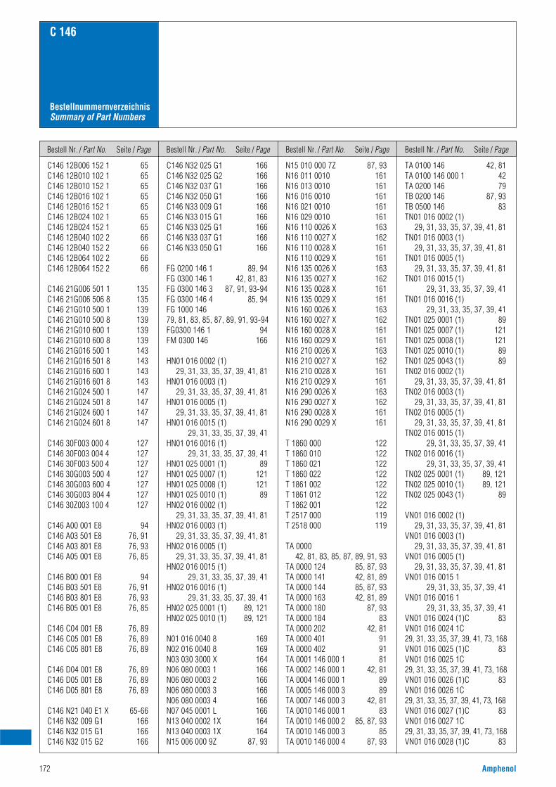
Bestell Nr. / Part No. Seite / Page Bestell Nr. / Part No. Seite / Page Bestell Nr. / Part No. Seite / Page Bestell Nr. / Part No. Seite / Page
172 Amphenol
C 146
BestellnummernverzeichnisSummary of Part Numbers
C146 12B006 152 1 65C146 12B010 102 1 65C146 12B010 152 1 65C146 12B016 102 1 65C146 12B016 152 1 65C146 12B024 102 1 65C146 12B024 152 1 65C146 12B040 102 2 66C146 12B040 152 2 66C146 12B064 102 2 66C146 12B064 152 2 66
C146 21G006 501 1 135C146 21G006 506 8 135C146 21G010 500 1 139C146 21G010 500 8 139C146 21G010 600 1 139C146 21G010 600 8 139C146 21G016 500 1 143C146 21G016 501 8 143C146 21G016 600 1 143C146 21G016 601 8 143C146 21G024 500 1 147C146 21G024 501 8 147C146 21G024 600 1 147C146 21G024 601 8 147
C146 30F003 000 4 127C146 30F003 004 4 127C146 30F003 500 4 127C146 30G003 500 4 127C146 30G003 600 4 127C146 30G003 804 4 127C146 30Z003 100 4 127
C146 A00 001 E8 94C146 A03 501 E8 76, 91C146 A03 801 E8 76, 93C146 A05 001 E8 76, 85
C146 B00 001 E8 94C146 B03 501 E8 76, 91C146 B03 801 E8 76, 93C146 B05 001 E8 76, 85
C146 C04 001 E8 76, 89C146 C05 001 E8 76, 89C146 C05 801 E8 76, 89
C146 D04 001 E8 76, 89C146 D05 001 E8 76, 89C146 D05 801 E8 76, 89
C146 N21 040 E1 X 65-66C146 N32 009 G1 166C146 N32 015 G1 166C146 N32 015 G2 166
C146 N32 025 G1 166C146 N32 025 G2 166C146 N32 037 G1 166C146 N32 050 G1 166C146 N33 009 G1 166C146 N33 015 G1 166C146 N33 025 G1 166C146 N33 037 G1 166C146 N33 050 G1 166
FG 0200 146 1 89, 94FG 0300 146 1 42, 81, 83FG 0300 146 3 87, 91, 93-94FG 0300 146 4 85, 94FG 1000 14679, 81, 83, 85, 87, 89, 91, 93-94FG0300 146 1 94FM 0300 146 166
HN01 016 0002 (1)29, 31, 33, 35, 37, 39, 41, 81
HN01 016 0003 (1)29, 31, 33, 35, 37, 39, 41, 81
HN01 016 0005 (1)29, 31, 33, 35, 37, 39, 41, 81
HN01 016 0015 (1)29, 31, 33, 35, 37, 39, 41
HN01 016 0016 (1)29, 31, 33, 35, 37, 39, 41
HN01 025 0001 (1) 89HN01 025 0007 (1) 121HN01 025 0008 (1) 121HN01 025 0010 (1) 89HN02 016 0002 (1)
29, 31, 33, 35, 37, 39, 41, 81HN02 016 0003 (1)
29, 31, 33, 35, 37, 39, 41, 81HN02 016 0005 (1)
29, 31, 33, 35, 37, 39, 41, 81HN02 016 0015 (1)
29, 31, 33, 35, 37, 39, 41HN02 016 0016 (1)
29, 31, 33, 35, 37, 39, 41HN02 025 0001 (1) 89, 121HN02 025 0010 (1) 89, 121
N01 016 0040 8 169N02 016 0040 8 169N03 030 3000 X 164N06 080 0003 1 166N06 080 0003 2 166N06 080 0003 3 166N06 080 0003 4 166N07 045 0001 L 166N13 040 0002 1X 164N13 040 0003 1X 164N15 006 000 9Z 87, 93
N15 010 000 7Z 87, 93N16 011 0010 161N16 013 0010 161N16 016 0010 161N16 021 0010 161N16 029 0010 161N16 110 0026 X 163N16 110 0027 X 162N16 110 0028 X 161N16 110 0029 X 161N16 135 0026 X 163N16 135 0027 X 162N16 135 0028 X 161N16 135 0029 X 161N16 160 0026 X 163N16 160 0027 X 162N16 160 0028 X 161N16 160 0029 X 161N16 210 0026 X 163N16 210 0027 X 162N16 210 0028 X 161N16 210 0029 X 161N16 290 0026 X 163N16 290 0027 X 162N16 290 0028 X 161N16 290 0029 X 161
T 1860 000 122T 1860 010 122T 1860 021 122T 1860 022 122T 1861 002 122T 1861 012 122T 1862 001 122T 2517 000 119T 2518 000 119
TA 000042, 81, 83, 85, 87, 89, 91, 93
TA 0000 124 85, 87, 93TA 0000 141 42, 81, 89TA 0000 144 85, 87, 93TA 0000 163 42, 81, 89TA 0000 180 87, 93TA 0000 184 83TA 0000 202 42, 81TA 0000 401 91TA 0000 402 91TA 0001 146 000 1 81TA 0002 146 000 1 42, 81TA 0004 146 000 1 89TA 0005 146 000 3 89TA 0007 146 000 3 42, 81TA 0010 146 000 1 83TA 0010 146 000 2 85, 87, 93TA 0010 146 000 3 85TA 0010 146 000 4 87, 93
TA 0100 146 42, 81TA 0100 146 000 1 42TA 0200 146 79TB 0200 146 87, 93TB 0500 146 83TN01 016 0002 (1)
29, 31, 33, 35, 37, 39, 41, 81TN01 016 0003 (1)
29, 31, 33, 35, 37, 39, 41, 81TN01 016 0005 (1)
29, 31, 33, 35, 37, 39, 41, 81TN01 016 0015 (1)
29, 31, 33, 35, 37, 39, 41TN01 016 0016 (1)
29, 31, 33, 35, 37, 39, 41TN01 025 0001 (1) 89TN01 025 0007 (1) 121TN01 025 0008 (1) 121TN01 025 0010 (1) 89TN01 025 0043 (1) 89TN02 016 0002 (1)
29, 31, 33, 35, 37, 39, 41, 81TN02 016 0003 (1)
29, 31, 33, 35, 37, 39, 41, 81TN02 016 0005 (1)
29, 31, 33, 35, 37, 39, 41, 81TN02 016 0015 (1)
29, 31, 33, 35, 37, 39, 41TN02 016 0016 (1)
29, 31, 33, 35, 37, 39, 41TN02 025 0001 (1) 89, 121TN02 025 0010 (1) 89, 121TN02 025 0043 (1) 89
VN01 016 0002 (1)29, 31, 33, 35, 37, 39, 41, 81
VN01 016 0003 (1)29, 31, 33, 35, 37, 39, 41, 81
VN01 016 0005 (1)29, 31, 33, 35, 37, 39, 41, 81
VN01 016 0015 129, 31, 33, 35, 37, 39, 41
VN01 016 0016 129, 31, 33, 35, 37, 39, 41
VN01 016 0024 (1)C 83VN01 016 0024 1C29, 31, 33, 35, 37, 39, 41, 73, 168VN01 016 0025 (1)C 83VN01 016 0025 1C29, 31, 33, 35, 37, 39, 41, 73, 168VN01 016 0026 (1)C 83VN01 016 0026 1C29, 31, 33, 35, 37, 39, 41, 73, 168VN01 016 0027 (1)C 83VN01 016 0027 1C29, 31, 33, 35, 37, 39, 41, 73, 168VN01 016 0028 (1)C 83
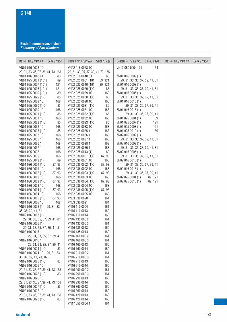
Bestell Nr. / Part No. Seite / Page Bestell Nr. / Part No. Seite / Page Bestell Nr. / Part No. Seite / Page Bestell Nr. / Part No. Seite / Page
Amphenol 173
C 146
BestellnummernverzeichnisSummary of Part Numbers
VN01 016 0028 1C29, 31, 33, 35, 37, 39, 41, 73, 168VN01 016 0040 8X 83VN01 025 0001 (101) 89VN01 025 0007 (101) 121VN01 025 0008 (101) 121VN01 025 0010 (101) 89VN01 025 0029 (1)C 85VN01 025 0029 1C 168VN01 025 0030 (1)C 85VN01 025 0030 1C 168VN01 025 0031 (1)C 85VN01 025 0031 1C 168VN01 025 0032 (1)C 85VN01 025 0032 1C 168VN01 025 0033 (1)C 85VN01 025 0033 1C 168VN01 025 0035 1 168VN01 025 0036 1 168VN01 025 0037 1 168VN01 025 0038 1 168VN01 025 0039 1 168VN01 025 0043 (1) 89VN01 036 0001 (1)C 87, 93VN01 036 0001 1C 168VN01 036 0002 (1)C 87, 93VN01 036 0002 1C 168VN01 036 0003 (1)C 87, 93VN01 036 0003 1C 168VN01 036 0004 (1)C 87, 93VN01 036 0004 1C 168VN01 036 0005 (1)C 87, 93VN01 036 0005 1C 168VN02 016 0002 (1) 29, 31, 33,35, 37, 39, 41, 81VN02 016 0003 (1)
29, 31, 33, 35, 37, 39, 41, 81VN02 016 0005 (1)
29, 31, 33, 35, 37, 39, 41, 81VN02 016 0015 1
29, 31, 33, 35, 37, 39, 41VN02 016 0016 1
29, 31, 33, 35, 37, 39, 41VN02 016 0024 (1)C 83VN02 016 0024 1C 29, 31, 33,35, 37, 39, 41, 73, 168VN02 016 0025 (1)C 83VN02 016 0025 1C29, 31, 33, 35, 37, 39, 41, 73, 168VN02 016 0026 (1)C 83VN02 016 0026 1C29, 31, 33, 35, 37, 39, 41, 73, 168VN02 016 0027 (1)C 83VN02 016 0027 1C29, 31, 33, 35, 37, 39, 41, 73, 168VN02 016 0028 (1)C 83
VN02 016 0028 1C29, 31, 33, 35, 37, 39, 41, 73, 168VN02 016 0040 8X 83VN02 025 0001 (101) 89, 121VN02 025 0010 (101) 89, 121VN02 025 0029 (1)C 85VN02 025 0029 1C 168VN02 025 0030 (1)C 85VN02 025 0030 1C 168VN02 025 0031 (1)C 85VN02 025 0031 1C 168VN02 025 0032 (1)C 85VN02 025 0032 1C 168VN02 025 0033 (1)C 85VN02 025 0033 1C 168VN02 025 0035 1 168VN02 025 0036 1 168VN02 025 0037 1 168VN02 025 0038 1 168VN02 025 0039 1 168VN02 025 0043 (1) 89VN02 036 0001 (1)C 87, 93VN02 036 0001 1C 168VN02 036 0002 (1)C 87, 93VN02 036 0002 1C 168VN02 036 0003 (1)C 87, 93VN02 036 0003 1C 168VN02 036 0004 (1)C 87, 93VN02 036 0004 1C 168VN02 036 0005 (1)C 87, 93VN02 036 0005 1C 168VN03 030 0020 164VN03 030 0021 164VN16 110 0004 161VN16 110 0013 160VN16 110 0014 160VN16 135 000 2 161VN16 135 000 3 161VN16 135 0013 160VN16 135 0014 160VN16 160 000 2 161VN16 160 000 3 161VN16 160 0013 160VN16 160 0014 160VN16 210 000 2 161VN16 210 000 3 161VN16 210 0013 160VN16 210 0014 160VN16 290 000 2 161VN16 290 000 3 161VN16 290 0013 160VN16 290 0014 160VN16 360 0013 160VN16 360 0014 160VN16 420 0013 160VN16 420 0014 160VN17 050 0004 1 164
VN17 050 0004 101 164
ZN01 016 0002 (1)29, 31, 33, 35, 37, 39, 41, 81
ZN01 016 0003 (1)29, 31, 33, 35, 37, 39, 41, 81
ZN01 016 0005 (1)29, 31, 33, 35, 37, 39, 41, 81
ZN01 016 0015 (1)29, 31, 33, 35, 37, 39, 41
ZN01 016 0016 (1)29, 31, 33, 35, 37, 39, 41
ZN01 025 0001 (1) 89ZN01 025 0007 (1) 121ZN01 025 0008 (1) 121ZN01 025 0010 (1) 89ZN02 016 0002 (1)
29, 31, 33, 35, 37, 39, 41, 81ZN02 016 0003 (1)
29, 31, 33, 35, 37, 39, 41, 81ZN02 016 0005 (1)
29, 31, 33, 35, 37, 39, 41, 81ZN02 016 0015 (1)
29, 31, 33, 35, 37, 39, 41ZN02 016 0016 (1)
29, 31, 33, 35, 37, 39, 41ZN02 025 0001 (1) 89, 121ZN02 025 0010 (1) 89, 121
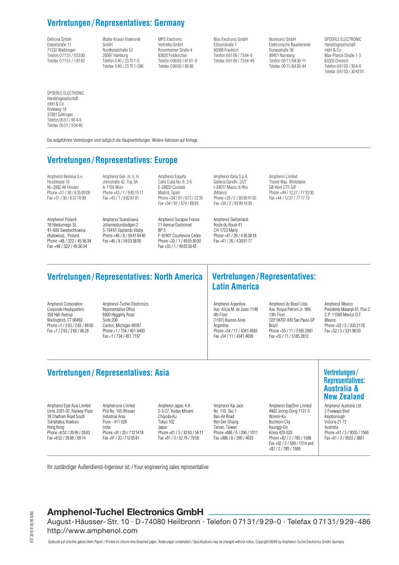
Vertretungen / Representatives: Germany
Vertretungen / Representatives: Europe
Deltrona GmbHDieselstraße 1171332 WaiblingenTelefon 0 71 51 / 9 53 00Telefax 0 71 51 / 1 81 62
Walter Kluxen ElektronikGmbHNordkanalstraße 5220097 Hamburg Telefon 0 40 / 23 70 1-0Telefax 0 40 / 23 70 1-596
MPS ElectronicVertriebs GmbHRosenheimer Straße 483620 FeldkirchenTelefon 0 80 63 / 81 01-0Telefax 0 80 63 / 86 86
Nies Electronic GmbHEdisonstraße 760388 Frankfurt Telefon 0 61 09 / 73 64-0Telefax 0 61 09 / 73 64-49
Novitronic GmbHElektronische BauelementeDonaustraße 3690451 NürnbergTelefon 09 11/64 30-11Telefax 09 11/64 30-44
SPOERLE ELECTRONICHandelsgesellschaftmbH & Co.Max-Planck-Straße 1-363303 Dreieich Telefon 0 61 03 / 30 4-0Telefax 0 61 03 / 30 42 01
SPOERLE ELECTRONICHandelsgesellschaftmbH & Co.Rodeweg 1837081 GöttingenTelefon 05 51 / 90 4-0Telefax 05 51 / 9 04 46
Amphenol Benelux b.v.Hoofdveste 19NL-3992 AK HoutenPhone +31 / 30 / 6 35 80 00Fax +31 / 30 / 6 37 78 99
Amphenol Ges. m. b. H.Johnstraße 42, Top 3AA-1150 WienPhone +43 / 1 / 9 85 15 11Fax +43 / 1 / 9 82 61 01
Amphenol EspañaCalle Cuba No. 6, 2-5E-28820 CosladaMadrid, SpainPhone +34 / 91 / 673 / 22 35Fax +34 / 91 / 674 / 08 93
Amphenol Italia S.p.A.Galleria Gandhi, 2/27I-20017 Mazzo di Rho(Milano)Phone +39 / 2 / 93 90 41 92Fax +39 / 2 / 93 90 10 30
Amphenol LimitedThanet Way, WhitstableGB-Kent CT5 3JFPhone +44 / 12 27 / 77 32 00Fax +44 / 12 27 / 77 17 73
Vertretungen / Representatives: North America
Amphenol CorporationCorporate Headquarters358 Hall AvenueWallingford, CT 06492Phone +1 / 2 03 / 2 65 / 89 00Fax +1 / 2 03 / 2 65 / 86 28
Amphenol-Tuchel ElectronicsRepresentative Office6900 Haggerty RoadSuite 200Canton, Michigan 48187Phone +1 / 734 / 451 6400Fax +1 / 734 / 451 7197
Amphenol ArgentinaAve. Alicia M. de Justo 11484th Floor(1107) Buenos AiresArgentinaPhone +54 / 11 / 4341.4565Fax +54 / 11 / 4341.4699
Amphenol do Brasil Ltda.Ave. Roque Petroni Jr. 999,13th FloorCEP 04707-910 Sao Paulo-SPBrazilPhone +55 / 11 / 5185.2881Fax +55 / 11 / 5185.2812
Amphenol MexicoPresidente Masaryk 61, Piso 2C.P. 11560 Mexico D.F.MexicoPhone +52 / 5 / 203.2178Fax +52 / 5 / 531.96 59
Amphenol Poland18 Niedurnego St.41-600 Swietochlowice(Katowice), Poland.Phone +48 / 322 / 45 36 34Fax +48 / 322 / 45 36 34
Amphenol Scandinavia Johanneslundsvägen 2S-194 61 Upplands VäsbyPhone +46 / 8 / 59 41 04 40Fax +46 / 8 / 59 03 38 00
Amphenol Socapex France11 Avenue DurbonnetBP 5F-92407 Courbevoie CedexPhone +33 / 1 / 49 05 30 00Fax +33 / 1 / 49 05 30 43
Amphenol SwitzerlandRoute du Roule 41CH-1723 MarlyPhone +41 / 26 / 4 36 38 18Fax +41 / 26 / 4 30 01 77
Ihr zuständiger Außendienst-Ingenieur ist: / Your engineering sales representative:
Amphenol East Asia LimitedUnits 2201-02, Railway Plaza39 Chatham Road SouthTsimshatsui, KowloonHong KongPhone +8 52 / 26 99 / 26 63Fax +8 52 / 26 88 / 09 74
Amphetronix LimitedPlot No. 105 BhosariIndustrial AreaPune - 411 026IndiaPhone +91 / 20 / 7121418Fax +91 / 20 / 712 05 81
Amphenol Japan, K.K.2-3-27, Kudan MinamiChiyoda-KuTokyo 102JapanPhone +81 / 3 / 32 63 / 56 11Fax +81 / 3 / 52 76 / 70 59
Amphenol Kai JackNo. 110, Sec 1Bao-An RoadRen-Der ShiangTainan, TaiwanPhone +886 / 6 / 266 / 1011Fax +886 / 6 / 266 / 4633
Amphenol DaeShin Limited#802 Joong-Dong 1131-5Wonmi-KuBucheon-CityKyunggi-DoKorea 420-020Phone +82 / 2 / 785 / 1588Fax +82 / 2 / 589 / 1514 and+82 / 2 / 785 / 1589
Amphenol Australia Ltd.2 Fiveways BlvdKeysboroughVictoria 21 73AustraliaPhone +61 / 3 / 9555 / 1566Fax +61 / 3 / 9553 / 3801
Die aufgeführten Vertretungen sind lediglich die Hauptvertretungen. Weitere Adressen auf Anfrage.
ATE
3010
B 0
8.99
500
0
Gedruckt auf chlorfrei gebleichtem Papier / Printed on chlorin-free bleached paper, Änderungen vorbehalten / Specifications may be changed without notice, Copyright 08/99 by Amphenol-Tuchel Electronics GmbH, Germany
Vertretungen / Representatives: Asia
Vertretungen / Representatives:Latin America
Amphenol-Tuchel Electronics GmbHAugust-Häusser- Str. 10 . D-74080 Heilbronn . Telefon 0 7131/9 29-0 . Telefax 0 7131/9 29-486http://www.amphenol.com
Vertretungen /Representatives:Australia &New Zealand