Embed Size (px)
Citation preview
Leitlinie für die europäische technische Zulassung (ETAG)
ETAG 004
AUSSENSEITIGE WÄRMEDÄMMVERBUNDSYSTEME MIT
PUTZSCHICHT
Ausgabe 2000 Änderungen 2011 und 2013
OIB-467-013/13
Vorbemerkungen zur Leitlinie für die europäische technische Zulassung für
AUSSENSEITIGE WÄRMEDÄMMVERBUNDSYSTEME MIT PUTZSCHICHT
Vorbemerkungen
Leitlinien für die europäische technische Zulassung wurden aufgrund eines von der Kommission der Europäischen Gemeinschaften nach Art. 11 Abs. 1 der Richtlinie des Rates vom 21. Dezember 1988 zur Angleichung der Rechts- und Verwaltungsvorschriften der Mitgliedstaaten über Bauprodukte (89/106/EWG) (Bauproduktenrichtlinie) erteilten Auftrages vom Gremium der von den Mitgliedstaaten bestimmten Zulassungsstellen (EOTA) erarbeitet.
Leitlinien für die europäische technische Zulassung können von Technischen Bewertungsstellen gemäß Art. 66 Abs. 3 der Verordnung (EU) Nr. 305/2011 (Bauproduktenverordnung) als Europäisches Bewertungsdokument verwendet werden. Leitlinien sind damit die Grundlage für Europäische Technische Bewertungen.
In Zweifelsfällen bzw. in Fällen von Übersetzungsfehlern ist die im EOTA-Sekretariat (Kunstlaan 40, Avenue des Arts, 1040 Bruxelles, Belgien) vorliegende Originalfassung der Leitlinie maßgebend.
Stand, August 2013
European Organisation for Technical Approvals Europäische Organisation für Technische Zulassungen Organisation Européenne pour l’Agrément Technique
ETAG 004 Edition 2000
Amended August 2011
Amended February 2013
GUIDELINE FOR EUROPEAN TECHNICAL APPROVAL
of
EXTERNAL THERMAL INSULATION
COMPOSITE SYSTEMS (ETICS) WITH RENDERING
Copyright © 2013 EOTA
E O T A Kunstlaan 40 Avenue des Arts
B - 1040 BRUSSELS
TABLE OF CONTENTS Section one: INTRODUCTON
Pages
FOREWORD 10
Background of the ETAG 10
Reference documents 10
Updating conditions 13
1 PRELIMINARIES 14
1.1 LEGAL BASIS 14
1.2 STATUS OF ETA-GUIDELINES 14
2 SCOPE 16
2.1 SCOPE 16
2.2 USE CATEGORIES, PRODUCTS FAMILIES, KITS AND SYSTEMS 16
2.3 ASSUMPTIONS 17
3 TERMINOLOGY 18
3.1 COMMON TERMINOLOGY AND ABBREVIATIONS 18
3.2 SPECIFIC TERMINOLOGY 18
3.2.1 Substrates 18
3.2.2 ETICS components 18
3.2.2.1 Adhesive 18
3.2.2.2 Insulation product 18
3.2.2.3 Rendering system 18
3.2.2.4 Mechanical fixing devices 19
3.2.2.5 Ancillary materials 19
3.2.3 ETICS description 19
3.2.3.1 Bonded ETICS 19
3.2.3.2 Mechanically fixed ETICS 19
3.2.3.3 ETICS kit 19
Section two : GUIDANCE FOR THE ASSESSMENT OF THE FITNESS FOR USE
GENERAL NOTES 20
4 REQUIREMENTS 22
4.0 GENERAL 22
4.1 ER1 : MECHANICAL RESISTANCE AND STABILITY 24
4.2 ER2 : SAFETY IN CASE OF FIRE 24
4.3 ER3 : HYGIENE, HEALTH AND ENVIRONMENT 24
4.3.1 Indoor environment, dampness 24
4.3.2 Outdoor environment 25
4.3.3 Release of dangerous substances 25
4.4 ER4 : SAFETY IN USE 25
4.5 ER5 : PROTECTION AGAINST NOISE 26
4.6 ER6 : ENERGY ECONOMY AND HEAT RETENTION 26
Page 2/143 ©EOTA_ETAG 004, February 2013
4.7 ASPECTS OF DURABILITY AND SERVICEABILITY 26
5 METHODS OF VERIFICATION 28
5.0 GENERAL 28
5.1 TEST ON THE ETICS 30
5.1.1 Mechanical resistance and stability 30
5.1.2 Safety in case of fire 30
5.1.2.1 Reaction to fire 30
5.1.3 Hygiene, health and the environment 31
5.1.3.1 Water absorption (capillarity test) 31
5.1.3.2 Watertightness 32
5.1.3.2.1 Hygrothermal behaviour 32
5.1.3.2.2 Freeze-thaw behaviour 36
5.1.3.3 Impact resistance 37
5.1.3.4 Water vapour permeability (resistance to water vapour diffusion) 37
5.1.3.5 Release of dangerous substances 38
5.1.4 Safety in use 39
5.1.4.1 Bond strength 40
5.1.4.1.1 Bond strength between base coat and insulation product 40
5.1.4.1.2 Bond strength test between adhesive (mortar or paste) and substrate 41
5.1.4.1.3 Bond strength test between adhesive (mortar or paste) and insulation product 41
5.1.4.1.4 Bond strength of foam adhesives 42
5.1.4.2 Fixing strength (transverse displacement) 42
5.1.4.2.1 Displacement test 42
5.1.4.3 Wind load resistance of mechanically fixed ETICS 45
5.1.4.3.1 Pull-through tests of fixings 46
5.1.4.3.2 Static foam block test 47
5.1.4.3.3 Dynamic wind uplift test 48
5.1.5 Protection against noise 52
5.1.5.1 Airborne sound insulation 52
5.1.6 Energy economy and heat retention 52
5.1.6.1 Thermal resistance and thermal transmittance 52
5.1.7 Aspects of durability and serviceability 54
5.1.7.1 Bond strength after ageing 54
5.1.7.1.1 Finishing coat tested on the rig 54
5.1.7.1.2 Finishing coat not tested on the rig 54
TEST ON COMPONENTS 55
5.2 INSULATION PRODUCT 55
5.2.1 Mechanical resistance and stability 55
5.2.2 Safety in case of fire 55
5.2.3 Hygiene, health and the environment 55
5.2.3.1 Water absorption 55
5.2.3.2 Water vapour permeability 55
5.2.4 Safety in use 55
5.2.4.1 Tensile test perpendicular to the faces 56
5.2.4.1.1 In dry conditions 56
5.2.4.1.2 In wet conditions 56
5.2.4.2 Shear strength and shear modulus of elasticity test 56
5.2.5 Protection against noise 56
5.2.6 Energy economy and heat retention 57
Page 3/143 ©EOTA_ETAG 004, February 2013
5.2.6.1 Thermal resistance 57
5.3 ANCHORS 57
5.3.1 Mechanical resistance and stability 57
5.3.2 Safety in case of fire 57
5.3.3 Hygiene, health and the environment 57
5.3.4 Safety in use 57
5.3.4.1 Pull-out strength of anchor 57
5.3.5 Protection against noise 57
5.3.6 Energy economy and heat retention 57
5.4 PROFILES AND THEIR FIXINGS 57
5.4.1 Mechanical resistance and stability 57
5.4.2 Safety in case of fire 57
5.4.3 Hygiene, health and the environment 57
5.4.4 Safety in use 58
5.4.4.1 Pull-through resistance of fixings from profiles 58
5.4.5 Protection against noise 58
5.4.6 Energy economy and heat retention 58
5.5 Render 58
5.5.1 Mechanical resistance and stability 58
5.5.2 Safety in case of fire 59
5.5.3 Hygiene, health and the environment 59
5.5.4 Safety in use 59
5.5.4.1 Render Strip Tensile Test 59
5.5.5 Protection against noise 62
5.5.6 Energy economy and heat retention 62
5.6 REINFORCEMENT 62
5.6.1 Mechanical resistance and stability 62
5.6.2 Safety in case of fire 62
5.6.3 Hygiene, health and the environment 62
5.6.4 Safety in use 62
5.6.5 Protection against noise 62
5.6.6 Energy economy and heat retention 62
5.6.7 Aspects of durability and serviceability 63
5.6.7.1 Glass fibre mesh – Tensile strength and elongation of the reinforcing fabric 63
5.6.7.1.1 Testing in the as-delivered state 63
5.6.7.1.2 Testing after ageing 63
5.6.7.2 Metal lath or mesh 64
5.6.7.3 Other reinforcements 64
5.7 Foam adhesives 64
5.7.1 Mechanical resistance and stability 64
5.7.2 Safety in case of fire 64
5.7.3 Hygiene, health and the environment 64
5.7.4 Safety in use 64
5.7.4.1 Shear strength and shear modulus 64
5.7.4.1 Post expansion behaviour 64
5.7.5 Protection against noise 64
5.7.6 Energy economy and heat retention 64
6 ASSESSING AND JUDGING THE FITNESS FOR USE 65
6.0 GENERAL 65
Page 4/143 ©EOTA_ETAG 004, February 2013
6.1 ETICS 67
6.1.1 Mechanical resistance and stability 67
6.1.2 Safety in case of fire 67
6.1.2.1 Reaction to fire 67
6.1.3 Hygiene, health and the environment 67
6.1.3.1 Water absorption (capillarity test) 67
6.1.3.2 Watertightness 67
6.1.3.2.1 Hygrothermal performance 67
6.1.3.2.2 Freeze-thaw performance 68
6.1.3.3 Impact resistance 68
6.1.3.4 Water vapour permeability 69
6.1.3.5 Release of dangerous substances 69
6.1.4 Safety in use 70
6.1.4.1 Bond strength 70
6.1.4.1.1 Bond strength between base coat and insulation product 70
6.1.4.1.2 Bond strength between adhesive and substrate 70
6.1.4.1.3 Bond strength between adhesive and insulation product 70
6.1.4.1.4 Bond strength of foam adhesives 71
6.1.4.2 Fixing strength (transverse displacement) 71
6.1.4.2.1 Displacement test 71
6.1.4.3 Wind load resistance of mechanically fixed ETICS 71
6.1.4.3.1 Pull-through of fixings 71
6.1.4.3.2 Static foam block test 72
6.1.4.3.3 Dynamic wind uplift test 72
6.1.5 Protection against noise 72
6.1.5.1 Airborne sound insulation 72
6.1.6 Energy economy and heat retention 73
6.1.6.1 Thermal resistance 73
6.1.7 Aspects of durability and serviceability 73
6.1.7.1 Bond strength after ageing 73
TEST ON COMPONENTS 73
6.2 INSULATION PRODUCT 73
6.2.1 Mechanical resistance and stability 73
6.2.2 Safety in case of fire 73
6.2.3 Hygiene, health and the environment 73
6.2.3.1 Water absorption 73
6.2.3.2 Water vapour permeability 74
6.2.4 Safety in use 74
6.2.4.1 Tensile strength perpendicular to the faces 74
6.2.4.2 Shear strength and shear modulus of elasticity 74
6.2.5 Protection against noise 74
6.2.6 Energy economy and heat retention 74
6.2.6.1 Thermal resistance 74
6.3 ANCHORS 75
6.3.1 Mechanical resistance and stability 75
6.3.2 Safety in case of fire 75
6.3.3 Hygiene, health and the environment 75
6.3.4 Safety in use 75
6.3.4.1 Pull-out strength of anchor 75
6.3.5 Protection against noise 75
6.3.6 Energy economy and heat retention 75
Page 5/143 ©EOTA_ETAG 004, February 2013

6.4 PROFILES AND THEIR FIXINGS 75
6.4.1 Mechanical resistance and stability 75
6.4.2 Safety in case of fire 75
6.4.3 Hygiene, health and the environment 75
6.4.4 Safety in use 76
6.4.4.1 Pull-through resistance of fixings from profiles 76
6.4.5 Protection against noise 76
6.4.6 Energy economy and heat retention 76
6.5 RENDER 76
6.5.1 Mechanical resistance and stability 76
6.5.2 Safety in case of fire 76
6.5.3 Hygiene, health and the environment 76
6.5.4 Safety in use 76
6.5.4.1 Render Strip Tensile Test 76
6.5.5 Protection against noise 76
6.5.6 Energy economy and heat retention 76
6.6 REINFORCEMENT 76
6.6.1 Mechanical resistance and stability 76
6.6.2 Safety in case of fire 77
6.6.3 Hygiene, health and the environment 77
6.6.4 Safety in use 77
6.6.5 Protection against noise 77
6.6.6 Energy economy and heat retention 77
6.6.7 Aspects of durability and serviceability 77
6.6.7.1 Glass fibre mesh – Tensile strength and elongation of the reinforcing fabric 77
6.6.7.2 Metal lath or mesh 77
6.6.7.3 Other reinforcements 77
6.7 Foam adhesives 77
6.7.1 Mechanical resistance and stability 77
6.7.2 Safety in case of fire 77
6.7.3 Hygiene, health and the environment 77
6.7.4 Safety in use 78
5.7.4.1 Shear strength and shear modulus 78
5.7.4.1 Post expansion behaviour 78
6.7.5 Protection against noise 78
6.7.6 Energy economy and heat retention 78
7 ASSUMPTIONS AND RECOMMENDATIONS UNDER WHICH THE FITNESS FOR USE OF THE PRODUCT IS ASSESSED 79
7.0 GENERAL 79
7.1 DESIGN OF THE WORKS 79
7.1.1 Substrate inspection 79
7.1.2 ETICS design 79
7.1.2.1 Mechanical resistance and stability 79
7.1.2.2 Safety in case of fire 79
7.1.2.3 Hygiene, health and the environment 80
7.1.2.4 Safety in use 80
7.1.2.5 Protection against noise 80
7.1.2.6 Energy economy and heat retention 81
7.1.2.7 Aspects of durability and serviceability 81
Page 6/143 ©EOTA_ETAG 004, February 2013
7.2 EXECUTION OF THE WORKS 81
7.2.1 Preparation of the substrate 81
7.2.2 Basic principles of ETICS installation 81
7.3 MAINTENANCE AND REPAIR OF THE WORKS 82
Section three : ATTESTATION OF CONFORMITY
8 ATTESTATION AND EVALUATION OF CONFORMITY 83
8.1 EC DECISIONS 83
8.2 TASKS AND RESPONSIBILITIES OF THE MANUFACTURER AND NOTIFIED BODIES 84
8.2.1 Tasks of the manufacturer 84
8.2.1.1 Factory production control 84
8.2.1.2 Testing of samples taken at the factory 84
8.2.1.3 Declaration of Conformity 84
8.2.2 Tasks of the manufacturer or the approved Notified Body 84
8.2.2.1 Initial Type Testing 84
8.2.3 Tasks of the approved Notified Body 85
8.2.3.1 Assessment of the factory production control system - initial inspection and continuous surveillance 85
8.2.3.2 Certification 85
8.3 DOCUMENTATION 85
Section four : ETA CONTENT
9 THE ETA CONTENT 89
9.1 THE ETA CONTENT 89
ANNEXES
Annex A : COMMON TERMINOLOGY AND ABBREVIATIONS 90
A.1 Works and products 90
A.1.1 Construction works 90
A.1.2 Construction products 90
A.1.3 Incorporation 90
A.1.4 Intended use 90
A.1.5 Execution 90
A.1.6 System 90
A.2 Performances 91
A.2.1 Fitness for Intended use 91
A.2.2 Serviceability 91
A.2.3 Essential Requirements 91
A.2.4 Performance 91
A.2.5 Actions 91
A.2.6 Classes or levels 91
A.3 ETAG – Format 92
A.3.1 Requirements 92
A.3.2 Methods of verification 92
A.3.3 Specifications 92
A.4 Working life 92
A.4.1 Working life (of works or parts of the works) 92
Page 7/143 ©EOTA_ETAG 004, February 2013
A.4.2 Working life (of products) 93
A.4.3 Economically reasonable working life 93
A.4.4 Maintenance 93
A.4.5 Normal maintenance 93
A.4.6 Durability 93
A.5 Conformity 93
A.5.1 Attestation of conformity 93
A.5.2 Identification 93
A.6 Approval and Notified Body 93
A.6.1 Approval Body 93
A.6.2 Notified Body 93
A.7 Abbreviations 94
A.7.1 Abbreviations concerning the Construction products directive 94
A.7.2 Abbreviations concerning approval 94
A.7.3 General abbreviations 94
Annex B : SYNOPSIS 95
Annex C : METHODS RELATED TO THE IDENTIFICATION OF THE ETICS COMPONENTS 96
C.1 Adhesives, base coats, key coats and finishing coats 96
C.1.1 Products as delivered 96
C.1.1.1 Density 96
C.1.1.2 Dry extract 96
C.1.1.2.1 Lime and polymer based products 97
C.1.1.2.2 Silicate based products 97
C.1.1.3 Ash content 97
C.1.1.4 Particle size grading 97
C.1.2 Fresh mortar 98
C.1.2.0 Preparation of mortar 98
C.1.2.0.1 Dry mortar 98
C.1.2.0.2 Paste requiring addition of cement and powder requiringaddition of extra binder 98
C.1.2.0.3 Ready to use paste 98
C.1.2.1 Water retention capability 98
C.1.2.2 Density of fresh mortar 100
C.1.3 Hardened base coat 100
C.1.3.1 Products with a thickness greater than 5 mm 100
C.1.3.1.0 Preparation and storing of test samples 100
C.1.3.1.1 Dynamic modulus of elasticity 100
C.1.3.1.2 Shrinkage test 102
C.1.3.2 Products with a thickness up to 5 mm : static modulus of elasticity, tensile strength and elongation at break 102
C.2 Insulation product 102
C.2.1 Density measurement 102
C.2.2 Dimensional characteristics and appearance 103
C.2.2.1 Length and width 103
C.2.2.2 Thickness 103
C.2.2.3 Squareness 103
C.2.2.4 Flatness 103
C.2.2.5 Surface condition 103
C.2.3 Compression test 103
C.2.4 Dimensional stability tests 103
Page 8/143 ©EOTA_ETAG 004, February 2013
C.3 Reinforcement 103
C.3.1 Mass per unit area 103
C.3.2 Ash content 103
C.3.3 Mesh size and number of filaments 104
C.3.4 Elongation 104
C.4 Mechanical fixing devices 104
C.4.1 Dimensions 104
C.4.2 Load characteristics if necessary 104
Annex D : REACTION TO FIRE 105
D.1 General 106
D.2 Testing according to EN ISO 1182 106
D.2.1 insulation product 106
D.2.2 Render coatings 106
D.2.2.1 Base coats and finishing coats 106
D.2.2.2 Key coats and decorative coats 106
D.2.3 Adhesive 106
D.2.4 Reinforcement 106
D.3 Testing according to EN ISO 1716 106
D.3.1 Insulation product 107
D.3.2 Render coating 107
D.3.3 Adhesive 107
D.3.4 Reinforcement 107
D.4 Testing according to EN 13823 107
D.4.1 Insulation product 108
D.4.2 Render coatings 108
D.4.3 Adhesive 109
D.4.4 Reinforcement 109
D.4.5 Application of test results 109
D.5 Testing according to EN ISO 11925-2 110
D.5.1 Insulation product 110
D.5.2 Render coatings 110
D.5.3 Adhesive 110
D.5.4 Reinforcement 111
D.5.5 Application of test results 111
Annex E : ETA MODEL 114
Page 9/143 ©EOTA_ETAG 004, February 2013
FOREWORD
Background of the ETAG
This Guideline has been drawn up by the EOTA Working Group 04.04/11 - External Thermal Insulation Composite Systems (ETICS).
The WG consisted of members from fourteen EU-countries (Austria, Belgium, Czech Republic (Convenor since 2008), Denmark, Finland, France (Convenor until 2007), Germany, Italy, Netherlands, Lithuania, Portugal, Slovak Republic, Slovenia and the United Kingdom) and five European industrial organisations (EEWISA (European External Wall Insulation Systems Association), EMO (European Mortars Organisation), EUMEPS (European Manufacturers of Expanded Polystyrene), EURIMA (European Insulation Manufacturers Association) and EAE (European Association for ETICS).
The Guideline sets out the performance requirements for External Thermal Insulation Composite Systems (ETICS) for the use as external insulation of building walls, the verification methods used to examine the various aspects of performance, the assessment criteria used to judge the performance for the intended use and the presumed conditions for the design and execution.
The UEAtc Directives for the Assessment of External Insulation Systems for Walls (Expanded Polystyrene Insulation Faced with a Thin Rendering), June 1988 and UEAtc Technical Guide for the Assessment of External Wall Insulation Systems Faced with Mineral Render, April 1992 have formed part of the basis for the Guideline.
Reference documents
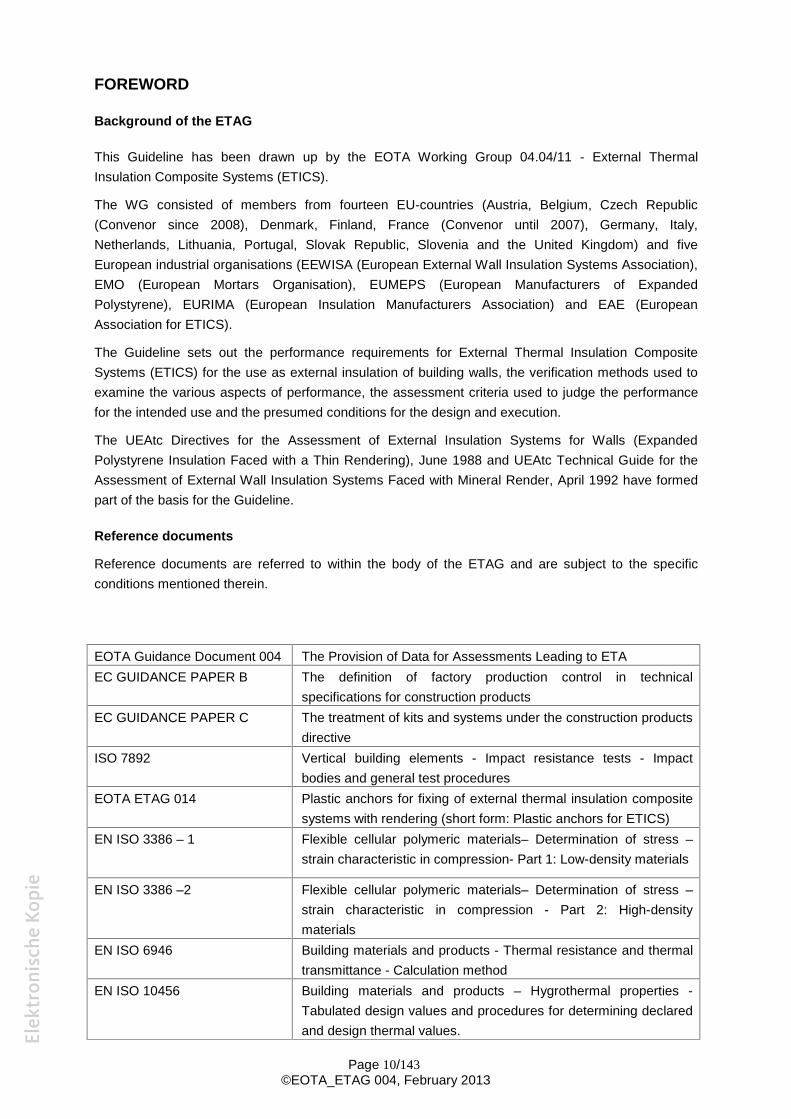
Reference documents are referred to within the body of the ETAG and are subject to the specific conditions mentioned therein.
EOTA Guidance Document 004 The Provision of Data for Assessments Leading to ETA EC GUIDANCE PAPER B The definition of factory production control in technical
specifications for construction products EC GUIDANCE PAPER C The treatment of kits and systems under the construction products
directive ISO 7892 Vertical building elements - Impact resistance tests - Impact
bodies and general test procedures EOTA ETAG 014 Plastic anchors for fixing of external thermal insulation composite
systems with rendering (short form: Plastic anchors for ETICS) EN ISO 3386 – 1 Flexible cellular polymeric materials– Determination of stress –
strain characteristic in compression- Part 1: Low-density materials
EN ISO 3386 –2 Flexible cellular polymeric materials– Determination of stress – strain characteristic in compression - Part 2: High-density materials
EN ISO 6946 Building materials and products - Thermal resistance and thermal transmittance - Calculation method
EN ISO 10456 Building materials and products – Hygrothermal properties -Tabulated design values and procedures for determining declared and design thermal values.
Page 10/143 ©EOTA_ETAG 004, February 2013
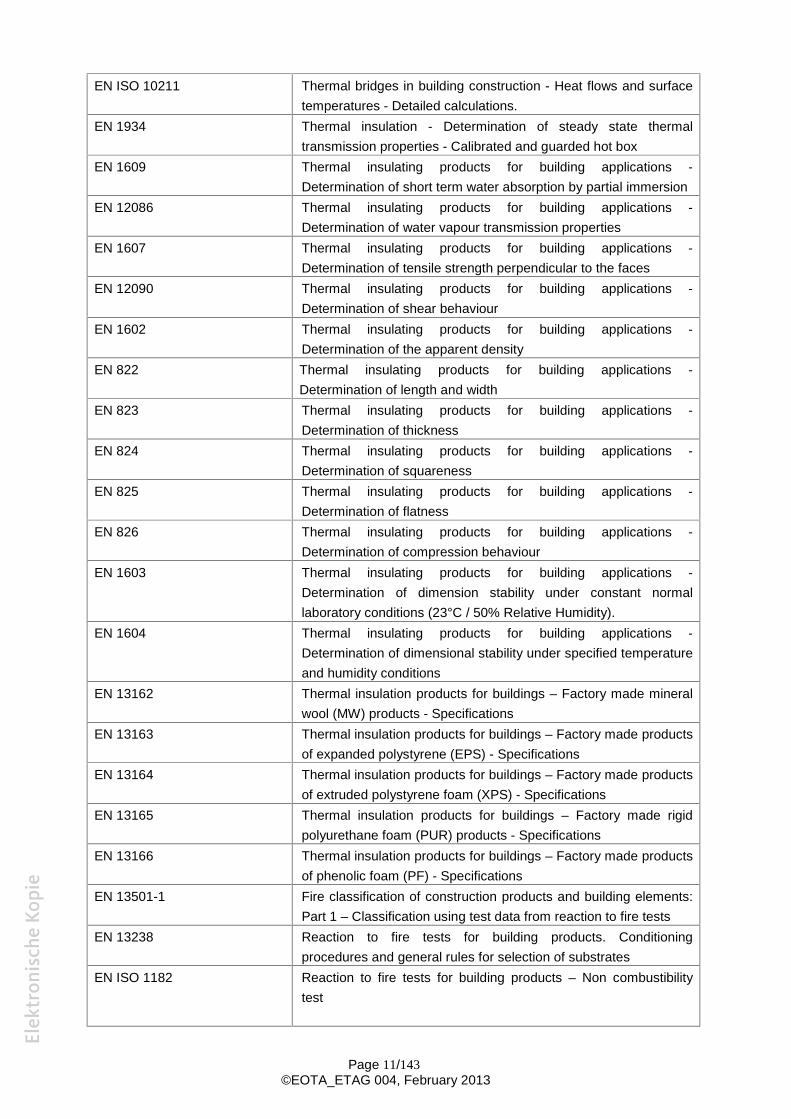
EN ISO 10211 Thermal bridges in building construction - Heat flows and surface temperatures - Detailed calculations.
EN 1934 Thermal insulation - Determination of steady state thermal transmission properties - Calibrated and guarded hot box
EN 1609 Thermal insulating products for building applications -Determination of short term water absorption by partial immersion
EN 12086 Thermal insulating products for building applications -Determination of water vapour transmission properties
EN 1607 Thermal insulating products for building applications -Determination of tensile strength perpendicular to the faces
EN 12090 Thermal insulating products for building applications -Determination of shear behaviour
EN 1602 Thermal insulating products for building applications -Determination of the apparent density
EN 822 Thermal insulating products for building applications -Determination of length and width
EN 823 Thermal insulating products for building applications -Determination of thickness
EN 824 Thermal insulating products for building applications -Determination of squareness
EN 825 Thermal insulating products for building applications -Determination of flatness
EN 826 Thermal insulating products for building applications -Determination of compression behaviour
EN 1603 Thermal insulating products for building applications -Determination of dimension stability under constant normal laboratory conditions (23°C / 50% Relative Humidity).
EN 1604 Thermal insulating products for building applications -Determination of dimensional stability under specified temperature and humidity conditions
EN 13162 Thermal insulation products for buildings – Factory made mineral wool (MW) products - Specifications
EN 13163 Thermal insulation products for buildings – Factory made products of expanded polystyrene (EPS) - Specifications
EN 13164 Thermal insulation products for buildings – Factory made products of extruded polystyrene foam (XPS) - Specifications
EN 13165 Thermal insulation products for buildings – Factory made rigid polyurethane foam (PUR) products - Specifications
EN 13166 Thermal insulation products for buildings – Factory made products of phenolic foam (PF) - Specifications
EN 13501-1 Fire classification of construction products and building elements: Part 1 – Classification using test data from reaction to fire tests
EN 13238 Reaction to fire tests for building products. Conditioning procedures and general rules for selection of substrates
EN ISO 1182 Reaction to fire tests for building products – Non combustibility test
Page 11/143 ©EOTA_ETAG 004, February 2013
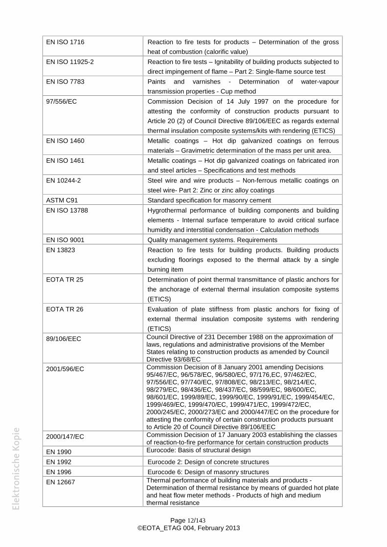
EN ISO 1716 Reaction to fire tests for products – Determination of the gross heat of combustion (calorific value)
EN ISO 11925-2 Reaction to fire tests – Ignitability of building products subjected to direct impingement of flame – Part 2: Single-flame source test
EN ISO 7783 Paints and varnishes - Determination of water-vapour transmission properties - Cup method
97/556/EC Commission Decision of 14 July 1997 on the procedure for attesting the conformity of construction products pursuant to Article 20 (2) of Council Directive 89/106/EEC as regards external thermal insulation composite systems/kits with rendering (ETICS)
EN ISO 1460 Metallic coatings – Hot dip galvanized coatings on ferrous materials – Gravimetric determination of the mass per unit area.
EN ISO 1461 Metallic coatings – Hot dip galvanized coatings on fabricated iron and steel articles – Specifications and test methods
EN 10244-2 Steel wire and wire products – Non-ferrous metallic coatings on steel wire- Part 2: Zinc or zinc alloy coatings
ASTM C91 Standard specification for masonry cement EN ISO 13788 Hygrothermal performance of building components and building
elements - Internal surface temperature to avoid critical surface humidity and interstitial condensation - Calculation methods
EN ISO 9001 Quality management systems. Requirements EN 13823 Reaction to fire tests for building products. Building products
excluding floorings exposed to the thermal attack by a single burning item
EOTA TR 25 Determination of point thermal transmittance of plastic anchors for the anchorage of external thermal insulation composite systems (ETICS)
EOTA TR 26 Evaluation of plate stiffness from plastic anchors for fixing of external thermal insulation composite systems with rendering (ETICS)
89/106/EEC Council Directive of 231 December 1988 on the approximation of laws, regulations and administrative provisions of the Member States relating to construction products as amended by Council Directive 93/68/EC
2001/596/EC Commission Decision of 8 January 2001 amending Decisions 95/467/EC, 96/578/EC, 96/580/EC, 97/176,EC, 97/462/EC, 97/556/EC, 97/740/EC, 97/808/EC, 98/213/EC, 98/214/EC, 98/279/EC, 98/436/EC, 98/437/EC, 98/599/EC, 98/600/EC, 98/601/EC, 1999/89/EC, 1999/90/EC, 1999/91/EC, 1999/454/EC, 1999/469/EC, 1999/470/EC, 1999/471/EC, 1999/472/EC, 2000/245/EC, 2000/273/EC and 2000/447/EC on the procedure for attesting the conformity of certain construction products pursuant to Article 20 of Council Directive 89/106/EEC
2000/147/EC Commission Decision of 17 January 2003 establishing the classes of reaction-to-fire performance for certain construction products
EN 1990 Eurocode: Basis of structural design
EN 1992 Eurocode 2: Design of concrete structures EN 1996 Eurocode 6: Design of masonry structures EN 12667 Thermal performance of building materials and products -
Determination of thermal resistance by means of guarded hot plate and heat flow meter methods - Products of high and medium thermal resistance
Page 12/143 ©EOTA_ETAG 004, February 2013
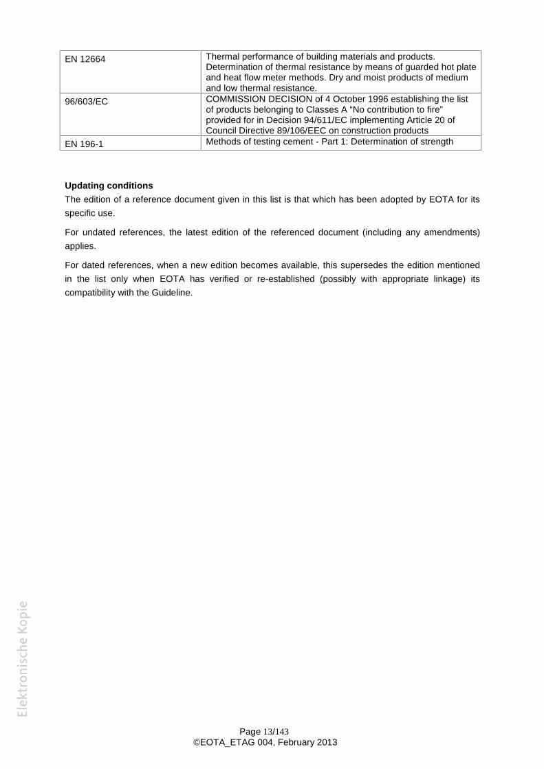
EN 12664 Thermal performance of building materials and products. Determination of thermal resistance by means of guarded hot plate and heat flow meter methods. Dry and moist products of medium and low thermal resistance.
96/603/EC COMMISSION DECISION of 4 October 1996 establishing the list of products belonging to Classes A “No contribution to fire” provided for in Decision 94/611/EC implementing Article 20 of Council Directive 89/106/EEC on construction products
EN 196-1 Methods of testing cement - Part 1: Determination of strength
Updating conditions The edition of a reference document given in this list is that which has been adopted by EOTA for its specific use.
For undated references, the latest edition of the referenced document (including any amendments) applies.
For dated references, when a new edition becomes available, this supersedes the edition mentioned in the list only when EOTA has verified or re-established (possibly with appropriate linkage) its compatibility with the Guideline.
Page 13/143 ©EOTA_ETAG 004, February 2013
S e c t i o n o n e : I N T R O D U C T I O N
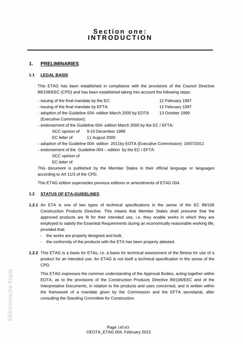
1. PRELIMINARIES
1.1 LEGAL BASIS
This ETAG has been established in compliance with the provisions of the Council Directive 89/106/EEC (CPD) and has been established taking into account the following steps:
- issuing of the final mandate by the EC: 12 February 1997
- issuing of the final mandate by EFTA: 12 February 1997
- adoption of the Guideline 004- edition March 2000 by EOTA 13 October 1999
(Executive Commission): - endorsement of the Guideline 004- edition March 2000 by the EC / EFTA:
SCC opinion of 9-10 December 1999
EC letter of 11 August 2000
- adoption of the Guideline 004- edition 2011by EOTA (Executive Commission): 19/07/2011 - endorsement of the Guideline 004 – edition by the EC / EFTA:
SCC opinion of EC letter of
This document is published by the Member States in their official language or languages according to Art 11/3 of the CPD.
This ETAG edition supersedes previous editions or amendments of ETAG 004.
1.2 STATUS OF ETA-GUIDELINES
1.2.1 An ETA is one of two types of technical specifications in the sense of the EC 89/106 Construction Products Directive. This means that Member States shall presume that the approved products are fit for their intended use, i.e. they enable works in which they are employed to satisfy the Essential Requirements during an economically reasonable working life, provided that: - the works are properly designed and built, - the conformity of the products with the ETA has been properly attested.
1.2.2 This ETAG is a basis for ETAs, i.e. a basis for technical assessment of the fitness for use of a product for an intended use. An ETAG is not itself a technical specification in the sense of the CPD.
This ETAG expresses the common understanding of the Approval Bodies, acting together within EOTA, as to the provisions of the Construction Products Directive 89/106/EEC and of the Interpretative Documents, in relation to the products and uses concerned, and is written within the framework of a mandate given by the Commission and the EFTA secretariat, after consulting the Standing Committee for Construction.
Page 14/143 ©EOTA_ETAG 004, February 2013
1.2.3 When accepted by the European Commission after consultation with the Standing Committee for Construction, this ETAG is binding for the issuing of ETAs for the products for the defined intended uses.
The application and satisfaction of the provisions of an ETAG (examinations, tests and evaluation methods) lead to an ETA and a presumption of fitness of a product for the defined use only through an evaluation and approval process and decision, followed by the corresponding attestation of conformity. This distinguishes an ETAG from a harmonized European standard which is the direct basis for attestation of conformity.
Where appropriate, products which are outside of the precise scope of this ETAG may be considered through the approval procedure without guidelines according to art. 9.2 of the CPD.
The requirements in this ETAG are set out in terms of objectives and of relevant actions to be taken into account. It specifies values and characteristics, the conformity with which gives the presumption that the requirements set out are satisfied, wherever the state of art permits and after having been confirmed as appropriate for the particular product by the ETA.
Page 15/143 ©EOTA_ETAG 004, February 2013
2 SCOPE
2.1 SCOPE
This Guideline deals with "External Thermal Insulation Composite Systems (ETICS)" with rendering intended for use as external thermal insulation to the walls of buildings. The walls are made of masonry (bricks, blocks, stones ...) or concrete (cast on site or as prefabricated panels).
ETICS are designed and installed in accordance with the ETA-applicant's design and installation instructions. The ETICS comprise components which are factory-produced by the ETA-applicant or the component suppliers. The ETA-applicant is ultimately responsible for all components of the ETICS which should be specified by the ETA-applicant.
The ETICS kit comprises a prefabricated insulation product bonded onto the wall, or mechanically fixed using anchors, profiles, special pieces, etc., or a combination of adhesive and mechanical fixings. The insulation product is faced with a rendering consisting of one or more layers (site applied), one of which contains a reinforcement. The rendering is applied directly to the insulating panels, without any air gap or disconnecting layer.
ETICS using other facings such as brick slips or tiles are not covered by this ETAG.
ETICS where the connection between rendering and insulation product has no function in their behaviour are not covered by this Guideline.
The ETICS may include special fittings (e.g. base profiles, corner profiles ...) to connect them to adjacent building structures (apertures, corners, parapets ...).
The ETICS are designed to give the wall to which they are applied satisfactory thermal insulation. They should provide a minimal thermal resistance in excess of 1 m².K/W. In special use, smaller thicknesses of insulation can be used subject to checking that there is no particular problem.
The ETICS can be used on new or existing (retrofit) vertical walls. They can also be used on horizontal or inclined surfaces which are not exposed to precipitation.
The ETICS are non load-bearing construction elements. They do not contribute directly to the stability of the wall on which they are installed. The ETICS can contribute to durability by providing enhanced protection from the effects of weathering.
The ETICS are not intended to ensure the airtightness of the building structure.
2.2 TYPES OF SYSTEMS
From the design point of view, ETICS are differentiated according to the methods of fixing:
Bonded ETICS:
1. Purely bonded ETICS
ETICS may be fully bonded (over the entire surface) or partially bonded in strips and/or dabs.
2. Bonded ETICS with supplementary mechanical fixings
The load is totally distributed by the bonding layer. The mechanical fixings are used primarily to
provide stability until the adhesive has dried and act as a temporary connection to avoid the risk
of detachment. They can also provide stability in case of fire.
Page 16/143 ©EOTA_ETAG 004, February 2013
Mechanically fixed ETICS:
3. Mechanically fixed ETICS with supplementary adhesive The load is totally distributed by the mechanical fixings. The adhesive is used primarily to ensure the flatness of the installed ETICS.
4. Purely mechanically fixed ETICS
The ETICS are secured to the wall by mechanical fixings only.
Several categories have been adopted to correspond to the degree of exposure to impact in use. These categories are defined in paragraph 6.1.3.3.
2.3 ASSUMPTIONS
The provisions of this ETAG apply to the preparation and issue of European Technical Approvals in accordance with Art. 9.1 of the CPD and section 3.1 of the Common Procedural Rules.
The state of the art does not enable the development, within a reasonable time, of full and detailed verification methods and corresponding technical criteria/guidance for acceptance for some particular aspects or products. This ETAG contains assumptions taking account of the state of the art and makes provisions for appropriate, additional case by case approaches when examining ETA-applications, within the general framework of the ETAG and under the CPD consensus procedure between EOTA members.
The guidance remains valid for other cases which do not deviate significantly. The general approach of the ETAG remains valid but the provisions then need to be used case by case in an appropriate way. This use of the ETAG is the responsibility of the Approval Body which receives the special application, and subject to consensus within EOTA.
In cases in which a certain provision of this ETAG is not or not fully applicable or a particular aspect of a kit, kit component, assembled system and/or intended use to be assessed is not or not sufficiently covered by the methods and criteria of the ETAG, the procedure of Art. 9.2 of the CPD and section 3.2 of the Common Procedural Rules may apply with regard to the deviation or aspect concerned.
Page 17/143 ©EOTA_ETAG 004, February 2013
3 TERMINOLOGY
3.1 COMMON TERMINOLOGY AND ABBREVIATIONS
(See Annex A)
For the meaning of these terms see EOTA document “Common terms used in Guidelines for European technical approval” published on the EOTA website. Because all ETICS are kits, the terms “kit” and “product” are synonymous in this Guideline.
3.2 SPECIFIC TERMINOLOGY
3.2.1 Substrates The term "substrate" refers to a wall, which in itself already meets the necessary airtightness
and mechanical strength requirements (resistance to static and dynamic loads). It may be faced with mineral or organic renders or paints or with tiles.
- Masonry walls: Walls constructed from units of burnt clay, concrete, calcium silicate, autoclaved aerated concrete or stone laid using mortar and/or adhesive.
- Concrete walls: Walls made of concrete either cast in situ or prefabricated at the factory.
3.2.2 ETICS components The adhesive (§ 3.2.2.1.), the base coat and the finishing coat (§ 3.2.2.3.) can include a range of binders from pure polymeric to pure cementitious. They are available in the following forms: - Powder (dry mortar) blended at the factory that requires only mixing with a quantity of water
specified by the manufacturer; - Powder requiring addition of extra binder; - Paste requiring addition of cement; - Ready to use paste, supplied in workable consistency; - Foam, taken directly from the bottle/can as an adhesive
3.2.2.1 Adhesive
An ETICS component used for bonding the insulation product to the wall substrate.
3.2.2.2 Insulation product
A pre-fabricated product, with a high thermal resistance, which is intended to impart insulating properties to the substrate to which it is applied.
Note: the insulation product is assessed by its own harmonized technical specification (hEN, ETA according to ETAG or CUAP).
3.2.2.3 Rendering system
All the coats applied to the outer face of the insulation product together with the reinforcement.
- Reinforcement: Glass fibre mesh, metal lath or plastic mesh reinforcement (embedded) as well as fibres (dispersed) in the base coat to improve its mechanical strength.
Page 18/143 ©EOTA_ETAG 004, February 2013
For glass fibre mesh, differentiation is made between:
- Standard mesh: embedded in the base coat all over the area and tied positively at joints, mostly by overlapping,
- Reinforced mesh: embedded in the base coat additionally to the standard mesh to improve the impact résistance, generally applied without overlapping.
- Render coating: The rendering is applied to the insulation product in one or several coats (application of a new coat on top of an existing dry coat). Installation can also be done in several layers (putting one layer on top of a fresh layer). Generally, multi-coat renders include the following:
- Base coat: Coat applied directly onto the insulation product; the reinforcement is embedded into it and provides most of the mechanical properties of the rendering,
- Key coat: Very thin coat which may be applied to the base coat and is intended to act as a preparation for the application of the finishing coat. It can also be possibly used for aesthetic reasons (for example in case of “dark” ribbed finishing coats),
- Finishing coat: Coat which contributes to the protection against weathering and can provide a decorative finish; it is applied onto the base coat with or without a key coat, Type of finishing coat: Where the only difference between two finishing coats is due to the size of the aggregates, they are designed as one type.
- Decorative coat: Coat which generally contributes to the aesthetic finishing (to cover efflorescence ...) of the finishing coat and can also provide supplementary protection against weathering.
NOTE: In case where no more layers are applied on a base coat (the base coat functions as a finishing coat as well), the application of a finishing coat prescribed in test procedures shall be omitted.
3.2.2.4 Mechanical fixing devices
Profiles, anchors, pins or any special fixing devices used to secure the ETICS to the substrate.
3.2.2.5 Ancillary materials
Any supplementary component or product used in the ETICS, e.g. to form joints (mastics, corner strips, etc...) or to achieve continuity (mastic, joint-covers ...).
3.2.3 ETICS description
3.2.3.1 Bonded ETICS
ETICS where the connection to the substrate is ensured by bonding. They may or may not include supplementary mechanical fixings.
3.2.3.2 Mechanically fixed ETICS
ETICS where the connection to the substrate is ensured by mechanical fixings. They may or may not include supplementary bonding.
3.2.3.3 ETICS kit
Page 19/143 ©EOTA_ETAG 004, February 2013
A set of components delivered as a kit to the site by the ETA holder to form the ETICS, with “kit” defined according to EC Guidance Paper C.
Page 20/143 ©EOTA_ETAG 004, February 2013
S e c t i o n t w o : G U I D A N C E F O R T H E A S S E S S M E N T
O F T H E F I T N E S S F O R U S E
GENERAL NOTES:
a) Applicability of the ETAG:
This ETAG provides guidance on the assessment of ETICS and their intended uses. It is the manufacturer or producer who defines the ETICS for which he is seeking an ETA and how it is to be used in the works, and consequently the scale of the assessment.
b) General lay out of this section:
The assessment of products with regard to their fitness for intended use in construction works is a process with three main steps:
- Chapter 4 clarifies the specific requirements for the works relevant to the products and uses concerned, beginning with the Essential Requirements for works (CPD art. 11.2) and then listing the corresponding relevant characteristics of products,
- Chapter 5 extends the list in chapter 4 into more precise definitions and the methods available to verify product characteristics and to indicate how the requirements and the relevant product characteristics are described. This is done by test procedures, methods of calculation and of proof, etc
- Chapter 6 provides guidance on the assessing and judging methods to confirm fitness for the intended use of the ETICS,
Chapter 7, assumptions and recommendations are only relevant in as far as they concern the basis upon which the assessment of the ETICS is made concerning their fitness for the intended use.
c) Levels or classes or minimum requirements, related to the Essential Requirements and to the product performance (see ID clause 1.2 and EC Guidance Paper E):
According to the CPD "Classes" in this ETAG refer only to mandatory levels or classes laid down in the EC-mandate.
This ETAG indicates the compulsory way of expressing relevant performance characteristics for the ETICS. If, for some uses at least one Member State has no regulations, a manufacturer always has the right to opt out of one or more of them, in which case the ETA will state "no performance determined" against that aspect, except for those properties for which, when no determination has been made, the ETICS no longer falls under the scope of the ETAG.
d) Working life (durability) and serviceability:
The provisions, test and assessment methods in this Guideline or referred to, have been written based upon the assumed working life of the ETICS for the intended use of at least 25 years, provided that the ETICS is subject to appropriate use and maintenance (cf. chapter 7). These provisions are based upon the current state of the art and the available knowledge and experience.
Page 21/143 ©EOTA_ETAG 004, February 2013
An "assumed working life" means that it is expected that, when an assessment following the ETAG-provisions is made, and when this working life has elapsed, the real working life may be, in normal use conditions, considerably longer without major degradation affecting the Essential Requirements.
Note: The real working life of a product incorporated in a specific works depends on the environmental conditions to which that works is subject and the particular conditions of the design, execution, use and maintenance of that works may be outside this ETAG. Therefore, it cannot be excluded that in these cases the real working life of the product may also be shorter or longer than the assumed working life.
The indications given as to the working life of an ETICS cannot be interpreted as a guarantee given by the ETA-holder or his representative or the Approval Body issuing the ETA. They should only be regarded as a means for choosing the appropriate criteria for ETICS in relation to the expected, economically reasonable working life of the works (based upon ID. 5.2.2).
e) Fitness for the intended use:
"Fitness for (the intended) use" of a construction product means that the product has such characteristics that the works in which it is to be incorporated can, if properly designed and built,
1. satisfy the Essential Requirements when and where such works are subject to regulations containing such requirements (CPD Art. 2.1) and
2. be fit for their intended use, account being taken of economy, and in this connection satisfy the Essential Requirements for an economically reasonable working life, if normally maintained (see CPD Annex I, sentence 1 and 2).
In the case of kits, "fitness for (the intended) use" refers to:
a) the characteristics of the assembled system (they must be such that the works in which the kit is to be incorporated, assembled, applied or installed, can, if properly designed and built, satisfy the Essential Requirements when and where such works are subject to regulations containing such requirements), as well as b) the characteristics of the components of the assembled system (they must be such that the assembled system, if properly assembled, has the characteristics referred to in clause a above).
Page 22/143 ©EOTA_ETAG 004, February 2013
4 REQUIREMENTS
4.0 GENERAL
This chapter sets out the aspects of performance to be examined in order to satisfy the relevant Essential Requirements, by:
- expressing in more detail, within the scope of the ETAG, the relevant Essential Requirements of the CPD in the Interpretative Documents and in the mandate, for works or parts of the works, taking into account the actions to be considered, as well as the expected durability and serviceability of the works,
- applying them to the scope of the ETAG (product and where appropriate its constituents, components and intended uses), and providing a list of relevant product characteristics and other applicable properties. When a product characteristic is specific to one of the Essential Requirements, it is dealt with under that Essential Requirement. If, however, the characteristic is relevant to more than one Essential Requirement, it is addressed under the most relevant one with cross reference to the other(s). This is especially important where a manufacturer claims “No performance determined” for a characteristic under one Essential Requirement and it is critical for the assessing and judging under another Essential Requirement. Similarly, characteristics which have a bearing on durability may be dealt with under ER 2, ER 3, ER 4 and ER 6. Where there is a durability characteristic which cannot easily be assigned to a particular ER, this is dealt with in 4.7.
This chapter also takes into account further requirements, if any (e.g. resulting from other EC Directives) and identifies aspects of serviceability including specifying characteristics needed to identify the products (cf. ETA-format § II.2).
The following Table 1 presents an overview of the Essential Requirements, the relevant paragraphs of the corresponding Interpretative Documents and the related requirements to product performance.
Page 23/143 ©EOTA_ETAG 004, February 2013
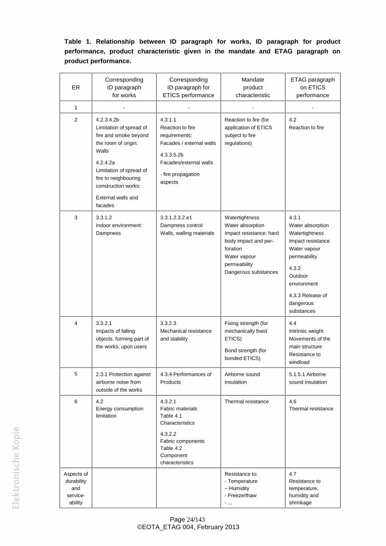
Table 1. Relationship between ID paragraph for works, ID paragraph for product performance, product characteristic given in the mandate and ETAG paragraph on product performance.
ER Corresponding ID paragraph
for works
Corresponding ID paragraph for
ETICS performance
Mandate product
characteristic
ETAG paragraph on ETICS
performance
1 - - - -
2 4.2.3.4.2b Limitation of spread of fire and smoke beyond the room of origin: Walls
4.2.4.2a Limitation of spread of fire to neighbouring construction works:
External walls and facades
4.3.1.1 Reaction to fire requirements: Facades / external walls
4.3.3.5.2b Facades/external walls
- fire propagation aspects
Reaction to fire (for application of ETICS subject to fire regulations)
4.2 Reaction to fire
3 3.3.1.2 Indoor environment: Dampness
3.3.1.2.3.2.e1 Dampness control: Walls, walling materials
Watertightness Water absorption Impact resistance: hard body impact and per-foration Water vapour permeability Dangerous substances
4.3.1 Water absorption Watertightness Impact resistance Water vapour permeability
4.3.2 Outdoor environment
4.3.3 Release of dangerous substances
4 3.3.2.1 Impacts of falling objects, forming part of the works, upon users
3.3.2.3 Mechanical resistance and stability
Fixing strength (for mechanically fixed ETICS)
Bond strength (for bonded ETICS)
4.4 Intrinsic weight Movements of the main structure Resistance to windload
5 2.3.1 Protection against airborne noise from outside of the works
4.3.4 Performances of Products
Airborne sound insulation
5.1.5.1 Airborne sound insulation
6 4.2 Energy consumption limitation
4.3.2.1 Fabric materials Table 4.1 Characteristics
4.3.2.2 Fabric components Table 4.2 Component characteristics
Thermal resistance 4.6 Thermal resistance
Aspects of Resistance to: 4.7 durability - Temperature Resistance to
and – Humidity temperature, service- - Freeze/thaw humidity and ability - ... shrinkage
Page 24/143 ©EOTA_ETAG 004, February 2013
Resistance to freeze/thaw
Dimensional stability
4.1 ER1: MECHANICAL RESISTANCE AND STABILITY
Requirements with respect to the mechanical resistance and stability of non load bearing parts of the works are not included in this Essential Requirement but are treated under the Essential Requirement Safety in use (see Clause 4.4).
4.2 ER2: SAFETY IN CASE OF FIRE
The Essential Requirement laid down in the Council Directive 89/106/EEC is as follows: The
construction works shall be designed and built in such a way that in the event of an outbreak of fire: - the generation and spread of fire and smoke within the works are limited, - the spread of fire to neighbouring construction works is limited, - occupants can leave the works or be secured by other means, - the safety of rescue teams is taken into consideration.
The following aspects of performance are relevant to this Essential Requirement for ETICS:
Reaction to fire:
The reaction to fire performance of ETICS shall be in accordance with laws, regulations and administrative provisions applicable to the ETICS in its intended end use application. This performance shall be expressed in the form of a classification specified in accordance with the relevant EC decision and the relevant CEN classification standard.
4.3 ER3: HYGIENE, HEALTH AND ENVIRONMENT
4.3.1 Indoor environment, dampness
As far as dampness is concerned for external walls, two requirements have to be considered, for which ETICS have a favourable effect:
- moisture proofing from outside damp Walls shall prevent moisture from the ground from entering the building and shall not carry moisture from the ground to any part where it could cause damage. External walls shall also resist the penetration of rain and snow to the inside of the building; they shall not be damaged by rain and snow and shall not carry moisture to any part where it could cause damage.
- avoiding condensation on internal surfaces and interstitial condensation. Surface condensation is usually reduced by the application of ETICS.
Under normal conditions of use, harmful interstitial condensation does not occur in the ETICS. Where there is a high incidence of water vapour internally, appropriate precautions shall be taken to prevent the ETICS from becoming damp, for example by suitable design of the products and choice of materials.
To ensure that the first of the above mentioned characteristics is sufficiently retained, the performance on exposure to mechanical stresses under normal use shall be considered, i.e.:
Page 25/143 ©EOTA_ETAG 004, February 2013
- the ETICS shall be designed so that it retains its properties under the effect of impacts caused by normal traffic and normal use. Its performance shall be such that the effect of normal accidental or deliberately caused unexceptional impact does not cause any damage,
- where applicable, it shall be possible to lean standard maintenance equipment against the ETICS, without causing any breaks or perforation of the render.
This means that for ER3 the following product characteristics have to be assessed for the
ETICS and/or each of its components: - water absorption, - watertightness, - impact resistance, - water vapour permeability, - thermal characteristics (covered under ER6).
4.3.2 Outdoor environment
Installations and construction works shall not release pollutants to the immediate environment (air, soil, water).
The content and rate of release of pollutants to outdoor air, soil and water for building materials used in external walls shall therefore be in accordance with laws, regulations and administrative provisions, applicable for the location where the product is incorporated in the works.
4.3.3 Release of dangerous substances
The kit shall be such that, when installed according to the appropriate provisions of the Member States, it allows for the satisfaction of the Essential Requirement 3 of the CPD as expressed by the national provisions of the Member States. Where applicable, the kit shall also satisfy ER 3 in respect of the product being allowed to be placed on the market (for example meeting content restrictions).
4.4 ER4: SAFETY IN USE
Even though an ETICS is without a structural intended use, mechanical resistance and stability is still required.
The ETICS shall be stable to the combined stresses generated by normal loads such as intrinsic weight, temperature, humidity and shrinkage, as well as movements of the main structure and wind forces (suction).
This means that for ER 4, the following product characteristics have to be assessed for the ETICS and/or its components.
Effect of intrinsic weight: The ETICS shall support itself without harmful deformation.
Performance on exposure to movements of the main structure: Normal movements of the main structure shall not give rise to any crack formation or loss of adhesion in the ETICS. The ETICS shall withstand movements due to the temperature and stress
variations except at structural joints where special precautions have to be taken.
Page 26/143 ©EOTA_ETAG 004, February 2013
Effect of the wind suction: The ETICS shall, with a sufficient safety factor, exhibit appropriate mechanical resistance to the
forces of pressure, suction and vibration, due to wind.
4.5 ER5: PROTECTION AGAINST NOISE
As an ETICS may have a positive or negative effect on the airborne sound insulation of a wall which it is installed onto, the performance of the ETICS shall be known in order to determine the airborne sound insulation of the whole construction envelope.
4.6 ER6: ENERGY ECONOMY AND HEAT RETENTION
ETICS improve thermal insulation and make it possible to reduce heating (in winter) and air conditioning (in summer).
Therefore the improvement of the thermal resistance of the wall introduced by the ETICS shall be assessed so that it can be introduced in the thermal calculations required by the national regulations on energy consumption.
Mechanical fixings or temporary anchor fixings can cause localised differences in temperature. The thermal bridges shall be assessed or assurance shall be obtained that this effect is small enough not to influence the thermal insulating properties.
In order to establish the benefits of the ETICS to the wall, relevant component characteristics
shall be specified as follows: - thermal conductivity/resistance, - water vapour permeability (covered under ER3), - water absorption (covered under ER3).
4.7. ASPECTS OF DURABILITY AND SERVICEABILITY
All of the ER’s mentioned above shall be fulfilled for the life of the ETICS under the actions to which it is subjected.
Comment: It should be noted that the substrate can influence the ETICS durability.
Durability of the ETICS: The ETICS shall be stable to temperature, humidity and shrinkage.
Neither high nor low temperatures shall exercise a destructive or irreversibly deforming effect.
Low air temperatures of the order of - 20°C and high air temperatures of + 50°C are generally regarded as the extremes in temperature change. In northern European countries however, the temperatures of the air can decrease to - 40°C.
Solar radiation increases the surface temperatures of the ETICS when exposed. The increase depends on the radiation flow and the energy absorption of the surface (colour). It is generally considered that the maximum surface temperature is 80°C.
A change (of the order of 30°C) in the surface temperature shall not cause any damage, e.g. a sudden change due to prolonged exposure to solar radiation followed by intensive rain, or the change of temperature between sun and shade.
In addition, steps shall be taken to prevent crack formation both at the expansion joints of the structure and where elements of the facade are of different materials, e.g. connections to windows.
Page 27/143 ©EOTA_ETAG 004, February 2013
Durability of components All components shall retain their properties during the overall service life of the ETICS under normal conditions of use and maintenance such that the ETICS quality is maintained. This requires the following:
- All components shall display chemical-physical stability and be at least reasonably predictable if not absolutely known. Where reactions between materials in contact occur they shall take place slowly,
- All materials shall be either naturally resistant to, or be treated or protected against attack by, corrosion,
- All materials shall be compatible with each other.
Page 28/143 ©EOTA_ETAG 004, February 2013
5 METHODS OF VERIFICATION
5.0 GENERAL
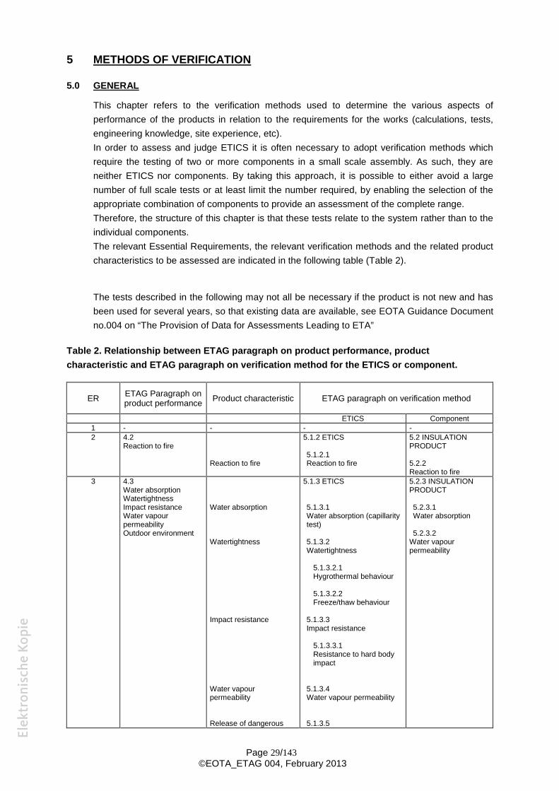
This chapter refers to the verification methods used to determine the various aspects of performance of the products in relation to the requirements for the works (calculations, tests, engineering knowledge, site experience, etc). In order to assess and judge ETICS it is often necessary to adopt verification methods which require the testing of two or more components in a small scale assembly. As such, they are neither ETICS nor components. By taking this approach, it is possible to either avoid a large number of full scale tests or at least limit the number required, by enabling the selection of the appropriate combination of components to provide an assessment of the complete range. Therefore, the structure of this chapter is that these tests relate to the system rather than to the individual components. The relevant Essential Requirements, the relevant verification methods and the related product characteristics to be assessed are indicated in the following table (Table 2).
The tests described in the following may not all be necessary if the product is not new and has been used for several years, so that existing data are available, see EOTA Guidance Document no.004 on “The Provision of Data for Assessments Leading to ETA”
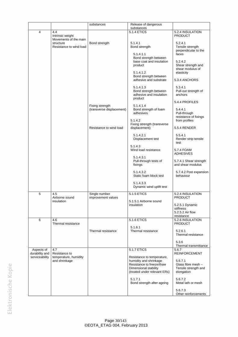
Table 2. Relationship between ETAG paragraph on product performance, product characteristic and ETAG paragraph on verification method for the ETICS or component.
ER ETAG Paragraph on product performance Product characteristic ETAG paragraph on verification method
ETICS Component 1 - - - -2 4.2
Reaction to fire
Reaction to fire
5.1.2 ETICS
5.1.2.1 Reaction to fire
5.2 INSULATION PRODUCT
5.2.2 Reaction to fire
3 4.3 Water absorption Watertightness Impact resistance Water vapour permeability Outdoor environment
Water absorption
Watertightness
Impact resistance
Water vapour permeability
Release of dangerous
5.1.3 ETICS
5.1.3.1 Water absorption (capillarity test)
5.1.3.2 Watertightness
5.1.3.2.1 Hygrothermal behaviour
5.1.3.2.2 Freeze/thaw behaviour
5.1.3.3 Impact resistance
5.1.3.3.1 Resistance to hard body impact
5.1.3.4 Water vapour permeability
5.1.3.5
5.2.3 INSULATION PRODUCT
5.2.3.1 Water absorption
5.2.3.2 Water vapour permeability
Page 29/143 ©EOTA_ETAG 004, February 2013
substances Release of dangerous substances
4 4.4 Intrinsic weight Movements of the main structure Resistance to wind load
Bond strength
Fixing strength (transverse displacement)
Resistance to wind load
5.1.4 ETICS
5.1.4.1 Bond strength
5.1.4.1.1 Bond strength between base coat and insulation product
5.1.4.1.2 Bond strength between adhesive and substrate
5.1.4.1.3 Bond strength between adhesive and insulation product
5.1.4.1.4 Bond strength of foam adhesives
5.1.4.2 Fixing strength (transverse displacement)
5.1.4.2.1 Displacement test
5.1.4.3 Wind load resistance
5.1.4.3.1 Pull-through tests of fixings
5.1.4.3.2 Static foam block test
5.1.4.3.3 Dynamic wind uplift test
5.2.4 INSULATION PRODUCT
5.2.4.1 Tensile strength perpendicular to the faces
5.2.4.2 Shear strength and shear modulus of elasticity
5.3.4 ANCHORS
5.3.4.1 Pull-out strength of anchors
5.4.4 PROFILES
5.4.4.1 Pull-through resistance of fixings from profiles
5.5.4 RENDER
5.5.4.1 Render strip tensile test
5.7.4 FOAM ADHESIVES
5.7.4.1 Shear strength and shear modulus
5.7.4.2 Post expansion behaviour
5 4.5 Airborne sound insulation
Single number improvement values
5.1.5 ETICS
5.1.5.1 Airborne sound insulation
5.2.4 INSULATION PRODUCT
5.2.5.1 Dynamic stiffness 5.2.5.2 Air flow resistance
6 4.6 Thermal resistance
Thermal resistance
5.1.6 ETICS
5.1.6.1 Thermal resistance
5.2.6 INSULATION PRODUCT
5.2.6.1 Thermal resistance
5.3.6 Thermal transmittance
Aspects of 4.7 5.1.7 ETICS 5.6.7 durability and Resistance to REINFORCEMENT serviceability temperature, humidity
and shrinkage Resistance to temperature, humidity and shrinkage Resistance to freeze/thaw Dimensional stability (treated under relevant ERs)
5.1.7.1 Bond strength after ageing
5.6.7.1 Glass fibre mesh – Tensile strength and elongation
5.6.7.2 Metal lath or mesh
5.6.7.3 Other reinforcements
Page 30/143 ©EOTA_ETAG 004, February 2013
5.1 TEST ON THE ETICS
As much as possible (all tests carried out at the same time for example), all the tests shall be performed on the same production lot for each component.
5.1.1 Mechanical resistance and stability
Not relevant
5.1.2 Safety in case of fire
5.1.2.1 Reaction to fire
The ETICS shall be tested, using the test method(s) relevant for the corresponding reaction to fire class, in order to be classified according to EN 13501-1.
If no performance is determined, the products fall in class F without testing.
Method of the test:
The determination of the worst case(s) as well as the mounting and fixing provisions that are considered to be appropriate for the testing and are representative of the intended end use application are specified in Annex D.
Note: A European reference fire scenario has not been laid down for façades. In some Member States, the classification of ETICS according to EN 13501-1 might not be sufficient for the use in façades. An additional assessment of ETICS according to national provisions (e.g. on the basis of a large scale test) might be necessary to comply with Member State regulations, until the existing European classification system has been completed.
Page 31/143 ©EOTA_ETAG 004, February 2013
5.1.3 Hygiene, health and the environment
5.1.3.1 Water absorption (capillarity test)
These tests have 3 purposes, to determine: - the water absorption, in order to assess, in Chapter 6, whether it is acceptable, - which finishing coats should be applied on the rig to be subjected to hygrothermal testing
(5.1.3.2.1), - whether the freeze-thaw testing described in 5.1.3.2.2 is necessary.
Preparation of the samples:
Samples are prepared, each by taking a piece of the specified insulation product, surface area to be at least 200 mm x 200 mm, and applying, in accordance with the ETA-applicant’s instructions, e.g. thickness, mass per unit area and method of application, both:
- the reinforced base coat alone
and
- all the configurations of complete rendering systems proposed by the ETA-applicant, i.e. reinforced base coat covered with each type of finishing coat and (associating or not) key coat and/or decorative coat. If the application of the key coat and/or the decorative coat is optional, at least configurations without them shall be tested.
Exception for not testing all the above mentioned configurations can be accepted provided that a technical argumentation is given in the Evaluation Report.
Within a type of finishing coat, the test shall be carried out with at least the thickest layer (generally higher particle size grading with floated finishing aspect).
Three samples are prepared for each configuration. Quantities and/or thicknesses applied shall be recorded as well as identification of the render’s components according to Annex C.
The prepared samples are conditioned for at least 7 days at (23 ± 2)°C and (50 ± 5) % RH.
The edges of the samples, including the insulation product, are sealed against water, to ensure that during subsequent testing, only the face of the reinforced base coat or the rendering system is subject to water absorption.
They are then subject to a series of 3 cycles comprising the following phases:
- 24 h immersion in a water bath (tap water) at (23 ± 2)°C. The samples are immersed rendered face downwards, to a depth of 2 to 10 mm, the depth of immersion dependent upon surface roughness. To achieve complete wetting of rough surfaces, the samples shall be tilted as they are introduced into the water. The depth of immersion can be regulated in the water tank by means of a height-adjustable slat.
- 24 h drying at (50 ± 5)°C.
If interruptions are necessary, e.g. at week-ends or holidays, the samples are stored at (23 ± 2)°C and (50 ± 5)% RH after the drying at (50 ± 5)°C.
After the cycles, the samples are stored for at least 24 h at (23 ± 2)°C and (50 ± 5)% RH.
Capillarity test procedure:
To start the capillarity test the samples are again immersed in a water bath as described above.
Page 32/143 ©EOTA_ETAG 004, February 2013
t ,
The samples are weighed after 3 minutes immersion in the bath (reference mass) and then after 1 hour and 24 hours. Prior to the second and subsequent weighing, water adhering to the surface of the sample is removed with a damp sponge cloth.
Analysis of results:
Calculation is undertaken to determine the mean water absorption of the three samples per square metre after 1 and 24 hours. The outcome of these results will determine the following:
- Acceptability of the ETICS : see § 6.1.3.1
- Hygrothermal behaviour : For the choice of the finishing coats to be applied on the rig, see Annex B and § 5.1.3.2.1
- Freeze/Thaw test: see Annex B The freeze/thaw test (§ 5.1.3.2.2.) is necessary if the water absorption of either the reinforced base coat or of the rendering coating is equal to or more than 0,5 kg/m² after 24 hours.
Footnote – Special requirements for some ETICS:
- In order to provide information about the stabilisation, the water absorption measured can be plotted on a chart as a function of
- If the ETICS is applied down to the ground and is therefore exposed to rising damp, the Approval Body may need to develop additional tests in an appropriate way subject to consensus within EOTA.
5.1.3.2 Watertightness
5.1.3.2.1 Hygrothermal Behaviour
Based on the outcome of the water absorption test, the specification of the product to be tested is determined, e.g. the number of finishing coats (see Annex B)
Some samples are prepared at the same time as the rig in order to evaluate the following characteristics after heat/rain and heat/cold cycles (for sample size and number: see relevant test method): - Bond strength between the base coat and insulation product (only if the low part of the rig
does not only consist of the reinforced base coat alone, i.e. ETICS with only one finishing coat) (5.1.4.1.1)
- Tensile strength and elongation at break (Annex C, C1.3.2) (for products with an application thickness up to 5 mm).
In the case of reinforced base coat with a thickness greater than 5 mm, complementary samples shall also be prepared to perform the test on the hardened product according to Annex C (C1.3.1)
Principles related to the preparation of the rig:
- As a general rule, only one reinforced base coat and at the very most four finishing coats (vertical divisions) can be applied per rig.
- If several adhesives are proposed for the ETICS, only one shall be tested on the rig.
- If more than 4 finishing coats are proposed for the ETICS, the maximum number of coats, representative of the different types proposed, shall be tested on rig(s). Furthermore, if
Page 33/143 ©EOTA_ETAG 004, February 2013
the water absorption of the reinforced base coat after 24 h is equal to or more than 0,5 kg/m² (see 5.1.3.1), each type of finishing coat containing a pure polymeric binder (non cementitious) shall be submitted to hygrothermal cycles on rig(s) . Any finishing coats not tested on the rig shall be examined according to 5.1.7.1.2.
- If different finishing coats can be used in the ETICS, the lower part of the test piece (1,5 x insulating panel height) consists of the reinforced base coat only without any finishing coat.
- If several ETICS differ only in the method of fixing (bonded or mechanically fixed) of the insulation product, the test is only carried out on the ETICS applied with adhesive at the edge of the rig and with mechanical fixings devices in the centre.
- If several ETICS differ only in the type of insulation product, two insulation products can be applied to the rig. The insulation products are divided vertically at the centre of each rig.
- The ETICS is applied, in accordance with the manufacturer’s instructions, to a sufficiently stabilised masonry or concrete substrate.
- The ETICS shall also be applied to the lateral faces with a uniform maximum thickness of insulation product of 20 mm. If the insulation product is not available in this thickness (Mineral wool Lamella for example), the lateral faces can be covered with a thickness of 20 mm expanded polystyrene.
- Insulation product requiring stabilisation (prescribed delay between production and sale) shall be no older than 15 days beyond the minimum specified period.
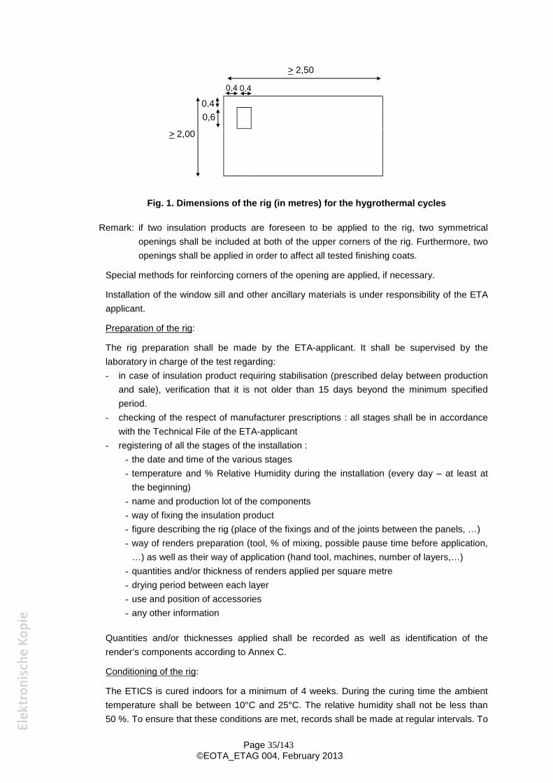
- The dimensions of the rig shall be: - - surface 6 m² - - width 2,50 m - - height 2,00 m
A rectangular opening (consisting of the absence of the ETICS on the substrate at this area) is included at the corner of the rig, 0,40 m wide by 0,60 m high, positioned 0,40 m from the edges.
Page 34/143 ©EOTA_ETAG 004, February 2013
> 2,50
0,4 0,4
0,4 0,6
> 2,00
Fig. 1. Dimensions of the rig (in metres) for the hygrothermal cycles
Remark: if two insulation products are foreseen to be applied to the rig, two symmetrical openings shall be included at both of the upper corners of the rig. Furthermore, two openings shall be applied in order to affect all tested finishing coats.
Special methods for reinforcing corners of the opening are applied, if necessary.
Installation of the window sill and other ancillary materials is under responsibility of the ETA applicant.
Preparation of the rig:
The rig preparation shall be made by the ETA-applicant. It shall be supervised by the laboratory in charge of the test regarding: - in case of insulation product requiring stabilisation (prescribed delay between production
and sale), verification that it is not older than 15 days beyond the minimum specified period.
- checking of the respect of manufacturer prescriptions : all stages shall be in accordance with the Technical File of the ETA-applicant
- registering of all the stages of the installation : - the date and time of the various stages - temperature and % Relative Humidity during the installation (every day – at least at
the beginning) - name and production lot of the components - way of fixing the insulation product - figure describing the rig (place of the fixings and of the joints between the panels, …) - way of renders preparation (tool, % of mixing, possible pause time before application,
…) as well as their way of application (hand tool, machines, number of layers,…) - quantities and/or thickness of renders applied per square metre - drying period between each layer - use and position of accessories - any other information
Quantities and/or thicknesses applied shall be recorded as well as identification of the render’s components according to Annex C.
Conditioning of the rig:
The ETICS is cured indoors for a minimum of 4 weeks. During the curing time the ambient temperature shall be between 10°C and 25°C. The relative humidity shall not be less than 50 %. To ensure that these conditions are met, records shall be made at regular intervals. To
Page 35/143 ©EOTA_ETAG 004, February 2013
prevent the ETICS from drying out too rapidly, the ETA applicant may require the render to be wetted once per week by spraying for approximately 5 minutes. This wetting shall start at a time according to the prescriptions of the ETA-applicant.
During the curing time any deformations of the ETICS, i.e. blistering, cracking, are recorded.
For a reinforced base coat with a thickness up to 5 mm, some samples are prepared according to Annex C § C.1.3.2 and placed in the opening of the rig.
Hygrothermal cycles
The test apparatus is positioned against the front face of the rig, 0,10 to 0,30 m from the edges.
The specified temperatures during the cycles are measured at the surface of the rig. The regulation shall be obtained by adjustment of the air temperature.
Heat - rain cycles: The rig is subjected to a series of 80 cycles, comprising the following phases: 1- heating to 70°C (rise for 1 hour) and maintaining at (70 ± 5)°C and 10 to 30% RH for
2 hours (total of 3 hours), 2- spraying for 1 hour (water temperature (+ 15 5)°C, amount of water 1 l/m² min), 3- leave for 2 hours (drainage).
Heat-cold cycles:
After at least 48 hours of subsequent conditioning at temperatures between 10 and 25°C and a minimum relative humidity of 50 %, the same test rig is exposed to 5 heat/cold cycles of 24 hours comprising the following phases: 1- exposure to (50 ± 5)°C (rise for 1 hour) and maximum 30% RH for 7 hours (total of
8 hours), 2- exposure to (- 20 ± 5)°C (fall for 2 hours) for 14 hours (total of 16 hours).
Observations during the test:
At periods of every four cycles during the heat/rain cycles and at every cycle during the heat/cold cycles, observations relating to a change in characteristics or performance (blistering, detachment, crazing, loss of adhesion, formation of cracks, etc ...) of the entire ETICS and of the part of the rig consisting of only the reinforced base coat are recorded as follows: - the surface finish of the ETICS is examined to establish whether any cracking has
occurred. The dimensions and position of any cracks shall be measured and recorded, - the surface shall also be checked for any blistering or peeling and the location and extent
shall again be recorded, - the sills and profiles shall be checked for any damage/degradation together with any
associated cracking of the finish. Again, the location and extent shall be recorded.
Following the completion of the test, a further investigation is conducted involving removal of sections containing cracks to observe any water penetration within the ETICS.
After the heat-rain and heat-cold cycles
Bond strength tests according to § 5.1.4.1.1 and § 5.1.7.1.1. and impact resistance test according to § 5.1.3.3 shall be performed, after at least 7 days drying.
Page 36/143 ©EOTA_ETAG 004, February 2013
5.1.3.2.2 Freeze-thaw behaviour
The freeze-thaw test shall be carried out as determined by the analysis of the capillarity test (§ 5.1.3.1), i.e. shall be conducted except if the water absorption after 24 hours of both the reinforced base coat and the rendering system determined with each type of finishing coat is less than 0,5 kg/m².
The test shall be carried out on three samples 500 mm x 500 mm consisting of a piece of the specified insulation product covered by:
- reinforced base coat without finishing coat if its water absorption is equal to or higher than 0,5 kg/m2 after 24 hours,
- all the configurations of rendering systems proposed by the ETA-applicant (i.e. reinforced base coat covered with each type of finishing coat and (associating or not) key coat and/or decorative coat which lead to a water absorption equal to or higher than 0,5 kg/m² after 24 hours. If the application of the key coat and/or the decorative coat is optional, at least configurations without them shall be tested).
These samples are prepared according to the ETA applicant’s instructions and then stored for at least 28 days at (23 ± 2)°C and (50 ± 5) % RH.
Quantities and/or thicknesses applied shall be recorded as well as identification of the render’s components according to Annex C.
Cycles
The samples are then subjected to a series of 30 cycles (one cycle lasts for 24 hours) comprising:
- Exposure to water for 8 hours at initial temperature of (23 ± 2)°C by immersion of the samples, render face downwards, in a water bath, by the method described in 5.1.3.1 Capillarity test,
- Freezing to (- 20 ± 2)°C (fall for 5 hours at the sample surface and for 2 hours in the conditioned air) for respectively 11 and 14 hours (total of 16 hours).
If the test is interrupted, because the samples are handled manually and there are stops during weekends or holidays, the samples shall always be maintained immersed in water between the cycles.
Remark: The specified temperatures are measured at the surface of the samples. The regulation is obtained by conditioned air.
Observations:
At the end of the test, observations relating to a change in characteristics of the surface or to the behaviour of the entire ETICS are recorded according to 5.1.3.2.1.
Any distortion at the edges of the samples shall also be reported.
After the test
A bond strength test shall be performed in accordance with § 5.1.4.1.1 on each sample submitted to freeze-thaw cycles.
Page 37/143 ©EOTA_ETAG 004, February 2013
5.1.3.3 Impact resistance
The hard body impact test shall be performed on the rig after the heat-rain and the heat-cold cycles.
The hard body impact tests shall be performed as described in ISO 7892. The points of impact are selected taking into account various modes of behaviour of walls and their cladding, varying according to whether the impact point is or is not located in an area of greater rigidity (reinforcement).
Hard body impacts (10 Joules) are carried out on 3 samples with the steel ball weighing 1,0 kg and from a height of 1,02 m
Hard body impacts (3 Joules) are carried out on 3 samples with the steel ball weighing 0,5 kg and from a height of 0,61 m.
Observations: - the diameter of the impact is measured and indicated, - the presence of any micro cracks or cracks, at the impact point and at the
circumference, is noted.
For finishing coats not tested on the rig or for complementary tests (double meshes, etc), these tests can also be carried out on samples aged by immersion in water for 6 to 8 days and then dried for at least 7 days at (23 ± 2)°C and (50 ± 5)% RH. Within a type of finishing coat, the test shall be carried out with at least the thinnest layer (generally the lowest particle size grading with ribbed finishing aspect). Quantities and/or thicknesses applied shall be recorded as well as identification of the render’s components according to Annex C.
In case of test with reinforced mesh, the extrapolation of results to very different products (other mesh size, other mass per unit area, etc) shall be carefully examined.
In case of possible optional use of key coat and/or decorative coat, at least the configurations without them shall be tested.
5.1.3.4 Water vapour permeability (resistance to water vapour diffusion)
The test shall be performed on all the configurations of rendering systems proposed by the ETA-applicant, i.e. reinforced base coat covered with each type of finishing coat and (associating or not) key coat and/or decorative coat. If the application of the key coat and/or the decorative coat is optional, configurations with and without shall be tested.
Within a type, the test shall be carried out with the thickest continuous layer (generally higher particles size grading with floated finishing aspect).
Exception for not testing all the above mentioned configurations can be accepted provided that a technical argumentation is given in the Evaluation Report.
The samples are prepared by applying the rendering to the insulation product in accordance with the ETA applicant’s instructions and conditioned for at least 28 days at (23 ± 2)°C and (50 ± 5)% RH. Quantities and/or thicknesses applied shall be recorded as well as identification of the render’s components according to Annex C.
Page 38/143 ©EOTA_ETAG 004, February 2013
Five test samples of at least 5000 mm² are then obtained by separating the rendering system from the insulation product.
The test is carried out on the rendering system in accordance with EN ISO 7783.
The test shall be carried out in an enclosure at (23 ± 2)°C and (50 ± 5)% RH. The dish contains a saturated solution of ammonium dihydrogen phosphate (NH4H2PO4).
The results are expressed in metres (of air) and the resistance to water vapour diffusion is determined as the mean value and rounded to 1/10 m (one decimal).
5.1.3.5 Release of dangerous substances
The applicant shall either:
- submit the chemical constitution and composition of the materials and components of the kit to the Approval Body which will observe strict rules of confidentiality
or
- submit a written declaration to the Approval Body stating whether or not and in which concentration the materials and components of the kit contain substances which have to be classified as dangerous according to Directive 67/548/EEC and Regulation (EC) No 1272/2008 and listed in the "Indicative list on dangerous substances" of the EGDS - taking into account the installation conditions of the construction product and the release scenarios resulting from there.
The use of recycled materials shall always be indicated, because this could lead to the implementation of further assessment and verification methods.
The information concerning the presence of dangerous substances listed in Council Directive 67/548/EEC and Regulation (EC) No 1272/2008 regulated at European level and/or listed in the "Indicative list on dangerous substances" of the EGDS and/or of other dangerous substances, shall be circulated as part of the evaluation report by the issuing Approval Body to the other Approval Bodies, under strict conditions of confidentiality.
5.1.3.5.1 Method of verification
Materials and components of the kit listed in the EOTA TR 034 "General Checklist for ETAGs/CUAPs/ETAs - Content and/or release of dangerous substances in products/kits ", which have to be considered will be verified by the given methods, taking into account the installation conditions of the assembled system/component of the assembled system and the release scenarios resulting from there. Regulations related to placing the product on the market may also need to be taken into account.
Regarding the release scenarios referred to in the EOTA TR 034, the following use categories have to be considered:
Category S/W1: Product with direct contact to soil-, ground- and surface water
Category S/W2: and surface water
Product with no direct contact to but possible impact on soil-, ground-
Category S/W3: water
Product with no contact to and no impact on soil-, ground- and surface
Page 39/143 ©EOTA_ETAG 004, February 2013
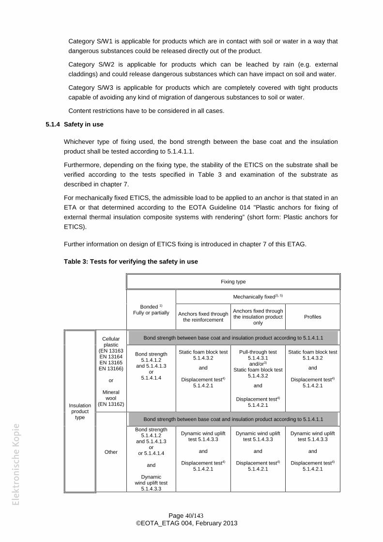
Category S/W1 is applicable for products which are in contact with soil or water in a way that dangerous substances could be released directly out of the product.
Category S/W2 is applicable for products which can be leached by rain (e.g. external claddings) and could release dangerous substances which can have impact on soil and water.
Category S/W3 is applicable for products which are completely covered with tight products capable of avoiding any kind of migration of dangerous substances to soil or water.
Content restrictions have to be considered in all cases.
5.1.4 Safety in use
Whichever type of fixing used, the bond strength between the base coat and the insulation product shall be tested according to 5.1.4.1.1.
Furthermore, depending on the fixing type, the stability of the ETICS on the substrate shall be verified according to the tests specified in Table 3 and examination of the substrate as described in chapter 7.
For mechanically fixed ETICS, the admissible load to be applied to an anchor is that stated in an ETA or that determined according to the EOTA Guideline 014 "Plastic anchors for fixing of external thermal insulation composite systems with rendering” (short form: Plastic anchors for ETICS).
Further information on design of ETICS fixing is introduced in chapter 7 of this ETAG.
Table 3: Tests for verifying the safety in use
Fixing type
Bonded 1)
Fully or partially
Mechanically fixed2), 5)
Anchors fixed through the reinforcement
Anchors fixed through the insulation product
only Profiles
Insulation product
type
Cellular plastic
(EN 13163 EN 13164 EN 13165 EN 13166)
or
Mineral wool
(EN 13162)
Bond strength between base coat and insulation product according to 5.1.4.1.1
Bond strength 5.1.4.1.2
and 5.1.4.1.3 or
5.1.4.1.4
Static foam block test 5.1.4.3.2
and
Displacement test4)
5.1.4.2.1
Pull-through test 5.1.4.3.1 and/or3)
Static foam block test 5.1.4.3.2
and
Displacement test4)
5.1.4.2.1
Static foam block test 5.1.4.3.2
and
Displacement test4)
5.1.4.2.1
Bond strength between base coat and insulation product according to 5.1.4.1.1
Bond strength 5.1.4.1.2
and 5.1.4.1.3 Dynamic wind uplift
test 5.1.4.3.3 Dynamic wind uplift
test 5.1.4.3.3 Dynamic wind uplift
test 5.1.4.3.3
Other or
or 5.1.4.1.4 and and and
and Displacement test4)
5.1.4.2.1 Displacement test4)
5.1.4.2.1 Displacement test4)
5.1.4.2.1 Dynamic
wind uplift test 5.1.4.3.3
Page 40/143 ©EOTA_ETAG 004, February 2013
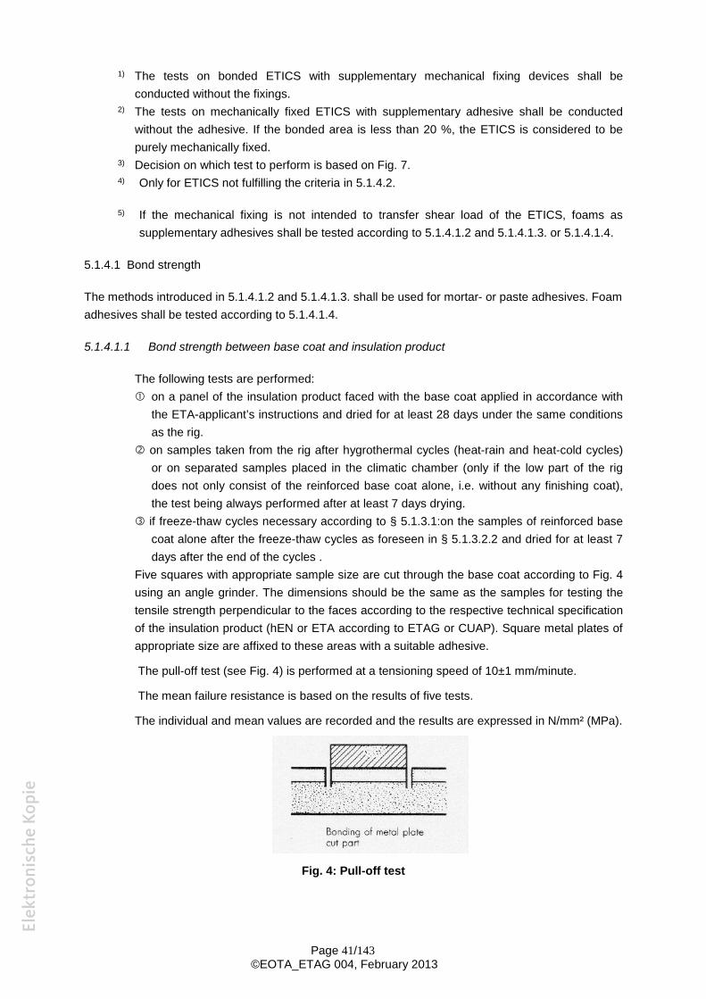
1) The tests on bonded ETICS with supplementary mechanical fixing devices shall be conducted without the fixings.
2) The tests on mechanically fixed ETICS with supplementary adhesive shall be conducted without the adhesive. If the bonded area is less than 20 %, the ETICS is considered to be purely mechanically fixed.
3) Decision on which test to perform is based on Fig. 7. 4) Only for ETICS not fulfilling the criteria in 5.1.4.2.
5) If the mechanical fixing is not intended to transfer shear load of the ETICS, foams as supplementary adhesives shall be tested according to 5.1.4.1.2 and 5.1.4.1.3. or 5.1.4.1.4.
5.1.4.1 Bond strength
The methods introduced in 5.1.4.1.2 and 5.1.4.1.3. shall be used for mortar- or paste adhesives. Foam adhesives shall be tested according to 5.1.4.1.4.
5.1.4.1.1 Bond strength between base coat and insulation product
The following tests are performed: on a panel of the insulation product faced with the base coat applied in accordance with
the ETA-applicant’s instructions and dried for at least 28 days under the same conditions as the rig.
on samples taken from the rig after hygrothermal cycles (heat-rain and heat-cold cycles) or on separated samples placed in the climatic chamber (only if the low part of the rig does not only consist of the reinforced base coat alone, i.e. without any finishing coat), the test being always performed after at least 7 days drying.
if freeze-thaw cycles necessary according to § 5.1.3.1:on the samples of reinforced base coat alone after the freeze-thaw cycles as foreseen in § 5.1.3.2.2 and dried for at least 7 days after the end of the cycles .
Five squares with appropriate sample size are cut through the base coat according to Fig. 4 using an angle grinder. The dimensions should be the same as the samples for testing the tensile strength perpendicular to the faces according to the respective technical specification of the insulation product (hEN or ETA according to ETAG or CUAP). Square metal plates of appropriate size are affixed to these areas with a suitable adhesive.
The pull-off test (see Fig. 4) is performed at a tensioning speed of 10±1 mm/minute.
The mean failure resistance is based on the results of five tests.
The individual and mean values are recorded and the results are expressed in N/mm² (MPa).
Fig. 4: Pull-off test
Page 41/143 ©EOTA_ETAG 004, February 2013
5.1.4.1.2 Bond strength test between adhesive (mortar or paste) and substrate
The test shall be carried out for bonded ETICS only.
The tests are performed on the following substrates: - A substrate consisting of a smooth concrete slab at least 40 mm thick.
The water/cement ratio shall be of the order of 0,45 to 0,48. The tensile strength of the slab shall be at least 1,5 N/mm². The moisture content of the slab prior to the test shall be a maximum of 3 % of the total mass.
Additionally: - For cement-free adhesive the most absorbent substrate of those specified by the
ETA-applicant. The adhesive is spread on the substrate. Normally, the thickness is from 3 to 5 mm, unless another value is agreed between the manufacturer and Approval Body. After allowing the adhesive to cure at (23 ± 2)°C and (50 ± 5) % RH for at least 28 days, 15 squares 15 to 25 cm² in area are cut through the adhesive according to Fig. 4. Metal plates of appropriate size are bonded to the squares using a suitable adhesive. The pull-off test (see Fig. 4) is performed at a tensioning speed of 10±1 mm/minute on the following samples (5 samples each): - without supplementary conditioning (dry condition), - after immersion of the adhesive in water for 2 days and 2 h drying at (23 ± 2)°C and (50 ±
5)% RH, - after immersion of the adhesive in water for 2 days and at least 7 days drying at (23 ± 2)°C
and (50 ± 5)% RH.
The mean failure resistance is based on the results of five tests.
The individual and mean values are recorded and the results expressed in N/mm² (MPa).
The tested thickness of adhesive has to be introduced in Evaluation Report.
5.1.4.1.3 Bond strength test between adhesive (mortar or paste) and insulation product
The test shall be carried out for bonded ETICS only.
The test is performed on the insulation product specified for the ETICS.
The adhesive is spread on the insulation product. Normally, the thickness is from 3 to 5 mm, unless another value is agreed between the manufacturer and Approval Body. After allowing
the adhesive to cure at (23 ± 2)°C and (50 ± 5) % RH for at least 28 days, 15 squares, with
appropriate sample size are cut through the adhesive according to Fig. 4 using an angle
grinder. The dimensions should be the same as the samples for testing the tensile strength
perpendicular to the faces according to the respective technical specification of the insulation
product (hEN or ETA according to ETAG or CUAP). Square metal plates of appropriate size
are affixed to these areas with a suitable adhesive.
The pull-off test (see Fig. 4) is performed with the same conditions as described in 5.1.4.1.2
(5 samples each): - without supplementary conditioning (dry condition), - after immersion of the adhesive in water for 2 days and 2 h drying at (23 ± 2)°C and (50 ±
5)% RH,
Page 42/143 ©EOTA_ETAG 004, February 2013
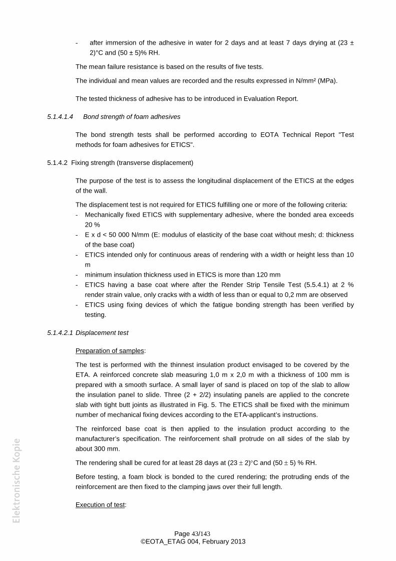
- after immersion of the adhesive in water for 2 days and at least 7 days drying at (23 ± 2)°C and (50 ± 5)% RH.
The mean failure resistance is based on the results of five tests.
The individual and mean values are recorded and the results expressed in N/mm² (MPa).
The tested thickness of adhesive has to be introduced in Evaluation Report.
5.1.4.1.4 Bond strength of foam adhesives
The bond strength tests shall be performed according to EOTA Technical Report "Test methods for foam adhesives for ETICS".
5.1.4.2 Fixing strength (transverse displacement)
The purpose of the test is to assess the longitudinal displacement of the ETICS at the edges of the wall.
The displacement test is not required for ETICS fulfilling one or more of the following criteria: - Mechanically fixed ETICS with supplementary adhesive, where the bonded area exceeds
20 % - E x d < 50 000 N/mm (E: modulus of elasticity of the base coat without mesh; d: thickness
of the base coat) - ETICS intended only for continuous areas of rendering with a width or height less than 10
m - minimum insulation thickness used in ETICS is more than 120 mm - ETICS having a base coat where after the Render Strip Tensile Test (5.5.4.1) at 2 %
render strain value, only cracks with a width of less than or equal to 0,2 mm are observed - ETICS using fixing devices of which the fatigue bonding strength has been verified by
testing.
5.1.4.2.1 Displacement test
Preparation of samples:
The test is performed with the thinnest insulation product envisaged to be covered by the ETA. A reinforced concrete slab measuring 1,0 m x 2,0 m with a thickness of 100 mm is prepared with a smooth surface. A small layer of sand is placed on top of the slab to allow the insulation panel to slide. Three (2 + 2/2) insulating panels are applied to the concrete slab with tight butt joints as illustrated in Fig. 5. The ETICS shall be fixed with the minimum number of mechanical fixing devices according to the ETA-applicant’s instructions.
The reinforced base coat is then applied to the insulation product according to the manufacturer’s specification. The reinforcement shall protrude on all sides of the slab by about 300 mm.
The rendering shall be cured for at least 28 days at (23 2)C and (50 5) % RH.
Before testing, a foam block is bonded to the cured rendering; the protruding ends of the reinforcement are then fixed to the clamping jaws over their full length.
Execution of test:
Page 43/143 ©EOTA_ETAG 004, February 2013
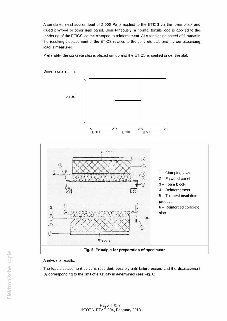
A simulated wind suction load of 2 000 Pa is applied to the ETICS via the foam block and glued plywood or other rigid panel. Simultaneously, a normal tensile load is applied to the rendering of the ETICS via the clamped-in reinforcement. At a tensioning speed of 1 mm/min the resulting displacement of the ETICS relative to the concrete slab and the corresponding load is measured.
Preferably, the concrete slab is placed on top and the ETICS is applied under the slab.
Dimensions in mm:
> 1000
> 500 > 500 > 500
1 – Clamping jaws 2 – Plywood panel 3 – Foam block 4 – Reinforcement 5 – Thinnest insulation product 6 – Reinforced concrete slab
Fig. 5: Principle for preparation of specimens
Analysis of results:
The load/displacement curve is recorded, possibly until failure occurs and the displacement Ue corresponding to the limit of elasticity is determined (see Fig. 6):
Page 44/143 ©EOTA_ETAG 004, February 2013
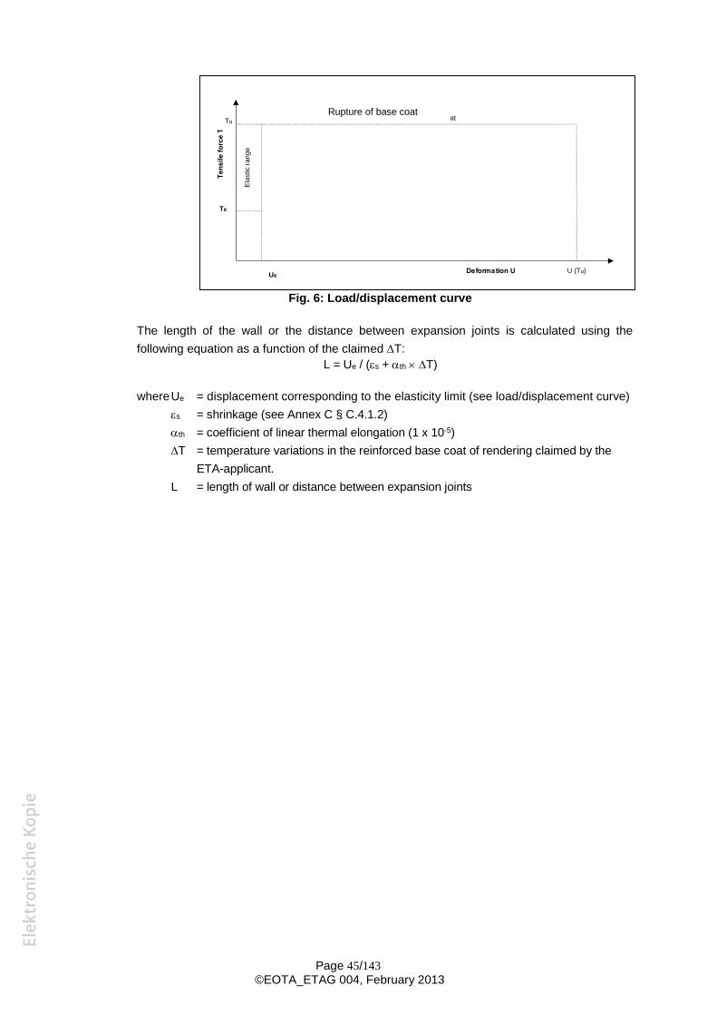
Capture of base co
Deformation U
Tens
ile fo
rce
T
at
Elas
tic ra
nge
Te
Ue U (Tu)
Tu Rupture of base coat
Fig. 6: Load/displacement curve
The length of the wall or the distance between expansion joints is calculated using the following equation as a function of the claimed T:
L = Ue / (s + th T)
whereUe = displacement corresponding to the elasticity limit (see load/displacement curve) s = shrinkage (see Annex C § C.4.1.2) th = coefficient of linear thermal elongation (1 x 10⁻⁵) T = temperature variations in the reinforced base coat of rendering claimed by the
ETA-applicant. L = length of wall or distance between expansion joints
Page 45/143 ©EOTA_ETAG 004, February 2013
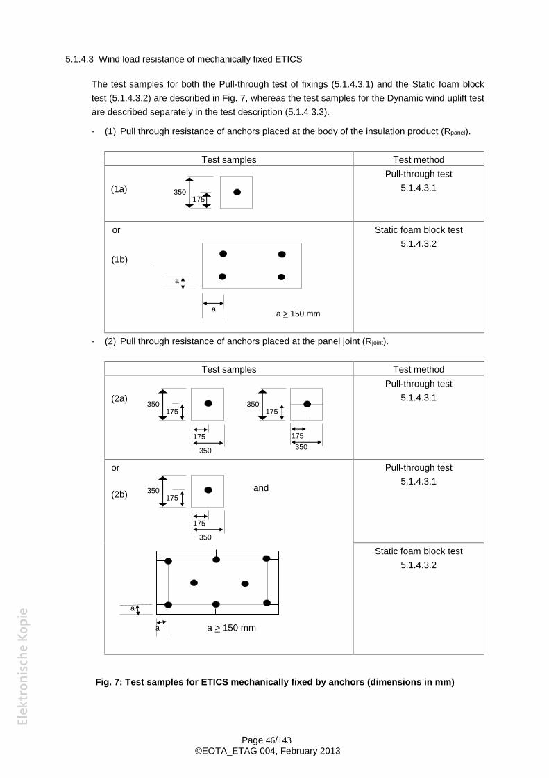
5.1.4.3 Wind load resistance of mechanically fixed ETICS
The test samples for both the Pull-through test of fixings (5.1.4.3.1) and the Static foam block test (5.1.4.3.2) are described in Fig. 7, whereas the test samples for the Dynamic wind uplift test are described separately in the test description (5.1.4.3.3).
- (1) Pull through resistance of anchors placed at the body of the insulation product (Rpanel).
Test samples Test method
350 (1a) 175
Pull-through test 5.1.4.3.1
or
a
(1b)
a a > 150 mm
Static foam block test 5.1.4.3.2
- (2) Pull through resistance of anchors placed at the panel joint (Rjoint).
Test samples Test method
350 175
(2a)
350
175
350 175
175 350
Pull-through test 5.1.4.3.1
or
a
a
350 175 (2b)
a > 150 mm
350
175
and
Pull-through test 5.1.4.3.1
Static foam block test 5.1.4.3.2
Fig. 7: Test samples for ETICS mechanically fixed by anchors (dimensions in mm)
Page 46/143 ©EOTA_ETAG 004, February 2013
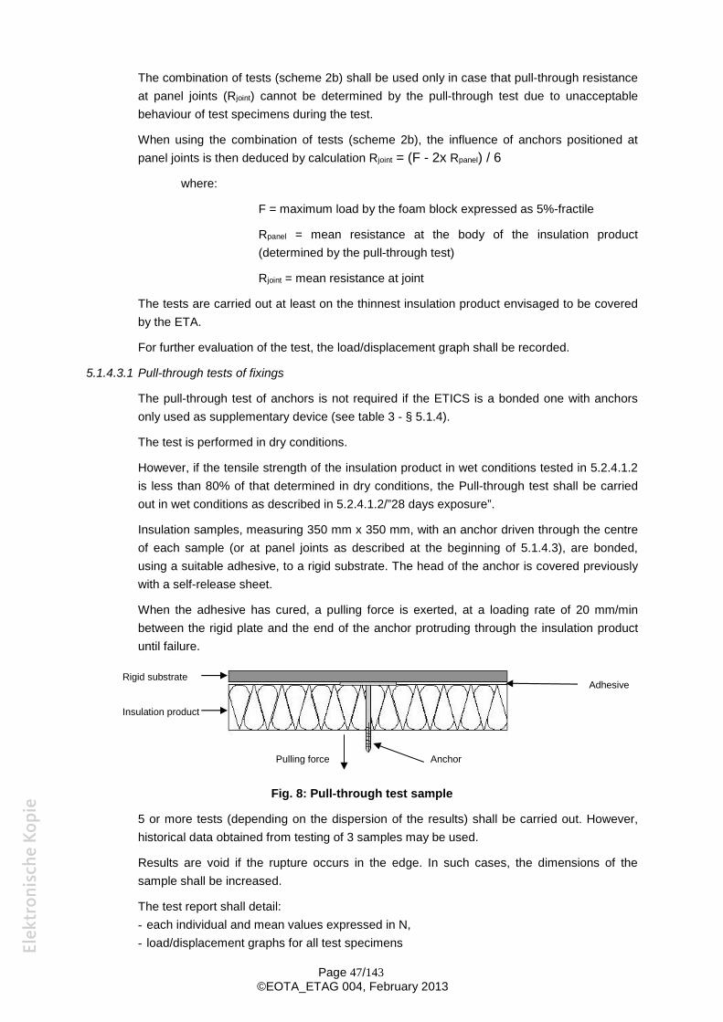
The combination of tests (scheme 2b) shall be used only in case that pull-through resistance at panel joints (Rjoint) cannot be determined by the pull-through test due to unacceptable behaviour of test specimens during the test.
When using the combination of tests (scheme 2b), the influence of anchors positioned at panel joints is then deduced by calculation Rjoint = (F - 2x Rpanel) / 6
where:
F = maximum load by the foam block expressed as 5%-fractile
Rpanel = mean resistance at the body of the insulation product (determined by the pull-through test)
Rjoint = mean resistance at joint
The tests are carried out at least on the thinnest insulation product envisaged to be covered by the ETA.
For further evaluation of the test, the load/displacement graph shall be recorded.
5.1.4.3.1 Pull-through tests of fixings
The pull-through test of anchors is not required if the ETICS is a bonded one with anchors only used as supplementary device (see table 3 - § 5.1.4).
The test is performed in dry conditions.
However, if the tensile strength of the insulation product in wet conditions tested in 5.2.4.1.2 is less than 80% of that determined in dry conditions, the Pull-through test shall be carried out in wet conditions as described in 5.2.4.1.2/”28 days exposure”.
Insulation samples, measuring 350 mm x 350 mm, with an anchor driven through the centre of each sample (or at panel joints as described at the beginning of 5.1.4.3), are bonded, using a suitable adhesive, to a rigid substrate. The head of the anchor is covered previously with a self-release sheet.
When the adhesive has cured, a pulling force is exerted, at a loading rate of 20 mm/min between the rigid plate and the end of the anchor protruding through the insulation product until failure.
Pulling force Anchor
Rigid substrate
Insulation product
Adhesive
Fig. 8: Pull-through test sample
5 or more tests (depending on the dispersion of the results) shall be carried out. However, historical data obtained from testing of 3 samples may be used.
Results are void if the rupture occurs in the edge. In such cases, the dimensions of the
sample shall be increased.
The test report shall detail: - each individual and mean values expressed in N, - load/displacement graphs for all test specimens
Page 47/143 ©EOTA_ETAG 004, February 2013
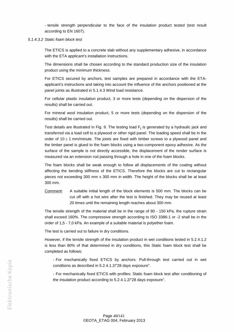
- tensile strength perpendicular to the face of the insulation product tested (test result according to EN 1607).
5.1.4.3.2 Static foam block test
The ETICS is applied to a concrete slab without any supplementary adhesive, in accordance with the ETA applicant’s installation instructions.
The dimensions shall be chosen according to the standard production size of the insulation product using the minimum thickness.
For ETICS secured by anchors, test samples are prepared in accordance with the ETA-applicant’s instructions and taking into account the influence of the anchors positioned at the panel joints as illustrated in 5.1.4.3 Wind load resistance.
For cellular plastic insulation product, 3 or more tests (depending on the dispersion of the results) shall be carried out.
For mineral wool insulation product, 5 or more tests (depending on the dispersion of the results) shall be carried out.
Test details are illustrated in Fig. 9. The testing load Ft is generated by a hydraulic jack and transferred via a load cell to a plywood or other rigid panel. The loading speed shall be in the order of 10 1 mm/minute. The joists are fixed with timber screws to a plywood panel and the timber panel is glued to the foam blocks using a two-component epoxy adhesive. As the surface of the sample is not directly accessible, the displacement of the render surface is measured via an extension rod passing through a hole in one of the foam blocks.
The foam blocks shall be weak enough to follow all displacements of the coating without affecting the bending stiffness of the ETICS. Therefore the blocks are cut to rectangular pieces not exceeding 300 mm x 300 mm in width. The height of the blocks shall be at least 300 mm.
Comment: A suitable initial length of the block elements is 500 mm. The blocks can be cut off with a hot wire after the test is finished. They may be reused at least 20 times until the remaining length reaches about 300 mm.
The tensile strength of the material shall be in the range of 80 - 150 kPa, the rupture strain shall exceed 160%. The compressive strength according to ISO 3386-1 or -2 shall be in the order of 1,5 - 7,0 kPa. An example of a suitable material is polyether foam.
The test is carried out to failure in dry conditions.
However, if the tensile strength of the insulation product in wet conditions tested in 5.2.4.1.2 is less than 80% of that determined in dry conditions, this Static foam block test shall be completed as follows:
- For mechanically fixed ETICS by anchors: Pull-through test carried out in wet conditions as described in 5.2.4.1.2/”28 days exposure”.
- For mechanically fixed ETICS with profiles: Static foam block test after conditioning of the insulation product according to 5.2.4.1.2/”28 days exposure”.
Page 48/143 ©EOTA_ETAG 004, February 2013
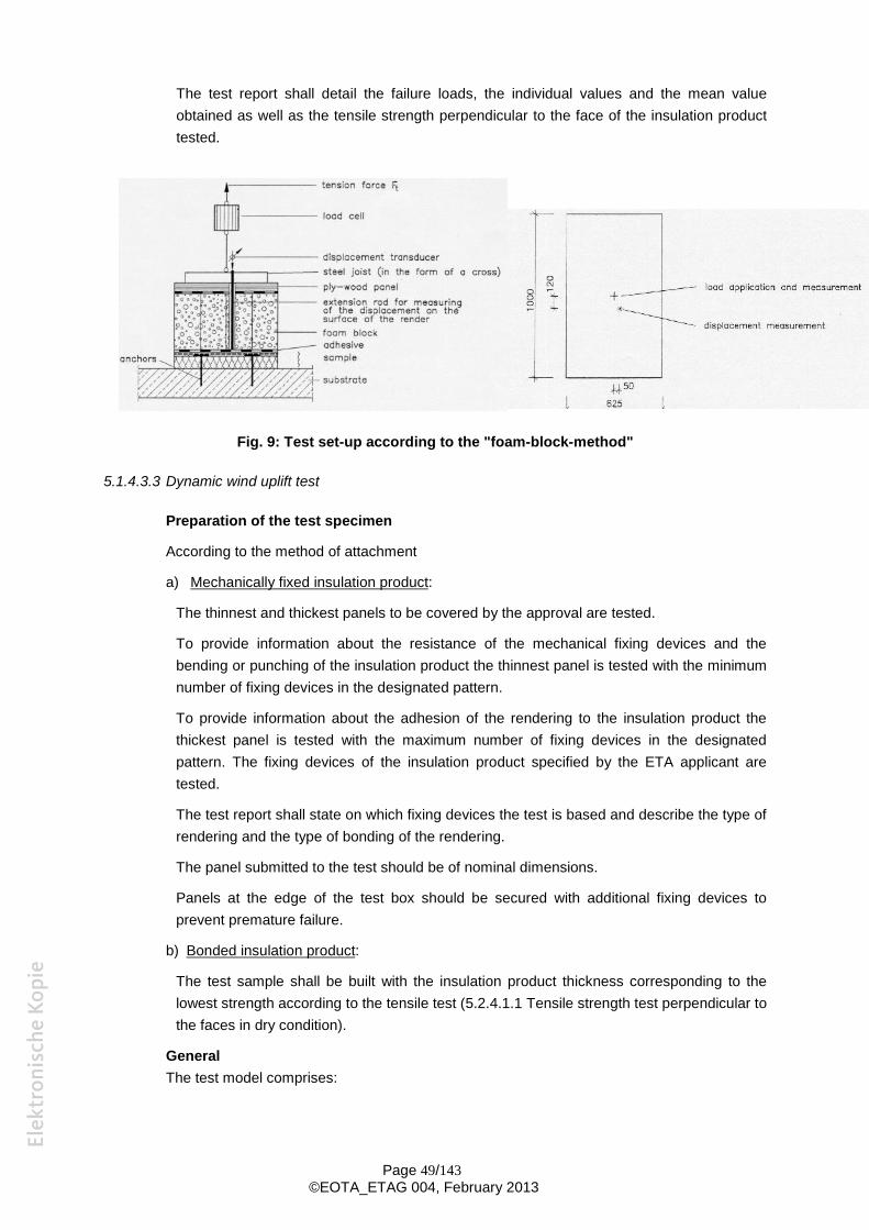
The test report shall detail the failure loads, the individual values and the mean value obtained as well as the tensile strength perpendicular to the face of the insulation product tested.
Fig. 9: Test set-up according to the "foam-block-method"
5.1.4.3.3 Dynamic wind uplift test
Preparation of the test specimen
According to the method of attachment
a) Mechanically fixed insulation product:
The thinnest and thickest panels to be covered by the approval are tested.
To provide information about the resistance of the mechanical fixing devices and the bending or punching of the insulation product the thinnest panel is tested with the minimum number of fixing devices in the designated pattern.
To provide information about the adhesion of the rendering to the insulation product the thickest panel is tested with the maximum number of fixing devices in the designated pattern. The fixing devices of the insulation product specified by the ETA applicant are tested.
The test report shall state on which fixing devices the test is based and describe the type of rendering and the type of bonding of the rendering.
The panel submitted to the test should be of nominal dimensions.
Panels at the edge of the test box should be secured with additional fixing devices to prevent premature failure.
b) Bonded insulation product:
The test sample shall be built with the insulation product thickness corresponding to the lowest strength according to the tensile test (5.2.4.1.1 Tensile strength test perpendicular to the faces in dry condition).
General The test model comprises:
Page 49/143 ©EOTA_ETAG 004, February 2013
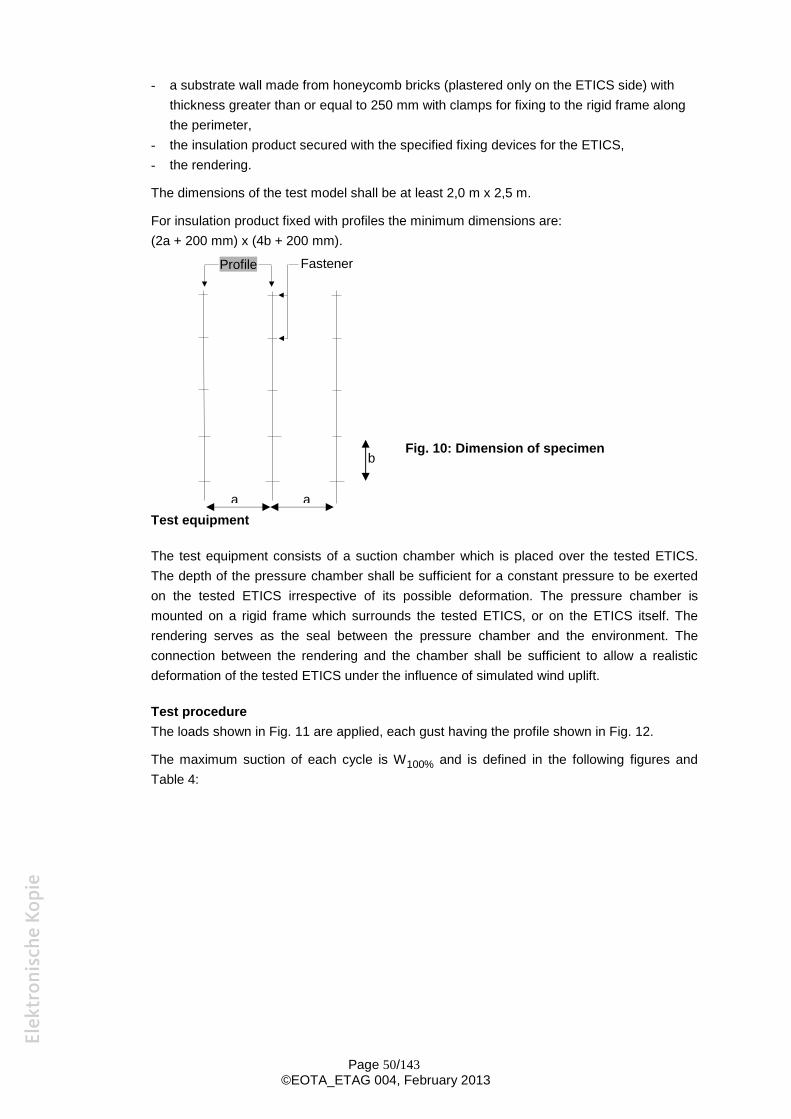
e
- a substrate wall made from honeycomb bricks (plastered only on the ETICS side) with
thickness greater than or equal to 250 mm with clamps for fixing to the rigid frame along the perimeter,
- the insulation product secured with the specified fixing devices for the ETICS, - the rendering.
The dimensions of the test model shall be at least 2,0 m x 2,5 m.
For insulation product fixed with profiles the minimum dimensions are: (2a + 200 mm) x (4b + 200 mm).
Profile Fastener
Fig. 10: Dimension of specimen b
a a Test equipment
The test equipment consists of a suction chamber which is placed over the tested ETICS. The depth of the pressure chamber shall be sufficient for a constant pressure to be exerted on the tested ETICS irrespective of its possible deformation. The pressure chamber is mounted on a rigid frame which surrounds the tested ETICS, or on the ETICS itself. The rendering serves as the seal between the pressure chamber and the environment. The connection between the rendering and the chamber shall be sufficient to allow a realistic deformation of the tested ETICS under the influence of simulated wind uplift.
Test procedure The loads shown in Fig. 11 are applied, each gust having the profile shown in Fig. 12.
The maximum suction of each cycle is W100% and is defined in the following figures and Table 4:
Page 50/143 ©EOTA_ETAG 004, February 2013
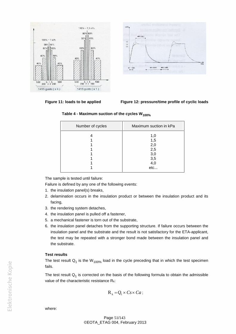
Figure 11: loads to be applied Figure 12: pressure/time profile of cyclic loads
Table 4 - Maximum suction of the cycles W100%
Number of cycles Maximum suction in kPa
4 1 1 1 1 1 1 1
1,0 1,5 2,0 2,5 3,0 3,5 4,0
etc...
The sample is tested until failure: Failure is defined by any one of the following events: 1. the insulation panel(s) breaks, 2. delamination occurs in the insulation product or between the insulation product and its
facing, 3. the rendering system detaches, 4. the insulation panel is pulled off a fastener, 5. a mechanical fastener is torn out of the substrate, 6. the insulation panel detaches from the supporting structure. If failure occurs between the
insulation panel and the substrate and the result is not satisfactory for the ETA-applicant, the test may be repeated with a stronger bond made between the insulation panel and the substrate.
Test results The test result Q1 is the W100% load in the cycle preceding that in which the test specimen fails.
The test result Q1 is corrected on the basis of the following formula to obtain the admissible value of the characteristic resistance Rk:
R k Q1 Cs Ca ;
where:
Page 51/143 ©EOTA_ETAG 004, February 2013
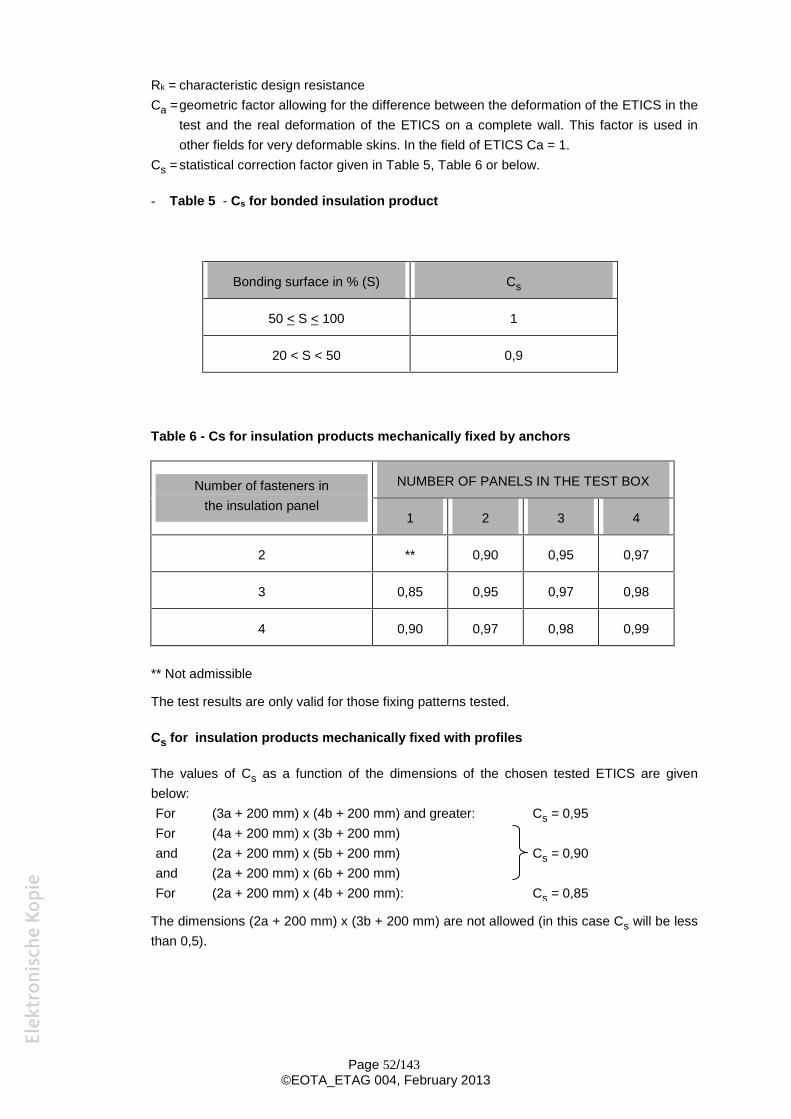
Rk = characteristic design resistance Ca =geometric factor allowing for the difference between the deformation of the ETICS in the
test and the real deformation of the ETICS on a complete wall. This factor is used in other fields for very deformable skins. In the field of ETICS Ca = 1.
Cs = statistical correction factor given in Table 5, Table 6 or below.
- Table 5 - Cs for bonded insulation product
Bonding surface in % (S) Cs
50 < S < 100 1
20 < S < 50 0,9
Table 6 - Cs for insulation products mechanically fixed by anchors
Number of fasteners in NUMBER OF PANELS IN THE TEST BOX
the insulation panel 1 2 3 4
2 ** 0,90 0,95 0,97
3 0,85 0,95 0,97 0,98
4 0,90 0,97 0,98 0,99
** Not admissible
The test results are only valid for those fixing patterns tested.
Cs for insulation products mechanically fixed with profiles
The values of Cs as a function of the dimensions of the chosen tested ETICS are given below: For (3a + 200 mm) x (4b + 200 mm) and greater: Cs = 0,95 For (4a + 200 mm) x (3b + 200 mm) and (2a + 200 mm) x (5b + 200 mm) Cs = 0,90
and (2a + 200 mm) x (6b + 200 mm) For (2a + 200 mm) x (4b + 200 mm): Cs = 0,85
The dimensions (2a + 200 mm) x (3b + 200 mm) are not allowed (in this case Cs will be less than 0,5).
Page 52/143 ©EOTA_ETAG 004, February 2013

5.1.5 Protection against noise
5.1.5.1 Airborne sound insulation
The acoustic performance of an ETICS shall be determined on the basis of laboratory tests carried out in accordance with the standards EN ISO 10140-1, EN ISO 10140-2, EN ISO 10140-4 and EN ISO 10140-5.
For product ranking and prediction, the ETICS shall be tested on a basic wall with low coincidence frequency (heavy basic wall) defined by ISO 10140-1 and ISO 10140-5. Single number improvement values ∆RW,heavy, ∆RW + C)heavy and ∆RW + Ctr)heavy shall be reported as evaluated according to EN ISO 10140-1 Annex G and EN ISO 10140-5. This test covers the acoustic performance of an ETICS when combined with walls of low coincidence frequency with no abnormalities concerning their airborne sound transmission and having a mass per unit area at least ten times larger than that of the ETICS.
An ETICS designed for use with another type of basic wall not corresponding to the standard heavy basic wall (e.g. hollow ceramics or cellular concrete) shall be tested on that type of wall. In such a case, the direct difference of the weighted sound reduction indices of the wall with and without the ETICS, ∆RW,direct, ∆RW + C)direct and ∆RW + Ctr)direct, shall be reported as evaluated according to EN ISO 10140-1 Annex G together with the description of the wall used for testing.
For the configuration of the ETICS to be tested, the following rules shall be taken into account: - insulation products with higher dynamic stiffness provide worse performance - insulation products with lower air flow resistance provide worse performance - a higher number of fixings provides worse performance - a higher adhesive surface coverage provides worse performance - a higher mass of a rendering system provides better performance - a greater thickness of the insulation product provides better performance - the performance for an insulation product thickness between two tested ones can be linearly interpolated - anchors with plastic screws/nails provide better performance than with metal screws/nails
Note: A Technical Report on calculation is being prepared at the time of endorsement of this ETAG. When this document is published, the acoustic performance can also be determined according to the calculation method agreed within EOTA..
5.1.6 Energy economy and heat retention
5.1.6.1 Thermal resistance and thermal transmittance
The additional thermal resistance provided by the ETICS (RETICS) to the substrate wall is calculated from the thermal resistance of the insulation product (Rinsulation), determined in accordance with 5.2.6.1, and from either the tabulated Rrender value of the render system (Rrender is about 0,02 m2K/W) or Rrender determined by test according to EN 12667 or EN 12664 (depending on expected thermal resistance).
RETICS = Rinsulation+ Rrender [(m²K)/W]
as described in EN ISO 6946 and EN ISO 10456.
Page 53/143 ©EOTA_ETAG 004, February 2013
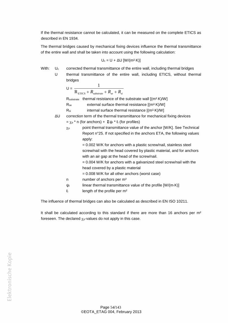
If the thermal resistance cannot be calculated, it can be measured on the complete ETICS as
described in EN 1934.
The thermal bridges caused by mechanical fixing devices influence the thermal transmittance
of the entire wall and shall be taken into account using the following calculation:
Uc = U + ΔU [W/(m²K)]
With: Uc corrected thermal transmittance of the entire wall, including thermal bridges U thermal transmittance of the entire wall, including ETICS, without thermal
bridges 1
U = R R R RETICS substrate se si
Rsubstrate thermal resistance of the substrate wall [(m²K)/W] Rse external surface thermal resistance [(m²K)/W] Rsi internal surface thermal resistance [(m²K)/W]
ΔU correction term of the thermal transmittance for mechanical fixing devices = p * n (for anchors) + Σψi * ℓi (for profiles) p point thermal transmittance value of the anchor [W/K]. See Technical
Report n°25. If not specified in the anchors ETA, the following values apply: = 0.002 W/K for anchors with a plastic screw/nail, stainless steel screw/nail with the head covered by plastic material, and for anchors with an air gap at the head of the screw/nail. = 0.004 W/K for anchors with a galvanized steel screw/nail with the head covered by a plastic material = 0.008 W/K for all other anchors (worst case)
n number of anchors per m² ψi linear thermal transmittance value of the profile [W/(mK)] ℓi length of the profile per m²
The influence of thermal bridges can also be calculated as described in EN ISO 10211.
It shall be calculated according to this standard if there are more than 16 anchors per m² foreseen. The declared p-values do not apply in this case.
Page 54/143 ©EOTA_ETAG 004, February 2013
5.1.7 Aspects of durability and serviceability
5.1.7.1 Bond strength after ageing
This test method is dependent on whether a finishing coat has been tested on the rig or not.
5.1.7.1.1Finishing coat tested on the rig
The bond test is carried out on the rig after the hygrothermal cycles (heat-rain and heat-cold cycles) and at least 7 days drying. Five squares are cut through the rendering system up to the substrate interface according to Fig. 4 using an angle grinder. The dimensions should be the same as the samples for testing the tensile strength perpendicular to the faces according to the respective technical specification of the insulation product (hEN or ETA according to ETAG or CUAP). Metal plates of appropriate size are bonded to it using a suitable adhesive.
Afterwards, the failure resistance (5.1.4.1.1) is measured at a tensioning speed of 1 to 10 mm/minute.
The individual and mean values are recorded and the results expressed in N/mm² (MPa).
5.1.7.1.2Finishing coat not tested on the rig
The test is performed on an insulation panel faced with the rendering system applied in accordance with the manufacturer's instructions.
After allowing the samples to dry at (23 ± 2)°C and (50 ± 5) % RH for at least 28 days, five squares are cut through the rendering system up to the substrate interface according to Fig. 4 using an angle grinder. The dimensions should be the same as the samples for testing the tensile strength perpendicular to the faces according to the respective technical specification of the insulation product (hEN or ETA according to ETAG or CUAP).
The test shall be performed:
- on samples aged by immersion in water for 7 days and then dried for at least 7 days at (23 ± 2)°C and (50 ± 5) % RH.
and/or - if freeze-thaw cycles necessary according to § 5.1.3.1:on the samples after the freeze-
thaw cycles as foreseen in § 5.1.3.2.2 and dried for at least 7 days after the end of the cycles .
In case of possible optional use of key coat and/or decorative coat, at least the configurations without the key coat and/or the decorative coat shall be tested.
Metal plates of appropriate size are bonded to the squares using a suitable adhesive.
Afterwards, the failure resistance (5.1.4.1.1) is measured at a tensioning speed of 10±1 mm/minute.
The individual and mean values are recorded and the results expressed in N/mm² (MPa).
Page 55/143 ©EOTA_ETAG 004, February 2013
TESTS ON COMPONENTS
The tests proposed in 5.2, 5.3, 5.4, 5.5, 5.6 and 5.7 are advisory, based on the assumption that, for some components, the Essential Requirement is satisfied by testing or assessing the kit as a whole. When an ETA-applicant, in consultation with the Approval Body, agree that it is more effective to test and/or control one or more components instead of the kit, one or more characteristics identified as “Not relevant” may be considered to be relevant and added to initial-type and/or identification testing.
Each component used in the ETICS shall be identified in accordance with Annex C.
The component tests indicated in the following by * are also valid as identification tests.
CE marked products which have the necessary performance levels for use in the ETICS do not have to be tested as this section requires.
The ETA applicant shall know of any dangerous substances content of and/or release from the components to assess the whole kit. When sufficient information on the components is not available, testing may be necessary.
5.2. INSULATION PRODUCT
The tests are carried out in accordance with the harmonized technical specification (ETA according to ETAG or CUAP, hEN) for the relevant insulation product.
5.2.1 Mechanical resistance and stability
Not relevant for this component.
5.2.2 Safety in case of fire
According to appropriate harmonized technical specification (ETA according to ETAG or CUAP, hEN) for the relevant insulation product.
5.2.3 Hygiene, health and the environment
5.2.3.1 Water absorption
If no test method is defined in the appropriate harmonized technical specification (ETA according to ETAG or CUAP, hEN) for the relevant insulation product, the test shall be performed in accordance with EN 1609.
5.2.3.2 Water vapour permeability
If no test method is defined in the appropriate harmonized technical specification (ETA according to ETAG or CUAP, hEN) for the relevant insulation product, the test shall be performed in accordance with EN 12086.
5.2.4 Safety in use
5.2.4.1 Tensile test perpendicular to the faces
Page 56/143 ©EOTA_ETAG 004, February 2013
5.2.4.1.1 In dry conditions*
If no test method is defined in the appropriate harmonized technical specification (ETA according to ETAG or CUAP, hEN) for the relevant insulation product, the test shall be performed in accordance with EN 1607.
5.2.4.1.2 In wet conditions*
Where the characteristics of the insulation product could deteriorate by exposure to humidity, the test introduced in 5.2.4.1.1 shall be carried out in wet conditions. The size of the test samples depends on the type of insulation product and should be
identical to the test in dry conditions. The testing is performed as a two test series with a minimum of 8 samples exposed to heat-moisture actions at (70 ± 2)°C and (95 ± 5) % RH in a climatic chamber:
- for 7 days followed by a drying period at (23 ± 2)°C and (50 ± 5) % RH until constant mass is achieved
- for at least 28 days followed by a drying period at (23 ± 2)°C and (50 ± 5) % RH until constant mass is achieved.
The tensile strength perpendicular to the face is determined after each conditioning and expressed in MPa.
Remark: The mass is considered constant when the mass difference between two measurements carried out at intervals of 24 hours is within 5 %.
5.2.4.2 Shear strength and shear modulus of elasticity test*
If no test method is defined in the appropriate harmonized technical specification (ETA according to ETAG or CUAP, hEN) for the relevant insulation product, the test shall be performed in accordance with EN 12090 on a 60 mm thick sample.
5.2.5 Protection against noise
5.2.5.1 Dynamic stiffness
If no test method is defined in the appropriate harmonized technical specification (ETA according to an ETAG or CUAP, hEN) for the relevant insulation product, the test shall be performed in accordance with EN 29052-1 without preloading.
5.2.5.2 Air flow resistance
The air flow resistance shall be determined for porous insulation material (e.g. mineral wool) only. If no test method is defined in the appropriate harmonized technical specification (ETA according to an ETAG or CUAP, hEN) for the relevant insulation product, the test shall be performed in accordance with EN 29053.
Page 57/143 ©EOTA_ETAG 004, February 2013
Page 58/143©EOTA_ETAG 004, February 2013
5.2.6 Energy economy and heat retention
5.2.6.1 Thermal resistance
Thermal resistance of the insulation product is determined as described in the appropriateharmonized technical specification (ETA according to ETAG or CUAP, hEN) for the relevantinsulation product.
5.3. ANCHORS
5.3.1 Mechanical resistance and stability
Not relevant for this component.
5.3.2 Safety in case of fire
Not relevant for this component.
5.3.3 Hygiene, health and the environment
Not relevant for this component.
5.3.4 Safety in use
5.3.4.1 Pull-out strength of anchor
Evaluated according to ETAG 014 "Plastic anchors for fixing of external thermal insulationcomposite systems with rendering" (short form: Plastic anchors for ETICS) or having obtainedan ETA.
5.3.5 Protection against noise
Not relevant for this component.
5.3.6 Energy economy and heat retention
Evaluated according to EOTA TR 025 “Determination of point thermal transmittance of plasticanchors for the anchorage of external thermal insulation composite systems (ETICS).”
5.4. PROFILES AND THEIR FIXINGS
5.4.1 Mechanical resistance and stability
Not relevant for this component.
5.4.2 Safety in case of fire
Not relevant for this component.
5.4.3 Hygiene, health and the environment
Not relevant for this component.
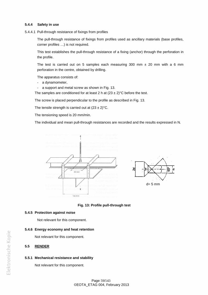
Page 59/143©EOTA_ETAG 004, February 2013
5.4.4 Safety in use
5.4.4.1 Pull-through resistance of fixings from profiles
The pull-through resistance of fixings from profiles used as ancillary materials (base profiles,corner profiles …) is not required.
This test establishes the pull-through resistance of a fixing (anchor) through the perforation inthe profile.
The test is carried out on 5 samples each measuring 300 mm ± 20 mm with a 6 mmperforation in the centre, obtained by drilling.
The apparatus consists of:- a dynamometer,- a support and metal screw as shown in Fig. 13.
The samples are conditioned for at least 2 h at (23 ± 2)°C before the test.
The screw is placed perpendicular to the profile as described in Fig. 13.
The tensile strength is carried out at (23 ± 2)°C.
The tensioning speed is 20 mm/min.
The individual and mean pull-through resistances are recorded and the results expressed in N.
d= 5 mm
Fig. 13: Profile pull-through test
5.4.5 Protection against noise
Not relevant for this component.
5.4.6 Energy economy and heat retention
Not relevant for this component.
5.5 RENDER
5.5.1 Mechanical resistance and stability
Not relevant for this component.
Page 60/143©EOTA_ETAG 004, February 2013
5.5.2 Safety in case of fire
Not relevant for this component.
5.5.3 Hygiene, health and the environment
Not relevant for this component.
5.5.4 Safety in use
5.5.4.1 Render Strip Tensile Test
Purpose:
This test is suitable for the assessment of the crack behaviour of the reinforced base coat bydetermination of the crack width distribution and the "characteristic crack width" Wrk at completedcracking.
Test set-up:
A render strip sample has the size 600 mm x 100 mm x dr and consists of the reinforcementand the base coat (dr = thickness of the base coat with embedded reinforcement). Thereinforcement with a length of 800 mm is arranged within the base coat according to the ETAapplicant’s instructions. It shall protrude about 100 mm at both ends. The protruding parts ofthe reinforcement are placed on the render surfaces on which two metal plates are glued (ifthe reinforcement is not in the middle, two strips shall be glued to a double symmetricalspecimen where the thinner parts of the strips are in the middle of the specimen).
As an alternative to bonding the specimen between two steel plates the fixing of the testsample can be done using a PVC foil (thickness 1.5 to 2 mm, Shore-A-hardness 82) andpneumatic/hydraulic clamping device (see Figure 14).
The test is performed in warp and weft direction on three render strips each. The number ofthreads in one direction shall be the same for all the three strips.
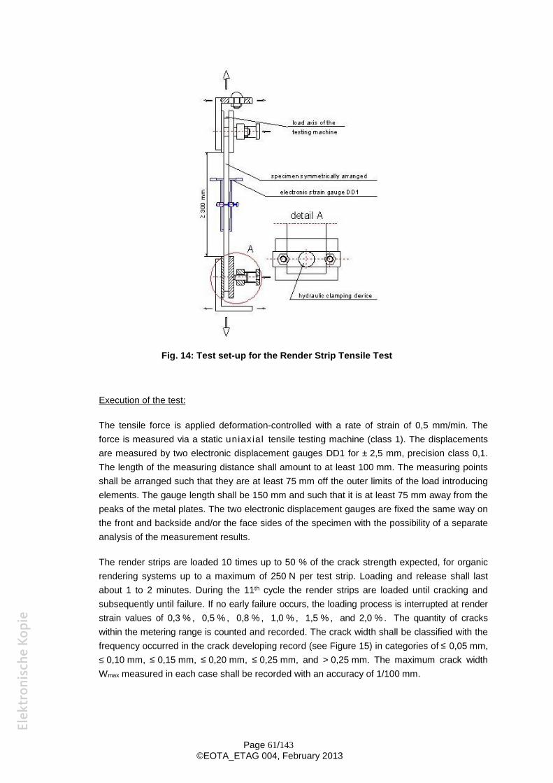
Page 61/143©EOTA_ETAG 004, February 2013
Fig. 14: Test set-up for the Render Strip Tensile Test
Execution of the test:
The tensile force is applied deformation-controlled with a rate of strain of 0,5 mm/min. Theforce is measured via a static uniaxial tensile testing machine (class 1). The displacementsare measured by two electronic displacement gauges DD1 for ± 2,5 mm, precision class 0,1.The length of the measuring distance shall amount to at least 100 mm. The measuring pointsshall be arranged such that they are at least 75 mm off the outer limits of the load introducingelements. The gauge length shall be 150 mm and such that it is at least 75 mm away from thepeaks of the metal plates. The two electronic displacement gauges are fixed the same way onthe front and backside and/or the face sides of the specimen with the possibility of a separateanalysis of the measurement results.
The render strips are loaded 10 times up to 50 % of the crack strength expected, for organicrendering systems up to a maximum of 250 N per test strip. Loading and release shall lastabout 1 to 2 minutes. During the 11th cycle the render strips are loaded until cracking andsubsequently until failure. If no early failure occurs, the loading process is interrupted at renderstrain values of 0,3 % , 0,5 % , 0,8 % , 1,0 % , 1,5 % , and 2,0 % . The quantity of crackswithin the metering range is counted and recorded. The crack width shall be classified with thefrequency occurred in the crack developing record (see Figure 15) in categories of ≤ 0,05 mm,≤ 0,10 mm, ≤ 0,15 mm, ≤ 0,20 mm, ≤ 0,25 mm, and > 0,25 mm. The maximum crack widthWmax measured in each case shall be recorded with an accuracy of 1/100 mm.
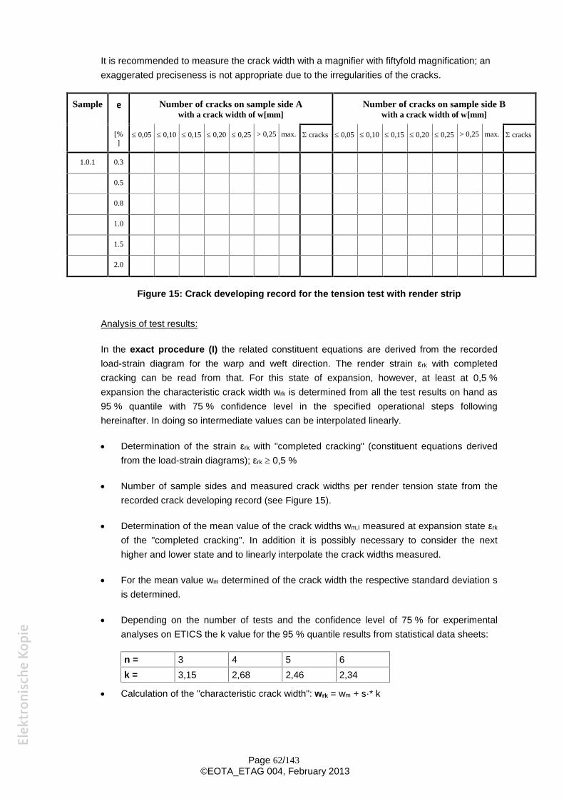
Page 62/143©EOTA_ETAG 004, February 2013
It is recommended to measure the crack width with a magnifier with fiftyfold magnification; anexaggerated preciseness is not appropriate due to the irregularities of the cracks.
Sample Number of cracks on sample side Awith a crack width of w[mm]
Number of cracks on sample side Bwith a crack width of w[mm]
[%] 0,05 0,10 0,15 0,20 0,25 > 0,25 max. cracks 0,05 0,10 0,15 0,20 0,25 > 0,25 max. cracks
1.0.1 0.3
0.5
0.8
1.0
1.5
2.0
Figure 15: Crack developing record for the tension test with render strip
Analysis of test results:
In the exact procedure (I) the related constituent equations are derived from the recordedload-strain diagram for the warp and weft direction. The render strain εrk with completedcracking can be read from that. For this state of expansion, however, at least at 0,5 %expansion the characteristic crack width wrk is determined from all the test results on hand as95 % quantile with 75 % confidence level in the specified operational steps followinghereinafter. In doing so intermediate values can be interpolated linearly.
Determination of the strain εrk with "completed cracking" (constituent equations derivedfrom the load-strain diagrams); εrk 0,5 %
Number of sample sides and measured crack widths per render tension state from therecorded crack developing record (see Figure 15).
Determination of the mean value of the crack widths wm,I measured at expansion state εrk
of the "completed cracking". In addition it is possibly necessary to consider the nexthigher and lower state and to linearly interpolate the crack widths measured.
For the mean value wm determined of the crack width the respective standard deviation sis determined.
Depending on the number of tests and the confidence level of 75 % for experimentalanalyses on ETICS the k value for the 95 % quantile results from statistical data sheets:
n = 3 4 5 6k = 3,15 2,68 2,46 2,34
Calculation of the "characteristic crack width": wrk = wm + s·* k
Page 63/143©EOTA_ETAG 004, February 2013
In the simplified procedure (II) the characteristic crack width for ε'rk = 0,8 % is determined as95 % quantile with 75 % confidence level in the specified operational steps followinghereinafter.
Determination of the mean value of the crack width wm at tension state ε'rk = 0,8 %.
For the mean value wm determined of the crack width the respective standard deviation sis determined.
Depending on the number of tests and the confidence level of 75 % for experimentalanalyses on ETICS the k value for the 95 % quantile results from statistical data sheets:
n = 3 4 5 6k = 3,15 2,68 2,46 2,34
Calculation of the "characteristic crack width": wrk = wm + s·* k
For organic rendering systems without observed crack width the elongation at rupture εru andthe respective ultimate load Nru shall be determined as a mean value from each of theindividual tests.
5.5.5 Protection against noise
Not relevant for this component.
5.5.6 Energy economy and heat retention
Not relevant for this component.
5.6 REINFORCEMENT
5.6.1 Mechanical resistance and stability
Not relevant for this component.
5.6.2 Safety in case of fire
Not relevant for this component
5.6.3 Hygiene, health and the environment
Not relevant for this component.
5.6.4 Safety in use
Not relevant for this component.
5.6.5 Protection against noise
Not relevant for this component.
5.6.6 Energy economy and heat retention
Not relevant for this component.
Page 64/143©EOTA_ETAG 004, February 2013
5.6.7 Aspects of durability and serviceability
5.6.7.1 Glass fibre mesh - Tensile strength and elongation* of the reinforcing fabric
The tensile strength and the elongation of the reinforcement are to be measured in the weftand warp directions on 10 samples respectively. The samples should measure 50 mm by atleast 300 mm. They shall contain at minimum 5 threads within the width.
The clamps of the testing machine shall be covered with a suitable rubber surface and holdthe whole width of the samples. They shall be sufficiently rigid to resist deformation during thetest.
The sample shall be located perpendicular to the clamp of the tensile testing machine.
The free length of the sample between clamps should be 200 mm.
The tensile force is increased with a constant crosshead speed of (100 ± 5) mm/min untilfailure occurs.
Testing is done in the as-delivered state and after immersion in alkaline solution (ageing).
The strength in N at failure and the elongation are recorded.
Samples where the specimen is displaced within the clamps or where the failure occurs at theclamps shall be discarded.
Calculation is undertaken to determine:- the individual values of the tensile strength calculated from the force (F) at failure in
relation to the width (w) of the sample
mm/NinwF
- the individual values of elongation calculated from the change of the length at failure inrelation to the length of the sample between the clamps
%in
- the mean values of tensile strength and elongation calculated from these individualvalues
- the residual value calculated from the mean tensile strength value after ageing in relationto the mean tensile strength value in the as-delivered state.
5.6.7.1.1 Testing in the as-delivered state
The test is conducted after conditioning the samples at (23 ± 2)°C and (50 ± 5) % RH for atleast 24 hours.
5.6.7.1.2 Testing after ageing
The samples are immersed for 28 days in alkaline solution at (23 ± 2)°C (20 samples (10 inthe weft and 10 in the warp direction) in 4 litres solution).
The composition of the solution is as follows:1 g NaOH, 4 g KOH, 0,5 g Ca (OH)2 to one litre of distilled water.
The samples are rinsed by immersion for 5 minutes in acid solution (5 ml HCl (35 % diluted)to 4 litres water) and then placed successively in 3 baths of water (4 litres each). Thesamples are left for 5 minutes in each bath.
Page 65/143©EOTA_ETAG 004, February 2013
They are subsequently dried at (23 ± 2)°C and (50 ± 5) % RH for 48 hours.
5.6.7.2 Metal lath or mesh
For galvanised steel reinforcement, the minimum thickness of the zinc coat required is verifiedusing the relevant EN method.
EN ISO 1460: Metallic coatings - Hot dip galvanized coatings on ferrous materials -Gravimetric determination of the mass per unit area.
EN ISO 1461: Metallic coatings - Hot dip galvanized coatings on fabricated iron and steelarticles - Specifications and test methods.
EN 10244-2: Steel wire and wire products – Non-ferrous metallic coatings on steel wire- Part2: Zinc or zinc alloy coatings.
5.6.7.3 Other reinforcements
Depending on the type of material the Approval Body will perform a suitable test based on5.6.7.1.
5.7. FOAM ADHESIVES
5.7.1 Mechanical resistance and stability
Not relevant for this component.
5.7.2 Safety in case of fire
Not relevant for this component.
5.7.3 Hygiene, health and the environment
Not relevant for this component.
5.7.4 Safety in use
5.7.4.1 Shear strength and shear modulus
The shear strength and shear modulus shall be determined according to EOTA TechnicalReport "Test methods for foam adhesives for ETICS"
5.7.4.2 Post expansion behaviour
The post expansion behaviour shall be determined according to EOTA Technical Report "Testmethods for foam adhesives for ETICS"
5.7.5 Protection against noise
Not relevant for this component.
5.7.6 Energy economy and heat retention
Not relevant for this component.
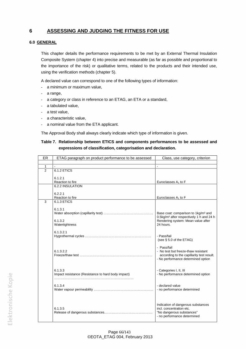
Page 66/143©EOTA_ETAG 004, February 2013
6 ASSESSING AND JUDGING THE FITNESS FOR USE
6.0 GENERAL
This chapter details the performance requirements to be met by an External Thermal InsulationComposite System (chapter 4) into precise and measurable (as far as possible and proportional tothe importance of the risk) or qualitative terms, related to the products and their intended use,using the verification methods (chapter 5).
A declared value can correspond to one of the following types of information:- a minimum or maximum value,- a range,- a category or class in reference to an ETAG, an ETA or a standard,- a tabulated value,- a test value,- a characteristic value,- a nominal value from the ETA applicant.
The Approval Body shall always clearly indicate which type of information is given.
Table 7. Relationship between ETICS and components performances to be assessed andexpressions of classification, categorisation and declaration.
ER ETAG paragraph on product performance to be assessed Class, use category, criterion
1 - -2 6.1.2 ETICS
6.1.2.1Reaction to fire Euroclasses A1 to F6.2.2 INSULATION
6.2.2.1Reaction to fire Euroclasses A1 to F
3 6.1.3 ETICS
6.1.3.1Water absorption (capillarity test) ………………………………………
6.1.3.2Watertightness
6.1.3.2.1Hygrothermal cycles ……………………………………………………
6.1.3.2.2Freeze/thaw test …………………………………………………………
6.1.3.3Impact resistance (Resistance to hard body impact)………………………………………………………………
6.1.3.4Water vapour permeability ………………………………………………
6.1.3.5Release of dangerous substances.…………………………………….
Base coat: comparison to 1kg/m² and0.5kg/m² after respectively 1 h and 24 hRendering system: Mean value after24 hours.
- Pass/fail(see § 5.0 of the ETAG)
- Pass/fail- No test but freeze-thaw resistant
according to the capillarity test result.- No performance determined option
- Categories I, II, III- No performance determined option
- declared value- no performance determined
Indication of dangerous substancesincl. concentration etc.”No dangerous substances”- no performance determined
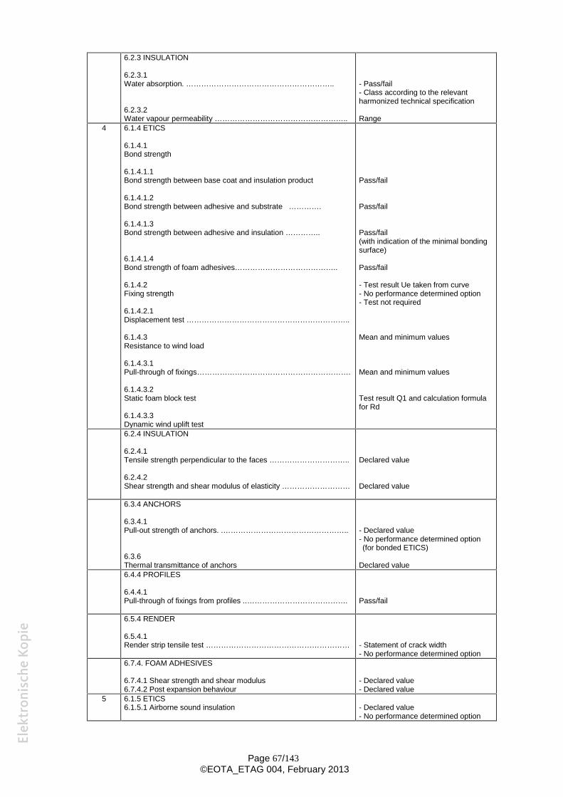
Page 67/143©EOTA_ETAG 004, February 2013
6.2.3 INSULATION
6.2.3.1Water absorption. …………………………………………………..
6.2.3.2Water vapour permeability ……………………………………………..
- Pass/fail- Class according to the relevantharmonized technical specification
Range4 6.1.4 ETICS
6.1.4.1Bond strength
6.1.4.1.1Bond strength between base coat and insulation product
6.1.4.1.2Bond strength between adhesive and substrate ………….
6.1.4.1.3Bond strength between adhesive and insulation …………..
6.1.4.1.4Bond strength of foam adhesives…………………………………..
6.1.4.2Fixing strength
6.1.4.2.1Displacement test ………………………………………………………..
6.1.4.3Resistance to wind load
6.1.4.3.1Pull-through of fixings…………………………………………………….
6.1.4.3.2Static foam block test
6.1.4.3.3Dynamic wind uplift test
Pass/fail
Pass/fail
Pass/fail(with indication of the minimal bondingsurface)
Pass/fail
- Test result Ue taken from curve- No performance determined option- Test not required
Mean and minimum values
Mean and minimum values
Test result Q1 and calculation formulafor Rd
6.2.4 INSULATION
6.2.4.1Tensile strength perpendicular to the faces …………………………..
6.2.4.2Shear strength and shear modulus of elasticity ………………………
Declared value
Declared value
6.3.4 ANCHORS
6.3.4.1Pull-out strength of anchors. .…………………………………………..
6.3.6Thermal transmittance of anchors
- Declared value- No performance determined option(for bonded ETICS)
Declared value6.4.4 PROFILES
6.4.4.1Pull-through of fixings from profiles ..…………………………………. Pass/fail
6.5.4 RENDER
6.5.4.1Render strip tensile test ………………………………………………… - Statement of crack width
- No performance determined option6.7.4. FOAM ADHESIVES
6.7.4.1 Shear strength and shear modulus6.7.4.2 Post expansion behaviour
- Declared value- Declared value
5 6.1.5 ETICS6.1.5.1 Airborne sound insulation - Declared value
- No performance determined option
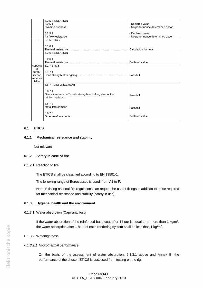
Page 68/143©EOTA_ETAG 004, February 2013
6.2.5 INSULATION6.2.5.1Dynamic stiffness
6.2.5.2Air flow resistance
- Declared value- No performance determined option
- Declared value- No performance determined option
6 6.1.6 ETICS
6.1.6.1Thermal resistance ……………………………………………………… Calculation formula6.2.6 INSULATION
6.2.6.1Thermal resistance ……………………………………………………… Declared value
Aspectsof
durabi-lity andservicea
bility
6.1.7 ETICS
6.1.7.1Bond strength after ageing …………………………………………….. Pass/fail
6.6.7 REINFORCEMENT
6.6.7.1Glass fibre mesh – Tensile strength and elongation of thereinforcing fabric
6.6.7.2Metal lath or mesh
6.6.7.3Other reinforcements
Pass/fail
Pass/fail
Declared value
6.1 ETICS
6.1.1 Mechanical resistance and stability
Not relevant
6.1.2 Safety in case of fire
6.1.2.1 Reaction to fire
The ETICS shall be classified according to EN 13501-1.
The following range of Euroclasses is used: from A1 to F.
Note: Existing national fire regulations can require the use of fixings in addition to those requiredfor mechanical resistance and stability (safety in use).
6.1.3 Hygiene, health and the environment
6.1.3.1 Water absorption (Capillarity test)
If the water absorption of the reinforced base coat after 1 hour is equal to or more than 1 kg/m2,the water absorption after 1 hour of each rendering system shall be less than 1 kg/m2.
6.1.3.2 Watertightness
6.1.3.2.1 Hygrothermal performance
On the basis of the assessment of water absorption, 6.1.3.1 above and Annex B, theperformance of the chosen ETICS is assessed from testing on the rig.
Page 69/143©EOTA_ETAG 004, February 2013
The performance requirements from large scale hygrothermal cyclic testing are that, for eitherthe reinforced base coat (if a part without finishing coat is required) or the ETICS, the followingdefects shall neither occur during, nor at the end of, the test programme:- blistering or peeling of any finishing coat- failure or cracking associated with joints between insulation product boards or profiles fitted
with ETICS- detachment of the render coat- cracking allowing water penetration to the insulating layer (normally ≤ 0,2 mm).
6.1.3.2.2 Freeze-thaw performance
The ETICS is assessed as being freeze-thaw resistant if the water absorption of both thereinforced base coat and the rendering system are less than 0,5 kg/m² after 24 hours (see5.1.3.1).
In all other cases, analysis of results from the tests in 5.1.3.1 is necessary. The performancerequirements for the ETICS are judged to be satisfactory if:- samples show none of the defects described in 6.1.3.2.1and- failure resistances after cycles satisfy the requirements of § 6.1.4.1.1 and/or 6.1.7.1.
6.1.3.3 Impact resistance
The categories given in the following table are only examples of possible uses corresponding todegrees of exposure, this being possible to change from a Member State to another one. Theydo not include an allowance for acts of vandalism.
Table 8: Use examples
Category Description of possible uses
IA zone readily accessible at ground level to the public and vulnerable tohard body impacts but not subjected to abnormally rough use.
II
A zone liable to impacts from thrown or kicked objects, but in publiclocations where the height of the ETICS will limit the size of the impact; orat lower levels where access to the building is primarily to those with someincentive to exercise care.
IIIA zone not likely to be damaged by normal impacts caused by people or bythrown or kicked objects.
The hard body impact with steel ball represents the action from heavy, non deformable objectswhich accidentally hit the ETICS. Based upon the obtained test results the ETICS is assessedas being in category I, II or III in accordance with Table 9 as follows:
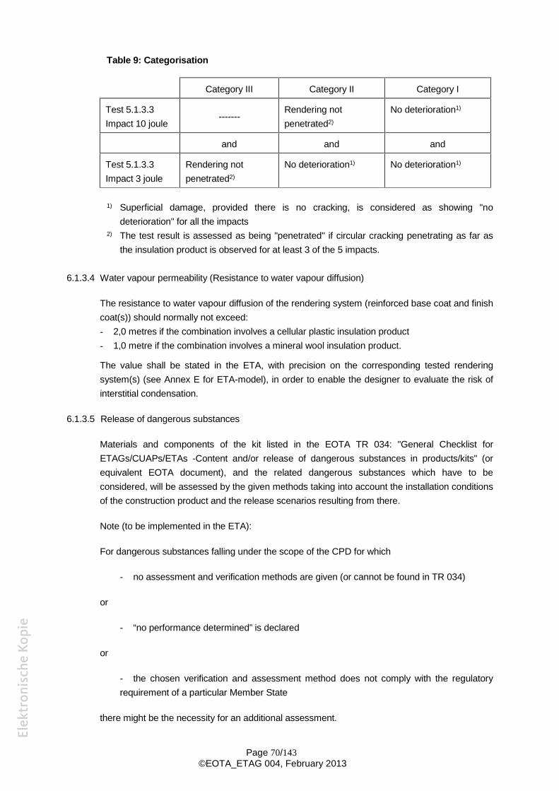
Page 70/143©EOTA_ETAG 004, February 2013
Table 9: Categorisation
Category III Category II Category I
Test 5.1.3.3Impact 10 joule
-------Rendering notpenetrated2)
No deterioration1)
and and and
Test 5.1.3.3Impact 3 joule
Rendering notpenetrated2)
No deterioration1) No deterioration1)
1) Superficial damage, provided there is no cracking, is considered as showing "nodeterioration" for all the impacts
2) The test result is assessed as being "penetrated" if circular cracking penetrating as far asthe insulation product is observed for at least 3 of the 5 impacts.
6.1.3.4 Water vapour permeability (Resistance to water vapour diffusion)
The resistance to water vapour diffusion of the rendering system (reinforced base coat and finishcoat(s)) should normally not exceed:- 2,0 metres if the combination involves a cellular plastic insulation product- 1,0 metre if the combination involves a mineral wool insulation product.
The value shall be stated in the ETA, with precision on the corresponding tested renderingsystem(s) (see Annex E for ETA-model), in order to enable the designer to evaluate the risk ofinterstitial condensation.
6.1.3.5 Release of dangerous substances
Materials and components of the kit listed in the EOTA TR 034: "General Checklist forETAGs/CUAPs/ETAs -Content and/or release of dangerous substances in products/kits" (orequivalent EOTA document), and the related dangerous substances which have to beconsidered, will be assessed by the given methods taking into account the installation conditionsof the construction product and the release scenarios resulting from there.
Note (to be implemented in the ETA):
For dangerous substances falling under the scope of the CPD for which
- no assessment and verification methods are given (or cannot be found in TR 034)
or
- “no performance determined” is declared
or
- the chosen verification and assessment method does not comply with the regulatoryrequirement of a particular Member State
there might be the necessity for an additional assessment.
Page 71/143©EOTA_ETAG 004, February 2013
6.1.4 Safety in Use
6.1.4.1 Bond strength
6.1.4.1.1 Bond strength between base coat and insulation product
At the end of the test 5.1.4.1.1:- all the test results for resistance after each conditioning of the base coat to the insulation
product shall be at least equal to 0,08* N/mm² (MPa) with cohesive or adhesive rupture,or- the rupture shall occur in the insulation product (cohesive rupture) if the failure resistance
is less than 0,08 N/mm² (MPa).* one single value lower than 0,08 but higher than 0,06 N/mm2 (MPa) is admissible
6.1.4.1.2 Bond strength between adhesive and substrate
At the end of the test 5.1.4.1.2, all the test results for failure resistance after eachconditioning to the substrate shall be at least equal to:- in dry condition: 0.25* N/mm2 (MPa)- after effect of water:
0.08** N/mm2 (MPa) at 2 hours after removing the samples from the water 0.25* N/mm2 (MPa) at 7 days after removing the samples from the water
* one single value lower than 0,25 but higher than 0,20 N/mm2 (MPa) is admissible** one single value lower than 0,08 but higher than 0,06 N/mm2 (MPa) is admissible
6.1.4.1.3 Bond strength between adhesive and insulation product
At the end of the test 5.1.4.1.3:- all the test results for failure resistance after each conditioning of the adhesive to the
insulation product shall be at least equal to the values with adhesive or cohesiverupture indicated in the table below:
Table 10: Requirements for the values of failure resistance
Mode of failure
The minimum failure resistance values after each conditioningin N/mm2 (MPa)
Dry condition
After effect of waterAt 2 hours after removingthe samples from thewater
At 7 days afterremoving the samplesfrom the water
Adhesive rupture 0,08* 0,03 0,08*Cohesive rupture in adhesiveCohesive rupture ininsulation 0,03** no requirement no requirement
* one single value lower than 0,08 but higher than 0,06 N/mm2 (MPa) is admissible** in order to comply with the minimal admissible bonded surface requirement described below
Minimal admissible bonded surface area for bonded ETICS:The minimal bonded surface S, which shall exceed 20%, is calculated as follows:S (%) = [0,03 * 100] / BWhere:- B: minimum failure resistance of the adhesive to the insulation product in dry conditions
for all failure modes expressed in MPa- 0,03 MPa correspond to the minimum requirements
Page 72/143©EOTA_ETAG 004, February 2013
The different bonded surface areas, depending on the possible different failure resistancelinked to the tensile strength perpendicular to the face of the insulation product tested, shallbe indicated in the ETA (see Annex E for ETA-model).
Taking this formula into account, the minimum failure resistance lower than 0,03 MPa wouldlead to a bonded surface higher than 100%. Such an ETICS shall consequently bemechanically fixed.
6.1.4.1.4 Bond strength of foam adhesives
At the end of the tests according to 5.1.4.1.4, all the test results for failure resistance shallbe at least equal to 0.08 N/mm² (MPa). One single value lower than 0,08 but higher than0,06 N/mm2 (MPa) within one series is admissible. For calculation of the minimal bondedsurface S, which shall exceed 40 %, the clause 6.1.4.1.3 applies.
6.1.4.2 Fixing strength (transverse displacement)
6.1.4.2.1 Displacement test
The Ue value and equation for determining L (see § 5.1.4.2.1) as a function of T shall bestated in the ETA.
If no test was performed, no performance determined option shall be stated instead.
6.1.4.3 Wind load resistance of mechanically fixed ETICS
Judging shall either be on the basis of assessing data from "pull through" and "foam block"tests or from a “dynamic wind uplift” test. The test or calculation result Rk shall be mentioned inthe ETA.
The stability of an ETICS is verified for the wind load suction according to the provisions ofEurocode EN 1990.
It is not recommended to calculate using Rpanel or Rjoint values which were determined bytesting of insulation products thicker than 80 mm. These values have to be reported togetherwith information about displacement so that it can be taken into account when assessing windload resistance of an ETICS.
6.1.4.3.1 Pull-through of fixings
The mean and minimal failure load values (in N per fixing) of the fixings in dry conditions and, ifappropriate, in wet conditions shall be stated in the ETA.
The test results are also valid for:
- Insulation product of the same type with higher thickness and/or higher tensilestrength perpendicular to the faces
- Anchors with the same or larger plate diameter and/or the same or higher plateStiffness (see EOTA Technical Report n° 26)
Page 73/143©EOTA_ETAG 004, February 2013
6.1.4.3.2 Static foam block test
The mean and minimal failure load values (in N per fixing) in dry conditions and, if appropriate,in wet conditions shall be stated in the ETA
The test results are also valid for:
- Insulation product of the same type with higher thickness and/or higher tensilestrength perpendicular to the faces
- Anchors with the same or larger plate diameter and the same or higher plateStiffness (see EOTA Technical Report n° 26)
6.1.4.3.3 Dynamic wind uplift test
The Q1 value and the equation for determining the design resistance Rd (see § 5.1.4.3.3)depending on the national safety value shall be stated in the ETA.
6.1.5 Protection against noise
6.1.5.1 Airborne sound insulation
If tests have been performed, single number improvement values ∆RW,heavy, ∆(RW + C)heavy
and ∆(RW + Ctr)heavy or ∆RW,direct, ∆(RW + C)direct and ∆(RW + Ctr)direct calculated usingfollowing formulas:∆RW,direct = RW,with – RW,without
∆(RW + C)direct = (RW,with + Cwith)– (RW,without + Cwithout)∆(RW + Ctr)direct = (RW,with + Ctr,with)– (RW,without + Ctr,without)shall be stated in the ETA together with a detailed description of the tested ETICSconfiguration, including at least:
- type, thickness, air flow resistance (for porous insulation products) and dynamic stiffness ofthe insulation product- description and mass (kg/m²) of the rendering system- types, number and application method of ETICS fixing, percentage of bonded surface- type and characteristics (dimensions, mass (kg/m²), nature, design (drawing)) of substrates(walls)
The following extension rules apply:
- The performance measured may also be used for heavier rendering systems thanthat measured (all other parameters identical).
- The performance measured may also be used for the same type of insulationproduct with lower dynamic stiffness than that measured (all other parametersidentical).
- If the performance has been measured with different thicknesses of insulationproduct (all other parameters identical) the values at an intermediate thickness canbe obtained by linear interpolation.
- The performance measured may also be used for the same type of insulationproduct with greater thickness than that measured (all other parameters identical).
Page 74/143©EOTA_ETAG 004, February 2013
- The performance measured may also be used for an ETICS fixed with fewer fixingsthan that measured (all other parameters identical).
- The performance measured may also be used for an ETICS with lower bondedsurface area than that measured (all other parameters identical).
- The performance measured on the heavy wall (according to the definition in EN ISO10140-5 Annex B) may be used for all other heavy walls (of mass per square metrebetween 150 kg/m² and 400 kg/m²).
If no tests have been performed, ∆RW,heavy, ∆(RW + C)heavy and ∆(RW + Ctr)heavy of -8 dBmay be declared as a deemed to satisfy value.
The NPD option (no performance determined) is applicable.
6.1.6 Energy economy and heat retention
6.1.6.1 Thermal resistance
The overall thermal performance requirements of the wall covered by the ETICS can beassessed by means of data relating to the components being included in the calculationprocedures set out in 5.1.6.1. The calculation procedure addresses thermal bridges.Nevertheless, the minimum thermal resistance of the ETICS shall exceed 1 m2 K/W.
6.1.7 Aspects of durability and serviceability
6.1.7.1 Bond strength after ageing
At the end of the test 5.1.4.1.1 and 5.1.7.1:- the minimum failure resistance value shall be at least 0,08 N/mm2 (MPa) with cohesive or
adhesive rupture.or- the rupture shall occur in the insulation product (cohesive rupture) if failure resistance is less
than 0,08 N/mm² (MPa).
TESTS ON COMPONENTS
6.2 INSULATION PRODUCT
6.2.1 Mechanical resistance and stability
Not relevant for this component.
6.2.2 Safety in case of fire
According to requirements of the harmonized technical specification (ETA according to ETAG orCUAP, hEN) for the relevant insulation product or according to an appropriate CWFT Decision.
6.2.3 Hygiene, health and the environment
6.2.3.1 Water absorption
Page 75/143©EOTA_ETAG 004, February 2013
Because of the possible deterioration in thermal properties resulting from accidental waterpenetration water absorption of the insulation product shall not exceed 1 kg/m2 after 24 hourspartial immersion.
6.2.3.2 Water vapour permeability
The µ-value shall be stated in the ETA.
6.2.4 Safety in Use
6.2.4.1 Tensile strength perpendicular to the faces
The results (minimum value) shall be stated in the ETA.
6.2.4.2 Shear strength and shear modulus of elasticity
For bonded ETICS the insulation product shall fulfil the following minimum requirements (see5.2.4.2):- shear strength fk 0,02 N/mm2
- shear modulus Gm 1,0 N/mm2
The subscript "k" indicates a characteristic value and "m" a mean value. The characteristicvalue is normally determined according to a statistical evaluation as the 5 %-fractile of amechanical property. However, for simplification the minimal value of a test series may be takenas substitute for the 5 %-fractile.
The subscript "" stands for shear (strength). The letter "f" describes a strength property(originally derived from "force").
6.2.5 Protection against noise
6.2.5.1 Dynamic stiffness
The dynamic stiffness shall be stated in the ETA, or reference to the CE marking on the basis ofthe appropriate harmonized technical specification (ETA according to an ETAG or CUAP, hEN)shall be made, as long as these give defined values.
The NPD option (no performance determined) is applicable if no acoustic performance of ETICSis declared.
6.2.5.2 Air flow resistance (only for porous insulation material, e.g. mineral wool)
The air flow resistance shall be stated in the ETA, or reference to the CE marking on the basis ofthe appropriate harmonized technical specification (ETA according to an ETAG or CUAP, hEN)shall be made, as long as these give defined values.
The NPD option (no performance determined) is applicable if no acoustic performance of ETICSis declared.
6.2.6 Energy economy and heat retention
6.2.6.1 Thermal resistance
Page 76/143©EOTA_ETAG 004, February 2013
The R or value of the insulation shall be stated in the ETA, or reference to the CE marking onthe basis of the appropriate harmonized specification (ETA according to ETAG or CUAP, hEN) ismade.
However, the assessment and judgement only concerns insulation product with a maximum -value of 0,065 W/m.K. If insulation product is provided by a composite material, it shall complywith the following:
(W/m.K)0650R
d,
d: thickness of the composite panel (insulation product) (m)R: thermal resistance of the insulation product (m2.K/W)
6.3 ANCHORS
6.3.1 Mechanical resistance and stability
Not relevant for this component.
6.3.2 Safety in case of fire
Not relevant for this component.
6.3.3 Hygiene, health and the environment
Not relevant for this component.
6.3.4 Safety in Use
6.3.4.1 Pull-out strength of anchor
The characteristic strength of the anchor shall be stated in the ETA or reference shall be madeto the ETA for the anchor.
6.3.5 Protection against noise
Not relevant for this component.
6.3.6 Energy economy and heat retention
Ascertained values shall be taken into account within evaluation according to cl. 6.1.6.1.
6.4 PROFILES AND THEIR FIXINGS
6.4.1 Mechanical resistance and stability
Not relevant for this component.
6.4.2 Safety in case of fire
Not relevant for this component.
6.4.3 Hygiene, health and the environment
Page 77/143©EOTA_ETAG 004, February 2013
Not relevant for this component.
6.4.4 Safety in Use
6.4.4.1 Pull through resistance of fixings from profiles
The lowest pull through resistance shall be at least equal to 500 N.
6.4.5 Protection against noise
Not relevant for this component.
6.4.6 Energy economy and heat retention
Not relevant for this component.
6.5 RENDER
6.5.1 Mechanical resistance and stability
Not relevant for this component.
6.5.2 Safety in case of fire
Not relevant for this component.
6.5.3 Hygiene, health and the environment
Not relevant for this component.
6.5.4 Safety in use
6.5.4.1 Render Strip Tensile Test
The characteristic crack width wrk at completed cracking shall be given in the ETA for the warpand weft direction of the rendering system with reference to the evaluation method applied.
For organic rendering systems without observed cracking the mean values of the elongation atrupture εru and the respective ultimate load Nru shall be given in the ETA.
6.5.5 Protection against noise
Not relevant for this component.
6.5.6 Energy economy and heat retention
Not relevant for this component.
6.6 REINFORCEMENT
6.6.1 Mechanical resistance and stability
Not relevant for this component.
Page 78/143©EOTA_ETAG 004, February 2013
6.6.2 Safety in case of fire
Not relevant for this component.
6.6.3 Hygiene, health and the environment
Not relevant for this component.
6.6.4 Safety in use
Not relevant for this component.
6.6.5 Protection against noise
Not relevant for this component.
6.6.6 Energy economy and heat retention
Not relevant for this component.
6.6.7 Aspects of durability and serviceability
6.6.7.1 Glass fibre mesh - Tensile strength and elongation* of the reinforcing fabric
After ageing, the residual strength shall be at least:- 50% of the strength in the as-delivered state- and 20 N/mm.
After ageing, the residual strength of the reinforced meshes shall be at least:- 40% of the strength in the as-delivered state- and 20 N/mm.
6.6.7.2 Metal lath or mesh
Metal lath or mesh reinforcement can be made of galvanised steel or austenitic stainless steel.For galvanised laths, the minimum thickness of the zinc coat shall be 20 µm ( 275 g/m2), andgalvanising shall take place after welding the lath.
6.6.7.3 Other reinforcements
Requirements are to be set depending on the type of other reinforcements.
6.7 FOAM ADHESIVES
6.7.1 Mechanical resistance and stability
Not relevant for this component.
6.7.2 Safety in case of fire
Not relevant for this component.
6.7.3 Hygiene, health and the environment
Page 79/143©EOTA_ETAG 004, February 2013
Not relevant for this component.
6.7.4 Safety in use
6.7.4.1 Shear strength and shear modulus
The results shall be stated in the ETA.
6.7.4.2 Post expansion behaviour
The results shall be stated in the ETA.
6.7.5 Protection against noise
Not relevant for this component.
6.7.6 Energy economy and heat retention
Not relevant for this component.
6.7.7 Aspects of durability and serviceability
Not relevant for this component.
Page 80/143©EOTA_ETAG 004, February 2013
ASSUMPTIONS AND RECOMMENDATIONS UNDER WHICH THE FITNESS FORUSE OF THE PRODUCT IS ASSESSED
7.0 GENERAL
The assessment of an ETICS according to this ETAG is based on an assumed way of design,installation and execution, transport and storage, use, maintenance and repair. Especially design,installation and execution are to be in conformity with national documents. However, thesedocuments and the level of their implementation in Member States’ legislation are different. Thischapter summarizes how information introduced in ETAs and related documents is intended to beused in the construction process and gives advice to all parties interested when normativedocuments are missing.
7.1 DESIGN OF THE WORKS
7.1.1 Substrate inspection
A design of an ETICS shall be preceded by a substrate inspection. Substrate characteristics areparticularly important for the design in terms of fixing the ETICS and the ETICS permeability towater vapour (the ETICS should generally have higher permeability than the substrate). Based onthe survey, it shall also be determined if and how the substrate will be prepared prior toapplication of the ETICS. Old constructions may require surface preparation, such as existingpainting or plaster removal where load transfer to the wall cannot be assumed.
The wall, on which the ETICS is applied, shall be sufficiently airtight.
7.1.2 ETICS design
The design and/or other relevant documentation for the construction site shall clearly define theETICS composition, including ETICS specific components. Possible combinations of componentsand their use shall be in accordance with the ETA and the ETICS manufacturer’s documentation.
Characteristics of the ETICS and the components shall be specified in accordance with relevantharmonized technical specifications (ETA for the ETICS, harmonized standard for thermalinsulation product, etc.).
The details (connections, joints, etc.), shall be designed to prevent water penetration. It should bepossible to attach additional structural elements (pipes, etc) to the substrate without damaging theintegrity of the ETICS so that its performance is reduced.
The design and/or other relevant documentation for the construction site should at least includeconditions or an assessment in relation to the essential requirements for construction, asdescribed below. The design documentation shall comply with any applicable national regulatoryprovisions.
7.1.2.1 Mechanical resistance and stability
The additional load caused by an ETICS does not normally mean a significant risk in terms of theload-bearing capacity of the construction, but it is recommended to take it into account.
7.1.2.2 Safety in case of fire
Page 81/143©EOTA_ETAG 004, February 2013
The ETICS shall conform to national requirements for reaction to fire depending on the building towhich it is applied (particularly critical are the type, height and location of the building). SomeMember States have additional requirements for fire safety in regulatory provisions forconstruction and these shall be met, too.
7.1.2.3 Hygiene, health and the environment
The thermal calculation shall confirm that the ETICS complies with national requirementsregarding hygiene of the indoor environment, especially water vapour condensation(requirements for interior surface temperature, dew point, etc.) which shall be avoided.
Based on the anticipated exposure of the ETICS to human activity in its vicinity, it isrecommended to consider category I, II or III of impact resistance when designing the ETICS.
7.1.2.4 Safety in use
The method of fixing of an ETICS to the substrate shall be laid down in the design and/or otherrelevant documentation for the construction site. It is based on substrate characteristics andmechanical properties of the ETICS. The methods of fixing can be combined, but their effectscannot be added.
Bonded ETICS: If national regulations do not specify otherwise, this method of fixing can beproposed only in cases where for the specific ETICS the bonded surface S is less than or equal to100 % according to the formula specified in clause 6.1.4.1.3 of this ETAG. It is also necessary toevaluate properties of the substrate and bond strength of an adhesive to the substrate on thebasis of national regulations. If national requirements are not established, it is recommended torequest the minimum value of bond strength of the adhesive to the substrate of 0,08 MPa whentested in-situ.
The shear strength of the insulation product shall meet requirements of the chapter 6.2.4.2 of thisETAG.
Mechanically fixed ETICS: If national regulations do not specify further assessment, it isnecessary to evaluate at least resistance to effects of wind suction on the surface of the specificbuilding, which are determined according to Eurocode EN 1990. To calculate the wind suctionresistance, the following shall be considered:
a) the wind load resistance of mechanically fixed ETICS as laid down in the ETA for the ETICS,or in other documents if specified in national regulations and
b) the pull-out strength of the fixing from the substrate as laid down in the ETA for the ETICS orin the document referenced in the ETA for the ETICS (job site testing may be required there).
In addition, if the reinforced base coat is not mechanically fixed to the insulation product or thesubstrate, the bond strength between base coat and insulation product shall be taken intoaccount when assessing the ETICS resistance to wind suction.
7.1.2.5 Protection against noise
Page 82/143©EOTA_ETAG 004, February 2013
If a national regulation requires assessing the ETICS contribution to the airborne sound insulationof a building envelope, the values declared in the ETA are used with regard to the use conditionsof the declared values (ETICS composition, properties of the construction).
7.1.2.6 Energy economy and heat retention
The heat transfer through an insulated wall is assessed according to national regulations. Theinsulation product properties declared according to the relevant technical specification are used incalculation, if national regulations do not specify otherwise.
7.1.2.7 Aspects of durability and serviceability
The assessment of an ETICS according to this ETAG is based on the assumed working life of 25years. This shall be taken into account when designing details of the ETICS.
7.2 EXECUTION OF THE WORKS
The works shall be executed by trained installers.
Any relevant documentation for the construction site shall include a detailed description of theinstallation of the ETICS, specifying the required procedures (preparation of substrates, especiallyin the case of old walls, bonding, anchoring, execution of a base coat and a finishing coat,drawings, etc.), their sequence and timing of operations, the methods of application (machinery,equipment, tools), amounts of materials used, drying times, as well as temperature and thesubstrate's humidity limits for use.
Installation of the ETICS shall comply with national regulations, design and relevantdocumentation for the construction site.
7.2.1 Preparation of the substrate
The substrate has to be strong, dry and free of loose material. It shall not be significantly moist orpermanently damp. Significant moisture shall be reduced by appropriate action prior to ETICSapplication so that the cause is eliminated or sufficiently limited.
7.2.2 Basic principles of ETICS installation
– Rows of insulation products are positioned so that vertical joints are staggered.
– Joints between insulation products shall be tightly butted and shall not contain render.
– Incorrectly installed anchors shall be removed and replaced by new ones in the vicinity.
– The installed insulation products shall provide a flush surface to ensure the application of aneven thickness of reinforced base coat.
– The insulation product shall be protected from the environment before it begins to degrade.
– The thickness of the reinforced base coat and the finishing coat shall be as specified in theETA.
– Climatic conditions and time intervals shall be met in the application of layers.
Page 83/143©EOTA_ETAG 004, February 2013
– The reinforcement shall be fully embedded in the base coat, having sufficient cover.Reinforcement strips shall overlap.
– The execution of the ETICS shall be limited to facades with a length L or with a distancebetween expansion joints less than L as determined in 5.1.4.2.1 and 6.1.4.2.1.
7.3 MAINTENANCE AND REPAIR OF THE WORKS
The finishing coat shall normally be maintained in order to fully preserve the ETICS performance.
Maintenance includes at least:
– visual inspection of the ETICS
– repairs to localized damaged areas due to accidents,
– the aspect maintenance with products adapted and compatible with the ETICS (possibly afterwashing or ad hoc preparation).
Necessary repairs should be performed as soon as the need has been identified.
It is important to be able to carry out maintenance as far as possible using readily availableproducts and equipment, without spoiling the appearance. Only products which are compatiblewith the ETICS shall be used.
Page 84/143©EOTA_ETAG 004, February 2013
S e c t i o n t h r e e :A T T E S T A T I O N O F C O N F O R M I T Y
8 ATTESTATION AND EVALUATION OF CONFORMITY
8.1 EC DECISIONS
The systems of attestation of conformity specified by the European Commission Decisions aresystem 1 or 2 + described in Council Directive (89/106/EEC) Annex III, 2 (i) or 2 (ii) firstpossibility respectively and detailed as follows:
According to the decision of the European Commission 97/556/EC the system of attestation ofconformity 2+ applies.
In addition, according to the decision of the European Commission 2001/596/EC, the systems ofattestation of Conformity 1 and 2+ apply to ETICS with regard to reaction to fire
The systems of attestation of conformity referred to above are defined as follows:
System 1 for ETICS for which the following is valid:- intended use in external walls subject to reaction to fire regulations,- reaction to fire classes A1, A2 B or C,- made of materials for which a clearly identifiable stage in the production process results in
an improvement of the reaction to fire classification (e.g. an addition of fire retardants or alimiting of organic material),
is described in Council Directive (89/106/EEC) Annex III, 2 (i) and is detailed as follows:
Certification of the conformity of the product by a Notified Body on the basis of:
a) Tasks of the manufacturer- factory production control,- further testing of samples taken at the factory by the manufacturer in accordance with a
prescribed control plan.
b) Tasks of the approved Notified Body- initial type-testing of the product (reaction to fire),- initial inspection of the factory and of factory production control,- continuous surveillance, assessment and approval of factory production control.
System 2+ for all other ETICS is detailed as follows:
Declaration of conformity of the product by the manufacturer on the basis of:
Page 85/143©EOTA_ETAG 004, February 2013
a) Tasks of the manufacturer- initial type-testing of the product,- factory production control.- testing of samples taken at the factory in accordance with a prescribed control plan
b) Tasks of the approved Notified BodyCertification of factory production control on the basis of:- initial inspection of factory and factory production control,- continuous surveillance, assessment and approval of factory production control.
8.2 TASKS AND RESPONSIBILITIES OF THE MANUFACTURER AND NOTIFIED BODIES
8.2.1 Tasks of the manufacturer
8.2.1.1 Factory production control
The manufacturer shall exercise permanent internal control of production. All the elements,requirements and provisions adopted by the manufacturer shall be documented in asystematic manner in the form of written policies and procedures. This production controlsystem shall ensure that the product is in conformity with the European Technical Approval(ETA).
In case of kit production, the factory indicated by the manufacturer is a place which isresponsible for properties of all the components, securing conformity of the kit withrequirements of the ETA, regardless of whether the components are physically produced inthe place or not.
Manufacturers having an FPC system which complies with EN ISO 9001 and which addressesthe requirements of an ETA are recognized as satisfying the FPC requirements of theDirective.
8.2.1.2 Testing of samples taken at the factory (only for system 1)
The tests shall only be carried out on the final product or samples which are representative ofthe final product.
Both large and small companies produce the various components of the ETICS and there is awide variation in the volume and in the production processes. Therefore a precise control plancan only be set up on a case by case basis.
8.2.1.3 Declaration of Conformity
When all the criteria of the Conformity Attestation are satisfied the manufacturer shall make aDeclaration of Conformity.
8.2.2 Tasks of the manufacturer or the approved Notified Body
8.2.2.1 Initial Type Testing
Approval tests will have been conducted by the Approval Body or under its responsibility(which may include a proportion conducted by an approved laboratory or by the manufacturer,witnessed by the Approval Body) in accordance with section 5 of this ETAG. The Approval
Page 86/143©EOTA_ETAG 004, February 2013
Body will have assessed the results of these tests in accordance with section 6 of this ETAG,as part of the ETA issuing procedure.
These tests can be used for the purposes of Initial Type Testing(1).
For system 1, this work shall be validated by the Notified Body for Certificate of Conformitypurposes.
For system 2+, this work shall be taken over by the manufacturer for Declaration of Conformitypurposes.
8.2.3 Tasks of the approved Notified Body
8.2.3.1 Assessment of the factory production control system - initial inspection and continuoussurveillance
Assessment of the factory production control system is the responsibility of the Notified Body.
An initial assessment of the factory shall be carried out to demonstrate that the factoryproduction control is in conformity with the ETA and any subsidiary information. It may benecessary to visit other detached production places.
Subsequently continuous surveillance of factory production control is necessary to ensurecontinuing conformity with the ETA.
It is recommended that surveillance inspections be conducted at least twice a year or at leastonce a year for manufacturers having an FPC system which complies with EN ISO 9001, afterverification that the manufacturing of the ETICS components is covered by this standard.
8.2.3.2 Certification
The Notified Body shall issue:Certification of Conformity of product (for system 1)Certification of Factory Production Control (for system 2+).
8.3 DOCUMENTATION
In order to help the Notified Body to make an evaluation of conformity, the Approval Bodyissuing the ETA shall supply the information detailed below. This information together with therequirements given in EC Guidance Paper B will generally form the basis on which the factoryproduction control (FPC) is assessed by the Notified Body.
This information shall initially be prepared or collected by the Approval Body and shall beagreed with the manufacturer. The following gives guidance on the type of information required:
1) The ETASee chapter 9 of this Guideline.If confidential information is required, this shall be in a separate part of the ETA (which doesnot accompany the ETICS) or the ETA shall make reference to the manufacturer’s technicaldocumentation which contains such information.
2) Basic manufacturing processThe basic manufacturing process shall be described in sufficient detail to support the
(1) In this respect Approval Bodies shall be able to have open arrangements with relevant Approved Bodies toavoid duplication, respecting each others responsibilities.
Page 87/143©EOTA_ETAG 004, February 2013
proposed FPC methods.The different components of ETICS are generally manufactured using conventionaltechniques. Any critical process or treatment of the components which affects performanceshall be highlighted.
3) Product and materials specificationsThese may include:- detailed drawings (including manufacturing tolerances),- incoming (raw) materials specifications and declarations,- references to European and/or international standards,- manufacturer’s data sheets.
4) Control plan (as part of FPC)The manufacturer and the Approval Body issuing the ETA shall agree an FPC control plan.This shall be deposited with the Approval Body in documentation which accompanies theETA.An agreed FPC control plan is necessary as current standards relating to managementsystems (Guidance Paper B, EN ISO 9001, ...), do not ensure that the product specificationremains unchanged and they cannot address the technical validity of the type or frequencyof checks/tests.The validity of the type and frequency of checks/tests conducted during production and onthe final product shall be considered. This will include the checks conducted duringmanufacture on properties that cannot be inspected at a later stage and for checks on thefinal product.The list is given as an example in Table 11 for the components generally used in ETICS. Itshall be adapted case by case in order to take into account the risk of proper variation toeach component.These will normally include (see Table 11):
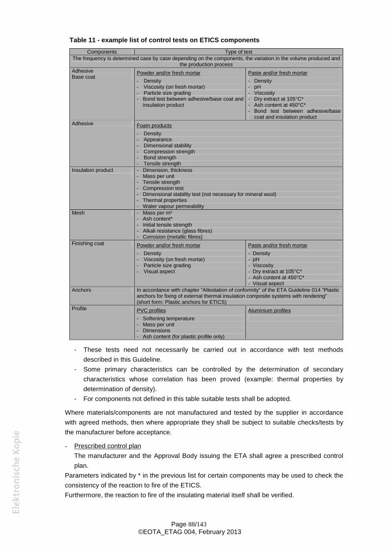
Page 88/143©EOTA_ETAG 004, February 2013
Table 11 - example list of control tests on ETICS componentsComponents Type of test
The frequency is determined case by case depending on the components, the variation in the volume produced andthe production process
AdhesiveBase coat
Powder and/or fresh mortar- Density- Viscosity (on fresh mortar)- Particle size grading- Bond test between adhesive/base coat and
insulation product
Paste and/or fresh mortar- Density- pH- Viscosity- Dry extract at 105°C*- Ash content at 450°C*- Bond test between adhesive/base
coat and insulation productAdhesive Foam products
- Density- Appearance- Dimensional stability- Compression strength- Bond strength- Tensile strength
Insulation product - Dimension, thickness- Mass per unit- Tensile strength- Compression test- Dimensional stability test (not necessary for mineral wool)- Thermal properties- Water vapour permeability
Mesh - Mass per m²- Ash content*- Initial tensile strength- Alkali resistance (glass fibres)- Corrosion (metallic fibres)
Finishing coat Powder and/or fresh mortar- Density- Viscosity (on fresh mortar)- Particle size grading- Visual aspect
Paste and/or fresh mortar- Density- pH- Viscosity- Dry extract at 105°C*- Ash content at 450°C*- Visual aspect
Anchors In accordance with chapter "Attestation of conformity" of the ETA Guideline 014 "Plasticanchors for fixing of external thermal insulation composite systems with rendering”(short form: Plastic anchors for ETICS)
Profile PVC profiles- Softening temperature- Mass per unit- Dimensions- Ash content (for plastic profile only)
Aluminium profiles
- These tests need not necessarily be carried out in accordance with test methodsdescribed in this Guideline.
- Some primary characteristics can be controlled by the determination of secondarycharacteristics whose correlation has been proved (example: thermal properties bydetermination of density).
- For components not defined in this table suitable tests shall be adopted.
Where materials/components are not manufactured and tested by the supplier in accordancewith agreed methods, then where appropriate they shall be subject to suitable checks/tests bythe manufacturer before acceptance.
- Prescribed control planThe manufacturer and the Approval Body issuing the ETA shall agree a prescribed controlplan.
Parameters indicated by * in the previous list for certain components may be used to check theconsistency of the reaction to fire of the ETICS.Furthermore, the reaction to fire of the insulating material itself shall be verified.
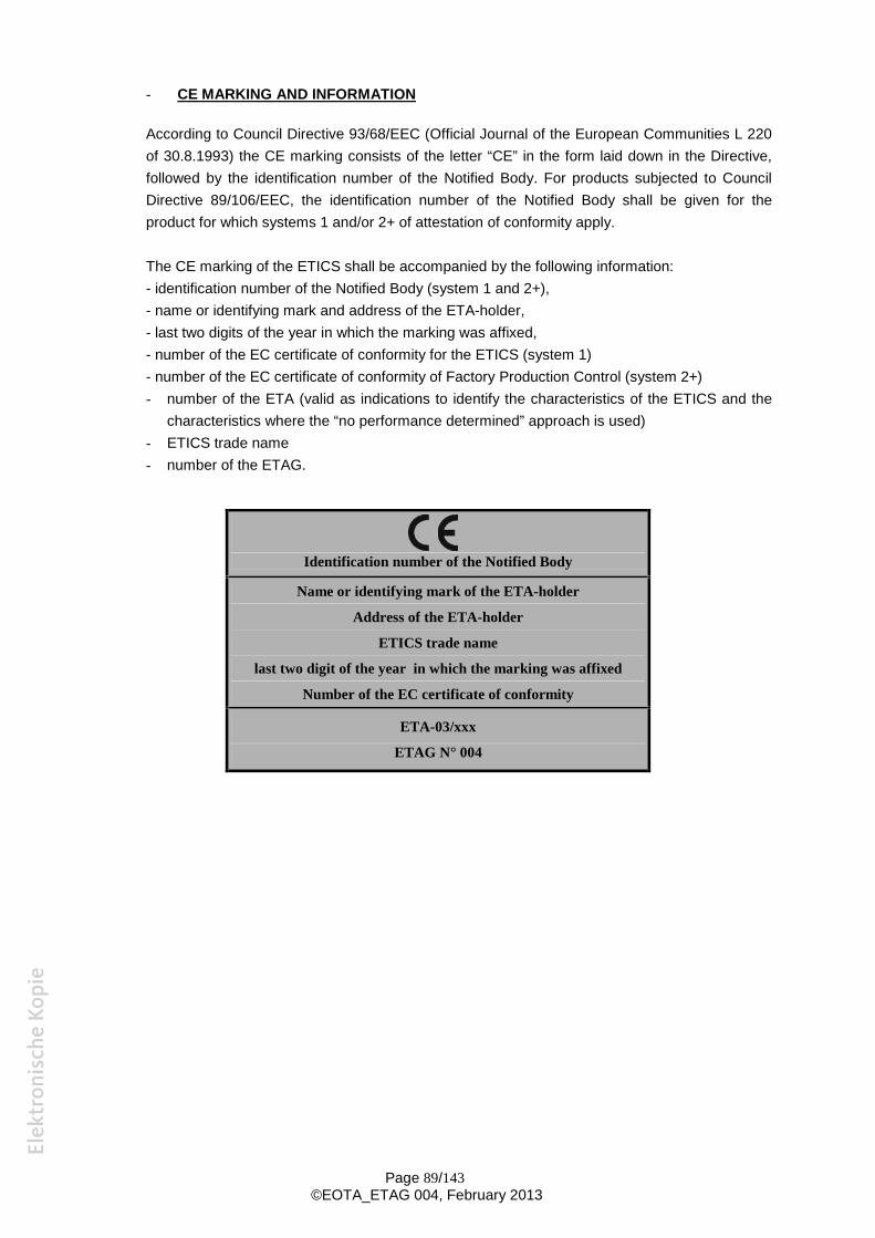
Page 89/143©EOTA_ETAG 004, February 2013
- CE MARKING AND INFORMATION
According to Council Directive 93/68/EEC (Official Journal of the European Communities L 220of 30.8.1993) the CE marking consists of the letter “CE” in the form laid down in the Directive,followed by the identification number of the Notified Body. For products subjected to CouncilDirective 89/106/EEC, the identification number of the Notified Body shall be given for theproduct for which systems 1 and/or 2+ of attestation of conformity apply.
The CE marking of the ETICS shall be accompanied by the following information:- identification number of the Notified Body (system 1 and 2+),- name or identifying mark and address of the ETA-holder,- last two digits of the year in which the marking was affixed,- number of the EC certificate of conformity for the ETICS (system 1)- number of the EC certificate of conformity of Factory Production Control (system 2+)- number of the ETA (valid as indications to identify the characteristics of the ETICS and the
characteristics where the “no performance determined” approach is used)- ETICS trade name- number of the ETAG.
Identification number of the Notified Body
Name or identifying mark of the ETA-holder
Address of the ETA-holder
ETICS trade name
last two digit of the year in which the marking was affixed
Number of the EC certificate of conformity
ETA-03/xxx
ETAG N° 004
Page 90/143©EOTA_ETAG 004, February 2013
S e c t i o n f o u r :E T A C O N T E N T
9 THE ETA CONTENT
9.1 THE ETA CONTENT
European Technical Approvals issued on the basis of this ETAG shall be in accordance with theannex E (ETA model).
Page 91/143©EOTA_ETAG 004, February 2013
A n n e x A :C O M M O N T E R M I N O L O G Y
A N D A B B R E V I A T I O N S
A.1 Works and products
A.1.1 Construction works (and parts of works) (often simply referred to as "works") (ID 1.3.1)
Everything that is constructed or results from construction operations and is fixed to theground. (This covers both building and civil engineering works, and both structural andnon-structural elements).
A.1.2 Construction products (often simply referred to as "products") (ID 1.3.2)
Products which are produced for incorporation in a permanent manner in the works andplaced as such on the market.
(The term includes materials, elements and components of prefabricated ETICS orinstallations).
A.1.3 Incorporation (of products in works) (ID 1.3.2)
Incorporation of a product in a permanent manner in the works means that:- its removal reduces the performance capabilities of the works, and- that the dismantling or the replacement of the product are operations which involve
construction activities.
A.1.4 Intended use (ID 1.3.4)
Role(s) that the product is intended to play in the fulfilment of the Essential Requirements.
(N.B.: This definition covers only the intended use as far as relevant for the CPD).
A.1.5 Execution (ETAG-format)
Used in this document to cover all types of incorporation techniques such as installation,assembling or incorporation.
A.1.6 System (EOTA/TB guidance)
Part of work realised by:- particular combination of a set of defined products, and- particular design methods for the ETICS, and/or- particular execution procedures.
Page 92/143©EOTA_ETAG 004, February 2013
A.2 Performances
A.2.1 Fitness for intended use (of products) (CPD 2.1)
Means that the products have such characteristics that the works in which they are intended tobe incorporated, assembled, applied or installed, can, if properly designed and built, satisfy theEssential Requirements.
(N.B: This definition covers only the intended fitness for intended use as far as relevant for theCPD)
A.2.2 Serviceability (of works)
Ability of the works to fulfill their intended use and in particular the Essential Requirementsrelevant for this use.
The products shall be suitable for construction works which (as a whole and in their separateparts) are fit for their intended use, subject to normal maintenance, be satisfied for aneconomically reasonable working life. The requirements generally concern actions which areforeseeable (CPD Annex I preamble).
A.2.3 Essential Requirements (for works)
Requirements applicable to works, which may influence the technical characteristics of aproduct, and are set out in terms of objectives in the CPD, Annex I (CPD, art. 3.1).
A.2.4 Performance (of works, parts of works or products) (ID 1.3.7)
The quantitative expression (value, grade, class or level) of the behaviour of the works, partsof works or of the products, for an action to which it is subject or which it generates under theintended service conditions (works or parts of works) or intended use conditions (products).
As far as practicable the characteristics of products, or groups of products, should bedescribed in measurable performance terms in the technical specifications and guidelines forETA. Methods of calculation, measurement, testing (where possible), evaluation of siteexperience and verification, together with compliance criteria shall be given either in therelevant technical specifications or in references called up in such specifications.
A.2.5 Actions (on works or parts of the works) (ID 1.3.6)
Service conditions of the works which may affect the compliance of the works with theEssential Requirements of the Directive and which are brought about by agents (mechanical,chemical, biological, thermal or electro-magnetic) acting on the works or parts of the works.
Interactions between various products within a work are considered as "actions".
A.2.6 Classes or levels (for Essential Requirements and for related product performances))(ID 1.2.1)
A classification of product performance(s) expressed as a range of requirement levels of theworks, determined in the ID's or according to the procedure provided for in art. 20.2 a of theCPD.
Page 93/143©EOTA_ETAG 004, February 2013
A.3 ETAG-Format
A.3.1 Requirements (for works) (ETAG-format 4)
Expression and application, in more detail and in terms applicable to the scope of theguideline, of the relevant requirements of the CPD given concrete form in the ID's and furtherspecified in the mandate, for works or parts of the works, taking into account the durability andserviceability of the works.
A.3.2 Methods of verification (for products) (ETAG-format 5)
Verification methods are used to determine the performance of the products in relation to therequirements for the works (calculations, tests, engineering knowledge, evaluation of siteexperience, etc...).
This verification methods are related only to the assessment of, and for judging the fitness for,use. Verification methods for particular designs of works are called here "project testing", foridentification of products are called "identification testing", for surveillance of execution orexecuted works are called "surveillance testing", and for attestation of conformity are called"AC-testing".
A.3.3 Specifications (for products) (ETAG-format 6)
Transposition of the requirements into precise and measurable (as far as possible andproportional to the importance of the risk) or qualitative terms, related to the products and theirintended use.
The satisfaction of the specifications is deemed to satisfy the fitness for use of the productsconcerned.
Specifications may also be formulated with regard to the verification of particular designs, foridentification of products, for surveillance of execution or executed works and for attestation ofconformity, when relevant.
A.4 Working life
A.4.1 Working life (of works or parts of the works) (ID 1.3.5 [1])
The period of time during which the performance will be maintained at a level compatible withthe fulfilment of the Essential Requirements.
A.4.2 Working life (of products)
The period of time during which the performances of the product are maintained, under thecorresponding service conditions, at a level compatible with the intended use conditions.
A.4.3 Economically reasonable working life (ID 1.3.5 [2])
Working life which takes into account all relevant aspects, such as costs of design,construction and use, costs arising from hindrance of use, risks and consequences of failure ofthe works during its working life and cost of insurance covering these risks, planned partialrenewal, costs of inspections, maintenance, care and repair, costs of operation andadministration, of disposal and environmental aspects.
Page 94/143©EOTA_ETAG 004, February 2013
A.4.4 Maintenance (of works) (ID 1.3.3 [1])
A set of preventive and other measures which are applied to the works in order to enable theworks to fulfill all its functions during its working life. These measures include cleaning,servicing, repainting, repairing, replacing parts of the works where needed, etc.
A.4.5 Normal maintenance (of works) (ID 1.3.3 [2])
Maintenance, normally including inspections, which occurs at a time when the cost of theintervention which has to be made is not disproportionate to the value of the part of the workconcerned, consequential costs (e.g. exploitation) being taken into account.
A.4.6 Durability (of products)
Ability of the product to contribute to the working life of the works by maintaining itsperformances, under the corresponding service conditions, at a level compatible with thefulfilment of the Essential Requirements by the works.
A.5 Conformity
A.5.1 Evaluation of conformity (of products)
Provisions and procedures as laid down in the CPD and fixed according to the directive,aiming to ensure that, with acceptable probability, the specified performance of the product isachieved by the ongoing production.
A.5.2 Identification (of a product)
Product characteristics and methods for their verification, allowing to compare a given productwith the one that is described in the technical specification.
A.6 Approval and Notified Body
A.6.1 Approval Body
Body notified in accordance with Article 10 of the CPD, by an EU Member State or by an EFTAState (contracting party to the EEA Agreement), to issue European Technical Approvals in (a)specific construction product area(s). All such bodies are required to be members of theEuropean Organisation for Technical Approvals (EOTA), set up in accordance with Annex II.2 ofthe CPD.
A.6.2 Notified Body (also known as Approved Body)
Body nominated in accordance with Article 18 of the CPD, by an EU Member Sate or by anEFTA State (contracting party to the EEA Agreement), to perform specific tasks in theframework of the Attestation of Conformity decision for specific construction products(certification, inspection or testing). All such bodies are automatically members of the Group ofNotified Bodies.
Page 95/143©EOTA_ETAG 004, February 2013
A.7 Abbreviations
A.7.1 Abbreviations concerning the Construction Products Directive
AC: Attestation of ConformityEC: European CommissionCEN: Comité Européen de Normalisation (European Committee for Standardization)CPD: Construction Products DirectiveEFTA: European Free Trade AssociationEN: European StandardsER: Essential RequirementsFPC: Factory Production ControlID: Interpretative Documents of the CPDISO: International Standardisation OrganisationSCC: Standing Committee for Construction of the EC
A.7.2 Abbreviations concerning approval
EOTA: European Organisation for Technical ApprovalsETA: European Technical ApprovalETAG: European Technical Approval GuidelineETICS: External Thermal Insulation Composite System(s)TB: EOTA-Technical boardUEAtc: Union Européenne pour l'Agrément technique dans la construction (European Union
of Agrement)
A.7.3 General abbreviations
TC: Technical CommitteeWG: Working Group
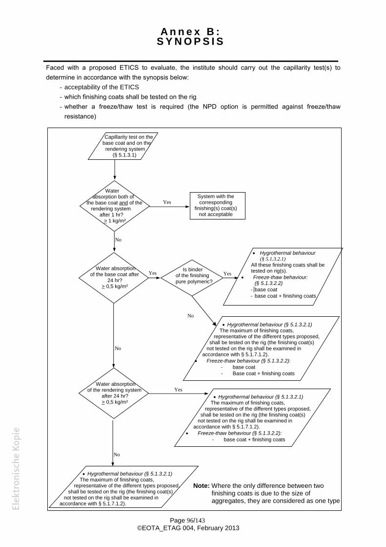
Page 96/143©EOTA_ETAG 004, February 2013
A n n e x B :S Y N O P S I S
Faced with a proposed ETICS to evaluate, the institute should carry out the capillarity test(s) todetermine in accordance with the synopsis below:
- acceptability of the ETICS- which finishing coats shall be tested on the rig- whether a freeze/thaw test is required (the NPD option is permitted against freeze/thaw
resistance)
Note: Where the only difference between twofinishing coats is due to the size ofaggregates, they are considered as one type
Capillarity test on thebase coat and on therendering system
(§ 5.1.3.1)
Is binderof the finishingpure polymeric?
Water absorptionof the base coat after
24 hr?> 0,5 kg/m²
Hygrothermal behaviour(§ 5.1.3.2.1)
All these finishing coats shall betested on rig(s).
Freeze-thaw behaviour:(§ 5.1.3.2.2)
- base coat- base coat + finishing coats
Hygrothermal behaviour (§ 5.1.3.2.1)The maximum of finishing coats,
representative of the different types proposed,shall be tested on the rig (the finishing coat(s)
not tested on the rig shall be examined inaccordance with § 5.1.7.1.2).
Freeze-thaw behaviour (§ 5.1.3.2.2):- base coat- Base coat + finishing coats
Hygrothermal behaviour (§ 5.1.3.2.1)The maximum of finishing coats,
representative of the different types proposed,shall be tested on the rig (the finishing coat(s)
not tested on the rig shall be examined inaccordance with § 5.1.7.1.2).
System with thecorresponding
finishing(s) coat(s)not acceptable
Waterabsorption both of
the base coat and of therendering system
after 1 hr?> 1 kg/m²
Yes
Yes Yes
Yes
No
No
No
No
Water absorptionof the rendering system
after 24 hr?> 0,5 kg/m²
Hygrothermal behaviour (§ 5.1.3.2.1)The maximum of finishing coats,
representative of the different types proposed,shall be tested on the rig (the finishing coat(s)
not tested on the rig shall be examined inaccordance with § 5.1.7.1.2).
Freeze-thaw behaviour (§ 5.1.3.2.2):- base coat + finishing coats
Page 97/143©EOTA_ETAG 004, February 2013
A n n e x C :M E T H O D S R E L A T E D T O T H E
I D E N T I F I C A T I O N O F T H E E T I C SC O M P O N E N T S
C METHODS RELATED TO THE IDENTIFICATION OF THE ETICS COMPONENTS
Additional identification tests to the ones identified in chapter 5 with*.
These test methods shall be applied by anybody who carries out the identification tests of thecomponents used in the approval tests.
In some cases, such as where a trade name is sufficient to identify a component and itscharacteristics, the identification tests in this annex do not need to be performed as long as thecomponent is identified by means such as its trade name. This possibility is to be decided by theApproval Body.
C.1 Adhesives (except for foam adhesives), base coats, key coats and finishing coats
C.1.1 Product as delivered
The following tests are performed on homogenised and unmodified products.
C.1.1.1 Density
Pastes and liquids:This is measured at (23 ± 2)°C in a 100 cm3 or 1000 cm3 cylinder.
Powders:This is measured at (23 2)°C in a 500 cm³ cylinder.
Method of operation:The results are recorded after maximum packing down on a vibrating table and levelling of thesurface.The results are expressed in kg/m3 (mean value of 3 tests).
C.1.1.2 Dry extract (only pastes and liquids)
C.1.1.2.1 Lime and polymer based products
This is determined after placing the sample in a ventilated oven set at (105 ± 5)°C until aconstant mass is obtained.
The mass is regarded as constant if the difference in mass between two successiveweighings, one hour apart, does not exceed 0,1 g.
Initial weighing for testing:- 2 g for liquid products (impression, etc ...),- 5 g for products in paste form.The results are expressed as a percentage relative to the initial mass (mean value of 3tests).
Page 98/143©EOTA_ETAG 004, February 2013
C.1.1.2.2 Silicate based products
The dry extract is determined by the following method:A - Initial weighing of approximately 5 g (product in the as-delivered state) on an aluminium
sheet, approximately 100 mm x 100 mm, 2/3 covered.B - Pre dry for 1 hour at (125 ± 10)°C.
Dry for 2 hours at (200 ± 10)°C.C - Final weighing.Weighing accuracy shall be within 5 mg.The difference in mass from the initial weighing is accounted for by volatile componentsincluding water of crystallization.The results are expressed as a percentage relative to the initial mass (mean value of 3tests).
C.1.1.3 Ash content
Pastes and liquids:The ash content is determined on the same samples as those on which the dry extract hasbeen measured.
Powders:The ash content is determined at 450°C and 900°C on a sample of approximately 5 g predriedat (100 ± 5)°C or at (200 ± 5)°C for silicate based products, to constant mass. The mass isregarded as constant if the difference in mass between two successive weightings, one hourapart, does not exceed 0.1 g.
Method of operation:- The sample is placed in a tared crucible either fitted with a lid or enclosed in a leak-tight
container and the whole is weighed,- After the lid has been removed, where necessary, the crucible is placed in the oven
maintained at ambient temperature,- The temperature of the oven is then raised to (450 ± 20)°C (ash content at 450°C) or to
(900 ± 20)°C (ash content at 900°C) and maintained at that temperature for 5 hours,- The crucible is allowed to cool down to room temperature in the desiccators before being
weighed.The results are expressed as a percentage relative to the initial mass after drying (mean valueof 3 tests).Note: The tolerances at 900°C may become larger, taking account of the products'
composition.
C.1.1.4 Particle size grading
Pastes:Particle size grading is established from a sample of fillers removed from the manufacturedproduct after washing on a sieve, mesh size 0,08 mm or after any other suitable and pertinentpreparation.The test is carried out after drying at at least 105 °C.
Page 99/143©EOTA_ETAG 004, February 2013
Powders:Particles size grading is established from a sample of fillers removed from the manufacturedproduct.
Method of operation:The test is performed using air streamed sieving on an about 50 g specimen for 5 minutes persieve. The curve is traced from 0,04 (for powders) or 0,08 (for pastes) to 4 mm with at least5 intermediate sieves.
C.1.2 Fresh mortar
C.1.2.0 Preparation of mortar
The mortar is prepared in the laboratory using a concrete mixer (pan type) in accordance withEN 196-1.The tests are carried out immediately after mixing unless otherwise specified by themanufacturer (possible delay time necessary prior to application).
C.1.2.0.1 Dry mortar
- 2 kg of powder is poured into the container and the required amount of water as specifiedby the manufacturer is added,
- The whisk is turned manually a few times to clear the path of the mixer,- The material is mixed for 30 seconds at low speed,- The walls of the container are scraped and powder gathered on the whisk is detached with
a spatula, if necessary,- The material is mixed again for 1 minute at low speed.
C.1.2.0.2 Paste requiring addition of cement and powder requiring addition of extra binder
- For pastes, 1 litre of paste is poured into the container and the amount of cementprescribed by the manufacturer is added.
- For powder, 2 kg of powder is poured into the container and the amount of extra binderprescribed by the manufacturer is added.
- the whisk is turned manually a few times to clear the path of the mixer,- the material is mixed for 30 seconds at low speed,- the walls of the container are scraped and powder gathered on the whisk is
detached with a spatula, if necessary,- the material is mixed again for 3 minutes at high speed.
C.1.2.0.3 Ready to use paste
Pastes have to be homogenised before use.
C.1.2.1 Water retention capability
Water retention capability is determined for the fresh mortar, mixed as detailed in § C.1.2.0.
The test is performed using the apparatus described in the Standard ASTM C.91. The mortaris subjected to vacuum for 15 minutes as follows:
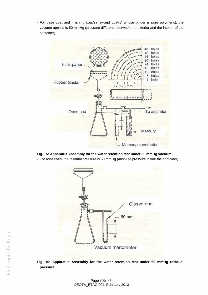
Page 100/143©EOTA_ETAG 004, February 2013
- For base coat and finishing coat(s) (except coat(s) whose binder is pure polymeric), thevacuum applied is 50 mmHg (pressure difference between the exterior and the interior of thecontainer)
Fig. 15: Apparatus Assembly for the water retention test under 50 mmHg vacuum- For adhesives, the residual pressure is 60 mmHg (absolute pressure inside the container)
Fig. 16: Apparatus Assembly for the water retention test under 60 mmHg residualpressure
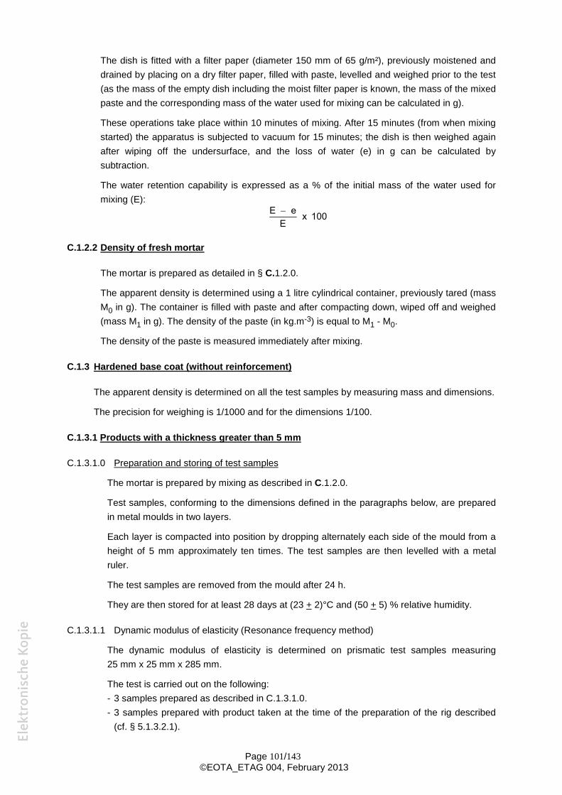
Page 101/143©EOTA_ETAG 004, February 2013
The dish is fitted with a filter paper (diameter 150 mm of 65 g/m²), previously moistened anddrained by placing on a dry filter paper, filled with paste, levelled and weighed prior to the test(as the mass of the empty dish including the moist filter paper is known, the mass of the mixedpaste and the corresponding mass of the water used for mixing can be calculated in g).
These operations take place within 10 minutes of mixing. After 15 minutes (from when mixingstarted) the apparatus is subjected to vacuum for 15 minutes; the dish is then weighed againafter wiping off the undersurface, and the loss of water (e) in g can be calculated bysubtraction.
The water retention capability is expressed as a % of the initial mass of the water used formixing (E):
E eE
x 100
C.1.2.2 Density of fresh mortar
The mortar is prepared as detailed in § C.1.2.0.
The apparent density is determined using a 1 litre cylindrical container, previously tared (massM0 in g). The container is filled with paste and after compacting down, wiped off and weighed(mass M1 in g). The density of the paste (in kg.m-3) is equal to M1 - M0.
The density of the paste is measured immediately after mixing.
C.1.3 Hardened base coat (without reinforcement)
The apparent density is determined on all the test samples by measuring mass and dimensions.
The precision for weighing is 1/1000 and for the dimensions 1/100.
C.1.3.1 Products with a thickness greater than 5 mm
C.1.3.1.0 Preparation and storing of test samples
The mortar is prepared by mixing as described in C.1.2.0.
Test samples, conforming to the dimensions defined in the paragraphs below, are preparedin metal moulds in two layers.
Each layer is compacted into position by dropping alternately each side of the mould from aheight of 5 mm approximately ten times. The test samples are then levelled with a metalruler.
The test samples are removed from the mould after 24 h.
They are then stored for at least 28 days at (23 + 2)°C and (50 + 5) % relative humidity.
C.1.3.1.1 Dynamic modulus of elasticity (Resonance frequency method)
The dynamic modulus of elasticity is determined on prismatic test samples measuring25 mm x 25 mm x 285 mm.
The test is carried out on the following:- 3 samples prepared as described in C.1.3.1.0.- 3 samples prepared with product taken at the time of the preparation of the rig described
(cf. § 5.1.3.2.1).
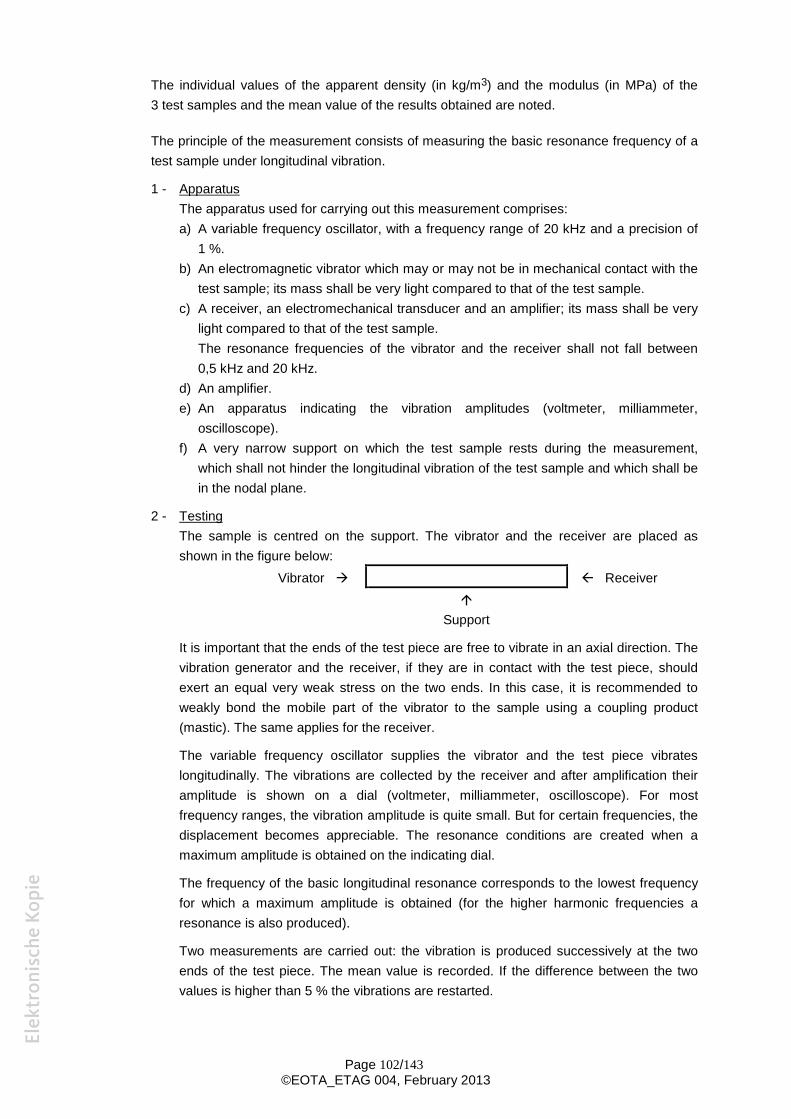
Page 102/143©EOTA_ETAG 004, February 2013
The individual values of the apparent density (in kg/m3) and the modulus (in MPa) of the3 test samples and the mean value of the results obtained are noted.
The principle of the measurement consists of measuring the basic resonance frequency of atest sample under longitudinal vibration.
1 - ApparatusThe apparatus used for carrying out this measurement comprises:a) A variable frequency oscillator, with a frequency range of 20 kHz and a precision of
1 %.b) An electromagnetic vibrator which may or may not be in mechanical contact with the
test sample; its mass shall be very light compared to that of the test sample.c) A receiver, an electromechanical transducer and an amplifier; its mass shall be very
light compared to that of the test sample.The resonance frequencies of the vibrator and the receiver shall not fall between0,5 kHz and 20 kHz.
d) An amplifier.e) An apparatus indicating the vibration amplitudes (voltmeter, milliammeter,
oscilloscope).f) A very narrow support on which the test sample rests during the measurement,
which shall not hinder the longitudinal vibration of the test sample and which shall bein the nodal plane.
2 - TestingThe sample is centred on the support. The vibrator and the receiver are placed asshown in the figure below:
Vibrator Receiver
Support
It is important that the ends of the test piece are free to vibrate in an axial direction. Thevibration generator and the receiver, if they are in contact with the test piece, shouldexert an equal very weak stress on the two ends. In this case, it is recommended toweakly bond the mobile part of the vibrator to the sample using a coupling product(mastic). The same applies for the receiver.
The variable frequency oscillator supplies the vibrator and the test piece vibrateslongitudinally. The vibrations are collected by the receiver and after amplification theiramplitude is shown on a dial (voltmeter, milliammeter, oscilloscope). For mostfrequency ranges, the vibration amplitude is quite small. But for certain frequencies, thedisplacement becomes appreciable. The resonance conditions are created when amaximum amplitude is obtained on the indicating dial.
The frequency of the basic longitudinal resonance corresponds to the lowest frequencyfor which a maximum amplitude is obtained (for the higher harmonic frequencies aresonance is also produced).
Two measurements are carried out: the vibration is produced successively at the twoends of the test piece. The mean value is recorded. If the difference between the twovalues is higher than 5 % the vibrations are restarted.
Page 103/143©EOTA_ETAG 004, February 2013
The measurements of the mass and dimensions of the test piece are needed tocalculate the modulus. The precision for weighing is 1/1000 and for the dimensions1/100.
Expressing the resultsAs the basic longitudinal resonance frequency, the mass and the dimensions of the testpiece are known the dynamic modulus of elasticity is determined using the followingformula:
Ed = 4L2 . F2 10-6
Ed = Longitudinal dynamic modulus of elasticity in Newtons per square millimetre.L = Length of test piece in metres.F = Longitudinal resonance frequency in Hertz.
= Mass per unit volume in kg/m3.
C.1.3.1.2 Shrinkage test
The measurement is carried out on three samples of base coat measuring20 mm x 40 mm x 160 mm prepared and stored as described in C.1.3.1.0, by insertingmeasuring spindles in the front end (10 mm x 40 mm) of the samples. Measurements arecarried out at regular intervals. The value after 28 days is recorded. In addition if there isdoubt in the curve associated with stabilisation, the test is continued and the value after 56days is recorded.
C.1.3.2 Products with a thickness up to 5 mm: static modulus of elasticity, tensile strength andelongation at break
The tests are performed on test samples measuring 3 mm x 50 mm x 300 mm.
Moulds for the samples are made using appropriately positioned 3 mm thick strips of extrudedpolystyrene adhered to expanded polystyrene boards.
After the base coat, without reinforcement has dried, test samples are cut from the polystyrenewith hot wire.
The test sample is subjected to a tensile test until it breaks using a suitable machine whichrecords the tensile stress and elongation. The distance between the jaws of the machine is200 mm. The sample is held between the jaws with the interposition of pads.
The tensioning speed is 2 mm/minute.
The tests are carried out on five samples stored for at least 28 days at (23 + 2)°C and(50 + 5)% RH and on five samples which have undergone the hygrothermal test (placed in thewindow of the rig).
C.2 Insulation product
C.2.1 Density measurement
In accordance with EN 1602.
Page 104/143©EOTA_ETAG 004, February 2013
C.2.2 Dimensional characteristics and appearance
C.2.2.1 Length and width
In accordance with EN 822.
C.2.2.2 Thickness
In accordance with EN 823.
C.2.2.3 Squareness
In accordance with EN 824.
C.2.2.4 Flatness
In accordance with EN 825.
C.2.2.5 Surface condition
This is visually assessed.
C.2.3 Compression test
In accordance with EN 826.
This test is not necessary for EPS insulation.
C.2.4 Dimensional stability tests
In accordance with:- EN 1603;- EN 1604 (conditionings specified in the relevant product standard).
C.3. Reinforcement
C.3.1 Mass per unit area
The mass per unit area is determined by measuring and weighing a one metre length of mesh.For reinforcement in roll form, the width of the sample should be the same as the roll width.
The result is expressed in g/m².
C.3.2 Ash content
This test applies to glass fibre mesh only.
The ash content is determined at (625 + 20)°C on three 100 mm square samples, cut parallelto the yarn and at least 100 mm apart from the side to constant mass.
The result is expressed as a percentage relative to the initial mass.
Page 105/143©EOTA_ETAG 004, February 2013
C.3.3 Mesh size and number of filaments
The mesh size is determined by measuring the distance between 21 yarns (e.g. 20 mesh) inwarp and in weft direction.
The mesh opening is calculated by subtracting the thickness of the yarn from the mesh size.
C.3.4 Elongation
The result of the test § 5.6.7.1 shall be stated in the ETA.
C.4 Mechanical fixing devices
C.4.1 Dimensions
The measurements shall be stated in the ETA.
C.4.2 Load characteristics if necessary (depending on the type of material)
The result shall be stated in the accompanying documents.
C.5 Foam adhesives
The identification tests relevant for foam adhesives are described in the EOTA TechnicalReport "Test methods for foam adhesives for ETICS".
A n n e x D :R E A C T I O N T O F I R E
D.1. General:
Principle
The determination of reaction to fire of the ETICS is based on testing of “the worst case” - the most critical configurationin sense of reaction to fire. According to the rules described further in the text, the classification obtained on the mostcritical ETICS configuration is valid for all configurations having better performance in sense of reaction to fire.
For the particular types of ETICS components the following principles apply:- the base coat and finishing coat with the highest amount of organic content (related to the mass in driedcondition as in end use application) or the highest PCS value (according to EN ISO 1716)1 shall be used forpreparing the specimen,- each decorative coat and key coat shall be tested unless it can be neglected according to the rules below. Ifthere are only differences in the amount of organic content but no difference in the organic component itself, thedecorative coat and the key coat with the highest organic content or the highest PCS value (according to EN ISO1716)1 of this organic component shall be tested,- the decorative coat and/or the key coat can be neglected as long as they comply with the following 2:
the thickness of the decorative coat is less than 200 μm and the content of organic components is of not more than 5 % (related to the mass in dried condition as inend use application)
- In addition, each coat selected for testing according to the rules above before shall have the lowest amount offlame retardants.
Product properties influencing the reaction to fire behaviour
- Type of insulation product (composition, thickness, density)- Type of base coat and finishing coats (composition, thickness, mass per unit area)- Type of key coats and decorative coats (composition, mass per unit area)- Type of reinforcement (composition, thickness, mass per unit area)- Type and nature of fixings- Type and nature of fire breaks (interruptions to the continuity of insulation or any cavity)3
- The organic content of the binder and of any organic additive; this can be checked by providing the formulation ofthe component, by performing suitable identification tests or by determining the glow loss or net calorific value
- Type and amount of flame retardant intended to maintain or improve the reaction to fire performance of theETICS or its components and consequently of building elements to which they are applied.
Although the rest of this annex applies the “worst case scenario” for deciding what to test, it is accepted that, where theETA applicant produces a range of ETICS having different overall classifications, he may group these together into anumber of different sub-groups (e.g. each sub-group corresponding to a different overall classification) with the ‘worstcase scenario’ being identified for each sub-group.
1 The ETA-applicant is responsible for the information on organic content per unit area. If the information is not available, the PCS value is testedto decide about the worst case.
2 This rule can be reconsidered when more experience and test result are available3 Fire breaks are important for the behaviour of the whole façade cladding system and cannot be assessed on the basis of SBI-testing. The
influence can only be observed during a large scale test. Therefore breaks are not included in the mounting and fixing rules for the SBI-test. AEuropean fire scenario for façades has not been laid down. An additional assessment according to national provisions (e.g. on the basis ofexamining design solutions or a large scale test) might be necessary to comply with Member State regulations, until the existing Europeanclassification system has been completed.
Page 107/143©EOTA_ETAG 004, February 2013
Components of an ETICS, where these require separate assessment (as opposed to being tested as part of the ETICSas a whole), which are classified A1 without testing according to Decision 96/603, as amended, do not need to be tested.
D.2. Testing according to EN ISO 1182
This test method is relevant for the classes A1 and A2.
Using this test method, only the ‘substantial components’ of the ETICS need to be tested. ‘Substantial components’ aredefined by thickness ( 1 mm) and/or mass per unit area ( 1 kg/m²).
In the following, the insulation product, the base coat and the finishing coat are identified as the most significant‘substantial components’, but the adhesive, the key coat, the decorative coat and any reinforcement may also be‘substantial components’.Parameters relevant for this test method are:
- Composition,- density.
D.2.1 Insulation product
For ETICS expected to be classified as A1 or A2, it is anticipated that only insulation products with reaction to fire classA1 or A2 will form the insulation layer. For testing the insulation product reference shall be made to the relevant productstandards and SH02 documents (e.g. “Fire testing and classification protocol for mineral wool products”) or other relevantdocuments.
D.2.2 Render coatingsD.2.2.1 Base coats and finishing coats
The reaction to fire behaviour of base coats and finishing coats not falling under EC Decision 96/603/EC (as amended)shall be tested according to the principle specified in § General.
The test result can be directly applied to all variants with the same base coat and finishing coat and with a lower amountof organic components. When the subject of the directly applied result contains a flame retardant, it shall be of the sametype and its content shall be at least that of the product tested.
Differences concerning the density shall be considered by testing the lowest and the highest density.
D.2.2.2 Key coats and decorative coats
The principles specified in clause D.1 “Principle” shall be applied.
D.2.3 Adhesive
The same rules as given in D.2.2 above shall be applied.
D.2.4 Reinforcement
Each type of reinforcement that fulfils the requirements of a ‘substantial component’ shall be tested according to EN ISO1182. Reinforcement that is randomly dispersed (e.g. fibres) in the render shall be tested as part of the render.
D.3. Testing according to EN ISO 1716
This test method is relevant for the classes A1 and A2.
This test method shall be performed to all components of the ETICS except for cases which are classified as A1 withouttesting.
Parameters relevant for this test method are: composition (when performing calculation of the PCSS-value, density ormass per unit area and thickness are relevant). Mechanical fixings and ancillary materials which are not continuous butdiscrete components of ETICS shall not to be considered for testing and for the calculation of the PCSS.
Page 108/143©EOTA_ETAG 004, February 2013
D.3.1. Insulation product
For testing the insulation product, reference shall be made to the relevant product standards and SH02 documents (e.g.“Fire testing and classification protocol for mineral wool products”) or other related documents.
It is not realistic to require that each insulation product of the same type is tested within the classification of an ETICS. Ifthe insulation products come from different manufacturers and/or are of different thickness, density and formulation fromthose used in the testing, these may be used subject to the requirements of class A1 and A2 still being fulfilled. It shall beproved by calculation (undertaken by an Approval Body or Notified Body) that the ETICS, together with the actualinsulation product used in end use application, still fulfils the requirements concerning the PCS-value of the wholeproduct. For example, it is sufficient to determine the PCS-value of the mineral wool and if this is lower than the originallytested product then it is acceptable to use the alternative mineral wool instead of that used in the original test.
Note: Information relating to alternative insulation products of the same type to that originally tested may be evaluated onthe basis of the supplier's evidence provided within the context of its CE marking.
D.3.2. Render coating
In general, when performing calculations of the unit area referred PCSS-value (related to the surface) the variant thatprovides the highest PCSS-value shall be considered.The test shall be performed in accordance with the principles specified in D.1 General applied to each component of therender coating.It is not necessary to test a finishing coat with different grain sizes if the organic content is the same as or lower than thatof the tested coat.
The test results can be directly applied to all variants with the same render coating but with a lower amount of organiccomponents. When the subject of the directly applied result contains a flame retardant, it shall be of the same type andits content shall be at least that of the product tested.
D.3.3 Adhesive
For the component adhesive of the ETICS, each product with a different formulation shall be tested for reaction to firebehaviour by selecting the variant with the highest amount of organic components. The test results can be directlyapplied to all variants with the same composition but lower amount of organic components. For the case where one ofthe render coatings is used as the adhesive, the rules according to D.3.2 shall be applied.
D.3.4. Reinforcement
Each type of reinforcement shall be tested according to EN ISO 1716. For reinforcement that is randomly dispersed (e.g.fibres) in the render then it shall be tested as part of the render.
D.4. Testing according to EN 13823 (SBI-test)
This test method is relevant for the classes A2, B, C and D (in some cases also for A14).
In this test procedure the complete ETICS shall be tested. The ETICS is fixed to a substrate representing that on whichthe ETICS is fixed in the end use application (reference is made to EN 13238). The fixing shall be made using either theadhesive used in the end use application or, in the case of purely mechanical fixing, by using the means of mechanicalfixing used in the end use application. When adhesives are used, the test result is valid also for mechanical fixings.When a purely mechanical fixing with plastic anchors is used the test result is valid also for metallic anchors.
The maximum testable thickness of the test specimen, including a standard substrate according to EN 13238, is 200mm. However, in practice, for many ETICS, the total overall thickness may be greater than 200 mm. In such cases, usinga standard substrate, the thickness of the insulation product shall be reduced to provide for the maximum specimenthickness of 200 mm. Results obtained on an ETICS at 200 mm thickness are accepted for greater thicknesses.
4 In cases according to EC Decision 2000/147/EC, Table 1, Footnote 2a; A1 case mentioned in EN 13501-1 does not apply to ETICS
Page 109/143©EOTA_ETAG 004, February 2013
The test specimen consists of a corner construction which shall be representative of the construction in practice. Alledges are covered with the rendering system excluding the bottom edge and the top of the specimen. The floor of thetest trolley beneath the test specimen can be covered by an aluminium foil. See figure D.1.
It is recommended to either prepare the specimens at the lab and then put it onto the trolley (with the foil on), or the ETA-applicant builds the wall at the factory and carries it to the lab where it is put onto the trolley. After preparation of the testspecimens they shall be conditioned according to EN 13238.
Parameters which are relevant:- amount of adhesive- type, thickness and density of insulation product- type, binder and thickness of each coat of render coating- amount of organic content of each coat of render coating- amount of flame retardant of each coat of render coating- type of reinforcement
In principle, it is desirable to find the test specimen configuration that gives the worst case concerning the reaction to firetest results. In the test procedure according to EN 13823, values for the rate of heat release, total heat release, lateralflame spread, rate of smoke release, total smoke release and burning droplets are determined. Due to the possibleeffects of the insulation product, the following proposals are divided by considering separately the testing of ETICS withclass A1 and A2 insulation products and the testing of ETICS with class B, C, D and E insulation products.
D.4.1 Insulation product
For the testing of ETICS with insulation products with reaction to fire class A1 or A2 the insulation product with thehighest thickness, the highest density (with a tolerance of ±10 %) and the highest organic content (related to the mass indried condition) has to be used for preparing the test specimen. The reaction to fire classes A1 or A2 of the insulationproduct shall be proven separately.5
For the testing of ETICS with insulation products with reaction to fire class B, C, D or E, each type of insulation product(PS, PUR etc. plus taking into account the reaction to fire class of the insulation product) shall be tested within thesystem. For each type of insulation product the insulation product with the highest thickness and the highest density (witha tolerance of 10 %) shall be used for preparing the test specimen. The reaction to fire class B, C, D or E of the insulationproduct shall be proven separately.5
For testing ETICS which are mounted onto the substrate by using an adhesive (only bonded or mechanically fixed andbonded) specimens shall be tested
- with the highest thickness of the insulation product in cases where the adhesive has an organic content of equalto or less than 15 % (related to the mass in dried condition and in end use application) and- with the highest and the lowest thickness of the insulation product in cases where the adhesive has an organiccontent of more than 15 % (related to the mass in dried condition and in end use application).
D.4.2 Render coatings
By testing one specific render coating representing a range of different coats, the following rules shall be applied todiscriminate the composition, which is able to represent a range of coats:
- The base coat, the key coat, the finishing coat and the decorative coat to be used for preparing the specimen,taking account of the permissible combination(s) allowed by the manufacturer, shall be determined in accordancewith the principles specified in D.1. General.- For a base coat and a finishing coat having an organic content less than or equal to 5% (related to the mass indried condition as used in the end use application), only the lowest thickness needs to be used for preparing thetest specimen.
5 In some Member States requirements might exist to demonstrate the behaviour of products with respect to continuous glowing combustion inthe case of fire. The mandates for the product standards, therefore, are currently under revision. Additional national assessment e.g. on thebasis of national procedures to demonstrate this behaviour might be required until a European harmonised procedure is available.
Page 110/143©EOTA_ETAG 004, February 2013
- For a base coat or a finishing coat having an organic content higher than 5%, both the lowest and the highestthickness of the layer of the base coat and finishing coat shall be used for preparing the test specimens.
Regardless of the organic content, only the highest thickness of a base coat and a finishing coat shall be tested oninsulation material with class A1 or A2-s1,d0.When the only difference in coatings is thickness and it is 0,5 mm or less, the coatings may be considered to be thesame.
D.4.3 Adhesive
The influence of the type of adhesive having an organic content of equal to or less than 15% (related to the mass in drycondition) is assumed to be negligible. Only the amount of organic content is considered important. Therefore, anadhesive with the highest amount of organic content should be used for preparing the test specimens applied at themaximum thickness.The influence of adhesives having an organic content of more than 15 % can not be assumed to be negligible. Therefore,each type of adhesive with a different composition shall be tested by selecting the variant with the highest organiccontent.
D.4.4 Reinforcement
The specimens shall be prepared with the reinforcement that is intended to be used in end use application. If differentreinforcements are intended to be used, the reinforcement with the highest PCSS-value per unit area shall be used forpreparing the SBI specimen. At the long wing of the SBI specimens a vertical joint of the reinforcement shall be includedat a distance of 200 mm away from the inner corner of the specimens by 100 mm overlapping of the two layers of thereinforcement (that means the joint begins at a distance of 150 mm and ends at a distance of 250 mm away from theinner corner). The test results from a system with an overlap of the reinforcement of 10 cm are valid for all joints with anoverlapping of 10 cm or more.
D.4.5 Application of test results
The test result is valid for:- insulation products:
of the same type, with lower density with lower thickness or between those evaluated in the tests, provided that the worst result of the twothicknesses tested is used for intermediate thicknesses, with equal or less organic content,
- base coats and finishing coats: with equal or less organic content, with equal or greater content of the same type of flame retardants, with equal or greater thickness if the organic content is equal to or less than 5 %, base coat and finishing coat having more than 5% organic content:
o with thickness between those evaluated, provided that the worst result of the two thicknesses testedis used for intermediate thicknesses
- key coats: with equal or less organic content, with equal or greater content of the same type of flame retardants,
- decorative coats: with equal or less organic content per unit area, with equal or greater content of the same type of flame retardants,
- adhesives: with equal or less organic content and equal or less thickness if the organic content is equal to or less than15 %,
Page 111/143©EOTA_ETAG 004, February 2013
of the same type, with equal or less organic content and equal or less thickness if the organic content isgreater than 15 %,
- reinforcements: with an equal or lower PCSS-value per unit area.
D.5. Testing according to EN ISO 11925-2
This test method is relevant for the classes B, C, D and E.
In this test procedure, the ETICS is tested without using a substrate. The maximum thickness of the test specimen is 60mm. In cases where the thickness of the ETICS is larger than 60 mm, the insulation product may be reduced for thepurposes of testing. The results from the testing of specimens at 60 mm are applicable to greater thicknesses.
Parameters which are relevant:- type and amount of adhesive,- type, thickness and density of insulation product- type, binder and thickness of each coat of render coating- amount of organic content of each coat of render coating- amount of flame retardant of each coat of render coating- type of reinforcement
The specimens are prepared in such a way that the edges are not covered with the rendering system (cut edges). Thetests are performed with surface flaming of the front side and possibly edge flaming of the test specimen turned by 90°according to the rules of standard EN ISO 11925-2.
D.5.1 Insulation product
An insulation product, representative in its characterisation (type, reaction to fire classification and density) for the enduse application shall be used. The ETICS shall be evaluated incorporating the insulation product at the highest possiblethickness and the highest and the lowest possible densities.
For ETICS with insulation products made of polystyrene or polyurethane (PUR) classified class E, the test results arevalid only for the insulation products as used in the test. ETA Applicants have the possibility of using insulation productsfrom different manufacturers when the following additional tests are performed and conditions are fulfilled or themanufacturer provides the necessary evidence. For insulation products made of polystyrene or PUR, it shall be provenseparately that the product fulfils the requirements for reaction to fire class E under the following conditions. Polystyreneinsulation has to be tested with the highest density and at a thickness of 10 mm for expanded polystyrene foam and atthe minimum thickness produced for extruded polystyrene. The test result is valid for lower densities and higherthicknesses. PUR insulation shall be tested at the density intended for the end use and at the highest thickness. The testresult is valid for PUR insulation with the same density and for lower thicknesses.
D.5.2 Render coatings
For testing one specific rendering system representing a range of different coats, the rules as mentioned in D.4.2 apply.
D.5.3 Adhesive
For adhesives (mortars) having an organic content of equal to or lower than 15 % (related to the mass in dried condition)it can be assumed that they fulfil the requirements of the class B without testing according to EN ISO 11925-2. Therefore,no need exists to take into account such adhesives for preparing and testing specimens of ETICS according to thisstandard.For adhesives having an organic content of more than 15 % (related to the mass in dried condition) it is necessary tocarry out a complete set of six additional tests on specimens turned at 90 degrees on their vertical axis with edgeexposure of the adhesive layer. The specimens consist of the substrate, the adhesive and the insulation product. Thefollowing rules shall be applied for preparing the specimens.
- Each type of adhesive with a different composition shall be used by selecting the variant with the highest amountof organic content and with the highest thickness,

Page 112/143©EOTA_ETAG 004, February 2013
- The insulation product shall be used with the lowest thickness applied for the approval- The substrate shall be the same as the one used for SBI testing of the ETICS as a whole.
D.5.4 Reinforcement
The specimen shall be prepared with the reinforcement intended to be used in end use application. If differentreinforcements are intended to be used, the reinforcement with the highest PCSS-value per unit area has to be tested.
D.5.5 Application of test results
The test result covers end use application arrangements with the same type of insulation product (excluding insulationmade of polystyrene or PUR) as used in the tests with thicknesses and densities as described in D.5.1 and equal orlower organic content.
The test results from tests with insulation products made of polystyrene or PUR classified class E are valid for ETICSwith insulation products as used in the test or for ETICS with any polystyrene and PUR insulation products classifiedclass E when the test evidence according to D.5.1 was provided.
For the direct application of test results regarding base coat, key coat, finishing coat, decorative coat, reinforcement andadhesive the same rules shall apply as given in clause D.4.5.
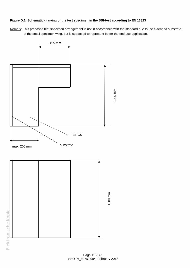
Page 113/143©EOTA_ETAG 004, February 2013
Figure D.1: Schematic drawing of the test specimen in the SBI-test according to EN 13823
Remark: This proposed test specimen arrangement is not in accordance with the standard due to the extended substrateof the small specimen wing, but is supposed to represent better the end use application.
1000
mm
mm
495 mm
substrate
ETICS
1500
mm
max. 200 mm
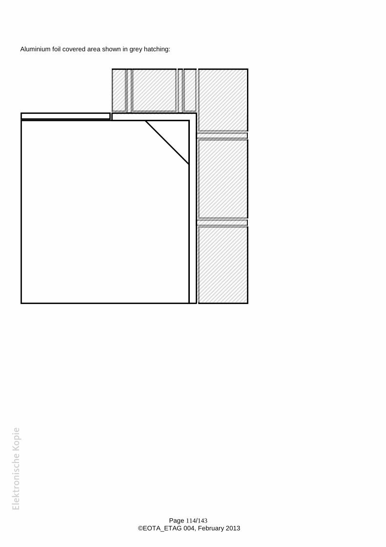
Page 114/143©EOTA_ETAG 004, February 2013
Aluminium foil covered area shown in grey hatching:
Page 115/143©EOTA_ETAG 004, February 2013
A n n e x E :E T A m o d e l
...………….(Coordinates of Approval Body)
Authorizedand notified according
to Article 10 of the CouncilDirective of 21 December 1988on the approximation of laws,regulations and administrativeprovisions of Member States
relating to constructionproducts
(89/106/EEC)
……..(Logo of Approval Body)
[Membre de l’EOTA]Member of EOTA
European Technical Approval ETA-../....(English translation prepared by ………… - Original version in …………….. language)
Trade name:Nom commercial :
ETICS Name A / ETICS Name B
Company XHolder of approval:Titulaire :
Generic type and use ofconstruction product:
External Thermal Insulation Composite Systems withrendering on polystyrene for the use as external insulationto the walls of buildings.
Type générique et utilisation prévue duproduit de construction :
Système d’isolation thermique extérieure par enduit sur polystyrèneexpansé destiné à l’isolation thermique extérieure des murs debâtiments.
Validity from / to:Validité du :
au :
Manufacturing plant:Usine de fabrication :
Company X
This European Technical Approvalcontains:Le présent Agrément Technique Européencontient :
….. pages including 3 annexes….. pages incluant 3 annexes
Organisation pour l’Agrément Technique Européen
European Organisation for Technical Approvals
Page XXX of ETA-xx/xxxx, issued on dd.mm.yyyy, English translation by ……………Page XXX of ETA-xx/xxxx, issued on dd.mm.yyyy, validity extended on dd.mm.yyyy, English translation by ……
Page 117/143©EOTA_ETAG 004, February 2013
I LEGAL BASES AND GENERAL CONDITIONS
1 - This European Technical Approval is issued by the “Name of the Approval Body” in accordance with:
- Council Directive 89/106/EEC of 21 December 1988 on the approximation of laws, regulations andadministrative provisions of Member States relating to construction products6, modified by theCouncil Directive 93/68/EEC7 and Regulation (EC) no. 1882/2003 of the European Parliament andof the Council3;
- (indicate respective national law4 transposing the CPD; only if the national law of the Member Stateof the issuing Approval Body so requires);
- Common Procedural Rules for Requesting, Preparing and the Granting of European TechnicalApprovals set out in the Annex to Commission Decision 94/23/EC5;
- Guideline for European Technical Approval of “External Thermal Insulation Composite Systemswith rendering “ETAG no. 004, edition 2012.
2 - The “Name of the Approval Body” is authorised to check whether the provisions of this EuropeanTechnical Approval are met. Checking may take place in the manufacturing plant. Nevertheless, theresponsibility for the conformity of the products to the European Technical Approval and for theirfitness for the intended use remains with the holder of the European Technical Approval.
3 - This European Technical Approval is not to be transferred to manufacturers or agents of manufacturerother than those indicated on page 1; or manufacturing plants other than those laid down in thecontext of this European Technical Approval.
4 - This European Technical Approval may be withdrawn by the “Name of the Approval Body”, inparticular pursuant to information by the Commission according to Article 5(1) of Council Directive89/106/EEC.
5 - Reproduction of this European Technical Approval including transmission by electronic means shall bein full. However, partial reproduction can be made with the written consent of the «Name of theApproval Body». In this case, partial reproduction has to be designated as such. Texts and drawingsof advertising brochures shall not contradict or misuse the European Technical Approval.
6 - The European Technical Approval is issued by the Approval Body in its official language. This versioncorresponds fully to the version circulated within EOTA. Translations into other languages have to bedesignated as such.
6 Official Journal of the European Communities no. L 40, 11.2.1989, p. 127 Official Journal of the European Communities no. L 220, 30.8.1993, p. 13 Official Journal of the European Union no. L 284, 31.10.2003, p. 1.4 National reference.5 Official Journal of the European Communities no. L 17, 20.1.1994, p. 34.
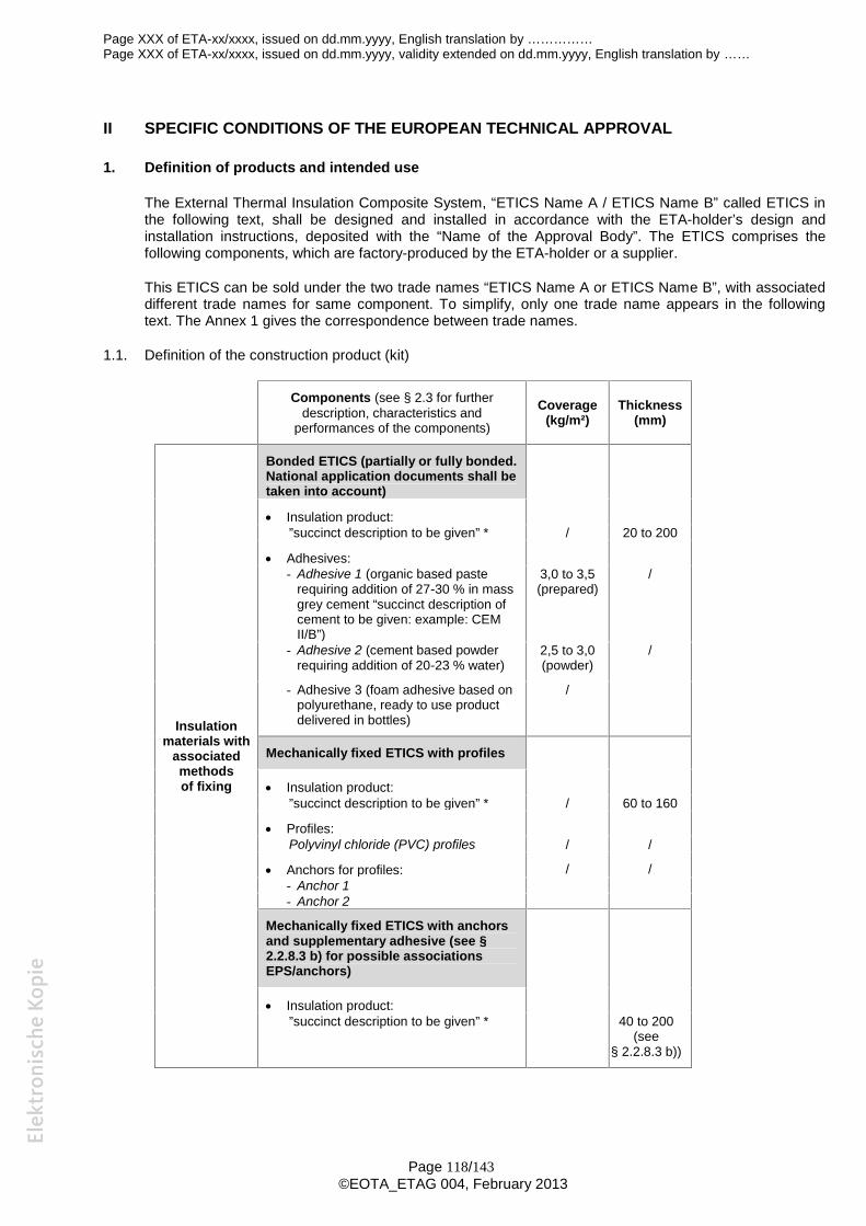
Page XXX of ETA-xx/xxxx, issued on dd.mm.yyyy, English translation by ……………Page XXX of ETA-xx/xxxx, issued on dd.mm.yyyy, validity extended on dd.mm.yyyy, English translation by ……
Page 118/143©EOTA_ETAG 004, February 2013
II SPECIFIC CONDITIONS OF THE EUROPEAN TECHNICAL APPROVAL
1. Definition of products and intended use
The External Thermal Insulation Composite System, “ETICS Name A / ETICS Name B” called ETICS inthe following text, shall be designed and installed in accordance with the ETA-holder’s design andinstallation instructions, deposited with the “Name of the Approval Body”. The ETICS comprises thefollowing components, which are factory-produced by the ETA-holder or a supplier.
This ETICS can be sold under the two trade names “ETICS Name A or ETICS Name B”, with associateddifferent trade names for same component. To simplify, only one trade name appears in the followingtext. The Annex 1 gives the correspondence between trade names.
1.1. Definition of the construction product (kit)
Components (see § 2.3 for furtherdescription, characteristics and
performances of the components)
Coverage(kg/m²)
Thickness(mm)
Insulationmaterials with
associatedmethodsof fixing
Bonded ETICS (partially or fully bonded.National application documents shall betaken into account)
Insulation product:”succinct description to be given” * / 20 to 200
Adhesives:- Adhesive 1 (organic based paste
requiring addition of 27-30 % in massgrey cement “succinct description ofcement to be given: example: CEMII/B”)
3,0 to 3,5(prepared)
/
- Adhesive 2 (cement based powderrequiring addition of 20-23 % water)
2,5 to 3,0(powder)
/
- Adhesive 3 (foam adhesive based onpolyurethane, ready to use productdelivered in bottles)
/
Mechanically fixed ETICS with profiles
Insulation product:”succinct description to be given” * / 60 to 160
Profiles:Polyvinyl chloride (PVC) profiles / /
Anchors for profiles: / /- Anchor 1- Anchor 2
Mechanically fixed ETICS with anchorsand supplementary adhesive (see §2.2.8.3 b) for possible associationsEPS/anchors)
Insulation product:”succinct description to be given” * 40 to 200
(see§ 2.2.8.3 b))
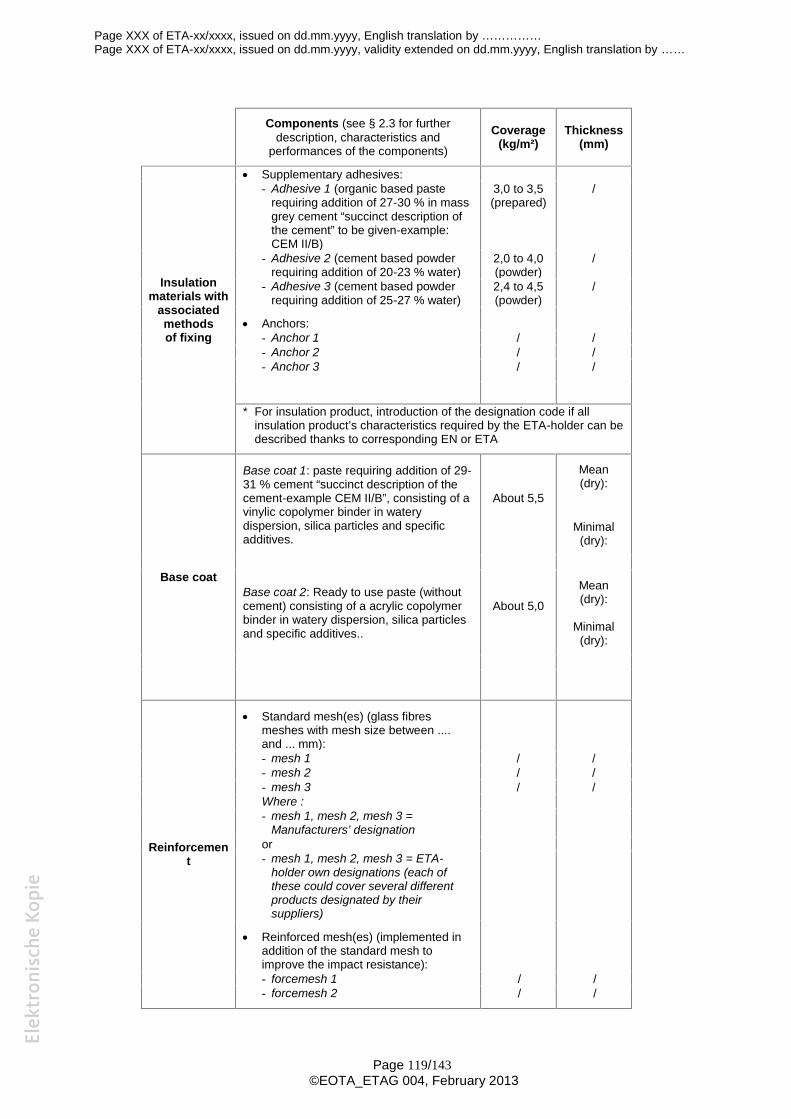
Page XXX of ETA-xx/xxxx, issued on dd.mm.yyyy, English translation by ……………Page XXX of ETA-xx/xxxx, issued on dd.mm.yyyy, validity extended on dd.mm.yyyy, English translation by ……
Page 119/143©EOTA_ETAG 004, February 2013
Components (see § 2.3 for furtherdescription, characteristics and
performances of the components)
Coverage(kg/m²)
Thickness(mm)
Insulationmaterials with
associatedmethodsof fixing
Supplementary adhesives:- Adhesive 1 (organic based paste
requiring addition of 27-30 % in massgrey cement “succinct description ofthe cement” to be given-example:CEM II/B)
3,0 to 3,5(prepared)
/
- Adhesive 2 (cement based powderrequiring addition of 20-23 % water)
2,0 to 4,0(powder)
/
- Adhesive 3 (cement based powderrequiring addition of 25-27 % water)
2,4 to 4,5(powder)
/
Anchors:- Anchor 1 / /- Anchor 2 / /- Anchor 3 / /
* For insulation product, introduction of the designation code if allinsulation product’s characteristics required by the ETA-holder can bedescribed thanks to corresponding EN or ETA
Base coat
Base coat 1: paste requiring addition of 29-31 % cement “succinct description of thecement-example CEM II/B”, consisting of avinylic copolymer binder in waterydispersion, silica particles and specificadditives.
About 5,5
Mean(dry):
Minimal(dry):
Base coat 2: Ready to use paste (withoutcement) consisting of a acrylic copolymerbinder in watery dispersion, silica particlesand specific additives..
About 5,0
Mean(dry):
Minimal(dry):
Reinforcement
Standard mesh(es) (glass fibresmeshes with mesh size between ....and ... mm):- mesh 1 / /- mesh 2 / /- mesh 3 / /Where :- mesh 1, mesh 2, mesh 3 =
Manufacturers’ designationor- mesh 1, mesh 2, mesh 3 = ETA-
holder own designations (each ofthese could cover several differentproducts designated by theirsuppliers)
Reinforced mesh(es) (implemented inaddition of the standard mesh toimprove the impact resistance):- forcemesh 1 / /- forcemesh 2 / /
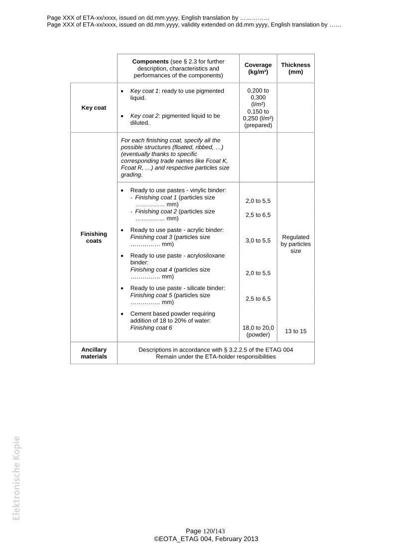
Page XXX of ETA-xx/xxxx, issued on dd.mm.yyyy, English translation by ……………Page XXX of ETA-xx/xxxx, issued on dd.mm.yyyy, validity extended on dd.mm.yyyy, English translation by ……
Page 120/143©EOTA_ETAG 004, February 2013
Components (see § 2.3 for furtherdescription, characteristics and
performances of the components)
Coverage(kg/m²)
Thickness(mm)
Key coat
Key coat 1: ready to use pigmentedliquid.
0,200 to0,300(l/m²)
Key coat 2: pigmented liquid to bediluted.
0,150 to0,250 (l/m²)(prepared)
Finishingcoats
For each finishing coat, specify all thepossible structures (floated, ribbed, …)(eventually thanks to specificcorresponding trade names like Fcoat K,Fcoat R, …) and respective particles sizegrading.
Ready to use pastes - vinylic binder:
Regulatedby particles
size
- Finishing coat 1 (particles size…………… mm) 2,0 to 5,5
- Finishing coat 2 (particles size…………… mm) 2,5 to 6,5
Ready to use paste - acrylic binder:Finishing coat 3 (particles size…………… mm) 3,0 to 5,5
Ready to use paste - acrylosiloxanebinder:Finishing coat 4 (particles size…………… mm) 2,0 to 5,5
Ready to use paste - silicate binder:Finishing coat 5 (particles size…………… mm) 2,5 to 6,5
Cement based powder requiringaddition of 18 to 20% of water:Finishing coat 6 18,0 to 20,0
(powder) 13 to 15
Ancillarymaterials
Descriptions in accordance with § 3.2.2.5 of the ETAG 004Remain under the ETA-holder responsibilities
Page XXX of ETA-xx/xxxx, issued on dd.mm.yyyy, English translation by ……………Page XXX of ETA-xx/xxxx, issued on dd.mm.yyyy, validity extended on dd.mm.yyyy, English translation by ……
Page 121/143©EOTA_ETAG 004, February 2013
1.2. Intended use
This ETICS is intended for use as external insulation of buildings’ walls. The walls are made of masonry(bricks, blocks, stones …) or concrete (cast on site or as prefabricated panels) with a reaction to fireclassification A1 to A2-s2,d0 according to EN 13501-1 or A1 according to the EC decision 96/603/EC asamended. The ETICS is designed to give the wall to which it is applied satisfactory thermal insulation.
The ETICS shall be designed and installed in accordance with ETA holder’s installation instructions andthis ETA. The kit consists of components defined by the ETA holder and manufactured either by the ETAholder or his supplier(s).
The ETICS is made of non load-bearing construction components. It does not contribute directly to thestability of the wall on which it is installed, but it can contribute to durability by providing enhancedprotection from the effect of weathering. The minimum thermal resistance of the ETICS shall be higherthan 1,0 m2K/W
The ETICS can be used on new or existing (retrofit) vertical walls. It can also be used on horizontal orinclined surfaces which are not exposed to precipitation.
The ETICS is not intended to ensure the airtightness of the building structure.
Design and installation of the ETICS should take into account principles laid down in the chapter 7 ofETAG 004 and shall be done in accordance with national instructions.
This ETA covers application of bonded ETICS where the concrete for testing of bond strength isrepresentative for masonry or concrete. For bonded applications onto other substrates (e.g. organicpaints or ceramic tiles), testing on the job site is necessary. (to be deleted when the ETA does not coverbonded system)
The provisions made in this European Technical Approval (ETA) are based on an assumed intendedworking life of at least 25 years, provided that the conditions laid down in sections 4.2, 5.1 and 5.2 for thepackaging, transport, storage and installation as well as appropriate use, maintenance and repair aremet. The indications given as to the working life cannot be interpreted as a guarantee given by themanufacturer or the Approval Body, but should only be regarded as a means for choosing the appropriateproducts in relation to the expected economically reasonable working life of the works.
2. Characteristics of products and methods of verification
2.1. General
The identification tests and the assessment of the fitness for use of this ETICS according to the EssentialRequirements were carried out in compliance with the “ETA Guidance no. 004” concerning ExternalThermal Insulation Composite Systems with rendering - edition XXX 20XX (called ETAG no. 004 in thisETA)
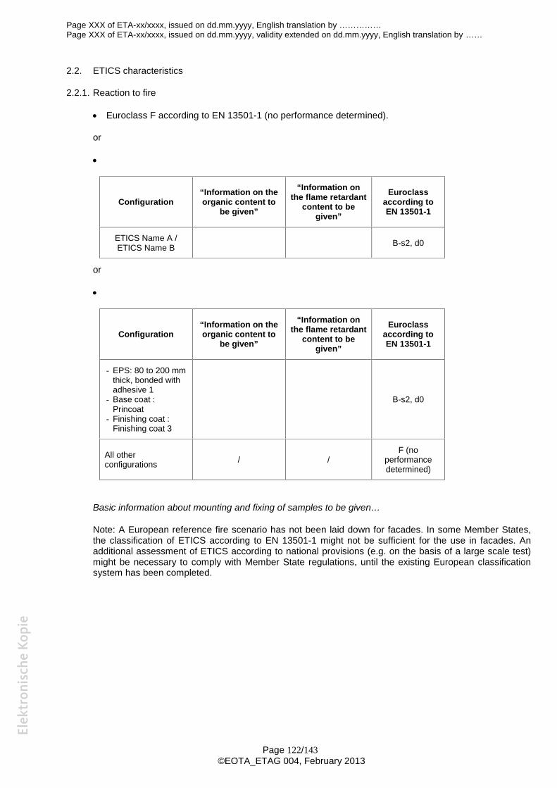
Page XXX of ETA-xx/xxxx, issued on dd.mm.yyyy, English translation by ……………Page XXX of ETA-xx/xxxx, issued on dd.mm.yyyy, validity extended on dd.mm.yyyy, English translation by ……
Page 122/143©EOTA_ETAG 004, February 2013
2.2. ETICS characteristics
2.2.1. Reaction to fire
Euroclass F according to EN 13501-1 (no performance determined).
or
Configuration“Information on theorganic content to
be given”
“Information onthe flame retardant
content to begiven”
Euroclassaccording toEN 13501-1
ETICS Name A /ETICS Name B B-s2, d0
or
Configuration“Information on theorganic content to
be given”
“Information onthe flame retardant
content to begiven”
Euroclassaccording toEN 13501-1
- EPS: 80 to 200 mmthick, bonded withadhesive 1
- Base coat :Princoat
- Finishing coat :Finishing coat 3
B-s2, d0
All otherconfigurations / /
F (noperformancedetermined)
Basic information about mounting and fixing of samples to be given…
Note: A European reference fire scenario has not been laid down for facades. In some Member States,the classification of ETICS according to EN 13501-1 might not be sufficient for the use in facades. Anadditional assessment of ETICS according to national provisions (e.g. on the basis of a large scale test)might be necessary to comply with Member State regulations, until the existing European classificationsystem has been completed.
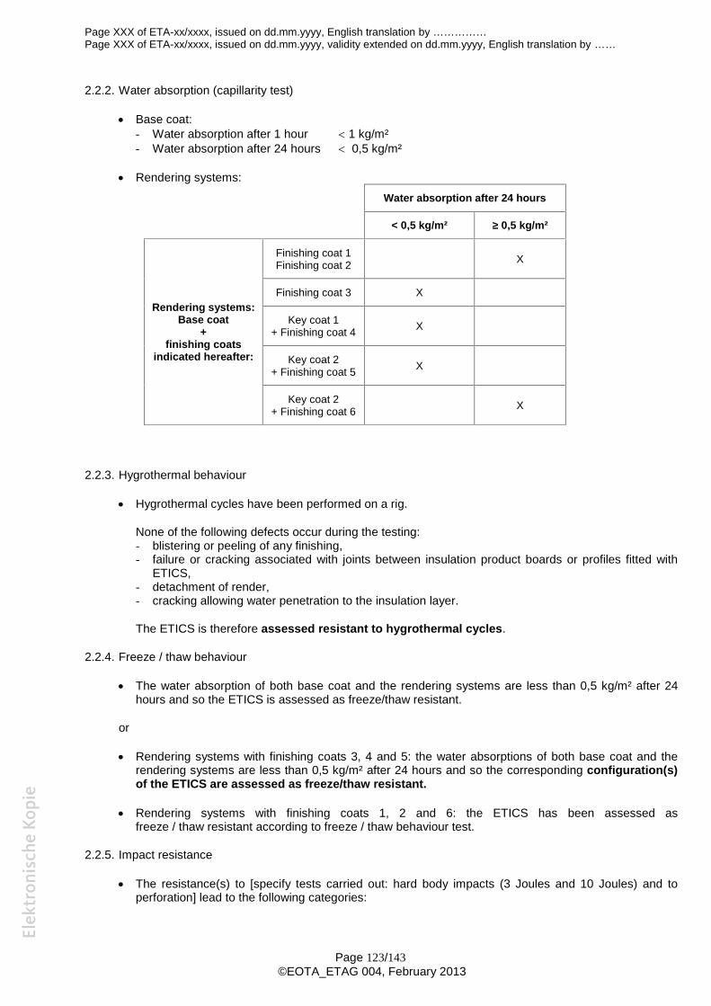
Page XXX of ETA-xx/xxxx, issued on dd.mm.yyyy, English translation by ……………Page XXX of ETA-xx/xxxx, issued on dd.mm.yyyy, validity extended on dd.mm.yyyy, English translation by ……
Page 123/143©EOTA_ETAG 004, February 2013
2.2.2. Water absorption (capillarity test)
Base coat:- Water absorption after 1 hour 1 kg/m²- Water absorption after 24 hours 0,5 kg/m²
Rendering systems:Water absorption after 24 hours
< 0,5 kg/m² ≥ 0,5 kg/m²
Rendering systems:Base coat
+finishing coats
indicated hereafter:
Finishing coat 1Finishing coat 2 X
Finishing coat 3 X
Key coat 1+ Finishing coat 4 X
Key coat 2+ Finishing coat 5 X
Key coat 2+ Finishing coat 6 X
2.2.3. Hygrothermal behaviour
Hygrothermal cycles have been performed on a rig.
None of the following defects occur during the testing:- blistering or peeling of any finishing,- failure or cracking associated with joints between insulation product boards or profiles fitted with
ETICS,- detachment of render,- cracking allowing water penetration to the insulation layer.
The ETICS is therefore assessed resistant to hygrothermal cycles.
2.2.4. Freeze / thaw behaviour
The water absorption of both base coat and the rendering systems are less than 0,5 kg/m² after 24hours and so the ETICS is assessed as freeze/thaw resistant.
or
Rendering systems with finishing coats 3, 4 and 5: the water absorptions of both base coat and therendering systems are less than 0,5 kg/m² after 24 hours and so the corresponding configuration(s)of the ETICS are assessed as freeze/thaw resistant.
Rendering systems with finishing coats 1, 2 and 6: the ETICS has been assessed asfreeze / thaw resistant according to freeze / thaw behaviour test.
2.2.5. Impact resistance
The resistance(s) to [specify tests carried out: hard body impacts (3 Joules and 10 Joules) and toperforation] lead to the following categories:
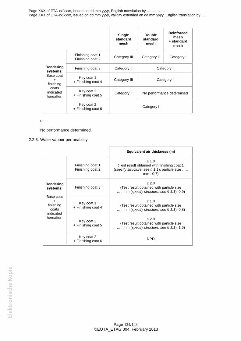
Page XXX of ETA-xx/xxxx, issued on dd.mm.yyyy, English translation by ……………Page XXX of ETA-xx/xxxx, issued on dd.mm.yyyy, validity extended on dd.mm.yyyy, English translation by ……
Page 124/143©EOTA_ETAG 004, February 2013
Singlestandard
mesh
Doublestandard
mesh
Reinforcedmesh
+ standardmesh
Renderingsystems:Base coat
+finishing
coatsindicatedhereafter:
Finishing coat 1Finishing coat 2 Category III Category II Category I
Finishing coat 3 Category II Category I
Key coat 1+ Finishing coat 4 Category III Category I
Key coat 2+ Finishing coat 5 Category II No performance determined
Key coat 2+ Finishing coat 6 Category I
or
No performance determined.
2.2.6. Water vapour permeability
Equivalent air thickness (m)
Renderingsystems:
Base coat+
finishingcoats
indicatedhereafter:
Finishing coat 1Finishing coat 2
1.0(Test result obtained with finishing coat 1
(specify structure: see § 1.1), particle size …..mm : 0,7)
Finishing coat 3 2.0
(Test result obtained with particle size….. mm (specify structure: see § 1.1): 0,9)
Key coat 1+ Finishing coat 4
1.0(Test result obtained with particle size
….. mm (specify structure: see § 1.1): 0,8)
Key coat 2+ Finishing coat 5
2.0(Test result obtained with particle size
….. mm (specify structure: see § 1.1): 1,6)
Key coat 2+ Finishing coat 6 NPD
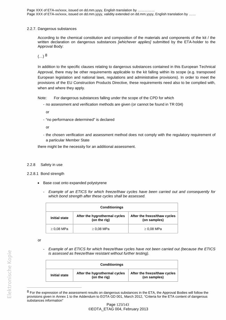
Page XXX of ETA-xx/xxxx, issued on dd.mm.yyyy, English translation by ……………Page XXX of ETA-xx/xxxx, issued on dd.mm.yyyy, validity extended on dd.mm.yyyy, English translation by ……
Page 125/143©EOTA_ETAG 004, February 2013
2.2.7. Dangerous substances
According to the chemical constitution and composition of the materials and components of the kit / thewritten declaration on dangerous substances [whichever applies] submitted by the ETA-holder to theApproval Body:
(…) 8
In addition to the specific clauses relating to dangerous substances contained in this European TechnicalApproval, there may be other requirements applicable to the kit falling within its scope (e.g. transposedEuropean legislation and national laws, regulations and administrative provisions). In order to meet theprovisions of the EU Construction Products Directive, these requirements need also to be complied with,when and where they apply.
Note: For dangerous substances falling under the scope of the CPD for which- no assessment and verification methods are given (or cannot be found in TR 034)
or
- “no performance determined” is declared
or
- the chosen verification and assessment method does not comply with the regulatory requirement ofa particular Member State
there might be the necessity for an additional assessment.
2.2.8 Safety in use
2.2.8.1 Bond strength
Base coat onto expanded polystyrene
- Example of an ETICS for which freeze/thaw cycles have been carried out and consequently forwhich bond strength after these cycles shall be assessed.
Conditionings
Initial state After the hygrothermal cycles(on the rig)
After the freeze/thaw cycles(on samples)
0,08 MPa 0,08 MPa 0,08 MPa
or
- Example of an ETICS for which freeze/thaw cycles have not been carried out (because the ETICSis assessed as freeze/thaw resistant without further testing).
Conditionings
Initial state After the hygrothermal cycles(on the rig)
After the freeze/thaw cycles(on samples)
8 For the expression of the assessment results on dangerous substances in the ETA, the Approval Bodies will follow theprovisions given in Annex 1 to the Addendum to EOTA GD 001, March 2012, “Criteria for the ETA content of dangeroussubstances information”
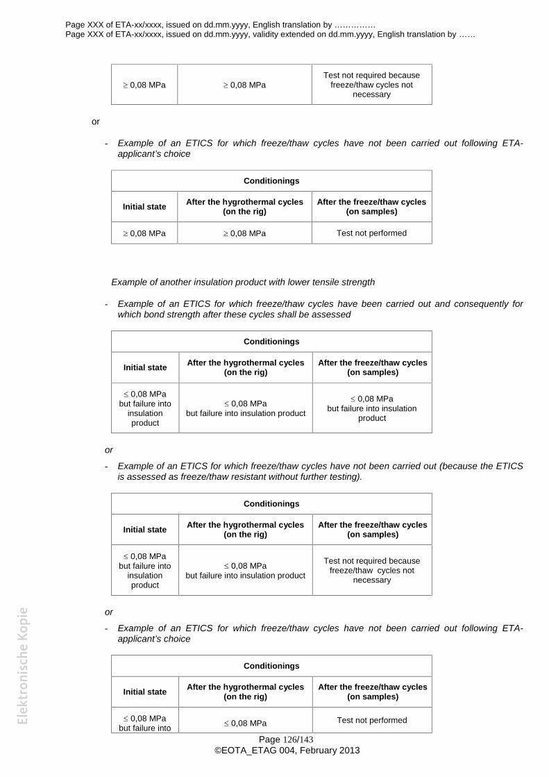
Page XXX of ETA-xx/xxxx, issued on dd.mm.yyyy, English translation by ……………Page XXX of ETA-xx/xxxx, issued on dd.mm.yyyy, validity extended on dd.mm.yyyy, English translation by ……
Page 126/143©EOTA_ETAG 004, February 2013
0,08 MPa 0,08 MPaTest not required because
freeze/thaw cycles notnecessary
or
- Example of an ETICS for which freeze/thaw cycles have not been carried out following ETA-applicant’s choice
Conditionings
Initial state After the hygrothermal cycles(on the rig)
After the freeze/thaw cycles(on samples)
0,08 MPa 0,08 MPa Test not performed
Example of another insulation product with lower tensile strength
- Example of an ETICS for which freeze/thaw cycles have been carried out and consequently forwhich bond strength after these cycles shall be assessed
Conditionings
Initial state After the hygrothermal cycles(on the rig)
After the freeze/thaw cycles(on samples)
0,08 MPabut failure into
insulationproduct
0,08 MPabut failure into insulation product
0,08 MPabut failure into insulation
product
or
- Example of an ETICS for which freeze/thaw cycles have not been carried out (because the ETICSis assessed as freeze/thaw resistant without further testing).
Conditionings
Initial state After the hygrothermal cycles(on the rig)
After the freeze/thaw cycles(on samples)
0,08 MPabut failure into
insulationproduct
0,08 MPabut failure into insulation product
Test not required becausefreeze/thaw cycles not
necessary
or
- Example of an ETICS for which freeze/thaw cycles have not been carried out following ETA-applicant’s choice
Conditionings
Initial state After the hygrothermal cycles(on the rig)
After the freeze/thaw cycles(on samples)
0,08 MPabut failure into 0,08 MPa Test not performed
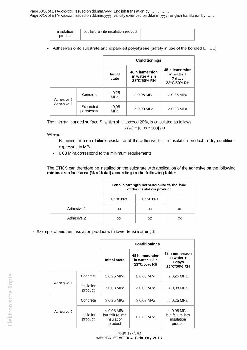
Page XXX of ETA-xx/xxxx, issued on dd.mm.yyyy, English translation by ……………Page XXX of ETA-xx/xxxx, issued on dd.mm.yyyy, validity extended on dd.mm.yyyy, English translation by ……
Page 127/143©EOTA_ETAG 004, February 2013
insulationproduct
but failure into insulation product
Adhesives onto substrate and expanded polystyrene (safety in use of the bonded ETICS)
Conditionings
Initialstate
48 h immersionin water + 2 h23°C/50% RH
48 h immersionin water +
7 days23°C/50% RH
Adhesive 1Adhesive 2
Concrete 0,25MPa 0,08 MPa 0,25 MPa
Expandedpolystyrene
0,08MPa 0,03 MPa 0,08 MPa
The minimal bonded surface S, which shall exceed 20%, is calculated as follows:S (%) = [0,03 * 100] / B
Where:- B: minimum mean failure resistance of the adhesive to the insulation product in dry conditions
expressed in MPa- 0,03 MPa correspond to the minimum requirements
The ETICS can therefore be installed on the substrate with application of the adhesive on the followingminimal surface area (% of total) according to the following table:
Tensile strength perpendicular to the faceof the insulation product
100 kPa 150 kPa ...
Adhesive 1 xx xx xx
Adhesive 2 xx xx xx
- Example of another insulation product with lower tensile strength
Conditionings
Initial state48 h immersionin water + 2 h23°C/50% RH
48 h immersionin water +
7 days23°C/50% RH
Adhesive 1
Concrete 0,25 MPa 0,08 MPa 0,25 MPa
Insulationproduct 0,08 MPa 0,03 MPa 0,08 MPa
Adhesive 2
Concrete 0,25 MPa 0,08 MPa 0,25 MPa
Insulationproduct
0,08 MPabut failure into
insulationproduct
0,03 MPa
0,08 MPabut failure into
insulationproduct
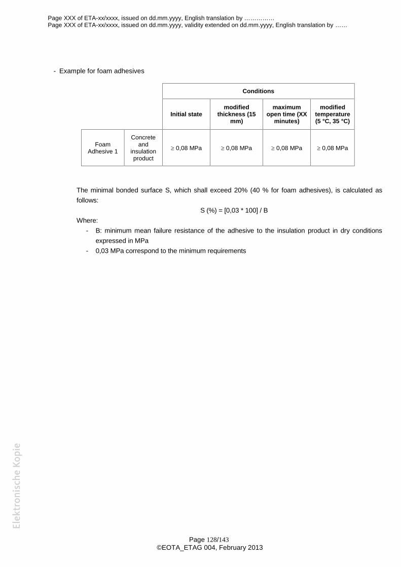
Page XXX of ETA-xx/xxxx, issued on dd.mm.yyyy, English translation by ……………Page XXX of ETA-xx/xxxx, issued on dd.mm.yyyy, validity extended on dd.mm.yyyy, English translation by ……
Page 128/143©EOTA_ETAG 004, February 2013
- Example for foam adhesives
Conditions
Initial statemodified
thickness (15mm)
maximumopen time (XX
minutes)
modifiedtemperature(5 °C, 35 °C)
FoamAdhesive 1
Concreteand
insulationproduct
0,08 MPa 0,08 MPa 0,08 MPa 0,08 MPa
The minimal bonded surface S, which shall exceed 20% (40 % for foam adhesives), is calculated asfollows:
S (%) = [0,03 * 100] / BWhere:
- B: minimum mean failure resistance of the adhesive to the insulation product in dry conditionsexpressed in MPa
- 0,03 MPa correspond to the minimum requirements
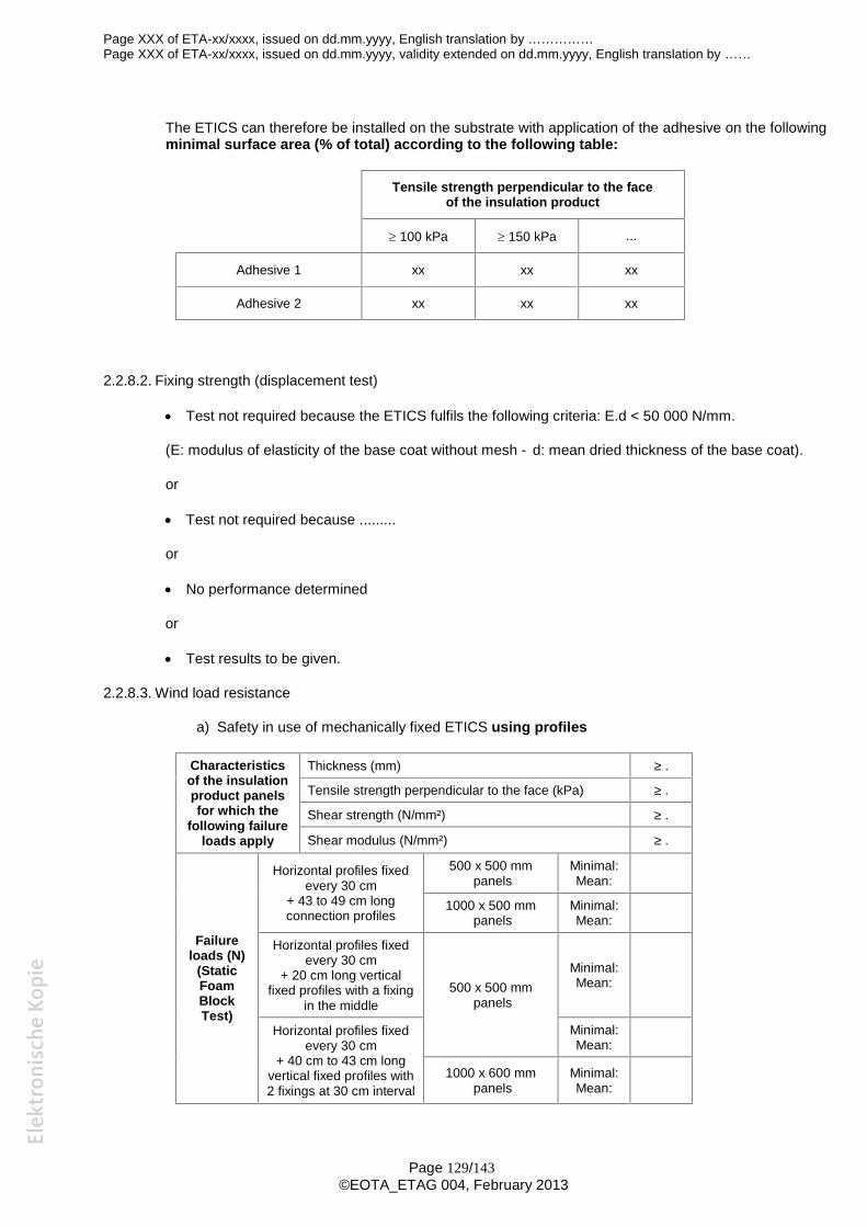
Page XXX of ETA-xx/xxxx, issued on dd.mm.yyyy, English translation by ……………Page XXX of ETA-xx/xxxx, issued on dd.mm.yyyy, validity extended on dd.mm.yyyy, English translation by ……
Page 129/143©EOTA_ETAG 004, February 2013
The ETICS can therefore be installed on the substrate with application of the adhesive on the followingminimal surface area (% of total) according to the following table:
Tensile strength perpendicular to the faceof the insulation product
100 kPa 150 kPa ...
Adhesive 1 xx xx xx
Adhesive 2 xx xx xx
2.2.8.2. Fixing strength (displacement test)
Test not required because the ETICS fulfils the following criteria: E.d < 50 000 N/mm.
(E: modulus of elasticity of the base coat without mesh - d: mean dried thickness of the base coat).
or
Test not required because .........
or
No performance determined
or
Test results to be given.
2.2.8.3. Wind load resistance
a) Safety in use of mechanically fixed ETICS using profiles
Characteristicsof the insulationproduct panelsfor which the
following failureloads apply
Thickness (mm) ≥ .
Tensile strength perpendicular to the face (kPa) ≥ .
Shear strength (N/mm²) ≥ .
Shear modulus (N/mm²) ≥ .
Failureloads (N)
(StaticFoamBlockTest)
Horizontal profiles fixedevery 30 cm
+ 43 to 49 cm longconnection profiles
500 x 500 mmpanels
Minimal:Mean:
1000 x 500 mmpanels
Minimal:Mean:
Horizontal profiles fixedevery 30 cm
+ 20 cm long verticalfixed profiles with a fixing
in the middle500 x 500 mm
panels
Minimal:Mean:
Horizontal profiles fixedevery 30 cm
+ 40 cm to 43 cm longvertical fixed profiles with2 fixings at 30 cm interval
Minimal:Mean:
1000 x 600 mmpanels
Minimal:Mean:
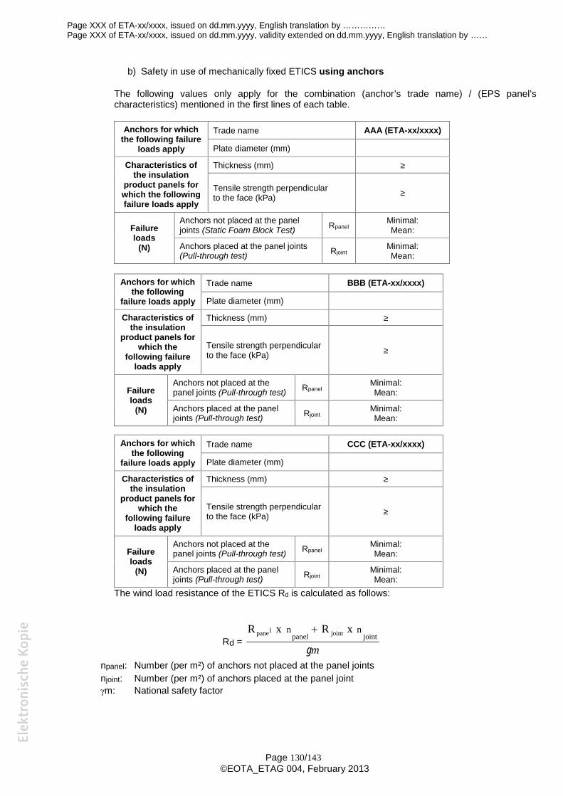
Page XXX of ETA-xx/xxxx, issued on dd.mm.yyyy, English translation by ……………Page XXX of ETA-xx/xxxx, issued on dd.mm.yyyy, validity extended on dd.mm.yyyy, English translation by ……
Page 130/143©EOTA_ETAG 004, February 2013
b) Safety in use of mechanically fixed ETICS using anchors
The following values only apply for the combination (anchor’s trade name) / (EPS panel’scharacteristics) mentioned in the first lines of each table.
Anchors for whichthe following failure
loads apply
Trade name AAA (ETA-xx/xxxx)
Plate diameter (mm)
Characteristics ofthe insulation
product panels forwhich the followingfailure loads apply
Thickness (mm) ≥
Tensile strength perpendicularto the face (kPa) ≥
Failureloads
(N)
Anchors not placed at the paneljoints (Static Foam Block Test) Rpanel
Minimal:Mean:
Anchors placed at the panel joints(Pull-through test) Rjoint
Minimal:Mean:
Anchors for whichthe following
failure loads apply
Trade name BBB (ETA-xx/xxxx)
Plate diameter (mm)
Characteristics ofthe insulation
product panels forwhich the
following failureloads apply
Thickness (mm) ≥
Tensile strength perpendicularto the face (kPa) ≥
Failureloads
(N)
Anchors not placed at thepanel joints (Pull-through test) Rpanel
Minimal:Mean:
Anchors placed at the paneljoints (Pull-through test) Rjoint
Minimal:Mean:
Anchors for whichthe following
failure loads apply
Trade name CCC (ETA-xx/xxxx)
Plate diameter (mm)
Characteristics ofthe insulation
product panels forwhich the
following failureloads apply
Thickness (mm) ≥
Tensile strength perpendicularto the face (kPa) ≥
Failureloads
(N)
Anchors not placed at thepanel joints (Pull-through test) Rpanel
Minimal:Mean:
Anchors placed at the paneljoints (Pull-through test) Rjoint
Minimal:Mean:
The wind load resistance of the ETICS Rd is calculated as follows:
Rd =m
jointpanelnn xRxR jointlpane
npanel: Number (per m²) of anchors not placed at the panel jointsnjoint: Number (per m²) of anchors placed at the panel jointm: National safety factor
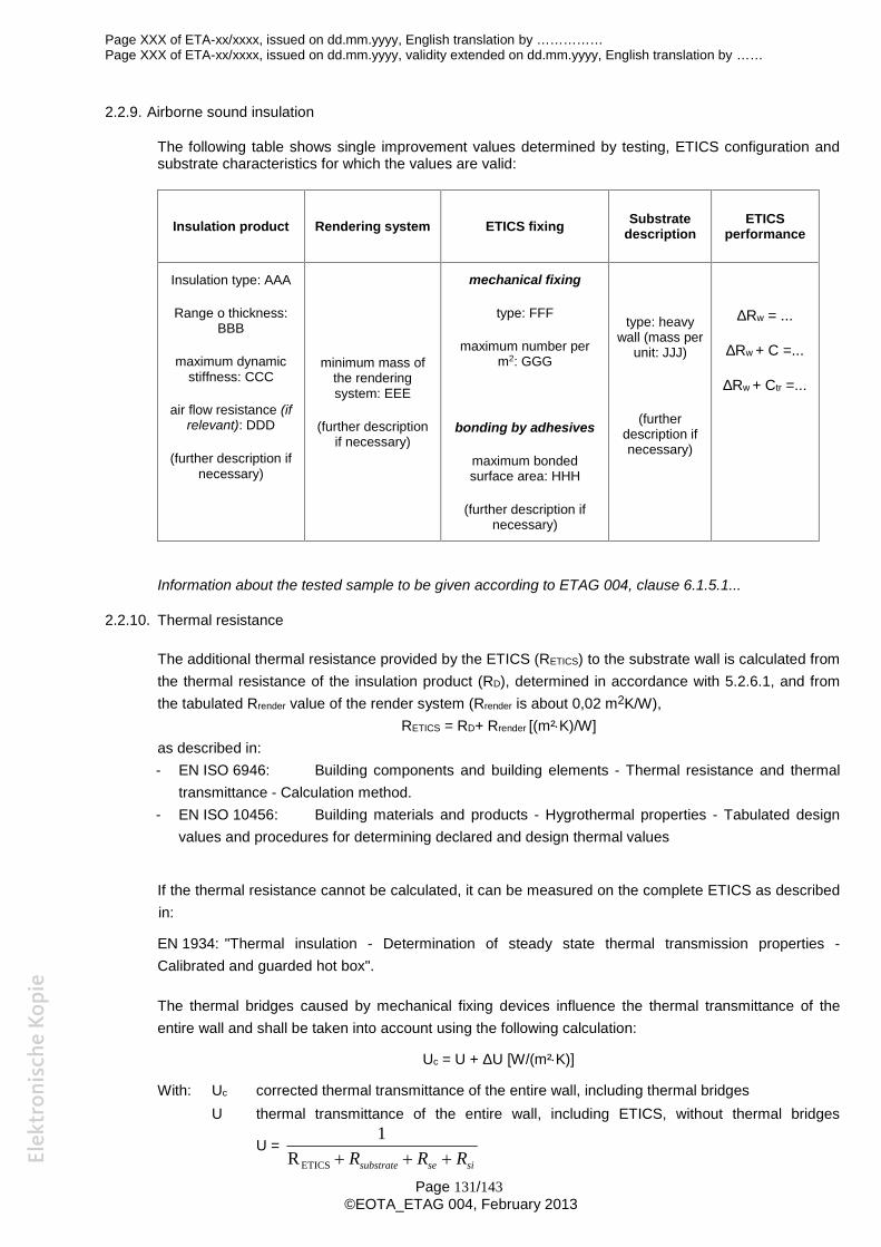
Page XXX of ETA-xx/xxxx, issued on dd.mm.yyyy, English translation by ……………Page XXX of ETA-xx/xxxx, issued on dd.mm.yyyy, validity extended on dd.mm.yyyy, English translation by ……
Page 131/143©EOTA_ETAG 004, February 2013
2.2.9. Airborne sound insulation
The following table shows single improvement values determined by testing, ETICS configuration andsubstrate characteristics for which the values are valid:
Insulation product Rendering system ETICS fixing Substratedescription
ETICSperformance
Insulation type: AAA
Range o thickness:BBB
maximum dynamicstiffness: CCC
air flow resistance (ifrelevant): DDD
(further description ifnecessary)
minimum mass ofthe renderingsystem: EEE
(further descriptionif necessary)
mechanical fixing
type: FFF
maximum number perm2: GGG
bonding by adhesives
maximum bondedsurface area: HHH
(further description ifnecessary)
type: heavywall (mass per
unit: JJJ)
(furtherdescription ifnecessary)
∆Rw = ...
∆Rw + C =...
∆Rw + Ctr =...
Information about the tested sample to be given according to ETAG 004, clause 6.1.5.1...
2.2.10. Thermal resistance
The additional thermal resistance provided by the ETICS (RETICS) to the substrate wall is calculated fromthe thermal resistance of the insulation product (RD), determined in accordance with 5.2.6.1, and fromthe tabulated Rrender value of the render system (Rrender is about 0,02 m2K/W),
RETICS = RD+ Rrender [(m²K)/W]as described in:- EN ISO 6946: Building components and building elements - Thermal resistance and thermal
transmittance - Calculation method.- EN ISO 10456: Building materials and products - Hygrothermal properties - Tabulated design
values and procedures for determining declared and design thermal values
If the thermal resistance cannot be calculated, it can be measured on the complete ETICS as describedin:
EN 1934: "Thermal insulation - Determination of steady state thermal transmission properties -Calibrated and guarded hot box".
The thermal bridges caused by mechanical fixing devices influence the thermal transmittance of theentire wall and shall be taken into account using the following calculation:
Uc = U + ΔU [W/(m²K)]
With: Uc corrected thermal transmittance of the entire wall, including thermal bridgesU thermal transmittance of the entire wall, including ETICS, without thermal bridges
U =sisesubstrate RRR ETICSR
1
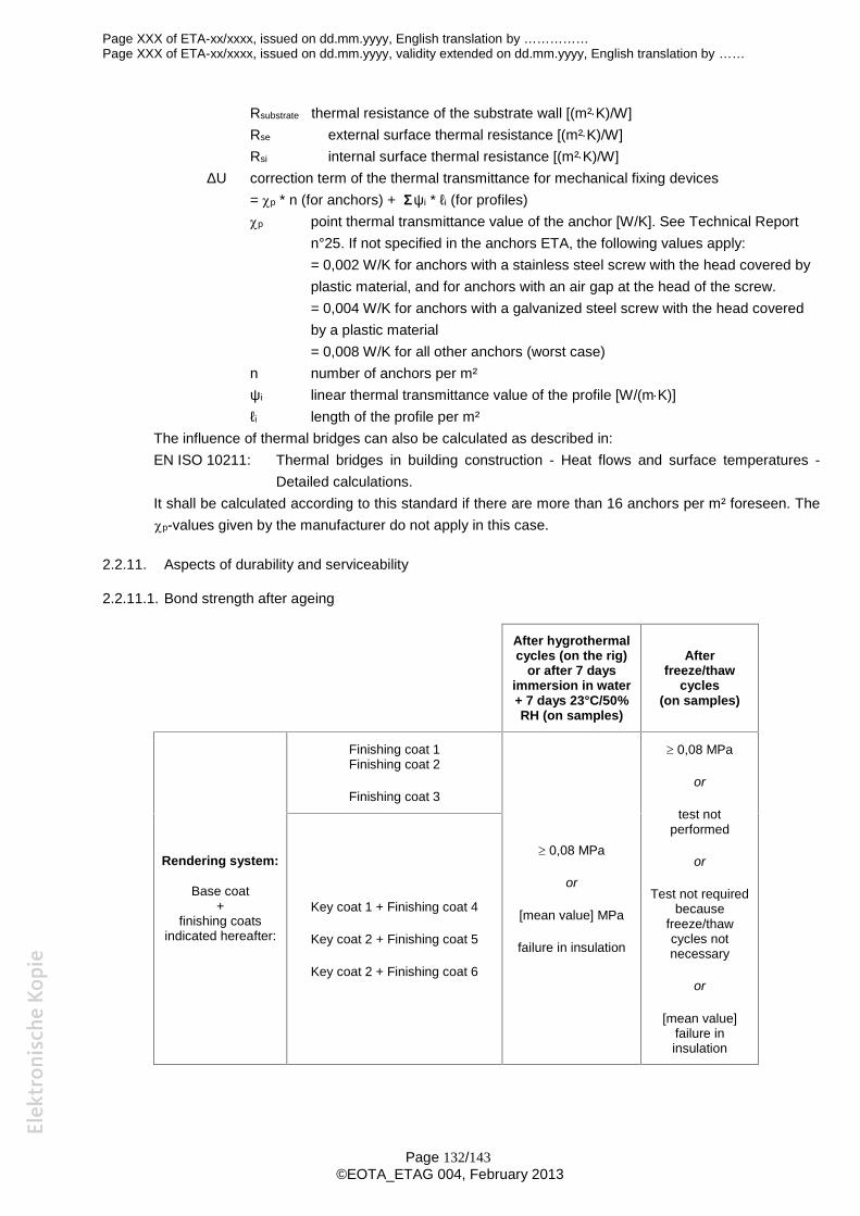
Page XXX of ETA-xx/xxxx, issued on dd.mm.yyyy, English translation by ……………Page XXX of ETA-xx/xxxx, issued on dd.mm.yyyy, validity extended on dd.mm.yyyy, English translation by ……
Page 132/143©EOTA_ETAG 004, February 2013
Rsubstrate thermal resistance of the substrate wall [(m²K)/W]Rse external surface thermal resistance [(m²K)/W]Rsi internal surface thermal resistance [(m²K)/W]
ΔU correction term of the thermal transmittance for mechanical fixing devices= p * n (for anchors) + Σψi * ℓi (for profiles)p point thermal transmittance value of the anchor [W/K]. See Technical Report
n°25. If not specified in the anchors ETA, the following values apply:= 0,002 W/K for anchors with a stainless steel screw with the head covered byplastic material, and for anchors with an air gap at the head of the screw.= 0,004 W/K for anchors with a galvanized steel screw with the head coveredby a plastic material= 0,008 W/K for all other anchors (worst case)
n number of anchors per m²ψi linear thermal transmittance value of the profile [W/(mK)]ℓi length of the profile per m²
The influence of thermal bridges can also be calculated as described in:EN ISO 10211: Thermal bridges in building construction - Heat flows and surface temperatures -
Detailed calculations.It shall be calculated according to this standard if there are more than 16 anchors per m² foreseen. Thep-values given by the manufacturer do not apply in this case.
2.2.11. Aspects of durability and serviceability
2.2.11.1. Bond strength after ageing
After hygrothermalcycles (on the rig)
or after 7 daysimmersion in water+ 7 days 23°C/50%RH (on samples)
Afterfreeze/thaw
cycles(on samples)
Rendering system:
Base coat+
finishing coatsindicated hereafter:
Finishing coat 1Finishing coat 2
Finishing coat 3
0,08 MPa
or
[mean value] MPa
failure in insulation
0,08 MPa
or
test notperformed
or
Test not requiredbecause
freeze/thawcycles notnecessary
or
[mean value]failure ininsulation
Key coat 1 + Finishing coat 4
Key coat 2 + Finishing coat 5
Key coat 2 + Finishing coat 6
Page XXX of ETA-xx/xxxx, issued on dd.mm.yyyy, English translation by ……………Page XXX of ETA-xx/xxxx, issued on dd.mm.yyyy, validity extended on dd.mm.yyyy, English translation by ……
Page 133/143©EOTA_ETAG 004, February 2013
2.3. Components’ characteristics
2.3.1. Insulation product (example for an expanded polystyrene)
“Succinct description to be given”. Examples are given following:
Expanded polystyrene panels for bonded ETICS or mechanically fixed ETICS with anchors.
Factory-prefabricated, uncoated boards with right edges, made of expanded polystyrene (EPS)according to EN 13163 and having the description and characteristics defined in the table below.
Expanded polystyrene panels for mechanically fixed ETICS with profiles.
Factory-prefabricated, uncoated boards with grooved edges, made of expanded polystyrene (EPS)according to EN 13163 and having the description and characteristics defined in the table below.
- For each following characteristic, specify designation code according to EN or specific values incase of :- more “severe” ETA-holder’s requirements,- no existing designation code.
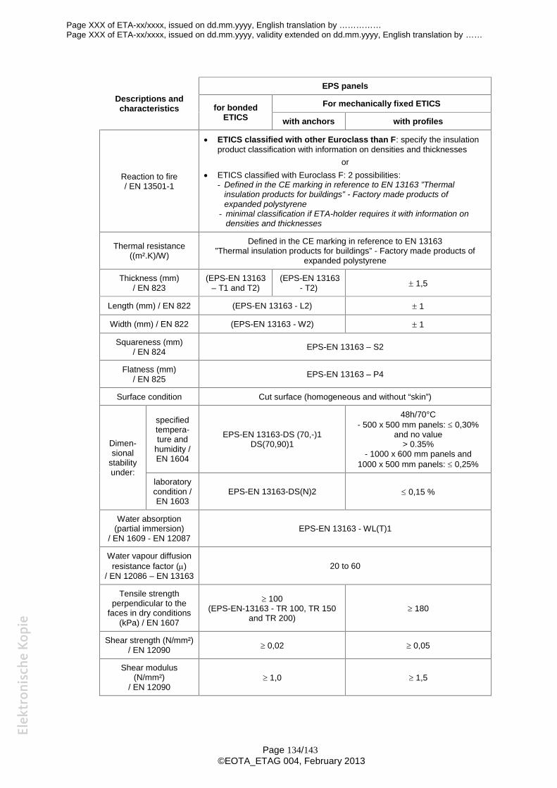
Page XXX of ETA-xx/xxxx, issued on dd.mm.yyyy, English translation by ……………Page XXX of ETA-xx/xxxx, issued on dd.mm.yyyy, validity extended on dd.mm.yyyy, English translation by ……
Page 134/143©EOTA_ETAG 004, February 2013
Descriptions andcharacteristics
EPS panels
for bondedETICS
For mechanically fixed ETICS
with anchors with profiles
Reaction to fire/ EN 13501-1
ETICS classified with other Euroclass than F: specify the insulationproduct classification with information on densities and thicknesses
or ETICS classified with Euroclass F: 2 possibilities:
- Defined in the CE marking in reference to EN 13163 ”Thermalinsulation products for buildings” - Factory made products ofexpanded polystyrene
- minimal classification if ETA-holder requires it with information ondensities and thicknesses
Thermal resistance((m².K)/W)
Defined in the CE marking in reference to EN 13163”Thermal insulation products for buildings” - Factory made products of
expanded polystyrene
Thickness (mm)/ EN 823
(EPS-EN 13163– T1 and T2)
(EPS-EN 13163- T2) 1,5
Length (mm) / EN 822 (EPS-EN 13163 - L2) 1
Width (mm) / EN 822 (EPS-EN 13163 - W2) 1
Squareness (mm)/ EN 824 EPS-EN 13163 – S2
Flatness (mm)/ EN 825 EPS-EN 13163 – P4
Surface condition Cut surface (homogeneous and without “skin”)
Dimen-sional
stabilityunder:
specifiedtempera-ture and
humidity /EN 1604
EPS-EN 13163-DS (70,-)1DS(70,90)1
48h/70°C- 500 x 500 mm panels: 0,30%
and no value> 0.35%
- 1000 x 600 mm panels and1000 x 500 mm panels: 0,25%
laboratorycondition /EN 1603
EPS-EN 13163-DS(N)2 0,15 %
Water absorption(partial immersion)
/ EN 1609 - EN 12087EPS-EN 13163 - WL(T)1
Water vapour diffusionresistance factor ()
/ EN 12086 – EN 1316320 to 60
Tensile strengthperpendicular to the
faces in dry conditions(kPa) / EN 1607
100(EPS-EN-13163 - TR 100, TR 150
and TR 200) 180
Shear strength (N/mm²)/ EN 12090 0,02 0,05
Shear modulus(N/mm²)
/ EN 12090 1,0 1,5
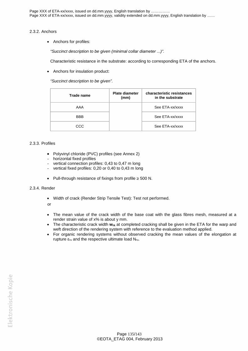
Page XXX of ETA-xx/xxxx, issued on dd.mm.yyyy, English translation by ……………Page XXX of ETA-xx/xxxx, issued on dd.mm.yyyy, validity extended on dd.mm.yyyy, English translation by ……
Page 135/143©EOTA_ETAG 004, February 2013
2.3.2. Anchors
Anchors for profiles:
“Succinct description to be given (minimal collar diameter ...)”.
Characteristic resistance in the substrate: according to corresponding ETA of the anchors.
Anchors for insulation product:
“Succinct description to be given”.
Trade name Plate diameter(mm)
characteristic resistancesin the substrate
AAA See ETA-xx/xxxx
BBB See ETA-xx/xxxx
CCC See ETA-xx/xxxx
2.3.3. Profiles
Polyvinyl chloride (PVC) profiles (see Annex 2)- horizontal fixed profiles- vertical connection profiles: 0,43 to 0,47 m long- vertical fixed profiles: 0,20 or 0,40 to 0,43 m long
Pull-through resistance of fixings from profile ≥ 500 N.
2.3.4. Render
Width of crack (Render Strip Tensile Test): Test not performed.or
The mean value of the crack width of the base coat with the glass fibres mesh, measured at arender strain value of x% is about y mm.
The characteristic crack width wrk at completed cracking shall be given in the ETA for the warp andweft direction of the rendering system with reference to the evaluation method applied.
For organic rendering systems without observed cracking the mean values of the elongation atrupture εru and the respective ultimate load Nru.
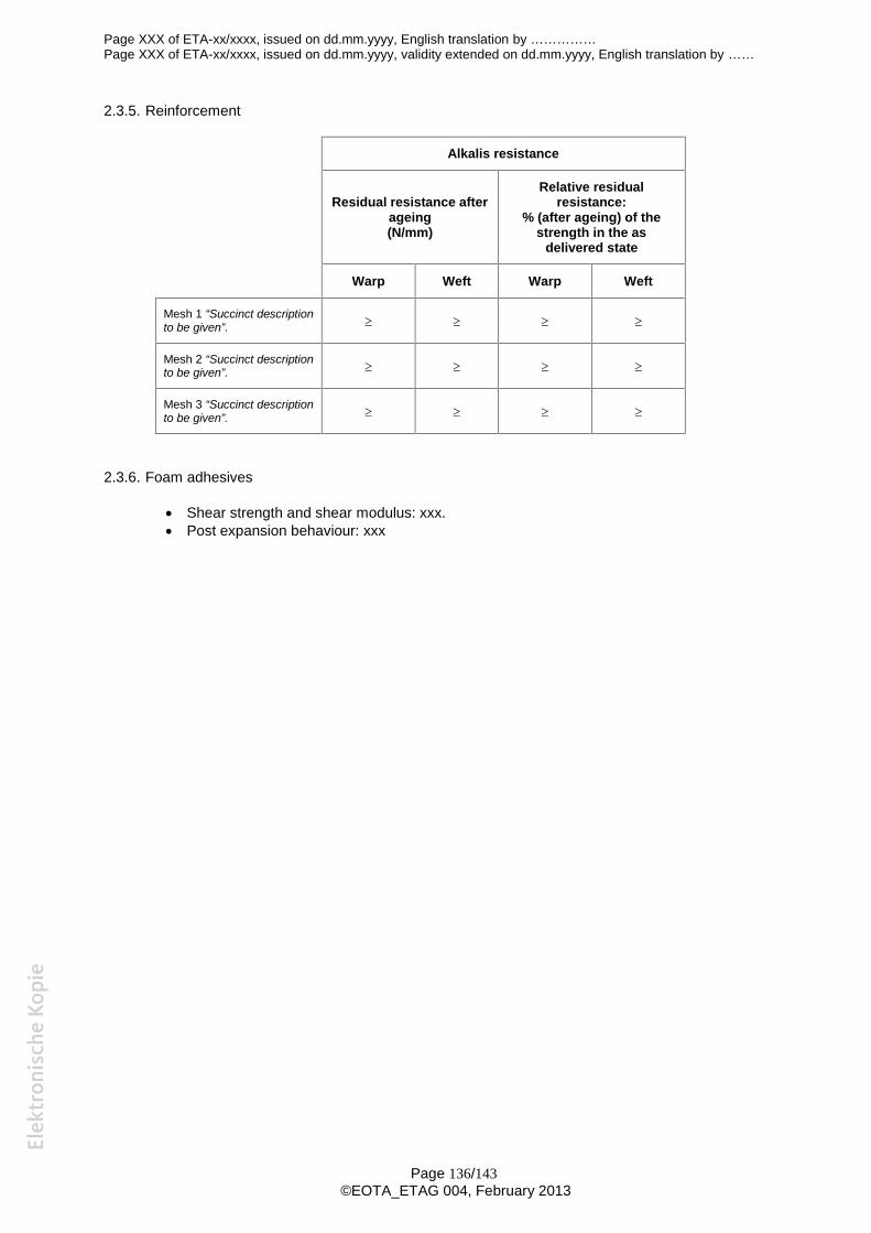
Page XXX of ETA-xx/xxxx, issued on dd.mm.yyyy, English translation by ……………Page XXX of ETA-xx/xxxx, issued on dd.mm.yyyy, validity extended on dd.mm.yyyy, English translation by ……
Page 136/143©EOTA_ETAG 004, February 2013
2.3.5. Reinforcement
Alkalis resistance
Residual resistance afterageing(N/mm)
Relative residualresistance:
% (after ageing) of thestrength in the as
delivered state
Warp Weft Warp Weft
Mesh 1 “Succinct descriptionto be given”.
Mesh 2 “Succinct descriptionto be given”.
Mesh 3 “Succinct descriptionto be given”.
2.3.6. Foam adhesives
Shear strength and shear modulus: xxx. Post expansion behaviour: xxx
Page XXX of ETA-xx/xxxx, issued on dd.mm.yyyy, English translation by ……………Page XXX of ETA-xx/xxxx, issued on dd.mm.yyyy, validity extended on dd.mm.yyyy, English translation by ……
Page 137/143©EOTA_ETAG 004, February 2013
3. Evaluation and attestation of Conformity and CE marking
3.1. System of attestation of conformity
According to the decision 97/556/EC of the European Commission, the system 2+ of attestation ofconformity applies.
In addition, according to the decision 2001/596/EC of the European Commission, the systems 1 and2+ of attestation of conformity apply with regard to reaction to fire.
Considering any Euroclass for the reaction to fire, the system of attestation of conformity, regardingother characteristics than reaction to fire, is system 2+. This system is described in the CouncilDirective 89/106/EEC Annex III, 2 (ii), First possibility as follows:
Declaration of conformity of the ETICS by the manufacturer on the basis of:
a) Tasks for the manufacturer:1 - Initial type-testing of the ETICS and the components2 - Factory Production Control3 - Testing of samples taken at the factory in accordance with a prescribed test plan.
b) Tasks for the Notified Body:4 - Certification of factory production control on the basis of:
- Initial inspection of factory and of factory production control- Continuous surveillance, assessment and approval of factory production control.
Considering the Euroclass (A1, A2, B or C) for reaction to fire while a clearly identifiable stage in theproduction process results in an improvement of the reaction to fire classification, the system ofattestation of conformity, regarding reaction to fire characteristic, is system 1. This system 1 isdescribed in the Council Directive 89/106/EEC Annex III, 2 (i), as follows:
Page XXX of ETA-xx/xxxx, issued on dd.mm.yyyy, English translation by ……………Page XXX of ETA-xx/xxxx, issued on dd.mm.yyyy, validity extended on dd.mm.yyyy, English translation by ……
Page 138/143©EOTA_ETAG 004, February 2013
Certification of the conformity of the ETICS by a Notified Body on the basis of:
a) Tasks for the manufacturer:1 - Factory Production Control2 - Further testing of samples taken at the factory by the manufacturer in accordance with a
prescribed test plan.
b) Tasks for the Notified Body:3 - Initial type-testing of the ETICS and the components,4 - Initial inspection of factory and of factory production control,5 - Continuous surveillance, assessment and approval of factory production control.
3.2. Responsibilities
3.2.1 Tasks of the manufacturer
3.2.1.1. Factory production control
The manufacturer shall exercise permanent internal control of production. All the elements,requirements and provisions adopted by the manufacturer shall be documented in a systematic mannerin the form of written policies and procedures, including records of results performed. This productioncontrol system shall ensure that the product is in conformity with this European Technical Approval.
The manufacturer may only use components stated in the technical documentation of this EuropeanTechnical Approval including Control Plan.
For the components of the ETICS which the ETA-holder does not manufacture by himself, he shallmake sure that factory production control carried out by the other manufacturers gives the guarantee ofthe components compliance with the European Technical Approval.
The factory production control and the provisions taken by the ETA-holder for components not producedby himself shall be in accordance with the “Control Plan relating to this European Technical Approvalwhich is part of the technical documentation of this European Technical Approval. The “Control Plan1)” islaid down in the context of the factory production control system operated by the manufacturer anddeposited at the ……. (name of the Approval Body).
The results of factory production control shall be recorded and evaluated in accordance with theprovisions of the “Control Plan1)”.
3.2.1.2. Other tasks of manufacturer
The manufacturer shall, on the basis of a contract, involve a body (bodies) which is (are) notified for thetasks referred to in section 3.1 in the field of ETICS in order to undertake the actions laid down insection 3.3. For this purpose, the “Control Plan”1) referred to in sections 3.2.1.1 and 3.2.2 shall behanded over by the manufacturer to the Notified Body or Bodies involved.
For initial type testing (in case of system 2+), the results of the tests performed as part of theassessment for the European Technical Approval can be used unless there are changes in theproduction line or plant.
The manufacturer shall make a declaration of conformity, stating that the construction product is inconformity with the provisions of this European Technical Approval. The initial type-testing mentionedabove could be taken over by the manufacturer for this declaration.
3.2.2 Tasks of Notified Bodies
The Notified Body (Bodies) shall perform the:
1) The Control Plan is a confidential part of the European Technical Approval and only handed over to the notified body orbodies involved in the procedure of attestation of conformity. See section 3.2.2.
Page XXX of ETA-xx/xxxx, issued on dd.mm.yyyy, English translation by ……………Page XXX of ETA-xx/xxxx, issued on dd.mm.yyyy, validity extended on dd.mm.yyyy, English translation by ……
Page 139/143©EOTA_ETAG 004, February 2013
- initial type-testing of the product (for system 1)The results of the tests performed as part of the assessment for the European Technical Approval canbe used unless there are changes in the production line or plant. In such cases, the necessary initialtype testing has to be agreed between the “Name of the Approval Body” and the Notified Bodyinvolved.
- initial inspection of factory and of factory production controlThe Notified Body shall ascertain that, in accordance with the Control Plan1, the factory (in particularthe employees and the equipment) and the factory production control are suitable to ensurecontinuous and orderly manufacturing of the components according to the specifications mentioned inclause 2 of this ETA.
- continuous surveillance, assessment and approval of factory production controlThe Notified Body shall visit the factory:* at least twice a year for surveillance. By further agreement between the “Name of Approval Body”
and the Notified Body involved, this frequency can be reduced to one a year after a probationaryperiod,
or
* at least once a year for surveillance of this manufacturer having a FPC system complying with ENISO 9001 covering the manufacturing of the ETICS components.It has to be verified that the system of factory production control and the specified automatedmanufacturing process are maintained taking into account the Control Plan1).
These tasks shall be performed in accordance with the provisions laid down in the “Control Plan1) ofthis European Technical Approval”.
All ETICS characteristics are of interest to the Notified Body but in particular reaction to fire and bondstrength.
The Notified Body shall retain the essential points of its actions referred to above and state the resultsobtained and conclusions drawn in (a) written report (reports).
In the case of Attestation of Conformity system 1:
The Notified Body involved by the manufacturer shall issue an EC certificate of conformity of theproduct stating the conformity with the provisions of this European Technical Approval.
In the case of Attestation of Conformity system 2+:
The Notified Body involved by the manufacturer shall issue an EC certificate of conformity of thefactory production control stating the conformity with the provisions of this European TechnicalApproval.
In cases where the provisions of the European Technical Approval and its “Control Plan1)” are no longerfulfilled, the Notified Body shall withdraw the certificate of conformity and inform …….. (name of theApproval Body) without delay.
1) The Control Plan is a confidential part of the European Technical Approval and only handed over to the notified body orbodies involved in the procedure of attestation of conformity. See section 3.2.2.
Page XXX of ETA-xx/xxxx, issued on dd.mm.yyyy, English translation by ……………Page XXX of ETA-xx/xxxx, issued on dd.mm.yyyy, validity extended on dd.mm.yyyy, English translation by ……
Page 140/143©EOTA_ETAG 004, February 2013
3.3. CE marking
The CE marking shall be affixed either on the product itself, on a label attached to it, on its packaging oron the commercial documents accompanying the components of the ETICS. The letters « CE » shall befollowed by the identification number of the Notified Body involved and be accompanied by the followingadditional information:
- the identification number of the Notified Body- the name or identifying mark and address of the ETA-holder,- the last two digits of the year in which the CE marking was affixed,- the number of the EC certificate of conformity of Factory Production Control (system 2+),- the number of the EC certificate of conformity for the ETICS (system 1),- the number of the European Technical Approval,- the ETICS trade name,- the number of the ETAG.
4. Assumptions under which the fitness of the product for the intended use was favourablyassessed
4.1 Manufacturing
The European Technical Approval is issued for the ETICS on the basis of agreed data/information,deposited with the ….. (Approval Body name), which identifies the ETICS that has been assessed andjudged. Changes to the ETICS or production process, which could result in this depositeddata/information being incorrect, shall be notified to the …… (Approval Body name) before the changesare introduced. The …………. (Approval Body name) will decide whether or not such changes affect theETA and consequently the validity of the CE marking on the basis of the ETA and if so whether furtherassessment or alterations to the ETA, shall be necessary.
4.2 Installation
The assessment of the ETICS was based on an assumed way of design, installation and execution,transport and storage, use, maintenance and repair. The assumptions and further recommendations arelaid down in chapter 7 of ETAG 004.
Design, installation and execution are to be in conformity with national documents. However, thesedocuments and the level of their implementation in Member States’ legislation are different. The chapter 7of ETAG 004 summarizes how information introduced in ETAs and related documents is intended to beused in the construction process and gives advice to all parties interested when normative documents aremissing.
5. Indications to the manufacturers.
5.1 Packaging, transport and storage
Packaging of the components has to be such that the products are protected from moisture duringtransport and storage, unless other measures are foreseen by the manufacturer for this purpose.
The components have to be protected against damage.
It is the responsibility of the manufacturer(s) to ensure that information relating to packaging (if relevant),protection against damage, and storage are made know to the concerned people.
5.2 Use, maintenance and repair
The finishing coat shall normally be maintained in order to fully preserve the ETICS’s performance.
Maintenance includes at least:- visual inspection of the ETICS- the repairing of localised damaged areas due to accidents,
Page XXX of ETA-xx/xxxx, issued on dd.mm.yyyy, English translation by ……………Page XXX of ETA-xx/xxxx, issued on dd.mm.yyyy, validity extended on dd.mm.yyyy, English translation by ……
Page 141/143©EOTA_ETAG 004, February 2013
- the aspect maintenance with products adapted and compatible with the ETICS (possibly after washingor ad hoc preparation).
Necessary repairs should be performed as soon as the need has been identified.
It is important to be able to carry out maintenance as far as possible using readily available products andequipment, without spoiling appearance. Only products which are compatible with the ETICS shall beused
It is the responsibility of the manufacturer(s) to ensure that these provisions are easily accessible to theconcerned people.
The original Czech version is signed byName of the « Approval Body »
representative
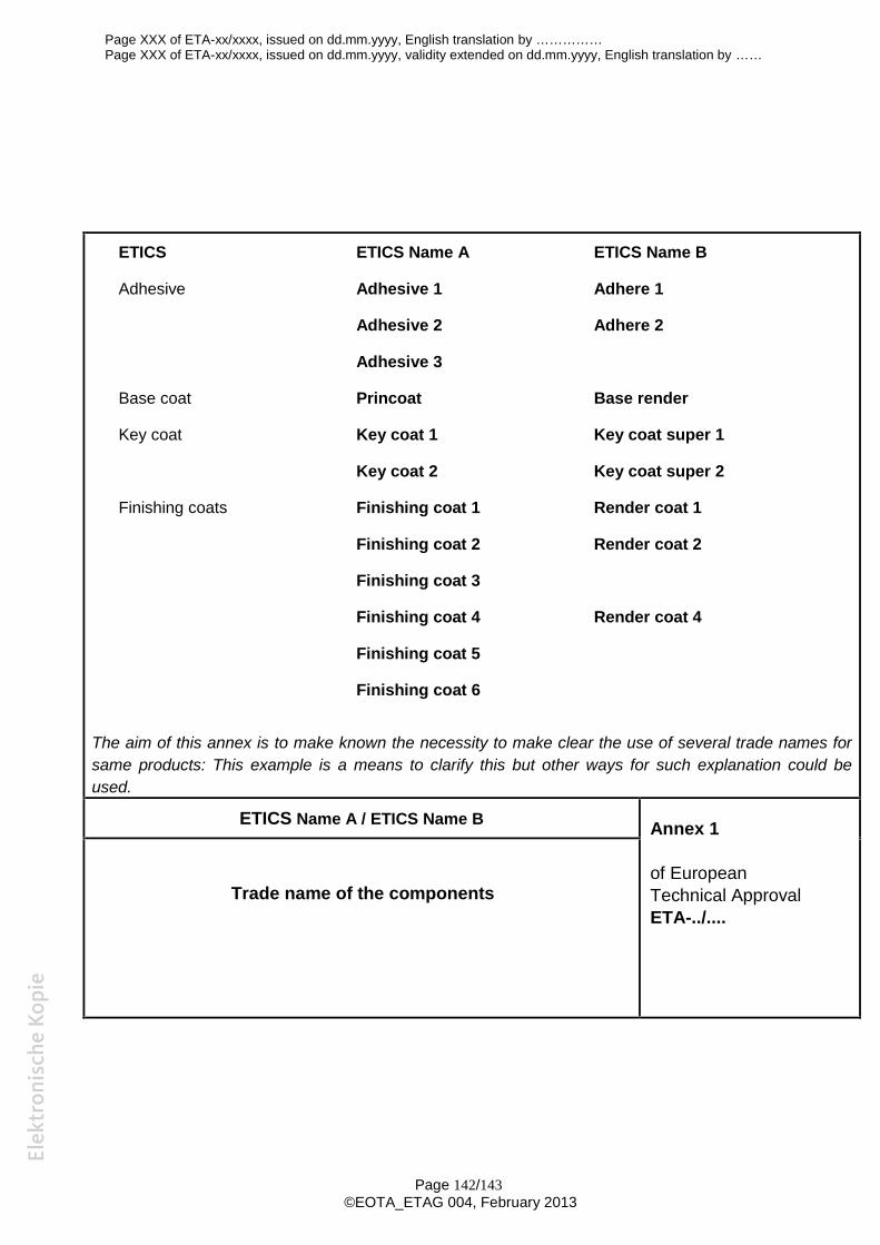
Page XXX of ETA-xx/xxxx, issued on dd.mm.yyyy, English translation by ……………Page XXX of ETA-xx/xxxx, issued on dd.mm.yyyy, validity extended on dd.mm.yyyy, English translation by ……
Page 142/143©EOTA_ETAG 004, February 2013
ETICS ETICS Name A ETICS Name B
Adhesive Adhesive 1 Adhere 1
Adhesive 2 Adhere 2
Adhesive 3
Base coat Princoat Base render
Key coat Key coat 1 Key coat super 1
Key coat 2 Key coat super 2
Finishing coats Finishing coat 1 Render coat 1
Finishing coat 2 Render coat 2
Finishing coat 3
Finishing coat 4 Render coat 4
Finishing coat 5
Finishing coat 6
The aim of this annex is to make known the necessity to make clear the use of several trade names forsame products: This example is a means to clarify this but other ways for such explanation could beused.
ETICS Name A / ETICS Name B Annex 1
of EuropeanTechnical ApprovalETA-../....
Trade name of the components
Page XXX of ETA-xx/xxxx, issued on dd.mm.yyyy, English translation by ……………Page XXX of ETA-xx/xxxx, issued on dd.mm.yyyy, validity extended on dd.mm.yyyy, English translation by ……
Page 143/143©EOTA_ETAG 004, February 2013
Insert drawings of the PVC profilesdefining the geometrical characteristics
ETICS Name A / ETICS Name B Annex 2
of EuropeanTechnical ApprovalETA-../....
Polyvinyl chloride profiles