Embed Size (px)
Citation preview

© CopyrightNachdruck verboten!
Reproduction prohibited!Réproduction interdit!
Prohibida toda reproducción.
Für weiteren Gebrauch aufbewahren!Keep this manual for future needs!Gardez ce mode d’emploi pour desutilisations ultérieures!Guarde este manual para posteriores usos.
BEDIENUNGSANLEITUNGUSER MANUAL
MODE D'EMPLOIMANUAL DEL USUARIO
DJ-HEAD 575 SPOTPro-Head-Spot
51839570_V_1_0.DOC2/97
MULTI-LANGUAGE-INSTRUCTIONS
Inhaltsverzeichnis/Table of contentsSommaire/Contenido
EINFÜHRUNG................................................................................................................................................... 4Lieferumfang .................................................................................................................................................. 4
SICHERHEITSHINWEISE................................................................................................................................. 5BESTIMMUNGSGEMÄßE VERWENDUNG..................................................................................................... 6GERÄTEBESCHREIBUNG .............................................................................................................................. 8
Features ......................................................................................................................................................... 8Geräteübersicht.............................................................................................................................................. 9
INSTALLATION .............................................................................................................................................. 10Lampeninstallation/Lampenwechsel ............................................................................................................ 10Lampenjustierung......................................................................................................................................... 11Einsetzen/Austauschen von Gobos............................................................................................................. 11Projektormontage......................................................................................................................................... 12Anschluss an den DMX-512 Controller / Verbindung Projektor – Projektor ................................................ 13Anschluss ans Netz ..................................................................................................................................... 14
BEDIENUNG ................................................................................................................................................... 15Stand Alone-Betrieb..................................................................................................................................... 15DMX-gesteuerter Betrieb ............................................................................................................................. 15Adressierung des Projektors........................................................................................................................ 15DMX-Protokoll .............................................................................................................................................. 16Control Board ............................................................................................................................................... 19Hauptfunktionen........................................................................................................................................... 19SPEC - Spezialfunktionen............................................................................................................................ 20Fehlermeldungen ......................................................................................................................................... 24
REINIGUNG UND WARTUNG........................................................................................................................ 26Sicherungswechsel ...................................................................................................................................... 27
TECHNISCHE DATEN.................................................................................................................................... 27
INTRODUCTION ............................................................................................................................................. 28Delivery includes.......................................................................................................................................... 28
SAFETY INSTRUCTIONS .............................................................................................................................. 29OPERATING DETERMINATIONS.................................................................................................................. 30DESCRIPTION OF THE DEVICE ................................................................................................................... 31
Features ....................................................................................................................................................... 31Overview ...................................................................................................................................................... 32
INSTALLATION .............................................................................................................................................. 33Installing/Replacing the lamp ....................................................................................................................... 33Lamp adjustment.......................................................................................................................................... 34Inserting/Exchanging gobos......................................................................................................................... 34Rigging ......................................................................................................................................................... 35DMX-512 connection / connection between fixtures.................................................................................... 36Connection with the mains........................................................................................................................... 37
OPERATION ................................................................................................................................................... 38Stand Alone operation ................................................................................................................................. 38DMX-controlled operation ............................................................................................................................ 38Addressing ................................................................................................................................................... 38DMX-protocol ............................................................................................................................................... 39Control Board ............................................................................................................................................... 42Main functions .............................................................................................................................................. 42SPEC -Special functions.............................................................................................................................. 43Error Messages............................................................................................................................................ 47
CLEANING AND MAINTENANCE ................................................................................................................. 48Replacing the fuse ....................................................................................................................................... 49
TECHNICAL SPECIFICATIONS..................................................................................................................... 50
51839570_V_1_0.DOC3/97
INTRODUCTION ............................................................................................................................................. 51Inclus dans la livraison................................................................................................................................. 51
INSTRUCTIONS DE SÉCURITÉ .................................................................................................................... 52EMPLOI SELON LES PRESCRIPTIONS....................................................................................................... 53DESCRIPTION DE L'APPAREIL.................................................................................................................... 55
Features ....................................................................................................................................................... 55Aperçue des parties ..................................................................................................................................... 56
INSTALLATION .............................................................................................................................................. 57Installer/Remplacer la lampe ....................................................................................................................... 57Ajustage de la lampe ................................................................................................................................... 58Introduire/échanger gobos ........................................................................................................................... 58Montage du projecteur ................................................................................................................................. 59Connexions au contrôleur DMX-512 / raccord projecteur - projecteur ........................................................ 60Alimentation ................................................................................................................................................. 61
MANIEMENT................................................................................................................................................... 62Opération Stand Alone................................................................................................................................. 62Contrôle par DMX ........................................................................................................................................ 62Codage du projecteur .................................................................................................................................. 62Protocôle DMX............................................................................................................................................. 63Control Board ............................................................................................................................................... 66Fonctions principales ................................................................................................................................... 66SPEC - fonctions speciales.......................................................................................................................... 67Avis d'erreur et d'information ....................................................................................................................... 71
NETTOYAGE ET MAINTENANCE................................................................................................................. 72Remplacer le fusible .................................................................................................................................... 73
CARACTÉRISTIQUES TECHNIQUES........................................................................................................... 74
INTRODUCCIÓN............................................................................................................................................. 75Inlcluido en la entraga.................................................................................................................................. 75
INSTRUCCIONES DE SEGURIDAD .............................................................................................................. 76INSTRUCCIONES DE MANEJO .................................................................................................................... 77DESCRIPCIÓN DEL APARATO..................................................................................................................... 78
Features ....................................................................................................................................................... 78Descripción de las partes............................................................................................................................. 79
INSTALACIÓN ................................................................................................................................................ 80Instalar/Reemplazar la lámpara ................................................................................................................... 80Ajuste de la lámpara .................................................................................................................................... 81Insertar/reemplazar gobos ........................................................................................................................... 81Montaje del proyector .................................................................................................................................. 82Conexión al controlador DMX / conexión proyector - proyector .................................................................. 83Alimentación................................................................................................................................................. 84
OPERACIÓN ................................................................................................................................................... 85Operación Stand Alone................................................................................................................................ 85Control por DMX .......................................................................................................................................... 85Direccionamiento del proyector ................................................................................................................... 85Protócolo DMX............................................................................................................................................. 86Control Board ............................................................................................................................................... 89Funciones principales .................................................................................................................................. 89SPEC - Funciones especiales ..................................................................................................................... 90Avisos de error ............................................................................................................................................. 94
LIMPIEZA Y MANTENIMIENTO..................................................................................................................... 95Reemplazar el fusible .................................................................................................................................. 96
ESPECIFICACIONES TÉCNICAS.................................................................................................................. 97
Das neueste Update dieser Bedienungsanleitung finden Sie im Internet unter:You can find the latest update of this user manual in the Internet under:
Vous pouvez trouvez la dernière version de ce mode d'emploi dans l'Internet sous:Vd. puede encontrar la versión más reciente de este manual en el Internet bajo:
www.futurelight.com

51839570_V_1_0.DOC4/97
BEDIENUNGSANLEITUNG
DJ-HEAD 575 SPOTPro-Head-Spot
Lesen Sie vor der ersten Inbetriebnahme zur eigenen Sicherheit diese Bedienungsanleitungsorgfältig durch!
Alle Personen, die mit der Aufstellung, Inbetriebnahme, Bedienung, Wartung und Instandhaltung diesesGerätes zu tun haben, müssen- entsprechend qualifiziert sein- diese Bedienungsanleitung genau beachten- die Bedienungsanleitung als Teil des Produkts betrachten- die Bedienungsanleitung während der Lebensdauer des Produkts behalten- die Bedienungsanleitung an jeden nachfolgenden Besitzer oder Benutzer des Produkts weitergeben- sich die letzte Version der Anleitung im Internet herunter laden
EINFÜHRUNGWir freuen uns, dass Sie sich für einen FUTURELIGHT DJ-HEAD 575 SPOT entschieden haben. Sie habenhiermit ein leistungsstarkes und vielseitiges Gerät erworben.
Nehmen Sie den DJ-HEAD 575 SPOT aus der Verpackung.
Lieferumfang
1 Gerät1 Bedienungsanleitung1 Kabel MC-50, 5m, schwarz,XLR m/f,symmetr. 3022050N2 Montagehalter

51839570_V_1_0.DOC5/97
SICHERHEITSHINWEISE
ACHTUNG!Seien Sie besonders vorsichtig beim Umgang mit gefährlicher Netzspannung. Bei die-ser Spannung können Sie einen lebensgefährlichen elektrischen Schlag erhalten!
Dieses Gerät hat das Werk in sicherheitstechnisch einwandfreiem Zustand verlassen. Um diesen Zustand zuerhalten und einen gefahrlosen Betrieb sicherzustellen, muss der Anwender die Sicherheitshinweise und dieWarnvermerke unbedingt beachten, die in dieser Bedienungsanleitung enthalten sind.
Unbedingt lesen:Bei Schäden, die durch Nichtbeachtung der Anleitung verursacht werden, erlischt der Garantiean-spruch. Für daraus resultierende Folgeschäden übernimmt der Hersteller keine Haftung.
Das Gerät darf nicht in Betrieb genommen werden, nachdem es von einem kalten in einen warmen Raumgebracht wurde. Das dabei entstehende Kondenswasser kann unter Umständen Ihr Gerät zerstören. LassenSie das Gerät solange uneingeschaltet, bis es Zimmertemperatur erreicht hat!
Bitte überprüfen Sie vor der ersten Inbetriebnahme, ob kein offensichtlicher Transportschaden vorliegt.Sollten Sie Schäden an der Netzleitung oder am Gehäuse entdecken, nehmen Sie das Gerät nicht in Betriebund setzen sich bitte mit Ihrem Fachhändler in Verbindung.
Der Aufbau entspricht der Schutzklasse I. Der Netzstecker darf nur an eine Schutzkontakt-Steckdoseangeschlossen werden, deren Spannung und Frequenz mit dem Typenschild des Gerätes genauübereinstimmt. Ungeeignete Spannungen und ungeeignete Steckdosen können zur Zerstörung des Gerätesund zu tödlichen Stromschlägen führen.
Den Netzstecker immer als letztes einstecken. Der Netzstecker muss dabei gewaltfrei eingesetzt werden.Achten Sie auf einen festen Sitz des Netzsteckers.
Lassen Sie die Netzleitung nicht mit anderen Kabeln in Kontakt kommen! Seien Sie vorsichtig beim Umgangmit Netzleitungen und -anschlüssen. Fassen Sie diese Teile nie mit feuchten Händen an! Feuchte Händekönnen tödliche Stromschläge zu Folge haben.
Netzleitungen nicht verändern, knicken, mechanisch belasten, durch Druck belasten, ziehen, erhitzen undnicht in die Nähe von Hitze- oder Kältequellen bringen. Bei Missachtung kann es zu Beschädigungen derNetzleitung, zu Brand oder zu tödlichen Stromschlägen kommen.
Die Kabeleinführung oder die Kupplung am Gerät dürfen nicht durch Zug belastet werden. Es muss stetseine ausreichende Kabellänge zum Gerät hin vorhanden sein. Andernfalls kann das Kabel beschädigtwerden, was zu tödlichen Stromschlägen führen kann.
Achten Sie darauf, dass die Netzleitung nicht gequetscht oder durch scharfe Kanten beschädigt werdenkann. Überprüfen Sie das Gerät und die Netzleitung in regelmäßigen Abständen auf Beschädigungen.
Werden Verlängerungsleitungen verwendet muss sichergestellt werden, dass der Adernquerschnitt für diebenötigte Stromzufuhr des Gerätes zugelassen ist. Alle Warnhinweise für die Netzleitung gelten auch fürevtl. Verlängerungsleitungen.
Gerät bei Nichtbenutzung und vor jeder Reinigung vom Netz trennen! Fassen Sie dazu den Netzstecker ander Griffläche an und ziehen Sie niemals an der Netzleitung! Ansonsten kann das Kabel und der Steckerbeschädigt werden was zu tödlichen Stromschlägen führen kann. Sind Stecker oder Geräteschalter, z. B.durch Einbau nicht erreichbar, so muss netzseitig eine allpolige Abschaltung vorgenommen werden.
Wenn der Netzstecker oder das Gerät staubig ist, dann muss es außer Betrieb genommen werden, derStromkreis muss allpolig unterbrochen werden und das Gerät mit einem trockenen Tuch gereinigt werden.Staub kann die Isolation reduzieren, was zu tödlichen Stromschlägen führen kann. Stärkere Verschmut-zungen im und am Gerät dürfen nur von einem Fachmann beseitigt werden.

51839570_V_1_0.DOC6/97
Es dürfen unter keinen Umständen Flüssigkeiten aller Art in Steckdosen, Steckverbindungen oder inirgendwelche Geräteöffnungen oder Geräteritzen eindringen. Besteht der Verdacht, dass - auch nurminimale - Flüssigkeit in das Gerät eingedrungen sein könnte, muss das Gerät sofort allpolig vom Netzgetrennt werden. Dies gilt auch, wenn das Gerät hoher Luftfeuchtigkeit ausgesetzt war. Auch wenn dasGerät scheinbar noch funktioniert, muss es von einen Fachmann überprüft werden ob durch denFlüssigkeitseintritt eventuell Isolationen beeinträchtigt wurden. Reduzierte Isolationen können tödlicheStromschläge hervorrufen.
In das Gerät dürfen keine fremden Gegenstände gelangen. Dies gilt insbesondere für Metallteile. Solltenauch nur kleinste Metallteile wie Heft- und Büroklammern oder gröbere Metallspäne in das Gerät gelangen,so ist das Gerät sofort außer Betrieb zu nehmen und allpolig vom Netz zu trennen. Durch Metallteilehervorgerufene Fehlfunktionen und Kurzschlüsse können tödliche Verletzungen zur Folge haben.
Bei der ersten Inbetriebnahme kann es zu Rauch- und Geruchserzeugung kommen. Hierbei handelt es sichnicht um eine Störung des Gerätes.
Brandgefahr! Gerät niemals auf leicht entflammbaren Oberflächen aufstellen (z. B. Messeteppich)!
Achtung: Gerät niemals während des Betriebes berühren. Gehäuse erhitzt sich!
Vermeiden Sie es, das Gerät in kurzen Intervallen an- und auszuschalten (z. B. Sekundentakt), da anson-sten die Lebensdauer der Lampe erheblich reduziert werden würde.
GESUNDHEITSRISIKO!Blicken Sie niemals direkt in die Lichtquelle, da bei empfindlichen Menschen u. U.epileptische Anfälle ausgelöst werden können (gilt besonders für Epileptiker)!
Kinder und Laien vom Gerät fern halten!
Das Gerät darf niemals unbeaufsichtigt betrieben werden!
BESTIMMUNGSGEMÄßE VERWENDUNGBei diesem Gerät handelt es sich um einen kopfbewegten Scheinwerfer, mit dem sich dekorative Lichteffekteerzeugen lassen. Dieses Produkt ist nur für den Anschluss an 230 V, 50 Hz Wechselspannung zugelassenund wurde ausschließlich zur Verwendung in Innenräumen konzipiert.
Dieses Gerät ist für professionelle Anwendungen, z. B. auf Bühnen, in Diskotheken, Theatern etc.vorgesehen.
Lichteffekte sind nicht für den Dauerbetrieb konzipiert. Denken Sie daran, dass konsequente Betriebspausendie Lebensdauer des Gerätes erhöhen.
Vermeiden Sie Erschütterungen und jegliche Gewaltanwendung bei der Installation oder Inbetriebnahme desGerätes.
Das Gerät darf niemals am Projektorkopf angehoben werden, da ansonsten die Mechanik beschädigtwerden könnte. Fassen Sie das Gerät immer an den Tragegriffen an.
Achten Sie bei der Wahl des Installationsortes darauf, dass das Gerät nicht zu großer Hitze, Feuchtigkeitund Staub ausgesetzt wird. Vergewissern Sie sich, dass keine Kabel frei herumliegen. Bitte achten Siedarauf, dass das Gerät nicht berührt oder umgestoßen werden kann. Sie gefährden Ihre eigene und dieSicherheit Dritter!
Das Gerät darf nicht in einer Umgebung eingesetzt oder gelagert werden, in der mit Spritzwasser, Regen,Feuchtigkeit oder Nebel zu rechnen ist. Feuchtigkeit oder sehr hohe Luftfeuchtigkeit kann die Isolationreduzieren und zu tödlichen Stromschlägen führen. Beim Einsatz von Nebelgeräten ist zu beachten, dassdas Gerät nie direkt dem Nebelstrahl ausgesetzt ist und mindestens 0,5 m von einem Nebelgerät entfernt
51839570_V_1_0.DOC7/97
betrieben wird. Der Raum darf nur so stark mit Nebel gesättigt sein, dass eine gute Sichtweite vonmindestens 10 m besteht.
Die Umgebungstemperatur muss zwischen -5° C und +45° C liegen. Halten Sie das Gerät von direkterSonneneinstrahlung (auch beim Transport in geschlossenen Wägen) und Heizkörpern fern.
Die relative Luftfeuchte darf 50 % bei einer Umgebungstemperatur von 45° C nicht überschreiten.
Dieses Gerät darf nur in einer Höhenlage zwischen -20 und 2000 m über NN betrieben werden.
Verwenden Sie das Gerät nicht bei Gewitter. Überspannung könnte das Gerät zerstören. Das Gerät beiGewitter allpolig vom Netz trennen (Netzstecker ziehen).
Das Bildzeichen - - -m bezeichnet den Mindestabstand zu beleuchteten Gegenständen. Der Abstandzwischen Lichtaustritt und der zu beleuchteten Fläche darf diesen Wert nicht unterschreiten!
Das Gerät darf nur auf nicht brennbaren Oberflächen aufgestellt werden. Um eine gute Luftzirkulation zugewährleisten, muss um das Gerät ein Freiraum von mindestens 50 cm eingehalten werden. Bitte beachtenSie, dass wärmeempfindliche Gegenstände durch die emittierte Wärme verformt oder beschädigt werdenkönnen.
Achten Sie bei der Projektormontage, beim Projektorabbau und bei der Durchführung von Servicearbeitendarauf, dass der Bereich unterhalb des Montageortes abgesperrt ist.
Bei Überkopfmontage (Montagehöhe >100 cm) ist das Gerät immer mit einem geeigneten Sicherheitsfang-seil zu sichern. Das Sicherheitsfangseil muss an den dafür vorgesehenen Befestigungspunkten eingehängtwerden. Das Fangseil darf niemals an den Transportgriffen eingehängt werden!
Betreiben Sie das Gerät nur, nachdem Sie sich vergewissert haben, dass das Gehäuse fest verschlossen istund alle nötigen Schrauben fest angezogen wurden.
Die Lampe darf niemals gezündet werden, wenn die Objektivlinse oder Gehäuseabdeckungen entferntwurden, da bei Entladungslampen Explosionsgefahr besteht und eine hohe UV-Strahlung auftritt, die zuVerbrennungen führen kann.
Die maximale Umgebungstemperatur Ta = 45° C darf niemals überschritten werden.
Nehmen Sie das Gerät erst in Betrieb, nachdem Sie sich mit seinen Funktionen vertraut gemacht haben.Lassen Sie das Gerät nicht von Personen bedienen, die sich nicht mit dem Gerät auskennen. Wenn Gerätenicht mehr korrekt funktionieren, ist das meist das Ergebnis von unfachmännischer Bedienung!
Soll das Gerät transportiert werden, verwenden Sie bitte die Originalverpackung, um Transportschäden zuvermeiden.
Beachten Sie bitte, dass eigenmächtige Veränderungen an dem Gerät aus Sicherheitsgründen verbotensind.
Der Serienbarcode darf niemals vom Gerät entfernt werden, da ansonsten der Garantieanspruch erlischt.
Wird das Gerät anders verwendet als in dieser Bedienungsanleitung beschrieben, kann dies zu Schäden amProdukt führen und der Garantieanspruch erlischt. Außerdem ist jede andere Verwendung mit Gefahren, wiez. B. Kurzschluss, Brand, elektrischem Schlag, Lampenexplosion, Abstürzen etc. verbunden.

51839570_V_1_0.DOC8/97
GERÄTEBESCHREIBUNG
Features
Leistungsstarker DJ-Moving Head• Farbsystem: 2 Farbräder• Farbrad 1 mit 9 unterschiedlichen, dichroitischen Farbfiltern und weiß• Farbrad 2 mit 6 unterschiedlichen, dichroitischen Farbfiltern und weiß sowie Korrekturfilter 3200 K und6000 K und UV-Filter• Über die beiden Korrekturfilter lassen sich bis zu 64 unterschiedliche Farben und Halbfarben erzeugen• Rainbow-Effekt in beide Richtungen• Goborad 1 mit 9 statischen Metallgobos und offen• Mit Gobo-Shake Funktion für statische Gobos• Goborad 2 mit 2 rotierenden Metallgobos und 4 Multicolor-Dichrogobos und offen• Die rotierenden Gobos sind untereinander austauschbar• Über die Kombination von Dichrogobos und Farbrad oder Multicolor-Dichrogobo sind weitereFarbmischungen möglich• 3-Facetten Prisma mit Hochgeschwindigkeitsrotation• Fernsteuerbarer, motorischer Fokus• Kombinierte Shutter/Dimmer-Einheit für sanftes Dimmen und Strobe-Effekt mit 1-10 Blitzen pro Sekunde• Lampenschaltung fernsteuerbar• Makrofunktion für Kombinationen zwischen rotierendem Goborad und rotierendem Prismenrad• Blackout-Funktion bei Kopfbewegung oder Gobo-/Farb-/Prismenauswahl• Fernsteuerbare Geschwindigkeit der PAN/TILT-Bewegung zur vereinfachten Programmierung• Fernsteuerbarer Reset• Leiser Lüfter mit einstellbarer Lüftergeschwindigkeit• 16 DMX-Kanäle - 16 Bit Auflösung der Pan/Tilt-Bewegung• 14 DMX-Kanäle - 8 Bit Auflösung der Pan/Tilt-Bewegung• PAN-Bewegung innerhalb 530°• TILT-Bewegung innerhalb 280°• Motorischer Multi-Step Zoom mit drei verschiedenen Einstellungen (15°, 18° und 22°)• Stufenlos regelbare Iris• Control Board mit 4-stelligem Display zur Einstellung der DMX-Startadresse• Für MSR 575/2 oder MSR 575 Lampe• DMX-512 Steuerung über jeden handelsüblichen DMX-Controller möglich

51839570_V_1_0.DOC9/97
Geräteübersicht
(1) Projektorkopf
(2) Linse
(3) Projektorarm
(4) Base
(5) Tragegriff
(6) Lüfter
(7) Netzschalter
(8) DMX-Eingangsbuchse
(9) DMX-Ausgangsbuchse
(10) Netzanschluss/
Sicherungshalter
(11) Lampensystem
(12) Kontroll-LED
(13) Display (Anzeige)
(14) Mode-Taste
(15) Enter-Taste
(16) Down-Taste
(17) Up-Taste
51839570_V_1_0.DOC10/97
INSTALLATION
Lampeninstallation/Lampenwechsel
LEBENSGEFAHR!Lampe nur bei ausgeschaltetem Gerät einsetzen!Netzstecker ziehen!
Zur Installation benötigen Sie eine MSR 575/2 oder MSR 575 Lampe.
Die Lampe darf nur nach Anlegen geeigneter Schutzkleidung (Schutzbrille, Schutzhandschuhe, Schutzhelmmit Visier, Lederschurz) gewechselt werden.
Die Lampe muss gewechselt werden, wenn diese beschädigt istoder sich durch Wärme verformt hat!
ACHTUNG!
Die vom Hersteller angegebene Lebensdauer der Lampe darf niemals überschritten werden. Führen Siedeshalb Buch über die Betriebsstunden der Lampe bzw. kontrollieren Sie den Betriebsstundenzähler inregelmäßigen Abständen und ersetzen Sie die Lampe rechtzeitig!Ausgebaute Leuchtmittel in einem splittergeschützten Behälter aufbewahren und fachgerecht entsorgen!Die verwendete Lampe erreicht Temperaturen von bis zu 600° C.
Vor dem Wechseln der Lampe diese unbedingt erst abkühlen lassen (ca. 10 Minuten) und das Gerätallpolig von der Netzspannung trennen (Netzstecker ziehen).
Vermeiden Sie es, den Glaskörper mit bloßen Händen zu berühren. Beachten Sie auch unbedingt die Hin-weise des Lampenherstellers.Setzen Sie keine Lampen mit einer höheren Leistungsangabe ein. Lampen mit einer höheren Leistung ent-wickeln höhere Temperaturen, für die das Gerät nicht ausgelegt ist. Bei Zuwiderhandlungen erlischt die Ga-rantie.
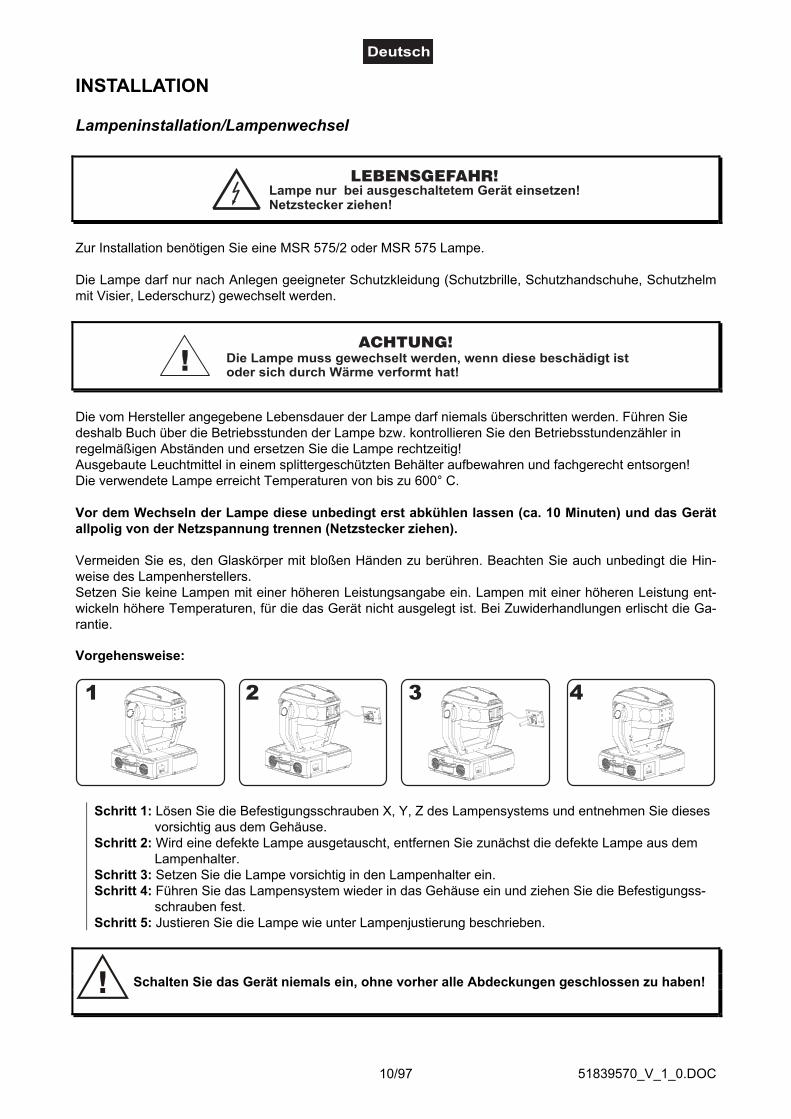
Vorgehensweise:
Schritt 1: Lösen Sie die Befestigungsschrauben X, Y, Z des Lampensystems und entnehmen Sie diesesvorsichtig aus dem Gehäuse.
Schritt 2: Wird eine defekte Lampe ausgetauscht, entfernen Sie zunächst die defekte Lampe aus demLampenhalter.
Schritt 3: Setzen Sie die Lampe vorsichtig in den Lampenhalter ein.Schritt 4: Führen Sie das Lampensystem wieder in das Gehäuse ein und ziehen Sie die Befestigungss-
schrauben fest.Schritt 5: Justieren Sie die Lampe wie unter Lampenjustierung beschrieben.
Schalten Sie das Gerät niemals ein, ohne vorher alle Abdeckungen geschlossen zu haben!

51839570_V_1_0.DOC11/97
Lampenjustierung
Der Lampenhalter des Gerätes wird ab Werk justiert. Da sichdie zu verwendenden Lampen von Hersteller zu Herstellerunterscheiden, kann es u. U. notwendig sein, die Position desLampenhalters nachzujustieren.Zünden Sie die Lampe, öffnen Sie den Shutter, stellen Sie dieDimmerintensität auf 100 % und Sie den Lichtstrahl auf eineebene Oberfläche (Wand). Zentrieren Sie den "Hot Spot" (dasist der hellste Teil des Lichtstrahls) durch Drehen derSchrauben "A, B, C". Drehen Sie immer nur an einerSchraube, um den Hot Spot diagonal über die Projektion zubewegen. Wenn Sie keinen Hot Spot entdecken können,justieren Sie die Lampe so lange, bis das Licht gleichmäßigverteilt ist.Wenn der Hot Spot zu hell erscheint, können Sie dessen
Intensität abschwächen, indem Sie die Lampe näher zum Reflektor hinbewegen. Drehen Sie dazu alle dreiSchrauben "A, B, C" um 45° im Uhrzeigersinn, bis das Licht gleichmäßig verteilt ist.Wenn das Licht am äußeren Rand des Strahls heller erscheint als in der Mitte, befindet sich die Lampe zunah am Reflektor. Bewegen Sie in diesem Fall die Lampe vom Reflektor weg. Drehen Sie dazu alle dreiSchrauben "A, B, C" um 45° gegen den Uhrzeigersinn, bis das Licht gleichmäßig verteilt ist und der Strahlhell genug erscheint.
Einsetzen/Austauschen von Gobos
LEBENSGEFAHR!Gobos nur bei ausgeschaltetem Gerät austauschen
Netzstecker ziehen!
Wenn Sie andere Formen und Muster als die Standard-Gobos verwenden möchten, oder Gobosausgetauscht werden sollen, gehen Sie wie folgt vor:
ACHTUNG!Niemals die Schrauben der rotierenden Gobos lösen,
da ansonsten die Kugellager geöffnet werden!
Entfernen Sie den Sprengring mit einem geeigneten Werkzeug. Entnehmen Sie das Gobo und setzen Siedas neue Gobo ein. Drücken Sie den Sprengring zusammen und setzen Sie ihn vor das Gobo.
Hinweis!Slot In Gobo-System für Gobowechsel ohne Werkzeug!
Einsetzen/Austauschen der Gobos wie oben beschrieben.

51839570_V_1_0.DOC12/97
Projektormontage
LEBENSGEFAHR!Bei der Installation sind insbesondere die Bestimmungen der BGV C1 (vormals VBG 70)und DIN VDE 0711-217 zu beachten! Die Installation darf nur vom autorisierten Fachhan-del ausgeführt werden!
Die Aufhängevorrichtungen des Projektors muss so gebaut und bemessen sein, dass sie 1 Stunde langohne dauernde schädliche Deformierung das 10-fache der Nutzlast aushalten kann.
Die Installation muss immer mit einer zweiten, unabhängigen Aufhängung, z. B. einem geeigneten Fangnetz,erfolgen. Diese zweite Aufhängung muss so beschaffen und angebracht sein, dass im Fehlerfall derHauptaufhängung kein Teil der Installation herabfallen kann.
Während des Auf-, Um- und Abbaus ist der unnötige Aufenthalt im Bereich von Bewegungsflächen, aufBeleuchterbrücken, unter hochgelegenen Arbeitsplätzen sowie an sonstigen Gefahrbereichen verboten.
Der Unternehmer hat dafür zu sorgen, dass sicherheitstechnische und maschinentechnische Einrichtungenvor der ersten Inbetriebnahme und nach wesentlichen Änderungen vor der Wiederinbetriebnahme durchSachverständige geprüft werden.
Der Unternehmer hat dafür zu sorgen, dass sicherheitstechnische und maschinentechnische Einrichtungenmindestens alle vier Jahre durch einen Sachverständigen im Umfang der Abnahmeprüfung geprüft werden.Der Unternehmer hat dafür zu sorgen, dass sicherheitstechnische und maschinentechnische Einrichtungenmindestens einmal jährlich durch einen Sachkundigen geprüft werden.
Vorgehensweise:Der Projektor sollte idealerweise außerhalb des Aufenthaltsbereiches von Personen installiert werden.
WICHTIG! ÜBERKOPFMONTAGE ERFORDERT EIN HOHES MAß AN ERFAHRUNG. Dies beinhaltet (aberbeschränkt sich nicht allein auf) Berechnungen zur Definition der Tragfähigkeit, verwendetes Installations-material und regelmäßige Sicherheitsinspektionen des verwendeten Materials und des Projektors.Versuchen Sie niemals, die Installation selbst vorzunehmen, wenn Sie nicht über eine solche Qualifikationverfügen, sondern beauftragen Sie einen professionellen Installateur. Unsachgemäße Installationen könnenzu Verletzungen und/oder zur Beschädigung von Eigentum führen.
Der Projektor muss außerhalb des Handbereichs von Personen installiert werden.Wenn der Projektor von der Decke oder hochliegenden Trägern etc. abgehängt werden soll, muss immer mitTraversensystemen gearbeitet werden. Der Projektor darf niemals frei schwingend im Raum befestigtwerden.
Achtung: Projektoren können beim Herabstürzen erhebliche Verletzungen verursachen! Wenn Sie Zweifelan der Sicherheit einer möglichen Installationsform haben, installieren Sie den Projektor NICHT!
Vergewissern Sie sich vor der Montage, dass die Montagefläche mindestens die 10-fache Punktbelastungdes Eigengewichtes des Projektors aushalten kann.
Achten Sie bei der Installation des Gerätes bitte darauf, dass sich im Abstandvon mind. 0,5 m keine leicht entflammbaren Materialien (Deko, etc.) befinden.
BRANDGEFAHR!
ACHTUNG!Montieren Sie den Projektor ausschließlich über zwei geeignete Haken. Bitte
beachten Sie auch die Installationshinweise auf der Unterseite derBase. Achten Sie darauf, dass das Gerät sicher befestigt wird.
Vergewissern Sie sich, dass die Verankerung stabil ist.

51839570_V_1_0.DOC13/97
Das Gerät kann direkt auf den Boden gestellt werden oder in jeder möglichen Position im Trussing installiertwerden, ohne seine funktionellen Eigenschaften zu verändern.
Die Projektorbase lässt sich auf zwei verschiedene Arten montieren.
Sichern Sie den Projektor bei Überkopfmontage (Montagehöhe >100 cm) immer mit einem Sicherheitsfang-seil, das mindestens für das 12-fache Gewicht des Gerätes ausgelegt ist. Es dürfen nur Fangseile mitSchnellverschlussgliedern vewendet werden. Hängen Sie das Sicherheitsfangseil an dem dafür vorge-sehenen Loch im Bodenblech ein und führen Sie es über die Traverse bzw. einen sicheren Befestigungs-punkt. Hängen Sie das Ende in dem Schnellverschlussglied ein und ziehen Sie die Sicherungsmutter gutfest.
Der maximale Fallabstand darf 20 cm nicht überschreiten.Ein Sicherungsseil, das einmal der Belastung durch Absturz ausgesetzt war oder beschädigt ist, darf nichtmehr als Sicherungsseil eingesetzt werden.
LEBENSGEFAHR!Vor der ersten Inbetriebnahme muss die Einrichtung durch einen Sachverständigen geprüft werden!
Verschrauben Sie je einen Haken über eine M12 Schraube und Mutter mit den Montagehaltern.Führen Sie die beiden Schnellverschlüsse des ersten Montagehalters in die dafür vorgesehenen Öffnungenan der Geräteunterseite ein. Drehen Sie die Schnellverschlüsse im Uhrzeigersinn bis zum Anschlag fest.Installieren Sie den zweiten Montagehalter.
Anschluss an den DMX-512 Controller / Verbindung Projektor – Projektor

51839570_V_1_0.DOC14/97
Achten Sie darauf, dass die Adern der Datenleitung an keinerStelle miteinander in Kontakt treten. Die Geräte werden
ansonsten nicht bzw. nicht korrekt funktionieren.
Beachten Sie, dass die Startadresse abhängig vom verwendeten Controller ist.Unbedingt Bedienungsanleitung des verwendeten Controllers beachten.
Die Verbindung zwischen Controller und Projektor sowie zwischen den einzelnen Geräten muss mit einemzweipoligen geschirmten Kabel erfolgen. Die Steckverbindung geht über 3-polige XLR-Stecker und-Kupplungen.
Belegung der XLR-Verbindung:
Wenn Sie Controller mit dieser XLR-Belegung verwenden, können Sie den DMX-Ausgang des Controllersdirekt mit dem DMX-Eingang des ersten Gerätes der DMX-Kette verbinden. Sollen DMX-Controller mitanderen XLR-Ausgängen angeschlossen werden, müssen Adapterkabel verwendet werden.
Aufbau einer seriellen DMX-Kette:Schließen Sie den DMX-Ausgang des ersten Gerätes der Kette an den DMX-Eingang des nächsten Gerätesan. Verbinden Sie immer einen Ausgang mit dem Eingang des nächsten Gerätes bis alle Geräte ange-schlossen sind.
Achtung: Am letzten Projektor muss die DMX-Leitung durch einen Abschlusswiderstand abgeschlossenwerden. Dazu wird ein 120 Ω Widerstand in einen XLR-Stecker zwischen Signal (–) und Signal (+) eingelötetund in den DMX-Ausgang am letzten Gerät gesteckt.
Anschluss ans NetzSchließen Sie das Gerät über die beiliegende Netzanschlussleitung ans Netz an.
Die Belegung der Anschlussleitungen ist wie folgt:
Leitung Pin InternationalBraun Außenleiter LBlau Neutralleiter NGelb/Grün Schutzleiter
Der Schutzleiter muss unbedingt angeschlossen werden!Wenn das Gerät direkt an das örtliche Stromnetz angeschlossen wird, muss eine Trennvorrichtung mitmindestens 3 mm Kontaktöffnung an jedem Pol in die festverlegte elektrische Installation eingebaut werden.
Das Gerät darf nur an eine Elektroinstallation angeschlossen werden, die den VDE-BestimmungenDIN VDE 0100 entspricht. Die Hausinstallation muss mit einem Fehlerstromschutzschalter (RCD) mit 30 mABemessungsdifferenzstrom ausgestattet sein.
Lichteffekte dürfen nicht über Dimmerpacks geschaltet werden.

51839570_V_1_0.DOC15/97
BEDIENUNGWenn Sie das Gerät an die Spannungsversorgung angeschlossen haben, nimmt der DJ-HEAD 575 SPOTden Betrieb auf. Während des Reset justieren sich die Motoren aus und das Gerät ist danach betriebsbereit.
Stand Alone-BetriebDer DJ-HEAD 575 SPOT lässt sich im Stand Alone-Betrieb ohne Controller einsetzen.Trennen Sie dazu den DJ-HEAD 575 SPOT vom Controller und rufen Sie das vorprogrammierte Programmauf:
Bitte beachten Sie weitere Hinweise unter Control Board.
DMX-gesteuerter BetriebÜber Ihren DMX-Controller können Sie die einzelnen Geräte individuell ansteuern. Dabei hat jeder DMX-Kanal eine andere Belegung mit verschiedenen Eigenschaften. Die einzelnen DMX-Kanäle und ihreEigenschaften sind unter DMX-Protokoll aufgeführt.
Adressierung des ProjektorsÜber das Control Board können Sie die DMX-Startadresse definieren. Die Startadresse ist der erste Kanal,auf den der Projektor auf Signale vom Controller reagiert.
Wenn Sie die Startadresse z. B. auf 17 definieren belegt der Projektor die Steuerkanäle 17 bis 32.Bitte vergewissern Sie sich, dass sich die Steuerkanäle nicht mit anderen Geräten überlappen, damit der DJ-HEAD 575 SPOT korrekt und unabhängig von anderen Geräten in der DMX-Kette funktioniert.Werden mehrere DJ-HEAD 575 SPOT auf eine Adresse definiert, arbeiten sie synchron.
Vorgehensweise:1. Schalten Sie den DJ-HEAD 575 SPOT ein und warten Sie, bis das Gerät den Setup beendet hat (auf demDisplay blinkt „rSt“).2. Drücken Sie die Mode-Taste, um in das Hauptmenü zu gelangen. Über die Up- und Down-Tasten könnenSie sich durch das Menü bewegen, bis Sie den auf dem Display „A001“ erscheint. Bestätigen Sie mit derEnter-Taste, und der Buchstabe "A" beginnt zu blinken.3. Drücken Sie die Up-/Down-Tasten, um die gewünschte Startadresse auszuwählen.4. Drücken Sie die Enter-Taste zur Bestätigung oder die Mode-Taste um abzubrechen.
Ansteuerung:Nachdem Sie die Startadresse definiert haben, können Sie den DJ-HEAD 575 SPOT über Ihren Controlleransteuern.
Bitte beachten Sie:Über das Display des Gerätes werden die Modi DMX-512 Daten und Lampe angezeigt:
1. Schalten Sie das Gerät ein. Das Gerät prüft, ob DMX-512 Daten empfangen werden oder nicht. WennDaten empfangen werden, erscheint „A001“ mit der definierten Startadresse auf dem Display. Werdenkeine Daten empfangen, blinkt das Display.Die Meldung erscheint-wenn kein 3-poliges XLR-Kabel (DMX Signalkabel vom Controller) in die DMX-Eingangsbuchse desGerätes gesteckt wurde.-wenn der Controller ausgeschaltet oder defekt ist.-das Kabel oder der Stecker defekt ist oder das Signalkabel nicht richtig eingesteckt ist.
Achtung: Am letzten Projektor muss die DMX-Leitung durch einen 120 Ω. Widerstand abgeschlossenwerden damit die Geräte korrekt funktionieren.

51839570_V_1_0.DOC16/97
DMX-Protokoll Steuerkanal 16 Bit-Auflösung (8 Bit-Auflösung)
Steuerkanal 1 (1) - Horizontale Bewegung (Pan) (innerhalb 530°)Wenn Sie den Regler verschieben, bewegen Sie den Kopf horizontal (PAN).Allmähliches Einstellen des Kopfes bei langsamen Schieben des Reglers (0-255, 128-Mitte).Der Kopf kann an jeder gewünschten Einstellung angehalten werden.
Steuerkanal 2 (2)- Vertikale Bewegung (Tilt) (innerhalb 280°)Wenn Sie den Regler verschieben, bewegen Sie den Kopf vertikal (TILT).Allmähliches Einstellen des Kopfes bei langsamen Schieben des Reglers (0-255, 128-Mitte).Der Kopf kann an jeder gewünschten Einstellung angehalten werden.
Steuerkanal 3 - Pan-Bewegung mit 16 Bit-Auflösung
Steuerkanal 4 - Tilt-Bewegung mit 16 Bit-Auflösung
Steuerkanal 5 (3) - Geschwindigkeit Pan-/Tilt-BewegungDecimal Hexad. Percentage S/F Eigenschaft
0 0 00 00 0% 0% S Maximalgeschwindigkeit (Tracking Modus)1 249 01 F9 0% 98% F Abnehmende Geschwindigkeit (Vektor Modus)
250 252 FA FC 98% 99% S Maximalgeschwindigkeit (Tracking Modus), Blackout während Farbeund Gobos wechseln
253 255 FD FF 99% 100% S Maximalgeschwindigkeit (Tracking Modus), Blackout während Pan-/Tilt-Bewegung und Farbgobos wechseln
Steuerkanal 6 (4) - Lampe, Reset, LüfterDecimal Hexad. Percentage S/F Eigenschaft
0 127 00 7F 0% 50% F Lüfter abnehmende Geschwindigkeit128 139 80 8B 50% 55% S Lampe einschalten, Reset, offen140 229 8C E5 55% 90% S Keine Funktion230 239 E6 EF 90% 94% S Lampe wird nach 3 Sekunden abgeschaltet240 255 F0 FF 94% 100% S Keine Funktion
Steuerkanal 7 (5) - Farbrad 1Lineare Farbänderung gemäß der Bewegung des Reglers.Sie können den Farbwechsler an jeder gewünschten Position anhalten.Sie können ebenfalls zwischen zwei Farben anhalten und so zweifarbige Strahlen erzeugen.Zwischen 128 und 190 und zwischen 194 und 255 dreht sich der Farbwechsler ständig - der so genannteRainbow-Effekt entsteht.Decimal Hexad. Percentage S/F Eigenschaft
0 12 00 0C 0% 5% S Offen/weiß13 25 0D 19 5% 10% S Hellblau26 37 1A 25 10% 15% S Rot38 50 26 32 15% 20% S Blau51 63 33 3F 20% 25% S Hellgrün64 76 40 4C 25% 30% S Gelb77 89 4D 59 30% 35% S Magenta90 101 5A 65 35% 40% S Cyan
102 114 66 72 40% 45% S Grün115 127 73 7F 45% 50% S Orange128 190 80 BE 50% 75% F Rainboweffekt vorwärts mit abnehmender Geschwindigkeit191 193 BF C1 75% 76% S Keine Rotation194 255 C2 FF 76% 100% F Rainboweffekt rückwärts mit zunehmender Geschwindigkeit
0 255 00 FF 0% 100% S Farbmakrofunkt. (Kanal 8 zw. 128-255), 64 verschi. Farben mit folg.Reihenf.: weiß, pink, magenta, rot, orange, gelb, grün, cyan, blau, UV

51839570_V_1_0.DOC17/97
Steuerkanal 8 (6) - Farbrad 2Decimal Hexad. Percentage S/F Eigenschaft
0 11 00 0B 0% 4% S Weiß12 23 0C 17 5% 9% S Dunkelrot24 35 18 23 9% 14% S Dunkelblau36 47 24 2F 14% 18% S Pink48 59 30 3B 19% 23% S Cyan60 71 3C 47 24% 28% S Magenta72 83 48 53 28% 33% S Gelb84 95 54 5F 33% 37% S Korrekturfilter 6000 K96 107 60 6B 38% 42% S Korrekturfilter 3200 K
108 119 6C 77 42% 47% S UV-Filter120 127 78 7F 47% 50% S Weiß128 255 80 FF 50% 100% S Aktivierung der Makro-Funktion von Kanal 7
Steuerkanal 9 (7) - PrismenradDecimal Hexad. Percentage S/F Eigenschaft
0 0 00 00 0% 0% S Offen1 63 01 3F 0% 25% F Vorwärtsrotation mit abnehmender Geschwindigkeit
64 64 40 40 25% 25% S Keine Rotation65 127 41 7F 25% 50% F Rückwärtsrotation mit zunehmender Geschwindigkeit
128 135 80 87 50% 53% S Makro 1136 143 88 8F 53% 56% S Makro 2144 151 90 97 56% 59% S Makro 3152 159 98 9F 60% 62% S Makro 4160 167 A0 A7 63% 65% S Makro 5168 175 A8 AF 66% 69% S Makro 6176 183 B0 B7 69% 72% S Makro 7184 191 B8 BF 72% 75% S Makro 8192 199 C0 C7 75% 78% S Makro 9200 207 C8 CF 78% 81% S Makro 10208 215 D0 D7 82% 84% S Makro 11216 223 D8 DF 85% 87% S Makro 12224 231 E0 E7 88% 91% S Makro 13232 239 E8 EF 91% 94% S Makro 14240 247 F0 F7 94% 97% S Makro 15248 255 F8 FF 97% 100% S Makro 16
Steuerkanal 10 (8) - Statisches Goborad, Gobo ShakeDecimal Hexad. Percentage S/F Eigenschaft
0 7 00 07 0% 3% S Offen8 15 08 0F 3% 6% S Gobo 1
16 23 10 17 6% 9% S Gobo 224 31 18 1F 9% 12% S Gobo 332 39 20 27 13% 15% S Gobo 440 47 28 2F 16% 18% S Gobo 548 55 30 37 19% 22% S Gobo 656 63 38 3F 22% 25% S Gobo 764 71 40 47 25% 28% S Gobo 872 79 48 4F 28% 31% S Gobo 980 95 50 5F 31% 37% F Gobo 1 Shake mit variabler Geschwindigkeit96 111 60 6F 38% 44% F Gobo 2 Shake mit variabler Geschwindigkeit
112 127 70 7F 44% 50% F Gobo 3 Shake mit variabler Geschwindigkeit128 143 80 8F 50% 56% F Gobo 4 Shake mit variabler Geschwindigkeit144 159 90 9F 56% 62% F Gobo 5 Shake mit variabler Geschwindigkeit
51839570_V_1_0.DOC18/97
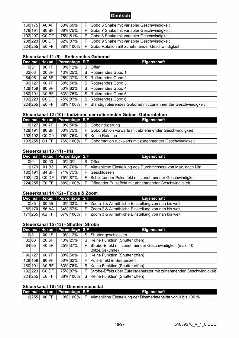
160 175 A0 AF 63% 69% F Gobo 6 Shake mit variabler Geschwindigkeit176 191 B0 BF 69% 75% F Gobo 7 Shake mit variabler Geschwindigkeit192 207 C0 CF 75% 81% F Gobo 8 Shake mit variabler Geschwindigkeit208 223 D0 DF 82% 87% F Gobo 9 Shake mit variabler Geschwindigkeit224 255 E0 FF 88% 100% F Gobo-Rotation mit zunehmender Geschwindigkeit
Steuerkanal 11 (9) - Rotierendes GoboradDecimal Hexad. Percentage S/F Eigenschaft
0 31 00 1F 0% 12% S Offen32 63 20 3F 13% 25% S Rotierendes Gobo 164 95 40 5F 25% 37% S Rotierendes Gobo 296 127 60 7F 38% 50% S Rotierendes Gobo 3
128 159 80 9F 50% 62% S Rotierendes Gobo 4160 191 A0 BF 63% 75% S Rotierendes Gobo 5192 223 C0 DF 75% 87% S Rotierendes Gobo 6224 255 E0 FF 88% 100% F Ständig rotierendes Goborad mit zunehmender Geschwindigkeit
Steuerkanal 12 (10) - Indizieren der rotierenden Gobos, GoborotationDecimal Hexad. Percentage S/F Eigenschaft
0 127 00 7F 0% 50% S Goboindizierung128 191 80 BF 50% 75% F Goborotation vorwärts mit abnehmender Geschwindigkeit192 192 C0 C0 75% 75% S Keine Rotation193 255 C1 FF 76% 100% F Goborotation rückwärts mit zunehmender Geschwindigkeit
Steuerkanal 13 (11) - IrisDecimal Hexad. Percentage S/F Eigenschaft
0 0 00 00 0% 0% S Offen1 179 01 B3 0% 70% F Allmähliche Einstellung des Durchmessers von Max. nach Min.
180 191 B4 BF 71% 75% F Geschlossen192 223 C0 DF 75% 87% F Schließender Pulseffekt mit zunehmender Geschwindigkeit224 255 E0 FF 88% 100% F Öffnender Pulseffekt mit abnehmender Geschwindigkeit
Steuerkanal 14 (12) - Fokus & ZoomDecimal Hexad. Percentage S/F Eigenschaft
0 85 00 55 0% 33% F Zoom 1 & Allmähliche Einstellung von nah bis weit86 170 56 AA 34% 67% F Zoom 2 & Allmähliche Einstellung von nah bis weit
171 255 AB FF 67% 100% F Zoom 3 & Allmähliche Einstellung von nah bis weit
Steuerkanal 15 (13) - Shutter, StrobeDecimal Hexad. Percentage S/F Eigenschaft
0 31 00 1F 0% 12% S Shutter geschlossen32 63 20 3F 13% 25% S Keine Funktion (Shutter offen)64 95 40 5F 25% 37% F Strobe-Effekt mit zunehmender Geschwindigkeit (max. 10
Blitze/Sekunde)96 127 60 7F 38% 50% S Keine Funktion (Shutter offen)
128 159 80 9F 50% 62% F Puls-Effekt in Sequenzen160 191 A0 BF 63% 75% S Keine Funktion (Shutter offen)192 223 C0 DF 75% 87% F Strobe-Effekt über Zufallsgenerator mit zunehmender Geschwindigkeit224 255 E0 FF 88% 100% S Keine Funktion (Shutter offen)
Steuerkanal 16 (14) - DimmerintensitätDecimal Hexad. Percentage S/F Eigenschaft
0 255 00 FF 0% 100% F Allmähliche Einstellung der Dimmerintensität von 0 bis 100 %
51839570_V_1_0.DOC19/97
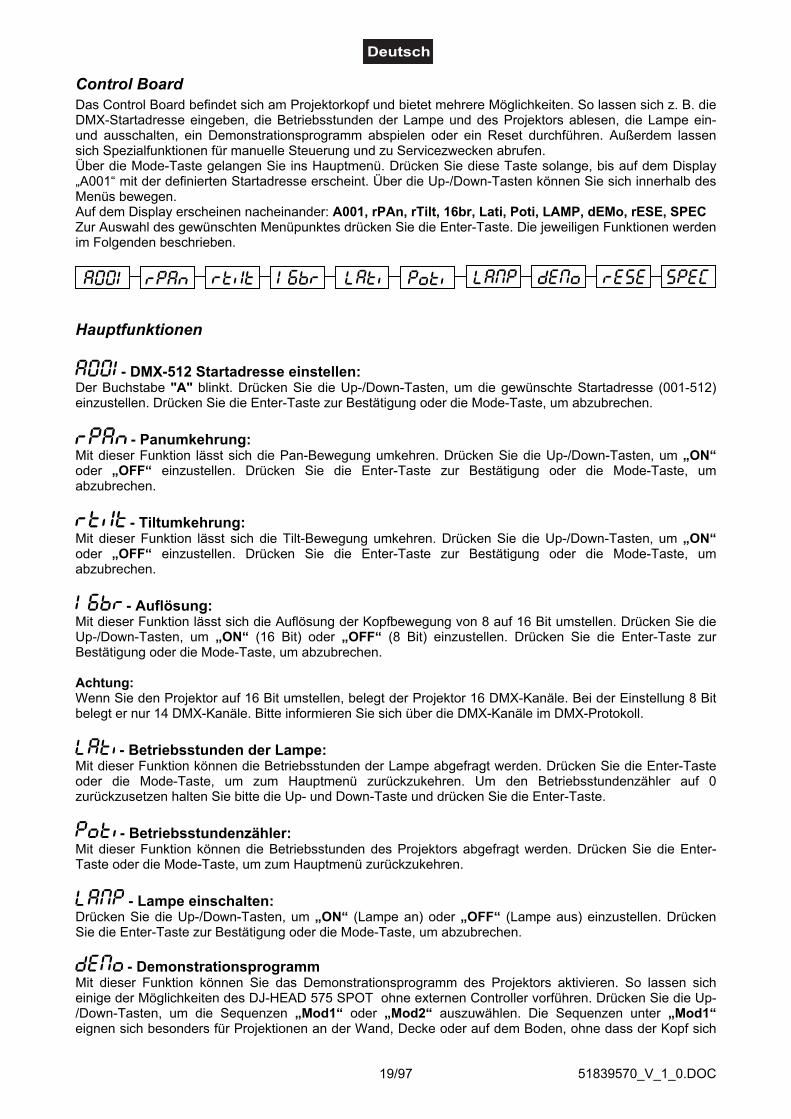
Control BoardDas Control Board befindet sich am Projektorkopf und bietet mehrere Möglichkeiten. So lassen sich z. B. dieDMX-Startadresse eingeben, die Betriebsstunden der Lampe und des Projektors ablesen, die Lampe ein-und ausschalten, ein Demonstrationsprogramm abspielen oder ein Reset durchführen. Außerdem lassensich Spezialfunktionen für manuelle Steuerung und zu Servicezwecken abrufen.Über die Mode-Taste gelangen Sie ins Hauptmenü. Drücken Sie diese Taste solange, bis auf dem Display„A001“ mit der definierten Startadresse erscheint. Über die Up-/Down-Tasten können Sie sich innerhalb desMenüs bewegen.Auf dem Display erscheinen nacheinander: A001, rPAn, rTilt, 16br, Lati, Poti, LAMP, dEMo, rESE, SPECZur Auswahl des gewünschten Menüpunktes drücken Sie die Enter-Taste. Die jeweiligen Funktionen werdenim Folgenden beschrieben.
Hauptfunktionen
- DMX-512 Startadresse einstellen:Der Buchstabe "A" blinkt. Drücken Sie die Up-/Down-Tasten, um die gewünschte Startadresse (001-512)einzustellen. Drücken Sie die Enter-Taste zur Bestätigung oder die Mode-Taste, um abzubrechen.
- Panumkehrung:Mit dieser Funktion lässt sich die Pan-Bewegung umkehren. Drücken Sie die Up-/Down-Tasten, um „ON“oder „OFF“ einzustellen. Drücken Sie die Enter-Taste zur Bestätigung oder die Mode-Taste, umabzubrechen.
- Tiltumkehrung:Mit dieser Funktion lässt sich die Tilt-Bewegung umkehren. Drücken Sie die Up-/Down-Tasten, um „ON“oder „OFF“ einzustellen. Drücken Sie die Enter-Taste zur Bestätigung oder die Mode-Taste, umabzubrechen.
- Auflösung:Mit dieser Funktion lässt sich die Auflösung der Kopfbewegung von 8 auf 16 Bit umstellen. Drücken Sie dieUp-/Down-Tasten, um „ON“ (16 Bit) oder „OFF“ (8 Bit) einzustellen. Drücken Sie die Enter-Taste zurBestätigung oder die Mode-Taste, um abzubrechen.
Achtung:Wenn Sie den Projektor auf 16 Bit umstellen, belegt der Projektor 16 DMX-Kanäle. Bei der Einstellung 8 Bitbelegt er nur 14 DMX-Kanäle. Bitte informieren Sie sich über die DMX-Kanäle im DMX-Protokoll.
- Betriebsstunden der Lampe:Mit dieser Funktion können die Betriebsstunden der Lampe abgefragt werden. Drücken Sie die Enter-Tasteoder die Mode-Taste, um zum Hauptmenü zurückzukehren. Um den Betriebsstundenzähler auf 0zurückzusetzen halten Sie bitte die Up- und Down-Taste und drücken Sie die Enter-Taste.
- Betriebsstundenzähler:Mit dieser Funktion können die Betriebsstunden des Projektors abgefragt werden. Drücken Sie die Enter-Taste oder die Mode-Taste, um zum Hauptmenü zurückzukehren.
- Lampe einschalten:Drücken Sie die Up-/Down-Tasten, um „ON“ (Lampe an) oder „OFF“ (Lampe aus) einzustellen. DrückenSie die Enter-Taste zur Bestätigung oder die Mode-Taste, um abzubrechen.
- DemonstrationsprogrammMit dieser Funktion können Sie das Demonstrationsprogramm des Projektors aktivieren. So lassen sicheinige der Möglichkeiten des DJ-HEAD 575 SPOT ohne externen Controller vorführen. Drücken Sie die Up-/Down-Tasten, um die Sequenzen „Mod1“ oder „Mod2“ auszuwählen. Die Sequenzen unter „Mod1“eignen sich besonders für Projektionen an der Wand, Decke oder auf dem Boden, ohne dass der Kopf sich
51839570_V_1_0.DOC20/97
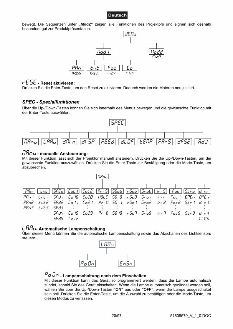
bewegt. Die Sequenzen unter „Mod2“ zeigen alle Funktionen des Projektors und eignen sich deshalbbesonders gut zur Produktpräsentation.
- Reset aktivieren:Drücken Sie die Enter-Taste, um den Reset zu aktivieren. Dadurch werden die Motoren neu justiert.
SPEC - SpezialfunktionenÜber die Up-/Down-Tasten können Sie sich innerhalb des Menüs bewegen und die gewünschte Funktion mitder Enter-Taste auswählen.
- manuelle Ansteuerung:Mit dieser Funktion lässt sich der Projektor manuell ansteuern. Drücken Sie die Up-/Down-Tasten, um diegewünschte Funktion auszuwählen. Drücken Sie die Enter-Taste zur Bestätigung oder die Mode-Taste, umabzubrechen.
- Automatische LampenschaltungÜber dieses Menü können Sie die automatische Lampenschaltung sowie das Abschalten des Lichtsensorssteuern.
- Lampenschaltung nach dem EinschaltenMit dieser Funktion kann das Gerät so programmiert werden, dass die Lampe automatischzündet, sobald Sie das Gerät einschalten. Wenn die Lampe automatisch gezündet werden soll,wählen Sie über die Up-/Down-Tasten "ON" aus oder "OFF", wenn die Lampe ausgeschaltetsein soll. Drücken Sie die Enter-Taste, um die Auswahl zu bestätigen oder die Mode-Taste, umdiesen Modus zu verlassen.

51839570_V_1_0.DOC21/97
- Lampensensor aktivieren/deaktivierenMit dieser Funktion lässt sich der Lampensensor deaktivieren. Drücken Sie die Up-/Down-Tasten, um „ON“ (Lampensensor aktiviert) oder „OFF“ (Lampensensor deaktiviert)einzustellen. Drücken Sie die Enter-Taste zur Bestätigung oder die Mode-Taste, umabzubrechen.Achtung: Die Option "OFF" ist nur für Notfälle gedacht, z. B. wenn der Lichtsensor defektist und Sie auf das Ersatzteil warten. Wenn der Lichtsensor deaktiviert ist, werden dieFehlermeldungen "LAEr, SnEr, HEAt" nicht angezeigt ("HEAt" wird angezeigt, wenn die Lampeinnerhalb von 5 Minuten aus- und wieder eingeschalten wurde). Deshalb wird die Elektronik desGerätes weiterhin versuchen, die Lampe zu zünden, auch wenn die Lampe beschädigt oderüberhaupt keine Lampe vorhanden ist! Bitte beachten Sie, dass bei diesem Vorgang auchelektronische Bauteile beschädigt werden können.
- DMX-Werte:Anzeige der aktuellen DMX-Werte jedes Kanals. Drücken Sie die Up-/Down-Tasten, um den gewünschtenKanal auszuwählen. Drücken Sie die Enter-Taste um den Wert abzulesen oder die Mode-Taste, umabzubrechen.
- Display-Einstellungen:Mit dieser Funktion lassen sich verschiedene Einstellungen für das Display vornehmen:
- Display-Beleuchtung:Mit dieser Funktion können Sie die Display-Beleuchtung zwischen 20 % und 100 % einstellen.Drücken Sie die Up-/Down-Tasten, um den Grad der Displaybeleuchtung einzustellen. DrückenSie die Enter-Taste zur Bestätigung oder die Mode-Taste, um abzubrechen.
- Display-UmkehrungMit dieser Funktion können Sie die Display-Anzeige um 180° drehen. Drücken Sie die Up-/Down-Tasten, um "Normale Anzeige" oder "Umgekehrte Anzeige" einzustellen. Drücken Siedie Enter-Taste zur Bestätigung oder die Mode-Taste, um abzubrechen.
- Display-SchaltungMit dieser Funktion lässt sich einstellen, dass das Gerät das Display nach 2 Minutenautomatisch abschaltet wenn keine Taste mehr gedrückt wurde. Drücken Sie die Up-/Down-Tasten, um „ON“ oder „OFF“ einzustellen. Drücken Sie die Enter-Taste zur Bestätigung oderdie Mode-Taste, um abzubrechen.
- PAN/TILT-Feedback:Mit dieser Funktion lässt sich der Moving-Head wieder in die korrekte Position bringen, nachdem diese z. B.durch einen Schlag etc. extern verändert wurde. Drücken Sie die Up-/Down-Tasten, um „ON“ (Rückkehr zurPosition) oder „OFF“ (ohne Feedback-Funktion) einzustellen. Drücken Sie die Enter-Taste zur Bestätigungoder die Mode-Taste, um abzubrechen.Bitte beachten Sie: Wenn die Feedback-Funktion abgeschaltet wurde, die PAN/TILT-Position durch externeKräfte verändert wurde und die Feedback-Funktion wieder aktiviert wurde kann es passieren, dass dasGerät nicht synchron zu den DMX-Werten arbeitet. In diesem Fall führen Sie bitte einen Reset durch, um dasGerät wieder zu synchronisieren.
51839570_V_1_0.DOC22/97
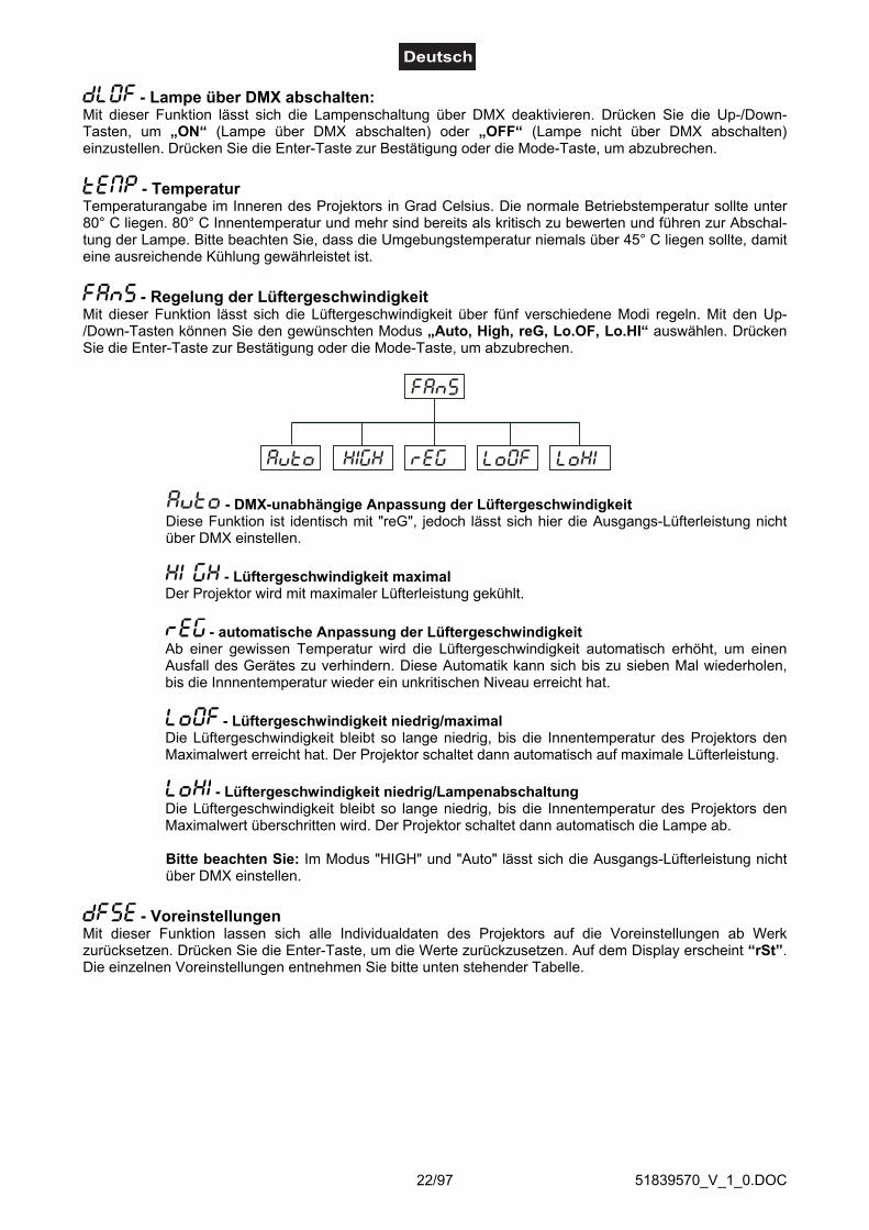
- Lampe über DMX abschalten:Mit dieser Funktion lässt sich die Lampenschaltung über DMX deaktivieren. Drücken Sie die Up-/Down-Tasten, um „ON“ (Lampe über DMX abschalten) oder „OFF“ (Lampe nicht über DMX abschalten)einzustellen. Drücken Sie die Enter-Taste zur Bestätigung oder die Mode-Taste, um abzubrechen.
- TemperaturTemperaturangabe im Inneren des Projektors in Grad Celsius. Die normale Betriebstemperatur sollte unter80° C liegen. 80° C Innentemperatur und mehr sind bereits als kritisch zu bewerten und führen zur Abschal-tung der Lampe. Bitte beachten Sie, dass die Umgebungstemperatur niemals über 45° C liegen sollte, damiteine ausreichende Kühlung gewährleistet ist.
- Regelung der LüftergeschwindigkeitMit dieser Funktion lässt sich die Lüftergeschwindigkeit über fünf verschiedene Modi regeln. Mit den Up-/Down-Tasten können Sie den gewünschten Modus „Auto, High, reG, Lo.OF, Lo.HI“ auswählen. DrückenSie die Enter-Taste zur Bestätigung oder die Mode-Taste, um abzubrechen.
- DMX-unabhängige Anpassung der LüftergeschwindigkeitDiese Funktion ist identisch mit "reG", jedoch lässt sich hier die Ausgangs-Lüfterleistung nichtüber DMX einstellen.
- Lüftergeschwindigkeit maximalDer Projektor wird mit maximaler Lüfterleistung gekühlt.
- automatische Anpassung der LüftergeschwindigkeitAb einer gewissen Temperatur wird die Lüftergeschwindigkeit automatisch erhöht, um einenAusfall des Gerätes zu verhindern. Diese Automatik kann sich bis zu sieben Mal wiederholen,bis die Innnentemperatur wieder ein unkritischen Niveau erreicht hat.
- Lüftergeschwindigkeit niedrig/maximalDie Lüftergeschwindigkeit bleibt so lange niedrig, bis die Innentemperatur des Projektors denMaximalwert erreicht hat. Der Projektor schaltet dann automatisch auf maximale Lüfterleistung.
- Lüftergeschwindigkeit niedrig/LampenabschaltungDie Lüftergeschwindigkeit bleibt so lange niedrig, bis die Innentemperatur des Projektors denMaximalwert überschritten wird. Der Projektor schaltet dann automatisch die Lampe ab.
Bitte beachten Sie: Im Modus "HIGH" und "Auto" lässt sich die Ausgangs-Lüfterleistung nichtüber DMX einstellen.
- VoreinstellungenMit dieser Funktion lassen sich alle Individualdaten des Projektors auf die Voreinstellungen ab Werkzurücksetzen. Drücken Sie die Enter-Taste, um die Werte zurückzusetzen. Auf dem Display erscheint “rSt”.Die einzelnen Voreinstellungen entnehmen Sie bitte unten stehender Tabelle.

51839570_V_1_0.DOC23/97
PAN-Umkehrung
TILT-Umkehrung
Auflösung
AutomatischeLampenabschaltung
AutomatischeDisplayabschaltung
Display-Beleuchtung
Display-Umkehrung
Feedback-Funktion
DMX-Lampenschaltung
Lüfterleistung
Display Vorgabewert(unterlegt)
Eigenschaft
Lampensensoraktivieren/deaktiv.
- Einstellung der Ausgangspositionen:Mit dieser Funktion lassen sich das Farb-, Gobo- und Prismenrad auf die korrekten Ausgangspositionenkalibrieren. Drücken Sie die Up-/Down-Tasten, um sich im Menü zu bewegen. Auf dem Display erscheinenvon Schritt zu Schritt die Folgenden Funktionen: „PAn, Tilt, SPEd, Col1, Col2, PriS, SGob, rGob, Grot,IriS, Foc, Stro, dimr, FCAL“ über die Sie den Projektor auf die gewünschte Position (0-255) einstellenkönnen, bevor kalibriert wird. Sobald Sie die Positionen eingegeben haben, wählen Sie die Letzte Funktion„FCAL“, und das Gerät wird kalibriert.
1. Kalibrieren über das Control BoardDrücken Sie die Enter-Taste und auf dem Display erscheint durch Drücken der Up-/Down-Tasten: „Colo,EFEC, rGob, Grot“ für sehr weiche Funktionskalibrierung. Wählen Sie eine dieser Funktionen über dieEnter-Taste um den richtigen Wert zwischen 0 und 255 einzugstellen. Drücken Sie die Enter-Taste zurBestätigung oder die Mode-Taste um abzubrechen. Diese Vorgehensweise lässt sich für jedenKalibrierungsparameter wiederholen. Sobald die Kalibrierungseinstellungen vorgenommen sind, muss dieFunktion „ArES“ gewählt werden, um die eingestellten Werte in das EEPROM zu übertragen und einenReset auszuführen. Sobald der Reset abgeschlossen ist, erscheint auf dem Display „FCAL". Drücken Sie dieEnter-Taste, um die Kalibrierung zu wiederholen oder die Mode-Taste, um zum „AdJ“ Menü zurückzukehren.2. Kalibrierung über den externen ControllerDrücken Sie die Enter-Taste und auf dem Display erscheint durch Drücken der Up-/Down-Tasten: „Col1,Col2, PriS, SGob, rGob, Grot“ für sehr weiche Funktionskalibrierung. Wählen Sie eine dieser Funktionenüber die Enter-Taste aus. Jetzt können Sie die verschiedenen Räder über Ihren Controller kalibrieren. DasKalibrierungsprotokoll finden Sie unten stehend.

51839570_V_1_0.DOC24/97
DMX Kalibrierungsprotokoll:
Nachdem Sie die benötigten Funktionen kalibriert haben und mit der Enter-Taste bestätigt haben, muss dieFunktion „ArES“ gewählt werden, um die eingestellten Werte in das EEPROM zu übertragen und einenReset auszuführen.
FehlermeldungenWenn Sie das Gerät einschalten, wird zuerst ein Reset durchgeführt. Wenn auf dem Display eineFehlermeldung erscheint, gibt es Fehler an einem oder mehreren Kanälen. Die Fehlermeldung stehtfür den entsprechenden Kanal mit einem Testsensor für die korrekte Position.Wenn auf dem Display z. B. “C2Er” erscheint, bedeutet dies einen Fehler an Farbrad 2. Gibt esgleichzeitig einen Fehler an mehreren Kanälen, blinken die Fehlermeldungen 5 Mal im Display,danach führt das Gerät einen Reset durch. Wenn die Fehlermeldungen nach dem Reset noch dreimalerscheinen, wird das Gerät prüfen ob mehr als 3 Fehler vorliegen. Wenn 3 Fehlermeldungen odermehr vorliegen, arbeitet das Gerät nicht mehr fehlerfrei, wenn weniger als 3 Fehlermeldungenvorliegen arbeiten nur die Kanäle mit den Fehler nicht fehlerfrei.
Die entsprechende Fehlermeldung erscheint, wenn nach dem Reset magnetisch-indizierte Fehlfunktionen andem entsprechenden Kanalfeature vorliegen (Photodiode defekt oder der Magnet fehlt) oder derSteppermotor defekt ist (oder dessen Treiber auf der Hauptplatine). Dabei befindet sich das entsprechendeKanalfeature nach dem Reset nicht in der Vorgabeposition.Die verschiedenen Fehlermeldungen sind:
Diese Fehlermeldung erscheint, wenn Sie versuchen, die Lampe zu zünden bevor die 5 Minuten Abkühlzeitverstrichen sind. Die Meldung erscheint, wenn die Lampe nach 20 Sekunden nicht gezündet hat. Der DJ-HEAD 575 SPOT speichert die Information wenn Sie vorzeitig versuchen, die Lampe zu zünden, und zündetdie Lampe automatisch nachdem die 5 Minuten verstrichen sind.Achtung: Bitte beachten Sie, dass diese Funktion abgeschaltet ist, wenn der Lichtsensor der Lampe(Funktion "EnSn") deaktiviert ist.
Nach 7 fehlerhaften Versuchen, die Lampe zu zünden, erscheint auf dem Display „LAEr“. Dies bedeutet,dass die Lampe beschädigt ist oder gar keine Lampe installiert ist oder ein interner Fehler vorliegt.Bitte setzen Sie eine Lampe ein oder ersetzen Sie die defekte Lampe. Sollte ein interner Fehler vorliegen,setzen Sie sich bitte mit Ihrem Fachhändler in Verbindung.Achtung: Bitte beachten Sie, dass diese Funktion abgeschaltet ist, wenn der Lichtsensor der Lampe(Funktion "EnSn") deaktiviert ist.
Diese Fehlermeldung erscheint, wenn die Kommunikation zwischen Hauptplatine und Control Board gestörtist.
Fehler an Farbrad 1. Diese Fehlermeldung erscheint, wenn nach dem Reset die magnetisch-indizierteFehlfunktionen vorliegen (Photodiode defekt oder der Magnet fehlt) oder der Steppermotor defekt ist (oderdessen Treiber auf der Hauptplatine). Dabei befindet sich das Farbrad nach dem Reset nicht in derVorgabeposition.
DMX Channel 1 2 3 4 5 6 7 8
COL.1 COL.2 SGOB RGOB GROT - COLOURS 1 COLOURS 2CALIBRATION
0 - 255CALIBRATION
0 - 255CALIBRATION
0 - 255CALIBRATION
0 - 255CALIBRATION
0 - 255-
STANDARD PROTOCOL
STANDARD PROTOCOL
DMX Channel 9 10 11 12 13 14 15 16
PRISMSTATIC GOBOS
ROTATING GOBOS
GOBO ROTATION
IRIS FOCUS STROBE DIMMER
STANDARD PROTOCOL
STANDARD PROTOCOL
STANDARD PROTOCOL
STANDARD PROTOCOL
STANDARD PROTOCOL
STANDARD PROTOCOL
STANDARD PROTOCOL
STANDARD PROTOCOL
Function
SMOOTH MICROSTEP MOVEMENT
Function

51839570_V_1_0.DOC25/97
Fehler an Farbrad 2. Diese Fehlermeldung erscheint, wenn nach dem Reset die magnetisch-indizierteFehlfunktionen vorliegen (Photodiode defekt oder der Magnet fehlt) oder der Steppermotor defekt ist (oderdessen Treiber auf der Hauptplatine). Dabei befindet sich das Farbrad nach dem Reset nicht in derVorgabeposition.
Fehler am rotierenden Goborad. Diese Fehlermeldung erscheint, wenn nach dem Reset magnetisch-indizierte Fehlfunktionen vorliegen (Photodiode defekt oder der Magnet fehlt) oder der Steppermotor defektist (oder dessen Treiber auf der Hauptplatine). Dabei befindet sich das rotierenden Goborad nach demReset nicht in der Vorgabeposition.
Indexfehler am rotierenden Gobo. Diese Fehlermeldung erscheint, wenn nach dem Reset magnetisch-indizierte Fehlfunktionen vorliegen (Photodiode defekt oder der Magnet fehlt) oder der Steppermotor defektist (oder dessen Treiber auf der Hauptplatine). Dabei befindet sich das rotierende Gobo nach dem Resetnicht in der Vorgabeposition.
Fehler am statischen Goborad. Diese Fehlermeldung erscheint, wenn nach dem Reset magnetisch-indizierteFehlfunktionen vorliegen (Photodiode defekt oder der Magnet fehlt) oder der Steppermotor defekt ist (oderdessen Treiber auf der Hauptplatine). Dabei befindet sich das Goborad nach dem Reset nicht in derVorgabeposition.
Fehler am Prismenrad. Diese Fehlermeldung erscheint, wenn nach dem Reset magnetisch-indizierteFehlfunktionen vorliegen (Photodiode defekt oder der Magnet fehlt) oder der Steppermotor defekt ist (oderdessen Treiber auf der Hauptplatine). Dabei befindet sich das Prismenrad nach dem Reset nicht in derVorgabeposition.
Diese Fehlermeldung bedeutet, dass das Gerät überhitzt ist (was bei 45° C oder mehr der Fall sein kann)und das Relais die Lampe abgeschaltet hat. Diese Meldung bleibt solange im Display, bis die Temperatursich auf ein unkritisches Niveau gesenkt hat. Danach erscheint „HEAt“, um anzuzeigen, dass die Lampenoch zu heiß ist.
Diese Fehlermeldung erscheint, wenn die Photodiode defekt ist. Bitte setzen Sie sich mit ihrem Fachhändlerin Verbindung.Achtung: Bitte beachten Sie, dass diese Funktion abgeschaltet ist, wenn der Lichtsensor der Lampe(Funktion "EnSn") deaktiviert ist.
Diese Fehlermeldung erscheint, wenn das Gerät kurzzeitig vom Netz getrennt wurde.
Fehler an der PAN-Bewegung der Aufhängung. Diese Fehlermeldung erscheint, wenn nach dem Resetmagnetisch-indizierte Fehlfunktionen an der Aufhängung vorliegen (Photodiode defekt oder der Magnetfehlt) oder der Steppermotor defekt ist (oder dessen Treiber auf der Hauptplatine). Dabei befindet sich dieAufhängung nach dem Reset nicht in der Vorgabeposition.
Fehler an der TILT-Bewegung des Projektorkopfes. Diese Fehlermeldung erscheint, wenn nach dem Resetmagnetisch-indizierte Fehlfunktionen an dem Projektorkopf vorliegen (Photodiode defekt oder der Magnetfehlt) oder der Steppermotor defekt ist (oder dessen Treiber auf der Hauptplatine). Dabei befindet sich derProjektorkopf nach dem Reset nicht in der Vorgabeposition.
Diese Fehlermeldung erscheint, wenn die Netzversorgung nicht auf 50 oder 60 Hz lautet.

51839570_V_1_0.DOC26/97
REINIGUNG UND WARTUNGDer Unternehmer hat dafür zu sorgen, dass sicherheitstechnische und maschinentechnische Einrichtungenmindestens alle vier Jahre durch einen Sachverständigen im Umfang der Abnahmeprüfung geprüft werden.Der Unternehmer hat dafür zu sorgen, dass sicherheitstechnische und maschinentechnische Einrichtungenmindestens einmal jährlich durch einen Sachkundigen geprüft werden.Dabei muss unter anderem auf folgende Punkte besonders geachtet werden:1) Alle Schrauben, mit denen das Gerät oder Geräteteile montiert sind, müssen fest sitzen und dürfen nicht
korrodiert sein.2) An Gehäuse, Befestigungen und Montageort (Decke, Abhängung, Traverse) dürfen keine Verformungen
sichtbar sein.3) Mechanisch bewegte Teile wie Achsen, Ösen u. Ä. dürfen keinerlei Verschleißspuren zeigen (z.B.
Materialabrieb oder Beschädigungen) und dürfen sich nicht unwuchtig drehen.4) Die elektrischen Anschlussleitungen dürfen keinerlei Beschädigungen, Materialalterung (z.B. poröse
Leitungen) oder Ablagerungen aufweisen. Weitere, auf den jeweiligen Einsatzort und die Nutzungabgestimmte Vorschriften werden vom sachkundigen Installateur beachtet und Sicherheitsmängelbehoben.
Vor Wartungsarbeiten unbedingt allpolig vom Netz trennen!
LEBENSGEFAHR!
Das Gerät sollte regelmäßig von Verunreinigungen wie Staub usw. gereinigt werden. Verwenden Sie zurReinigung ein fusselfreies, angefeuchtetes Tuch. Auf keinen Fall Alkohol oder irgendwelche Lösungsmittelzur Reinigung verwenden!
Die Linse muss gewechselt werden, wenn diese sichtbar beschädigt ist,so dass ihre Wirksamkeit beeinträchtigt ist, z. B. durch Sprünge oder tiefe Kratzer!
ACHTUNG!
Die Objektivlinse sollte wöchentlich gereinigt werden, da sich sehr schnell Nebelfluidrückstände absetzen,die die Leuchtkraft des Gerätes erheblich reduzieren. Den Lüfter monatlich reinigen.
Schalten Sie das Gerät niemals ein, ohne vorher alle Abdeckungen geschlossen zu haben!
Die Gobos können mit einer weichen Bürste gereinigt werden. Reinigen Sie das Innere des Projektorsmindestens einmal im Jahr mit einem Staubsauger oder einer Luftbürste.
Die dichroitischen Farbfilter, das Goborad und die Innenlinsen sollten monatlich gereinigt werden.
Damit die Lager der rotierenden Teile gut funktionieren, müssen sie ca. alle 6 Monate geschmiert werden.Zum Ölen ist eine Spritze mit einer feinen Nadel zu benutzen. Die Ölmenge darf nicht übermäßig sein, um zuvermeiden, dass das Öl während des Rotierens ausläuft.
Im Geräteinneren befinden sich außer der Lampe und der Sicherung keine zu wartenden Teile. Wartungs-und Servicearbeiten sind ausschließlich dem autorisierten Fachhandel vorbehalten!
Bitte beachten Sie auch die Hinweise unter "Lampeninstallation/Lampenwechsel".

51839570_V_1_0.DOC27/97
SicherungswechselBeim Ausfall der Lampe kann die Feinsicherung des Gerätes durchbrennen. Wenn die Feinsicherung desGerätes defekt ist, darf diese nur durch eine Sicherung gleichen Typs ersetzt werden.Vor dem Sicherungswechsel ist das Gerät allpolig von der Netzspannung zu trennen (Netzsteckerziehen).
Vorgehensweise:
Schritt 1: Öffnen Sie den Sicherungshalter an der Geräterückseite mit einem passendenSchraubendreher.
Schritt 2: Entfernen Sie die defekte Sicherung aus dem Sicherungshalter.Schritt 3: Setzen Sie die neue Sicherung in den Sicherungshalter ein.Schritt 4: Setzen Sie den Sicherungshalter wieder im Gehäuse ein.
Sollten einmal Ersatzteile benötigt werden, verwenden Sie bitte nur Originalersatzteile.Wenn die Anschlussleitung dieses Gerätes beschädigt wird, muss sie durch eine besondere Anschluss-leitung ersetzt werden, die von Ihrem Fachhändler erhältlich ist.Sollten Sie noch weitere Fragen haben, steht Ihnen Ihr Fachhändler jederzeit gerne zur Verfügung.
TECHNISCHE DATENSpannungsversorgung: 230 V AC, 50 Hz ~Gesamtanschlusswert: 1000 WDMX-Steuerkanäle:16DMX 512-Anschluss: 3-pol. XLRBlitzrate: 10 HzAnzahl der Farben:Farbrad 1: 9 dichroitische + weißFarbrad 2: 6 dichroitische, 2 Korrekturfilter, UV-Filter +
weiß, 64 mögliche FarbmischungenAnzahl der Gobos:Goborad 1: 9 statische Metallgobos + offenGoborad 2: 2 rotierende Metallgobos, 4 rotierende
Multicolor-Dichrogobos + offenAußendurchmesser der Gobos: 27 mmImagedurchmesser der Gobos: 23 mmLänge der Grundfläche (mit Griffen): 500 mmBreite: 475 mmHöhe (Kopf horizontal): 560 mmGewicht (netto): 35,5 kgMaximale Umgebungstemperatur Ta: 45 °CMaximale Leuchtentemperatur im Beharrungszustand TB: 70 °CMindestabstand zu enflammbaren Oberflächen: 0,5 mMindestabstand zum angestrahlten Objekt: 0,5 mSicherung: T 8 A, 250 VZubehör:GE CSR575/2 SE 95V/575W GX-9,5 1000h Best.-Nr. 89107000PHILIPS MSR575/2 95V/575W GX-9,5 1000h Best.-Nr. 89107015SYLVANIA BA575/2 SE NHR 95V/575W GX-9,5 Best.-Nr. 89107020OSRAM HSR 575/72 95V/575W GX-9,5 1000h Best.-Nr. 89107210FUTURELIGHT CP-240 Controller Best.-Nr. 51834265FUTURELIGHT CP-256/64 Controller 16bit Best.-Nr. 51834288FUTURELIGHT CP-512/64 Controller 16bit Best.-Nr. 51834295Wizard-512 USB DMX-Software + Interface Best.-Nr. 51860102Wizard-1024 USB DMX-Software + Interface Best.-Nr. 51860110FUTURELIGHT DES-3 Abschlusstecker 3-pol Best.-Nr. 51834001
Bitte beachten Sie: Technische Änderungen ohne vorherige Ankündigung und Irrtum vorbehalten.26.04.2006 ©

51839570_V_1_0.DOC28/97
USER MANUAL
DJ-HEAD 575 SPOTPro-Head-Spot
CAUTION!Keep this device away from rain and moisture!Unplug mains lead before opening the housing!
For your own safety, please read this user manual carefully before you initial start-up.
Every person involved with the installation, operation and maintenance of this device has to- be qualified- follow the instructions of this manual- consider this manual to be part of the total product- keep this manual for the entire service life of the product- pass this manual on to every further owner or user of the product- download the latest version of the user manual from the Internet
INTRODUCTIONThank you for having chosen a FUTURELIGHT DJ-HEAD 575 SPOT. You will see you have acquired apowerful and versatile device.
Unpack your DJ-HEAD 575 SPOT.
Delivery includes
1 Device1 User manual1 Cable MC-50, 5m, black, XLR m/f,balanced 3022050N2 Mounting holder

51839570_V_1_0.DOC29/97
SAFETY INSTRUCTIONS
CAUTION!Be careful with your operations. With a dangerous voltage you can suffer a dangerouselectric shock when touching the wires!
This device has left our premises in absolutely perfect condition. In order to maintain this condition and toensure a safe operation, it is absolutely necessary for the user to follow the safety instructions and warningnotes written in this user manual.
Important:Damages caused by the disregard of this user manual are not subject to warranty. The dealerwill not accept liability for any resulting defects or problems.
If the device has been exposed to drastic temperature fluctuation (e.g. after transportation), do not switch iton immediately. The arising condensation water might damage your device. Leave the device switched offuntil it has reached room temperature.
Please make sure that there are no obvious transport damages. Should you notice any damages on the A/Cconnection cable or on the casing, do not take the device into operation and immediately consult your localdealer.
This device falls under protection-class I. The power plug must only be plugged into a protection class Ioutlet. The voltage and frequency must exactly be the same as stated on the device. Wrong voltages orpower outlets can lead to the destruction of the device and to mortal electrical shock.
Always plug in the power plug last. The power plug must always be inserted without force. Make sure thatthe plug is tightly connected with the outlet.
Never let the power-cord come into contact with other cables! Handle the power-cord and all connectionswith the mains with particular caution! Never touch them with wet hands, as this could lead to mortalelectrical shock.
Never modify, bend, strain mechanically, put pressure on, pull or heat up the power cord. Never operate nextto sources of heat or cold. Disregard can lead to power cord damages, fire or mortal electrical shock.
The cable insert or the female part in the device must never be strained. There must always be sufficientcable to the device. Otherwise, the cable may be damaged which may lead to mortal damage.
Make sure that the power-cord is never crimped or damaged by sharp edges. Check the device and thepower-cord from time to time.
If extension cords are used, make sure that the core diameter is sufficient for the required powerconsumption of the device. All warnings concerning the power cords are also valid for possible extensioncords.
Always disconnect from the mains, when the device is not in use or before cleaning it. Only handle thepower-cord by the plug. Never pull out the plug by tugging the power-cord. Otherwise, the cable or plug canbe damaged leading to mortal electrical shock. If the power plug or the power switch is not accessible, thedevice must be disconnected via the mains.
If the power plug or the device is dusty, the device must be taken out of operation, disconnected and then becleaned with a dry cloth. Dust can reduce the insulation which may lead to mortal electrical shock. Moresevere dirt in and at the device should only be removed by a specialist.
There must never enter any liquid into power outlets, extension cords or any holes in the housing of thedevice. If you suppose that also a minimal amount of liquid may have entered the device, it must immediatelybe disconnected. This is also valid, if the device was exposed to high humidity. Also if the device is still
51839570_V_1_0.DOC30/97
running, the device must be checked by a specialist if the liquid has reduced any insulation. Reducedinsulation can cause mortal electrical shock.
There must never be any objects entering into the device. This is especially valid for metal parts. If any metalparts like staples or coarse metal chips enter into the device, the device must be taken out of operation anddisconnected immediately. Malfunction or short-circuits caused by metal parts may cause mortal injuries.
During the initial start-up some smoke or smell may arise. This is a normal process and does not necessarilymean that the device is defective.
Danger of burning! Never install the device on a highly flammable surfaces (e.g. fair carpet)!Caution: During the operation, the housing becomes very hot.
Do not switch the device on and off in short intervals as this would reduce the lamp’s life.
HEALTH HAZARD!Never look directly into the light source, as sensitive persons may suffer anepileptic shock (especially meant for epileptics)!
Keep away children and amateurs!Never leave this device running unattended.
OPERATING DETERMINATIONSThis device is a moving-head spot for creating decorative effects. This product is only allowed to be operatedwith an alternating current of 230 V, 50 Hz and was designed for indoor use only.
This device is designed for professional use, e.g. on stages, in discotheques, theatres etc.
Lighting effects are not designed for permanent operation. Consistent operation breaks will ensure that thedevice will serve you for a long time without defects.
Do not shake the device. Avoid brute force when installing or operating the device.
Never lift the fixture by holding it at the projector-head, as the mechanics may be damaged. Always hold thefixture at the transport handles.
When choosing the installation-spot, please make sure that the device is not exposed to extreme heat,moisture or dust. There should not be any cables lying around. Please make sure that the unit cannot betouched or bumped. You endanger your own and the safety of others!
This device must never be operated or stockpiled in sourroundings where splash water, rain, moisture or fogmay harm the device. Moisture or very high humidity can reduce the insulation and lead to mortal electricalshocks. When using smoke machines, make sure that the device is never exposed to the direct smoke jetand is installed in a distance of 0.5 meters between smoke machine and device. The room must only besaturated with an amount of smoke that the visibility will always be more than 10 meters.The ambient temperature must always be between -5° C and +45° C. Keep away from direct insulation(particularly in cars) and heaters.
The relative humidity must not exceed 50 % with an ambient temperature of 45° C.This device must only be operated in an altitude between -20 and 2000 m over NN.
Never use the device during thunderstorms. Over voltage could destroy the device. Always disconnect thedevice during thunderstorms.
The symbol - - -m determines the minimum distance from lighted objects. The minimum distancebetween light-output and the illuminated surface must be more than this value.

51839570_V_1_0.DOC31/97
The device must only be installed on a non-flammable surface. In order to safeguard sufficient ventilation,leave 50 cm of free space around the device. Please note that heat-sensitive objects may be deformed ordamaged by the emitted heat.
Make sure that the area below the installation place is blocked when rigging, derigging or servicing thefixture.For overhead use (mounting height >100 cm), always fix the fixture with an appropriate safety-rope. Fix thesafety-rope at the correct fixation points only. The safety-rope must never be fixed at the transport handles!
Only operate the fixture after having checked that the housing is firmly closed and all screws are tightlyfastened.The lamp must never be ignited if the objective-lens or any housing-cover is open, as discharge lamps mayexplose and emit a high ultraviolet radiation, which may cause burns.
The maximum ambient temperature Ta = 45° C must never be exceeded.
Operate the device only after having familiarized with its functions. Do not permit operation by persons notqualified for operating the device. Most damages are the result of unprofessional operation!
Please use the original packaging if the device is to be transported.Please consider that unauthorized modifications on the device are forbidden due to safety reasons!Never remove the serial barcode from the device as this would make the guarantee void.
If this device will be operated in any way different to the one described in this manual, the product may sufferdamages and the guarantee becomes void. Furthermore, any other operation may lead to dangers like short-circuit, burns, electric shock, lamp explosion, crash etc.
DESCRIPTION OF THE DEVICE
FeaturesPowerful DJ-Moving-head• Colour-system: 2 colour-wheels• Colour-wheel 1 with 9 different, dichroic colour-filtres and white• Colour-wheel 2 with 6 different, dichroic colour-filtres and white and additionally with correction-filters 3,200K and 6,000 K and UV-filter• Via the two correction-filters, up to 64 different colours and semi-colours can be created• Rainbow-effect in both directions• Gobo-wheel 1 with 9 static metal-gobos and open• With gobo-shake function for static gobos• Gobo-wheel 2 with 2 rotating metal-gobos, 4 multicolor-dichro-gobos and open• The rotating gobos can be interchanged• Via the combination between dichro-gobos and color-wheel or multicolor-dichro-gobo even more colour-combinations possible• High-speed rotating 3-facet prism• Remotely controllable motorized focus• Combined shutter/dimmer unit allowing very smooth dimming and strobo effect 1-10 flash per sec.• Remotely switching of the lamp• Macro-function for rotating gobos/rotating prism combinations• Black-out while Head moving or gobo/colour/prism changing• Remotely controllable speed of Pan/Tilt movement for easy programming• Remote reset function• Silent fans cooling; remotely controllable speed of fans• 16 DMX-channels - 16 bit Pan/Tilt movement resolution• 14 DMX-channels - 8 bit Pan/Tilt movement resolution• Pan-movement range 530°• Tilt-movement range 280°• Motorized multi-step-zoom with three different apertures (15°, 18° and 22°)• Steplessly adjustable iris• Control-Board with 4-digit display for adjusting the DMX-starting address• For MSR 575/2 or MSR 575 lamp• DMX-control via every standard DMX-controller

51839570_V_1_0.DOC32/97
Overview
(1) Projector head
(2) Lens
(3) Yoke
(4) Base
(5) Carrying handle
(6) Ventilation fan
(7) Power switch
(8) DMX-In socket
(9) DMX-Out socket
(10) Power supply/
Fuseholder
(11) Lamp system
(12) Control LED
(13) Display
(14) Mode-button
(15) Enter-button
(16) Down-button
(17) Up-button
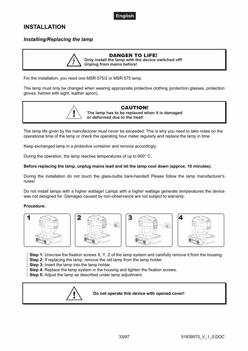
51839570_V_1_0.DOC33/97
INSTALLATION
Installing/Replacing the lamp
DANGER TO LIFE!Only install the lamp with the device switched off!Unplug from mains before!
For the installation, you need one MSR 575/2 or MSR 575 lamp.
The lamp must only be changed when wearing appropriate protective clothing (protection glasses, protectiongloves, helmet with sight, leather apron).
The lamp has to be replaced when it is damagedor deformed due to the heat!
CAUTION!
The lamp life given by the manufacturer must never be exceeded. This is why you need to take notes on theoperational time of the lamp or check the operating hour meter regularly and replace the lamp in time.
Keep exchanged lamp in a protective container and remove accordingly.
During the operation, the lamp reaches temperatures of up to 600° C.
Before replacing the lamp, unplug mains lead and let the lamp cool down (approx. 10 minutes).
During the installation do not touch the glass-bulbs bare-handed! Please follow the lamp manufacturer'snotes!
Do not install lamps with a higher wattage! Lamps with a higher wattage generate temperatures the devicewas not designed for. Damages caused by non-observance are not subject to warranty.
Procedure:
Step 1: Unscrew the fixation screws X, Y, Z of the lamp system and carefully remove it from the housing.Step 2: If replacing the lamp, remove the old lamp from the lamp holder.Step 3: Insert the lamp into the lamp holder.Step 4: Replace the lamp system in the housing and tighten the fixation screws.Step 5: Adjust the lamp as described under lamp adjustment.
Do not operate this device with opened cover!

51839570_V_1_0.DOC34/97
Lamp adjustment
The lampholder is aligned at the factory. Due to differencesbetween lamps, fine adjustment may improve light performance.
Strike the lamp, open the shutter, set the dimmer intensity onto100 % and direct the light towards a flat surface (wall). Center thehot-spot (the brightest part of the beam) using the 3 adjustmentscrews "A, B, C”. Turn one screw at a time to drag the hot-spotdiagonally across the projected image. If you cannot detect a hot-spot, adjust the lamp until the light is even.
To reduce a hot-spot, pull the lamp in by turning all three screws"A, B, C” clockwise ¼-turn at a time until the light is evenlydistributed.
If the light is brighter around the edge than it is in the center, or if light output is low, the lamp is too far backin the reflector. "Push” the lamp out by turning the screws "A, B, C” counterclockwise ¼-turn at a time thelight is bright and evenly distributed.
Inserting/Exchanging gobos
DANGER!Install the gobos with the device switched off only.
Unplug from mains before!
If you wish to use other forms and patterns as the standard-gobos, or if gobos are to be exchanged, pleasefollow the instructions below:
CAUTION!Never unscrew the screws of the rotating goboas the ball bearing will otherwise be opened!
Remove the fixation-ring with an appropriate tool. Remove the gobo and insert the new gobo. Press thefixation-ring together and insert it in front of the gobo.
Please note!Slot-in gobo-system for exchanging gobos without tools!
Inserting/Exchanging gobos as described above.

51839570_V_1_0.DOC35/97
Rigging
DANGER TO LIFE!Please consider the EN 60598-2-17 and the respective national norms during theinstallation! The installation must only be carried out by an authorized dealer!
The installation of the projector has to be built and constructed in a way that it can hold 10 times the weightfor 1 hour without any harming deformation.
The installation must always be secured with a secondary safety attachment, e.g. an appropriate catch net.This secondary safety attachment must be constructed in a way that no part of the installation can fall downif the main attachment fails.
When rigging, derigging or servicing the fixture staying in the area below the installation place, on bridges,under high working places and other endangered areas is forbidden.
The operator has to make sure that safety-relating and machine-technical installations are approved by anexpert before taking into operation for the first time and after changes before taking into operation anothertime.
The operator has to make sure that safety-relating and machine-technical installations are approved by anexpert after every four year in the course of an acceptance test.
The operator has to make sure that safety-relating and machine-technical installations are approved by askilled person once a year.
Procedure:The projector should be installed outside areas where persons may walk by or be seated.
IMPORTANT! OVERHEAD RIGGING REQUIRES EXTENSIVE EXPERIENCE, including (but not limited to)calculating working load limits, installation material being used, and periodic safety inspection of allinstallation material and the projector. If you lack these qualifications, do not attempt the installation yourself,but instead use a professional structural rigger. Improper installation can result in bodily injury and.ordamage to property.
The projector has to be installed out of the reach of people.If the projector shall be lowered from the ceiling or high joists, professional trussing systems have to beused. The projector must never be fixed swinging freely in the room.
Caution: Projectors may cause severe injuries when crashing down! If you have doubts concerning thesafety of a possible installation, do NOT install the projector!
Before rigging make sure that the installation area can hold a minimum point load of 10 times the projector'sweight.
DANGER OF FIRE!When installing the device, make sure there is no highly-inflammablematerial (decoration articles, etc.) within a distance of min. 0.5 m.
CAUTION!Use 2 appropriate clamps to rig the fixture on the truss.
Follow the instructions mentioned at the bottom of the base.Make sure that the device is fixed properly! Ensure that
the structure (truss) to which you are attaching the fixtures is secure.
The Moving-Head can be placed directly on the stage floor or rigged in any orientation on a truss withoutaltering its operation characteristics (see the drawing).

51839570_V_1_0.DOC36/97
The fixture’s base enables to be mounted in two ways.
For overhead use (mounting height >100 cm), always install a safety-rope that can hold at least 12 times theweight of the fixture. You must only use safety-ropes with quick links with screw cap. Pull the safety-ropethrough the hole on the bottom of the base and over the trussing system etc. Insert the end in the quick linkand tighten the fixation screw.
The maximum drop distance must never exceed 20 cm.
A safety rope which already hold the strain of a crash or which is defective must not be used again.
DANGER TO LIFE!Before taking into operation for the first time, the installation has to be approved by an expert!
Screw one clamp each via a M12 screw and nut onto the mounting holder.Insert the quick-lock fasteners of the first mounting holder into the respective holes on the bottom of thedevice. Tighten the quick-lock fasteners fully clockwise. Install the second mounting holder.
DMX-512 connection / connection between fixtures
The wires must not come into contact with each other, otherwisethe fixtures will not work at all, or will not work properly.
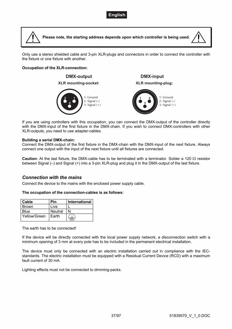
51839570_V_1_0.DOC37/97
Please note, the starting address depends upon which controller is being used.
Only use a stereo shielded cable and 3-pin XLR-plugs and connectors in order to connect the controller withthe fixture or one fixture with another.
Occupation of the XLR-connection:
If you are using controllers with this occupation, you can connect the DMX-output of the controller directlywith the DMX-input of the first fixture in the DMX-chain. If you wish to connect DMX-controllers with otherXLR-outputs, you need to use adapter-cables.
Building a serial DMX-chain:Connect the DMX-output of the first fixture in the DMX-chain with the DMX-input of the next fixture. Alwaysconnect one output with the input of the next fixture until all fixtures are connected.
Caution: At the last fixture, the DMX-cable has to be terminated with a terminator. Solder a 120 Ω resistorbetween Signal (–) and Signal (+) into a 3-pin XLR-plug and plug it in the DMX-output of the last fixture.
Connection with the mainsConnect the device to the mains with the enclosed power supply cable.
The occupation of the connection-cables is as follows:
Cable Pin InternationalBrown Live LBlue Neutral NYellow/Green Earth
The earth has to be connected!
If the device will be directly connected with the local power supply network, a disconnection switch with aminimum opening of 3 mm at every pole has to be included in the permanent electrical installation.
The device must only be connected with an electric installation carried out in compliance with the IEC-standards. The electric installation must be equipped with a Residual Current Device (RCD) with a maximumfault current of 30 mA.
Lighting effects must not be connected to dimming-packs.

51839570_V_1_0.DOC38/97
OPERATIONAfter you connected the effect to the mains, the DJ-HEAD 575 SPOT starts running. During the Reset, themotors are trimmed and the device is ready for use afterwards.
Stand Alone operationIn the Stand Alone mode, the DJ-HEAD 575 SPOT can be used without controller.Disconnect the DJ-HEAD 575 SPOT from the controller and call the internal program.
Please refer to the instructions under Control Board.
DMX-controlled operationYou can control the projectors individually via your DMX-controller. Every DMX-channel has a differentoccupation with different features. The individual channels and their features are listed under DMX-protocol.
AddressingThe Control Board allows you to assign the DMX starting address, which is defined as the first channel fromwhich the DJ-HEAD 575 SPOT will respond to the controller.If you set, for example, the address to channel 17, the DJ-HEAD 575 SPOT will use the channel 17 to 32 forcontrol.Please, be sure that you don’t have any overlapping channels in order to control each DJ-HEAD 575 SPOTcorrectly and independently from any other fixture on the DMX-chain.If several DJ-HEAD 575 SPOT are addressed similarly, they will work synchronically.
For address setting follow this procedure:1. Switch on the DJ-HEAD 575 SPOT and wait until the fixture reset has finished ("rSt" is flashing at thedisplay).2. Press the [Mode] key in order to access the main menu. Browse through the menu by pressing the [Up]and [Down] keys until the display shows "A001". Confirm by pressing [Enter] key and the letter "A" willflash.3. Use the [Up] and [Down] keys to select the desired address.4. Confirm by pressing [Enter] or [Mode] to cancel.
Controlling:After having addressed all DJ-HEAD 575 SPOT, you may now start operating these via your lightingcontroller.
Note:The modes of DMX 512 data and lamp are shown via the display:After switching on, the device will automatically detect whether DMX 512 data is received or not. If the datais received, the the display will show "A001" with the actually set address. If there is no data received at theDMX-input, the display will flash.This situation can occur if:- the 3 PIN XLR plug (cable with DMX signal from controller) is not connected with the input of the device.- the controller is switched off or defective, if the cable or connector is defective or the signal wires are swapin the input connector.
Note:It’s necessary to insert the XLR termination plug (with 120 Ohm) in the last lighting in the link in order toensure proper transmission on the DMX data link.

51839570_V_1_0.DOC39/97
DMX-protocol 16 Bit-resolution (8 Bit-resolution)
Control-channel 1 (1) - Horizontal movement (Pan) (within 530°)Push slider up in order to move the head horizontally (PAN).Gradual head adjustment from one end of the slider to the other (0-255, 128-center).The head can be stopped at any position you wish.
Control-channel 2 (2) - Vertical movement (Tilt) (within 280°)Push slider up in order to move the head vertically (TILT).Gradual head adjustment from one end of the slider to the other (0-255, 128-center).The head can be stopped at any position you wish.
Control-channel 3 - Pan-movement with 16 Bit-resolution
Control-channel 4 - Tilt-movement with 16 Bit-resolution
Control-channel 5 (3) - Pan/Tilt-speedDecimal Hexad. Percentage S/F Feature
0 0 00 00 0% 0% S Maximum speed (tracking mode)1 249 01 F9 0% 98% F Decreasing speed (vector mode)
250 252 FA FC 98% 99% S Maximum speed (tracking mode), black-out color or gobo changes253 255 FD FF 99% 100% S Maximum speed (tracking mode), black-out while Pan, Tilt moving or
color gobo changes
Control-channel 6 (4) - Switch on/off the lamp, reset, speed control of cooling fanDecimal Hexad. Percentage S/F Feature
0 127 00 7F 0% 50% F Decreasing speed of fan128 139 80 8B 50% 55% S Switch on the lamp, reset, open position140 229 8C E5 55% 90% S No function230 239 E6 EF 90% 94% S Switch off the lamp after 3 seconds240 255 F0 FF 94% 100% S No function
Control-channel 7 (5) - Colour-wheel 1Linear colour change following the movement of the slider.In this way you can stop the colour-wheel in any position - also between two colourscreating double-coloured beams. Between 128 and 190 and between 194 and 255, the colour-wheel rotatescontinuously the so-called "Rainbow" effect.Decimal Hexad. Percentage S/F Feature
0 12 00 0C 0% 5% S Open/white13 25 0D 19 5% 10% S Light Blue26 37 1A 25 10% 15% S Red38 50 26 32 15% 20% S Blue51 63 33 3F 20% 25% S Light green64 76 40 4C 25% 30% S Yellow77 89 4D 59 30% 35% S Magenta90 101 5A 65 35% 40% S Cyan
102 114 66 72 40% 45% S Green115 127 73 7F 45% 50% S Orange128 190 80 BE 50% 75% F Forwards rainbow effect with decreasing speed191 193 BF C1 75% 76% S No rotation194 255 C2 FF 76% 100% F Backwards rainbow effect with increasing speed
0 255 00 FF 0% 100% S Colour macro function (channel 8 set from 128-255) - 64 differentcolours in following order: white, pink, magenta, red, orange, yellow,green, cyan, blue, UV

51839570_V_1_0.DOC40/97
Control-channel 8 (6) - Colour-wheel 2Decimal Hexad. Percentage S/F Feature
0 11 00 0B 0% 4% S White12 23 0C 17 5% 9% S Deep red24 35 18 23 9% 14% S Deep blue36 47 24 2F 14% 18% S Pink48 59 30 3B 19% 23% S Cyan60 71 3C 47 24% 28% S Magenta72 83 48 53 28% 33% S Yellow84 95 54 5F 33% 37% S 6000 K correction filter96 107 60 6B 38% 42% S 3200 K correction filter
108 119 6C 77 42% 47% S UV filter120 127 78 7F 47% 50% S White128 255 80 FF 50% 100% S Enable macro color function on channel 7
Control-channel 9 (7) - Rotating 3-facet-prism, macrosDecimal Hexad. Percentage S/F Feature
0 0 00 00 0% 0% S Open1 63 01 3F 0% 25% F Forwards rotation with decreasing speed
64 64 40 40 25% 25% S No rotation65 127 41 7F 25% 50% F Backwards rotation with increasing speed
128 135 80 87 50% 53% S Macro 1136 143 88 8F 53% 56% S Macro 2144 151 90 97 56% 59% S Macro 3152 159 98 9F 60% 62% S Macro 4160 167 A0 A7 63% 65% S Macro 5168 175 A8 AF 66% 69% S Macro 6176 183 B0 B7 69% 72% S Macro 7184 191 B8 BF 72% 75% S Macro 8192 199 C0 C7 75% 78% S Macro 9200 207 C8 CF 78% 81% S Macro 10208 215 D0 D7 82% 84% S Macro 11216 223 D8 DF 85% 87% S Macro 12224 231 E0 E7 88% 91% S Macro 13232 239 E8 EF 91% 94% S Macro 14240 247 F0 F7 94% 97% S Macro 15248 255 F8 FF 97% 100% S Macro 16
Control-channel 10 (8) - Static gobo-wheel, gobo shakeDecimal Hexad. Percentage S/F Feature
0 7 00 07 0% 3% S Open8 15 08 0F 3% 6% S Gobo 1
16 23 10 17 6% 9% S Gobo 224 31 18 1F 9% 12% S Gobo 332 39 20 27 13% 15% S Gobo 440 47 28 2F 16% 18% S Gobo 548 55 30 37 19% 22% S Gobo 656 63 38 3F 22% 25% S Gobo 764 71 40 47 25% 28% S Gobo 872 79 48 4F 28% 31% S Gobo 980 95 50 5F 31% 37% F Gobo 1 shake with variable speed96 111 60 6F 38% 44% F Gobo 2 shake with variable speed
112 127 70 7F 44% 50% F Gobo 3 shake with variable speed128 143 80 8F 50% 56% F Gobo 4 shake with variable speed

51839570_V_1_0.DOC41/97
144 159 90 9F 56% 62% F Gobo 5 shake with variable speed160 175 A0 AF 63% 69% F Gobo 6 shake with variable speed176 191 B0 BF 69% 75% F Gobo 7 shake with variable speed192 207 C0 CF 75% 81% F Gobo 8 shake with variable speed208 223 D0 DF 82% 87% F Gobo 9 shake with variable speed224 255 E0 FF 88% 100% F Gobo wheel rotation from with increasing speed
Control-channel 11 (9) - Rotating gobo-wheelDecimal Hexad. Percentage S/F Feature
0 31 00 1F 0% 12% S Open32 63 20 3F 13% 25% S Rot. gobo 164 95 40 5F 25% 37% S Rot. gobo 296 127 60 7F 38% 50% S Rot. gobo 3
128 159 80 9F 50% 62% S Rot. gobo 4160 191 A0 BF 63% 75% S Rot. gobo 5192 223 C0 DF 75% 87% S Rot. gobo 6224 255 E0 FF 88% 100% F Rotating gobo-wheel cont. rotation with increasing speed
Control-channel 12 (10)- Rotating gobo index, gobo rotationDecimal Hexad. Percentage S/F Feature
0 127 00 7F 0% 50% S Gobo indexing128 191 80 BF 50% 75% F Forwards gobo rotation with decreasing speed192 192 C0 C0 75% 75% S No rotation193 255 C1 FF 76% 100% F Backwards gobo rotation with increasing speed
Control-channel 13 (11) - IrisDecimal Hexad. Percentage S/F Feature
0 0 00 00 0% 0% S Open1 179 01 B3 0% 70% F Max. diameter to min. diameter
180 191 B4 BF 71% 75% F Closed192 223 C0 DF 75% 87% F Pulse closing with increasing speed224 255 E0 FF 88% 100% F Pulse opening with decreasing speed
Control-channel 14 (12) - Focus & ZoomDecimal Hexad. Percentage S/F Feature
0 85 00 55 0% 33% F Zoom 1 & Continuous adjustment from near to far86 170 56 AA 34% 67% F Zoom 2 & Continuous adjustment from near to far
171 255 AB FF 67% 100% F Zoom 3 & Continuous adjustment from near to far
Control-channel 15 (13) Shutter, strobeDecimal Hexad. Percentage S/F Feature
0 31 00 1F 0% 12% S Shutter closed32 63 20 3F 13% 25% S No function (shutter open)64 95 40 5F 25% 37% F Strobe-effect with increasing speed (max. 10 flashes/sec.)96 127 60 7F 38% 50% S No function (shutter open)
128 159 80 9F 50% 62% F Pulse effect in sequence160 191 A0 BF 63% 75% S No function (shutter open)192 223 C0 DF 75% 87% F Random strobe-effect with increasing speed224 255 E0 FF 88% 100% S No function (shutter open)
Control-channel 16 (14) - Dimmer intensityDecimal Hexad. Percentage S/F Feature
0 255 00 FF 0% 100% F Gradual adjustment of the dimmer intensity from 0 to 100 %

51839570_V_1_0.DOC42/97
Control BoardThe Control Board situated on the top side of the DJ-HEAD 575 SPOT offers several features. You cansimply set the lighting address, read the number of lamp or unit hours, switch on and off the lamp, rundemonstration sequences, make a reset and also use special functions for manual control and servicepurposes.The main menu is accessed by pressing the [Mode] key - press this one so many times until the displayshows message "A001" (with actually stored address). Browse through the menu by the pressing [Up] and[Down] keys - the display shows step by step these messages: A001, rPAn, rTilt, 16br, Lati, Poti, LAMP,dEMo, rESE, SPEC. Press [Enter] if you wish to select one of them. The functions provided are described inthe following sections and the function hierarchy is shown below.
Main functions - DMX 512 Address settings
The letter "A" flashes. Use the [Up] and [down] keys to select required address (001 - 512) and press[Enter] to confirm or [Mode] to cancel and return to the main menu.
- Pan reverseThis function allows you to invert the Pan-movement. Use the [Up] and [Down] keys to select "On" if youwish this feature or "Off" if you don’t wish this feature and press [Enter] to confirm or [Mode] to cancel andreturn to the main menu.
- Tilt reverseThis function allows you to invert the Tilt-movement. Use the [Up] and [Down] keys to select "On" if youwish this feature or "Off" if you don’t wish this feature and press [Enter] to confirm or [Mode] to cancel andreturn to the main menu.
- Movement resolutionBy this function you can adjust the desired movement resolution 8 or 16 bit. Use the [Up] and [Down] keys toselect ‘On’ if you wish the 16bit high resolution or "Off" if you wish only 8 bit resolution and press [Enter] toconfirm or [Mode] to cancel and return to the main menu.Note:If you adjust the 16 bit resolution the fixture will occupy 16 DMX channels, if you adjust the 8 bit resolution,the fixture will be operated by only 14 DMX channels. Please, check the DMX protocol.
- Lamp On timeThis option enables you to read the total number of hours that the lamp has been powered on. Press [Enter]or [Mode] to return to the main menu. In order to reset the counter to 0, you have to hold the Up- and Down-button and press the Enter-button.
- Power On timeBy this option you can read the total number of hours that the DJ-HEAD 575 SPOT has been powered on.Press [Enter] or [Mode] to return to the main menu.
- Switch on / off the lampUse the [Up] and [Down] keys to select "On" if you wish the switch on the lamp or "Off" if you wish switchoff the lamp and press [Enter] to confirm or [Mode] to cancel and return to the main menu.
- Demo sequencesThis function allows you to run a special demo-test sequences without an external controller, which will showyou some possibilities of using DJ-HEAD 575 SPOT . Press [Up] and [Down] keys to select the "Mod1" or"Mod2" sequences. The "Mod1" is suitable for projections on the wall, ceilling or ground without any head-movement, the "Mod2" uses all DJ-HEAD 575 SPOT functions and therefore is good for a completeintroduction of the fixture.

51839570_V_1_0.DOC43/97
- Reset FunctionPress [Enter] key to run reset. This option enables the DJ-HEAD 575 SPOT to index all effects (functions)and return to their standard positions.
SPEC -Special functionsUse the [Up] and [Down] keys to browse through the special functions and select the one by pressing[Enter].
- Manual control of effectsThis function allows you to control manually the channel functions of the fixture. Use the [Up] and [Down]keys to select desired function and press [Enter] to adjust the effect or [Mode] to cancel and return to themenu.
- Lamp On automaticallyThis menu allows you to turn the lamp on after switching the fixture on and switch on/off the lamp lightsensor.
- Lamp On after switching the fixture onThis function enables to switch on the lamp automatically after switching on the fixture. Use the[Up] and [Down] keys to select „On” if you wish to switch on the lamp automatically afterswitching on the fixture or „Off” if you wish the lamp off after switching on the fixture and press[Enter] to confirm or [Mode] to cancel and return to the menu.
- Switch On/Off the lamp light sensorUse the [Up] and [Down] keys to select "On" if you wish to switch the lamp light sensor On andpress [Enter] to confirm or [Mode] to cancel and return to the menu.The option"On" is for thestandard operation.Use the [Up] and [Down] keys to select "Off" if you wish to switch the lamp light sensor Off andpress [Enter] to confirm or [Mode] to cancel and return to the menu.Important: The option"Off" is for "emergency operation" only if the lamp light sensor isdefective and you will wait for a delivery of the spare light sensor! If the lamp light sensorwas switched Off, the error messages "LAEr,SnEr,HEAt" will not appear on the display (onlythe message "HEAt" will appear if the lamp was turned Off and On within 5 minutes ) and atswitching On of the lamp the electronics will still try to ignite the lamp until it shines (even whenthe lamp is damaged or absent), on this account some electronics parts could be damaged!
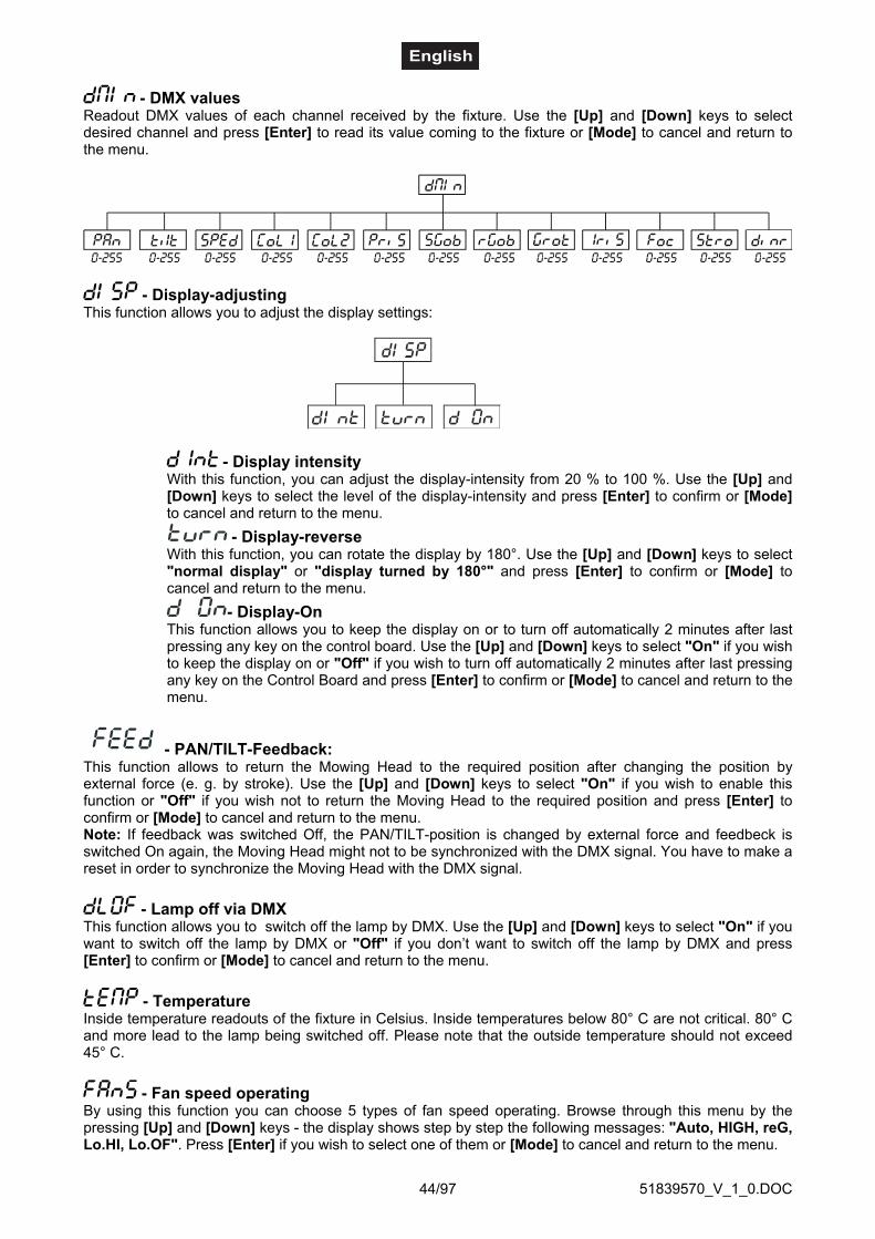
51839570_V_1_0.DOC44/97
- DMX valuesReadout DMX values of each channel received by the fixture. Use the [Up] and [Down] keys to selectdesired channel and press [Enter] to read its value coming to the fixture or [Mode] to cancel and return tothe menu.
- Display-adjustingThis function allows you to adjust the display settings:
- Display intensityWith this function, you can adjust the display-intensity from 20 % to 100 %. Use the [Up] and[Down] keys to select the level of the display-intensity and press [Enter] to confirm or [Mode]to cancel and return to the menu.
- Display-reverseWith this function, you can rotate the display by 180°. Use the [Up] and [Down] keys to select"normal display" or "display turned by 180°" and press [Enter] to confirm or [Mode] tocancel and return to the menu.
- Display-OnThis function allows you to keep the display on or to turn off automatically 2 minutes after lastpressing any key on the control board. Use the [Up] and [Down] keys to select "On" if you wishto keep the display on or "Off" if you wish to turn off automatically 2 minutes after last pressingany key on the Control Board and press [Enter] to confirm or [Mode] to cancel and return to themenu.
- PAN/TILT-Feedback:This function allows to return the Mowing Head to the required position after changing the position byexternal force (e. g. by stroke). Use the [Up] and [Down] keys to select "On" if you wish to enable thisfunction or "Off" if you wish not to return the Moving Head to the required position and press [Enter] toconfirm or [Mode] to cancel and return to the menu.Note: If feedback was switched Off, the PAN/TILT-position is changed by external force and feedbeck isswitched On again, the Moving Head might not to be synchronized with the DMX signal. You have to make areset in order to synchronize the Moving Head with the DMX signal.
- Lamp off via DMXThis function allows you to switch off the lamp by DMX. Use the [Up] and [Down] keys to select "On" if youwant to switch off the lamp by DMX or "Off" if you don’t want to switch off the lamp by DMX and press[Enter] to confirm or [Mode] to cancel and return to the menu.
- TemperatureInside temperature readouts of the fixture in Celsius. Inside temperatures below 80° C are not critical. 80° Cand more lead to the lamp being switched off. Please note that the outside temperature should not exceed45° C.
- Fan speed operatingBy using this function you can choose 5 types of fan speed operating. Browse through this menu by thepressing [Up] and [Down] keys - the display shows step by step the following messages: "Auto, HIGH, reG,Lo.HI, Lo.OF". Press [Enter] if you wish to select one of them or [Mode] to cancel and return to the menu.
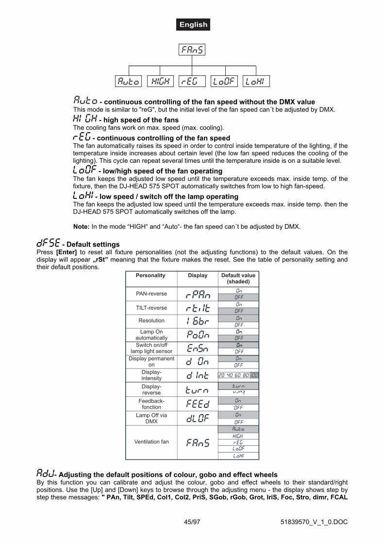
51839570_V_1_0.DOC45/97
- continuous controlling of the fan speed without the DMX valueThis mode is similar to "reG", but the initial level of the fan speed can´t be adjusted by DMX.
- high speed of the fansThe cooling fans work on max. speed (max. cooling).
- continuous controlling of the fan speedThe fan automatically raises its speed in order to control inside temperature of the lighting, if thetemperature inside increases about certain level (the low fan speed reduces the cooling of thelighting). This cycle can repeat several times until the temperature inside is on a suitable level.
- low/high speed of the fan operatingThe fan keeps the adjusted low speed until the temperature exceeds max. inside temp. of thefixture, then the DJ-HEAD 575 SPOT automatically switches from low to high fan-speed.
- low speed / switch off the lamp operatingThe fan keeps the adjusted low speed until the temperature exceeds max. inside temp. then theDJ-HEAD 575 SPOT automatically switches off the lamp.
Note: In the mode “HIGH“ and “Auto“- the fan speed can´t be adjusted by DMX.
- Default settingsPress [Enter] to reset all fixture personalities (not the adjusting functions) to the default values. On thedisplay will appear „rSt” meaning that the fixture makes the reset. See the table of personality setting andtheir default positions.
PAN-reverse
TILT-reverse
Resolution
Lamp Onautomatically
Display permanenton
Display-intensity
Display-reverse
Feedback-fonction
Lamp Off viaDMX
Ventilation fan
Display Default value(shaded)
Personality
Switch on/offlamp light sensor
- Adjusting the default positions of colour, gobo and effect wheelsBy this function you can calibrate and adjust the colour, gobo and effect wheels to their standard/rightpositions. Use the [Up] and [Down] keys to browse through the adjusting menu - the display shows step bystep these messages: " PAn, Tilt, SPEd, Col1, Col2, PriS, SGob, rGob, Grot, IriS, Foc, Stro, dimr, FCAL

51839570_V_1_0.DOC46/97
" by which you can adjust the fixture to the required / desired position (0-255) before the function calibration.Then when the positioning is finished use the last "FCAL" function (Fixture calibration).
1. Calibration via the control boardPress [Enter] and the [Up] and [Down] keys in order to display the following messages: "Col1, Col2, PriS,SGob, rGob, Grot " for very smooth function calibration. Select one of them, press [Enter] and use the [Up]and [Down] keys in order to adjust their right value from 0 to 255. Then press [Enter] to confirm or [Mode]to cancel and return to the menu. This can be repeated for each calibration parameter if it is required. Whenthe calibration is finished, it is necessary to use the "ArES" function in order to write the calibration values tothe memory (EEPROM) and to make a reset in order to check the newly adjusted positions of the colour,gobo and effect wheels. When the reset of the fixture is finished, the display will show the "FCAL" message.Press [Enter] to repeat the calibration or [Mode] to return to the "AdJ" menu.
2. Calibration via the external controllerPress [Enter] and the [Up] and [Down] keys in order to display the following messages: "Colo, EFEC,rGob, Grot" - calibration parameters. Select one of them and press [Enter].Now you can calibrate the colour, gobo and effect wheel by your controller. The DMX calibration protocol isdescribed in the table mentioned below.
DMX Calibration protocol:
After having calibrated required functions press [Enter] to confirm (or [Mode] to cancel and return to themenu without reset by the "ArES" function) and use the "ArES" function in order to write the calibrationvalues to the memory (EEPROM) and to make a reset in order to check the new adjusted positions of thecolour, effect and rot. gobo wheels and gobo indexing.
DMX Channel 1 2 3 4 5 6 7 8
COL.1 COL.2 SGOB RGOB GROT - COLOURS 1 COLOURS 2CALIBRATION
0 - 255CALIBRATION
0 - 255CALIBRATION
0 - 255CALIBRATION
0 - 255CALIBRATION
0 - 255-
STANDARD PROTOCOL
STANDARD PROTOCOL
DMX Channel 9 10 11 12 13 14 15 16
PRISMSTATIC GOBOS
ROTATING GOBOS
GOBO ROTATION
IRIS FOCUS STROBE DIMMER
STANDARD PROTOCOL
STANDARD PROTOCOL
STANDARD PROTOCOL
STANDARD PROTOCOL
STANDARD PROTOCOL
STANDARD PROTOCOL
STANDARD PROTOCOL
STANDARD PROTOCOL
Function
SMOOTH MICROSTEP MOVEMENT
Function

51839570_V_1_0.DOC47/97
Error MessagesWhen you turn on the fixture, it will make a reset first. The display may show an error message whilethere are problems with one or more channels. The error message stands for the channels equippedwith a testing sensor.For example, when the display shows “C2Er”, it means there is some error in the color wheel 2channel. If there are some errors on several channels at the same time, you may see the errormessages flash repeatly for 5 times, and then the fixture will generate a reset signal, all the steppermotors will reset. If the error messages maintain after performing reset more than 3 times, it willdetect whether the fixture has more than 3 errors. If the fixture has more than 3 errors (including 3errors), all the channels can not work properly; but if the fixture has less than 3 errors, only thechannels which have errors can not work properly, others can work as usual.
The respective error message will appear after the reset of the fixture if the channels magnetic-indexingcircuit malfunction (sensor failed or magnet missing) or the stepping-motor is defective (or its driving IC onthe main PCB). The channel feature is not located in the default position after the reset.
The different error messages are:
This message appears if you try to switch on the lamp within 5 minutes after having switched it off (the lampis too hot). The message will appear on the display if the lamp doesn't ignite within 28 seconds. The DJ-HEAD 575 SPOT will store this information and automatically ignite the lamp when the 5 minutes period hasexpired.Caution: Please note that this function is disabled if the lamp light sensor is switched off (function "EnSn").
The ignition of the lamp is seven times unsuccessful (the HEAt message appeared six times before), and thedisplay shows "LAEr", meaning that the lamp could be damaged or even missed, the fixture is overheating(this can occur if the ambient temperature is 45° C or more) or there could be a failure on the ignitor orballast.Please place or replace the lamp, check the ambient temperature or contact your dealer if the situation wasnot caused by the lamp.Caution: Please note that this function is disabled if the lamp light sensor is switched off (function "EnSn").
This message informs you that the main PCB does not communicate correctly with the Control Board.
(Color-wheel 1 error) This message will appear after the reset of the fixture if the magnetic-indexing circuitmalfunctions (sensor failed or magnet missing) or the stepping-motor is defective (or its driver circuit on themain PCB). The color-wheel is not located in the default position after the reset.
(Color-wheel 2 error) This message will appear after the reset of the fixture if the magnetic-indexing circuitmalfunctions (sensor failed or magnet missing) or the stepping-motor is defective (or its driver circuit on themain PCB). The color-wheel is not located in the default position after the reset.
(Rotating gobo-wheel error) This message will appear after the reset of the fixture if the magnetic-indexingcircuit malfunctions (sensor failed or magnet missing) or the stepping-motor is defective (or its driver circuiton the main PCB). The rotating gobo-wheel is not located in the default position after the reset.
(Rotating gobo indexing error) This message will appear after the reset of the fixture and if the magnetic-indexing circuit malfunctions (sensor failed or magnet missing) or the stepping-motor is defective (or its drivercircuit on the main PCB). The rotating gobo is not located in the default position after the reset.
(Static gobo-wheel error) This message will appear after the reset of the fixture if the magnetic-indexingcircuit malfunctions (sensor failed or magnet missing) or the stepping-motor is defective (or its driver circuiton the main PCB). The gobo-wheel is not located in the default position after the reset.
(Prism-wheel error) This message will appear after the reset of the fixture if the magnetic-indexing circuitmalfunctions (sensor failed or magnet missing) or the stepping-motor is defective (or its driver circuit on themain PCB). The prism-wheel is not located in the default position after the reset.

51839570_V_1_0.DOC48/97
This error message informs you that the fixture was overheating (occured if the ambient temperature is 45° Cor more) and that the relay switched off the lamp. This message will appear on the display until thetemperature will be on a suitable level, then the display will show the HEAt message meaning the lamp is toohot (explanation see above).
This message appears if the lamp lighting sensor is failed. Please contact your dealer.Caution: Please note that this function is disabled if the lamp light sensor is switched off (function "EnSn").
This message will appear if the fixture was shortly disconnect from the mains.
(PAN-yoke movement error) This message will appear after the reset of the fixture if the yoke’s magnetic-indexing circuit malfunction (sensor failed or magnet missing) or the stepping-motor is defective (or its drivingIC on the main PCB). The yoke is not located in the default position after the reset.
(TILT-head movement error) This message will appear after the reset of the fixture if the head’s magnetic-indexing circuit malfunctions (sensor failed or magnet missing) or the stepping-motor is defective (or itsdriving IC on the main PCB). The head is not located in the default position after the reset.
This message will appear if the frequency of the mains is not standard 50 or 60 Hz.
CLEANING AND MAINTENANCEThe operator has to make sure that safety-relating and machine-technical installations are inspected by anexpert after every four years in the course of an acceptance test.
The operator has to make sure that safety-relating and machine-technical installations are inspected by askilled person once a year.
The following points have to be considered during the inspection:1) All screws used for installing the devices or parts of the device have to be tighly connected and must not
be corroded.2) There must not be any deformations on housings, fixations and installation spots (ceiling, suspension,
trussing).3) Mechanically moved parts like axles, eyes and others must not show any traces of wearing (e.g. material
abrading or damages) and must not rotate with unbalances.4) The electric power supply cables must not show any damages, material fatigue (e.g. porous cables) or
sediments. Further instructions depending on the installation spot and usage have to be adhered by askilled installer and any safety problems have to be removed.
Disconnect from mains before starting maintenance operation!
DANGER TO LIFE!
We recommend a frequent cleaning of the device. Please use a moist, lint-free cloth. Never use alcohol orsolvents!
The lens has to be replaced when it is obviously damaged,so that its function is impaired, e. g. due to cracks or deep scratches!
CAUTION!
The objective lens will require weekly cleaning as smoke-fluid tends to building up residues, reducing thelight-output very quickly. The cooling-fans should be cleaned monthly.

51839570_V_1_0.DOC49/97
Do not operate this device with opened cover!
The gobos may be cleaned with a soft brush. The interior of the fixture should be cleaned at least annuallyusing a vacuum-cleaner or an air-jet.The dichroic colour-filters, the gobo-wheel and the internal lenses should be cleaned monthly.
To ensure a proper function of the gobo-wheel, we recommend lubrication in six month intervals. Thequantity of oil must not be excessive in order to avoid that oil runs out when the gobo-wheel rotates.
There are no serviceable parts inside the device except for the lamp and the fuse. Maintenance and serviceoperations are only to be carried out by authorized dealers.Please refer to the instructions under "Installing/Replacing the lamp".
Replacing the fuseIf the lamp burns out, the fine-wire fuse of the device might fuse, too. Only replace the fuse by a fuse ofsame type and rating.
Before replacing the fuse, unplug mains lead.
Procedure:Step 1: Unscrew the fuseholder on the rearpanel with a fitting screwdriver from the housing (anti-
clockwise).Step 2: Remove the old fuse from the fuseholder.Step 3: Install the new fuse in the fuseholder.Step 4: Replace the fuseholder in the housing and fix it.
Should you need any spare parts, please use genuine parts.
If the power supply cable of this device becomes damaged, it has to be replaced by a special power supplycable available at your dealer.
Should you have further questions, please contact your dealer.
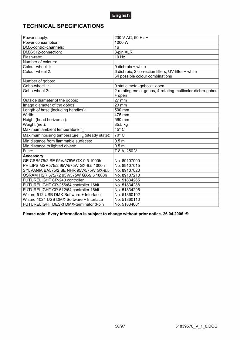
51839570_V_1_0.DOC50/97
TECHNICAL SPECIFICATIONS
Power supply: 230 V AC, 50 Hz ~Power consumption: 1000 WDMX-control-channels: 16DMX-512-connection: 3-pin XLRFlash-rate: 10 HzNumber of colours:Colour-wheel 1: 9 dichroic + whiteColour-wheel 2: 6 dichroic, 2 correction filters, UV-filter + white
64 possible colour combinationsNumber of gobos:Gobo-wheel 1: 9 static metal-gobos + openGobo-wheel 2: 2 rotating metal-gobos, 4 rotating multicolor-dichro-gobos
+ openOutside diameter of the gobos: 27 mmImage diameter of the gobos: 23 mmLength of base (including handles): 500 mmWidth: 475 mmHeight (head horizontal): 560 mmWeight (net): 35.5 kgMaximum ambient temperature Ta: 45° CMaximum housing temperature TB (steady state): 70° CMin.distance from flammable surfaces: 0.5 mMin.distance to lighted object: 0.5 mFuse: T 8 A, 250 VAccessory:GE CSR575/2 SE 95V/575W GX-9,5 1000h No. 89107000PHILIPS MSR575/2 95V/575W GX-9.5 1000h No. 89107015SYLVANIA BA575/2 SE NHR 95V/575W GX-9,5 No. 89107020OSRAM HSR 575/72 95V/575W GX-9.5 1000h No. 89107210FUTURELIGHT CP-240 controller No. 51834265FUTURELIGHT CP-256/64 controller 16bit No. 51834288FUTURELIGHT CP-512/64 controller 16bit No. 51834295Wizard-512 USB DMX-Software + Interface No. 51860102Wizard-1024 USB DMX-Software + Interface No. 51860110FUTURELIGHT DES-3 DMX-terminator 3-pin No. 51834001
Please note: Every information is subject to change without prior notice. 26.04.2006 ©
51839570_V_1_0.DOC51/97
MODE D'EMPLOI
DJ-HEAD 575 SPOTPro-Head-Spot
ATTENTION!Protéger de l'humidité.Débrancher avant d’ouvrier le boîtier!
Pour votre propre sécurité, veuillez lire ce mode d'emploi avec attention avant la première mise enservice.
Toute personne ayant à faire avec le montage, la mise en marche, le maniement et l’entretien de cetappareil doit- être suffisamment qualifiée- suivre strictement les instructions de service suivantes- considérer ce mode d'emploi comme faisant partie de l'appareil- conserver le mode d'emploi pendant la durée de vie de l'article- transmettre le mode d'emploi à un éventuel acheteur ou utilisateur de l'appareil- télécharger la version ultérieure du mode d'emploi d'Internet
INTRODUCTIONNous vous remercions d'avoir choisi un FUTURELIGHT DJ-HEAD 575 SPOT. Vous êtes en possession d'uneffet lumineux puissant aux possibilités multiples.
Sortez le DJ-HEAD 575 SPOT de son emballage.
Inclus dans la livraison
1 Appareil1 Mode d’emploi1 Câble XLR m.-XLR f., 5m, symétrique, noir 3022050N2 Support de fixation

51839570_V_1_0.DOC52/97
INSTRUCTIONS DE SÉCURITÉ
ATTENTION!Soyez prudent, lors de manipulations électriques avec une tension dangereuse vousêtes soumis à des risques d'électrocution!
Cet appareil a quitté les ateliers dans un état irréprochable. Pour assurer un bon fonctionnement, sansdanger, l'utilisateur doit suivre les instructions contenues dans ce mode d'emploi.
Attention:Tout dommage occasionné par la non observation des instructions de montage ou d'utilisation n'estpas couvert par la garantie.
L'appareil ne doit pas être mis en service lorsqu'il à été transporté d'un endroit froid à un endroit chaud. Il seforme de la condensation qui pourrait endommager l'appareil. Laissez celui-ci atteindre la températureambiante avant de le mettre en service.
Avant tout, assurez-vous que l'appareil n'a pas subi de dommages lors de son transport. Si l'appareil ou lecâble d'alimentation est endommagé, ne jamais mettre l'appareil en service. Contactez immédiatement votrerevendeur.
La construction de l'appareil correspond à la classe de protection I. La fiche secteur doit être connectéeuniquement à une prise secteur à contact de protection, la tension et la fréquence de laquelle correspondexactement à plaque signalétique des l'appareil. Des tensions inappropriées et des prises secteurinappropriées peuvent mener à la destruction de l'appareil et à des électrocutions mortelles.
Toujours connecter la fiche secteur en dernier. Il faut inserer la fiche secteur de maniére non-violente. Faitesattention à une position bien fixée de la fiche secteur.
Ne laissez pas entrer le câble secteur en contact avec d'autres câbles! Soyez prudent lors de lamanipulation des câbles secteur et des alimentations secteur. Ne touchez jamais ces parties avec des mainsmouillées! Des mains mouillées peuvent causer des électrocutions mortelles.
Ne pas modifier, plier, charger de manière mécanique, charger de pression, tirer, chauffer et ne paspositionner des câbles secteur à proximité de sources de chaleur ou de froid. En cas de non-respect desdommages du câble secteur, des feus ou des électrutions mortelles peuvent en résulter.
L'insertion de câble ou l'accouplement à l'appareil ne doit pas être chargé par tension. Il faut toujours avoirune longeur de câble vers l'appareil, manque de quoi le câble peut être endommagé, ce qui peut mener àdes électrocutions mortelles.
Prenez garde de ne pas coincer ou abimer le câble d'alimentation. Contrôler l'appareil et les câblesd'alimentation régulièrement.
En cas d'utilisation de rallonges il faut assurer que la section du fil est admissible pour l'alimentation encourant nécessaire pour l'appareil. Toutes les indications d'avertissement pour le câble secteur sont aussivalables pour des rallonges éventuellement utilisées.
Débranchez l'appareil lorsque vous ne l'utilisez pas et avant de le nettoyer. Pour ce faire, utilisez lessurfaces de maintien sur la fiche; ne tirez jamais le câble secteur! Sinon, le câble et la fiche peuvent êtreendommagés, ce qui peut mener à des électrocutions mortelles. Si la fiche ou l'interrupteur de l'appareil nesont pas accessibles, par exemple parce qu'ils sont enfermés par d'autres pièces, il faut procéder à unedisjonction de tous les pôles du côté secteur.
Si la fiche secteur ou l'appareil sont couverts de poussière, il faut le mettre hors service, il faut interrompre lecircuit sur tous les pôles, et nettoyer l'appareil avec un chiffon sec. La poussière peut réduire l'isolation, cequi peut mener à des électrocutions mortelles. Des encrassements plus importants dans l'appareil et surl'extérieur de l'appareil ne doivent être enlevés que par un technicien compétent.

51839570_V_1_0.DOC53/97
Dans aucun cas des liquides de tout genre doivent pénétrer dans des fiches secteur, des connecteurs oudans des ouvertures d'appareil ou dans des fentes d'appareil. S'il y a un doute sur le fait que même unequantité minimale de liquide aurait pénétré dans l'appareil, il faut immédiatement séparer l'appareil dusecteur avec tous les pôles. C'est valable aussi, si l'appareil a été exposé à une humidité de l'air éelvée.Même si l'appareil apparemment fonctionne toujours, il oit être examiné par un technicien compétent, si parla pénétration de liquide des isolations ont été éventuellement endommagées. Des isolations réduitespeuvent causer des électrocutions mortelles.
Des objets étranges ne doivent pas entrer dans l'appareil. C'est valable particulièrement pour des piècesmétalliques. Au cas où mêmes des pièces métalliques les plus petites comme des agrafes et trombones oudes éclats métalliques doivent entrer dans l'appareil, il faut immédiatement mettre l'appareil hors service et leséparer du secteur avec tous les pôles (tirer la fiche secteur). Des dysfonctionnements et court-circuitspeuvent causer des blessures mortelles.
Lors de la première mise en service, il peut y avoir une émission de fumée et d'odeurs. Ceci n'est pas dû àun défaut de l'appareil.
Danger d'incendie! Ne jamais installer l'appareil sur des surfaces facilement inflammables (p.ex. tapis defoire)!
Attention: L’appareil produit des témperatures excessives!
Evitez de faire des effets "flash" avec cet appareil en l'allumant et l'éteignant continuellement. Cela réduitconsidérablement la durée de vie des ampoules.
RISQUE DE MAL!Ne jamais regarder directement à la source de lumière, parce que des personnes sen-sibles peuvent subir une attaque épileptique (surtout valable pour des épileptiques)!
Tenir les enfants et les novices éloignés de l'appareil.
Ne jamais faire marcher sans surveillance.
EMPLOI SELON LES PRESCRIPTIONSCet appareil est un spot avec tête rotative pour créer des effets décoratifs. Cet appareil doit seulement êtreconnecté avec une tension alternative de 230 V, 50 Hz et a été conçu pour un usage dans des locaux clos.
Cet appareil est prévu pour des utilisations professionnelles, p. ex. sur scènes, en discothèques, théâtresetc.
Les effets lumineux ne sont pas conçus pour un usage continu. Accordez leur une pause de temps à autre,cela prolongera leur durée de vie.
Eviter les secousses et l’emploi de la force lors de l’installation ou de l’utilisation de l’appareil.
Il ne faut jamais lever l'appareil par la tête de projecteur, puisque autrement la mécanique pourrait êtreendommagée. Toujours prendre l'appareil par les poignées de transport.
Quand vous choisissez le lieu d’installation, évitez toutefois les endroits humides, poussiéreux ou tropchauds. Assurez-vous que les câbles ne traînent pas au sol. Assurez-vous que l'appareil ne puisse pas êtretouché ou renversé. Il en va de votre propre sécurité et de celle d’autrui.
L'appareil ne doit pas être utilisé ou stocké dans un environnement humide, dans lequel on doit s'attendre àdes projections d'eau, de la pluie, de l'humidité ou du brouillard. L'humidité ou une humidité de l'air trèsélevée peut réduire l'isolation et mener à des électrocutions mortelles. Lors de l'utilisation de machines àfumée il faut faire attention à ce que l'appareil ne soit jamais exposé directement au jet de fumée et qu'il soit

51839570_V_1_0.DOC54/97
mis en service au moins à 0,5 m de distance d'une machine de fumée. L'espace doit être seulement saturéde fumée de sorte qu'il a ait encore une bonne vue d'au moins 10 m.
Il faut que la température ambiante soit comprise entre -5° C et +45° C. Ne pas exposer l'appareildirectement aux rayons solaires (lors d'un transport dans un véhicule fermé par exemple).
Lorsqu'une température ambiante est de +45° C l'humidité relative atmosphérique ne doit pas dépasser 50%.
Cet appareil ne peut être mis en service qu'à une altitude entre -20 et 2000 m au-dessus du niveau de lamer.
N'utilisez pas l'appareil pendant un orage, puisqu'un survoltage pourrait détruire l'appareil. Lors d'un orage,séparez l'appareil du secteur avec tous les pôles (tirer la fiche secteur).
Le symbole - - -m indique la distance minimale des objets illuminés. Ne jamais prendre une distance en-dessous de la valeur entre la sortie de lumière et la surface à illuminer!
Seulement installer l'appareil sur des surfaces non enflammables. Afin d'assurer une ventilation optimale, ilest nécéssaire de laisser un espace d'au moins 50 cm autour de l'appareil. Veuillez respecter que desobjects sensibles à la chaleur puissent être corroyés ou endommagés à cause de la chaleur émise.
Lors de l'installation du projecteur, du démontage du projecteur et pendant l'exécution des travaux de servicefaites attention à ce que la zone en-dessous du lieu d'installation soit bouclée.
Pour le montage par dessus de la tête (hauteur de montage >100 cm), il faut toujours fixer l'appareil avecune élingue de sécurité appropriée. Il faut accrocher l'élingue de sécurité aux fixations prévues à cet effet.Ne jamais accrocher l'élingue de sécurité aux poignées de transport!
N'utilisez l'appareil qu'après vous êtes assuré que le boîtier est bien fermé et toutes les vis nécessaires ontété complètement fixées.
Il ne faut jamais allumer la lampe, si la lentille d'objectif ou les couvercles de boîtier ont été enlevé, puisqu'iléeiste un danger d'explosion aux lampes à décharge et il se produit un rayonnement ultraviolet fort, qui peutcauser des brûlures.
La température maximale ambiante Ta = 45° C ne doit pas être dépassée.
N’utilisez l’appareil qu’après avoir pris connaissance de ses fonctions et possibilités. Ne laissez pas despersonnes incompétentes utiliser cet appareil. La plupart des pannes survenant sur cet appareil sont dues àune utilisation inappropriée par des personnes incompétentes.
Si vous deviez transporter l'appareil, utilisez l'emballage d'origine pour éviter tout dommage.
Notez que pour des raisons de sécurité, il est interdit d'entreprendre toute modification sur l'appareil.
Il est interdit de retirer le code barre de l'appareil. Ceci annulerait toute garantie.
Si l'appareil est utilisé autrement que décrit dans ce mode d'emploi, ceci peut causer des dommages auproduit et la garantie cesse alors. Par ailleurs, chaque autre utilisation est liée à des dangers, comme par ex.court circuit, incendie, électrocution, explosion de lampe, chute etc.
51839570_V_1_0.DOC55/97
DESCRIPTION DE L'APPAREIL
Features
DJ Moving Head puissant• Système de couleurs: 2 roues de couleurs• Roue de couleurs 1 avec 9 filtres de couleurs dichroïques diffèrentes + blanc• Roue de couleurs 2 avec 6 filtres de couleurs dichroïques diffèrentes + blanc et additionellement avecfiltres correcteurs de 3200 K et 6000 K et filtre UV• Jusqu'à 64 couleurs et demi-coloris peuvent être obtenus grâce à deux filtres correcteurs• Effet "rainbow" bidirectionnel• Roue de gobos 1 avec 9 gobos métalliques statiques et ouverts• Avec fonction "gobo shake" pur les gobos rotatifs• Roue de gobos 2 avec 2 gobos métalliques rotatifs, 4 gobos dichroïques multicouleurs et ouverts• Tous les gobos rotatifs peuvent être échangés avec les autres• Grâce à la combinaison du gobo multicouleur et la roue des couleurs plusieurs mélanges de colorispossibles• Prisme à 3 facettes avec rotation rapide• Foyer motoriséee contrôlable par télécommande• Unité combinée shutter/variateur de lumière mécanique pour une variation de lumière douce et effetstroboscopique avec 1 à 10 flashs par seconde• Activation de la lampe par télécommande possible• Fonction macro pour combinaisons entre roue de gobo rotatif et prisme rotatif• Fonction blackout lors d'un mouvement de tête ou sélection des gobos/des couleurs/du prisma• Vitesse du mouvement PAN/TILT par télécommande possible pour but d'une programmation simplifiée• Reset contrôlable par télécommande• Ventilateur silent avec vitesse de ventilateur réglable• 16 canaux DMX - résolution 16 Bit du mouvement Pan/Tilt• 14 canaux DMX - résolution 8 Bit du mouvement Pan/Tilt• Mouvement PAN au dedans de 530°• Mouvement TILT au dedans de 280°• Zoom Multistep motoriséee avec trois angles différents (15°, 18° et 22°)• Iris réglable en continu• Control Board avec affichage 4 positions pour ajuster l'adresse DMX start• Pour lampe MSR 575/2 ou MSR 575• Contrôlable via DMX-512 par chaque contrôleur DMX standard
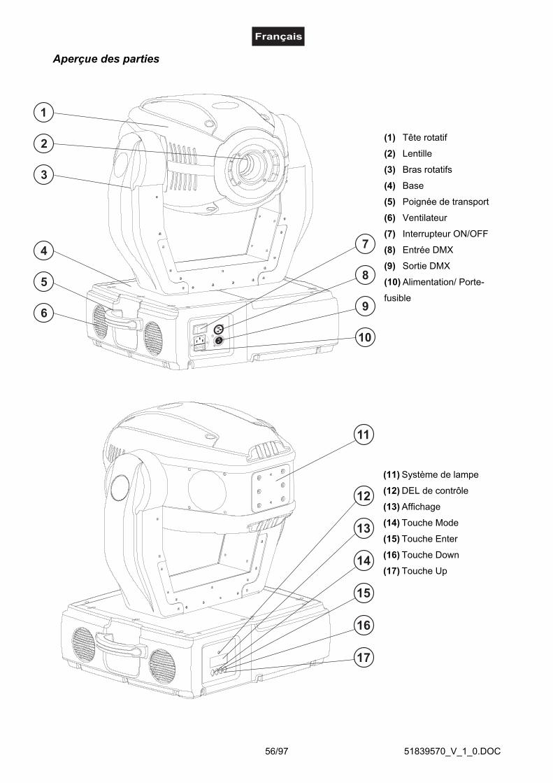
51839570_V_1_0.DOC56/97
Aperçue des parties
(1) Tête rotatif
(2) Lentille
(3) Bras rotatifs
(4) Base
(5) Poignée de transport
(6) Ventilateur
(7) Interrupteur ON/OFF
(8) Entrée DMX
(9) Sortie DMX
(10) Alimentation/ Porte-
fusible
(11) Système de lampe
(12) DEL de contrôle
(13) Affichage
(14) Touche Mode
(15) Touche Enter
(16) Touche Down
(17) Touche Up

51839570_V_1_0.DOC57/97
INSTALLATIONInstaller/Remplacer la lampe
DANGER DE MORT!Toujours mettre hors tension avant de mettre en place l'ampoule!Débrancher avant toute manipulation!
Pour l'installation, vous avez besoin d'une lampe MSR 575/2 ou MSR 575.
La lampe ne peut être changée que si les vêtements de protection apropriés sont utiliés (lunettes deprotection, gants de protection, casque de protection avec visière, tablier de cuir).
La lampe doit être remplacée lorsqu'elle a été endommagéeou déformée par la chaleur!
ATTENTION!
La durée de vie indiquée par le fabriquant ne doit jamais être dépassée. C’est pour cette raison que vousdevez notez avec précaution les heures de fonctionnement de la lampe ou controller le compteur d’heuresrégulièrement et remplacer la lampe à temps.
La lampe usée est à conserver dans un récipiant de protection et à manipuler avec précaution.
La lampe utilisée a une température moyenne de 600° C.
Avant le remplacement de l'ampoule, toujours laisser refroidir (env. 10 minutes) celle-ci etdébrancher l'appareil.
Ne jamais manipuler l'ampoule directement avec les doigts. Veuillez respecter les instructions du fabricant.
Ne pas utiliser des ampoules d’une puissance supérieure, la température dègagée par celles-ci étant trophaute pour cet appareil. En cas de non respect de cette consigne, la garantie n’est plus valable.
Procédure:
Pas 1: Dévissez les vis de fixation X, Y, Z du système de lampe et retirez-le.Pas 2: Quand vous remplacez une lampe, retirez la lampe deféctueuse avant.Pas 3: Insérez la lampe dans le porte-lampe.Pas 4: Replaçez le système de lampe et vissez les vis de fixation.Pas 5: Ajustez la lampe comme décrit sous Ajustage de la lampe.
Ne jamais mettre l’appareil sous tension avant que le boîtierne soit refermé.

51839570_V_1_0.DOC58/97
Ajustage de la lampe
Le porte-lampe de l’appareil est ajusté à l‘usine. Comme leslampes à utiliser diffèrent d’un fabricant à l’autre, il pourraitdevenir nécessaire de procéder à un nouveau ajustage de laposition du porte-lampe.Allumez la lampe, ouvriez le shutter et l'iris, ajustez l'intensitédu dimmeur à 100 % et directionnez le rayon de lumière surune surface plane (mur). Centrez le "Hot Spot" (la partie laplus claire du rayon de lumière) avec les 3 vis "A, B, C”.Tournez un vis pour mover le Hot Spot sur l'image projeté. Sivous ne pouvez pas voir un Hot Spot, ajustez la lampejusqu'à ce que la lumière soit repartie de manière uniforme.Si le Hot Spot semble trop clair, vous pouvez affaiblir sonintensité en mouvant la lampe plus proche au réflecteur. Acette fin, tournez les vis "A, B, C" pour ¼ tours dans le sens
des aiguilles d'une montre, jusqu’à ce que la lumière soit repartie de manière uniforme.Si la lumière semble plus clair au bord extérieur du rayon qu’au centre, la lampe se trouve trop proche auréflecteur. Dans ce cas, éloignez la lampe du réflecteur en tournant les vis "A, B, C" pour ¼ tours dans lesens inverse des aiguilles d'une montre, jusqu’à ce que la lumiere soit repartie de manière uniforme et lerayon semble assez clair.
Introduire/échanger gobos
DANGER DE MORT!Toujours débrancher l’appareil avant de
introduire les gobos!
Quand vous voulez utiliser des formes et dessins différents comme le gobos standards, ou quand vousvoulez échanger gobos, procédez de la manière suivante:
ATTENTION!Ne jamais dévisser les vis des gobo rotatifs.
Autrement les paliers ouvrients!
Rémovez l'anneau de fixation avec un outil approprié. Rétirez le gobo et insérez le nouveau gobo. Pressezl'anneau de fixation et introduisez-le avant le gobo.
ATTENTION!Slot In système de gobo pour échanger les gobos sans outils.
Introduire/échanger les gobo selon la description faite ci-dessus.
51839570_V_1_0.DOC59/97
Montage du projecteur
DANGER DE MORT!Quand installer l'appareil, il faut considerer les instructions de EN 60598-2-17 et desnormes nationales réspectives! L'installation est à faire effectuer par un installateur agrée!
Les dispositifs de suspension du projecteur doivent être construites et conceptionnés de telle manière qu’ilspuissent supporter son charge utile de 10 fois pour 1 heure sans déformation permanente nuisible.
L’installation doit toujours être effectuée avec une deuxième suspension indépendante, par ex. un filet decapture approprié. Cette deuxième suspension doit être conceptionnée et installée de telle manière qu’encas de défaut de la suspension principale aucun part de l’installation ne puisse tomber.
Pendant le montage, l’adaptation et le démontage, la présence inutile dans le secteur de surfaces demouvement, sur des ponts d’illumination, sous des place de travail surélevées ainsi que près d’autres airesde danger est interdite.L’entrepreneur doit assurer à ce que les installations concernant la sécurité technique et la sécurité desmachines soient examinés par des experts.L’entrepreneur doit assurer à ce que les installations concernant la sécurité technique et la sécurité desmachines soient examinés au moins tous les quatre ans par un expert au cadre de l’épreuve de réception.
L’entrepreneur doit assurer à ce que les installations concernant la sécurité technique et la sécurité desmachines soient examinés au moins une fois par an par une personne compétente.Procédure:Dans le cas idéal, le projecteur devrait être installé en dehors du secteur de présence de personnes.
IMPORTANT! LE MONTAGE PAR DESSUS DE LA TETE EXIGE UN HAUT NIVEAU D‘EXPERIENCE. Cecicomprend (mais n’est pas limitée seulement) des calculations pour la définition de la capacité de charge, lematériel d’installation utilisé et des inspections de sécurité régulières du matériel utilisé et du projecteur.N’essayez jamais à procéder à une installation vous-même, si vous ne disposez pas d’une telle qualification,mais en commissionnez un installateur professionnel. Des installations incorrectes peuvent causer desblessures et/ou l’endommagement de propriété.
Il faut installer le projecteur en dehors du secteur d’opération à la main de personnes.
Si le projecteur doit être décroché du plafond ou de poutres élevés, il faut toujours utiliser des systèmes detraverses pour les travaux. Ne jamais installez le projecteur de manière qu’il puisse osciller librement dansl‘espace.
Attention: En tombant, les projecteurs peuvent causer des blessures considérables! En cas de doutesconcernant la sécurité d’une forme d’installation possible, NE PAS installer le projecteur!
Rassurez-vous avant le montage que la surface de montage peut supporter au moins dix fois la chargeponctuelle du poids propre du projecteur.
DANGER D'INCENDIE!Assurez-vous lors du montage qu'il n'y ait pas de matériau facilementinflammable en contact avec le boîtier (distance minimale 0,5 m)!
ATTENTION!N’installez le projecteur que par deux crochets appropriés. Svp observez de
même les indications d’installation sur le côté bas de l’unité de base.Veillez à ce que l’appareil soit bien fixé. Assurez-vous
que l’attache soit robuste et stable.

51839570_V_1_0.DOC60/97
L'appareil peut être mis directement au sol ou être installé dans chaque position possible dans le Trussing,sans changer ses caractéristiques fonctionnels.La base de projecteur peut être installée en deux manières différentes.Pour le montage par dessus de la tête (hauteur de montage >100 cm), il faut toujours fixer l'appareil avecune élingue de sécurité appropriée, qui est dimensionnée au moins pour 12 fois le poids de l'appareil. Vousdeviez seulement utiliser une élingue de sécurité avec maillons de connection fileté. Accrochez l'élingue desécurité dans le trou prévu à cette fin dans la base et le trussing. Accrochez le fin à au maillon de connectionfileté et serrez bien le vis de fixation.
La distance de chute maximale est 20 cm.Une élingue de sécurité déjà utilisée ou defectueuse doit ne jamais etre utilisée encore une fois.
DANGER DE MORT!Avant la première mise en marche, l’installation doit être contrôlé par un organisme agrée!
Visser les crochets avec un vis M12 à la support de fixation.Insérez les deux cerrages Quick-Lock de la première fixation dans les trous dans la base. Fixez les cerrageQuick-Lock. Installez la deuxième support de fixation.
Connexions au contrôleur DMX-512 / raccord projecteur - projecteur
Faites attention que les câbles n'aient pas de contact entre eux.Il se peut autrement que les appareils ne
fonctionnent pas correctement.

51839570_V_1_0.DOC61/97
Ne pas oublier que l’adresse initiale dépend du contrôleur utilisé.Il est indispensable de consulter le mode d’emploi du contrôleur utilisé
Le raccord entre le contrôleur et le projecteur ainsi qu’entre les projecteurs doit être effectué avec un câblegainé bipolare. Raccord XLR 3 pôles.
Occupation de la connection XLR:
Quand vous utilitsez un contrôleur avec cette occupation, vous pouvez directement connecter la sortie DMXdu contrôleur avec l'entrée DMX du premier appareil de la chaîne DMX. Quand vous voulez connecter descontrôleurs DMX avec des sorties DMX différentes, il est nécéssaire d'utiliser des câbles d'adaptation.
Connecter une chaîne DMX serielle:Connectez la sortie DMX du premièr appareil de la chaîne avec l'entrée DMX de l'appareil prochaine.Toujours connectez une sortie avec une entrée de l'appareil prochaine jusqu'à tous appareil soientconnectés.
Attention: Au projecteur ulterieur, le câble DMX doit être obturé par une résistance de termination. Braserune résistance de 120 Ω sur la prise XLR entre Data (-) et Data (+) et l’attacher dans la sortie DMX duprojecteur ultérieur.
AlimentationBranchez l’appareil avec le câble d'alimentation inclus.
L'occupation des câbles de connection est:
Câble Pin InternationalBrun Phase LBleu Neutre NJaune/Vert Terre
La terre doit être connecteé!
Quand vous connectez l'appareil directement au secteur local, vous deviez installer un interrupteur dusecteur avec une aperture de 3 mm au minimum sur chaque pôle.
Cet appareil doit seulement être connecté avec une installation électrique correspondant aux régulationsIEC. L’installation doit être equippée avec un disjoncteur à courant de défaut (RCD) avec un courantdifférentiel résiduel de 30 mA.
Ne jamais connecter des effets lumineux à un "dimmer pack".
51839570_V_1_0.DOC62/97
MANIEMENTLe DJ-HEAD 575 SPOT commençera à fonctionner dès que vous le brancherez au secteur. Durant le Reset(réinitialisation), les moteurs s’ajusteront automatiquement et l’appareil sera prêt à fonctionner après.
Opération Stand AloneEn mode Stand Alone, vous pouvez utiliser le DJ-HEAD 575 SPOT sans contrôleur.Débranchez le DJ-HEAD 575 SPOT du contrôleur et appelez le programme interne:
Veuillez suivre les instructions sous Control Board.
Contrôle par DMXVous pouvez contrôler les projecteurs individuels grâce à votre contrôleurs DMX. Chaque canal DMX a uneocupation différente avec des caractéristiques différentes. Les canaux DMX individuels et leur caracté-ristiques se trouvent dans le chapitre Protocôle DMX.
Codage du projecteurL'unité de contrôle du DJ-HEAD 575 SPOT permet de coder l'adresse initiale DMX des projecteurs.L'adresse initiale est le premier canal à partir le projecteur répond au contrôleur DMX.Lorsque vous codez l'adresse initiale au canal 17, le DJ-HEAD 575 SPOT occupera les canaux 17 à 32.Assurez-vous qu'il n' y ait pas de canaux entrelacés pour assurer un contrôle correct et indépendant d'autresappareils DMX.Lorsque deux ou plus projecteurs DJ-HEAD 575 SPOT sont codés à la même adresse initiale, ilsfonctineront synchronement.
Procédure:1. Mettez le DJ-HEAD 575 SPOT sous tension et attendez jusqu'à le reset soit effectué (´rSt´ clignote dansl'affichage).2. Pressez la touche Mode pour acceder au menu principal. Pressez les touches Up/Down jusqu'à ce quel'affichage indique "A001". Pressez la touche Enter pour confirmer la séléction (le caractère ´A´ clignote).3. Pressez les touches Up/Down pour séléctionner l'adresse désirée.4. Pressez la touche Enter pour confirmer la séléction ou la touche Mode pour l'annuler.
Contrôle:Après avoir codé tous les DJ-HEAD 575 SPOT vous pouvez commencer avec le maniement via vôtrecontrôleur DMX.
Attention:L'appareil indique les modes des signaux DMX-512 et de la lampe grâce à l'affichage:
Après avoir mis l'appareil sous tension, le projecteur reconaîtra s'il recoit des signaux DMX-512 ou non. S' ily a de signaux DMX à la douille entrée DMX, l'affichage indique "A001" avec l'adresse actuelle. S' il n'y apas de signaux DMX à la douille entrée DMX, l'affichage clignote.Cette situation est possible quand:-la fiche 3-pôle XLR (câble avec les signaux DMX du contrôleur) n'est pas connectée à l'entrée d'appareil-le contrôleur est mis hors tension ou défectueux-le câble ou le connecteur es défectueux ou le câble de signal n'est pas connecté correctement avec l'entrée
Attention:Au projecteur ulterieur, le câble DMX doit être obturé par une résistance de 120 Ω. La résistance estnécéssaire pour un fonctionement correcte des projecteur.

51839570_V_1_0.DOC63/97
Protocôle DMX résolution 16 Bit (résolution 8 Bit)
Canal de contrôle 1 (1) - Mouvement horizontal (Pan) (dans un angle de 530°)Les mouvements horizontaux de la tête (PAN) sont contrôles par le régulateur.Ajuster la tête peu à peu en poussant lentement le régulateur (0-255, 128-centre).Vous pouvez arrêter la tête à la position désirée.
Canal de contrôle 2 (2) - Mouvement vertical (Tilt) (dans un angle de 280°)Les mouvements verticaux de la tête (TILT) sont contrôles par le régulateur.Ajuster la tête peu à peu en poussant lentement le régulateur (0-255, 128-centre).Vous pouvez arrêter la tête à la position désirée.
Canal de contrôle 3 - Mouvement Pan avec résolution 16 Bit
Canal de contrôle 4 - Mouvement Tilt avec résolution 16 Bit
Canal de contrôle 5 (3) - Vitesse du mouvement Pan/TiltDecimal Hexad. Percentage S/F Caractéristique
0 0 00 00 0% 0% S Vitesse maximale (Mode de Tracking)1 249 01 F9 0% 98% F Vitesse diminuante (Mode de Vector)
250 252 FA FC 98% 99% S Vitesse maximale (Mode de Tracking), Blackout avec changement dela couleur ou du gobo
253 255 FD FF 99% 100% S Vitesse maximale (Mode de Tracking), Blackout avec mouvementPan/Tilt et changement de la couleur/gobo
Canal de contrôle 6 (4) - Lampe, reset, ventilateurDecimal Hexad. Percentage S/F Caractéristique
0 127 00 7F 0% 50% F Ventilateur à vitesse diminuante128 139 80 8B 50% 55% S Allumer la lampe, reset, ouvert140 229 8C E5 55% 90% S Pas de fonction230 239 E6 EF 90% 94% S Eteindre la lampe après 3 secondes240 255 F0 FF 94% 100% S Pas de fonction
Canal de contrôle 7 (5) - Roue de couleurs 1Changement linéaire des couleurs selon le mouvement du régulateur.Vous pouvez arrêter le changeur de couleur à la position désirée. Vous pouvez l'arrêter égalemententre deu et produire ainsi des faisceaux bicolores. Entre 128 et 190 et entre 194 et 255 le chargeur decouleur torne en permanence et produit l'effet dit "rainbow".Decimal Hexad. Percentage S/F Caractéristique
0 12 00 0C 0% 5% S Ouvert/blanc13 25 0D 19 5% 10% S Bleu claire26 37 1A 25 10% 15% S Rouge38 50 26 32 15% 20% S Bleu51 63 33 3F 20% 25% S Vert claire64 76 40 4C 25% 30% S Jaune77 89 4D 59 30% 35% S Magenta90 101 5A 65 35% 40% S Cyan
102 114 66 72 40% 45% S Vert115 127 73 7F 45% 50% S Orange128 190 80 BE 50% 75% F Effet "Rainbow" avant à vitesse diminuante191 193 BF C1 75% 76% S Pas de rotation194 255 C2 FF 76% 100% F Effet "Rainbow" retour à vitesse croissante
0 255 00 FF 0% 100% S Fonction macros de couleurs (canal 8 entre 128-255) - 64 couleursdifférentes: blanc, pink, magenta, rouge, orange, jaune, vert, cyan,bleu, UV.

51839570_V_1_0.DOC64/97
Canal de contrôle 8 (6) - Roue de couleurs 2Decimal Hexad. Percentage S/F Caractéristique
0 11 00 0B 0% 4% S Blanc12 23 0C 17 5% 9% S Rouge foncé24 35 18 23 9% 14% S Bleu foncé36 47 24 2F 14% 18% S Pink48 59 30 3B 19% 23% S Cyan60 71 3C 47 24% 28% S Magenta72 83 48 53 28% 33% S Jaune84 95 54 5F 33% 37% S Filtre correcteur 6000 K96 107 60 6B 38% 42% S Filtre correcteur 3200 K
108 119 6C 77 42% 47% S Filtre UV120 127 78 7F 47% 50% S Blanc128 255 80 FF 50% 100% S Activer la fonction macro de couleurs de canal 7
Canal de contrôle 9 (7) - Rotation du prisme à 3 facettes, macrosDecimal Hexad. Percentage S/F Caractéristique
0 0 00 00 0% 0% S Ouvert1 63 01 3F 0% 25% F Rotation avant à vitesse diminuante
64 64 40 40 25% 25% S Pas de rotation65 127 41 7F 25% 50% F Rotation retour à vitesse croissante
128 135 80 87 50% 53% S Macro 1136 143 88 8F 53% 56% S Macro 2144 151 90 97 56% 59% S Macro 3152 159 98 9F 60% 62% S Macro 4160 167 A0 A7 63% 65% S Macro 5168 175 A8 AF 66% 69% S Macro 6176 183 B0 B7 69% 72% S Macro 7184 191 B8 BF 72% 75% S Macro 8192 199 C0 C7 75% 78% S Macro 9200 207 C8 CF 78% 81% S Macro 10208 215 D0 D7 82% 84% S Macro 11216 223 D8 DF 85% 87% S Macro 12224 231 E0 E7 88% 91% S Macro 13232 239 E8 EF 91% 94% S Macro 14240 247 F0 F7 94% 97% S Macro 15248 255 F8 FF 97% 100% S Macro 16
Canal de contrôle 10 (8) - Roue de gobos statiques, gobo shakeDecimal Hexad. Percentage S/F Caractéristique
0 7 00 07 0% 3% S Ouvert8 15 08 0F 3% 6% S Gobo 1
16 23 10 17 6% 9% S Gobo 224 31 18 1F 9% 12% S Gobo 332 39 20 27 13% 15% S Gobo 440 47 28 2F 16% 18% S Gobo 548 55 30 37 19% 22% S Gobo 656 63 38 3F 22% 25% S Gobo 764 71 40 47 25% 28% S Gobo 872 79 48 4F 28% 31% S Gobo 980 95 50 5F 31% 37% F Gobo 1 shake avec vitesse variable96 111 60 6F 38% 44% F Gobo 2 shake avec vitesse variable
112 127 70 7F 44% 50% F Gobo 3 shake avec vitesse variable128 143 80 8F 50% 56% F Gobo 4 shake avec vitesse variable144 159 90 9F 56% 62% F Gobo 5 shake avec vitesse variable
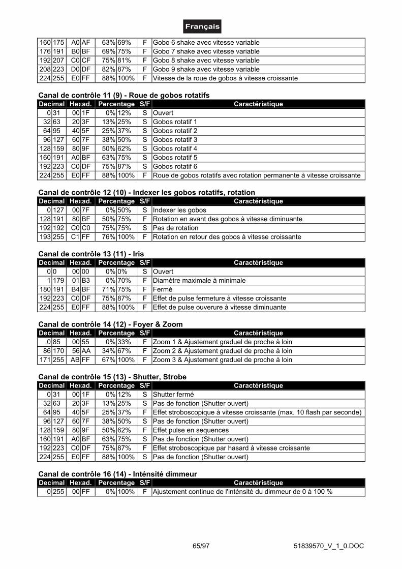
51839570_V_1_0.DOC65/97
160 175 A0 AF 63% 69% F Gobo 6 shake avec vitesse variable176 191 B0 BF 69% 75% F Gobo 7 shake avec vitesse variable192 207 C0 CF 75% 81% F Gobo 8 shake avec vitesse variable208 223 D0 DF 82% 87% F Gobo 9 shake avec vitesse variable224 255 E0 FF 88% 100% F Vitesse de la roue de gobos à vitesse croissante
Canal de contrôle 11 (9) - Roue de gobos rotatifsDecimal Hexad. Percentage S/F Caractéristique
0 31 00 1F 0% 12% S Ouvert32 63 20 3F 13% 25% S Gobos rotatif 164 95 40 5F 25% 37% S Gobos rotatif 296 127 60 7F 38% 50% S Gobos rotatif 3
128 159 80 9F 50% 62% S Gobos rotatif 4160 191 A0 BF 63% 75% S Gobos rotatif 5192 223 C0 DF 75% 87% S Gobos rotatif 6224 255 E0 FF 88% 100% F Roue de gobos rotatifs avec rotation permanente à vitesse croissante
Canal de contrôle 12 (10) - Indexer les gobos rotatifs, rotationDecimal Hexad. Percentage S/F Caractéristique
0 127 00 7F 0% 50% S Indexer les gobos128 191 80 BF 50% 75% F Rotation en avant des gobos à vitesse diminuante192 192 C0 C0 75% 75% S Pas de rotation193 255 C1 FF 76% 100% F Rotation en retour des gobos à vitesse croissante
Canal de contrôle 13 (11) - IrisDecimal Hexad. Percentage S/F Caractéristique
0 0 00 00 0% 0% S Ouvert1 179 01 B3 0% 70% F Diamètre maximale à minimale
180 191 B4 BF 71% 75% F Fermé192 223 C0 DF 75% 87% F Effet de pulse fermeture à vitesse croissante224 255 E0 FF 88% 100% F Effet de pulse ouverure à vitesse diminuante
Canal de contrôle 14 (12) - Foyer & ZoomDecimal Hexad. Percentage S/F Caractéristique
0 85 00 55 0% 33% F Zoom 1 & Ajustement graduel de proche à loin86 170 56 AA 34% 67% F Zoom 2 & Ajustement graduel de proche à loin
171 255 AB FF 67% 100% F Zoom 3 & Ajustement graduel de proche à loin
Canal de contrôle 15 (13) - Shutter, StrobeDecimal Hexad. Percentage S/F Caractéristique
0 31 00 1F 0% 12% S Shutter fermé32 63 20 3F 13% 25% S Pas de fonction (Shutter ouvert)64 95 40 5F 25% 37% F Effet stroboscopique à vitesse croissante (max. 10 flash par seconde)96 127 60 7F 38% 50% S Pas de fonction (Shutter ouvert)
128 159 80 9F 50% 62% F Effet pulse en sequences160 191 A0 BF 63% 75% S Pas de fonction (Shutter ouvert)192 223 C0 DF 75% 87% F Effet stroboscopique par hasard à vitesse croissante224 255 E0 FF 88% 100% S Pas de fonction (Shutter ouvert)
Canal de contrôle 16 (14) - Inténsité dimmeurDecimal Hexad. Percentage S/F Caractéristique
0 255 00 FF 0% 100% F Ajustement continue de l'inténsité du dimmeur de 0 à 100 %
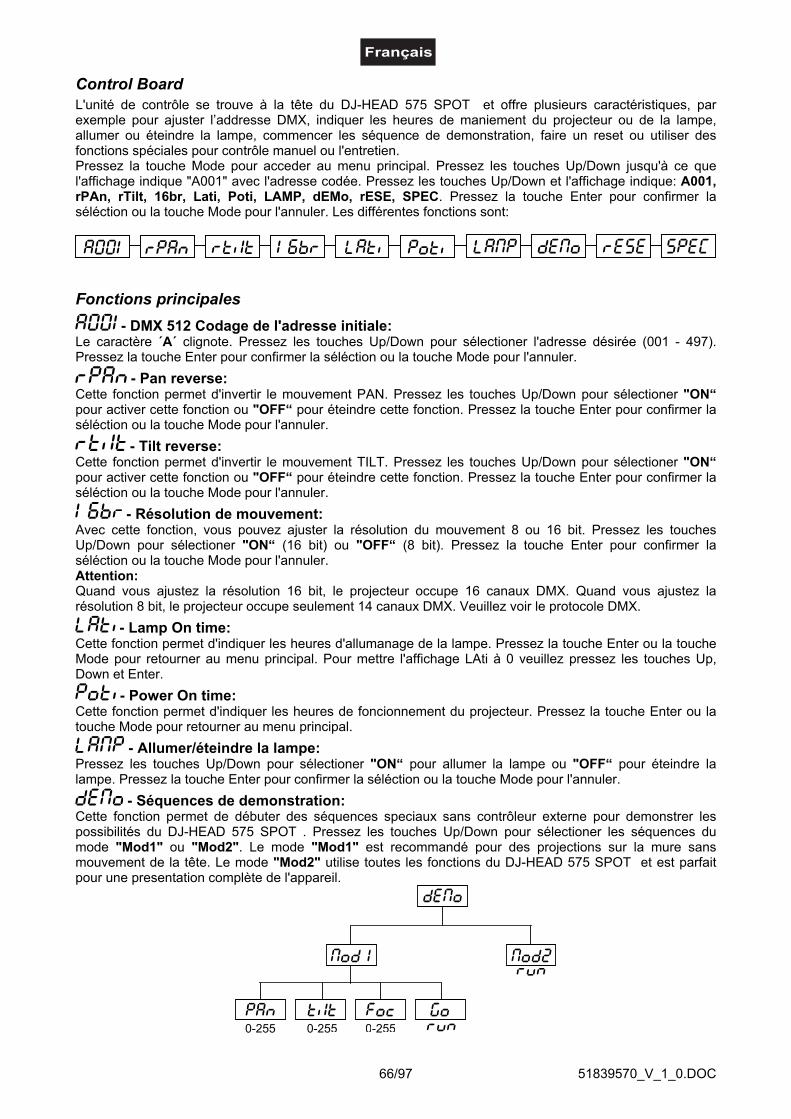
51839570_V_1_0.DOC66/97
Control BoardL'unité de contrôle se trouve à la tête du DJ-HEAD 575 SPOT et offre plusieurs caractéristiques, parexemple pour ajuster l’addresse DMX, indiquer les heures de maniement du projecteur ou de la lampe,allumer ou éteindre la lampe, commencer les séquence de demonstration, faire un reset ou utiliser desfonctions spéciales pour contrôle manuel ou l'entretien.Pressez la touche Mode pour acceder au menu principal. Pressez les touches Up/Down jusqu'à ce quel'affichage indique "A001" avec l'adresse codée. Pressez les touches Up/Down et l'affichage indique: A001,rPAn, rTilt, 16br, Lati, Poti, LAMP, dEMo, rESE, SPEC. Pressez la touche Enter pour confirmer laséléction ou la touche Mode pour l'annuler. Les différentes fonctions sont:
Fonctions principales - DMX 512 Codage de l'adresse initiale:
Le caractère ´A´ clignote. Pressez les touches Up/Down pour sélectioner l'adresse désirée (001 - 497).Pressez la touche Enter pour confirmer la séléction ou la touche Mode pour l'annuler.
- Pan reverse:Cette fonction permet d'invertir le mouvement PAN. Pressez les touches Up/Down pour sélectioner "ON“pour activer cette fonction ou "OFF“ pour éteindre cette fonction. Pressez la touche Enter pour confirmer laséléction ou la touche Mode pour l'annuler.
- Tilt reverse:Cette fonction permet d'invertir le mouvement TILT. Pressez les touches Up/Down pour sélectioner "ON“pour activer cette fonction ou "OFF“ pour éteindre cette fonction. Pressez la touche Enter pour confirmer laséléction ou la touche Mode pour l'annuler.
- Résolution de mouvement:Avec cette fonction, vous pouvez ajuster la résolution du mouvement 8 ou 16 bit. Pressez les touchesUp/Down pour sélectioner "ON“ (16 bit) ou "OFF“ (8 bit). Pressez la touche Enter pour confirmer laséléction ou la touche Mode pour l'annuler.Attention:Quand vous ajustez la résolution 16 bit, le projecteur occupe 16 canaux DMX. Quand vous ajustez larésolution 8 bit, le projecteur occupe seulement 14 canaux DMX. Veuillez voir le protocole DMX.
- Lamp On time:Cette fonction permet d'indiquer les heures d'allumanage de la lampe. Pressez la touche Enter ou la toucheMode pour retourner au menu principal. Pour mettre l'affichage LAti à 0 veuillez pressez les touches Up,Down et Enter.
- Power On time:Cette fonction permet d'indiquer les heures de foncionnement du projecteur. Pressez la touche Enter ou latouche Mode pour retourner au menu principal.
- Allumer/éteindre la lampe:Pressez les touches Up/Down pour sélectioner "ON“ pour allumer la lampe ou "OFF“ pour éteindre lalampe. Pressez la touche Enter pour confirmer la séléction ou la touche Mode pour l'annuler.
- Séquences de demonstration:Cette fonction permet de débuter des séquences speciaux sans contrôleur externe pour demonstrer lespossibilités du DJ-HEAD 575 SPOT . Pressez les touches Up/Down pour sélectioner les séquences dumode "Mod1" ou "Mod2". Le mode "Mod1" est recommandé pour des projections sur la mure sansmouvement de la tête. Le mode "Mod2" utilise toutes les fonctions du DJ-HEAD 575 SPOT et est parfaitpour une presentation complète de l'appareil.

51839570_V_1_0.DOC67/97
- Fonction reset:Pressez la touche Enter pour le débuter le reset. Toutes les fonctions et positions vont être ajustées à leurpositions standards.
SPEC - fonctions specialesPressez les touches Up/Down jusqu'à ce que l'affichage indique les différents fonctions. Pressez la toucheEnter pour confirmer la séléction.
- Contrôle manuel des effets :Cette fonction permet de contrôler les fonctions des canaux manuellement. Pressez les touches Up/Downpour sélectioner la fonction désirée. Pressez la touche Enter pour ajuster l'effet ou la touche Mode pourl'annuler.
- Allumer la lampe automatiquementGrâce à cet menu, vous pouvez ajuster la fonction allumer la lampe et desactiver le senseur de lumière.
- Allumer la lampe automatiquementCette fonction permet d'allumer la lampe automatiquement àpres d'avoir mis l'appareil enservice. Pressez les touches Up/Down pour sélectioner "ON“ pour allumer la lampeautomatiquement àpres d'avoir mis l'appareil en service ou "OFF“ si vous ne voulez pasallumer la lampe automatiquement àpres d'avoir mis l'appareil en service. Pressez la toucheEnter pour confirmer la séléction ou la touche Mode pour l'annuler.
- Activer/déactiver le senseur de lumièreCette fonction permet de déactiver le senseur de lumière. Pressez les touches Up/Down poursélectioner "ON“ pour activer le senseur de lumière ou "OFF“ si vous voulez déactiver lesenseur de lumière. Pressez la touche Enter pour confirmer la séléction ou la touche Mode pourl'annuler.Attention: L'option "OFF" est seulement prévu pour des cas cas d'urgence, par examplequand le senseur de lumière défaut et vous attendez sur les pièces de réchange. Quandle senseur de lumière est déactivé, les messages d'erreur "LAEr, SnEr, HEAt" ne sont pasaffiché ("HEAt" apparaît, mais seulement quand la lampe était éteinte et allumée dedans 5minutes.) À cause de cela, l'électronique de l'appareil continuerá d'essayer d'allumer la lampelorsque la lampe soit défecteuse ou il n'y aurait pas de lampe! Veuillez réspecter que cet actionpourraît détruire des élements électroniques.

51839570_V_1_0.DOC68/97
- valeurs DMX :Possibilité de voir tous les valeurs DMX comme reçues du contrôleur. Pressez les touches Up/Down poursélectioner le canal désiré. Pressez la touche Enter pour voir les valeurs DMX ou la touche Mode pourl'annuler.
- ajuster l'affichage:Cette fonction permet d'ajuster les valeurs de l'affichage:
- Intensité de l'affichage:Cette fonction permet d'ajuster l'intensité de l'affichage entre 20 % et 100 %. Pressez lestouches Up/Down pour sélectioner l'intensité de l'affichage. Pressez la touche Enter pourconfirmer la séléction ou la touche Mode pour l'annuler.
- Inversion de l'affichageCette fonction permet de tourner l'affichage par 180°. Pressez les touches Up/Down poursélectioner "Affichage normale“ ou "Affichage 180°“. Pressez la touche Enter pour confirmerla séléction ou la touche Mode pour l'annuler.
- Blackout automatique de l'affichageCette fonction permet de maintenir l'affichage ou de la éteindre après 2 minutes sans fonctionsur l'unité de contrôle. Pressez les touches Up/Down pour sélectioner "ON“ pour maintenirl'affichage ou "OFF“ pour le éteindre automatiquement. Pressez la touche Enter pour confirmerla séléction ou la touche Mode pour l'annuler.
- PAN/TILT-Feedback:Cette fonction permet de retourner le Moving Head à la position correcte, quand cette position a été changeéexternement, p. ex. grâce à un choc. Pressez les touches Up/Down pour sélectioner "ON“ pour retourner àla position correcte ou "OFF“ (sans fonction Feedback). Pressez la touche Enter pour confirmer la séléctionou la touche Mode pour l'annuler.Notez: Quand la fonction Feedback a été éteindue, la position PAN/TILT à été changée grâce aux forcesextérieures et la fonction Feedback à été reactivée, il est possible que l'appareil ne fonctionne passynchronement aux valeurs DMX. Dans ce cas, veuillez executer un Reset pour synchroniser l'appareil autrefois.
- Intensité de l'affichage :Cette fonction permet d'ajuster l'intensité de l'affichage entre 20 et 100. Pressez les touches Up/Down poursélectioner l'intensité de l'affichage. Pressez la touche Enter pour confirmer la séléction ou la touche Modepour l'annuler.
- Éteindre la lampe via DMX:Cette fonction permet d'éteindre la lampe via DMX. Pressez les touches Up/Down pour sélectioner "ON“pour éteindre la lampe via DMX ou "OFF“ si vous ne voulez pas éteindre la lampe via DMX. Pressez latouche Enter pour confirmer la séléction ou la touche Mode pour l'annuler.
- temperatureL'affichage indique la temperature intérieure en dégrée Celsius. Une temperature intérieure jusqu'à 80° C estnormale. Assurez-vous que la température ambiante ne dépasse pas 45° C.

51839570_V_1_0.DOC69/97
- contrôle de la vitesse du ventilateurCette fonction permet de sélectioner les 5 modes de la vitesse du ventilateur. Pressez les touches Up/Downpour sélectioner "Auto, High, reG, Lo.HI, Lo.OF". Pressez la touche Enter pour confirmer la séléction ou latouche Mode pour l'annuler.
- ajustment automatique de la vitesse du ventilateur sans contrôle DMXCe mode est identique avec "reG", mais la vitesse initiale du ventilateur ne peut pas êtrecontrôlée par DMX.
- vitesse du ventilateur maximaleLe projecteur commute le ventilateur à la vitesse maximale.
- ajustment automatique de la vitesse du ventilateurQuand la température intérieure dépasse un certain niveau, la vitesse du ventilateur augmenteautomatiquement pour contrôler la température intérieure. Cette procédure peut être répetéejusqu'à 7 fois.
- vitesse du ventilateur bas/maximale/éteindre la lampeLa vitesse du ventilateur reste bas jusqu'à la temperature intérieure surpasse le maximum.Après, le projecteur éteind la lampe automatiquement.
- vitesse du ventilateur bas/maximaleLa vitesse du ventilateur reste bas jusqu'à la temperature intérieure a augmentée au maximum.Après, le projecteur commute le ventilateur à la vitesse maximale.
Veuillez réspecter: En mode "HIGH" et "Auto", la vitesse initiale du ventilateur ne peut pas êtrecontrôlée par DMX.
- Valeurs prédéterminéesCette fonction permets de remettre à zéro toutes les données individuelles du projecteur sur la valeurprédéterminée à l’usine. Appuyez sur la touche Enter pour remettre les valeurs à zéro. Sur l‘affichage “rSt”apparaît. Svp prenez les valeurs prédéterminées individuelles du tableau en bas.
PAN-reverse
TILT-reverse
Resolution
Éteindre la lampeautomatiquement
Éteindre l'affichageautomatiquement
Intensité del'affichage
Inversion del'affichage
FonctionFeedback
Éteindre lalampe/DMX
Affichage Valeur prédé-terminée
Fonction
Contrôle duventilateur
Activer/déactiver lesenseur de lumière

51839570_V_1_0.DOC70/97
- Calibration des roues de couleurs, gobos et effets :Cette fonction permet de ce que calibrer les positions correctes des roues de couleurs, gobos et effets.Pressez les touches Up/Down jusqu'à ce que l'affichage indique les différents fonctions: "PAn, Tilt, SPEd,Colo, EFEC, Prot, rGOB, Grot, Foc, Stro, dimr, FCAL". Ces fonctions permet de ajuster l'appareil aupositions desirées (0-255) avant de commencer la fonction calibration. Après avoir ajusté les positions,utilisez la dernière fonction ´FCAL´ (Fixture calibration).
1. Calibration via l'unité de contrôlePressez la touche Enter et l'affichage indique les fonctions: "PAn, Tilt, SPEd, Col1, Col2, PriS, SGob,rGob, Grot, IriS, Foc, Stro, dimr, FCAL" pour une calibration fine. Pressez la touche Enter pour selecter lafonction désirée. Pressez les touches Up/Down pour ajuster les valeurs de 0 à 255. Pressez la touche Enterpour confirmer la séléction ou la touche Mode pour l'annuler. Cette procedure peut être répitée pour chaqueparamêtre de calibration. Après avoir ajusté les positions, utilisez la fonction ´ArES´ pour mémoriser lacalibration dans l'EEPROM et pour faire un reset. Après avoir fini le reset, l'affichage indique ´FCAL´.Pressez la touche Enter pour répeter la calibration ou la touche Mode pour retourner au menu ´AdJ´.
2. Calibration via contrôleur DMXPressez la touche Enter et l'affichage indique les fonctions: "Col1, Col2, PriS, SGob, rGob, Grot " pour unecalibration fine. Pressez la touche Enter pour selecter la fonction désirée.Vous pouvez maintenant calibrer les roues de couleurs, gobos et effets via votre contrôleur.
Protocôle de calibration DMX:
Après avoir ajusté les positions, utilisez la fonction ´ArES´ pour mémoriser la calibration dans l'EEPROM etpour faire un reset.
DMX Channel 1 2 3 4 5 6 7 8
COL.1 COL.2 SGOB RGOB GROT - COLOURS 1 COLOURS 2CALIBRATION
0 - 255CALIBRATION
0 - 255CALIBRATION
0 - 255CALIBRATION
0 - 255CALIBRATION
0 - 255-
STANDARD PROTOCOL
STANDARD PROTOCOL
DMX Channel 9 10 11 12 13 14 15 16
PRISMSTATIC GOBOS
ROTATING GOBOS
GOBO ROTATION
IRIS FOCUS STROBE DIMMER
STANDARD PROTOCOL
STANDARD PROTOCOL
STANDARD PROTOCOL
STANDARD PROTOCOL
STANDARD PROTOCOL
STANDARD PROTOCOL
STANDARD PROTOCOL
STANDARD PROTOCOL
Function
SMOOTH MICROSTEP MOVEMENT
Function

51839570_V_1_0.DOC71/97
Avis d'erreur et d'informationQuand vous mettre l'appareil en service, il fait un Reset. Quand l'affichage indique un avis d’erreur, ily a un erreur sur un ou plusieures canaux. L’avis d’erreur signifique le canal réspectif.Quand l'affichage indique p.ex. “C2Er”, ça signifique un erreur sur la roue de couleurs 2. Quand il y aautres erreurs sur canaux différents, les avis d'erreur clignote 5 fois dans l'affichage, après l'appareilfait un Reset. Quand les avis d'erreur apparaîent 3 fois, l'appareil detecte quand il y a plus de 3erreurs. Quand il y a 3 erreurs ou plus, l'appareil ne foncionne pas sans erreurs, quand il y a moinsde 3 erreurs, seulement les canaux avec erreur ne fonctionne sans erreurs.
L’avis d’erreur respectif est indiqué quand il y'a des fonctions d'erreur magnetiques (la photodiode estdéfectueuse ou le magnet manque) ou le moteur pas à pas est defectueux (ou le circuit réspectif sur laplatine principale). Le feature du canal respectif n'est pas à la position correcte.
Les avis d’erreur différents sont:
Cet avis est indiqué quand vous essayez d'allumer la lampe avant les 5 minutes après avoir mis l'appareilhors tension (la lampe est trop chaude). Cet avis apparait quand la lampe ne peut pas être allumée en 20secondes. Le DJ-HEAD 575 SPOT mémoriserá cet information et allumera la lampe automatiquementaprès les 5 minutes.Attention: Veuillez réspecter que cette fonction ne fonctionne pas si le senseur de lumière est deactivé(fonction "EnSn").
S'il n'est pas possible d'allumer la lampe 7 fois sans succès, l'affichage indiquera ´LA.Er´. Cet avis indiqueque la lampe peut être défectueuse, qu' il n' y a pas de lampe ou que la température intérieure est trop haute(p. ex. quand la température ambiante dépasse 45° C) ou que le starter ou ballast est défectueux.Veuillez remplacer la lampe ou contrôlez la température ambiante ou contactez votre revendeur si lasituation n'est pas cause par la lampe.Attention: Veuillez réspecter que cette fonction ne fonctionne pas si le senseur de lumière est deactivé(fonction "EnSn").
Cet avis est indiqué quand la communication entre platine principale et l'unité de contrôle est troublée.
Erreur à la roue de couleurs 1. Cet avis est indiqué quand il y'a des fonctions d'erreur magnetiques (laphotodiode est défectueuse ou le magnet manque) ou le moteur pas à pas est defectueux (ou le circuitréspectif sur la platine principale). La roue de couleurs n'est pas à la position correcte.
Erreur à la roue de couleurs 2. Cet avis est indiqué quand il y'a des fonctions d'erreur magnetiques (laphotodiode est défectueuse ou le magnet manque) ou le moteur pas à pas est defectueux (ou le circuitréspectif sur la platine principale). La roue de couleurs n'est pas à la position correcte.
Erreur à la roue de gobos rotatifs. Cet avis est indiqué quand il y'a des fonctions d'erreur magnetiques (laphotodiode est défectueuse ou le magnet manque) ou le moteur pas à pas est defectueux (ou le circuitréspectif sur la platine principale). La roue de gobos rotatifs n'est pas à la position correcte.
Erreur d'index sur le gobo rotatif. Cet avis est indiqué quand il y'a des fonctions d'erreur magnetiques (laphotodiode est défectueuse ou le magnet manque) ou le moteur pas à pas est defectueux (ou le circuitréspectif sur la platine principale). La gobo rotatif n'est pas à la position correcte.
Erreur à la roue de gobos statiques. Cet avis est indiqué quand il y'a des fonctions d'erreur magnetiques (laphotodiode est défectueuse ou le magnet manque) ou le moteur pas à pas est defectueux (ou le circuitréspectif sur la platine principale). La roue de gobos n'est pas à la position correcte.
Erreur à la roue du prisme. Cet avis est indiqué quand il y'a des fonctions d'erreur magnetiques (laphotodiode est défectueuse ou le magnet manque) ou le moteur pas à pas est defectueux (ou le circuitréspectif sur la platine principale). La roue du prisme n'est pas à la position correcte.
Cet avis indique que que la température intérieure était trop haute (p. ex. quand la température ambiante

51839570_V_1_0.DOC72/97
dépasse 45° C) et que le relais intérieur a coupé la lampe. Cet avis apparait jusqu' à ce que la températureredescende à un niveau acceptable. Après l'affichage indique HEAt (la lampe est trop chaude).
Cet avis indique que la diode photoelectique est défectueuse. Veuillez contactez votre revendeur.Attention: Veuillez réspecter que cette fonction ne fonctionne pas si le senseur de lumière est deactivé(fonction "EnSn").
Cet avis indique que l'appareil a été débranché brièvement.
Erreur au mouvement PAN des bras rotatifs. Cet avis est indiqué quand il y'a des fonctions d'erreurmagnetiques (la photodiode est défectueuse ou le magnet manque) ou le moteur pas à pas est defectueux(ou le circuit réspectif sur la platine principale). Les bras rotatifs ne sont pas à la position correcte.
Erreur au mouvement TILT de la tête. Cet avis est indiqué quand il y'a des fonctions d'erreur magnetiques(la photodiode est défectueuse ou le magnet manque) ou le moteur pas à pas est defectueux (ou le circuitréspectif sur la platine principale). La tête n'est pas à la position correcte.
Cet avis indique qu'il n' y a pas la tesion standard de 50 ou 60 Hz.
NETTOYAGE ET MAINTENANCEL’entrepreneur doit assurer à ce que les installations concernant la sécurité technique et la sécurité desmachines soient examinés au moins tous les quatre ans par un expert au cadre de l’épreuve de réception.
L’entrepreneur doit assurer à ce que les installations concernant la sécurité technique et la sécurité desmachines soient examinés au moins une fois par an par une personne compétente.
Entre autres, il faut respecter particulièrement les points suivants:1) Tous les vis avec lesquelles l’appareils ou des parties de l’appareil sont montés, doivent être fixément
serrées et ne doivent pas être corrodées.2) Au boîtier, aux fixations et au lieu de montage (plafond, fixations pour une installation sur un niveau
moins élevé, Traverse) aucune déformation doit être visible.3) Des parties mouvantes mécaniques comme des axes, des oeillets et similaires, ne doivent pas avoir
aucune trace d‘usure (par ex. usure par frottement ou dommages) et ne doivent pas tourner de manièredéséquilibrée.
4) Les lignes de raccord électriques ne doivent pas avoir aucun endommagement, viellissement dematériel (par ex. des lignes poreux) ou des dépôts. D’autres régulations adaptées au lieu d’utilisationrespectif et à l’utilisation, seront respectées par l’installateur compétent et des défauts de sécurité serontéliminés.
Toujours débrancher avant de proceder à l'entretien!
DANGER DE MORT!
L'appareil doit être nettoyé régulièrement de contaminations comme de la poussière etc. Pour le nettoyage,utilisez un torchon non pelucheux humide. Ne pas utiliser un aucun cas de l’alcool ou des détergents pour lenettoyage.
La lentille endommagée doit être remplacée pour que la qualitédu rayon ne soit pas amoindrie par les fissures ou rayures éventuelles!
ATTENTION!
La lentille d’objectif doit être nettoyée toutes les semaines, car des résidus de liquide de brouillard sedéposent rapidement. Nettoyer le ventilateur tous les mois.

51839570_V_1_0.DOC73/97
Ne jamais mettre l’appareil sous tension avant que le boîtierne soit refermé.
Les gobos peuvent être nettoyés à l’aide d’une brosse douce. Nettoyer l’intérieur du projecteur au moins unefois par an avec un aspirateur ou une lame d’air. Les verres colorés dichroîques, la roue de gobos et leslentilles doivent être nettoyés une fois par mois.
Pour que les paliers des gobos rotatifs fonctionnent bien, ils doivent être huilés tous les six mois. Utiliserpour cela une seringue à aiguille fine. La quantité de l’huile ne doit pas être démésurée pour éviter quel’huile n’écoule pas durant la rotation.
L'intérieur de l'appareil ne contient pas de partys nécéssitant un entretien sauf la lampe et le fusible.L'entretien et les réparations doivent être effectuées par un technicien compétent!
Veuillez faire attention aux instructions sous "Installer/Remplacer la lampe".
Remplacer le fusibleUne ampoule défectueuse peut entraîner un fusible "grillé". Toujours remplacer un fusible par un autre demodèle identique.
Avant le remplacement du fusible débrancher l'appareil.
Procédure:
Pas 1: Dévissez le porte-fusible (dans le sens inverse des aiguilles d'une montre) au dos de l'appareilavec un tournevis et le retirer du boîtier.
Pas 2: Retirez le fusible défectueux du porte-fusible.Pas 3: Installez le nouveau fusible au porte-fusible.Pas 4: Remettez le porte-fusible dans le boîtier et vissez-le.
Si des pièces de rechange sont nécéssaires, toujours utiliser des pièces d'origine.
Quand le câble secteur de cet appareil est endommagé, il doit être remplacé par un câble secteur spécialdisponible chez votre revendeur.
Pour tout renseignement complémentaire, votre revendeur se tient à votre entière disposition.

51839570_V_1_0.DOC74/97
CARACTERISTIQUES TECHNIQUES
Alimentation: 230 V AC, 50 Hz ~Puissance de rendement: 1000 WCanaux de contrôle DMX: 16Connexion DMX-512: XLR 3-pôlesFréquence des flash: 10 HzNombre de couleurs:Roue de couleurs 1: 9 dichroïques + ouvertsRoue de couleurs 2: 6 dichroïques, 2 filtres correctives, filtre UV + ouverts
64 mélanges de couleurs possiblesNombre de gobos:Roue de gobos 1: 9 gobos en métal statiques + ouvertsRoue de gobos 2: 2 gobos en métal rotatifs, 4 gobos dichroïques rotatifs +
ouvertsDiamètre extérieur des gobos: 27 mmDiamètre d'image des gobos: 23 mmLongueur de la surface de base (avec poignées): 500 mmLargeur: 475 mmHauteur (tête horizontale): 560 mmPoids (net): 35,5 kgMaximale température ambiante Ta: 45° CMaximale température du boîtier (à l'équilibre) TB: 70° CDistance minimum au surface enflammables: 0,5 mDistance minimum au object illuminé: 0,5 mFusible: T 8 A, 250 VAccessoires:GE CSR575/2 SE 95V/575W GX-9,5 1000h N° d'art. 89107000PHILIPS MSR575/2 95V/575W GX-9.5 1000h N° d'art. 89107015SYLVANIA BA575/2 SE NHR 95V/575W GX-9,5 N° d'art. 89107020OSRAM HSR 575/72 95V/575W GX-9.5 1000h N° d'art. 89107210FUTURELIGHT CP-240 contrôleur N° d'art. 51834265FUTURELIGHT CP-256/64 contrôleur 16bit N° d'art. 51834288FUTURELIGHT CP-512/64 contrôleur 16bit N° d'art. 51834295Wizard-512 USB DMX-Software + Interface N° d'art. 51860102Wizard-1024 USB DMX-Software + Interface N° d'art. 51860110FUTURELIGHT DES-3 Fiche termination 3pôle N° d'art. 51834001
Attention! Les donnés imprimée dans ce mode d’emploi sont susceptibles d’être modifiées sanspréavis. 26.04.2006 ©

51839570_V_1_0.DOC75/97
MANUAL DEL USUARIO
DJ-HEAD 575 SPOTPro-Head-Spot
¡Evite el contacto de este aparato con la lluvia y la humedad!Desconectar de la corriente antes de abrir la caja!¡
¡PRECAUCIÓN!
POR SU PROPIA SEGURIDAD, POR FAVOR LEA ESTE MANUAL DEL USUARIO DETENIDAMENTEANTES DE LA CONEXIÓN INICIAL!
Toda persona implicada en la instalación, manejo y mantenimiento de este aparato tiene que-estar cualificada-seguir las instrucciones de este manual-tratar el manual como parte del producto-mantener el manual durante la vida del producto-pasar el manual a cada sucesivo poseedor o usuario del producto-descargar la última versión del manual del Internet
INTRODUCCIÓNGracias por haber elegido un FUTURELIGHT DJ-HEAD 575 SPOT. Verá que ha adquirido un aparatopotente y versátil.
Desembale su DJ-HEAD 575 SPOT.
Inlcluido en la entraga
1 Aparato1 Manual del usuario1 Cable MC-50, 5m, negro, XLR m/f, simetr. 3022050N2 Soporte de fijación

51839570_V_1_0.DOC76/97
INSTRUCCIONES DE SEGURIDAD
¡Tenga cuidado cuando opere con este aparato. Con un voltaje peligroso puede sufriruna peligrosa descarga eléctrica al tocar los cables!
¡PRECAUCIÓN!
Este aparato ha salido de nuestro establecimiento en absolutas perfectas condiciones. Para mantener estacondición y asegurar un manejo seguro, es absolutamente necesario para el usuario seguir las instruccionesde seguridad y notas de advertencia escritas en este manual del usuario.
Importante:Los daños causados por no hacer caso de las instrucciones de este manual del usuariono están sujetos a garantía. El proveedor no aceptará responsabilidad por ningúndefecto o problema resultante.
Si el aparato ha estado expuesto a grandes cambios de temperatura (p.e. tras el transporte), no lo enchufeinmediatamente. La condensación de agua producida podría dañar su aparato. Deje el aparato desconec-tado hasta que llegue a la temperatura ambiente.
Antes de la puesta en marcha inicial, por favor asegúrese de que no hay daños causados durante eltransporte. Si el aparato u el cable están estropeado, consulte a su proveedor y no use el aparato.
Este aparato pertenece a la clase de protección I. El aparato sólo debe ser conectado con un enchufe de laclase I con voltaje y frecuencia indéntico como indicado en el aparato. Un voltaje u enchufe inapropiadopuede destruir el aparato o causar un golpe electríco mortal.
Siempre conectar la clavija de alimentación al final. La clavija debe ser insertado sin fuerza. Asegúrese deque la clavija está firmemente conectado con el enchufe.
La boquilla del cable u el conector del aparato no debe ser cargado con tracción. Siempre debe haber unalongura suficiente de cable al aparato. Otra vez, el cable puede ser estropeado que puede causar un golpeeléctrico mortal.
Preste atención que el cable de alimentación no esté aplastado o pueda estar atravesado por algún tipo desuperficie afilada. Compruebe el estado del aparato y del cable regularmente.
Cuando Vd. utilice prolongaciones, asegúrese de que el sección de los conectores está suficiente pare elcorriente del aparato. Todas las instrucciones del cable de alimentación deben ser respectadas.
Desconecte el aparato de la red cuando no vaya a ser utilizado y antes de limpiarlo. Maneje el cableúnicamente por el enchufe. No desenchufe el aparato de la red tirando del cable de alimentación. Otra vez,el cable u la clavija puede ser estropeado que puede causar un golpe electríco mortal. Si enchufes ointerruptores no son accesibles, el aparato debe ser desconectado de la red.
Desconecte el aparato de la red cuando hay polvo en la clavija u el aparato. Limpie el aparato con un pañosuave y húmedo. Polvo puede reducir la insulación que puede causar un golpe electríco mortal. Polucionesmas graves deben ser removidos por un especialista.
Líquido de todas formas deben nunca entrar en enchufes, conectores u algunos orificios del aparato.Cuando supone que líquido puede haber entrado en el aparato, desenchufe el aparato inmediatamente.También cuando el aparato se ha encontrado en un ambiente muy humedo. El aparato debe ser controladopor un especialista si insulaciones están reducidos a causa del líquido. Insulaciones reducidos puedencausar un golpe eléctrico mortal.
Piezas de todas formas deben nunca entrar en el aparato - especialmente piezas de metal. Cuando suponeque piezas de metal pueden haber entrado en el aparato, desenchufe el aparato inmediatamente.Malfunciones o cortocircuitos pueden causar un golpe eléctrico mortal.
Durante la puesta en marcha inicial puede aparecer olor o humo. Este es un proceso normal y no significanecesariamente que el aparato sea defectuoso.

51839570_V_1_0.DOC77/97
Peligro de quemadura! Nunca instalar el aparato en superficies facilmente inflamables (p.ej. tapiz de feria)!Atención: ¡No toque la caja del aparato durante su operación (la caja se caliente)!No haga efecto de flash con el aparato ya que ésto reduciría la vida de la lámpara.
¡PELIGRO PARA LA SALUD!¡No mirar directamente a la fuente de luz, las personas sensibles pueden recibir unshock epiléptico (especialmente dirigido a los epilépticos)!
Manténgalo lejos del alcance de los niños y de personal no profesional.Nunca operar el aparato sin observación.
INSTRUCCIONES DE MANEJOEste aparato es un efecto luminoso para crear efectos de decoración. El aparato sólo es permitido para unaconexión con una tensión alternativa de 230 V, 50 Hz y ha sido diseñado para ser usado en interiores.
Este aparato ha sido diseñado para usos profesionales, por ejemplo en escenas, discotecas, teatros etc.
Efectos de luz no son diseñados para un uso permanente. Considere Vd. que pausas de operaciónaumentan la vida de su aparato.
No agite el aparato. Evite la fuerza bruta al instalar y durante el manejo del aparato.
Nunca alzar el aparato por la cabeza del projector. Siempre coger el aparato por las asas de transporte.
Cuando buscar el sitio de instalación, por favor asegúrese de que el aparato no está expuesto a calorextremo, humedad o polvo. No debe haber cables mal instalados o no fijados correctamente. Asegúrese deque el aparato no puede ser tocado o tumbado. ¡Se pone usted en peligro y pone en peligro a otros!
Nunca operar o almacenar el aparato en un ambiente con agua proyectada, lluvia, humedad o humo. Altahumedad puede reducir la insulación y causar un golpe eléctrico mortal. Cuando emplear máquinas dehumo, el aparato debe ser instalado con una distancia mínima de 0,5 métros a la máquina de humo. La saladebe sólo estar saturado con humo que una visibilidad de 10 metros está garantizado.
La temperatura ambiente debe ser entre -5° C y +45° C. Mantenga el aparato alejado del sol directo(especialmente en el coche) y de fuentes de calor.
La humedad relativa no debe ser mas de 50 % en una temperatura ambiente de 45° C.
Este aparato sólo debe ser utilizado en una altura entre -20 y 2000 m arriba del mar.
Nunca operar el aparato en tormentas. Sobrevoltaje puede detruir el aparato. Siempre desconectar elaparato durante tormentas.
El símbolo - - -m incica la distancia por mínimo a objetos iluminados. La distancia entre la salida de luz yel área iluminado no debe ser menos de este valor.
Sólo instalar el aparato en superficies no inflamables. Para garantizar una bien ventilación, Vd. deberespectar un espacio de 50 cm en torno al aparato. Note por favor, que objetos sensibles a calor pueden sertransformados o dañados debido al calor emitado.
Durante el montaje del projector, el desmontaje y operaciones de mantenimiento asegúrese de que el áreadebajo del lugar de la instalación está bloquado.
Para una montaje por encima de la cabeza (altura de montaje >100 cm), siempre fije el aparato con uncable de anclaje apropriado por razones de seguridad. El cable de anclaje debe ser fijado en las fijacionesprevistas. Nunca fijar el cable de anclaje en los asas de transporte.
Cuando ponga el aparato en marcha, por favor asegúrese de que la caja está firmemente cerrada y todos

51839570_V_1_0.DOC78/97
los tornillos necesitados están atornillados.
La lámpara nunca debe ser encendida cuando el objetivo o alguna cubierta de la caja está abierta cómo aloperar lámparas de descarga hay un peligro de explosión y una radiación ultravioleta enorme que puedecausar quemaduras.
La máxima temperatura ambiente Ta = 45° C nunca debe ser excedido.
Maneje el aparato sólo después de familiarizarse con sus funciones. No permita el manejo a personas queno conocen el aparato lo suficientemente bien. La mayoría de los daños son causados por manejoinadecuado de inexpertos.
Si el aparato debe ser transportado, utilize el embalaje original para evitar daños de transporte.
¡Por favor tenga en cuenta que por razones de seguridad las modificaciones no autorizadas del aparatoestán prohibidas!
El código de barras de serie no debe ser quitado del aparato, en caso de que esto ocurra la garantía ya noes válida.
Cuando el aparato será utilizado de un modo diferente como describido en este manual, ésto puede causardaños en el producto y la garantía expira. Además todos usos diferentes pueden causar peligros como p. ej.cortocircuito, quema, descarga eléctrica, explosión de la lámpara, caída, etc.
DESCRIPCIÓN DEL APARATO
Features
DJ Moving Head potente• Sistema de colores: 2 ruedas de colores• Rueda de colores 1 con 9 filtros de color dicróico más blanco• Rueda de colores 2 con 6 filtros de color dicróico más blanco además filtros de corrección 3200 K y 6000 Ky filtro UV• Mediante los dos filtros de corrección es posible de crear hasta 64 colores y semicolores• Efecto arco iris (Rainbow) en ambas direcciones• Rueda de gobos 1 con 9 gobos estáticos y abierto• Con función "gobo shake" para los gobos estáticos• Rueda de gobos 2 giratorios con 2 gobos metálicos, 4 gobos dicróicos multicolores más abierto• Los gobos giratorios pueden ser intercambiados• Mediante la combinación de los gobos dicróicos y la rueda de color o los gobos dicróicos multicolores esposible crea incluso más combinaciones de colores• Prisma giratorio de 3 facetas con alta velocidad• Foco motorizado y controlable por distancia• Unidad de shutter/dimmer para dimmer suave y efecto flash con velocidad ajustable (1-10 flashes/seg.)• Encendido de la lámpara controlable a distancia• Función macro para la combinación de rueda de gobos giratorios y rueda de prisma giratoria• Función blackout durante movimiento de la cabeza o selección de gobo/color/prisma• Velocidad Pan/Tilt controlable a distancia para una programación fácil• Reset controlable a distancia• Reducción del ruido mediante el ajuste de la potencia del ventilador• 16 canales DMX - resolución de 16 para los movimientos del espejo• 14 canales DMX - resolución de 8 para los movimientos del espejo• Movimiento Pan dentro de 530°• Movimiento Tilt dentro de 280°• Mulit-Step zoom motorizado con tres ajustes diferentes (15°, 18° y 22°)• Iris reglable• Unidad de control con pantalla para el ajuste digital de la dirección de comienzo• Para una lámpara MSR 575/2 o MSR 575• Control DMX mediante cualquier controlador DMX standard

51839570_V_1_0.DOC79/97
Descripción de las partes
(1) Cabeza del proyector
(2) Lente
(3) Suspensión
(4) Base
(5) Asa de transporte
(6) Ventilador
(7) Interruptor de
alimentación
(8) Entrada DMX
(9) Salida DMX
(10) Alimentación/
Portafusible
(11) Sistema de lámpara
(12) LED de control
(13) Pantalla
(14) Tecla Mode
(15) Tecla Enter
(16) Tecla Down
(17) Tecla Up

51839570_V_1_0.DOC80/97
INSTALACIÓN
Instalar/Reemplazar la lámpara
¡PELIGRO DE MUERTE!¡Instale la lámpara únicamente con el aparato desenchufado!
¡Desenchufe-lo de la corriente!
Para la instalación, Vd. necesita una lámpara MSR 575/2 o MSR 575.
La lámpara debe ser cambiada únicamente con la indumentaria de protección adecuada (gafas deprotección, guantes de protección, casco con visera y delantal de cuero).
¡La lámpara debe ser reemplazada cuando esté deterioradao deformada debido al calor!
¡PRECAUCION!
No se debe exceder la vida de la lámpara dada por el fabricante. Por esta razón debe de hacer anotacionesdel tiempo de operación de la lámpara o comprobar regularmente el contador de las horas de operación ysustituir la lámpara a tiempo.
Mantener la lámpara cambiada en un contenedor protector y deshacerse de ella adecuadamente.
Al operar las lámparas de este tipo llegan a temperaturas de hasta 600° C.
Antes de reemplazar la lámpara, desenchufe-lo de la corriente y deje que la lámpara se enfrie (aprox.10 minutos).
¡Durante la instalación no toque las bombillas de cristal con las manos sin protección! ¡Por favor siga lasindicaciones del fabricante de las lámparas!
No instalar una lámpara con más vatios. Una lámpara de estas características genera temperaturas para lasque este aparato no ha sido diseñado. Los daños causados por no hacer caso a esta norma no estánsujetos a garantía.
Procedimiento:
Paso 1: Desatornille los tornillos de fijación X, Y, Z del sistema de lámpara y quitelo.Paso 2: Cuando quire reemplazar una lámpara defectuosa, primero quite la lámpara defectuosa del
casquillo.Paso 3: Coloque la lámpara en el sistema de portalámparas.Paso 4: Vuelva a colocar el sistema de lámpara y atornille los tornillos de fijación.Paso 5: Ajuste la lámpara como descrito bajo Ajuste de la lámpara.
¡No maneje este aparato con la caja abierta!

51839570_V_1_0.DOC81/97
Ajuste de la lámpara
El sistema de portalámparas está ajustado en la fábrica. Comolas lámparas de los fabricantes diferentes son diferentes, puedeser necesario de reajustar la posición del sistema deportalámparas.Enciende la lámpara, abre el shutter, coloque la intensidad deldimmer a 100 % y direccione el rayo en una superficie plana(pared). Centre el "Hot Spot" (la parte más brilliante del rayo) entornear los 3 tornillos "A, B, C". Sólo tornee un tornillo cada vezpara mover el Hot Spot en la proyección. Si no puede encontrarun Hot Spot, ajuste la lámpara hasta que la luz esté distribuidaigualmenteCuando el Hot Spot parece demasiado brilliante, puededisminuir su intensidad en mover la lámpara mas cerca al
reflector. Tornee los tornillos "A, B, C" por ¼ revolución en dirección de las agujas del reloj hasta que la luzesté distribuida igualmente.Cuando la luz parece que ser bas brilliante en el margen del rayo, la lámpara está demasiado cerca delreflector. En este caso, mueve la lámpara mas leja del reflector en tornear los tornillos "A, B, C" por ¼revolución en dirección contraria de las agujas del reloj hasta que la luz esté distribuida igualmente y el rayoparece suficientemente brilliante.
Insertar/reemplazar gobos
¡Peligro de muerte!¡Inserte los gobos únicamente con el aparato desenchufado!
¡Desenchufe-lo de la corriente!
Cuando quire otros gobos como los gobos standards, o si tiene que reemplazar algun gobo, siga lasinstrucciones debajo:
¡PRECAUCION!Nunca desatornillar los tornillos de los gobos giratorios,
porque Vd. abre los rodamientos de bolas!
Quite el anillo opresor con un útil apropriado. Quite el gobo y inserte el nuevo gobo. Inserte el anillo opresoren el gobo.
Note por favor!Sistema Slot in de gobo para cambio los gobos sim utensilio.
porque Vd. abre los rodamientos de bolas!

51839570_V_1_0.DOC82/97
Montaje del proyector
¡PELIGRO DE MUERTE!Cuando instalar el aparato, Vd. debe considerar las instrucciones de EN 60598-2-17 y de
las normas nacionales respectivas. ¡La instalación sólo debe ser efectuada por un
distribuidor autorisado!
La suspensión del proyector debe ser fabricado de una manera que puede llevar 10 vezes la carga por unahora sin sufrir deformaciones dañosas permanentes.
La instalación siempre debe ser efectuada con una segunda suspensión independiente, por ejemplo una redde anclaje apropriada. Esta segunda suspensión debe ser fabricado y fijado de una manera que no parte dela instalación puede cairse en el caso de defecto de la suspensión principal.
Durante el montaje del projector, el desmontaje y operaciones de mantenimiento la presencia en áreas demovimiento, en puentes de iluminación, debajo de puestos de trabajo altos y otros áreas de peligro espermitida.
El empresario debe asegurar que instalaciones de seguridad y de máquinas son inspeccionados por unperito antes de la primera puesta en marcha y antes de otra puesta en marcha después de cambios graves.
El empresario debe asegurar que instalaciones de seguridad y de máquinas son inspeccionados por unperito en la extension de una inspección inicial cada cuatro años por lo menos.
El empresario debe asegurar que instalaciones de seguridad y de máquinas son inspeccionados por unbaquiano una vez por año.
Procedimiento:El proyector debe ser instalado fuera de áreas dónde personas pueden entretenerse.
IMPORTANTE! UNA MONTAJE POR ENCIMA DE LA CABEZA REQUIERA MUCHA EXPERIENCIA. Éstoincluye (pero no es limitadoa) calculaciones de la capacidad de carga, material de instalación usado yinspecciones regulares del material usado y del proyector. Nunca trate de instalar el proyector su mismo sino tiene estas qualificaciones pero llame un instalador profesional. Instalaciones inadecuadas puedencausar daños de hombres y/o de propiedad.
El proyector debe ser instalado fuera de dónde personas pueden llegarlo con sus manos.
Cuando quiere abajar el proyector del techo o portadores altos, siempre debe utilisar sistemas de trussing.El proyector nunca debe ser instalado pendiendo libremente en el espacio.
Atención: ¡En caso de caída, proyectores pueden causar daños cuantiosos! ¡Cuando tiene dudas en laseguridad de una forma de instalación, NO instale el proyector!
Asegúrese antes de la montaje, que el área de montaje puede llevar una carga de punto de un mínimo de10 veces del peso del proyector.
Al instalar el aparato asegúrese de que no hay ningún material altamenteinflamable (artículos de decoración, etc.) a una distancia mínima de 0,5 m.
¡PELIGRO DE INCENDIO!
¡PRECAUCION!Sólo monte el projector mediante dos ágrafes adecuadas. Por favor
dirijase a las explicaciones en la parte inferior de la base.Asegúrese de que el aparato esté fijado seguramente.
Asegúrese de que la fijación esté stable.

51839570_V_1_0.DOC83/97
El aparato puede ser colocado directamente en el suelo o puede ser instalado en cualquier posición en eltrussing sin alterar sus características operativas.
La base del proyector puede ser instalada en 2 modos diferentes.
Para una montaje por encima de la cabeza (altura de montaje >100 cm), siempre segure el proyector con uncable de anclaje, que puede llevar 12 veces más del peso del aparato. Sólo debe utilisar un cable de anclajecon eslabón de conexión roscado. Insere el cable de anclaje en el orificio en la base y en el trussing u unlugar de fijación seguro. Insere el final en el eslabón de conexión roscado y fije el tornillo de fijación.
La distancia máxima de caida es 20 cm.
Un cable de anclaje ya utilizado u estropeado nunca debe ser utilizado otra vez.
¡PELIGRO DE MUERTE!¡Antes de la primera puesta en marcha, la instalación debe ser inspeccionada por un perito!
Atornille el agrafe con un tornillo M12 con los soportes de fijación.Insere los sujetadores Quick-Lock del soporte de fijación en los orificios de la parte inferior del aparato.Fijar los sujetadores Quick-Lock. Instale el segundo soporte de fijación.
Insere el cable de anclaje en el orificio en la base y en el trussing u un lugar de fijación seguro. Insere elfinal en la carabina y fije el tornillo de seguridad.
Conexión al controlador DMX / conexión proyector - proyector

51839570_V_1_0.DOC84/97
Asegúrese de que los conductores del cable de datos no hagancontacto entre si. Los aparatos no van a funcionar o no van
a funcionar correctamente.
Note por favor que la dirección de comienzo es independiente del controlador usado.Por favor, lee el manual del usuario del controlador usado.
Sólo es válido cuando la lámpara está apagado mediante DMX.
La conexión entre controlador y proyector y entre proyector y proyector se tiene que efectuar con un cablede dos polos con blindaje. La conexión se efectua mediante clavijas y conectores XLR tripolares.
La ocupación de la conexión XLR es:
Cuando Vd. utilice los controladores con la ocupación descrita, puede conectar la salida DMX delcontrolador directamente con la entrada DMX del primer aparato de la cadena DMX. Cuando Vd. quiereconectar controladores DMX con otros salidas DMX, se tiene que utilizar cables de adaptación.
Instalación de una cadena DMX:Conecte la salida DMX del primero aparato de la cadena con la entrada DMX del próximo aparato. Siempreconecte una salida con una entrada del próximo aparato hasta que todos los aparatos están conectados.
Atención: En el ultimo proyector, la conexión DMX tiene que ser terminada con un resistor de terminación.Solde un resistor de 120 ohmios en una clavija XLR entre la señal (-) y la señal (+) y enchufe-la en la salidaDMX del ulterior aparato.
AlimentaciónConectar el aparato a la red mediante el cable de alimentación incluído.
La ocupación de los cables de conexión es:
Cable Pin InternacionalMarrón Fase LAzul Neutro NAmarillo/Verde Tierra
La tierra debe ser conectada.
Cuando Vd. quire instalar el aparato directamente a la red local, Vd. debe instalar un interruptor de la redcon una apertura de 3 mm por mínimo en cada polo.
Sólo conectar el aparato a una instalación eléctrica conforme a las regulaciones IEC. Esta instalación debeser equipada con un disyuntor de corriente residual (RCD) con un máximo corriente residual de 30 mA.
Efectos de luz no deben ser conectados a dimming-packs.

51839570_V_1_0.DOC85/97
OPERACIÓNTras la conexión del aparato a la red, el DJ-HEAD 575 SPOT comienza a funcionar. Durante el Reset, losmotores se ajustan y el aparato está listo para ser usado después.
Operación Stand AloneEn el modo Stand Alone, Vd. puede utilizar el DJ-HEAD 575 SPOT sin controlador.Desconecte el DJ-HEAD 575 SPOT del controlador y llama el programa integrado:
Para editar el programa integrado sigue las instrucciones bajo Control Board.
Control por DMXVd. puede controlar los proyectores individuales mediante su controlador DMX. Cada canal DMX tiene otraocupación con caracteristicas diferentes. Vd. puede ver los canales individuales y sus características bajoProtócolo DMX.
Direccionamiento del proyectorVd. puede ajustar la dirección de comienzo mediante la unidad de control. La dirección de comienzo es elprimer canal en lo cual el proyector reaccionará a señales del controlador.Por ejemplo, si Vd. ajuste la dirección de comienzo a 17, el proyector ocupa los canales 17 hasta 32.Por favor, asegúrese de que los canales de control no se entrelazan, para que el DJ-HEAD 575 SPOTfuncione correctamente y independientemente de otros aparatos de la cadena DMX.Los proyectores con la misma dirección de comienzo funcionarán sincronizadamente.
Procedimiento:1. Conecte el DJ-HEAD 575 SPOT y espere hasta que el aparato haya terminado la reinicialización("Setup") ("rSt" parpadea en la pantalla).2. Pulse la tecla Mode para entrar en el menú principal. Vd. puede moverse en el menú mediante las teclasUp/Down hasta que la pantalla muestre "A001". Confirme la selección con la tecla Enter y la letra "A"comienza a parpadear.3. Pulse las teclas Up/Down para seleccionar la dirección de comienzo deseada. Pulse la tecla4. Enter para confirmar o la tecla Mode para cancelar.
Control:Después de ajustar la dirección de comienzo, Vd. puede controlar el DJ-HEAD 575 SPOT mediante sucontrolador DMX.
Note:El aparato indica los modos de datos DMX-512 y de la lámpara mediante la pantalla:
Conecte el aparato. El aparato controla si recibe datos DMX-512 o no. Si recibe datos, la pantalla muestra"A001" con la dirección de comienzo ajustada. Si no recibe datos, la pantalla parpadea.El aviso aparece-si no cable XLR (cable de señal del controlador) habia sido puesto en la entrada DMX del aparato.-si el controlador está desconectado o defecuoso.-el cable o la clavija esta defectuoso o el cable de señal no está conectado correctamente.
Atención: En el ulterior proyector, la cadena DMX tiene que ser terminada con un resistor de terminaciónpara que los aparatos funcionen correctamente.

51839570_V_1_0.DOC86/97
Protócolo DMX resolución 16 Bit (resolución 8 Bit)
Canal de control 1 (1) - Movimiento horizontal (Pan) (dentro de un ángulo de 530°)Establezca los ajustes para mover la cabeza horizontalmente (PAN).Los movimientos graduales de la cabeza mediante el ajuste lento de los valores DMX (0-255; 128 = centro).Vd. puede parar la cabeza en cada posición.
Canal de control 2 (2) - Movimiento vertical (Tilt) (dentro de un ángulo de 280°)Establezca los ajustes para mover la cabeza verticalmente (TILT).Los movimientos graduales de la cabeza mediante el ajuste lento de los valores DMX (0-255; 128 = centro).Vd. puede parar la cabeza en cada posición.
Canal de control 3 - Movimiento Pan con resolución 16 Bit
Canal de control 4 - Movimiento Tilt con resolución 16 Bit
Canal de control 5 (3) - Velocidad del movimiento Pan/TiltDecimal Hexad. Percentage S/F Característica
0 0 00 00 0% 0% S Velocidad máxima (Modo de Tracking)1 249 01 F9 0% 98% F Velocidad decreciente (Modo de Vector)
250 252 FA FC 98% 99% S Velocidad máxima (Modo de Tracking), Blackout con cambio del coloro del gobo
253 255 FD FF 99% 100% S Velocidad máxima (Modo de Tracking), Blackout con movimientoPan/Tilt y cambio del color/gobo
Canal de control 6 (4) - Lámpara, reset, ventiladorDecimal Hexad. Percentage S/F Característica
0 127 00 7F 0% 50% F Ventilador en velocidad decreciente128 139 80 8B 50% 55% S Encender la lámpara, reset, abierto140 229 8C E5 55% 90% S No función230 239 E6 EF 90% 94% S La lámpara está apagada después de 3 segondos240 255 F0 FF 94% 100% S No función
Canal de control 7 (5) - Rueda de colores 1Cambio linear de los colores mediante el ajuste de los valores DMX.Puede parar la rueda de colores en cualquier posición que desee. También puede para entre dos coloresy crear rayos de dos colores.Entre los valores DMX 128 y 190 y entre 194 y 255, la rueda de colores está girando continuamente - elefecto arco iris (Rainbow) està creado.Decimal Hexad. Percentage S/F Característica
0 12 00 0C 0% 5% S Abierto/blanco13 25 0D 19 5% 10% S Azul claro26 37 1A 25 10% 15% S Rojo38 50 26 32 15% 20% S Azul51 63 33 3F 20% 25% S Verde claro64 76 40 4C 25% 30% S Amarillo77 89 4D 59 30% 35% S Magenta90 101 5A 65 35% 40% S Cyan
102 114 66 72 40% 45% S Verde115 127 73 7F 45% 50% S Naranja128 190 80 BE 50% 75% F Efecto arco iris hacia adelante con velocidad decreciente191 193 BF C1 75% 76% S No rotación194 255 C2 FF 76% 100% F Efecto arco iris hacia atrás con velocidad creciente
0 255 00 FF 0% 100% S Función macro de colores (canal 8 entre 128-255) - 64 coloresdiferentes: blanco, pink, magenta, rojo, naranja, amarillo, verde, cyan,azul, UV

51839570_V_1_0.DOC87/97
Canal de control 8 (6) - Rueda de colores 2Decimal Hexad. Percentage S/F Característica
0 11 00 0B 0% 4% S Blanco12 23 0C 17 5% 9% S Rojo oscuro24 35 18 23 9% 14% S Azul oscuro36 47 24 2F 14% 18% S Pink48 59 30 3B 19% 23% S Cyan60 71 3C 47 24% 28% S Magenta72 83 48 53 28% 33% S Amarillo84 95 54 5F 33% 37% S Filtro correctivo 6000 K96 107 60 6B 38% 42% S Filtro correctivo 3200 K
108 119 6C 77 42% 47% S Filtro UV120 127 78 7F 47% 50% S Blanco128 255 80 FF 50% 100% S Activar la función macro del canal 7
Canal de control 9 (7) - Prisma giratorio de 3 facetas, macrosDecimal Hexad. Percentage S/F Característica
0 0 00 00 0% 0% S Abierto1 63 01 3F 0% 25% F Rotación hacia adelante con velocidad decreciente
64 64 40 40 25% 25% S No rotación65 127 41 7F 25% 50% F Rotación hacia atrás con velocidad creciente
128 135 80 87 50% 53% S Macro 1136 143 88 8F 53% 56% S Macro 2144 151 90 97 56% 59% S Macro 3152 159 98 9F 60% 62% S Macro 4160 167 A0 A7 63% 65% S Macro 5168 175 A8 AF 66% 69% S Macro 6176 183 B0 B7 69% 72% S Macro 7184 191 B8 BF 72% 75% S Macro 8192 199 C0 C7 75% 78% S Macro 9200 207 C8 CF 78% 81% S Macro 10208 215 D0 D7 82% 84% S Macro 11216 223 D8 DF 85% 87% S Macro 12224 231 E0 E7 88% 91% S Macro 13232 239 E8 EF 91% 94% S Macro 14240 247 F0 F7 94% 97% S Macro 15248 255 F8 FF 97% 100% S Macro 16
Canal de control 10 (8) - Rueda de gobos estáticos, gobo shakeDecimal Hexad. Percentage S/F Característica
0 7 00 07 0% 3% S Abierto8 15 08 0F 3% 6% S Gobo 1
16 23 10 17 6% 9% S Gobo 224 31 18 1F 9% 12% S Gobo 332 39 20 27 13% 15% S Gobo 440 47 28 2F 16% 18% S Gobo 548 55 30 37 19% 22% S Gobo 656 63 38 3F 22% 25% S Gobo 764 71 40 47 25% 28% S Gobo 872 79 48 4F 28% 31% S Gobo 980 95 50 5F 31% 37% F Gobo 1 shake con velocidad variable96 111 60 6F 38% 44% F Gobo 2 shake con velocidad variable
112 127 70 7F 44% 50% F Gobo 3 shake con velocidad variable128 143 80 8F 50% 56% F Gobo 4 shake con velocidad variable144 159 90 9F 56% 62% F Gobo 5 shake con velocidad variable

51839570_V_1_0.DOC88/97
160 175 A0 AF 63% 69% F Gobo 6 shake con velocidad variable176 191 B0 BF 69% 75% F Gobo 7 shake con velocidad variable192 207 C0 CF 75% 81% F Gobo 8 shake con velocidad variable208 223 D0 DF 82% 87% F Gobo 9 shake con velocidad variable224 255 E0 FF 88% 100% F Rotación de los gobos con velocidad creciente
Canal de control 11 (9) - Rueda de gobos giratoriosDecimal Hexad. Percentage S/F Característica
0 31 00 1F 0% 12% S Abierto32 63 20 3F 13% 25% S Gobo giratorio164 95 40 5F 25% 37% S Gobo giratorio296 127 60 7F 38% 50% S Gobo giratorio3
128 159 80 9F 50% 62% S Gobo giratorio4160 191 A0 BF 63% 75% S Gobo giratorio5192 223 C0 DF 75% 87% S Gobo giratorio6224 255 E0 FF 88% 100% F Rueda de gobos girando con rotación permanente con velocidad
creciente
Canal de control 12 (10) - Indicación de gobos giratorios, rotación de gobosDecimal Hexad. Percentage S/F Característica
0 127 00 7F 0% 50% S Indicación de los gobos giratorios128 191 80 BF 50% 75% F Rotación de los gobos hacia adelante con velocidad decreciente192 192 C0 C0 75% 75% S No rotación193 255 C1 FF 76% 100% F Rotación de los gobos hacia atrás con velocidad creciente
Canal de control 13 (11) - IrisDecimal Hexad. Percentage S/F Característica
0 0 00 00 0% 0% S Abierto1 179 01 B3 0% 70% F Diámetro máximo hasta mínimo
180 191 B4 BF 71% 75% F Cerrado192 223 C0 DF 75% 87% F Efecto puls abriendo con velocidad creciente224 255 E0 FF 88% 100% F Efecto puls cerrando con velocidad decreciente
Canal de control 14 (12) - Foco & ZoomDecimal Hexad. Percentage S/F Característica
0 85 00 55 0% 33% F Zoom 1 & Ajuste gradual de cerca hasta lejos86 170 56 AA 34% 67% F Zoom 2 & Ajuste gradual de cerca hasta lejos
171 255 AB FF 67% 100% F Zoom 3 & Ajuste gradual de cerca hasta lejos
Canal de control 15 (13) - Shutter, StrobeDecimal Hexad. Percentage S/F Característica
0 31 00 1F 0% 12% S Shutter cerrado32 63 20 3F 13% 25% S No función (Shutter abierto)64 95 40 5F 25% 37% F Efecto flash con velocidad creciente (10 flashes/segondo como
máximo)96 127 60 7F 38% 50% S No función (Shutter abierto)
128 159 80 9F 50% 62% F Efecto de impulso en secuencias160 191 A0 BF 63% 75% S No función (Shutter abierto)192 223 C0 DF 75% 87% F Efecto flash mediante función aleatoria con velocidad creciente224 255 E0 FF 88% 100% S No función (Shutter abierto)
Canal de control 16 (14) - Intensidad del dimmerDecimal Hexad. Percentage S/F Característica
0 255 00 FF 0% 100% F Ajuste gradual de la intensidad del dimmer desde 0 hasta 100 %

51839570_V_1_0.DOC89/97
Control BoardLa unidad de control se encuentra en la cabeza y ofrece varias posibilidades. Por ejemplo, Vd. puedeajustar la dirección de comienzo, leer las horas de servicio del aparato y de la lámpara, encender y apagarla lámpara, comenzar el programa de demonstración o un Reset. Además, Vd. puede llamar funcionesespeciales para control manuel y servicio.Pulse la tecla Mode para entrar en el menú principal. Vd. puede moverse en el menú mediante las teclasUp/Down.En la pantalla aparece: A001, rPAn, rTilt, 16br, Lati, Poti, LAMP, dEMo, rESE, SPECConfirme la selección deseada con la tecla Enter. Las funciones son descritas en la parte siguiente.
Funciones principales - Ajustar la dirección de comienzo DMX-512:
La letra "A" parpadea. Pulse las teclas Up/Down para ajustar la dirección de comienzo (001-512) deseada.Pulse la tecla Enter para confirmar o la tecla Mode para cancelar.
- Inversion del movimiento Pan:Con esta función, Vd. puede invertir el movimiento Pan. Pulse las teclas Up/Down para ajustar "ON" u"OFF". Pulse la tecla Enter para confirmar o la tecla Mode para cancelar.
- Inversion del movimientoTilt:Con esta función, Vd. puede invertir el movimiento Tilt. Pulse las teclas Up/Down para ajustar "ON" u"OFF". Pulse la tecla Enter para confirmar o la tecla Mode para cancelar.
- Resolución del movimiento:Con esta función, Vd. puede conmutar la resolución del movimiento de la cabeza de 8 a 16 bits. Pulse lasteclas Up/Down para ajustar "ON" (16 bits) u "OFF" (8 bits). Pulse la tecla Enter para confirmar o la teclaMode para cancelar.Atención:Cuando Vd. conmute el proyector a 16 bits, el aparato ocupará 16 canales DMX. Cuando el proyector estáajustado a 8 bits, sólo ocupará 14 canales DMX. Por favor, informese de los canales DMX bajo "ProtocoloDMX".
- Horas de servicio de la lámpara:Con esta función, Vd. puede comprobar las horas de servicio de la lámpara. Pulse la tecla Enter o la teclaMode para regresar al ménu principal. Para reajustar las horas de servicio de la lámpara a 0, mantenerpresionados a la vez las teclas Up/Down y la tecla Enter.
- Contador de la horas de servicio:Con esta función, Vd. puede comprobar las horas de servicio del proyector. Pulse la tecla Enter o la teclaMode para regresar al ménu principal.
- Encender la lámpara:Con esta función, Vd. puede encender y apagar la lámpara. Pulse las teclas Up/Down para ajustar "ON"(lámpara encendida) u "OFF" (lámpara apagada). Pulse la tecla Enter para confirmar o la tecla Mode paracancelar.
- Programa de demonstración:Con esta función, Vd. puede iniciar el programa de demonstración. De esta manera, Vd. puede presentaralgunas de la posibilidades del DJ-HEAD 575 SPOT sin controlador exterior. Pulse las teclas Up/Down paraseleccionar las secuencias "Mod1" o "Mod2". La secuencias bajo "Mod1" son ideales para proyecciones enla pared, el techo o el suelo sin movimiento de la cabeza. Las secuencias bajo "Mod2" muestran todas lasfunciones del proyector y son perfectas para presentaciones del producto.

51839570_V_1_0.DOC90/97
- Ejecutar un Reset:Pulse la tecla Enter para ejecutar un Reset. De esta manera, los motores son equilibrados en un reajuste.
SPEC - Funciones especialesVd. puede moverse en el menú mediante las teclas Up/Down y seleccionar la función deseada mediante latecla Enter.
- Control manual:Con esta función, Vd. puede controlar el proyector manualmente. Pulse las teclas Up/Down para seleccionarla función deseada. Pulse la tecla Enter para confirmar o la tecla Mode para cancelar.
- Encender la lámpara automaticamenteMediante este menu, Vd. puede ajustar la función encender la lámpara y activar/desactivar el sensor de luz.
- Encender la lámpara automaticamenteCon esta función, Vd. puede programar el aparato de esta manera que la lámpara estáencendido des que Vd. apaga el aparato. Si Vd. quire que la lámpara está encendidoautomaticament, pulse las las teclas Up/Down para seleccionar "ON" u "OFF" para que lalámpara esté apagado. Pulse la tecla Enter para confirmar o la tecla Mode para cancelar.
- activar/desactivar el sensor de luzCon esta función, Vd. puede desactivar el sonsor de luz. Si Vd. quire desactivar el sonsor deluz, pulse las las teclas Up/Down para seleccionar "ON" u "OFF" para desactivar el sonsor deluz. Pulse la tecla Enter para confirmar o la tecla Mode para cancelar.¡Atención: La opción "OFF" es sólo prevista para casos de necesidad, por ejemplocuando el sensor de luz está roto y Vd. está esperando en las piezas de recambio.Cuando el sensor de luz está desactivado, los avisos de error "LAEr, SnEr, HEAt" no aparecenen la pantalla ("HEAt" aparece cuando la lámpara está desapagado e encendido dentro decinco minutos). Por eso, la electrónica del aparato continuara encender la lámpara, tambiíencuando la lámpara está roto o no hay ningún lámpara dentro del aparato. Por favor, note queeste proceso también puede estropear elementos electrónicos.

51839570_V_1_0.DOC91/97
- valores DMX:Con esta función, Vd. puede comprobar el valor DMX actual de cada canal. Pulse las teclas Up/Down paraseleccionar el canal deseado. Pulse la tecla Enter para comprobar el valor o la tecla Mode para cancelar.
- Ajustar la pantalla:Con esta función, Vd. puede ajustar los modos diferentes de la pantalla:
- Iluminación de la pantallaCon esta función, Vd. puede ajustar la intensidad de la iluminación de la pantalla entre 20 % y100 %. Pulse las teclas Up/Down para ajustar la intensidad deseada. Pulse la tecla Enter paraconfirmar o la tecla Mode para cancelar.
- Inversión de la pantallaCon esta función, Vd. puede invertir la pantalla por 180°. Pulse las teclas Up/Down paraseleccionar "Pantalla normal" o "Pantalla invertida por 180°". Pulse la tecla Enter paraconfirmar o la tecla Mode para cancelar.
- Apagar la pantalla automaticamenteCon esta función, Vd. puede ajustar que el aparato apagará la pantalla automaticamentedespués de 2 minutos sin presión en alguna tecla. Pulse las teclas Up/Down para seleccionar"ON" u "OFF". Pulse la tecla Enter para confirmar o la tecla Mode para cancelar.
- PAN/TILT-Feedback:Con esta función, Vd. puede regresar el Moving Head en la posición correcta después de está posición hasido cambiada externamente, p. ej. por un golpe etc. Pulse las teclas Up/Down para seleccionar "ON"(regresar en la posición correcta) u "OFF" (sin función Feedback). Pulse la tecla Enter para confirmar o latecla Mode para cancelar.Atención: Cuando la función Feedback ha sido apagada, la posición PAN/TILT ha sido cambiado porfuerzas externas y la función Feedback ha sido reactivada pued ser que el aparato no trabajasincrónicamente con los valores DMX. En este caso ejecute un Reset para sincronizar el aparato.
- Apagar la lámpara mediante DMX:Con esta función, Vd. puede apagar la lámpara mediante DMX. Pulse las teclas Up/Down para seleccionar"ON" (apagar la lámpara mediante DMX) u "OFF" (no apagar la lámpara mediante DMX). Pulse la teclaEnter para confirmar o la tecla Mode para cancelar.
- TemperaturaCon esta función, Vd. puede comprobar la temperatura interna del proyector en degrados Celsius. Latemperatura de trabajonormal debe ser bajo de 80° C. 80° C o mas ya están críticos y provocan el apagamiento del proyector. Porfavor, atende a que la temperatura ambiente no debe ser mas de 45° C para asegurar un enfriamientosuficiente.
- Ajuste de la velocidad del ventiladorCon esta función, Vd. puede ajustar la velocidad del ventilador mediante cinco modos diferentes. Pulse lasteclas Up/Down para seleccionar el modo deseado "Auto, High, reG", "Lo.OF" o "Lo.HI". Pulse la teclaEnter para confirmar o la tecla Mode para cancelar.
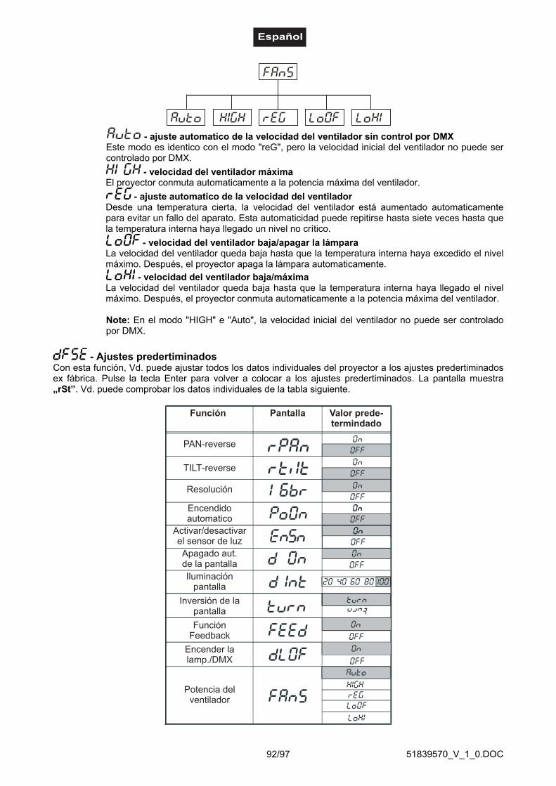
51839570_V_1_0.DOC92/97
- ajuste automatico de la velocidad del ventilador sin control por DMXEste modo es identico con el modo "reG", pero la velocidad inicial del ventilador no puede sercontrolado por DMX.
- velocidad del ventilador máximaEl proyector conmuta automaticamente a la potencia máxima del ventilador.
- ajuste automatico de la velocidad del ventiladorDesde una temperatura cierta, la velocidad del ventilador está aumentado automaticamentepara evitar un fallo del aparato. Esta automaticidad puede repitirse hasta siete veces hasta quela temperatura interna haya llegado un nivel no crítico.
- velocidad del ventilador baja/apagar la lámparaLa velocidad del ventilador queda baja hasta que la temperatura interna haya excedido el nivelmáximo. Después, el proyector apaga la lámpara automaticamente.
- velocidad del ventilador baja/máximaLa velocidad del ventilador queda baja hasta que la temperatura interna haya llegado el nivelmáximo. Después, el proyector conmuta automaticamente a la potencia máxima del ventilador.
Note: En el modo "HIGH" e "Auto", la velocidad inicial del ventilador no puede ser controladopor DMX.
- Ajustes predertiminadosCon esta función, Vd. puede ajustar todos los datos individuales del proyector a los ajustes predertiminadosex fábrica. Pulse la tecla Enter para volver a colocar a los ajustes predertiminados. La pantalla muestra„rSt”. Vd. puede comprobar los datos individuales de la tabla siguiente.
PAN-reverse
TILT-reverse
Resolución
Encendidoautomatico
Apagado aut.de la pantallaIluminación
pantalla
Inversión de lapantalla
FunciónFeedback
Encender lalamp./DMX
Pantalla Valor prede-termindado
Función
Potencia delventilador
Activar/desactivarel sensor de luz

51839570_V_1_0.DOC93/97
- Ajustar la posiciones predertiminadas:Con esta función, Vd. puede calibrar las posiciones predertiminadas de las ruedas de colores, de gobos yde la prisma en las posiciones correctas. Pulse las teclas Up/Down para moverse en el ménu. La pantallamuestra las funciones "PAn, Tilt, SPEd, Colo, EFEC, Prot, rGOB, Grot, Foc, Stro, dimr, FCAL". Vd.puede ajustar estas funciones en la posición deseada (0-255) antes des calibrar. Después de haber entradolas posiciones, seleccione la última función "FCAL" y el aparato será calibrado.
1. Calibrado mediante la unidad de controlPulse la tecla Enter y en pulsar la teclas Up/Down la pantalla muestra "PAn, Tilt, SPEd, Col1, Col2, PriS,SGob, rGob, Grot, IriS, Foc, Stro, dimr, FCAL" para un calibrado muy suave. Seleccione una de estasfunciones mediante la tecla Enter para ajustar la posición correcta entre 0 y 255. Pulse la tecla Enter paraconfirmar o la tecla Mode para cancelar. Este procedimiento puede ser repitido para cada parámetro decalibrado. Después de haber ajustado todos los parámetros de calibrado, Vd. tiene que seleccionar lafunción "ArES" para transmitir los valores ajustados en el EEPROM y para ejecutar un Reset. Después dehaber terminado el Reset, la pantalla muestra "FCAL". Pulse la tecla Enter para repitir el calibrado o la teclaMode para regresar al ménu "AdJ".
2. Calibrado mediante el controlador externoPulse la tecla Enter y en pulsar la teclas Up/Down la pantalla muestra "Col1, Col2, PriS, SGob, rGob, Grot" para un calibrado muy suave. Seleccione una de estas funciones mediante la tecla Enter. Ahora puedecalibrar las ruedas diferentes mediante su controlador. El protocolo de calibrado está mencionado abajo.
Protocolo de calibrado:
Después de haber ajustado los parámetros de calibrado deseados y de haber confirmarlos con la teclaEnter, Vd. tiene que seleccionar la función "ArES" para transmitir los valores ajustados en el EEPROM ypara ejecutar un Reset.
DMX Channel 1 2 3 4 5 6 7 8
COL.1 COL.2 SGOB RGOB GROT - COLOURS 1 COLOURS 2CALIBRATION
0 - 255CALIBRATION
0 - 255CALIBRATION
0 - 255CALIBRATION
0 - 255CALIBRATION
0 - 255-
STANDARD PROTOCOL
STANDARD PROTOCOL
DMX Channel 9 10 11 12 13 14 15 16
PRISMSTATIC GOBOS
ROTATING GOBOS
GOBO ROTATION
IRIS FOCUS STROBE DIMMER
STANDARD PROTOCOL
STANDARD PROTOCOL
STANDARD PROTOCOL
STANDARD PROTOCOL
STANDARD PROTOCOL
STANDARD PROTOCOL
STANDARD PROTOCOL
STANDARD PROTOCOL
Function
SMOOTH MICROSTEP MOVEMENT
Function

51839570_V_1_0.DOC94/97
Avisos de errorCuando Vd. pone el aparato en servicio, hace un Reset. Cuando la pantalla muestra un aviso deerror, hay un error en un o mas canales. El aviso de error respectivo significa el canalcorrespondiente.Cuando la pantalla muestra por ejemplo “C2Er” significa un error en la rueda de colores 2. Si hay unerror en algunos canales al mismo tiempo, los avisos de error parpadean 5 veces en la pantalla,después el aparato hace un Reset. Cuando los avisos de error aparecen otro 3 veces, el aparatodetectara si hay mas de 3 errores. Cuando hay 3 errores o mas, el aparato no funciona sin error.Cuando hay menos de 3 errores, sólo los canales con los errores no funcionan.El aviso de error respectivo aparece cuando hay errores magnéticos (fotodiodo defectuoso o no magneto) ocuando el motor paso a paso está defectuoso (o su excitador en la platina principal). El error es que elfeature del canal no está en la posición predertiminada después del Reset.
Los avisos de error diferentes son:
Este aviso aparece cuando Vd. trata de encender la lámpara antes de que los 5 minutos de tiempo deenfriamiento han pasado. El aviso aparece cuando la lámpara no ha encendido después de 20 segondos. ElDJ-HEAD 575 SPOT memoriza esta información y encenderá la lámpara automaticamente tan pronto comola lámpara haya enfriado.Atención: Note, por favor, que esta función no funciona si el sensor de luz está desactivado (función"EnSn").
Si la lámpara no enciende por siete veces, la pantalla muestra "LA.Er". Este aviso significa que la lámparapuede ser defectuosa, que no hay alguna lámpara o que hay un defecto interno.Por favor, instale una lámpara o reemplace la lámpara defectuosa. Si se trata de un defecto interno, Vd.tiene que contactar con su proveedor local.Atención: Note, por favor, que esta función no funciona si el sensor de luz está desactivado (función"EnSn").
Este aviso aparece cuando la comunicación entre la platina principal y la unidad de control.
Defecto en la rueda de colores 1. Este aviso aparece cuando hay errores magnéticos (fotodiodo defectuosoo no magneto) o cuando el motor paso a paso está defectuoso (o su excitador en la platina principal). Elerror es que la rueda de colores no está en la posición predertiminada después del Reset.
Defecto en la rueda de colores 2. Este aviso aparece cuando hay errores magnéticos (fotodiodo defectuosoo no magneto) o cuando el motor paso a paso está defectuoso (o su excitador en la platina principal). Elerror es que la rueda de colores no está en la posición predertiminada después del Reset.
Defecto en la rueda de gobos giratorios. Este aviso aparece cuando hay errores magnéticos (fotodiododefectuoso o no magneto) o cuando el motor paso a paso está defectuoso (o su excitador en la platinaprincipal). El error es que la rueda de gobos giratorios no está en la posición predertiminada después delReset.
Defecto de index en el gobo giratorio. Este aviso aparece cuando hay errores magnéticos (fotodiododefectuoso o no magneto) o cuando el motor paso a paso está defectuoso (o su excitador en la platinaprincipal). El error es que el gobo giratorio no está en la posición predertiminada después del Reset.
Defecto en la rueda de gobos estáticos. Este aviso aparece cuando hay errores magnéticos (fotodiododefectuoso o no magneto) o cuando el motor paso a paso está defectuoso (o su excitador en la platinaprincipal). El error es que la rueda de gobos no está en la posición predertiminada después del Reset.
Defecto en la rueda de prisma. Este aviso aparece cuando hay errores magnéticos (fotodiodo defectuoso ono - 11 filtros de color dicróico más abierto- Cambiador de colores con velocidad de rotación ajustable

51839570_V_1_0.DOC95/97
Este aviso significa que el aparato está sobrecalentado (que puede ocasionar bajo 45° C o mas) y que elrelais ha apagado la lámpara. Este aviso contínua mostrado en la pantalla hasta que la temperatura hayallegado un nivel no critico. Después, la pantalla muestra "HEAt" indicando que la lámpara todavía estádemasiado caliente.
Este aviso aparece cuando el fotodiodo está defectuoso. Por favor, contacte con su proveedor local.Atención: Note, por favor, que esta función no funciona si el sensor de luz está desactivado (función"EnSn").
Este aviso aparece cuando el aparato ha sido separado brevemente de la red.
Defecto del movimiento PAN de los brazos giratorios. Este aviso aparece cuando hay errores magnéticos(fotodiodo defectuoso o no magneto) o cuando el motor paso a paso está defectuoso (o su excitador en laplatina principal). El error es que los brazos giratorios no está en la posición predertiminada después delReset.
Defecto del movimiento TILT de la cabeza. Este aviso aparece cuando hay errores magnéticos (fotodiododefectuoso o no magneto) o cuando el motor paso a paso está defectuoso (o su excitador en la platinaprincipal). El error es que la cabeza no está en la posición predertiminada después del Reset.
Este aviso aparece cuando la alimentación de la red no es 50 o 60 Hz.
LIMPIEZA Y MANTENIMIENTOEl empresario debe asegurar que instalaciones de seguridad y de máquinas son inspeccionados por unperito en la extension de una inspección inicial cada cuatro años por lo menos.
El empresario debe asegurar que instalaciones de seguridad y de máquinas son inspeccionados por unbaquiano una vez por año.
Durante la inspección, los puntos siguientes deben ser observados:1) Todos tornillos con cuales el aparato o partes del aparato están montado, deben ser atornillados
fijamente y no deben ser corroídos.2) No debe haber deformaciones en la caja, fijaciones y el sitio de instalación (techo, abajamiento,
trussing).3) Partes movidos mecanicamente como ejes, ojetes y otros no deben haber rastros de desgaste (por
ejemplo fatiga de material o deterioraciónes y no deben girar desequilibriadamente.4) Los cables de conexión eléctricos no deben haber deterioraciónes, fatiga de material (por ejemplo
cables porosos) o depósitos. Otras instrucciones dependente del sitio de instalación y la utilisationdeben que ser observadas por el instalador competente y problemas de seguridad deben serelimindados.
¡PELIGRO DE MUERTE!¡Siempre desenchufe el aparato antes de comenzar con el mantenimiento!
Recomendamos una limpieza frecuente del aparato. Por favor utilice un paño suave que no suelte pelusahumedecido. ¡No se debe usar alcohol o disolventes bajo ninguna circunstancia!
¡La lente debe ser reemplazada cuando esté deteriorada en casode que su funcionamiento se vea afectado, por ejemplo a causa de fisuras o rasguños!
aparentemente
¡PRECAUCION!

51839570_V_1_0.DOC96/97
La lente del objetivo requiere una limpieza semanal ya que el líquido de humo tiende a acumular residuosreduciendo la emisión de luz muy rápidamente. El ventilador debe ser limpiado mensualmente.
¡No maneje este aparato con la caja abierta!
Los gobos deben ser limpiados con un cepillo suave.
Los filtros de color dicróico, la rueda de gobos y las lentes internas deben ser limpiadas cada 3 meses.
El interior del proyector debe ser limpiado al menos una vez al año utilizando un aspirador o aire a presión.
Las partes rotativas deben ser lubrificadas cada 6 meses para un funcionamiento bueno. Utilice una jeringacon una aguja fina para lubrificar. La cuantidad de aceite no debe ser excesiva para evitar que el aceiteescapa durante la rotación.
Las operaciones de mantenimiento y servicio deben ser llevadas a cabo únicamente por distribuidoresautorizados.
No hay piezas que necesiten de servicio dentro del aparato excepto la lámpara y el fusible. Las operacionesde mantenimiento y servicio deben ser llevadas a cabo únicamente por distribuidores autorizados.
Por favor vuelva a leer las instrucciones: "Instalar/Reemplazar la lámpara".
Reemplazar el fusibleSi la lámpara se funde, el fino cable del fusible del aparato podría fundirse también. Reemplazar el fusiblepor un fusible del mismo tipo.
Antes de reemplazar el fusible desenchufar el cable de la red.
Procedimiento:
Paso 1: Desatornillar de la caja el portafusibles del panel trasero con un destornillador adecuado (endirección contraria a las agujas del reloj).
Paso 2: Sacar el fusible viejo del portafusibles.Paso 3: Instalar el fusible nuevo en el portafusibles.Paso 4: Volver a colocar el portafusibles en la caja y atornillarlo.
En caso de que necesite piezas de repuesto, utilice piezas originales.
Cuando el cable de alimentación sea estropeado, debe ser reemplazado por un cable de alimentaciónespecial disponible de su distibuidor.
Si tiene alguna pregunta más, póngase en contacto con su distribuidor.

51839570_V_1_0.DOC97/97
ESPECIFICACIONES TÉCNICAS
Alimentación: 230 V AC, 50 Hz ~Consumo: 1000 WCanales DMX: 16Conexión DMX 512: XLR tripolarFrecuencia de flash: 10 HzNombre de colores:Rueda de colores 1: 9 filtros de color dicróico más blancoRueda de colores 2: 6 filtros de color dicróico, 2 filtros de corrección, filtro UV
más blanco64 mezclas de colores possible
Nombre de gobos:Rueda de gobos estáticos: 9 gobos metálicos más abiertoRueda de gobos giratorios: 2 gobos metálicos, 4 gobos dicróicos multicolores más
abiertoDiámetro exterior de los gobos: 27 mmDiámetro del imagen de los gobos: 23 mmLargo de la base (con asas): 500 mmAnchura: 475 mmAltura (cabeza horizontal): 560 mmPeso: 35,5 kgMáxima temperatura ambiente Ta: 45° CMáxima temperatura de la casa (inercia) TB: 70° CDistancia mínima a objetos enflamables: 0,5 mDistancia mínima a objetos iluminados: 0,5 mFusible: T 8 A, 250 VAccesorio:GE CSR575/2 SE 95V/575W GX-9,5 1000h Referencia 89107000PHILIPS MSR575/2 95V/575W GX-9.5 1000h Referencia 89107015SYLVANIA BA575/2 SE NHR 95V/575W GX-9,5 Referencia 89107020OSRAM HSR 575/72 95V/575W GX-9.5 1000h Referencia 89107210FUTURELIGHT CP-240 controlador Referencia 51834265FUTURELIGHT CP-256/64 controlador 16bit Referencia 51834288FUTURELIGHT CP-512/64 controlador 16bit Referencia 51834295Wizard-512 USB DMX-Software + Interface Referencia 51860102Wizard-1024 USB DMX-Software + Interface Referencia 51860110FUTURELIGHT DES-3 Clavija terminación 3-p Referencia 51834001
Nota: Todas las especificaciones dadas en este manual están sujetas a modificación sin previoaviso. 26.04.2006 ©