Embed Size (px)
Citation preview
Siemens AG A&D SE WKC A5E01017613A 08 / 2009 Seite 1 von 13 Page 1 of 13
VPM 120 6SN1113-1AA00-1JA0 Spannungsbegrenzungsmodul
Voltage Protection Module
Betriebsanleitung Operating Instructions Best. Nr.: A5E01017613A Order No.: A5E01017613A Anwendungsbereich Das VPM wird bei permanentmagneterregten Synchron- motoren mit hoher EMK eingesetzt, um die Zwischen- kreisspannung am Umrichter im Fehlerfall durch Kurzschluss der Motorklemmen zu begrenzen.
Field of application The VPM is used for permanent-magnet synchronous motors with high EMF to limit the DC link voltage at the inverter when a fault occurs by short-circuiting the motor terminals.
Maßbild (mm) Dimension drawing (mm)
Bild 1 Fig. 1
125
150180
20
180
30150
6,4
9,5 125
268
300
≥700
2)
Ca.
200
2)ca
. 200
2)
286
1)
C
C
(Mou
ntin
g gr
id)
(Ein
baur
aste
r)
4 x M5 screw mounting
cable and cable type
1 2 3 4 5
X

Siemens AG A&D SE WKC A5E01017613A 08 / 2009 Seite 2 von 13 Page 2 of 13
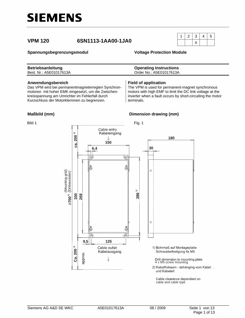
Anschlussschema Wiring diagram Bild 2a Fig. 2a
cable lengthKabellängemax. 50m
VPM 120
SIMODRIVE 611
Kl 9: enabling voltage / Freigabespannung
Kl 663: pulse enabling / Impulsfreigabe
U3 V3
PEU4
MPE
X3
cl
l llm
xm
Cable length Kabellänge max. 50m
Cab
le le
ngth
Kab
ellä
nge
max
. 1.5
m
Klemme 663: ImpulsfreigabeTerminal 663: pulse enable
Klemme 9: FreigabespannungTerminal 9: enabling voltage
Motor
Siemens AG A&D SE WKC A5E01017613A 08 / 2009 Seite 3 von 13 Page 3 of 13
Bild 2b Fig. 2b
Siemens AG A&D SE WKC A5E01017613A 08 / 2009 Seite 4 von 13 Page 4 of 13
Definitionen und Warnungen
QUALIFIZIERTES PERSONAL
Definitions and warnings
QUALIFIED PERSONNEL
im Sinne der Betriebsanleitung bzw. der Warnhinweise auf dem Produkt selbst sind Personen, die mit Aufstellung. Montage, Inbetriebsetzung und Betrieb des Produktes vertraut sind und über die ihrer Tätigkeit entsprechenden Qualifikation verfügen wie z. B.:
1. Ausbildung oder Unterweisung bzw. Berechtigung, Stromkreise und Geräte gemäß den Standards der Sicherheitstechnik ein- und auszuschalten, zu erden und zu kennzeichnen.
2. Ausbildung oder Unterweisung gemäß den Standards der Sicherheitstechnik in Pflege und Gebrauch angemessener Sicherheitsausrüstung.
3. Schulung in Erster Hilfe
! GEFAHR
bedeutet, dass Tod, schwere Körperverletzung oder erheblicher Sachschaden eintreten werden, wenn die entsprechenden Vorsichtsmaßnahmen nicht getroffen werden.
! WARNUNG
bedeutet, dass Tod oder schwere Körperverletzungen eintreten können, wenn die entsprechenden Vorsichtsmaßnahmen nicht getroffen werden.
! VORSICHT
mit Warndreieck bedeutet, dass eine leichte Körperverletzung eintreten kann, wenn die entsprechenden Vorsichtsmaßnahmen nicht getroffen werden.
VORSICHT
ohne Warndreieck bedeutet, dass ein Sachschaden eintreten kann, wenn die entsprechenden Vorsichtsmaßnahmen nicht getroffen werden.
ACHTUNG
bedeutet, dass ein unerwünschtes Ergebnis oder Zustand eintreten kann, wenn der entsprechende Hinweis nicht beachtet wird.
HINWEIS
im Sinne dieser Betriebsanleitung ist eine wichtige Information über das Produkt oder den jeweiligen Teil der Betriebsanleitung, auf die besonders aufmerksam gemacht werden soll.
as referred to in the safety guidelines of these Operating Instructions and on the product itself are persons who are conversant with the setting up, installation, commissioning and operation of the product and who possess qualifications appropriate to their field of work. For example, they should be:
1. Trained, instructed or authorized to switch, to ground and tag circuits and systems in accordance with the relevant standards for safety equipment.
2. Trained or instructed in the maintenance and use of appropriate safety devices in accordance with the relevant standards for safety equipment.
3. Trained in rendering first aid. ! DANGER
indicates an imminently hazardous situation which, if not avoided, will result in death or serious injury. ! WARNING
indicates a potentially hazardous situation which, if not avoided, could result in death or serious injury. ! CAUTION
used with the safety alert symbol indicates a potentially hazardous situation which, if not avoided, may result in minor or moderate injury.
CAUTION used without safety alert symbol indicates a potentially hazardous situation which, if not avoided, may result in property damage.
NOTICE used without the safety alert symbol indicates a potential situation which, if not avoided, may result in an undesirable result or state. NOTE as referred to in these Operating Instructions is important information about the product or the relevant part of the Operating Instructions to which special attention is drawn.
Siemens AG A&D SE WKC A5E01017613A 08 / 2009 Seite 5 von 13 Page 5 of 13
HINWEIS Diese Betriebsanleitung enthält aus Gründen der Übersichtlichkeit nicht sämtliche Detailinformationen zu allen Typen des Produkts und kann auch nicht jeden denkbaren Fall der Aufstellung, des Betriebes oder der Instandhaltung berücksichtigen. Sollten Sie weitere Informationen wünschen, oder sollten besondere Probleme auftreten, die in der Betriebsanleitung nicht ausführlich genug behandelt werden, können sie die erforderliche Auskunft über die örtliche Siemens- Niederlassung anfordern. Außerdem weisen wir darauf hin, dass der Inhalt dieser Betriebsanleitung nicht Teil einer früheren oder bestehenden Vereinbarung, Zusage oder eines Rechtsverhältnisses ist oder dieses abändern soll. Sämtliche Verpflichtungen von Siemens ergeben sich aus dem jeweiligen Kaufvertrag, der auch die vollständige und allein gültige Gewährleistungsregelung enthält. Diese vertraglichen Gewährleistungsbestimmungen werden durch die Ausführungen dieser Betriebsanleitung weder erweitert noch beschränkt.
NOTE In order to maintain clarity, these Operating Instructions do not contain all details on all types of the product described herein. It cannot therefore consider all possible cases of installation, operation and repair. If you require additional information or should any special problems arise, please request further information from your local Siemens branch office. Furthermore, we ask you to be aware of the fact that the contents of these Operating Instructions are not part of any earlier or existing agreement, commitment or legal undertaking, nor are they intended as an amendment thereto. All responsibilities on the part of Siemens shall result only from the respective purchase contract, which also contains the complete and solely binding warranty regulations. The warranty provisions laid down by the contract shall neither be extended, nor restricted by these Operating Instructions.
VORSICHT Elektrostatisch gefährdete Bauelemente (EGB)
CAUTION Electrostatic sensitive devices (ESD)
Das VPM enthält elektrostatisch gefährdete Bauelemente. Diese Bauelemente können durch unsachgemäße Behandlung sehr leicht zerstört werden.
e Die entsprechenden Hinweise im Abschnitt „Installation“ sind zu beachten.
The VPM contains electrostatic sensitive devices. These devices can be destroyed if handled inappropriate. Please observe the notes in the Section “Installation”.
Siemens AG A&D SE WKC A5E01017613A 08 / 2009 Seite 6 von 13 Page 6 of 13
Technische Hinweise: ! WARNUNG
• Das VPM ist konzeptgeprüft freigegeben mit den
Systemen: SIMODRIVE 611 digital, SIMODRIVE 611 universal, geschirmter MOTION- CONNECT 800- Motorleitung und permanentmagnet- erregten 1FE1- Synchronmotoren SINAMICS Booksize, geschirmter MOTION- CONNECT 800- Motorleitung und permanentmagneterregten 1FE1/2SP1- Synchronmotoren Soll das VPM mit anderen als den oben genannten Komponenten eingesetzt werden, muss der Anwender eine Risikoanalyse durchführen. Die elektrischen Eigenschaften der alternativ eingesetzten Komponenten müssen denen der spezifizierten SIEMENS- Komponenten entsprechen. • Die Kennwerte von VPM und Motor dürfen unter allen Betriebszuständen nicht überschritten werden (siehe „Technische Daten).
• Es dürfen nur kurzschlussfeste Motoren eingesetzt werden.
! GEFAHR • Beim Betrieb elektrischer Geräte stehen
zwangsläufig bestimmte Teile dieser Geräte unter gefährlicher Spannung.
Bei Nichtbeachtung der Warnhinweise können deshalb schwere Körperverletzungen oder Sach- schäden auftreten. • Nur entsprechend qualifiziertes Personal darf an
diesem Gerät arbeiten. Dieses Personal muss gründlich mit allen Warnungen und Instandhaltungsmaßnahmen gemäß dieser Betriebsanleitung vertraut sein. • Der einwandfreie und sichere Betrieb dieses Gerätes
setzt sachgemäßen Transport, fach-gerechte Lagerung, Aufstellung und Montage sowie sorgfältige Bedienung und Instandhaltung voraus.
• Die auf dem Gerät angebrachten Warnhinweise sind
zu beachten.
Technical notes: ! WARNING
• The VPM has been released with verified concept
for the following systems: SIMODRIVE 611 digital, SIMODRIVE 611universal, shielded MOTION- CONNECT 800 motor cable and 1FE1- permanent-magnet synchronous motors SINAMICS Booksize, shielded MOTION- CONNECT 800 motor cable and 1FE1/2SP1- permanent-magnet synchronous motors If the VPM is to be used with components other than those mentioned above, the user must carry out a risk analysis. The electric properties of the alternatively used components must correspond to those of the specified SIEMENS components.
• Do not exceed the characteristic values of the VPM and motor under all operating conditions (see "Technical data").
• Only short- circuit proof motors may be used. ! DANGER
• During the operation of any electrical devices, it is
inevitable that certain parts of these devices are under hazardous voltage.
Failure to comply with the warning notices can therefore result in severe personal injury or material demage.
• The device may only be operated by appropriately qualified personnel. This personnel must thoroughly be conversant with all warning notices and maintenance measures as described in these Operating Instructions.
• The problem-free and safe operation of this device
assumes correct transportation, storage, installation and mounting, as well as proper operation and maintenance.
• Observe the warning notices on the device.
Siemens AG A&D SE WKC A5E01017613A 08 / 2009 Seite 7 von 13 Page 7 of 13
• Das VPM ist ein Einbaugerät, ausgelegt für den Einsatz im Industriebereich. Für die Installation des Gerätes sind die einschlägigen DIN / VDE- Bestim-mungen oder länderspezifischen Vorschriften zu beachten.
• Das Gerät ist eine Sicherheitsschalteinrichtung und
nur bestimmungsgemäß einzusetzen (siehe „Anwendungsbereich“, S.1).
Andere Anwendungen, z. B. betriebsmäßiger
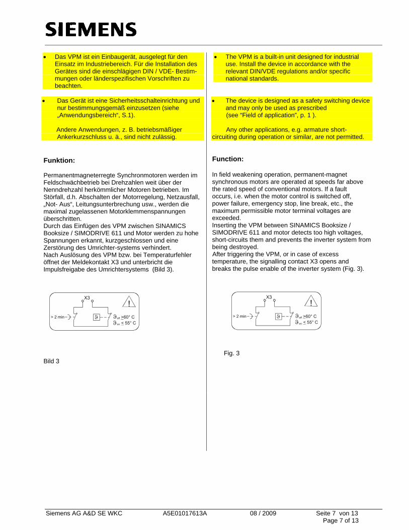
Ankerkurzschluss u. ä., sind nicht zulässig. Funktion: Permanentmagneterregte Synchronmotoren werden im Feldschwächbetrieb bei Drehzahlen weit über der Nenndrehzahl herkömmlicher Motoren betrieben. Im Störfall, d.h. Abschalten der Motorregelung, Netzausfall, „Not- Aus“, Leitungsunterbrechung usw., werden die maximal zugelassenen Motorklemmenspannungen überschritten. Durch das Einfügen des VPM zwischen SINAMICS Booksize / SIMODRIVE 611 und Motor werden zu hohe Spannungen erkannt, kurzgeschlossen und eine Zerstörung des Umrichter-systems verhindert. Nach Auslösung des VPM bzw. bei Temperaturfehler öffnet der Meldekontakt X3 und unterbricht die Impulsfreigabe des Umrichtersystems (Bild 3).
Bild 3
• The VPM is a built-in unit designed for industrial use. Install the device in accordance with the relevant DIN/VDE regulations and/or specific national standards.
• The device is designed as a safety switching device
and may only be used as prescribed (see “Field of application”, p. 1 ). Any other applications, e.g. armature short-circuiting during operation or similar, are not permitted.
Function: In field weakening operation, permanent-magnet synchronous motors are operated at speeds far above the rated speed of conventional motors. If a fault occurs, i.e. when the motor control is switched off, power failure, emergency stop, line break, etc., the maximum permissible motor terminal voltages are exceeded. Inserting the VPM between SINAMICS Booksize / SIMODRIVE 611 and motor detects too high voltages, short-circuits them and prevents the inverter system from being destroyed.
After triggering the VPM, or in case of excess temperature, the signalling contact X3 opens and breaks the pulse enable of the inverter system (Fig. 3).
Fig. 3
Siemens AG A&D SE WKC A5E01017613A 08 / 2009 Seite 8 von 13 Page 8 of 13
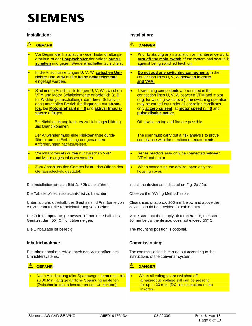
Installation: ! GEFAHR
• Vor Beginn der Installations- oder Instandhaltungs-
arbeiten ist der Hauptschalter der Anlage auszu-schalten und gegen Wiedereinschalten zu sichern.
• In die Anschlussleitungen U, V, W zwischen Um-
richter und VPM dürfen keine Schaltelemente eingefügt werden.
• Sind in den Anschlussleitungen U, V, W zwischen
VPM und Motor Schaltelemente erforderlich (z. B. für Wicklungsumschaltung), darf deren Schaltvor-gang unter allen Betriebsbedingungen nur strom-los, bei Motordrehzahl n = 0 und aktiver Impuls-sperre erfolgen.
Bei Nichtbeachtung kann es zu Lichtbogenbildung und Brand kommen. Der Anwender muss eine Risikoanalyse durch- führen, um die Einhaltung der genannten Anforderungen nachzuweisen. • Vorschaltdrosseln dürfen nur zwischen VPM und Motor angeschlossen werden. • Zum Anschluss des Gerätes ist nur das Öffnen des
Gehäusedeckels gestattet. Die Installation ist nach Bild 2a / 2b auszuführen. Die Tabelle „Anschlusstechnik“ ist zu beachten. Unterhalb und oberhalb des Gerätes sind Freiräume von ca. 200 mm für die Kabeleinführung vorzusehen. Die Zulufttemperatur, gemessen 10 mm unterhalb des Gerätes, darf 55° C nicht übersteigen. Die Einbaulage ist beliebig. Inbetriebnahme:
Die Inbetriebnahme erfolgt nach den Vorschriften des Umrichtersystems. ! GEFAHR • Nach Abschaltung aller Spannungen kann noch bis
zu 30 Min. lang gefährliche Spannung anstehen (Zwischenkreiskondensatoren des Umrichters).
Installation: ! DANGER
• Prior to starting any installation or maintenance work,
turn off the main switch of the system and secure it against being switched back on.
• Do not add any switching components in the connection lines U, V, W between inverter and VPM.
• If switching components are required in the connection lines U, V, W between VPM and motor (e.g. for winding switchover), the switching operation may be carried out under all operating conditions only at zero current, at motor speed n = 0 and pulse disable active. Otherwise arcing and fire are possible.
The user must carry out a risk analysis to prove compliance with the mentioned requirements.
• Series reactors may only be connected between VPM and motor.
• When connecting the device, open only the housing cover.
Install the device as indicated on Fig. 2a / 2b. Observe the "Wiring Method" table. Clearances of approx. 200 mm below and above the device should be provided for cable entry. Make sure that the supply air temperature, measured 10 mm below the device, does not exceed 55° C. The mounting position is optional. Commissioning: The commissioning is carried out according to the instructions of the converter system. ! DANGER
• When all voltages are switched off, a hazardous voltage still can be present for up to 30 min. (DC link capacitors of the inverter).
Siemens AG A&D SE WKC A5E01017613A 08 / 2009 Seite 9 von 13 Page 9 of 13
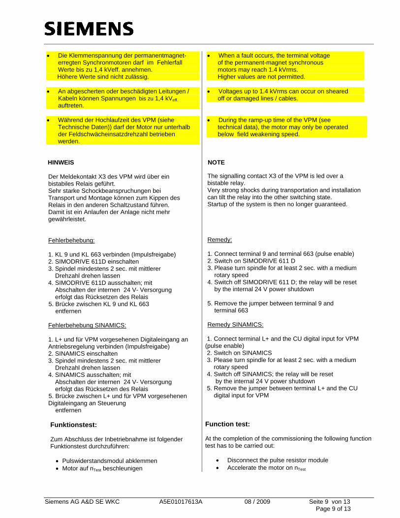
• Die Klemmenspannung der permanentmagnet-erregten Synchronmotoren darf im Fehlerfall Werte bis zu 1,4 kVeff. annehmen.
Höhere Werte sind nicht zulässig. • An abgescherten oder beschädigten Leitungen /
Kabeln können Spannungen bis zu 1,4 kVeff. auftreten.
• Während der Hochlaufzeit des VPM (siehe
Technische Daten)) darf der Motor nur unterhalb der Feldschwächeinsatzdrehzahl betrieben werden.
HINWEIS Der Meldekontakt X3 des VPM wird über ein bistabiles Relais geführt. Sehr starke Schockbeanspruchungen bei Transport und Montage können zum Kippen des Relais in den anderen Schaltzustand führen. Damit ist ein Anlaufen der Anlage nicht mehr gewährleistet. Fehlerbehebung: 1. KL 9 und KL 663 verbinden (Impulsfreigabe) 2. SIMODRIVE 611D einschalten 3. Spindel mindestens 2 sec. mit mittlerer Drehzahl drehen lassen 4. SIMODRIVE 611D ausschalten; mit Abschalten der internen 24 V- Versorgung erfolgt das Rücksetzen des Relais
5. Brücke zwischen KL 9 und KL 663 entfernen
Fehlerbehebung SINAMICS: 1. L+ und für VPM vorgesehenen Digitaleingang an Antriebsregelung verbinden (Impulsfreigabe) 2. SINAMICS einschalten 3. Spindel mindestens 2 sec. mit mittlerer Drehzahl drehen lassen 4. SINAMICS ausschalten; mit Abschalten der internen 24 V- Versorgung erfolgt das Rücksetzen des Relais
5. Brücke zwischen L+ und für VPM vorgesehenen Digitaleingang an Steuerung
entfernen
Funktionstest:
Zum Abschluss der Inbetriebnahme ist folgender Funktionstest durchzuführen:
• Pulswiderstandsmodul abklemmen • Motor auf nTest beschleunigen
• When a fault occurs, the terminal voltage of the permanent-magnet synchronous motors may reach 1.4 kVrms. Higher values are not permitted.
• Voltages up to 1.4 kVrms can occur on sheared off or damaged lines / cables. • During the ramp-up time of the VPM (see technical data), the motor may only be operated below field weakening speed.
NOTE The signalling contact X3 of the VPM is led over a bistable relay. Very strong shocks during transportation and installation can tilt the relay into the other switching state. Startup of the system is then no longer guaranteed.
Remedy: 1. Connect terminal 9 and terminal 663 (pulse enable) 2. Switch on SIMODRIVE 611 D 3. Please turn spindle for at least 2 sec. with a medium rotary speed 4. Switch off SIMODRIVE 611 D; the relay will be reset by the internal 24 V power shutdown 5. Remove the jumper between terminal 9 and terminal 663
Remedy SINAMICS:
1. Connect terminal L+ and the CU digital input for VPM (pulse enable) 2. Switch on SINAMICS 3. Please turn spindle for at least 2 sec. with a medium rotary speed 4. Switch off SINAMICS; the relay will be reset by the internal 24 V power shutdown 5. Remove the jumper between terminal L+ and the CU digital input for VPM Function test: At the completion of the commissioning the following function test has to be carried out:
• Disconnect the pulse resistor module • Accelerate the motor on nTest
Siemens AG A&D SE WKC A5E01017613A 08 / 2009 Seite 10 von 13 Page 10 of 13
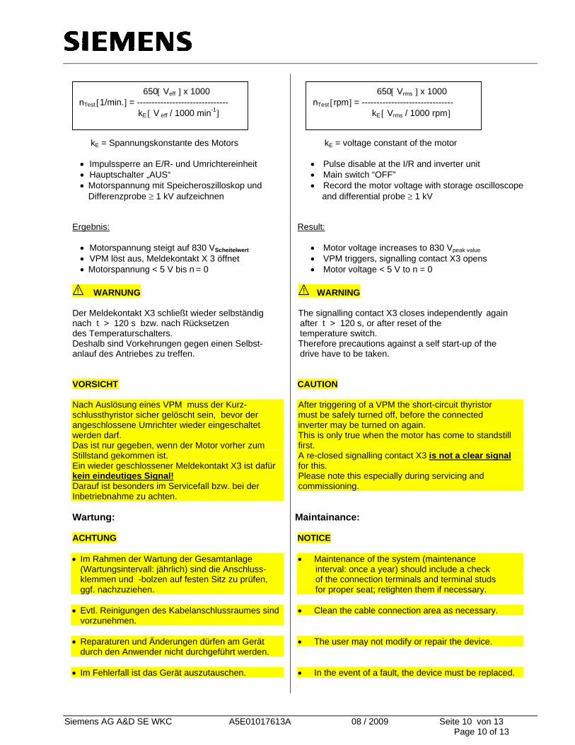
kE = Spannungskonstante des Motors
• Impulssperre an E/R- und Umrichtereinheit • Hauptschalter „AUS“ • Motorspannung mit Speicheroszilloskop und
Differenzprobe ≥ 1 kV aufzeichnen
Ergebnis:
• Motorspannung steigt auf 830 VScheitelwert • VPM löst aus, Meldekontakt X 3 öffnet • Motorspannung < 5 V bis n = 0
! WARNUNG
Der Meldekontakt X3 schließt wieder selbständig nach t > 120 s bzw. nach Rücksetzen des Temperaturschalters. Deshalb sind Vorkehrungen gegen einen Selbst- anlauf des Antriebes zu treffen. VORSICHT Nach Auslösung eines VPM muss der Kurz- schlussthyristor sicher gelöscht sein, bevor der angeschlossene Umrichter wieder eingeschaltet werden darf. Das ist nur gegeben, wenn der Motor vorher zum Stillstand gekommen ist. Ein wieder geschlossener Meldekontakt X3 ist dafür kein eindeutiges Signal! Darauf ist besonders im Servicefall bzw. bei der Inbetriebnahme zu achten.
Wartung:
ACHTUNG
• Im Rahmen der Wartung der Gesamtanlage (Wartungsintervall: jährlich) sind die Anschluss- klemmen und -bolzen auf festen Sitz zu prüfen, ggf. nachzuziehen.
• Evtl. Reinigungen des Kabelanschlussraumes sind
vorzunehmen. • Reparaturen und Änderungen dürfen am Gerät
durch den Anwender nicht durchgeführt werden. • Im Fehlerfall ist das Gerät auszutauschen.
kE = voltage constant of the motor
• Pulse disable at the I/R and inverter unit • Main switch “OFF” • Record the motor voltage with storage oscilloscope
and differential probe ≥ 1 kV Result:
• Motor voltage increases to 830 Vpeak value • VPM triggers, signalling contact X3 opens • Motor voltage < 5 V to n = 0
! WARNING
The signalling contact X3 closes independently again after t > 120 s, or after reset of the temperature switch. Therefore precautions against a self start-up of the drive have to be taken. CAUTION After triggering of a VPM the short-circuit thyristor must be safely turned off, before the connected inverter may be turned on again. This is only true when the motor has come to standstill first. A re-closed signalling contact X3 is not a clear signal for this. Please note this especially during servicing and commissioning.
Maintainance: NOTICE • Maintenance of the system (maintenance interval: once a year) should include a check of the connection terminals and terminal studs for proper seat; retighten them if necessary.
• Clean the cable connection area as necessary.
• The user may not modify or repair the device.
• In the event of a fault, the device must be replaced.
650[ Veff ] x 1000 nTest [1/min.] = ------------------------------- kE [ V eff / 1000 min-1]
650[ Vrms ] x 1000 nTest [rpm] = ------------------------------- kE [ Vrms / 1000 rpm]
Siemens AG A&D SE WKC A5E01017613A 08 / 2009 Seite 11 von 13 Page 11 of 13
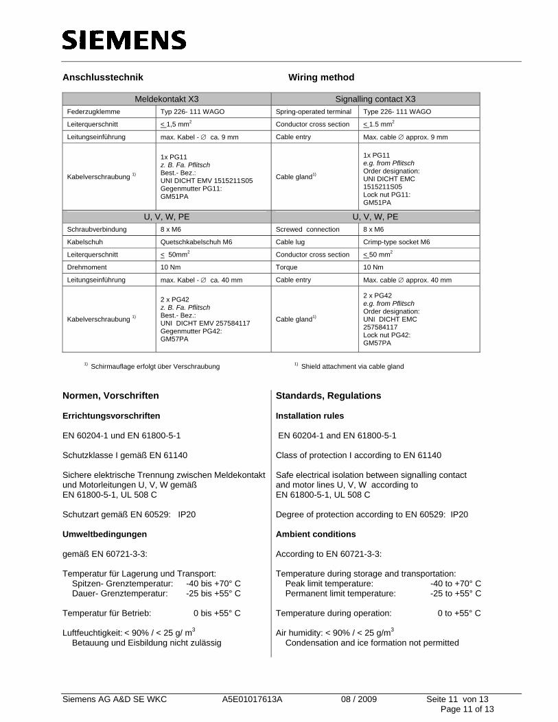
Anschlusstechnik Wiring method
Meldekontakt X3 Signalling contact X3 Federzugklemme Typ 226- 111 WAGO Spring-operated terminal Type 226- 111 WAGO
Leiterquerschnitt < 1,5 mm2 Conductor cross section < 1.5 mm2
Leitungseinführung max. Kabel - ∅ ca. 9 mm Cable entry Max. cable ∅ approx. 9 mm
Kabelverschraubung 1)
1x PG11 z. B. Fa. Pflitsch Best.- Bez.: UNI DICHT EMV 1515211S05 Gegenmutter PG11: GM51PA
Cable gland1)
1x PG11 e.g. from Pflitsch Order designation: UNI DICHT EMC 1515211S05 Lock nut PG11: GM51PA
U, V, W, PE U, V, W, PE Schraubverbindung 8 x M6 Screwed connection 8 x M6
Kabelschuh Quetschkabelschuh M6 Cable lug Crimp-type socket M6
Leiterquerschnitt < 50mm2 Conductor cross section < 50 mm2
Drehmoment 10 Nm Torque 10 Nm
Leitungseinführung max. Kabel - ∅ ca. 40 mm Cable entry Max. cable ∅ approx. 40 mm
Kabelverschraubung 1)
2 x PG42 z. B. Fa. Pflitsch Best.- Bez.: UNI DICHT EMV 257584117 Gegenmutter PG42: GM57PA
Cable gland1)
2 x PG42 e.g. from Pflitsch Order designation: UNI DICHT EMC 257584117 Lock nut PG42: GM57PA
1) Schirmauflage erfolgt über Verschraubung 1) Shield attachment via cable gland Normen, Vorschriften Errichtungsvorschriften EN 60204-1 und EN 61800-5-1 Schutzklasse I gemäß EN 61140 Sichere elektrische Trennung zwischen Meldekontakt und Motorleitungen U, V, W gemäß EN 61800-5-1, UL 508 C Schutzart gemäß EN 60529: IP20 Umweltbedingungen gemäß EN 60721-3-3: Temperatur für Lagerung und Transport: Spitzen- Grenztemperatur: -40 bis +70° C Dauer- Grenztemperatur: -25 bis +55° C Temperatur für Betrieb: 0 bis +55° C Luftfeuchtigkeit: < 90% / < 25 g/ m3 Betauung und Eisbildung nicht zulässig
Standards, Regulations Installation rules EN 60204-1 and EN 61800-5-1 Class of protection I according to EN 61140 Safe electrical isolation between signalling contact and motor lines U, V, W according to EN 61800-5-1, UL 508 C Degree of protection according to EN 60529: IP20 Ambient conditions According to EN 60721-3-3: Temperature during storage and transportation: Peak limit temperature: -40 to +70° C Permanent limit temperature: -25 to +55° C Temperature during operation: 0 to +55° C Air humidity: < 90% / < 25 g/m3 Condensation and ice formation not permitted
Siemens AG A&D SE WKC A5E01017613A 08 / 2009 Seite 12 von 13 Page 12 of 13
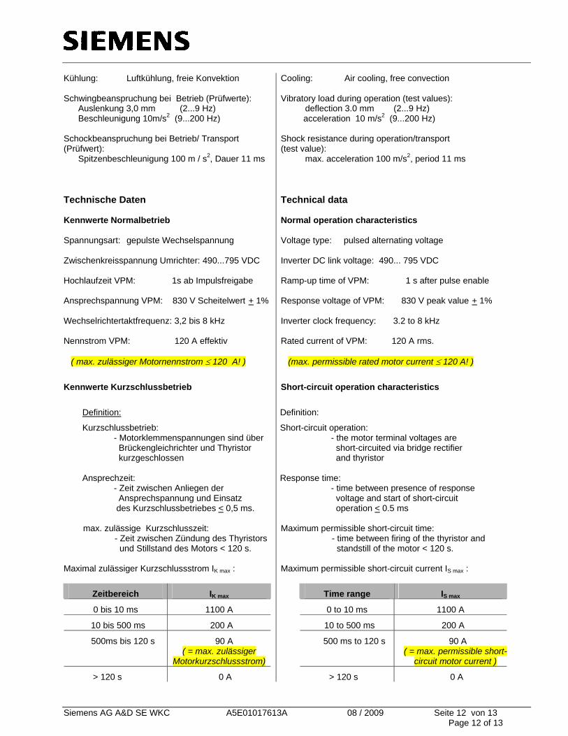
Kühlung: Luftkühlung, freie Konvektion Schwingbeanspruchung bei Betrieb (Prüfwerte): Auslenkung 3,0 mm (2...9 Hz) Beschleunigung 10m/s2 (9...200 Hz) Schockbeanspruchung bei Betrieb/ Transport (Prüfwert): Spitzenbeschleunigung 100 m / s2, Dauer 11 ms
Cooling: Air cooling, free convection Vibratory load during operation (test values): deflection 3.0 mm (2...9 Hz) acceleration 10 m/s2 (9...200 Hz)
Shock resistance during operation/transport (test value): max. acceleration 100 m/s2, period 11 ms
Technische Daten Kennwerte Normalbetrieb Spannungsart: gepulste Wechselspannung Zwischenkreisspannung Umrichter: 490...795 VDC Hochlaufzeit VPM: 1s ab Impulsfreigabe Ansprechspannung VPM: 830 V Scheitelwert + 1% Wechselrichtertaktfrequenz: 3,2 bis 8 kHz Nennstrom VPM: 120 A effektiv ( max. zulässiger Motornennstrom ≤ 120 A! )
Kennwerte Kurzschlussbetrieb
Definition:
Kurzschlussbetrieb: - Motorklemmenspannungen sind über Brückengleichrichter und Thyristor kurzgeschlossen Ansprechzeit: - Zeit zwischen Anliegen der Ansprechspannung und Einsatz des Kurzschlussbetriebes < 0,5 ms. max. zulässige Kurzschlusszeit: - Zeit zwischen Zündung des Thyristors und Stillstand des Motors < 120 s. Maximal zulässiger Kurzschlussstrom IK max :
Zeitbereich IK max
0 bis 10 ms 1100 A
10 bis 500 ms 200 A
500ms bis 120 s 90 A ( = max. zulässiger
Motorkurzschlussstrom)
> 120 s 0 A
Technical data Normal operation characteristics Voltage type: pulsed alternating voltage Inverter DC link voltage: 490... 795 VDC Ramp-up time of VPM: 1 s after pulse enable Response voltage of VPM: 830 V peak value + 1% Inverter clock frequency: 3.2 to 8 kHz Rated current of VPM: 120 A rms. (max. permissible rated motor current ≤ 120 A! )
Short-circuit operation characteristics
Definition:
Short-circuit operation: - the motor terminal voltages are short-circuited via bridge rectifier and thyristor Response time: - time between presence of response voltage and start of short-circuit operation < 0.5 ms Maximum permissible short-circuit time: - time between firing of the thyristor and standstill of the motor < 120 s. Maximum permissible short-circuit current IS max :
Time range IS max
0 to 10 ms 1100 A
10 to 500 ms 200 A
500 ms to 120 s 90 A ( = max. permissible short-
circuit motor current )
> 120 s 0 A
Siemens AG A&D SE WKC A5E01017613A 08 / 2009 Seite 13 von 13 Page 13 of 13
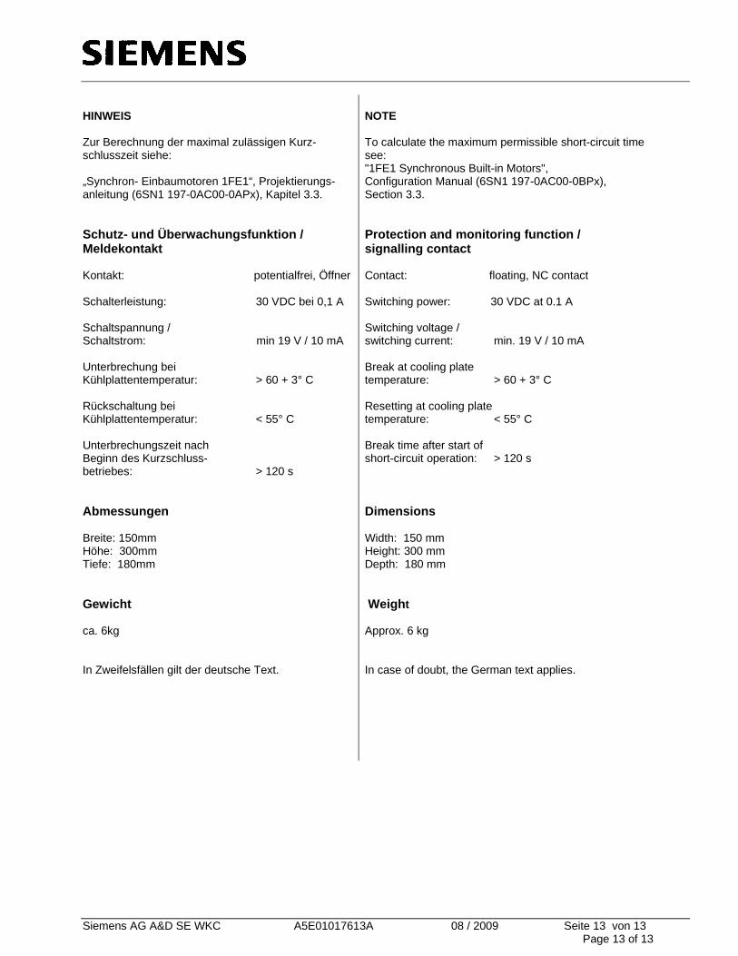
HINWEIS Zur Berechnung der maximal zulässigen Kurz-schlusszeit siehe: „Synchron- Einbaumotoren 1FE1“, Projektierungs-anleitung (6SN1 197-0AC00-0APx), Kapitel 3.3. Schutz- und Überwachungsfunktion / Meldekontakt Kontakt: potentialfrei, Öffner Schalterleistung: 30 VDC bei 0,1 A Schaltspannung / Schaltstrom: min 19 V / 10 mA Unterbrechung bei Kühlplattentemperatur: > 60 + 3° C Rückschaltung bei Kühlplattentemperatur: < 55° C Unterbrechungszeit nach Beginn des Kurzschluss- betriebes: > 120 s Abmessungen Breite: 150mm Höhe: 300mm Tiefe: 180mm Gewicht ca. 6kg In Zweifelsfällen gilt der deutsche Text.
NOTE To calculate the maximum permissible short-circuit time see: "1FE1 Synchronous Built-in Motors", Configuration Manual (6SN1 197-0AC00-0BPx), Section 3.3. Protection and monitoring function / signalling contact Contact: floating, NC contact Switching power: 30 VDC at 0.1 A Switching voltage / switching current: min. 19 V / 10 mA Break at cooling plate temperature: > 60 + 3° C Resetting at cooling plate temperature: < 55° C Break time after start of short-circuit operation: > 120 s Dimensions Width: 150 mm Height: 300 mm Depth: 180 mm Weight Approx. 6 kg In case of doubt, the German text applies.


![VPM Katalog 2008 fr[1]Photos VPM: Martin Raget, O. 3abinet, Rubinstein, p. Blanc NF / perousse, Morandi, H, Berthiau, OenSHuot, Jeanneau, Fonta ne.pajot 4/5 16-17 24-25 26-38 BES Notre](https://img.pdfslide.org/doc/110x75/5f31cb2c0b2fcf2aba2f73f6/vpm-katalog-2008-fr1-photos-vpm-martin-raget-o-3abinet-rubinstein-p-blanc.jpg)