Embed Size (px)
Citation preview
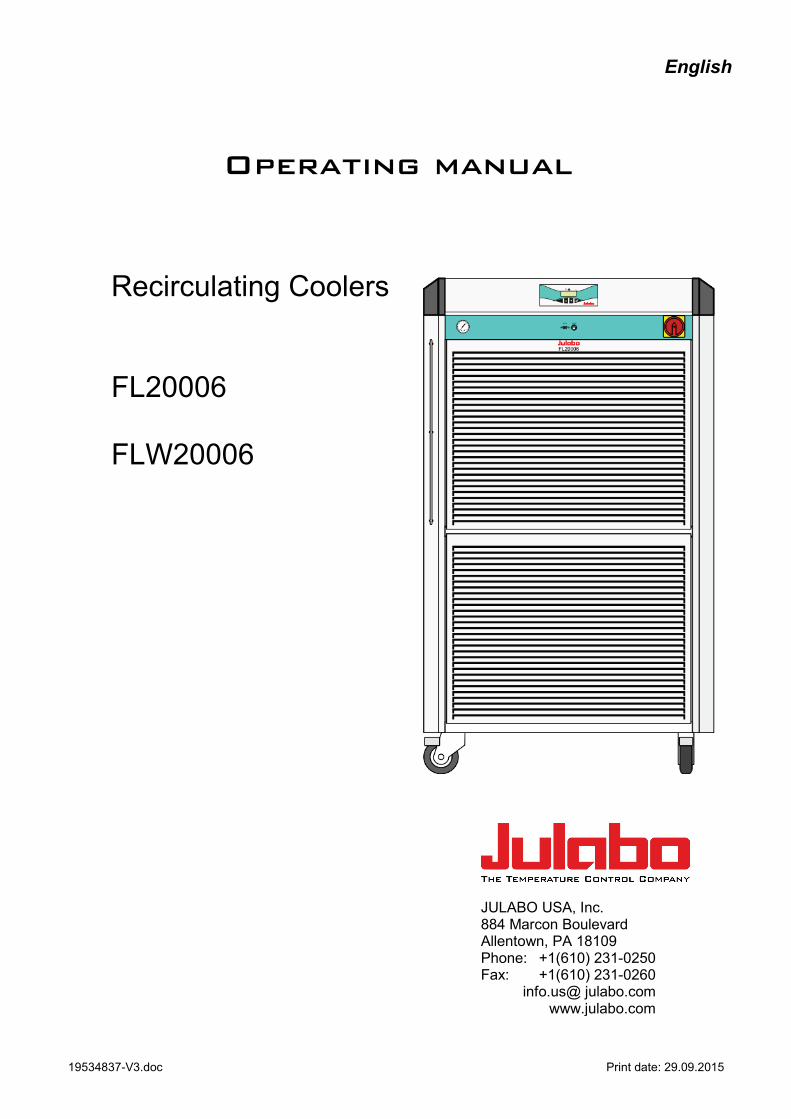
English
Operating manual
Recirculating Coolers FL20006 FLW20006
JULABO USA, Inc. 884 Marcon Boulevard Allentown, PA 18109 Phone: +1(610) 231-0250 Fax: +1(610) 231-0260 info.us@ julabo.com www.julabo.com
19534837-V3.doc Print date: 29.09.2015
Congratulations! You have made an excellent choice. JULABO thanks you for the trust you have placed in us. This operating manual has been designed to help you gain an understanding of the operation and possible applications of our circulators. For optimal utilization of all functions, we recommend that you thoroughly study this manual prior to beginning operation. The JULABO Quality Management System
Temperature control devices for research and industry are developed, produced, and distributed according to the requirements of ISO 9001 and ISO 14001. Certificate Registration No. 01 100044846
Unpacking and inspecting
Unpack the recirculating cooler and accessories and check for damages incurred during transit. These should be reported to the responsible carrier, railway, or postal authority, and a request for a damage report should be made. These instructions must be followed fully for us to guarantee our full support of your claim for protecting against loss from concealed damage. The form required for filing such a claim will be provided by the carrier.
1.953.4837-V3 10/15 Printed in Germany Changes without prior notification reserved
Important: keep operating manual for future use
2
TABLE OF CONTENTS
1. Intended use ............................................................................................................................... 5
1.1. Description ...................................................................................................................... 5
2. Operator responsibility – Safety instructions ............................................................................... 5
2.1. Installation Log for FL20006 ............................................................................................ 7
2.2. Disposal .......................................................................................................................... 7
2.3. Technical specifications .................................................................................................. 8
2.4. Cooling water connection .............................................................................................. 10
3. Safety notes for the user ........................................................................................................... 11
3.1. Explanation of safety notes ........................................................................................... 11
3.2. Explanation of other notes ............................................................................................. 11
3.3. Safety instructions ......................................................................................................... 11
4. Installation ................................................................................................................................ 13
4.1. Tubing ........................................................................................................................... 15
5. Operating controls and functional elements .............................................................................. 16
6. Operating procedures ............................................................................................................... 18
6.1. Bath fluids ..................................................................................................................... 18
6.2. Power connection .......................................................................................................... 18
6.3. Filling ............................................................................................................................ 19
6.4. Switching on / Start - Stop ............................................................................................. 19
6.5. Setting the feed pressure .............................................................................................. 20
6.6. Setting the temperatures ............................................................................................... 20
6.7. AUTOSTART ON / OFF ................................................................................................ 21
6.8. Remote control: activate – deactivate ............................................................................ 21
7. Safety installations .................................................................................................................... 22
7.1. Excess temperature protection ...................................................................................... 22
7.2. Low level protection ...................................................................................................... 22
8. Troubleshooting guide / Error messages .................................................................................. 22
9. Electrical connections ............................................................................................................... 24
10. Remote control ................................................................................................................ 25
10.1. Setup for remote control ................................................................................................ 25
10.2. Communication with a PC or a superordinated data system.......................................... 25
10.3. List of commands .......................................................................................................... 26
10.4. Status messages ........................................................................................................... 26
10.5. Error messages ............................................................................................................. 27
11. Cleaning / repairing the unit ............................................................................................. 28
11.1. JULABO Service – Online remote diagnosis ................................................................. 30
11.2. Draining ........................................................................................................................ 31
12. WARRANTY PROVISIONS ............................................................................................. 32
13. Example Installation Log ................................................................................................. 34
3

4
1. Intended use JULABO recirculating coolers have been designed for temperature application to specific fluids. The pump connections can be used for cooling applications in an external circuit at a constant temperature.
JULABO water baths are not suitable for direct temperature control of foods, semi-luxury foods and tobacco, or pharmaceutical and medical products. Direct temperature control means unprotected contact of the object with the bath medium (bath fluid).
1.1. Description
PID1
RS232
The recirculating coolers are operated via the splash-proof keypad. The implemented microprocessor technology allows to set and to store the setpoint that can be indicated on the LED temperature display.
The PID temperature regulation is used to withdraw heat from the bath fluid by means of the cooling machine and to automatically regulate the required need.
Electrical connections: 1. The serial interface RS232 allows modern process technology without additional interface. 2. Alarm output for external alarm message.
Manually adjustable by-pass (handwheel) to reduce the pump capacity (e. g. for glass equipment).
2. Operator responsibility – Safety instructions The products of JULABO ensure safe operation when installed, operated, and maintained according to common safety regulations. This section explains the potential dangers that may arise when operating the circulator and also specifies the most important safety precautions to preclude these dangers as far as possible.
The operator is responsible for the qualification of the personnel operating the units.
The personnel operating the units should be regularly instructed about the dangers involved with their job activities as well as measures to avert these dangers.
Make sure all persons tasked with operating, installing, and maintaining the unit have read and understand the safety information and operating instructions.
When using hazardous materials or materials that could become hazardous, the unit may be operated only by persons who are absolutely familiar with these materials and the unit. These persons must be fully aware of possible risks.
If you have any questions concerning the operation of your unit or the information in this manual, please contact us!
Contact JULABO USA, Inc. 884 Marcon Boulevard Allentown, PA 18109
Phone: +1(610) 231-0250 Fax: +1(610) 231-0260 info.us@ julabo.com www.julabo.com
5
Safety recommendations for the operator You received a product developed for industrial use. Nevertheless, avoid strikes to the housing,
vibrations, damages to the keypad foil (keys, display) or contamination. Make sure the product is regularly checked for proper condition. Regularly check (at least every
2 years) the proper condition of the mandatory, warning, prohibition and safety labels. Take care that the mains supply features a low impedance to avoid any negative affects on the
instrument being operated in the same mains. This unit is designed for operation in a controlled electromagnetic environment. This means that
transmitting devices (e.g. cellular phones) should not be used in the immediate vicinity. Magnetic radiation may influence other units with components susceptible to magnetic fields (e.g. a monitor). We recommend to keep a minimum distance of 1 m.
Permissible ambient temperature: max. 40 °C, min. 5 °C. Permissible relative air humidity: 50 % (40 °C). Do not store in an aggressive atmosphere. Protect from contaminations. Do not expose to sunlight. Appropriate Operation Only qualified personnel is authorized to perform configuration, installation, maintenance and repairs of the water bath. Routine operation can also be carried out by untrained personnel who should however be instructed by trained personnel. Use For the use according to the intended purpose, special material requirements have to be respected (bath fluids). Only use non-acid and non corroding materials. Observe all warnings for the used materials (bath fluids) and the respective instructions (safety data sheets). Only use the unit in well ventilated areas. (see page 13). The recirculating coolers are not for use in explosive atmosphere When using hazardous materials or materials that could become hazardous, the operator must affix the enclosed safety labels (1 + 2) to the front of the unit so they are highly visible:
If this unit is intended for use within the United States of America, all 3 warning labels (1+2b+3) must be affixed to the housing of the unit prior to use. Directions for the positioning of the individual warning labels are enclosed with the warning labels included in the delivery. Warning labels must be easily visible to users.
1
Danger area. Attention! Observe instructions. (operating manual, safety data sheet)
2 or
Carefully read the user information prior to beginning operation. Scope: EU
2
Carefully read the user information prior to beginning operation. Scope: USA, NAFTA
3
Warning label Proposition 65
6
Observe the instructions in the manuals for instruments of a different make that you connect to the circulator, particularly the corresponding safety instructions. Also observe the pin assignment of plugs and technical specifications of the products.
2.1. Installation Log for FL20006
EN 378-4:2008-06
Documentation
The operator is obliged to keep an installation log for the refrigeration unit if the filling volume of the refrigerant exceeds 3 kg! The installation log must be kept with the unit. If the information and data is recorded on a computer, the current status must be printed out (hard copy) and kept with the unit. It must be assured that the log is available to an expert in case of repairs and repeated inspections. The installation log must include the following information: See example on page 34
2.2. Disposal This unit contains the refrigerant R404A, which at this time is not considered harmful to the ozone layer. However, over the long operating period of the unit, disposal rules may change. Therefore, only qualified personnel should handle the disposal.
Valid in EU countries: Directive 2002/96/EC of the European Parliament and of the Council of 27 January 2003 on waste electrical and electronic equipment (WEEE). This directive requires electrical and electronic equipment marked with a crossedout trash can to be disposed of separately in an environmentally friendly manner. Contact an authorized waste management company in your country. Disposal with household waste (unsorted waste) or similar collections of municipal waste is not permitted!
7
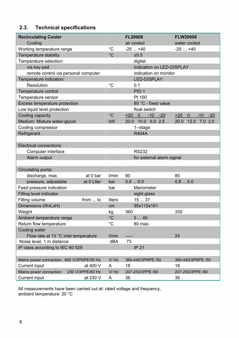
2.3. Technical specifications
Recirculating Cooler Cooling
FL20006 FLW20006 air cooled water cooled
Working temperature range °C -25 ... +40 -25 … +40 Temperature stability °C ±0.5 Temperature selection: digital via key pad indication on LED-DISPLAY remote control via personal computer indication on monitor Temperature indication: LED-DISPLAY Resolution °C 0.1 Temperature control PID 1 Temperature sensor Pt 100 Excess temperature protection 85 °C - fixed value Low liquid level protection float switch Cooling capacity Medium: Mixture water-glycol
°C kW
+20 0 -10 -20 +20 0 -10 -20 20.0 10.0 6.0 2.5 20.0 12.0 7.0 3.0
Cooling compressor 1--stage Refrigerant R404A Electrical connections: Computer interface RS232 Alarm output for external alarm signal Circulating pump: discharge, max. at 0 bar l/min 80 80 pressure, adjustable at 0 Liter bar 0.8 ... 6.0 0.8 ... 6.0 Feed pressure indication bar Manometer Filling level indicator sight glass Filling volume from ... to liters 15 ... 37 Dimensions (WxLxH) cm 95x115x161 Weight kg 360 330 Ambient temperature range °C 5 ... 40 Return flow temperature °C 80 max. Cooling water Flow rate at 15 °C inlet temperature
l/min
----- 24
Noise level, 1 m distance dBA 73 IP class according to IEC 60 529 IP 21 Mains power connection 400 V/3PNPE/50 Hz V/ Hz 360-440/3PNPE /50 360-440/3PNPE /50 Current input at 400 V A 18 18 Mains power connection 230 V/3PPE/60 Hz V/ Hz 207-253/3PPE /60 207-253/3PPE /60 Current input at 230 V A 36 36 All measurements have been carried out at: rated voltage and frequency, ambient temperature: 20 °C
8
Warning functions and safety installations Excess temperature protection 85 °C - fixed value Low liquid level protection float switch Alarm message optical + audible (permanent) Excess temperature - Warning function 75 °C Overload protection for compressor and pump motor Classification according to DIN 12876-1 class I Environmental conditions according to IEC 61 010-1: Use only indoor. Altitude up to 2000 m - normal zero. Ambient temperature: +5 ... +40 °C Air humidity: Max. rel. humidity 80 % for temperatures up to +31 °C, linear decrease down to 50 % relative humidity at a temperature of +40 °C Max. mains fluctuations of ±10 % are permissible. The unit corresponds to Class I Overvoltage category II Pollution degree 2
Caution: The unit is not for use in explosive environment.
Standards for interference resistance according to EN 61326-1 This unit is an ISM device classified in Group 1 (using high frequency for internal purposes) Class A (industrial and commercial range).
9
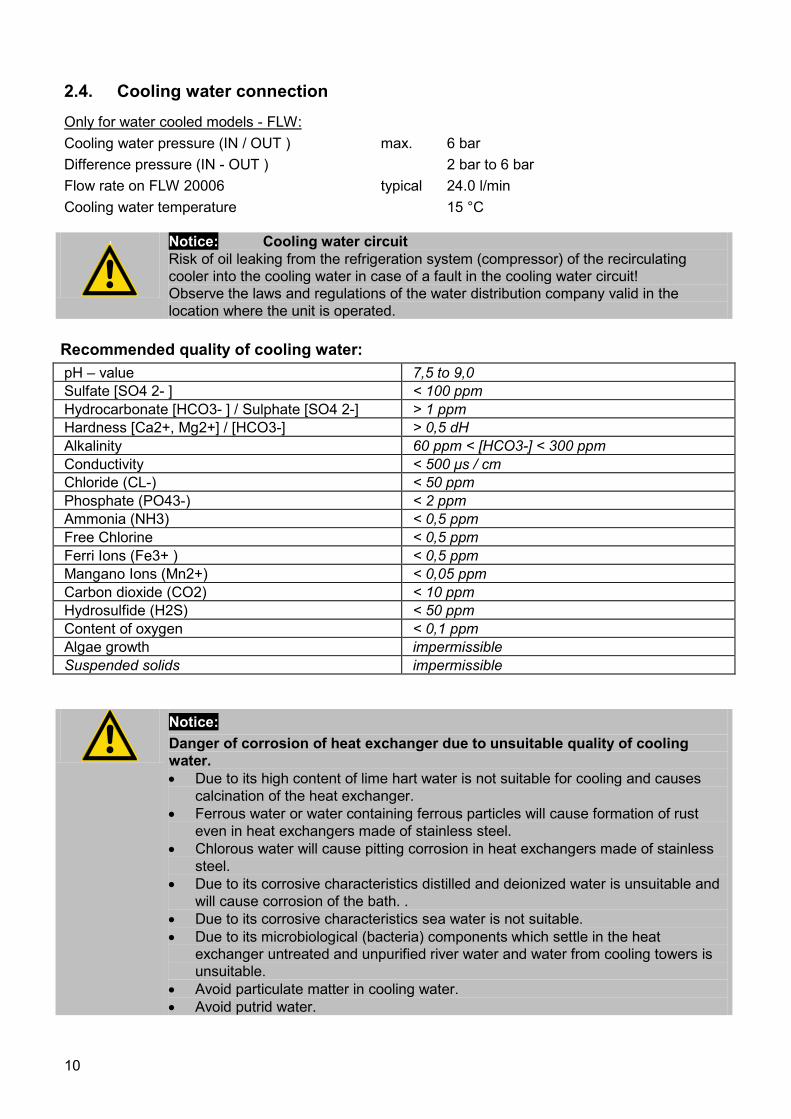
2.4. Cooling water connection Only for water cooled models - FLW: Cooling water pressure (IN / OUT ) max. 6 bar Difference pressure (IN - OUT ) 2 bar to 6 bar Flow rate on FLW 20006 typical 24.0 l/min Cooling water temperature 15 °C
Notice: Cooling water circuit Risk of oil leaking from the refrigeration system (compressor) of the recirculating cooler into the cooling water in case of a fault in the cooling water circuit! Observe the laws and regulations of the water distribution company valid in the location where the unit is operated.
Recommended quality of cooling water: pH – value 7,5 to 9,0 Sulfate [SO4 2- ] < 100 ppm Hydrocarbonate [HCO3- ] / Sulphate [SO4 2-] > 1 ppm Hardness [Ca2+, Mg2+] / [HCO3-] > 0,5 dH Alkalinity 60 ppm < [HCO3-] < 300 ppm Conductivity < 500 μs / cm Chloride (CL-) < 50 ppm Phosphate (PO43-) < 2 ppm Ammonia (NH3) < 0,5 ppm Free Chlorine < 0,5 ppm Ferri Ions (Fe3+ ) < 0,5 ppm Mangano Ions (Mn2+) < 0,05 ppm Carbon dioxide (CO2) < 10 ppm Hydrosulfide (H2S) < 50 ppm Content of oxygen < 0,1 ppm Algae growth impermissible Suspended solids impermissible
Notice: Danger of corrosion of heat exchanger due to unsuitable quality of cooling water. • Due to its high content of lime hart water is not suitable for cooling and causes
calcination of the heat exchanger. • Ferrous water or water containing ferrous particles will cause formation of rust
even in heat exchangers made of stainless steel. • Chlorous water will cause pitting corrosion in heat exchangers made of stainless
steel. • Due to its corrosive characteristics distilled and deionized water is unsuitable and
will cause corrosion of the bath. . • Due to its corrosive characteristics sea water is not suitable. • Due to its microbiological (bacteria) components which settle in the heat
exchanger untreated and unpurified river water and water from cooling towers is unsuitable.
• Avoid particulate matter in cooling water. • Avoid putrid water.
10
3. Safety notes for the user
3.1. Explanation of safety notes
In addition to the safety warnings listed above, warnings are posted throughout the manual. These warnings are designated by an exclamation mark inside an equilateral triangle. “Warning of a dangerous situation (Attention! Please follow the documentation).” The danger is classified using a signal word. Read and follow these important instructions.
Warning: Describes a possibly highly dangerous situation. If these instructions are not followed, serious injury and danger to life could result.
Caution: Describes a possibly dangerous situation. If this is not avoided, slight or minor injuries could result. A warning of possible property damage may also be contained in the text.
Notice: Describes a possibly harmful situation. If this is not avoided, the product or anything in its surroundings can be damaged.
3.2. Explanation of other notes
Note! Draws attention to something special.
Important! Indicates usage tips and other useful information.
3.3. Safety instructions Follow the safety recommendations to prevent damage to persons or property. Further,
the valid safety instructions for working places must be followed.
• Only connect the unit to a power socket with earthing contact (PE – protective earth)!
• The power supply plug serves as a safe disconnecting device from the line and must always be easily accessible.
• Place the instrument on an even surface on a pad made of non-inflammable material.
• Do not stay in the area below the unit. • Make sure you read and understand all instructions and safety precautions listed in
this manual before installing or operating your unit. • Never operate the unit without bath fluid in the bath. • Do not drain the bath fluid while it is hot or cold!
Check the temperature of the bath fluid prior to draining (by switching the unit on for a short moment for example).
• Use suitable connecting tubing.
11
• Avoid sharp bends in the tubing, and maintain a sufficient distance from surrounding walls.
• Make sure that the tubing is securely attached. • Regularly check the tubing for material defects (e.g., for cracks). • Never operate damaged or leaking equipment. • Always turn off the unit and disconnect the mains cable from the power source
before performing any service or maintenance procedures, or before moving the unit.
• Always turn off the unit and disconnect the mains cable from the power source before cleaning the unit.
• Always empty the bath before moving the unit. • Transport the unit with care. • Sudden jolts or drops may cause damage in the interior of the unit. • Observe all warning labels. • Never remove warning labels. • Never operate equipment with damaged mains power cables. • Repairs are to be carried out only by qualified service personnel.
• Some parts of the bath tank and the pump connections may become extremely hot during continuous operation. Therefore, exercise particular caution when touching these parts.
• Some parts of the bath tank and the pump connections may become extremely cold during continuous operation. Therefore, exercise particular caution when touching these parts.
WARNING This product contains chemicals known to the state of California to cause cancer, birth defects or other reproductive harm.
12
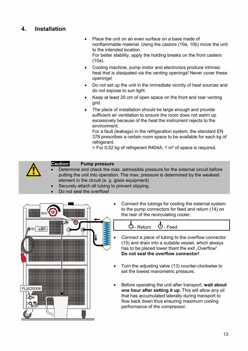
4. Installation • Place the unit on an even surface on a base made of
nonflammable material. Using the castors (10a, 10b) move the unit to the intended location. For better stability, apply the holding breaks on the front casters (10a).
• Cooling machine, pump motor and electronics produce intrinsic heat that is dissipated via the venting openings! Never cover these openings!
• Do not set up the unit in the immediate vicinity of heat sources and do not expose to sun light.
• Keep at least 20 cm of open space on the front and rear venting grid.
• The place of installation should be large enough and provide sufficient air ventilation to ensure the room does not warm up excessively because of the heat the instrument rejects to the environment. For a fault (leakage) in the refrigeration system, the standard EN 378 prescribes a certain room space to be available for each kg of refrigerant. > For 0.52 kg of refrigerant R404A, 1 m³ of space is required.
Caution: Pump pressure • Determine and check the max. admissible pressure for the external circuit before
putting the unit into operation. The max. pressure is determined by the weakest element in the circuit (e. g. glass equipment).
• Securely attach all tubing to prevent slipping. • Do not seal the overflow!
• Connect the tubings for cooling the external system to the pump connectors for feed and return (14) on the rear of the recirculating cooler.
– Return - Feed
• Connect a piece of tubing to the overflow connector (15) and drain into a suitable vessel, which always has to be placed lower thant the exit „Overflow“. Do not seal the overflow connector!
• Turn the adjusting valve (13) counter-clockwise to set the lowest manometric pressure.
• Before operating the unit after transport, wait about
one hour after setting it up. This will allow any oil that has accumulated laterally during transport to flow back down thus ensuring maximum cooling performance of the compressor.
13
¾”
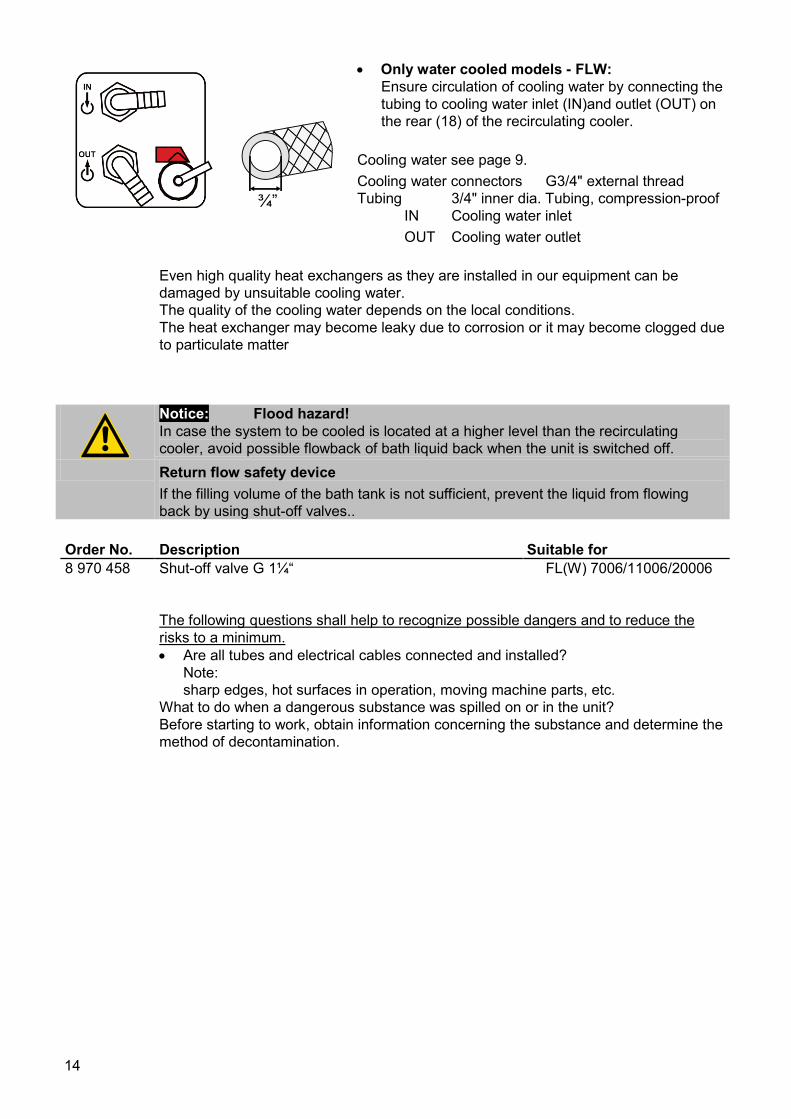
• Only water cooled models - FLW: Ensure circulation of cooling water by connecting the tubing to cooling water inlet (IN)and outlet (OUT) on the rear (18) of the recirculating cooler.
Cooling water see page 9. Cooling water connectors G3/4" external thread Tubing 3/4" inner dia. Tubing, compression-proof IN Cooling water inlet OUT Cooling water outlet
Even high quality heat exchangers as they are installed in our equipment can be damaged by unsuitable cooling water. The quality of the cooling water depends on the local conditions. The heat exchanger may become leaky due to corrosion or it may become clogged due to particulate matter
Notice: Flood hazard! In case the system to be cooled is located at a higher level than the recirculating cooler, avoid possible flowback of bath liquid back when the unit is switched off.
Return flow safety device If the filling volume of the bath tank is not sufficient, prevent the liquid from flowing back by using shut-off valves..
Order No. Description Suitable for 8 970 458 Shut-off valve G 1¼“ FL(W) 7006/11006/20006
The following questions shall help to recognize possible dangers and to reduce the risks to a minimum. • Are all tubes and electrical cables connected and installed?
Note: sharp edges, hot surfaces in operation, moving machine parts, etc.
What to do when a dangerous substance was spilled on or in the unit? Before starting to work, obtain information concerning the substance and determine the method of decontamination.
14
4.1. Tubing
Caution: • Employ suitable connecting tubing. • Make sure that the tubing is securely attached. • Avoid sharp bends in the tubing, and maintain a sufficient distance from
surrounding walls. • Regularly check the tubing for material defects (e.g. for cracks). • Preventive maintenance: Replace the tubing from time to time.
Recommended tubing: Order No. Description Suitable for 8930325 1 m Reinforced tubing 1“ inner dia. (-40 ... +120°C) FL(W) 7006/11006/20006
Tubing insulation 8930425 1 m Insulation, 35 mm inner dia. Reinforced tubing 1“ inner dia.
Tube clamps 8970484 2 Tube clamps, size 5 Reinforced tubing 1“ inner dia.
15
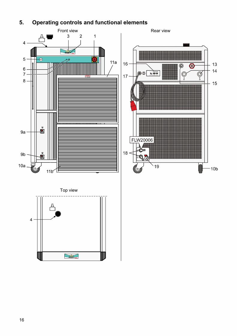
5. Operating controls and functional elements Front view Rear view
Top view
16
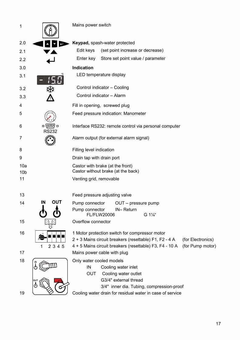
1 ON
Mains power switch
2.0
Keypad, spash-water protected
2.1 Edit keys (set point increase or decrease)
2.2 Enter key Store set point value / parameter
3.0 Indication
3.1 °C
LED temperature display
3.2 Control indicator – Cooling
3.3
Control indicator – Alarm
4 Fill in opening, screwed plug
5
Feed pressure indication: Manometer
6 RS232
Interface RS232: remote control via personal computer
7
Alarm output (for external alarm signal)
8 Filling level indication
9 Drain tap with drain port
10a 10b
Castor with brake (at the front) Castor without brake (at the back)
11 Venting grid, removable
13 Feed pressure adjusting valve
14
Pump connector OUT – pressure pump Pump connector IN– Return FL/FLW20006 G 1¼“
15
Overflow connector
16
1 Motor protection switch for compressor motor 2 + 3 Mains circuit breakers (resettable) F1, F2 - 4 A (for Electronics) 4 + 5 Mains circuit breakers (resettable) F3, F4 - 10 A (for Pump motor)
17 Mains power cable with plug
18 19
Only water cooled models IN Cooling water inlet OUT Cooling water outlet G3/4" external thread 3/4" inner dia. Tubing, compression-proof Cooling water drain for residual water in case of service
17
6. Operating procedures
6.1. Bath fluids
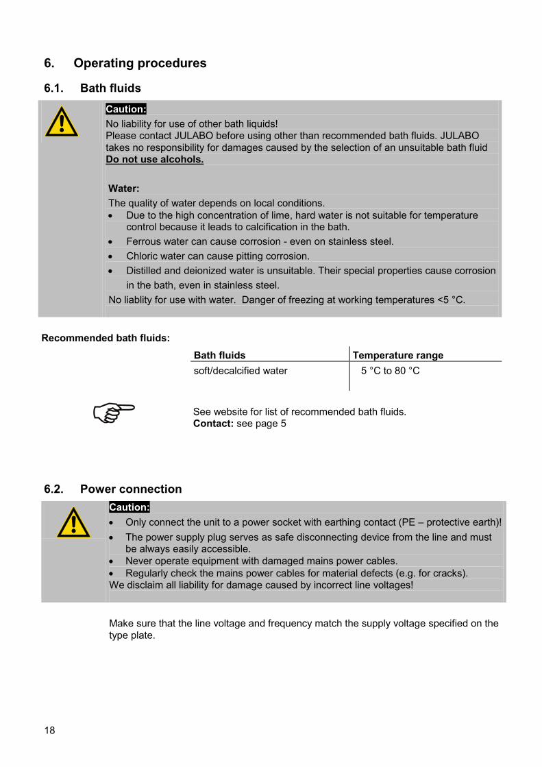
Caution: No liability for use of other bath liquids! Please contact JULABO before using other than recommended bath fluids. JULABO takes no responsibility for damages caused by the selection of an unsuitable bath fluid Do not use alcohols. Water: The quality of water depends on local conditions. • Due to the high concentration of lime, hard water is not suitable for temperature
control because it leads to calcification in the bath. • Ferrous water can cause corrosion - even on stainless steel. • Chloric water can cause pitting corrosion. • Distilled and deionized water is unsuitable. Their special properties cause corrosion
in the bath, even in stainless steel. No liablity for use with water. Danger of freezing at working temperatures <5 °C.
Recommended bath fluids: Bath fluids Temperature range soft/decalcified water 5 °C to 80 °C
See website for list of recommended bath fluids. Contact: see page 5
6.2. Power connection
Caution: • Only connect the unit to a power socket with earthing contact (PE – protective earth)! • The power supply plug serves as safe disconnecting device from the line and must
be always easily accessible. • Never operate equipment with damaged mains power cables. • Regularly check the mains power cables for material defects (e.g. for cracks). We disclaim all liability for damage caused by incorrect line voltages!
Make sure that the line voltage and frequency match the supply voltage specified on the
type plate.
18
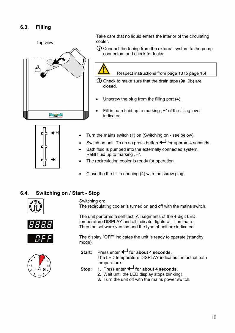
6.3. Filling
Top view
Take care that no liquid enters the interior of the circulating cooler. Connect the tubing from the external system to the pump
connectors and check for leaks
Respect instructions from page 13 to page 15!
Check to make sure that the drain taps (9a, 9b) are closed.
• Unscrew the plug from the filling port (4).
• Fill in bath fluid up to marking „H“ of the filling level
indicator.
H
L
• Turn the mains switch (1) on (Switching on - see below)
• Switch on unit. To do so press button for approx. 4 seconds. • Bath fluid is pumped into the externally connected system.
Refill fluid up to marking „H“. • The recirculating cooler is ready for operation. • Close the the fill in opening (4) with the screw plug!
6.4. Switching on / Start - Stop ON
Switching on: The recirculating cooler is turned on and off with the mains switch. The unit performs a self-test. All segments of the 4-digit LED temperature DISPLAY and all indicator lights will illuminate. Then the software version and the type of unit are indicated. The display "OFF" indicates the unit is ready to operate (standby mode).
60
30
15454 s
Start: Press enter for about 4 seconds. The LED temperature DISPLAY indicates the actual bath temperature.
Stop: 1. Press enter for about 4 seconds. 2. Wait until the LED display stops blinking! 3. Turn the unit off with the mains power switch.
19
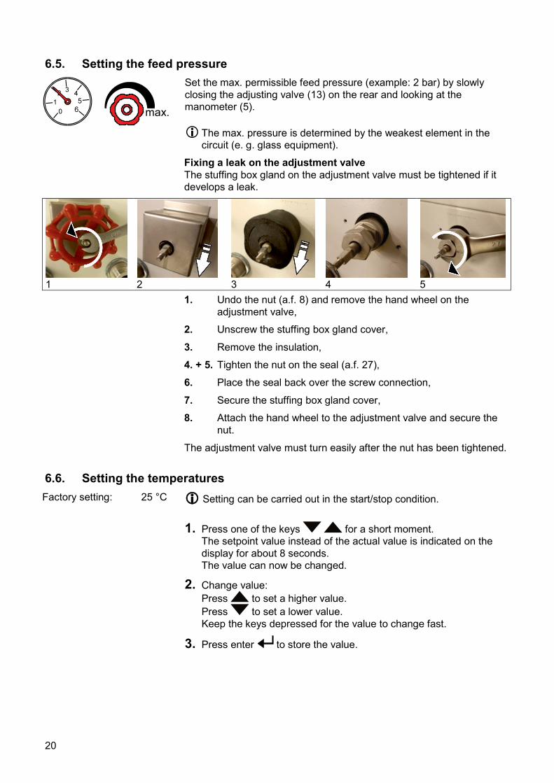
6.5. Setting the feed pressure
max.
Set the max. permissible feed pressure (example: 2 bar) by slowly closing the adjusting valve (13) on the rear and looking at the manometer (5). The max. pressure is determined by the weakest element in the
circuit (e. g. glass equipment). Fixing a leak on the adjustment valve
The stuffing box gland on the adjustment valve must be tightened if it develops a leak.
1
2
3
4
5
1. Undo the nut (a.f. 8) and remove the hand wheel on the adjustment valve,
2. Unscrew the stuffing box gland cover,
3. Remove the insulation,
4. + 5. Tighten the nut on the seal (a.f. 27),
6. Place the seal back over the screw connection,
7. Secure the stuffing box gland cover,
8. Attach the hand wheel to the adjustment valve and secure the nut.
The adjustment valve must turn easily after the nut has been tightened.
6.6. Setting the temperatures Factory setting: 25 °C
Setting can be carried out in the start/stop condition.
1. Press one of the keys for a short moment. The setpoint value instead of the actual value is indicated on the display for about 8 seconds. The value can now be changed.
2. Change value: Press to set a higher value. Press to set a lower value. Keep the keys depressed for the value to change fast.
3. Press enter to store the value.
20
6.7. AUTOSTART ON / OFF The recirculating cooler has been configured and supplied by JULABO
according to N.A.M.U.R. recommendations. This means for the start mode, that the unit must enter a safe operating state after a power failure (non-automatic start mode). This safe operating state is indicated by „OFF“ on the LED temperature display. A complete shutdown of the main functional elements such as compressor and circulating pump is effected simultaneously. If such a safety standard is not required, the AUTOSTART function (automatic start mode) may be activated, thus allowing the start of the circulator directly by pressing the mains power switch
Keep depressed enter and turn on the unit with the mains power switch. For a short while the LED DISPLAY indicates the effective start mode:
AUTOSTART on. AUTOSTART off.
Warning: For supervised or unsupervised operation with the AUTOSTART function, avoid any hazardous situation to persons or property. The recirculating cooler does no longer conform to N.A.M.U.R. recommendations.
6.8. Remote control: activate – deactivate
(Interface OFF)
(Interface On)
The recirculating cooler is to be prepared for remote control by a personal computer via the serial interface RS232. Set the interface item from >IOFF< to >ION<.
Remote control: activate – deactivate:
• Switch off recirculating cooler by pressing the mains switch and wait approx. 5 seconds.
• Keep depressed the keys and enter simultaneously and turn on the unit with the mains power switch.
>I OFF< No remote control via RS232 (Factory setting)
>I On< Remote control via RS232 The software version and the type of unit is indicated
(see example on the left). The display "rOFF" indicates the unit is ready to be operated via remote control.
21
7. Safety installations
7.1. Excess temperature protection
+
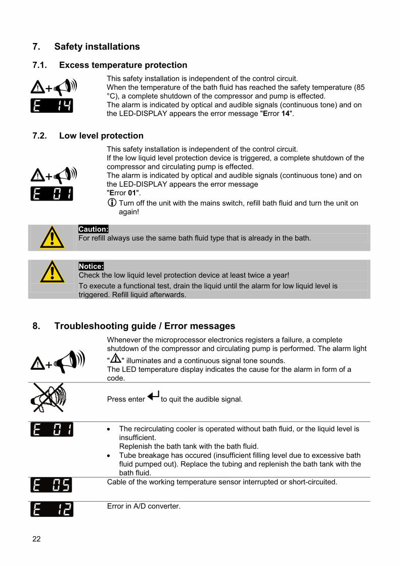
This safety installation is independent of the control circuit. When the temperature of the bath fluid has reached the safety temperature (85 °C), a complete shutdown of the compressor and pump is effected. The alarm is indicated by optical and audible signals (continuous tone) and on the LED-DISPLAY appears the error message "Error 14".
7.2. Low level protection
+
This safety installation is independent of the control circuit. If the low liquid level protection device is triggered, a complete shutdown of the compressor and circulating pump is effected. The alarm is indicated by optical and audible signals (continuous tone) and on the LED-DISPLAY appears the error message "Error 01". Turn off the unit with the mains switch, refill bath fluid and turn the unit on
again!
Caution: For refill always use the same bath fluid type that is already in the bath.
Notice: Check the low liquid level protection device at least twice a year! To execute a functional test, drain the liquid until the alarm for low liquid level is triggered. Refill liquid afterwards.
8. Troubleshooting guide / Error messages
+ Whenever the microprocessor electronics registers a failure, a complete shutdown of the compressor and circulating pump is performed. The alarm light " " illuminates and a continuous signal tone sounds. The LED temperature display indicates the cause for the alarm in form of a code.
Press enter to quit the audible signal.
• The recirculating cooler is operated without bath fluid, or the liquid level is
insufficient. Replenish the bath tank with the bath fluid.
• Tube breakage has occured (insufficient filling level due to excessive bath fluid pumped out). Replace the tubing and replenish the bath tank with the bath fluid.
Cable of the working temperature sensor interrupted or short-circuited.
Error in A/D converter.
22
The return temperature is above the switch-off value of the high temperature protection (85°C). Check dimensioning of application. Use a stronger recirculating cooler if necessary.
• The motor protection switch for the compressor motor is off. Set motor
protection switch to >1< . Check the fuses. • The pressure sensor of low pressure side (evaporation pressure) is faulty,
short-circuited or has a line interruption. Have the repair done by a specialist.
• The motor protection switch for the compressor motor is off. Set motor
protection switch to >1< . Check the fuses. • The pressure sensor of high pressure side is faulty, short-circuited or has a
line interruption. Have the repair done by a specialist.
The suction gas temperature sensor is faulty, short-circuited or has a line interruption. Have the repair done by a specialist.
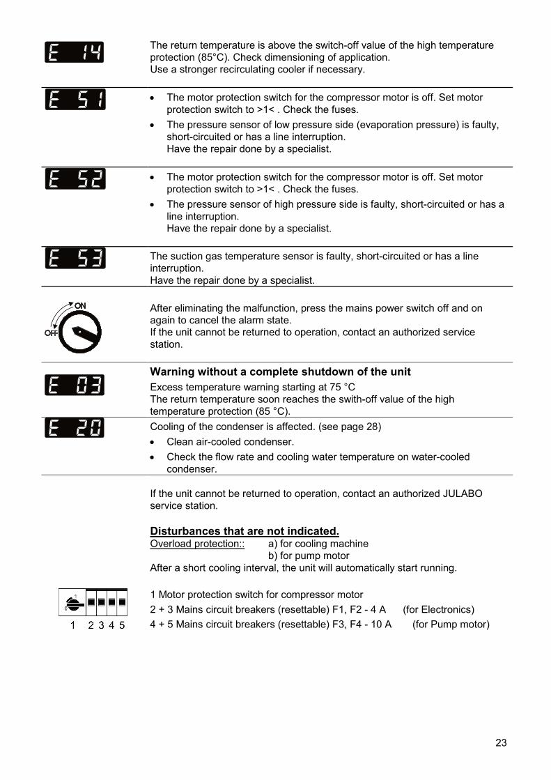
After eliminating the malfunction, press the mains power switch off and on again to cancel the alarm state. If the unit cannot be returned to operation, contact an authorized service station.
Warning without a complete shutdown of the unit Excess temperature warning starting at 75 °C The return temperature soon reaches the swith-off value of the high temperature protection (85 °C).
Cooling of the condenser is affected. (see page 28) • Clean air-cooled condenser. • Check the flow rate and cooling water temperature on water-cooled
condenser.
If the unit cannot be returned to operation, contact an authorized JULABO service station.
Disturbances that are not indicated. Overload protection:: a) for cooling machine b) for pump motor After a short cooling interval, the unit will automatically start running.
1 Motor protection switch for compressor motor 2 + 3 Mains circuit breakers (resettable) F1, F2 - 4 A (for Electronics) 4 + 5 Mains circuit breakers (resettable) F3, F4 - 10 A (for Pump motor)
23
9. Electrical connections
Notice: Use shielded cables only. The shield of the connecting cable is electrically connected to the plug housing. The unit ensures safe operation if connecting cables with a maximum length of 3 m are used. The use of longer cables does not affect proper performance of the unit, however external interferences may have a negative impact on safe operation.
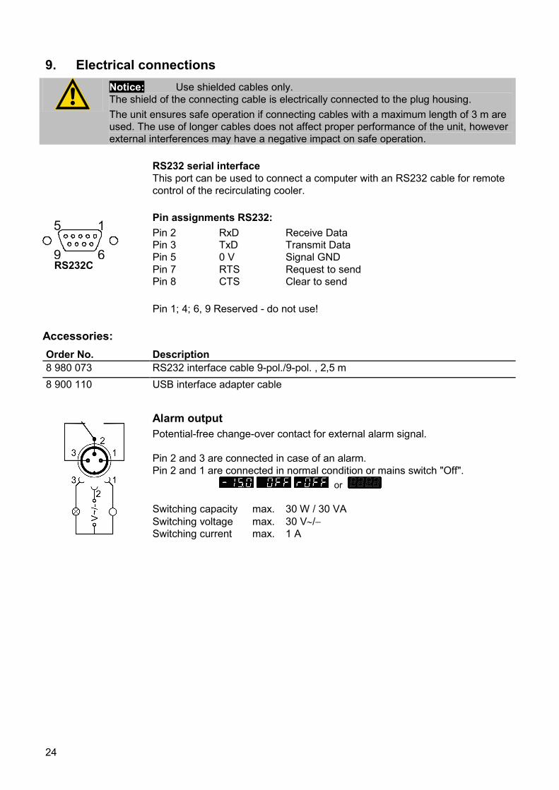
RS232 serial interface
This port can be used to connect a computer with an RS232 cable for remote control of the recirculating cooler.
9 6
5 1
RS232C
Pin assignments RS232: Pin 2 RxD Receive Data Pin 3 TxD Transmit Data Pin 5 0 V Signal GND Pin 7 RTS Request to send Pin 8 CTS Clear to send Pin 1; 4; 6, 9 Reserved - do not use!
Accessories: Order No. Description 8 980 073 RS232 interface cable 9-pol./9-pol. , 2,5 m 8 900 110 USB interface adapter cable
Alarm output Potential-free change-over contact for external alarm signal. Pin 2 and 3 are connected in case of an alarm. Pin 2 and 1 are connected in normal condition or mains switch "Off". or Switching capacity max. 30 W / 30 VA Switching voltage max. 30 V∼/− Switching current max. 1 A
24
10. Remote control
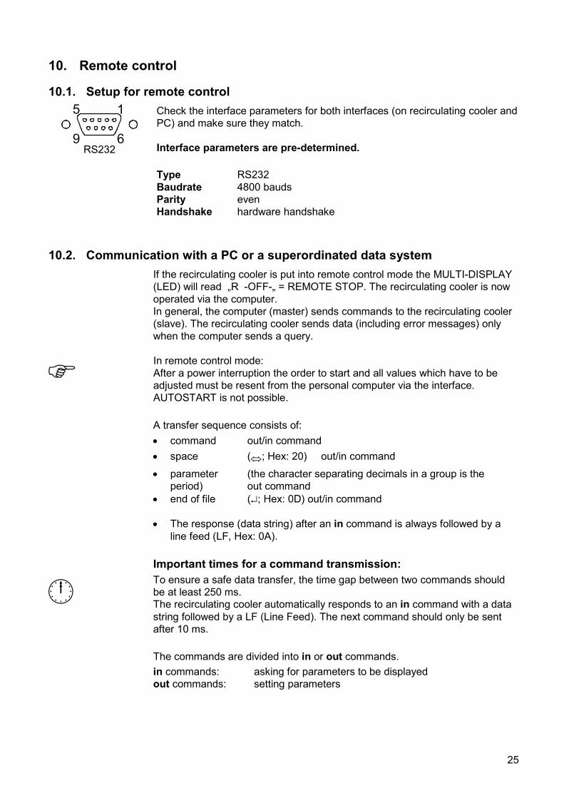
10.1. Setup for remote control
9 6
5 1
RS232
Check the interface parameters for both interfaces (on recirculating cooler and PC) and make sure they match. Interface parameters are pre-determined.
Type RS232 Baudrate 4800 bauds Parity even Handshake hardware handshake
10.2. Communication with a PC or a superordinated data system
If the recirculating cooler is put into remote control mode the MULTI-DISPLAY (LED) will read „R -OFF-„ = REMOTE STOP. The recirculating cooler is now operated via the computer. In general, the computer (master) sends commands to the recirculating cooler (slave). The recirculating cooler sends data (including error messages) only when the computer sends a query.
In remote control mode: After a power interruption the order to start and all values which have to be adjusted must be resent from the personal computer via the interface. AUTOSTART is not possible.
A transfer sequence consists of: • command out/in command • space (⇔; Hex: 20) out/in command
• parameter (the character separating decimals in a group is the period) out command
• end of file (↵; Hex: 0D) out/in command • The response (data string) after an in command is always followed by a
line feed (LF, Hex: 0A).
Important times for a command transmission:
To ensure a safe data transfer, the time gap between two commands should be at least 250 ms. The recirculating cooler automatically responds to an in command with a data string followed by a LF (Line Feed). The next command should only be sent after 10 ms.
The commands are divided into in or out commands. in commands: asking for parameters to be displayed out commands: setting parameters
25
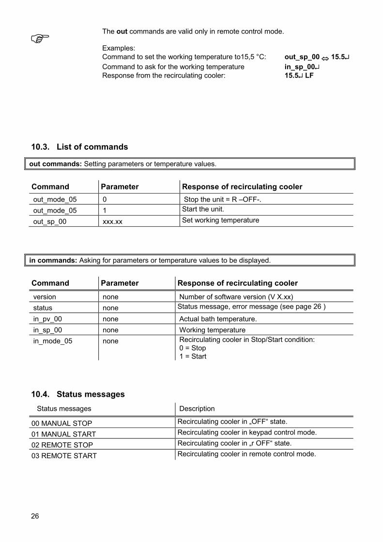
The out commands are valid only in remote control mode. Examples: Command to set the working temperature to15,5 °C: out_sp_00 ⇔ 15.5↵ Command to ask for the working temperature in_sp_00↵ Response from the recirculating cooler: 15.5↵ LF
10.3. List of commands
out commands: Setting parameters or temperature values.
Command Parameter Response of recirculating cooler out_mode_05 0 Stop the unit = R –OFF-. out_mode_05 1 Start the unit.
out_sp_00 xxx.xx Set working temperature
in commands: Asking for parameters or temperature values to be displayed.
Command Parameter Response of recirculating cooler
version none Number of software version (V X.xx) status none Status message, error message (see page 26 )
in_pv_00 none Actual bath temperature. in_sp_00 none Working temperature in_mode_05 none Recirculating cooler in Stop/Start condition:
0 = Stop 1 = Start
10.4. Status messages Status messages Description
00 MANUAL STOP Recirculating cooler in „OFF“ state.
01 MANUAL START Recirculating cooler in keypad control mode.
02 REMOTE STOP Recirculating cooler in „r OFF“ state.
03 REMOTE START Recirculating cooler in remote control mode.
26
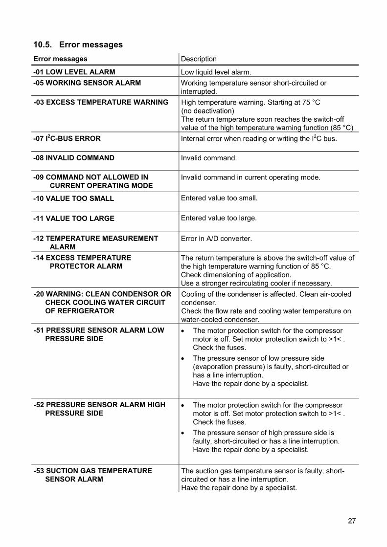
10.5. Error messages Error messages Description
-01 LOW LEVEL ALARM Low liquid level alarm. -05 WORKING SENSOR ALARM Working temperature sensor short-circuited or
interrupted. -03 EXCESS TEMPERATURE WARNING High temperature warning. Starting at 75 °C
(no deactivation) The return temperature soon reaches the switch-off value of the high temperature warning function (85 °C)
-07 I2C-BUS ERROR Internal error when reading or writing the I2C bus.
-08 INVALID COMMAND Invalid command.
-09 COMMAND NOT ALLOWED IN CURRENT OPERATING MODE
Invalid command in current operating mode.
-10 VALUE TOO SMALL Entered value too small.
-11 VALUE TOO LARGE Entered value too large.
-12 TEMPERATURE MEASUREMENT ALARM
Error in A/D converter.
-14 EXCESS TEMPERATURE PROTECTOR ALARM
The return temperature is above the switch-off value of the high temperature warning function of 85 °C. Check dimensioning of application. Use a stronger recirculating cooler if necessary.
-20 WARNING: CLEAN CONDENSOR OR CHECK COOLING WATER CIRCUIT OF REFRIGERATOR
Cooling of the condenser is affected. Clean air-cooled condenser. Check the flow rate and cooling water temperature on water-cooled condenser.
-51 PRESSURE SENSOR ALARM LOW PRESSURE SIDE
• The motor protection switch for the compressor motor is off. Set motor protection switch to >1< . Check the fuses.
• The pressure sensor of low pressure side (evaporation pressure) is faulty, short-circuited or has a line interruption. Have the repair done by a specialist.
-52 PRESSURE SENSOR ALARM HIGH
PRESSURE SIDE • The motor protection switch for the compressor
motor is off. Set motor protection switch to >1< . Check the fuses.
• The pressure sensor of high pressure side is faulty, short-circuited or has a line interruption. Have the repair done by a specialist.
-53 SUCTION GAS TEMPERATURE
SENSOR ALARM The suction gas temperature sensor is faulty, short-circuited or has a line interruption. Have the repair done by a specialist.
27
11. Cleaning / repairing the unit
Caution: Always turn off the unit and disconnect the mains cable from the power source before cleaning the unit. Prevent humidity from entering into the circulator. Electrical connections and any other work must be performed by qualified personnel only.
Notice: Risk of hand injuries when mounting the venting grid.
Maintaining the cooling performance
Air cooled models = FL To maintain the full cooling performance, clean the condenser from time to time. • Switch off the unit, disconnect mains power cable.
• Hold the venting grid, pull out and remove.
• Clean the ribbed condenser with a vacuum cleaner.
• Replace the venting grid.
• Switch on the unit.
The following service procedures are to be carried out only by qualified service personnel.
In order to maintain a good condition of the cooling compressor, the dirt pan in the cooling water inlet should be cleaned in regular intervals. • Switch the unit off, disconnect the power plug. • Interrupt the cooling water inlet. • Loosen the screws at the back and remove right side panel.
• Dirt collects behind the lock screw of the dirt trap. Remove
lock screw. • Remove the dirt by opening the water input for a short
moment (rinse). • Return and fasten lock screw to dirt trap. • Open cooling water inlet and check screw coupling for leak
tightness. • Replace right side panel. • The unit is ready to operate again.
28
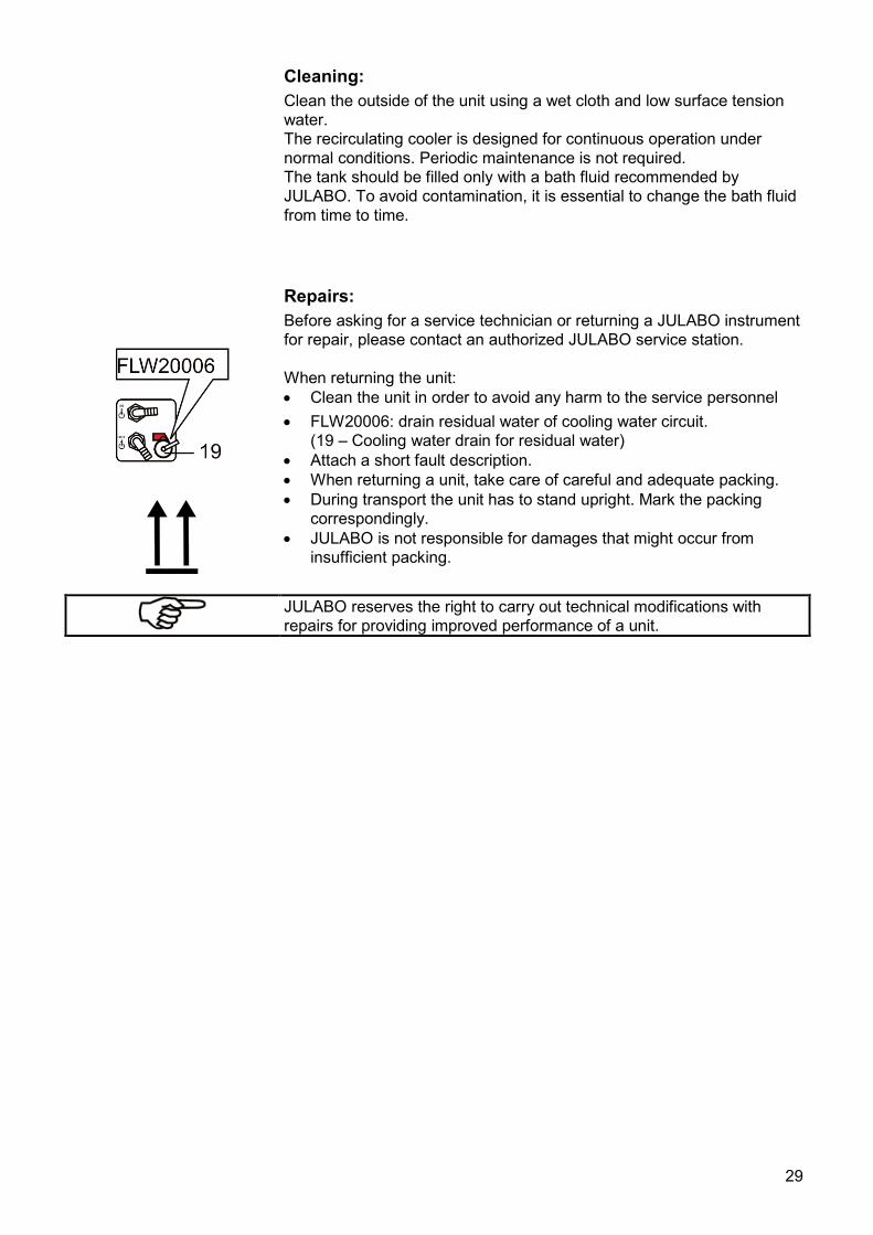
Cleaning: Clean the outside of the unit using a wet cloth and low surface tension water. The recirculating cooler is designed for continuous operation under normal conditions. Periodic maintenance is not required. The tank should be filled only with a bath fluid recommended by JULABO. To avoid contamination, it is essential to change the bath fluid from time to time. Repairs: Before asking for a service technician or returning a JULABO instrument for repair, please contact an authorized JULABO service station. When returning the unit: • Clean the unit in order to avoid any harm to the service personnel • FLW20006: drain residual water of cooling water circuit.
(19 – Cooling water drain for residual water) • Attach a short fault description. • When returning a unit, take care of careful and adequate packing. • During transport the unit has to stand upright. Mark the packing
correspondingly. • JULABO is not responsible for damages that might occur from
insufficient packing.
JULABO reserves the right to carry out technical modifications with repairs for providing improved performance of a unit.
29
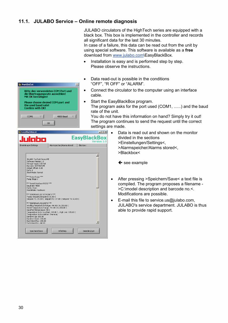
11.1. JULABO Service – Online remote diagnosis
JULABO circulators of the HighTech series are equipped with a black box. This box is implemented in the controller and records all significant data for the last 30 minutes. In case of a failure, this data can be read out from the unit by using special software. This software is available as a free download from www.julabo.com\EasyBlackBox. • Installation is easy and is performed step by step.
Please observe the instructions.
• Data read-out is possible in the conditions “OFF”, “R OFF” or “ALARM”.
• Connect the circulator to the computer using an interface cable.
• Start the EasyBlackBox program. The program asks for the port used (COM1, ......) and the baud rate of the unit. You do not have this information on hand? Simply try it out! The program continues to send the request until the correct settings are made.
• Data is read out and shown on the monitor divided in the sections >Einstellungen/Settings<, >Alarmspeicher/Alarms stored<, >Blackbox< see example
• After pressing >Speichern/Save< a text file is compiled. The program proposes a filename - >C:\model description and barcode no.<. Modifications are possible.
• E-mail this file to [email protected], JULABO's service department. JULABO is thus able to provide rapid support.
30
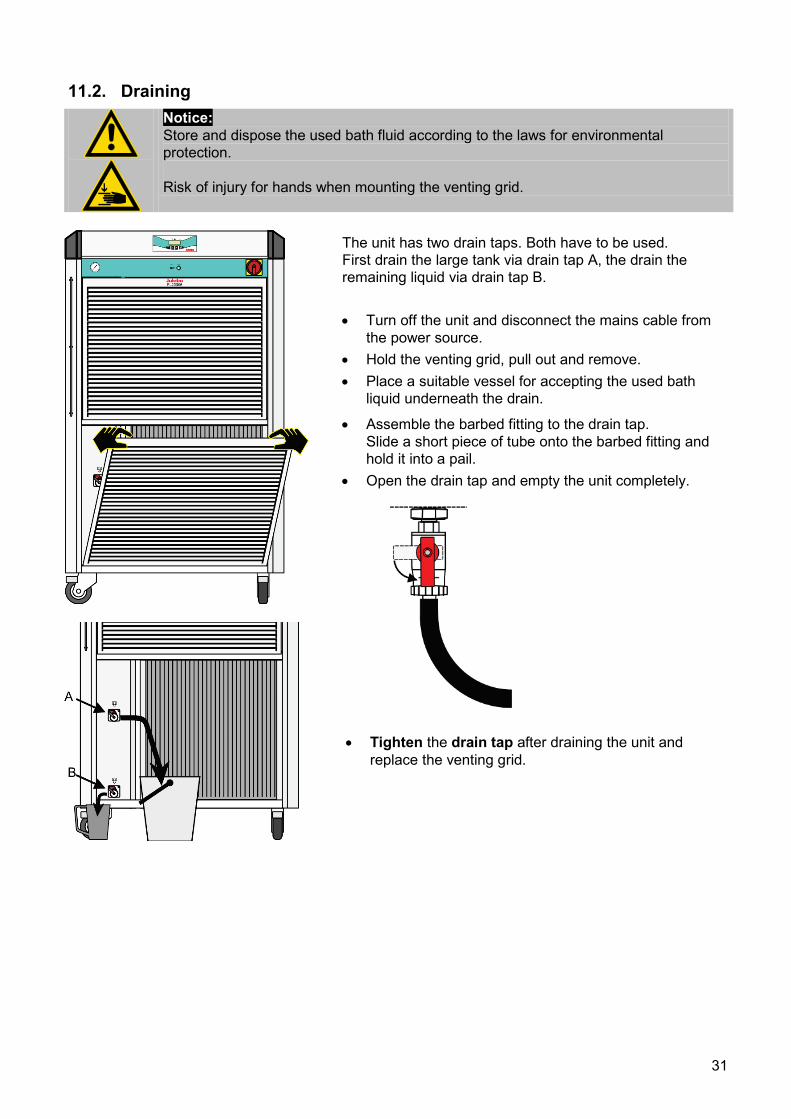
11.2. Draining
Notice: Store and dispose the used bath fluid according to the laws for environmental protection. Risk of injury for hands when mounting the venting grid.
The unit has two drain taps. Both have to be used. First drain the large tank via drain tap A, the drain the remaining liquid via drain tap B. • Turn off the unit and disconnect the mains cable from
the power source. • Hold the venting grid, pull out and remove. • Place a suitable vessel for accepting the used bath
liquid underneath the drain.
• Assemble the barbed fitting to the drain tap. Slide a short piece of tube onto the barbed fitting and hold it into a pail.
• Open the drain tap and empty the unit completely.
• Tighten the drain tap after draining the unit and
replace the venting grid.
31
12. WARRANTY PROVISIONS The following Warranty Provisions shall apply to products sold in North America by Julabo (“Seller”) to the entity shown as buyer (“Buyer”) on Seller’s invoice.
1. Initial Warranty. Upon Seller’s receipt of payment in full for the products and subject to Buyer’s compliance with the terms of sale and any other agreement with Seller relating to the products, Seller warrants to the Buyer that the products manufactured by the Seller are free from defects in material and workmanship for a period not to exceed two (2) years or ten thousand (10,000) hours of operation, whichever comes first, from the date the product is shipped by Seller to Buyer (the “Initial Warranty”).
2. EXCLUSION OF ALL OTHER EXPRESS WARRANTIES; EXCLUSION OF ALL IMPLIED WARRANTIES. OTHER THAN THE INITIAL WARRANTY, NO OTHER EXPRESS WARRANTIES ARE MADE. ALL IMPLIED WARRANTIES OF EVERY TYPE AND KIND, INCLUDING BUT NOT LIMITED TO ANY IMPLIED WARRANTY OF MERCHANTABILITY OR FITNESS FOR A PARTICULAR PURPOSE OR USE, ARE EXCLUDED IN ALL RESPECTS AND FOR ALL PURPOSES. SELLER DISCLAIMS AND MAKES NO IMPLIED WARRANTIES WHATSOEVER.
3. Exclusions. The Initial Warranty does not include damage to the product resulting from
accident, misuse, improper installation or operation, unauthorized or improper repair, replacement or alteration (including but not limited to repairs, replacements, or alterations made or performed by persons other than Seller’s employees or authorized representatives), failure to provide or use of improper maintenance, unreasonable use or abuse of the product, or failure to follow written installation or operating instructions. Buyer must return the product’s record of purchase to the Seller or one of Seller’s authorized representatives within thirty (30) days of the date the product is shipped by Seller to Buyer in order to make a claim under the Initial Warranty. Notwithstanding anything contained herein to the contrary, all glassware, including but not limited to reference thermometers, are expressly excluded from the Initial Warranty.
4. Buyer’s sole remedies; Limitations on Seller’s Liability. Buyer’s sole and exclusive remedy
under the Initial Warranty is strictly limited, in Seller’s sole discretion, to either: (i) repairing defective parts; or (ii) replacing defective parts. In either case, the warranty period for the product receiving a repaired or replaced part pursuant to the terms of the Initial Warranty shall not be extended. All repairs or replacements performed by Seller pursuant to these Warranty Provisions shall be performed at Seller’s facility in Allentown, Pennsylvania, U.S.A. or at the facility of an authorized representative of Seller, which location shall be determined by Seller in its sole discretion; provided, however, that Seller may, in its sole discretion perform such repairs or replacements at Buyer’s facility in which case Buyer shall pay Seller’s travel, living and related expenses incurred by Seller in performing the repairs or replacements at Buyer’s facility. As a condition precedent to Seller’s obligation to repair or replace a product part under the Initial Warranty, Buyer shall (i) promptly notify Seller in writing of any such defect; (ii) shall have returned the product’s record of purchase to Seller or to one of Seller’s authorized representatives within thirty (30) days of the date the product is delivered to Buyer; and (iii) assist Seller in all respects in its attempts to determine the legitimacy and basis of any claims made by or on behalf of Buyer including but not limited to providing Seller with access to the product to check operating conditions. If Buyer does not provide such written notice to Seller within the Initial Warranty period or fails to return the product’s record of purchase as set forth above, Seller shall have no further liability or obligation to Buyer therefore. In no event shall Seller’s liability under the Initial Warranty exceed the original purchase price of the product which is the subject of the alleged defect.
5. THE REMEDIES PROVIDED IN THE INITIAL WARRANTY ARE THE SOLE AND EXCLUSIVE
REMEDIES AVAILABLE TO THE BUYER. NOTWITHSTANDING ANYTHING TO THE CONTRARY CONTAINED HEREIN, AND EVEN IF THE SOLE AND EXCLUSIVE REMEDIES FAIL OF THEIR ESSENTIAL PURPOSE FOR ANY REASON WHATSOEVER, IN NO EVENT SHALL SELLER BE LIABLE FOR BUYER’S MANUFACTURING COSTS, LOST PROFITS, GOODWILL, OR ANY OTHER SPECIAL, INDIRECT, PUNITIVE,
32
INCIDENTAL OR CONSEQUENTIAL DAMAGES TO BUYER OR ANY THIRD PARTY AND ALL SUCH DAMAGES ARE HEREBY DISCLAIMED.
6. Assignment. Buyer shall not assign any of its rights or obligations hereunder without the prior
written approval of Seller; provided, however, that if Buyer is a distributor of Seller, the rights and obligations of Buyer under these Warranty Provisions shall inure to the benefit of and be binding upon Buyer’s customers who provide the product’s proof of purchase to Seller pursuant to the terms set forth herein. Seller may assign any or all of its rights or obligations hereunder without Buyer’s prior consent.
7. Governing Law. The Warranty Provisions and all questions relating to their validity, interpretation, performance, and enforcement shall be construed in accordance with, and shall be governed by, the substantive laws of the Commonwealth of Pennsylvania without regard to its principles of conflicts of law.
8. Waiver. Any failure of the part of Seller to insist on strict compliance with the Warranty Provisions shall no way constitute a waiver of such right. No claim or rights arising out of a breach of the Warranty Provisions by Buyer may be discharged in whole or in part by a waiver of the claim or right, unless the waiver is in writing signed by an authorized representative of Seller. Seller’s waiver or acceptance of any breach by Buyer of any provisions of the Warranty Provisions shall not constitute a waiver of or an excuse for nonperformance as to any other provision of the Warranty Provisions nor as to any prior or subsequent breach of the same provision.
9. Freight. Buyer will arrange and pay for shipping and handling charges for the unit to be returned to the Seller.Seller will arrange and pay for shipping and handling for the return of the unit to the Buyer.
33
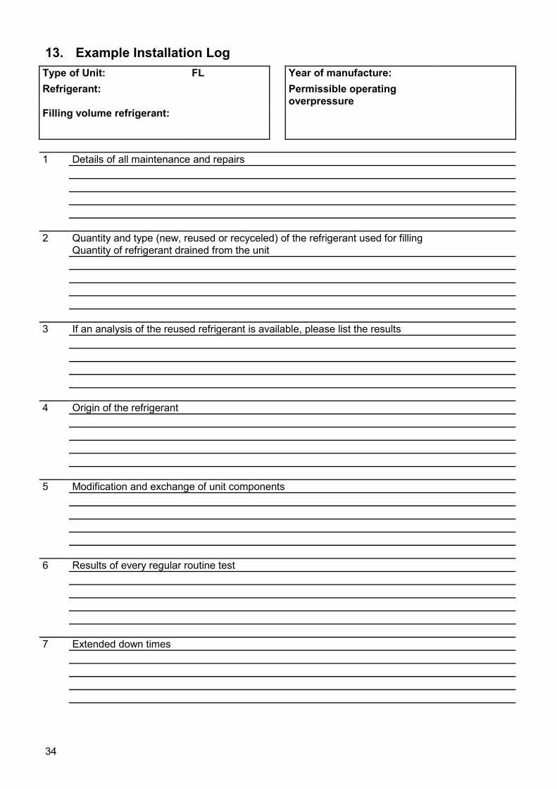
13. Example Installation Log Type of Unit: FL Year of manufacture: Refrigerant: Permissible operating
overpressure
Filling volume refrigerant: 1 Details of all maintenance and repairs
2 Quantity and type (new, reused or recyceled) of the refrigerant used for filling Quantity of refrigerant drained from the unit
3 If an analysis of the reused refrigerant is available, please list the results
4 Origin of the refrigerant
5 Modification and exchange of unit components
6 Results of every regular routine test
7 Extended down times
34