Embed Size (px)
Citation preview
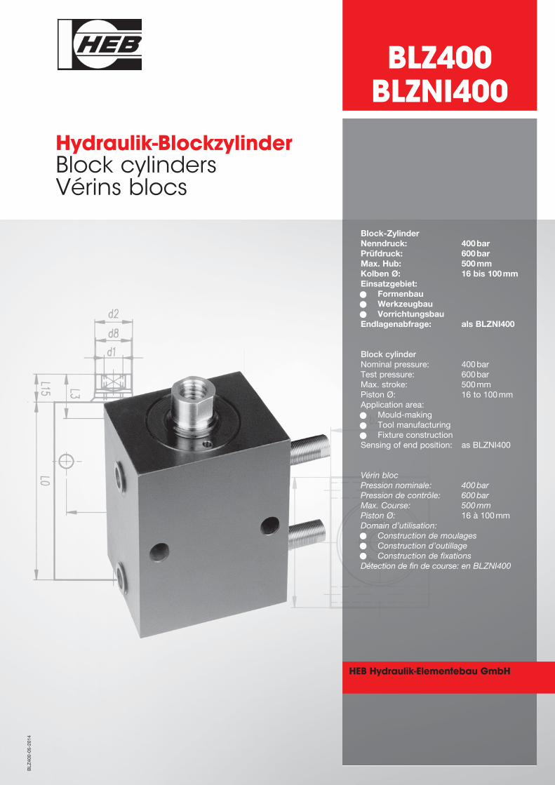
Block-ZylinderNenndruck: 400barPrüfdruck: 600barMax. Hub: 500mmKolben Ø: 16 bis 100mmEinsatzgebiet:• Formenbau• Werkzeugbau• VorrichtungsbauEndlagenabfrage: als BLZNI400
Block cylinderNominal pressure: 400barTest pressure: 600barMax. stroke: 500mm Piston Ø: 16 to 100mmApplication area:• Mould-making• Tool manufacturing• Fixture constructionSensing of end position: as BLZNI400
Vérin blocPression nominale: 400barPression de contrôle: 600barMax. Course: 500mmPiston Ø: 16 à 100mmDomain d’utilisation: • Construction de moulages• Construction d’outillage• Construction de fixationsDétection de fin de course: en BLZNI400
Hydraulik-BlockzylinderBlock cylindersVérins blocs
BLZ
400-05-2014
BLZ400BLZNI400
HEB Hydraulik-Elementebau GmbH
Allgemeine Beschreibungund Hinweise
Bauweise:
Blockzylinder mit sehr kleinenBaulängen
Kolbenstangenlauffläche hartver-chromt, geschliffen und poliert
Kolben-Ø und Kolbenstangen-Ønach DIN/ISO 3320
Hübe (Hubtoleranz DIN/ISO 2768m)nach Kundenwunsch 0,1mm bis500mm oder Standardhübe (S.4)
Bei großen Hublängen ist die maxi-mal mögliche Hublänge zu beachten
Abfrage:
Der BLZNI400 ist serienmäßig soausgelegt, dass nur bei Erreichender Hubendlage ein Schaltimpulsabgegeben wird (d.h. der Zylindermuss den angegebenen Hub voll-ständig fahren können)
Eine Schaltpunktvorverlagerungstangen- und/oder kolbenseitig umbis zu 5mm auf Kundenwunschohne Maßänderung möglich (d.h.Zylinderhub wird zwar voll ausge-nutzt, der Schaltimpuls stehtjedoch entsprechend dem vorver-legten Schaltpunkt schon vorherzur Verfügung).Durch folgenden Zusatz zur Bestell-bezeichnung kann eine gewünschteSchaltpunktverlagerung kenntlichgemacht werden:SPS3* = Schaltpunkt stangenseitig3mm vor EndlageSPK3* = Schaltpunkt kolbenseitig3mm vor EndlageSPB3* = Schaltpunkt beidseitig3mm vor Endlage(* Schaltpunktverlagerung 1-5mmeinsetzen)
Die Wiederholgenauigkeit liegt bei0,05mm
Zur Vermeidung von Fehlschaltun-gen (Hysterese) ist ein Mindesthubvon 3mm einzuhalten
Ein nachträgliches Verstellen deseinmal festgelegten Schaltpunktesist nicht möglich
2
General description and informations
Construction:
Block cylinders with very small lengths
Piston-rod hard-chrome plated, ground and polished
Piston-Ø and Piston-rod-Ø accordingto DIN/ISO 3320
Strokes (Stroke tolerance according toDIN/ISO 2768m) according to custo-mer request 0,1mm to 500mm or stan-dard strokes (p.4)
With large strokes consider the maxi-mum stroke
Query:
The BLZNI400 is equiped in series sothat a sensing impulse is only given if itreaches the end of stroke (that means,the cylinder must be able to executethe indicated total stroke)
The sensing point shift piston-rodand/or piston side by up to 5mm onrequest without dimensional change ispossible (that means, in this case, thecylinder stroke is fully utilized but cor-responding to the displaced sensingpoint, the sensing impulse is availablebefore).A displacement of the sensing pointcan be marked by the following sup-plement:SPS3* = sensing point rod-side 3mmbefore stroke endSPK3* = sensing point piston-side3mm before stroke endSPB3* = sensing point both-side 3mmbefore stroke end(* enter the desired displacement of thesensing point from 1-5mm)
The repeat accuracy is 0,05mm
To avoid faulty switching (hysteresis) aminimum stroke of 3mm has to beconsidered
The once fixed sensing point cannot bedisplaced subsequently
Description générale et desinformations
Construction:
Vérins-bloc avec des longueurs trèspetites
Tige de piston chromées durement,meulées et polies
Ø-piston et Ø-tige de piston selonDIN/ISO 3320
Course (Tolérance de course confor-mes à la norme DIN/ISO 2768m) selonla demande du client 0,1mm à 500mmou course standardisées (p.4)
Avec de grandes courses considérer lemaximum course est observée
Détection:
Le BLZNI400 est équipé en série desorte que l'impulsion de détection n'estdonné que si elle atteint la fin de lacourse (ce qui signifie, le cylindre doitêtre capable d'exécuter le coup indi-quée au total)
Un déplacement du point de détectioncôté tige et/ou côté piston est possiblejusqu´à 5mm selon le souhait du client (c´est à dire la course du cylindre esten effet entièrement utilisée, maisl´impulsion de détection est disponibledéjà avant correspondant le déplace-ment du point de détection).Si vous souhaitez un déplacement dupoint de commutation il faut ajouter à laréférence de commande une phrasesupplémentaire telle que la suivante:SPS3* = point de détection côté tige3mm avant la fin de courseSPK3* = point de détection côté piston3mm avant la fin de courseSPB3* = point de détection aux deuxcôtés 3mm avant la fin de course(* Entrer dans le déplacement souhaitédu point de détection de 1 à 5mm)
La précision de répétition est de 0,05mm
Pour éviter faux couplage (hystèrèsis) ilfaut observer une course minimale de3mm
Il n'est pas possible de régler le pointde détection aprés qu'il à eté déter-miné une fois
•
•
•
•
•
•
•
•
•
•
BLZ
400
•
•
•
•
•
•
•
BLZ
400
Allgemeine Beschreibungund Hinweise
Kolbengeschwindigkeit:
Für höhere Geschwindigkeiten isteine Änderung der Anschlussgrößenund eine Endlagendämpfung oderexterne Hubbegrenzung notwendig(Bitte kontaktieren Sie uns)
Die Endlagendämpfung mit progres-sivem Übergang in die Dämpfungs-phase ist grundsätzlich ab Kolben-Ø20mm lieferbar
Dichtung:
Die Kolbenstangendichtung bestehtstandardmäßig aus einem PU-Nutring (weitere Dichtungsvariantenauf Anfrage)
Die Kolbendichtung besteht stan-dardmäßig aus PTFE und ist beson-ders reibungsarm, alternativ für sta-tische Dichtheit gibt es eine spezielleDichtung (S35)
Die Standarddichtungen sind fürHydroflüssigkeiten der Typen H, HL,HLP nach DIN 51524 / 51525 und denTemperaturbereich von -20°C bis+90°C geeignet
Beim Betrieb mit anderen Druckflüs-sigkeiten oder höheren Temperatu-ren sind andere Dichtungswerkstoffeerforderlich (bitte beachten Sieunsere Sonderaussattungen oderkontaktieren Sie uns)
Grundsätzlich erhältlich sind verän-derte Bauformen, Zylinder mit Küh-lung sowie Sonderanfertigungennach Kundenwunsch - bitte kontak-tieren Sie uns
3
General description and informations
Piston speed:
For higher speeds is a change ofdimensions of connections and a stro-ke-end damping or external stroke limi-tation are required (please contact us)
The stroke-end damping with progres-sive transition to damping phase avai-lable for piston-Ø above 20mm
Seal:
The piston rod seal typically consists ofa PU-ring in groove (other seals onrequest)
The piston seal typically consists ofPTFE and is extremely low friction, asan alternative for static sealing there isa special seal (S35)
The standard seals are suitable tohydraulic fluids of the type H, HL, HLPaccording to DIN51524/51525 and totemperatures from -20°C to +90°C
For operation with other fluids or highertemperatures, other sealing materialsare required (please note our specialequipment or contact us)
Generally available are altered designs,cylinder with cooling as well as custommade cylinders - please contact us
Description générale et desinformations
Vitesse du piston:
Pour des vitesses supérieures est unchangement de dimensions de conne-xions et un amortissement de fin decourse ou externe limitation de coursesont nécessaires (s'il vous plaît contac-tez-nous)
L´amortissement en fin de course avecsurvenance progressif dans la phased´amortissement est principalementlivrable à partir d´un piston ø 20mm
Joint:
Le joint de tige se compose générale-ment d'un PU-anneau (autres joints surdemande)
Le joint de piston se composegénéralement de PTFE et de frottementextrêmement faible, comme une alter-native pour étanchéité statique est unsceau spécial (S35)
Les joints standard sont concus pourde fluides hydrauliques des types H,HL, HLP conformément aux normesDIN51524/51525 et pour des tempéra-tures de -20°C à +90°C
Pour le fonctionnement avec d'autresfluids hydrauliques ou des températu-res plus élevées, autres matériauxd'étanchéité sont requis (s'il vous plaîtnoter que notre équipement spécial oucontactez-nous)
Généralement disponibles sont modi-fiées conçoit, cylindre à refroidisse-ment ainsi que les bouteilles fabriquéessur mesure - s'il vous plaît contactez-nous
Technische Daten Technical data Caractéristiques techniques
4 BLZ
400
Kolben - Ø mm 16 20 25 32 40 50 63Piston - Ø mm • Ø - piston mm
Baureihe BLZ BLZNI BLZ BLZNI BLZ BLZNI BLZ BLZNI BLZ BLZNI BLZ BLZNI BLZ BLZNI
Construction • Construction Hübe strokes • courses
10 � � � �
15 � � � � � � � � � � � �
20 � � � � � � � � � � � � �
25 � � � � � � � � � � � �
30 � � � � � � � � � � � �
40 � � � � � � � � � � � �
50 � � � � � � � � � � � �
60 � � � � � � �
70 �
80 � � � � �
100 � � � � �
Kurze Lieferzeiten durch Standardhübe Funktionsart 200, 201, 206 gemäß Tabelleund Zwischenhübe beim BLZ400 durch Begrenzungshülsen Short delivery time through standard strokes mode of operation 20, 201, 206 according to tableand intermediate strokes when BLZ400 with limiter sleevesDélai de livraison bref avec courses stadardisées mode de fonctionnement 200, 201, 206 selon tableet entre-courses quand BLZ400 avec douilles de limitation
Kolben - Ø mm 16 20 25 32 40 50 63 80 100Piston - Ø mm • Ø - piston mm
Kolbenstangen - Ø mm 10 12 16 20 25 32 40 50 60
Piston-rod - Ø mm • Ø - tige de piston mm
Kolbenfläche stoßend - cm2 • Piston area pushing - cm2 • Surface de piston poussante - cm2
2,01 3,14 4,91 8,04 12,56 19,63 31,16 50,24 78,50
Kolbenfläche ziehend cm2 • Piston area pulling - cm2 • surface de piston tirante - cm2
1,22 2,00 2,90 4,90 7,65 11,59 18,60 30,61 50,24
Kolbenkraft stoßend - daN • Piston force pushing - daN • Force de piston poussante - daN 100 bar 201 314 491 804 1256 1963 3116 5024 7850 150 bar 301 471 736 1206 1884 2944 4674 7536 11775 200 bar 402 628 982 1608 2512 3926 6232 10048 15700 300 bar 603 942 1473 2412 3768 5889 9348 15072 23550 400 bar 804 1256 1964 3216 5024 7852 12464 20096 31400
Kolbenkraft ziehend - daN • Piston force pulling - daN • Force de piston tirante - daN 100 bar 122 200 290 490 765 1159 1860 3061 5024 150 bar 183 300 439 735 1147 1738 2790 4591 7536 200 bar 244 400 580 980 1530 2318 3720 6122 10048 300 bar 366 600 870 1470 2295 3477 5508 9183 15072 400 bar 488 800 1160 1960 3060 4636 7440 12244 20096
Dämpfungsweg - 7 7 8 8 8 10 11 12Cushioning path • Course d’amortissement
Kolben - Ø mm 16 20 25 32 40 50 63 80 100Piston - Ø mm • Ø - piston mm
• Standardlage der Entlüftungsschrauben Zylinderseite siehe helle Markierung • Standard position of the bleeder screws see the bright marking• Position standard des vis de purge voir le marquage de couleur claire
S5
S7
S9
S13
S14
S35
B1
B1.1
M1.1
Sonderausstattungen Special equipments Equipements optionnels
5BLZ
400
S4.120
S10.120
N2
N4
N2.1
N4.1
Mögliche Lage der EntlüftungsschraubenPosition of the bleeder screwsPosition des vis de purge
1
2 3 4 2 3 3 4 2 3 4 3 4 2 2 4 2 3 4
2 4 2 4 2 4 - 4 2 2 4 2 4
EntlüftungBleedingPurge d'air
BLZ400
BLZNI400
1.1EntlüftungBleedingPurge d'air
1.2EntlüftungBleedingPurge d'air
2 / 2.1 / 3 / 3.1 / 5.1EntlüftungBleedingPurge d'air
4.1 EntlüftungBleedingPurge d'air
6 / 6.1EntlüftungBleedingPurge d'air
6.4 / 6.14EntlüftungBleedingPurge d'air
7 / 7.1EntlüftungBleedingPurge d'air
8 / 8.1EntlüftungBleedingPurge d'air
• Hochhitzebeständige Dichtungen für Hydroflüssigkeiten der Typen H, HL, HLP - DIN 51524/51525
und Temperaturen ab +100°C bis +200°C
High heat-resistant seals for hydraulic fluids type H, HL, HLP – German Standard DIN 51524/51525
and for temperatures from +100°C up to +200°C
Garnitures réstistantes aux températures très élevées pour liquides type H, HL, HLP – DIN 51524/51525
et des températures de +100°C jusqu’ à +200°C
• Beidseitige Entlüftungsschrauben für Schlauchanschluß
Bleed screws on both sides for hose connections
Vis de purge d’air, des deux côtés, pour raccord tuyau
• Vom Standard abweichende Leitungsanschlüsse
Non-standard connections
Raccords tuyaux autres que raccords standards
• Kolbenstangenlauffläche gehärtet und hartverchromt
Piston-rod hardened and hard-chrome plated
Tige de piston trempée et chromée durement
• Kolbenstangen aus V2A, Werkstoff 1.4301, hartverchromt
Piston-rod stainless steal, mat. no. 1.4301, hard-chrome plated
Tige du piston en acier inoxydable, matériau numeró 1.4301, chromée durement
• Kolben statisch dicht
Piston with static sealing effect
Piston avec effet hermétique
• Kolbenstangenende mit Außengewinde
Piston-rod end with externall thread
Fin de la tige de piston avec filet extérieur
• Kolbenstangenende mit Außengewinde nach Kundenwunsch (Bitte L3, L4, d2G angeben)
Piston-rod end with external thread according to the wishes of the customer (please indicate L3, L4, d2G)
Fin de la tige de piston avec filet extérieur selon la demande du client (s'il vous plaît indiquez L3, L4, d2G)
• Kolbenstangenende mit Innengewinde nach Kundenwunsch (Bitte a4, a5, a6 angeben)
Piston-rod end with internal thread according to the wishes of the customer (please indicate a4, a5, a6)
Fin de la tige de piston avec filet intérieur selon la demande du client (s'il vous plaît indiquez a4, a5, a6)
• Nut zur Justierung auf Seite 2 (N2) und/oder auf Seite 4 (N4)
Groove for adjustment on page 2 (N2) and/or on page 4 (N4)
Rainure pour ajustement à la page 2 (N2) et/ou à la page 4 (N4)
• Nut zur Justierung auf Seite 2 (N2) und/oder auf Seite 4 (N4) nach Kundenwunsch (Bitte h, b, t angeben)
Groove for adjustment on page 2 (N2) and/or on page 4 (N4) to the wishes of the customer (Please indicate h, b, t)
Rainure pour ajustement à la page 2 (N2) et/ou à la page 4 (N4) désir du client (S'il vous plait indiquez h, b, t)• Stangenseitiger Zentrierbund
Rod-side with centering collar ZE
Côté tige avec collet de centrage
Näherungsschalter mit Winkelstecker
Proximity sensor with angular plug S4
Détecteur de proximité avec connecteur coudé
• Näherungsschalter mit Geradstecker
Proximity sensor with straight plug S10
Détecteur de proximité avec connecteur droit
• Näherungsschalter und Stecker für Temperaturen bis +120°C
Proximity sensor and plug for temperatures up to +120°C
Détecteur de proximité é connecteur pour des températures jusqu’ à +120°C
Schalthysterese Switching hysteresis Course différentielle ≤ 15 %
Betriebsspannung Supply voltage Tension d’emploi 10 . . . 30 VDC
Inkl. Restwelligkeit Incl. ripple Ondulation résiduelle ≤ 15 %
Strombelastbarkeit Load current Courant admissible 130 mA
Schaltfrequenz max Switching frequency max Fréquence max de commutation 400 Hz
Spannungsabfall Voltage drop Chute de tension 2,5V
Stromaufnahme ohne Last Current consumption without load Consommation de courant sans charge 25 mA
kurzschlußfest Short cicuit protected Protection contre les courtscircuits ja / yes / oui
Gehäusewerkstoff Housing material Matérial du boîtier No 1.4104
Umgebungstemperatur Ambient operation temperature Témperature d’emploi -25° C . . . +70° C
Anschlußart Connection type Raccordement Pu-Flex-Kabel, 3 x 0,14mm2 x 3000 mm
Steckverbinder (s. u.) Plug connection (see below) Connecteur (voir ci-dessous)
Hochdruckfest bis High pressure rated to 500 bar Résistant aux pression de jusq’à 500 bar an aktiver Fläche of the active surface 500 bar au droit de la face sensible
Schutzart IP 68 Protection class IP 68 of the Degré de protection IP 68 au droitan aktiver Fläche active surface de la face sensible
PNP-Schließer/plusschaltend –
PNP-Normally-open/positive sensing Last / burden / charge
PNP contact à fermeture/commutation positive +
Lieferbare Steckverbindungen Available plug connections Connecteurs livrables
Winkelsteckverbinder „S4“Angular plug ”S4”Connecteur coudé ”S4”
Geradesteckverbinder „S10“Straight plug ”S10”Connecteur droit ”S10”
LED gelb = Funktionsanzeige grün = Betriebsspannung Schutzart IP 67
LED yellow = operating indicator green = operating voltage Protection class IP 67
LED jaune = indicateur de fonctionnement verte = tension de service Mode de protection IP 67
blau – / blue – / bleu –
schwarz = Schaltkontaktblack = Switch contactnoir = contact de commutation
braun + / brown + / brun +
Kolben mm • Piston • tige de piston 16 20 25 32 40 50 63 80 100
d10f7 2, 2.1 36 38 46 52 60 72 94 115 150d11f7 7, 7.1 30 30 38 42 48 62 82 90 125L20 2 2 2 3 3 3 3 4 4bN9 8 8 10 12 12 14 20 22 28t 2 2 2 3 3 5 5 7 7
BLZ400 30 30 33 38 40 44 50 60 64206/214 40 41 44 47 49 58 59 68 73
h BLZNI400 213/219 41 44 47 49 58 59 68 73209/211/216/218 59 61 62 67 74 85 95 101
Zentrierbund „ZE“centering collarcollet de centrage
Nut „N4-N2“/„N4.1-N2.1“Groove Rainure
6 BLZ
400
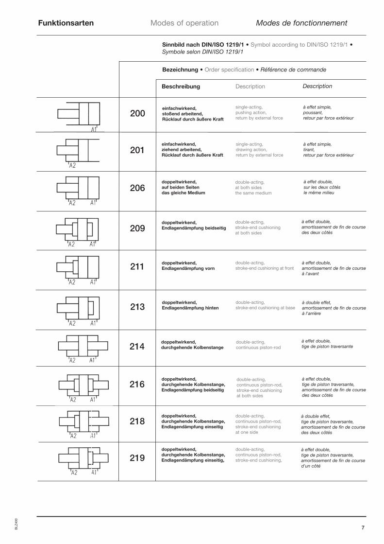
Funktionsarten Modes of operation Modes de fonctionnement
7
à double effet, amortissement de fin de course à l'arrière
à effet double,amortissement de fin de course à l'avant
à effet double, amortissement de fin de coursedes deux côtès
à effet double,sur les deux côtés le même milieu
à effet simple, tirant, retour par force extérieur
à effet simple,poussant, retour par force extérieur
Description
Sinnbild nach DIN/ISO 1219/1 • Symbol according to DIN/ISO 1219/1 • Symbole selon DIN/ISO 1219/1
Bezeichnung • Order specification • Référence de commande
Beschreibung Description
200
201
206
209
211
213
einfachwirkend, stoßend arbeitend, Rücklauf durch äußere Kraft
einfachwirkend, ziehend arbeitend,Rücklauf durch äußere Kraft
single-acting, drawing action,return by external force
single-acting, pushing action, return by external force
double-acting, at both sides the same medium
doppeltwirkend, auf beiden Seiten das gleiche Medium
doppeltwirkend, Endlagendämpfung beidseitig
double-acting,stroke-end cushioning at front
doppeltwirkend, Endlagendämpfung vorn
doppeltwirkend, Endlagendämpfung hinten
double-acting, stroke-end cushioning at base
à effet double,tige de piston traversante
doppeltwirkend, durchgehende Kolbenstange
double-acting, continuous piston-rod
à effet double,tige de piston traversante, amortissement de fin de course des deux côtés
doppeltwirkend, durchgehende Kolbenstange,Endlagendämpfung beidseitig
double-acting, continuous piston-rod, stroke-end cushioningat both sides
à double effet,tige de piston traversante, amortissement de fin de course des deux côtés
doppeltwirkend, durchgehende Kolbenstange,Endlagendämpfung einseitig
double-acting, continuous piston-rod, stroke-end cushioning at one side
double-acting, stroke-end cushioning at both sides
BLZ
400
214
216
218
à effet double,tige de piston traversante, amortissement de fin de coursed'un côté
doppeltwirkend, durchgehende Kolbenstange,Endlagendämpfung einseitig,
double-acting, continuous piston-rod, stroke-end cushioning,219
1.11.2
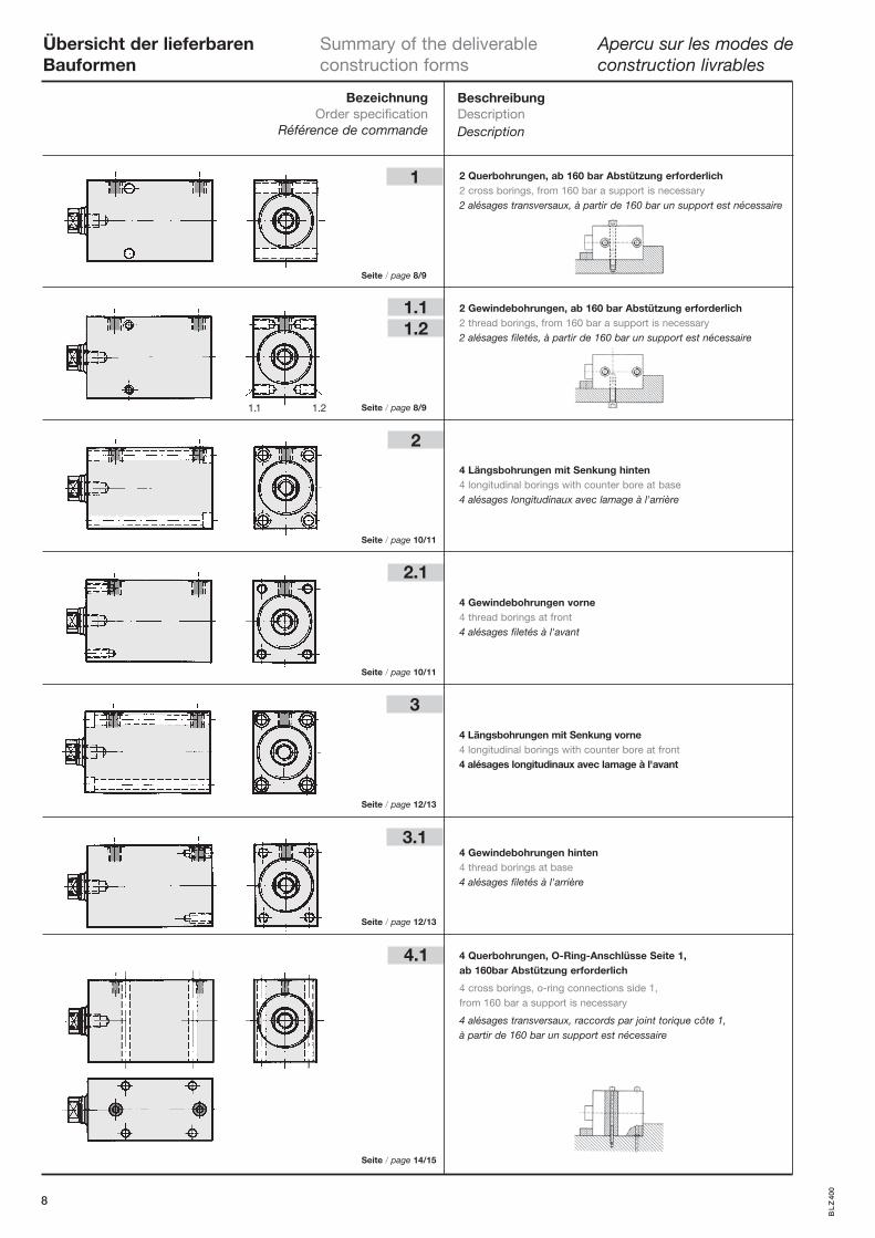
1
2
2.1
3
3.1
4.1
Übersicht der lieferbaren Summary of the deliverable Apercu sur les modes deBauformen construction forms construction livrables
8
2 Querbohrungen, ab 160 bar Abstützung erforderlich 2 cross borings, from 160 bar a support is necessary 2 alésages transversaux, à partir de 160 bar un support est nécessaire
2 Gewindebohrungen, ab 160 bar Abstützung erforderlich 2 thread borings, from 160 bar a support is necessary 2 alésages filetés, à partir de 160 bar un support est nécessaire
4 Längsbohrungen mit Senkung hinten 4 longitudinal borings with counter bore at base 4 alésages longitudinaux avec lamage à l'arrière 4 Gewindebohrungen vorne 4 thread borings at front 4 alésages filetés à l'avant 4 Längsbohrungen mit Senkung vorne 4 longitudinal borings with counter bore at front 4 alésages longitudinaux avec lamage à l'avant 4 Gewindebohrungen hinten 4 thread borings at base 4 alésages filetés à l'arrière
4 Querbohrungen, O-Ring-Anschlüsse Seite 1,
ab 160bar Abstützung erforderlich
4 cross borings, o-ring connections side 1, from 160 bar a support is necessary
4 alésages transversaux, raccords par joint torique côte 1, à partir de 160 bar un support est nécessaire
1.1 1.2
BL
Z40
0
Seite / page 8/9
Seite / page 8/9
Seite / page 10/11
Seite / page 10/11
Seite / page 12/13
Seite / page 12/13
Seite / page 14/15
BezeichnungOrder specification
Référence de commande
BeschreibungDescriptionDescription
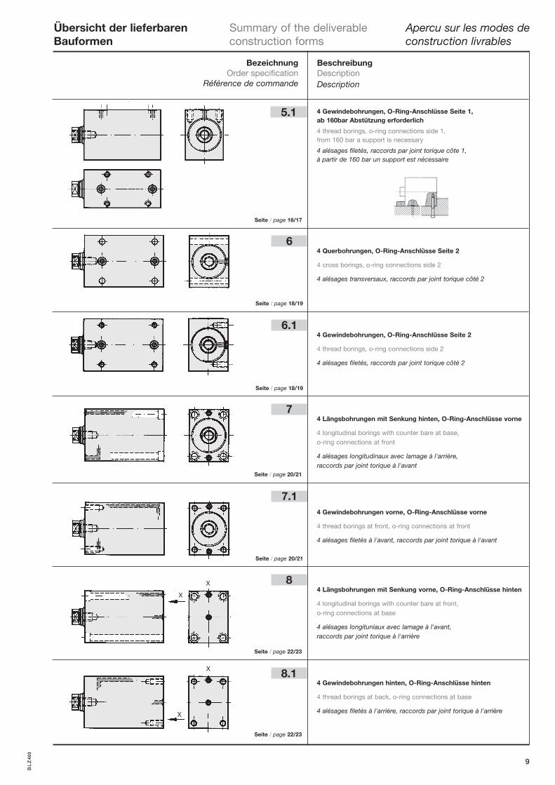
6
5.1
6.1
7
7.1
8
8.1
Übersicht der lieferbaren Summary of the deliverable Apercu sur les modes deBauformen construction forms construction livrables
9
4 Gewindebohrungen, O-Ring-Anschlüsse Seite 1, ab 160bar Abstützung erforderlich 4 thread borings, o-ring connections side 1, from 160 bar a support is necessary
4 alésages filetés, raccords par joint torique côte 1, à partir de 160 bar un support est nécessaire
4 Querbohrungen, O-Ring-Anschlüsse Seite 2
4 cross borings, o-ring connections side 2
4 alésages transversaux, raccords par joint torique côté 2
4 Gewindebohrungen, O-Ring-Anschlüsse Seite 2
4 thread borings, o-ring connections side 2
4 alésages filetés, raccords par joint torique côté 2
4 Längsbohrungen mit Senkung hinten, O-Ring-Anschlüsse vorne
4 longitudinal borings with counter bare at base, o-ring connections at front
4 alésages longitudinaux avec lamage à l'arrière, raccords par joint torique à l'avant
4 Gewindebohrungen vorne, O-Ring-Anschlüsse vorne
4 thread borings at front, o-ring connections at front
4 alésages filetés à l'avant, raccords par joint torique à l'avant
4 Längsbohrungen mit Senkung vorne, O-Ring-Anschlüsse hinten
4 longitudinal borings with counter bare at front, o-ring connections at base
4 alésages longituniaux avec lamage à l'avant, raccords par joint torique à l'arrière
4 Gewindebohrungen hinten, O-Ring-Anschlüsse hinten
4 thread borings at back, o-ring connections at base
4 alésages filetés à l'arrière, raccords par joint torique à l'arrière
X
X
X
X
BL
Z40
0
Seite / page 16/17
Seite / page 18/19
Seite / page 18/19
Seite / page 20/21
Seite / page 20/21
Seite / page 22/23
Seite / page 22/23
BezeichnungOrder specification
Référence de commande
BeschreibungDescriptionDescription
BLZ NI 400 DK
BLZ NI 400
BLZ 400
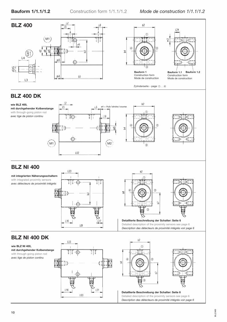
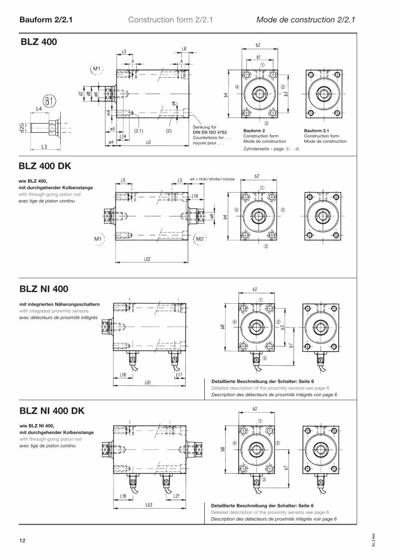
Bauform 1/1.1/1.2 Construction form 1/1.1/1.2 Mode de construction 1/1.1/1.2
10
BLZ 400 DK
a4 + Hub / stroke / course
Zylinderseite - page � . . .�
M1
M1 M2
BL
Z40
0
Detaillierte Beschreibung der Schalter: Seite 6Detailed description of the proximity sensors see page 6Description des détecteurs de proximité intégrés voir page 6
Detaillierte Beschreibung der Schalter: Seite 6Detailed description of the proximity sensors see page 6Description des détecteurs de proximité intégrés voir page 6
wie BLZ 400, mit durchgehender Kolbenstangewith through-going piston rodavec tige de piston continu
wie BLZ NI 400, mit durchgehender Kolbenstangewith through-going piston rodavec tige de piston continu
mit integrierten Näherungsschalternwith integrated proximity sensorsavec détecteurs de proximité intégrés
L4
L3
d2G
Bauform 1Construction formMode de construction
Bauform 1.1Construction formMode de construction
Bauform 1.2
➀
➁
➂
➃
➀
➁
➂
➃
➀
➁
➂
➃
➀
➁
➂
➃
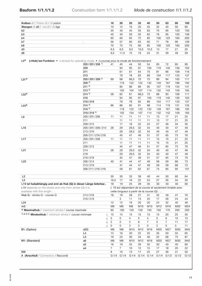
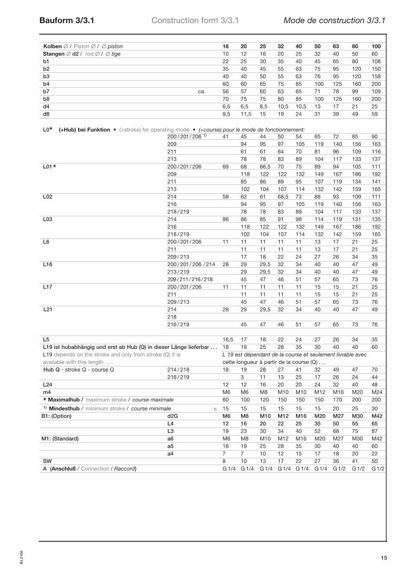
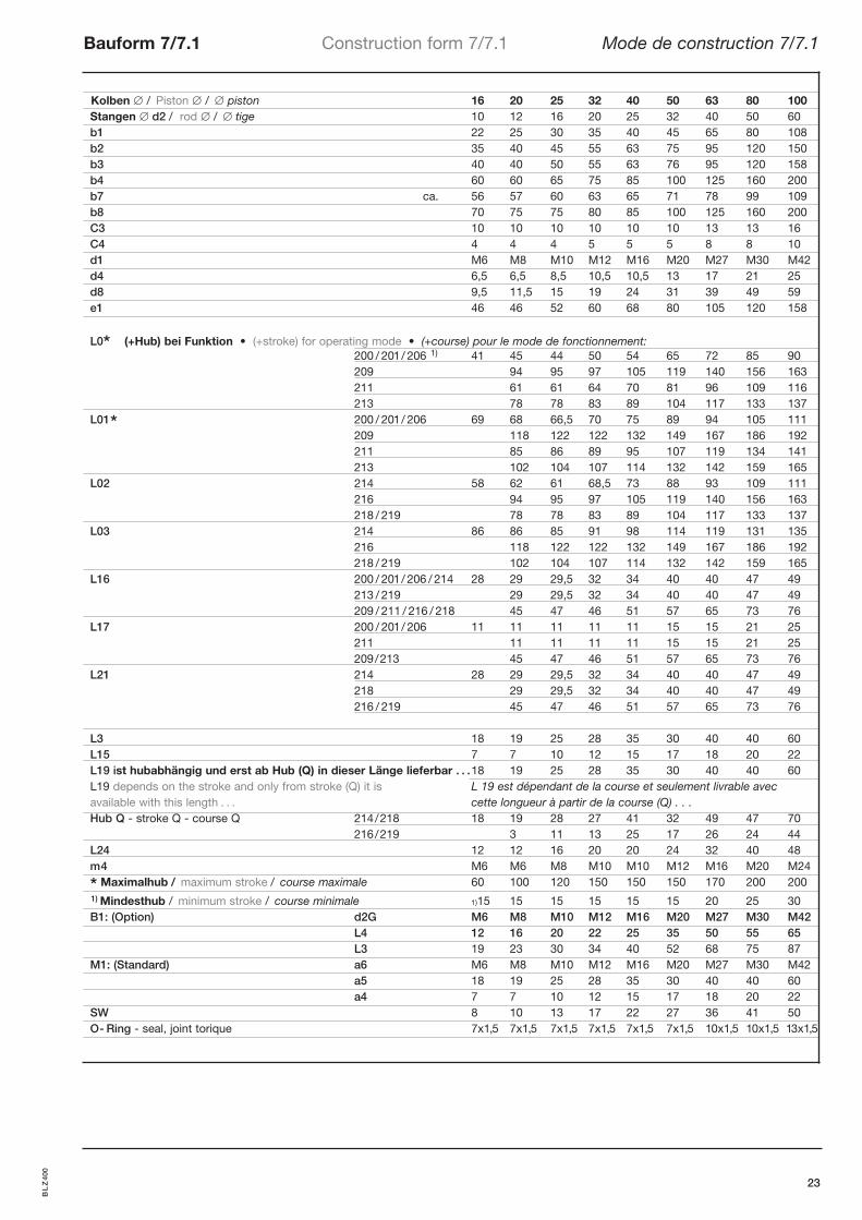
Kolben / Piston / piston 16 20 25 32 40 50 63 80 100Stangen d2 / rod / tige 10 12 16 20 25 32 40 50 60b2 35 40 45 55 63 75 95 120 150b3 40 40 50 55 63 76 95 120 158b4 60 60 65 75 85 100 125 160 200b7 . 56 57 60 63 65 71 78 99 109b8 70 75 75 80 85 100 125 160 200d3 6,5 6,5 8,5 10,5 10,5 13 17 21 25d8 9,5 11,5 15 19 24 31 39 49 59
L0* (+Hub) bei Funktion • (+stroke) for operating mode • (+course) pour le mode de fonctionnement: 200 / 201/ 206 1) 41 45 44 50 54 65 72 85 90 209 94 95 97 105 119 140 156 163 211 61 61 64 70 81 96 109 116 213 78 78 83 89 104 117 133 137
L01* 200 / 201/ 206 2) 69 68 66,5 70 75 89 94 105 111 209 2) 118 122 122 132 149 167 186 192 211 2) 85 86 89 95 107 119 134 141 213 2) 102 104 107 114 132 142 159 165
L02* 214 3) 58 62 61 68,5 73 88 93 109 111 216 94 95 97 105 119 140 156 163 218 / 219 78 78 83 89 104 117 133 137
L03* 214 4) 86 86 85 91 98 114 119 131 135 216 4) 118 122 122 132 149 167 186 192 218 / 219 4) 102 104 107 114 132 142 159 165
L6 200 / 201/ 206 11 11 11 11 11 13 17 21 25 211 11 11 11 11 13 17 21 25 209 / 213 17 18 22 24 27 26 34 35
L16 200 / 201/ 206 / 214 28 29 29,5 32 34 40 40 47 49 213 / 219 29 29,5 32 34 40 40 47 49 209 /211 /216 /218 45 47 46 51 57 65 73 76
L17 200 / 201/ 206 11 11 11 11 11 15 15 21 25 211 11 11 11 11 15 15 21 25 209 / 213 45 47 46 51 57 65 73 76
L21 214 28 29 29,5 32 34 40 40 47 49 218 29 29,5 32 34 40 40 47 49 216 / 219 45 47 46 51 57 65 73 76
L23 206 / 214 40 41 44 47 49 58 59 68 73 213 / 219 41 44 47 49 58 59 68 73 209 /211 /216 /218 59 61 62 67 74 85 95 101
L2 30 30 33 38 40 44 50 60 64L5 16,5 17 18 22 24 27 26 34 35L19 ist hubabhängig und erst ab Hub (Q) in dieser Länge lieferbar.. 18 19 25 28 35 30 40 40 60L19 depends on the stroke and only from stroke (Q) it is L 19 est dépendant de la course et seulement livrable avecavailable with this length . . . cette longueur à partir de la course (Q) . . .Hub Q - stroke Q - course Q 214 / 218 18 19 28 27 41 32 49 47 70
216 / 219 3 11 13 25 17 26 24 44L24 12 12 16 20 20 24 32 40 48m3 M6 M6 M8 M10 M10 M12 M16 M20 M24
* Maximalhub / maximum stroke / course maximale 60 100 120 150 150 150 170 200 2001) 2) 3) 4) Mindesthub / minimum stroke / course minimale 1) 15 15 15 15 15 15 20 25 30
2) 0 0 4 5 4 0 6 10 15 3) 2 0 5 8 7 0 7 11 17 4) 0 0 3 3 0 2 0 5 11
B1: (Option) d2G M6 M8 M10 M12 M16 M20 M27 M30 M42 L4 12 16 20 22 25 35 50 55 65 L3 19 23 30 34 40 52 68 75 87
M1: (Standard) a6 M6 M8 M10 M12 M16 M20 M27 M30 M42 a5 18 19 25 28 35 30 40 40 60 a4 7 7 10 12 15 17 18 20 22
SW 8 10 13 17 22 27 36 41 50A (Anschluß / Connection / Raccord) G 1/4 G 1/4 G1/4 G 1/4 G 1/4 G1/4 G1/2 G1/2 G1/2
Bauform 1/1.1/1.2 Construction form 1/1.1/1.2 Mode de construction 1/1.1/1.2
11
BL
Z40
0
BLZ 400
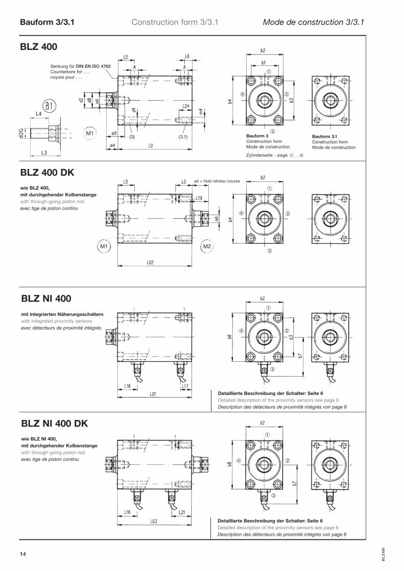
Bauform 2/2.1 Construction form 2/2.1 Mode de construction 2/2.1
12
(2.1) (2)Senkung für DIN EN ISO 4762Counterbore for . . .noyure pour . . .
Bauform 2Construction formMode de construction
Bauform 2.1Construction formMode de construction
Zylinderseite - page � . . .�
M1
M1 M2
BL
Z40
0
BLZ NI 400 DK
BLZ NI 400
BLZ 400 DK
Detaillierte Beschreibung der Schalter: Seite 6Detailed description of the proximity sensors see page 6Description des détecteurs de proximité intégrés voir page 6
Detaillierte Beschreibung der Schalter: Seite 6Detailed description of the proximity sensors see page 6Description des détecteurs de proximité intégrés voir page 6
wie BLZ 400, mit durchgehender Kolbenstangewith through-going piston rodavec tige de piston continu
wie BLZ NI 400, mit durchgehender Kolbenstangewith through-going piston rodavec tige de piston continu
mit integrierten Näherungsschalternwith integrated proximity sensorsavec détecteurs de proximité intégrés
L4
L3
d2G
a4 + Hub / stroke / course
➀
➁
➂
➃
➀
➁
➂
➃
➀
➁
➂
➃
➀
➁
➂
➃
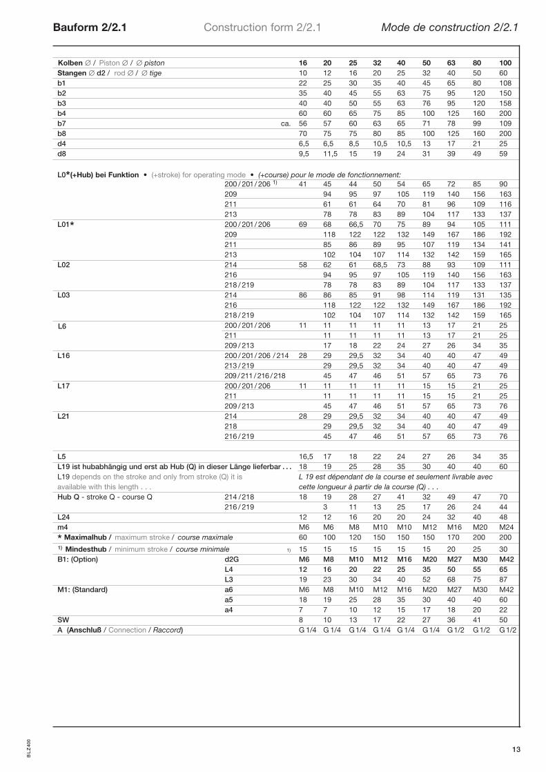
Kolben / Piston / piston 16 20 25 32 40 50 63 80 100Stangen d2 / rod / tige 10 12 16 20 25 32 40 50 60b1 22 25 30 35 40 45 65 80 108b2 35 40 45 55 63 75 95 120 150b3 40 40 50 55 63 76 95 120 158b4 60 60 65 75 85 100 125 160 200b7 ca. 56 57 60 63 65 71 78 99 109b8 70 75 75 80 85 100 125 160 200d4 6,5 6,5 8,5 10,5 10,5 13 17 21 25d8 9,5 11,5 15 19 24 31 39 49 59
L0*(+Hub) bei Funktion • (+stroke) for operating mode • (+course) pour le mode de fonctionnement: 200 / 201/ 206 1) 41 45 44 50 54 65 72 85 90 209 94 95 97 105 119 140 156 163 211 61 61 64 70 81 96 109 116 213 78 78 83 89 104 117 133 137
L01* 200 / 201/ 206 69 68 66,5 70 75 89 94 105 111 209 118 122 122 132 149 167 186 192 211 85 86 89 95 107 119 134 141 213 102 104 107 114 132 142 159 165
L02 214 58 62 61 68,5 73 88 93 109 111 216 94 95 97 105 119 140 156 163
218 / 219 78 78 83 89 104 117 133 137L03 214 86 86 85 91 98 114 119 131 135 216 118 122 122 132 149 167 186 192
218 / 219 102 104 107 114 132 142 159 165
L6 200 / 201/ 206 11 11 11 11 11 13 17 21 25 211 11 11 11 11 13 17 21 25 209 / 213 17 18 22 24 27 26 34 35
L16 200 / 201/ 206 / 214 28 29 29,5 32 34 40 40 47 49 213 / 219 29 29,5 32 34 40 40 47 49
209 /211 /216 /218 45 47 46 51 57 65 73 76L17 200 / 201/ 206 11 11 11 11 11 15 15 21 25 211 11 11 11 11 15 15 21 25
209 / 213 45 47 46 51 57 65 73 76L21 214 28 29 29,5 32 34 40 40 47 49
218 29 29,5 32 34 40 40 47 49 216 / 219 45 47 46 51 57 65 73 76
L5 16,5 17 18 22 24 27 26 34 35L19 ist hubabhängig und erst ab Hub (Q) in dieser Länge lieferbar . . . 18 19 25 28 35 30 40 40 60L19 depends on the stroke and only from stroke (Q) it is L 19 est dépendant de la course et seulement livrable avecavailable with this length . . . cette longueur à partir de la course (Q) . . .Hub Q - stroke Q - course Q 214 /218 18 19 28 27 41 32 49 47 70
216 / 219 3 11 13 25 17 26 24 44L24 12 12 16 20 20 24 32 40 48m4 M6 M6 M8 M10 M10 M12 M16 M20 M24
* Maximalhub / maximum stroke / course maximale 60 100 120 150 150 150 170 200 2001) Mindesthub / minimum stroke / course minimale 1) 15 15 15 15 15 15 20 25 30B1: (Option) d2G M6 M8 M10 M12 M16 M20 M27 M30 M42 L4 12 16 20 22 25 35 50 55 65 L3 19 23 30 34 40 52 68 75 87M1: (Standard) a6 M6 M8 M10 M12 M16 M20 M27 M30 M42 a5 18 19 25 28 35 30 40 40 60
a4 7 7 10 12 15 17 18 20 22SW 8 10 13 17 22 27 36 41 50A (Anschluß / Connection / Raccord) G 1/4 G 1/4 G1/4 G 1/4 G 1/4 G1/4 G1/2 G1/2 G1/2
Bauform 2/2.1 Construction form 2/2.1 Mode de construction 2/2.1
13
BL
Z40
0
BLZ 400
Bauform 3/3.1 Construction form 3/3.1 Mode de construction 3/3.1
14
(3) (3.1) Bauform 3Construction formMode de construction
Bauform 3.1Construction formMode de construction
Zylinderseite - page � . . .�
M1
M1 M2
Senkung für DIN EN ISO 4762Counterbore for . . .noyure pour . . .
BL
Z40
0
BLZ NI 400 DK
BLZ NI 400
BLZ 400 DK
Detaillierte Beschreibung der Schalter: Seite 6Detailed description of the proximity sensors see page 6Description des détecteurs de proximité intégrés voir page 6
Detaillierte Beschreibung der Schalter: Seite 6Detailed description of the proximity sensors see page 6Description des détecteurs de proximité intégrés voir page 6
wie BLZ 400, mit durchgehender Kolbenstangewith through-going piston rodavec tige de piston continu
wie BLZ NI 400, mit durchgehender Kolbenstangewith through-going piston rodavec tige de piston continu
mit integrierten Näherungsschalternwith integrated proximity sensorsavec détecteurs de proximité intégrés
L4
L3
d2G
a4 + Hub / stroke / course
➀
➁
➂
➃
➀
➁
➂
➃
➀
➁
➂
➃
➀
➁
➂
➃
Bauform 3/3.1 Construction form 3/3.1 Mode de construction 3/3.1
15
Kolben / Piston / piston 16 20 25 32 40 50 63 80 100Stangen d2 / rod / tige 10 12 16 20 25 32 40 50 60b1 22 25 30 35 40 45 65 80 108b2 35 40 45 55 63 75 95 120 150b3 40 40 50 55 63 76 95 120 158b4 60 60 65 75 85 100 125 160 200b7 ca. 56 57 60 63 65 71 78 99 109b8 70 75 75 80 85 100 125 160 200d4 6,5 6,5 8,5 10,5 10,5 13 17 21 25d8 9,5 11,5 15 19 24 31 39 49 59
L0* (+Hub) bei Funktion • (+stroke) for operating mode • (+course) pour le mode de fonctionnement: 200 / 201/ 206 1) 41 45 44 50 54 65 72 85 90 209 94 95 97 105 119 140 156 163 211 61 61 64 70 81 96 109 116 213 78 78 83 89 104 117 133 137
L01* 200 / 201/ 206 69 68 66,5 70 75 89 94 105 111 209 118 122 122 132 149 167 186 192
211 85 86 89 95 107 119 134 141 213 102 104 107 114 132 142 159 165
L02 214 58 62 61 68,5 73 88 93 109 111 216 94 95 97 105 119 140 156 163
218 / 219 78 78 83 89 104 117 133 137L03 214 86 86 85 91 98 114 119 131 135 216 118 122 122 132 149 167 186 192
218 / 219 102 104 107 114 132 142 159 165L6 200 / 201/ 206 11 11 11 11 11 13 17 21 25 211 11 11 11 11 13 17 21 25 209 / 213 17 18 22 24 27 26 34 35L16 200 / 201/ 206 / 214 28 29 29,5 32 34 40 40 47 49 213 / 219 29 29,5 32 34 40 40 47 49
209 /211 /216 /218 45 47 46 51 57 65 73 76L17 200 / 201/ 206 11 11 11 11 11 15 15 21 25 211 11 11 11 11 15 15 21 25
209 / 213 45 47 46 51 57 65 73 76L21 214 28 29 29,5 32 34 40 40 47 49
218 216 / 219 45 47 46 51 57 65 73 76
L5 16,5 17 18 22 24 27 26 34 35L19 ist hubabhängig und erst ab Hub (Q) in dieser Länge lieferbar . . . 18 19 25 28 35 30 40 40 60L19 depends on the stroke and only from stroke (Q) it is L 19 est dépendant de la course et seulement livrable avecavailable with this length . . . cette longueur à partir de la course (Q) . . .Hub Q - stroke Q - course Q 214 / 218 18 19 28 27 41 32 49 47 70
216 / 219 3 11 13 25 17 26 24 44L24 12 12 16 20 20 24 32 40 48m4 M6 M6 M8 M10 M10 M12 M16 M20 M24
* Maximalhub / maximum stroke / course maximale 60 100 120 150 150 150 170 200 2001) Mindesthub / minimum stroke / course minimale 1) 15 15 15 15 15 15 20 25 30
B1: (Option) d2G M6 M8 M10 M12 M16 M20 M27 M30 M42 L4 12 16 20 22 25 35 50 55 65 L3 19 23 30 34 40 52 68 75 87
M1: (Standard) a6 M6 M8 M10 M12 M16 M20 M27 M30 M42 a5 18 19 25 28 35 30 40 40 60
a4 7 7 10 12 15 17 18 20 22SW 8 10 13 17 22 27 36 41 50A (Anschluß / Connection / Raccord) G 1/4 G 1/4 G1/4 G 1/4 G 1/4 G1/4 G1/2 G1/2 G1/2
BL
Z40
0
Detaillierte Beschreibung der Schalter: Seite 6Detailed description of the proximity sensors see page 6Description des détecteurs de proximité intégrés voir page 6
BLZ 400
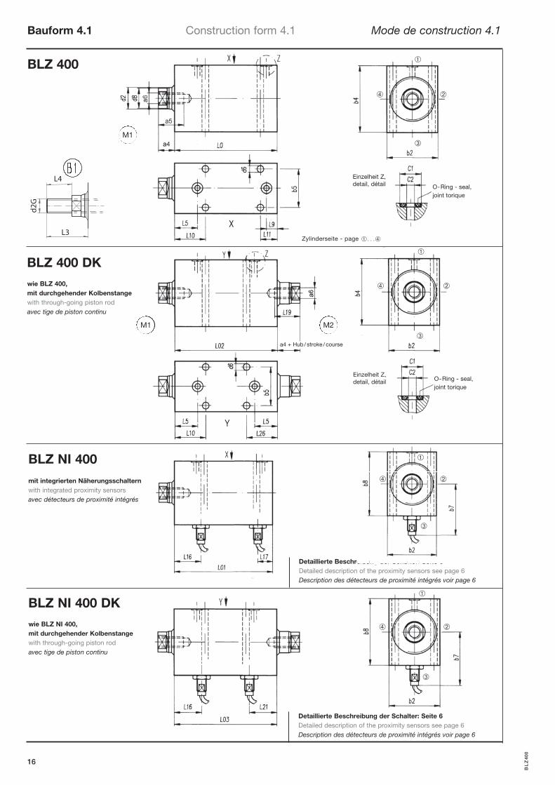
Bauform 4.1 Construction form 4.1 Mode de construction 4.1
16
D
D
D
D
e
e
i
i
b
b
u
u
n
n
g
g
d
d
e
e
r
r
S
S
c
c
h
h
a
a
l
l
t
t
e
e
r
r
:
:
S
S
e
e
i
i
t
t
e
e
6
6
X
Y
O-Ring - seal,joint torique
O-Ring - seal,joint torique
Einzelheit Z, detail, détail
Einzelheit Z, detail, détail
Zylinderseite - page � . . .�
M1
M1 M2
BL
Z40
0
BLZ NI 400 DK
BLZ NI 400
BLZ 400 DK
Detaillierte Beschreibung der Schalter: Seite 6Detailed description of the proximity sensors see page 6Description des détecteurs de proximité intégrés voir page 6
wie BLZ 400, mit durchgehender Kolbenstangewith through-going piston rodavec tige de piston continu
wie BLZ NI 400, mit durchgehender Kolbenstangewith through-going piston rodavec tige de piston continu
mit integrierten Näherungsschalternwith integrated proximity sensorsavec détecteurs de proximité intégrés
L4
L3
d2G
a4 + Hub / stroke / course
➀
➁
➂
➃
➀
➁
➂
➃
➀
➁
➂
➃
➀
➁
➂
➃
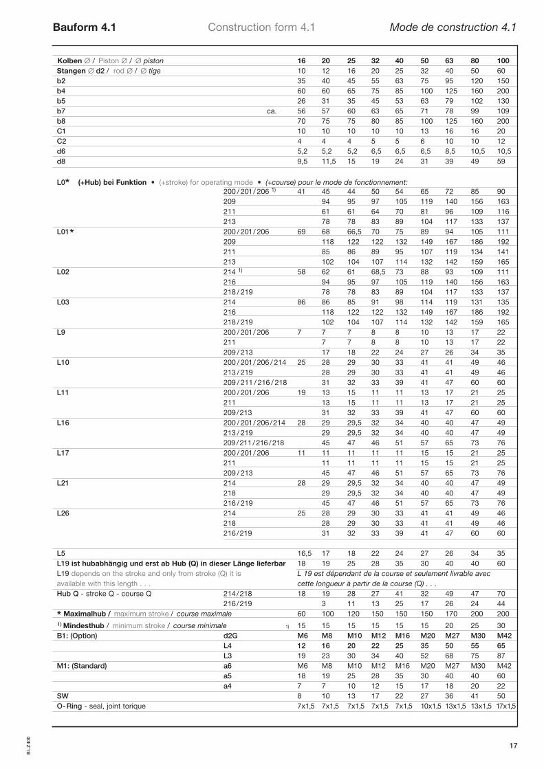
Kolben / Piston / piston 16 20 25 32 40 50 63 80 100Stangen d2 / rod / tige 10 12 16 20 25 32 40 50 60b2 35 40 45 55 63 75 95 120 150b4 60 60 65 75 85 100 125 160 200b5 26 31 35 45 53 63 79 102 130b7 ca. 56 57 60 63 65 71 78 99 109b8 70 75 75 80 85 100 125 160 200C1 10 10 10 10 10 13 16 16 20C2 4 4 4 5 5 6 10 10 12d6 5,2 5,2 5,2 6,5 6,5 6,5 8,5 10,5 10,5d8 9,5 11,5 15 19 24 31 39 49 59
L0* (+Hub) bei Funktion • (+stroke) for operating mode • (+course) pour le mode de fonctionnement: 200 / 201/ 206 1) 41 45 44 50 54 65 72 85 90 209 94 95 97 105 119 140 156 163 211 61 61 64 70 81 96 109 116 213 78 78 83 89 104 117 133 137
L01* 200 / 201/ 206 69 68 66,5 70 75 89 94 105 111 209 118 122 122 132 149 167 186 192
211 85 86 89 95 107 119 134 141 213 102 104 107 114 132 142 159 165
L02 214 1) 58 62 61 68,5 73 88 93 109 111 216 94 95 97 105 119 140 156 163
218 / 219 78 78 83 89 104 117 133 137L03 214 86 86 85 91 98 114 119 131 135 216 118 122 122 132 149 167 186 192 218 / 219 102 104 107 114 132 142 159 165
L9 200 / 201/ 206 7 7 7 8 8 10 13 17 22 211 7 7 8 8 10 13 17 22 209 / 213 17 18 22 24 27 26 34 35
L10 200 / 201/ 206 / 214 25 28 29 30 33 41 41 49 46 213 / 219 28 29 30 33 41 41 49 46
209 / 211 / 216 / 218 31 32 33 39 41 47 60 60L11 200 / 201/ 206 19 13 15 11 11 13 17 21 25 211 13 15 11 11 13 17 21 25
209/213 31 32 33 39 41 47 60 60L16 200 / 201/ 206/214 28 29 29,5 32 34 40 40 47 49 213 / 219 29 29,5 32 34 40 40 47 49
209 /211 /216 /218 45 47 46 51 57 65 73 76L17 200 / 201/ 206 11 11 11 11 11 15 15 21 25 211 11 11 11 11 15 15 21 25
209 / 213 45 47 46 51 57 65 73 76L21 214 28 29 29,5 32 34 40 40 47 49
218 29 29,5 32 34 40 40 47 49 216 / 219 45 47 46 51 57 65 73 76
L26 214 25 28 29 30 33 41 41 49 46 218 28 29 30 33 41 41 49 46 216/219 31 32 33 39 41 47 60 60
L5 16,5 17 18 22 24 27 26 34 35L19 ist hubabhängig und erst ab Hub (Q) in dieser Länge lieferbar 18 19 25 28 35 30 40 40 60L19 depends on the stroke and only from stroke (Q) it is L 19 est dépendant de la course et seulement livrable avecavailable with this length . . . cette longueur à partir de la course (Q) . . .Hub Q - stroke Q - course Q 214/218 18 19 28 27 41 32 49 47 70
216/219 3 11 13 25 17 26 24 44
* Maximalhub / maximum stroke / course maximale 60 100 120 150 150 150 170 200 2001) Mindesthub / minimum stroke / course minimale 1) 15 15 15 15 15 15 20 25 30B1: (Option) d2G M6 M8 M10 M12 M16 M20 M27 M30 M42 L4 12 16 20 22 25 35 50 55 65 L3 19 23 30 34 40 52 68 75 87M1: (Standard) a6 M6 M8 M10 M12 M16 M20 M27 M30 M42 a5 18 19 25 28 35 30 40 40 60
a4 7 7 10 12 15 17 18 20 22SW 8 10 13 17 22 27 36 41 50O-Ring - seal, joint torique 7x1,5 7x1,5 7x1,5 7x1,5 7x1,5 10x1,5 13x1,5 13x1,5 17x1,5
Bauform 4.1 Construction form 4.1 Mode de construction 4.1
17
BL
Z40
0
BLZ 400
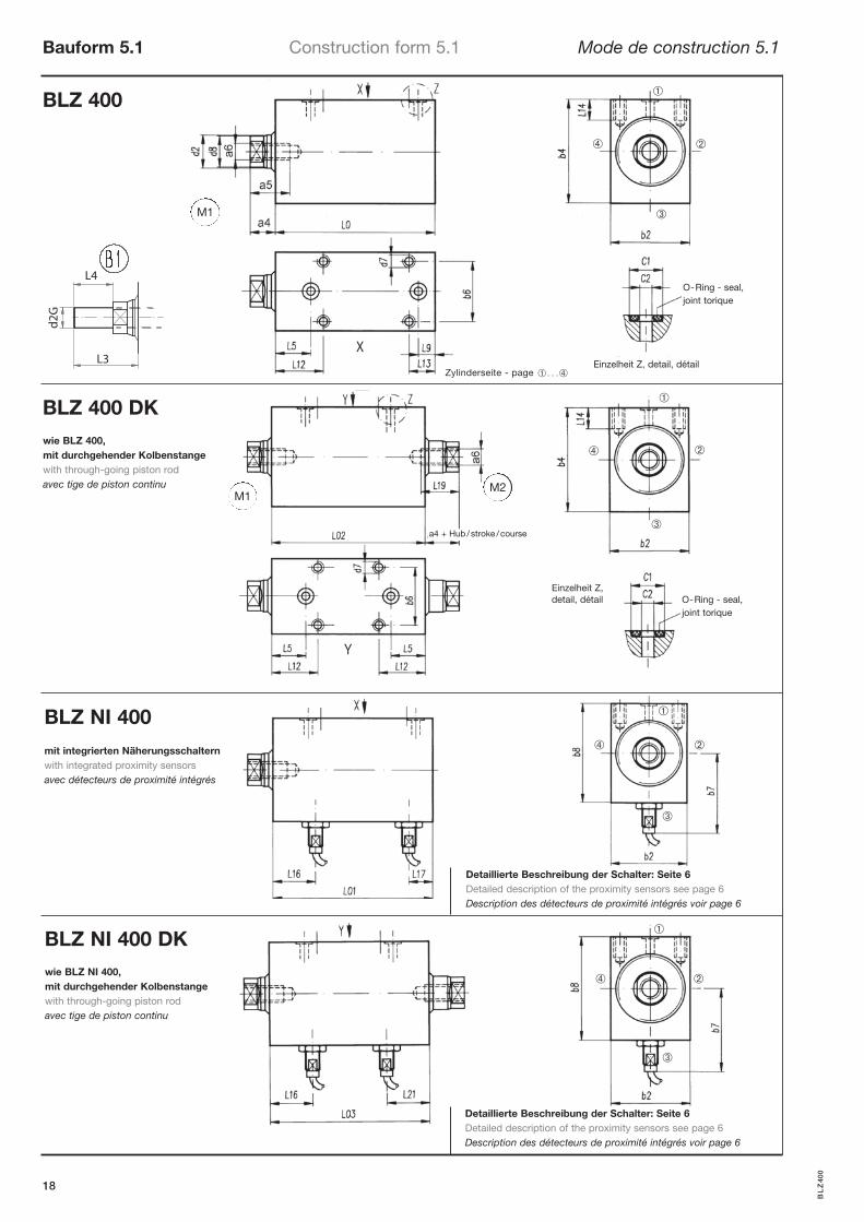
Bauform 5.1 Construction form 5.1 Mode de construction 5.1
18
X
Y
O-Ring - seal,joint torique
O-Ring - seal,joint torique
Einzelheit Z, detail, détail
Einzelheit Z, detail, détail
Zylinderseite - page � . . .�
M1
M1M2
BL
Z40
0
BLZ NI 400 DK
BLZ NI 400
BLZ 400 DK
Detaillierte Beschreibung der Schalter: Seite 6Detailed description of the proximity sensors see page 6Description des détecteurs de proximité intégrés voir page 6
Detaillierte Beschreibung der Schalter: Seite 6Detailed description of the proximity sensors see page 6Description des détecteurs de proximité intégrés voir page 6
wie BLZ 400, mit durchgehender Kolbenstangewith through-going piston rodavec tige de piston continu
wie BLZ NI 400, mit durchgehender Kolbenstangewith through-going piston rodavec tige de piston continu
mit integrierten Näherungsschalternwith integrated proximity sensorsavec détecteurs de proximité intégrés
L4
L3
d2G
a4 + Hub / stroke / course
➀
➁
➂
➃
➀
➁
➂
➃
➀
➁
➂
➃
➀
➁
➂
➃
Bauform 5.1 Construction form 5.1 Mode de construction 5.1
19
Kolben / Piston / piston 16 20 25 32 40 50 63 80 100Stangen d2 / rod / tige 10 12 16 20 25 32 40 50 60b2 35 40 45 55 63 75 95 120 150b4 60 60 65 75 85 100 125 160 200b6 20 26 31 41 49 59 75 100 130b7 ca. 56 57 60 63 65 71 78 99 109b8 70 75 75 80 85 100 125 160 200C1 10 10 10 10 10 13 16 16 20C2 4 4 4 5 5 6 10 10 12d1 M6 M8 M10 M12 M16 M20 M27 M30 M42d7 M8 M8 M8 M8 M8 M8 M12 M12 M12d8 9,5 11,5 15 19 24 31 39 49 59
L0* (+Hub) bei Funktion • (+stroke) for operating mode • (+course) pour le mode de fonctionnement: 200 / 201/ 206 1) 41 45 44 50 54 65 72 85 90 209 94 95 97 105 119 140 156 163 211 61 61 64 70 81 96 109 116 213 78 78 83 89 104 117 133 137
L01* 200 / 201/ 206 69 68 66,5 70 75 89 94 105 111 209 118 122 122 132 149 167 186 192
211 85 86 89 95 107 119 134 141 213 102 104 107 114 132 142 159 165
L02 214 2) 58 62 61 68,5 73 88 93 109 111 216 94 95 97 105 119 140 156 163
218 / 219 78 78 83 89 104 117 133 137L03 214 86 86 85 91 98 114 119 131 135 216 118 122 122 132 149 167 186 192
218 / 219 102 104 107 114 132 142 159 165L9 200 / 201/ 206 7 7 7 8 8 10 13 17 22
211 7 7 8 8 10 13 17 22 209 / 213 17 18 22 24 27 26 34 35
L13 200 / 201/ 206 23 20 13 11 11 13 17 21 25 211 20 13 11 11 13 17 21 25
209 / 213 29 20 22 24 27 26 34 35L16 200 / 201/ 206/214 28 29 29,5 32 34 40 40 47 49 213 / 219 29 29,5 32 34 40 40 47 49
209 /211 /216 /218 45 47 46 51 57 65 73 76L17 200 / 201/ 206 11 11 11 11 11 15 15 21 25 211 11 11 11 11 15 15 21 25
209 / 213 45 47 46 51 57 65 73 76L21 214 28 29 29,5 32 34 40 40 47 49
218 29 29,5 32 34 40 40 47 49 216 / 219 45 47 46 51 57 65 73 76
L3 18 19 25 28 35 30 40 40 60L5 16,5 17 18 22 24 27 26 34 35L12 28,5 29 20 22 24 27 26 34 35L14 16 15 16 16 18 18 22 22 22L15 7 7 10 12 15 17 18 20 22L19 ist hubabhängig und erst ab Hub (Q) in dieser Länge lieferbar 18 19 25 28 35 30 40 40 60L19 depends on the stroke and only from stroke (Q) it is L 19 est dépendant de la course et seulement livrable avecavailable with this length . . . cette longueur à partir de la course (Q) . . .Hub Q - stroke Q - course Q 214/218 18 19 28 27 41 32 49 47 70
216/219 3 11 13 25 17 26 24 44
* Maximalhub / maximum stroke / course maximale 60 100 120 150 150 150 170 200 2001) 2) Mindesthub / minimum stroke / course minimale 1) 35 30 20 15 15 15 20 25 30
2) 25 20 10 0 0 0 0 0 0B1: (Option) d2G M6 M8 M10 M12 M16 M20 M27 M30 M42 L4 12 16 20 22 25 35 50 55 65 L3 19 23 30 34 40 52 68 75 87M1: (Standard) a6 M6 M8 M10 M12 M16 M20 M27 M30 M42 a5 18 19 25 28 35 30 40 40 60
a4 7 7 10 12 15 17 18 20 22SW 8 10 13 17 22 27 36 41 50O-Ring - seal, joint torique 7x1,5 7x1,5 7x1,5 7x1,5 7x1,5 10x1,5 13x1,5 13x1,5 17x1,5
BL
Z40
0
• spiegelbildlich zu Bauform 6 -> 6.4 (mit Nut Zusatz: N4)mirror image to construction form 6 -> 6.4 (with groove: N4)renversé du mode de construction 6 -> 6.4 (avec rainure: N4)
• spiegelbildlich zu Bauform 6.1 -> 6.14 (mit Nut Zusatz: N4)mirror image to construction form 6 -> 6.14 (with groove: N4)renversé du mode de construction 6 -> 6.14 (avec rainure: N4)
Bestellbeispiel / Example of order / Exemple de commande:
BLZ400-6.4-32/20/15-206/M1/N4BLZNI400-6.4-32/20/15-206/M1/N4
BLZ 400
Bauform 6/6.1 Construction form 6/6.1 Mode de construction 6/6.1
20
Bauform 6Construction form
Mode de construction
Bauform 6.1Construction formMode de construction
Einzelheit Z, detail, détail
O-Ring - seal,joint torique
Einzelheit Z, detail, détail
O-Ring - seal, joint torique
Zylinderseite - page � . . .�
M1
M1 M2
BL
Z40
0
BLZ NI 400 DK
BLZ NI 400
BLZ 400 DK
Detaillierte Beschreibung der Schalter: Seite 6Detailed description of the proximity sensors see page 6Description des détecteurs de proximité intégrés voir page 6
Detaillierte Beschreibung der Schalter: Seite 6Detailed description of the proximity sensors see page 6Description des détecteurs de proximité intégrés voir page 6
wie BLZ 400, mit durchgehender Kolbenstangewith through-going piston rodavec tige de piston continu
wie BLZ NI 400, mit durchgehender Kolbenstangewith through-going piston rodavec tige de piston continu
mit integrierten Näherungsschalternwith integrated proximity sensorsavec détecteurs de proximité intégrés
Bauform 6.4Construction form
Mode de construction
Bauform 6.14Construction formMode de construction
spiegelbildliche Bauform s.o.mirror image to construction form see aboverenversé du mode de construction c.f.
L4
L3
d2G
a4 + Hub / stroke / course
➀
➁
➂
➃
➀
➁
➂
➃
➀
➁
➂
➃
➀
➁
➂
➃
➀
➁
➂
➃
Bauform 6/6.1 Construction form 6/6.1 Mode de construction 6/6.1
21
Kolben / Piston / piston 16 20 25 32 40 50 63 80 100Stangen d2 / rod / tige 10 12 16 20 25 32 40 50 60b2 35 40 45 55 63 75 95 120 150b3 40 40 50 55 63 76 95 120 158b4 60 60 65 75 85 100 125 160 200b7 ca. 56 57 60 63 65 71 78 99 109b8 70 75 75 80 85 100 125 160 200C1 10 10 10 10 10 13 16 16 20C2 4 4 4 5 5 6 10 10 12d1 M6 M8 M10 M12 M16 M20 M27 M30 M42d8 9,5 11,5 15 19 24 31 39 49 59d9 6,5 6,5 6,5 8,5 8,5 8,5 10,5 13 13
L0* (+Hub) bei Funktion • (+stroke) for operating mode • (+course) pour le mode de fonctionnement: 200 / 201/ 206 1) 41 45 44 50 54 65 72 85 90 209 94 95 97 105 119 140 156 163 211 61 61 64 70 81 96 109 116 213 78 78 83 89 104 117 133 137
L01* 200 / 201/ 206 2) 69 68 66,5 70 75 89 94 105 111 209 118 122 122 132 149 167 186 192
211 85 86 89 95 107 119 134 141 213 102 104 107 114 132 142 159 165
L02 214 58 62 61 68,5 73 88 93 109 111 216 94 95 97 105 119 140 156 163
218 / 219 78 78 83 89 104 117 133 137L03 214 86 86 85 91 98 114 119 131 135 216 118 122 122 132 149 167 186 192
218 / 219 102 104 107 114 132 142 159 165L9 / L29 200 / 201/ 206 7 7 7 8 8 10 13 17 22
211 7 7 8 8 10 13 17 22 209 / 213 17 18 22 24 27 26 34 35
L16 200 / 201/ 206 / 214 28 29 29,5 32 34 40 40 47 49 213 / 219 29 29,5 32 34 40 40 47 49
209 / 211 / 216 / 218 45 47 46 51 57 65 73 76L17 200 / 201/ 206 11 11 11 11 11 15 15 21 25 211 11 11 11 11 15 15 21 25
209/213 45 47 46 51 57 65 73 76L21 214 28 29 29,5 32 34 40 40 47 49
218 29 29,5 32 34 40 40 47 49 216 / 219 45 47 46 51 57 65 73 76
L3 18 19 25 28 35 30 40 40 60L5 / L28 16,5 17 18 22 24 27 26 34 35L15 7 7 10 12 15 17 18 20 22
L19 ist hubabhängig und erst ab Hub (Q) in dieser Länge lieferbar . . . 18 19 25 28 35 30 40 40 60L19 depends on the stroke and only from stroke (Q) it is L 19 est dépendant de la course et seulement livrable avecavailable with this length . . . cette longueur à partir de la course (Q) . . .
Hub Q - stroke Q - course Q 214 / 218 18 19 28 27 41 32 49 47 70 216/219 3 11 13 25 17 26 24 44
L22 200 / 201/ 206 25 26 26 27 28 32 33 41 45 211 26 26 27 28 32 33 41 45
209 / 213 17 18 22 24 27 26 34 35L25 16,5 17 18 18 20 27 26 34 35L27 12 12 12 16 16 16 20 24 24m9 M6 M6 M6 M8 M8 M8 M10 M12 M12
* Maximalhub / maximum stroke / course maximale 60 100 120 150 150 150 170 200 2001) 2) Mindesthub / minimum stroke / course minimale 1) 15 15 15 15 15 15 20 25 30
2) 0 5 8 10 0 0 0 5 5B1: (Option) d2G M6 M8 M10 M12 M16 M20 M27 M30 M42 L4 12 16 20 22 25 35 50 55 65 L3 19 23 30 34 40 52 68 75 87M1: (Standard) a6 M6 M8 M10 M12 M16 M20 M27 M30 M42 a5 18 19 25 28 35 30 40 40 60
a4 7 7 10 12 15 17 18 20 22SW 8 10 13 17 22 27 36 41 50O- Ring - seal, joint torique 7x1,5 7x1,5 7x1,5 7x1,5 7x1,5 10x1,5 13x1,5 13x1,5 17x1,5
BL
Z40
0
BLZ 400
Bauform 7/7.1 Construction form 7/7.1 Mode de construction 7/7.1
22
Bauform 7Construction formMode de construction
O-Ring - seal,joint torique
O-Ring - seal,joint torique
Bauform 7.1Construction formMode de construction
A
A
(7)
Einzelheit Z, detail, détail
Einzelheit Z, detail, détail
(7.1)
B
B
Senkung für DIN EN ISO 4762Counterbore for . . .noyure pour . . .
Zylinderseite - page � . . .�
M1
M1 M2
BL
Z40
0
BLZ NI 400 DK
BLZ NI 400
BLZ 400 DK
Detaillierte Beschreibung der Schalter: Seite 6Detailed description of the proximity sensors see page 6Description des détecteurs de proximité intégrés voir page 6
Detaillierte Beschreibung der Schalter: Seite 6Detailed description of the proximity sensors see page 6Description des détecteurs de proximité intégrés voir page 6
wie BLZ 400, mit durchgehender Kolbenstangewith through-going piston rodavec tige de piston continu
wie BLZ NI 400, mit durchgehender Kolbenstangewith through-going piston rodavec tige de piston continu
mit integrierten Näherungsschalternwith integrated proximity sensorsavec détecteurs de proximité intégrés
L4
L3
d2G
a4 + Hub / stroke / course
➀
➁
➂
➃
➀
➁
➂
➃
➀
➁
➂
➃
➀
➁
➂
➃
Bauform 7/7.1 Construction form 7/7.1 Mode de construction 7/7.1
23
Kolben / Piston / piston 16 20 25 32 40 50 63 80 100Stangen d2 / rod / tige 10 12 16 20 25 32 40 50 60b1 22 25 30 35 40 45 65 80 108b2 35 40 45 55 63 75 95 120 150b3 40 40 50 55 63 76 95 120 158b4 60 60 65 75 85 100 125 160 200b7 ca. 56 57 60 63 65 71 78 99 109b8 70 75 75 80 85 100 125 160 200C3 10 10 10 10 10 10 13 13 16C4 4 4 4 5 5 5 8 8 10d1 M6 M8 M10 M12 M16 M20 M27 M30 M42d4 6,5 6,5 8,5 10,5 10,5 13 17 21 25d8 9,5 11,5 15 19 24 31 39 49 59e1 46 46 52 60 68 80 105 120 158
L0* (+Hub) bei Funktion • (+stroke) for operating mode • (+course) pour le mode de fonctionnement: 200 / 201/ 206 1) 41 45 44 50 54 65 72 85 90 209 94 95 97 105 119 140 156 163 211 61 61 64 70 81 96 109 116 213 78 78 83 89 104 117 133 137
L01* 200 / 201/ 206 69 68 66,5 70 75 89 94 105 111 209 118 122 122 132 149 167 186 192
211 85 86 89 95 107 119 134 141 213 102 104 107 114 132 142 159 165
L02 214 58 62 61 68,5 73 88 93 109 111 216 94 95 97 105 119 140 156 163
218 / 219 78 78 83 89 104 117 133 137L03 214 86 86 85 91 98 114 119 131 135 216 118 122 122 132 149 167 186 192
218 / 219 102 104 107 114 132 142 159 165L16 200 / 201/ 206 / 214 28 29 29,5 32 34 40 40 47 49 213 / 219 29 29,5 32 34 40 40 47 49
209 / 211 / 216 / 218 45 47 46 51 57 65 73 76L17 200 / 201/ 206 11 11 11 11 11 15 15 21 25 211 11 11 11 11 15 15 21 25
209/213 45 47 46 51 57 65 73 76L21 214 28 29 29,5 32 34 40 40 47 49
218 29 29,5 32 34 40 40 47 49 216 / 219 45 47 46 51 57 65 73 76
L3 18 19 25 28 35 30 40 40 60L15 7 7 10 12 15 17 18 20 22L19 ist hubabhängig und erst ab Hub (Q) in dieser Länge lieferbar . . .18 19 25 28 35 30 40 40 60L19 depends on the stroke and only from stroke (Q) it is L 19 est dépendant de la course et seulement livrable avecavailable with this length . . . cette longueur à partir de la course (Q) . . .Hub Q - stroke Q - course Q 214/218 18 19 28 27 41 32 49 47 70
216/219 3 11 13 25 17 26 24 44L24 12 12 16 20 20 24 32 40 48m4 M6 M6 M8 M10 M10 M12 M16 M20 M24
* Maximalhub / maximum stroke / course maximale 60 100 120 150 150 150 170 200 2001) Mindesthub / minimum stroke / course minimale 1)15 15 15 15 15 15 20 25 30B1: (Option) d2G M6 M8 M10 M12 M16 M20 M27 M30 M42 L4 12 16 20 22 25 35 50 55 65 L3 19 23 30 34 40 52 68 75 87M1: (Standard) a6 M6 M8 M10 M12 M16 M20 M27 M30 M42 a5 18 19 25 28 35 30 40 40 60
a4 7 7 10 12 15 17 18 20 22SW 8 10 13 17 22 27 36 41 50O- Ring - seal, joint torique 7x1,5 7x1,5 7x1,5 7x1,5 7x1,5 7x1,5 10x1,5 10x1,5 13x1,5
BL
Z40
0
BLZ 400
Bauform 8/8.1 Construction form 8/8.1 Mode de construction 8/8.1
24
BLZ NI 400
BLZ 400 DKsiehe Bauform 7/7.1 see construction form 7/7.1 voir mode deconstruction 7/7.1Seite 20/21 page 20/21 page 20/21
(8)
(8.1)
B
A
O-Ring - seal,joint torique
Bauform 8Construction formMode de construction
Bauform 8.1Construction formMode de construction
X
X X
X
BLZ NI 400 DKsiehe Bauform 7/7.1 see construction form 7/7.1 voir mode deconstruction 7/7.1Seite 20/21 page 20/21 page 20/21
Einzelheit Z, detail, détail Zylinderseite - page � . . .�
M1
Senkung für DIN EN ISO 4762Counterbore for . . .noyure pour . . .
BL
Z40
0
Detaillierte Beschreibung der Schalter: Seite 6Detailed description of the proximity sensors see page 6Description des détecteurs de proximité intégrés voir page 6
Detaillierte Beschreibung der Schalter: Seite 24 + 25Detailed description of the proximity sensors see page 24 + 25Description des détecteurs de proximité intégrés voir page 24 + 25
wie BLZ 400, mit durchgehender Kolbenstangewith through-going piston rodavec tige de piston continu
wie BLZ NI 400, mit durchgehender Kolbenstangewith through-going piston rodavec tige de piston continu
L4
L3
d2G
➀
➁
➂
➃
➀
➁
➂
➃
mit integrierten Näherungsschalternwith integrated proximity sensorsavec détecteurs de proximité intégrés
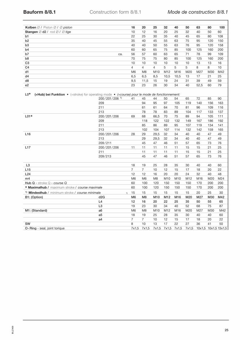
Kolben / Piston / piston 16 20 25 32 40 50 63 80 100Stangen d2 / rod / tige 10 12 16 20 25 32 40 50 60b1 22 25 30 35 40 45 65 80 108b2 35 40 45 55 63 75 95 120 150b3 40 40 50 55 63 76 95 120 158b4 60 60 65 75 85 100 125 160 200b7 ca. 56 57 60 63 65 71 78 99 109b8 70 75 75 80 85 100 125 160 200C3 10 10 10 10 10 10 13 13 16C4 4 4 4 5 5 5 8 8 10d1 M6 M8 M10 M12 M16 M20 M27 M30 M42d4 6,5 6,5 8,5 10,5 10,5 13 17 21 25d8 9,5 11,5 15 19 24 31 39 49 59e2 23 23 26 30 34 40 52,5 60 79
L0* (+Hub) bei Funktion • (+stroke) for operating mode • (+course) pour le mode de fonctionnement: 200 / 201/ 206 1) 41 45 44 50 54 65 72 85 90 209 94 95 97 105 119 140 156 163 211 61 61 64 70 81 96 109 116 213 78 78 83 89 104 117 133 137
L01* 200 / 201/ 206 69 68 66,5 70 75 89 94 105 111 209 118 122 122 132 149 167 186 192
211 85 86 89 95 107 119 134 141 213 102 104 107 114 132 142 159 165
L16 200 / 201/ 206 28 29 29,5 32 34 40 40 47 49 213 29 29,5 32 34 40 40 47 49
209 / 211 45 47 46 51 57 65 73 76L17 200 / 201/ 206 11 11 11 11 11 15 15 21 25 211 11 11 11 11 15 15 21 25
209/213 45 47 46 51 57 65 73 76
L3 18 19 25 28 35 30 40 40 60L15 7 7 10 12 15 17 18 20 22L24 12 12 16 20 20 24 32 40 48 m4 M6 M6 M8 M10 M10 M12 M16 M20 M24Hub Q - stroke Q - course Q 60 100 120 150 150 150 170 200 200
* Maximalhub / maximum stroke / course maximale 60 100 120 150 150 150 170 200 2001) Mindesthub / minimum stroke / course minimale 1) 15 15 15 15 15 15 20 25 30B1: (Option) d2G M6 M8 M10 M12 M16 M20 M27 M30 M42 L4 12 16 20 22 25 35 50 55 65 L3 19 23 30 34 40 52 68 75 87M1: (Standard) a6 M6 M8 M10 M12 M16 M20 M27 M30 M42 a5 18 19 25 28 35 30 40 40 60
a4 7 7 10 12 15 17 18 20 22SW 8 10 13 17 22 27 36 41 50O- Ring - seal, joint torique 7x1,5 7x1,5 7x1,5 7x1,5 7x1,5 7x1,5 10x1,5 10x1,5 13x1,5
Bauform 8/8.1 Construction form 8/8.1 Mode de construction 8/8.1
25
BL
Z40
0
Achtung - Typenbezeichnung bzw. Ident.Nr. sowie Kom.Nr. bei Ersatzbeschaffungund Ersatzteilbezug unbedingt angeben.
Attention - In case of order and purchase of spare parts it is absolutely necessary to indicatethe order specification or the number of identification as well as the commission number.
Attention - En cas d’acquisition des éléments de rechange indiquer absolutement la référencede commande ou bien le numéro d’identification ainsi que le numéro de commission.
Sämtliche Zylinder unserer Fertigung sind mit genauer Typenbezeichnung bzw. Ident.-Nr. und der Kom.-Nr., die zusätzlich eingraviertwird, gekennzeichnet. Eine absolut einwandfreie Identifizierung bei Ersatzteilbeschaffung und Ersatzteilbezug ist hierdurch gewährleistet.
All cylinders of our production are provided with the exact order specification respectively the number of identification and the commission num-ber which is additionally stamped on the cylinder. By this an absolutely perfect identification in case of order and purchase of spare parts is guaranteed.
Tous les cylindres de notre production sont marqués avec la référence de commande exacte ou bien le numéro d’identification et le numérode commission qui est estampé additionnellement. Une identification absolument correcte pour l’acquisition des éléments de rechange estgarantie par cela.
Änderungen vorbehalten.Subject to change without notice.Modification resérvée.
26
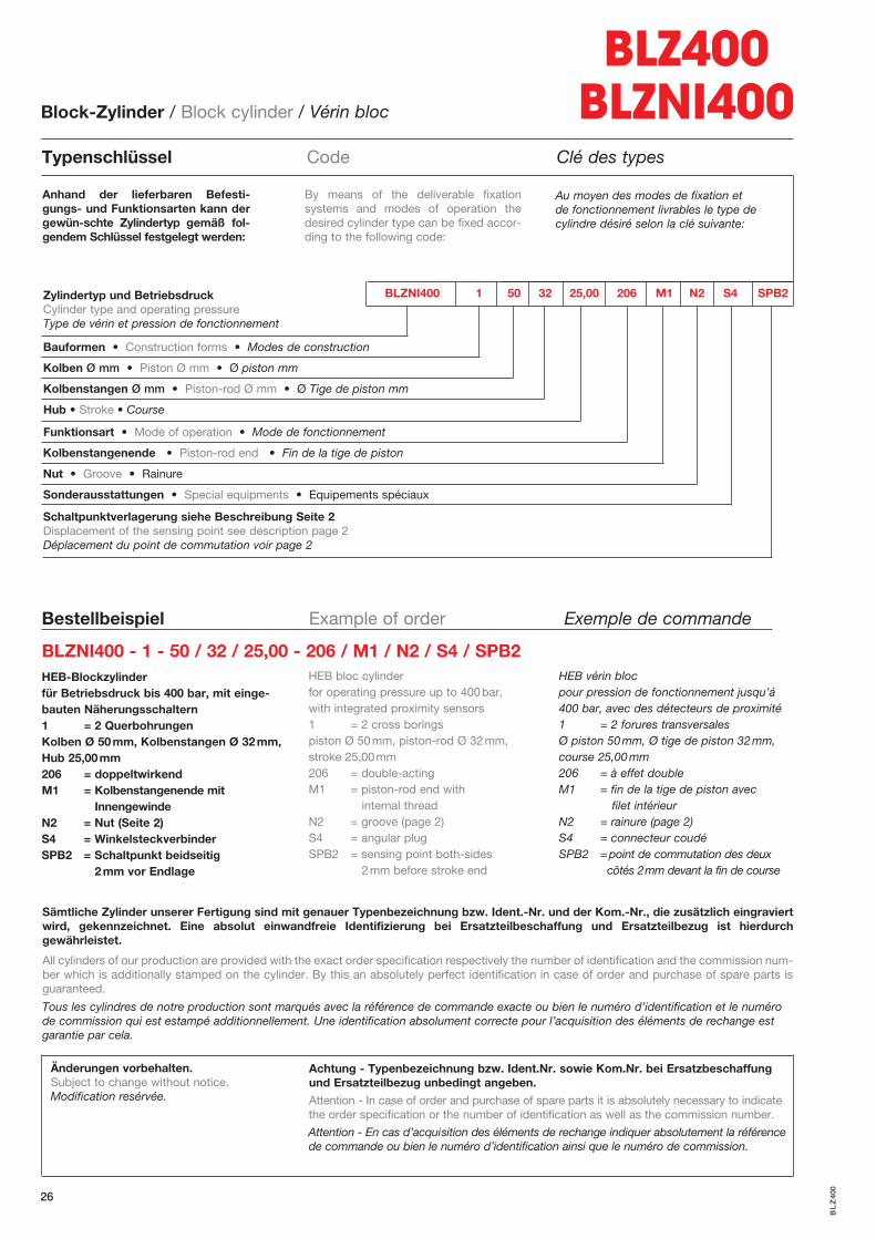
Bestellbeispiel Example of order Exemple de commande
HEB-Blockzylinderfür Betriebsdruck bis 400 bar, mit einge-bauten Näherungsschaltern1 = 2 QuerbohrungenKolben Ø 50mm, Kolbenstangen Ø 32mm,Hub 25,00mm206 = doppeltwirkendM1 = Kolbenstangenende mit InnengewindeN2 = Nut (Seite 2)S4 = WinkelsteckverbinderSPB2 = Schaltpunkt beidseitig 2mm vor Endlage
HEB bloc cylinderfor operating pressure up to 400bar, with integrated proximity sensors1 = 2 cross boringspiston Ø 50mm, piston-rod Ø 32mm,stroke 25,00mm206 = double-actingM1 = piston-rod end with internal threadN2 = groove (page 2)S4 = angular plugSPB2 = sensing point both-sides 2mm before stroke end
HEB vérin bloc pour pression de fonctionnement jusqu’á400 bar, avec des détecteurs de proximité1 = 2 forures transversalesØ piston 50mm, Ø tige de piston 32mm,course 25,00mm206 = à effet doubleM1 = fin de la tige de piston avec filet intérieurN2 = rainure (page 2)S4 = connecteur coudéSPB2 =point de commutation des deux côtés 2mm devant la fin de course
BLZNI400 - 1 - 50 / 32 / 25,00 - 206 / M1 / N2 / S4 / SPB2
Anhand der lieferbaren Befesti-gungs- und Funktionsarten kann dergewün-schte Zylindertyp gemäß fol-gendem Schlüssel festgelegt werden:
Au moyen des modes de fixation et de fonctionnement livrables le type de cylindre désiré selon la clé suivante:
By means of the deliverable fixation systems and modes of operation thedesired cylinder type can be fixed accor-ding to the following code:
Block-Zylinder / Block cylinder / Vérin bloc
Typenschlüssel Code Clé des types
BLZ400BLZNI400
BL
Z40
0
BLZNI400 1 50 32 25,00 206 M1 N2 S4 SPB2 Zylindertyp und BetriebsdruckCylinder type and operating pressureType de vérin et pression de fonctionnement
Bauformen • Construction forms • Modes de construction
Kolben Ø mm • Piston Ø mm • Ø piston mm
Kolbenstangen Ø mm • Piston-rod Ø mm • Ø Tige de piston mm
Hub • Stroke • Course
Funktionsart • Mode of operation • Mode de fonctionnement
Kolbenstangenende • Piston-rod end • Fin de la tige de piston
Nut • Groove • Rainure
Sonderausstattungen • Special equipments • Equipements spéciaux
Schaltpunktverlagerung siehe Beschreibung Seite 2 Displacement of the sensing point see description page 2 Déplacement du point de commutation voir page 2