Embed Size (px)
Citation preview
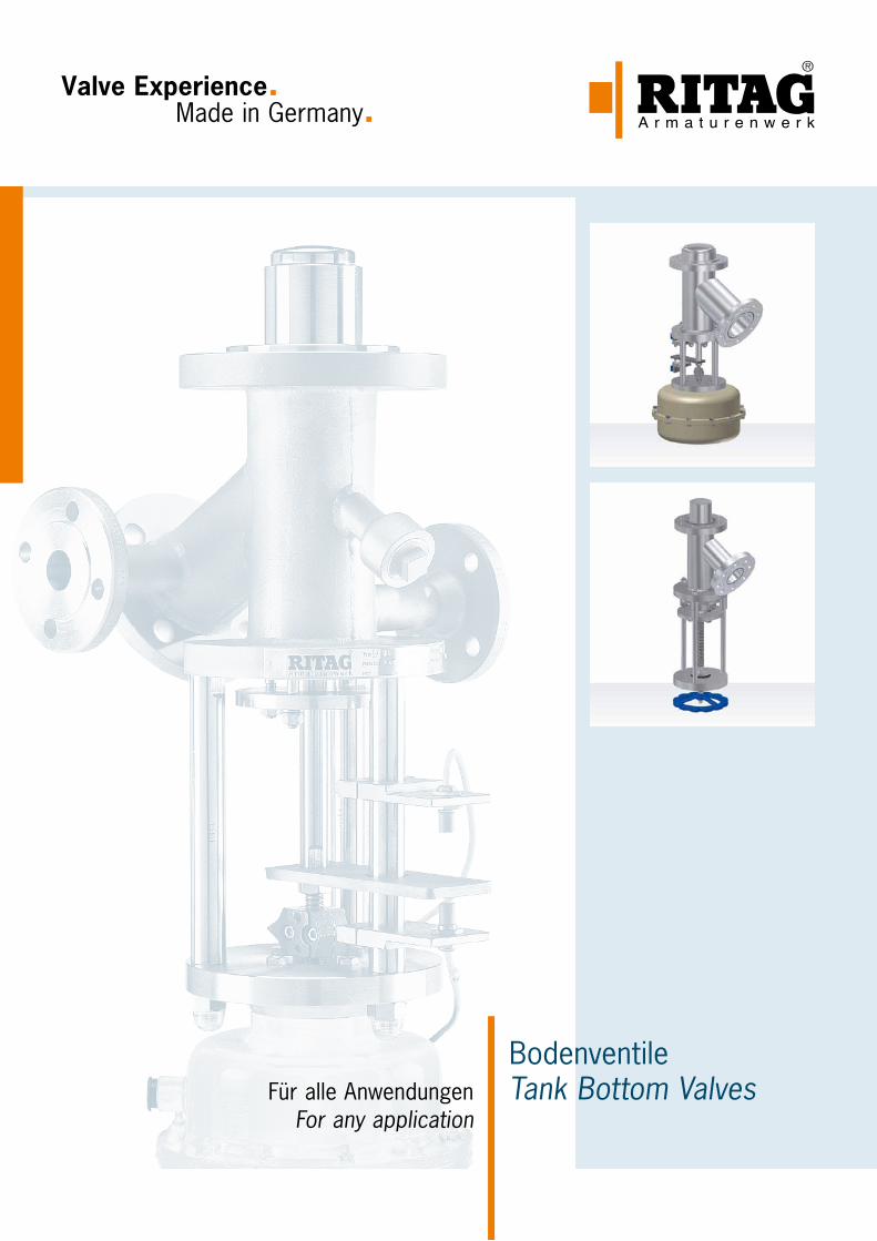
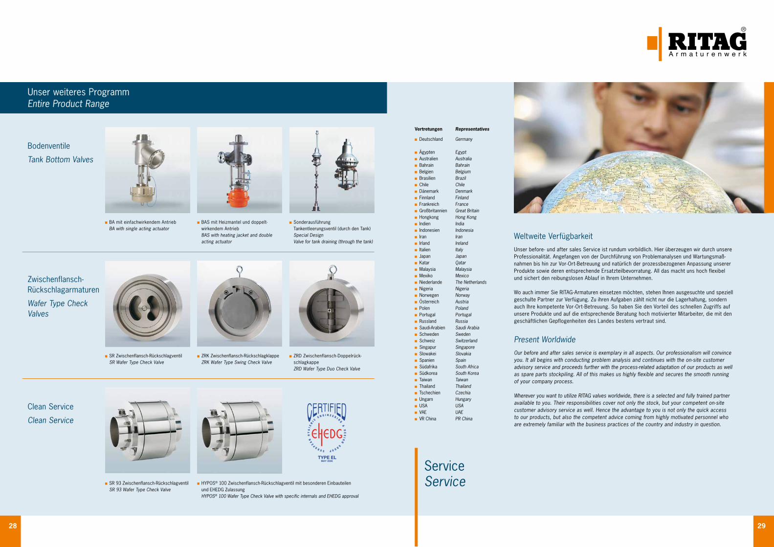
BodenventileTank Bottom ValvesFür alle Anwendungen
For any application
Valve Experience. Made in Germany.
1
InhaltsverzeichnisContents
Warum Bodenventile Why Tank Bottom Valves 2
Kriterien für den Einsatz von Bodenventilen Criteria for the Use of Tank Bottom Valves 3
Möglichkeiten Options 4
Ausführung Design 6
Antriebsvarianten Options of Actuation 7
Zubehör Accessoires 8
Beispiele Examples 10
Werkstoffe und Dichtungen Materials and Seat Rings 12
Prüfungen und Zertifikate Testings and Certificates 13
Abnahmen Inspections 14
Weiteres Programm Entire Product Range 16
Weltweite Verfügbarkeit Present Worldwide 17
Technische Änderungen vorbehalten 03/2015Technical modifications reserved 03/2015
Made in GermanyJahrzehntelange Erfahrungen und weltweite Referenzen für den Einsatz unserer Armaturen unter den extremen Einsatzbedingungen von Chemie, Pharma, Raffinerien und Anlagenbau bestätigen immer wieder die Leistungsfähigkeit unseres Unternehmens. Als ein weltweit führender Spezialist für die Planung, Konstruktion und Fertigung von Rückschlagarmaturen, Bodenventilen und Probe- nahmeventilen verbindet RITAG Produkte und Service zu maximalem Kundennutzen.
Prozesssicherheit durch erstklassiges Engineering. Flexibel und schnell in der Umsetzung Ihrer Wünsche und Anforderungen. Und nicht zuletzt: Höchste Verfügbarkeit Ihrer Anlagen und Systeme durch ein weltumspannendes Netz von Servicepartnern. RITAG Serienarmaturen sowie Sonder- ausführungen sind in allen prozesserforderlichen Nennweiten, Druckstufen und Werkstoffen liefer- bar. Unsere Ingenieure sorgen für eine Verwendbarkeit der RITAG Produkte nach allen internatio- nalen Normen und Vorschriften.
Made in GermanyDecades of experience and worldwide project references for the use of our non-return valves under the extreme operating conditions of the chemical and pharmaceutical industries, refineries and plant construction confirm our company’s high performance time and time again. As a world- leading specialist in the planning, design and manufacturing of check valves, bottom valves and sampling valves, RITAG focuses its products and service on achieving maximum customer benefit.
Process reliability through first-class engineering. Flexible and fast in realising your specifications and requirements. And last but not least: Maximum availability of your plant and systems by means of a global network of service partners. RITAG standard non-return valves and special designs are available in all nominal dimensions, pressure ratings and materials required for specific pro- cesses. Our engineers ensure that RITAG products operate in accordance with all international standards and regulations.
QualitätQuality
2 3
Kriterien für den Einsatz von BodenventilenCriteria for the Use of Tank Bottom Valves
Warum BodenventileWhy Tank Bottom Valves
Warum BodenventileFür die Behälterentleerung wird in der Regel eine normale Auf / Zu Armatur oder ein Kugelhahn benutzt. In den meisten Fällen ist das ausreichend. Es gibt jedoch auch Situationen, wo der Einsatz von Bodenventilen unbedingt erforderlich ist. Hierbei sind insbesondere die Einbausituation, das Medium, ein möglicher Totraum oder eine Krustenbildung zu nennen.
Auf den folgenden Seiten erhalten Sie einen Überblick über die Kriterien für den Einsatz von Bodenventilen und die verschiedenen Problemlösungen mit RITAG Bodenventilen. Darüber hinaus erhalten Sie Informationen zu den verfüg- baren Zubehörteilen.
Why Tank Bottom ValvesNormally, an ordinary Open / Closed valve or ball valve is used for draining a tank. For many cases, this is indeed sufficient. However, in some situation, the use of tank bottom valves is essential. Particular examples for such need include the situation of installation, media, possible dead space or crusting formation.
The following pages provide you with an overview of criteria for the use of tank bottom valves and various solutions by RITAG tank bottom valves. In addition, information on the available accessories is included.
Kriterien für den Einsatz von BodenventilenEs gibt verschiedene Gesichtspunkte, die beim Einsatz von Bodenventilen zu beachten sind. Die Hauptkriterien lassen sich hierbei mit folgenden Merkmalen beschreiben:
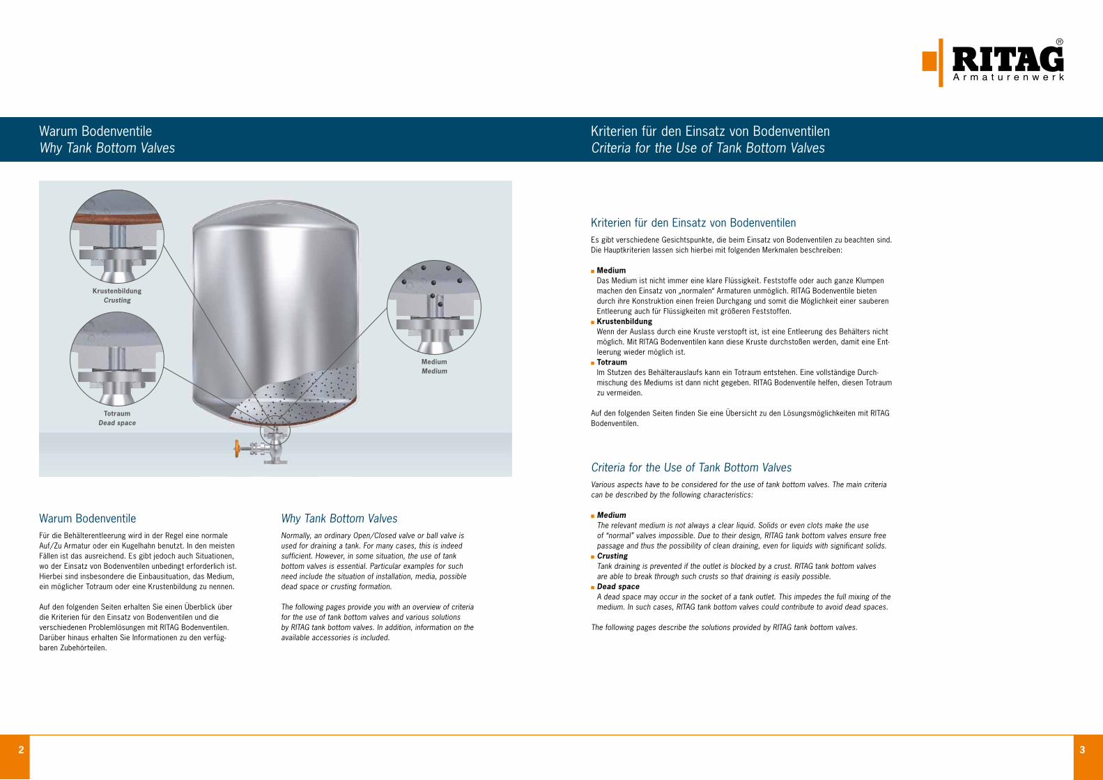
Medium Das Medium ist nicht immer eine klare Flüssigkeit. Feststoffe oder auch ganze Klumpen machen den Einsatz von „normalen“ Armaturen unmöglich. RITAG Bodenventile bieten durch ihre Konstruktion einen freien Durchgang und somit die Möglichkeit einer sauberen Entleerung auch für Flüssigkeiten mit größeren Feststoffen.
Krustenbildung Wenn der Auslass durch eine Kruste verstopft ist, ist eine Entleerung des Behälters nicht möglich. Mit RITAG Bodenventilen kann diese Kruste durchstoßen werden, damit eine Ent- leerung wieder möglich ist.
Totraum Im Stutzen des Behälterauslaufs kann ein Totraum entstehen. Eine vollständige Durch- mischung des Mediums ist dann nicht gegeben. RITAG Bodenventile helfen, diesen Totraum zu vermeiden.
Auf den folgenden Seiten finden Sie eine Übersicht zu den Lösungsmöglichkeiten mit RITAG Bodenventilen.
Criteria for the Use of Tank Bottom ValvesVarious aspects have to be considered for the use of tank bottom valves. The main criteria can be described by the following characteristics:
Medium The relevant medium is not always a clear liquid. Solids or even clots make the use of “normal” valves impossible. Due to their design, RITAG tank bottom valves ensure free passage and thus the possibility of clean draining, even for liquids with significant solids.
Crusting Tank draining is prevented if the outlet is blocked by a crust. RITAG tank bottom valves
are able to break through such crusts so that draining is easily possible. Dead space A dead space may occur in the socket of a tank outlet. This impedes the full mixing of the medium. In such cases, RITAG tank bottom valves could contribute to avoid dead spaces.
The following pages describe the solutions provided by RITAG tank bottom valves.
MediumMedium
TotraumDead space
KrustenbildungCrusting
4 5
MöglichkeitenOptions
Kegelventil Typ BA / Disc valve type BA Kolbenventil Typ BV / Piston valve type BV
Kegelventil Typ BAS / Disc valve type BAS Kolbenventil Typ BV / Piston valve type BV
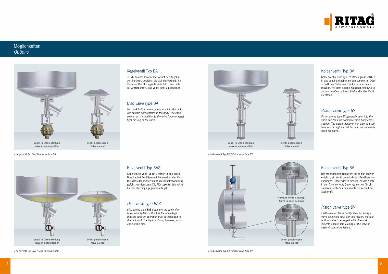
Kegelventil Typ BABei diesem Bodenventiltyp öffnet der Kegel in den Behälter. Lediglich die Spindel verbleibt im Gehäuse. Die Flüssigkeitssäule hilft zusätzlich zur Antriebskraft, das Ventil dicht zu schließen.
Disc valve type BAThis tank bottom valve type opens into the tank. The spindle only remains in the body. The liquid column acts in addition to the drive force to assist tight closing of the valve.
Kolbenventil Typ BVKolbenventile vom Typ BV öffnen grundsätzlich in das Ventil und geben so den kompletten Quer- schnitt des Gehäuses frei. Es ist aber auch möglich, mit dem Kolben zunächst eine Kruste zu durchstoßen und anschließend in das Ventil zu öffnen.
Piston valve type BVPiston valves type BV generally open into the valve and thus the complete valve body cross- section. The piston, however, can also be used to break through a crust first and subsequently open the valve.
Kegelventil Typ BASKegelventile vom Typ BAS öffnen in das Ventil. Dies hat bei Behältern mit Rührwerken den Vor- teil, dass der Rührer bis an die Behälterwandung geführt werden kann. Die Flüssigkeitssäule wirkt hierbei allerdings gegen den Kegel.
Disc valve type BASDisc valves type BAS open into the valve. For tanks with agitators, this has the advantage that the agitator operation may be extended to the tank wall. The liquid column, however, acts against the disc.
Kolbenventil Typ BVBei erdgedeckten Behältern ist es nur schwer möglich, ein Ventil unterhalb des Behälters an- zubringen. Daher wird in diesem Fall das Ventil in den Tank verlegt. Gewichte sorgen für ein sicheres Schließen des Ventils bei Ausfall der Steuerluft.
Piston valve type BVEarth-covered tanks hardly allow for fixing a valve below the tank. For this reason, the tank bottom valve is arranged within the tank. Weights ensure safe closing of the valve in case of control air failure.
Ventil in Offen-Stellung Valve in open position
Ventil geschlossen Valve closed
Ventil in Offen-Stellung Valve in open position
Ventil geschlossen Valve closed
Ventil in Offen-Stellung Valve in open position
Ventil geschlossen Valve closed
Ventil in Offen-Stellung Valve in open position
Ventil geschlossen Valve closed
6 7
Ausführung Design
Die AusführungRITAG Bodenventile werden grundsätzlich an die jeweilige Situation in der Anlage angepasst und in der Regel als Schweißkonstruktion ausgeführt. Dies hat gleich mehrere Vorteile. Zum einen können die Ein- und Austrittsnenn- weiten sowie der Auslaufwinkel angepasst werden und zum anderen werden mögliche Gussfehler vermieden.
Weiterhin können sehr schnell alle möglichen Sonderwerk- stoffe verarbeitet werden. Durch die austauschbare Sitz- buchse wird eine lange Stillstandszeit während der Wartung der Bodenventile vermieden.
Das modulare SystemNeben den vier auf den Seiten 4 und 5 beschriebenenGrundtypen der RITAG Bodenventile stehen eine Reihevon Zubehörteilen zur Verfügung. Die von unseren Kundenam häufigsten verwendeten sind die Folgenden:
Antriebe für Kegel- oder Kolbenventile Gelenkwellenverlängerung TA - Luft konforme Ausführung
(auch mit Faltenbalgabdichtung) Reinigungsstutzen Nicht steigendes Handrad Zylinderantrieb mit Federrückstellung Endlagenschalter Winkelgetriebe mit Gelenkwelle und Handrad Spezialkegel zur Dampfeinspeisung Spezialkegel mit Thermoelement Faltenbalg Stellungsregler Heizmantel Handnot
The DesignRITAG tank bottom valves are generally adapted to the relevant situation in the system and manufactured as a welded design on a standard basis. This has several advantages at a time. On the one hand, inlet and outlet nominal sizes as well as the outlet angle may be adjusted; on the other hand, casting defects are avoided.
In addition, any special materials may be processed quite rapidly. The interchangeable seat sleeve reduces shutdown times for bottom valve maintenance.
The modular systemIn addition to the basic types of RITAG bottom valves asdescribed on pages 4 and 5, a range of accessory com-ponents is available. Those used most by our customersare:
Actuators for disc- or piston valves Articulated shaft extension TA - Luft compliant design
(bellow seal possible) Cleaning socket Non-rising hand wheel “Spring-to-close” pneumatic cylinder Limit switch Angular gear with drive shaft and hand wheel Special disc for steam injection Special disc including thermocouple Bellow seal Positioner Heating jacket Emergency hand wheel
AntriebsvariantenOptions of Actuation
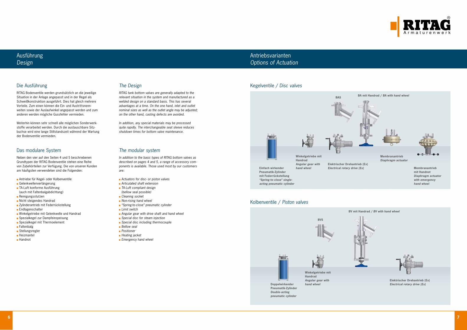
Kegelventile / Disc valves
Kolbenventile / Piston valves
BASBA mit Handrad / BA with hand wheel
Einfach wirkenderPneumatik-Zylindermit Federrückstellung“Spring-to-close” single-acting pneumatic cylinder
Winkelgetriebe mitHandradAngular gear withhand wheel
Elektrischer Drehantrieb (Ex)Electrical rotary drive (Ex)
MembranantriebDiaphragm actuator
Membranantriebmit HandnotDiaphragm actuatorwith emergencyhand wheel
BVS
BV mit Handrad / BV with hand wheel
Winkelgetriebe mitHandradAngular gear withhand wheel
Elektrischer Drehantrieb (Ex)Electrical rotary drive (Ex)Doppelwirkender
Pneumatik-ZylinderDouble-acting pneumatic cylinder
8 9
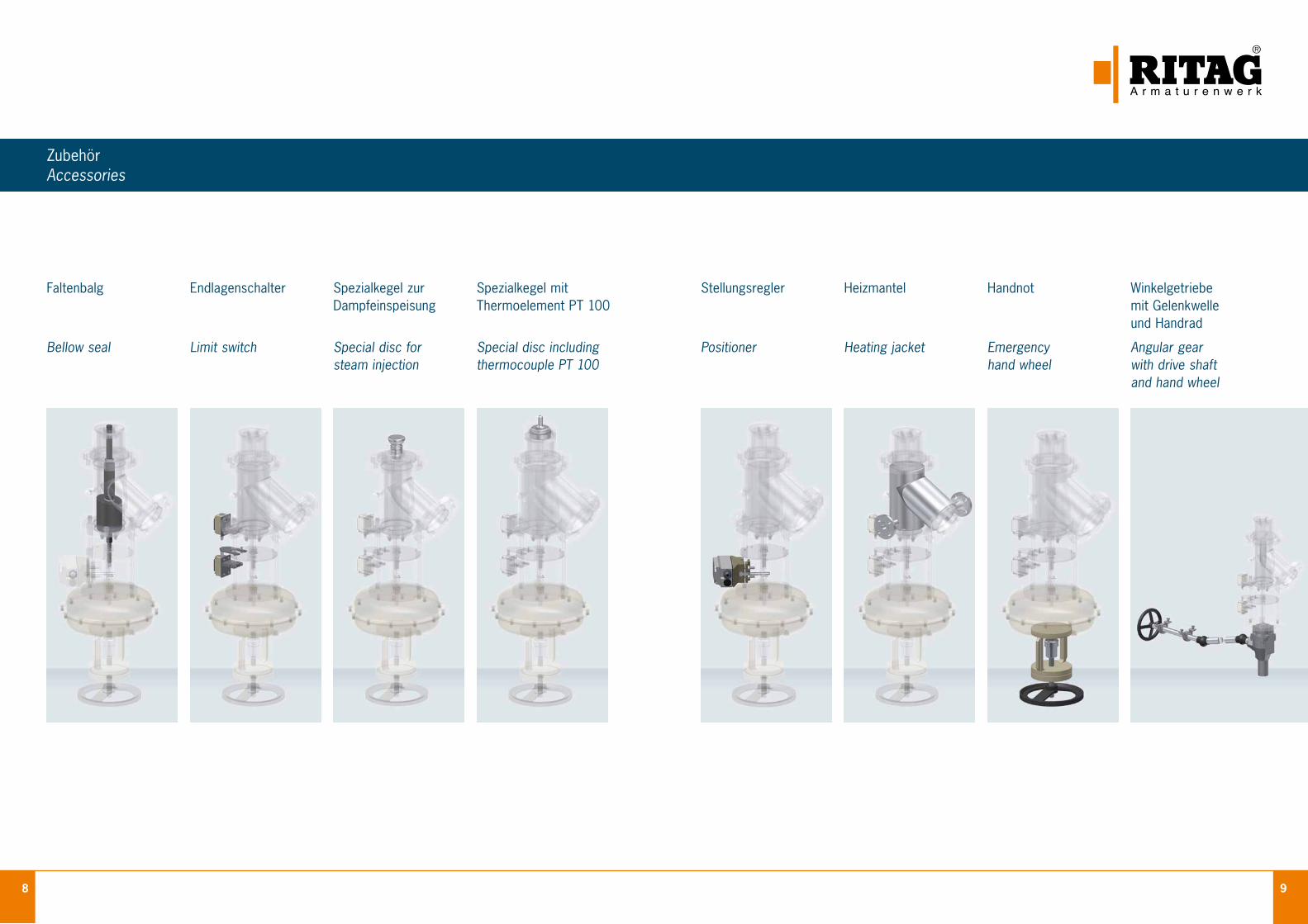
ZubehörAccessories
Winkelgetriebemit Gelenkwelleund Handrad
Angular gearwith drive shaft and hand wheel
Spezialkegel zurDampfeinspeisung
Special disc forsteam injection
Spezialkegel mitThermoelement PT 100
Special disc including thermocouple PT 100
Endlagenschalter
Limit switch
Stellungsregler
Positioner
Heizmantel
Heating jacket
Handnot
Emergency hand wheel
Faltenbalg
Bellow seal
10 11
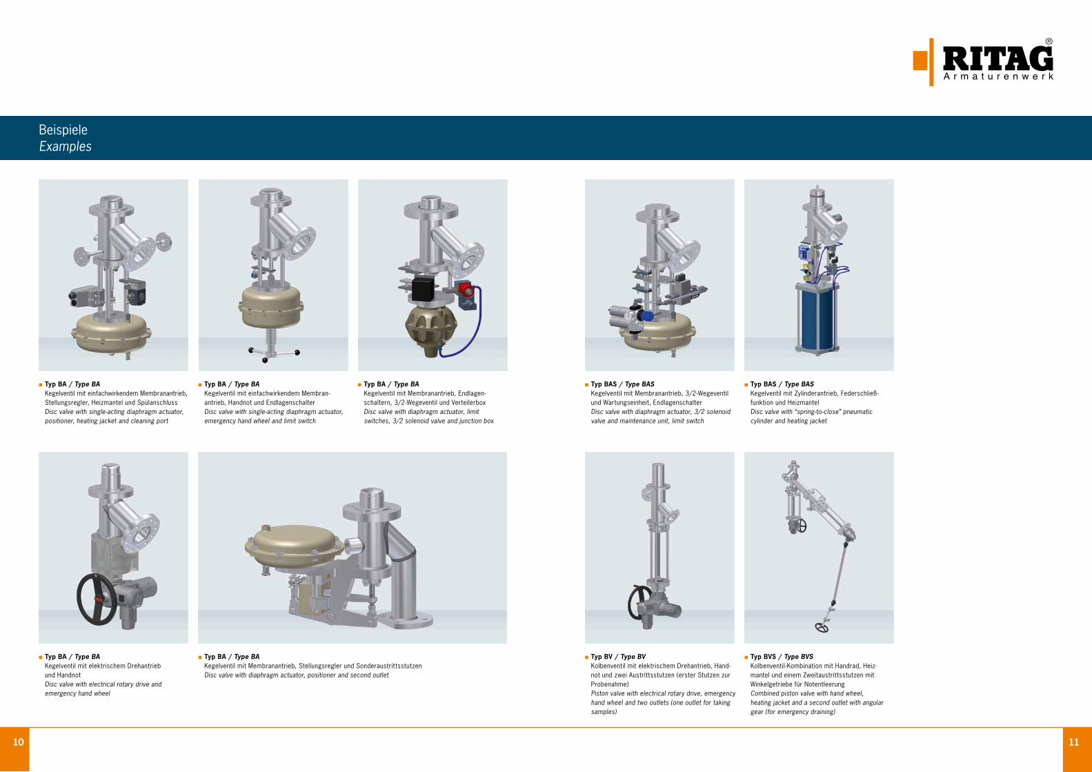
BeispieleExamples
Typ BA / Type BA Kegelventil mit einfachwirkendem Membranantrieb, Stellungsregler, Heizmantel und Spülanschluss Disc valve with single-acting diaphragm actuator, positioner, heating jacket and cleaning port
Typ BA / Type BA Kegelventil mit elektrischem Drehantrieb und Handnot Disc valve with electrical rotary drive and emergency hand wheel
Typ BA / Type BA Kegelventil mit einfachwirkendem Membran- antrieb, Handnot und Endlagenschalter Disc valve with single-acting diaphragm actuator, emergency hand wheel and limit switch
Typ BA / Type BA Kegelventil mit Membranantrieb, Endlagen- schaltern, 3/2 - Wegeventil und Verteilerbox Disc valve with diaphragm actuator, limit switches, 3/2 solenoid valve and junction box
Typ BAS / Type BAS Kegelventil mit Zylinderantrieb, Federschließ- funktion und Heizmantel Disc valve with “spring-to-close” pneumatic cylinder and heating jacket
Typ BAS / Type BAS Kegelventil mit Membranantrieb, 3/2 - Wegeventil und Wartungseinheit, Endlagenschalter Disc valve with diaphragm actuator, 3/2 solenoid valve and maintenance unit, limit switch
Typ BV / Type BV Kolbenventil mit elektrischem Drehantrieb, Hand- not und zwei Austrittsstutzen (erster Stutzen zur Probenahme) Piston valve with electrical rotary drive, emergency hand wheel and two outlets (one outlet for taking samples)
Typ BVS / Type BVS Kolbenventil-Kombination mit Handrad, Heiz- mantel und einem Zweitaustrittsstutzen mit Winkelgetriebe für Notentleerung Combined piston valve with hand wheel,
heating jacket and a second outlet with angular gear (for emergency draining)
Typ BA / Type BA Kegelventil mit Membranantrieb, Stellungsregler und Sonderaustrittsstutzen Disc valve with diaphragm actuator, positioner and second outlet
12 13
Werkstoffe und DichtungenMaterials and Seat Rings
Prüfungen und ZertifikateTestings and Certificates
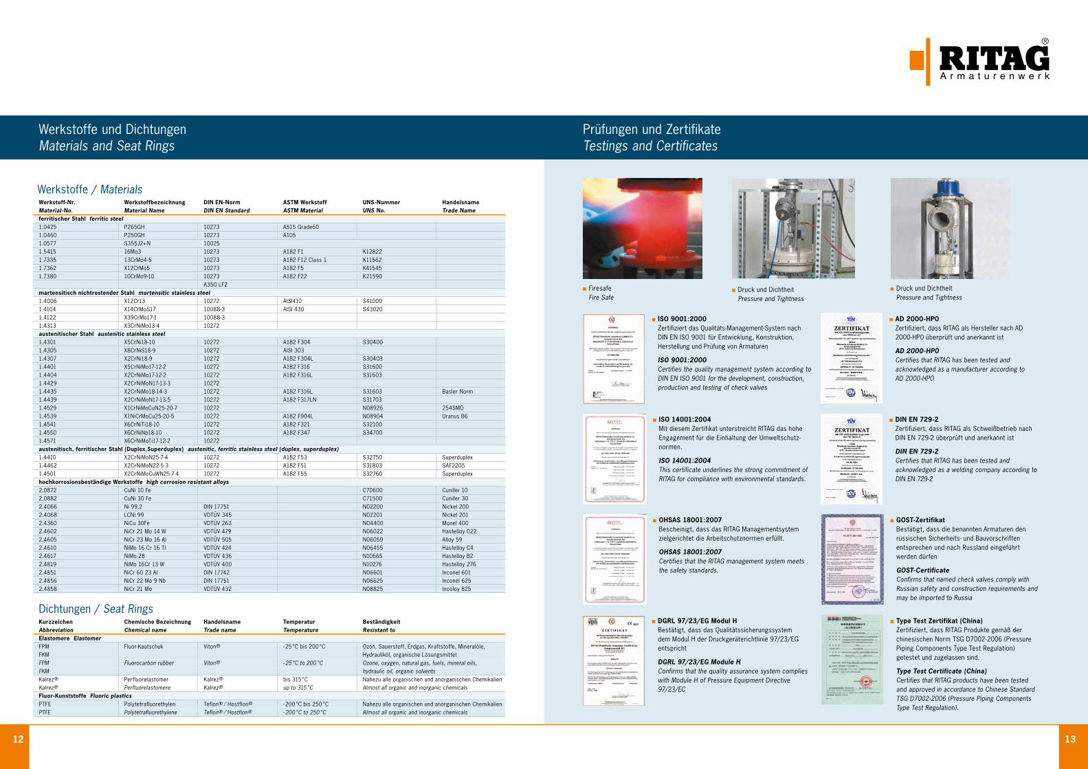
Druck und Dichtheit Pressure and Tightness
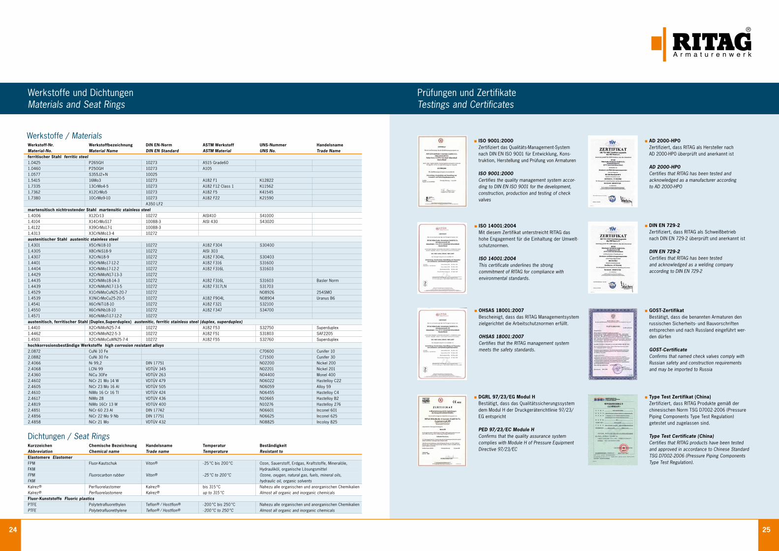
Werkstoff-Nr. Werkstoffbezeichnung DIN EN-Norm ASTM Werkstoff UNS-Nummer HandelsnameMaterial-No. Material Name DIN EN Standard ASTM Material UNS No. Trade Nameferritischer Stahl ferritic steel1.0425 P265GH 10273 A515 Grade60 1.0460 P250GH 10273 A105 1.0577 S355J2+N 10025 1.5415 16Mo3 10273 A182 F1 K12822 1.7335 13CrMo4-5 10273 A182 F12 Class 1 K11562 1.7362 X12CrMo5 10273 A182 F5 K41545 1.7380 10CrMo9-10 10273 A182 F22 K21590
A350 LF2martensitisch nichtrostender Stahl martensitic stainless steel 1.4006 X12Cr13 10272 AISI410 S41000 1.4104 X14CrMoS17 10088-3 AISI 430 S43020 1.4122 X39CrMo17-1 10088-3 1.4313 X3CrNiMo13-4 10272 austenitischer Stahl austenitic stainless steel 1.4301 X5CrNi18-10 10272 A182 F304 S30400 1.4305 X8CrNiS18-9 10272 AISI 303 1.4307 X2CrNi18-9 10272 A182 F304L S30403 1.4401 X5CrNiMo17-12-2 10272 A182 F316 S31600 1.4404 X2CrNiMo17-12-2 10272 A182 F316L S31603 1.4429 X2CrNiMoN17-13-3 10272 1.4435 X2CrNiMo18-14-3 10272 A182 F316L S31603 Basler Norm1.4439 X2CrNiMoN17-13-5 10272 A182 F317LN S31703 1.4529 X1CrNiMoCuN25-20-7 10272 N08926 254SMO 1.4539 X1NiCrMoCu25-20-5 10272 A182 F904L N08904 Uranus B61.4541 X6CrNiTi18-10 10272 A182 F321 S32100 1.4550 X6CrNiNb18-10 10272 A182 F347 S34700 1.4571 X6CrNiMoTi17-12-2 10272 austenitisch, ferritischer Stahl (Duplex,Superduplex) austenitic, ferritic stainless steel (duplex, superduplex)1.4410 X2CrNiMoN25-7-4 10272 A182 F53 S32750 Superduplex1.4462 X2CrNiMoN22-5-3 10272 A182 F51 S31803 SAF2205 1.4501 X2CrNiMoCuWN25-7-4 10272 A182 F55 S32760 Superduplex hochkorrosionsbeständige Werkstoffe high corrosion resistant alloys2.0872 CuNi 10 Fe C70600 Cunifer 102.0882 CuNi 30 Fe C71500 Cunifer 302.4066 Ni 99,2 DIN 17751 N02200 Nickel 2002.4068 LCNi 99 VDTÜV 345 N02201 Nickel 201 2.4360 NiCu 30Fe VDTÜV 263 N04400 Monel 4002.4602 NiCr 21 Mo 14 W VDTÜV 479 N06022 Hastelloy C22 2.4605 NiCr 23 Mo 16 Al VDTÜV 505 N06059 Alloy 59 2.4610 NiMo 16 Cr 16 TI VDTÜV 424 N06455 Hastelloy C42.4617 NiMo 28 VDTÜV 436 N10665 Hastelloy B22.4819 NiMo 16Cr 13 W VDTÜV 400 N10276 Hastelloy 2762.4851 NiCr 60 23 Al DIN 17742 N06601 Inconel 6012.4856 NiCr 22 Mo 9 Nb DIN 17751 N06625 Inconel 6252.4858 NiCr 21 Mo VDTÜV 432 N08825 Incoloy 825
Kurzzeichen Chemische Bezeichnung Handelsname Temperatur BeständigkeitAbbreviation Chemical name Trade name Temperature Resistant toElastomere ElastomerFPM Fluor-Kautschuk Viton ® - 25 °C bis 200 °C Ozon, Sauerstoff, Erdgas, Kraftstoffe, Mineralöle,FKM Hydrauliköl, organische LösungsmittelFPM Fluorocarbon rubber Viton ® - 25 °C to 200 °C Ozone, oxygen, natural gas, fuels, mineral oils,FKM hydraulic oil, organic solventsKalrez ® Perfluorelastomer Kalrez ® bis 315 °C Nahezu alle organischen und anorganischen ChemikalienKalrez ® Perfluorelastomere Kalrez ® up to 315 °C Almost all organic and inorganic chemicalsFluor-Kunststoffe Fluoric plasticsPTFE Polytetrafluorethylen Teflon ® / Hostflon ® - 200 °C bis 250 °C Nahezu alle organischen und anorganischen ChemikalienPTFE Polytetrafluorethylene Teflon ® / Hostflon ® - 200 °C to 250 °C Almost all organic and inorganic chemicals
Werkstoffe / Materials
Dichtungen / Seat Rings
Firesafe Fire Safe
Druck und Dichtheit Pressure and Tightness
ISO 9001:2000 Zertifiziert das Qualitäts-Management-System nach
DIN EN ISO 9001 für Entwicklung, Konstruktion, Herstellung und Prüfung von Armaturen
ISO 9001:2000 Certifies the quality management system according to DIN EN ISO 9001 for the development, construction, production and testing of check valves
DGRL 97/23/EG Modul H Bestätigt, dass das Qualitätssicherungssystem dem Modul H der Druckgeräterichtlinie 97/23/EG
entspricht
DGRL 97/23/EG Module H Confirms that the quality assurance system complies with Module H of Pressure Equipment Directive 97/23/EC
GOST-Zertifikat Bestätigt, dass die benannten Armaturen den
russischen Sicherheits- und Bauvorschriften entsprechen und nach Russland eingeführt
werden dürfen
GOST-Certificate Confirms that named check valves comply with Russian safety and construction requirements and may be imported to Russia
Type Test Zertifikat (China) Zertifiziert, dass RITAG Produkte gemäß der chinesischen Norm TSG D7002 - 2006 (Pressure
Piping Components Type Test Regulation) getestet und zugelassen sind.
Type Test Certificate (China) Certifies that RITAG products have been tested
and approved in accordance to Chinese Standard TSG D7002 - 2006 (Pressure Piping Components Type Test Regulation).
AD 2000-HP0 Zertifiziert, dass RITAG als Hersteller nach AD 2000-HP0 überprüft und anerkannt ist
AD 2000-HP0 Certifies that RITAG has been tested and acknowledged as a manufacturer according to
AD 2000-HPO
DIN EN 729-2 Zertifiziert, dass RITAG als Schweißbetrieb nach DIN EN 729-2 überprüft und anerkannt ist
DIN EN 729-2 Certifies that RITAG has been tested and acknowledged as a welding company according to DIN EN 729-2
ISO 14001:2004 Mit diesem Zertifikat unterstreicht RITAG das hohe
Engagement für die Einhaltung der Umweltschutz-normen.
ISO 14001:2004
This certificate underlines the strong commitment of RITAG for compliance with environmental standards.
OHSAS 18001:2007 Bescheinigt, dass das RITAG Managementsystem
zielgerichtet die Arbeitschutznormen erfüllt.
OHSAS 18001:2007 Certifies that the RITAG management system meets
the safety standards.
14 15
Abnahmen Inspections
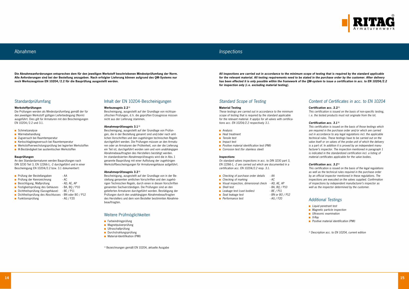
StandardprüfumfangWerkstoffprüfungenDie Prüfungen werden als Mindestprüfumfang gemäß der fürden jeweiligen Werkstoff gültigen Lieferbedingung (Norm)ausgeführt. Dies gilt für Armaturen mit den BescheinigungenEN 10204 / 2.2 und 3.1.
Schmelzanalyse Wärmebehandlung Zugversuch bei Raumtemperatur Kerbschlagbiegeversuch bei Raumtemperatur Werkstoffverwechslungsprüfung bei legierten Werkstoffen IK-Beständigkeit bei austenitischen Werkstoffen
BauprüfungenAn den Standardarmaturen werden Bauprüfungen nachDIN 3230 Teil 3, EN 12266-1, -2 durchgeführt und in einerBescheinigung EN 10204/2.2 bzw. 3.1 dokumentiert:
Prüfung der Bestellangaben - AA Prüfung der Kennzeichnung - AC Besichtigung, Maßprüfung - AD, AE, AP Festigkeitsprüfung des Gehäuses - BA, BQ / P10 Dichtheitsprüfung (Gussgehäuse) - BE / P11 Dichtheitsprüfung des Abschlusses - BN oder BO / P12 Funktionsprüfung - AG / F20
Inhalt der EN 10204 - BescheinigungenWerkszeugnis 2.2 1)
Bescheinigung, ausgestellt auf der Grundlage von nichtspe-zifischen Prüfungen, d. h. die geprüften Erzeugnisse müssennicht aus der Lieferung stammen.
Abnahmeprüfzeugnis 3.1 1)
Bescheinigung, ausgestellt auf der Grundlage von Prüfun-gen, die in der Bestellung genannt sind und/oder nach amt-lichen Vorschriften und den zugehörigen technischen Regelndurchgeführt werden. Die Prüfungen müssen an den Armatu-ren oder an Armaturen der Prüfeinheit, von der die Lieferungein Teil ist, durchgeführt worden sein und vom unabhängigenAbnahmebeauftragten des Herstellers bestätigt werden.Im standardisierten Abnahmeprüfzeugnis wird die in Abs. 1genannte Bauprüfung mit einer Auflistung der zugehörigenWerkstoffbescheinigungen für Armaturengehäuse aufgeführt.
Abnahmeprüfzeugnis 3.2 1)
Bescheinigung, ausgestellt auf der Grundlage von in der Be-stellung genannten amtlichen Vorschriften und den zugehö-rigen Technischen Regeln, durch einen in diesen Vorschriftengenannten Sachverständigen. Die Prüfungen sind an dengelieferten Armaturen durchgeführt worden. Bestätigung derPrüfungen durch den unabhängigen Abnahmebeauftragtendes Herstellers und dem vom Besteller bestimmten Abnahme-beauftragten.
Weitere Prüfmöglichkeiten Farbeindringprüfung Magnetpulverprüfung Ultraschallprüfung Durchstrahlungsprüfung Material-Identifikation (PMI)
1) Bezeichnungen gemäß EN 10204, aktuelle Ausgabe
Die Abnahmeanforderungen entsprechen dem für den jeweiligen Werkstoff beschriebenen Mindestprüfumfang der Norm.Alle Anforderungen sind bei der Bestellung anzugeben. Nach erfolgter Lieferung können aufgrund des QM-Systems nurnoch Werkszeugnisse EN 10204 / 2.2 für die Bauprüfung ausgestellt werden.
Standard Scope of TestingMaterial TestingThese testings are carried out in accordance to the minimumscope of testing that is required by the standard applicablefor the relevant material. It applys for all valves with certifica-tions acc. EN 10204/2.2 respectively 3.1.
Analysis Heat treatment Tensile test Impact test Positive material identification test (PMI) Corrosion test (for stainless steel)
InspectionsOn standard valves inspections in acc. to DIN 3230 part 3,EN 12266-1, -2 are carried out which are documented in acertification acc. EN 10204/2.2 resp. 3.1.
Checking of purchase order details - AA Checking of marking - AC Visual inspection, dimensional check - AD, AE, AP Shell test - BA, BQ / P10 Leakage test (cast bodies) - BE / P11 Seat leakage test - BN or BO / P12 Performance test - AG / F20
Content of Certificates in acc. to EN 10204Certification acc. 2.2 1)
This certification is issued on the basis of non-specific testing,i . e. the tested products must not originate from the lot.
Certification acc. 3.1 1)
This certification is issued on the basis of those testings whichare required in the purchase order and/or which are carriedout in accordance to any legal regulations incl. the applicabletechnical rules. These testings have to be carried out on thevalve itself or on valves of the probe unit of which the deliveryis a part of. In addition it is proved by an independent manu-facturer’s inspector. The inspection mentioned in paragraph 1is indicated in the standardized certification incl. a listing ofmaterial certificates applicable for the valve bodies.
Certification acc. 3.2 1)
This certification is issued on the basis of the legal regulationsas well as the technical rules required in the purchase orderby an official inspector mentioned in these regulations. Theinspections are executed on the valves supplied. Confirmationof inspections by independent manufacturer’s inspector aswell as the inspector determined by the customer.
Additional Testings Liquid penetrant test Magnetic particle inspection Ultrasonic examination X-Ray Positive material identification (PMI)
1) Description acc. to EN 10204, current edition
All inspections are carried out in accordance to the minimum scope of testing that is required by the standard applicablefor the relevant material. All testing requirements need to be stated in the purchase order by the customer. After deliveryhas been effected it is only possible within the framework of the QM-system to issue a certification in acc. to EN 10204/2.2for inspection only (i. e. excluding material testing).
16 17
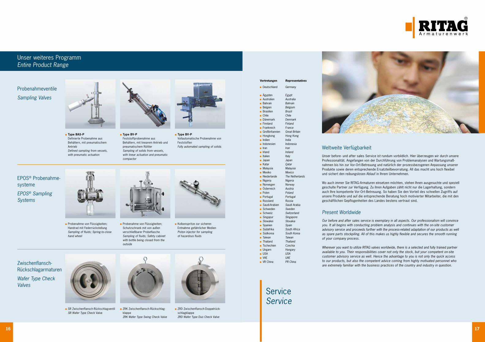
Type BAS - P Definierte Probenahme aus Behältern, mit pneumatischem Antrieb Defined sampling from vessels, with pneumatic actuation
Probenahme von Flüssigkeiten; Handrad mit Federrückstellung Sampling of fluids; Spring - to - close hand wheel
SR Zwischenflansch-Rückschlagventil SR Wafer Type Check Valve
ZRK Zwischenflansch-Rückschlag- klappe ZRK Wafer Type Swing Check Valve
ZRD Zwischenflansch-Doppelrück-schlagklappe ZRD Wafer Type Duo Check Valve
Probenahme von Flüssigkeiten; Schutzschrank mit von außen verschließbarer Probeflasche Sampling of fluids; Safety cabinet with bottle being closed from the outside
Kolbenspritze zur sicheren Entnahme gefährlicher Medien Piston injector for sampling of hazardous fluids
Type BV - P Feststoffprobenahme aus Behältern, mit linearem Antrieb und pneumatischem Rüttler Sampling of solids from vessels, with linear actuation and pneumatic compactor
Type BV - P Vollautomatische Probenahme von Feststoffen Fully automated sampling of solids
Unser weiteres ProgrammEntire Product Range
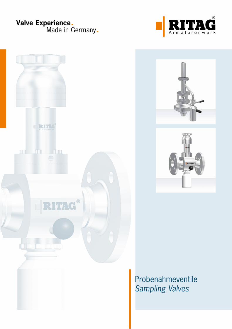
Probenahmeventile
Sampling Valves
EPOS® Probenahme- systeme
EPOS® Sampling Systems
Zwischenflansch- Rückschlagarmaturen
Wafer Type Check Valves
Weltweite VerfügbarkeitUnser before - und after sales Service ist rundum vorbildlich. Hier überzeugen wir durch unsere Professionalität. Angefangen von der Durchführung von Problemanalysen und Wartungsmaß- nahmen bis hin zur Vor - Ort - Betreuung und natürlich der prozessbezogenen Anpassung unserer Produkte sowie deren entsprechende Ersatzteilbevorratung. All das macht uns hoch flexibel und sichert den reibungslosen Ablauf in Ihrem Unternehmen.
Wo auch immer Sie RITAG - Armaturen einsetzen möchten, stehen Ihnen ausgesuchte und speziell geschulte Partner zur Verfügung. Zu ihren Aufgaben zählt nicht nur die Lagerhaltung, sondern auch Ihre kompetente Vor - Ort - Betreuung. So haben Sie den Vorteil des schnellen Zugriffs auf unsere Produkte und auf die entsprechende Beratung hoch motivierter Mitarbeiter, die mit den geschäftlichen Gepflogenheiten des Landes bestens vertraut sind.
Present WorldwideOur before and after sales service is exemplary in all aspects. Our professionalism will convince you. It all begins with conducting problem analysis and continues with the on-site customer advisory service and proceeds further with the process-related adaptation of our products as well as spare parts stockpiling. All of this makes us highly flexible and secures the smooth running of your company process.
Wherever you want to utilize RITAG valves worldwide, there is a selected and fully trained partner available to you. Their responsibilities cover not only the stock, but your competent on-site customer advisory service as well. Hence the advantage to you is not only the quick access to our products, but also the competent advice coming from highly motivated personnel who are extremely familiar with the business practices of the country and industry in question.
ServiceService
Vertretungen Representatives Deutschland Germany
Ägypten Egypt Australien Australia Bahrain Bahrain Belgien Belgium Brasilien Brazil Chile Chile Dänemark Denmark Finnland Finland Frankreich France Großbritannien Great Britain Hongkong Hong Kong Indien India Indonesien Indonesia Iran Iran Irland Ireland Italien Italy Japan Japan Katar Qatar Malaysia Malaysia Mexiko Mexico Niederlande The Netherlands Nigeria Nigeria Norwegen Norway Österreich Austria Polen Poland Portugal Portugal Russland Russia Saudi-Arabien Saudi Arabia Schweden Sweden Schweiz Switzerland Singapur Singapore Slowakei Slovakia Spanien Spain Südafrika South Africa Südkorea South Korea Taiwan Taiwan Thailand Thailand Tschechien Czechia Ungarn Hungary USA USA VAE UAE VR China PR China
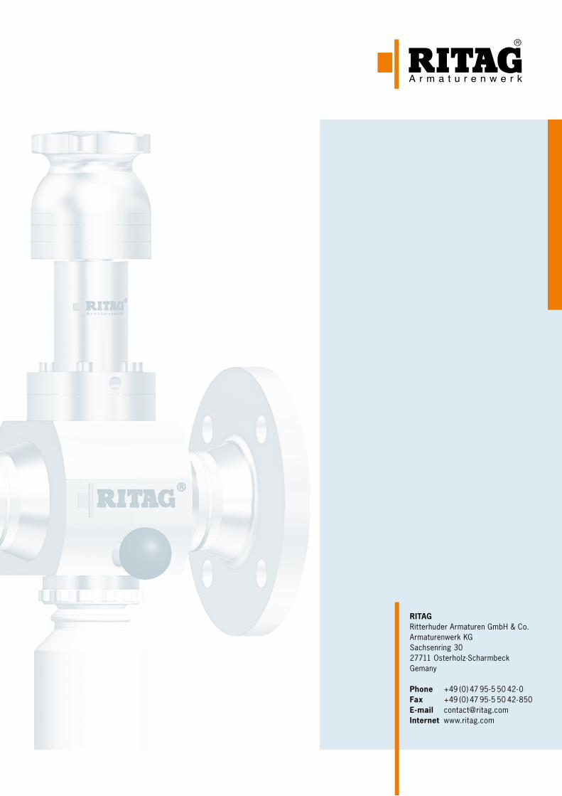
RITAGRitterhuder Armaturen GmbH & Co.Armaturenwerk KGSachsenring 3027711 Osterholz-ScharmbeckGemany
Phone +49 (0) 47 95 - 5 50 42 - 0Fax +49 (0) 47 95 - 5 50 42 - 850E-mail [email protected] www.ritag.com
ProbenahmeventileSampling Valves Für Flüssigkeiten und Feststoffe
For liquids and solids
Valve Experience. Made in Germany.
1
InhaltsverzeichnisContents
Warum Probenahme Why sampling 2
Kriterien für die Probenahme: Übersicht Criteria for Sampling: Overview 3
Kriterium: Sicherheitsgrad Criteria: Desired Degree of Safety 4
Kriterium: Einbausituation Criteria: Installation Situation 5
Kriterium: Medium Criteria: Medium 6
Kriterium: Betriebsbedingungen/Automatisationsgrad Criteria: Operating Conditions/Automation requirements 7
Probenahme aus dem Behälter Sampling from a Tank 8
Sonderlösungen Specialized Solutions 10
Feststoff-Probenahme Solids Sampling 11
Probenahme aus der Rohrleitung Pipe Sampling 12
EPOS® Aufbau EPOS® Structure 13
EPOS® Merkmale EPOS® Characteristics 14
EPOS® Zubehör EPOS® Accessories 16
EPOS® Schranksystem EPOS® Cabinet System 18
EPOS® Kolbenspritze EPOS® Piston Syringe 20
EPOS® Kombinationen EPOS® Combinations 22
Werkstoffe und Dichtungen Materials and Seat Rings 24
Prüfungen und Zertifikate Testings and Certificates 25
Abnahmen Inspections 26
Weiteres Programm Entire Product Range 28
Weltweite Verfügbarkeit Present Worldwide 29
Technische Änderungen vorbehalten 03/2015Technical modifications reserved 03/2015
Made in GermanyJahrzehntelange Erfahrungen und weltweite Referenzen für den Einsatz unserer Armaturen unter den extremen Einsatzbedingungen von Chemie, Pharma, Raffinerien und Anlagenbau bestätigen immer wieder die Leistungsfähigkeit unseres Unternehmens. Als ein weltweit führender Spezialist für die Planung, Konstruktion und Fertigung von Rückschlagarmaturen, Bodenventilen und Probe- nahmeventilen verbindet RITAG Produkte und Service zu maximalem Kundennutzen.
Prozesssicherheit durch erstklassiges Engineering. Flexibel und schnell in der Umsetzung Ihrer Wünsche und Anforderungen. Und nicht zuletzt: Höchste Verfügbarkeit Ihrer Anlagen und Systeme durch ein weltumspannendes Netz von Servicepartnern. RITAG Serienarmaturen sowie Sonder- ausführungen sind in allen prozesserforderlichen Nennweiten, Druckstufen und Werkstoffen liefer- bar. Unsere Ingenieure sorgen für eine Verwendbarkeit der RITAG Produkte nach allen internatio- nalen Normen und Vorschriften.
Made in GermanyDecades of experience and worldwide project references for the use of our non-return valves under the extreme operating conditions of the chemical and pharmaceutical industries, refineries and plant construction confirm our company’s high performance time and time again. As a world- leading specialist in the planning, design and manufacturing of check valves, bottom valves and sampling valves, RITAG focuses its products and service on achieving maximum customer benefit.
Process reliability through first-class engineering. Flexible and fast in realising your specifications and requirements. And last but not least: Maximum availability of your plant and systems by means of a global network of service partners. RITAG standard non-return valves and special designs are available in all nominal dimensions, pressure ratings and materials required for specific pro- cesses. Our engineers ensure that RITAG products operate in accordance with all international standards and regulations.
QualitätQuality
2 3
Kriterien für die ProbenahmeProbenahme ist nicht gleich Probenahme. Es gibt verschiedene Gesichtspunkte, die bei der Probenahme zu beachten sind. Die Hauptkriterien lassen sich hierbei mit folgenden Merk- malen beschreiben:
Sicherheitsgrad Sicherheit und Umweltschutz stehen im Mittelpunkt der Probenahme. Je nach Anforderungsgrad haben wir die richtige Lösung für Sie. Lesen Sie weiter auf Seite 4. Einbausituation Welches Probenahmeventil passt in mein System? RITAG bietet für jede Situation Standardprodukte oder individuell angepasste Lösungen. Eine Entscheidungshilfe bieten Ihnen die Informationen auf Seite 5. Medium Unterschiedliche Medien bei der Probenahme verlangen den Einsatz unterschiedlicher Dichtsysteme. Mehr lesen Sie auf Seite 6.Betriebsbedingungen Probenahme auch unter Druck oder Vakuum. Weitere Informationen auf Seite 7. Automatisationsgrad Probenahme mit automatisiertem Ablauf sehen Sie auf Seite 7.
Criteria for SamplingSampling is not always the same. There are various aspects which have to be observed for sam-pling. The main criteria may be described as follows:
Desired degree of safety The focus of sampling is on safety and environmental protec- tion. Depending on the degree of your requirements we are able to offer the appropriate solution. For details please refer to page 4. Installation situation What type of sampling valve might suit my system? RITAG offers standard products for any situation or sophisticated individual solutions. The details on page 5 provide you a decision support.Type of medium Different media require different sealing systems. For details please refer to page 6.Operation conditions Sampling also under pressure or vacuum conditions. For further details please refer to page 7.Automation requirements Details on automated sampling are given on page 7.
Kriterien für die Probenahme: ÜbersichtCriteria for Sampling: Overview
Warum ProbenahmeWhy sampling
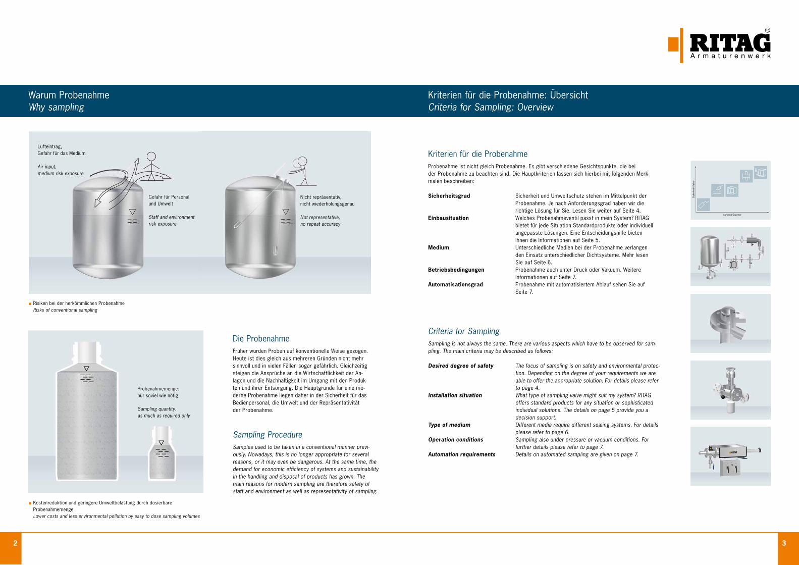
Die ProbenahmeFrüher wurden Proben auf konventionelle Weise gezogen. Heute ist dies gleich aus mehreren Gründen nicht mehr sinnvoll und in vielen Fällen sogar gefährlich. Gleichzeitig steigen die Ansprüche an die Wirtschaftlichkeit der An- lagen und die Nachhaltigkeit im Umgang mit den Produk- ten und ihrer Entsorgung. Die Hauptgründe für eine mo- derne Probenahme liegen daher in der Sicherheit für das Bedienpersonal, die Umwelt und der Repräsentativität der Probenahme.
Sampling ProcedureSamples used to be taken in a conventional manner previ-ously. Nowadays, this is no longer appropriate for several reasons, or it may even be dangerous. At the same time, the demand for economic efficiency of systems and sustainability in the handling and disposal of products has grown. The main reasons for modern sampling are therefore safety of staff and environment as well as representativity of sampling.
Risiken bei der herkömmlichen Probenahme Risks of conventional sampling
Kostenreduktion und geringere Umweltbelastung durch dosierbare Probenahmemenge Lower costs and less environmental pollution by easy to dose sampling volumes
Lufteintrag, Gefahr für das Medium
Air input,medium risk exposure
Gefahr für Personal und Umwelt
Staff and environment risk exposure
Nicht repräsentativ, nicht wiederholungsgenau
Not representative,no repeat accuracy
Probenahmemenge: nur soviel wie nötig
Sampling quantity:as much as required only
Aufwand/ Expense
Sich
erhe
it / S
afet
y
4 5
Kriterium: Sicherheitsgrad Criteria: Desired Degree of Safety
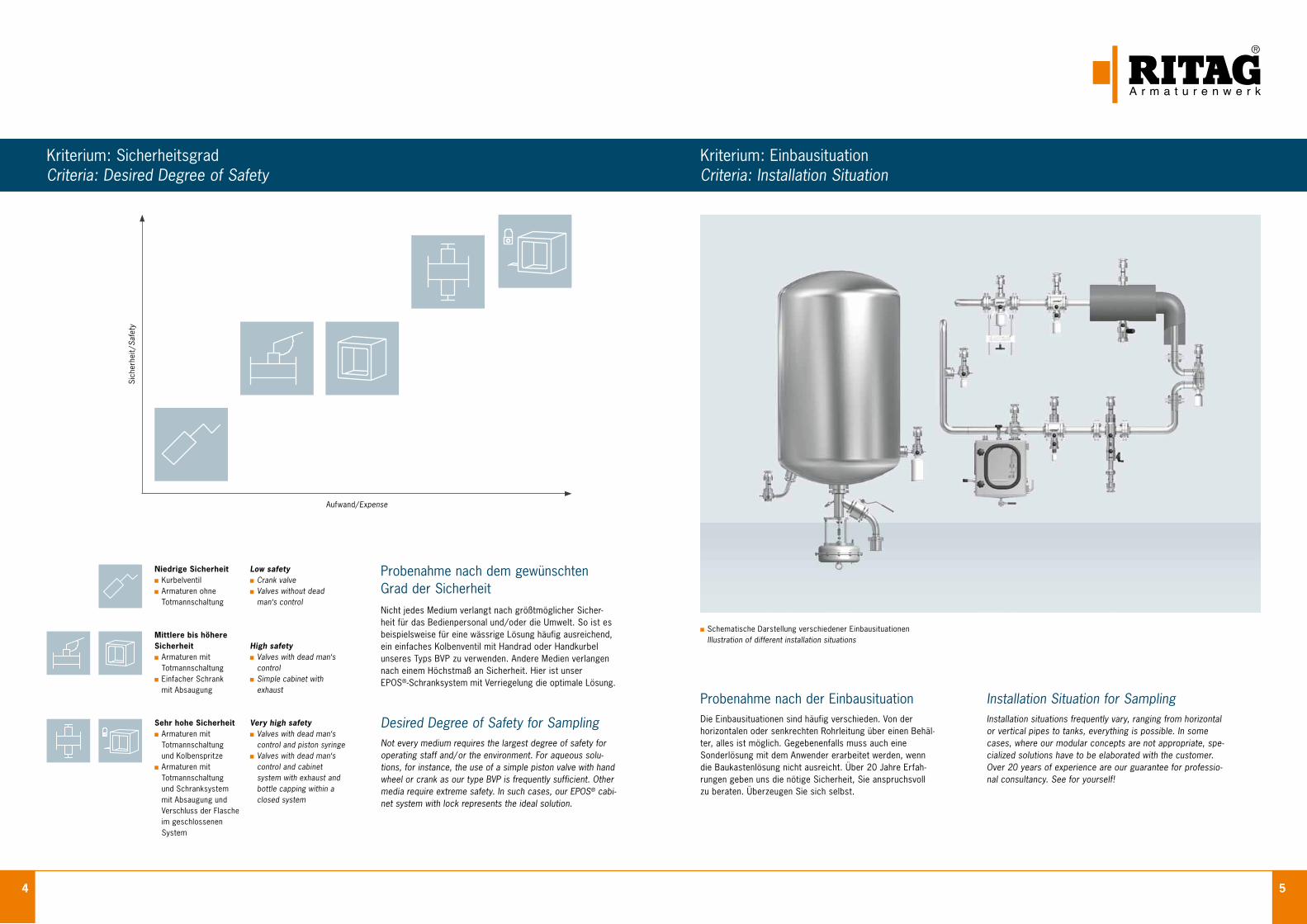
Nicht jedes Medium verlangt nach größtmöglicher Sicher- heit für das Bedienpersonal und / oder die Umwelt. So ist es beispielsweise für eine wässrige Lösung häufig ausreichend, ein einfaches Kolbenventil mit Handrad oder Handkurbel unseres Typs BVP zu verwenden. Andere Medien verlangen nach einem Höchstmaß an Sicherheit. Hier ist unser EPOS®-Schranksystem mit Verriegelung die optimale Lösung.
Probenahme nach dem gewünschtenGrad der Sicherheit
Not every medium requires the largest degree of safety for operating staff and / or the environment. For aqueous solu-tions, for instance, the use of a simple piston valve with hand wheel or crank as our type BVP is frequently sufficient. Other media require extreme safety. In such cases, our EPOS® cabi-net system with lock represents the ideal solution.
Desired Degree of Safety for Sampling
Niedrige Sicherheit Kurbelventil Armaturen ohne
Totmannschaltung
Mittlere bis höhere Sicherheit Armaturen mit
Totmannschaltung Einfacher Schrank
mit Absaugung
Sehr hohe Sicherheit Armaturen mit
Totmannschaltung und Kolbenspritze
Armaturen mit Totmannschaltung
und Schranksystem mit Absaugung und Verschluss der Flasche im geschlossenen System
Low safety Crank valve Valves without dead man‘s control
High safety Valves with dead man‘s control
Simple cabinet with exhaust
Very high safety Valves with dead man‘s control and piston syringe
Valves with dead man‘s control and cabinet system with exhaust and bottle capping within a closed system
Installation Situation for SamplingInstallation situations frequently vary, ranging from horizontal or vertical pipes to tanks, everything is possible. In some cases, where our modular concepts are not appropriate, spe-cialized solutions have to be elaborated with the customer. Over 20 years of experience are our guarantee for professio-nal consultancy. See for yourself!
Probenahme nach der EinbausituationDie Einbausituationen sind häufig verschieden. Von der horizontalen oder senkrechten Rohrleitung über einen Behäl-ter, alles ist möglich. Gegebenenfalls muss auch eine Sonderlösung mit dem Anwender erarbeitet werden, wenn die Baukastenlösung nicht ausreicht. Über 20 Jahre Erfah-rungen geben uns die nötige Sicherheit, Sie anspruchsvoll zu beraten. Überzeugen Sie sich selbst.
Schematische Darstellung verschiedener Einbausituationen Illustration of different installation situations
Kriterium: EinbausituationCriteria: Installation Situation
Aufwand/ Expense
Sich
erhe
it / S
afet
y
6 7
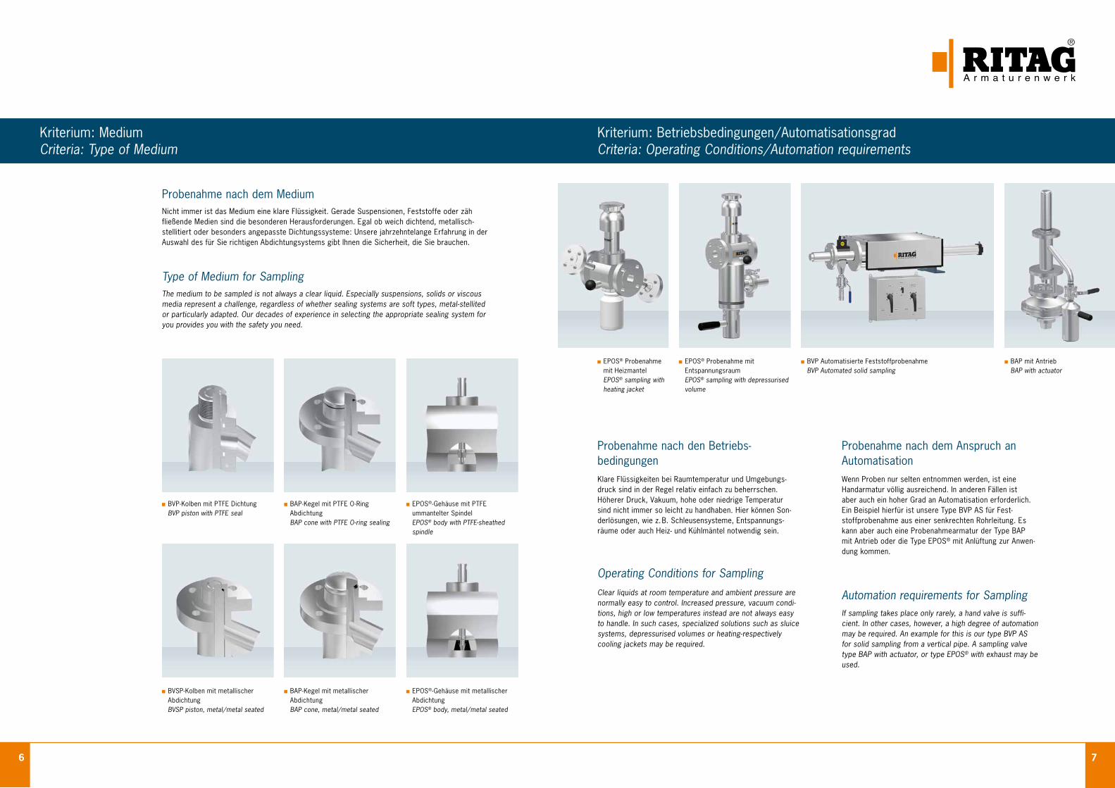
EPOS® Probenahme mit Heizmantel EPOS® sampling with heating jacket
EPOS® Probenahme mit Entspannungsraum
EPOS® sampling with depressurised volume
Kriterium: Medium Criteria: Type of Medium
BVSP-Kolben mit metallischer Abdichtung
BVSP piston, metal / metal seated
BAP-Kegel mit metallischer Abdichtung BAP cone, metal/ metal seated
EPOS®-Gehäuse mit metallischer Abdichtung EPOS® body, metal/ metal seated
Probenahme nach dem MediumNicht immer ist das Medium eine klare Flüssigkeit. Gerade Suspensionen, Feststoffe oder zäh fließende Medien sind die besonderen Herausforderungen. Egal ob weich dichtend, metallisch- stellitiert oder besonders angepasste Dichtungssysteme: Unsere jahrzehntelange Erfahrung in der Auswahl des für Sie richtigen Abdichtungsystems gibt Ihnen die Sicherheit, die Sie brauchen.
Type of Medium for SamplingThe medium to be sampled is not always a clear liquid. Especially suspensions, solids or viscous media represent a challenge, regardless of whether sealing systems are soft types, metal-stellited or particularly adapted. Our decades of experience in selecting the appropriate sealing system for you provides you with the safety you need.
Wenn Proben nur selten entnommen werden, ist eine Handarmatur völlig ausreichend. In anderen Fällen ist aber auch ein hoher Grad an Automatisation erforderlich. Ein Beispiel hierfür ist unsere Type BVP AS für Fest- stoffprobenahme aus einer senkrechten Rohrleitung. Es kann aber auch eine Probenahmearmatur der Type BAP mit Antrieb oder die Type EPOS® mit Anlüftung zur Anwen-dung kommen.
Probenahme nach dem Anspruch an Automatisation
If sampling takes place only rarely, a hand valve is suffi-cient. In other cases, however, a high degree of automation may be required. An example for this is our type BVP AS for solid sampling from a vertical pipe. A sampling valve type BAP with actuator, or type EPOS® with exhaust may be used.
Automation requirements for Sampling
Klare Flüssigkeiten bei Raumtemperatur und Umgebungs- druck sind in der Regel relativ einfach zu beherrschen. Höherer Druck, Vakuum, hohe oder niedrige Temperatur sind nicht immer so leicht zu handhaben. Hier können Son-derlösungen, wie z. B. Schleusensysteme, Entspannungs-räume oder auch Heiz- und Kühlmäntel notwendig sein.
Probenahme nach den Betriebs-bedingungen
Clear liquids at room temperature and ambient pressure are normally easy to control. Increased pressure, vacuum condi- tions, high or low temperatures instead are not always easy to handle. In such cases, specialized solutions such as sluice systems, depressurised volumes or heating-respectively cooling jackets may be required.
Operating Conditions for Sampling
BVP-Kolben mit PTFE Dichtung BVP piston with PTFE seal
BAP-Kegel mit PTFE O-Ring Abdichtung
BAP cone with PTFE O-ring sealing
EPOS®-Gehäuse mit PTFE ummantelter Spindel EPOS® body with PTFE-sheathed spindle
BVP Automatisierte Feststoffprobenahme BVP Automated solid sampling
BAP mit Antrieb BAP with actuator
Kriterium: Betriebsbedingungen / AutomatisationsgradCriteria: Operating Conditions / Automation requirements
8 9
Probenahme aus dem BehälterSampling from a Tank
Probenahme aus dem BehälterSampling from a Tank
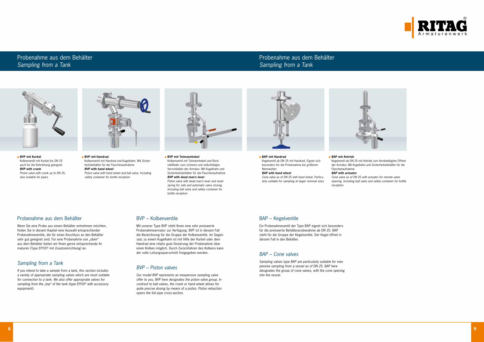
BAP – KegelventileEin Probenahmeventil der Type BAP eignet sich besonders für die preiswerte Behälterprobenahme ab DN 25. BAP steht für die Gruppe der Kegelventile. Der Kegel öffnet in diesem Fall in den Behälter.
BAP – Cone valvesSampling valves type BAP are particularly suitable for inex-pensive sampling from a vessel as of DN 25. BAP here designates the group of cone valves, with the cone opening into the vessel.
BAP mit Handrad Kegelventil ab DN 25 mit Handrad. Eignet sich
besonders für die Probenahme bei größeren Nennweiten BAP with hand wheel
Cone valve as of DN 25 with hand wheel. Partic u-larly suitable for sampling at larger nominal sizes
BAP mit Antrieb Kegelventil ab DN 25 mit Antrieb zum fernbetätigten Öffnen
der Armatur. Mit Kugelhahn und Sicherheitsbehälter für die Flaschenaufnahme
BAP with actuator Cone valve as of DN 25 with actuator for remote valve
opening. Including ball valve and safety container for bottle reception
BVP – KolbenventileMit unserer Type BVP steht Ihnen eine sehr preiswerte Probenahmearmatur zur Verfügung. BVP ist in diesem Fall die Bezeichnung für die Gruppe der Kolbenventile. Im Gegen-satz zu einem Kugelhahn ist mit Hilfe der Kurbel oder dem Handrad eine relativ gute Dosierung der Probenahme über einen Kolben möglich. Durch Zurückfahren des Kolbens kann der volle Leitungsquerschnitt freigegeben werden.
BVP – Piston valvesOur model BVP represents an inexpensive sampling valve offer to you. BVP here designates the piston valve group. In contrast to ball valves, the crank or hand wheel allows for quite precise dosing by means of a piston. Piston retraction opens the full pipe cross-section.
Probenahme aus dem BehälterWenn Sie eine Probe aus einem Behälter entnehmen möchten,finden Sie in diesem Kapitel eine Auswahl entsprechender Probenahmeventile, die für einen Anschluss an den Behältersehr gut geeignet sind. Für eine Probenahme von „oben“ aus dem Behälter bieten wir Ihnen gerne entsprechende Ar-maturen (Type EPOS® mit Zusatzeinrichtung) an.
Sampling from a TankIf you intend to take a sample from a tank, this section includesa variety of appropriate sampling valves which are most suitable for connection to a tank. We also offer appropriate valves forsampling from the „top“ of the tank (type EPOS® with accessoryequipment).
BVP mit Kurbel Kolbenventil mit Kurbel bis DN 25 auch für die Rohrleitung geeignet. BVP with crank Piston valve with crank up to DN 25, also suitable for pipes.
BVP mit Handrad Kolbenventil mit Handrad und Kugelhahn. Mit Sicher-
heitsbehälter für die Flaschenaufnahme BVP with hand wheel
Piston valve with hand wheel and ball valve. Including safety container for bottle reception
BVP mit Totmannhebel Kolbenventil mit Totmannhebel und Rück-
stellfeder zum sicheren und selbsttätigen Verschließen der Armatur. Mit Kugelhahn und Sicherheitsbehälter für die Flaschenaufnahme
BVP with dead man‘s lever Piston valve with dead man‘s lever and reset
spring for safe and automatic valve closing. Including ball valve and safety container for bottle reception
10 11
Feststoff-ProbenahmeSolids Sampling
SonderlösungSpecialized Solutions
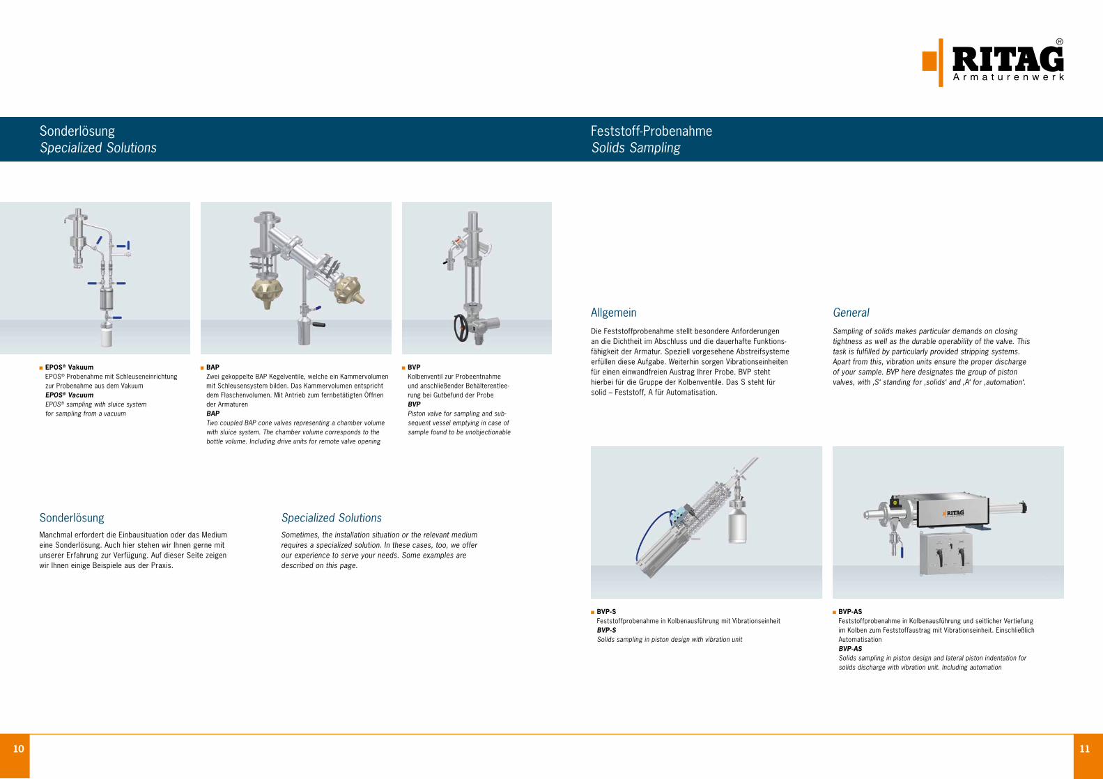
SonderlösungManchmal erfordert die Einbausituation oder das Medium eine Sonderlösung. Auch hier stehen wir Ihnen gerne mit unserer Erfahrung zur Verfügung. Auf dieser Seite zeigen wir Ihnen einige Beispiele aus der Praxis.
AllgemeinDie Feststoffprobenahme stellt besondere Anforderungen an die Dichtheit im Abschluss und die dauerhafte Funktions-fähigkeit der Armatur. Speziell vorgesehene Abstreifsysteme erfüllen diese Aufgabe. Weiterhin sorgen Vibrationseinheiten für einen einwandfreien Austrag Ihrer Probe. BVP steht hierbei für die Gruppe der Kolbenventile. Das S steht für solid – Feststoff, A für Automatisation.
GeneralSampling of solids makes particular demands on closing tightness as well as the durable operability of the valve. This task is fulfilled by particularly provided stripping systems. Apart from this, vibration units ensure the proper discharge of your sample. BVP here designates the group of piston valves, with ‚S‘ standing for ‚solids‘ and ‚A‘ for ‚automation‘.
BVP-S Feststoffprobenahme in Kolbenausführung mit Vibrationseinheit
BVP-S Solids sampling in piston design with vibration unit
BVP-AS Feststoffprobenahme in Kolbenausführung und seitlicher Vertiefung
im Kolben zum Feststoffaustrag mit Vibrationseinheit. Einschließlich Automatisation BVP-AS
Solids sampling in piston design and lateral piston indentation for solids discharge with vibration unit. Including automation
Specialized SolutionsSometimes, the installation situation or the relevant medium requires a specialized solution. In these cases, too, we offer our experience to serve your needs. Some examples are described on this page.
BVP Kolbenventil zur Probeentnahme und anschließender Behälterentlee-rung bei Gutbefund der Probe BVP Piston valve for sampling and sub-sequent vessel emptying in case of sample found to be unobjectionable
BAP Zwei gekoppelte BAP Kegelventile, welche ein Kammervolumen
mit Schleusensystem bilden. Das Kammervolumen entspricht dem Flaschenvolumen. Mit Antrieb zum fernbetätigten Öffnen der Armaturen BAP Two coupled BAP cone valves representing a chamber volume with sluice system. The chamber volume corresponds to the bottle volume. Including drive units for remote valve opening
EPOS® Vakuum EPOS® Probenahme mit Schleuseneinrichtung
zur Probenahme aus dem Vakuum EPOS® Vacuum
EPOS® sampling with sluice system for sampling from a vacuum
12 13
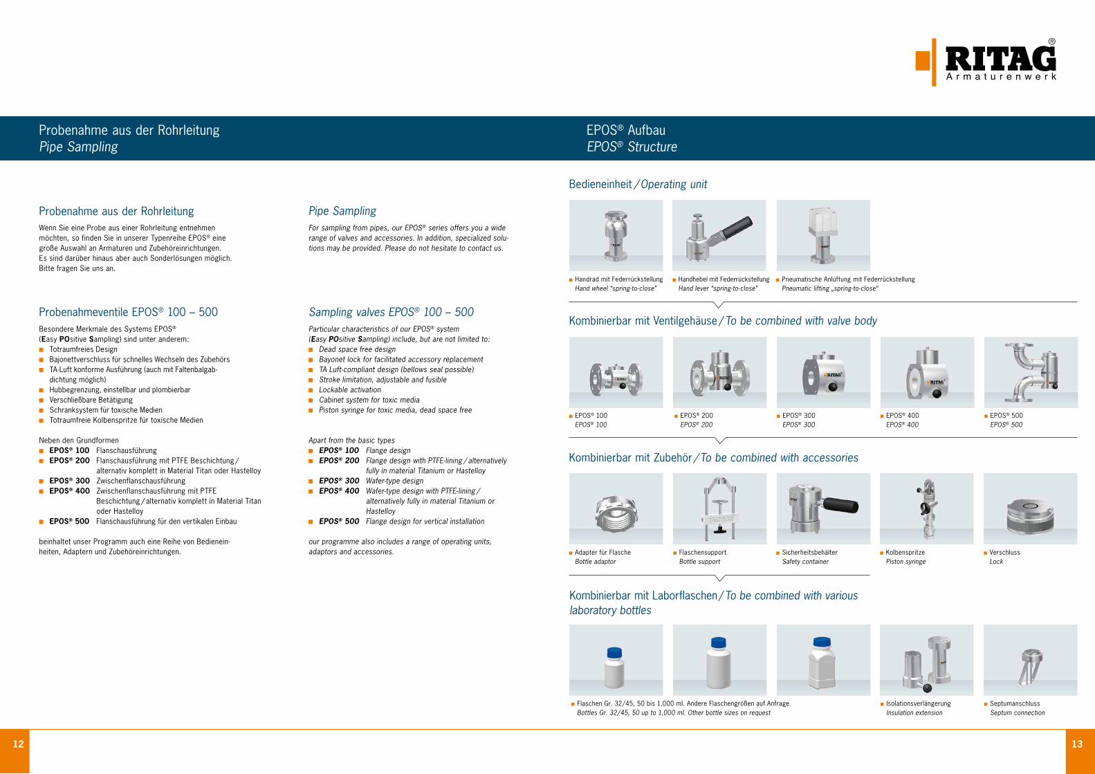
Flaschensupport Bottle support
Adapter für Flasche Bottle adaptor
Flaschen Gr. 32 / 45, 50 bis 1.000 ml. Andere Flaschengrößen auf Anfrage Bottles Gr. 32 / 45, 50 up to 1,000 ml. Other bottle sizes on request
Kombinierbar mit Laborflaschen / To be combined with various laboratory bottles
Probenahme aus der RohrleitungPipe Sampling
Probenahme aus der RohrleitungWenn Sie eine Probe aus einer Rohrleitung entnehmenmöchten, so finden Sie in unserer Typenreihe EPOS® einegroße Auswahl an Armaturen und Zubehöreinrichtungen.Es sind darüber hinaus aber auch Sonderlösungen möglich.Bitte fragen Sie uns an.
Probenahmeventile EPOS® 100 – 500Besondere Merkmale des Systems EPOS® (Easy POsitive Sampling) sind unter anderem: Totraumfreies Design Bajonettverschluss für schnelles Wechseln des Zubehörs TA - Luft konforme Ausführung (auch mit Faltenbalgab-
dichtung möglich) Hubbegrenzung, einstellbar und plombierbar Verschließbare Betätigung Schranksystem für toxische Medien Totraumfreie Kolbenspritze für toxische Medien
Neben den Grundformen EPOS® 100 Flanschausführung EPOS® 200 Flanschausführung mit PTFE Beschichtung /
alternativ komplett in Material Titan oder Hastelloy EPOS® 300 Zwischenflanschausführung EPOS® 400 Zwischenflanschausführung mit PTFE
Beschichtung / alternativ komplett in Material Titan oder Hastelloy
EPOS® 500 Flanschausführung für den vertikalen Einbau
beinhaltet unser Programm auch eine Reihe von Bedienein- heiten, Adaptern und Zubehöreinrichtungen.
Pipe SamplingFor sampling from pipes, our EPOS® series offers you a wide range of valves and accessories. In addition, specialized solu- tions may be provided. Please do not hesitate to contact us.
Sampling valves EPOS® 100 – 500Particular characteristics of our EPOS® system (Easy POsitive Sampling) include, but are not limited to: Dead space free design Bayonet lock for facilitated accessory replacement TA Luft-compliant design (bellows seal possible) Stroke limitation, adjustable and fusible Lockable activation Cabinet system for toxic media Piston syringe for toxic media, dead space free
Apart from the basic types EPOS® 100 Flange design EPOS® 200 Flange design with PTFE-lining / alternatively
fully in material Titanium or Hastelloy EPOS® 300 Wafer-type design EPOS® 400 Wafer-type design with PTFE-lining /
alternatively fully in material Titanium or Hastelloy
EPOS® 500 Flange design for vertical installation
our programme also includes a range of operating units, adaptors and accessories.
Bedieneinheit / Operating unit
Handrad mit Federrückstellung Hand wheel “spring-to-close”
Kombinierbar mit Ventilgehäuse / To be combined with valve body
Isolationsverlängerung Insulation extension
Septumanschluss Septum connection
Handhebel mit Federrückstellung Hand lever “spring-to-close”
Pneumatische Anlüftung mit Federrückstellung Pneumatic lifting „spring-to-close“
EPOS® 100 EPOS® 100
EPOS® 200 EPOS® 200
EPOS® 300 EPOS® 300
EPOS® 400 EPOS® 400
EPOS® 500 EPOS® 500
Kombinierbar mit Zubehör / To be combined with accessories
Kolbenspritze Piston syringe
Verschluss Lock
Sicherheitsbehälter Safety container
EPOS® AufbauEPOS® Structure
14 15
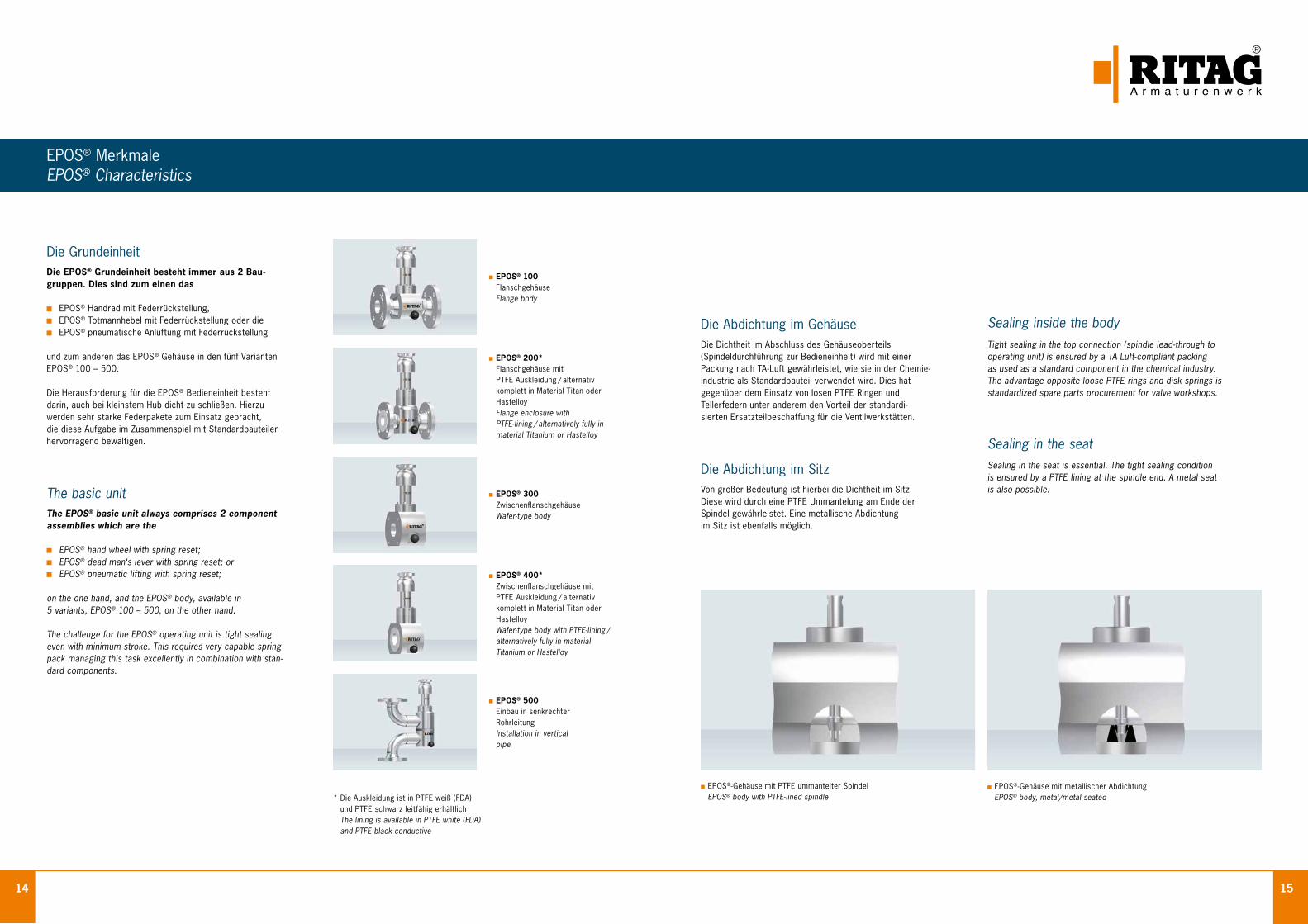
Die Abdichtung im GehäuseDie Dichtheit im Abschluss des Gehäuseoberteils (Spindeldurchführung zur Bedieneinheit) wird mit einer Packung nach TA - Luft gewährleistet, wie sie in der Chemie-Industrie als Standardbauteil verwendet wird. Dies hat gegenüber dem Einsatz von losen PTFE Ringen und Tellerfedern unter anderem den Vorteil der standardi-sierten Ersatzteilbeschaffung für die Ventilwerkstätten.
Die Abdichtung im SitzVon großer Bedeutung ist hierbei die Dichtheit im Sitz. Diese wird durch eine PTFE Ummantelung am Ende der Spindel gewährleistet. Eine metallische Abdichtung im Sitz ist ebenfalls möglich.
EPOS® MerkmaleEPOS® Characteristics
EPOS® 100 Flanschgehäuse Flange body
EPOS® 200* Flanschgehäuse mit PTFE Auskleidung / alternativ komplett in Material Titan oder Hastelloy Flange enclosure with PTFE-lining / alternatively fully in material Titanium or Hastelloy
EPOS® 300 Zwischenflanschgehäuse Wafer-type body
EPOS® 400* Zwischenflanschgehäuse mit PTFE Auskleidung / alternativ komplett in Material Titan oder Hastelloy Wafer-type body with PTFE-lining / alternatively fully in material Titanium or Hastelloy
EPOS® 500 Einbau in senkrechter Rohrleitung Installation in vertical pipe
Die GrundeinheitDie EPOS® Grundeinheit besteht immer aus 2 Bau- gruppen. Dies sind zum einen das
EPOS® Handrad mit Federrück stellung, EPOS® Totmannhebel mit Federrückstellung oder die EPOS® pneumatische Anlüftung mit Federrückstellung
und zum anderen das EPOS® Gehäuse in den fünf Varianten EPOS® 100 – 500. Die Herausforderung für die EPOS® Bedieneinheit besteht darin, auch bei kleinstem Hub dicht zu schließen. Hierzu werden sehr starke Federpakete zum Einsatz gebracht, die diese Aufgabe im Zusammenspiel mit Standardbauteilen hervorragend bewältigen.
The basic unitThe EPOS® basic unit always comprises 2 component assemblies which are the
EPOS® hand wheel with spring reset; EPOS® dead man‘s lever with spring reset; or EPOS® pneumatic lifting with spring reset;
on the one hand, and the EPOS® body, available in 5 variants, EPOS® 100 – 500, on the other hand. The challenge for the EPOS® operating unit is tight sealing even with minimum stroke. This requires very capable spring pack managing this task excellently in combination with stan-dard components.
Sealing inside the body Tight sealing in the top connection (spindle lead-through to operating unit) is ensured by a TA Luft-compliant packing as used as a standard component in the chemical industry. The advantage opposite loose PTFE rings and disk springs is standardized spare parts procurement for valve workshops.
Sealing in the seat Sealing in the seat is essential. The tight sealing condition is ensured by a PTFE lining at the spindle end. A metal seat is also possible.
EPOS®-Gehäuse mit PTFE ummantelter Spindel EPOS® body with PTFE-lined spindle
EPOS®-Gehäuse mit metallischer Abdichtung EPOS® body, metal/metal seated* Die Auskleidung ist in PTFE weiß (FDA)
und PTFE schwarz leitfähig erhältlich The lining is available in PTFE white (FDA) and PTFE black conductive
16 17
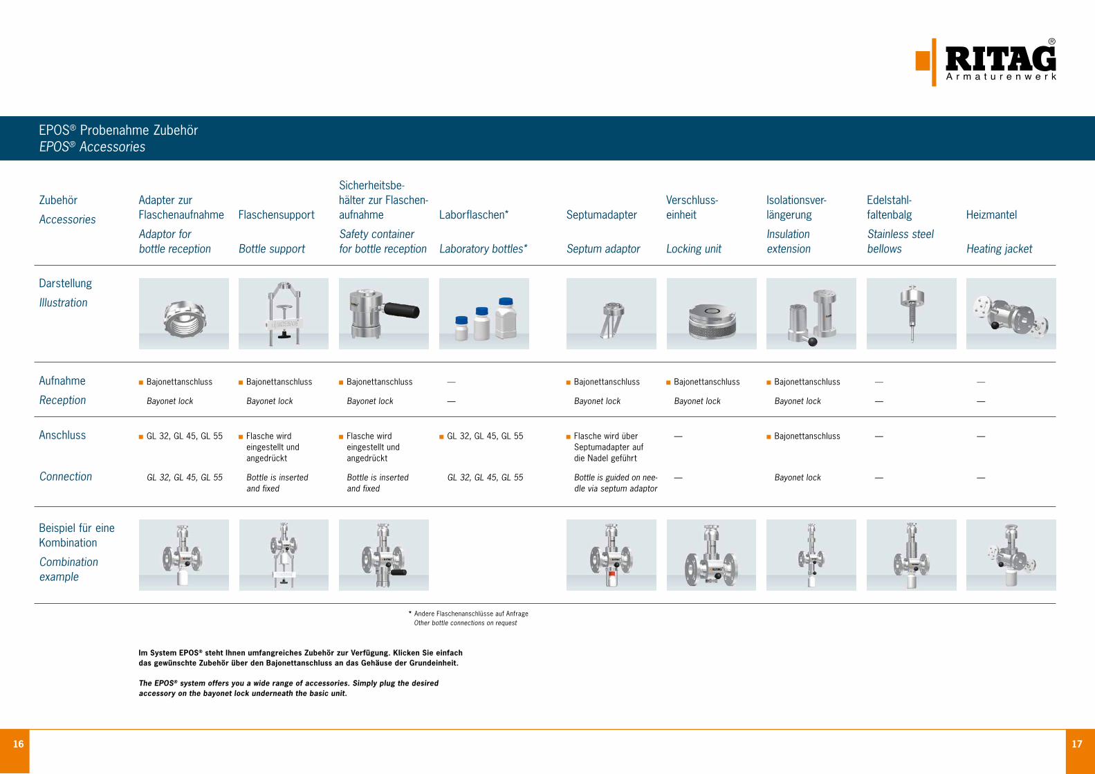
EPOS® Probenahme ZubehörEPOS® Accessories
Zubehör
Accessories
Darstellung
Illustration
Aufnahme Bajonettanschluss Bajonettanschluss Bajonettanschluss — Bajonettanschluss Bajonettanschluss Bajonettanschluss — —
Reception Bayonet lock Bayonet lock Bayonet lock — Bayonet lock Bayonet lock Bayonet lock — —
Anschluss GL 32, GL 45, GL 55 Flasche wird Flasche wird GL 32, GL 45, GL 55 Flasche wird über — Bajonettanschluss — — eingestellt und eingestellt und Septumadapter auf angedrückt angedrückt die Nadel geführt
Connection GL 32, GL 45, GL 55 Bottle is inserted Bottle is inserted GL 32, GL 45, GL 55 Bottle is guided on nee- — Bayonet lock — — and fixed and fixed dle via septum adaptor
Beispiel für eine Kombination
Combination example
Sicherheitsbe- Adapter zur hälter zur Flaschen- Verschluss- Isolationsver- Edelstahl- Flaschenaufnahme Flaschensupport aufnahme Laborflaschen* Septumadapter einheit längerung faltenbalg Heizmantel Adaptor for Safety container Insulation Stainless steel bottle reception Bottle support for bottle reception Laboratory bottles* Septum adaptor Locking unit extension bellows Heating jacket
Im System EPOS® steht Ihnen umfangreiches Zubehör zur Verfügung. Klicken Sie einfach das gewünschte Zubehör über den Bajonettanschluss an das Gehäuse der Grundeinheit. The EPOS® system offers you a wide range of accessories. Simply plug the desired accessory on the bayonet lock underneath the basic unit.
* Andere Flaschenanschlüsse auf Anfrage Other bottle connections on request
18 19
EPOS® SchranksystemEPOS® Cabinet System
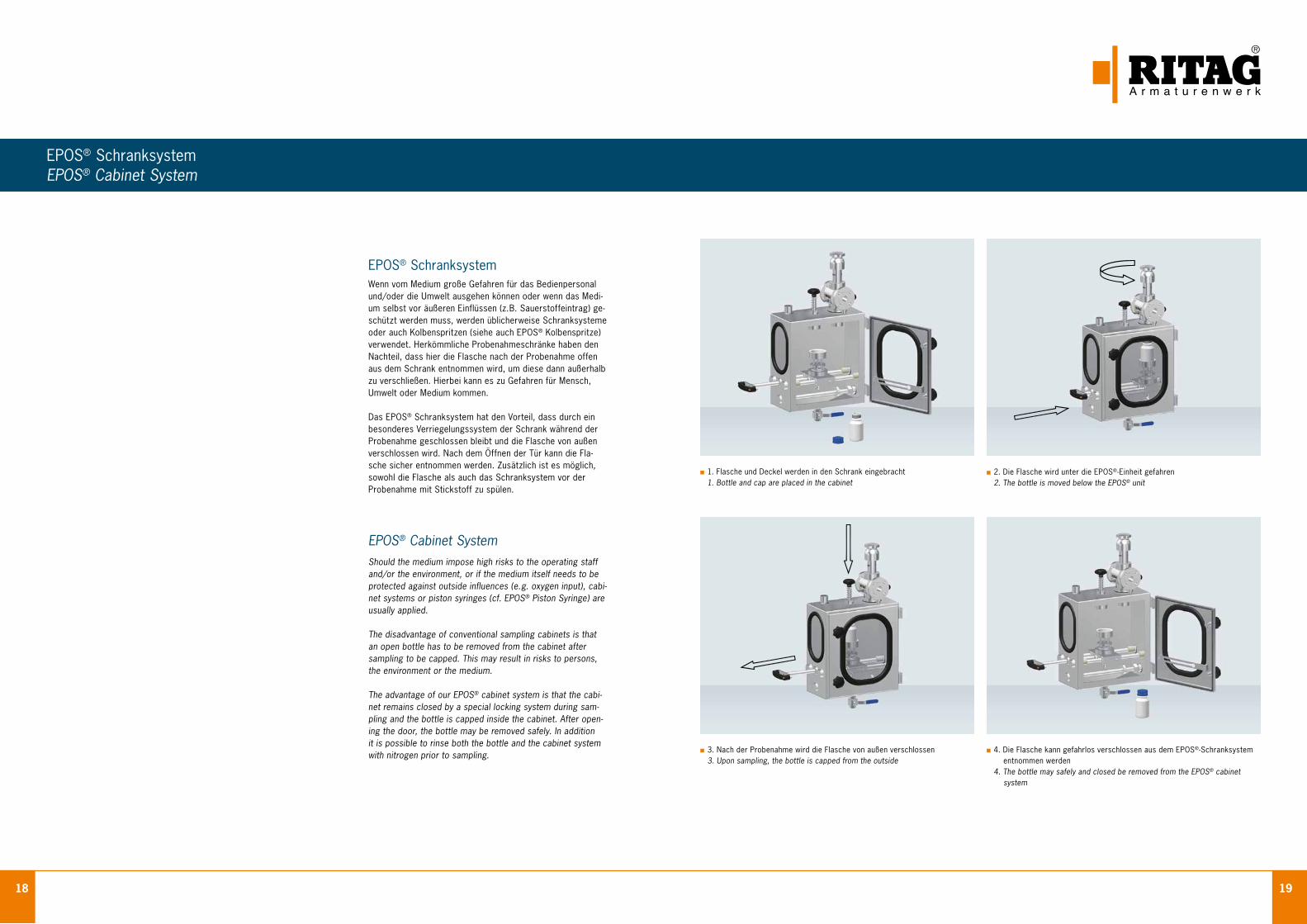
EPOS® SchranksystemWenn vom Medium große Gefahren für das Bedienpersonal und/oder die Umwelt ausgehen können oder wenn das Medi-um selbst vor äußeren Einflüssen (z. B. Sauerstoffeintrag) ge-schützt werden muss, werden üblicherweise Schranksysteme oder auch Kolbenspritzen (siehe auch EPOS® Kolbenspritze) verwendet. Herkömmliche Probenahmeschränke haben den Nachteil, dass hier die Flasche nach der Probenahme offen aus dem Schrank entnommen wird, um diese dann außerhalb zu verschließen. Hierbei kann es zu Gefahren für Mensch, Umwelt oder Medium kommen. Das EPOS® Schranksystem hat den Vorteil, dass durch ein besonderes Verriegelungssystem der Schrank während der Probenahme geschlossen bleibt und die Flasche von außen verschlossen wird. Nach dem Öffnen der Tür kann die Fla-sche sicher entnommen werden. Zusätzlich ist es möglich, sowohl die Flasche als auch das Schranksystem vor der Probenahme mit Stickstoff zu spülen.
EPOS® Cabinet SystemShould the medium impose high risks to the operating staff and/or the environment, or if the medium itself needs to be protected against outside influences (e. g. oxygen input), cabi-net systems or piston syringes (cf. EPOS® Piston Syringe) are usually applied.
The disadvantage of conventional sampling cabinets is that an open bottle has to be removed from the cabinet after sampling to be capped. This may result in risks to persons, the environment or the medium. The advantage of our EPOS® cabinet system is that the cabi-net remains closed by a special locking system during sam-pling and the bottle is capped inside the cabinet. After open-ing the door, the bottle may be removed safely. In addition it is possible to rinse both the bottle and the cabinet system with nitrogen prior to sampling.
2. Die Flasche wird unter die EPOS®-Einheit gefahren 2. The bottle is moved below the EPOS® unit
1. Flasche und Deckel werden in den Schrank eingebracht 1. Bottle and cap are placed in the cabinet
4. Die Flasche kann gefahrlos verschlossen aus dem EPOS®-Schranksystem entnommen werden
4. The bottle may safely and closed be removed from the EPOS® cabinet system
3. Nach der Probenahme wird die Flasche von außen verschlossen 3. Upon sampling, the bottle is capped from the outside
20 21
EPOS® KolbenspritzeEPOS® Piston Syringe
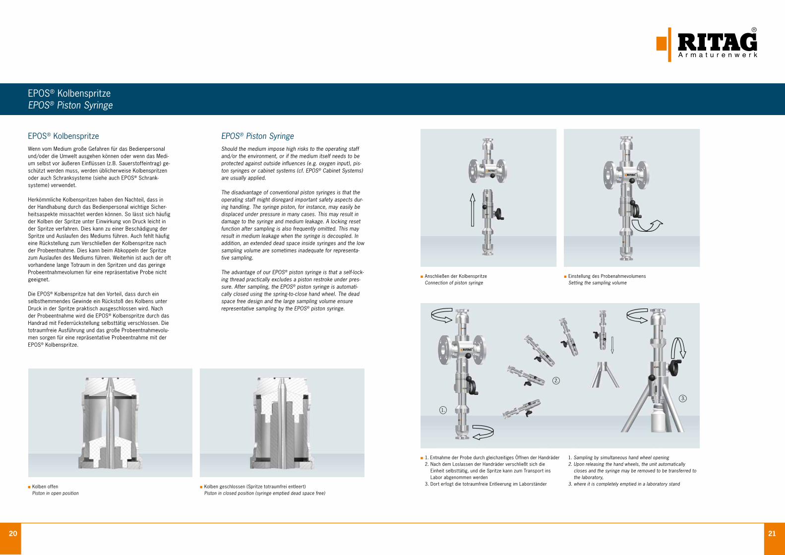
EPOS® KolbenspritzeWenn vom Medium große Gefahren für das Bedienpersonal und/oder die Umwelt ausgehen können oder wenn das Medi-um selbst vor äußeren Einflüssen (z.B. Sauerstoffeintrag) ge-schützt werden muss, werden üblicherweise Kolbenspritzen oder auch Schranksysteme (siehe auch EPOS® Schrank- systeme) verwendet. Herkömmliche Kolbenspritzen haben den Nachteil, dass in der Handhabung durch das Bedienpersonal wichtige Sicher-heitsaspekte missachtet werden können. So lässt sich häufig der Kolben der Spritze unter Einwirkung von Druck leicht in der Spritze verfahren. Dies kann zu einer Beschädigung der Spritze und Auslaufen des Mediums führen. Auch fehlt häufig eine Rückstellung zum Verschließen der Kolbenspritze nach der Probeentnahme. Dies kann beim Abkoppeln der Spritze zum Auslaufen des Mediums führen. Weiterhin ist auch der oft vorhandene lange Totraum in den Spritzen und das geringe Probeentnahmevolumen für eine repräsentative Probe nicht geeignet. Die EPOS® Kolbenspritze hat den Vorteil, dass durch ein selbsthemmendes Gewinde ein Rückstoß des Kolbens unter Druck in der Spritze praktisch ausgeschlossen wird. Nach der Probeentnahme wird die EPOS® Kolbenspritze durch das Handrad mit Federrückstellung selbsttätig verschlossen. Die totraumfreie Ausführung und das große Probeentnahmevolu-men sorgen für eine repräsentative Probeentnahme mit der EPOS® Kolbenspritze.
EPOS® Piston SyringeShould the medium impose high risks to the operating staff and/or the environment, or if the medium itself needs to be protected against outside influences (e.g. oxygen input), pis-ton syringes or cabinet systems (cf. EPOS® Cabinet Systems) are usually applied.
The disadvantage of conventional piston syringes is that the operating staff might disregard important safety aspects dur-ing handling. The syringe piston, for instance, may easily be displaced under pressure in many cases. This may result in damage to the syringe and medium leakage. A locking reset function after sampling is also frequently omitted. This may result in medium leakage when the syringe is decoupled. In addition, an extended dead space inside syringes and the low sampling volume are sometimes inadequate for representa-tive sampling. The advantage of our EPOS® piston syringe is that a self-lock-ing thread practically excludes a piston restroke under pres-sure. After sampling, the EPOS® piston syringe is automati-cally closed using the spring-to-close hand wheel. The dead space free design and the large sampling volume ensure representative sampling by the EPOS® piston syringe.
Anschließen der Kolbenspritze Connection of piston syringe
Einstellung des Probenahmevolumens Setting the sampling volume
1. Entnahme der Probe durch gleichzeitiges Öffnen der Handräder 2. Nach dem Loslassen der Handräder verschließt sich die Einheit selbsttätig, und die Spritze kann zum Transport ins
Labor abgenommen werden 3. Dort erfogt die totraumfreie Entleerung im Laborständer
Kolben offen
Piston in open position Kolben geschlossen (Spritze totraumfrei entleert)
Piston in closed position (syringe emptied dead space free)
1.
2.
3.
1. Sampling by simultaneous hand wheel opening 2. Upon releasing the hand wheels, the unit automatically closes and the syringe may be removed to be transferred to the laboratory, 3. where it is completely emptied in a laboratory stand
22 23
EPOS® KombinationenEPOS® Combinations
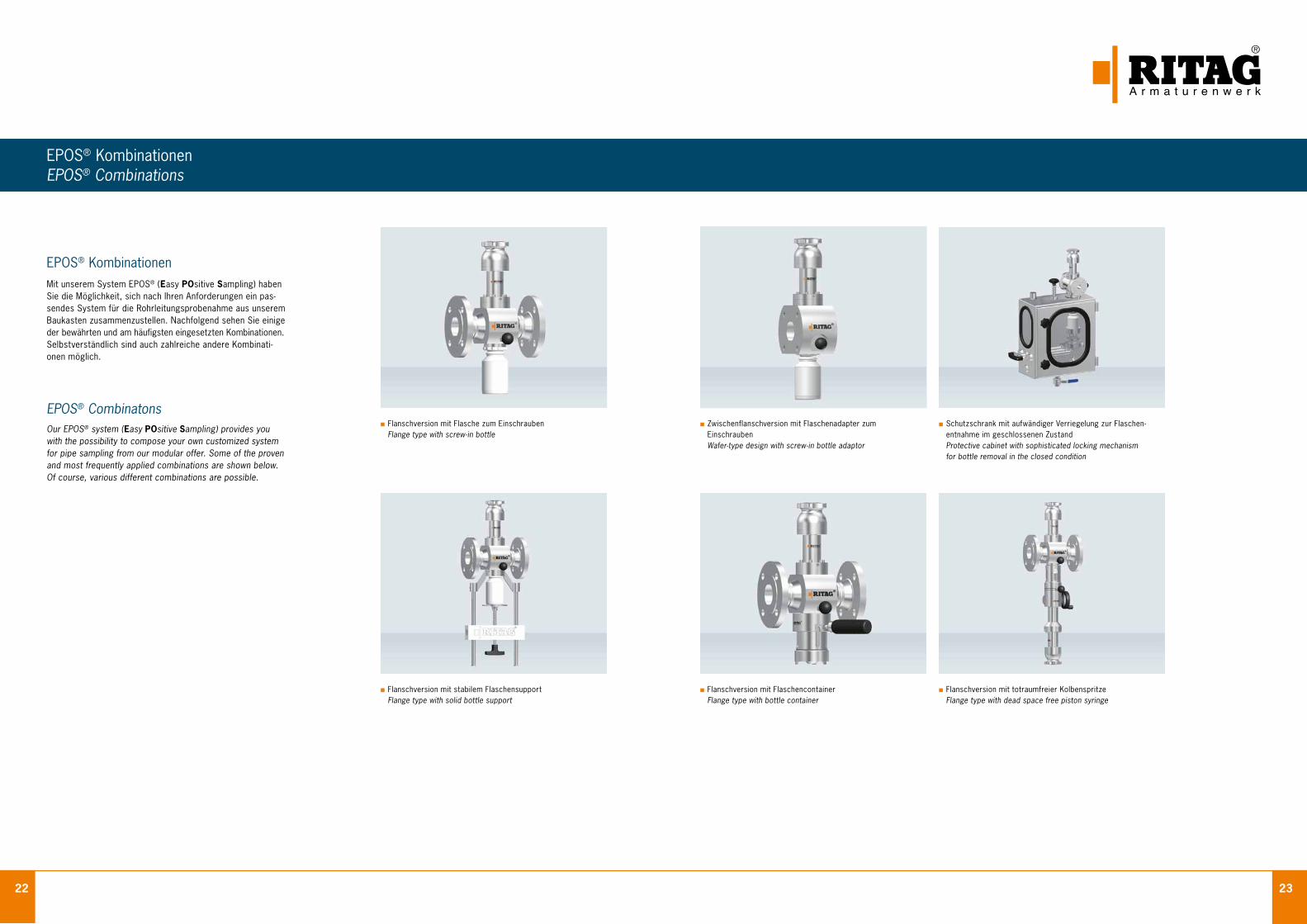
EPOS® KombinationenMit unserem System EPOS® (Easy POsitive Samp ling) haben Sie die Möglichkeit, sich nach Ihren Anforderungen ein pas-sendes System für die Rohrleitungsprobenahme aus unserem Baukasten zusammenzustellen. Nachfolgend sehen Sie einige der bewährten und am häufigsten eingesetzten Kombinationen. Selbstverständlich sind auch zahlreiche andere Kombinati-onen möglich.
EPOS® CombinatonsOur EPOS® system (Easy POsitive Sampling) provides you with the possibility to compose your own customized system for pipe sampling from our modular offer. Some of the proven and most frequently applied combinations are shown below. Of course, various different combinations are possible.
Flanschversion mit Flaschencontainer Flange type with bottle container
Flanschversion mit Flasche zum Einschrauben Flange type with screw-in bottle
Flanschversion mit totraumfreier Kolbenspritze Flange type with dead space free piston syringe
Zwischenflanschversion mit Flaschenadapter zum Einschrauben
Wafer-type design with screw-in bottle adaptor
Flanschversion mit stabilem Flaschensupport Flange type with solid bottle support
Schutzschrank mit aufwändiger Verriegelung zur Flaschen- entnahme im geschlossenen Zustand
Protective cabinet with sophisticated locking mechanism for bottle removal in the closed condition
24 25
Werkstoffe und DichtungenMaterials and Seat Rings
Prüfungen und ZertifikateTestings and Certificates
ISO 9001:2000 Zertifiziert das Qualitäts-Management-System
nach DIN EN ISO 9001 für Entwicklung, Kons-truktion, Herstellung und Prüfung von Armaturen
ISO 9001:2000 Certifies the quality management system accor-ding to DIN EN ISO 9001 for the development, construction, production and testing of check valves
GOST-Zertifikat Bestätigt, dass die benannten Arma turen den
russischen Sicherheits- und Bauvorschriften entsprechen und nach Russland eingeführt wer-den dürfen
GOST-Certificate Confirms that named check valves comply with Russian safety and construction requirements and may be imported to Russia
Type Test Zertifikat (China) Zertifiziert, dass RITAG Produkte gemäß der chinesischen Norm TSG D7002 - 2006 (Pressure
Piping Components Type Test Regulation) getestet und zugelassen sind.
Type Test Certificate (China) Certifies that RITAG products have been tested
and approved in accordance to Chinese Standard TSG D7002 - 2006 (Pressure Piping Components Type Test Regulation).
DGRL 97/23/EG Modul H Bestätigt, dass das Qualitätssicherungssystem
dem Modul H der Druckgeräterichtlinie 97/23/EG entspricht
PED 97/23/EC Module H Confirms that the quality assurance system complies with Module H of Pressure Equipment Directive 97/23/EC
AD 2000-HP0 Zertifiziert, dass RITAG als Hersteller nach
AD 2000-HP0 überprüft und anerkannt ist
AD 2000-HP0 Certifies that RITAG has been tested and acknowledged as a manufacturer according to AD 2000-HPO
DIN EN 729-2 Zertifiziert, dass RITAG als Schweißbetrieb
nach DIN EN 729-2 überprüft und anerkannt ist
DIN EN 729-2 Certifies that RITAG has been tested and acknowledged as a welding company according to DIN EN 729-2
Werkstoff-Nr. Werkstoffbezeichnung DIN EN-Norm ASTM Werkstoff UNS-Nummer HandelsnameMaterial-No. Material Name DIN EN Standard ASTM Material UNS No. Trade Nameferritischer Stahl ferritic steel1.0425 P265GH 10273 A515 Grade60 1.0460 P250GH 10273 A105 1.0577 S355J2+N 10025 1.5415 16Mo3 10273 A182 F1 K12822 1.7335 13CrMo4-5 10273 A182 F12 Class 1 K11562 1.7362 X12CrMo5 10273 A182 F5 K41545 1.7380 10CrMo9-10 10273 A182 F22 K21590
A350 LF2martensitisch nichtrostender Stahl martensitic stainless steel 1.4006 X12Cr13 10272 AISI410 S41000 1.4104 X14CrMoS17 10088-3 AISI 430 S43020 1.4122 X39CrMo17-1 10088-3 1.4313 X3CrNiMo13-4 10272 austenitischer Stahl austenitic stainless steel 1.4301 X5CrNi18-10 10272 A182 F304 S30400 1.4305 X8CrNiS18-9 10272 AISI 303 1.4307 X2CrNi18-9 10272 A182 F304L S30403 1.4401 X5CrNiMo17-12-2 10272 A182 F316 S31600 1.4404 X2CrNiMo17-12-2 10272 A182 F316L S31603 1.4429 X2CrNiMoN17-13-3 10272 1.4435 X2CrNiMo18-14-3 10272 A182 F316L S31603 Basler Norm1.4439 X2CrNiMoN17-13-5 10272 A182 F317LN S31703 1.4529 X1CrNiMoCuN25-20-7 10272 N08926 254SMO 1.4539 X1NiCrMoCu25-20-5 10272 A182 F904L N08904 Uranus B61.4541 X6CrNiTi18-10 10272 A182 F321 S32100 1.4550 X6CrNiNb18-10 10272 A182 F347 S34700 1.4571 X6CrNiMoTi17-12-2 10272 austenitisch, ferritischer Stahl (Duplex,Superduplex) austenitic, ferritic stainless steel (duplex, superduplex)1.4410 X2CrNiMoN25-7-4 10272 A182 F53 S32750 Superduplex1.4462 X2CrNiMoN22-5-3 10272 A182 F51 S31803 SAF2205 1.4501 X2CrNiMoCuWN25-7-4 10272 A182 F55 S32760 Superduplex hochkorrosionsbeständige Werkstoffe high corrosion resistant alloys2.0872 CuNi 10 Fe C70600 Cunifer 102.0882 CuNi 30 Fe C71500 Cunifer 302.4066 Ni 99,2 DIN 17751 N02200 Nickel 2002.4068 LCNi 99 VDTÜV 345 N02201 Nickel 201 2.4360 NiCu 30Fe VDTÜV 263 N04400 Monel 4002.4602 NiCr 21 Mo 14 W VDTÜV 479 N06022 Hastelloy C22 2.4605 NiCr 23 Mo 16 Al VDTÜV 505 N06059 Alloy 59 2.4610 NiMo 16 Cr 16 TI VDTÜV 424 N06455 Hastelloy C42.4617 NiMo 28 VDTÜV 436 N10665 Hastelloy B22.4819 NiMo 16Cr 13 W VDTÜV 400 N10276 Hastelloy 2762.4851 NiCr 60 23 Al DIN 17742 N06601 Inconel 6012.4856 NiCr 22 Mo 9 Nb DIN 17751 N06625 Inconel 6252.4858 NiCr 21 Mo VDTÜV 432 N08825 Incoloy 825
Kurzzeichen Chemische Bezeichnung Handelsname Temperatur BeständigkeitAbbreviation Chemical name Trade name Temperature Resistant toElastomere ElastomerFPM Fluor-Kautschuk Viton ® - 25 °C bis 200 °C Ozon, Sauerstoff, Erdgas, Kraftstoffe, Mineralöle,FKM Hydrauliköl, organische LösungsmittelFPM Fluorocarbon rubber Viton ® - 25 °C to 200 °C Ozone, oxygen, natural gas, fuels, mineral oils,FKM hydraulic oil, organic solventsKalrez ® Perfluorelastomer Kalrez ® bis 315 °C Nahezu alle organischen und anorganischen ChemikalienKalrez ® Perfluorelastomere Kalrez ® up to 315 °C Almost all organic and inorganic chemicalsFluor-Kunststoffe Fluoric plasticsPTFE Polytetrafluorethylen Teflon ® / Hostflon ® - 200 °C bis 250 °C Nahezu alle organischen und anorganischen ChemikalienPTFE Polytetrafluorethylene Teflon ® / Hostflon ® - 200 °C to 250 °C Almost all organic and inorganic chemicals
Werkstoffe / Materials
Dichtungen / Seat Rings
ISO 14001:2004 Mit diesem Zertifikat unterstreicht RITAG das
hohe Engagement für die Einhaltung der Umwelt-schutznormen.
ISO 14001:2004
This certificate underlines the strong commitment of RITAG for compliance with environmental standards.
OHSAS 18001:2007 Bescheinigt, dass das RITAG Managementsystem
zielgerichtet die Arbeitschutznormen erfüllt.
OHSAS 18001:2007 Certifies that the RITAG management system
meets the safety standards.

26 27
Abnahmen Inspections
StandardprüfumfangWerkstoffprüfungenDie Prüfungen werden als Mindestprüfumfang gemäß der fürden jeweiligen Werkstoff gültigen Lieferbedingung (Norm)ausgeführt. Dies gilt für Armaturen mit den BescheinigungenEN 10204 / 2.2 und 3.1.
Schmelzanalyse Wärmebehandlung Zugversuch bei Raumtemperatur Kerbschlagbiegeversuch bei Raumtemperatur Werkstoffverwechslungsprüfung bei legierten Werkstoffen IK-Beständigkeit bei austenitischen Werkstoffen
BauprüfungenAn den Standardarmaturen werden Bauprüfungen nachDIN 3230 Teil 3, EN 12266-1, -2 durchgeführt und in einerBescheinigung EN 10204/2.2 bzw. 3.1 dokumentiert:
Prüfung der Bestellangaben - AA Prüfung der Kennzeichnung - AC Besichtigung, Maßprüfung - AD, AE, AP Festigkeitsprüfung des Gehäuses - BA, BQ / P10 Dichtheitsprüfung (Gussgehäuse) - BE / P11 Dichtheitsprüfung des Abschlusses - BN oder BO / P12 Funktionsprüfung - AG / F20
Inhalt der EN 10204 - BescheinigungenWerkszeugnis 2.2 1)
Bescheinigung, ausgestellt auf der Grundlage von nichtspe-zifischen Prüfungen, d. h. die geprüften Erzeugnisse müssennicht aus der Lieferung stammen.
Abnahmeprüfzeugnis 3.1 1)
Bescheinigung, ausgestellt auf der Grundlage von Prüfun-gen, die in der Bestellung genannt sind und/oder nach amt-lichen Vorschriften und den zugehörigen technischen Regelndurchgeführt werden. Die Prüfungen müssen an den Armatu-ren oder an Armaturen der Prüfeinheit, von der die Lieferungein Teil ist, durchgeführt worden sein und vom unabhängigenAbnahmebeauftragten des Herstellers bestätigt werden.Im standardisierten Abnahmeprüfzeugnis wird die in Abs. 1genannte Bauprüfung mit einer Auflistung der zugehörigenWerkstoffbescheinigungen für Armaturengehäuse aufgeführt.
Abnahmeprüfzeugnis 3.2 1)
Bescheinigung, ausgestellt auf der Grundlage von in der Be-stellung genannten amtlichen Vorschriften und den zugehö-rigen Technischen Regeln, durch einen in diesen Vorschriftengenannten Sachverständigen. Die Prüfungen sind an dengelieferten Armaturen durchgeführt worden. Bestätigung derPrüfungen durch den unabhängigen Abnahmebeauftragtendes Herstellers und dem vom Besteller bestimmten Abnahme-beauftragten.
Weitere Prüfmöglichkeiten Farbeindringprüfung Magnetpulverprüfung Ultraschallprüfung Durchstrahlungsprüfung Material-Identifikation (PMI)
1) Bezeichnungen gemäß EN 10204, aktuelle Ausgabe
Die Abnahmeanforderungen entsprechen dem für den jeweiligen Werkstoff beschriebenen Mindestprüfumfang der Norm.Alle Anforderungen sind bei der Bestellung anzugeben. Nach erfolgter Lieferung können aufgrund des QM-Systems nurnoch Werkszeugnisse EN 10204 / 2.2 für die Bauprüfung ausgestellt werden.
Standard Scope of TestingMaterial TestingThese testings are carried out in accordance to the minimumscope of testing that is required by the standard applicablefor the relevant material. It applys for all valves with certifica-tions acc. EN 10204/2.2 respectively 3.1.
Analysis Heat treatment Tensile test Impact test Positive material identification test (PMI) Corrosion test (for stainless steel)
InspectionsOn standard valves inspections in acc. to DIN 3230 part 3,EN 12266-1, -2 are carried out which are documented in acertification acc. EN 10204/2.2 resp. 3.1.
Checking of purchase order details - AA Checking of marking - AC Visual inspection, dimensional check - AD, AE, AP Shell test - BA, BQ / P10 Leakage test (cast bodies) - BE / P11 Seat leakage test - BN or BO / P12 Performance test - AG / F20
Content of Certificates in acc. to EN 10204Certification acc. 2.2 1)
This certification is issued on the basis of non-specific testing,i . e. the tested products must not originate from the lot.
Certification acc. 3.1 1)
This certification is issued on the basis of those testings whichare required in the purchase order and/or which are carriedout in accordance to any legal regulations incl. the applicabletechnical rules. These testings have to be carried out on thevalve itself or on valves of the probe unit of which the deliveryis a part of. In addition it is proved by an independent manu-facturer’s inspector. The inspection mentioned in paragraph 1is indicated in the standardized certification incl. a listing ofmaterial certificates applicable for the valve bodies.
Certification acc. 3.2 1)
This certification is issued on the basis of the legal regulationsas well as the technical rules required in the purchase orderby an official inspector mentioned in these regulations. Theinspections are executed on the valves supplied. Confirmationof inspections by independent manufacturer’s inspector aswell as the inspector determined by the customer.
Additional Testings Liquid penetrant test Magnetic particle inspection Ultrasonic examination X-Ray Positive material identification (PMI)
1) Description acc. to EN 10204, current edition
All inspections are carried out in accordance to the minimum scope of testing that is required by the standard applicablefor the relevant material. All testing requirements need to be stated in the purchase order by the customer. After deliveryhas been effected it is only possible within the framework of the QM-system to issue a certification in acc. to EN 10204/2.2for inspection only (i. e. excluding material testing).
28 29
Bodenventile
Tank Bottom Valves
Zwischenflansch- Rückschlagarmaturen
Wafer Type Check Valves
BAS mit Heizmantel und doppelt- wirkendem Antrieb
BAS with heating jacket and double acting actuator
BA mit einfachwirkendem Antrieb BA with single acting actuator
Unser weiteres ProgrammEntire Product Range
Sonderausführung Tankentleerungsventil (durch den Tank)
Special Design Valve for tank draining (through the tank)
ZRK Zwischenflansch-Rückschlagklappe ZRK Wafer Type Swing Check Valve
SR Zwischenflansch-Rückschlagventil SR Wafer Type Check Valve
ZRD Zwischenflansch-Doppelrück- schlagkappe ZRD Wafer Type Duo Check Valve
HYPOS® 100 Zwischenflansch-Rückschlagventil mit besonderen Einbauteilen und EHEDG Zulassung HYPOS® 100 Wafer Type Check Valve with specific internals and EHEDG approval
SR 93 Zwischenflansch-Rückschlagventil SR 93 Wafer Type Check Valve
Clean Service
Clean Service
Weltweite VerfügbarkeitUnser before - und after sales Service ist rundum vorbildlich. Hier überzeugen wir durch unsere Professionalität. Angefangen von der Durchführung von Problemanalysen und Wartungsmaß- nahmen bis hin zur Vor - Ort - Betreuung und natürlich der prozessbezogenen Anpassung unserer Produkte sowie deren entsprechende Ersatzteilbevorratung. All das macht uns hoch flexibel und sichert den reibungslosen Ablauf in Ihrem Unternehmen.
Wo auch immer Sie RITAG - Armaturen einsetzen möchten, stehen Ihnen ausgesuchte und speziell geschulte Partner zur Verfügung. Zu ihren Aufgaben zählt nicht nur die Lagerhaltung, sondern auch Ihre kompetente Vor - Ort - Betreuung. So haben Sie den Vorteil des schnellen Zugriffs auf unsere Produkte und auf die entsprechende Beratung hoch motivierter Mitarbeiter, die mit den geschäftlichen Gepflogenheiten des Landes bestens vertraut sind.
Present WorldwideOur before and after sales service is exemplary in all aspects. Our professionalism will convince you. It all begins with conducting problem analysis and continues with the on-site customer advisory service and proceeds further with the process-related adaptation of our products as well as spare parts stockpiling. All of this makes us highly flexible and secures the smooth running of your company process.
Wherever you want to utilize RITAG valves worldwide, there is a selected and fully trained partner available to you. Their responsibilities cover not only the stock, but your competent on-site customer advisory service as well. Hence the advantage to you is not only the quick access to our products, but also the competent advice coming from highly motivated personnel who are extremely familiar with the business practices of the country and industry in question.
ServiceService
Vertretungen Representatives Deutschland Germany
Ägypten Egypt Australien Australia Bahrain Bahrain Belgien Belgium Brasilien Brazil Chile Chile Dänemark Denmark Finnland Finland Frankreich France Großbritannien Great Britain Hongkong Hong Kong Indien India Indonesien Indonesia Iran Iran Irland Ireland Italien Italy Japan Japan Katar Qatar Malaysia Malaysia Mexiko Mexico Niederlande The Netherlands Nigeria Nigeria Norwegen Norway Österreich Austria Polen Poland Portugal Portugal Russland Russia Saudi-Arabien Saudi Arabia Schweden Sweden Schweiz Switzerland Singapur Singapore Slowakei Slovakia Spanien Spain Südafrika South Africa Südkorea South Korea Taiwan Taiwan Thailand Thailand Tschechien Czechia Ungarn Hungary USA USA VAE UAE VR China PR China
RITAGRitterhuder Armaturen GmbH & Co.Armaturenwerk KGSachsenring 3027711 Osterholz-ScharmbeckGemany
Phone +49 (0) 47 95 - 5 50 42 - 0Fax +49 (0) 47 95 - 5 50 42 - 850E-mail [email protected] www.ritag.com
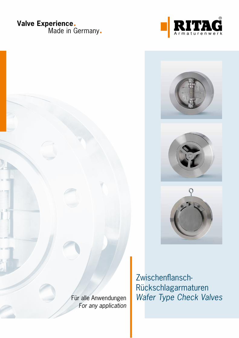
Valve Experience. Made in Germany.
Für alle AnwendungenFor any application
Zwischenflansch- RückschlagarmaturenWafer Type Check Valves

3
InhaltsverzeichnisContents
Rückschlagarmaturen Check Valves
Zwischenflansch-Doppelrückschlagklappen API Wafer Type Dual Plate Check Valve API 4
Zwischenflansch-Doppelrückschlagklappen DIN Wafer Type Dual Plate Check Valve DIN 6
Anschlussvarianten Connection Versions 8
Baulängen F / F Dimensions 9
Armaturenprüfstand Check Valve Test Facility 10
Zwischenflansch-Rückschlagventile Wafer Type Lift Check Valve 12
Zwischenflansch-Rückschlagklappen Wafer Type Swing Check Valve 16
Einbau Installation 18
Auslegung Dimensioning 19
Druckverlustdiagramme Pressure Drop Diagrams 20
Dichtungen Seat Rings 24
Werkstoffe Materials 25
Beispielhafte Prüfungen und Zertifikate Exemplary Testings and Certificates 26
Abnahmen Inspections 28
Unser weiteres Programm Entire Product Range 30
Weltweite Verfügbarkeit Present Worldwide 31
Technische Änderungen vorbehalten 07 / 2014Technical modifications reserved 07 / 2014
Made in GermanyJahrzehntelange Erfahrungen und weltweite Referenzen für den Einsatz unserer Armaturen unter den extremen Einsatzbedingungen von Chemie, Pharma, Raffinerien und Anlagenbau bestätigen immer wieder die Leistungsfähigkeit unseres Unternehmens. Als ein weltweit führender Spezialist für die Planung, Konstruktion und Fertigung von Rückschlagarmaturen, Bodenventilen und Probe- nahmeventilen verbindet RITAG Produkte und Service zu maximalem Kundennutzen.
Prozesssicherheit durch erstklassiges Engineering. Flexibel und schnell in der Umsetzung Ihrer Wünsche und Anforderungen. Und nicht zuletzt: Höchste Verfügbarkeit Ihrer Anlagen und Systeme durch ein weltumspannendes Netz von Servicepartnern. RITAG Serienarmaturen sowie Sonder- ausführungen sind in allen prozesserforderlichen Nennweiten, Druckstufen und Werkstoffen liefer- bar. Unsere Ingenieure sorgen für eine Verwendbarkeit der RITAG Produkte nach allen internatio- nalen Normen und Vorschriften.
Made in GermanyDecades of experience and worldwide project references for the use of our non-return valves under the extreme operating conditions of the chemical and pharmaceutical industries, refineries and plant construction confirm our company’s high performance time and time again. As a world- leading specialist in the planning, design and manufacturing of check valves, bottom valves and sampling valves, RITAG focuses its products and service on achieving maximum customer benefit.
Process reliability through first-class engineering. Flexible and fast in realising your specifications and requirements. And last but not least: Maximum availability of your plant and systems by means of a global network of service partners. RITAG standard non-return valves and special designs are available in all nominal dimensions, pressure ratings and materials required for specific pro- cesses. Our engineers ensure that RITAG products operate in accordance with all international standards and regulations.
QualitätQuality
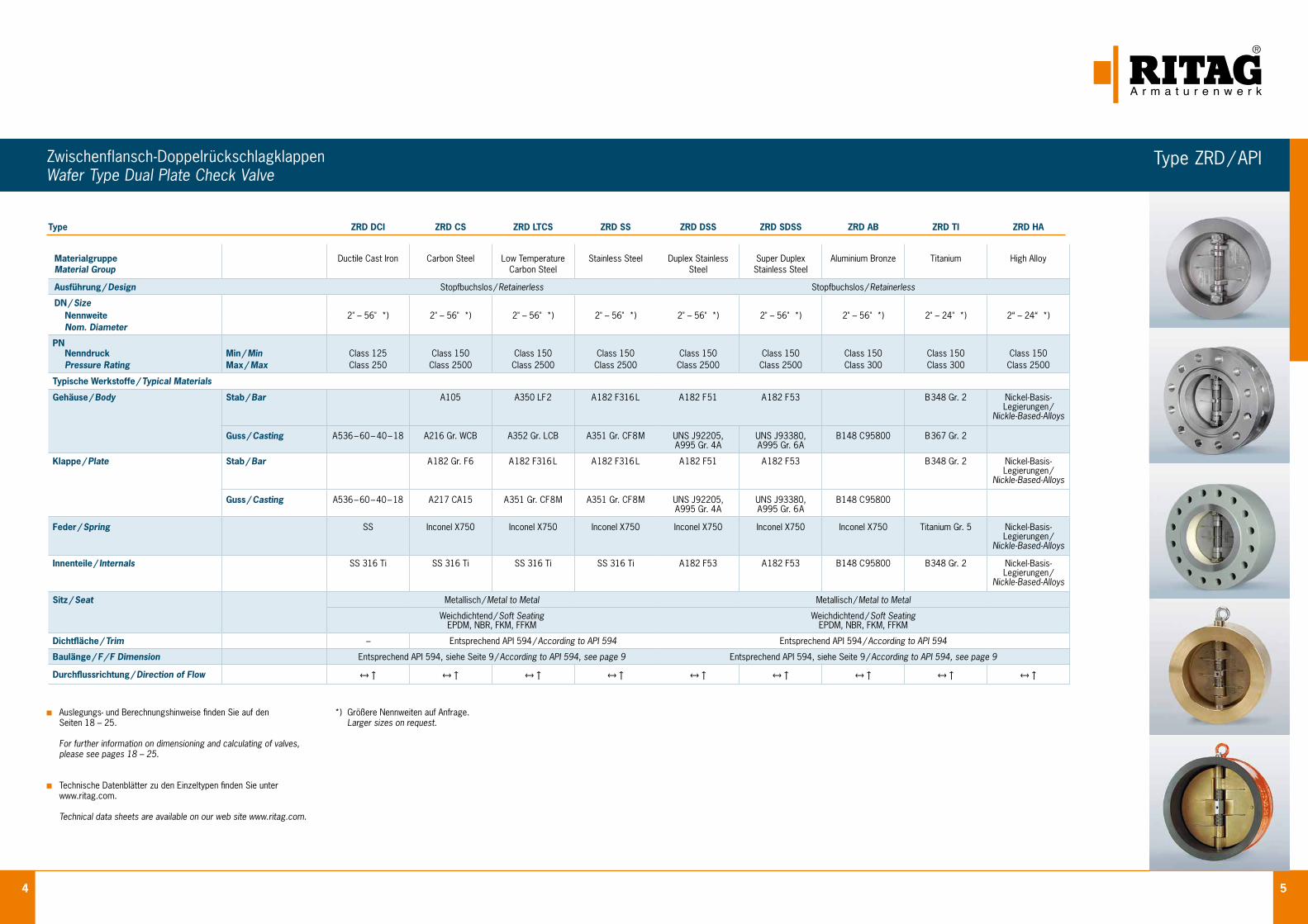
4 5
Zwischenflansch-DoppelrückschlagklappenWafer Type Dual Plate Check Valve
Type ZRD / API
Auslegungs- und Berechnungshinweise finden Sie auf den Seiten 18 – 25.
For further information on dimensioning and calculating of valves, please see pages 18 – 25.
Technische Datenblätter zu den Einzeltypen finden Sie unter www.ritag.com.
Technical data sheets are available on our web site www.ritag.com.
*) Größere Nennweiten auf Anfrage. Larger sizes on request.
Type ZRD DCI ZRD CS ZRD LTCS ZRD SS ZRD DSS ZRD SDSS ZRD AB ZRD TI ZRD HA
MaterialgruppeMaterial Group
Ductile Cast Iron Carbon Steel Low TemperatureCarbon Steel
Stainless Steel Duplex Stainless Steel
Super DuplexStainless Steel
Aluminium Bronze Titanium High Alloy
Ausführung / Design Stopfbuchslos / Retainerless Stopfbuchslos / Retainerless
DN / Size Nennweite 2" – 56" *) 2" – 56" *) 2" – 56" *) 2" – 56" *) 2" – 56" *) 2" – 56" *) 2" – 56" *) 2" – 24" *) 2“ – 24“ *)Nom. Diameter
PN Nenndruck Min / Min Class 125 Class 150 Class 150 Class 150 Class 150 Class 150 Class 150 Class 150 Class 150Pressure Rating Max / Max Class 250 Class 2500 Class 2500 Class 2500 Class 2500 Class 2500 Class 300 Class 300 Class 2500
Typische Werkstoffe / Typical Materials
Gehäuse / Body Stab / Bar A105 A350 LF2 A 182 F316 L A 182 F51 A 182 F53 B348 Gr. 2 Nickel - Basis - Legierungen /
Nickle - Based - Alloys
Guss / Casting A536 – 60 – 40 – 18 A216 Gr. WCB A352 Gr. LCB A351 Gr. CF8M UNS J92205,A995 Gr. 4A
UNS J93380,A995 Gr. 6A
B148 C95800 B367 Gr. 2
Klappe / Plate Stab / Bar A 182 Gr. F6 A 182 F316 L A 182 F316 L A 182 F51 A 182 F53 B348 Gr. 2 Nickel - Basis - Legierungen /
Nickle - Based - Alloys
Guss / Casting A536 – 60 – 40 – 18 A217 CA15 A351 Gr. CF8M A351 Gr. CF8M UNS J92205,A995 Gr. 4A
UNS J93380,A995 Gr. 6A
B148 C95800
Feder / Spring SS Inconel X750 Inconel X750 Inconel X750 Inconel X750 Inconel X750 Inconel X750 Titanium Gr. 5 Nickel - Basis - Legierungen /
Nickle - Based - Alloys
Innenteile / Internals SS 316 Ti SS 316 Ti SS 316 Ti SS 316 Ti A 182 F53 A 182 F53 B148 C95800 B348 Gr. 2 Nickel - Basis - Legierungen /
Nickle - Based - Alloys
Sitz / Seat Metallisch / Metal to Metal Metallisch / Metal to Metal
Weichdichtend / Soft Seating EPDM, NBR, FKM, FFKM
Weichdichtend / Soft Seating EPDM, NBR, FKM, FFKM
Dichtfläche / Trim – Entsprechend API 594 / According to API 594 Entsprechend API 594 / According to API 594
Baulänge / F / F Dimension Entsprechend API 594, siehe Seite 9 / According to API 594, see page 9 Entsprechend API 594, siehe Seite 9 / According to API 594, see page 9
Durchflussrichtung / Direction of Flow ↔↑ ↔↑ ↔↑ ↔↑ ↔↑ ↔↑ ↔↑ ↔↑ ↔↑
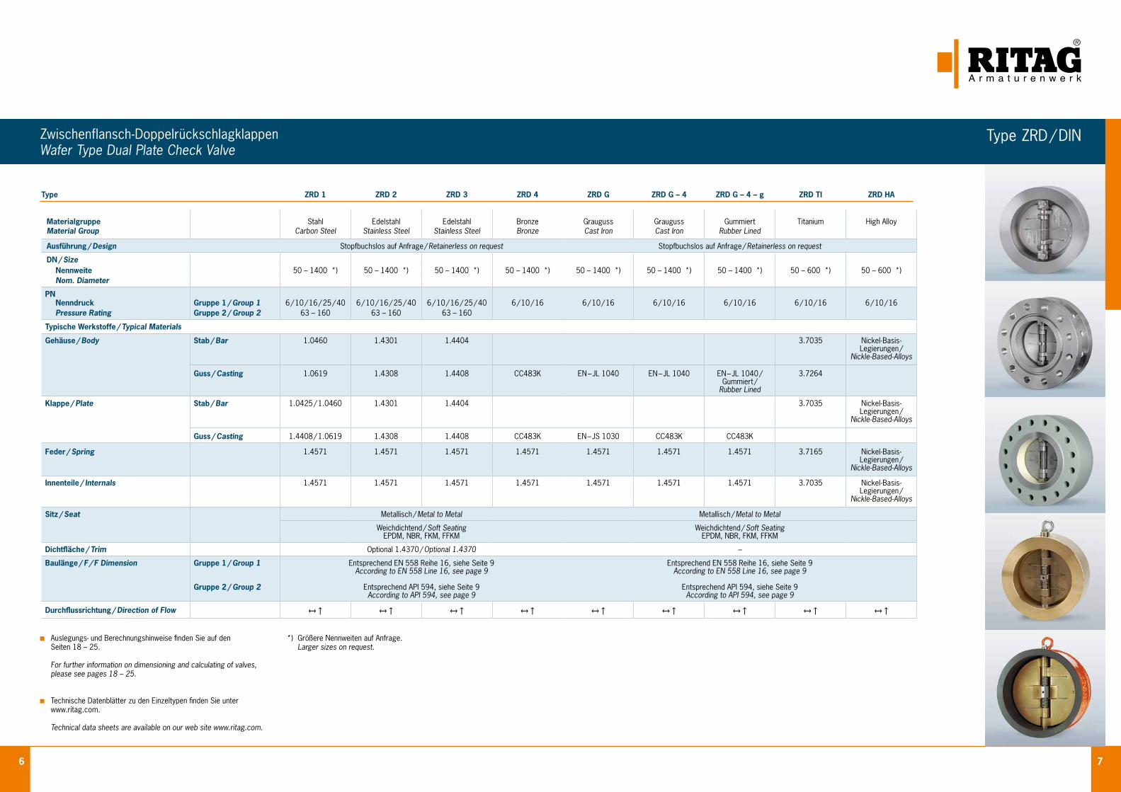
6 7
Zwischenflansch-DoppelrückschlagklappenWafer Type Dual Plate Check Valve
Type ZRD / DIN
Auslegungs- und Berechnungshinweise finden Sie auf den Seiten 18 – 25.
For further information on dimensioning and calculating of valves, please see pages 18 – 25.
Technische Datenblätter zu den Einzeltypen finden Sie unter www.ritag.com.
Technical data sheets are available on our web site www.ritag.com.
*) Größere Nennweiten auf Anfrage. Larger sizes on request.
Type ZRD 1 ZRD 2 ZRD 3 ZRD 4 ZRD G ZRD G – 4 ZRD G – 4 – g ZRD TI ZRD HA
MaterialgruppeMaterial Group
StahlCarbon Steel
EdelstahlStainless Steel
EdelstahlStainless Steel
BronzeBronze
GraugussCast Iron
GraugussCast Iron
GummiertRubber Lined
Titanium High Alloy
Ausführung / Design Stopfbuchslos auf Anfrage / Retainerless on request Stopfbuchslos auf Anfrage / Retainerless on request
DN / Size Nennweite 50 – 1400 *) 50 – 1400 *) 50 – 1400 *) 50 – 1400 *) 50 – 1400 *) 50 – 1400 *) 50 – 1400 *) 50 – 600 *) 50 – 600 *)Nom. Diameter
PN Nenndruck Gruppe 1 / Group 1 6 / 10 / 16 / 25 / 40 6 / 10 / 16 / 25 / 40 6 / 10 / 16 / 25 / 40 6 / 10 / 16 6 / 10 / 16 6 / 10 / 16 6 / 10 / 16 6 / 10 / 16 6 / 10 / 16Pressure Rating Gruppe 2 / Group 2 63 – 160 63 – 160 63 – 160
Typische Werkstoffe / Typical Materials
Gehäuse / Body Stab / Bar 1.0460 1.4301 1.4404 3.7035 Nickel - Basis -Legierungen /
Nickle - Based - Alloys
Guss / Casting 1.0619 1.4308 1.4408 CC483K EN – JL 1040 EN – JL 1040 EN – JL 1040 /Gummiert /
Rubber Lined
3.7264
Klappe / Plate Stab / Bar 1.0425 / 1.0460 1.4301 1.4404 3.7035 Nickel - Basis -Legierungen /
Nickle - Based - Alloys
Guss / Casting 1.4408 / 1.0619 1.4308 1.4408 CC483K EN – JS 1030 CC483K CC483K
Feder / Spring 1.4571 1.4571 1.4571 1.4571 1.4571 1.4571 1.4571 3.7165 Nickel - Basis -Legierungen /
Nickle - Based - Alloys
Innenteile / Internals 1.4571 1.4571 1.4571 1.4571 1.4571 1.4571 1.4571 3.7035 Nickel - Basis -Legierungen /
Nickle - Based - Alloys
Sitz / Seat Metallisch / Metal to Metal Metallisch / Metal to Metal
Weichdichtend / Soft Seating EPDM, NBR, FKM, FFKM
Weichdichtend / Soft Seating EPDM, NBR, FKM, FFKM
Dichtfläche / Trim Optional 1.4370 / Optional 1.4370 –
Baulänge / F / F Dimension Gruppe 1 / Group 1
Gruppe 2 / Group 2
Entsprechend EN 558 Reihe 16, siehe Seite 9According to EN 558 Line 16, see page 9
Entsprechend API 594, siehe Seite 9According to API 594, see page 9
Entsprechend EN 558 Reihe 16, siehe Seite 9According to EN 558 Line 16, see page 9
Entsprechend API 594, siehe Seite 9According to API 594, see page 9
Durchflussrichtung / Direction of Flow ↔↑ ↔↑ ↔↑ ↔↑ ↔↑ ↔↑ ↔↑ ↔↑ ↔↑
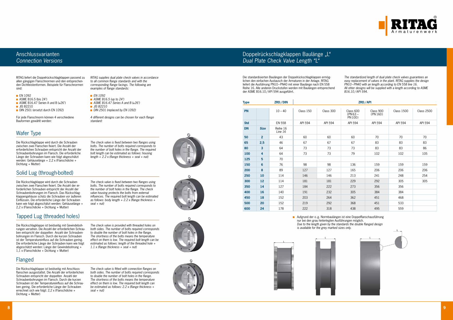
8 9
AnschlussvariantenConnection Versions
Wafer TypeDie Rückschlagklappe wird durch die Schrauben zwischen zwei Flanschen fixiert. Die Anzahl der erforderlichen Schrauben entspricht der Anzahl der Schraubenbohrungen im Flansch. Die erforderliche Länge der Schrauben kann wie folgt abgeschätzt werden: Gehäuselänge + 2,2 x (Flanschdicke + Dichtung + Mutter)
RITAG liefert die Doppelrückschlagklappen passend zu allen gängigen Flanschnormen und den entsprechen-den Dichtleistenformen. Beispiele für Flanschnormen sind:
EN 1092 ASME B16.5 (bis 24") ASME B16.47 Serien A und B (≥26") JIS B2210 DIN 2501 (ersetzt durch EN 1092)
Für jede Flanschnorm können 4 verschiedene Bauformen gewählt werden:
The check valve is fixed between two flanges using bolts. The number of bolts required corresponds to the number of bolt holes in the flange. The required bolt length can be estimated as follows: housing length + 2.2 x (flange thickness + seal + nut)
RITAG supplies dual plate check valves in accordance to all common flange standards and with the corresponding flange facings. The following are examples of flange standards:
EN 1092 ASME B16.5 (up to 24") ASME B16.47 Series A and B (≥26") JIS B2210 DIN 2501 (replaced by EN 1092)
4 different designs can be chosen for each flange standard:
Solid Lug (through-bolted)Die Rückschlagklappe wird durch die Schrauben zwischen zwei Flanschen fixiert. Die Anzahl der er- forderlichen Schrauben entspricht der Anzahl der Schraubenbohrungen im Flansch. Das Rückschlag-klappengehäuse schütz die Schrauben vor äußeren Einflüssen. Die erforderliche Länge der Schrauben kann wie folgt abgeschätzt werden: Gehäuselänge + 2,2 x (Flanschdicke + Dichtung + Mutter)
The check valve is fixed between two flanges using bolts. The number of bolts required corresponds to the number of bolt holes in the flange. The check valve housing protects the bolts from external influences. The required bolt length can be estimated as follows: body length + 2.2 x (flange thickness + seal + nut)
Tapped Lug (threaded holes)Die Rückschlagklappe ist beidseitig mit Gewindeboh-rungen versehen. Die Anzahl der erforderlichen Schrau- ben entspricht der doppelten Anzahl der Schrauben-bohrungen im Flansch. Durch die kurzen Schrauben ist der Temperatureinfluss auf die Schrauben gering. Die erforderliche Länge der Schrauben kann wie folgt abgeschätzt werden: Länge der Gewindebohrung + 1,1 x (Flanschdicke + Dichtung + Mutter)
The check valve is provided with threaded holes on both sides. The number of bolts required corresponds to double the number of bolt holes in the flange. The shortness of the bolts means the temperature effect on them is low. The required bolt length can be estimated as follows: length of the threaded hole + 1.1 x (flange thickness + seal + nut)
FlangedDie Rückschlagklappe ist beidseitig mit Anschluss-flanschen ausgestattet. Die Anzahl der erforderlichen Schrauben entspricht der doppelten Anzahl der Schraubenbohrungen im Flansch. Durch die kurzen Schrauben ist der Temperatureinfluss auf die Schrau-ben gering. Die erforderliche Länge der Schrauben errechnet sich wie folgt: 2,2 x (Flanschdicke + Dichtung + Mutter)
The check valve is fitted with connection flanges on both sides. The number of bolts required corresponds to double the number of bolt holes in the flange. The shortness of the bolts means the temperature effect on them is low. The required bolt length can be estimated as follows: 2.2 x (flange thickness + seal + nut)
Doppelrückschlagklappen Baulänge „L“Dual Plate Check Valve Length “L“
Die standardisierten Baulängen der Doppelrückschlagklappen ermög- lichen den einfachen Austausch der Armaturen in der Anlage. RITAG liefert die Ausführung PN10 – PN40 mit einer Baulänge nach EN 558 Reihe 16. Alle anderen Druckstufen werden mit Baulängen entsprechend der ASME B16.10 / API 594 ausgeführt.
The standardized length of dual plate check valves guarantees an easy replacement of valves in the plant. RITAG supplies the design PN10 – PN40 with an length according to EN 558 line 16.All ohter designs will be supplied with a length according to ASME B16.10 / API 594.
Aufgrund der o. g. Normbaulängen ist eine Doppelflanschausführung nur bei den grau hinterlegten Ausführungen möglich. Due to the length given by the standards the double flanged design is available for the grey marked sizes only.
Type ZRD / DIN ZRD / API
PN 10 – 40 Class 150 Class 300 Class 600 ( PN 63 – PN 100 )
Class 900 ( PN 160 )
Class 1500 Class 2500
Std EN 558 API 594 API 594 API 594 API 594 API 594 API 594
DN Size Reihe 16 Line 16
50 2 43 60 60 60 70 70 70
65 2,5 46 67 67 67 83 83 83
80 3 64 73 73 73 83 83 86
100 4 64 73 73 79 102 102 105
125 5 70
150 6 76 98 98 136 159 159 159
200 8 89 127 127 165 206 206 206
250 10 114 146 146 213 241 248 254
300 12 114 181 181 229 292 305 305
350 14 127 184 222 273 356 356
400 16 140 191 232 305 384 384
450 18 152 203 264 362 451 468
500 20 152 219 292 368 451 533
600 24 178 222 318 438 495 559
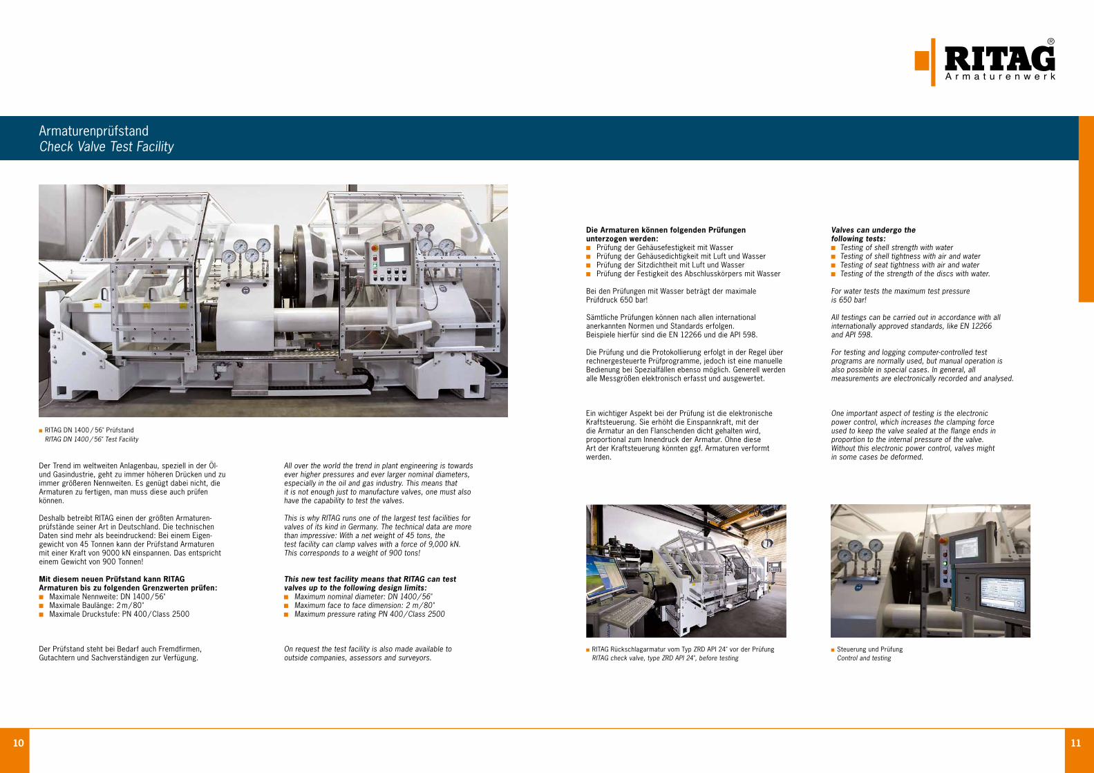
10 11
ArmaturenprüfstandCheck Valve Test Facility
Der Trend im weltweiten Anlagenbau, speziell in der Öl- und Gasindustrie, geht zu immer höheren Drücken und zu immer größeren Nennweiten. Es genügt dabei nicht, die Armaturen zu fertigen, man muss diese auch prüfen können.
Deshalb betreibt RITAG einen der größten Armaturen- prüfstände seiner Art in Deutschland. Die technischen Daten sind mehr als beeindruckend: Bei einem Eigen- gewicht von 45 Tonnen kann der Prüfstand Armaturen mit einer Kraft von 9000 kN einspannen. Das entspricht einem Gewicht von 900 Tonnen!
Mit diesem neuen Prüfstand kann RITAG Armaturen bis zu folgenden Grenzwerten prüfen: Maximale Nennweite: DN 1400 / 56" Maximale Baulänge: 2 m / 80" Maximale Druckstufe: PN 400 / Class 2500
Der Prüfstand steht bei Bedarf auch Fremdfirmen, Gutachtern und Sachverständigen zur Verfügung.
All over the world the trend in plant engineering is towards ever higher pressures and ever larger nominal diameters, especially in the oil and gas industry. This means that it is not enough just to manufacture valves, one must also have the capability to test the valves.
This is why RITAG runs one of the largest test facilities for valves of its kind in Germany. The technical data are more than impressive: With a net weight of 45 tons, the test facility can clamp valves with a force of 9,000 kN. This corresponds to a weight of 900 tons!
This new test facility means that RITAG can test valves up to the following design limits: Maximum nominal diameter: DN 1400 / 56" Maximum face to face dimension: 2 m / 80" Maximum pressure rating PN 400 / Class 2500
On request the test facility is also made available to outside companies, assessors and surveyors.
Die Armaturen können folgenden Prüfungen unterzogen werden: Prüfung der Gehäusefestigkeit mit Wasser Prüfung der Gehäusedichtigkeit mit Luft und Wasser Prüfung der Sitzdichtheit mit Luft und Wasser Prüfung der Festigkeit des Abschlusskörpers mit Wasser
Bei den Prüfungen mit Wasser beträgt der maximale Prüfdruck 650 bar!
Sämtliche Prüfungen können nach allen international anerkannten Normen und Standards erfolgen. Beispiele hierfür sind die EN 12266 und die API 598.
Die Prüfung und die Protokollierung erfolgt in der Regel über rechnergesteuerte Prüfprogramme, jedoch ist eine manuelle Bedienung bei Spezialfällen ebenso möglich. Generell werden alle Messgrößen elektronisch erfasst und ausgewertet.
Valves can undergo the following tests: Testing of shell strength with water Testing of shell tightness with air and water Testing of seat tightness with air and water Testing of the strength of the discs with water.
For water tests the maximum test pressure is 650 bar!
All testings can be carried out in accordance with all internationally approved standards, like EN 12266 and API 598.
For testing and logging computer-controlled test programs are normally used, but manual operation is also possible in special cases. In general, all measurements are electronically recorded and analysed.
RITAG DN 1400 / 56" Prüfstand RITAG DN 1400 / 56" Test Facility
Ein wichtiger Aspekt bei der Prüfung ist die elektronische Kraftsteuerung. Sie erhöht die Einspannkraft, mit der die Armatur an den Flanschenden dicht gehalten wird, proportional zum Innendruck der Armatur. Ohne diese Art der Kraftsteuerung könnten ggf. Armaturen verformt werden.
One important aspect of testing is the electronic power control, which increases the clamping force used to keep the valve sealed at the flange ends in proportion to the internal pressure of the valve. Without this electronic power control, valves might in some cases be deformed.
RITAG Rückschlagarmatur vom Typ ZRD API 24" vor der Prüfung RITAG check valve, type ZRD API 24", before testing
Steuerung und Prüfung Control and testing
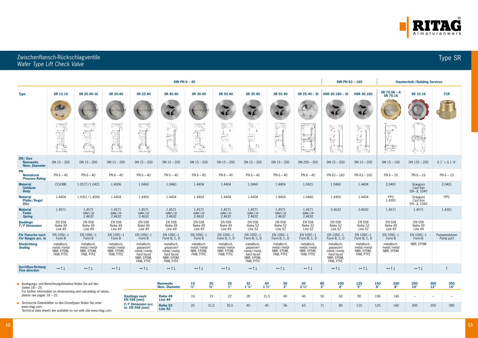
12 13
Zwischenflansch-Rückschlagventile Wafer Type Lift Check Valve
Auslegungs- und Berechnungshinweise finden Sie auf den Seiten 18 – 25.
For further information on dimensioning and calculating of valves, please see pages 18 – 25.
Technische Datenblätter zu den Einzeltypen finden Sie unter www.ritag.com.
Technical data sheets are available on our web site www.ritag.com.
NennweiteNom. Diameter
15½"
20¾"
251"
321 ¼"
401 ½"
502"
652 ½"
803"
1004"
1255"
1506"
2008"
25010"
30012"
35014"
Baulänge nach EN 558 [mm]F/ F Dimension acc. to. EN 558 [mm]
Reihe 49Line 49
16 19 22 28 31,5 40 46 50 60 90 106 140 – – –
Reihe 52Line 52
25 31,5 35,5 40 45 56 63 71 80 110 125 160 200 250 280
DIN PN 6 – 40 DIN PN 63 – 160 Haustechnik / Building Services
Type SR 12.16 SR 20.40–St SR 20.40 SR 22.40 SR 40.40 SR 30.40 SR 50.40 SR 35.40 SR 55.40 SR 25.40 – St HSR 20.160 – St HSR 30.160 SR 70.06 – KSR 70.16 SR 10.16 TCR
DN / Size Nennweite Nom. Diameter
DN 15 – 200 DN 15 – 200 DN 15 – 200 DN 15 – 200 DN 15 – 200 DN 15 – 200 DN 15 – 200 DN 15 – 200 DN 15 – 200 DN 250 – 350 DN 15 – 200 DN 15 – 200 DN 15 – 100 DN 125 – 200 G 1" + G 1 ¼"
PN Nenndruck Pressure Rating
PN 6 – 40 PN 6 – 40 PN 6 – 40 PN 6 – 40 PN 6 – 40 PN 6 – 40 PN 6 – 40 PN 6 – 40 PN 6 – 40 PN 6 – 40 PN 63 – 160 PN 63 – 160 PN 6 – 16 PN 6 – 16 PN 6 – 10
Material Gehäuse Body
CC438K 1.0577 / 1.0421 1.4006 1.0460 1.0460 1.4404 1.4404 1.0460 1.4404 1.0421 1.0460 1.4404 2.0401 Grauguss Cast Iron
EN – JL 1040
2.0401
Material Platte / Kegel Disc
1.4404 1.4301 / 1.4006 1.4404 1.4404 1.4404 1.4404 1.4404 1.4404 1.4404 1.0460 1.4404 1.4404 PPO1.4301
Grauguss Cast Iron
EN – JL 1040
PPO
Material Feder Spring
1.4571 1.4571oder / or2.4632
1.4571oder / or2.4632
1.4571oder / or2.4632
1.4571oder / or2.4632
1.4571oder / or2.4632
1.4571oder / or2.4632
1.4571oder / or2.4632
1.4571oder / or2.4632
1.4571oder / or2.4632
2.4632 2.4632 1.4571 1.4571 1.4301
BaulängeF / F Dimension
EN 558Reihe 49Line 49
EN 558Reihe 49Line 49
EN 558Reihe 49Line 49
EN 558Reihe 49Line 49
EN 558Reihe 49Line 49
EN 558Reihe 49Line 49
EN 558Reihe 49Line 49
EN 558Reihe 52Line 52
EN 558Reihe 52Line 52
EN 558Reihe 52Line 52
EN 558Reihe 52Line 52
EN 558Reihe 52Line 52
EN 558Reihe 49Line 49
EN 558Reihe 49Line 49
Für Flansche nachFor flanges acc. to
EN 1092 – 1Form B
EN 1092 – 1Form B
EN 1092 – 1Form B
EN 1092 – 1Form B
EN 1092 – 1Form B, C, D
EN 1092 – 1Form B
EN 1092 – 1Form B, C, D
EN 1092 – 1Form B, C, D
EN 1092 – 1Form B, C, D
EN 1092 – 1Form B, C, D
EN 1092 – 1Form B, C, D
EN 1092 – 1Form B, C, D
EN 1092 – 1Form B
EN 1092 – 1Form B
PumpenstutzenPump port
SitzdichtungSealing
metallisch,metal / metalNBR, EPDM,FKM, PTFE
metallisch,metal / metalNBR, EPDM,FKM, PTFE
metallisch,metal / metalNBR, EPDM,FKM, PTFE
metallisch, gepanzert
metal / metal, hard faced
NBR, EPDM,FKM, PTFE
metallisch, gepanzert
metal / metal, hard faced
NBR, EPDM,FKM, PTFE
metallisch,metal / metalNBR, EPDM,FKM, PTFE
metallisch,metal / metalNBR, EPDM,FKM, PTFE
metallisch, gepanzert
metal / metal, hard faced
NBR, EPDM,FKM, PTFE
metallisch,metal / metalNBR, EPDM,FKM, PTFE
metallisch,metal / metalNBR, EPDM,FKM, PTFE
metallisch, gepanzert
metal / metal, hard faced
NBR, EPDM,FKM, PTFE
metallisch,metal / metalNBR, EPDM,FKM, PTFE
metallisch,metal / metalNBR, EPDM
NBR, EPDM
Durchfluss-RichtungFlow direction
↔↑↓ ↔↑↓ ↔↑↓ ↔↑↓ ↔↑↓ ↔↑↓ ↔↑↓ ↔↑↓ ↔↑↓ ↔↑↓ ↔↑↓ ↔↑↓ ↔↑↓ ↔↑↓ ↑
Type SR
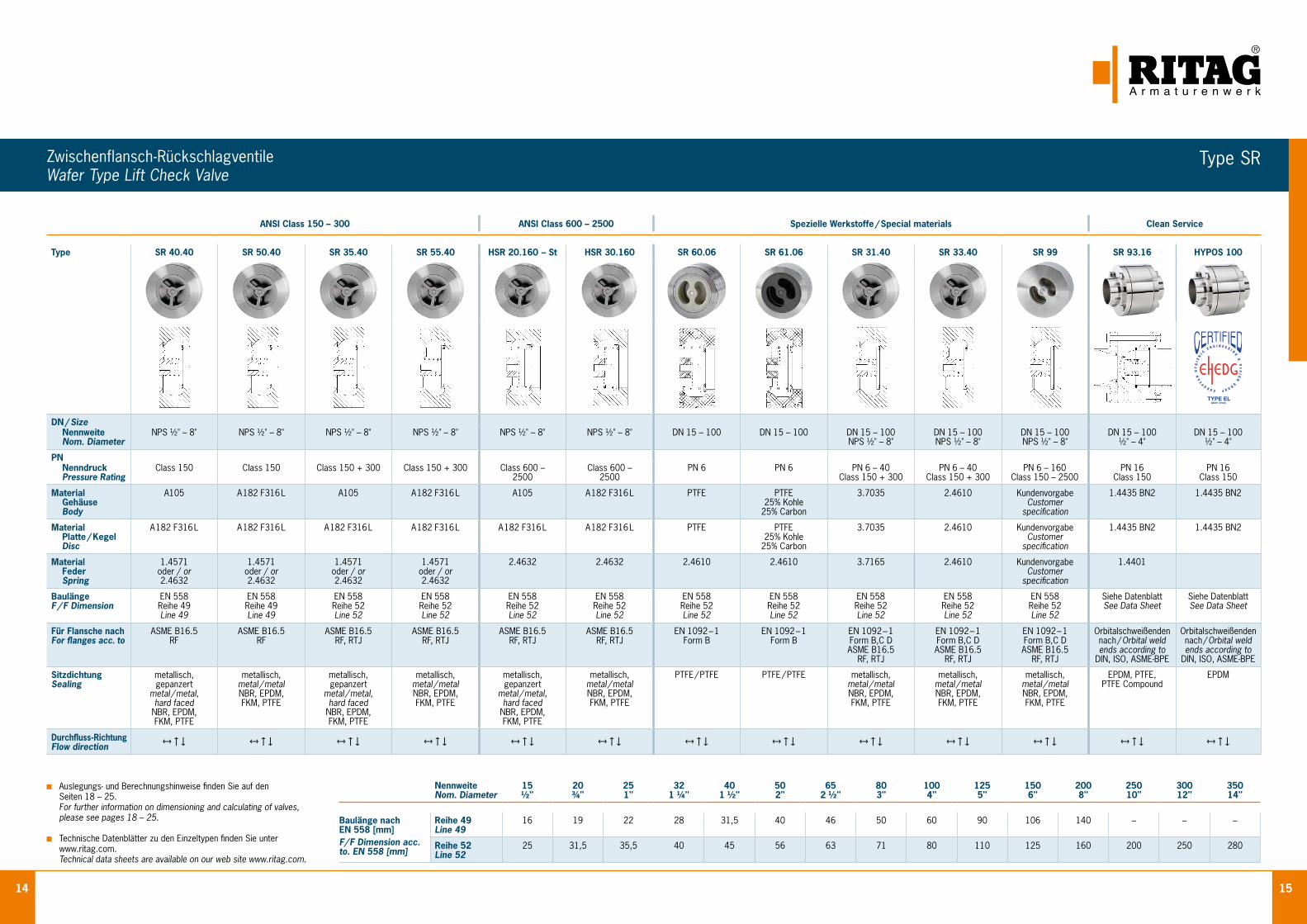
14 15
Zwischenflansch-Rückschlagventile Wafer Type Lift Check Valve
Auslegungs- und Berechnungshinweise finden Sie auf den Seiten 18 – 25.
For further information on dimensioning and calculating of valves, please see pages 18 – 25.
Technische Datenblätter zu den Einzeltypen finden Sie unter www.ritag.com.
Technical data sheets are available on our web site www.ritag.com.
NennweiteNom. Diameter
15½"
20¾"
251"
321 ¼"
401 ½"
502"
652 ½"
803"
1004"
1255"
1506"
2008"
25010"
30012"
35014"
Baulänge nach EN 558 [mm] F/ F Dimension acc. to. EN 558 [mm]
Reihe 49Line 49
16 19 22 28 31,5 40 46 50 60 90 106 140 – – –
Reihe 52Line 52
25 31,5 35,5 40 45 56 63 71 80 110 125 160 200 250 280
ANSI Class 150 – 300 ANSI Class 600 – 2500 Spezielle Werkstoffe / Special materials Clean Service
Type SR 40.40 SR 50.40 SR 35.40 SR 55.40 HSR 20.160 – St HSR 30.160 SR 60.06 SR 61.06 SR 31.40 SR 33.40 SR 99 SR 93.16 HYPOS 100
DN / Size Nennweite Nom. Diameter
NPS ½" – 8" NPS ½" – 8" NPS ½" – 8" NPS ½" – 8" NPS ½" – 8" NPS ½" – 8" DN 15 – 100 DN 15 – 100 DN 15 – 100 NPS ½" – 8"
DN 15 – 100 NPS ½" – 8"
DN 15 – 100 NPS ½" – 8"
DN 15 – 100 ½" – 4"
DN 15 – 100 ½" – 4"
PN Nenndruck Pressure Rating
Class 150 Class 150 Class 150 + 300 Class 150 + 300 Class 600 –2500
Class 600 –2500
PN 6 PN 6 PN 6 – 40Class 150 + 300
PN 6 – 40Class 150 + 300
PN 6 – 160Class 150 – 2500
PN 16Class 150
PN 16Class 150
Material Gehäuse Body
A105 A 182 F316 L A105 A 182 F316 L A105 A 182 F316 L PTFE PTFE25% Kohle
25% Carbon
3.7035 2.4610 KundenvorgabeCustomer
specification
1.4435 BN2 1.4435 BN2
Material Platte / Kegel Disc
A 182 F316 L A 182 F316 L A 182 F316 L A 182 F316 L A 182 F316 L A 182 F316 L PTFE PTFE25% Kohle
25% Carbon
3.7035 2.4610 KundenvorgabeCustomer
specification
1.4435 BN2 1.4435 BN2
Material Feder Spring
1.4571oder / or2.4632
1.4571oder / or2.4632
1.4571oder / or2.4632
1.4571oder / or2.4632
2.4632 2.4632 2.4610 2.4610 3.7165 2.4610 KundenvorgabeCustomer
specification
1.4401
BaulängeF / F Dimension
EN 558Reihe 49Line 49
EN 558Reihe 49Line 49
EN 558Reihe 52Line 52
EN 558Reihe 52Line 52
EN 558Reihe 52Line 52
EN 558Reihe 52Line 52
EN 558Reihe 52Line 52
EN 558Reihe 52Line 52
EN 558Reihe 52Line 52
EN 558Reihe 52Line 52
EN 558Reihe 52Line 52
Siehe DatenblattSee Data Sheet
Siehe DatenblattSee Data Sheet
Für Flansche nachFor flanges acc. to
ASME B16.5RF
ASME B16.5RF
ASME B16.5RF, RTJ
ASME B16.5RF, RTJ
ASME B16.5RF, RTJ
ASME B16.5RF, RTJ
EN 1092 – 1Form B
EN 1092 – 1Form B
EN 1092 – 1Form B,C DASME B16.5
RF, RTJ
EN 1092 – 1Form B,C DASME B16.5
RF, RTJ
EN 1092 – 1Form B,C DASME B16.5
RF, RTJ
Orbitalschweißenden nach / Orbital weld ends according to
DIN, ISO, ASME-BPE
Orbitalschweißenden nach / Orbital weld ends according to
DIN, ISO, ASME-BPE
SitzdichtungSealing
metallisch, gepanzert
metal / metal, hard faced
NBR, EPDM,FKM, PTFE
metallisch,metal / metalNBR, EPDM,FKM, PTFE
metallisch, gepanzert
metal / metal, hard faced
NBR, EPDM,FKM, PTFE
metallisch,metal / metalNBR, EPDM,FKM, PTFE
metallisch, gepanzert
metal / metal, hard faced
NBR, EPDM,FKM, PTFE
metallisch,metal / metalNBR, EPDM,FKM, PTFE
PTFE / PTFE PTFE / PTFE metallisch,metal / metalNBR, EPDM,FKM, PTFE
metallisch,metal / metalNBR, EPDM,FKM, PTFE
metallisch,metal / metalNBR, EPDM,FKM, PTFE
EPDM, PTFE,PTFE Compound
EPDM
Durchfluss-RichtungFlow direction
↔↑↓ ↔↑↓ ↔↑↓ ↔↑↓ ↔↑↓ ↔↑↓ ↔↑↓ ↔↑↓ ↔↑↓ ↔↑↓ ↔↑↓ ↔↑↓ ↔↑↓
Type SR
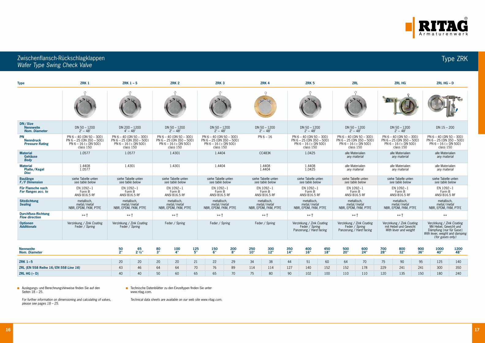
16 17
Zwischenflansch-Rückschlagklappen Wafer Type Swing Check Valve
Type ZRK 1 ZRK 1 – S ZRK 2 ZRK 3 ZRK 4 ZRK 5 ZRL ZRL HG ZRL HG – D
DN / Size Nennweite Nom. Diameter
DN 50 – 1200 2" – 48"
DN 200 – 1200 4" – 48"
DN 50 – 1200 2" – 48"
DN 50 – 1200 2" – 48"
DN 50 – 1200 2" – 48"
DN 50 – 1200 2" – 48"
DN 50 – 1200 2" – 48"
DN 50 – 1200 2" – 48"
DN 15 – 200
PN Nenndruck Pressure Rating
PN 6 – 40 ( DN 50 – 300 ) PN 6 – 25 ( DN 350 – 500 )
PN 6 – 16 ( > DN 500 ) class 150
PN 6 – 40 ( DN 50 – 300 ) PN 6 – 25 ( DN 350 – 500 )
PN 6 – 16 ( > DN 500 ) class 150
PN 6 – 40 ( DN 50 – 300 ) PN 6 – 25 ( DN 350 – 500 )
PN 6 – 16 ( > DN 500 ) class 150
PN 6 – 40 ( DN 50 – 300 ) PN 6 – 25 ( DN 350 – 500 )
PN 6 – 16 ( > DN 500 ) class 150
PN 6 – 16 PN 6 – 40 ( DN 50 – 300 ) PN 6 – 25 ( DN 350 – 500 )
PN 6 – 16 ( > DN 500 ) class 150
PN 6 – 40 ( DN 50 – 300 ) PN 6 – 25 ( DN 350 – 500 )
PN 6 – 16 ( > DN 500 ) class 150
PN 6 – 40 ( DN 50 – 300 ) PN 6 – 25 ( DN 350 – 500 )
PN 6 – 16 ( > DN 500 ) class 150
PN 6 – 40 ( DN 50 – 300 ) PN 6 – 25 ( DN 350 – 500 )
PN 6 – 16 ( > DN 500 ) class 150
Material Gehäuse Body
1.0577 1.0577 1.4301 1.4404 CC483K 1.0425 alle Materialien any material
alle Materialien any material
alle Materialien any material
Material Platte / Kegel Disc
1.44081.0577
1.4301 1.4301 1.4404 1.44081.4404
1.44081.0425
alle Materialien any material
alle Materialien any material
alle Materialien any material
BaulängeF / F Dimension
siehe Tabelle untensee table below
siehe Tabelle untensee table below
siehe Tabelle untensee table below
siehe Tabelle untensee table below
siehe Tabelle untensee table below
siehe Tabelle untensee table below
siehe Tabelle untensee table below
siehe Tabelle untensee table below
siehe Tabelle untensee table below
Für Flansche nachFor flanges acc. to
EN 1092 – 1Form B
ANSI B16.5 RF
EN 1092 – 1Form B
ANSI B16.5 RF
EN 1092 – 1Form B
ANSI B16.5 RF
EN 1092 – 1Form B
ANSI B16.5 RF
EN 1092 – 1Form B
ANSI B16.5 RF
EN 1092 – 1Form B
ANSI B16.5 RF
EN 1092 – 1Form B
ANSI B16.5 RF
EN 1092 – 1Form B
ANSI B16.5 RF
EN 1092 – 1Form B
ANSI B16.5 RF
SitzdichtungSealing
metallisch,metal / metal
NBR, EPDM, FKM, PTFE
metallisch,metal / metal
NBR, EPDM, FKM, PTFE
metallisch,metal / metal
NBR, EPDM, FKM, PTFE
metallisch,metal / metal
NBR, EPDM, FKM, PTFE
metallisch,metal / metal
NBR, EPDM, FKM, PTFE
metallisch,metal / metal
NBR, EPDM, FKM, PTFE
metallisch,metal / metal
NBR, EPDM, FKM, PTFE
metallisch,metal / metal
NBR, EPDM, FKM, PTFE
metallisch,metal / metal
NBR, EPDM, FKM, PTFE
Durchfluss-RichtungFlow direction
↔↑ ↔↑ ↔↑ ↔↑ ↔↑ ↔↑ ↔↑ ↔↑ ↔
OptionenAdditionals
Verzinkung / Zink CoatingFeder / Spring
Verzinkung / Zink CoatingFeder / Spring
Feder / Spring Feder / Spring Feder / Spring Verzinkung / Zink CoatingFeder / Spring
Panzerung / Hard facing
Verzinkung / Zink CoatingFeder / Spring
Panzerung / Hard facing
Verzinkung / Zink Coatingmit Hebel und GewichtWith lever and weight
Verzinkung / Zink CoatingMit Hebel, Gewicht und
Dämpfung ( nur für Gase )With lever, weight and damping
( for gases only )
Auslegungs- und Berechnungshinweise finden Sie auf den Seiten 18 – 25.
For further information on dimensioning and calculating of valves, please see pages 18 – 25.
Technische Datenblätter zu den Einzeltypen finden Sie unter www.ritag.com.
Technical data sheets are available on our web site www.ritag.com.
NennweiteNom. Diameter
50 2"
65 2 ½"
80 3"
100 4"
125 5"
150 6"
200 8"
250 10"
300 12"
350 14"
400 16"
450 18"
500 20"
600 24"
700 28"
800 32"
900 36"
1000 40"
1200 48"
ZRK 1 – 5 20 20 20 20 21 22 29 34 38 44 51 60 64 70 75 90 95 125 140
ZRL (EN 558 Reihe 16 / EN 558 Line 16) 43 46 64 64 70 76 89 114 114 127 140 152 152 178 229 241 241 300 350
ZRL HG ( – D) 40 40 50 60 65 65 70 75 80 90 102 100 110 110 120 135 150 180 240
Type ZRK
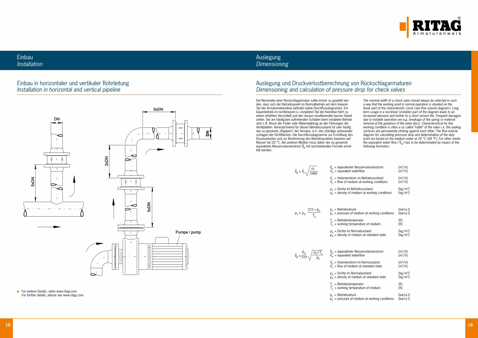
18 19
Einbau in horizontaler und vertikaler Rohrleitung Installation in horizontal and vertical pipeline
EinbauInstallation
Auslegung und Druckverlustberechnung von Rückschlagarmaturen Dimensioning and calculation of pressure drop for check valves
AuslegungDimensioning
Die Nennweite einer Rückschlagarmatur sollte immer so gewählt wer-den, dass sich der Betriebspunkt im Normalbetrieb auf dem linearen Teil der Armaturenkennlinie befindet (siehe Durchflussdiagramm). Ein Dauerbetrieb im nichtlinearen (= instabilen) Teil der Kennlinie führt zu einem erhöhten Verschleiß und den daraus resultierenden kurzen Stand-zeiten. Die am häufigsten auftretenden Schäden beim instabilen Betrieb sind z. B. Bruch der Feder oder Materialabtrag an den Führungen der Ventilplatten. Kennzeichnend für diesen Betriebszustand ist sehr häufig das so genannte „Klappern“ der Armatur, d. h. das ständige aufeinander schlagen der Dichtflächen. Die Durchflussdiagramme zur Ermittlung des Druckverlustes und zur Bestimmung des Betriebspunktes basieren auf Wasser bei 20 °C. Bei anderen Medien muss daher der so genannte äquivalente Wasservolumenstrom V
.W mit nachstehenden Formeln ermit-
telt werden:
The nominal width of a check valve should always be selected in such a way that the working point in normal operation is situated on the linear part of the characteristic curve ( see flow volume diagram ). Long term usage in a non-linear ( instable ) part of the diagram leads to an increased abrasion and further to a short service life. Frequent damages due to instable operation are e.g. breakage of the spring or material removal at the guidance of the valve discs. Characteristical for this working condition is often a so called “rattle” of the valve i. e. the sealing surfaces are permanently striking against each other. The flow volume diagram for calculating pressure drop and determination of the duty point are based on the medium water at 20 °C ( 68 °F ). For other media the equivalent water flow ( V
.W ) has to be determinated by means of the
following formulars:
V.W = V
. x
ρX
1000
ρX = ρN
273*pX
TX
V.W =
ρN*TX
pX
V.
N
519
V.
W = äquivalenter Wasservolumenstrom [m3/h] V.
W = equivalent waterflow [m3/h]
V.
X = Volumenstrom im Betriebszustand [m3/h] V.
X = flow of medium at working conditions [m3/h]
ρX = Dichte im Betriebszustand [kg/m3] ρX = density of medium at working conditions [kg/m3]
pX = Betriebsdruck [bar( a )] pX = pressure of medium at working conditions [bar( a )]
TX = Betriebstemperatur [K] TX = working temperature of medium [K]
ρN = Dichte im Normalzustand [kg/m3] ρN = density of medium at standard state [kg/m3]
V.
W = äquivalenter Wasservolumenstrom [m3/h] V.
W = equivalent waterflow [m3/h]
V.
N = Volumenstrom im Normzustand [m3/h] V.
N = flow of medium at standard state [m3/h]
ρN = Dichte im Normalzustand [kg/m3] ρN = density of medium at standard state [kg/m3]
TX = Betriebstemperatur [K] TX = working temperature of medium [K]
pX = Betriebsdruck [bar( a )] pX = pressure of medium at working conditions [bar( a )]
Für weitere Details, siehe www.ritag.com. For further details, please see www.ritag.com.
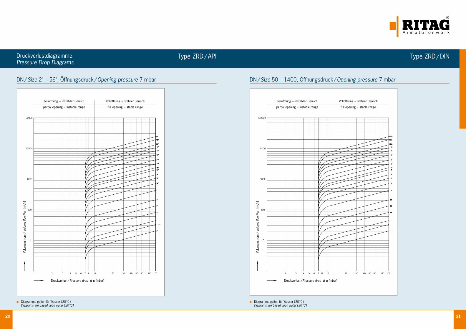
20 21
DruckverlustdiagrammePressure Drop Diagrams
Diagramme gelten für Wasser ( 20 °C ) Diagrams are based upon water ( 20 °C )
Diagramme gelten für Wasser ( 20 °C ) Diagrams are based upon water ( 20 °C )
DN / Size 2" – 56", Öffnungsdruck / Opening pressure 7 mbar DN / Size 50 – 1400, Öffnungsdruck / Opening pressure 7 mbar
Druckverlust / Pressure drop Δ p [mbar] Druckverlust / Pressure drop Δ p [mbar]
Volu
men
stro
m /
vol
ume
flow
Vw
[m
3 /h]
Volu
men
stro
m /
vol
ume
flow
Vw
[m
3 /h]
Teilöffnung = instabiler Bereich
partial opening = instable range
Teilöffnung = instabiler Bereich
partial opening = instable range
Vollöffnung = stabiler Bereich
full opening = stable range
Vollöffnung = stabiler Bereich
full opening = stable range
Type ZRD / API Type ZRD / DIN
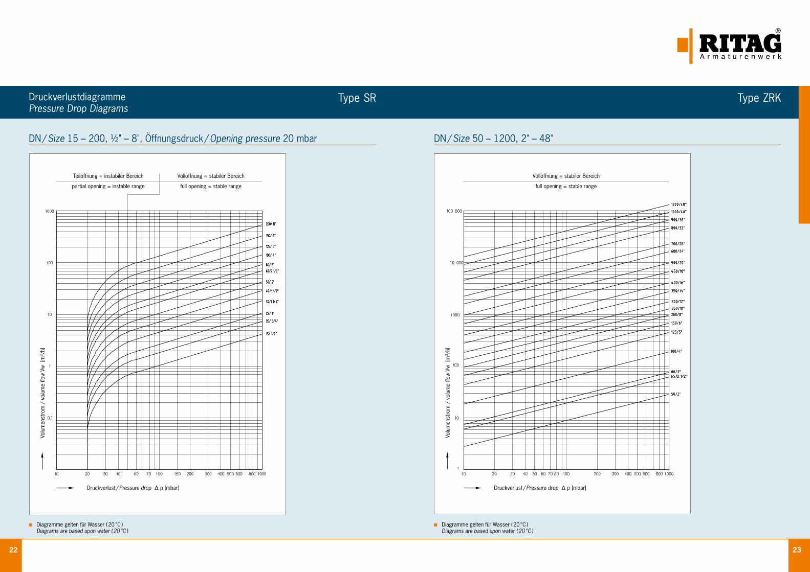
22 23
Druckverlustdiagramme Pressure Drop Diagrams
Diagramme gelten für Wasser ( 20 °C ) Diagrams are based upon water ( 20 °C )
Diagramme gelten für Wasser ( 20 °C ) Diagrams are based upon water ( 20 °C )
DN / Size 15 – 200, ½" – 8", Öffnungsdruck / Opening pressure 20 mbar DN / Size 50 – 1200, 2" – 48"
Teilöffnung = instabiler Bereich
partial opening = instable range
Vollöffnung = stabiler Bereich
full opening = stable range
Vollöffnung = stabiler Bereich
full opening = stable range
Druckverlust / Pressure drop Δ p [mbar] Druckverlust / Pressure drop Δ p [mbar]
Volu
men
stro
m /
vol
ume
flow
Vw
[m
3 /h]
Volu
men
stro
m /
vol
ume
flow
Vw
[m
3 /h]
Type SR Type ZRK
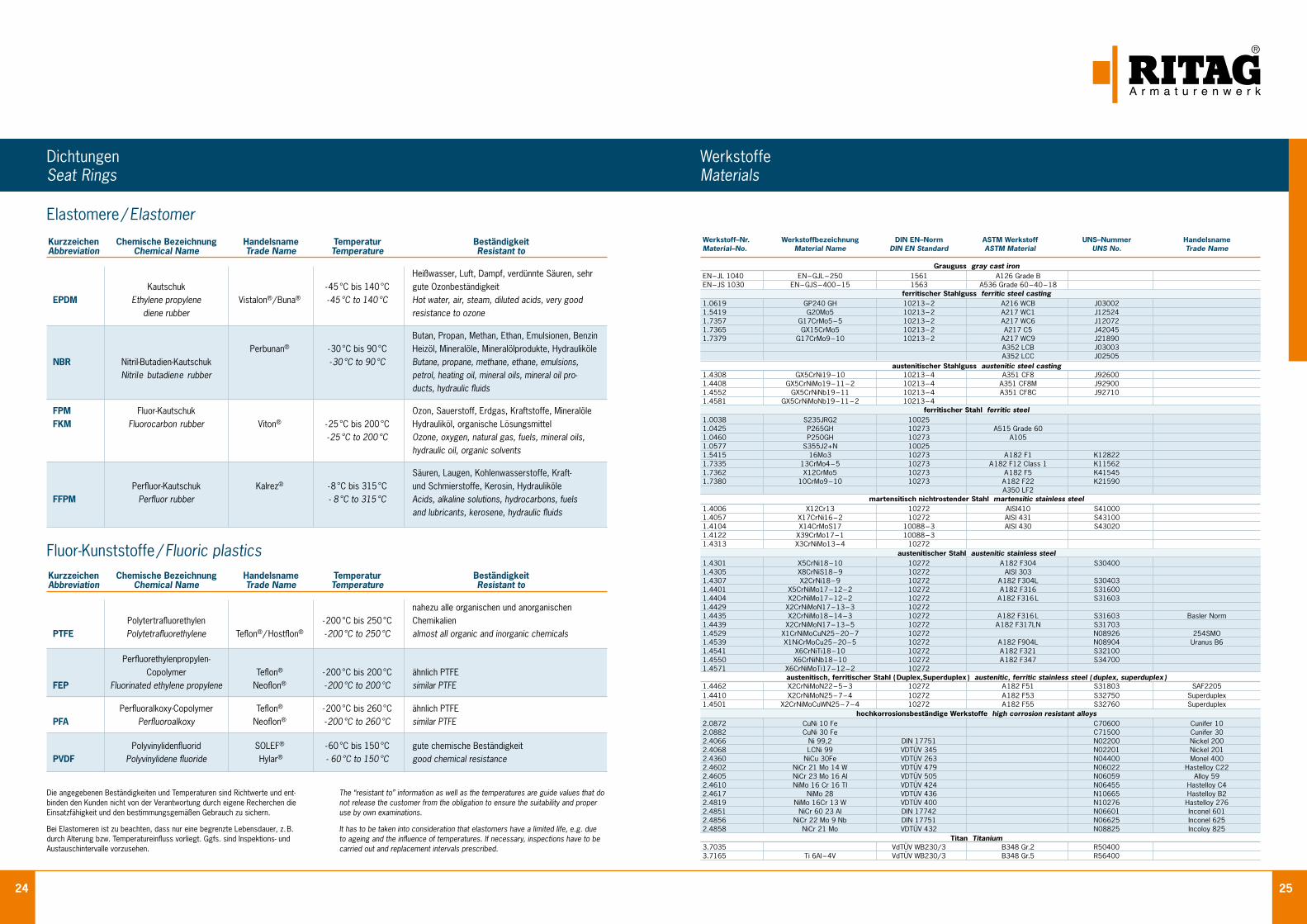
24 25
Kurzzeichen Chemische Bezeichnung Handelsname Temperatur BeständigkeitAbbreviation Chemical Name Trade Name Temperature Resistant to nahezu alle organischen und anorganischen Polytertrafluorethylen - 200 °C bis 250 °C Chemikalien PTFE Polytetrafluorethylene Teflon® / Hostflon® - 200 °C to 250 °C almost all organic and inorganic chemicals Perfluorethylenpropylen- Copolymer Teflon® - 200 °C bis 200 °C ähnlich PTFE FEP Fluorinated ethylene propylene Neoflon® - 200 °C to 200 °C similar PTFE Perfluoralkoxy-Copolymer Teflon® - 200 °C bis 260 °C ähnlich PTFE PFA Perfluoroalkoxy Neoflon® - 200 °C to 260 °C similar PTFE Polyvinylidenfluorid SOLEF® - 60 °C bis 150 °C gute chemische Beständigkeit PVDF Polyvinylidene fluoride Hylar® - 60 °C to 150 °C good chemical resistance
Die angegebenen Beständigkeiten und Temperaturen sind Richtwerte und ent-binden den Kunden nicht von der Verantwortung durch eigene Recherchen die Einsatzfähigkeit und den bestimmungsgemäßen Gebrauch zu sichern.
Bei Elastomeren ist zu beachten, dass nur eine begrenzte Lebensdauer, z. B. durch Alterung bzw. Temperatureinfluss vorliegt. Ggfs. sind Inspektions- und Austauschintervalle vorzusehen.
Elastomere / Elastomer
Fluor-Kunststoffe / Fluoric plastics
The “resistant to” information as well as the temperatures are guide values that do not release the customer from the obligation to ensure the suitability and proper use by own examinations.
It has to be taken into consideration that elastomers have a limited life, e.g. due to ageing and the influence of temperatures. If necessary, inspections have to be carried out and replacement intervals prescribed.
Kurzzeichen Chemische Bezeichnung Handelsname Temperatur BeständigkeitAbbreviation Chemical Name Trade Name Temperature Resistant to Heißwasser, Luft, Dampf, verdünnte Säuren, sehr Kautschuk - 45 °C bis 140 °C gute Ozonbeständigkeit EPDM Ethylene propylene Vistalon® / Buna® - 45 °C to 140 °C Hot water, air, steam, diluted acids, very good diene rubber resistance to ozone Butan, Propan, Methan, Ethan, Emulsionen, Benzin Perbunan® - 30 °C bis 90 °C Heizöl, Mineralöle, Mineralölprodukte, Hydrauliköle NBR Nitril-Butadien-Kautschuk - 30 °C to 90 °C Butane, propane, methane, ethane, emulsions, Nitrile butadiene rubber petrol, heating oil, mineral oils, mineral oil pro- ducts, hydraulic fluids
FPM Fluor-Kautschuk Ozon, Sauerstoff, Erdgas, Kraftstoffe, Mineralöle FKM Fluorocarbon rubber Viton® - 25 °C bis 200 °C Hydrauliköl, organische Lösungsmittel - 25 °C to 200 °C Ozone, oxygen, natural gas, fuels, mineral oils, hydraulic oil, organic solvents
Säuren, Laugen, Kohlen wasserstoffe, Kraft- Perfluor-Kautschuk Kalrez® - 8 °C bis 315 °C und Schmierstoffe, Kerosin, Hydrauliköle FFPM Perfluor rubber - 8 °C to 315 °C Acids, alkaline solutions, hydrocarbons, fuels and lubricants, kerosene, hydraulic fluids
Werkstoff–Nr. Werkstoffbezeichnung DIN EN–Norm ASTM Werkstoff UNS–Nummer Handelsname Material–No. Material Name DIN EN Standard ASTM Material UNS No. Trade Name Grauguss gray cast ironEN – JL 1040 EN – GJL – 250 1561 A126 Grade B EN – JS 1030 EN – GJS – 400 – 15 1563 A536 Grade 60 – 40 – 18 ferritischer Stahlguss ferritic steel casting 1.0619 GP240 GH 10213 – 2 A216 WCB J03002 1.5419 G20Mo5 10213 – 2 A217 WC1 J12524 1.7357 G17CrMo5 – 5 10213 – 2 A217 WC6 J12072 1.7365 GX15CrMo5 10213 – 2 A217 C5 J42045 1.7379 G17CrMo9 – 10 10213 – 2 A217 WC9 J21890 A352 LCB J03003 A352 LCC J02505 austenitischer Stahlguss austenitic steel casting1.4308 GX5CrNi19 – 10 10213 – 4 A351 CF8 J92600 1.4408 GX5CrNiMo19 – 11 – 2 10213 – 4 A351 CF8M J92900 1.4552 GX5CrNiNb19 – 11 10213 – 4 A351 CF8C J92710 1.4581 GX5CrNiMoNb19 – 11 – 2 10213 – 4 ferritischer Stahl ferritic steel1.0038 S235JRG2 10025 1.0425 P265GH 10273 A515 Grade 60 1.0460 P250GH 10273 A105 1.0577 S355J2+N 10025 1.5415 16Mo3 10273 A 182 F1 K12822 1.7335 13CrMo4 – 5 10273 A 182 F12 Class 1 K11562 1.7362 X12CrMo5 10273 A 182 F5 K41545 1.7380 10CrMo9 – 10 10273 A 182 F22 K21590 A350 LF2 martensitisch nichtrostender Stahl martensitic stainless steel 1.4006 X12Cr13 10272 AISI410 S41000 1.4057 X17CrNi16 – 2 10272 AISI 431 S43100 1.4104 X14CrMoS17 10088 – 3 AISI 430 S43020 1.4122 X39CrMo17 – 1 10088 – 3 1.4313 X3CrNiMo13 – 4 10272 austenitischer Stahl austenitic stainless steel 1.4301 X5CrNi18 – 10 10272 A 182 F304 S30400 1.4305 X8CrNiS18 – 9 10272 AISI 303 1.4307 X2CrNi18 – 9 10272 A 182 F304L S30403 1.4401 X5CrNiMo17 – 12 – 2 10272 A 182 F316 S31600 1.4404 X2CrNiMo17 – 12 – 2 10272 A 182 F316 L S31603 1.4429 X2CrNiMoN17 – 13 – 3 10272 1.4435 X2CrNiMo18 – 14 – 3 10272 A 182 F316 L S31603 Basler Norm 1.4439 X2CrNiMoN17 – 13 – 5 10272 A 182 F317LN S31703 1.4529 X1CrNiMoCuN25 – 20 – 7 10272 N08926 254SMO 1.4539 X1NiCrMoCu25 – 20 – 5 10272 A 182 F904L N08904 Uranus B6 1.4541 X6CrNiTi18 – 10 10272 A 182 F321 S32100 1.4550 X6CrNiNb18 – 10 10272 A 182 F347 S34700 1.4571 X6CrNiMoTi17 – 12 – 2 10272 austenitisch, ferritischer Stahl ( Duplex,Superduplex ) austenitic, ferritic stainless steel ( duplex, superduplex )1.4462 X2CrNiMoN22 – 5 – 3 10272 A 182 F51 S31803 SAF2205 1.4410 X2CrNiMoN25 – 7 – 4 10272 A 182 F53 S32750 Superduplex 1.4501 X2CrNiMoCuWN25 – 7 – 4 10272 A 182 F55 S32760 Superduplex hochkorrosionsbeständige Werkstoffe high corrosion resistant alloys2.0872 CuNi 10 Fe C70600 Cunifer 10 2.0882 CuNi 30 Fe C71500 Cunifer 30 2.4066 Ni 99,2 DIN 17751 N02200 Nickel 200 2.4068 LCNi 99 VDTÜV 345 N02201 Nickel 201 2.4360 NiCu 30Fe VDTÜV 263 N04400 Monel 400 2.4602 NiCr 21 Mo 14 W VDTÜV 479 N06022 Hastelloy C22 2.4605 NiCr 23 Mo 16 Al VDTÜV 505 N06059 Alloy 59 2.4610 NiMo 16 Cr 16 TI VDTÜV 424 N06455 Hastelloy C4 2.4617 NiMo 28 VDTÜV 436 N10665 Hastelloy B2 2.4819 NiMo 16Cr 13 W VDTÜV 400 N10276 Hastelloy 276 2.4851 NiCr 60 23 Al DIN 17742 N06601 Inconel 601 2.4856 NiCr 22 Mo 9 Nb DIN 17751 N06625 Inconel 625 2.4858 NiCr 21 Mo VDTÜV 432 N08825 Incoloy 825 Titan Titanium3.7035 VdTÜV WB230/3 B348 Gr.2 R50400 3.7165 Ti 6Al – 4V VdTÜV WB230/3 B348 Gr.5 R56400
DichtungenSeat Rings
WerkstoffeMaterials
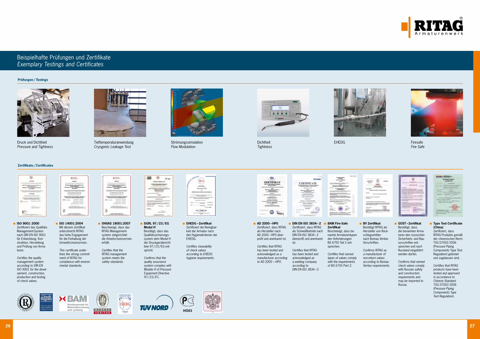
26 27
Prüfungen / Testings
Zertifikate / Certificates
Beispielhafte Prüfungen und ZertifikateExemplary Testings and Certificates
ISO 9001:2000 Zertifiziert das Qualitäts- Management-System nach DIN EN ISO 9001 für Entwicklung, Kon- struktion, Herstellung und Prüfung von Arma- turen.
Certifies the quality management system according to DIN EN ISO 9001 for the devel- opment, construction, production and testing of check valves.
DGRL 97 / 23 / EG Modul H Bestätigt, dass das Qualitätssicherungs- system dem Modul H der Druckgerätericht- linie 97 / 23 / EG ent- spricht.
Confirms that the quality assurance system complies with Module H of Pressure Equipment Directive 97 / 23 / EC.
EHEDG – Zertifikat Zertifiziert die Reinigbar- keit der Armatur nach den Hygienekriterien der EHEDG.
Certifies cleanability of check valves according to EHEDG hygiene requirements.
AD 2000 – HP0 Zertifiziert, dass RITAG als Hersteller nach AD 2000 – HP0 über- prüft und anerkannt ist.
Certifies that RITAG has been tested and acknowledged as a manufacturer according to AD 2000 – HPO.
DIN EN ISO 3834 – 2 Zertifiziert, dass RITAG als Schweißbetrieb nach DIN EN ISO 3834 – 2 überprüft und anerkannt ist.
Certifies that RITAG has been tested and acknowledged as a welding company according to DIN EN ISO 3834 – 2.
BAM Fire-Safe Zertifikat Bescheinigt, dass be- nannte Armaturentypen den Anforderungen BS 6755 Teil 2 ent- sprechen.
Certifies that named types of valves comply with the requirements of BS 6755 Part 2.
BV Zertifikat Bestätigt RITAG als Hersteller von Rück- schlagventilen nach Bureau Veritas Vorschriften.
Confirms RITAG as a manufacturer of non-return valves according to Bureau Veritas requirements.
Type Test Certificate (China) Zertifiziert, dass RITAG Produkte gemäß der chinesischen Norm TSG D7002 - 2006 (Pressure Piping Components Type Test Regulation) getestet und zugelassen sind.
Certifies that RITAG products have been tested and approved in accordance to Chinese Standard TSG D7002 - 2006 (Pressure Piping Components Type Test Regulation).
GOST – Zertifikat Bestätigt, dass die benannten Arma- turen den russischen Sicherheits- und Bau- vorschriften ent- sprechen und nach Russland eingeführt werden dürfen.
Confirms that named check valves comply with Russian safety and construction requirements and may be imported to Russia.
ISO 14001:2004 Mit diesem Zertifikat unterstreicht RITAG das hohe Engagement für die Einhaltung der Umweltschutznormen.
This certificate under- lines the strong commit- ment of RITAG for compliance with environ- mental standards.
OHSAS 18001:2007 Bescheinigt, dass das RITAG Management- system zielgerichtet die Arbeitschutznormen erfüllt.
Certifies that the RITAG management system meets the safety standards.
DichtheitTightness
EHEDG FiresafeFire Safe
TieftemperaturanwendungCryogenic Leakage Test
Druck und DichtheitPressure and Tightness
StrömungssimulationFlow Modulation
HO03
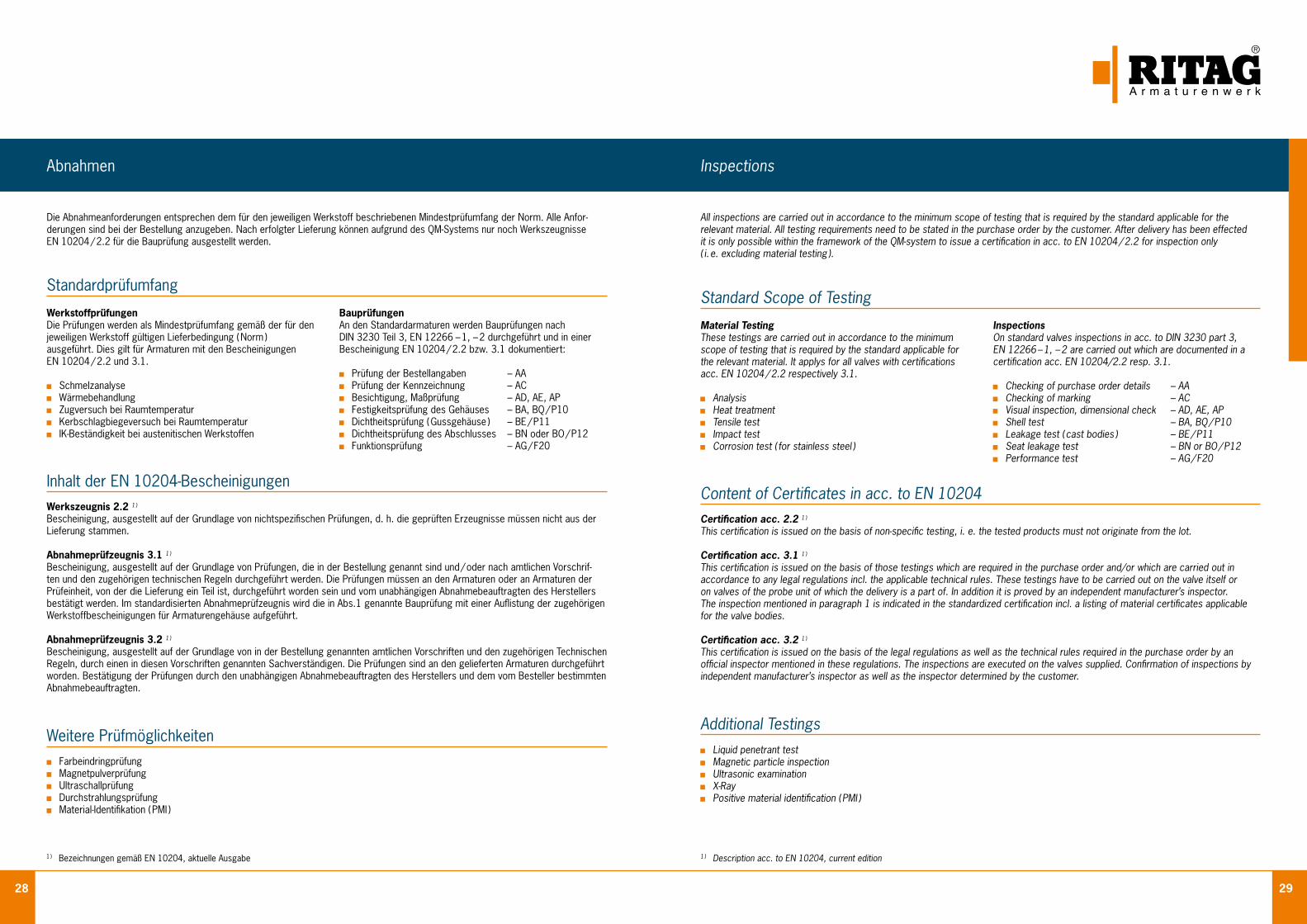
28 29
All inspections are carried out in accordance to the minimum scope of testing that is required by the standard applicable for the relevant material. All testing requirements need to be stated in the purchase order by the customer. After delivery has been effected it is only possible within the framework of the QM-system to issue a certification in acc. to EN 10204 / 2.2 for inspection only ( i. e. excluding material testing ).
Inspections
InspectionsOn standard valves inspections in acc. to DIN 3230 part 3, EN 12266 – 1, – 2 are carried out which are documented in a certification acc. EN 10204/2.2 resp. 3.1.
Checking of purchase order details – AA Checking of marking – AC Visual inspection, dimensional check – AD, AE, AP Shell test – BA, BQ / P10 Leakage test ( cast bodies ) – BE / P11 Seat leakage test – BN or BO / P12 Performance test – AG / F20
Material TestingThese testings are carried out in accordance to the minimum scope of testing that is required by the standard applicable for the relevant material. It applys for all valves with certifications acc. EN 10204 / 2.2 respectively 3.1.
Analysis Heat treatment Tensile test Impact test Corrosion test ( for stainless steel )
1 ) Description acc. to EN 10204, current edition
Standard Scope of Testing
Content of Certificates in acc. to EN 10204Certification acc. 2.2 1 ) This certification is issued on the basis of non-specific testing, i. e. the tested products must not originate from the lot. Certification acc. 3.1 1 )
This certification is issued on the basis of those testings which are required in the purchase order and/or which are carried out in accordance to any legal regulations incl. the applicable technical rules. These testings have to be carried out on the valve itself or on valves of the probe unit of which the delivery is a part of. In addition it is proved by an independent manufacturer’s inspector. The inspection mentioned in paragraph 1 is indicated in the standardized certification incl. a listing of material certificates applicable for the valve bodies. Certification acc. 3.2 1 )
This certification is issued on the basis of the legal regulations as well as the technical rules required in the purchase order by an official inspector mentioned in these regulations. The inspections are executed on the valves supplied. Confirmation of inspections byindependent manufacturer’s inspector as well as the inspector determined by the customer.
Additional Testings Liquid penetrant test Magnetic particle inspection Ultrasonic examination X-Ray Positive material identification ( PMI )
Die Ab nahmeanforderungen entsprechen dem für den jeweiligen Werkstoff beschriebenen Mindestprüfumfang der Norm. Alle Anfor-derungen sind bei der Bestellung anzugeben. Nach erfolgter Lieferung können aufgrund des QM-Systems nur noch Werkszeugnisse EN 10204 / 2.2 für die Bauprüfung ausgestellt werden.
Abnahmen
BauprüfungenAn den Standardarmaturen werden Bauprüfungen nach DIN 3230 Teil 3, EN 12266 – 1, – 2 durchgeführt und in einer Bescheinigung EN 10204 / 2.2 bzw. 3.1 dokumentiert:
Prüfung der Bestellangaben – AA Prüfung der Kennzeichnung – AC Besichtigung, Maßprüfung – AD, AE, AP Festigkeitsprüfung des Gehäuses – BA, BQ / P10 Dichtheitsprüfung ( Gussgehäuse ) – BE / P11 Dichtheitsprüfung des Abschlusses – BN oder BO / P12 Funktionsprüfung – AG / F20
WerkstoffprüfungenDie Prüfungen werden als Mindestprüfumfang gemäß der für den jeweiligen Werkstoff gültigen Lieferbedingung ( Norm ) aus ge führt. Dies gilt für Armaturen mit den Bescheinigungen EN 10204 / 2.2 und 3.1. Schmelzanalyse Wärmebehandlung Zugversuch bei Raumtemperatur Kerbschlagbiegeversuch bei Raumtemperatur IK-Beständigkeit bei austenitischen Werkstoffen
1 ) Bezeichnungen gemäß EN 10204, aktuelle Ausgabe
Standardprüfumfang
Inhalt der EN 10204-BescheinigungenWerkszeugnis 2.2 1 ) Bescheinigung, ausgestellt auf der Grundlage von nichtspezifischen Prüfungen, d. h. die geprüften Erzeugnisse müssen nicht aus der Lieferung stammen. Abnahmeprüfzeugnis 3.1 1 )
Bescheinigung, ausgestellt auf der Grundlage von Prüfungen, die in der Bestellung genannt sind und / oder nach amtlichen Vorschrif-ten und den zugehörigen technischen Regeln durchgeführt werden. Die Prüfungen müssen an den Armaturen oder an Armaturen der Prüfeinheit, von der die Lieferung ein Teil ist, durchgeführt worden sein und vom unabhängigen Abnahmebeauftragten des Herstellers bestätigt werden. Im standardisierten Abnahmeprüfzeugnis wird die in Abs.1 genannte Bauprüfung mit einer Auflistung der zugehörigen Werkstoffbescheinigungen für Armaturengehäuse aufgeführt.
Abnahmeprüfzeugnis 3.2 1 )
Bescheinigung, ausgestellt auf der Grundlage von in der Bestellung genannten amtlichen Vorschriften und den zugehörigen Technischen Regeln, durch einen in diesen Vorschriften genannten Sachverständigen. Die Prüfungen sind an den gelieferten Armaturen durchgeführt worden. Bestätigung der Prüfungen durch den unabhängigen Abnahmebeauftragten des Herstellers und dem vom Besteller bestimmten Abnahmebeauftragten.
Weitere Prüfmöglichkeiten Farbeindringprüfung Magnetpulverprüfung Ultraschallprüfung Durchstrahlungsprüfung Material-Identifikation ( PMI )
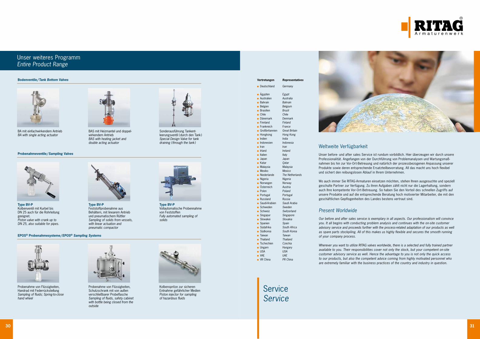
30 31
Weltweite VerfügbarkeitUnser before - und after sales Service ist rundum vorbildlich. Hier überzeugen wir durch unsere Professionalität. Angefangen von der Durchführung von Problemanalysen und Wartungsmaß- nahmen bis hin zur Vor - Ort - Betreuung und natürlich der prozessbezogenen Anpassung unserer Produkte sowie deren entsprechende Ersatzteilbevorratung. All das macht uns hoch flexibel und sichert den reibungslosen Ablauf in Ihrem Unternehmen.
Wo auch immer Sie RITAG - Armaturen einsetzen möchten, stehen Ihnen ausgesuchte und speziell geschulte Partner zur Verfügung. Zu ihren Aufgaben zählt nicht nur die Lagerhaltung, sondern auch Ihre kompetente Vor - Ort - Betreuung. So haben Sie den Vorteil des schnellen Zugriffs auf unsere Produkte und auf die entsprechende Beratung hoch motivierter Mitarbeiter, die mit den geschäftlichen Gepflogenheiten des Landes bestens vertraut sind.
Present WorldwideOur before and after sales service is exemplary in all aspects. Our professionalism will convince you. It all begins with conducting problem analysis and continues with the on-site customer advisory service and proceeds further with the process-related adaptation of our products as well as spare parts stockpiling. All of this makes us highly flexible and secures the smooth running of your company process.
Wherever you want to utilize RITAG valves worldwide, there is a selected and fully trained partner available to you. Their responsibilities cover not only the stock, but your competent on-site customer advisory service as well. Hence the advantage to you is not only the quick access to our products, but also the competent advice coming from highly motivated personnel who are extremely familiar with the business practices of the country and industry in question.
ServiceService
Vertretungen Representatives Deutschland Germany
Ägypten Egypt Australien Australia Bahrain Bahrain Belgien Belgium Brasilien Brazil Chile Chile Dänemark Denmark Finnland Finland Frankreich France Großbritannien Great Britain Hongkong Hong Kong Indien India Indonesien Indonesia Iran Iran Irland Ireland Italien Italy Japan Japan Katar Qatar Malaysia Malaysia Mexiko Mexico Niederlande The Netherlands Nigeria Nigeria Norwegen Norway Österreich Austria Polen Poland Portugal Portugal Russland Russia Saudi-Arabien Saudi Arabia Schweden Sweden Schweiz Switzerland Singapur Singapore Slowakei Slovakia Spanien Spain Südafrika South Africa Südkorea South Korea Taiwan Taiwan Thailand Thailand Tschechien Czechia Ungarn Hungary USA USA VAE UAE VR China PR China
Unser weiteres ProgrammEntire Product Range
Bodenventile / Tank Bottom Valves
Probenahmeventile / Sampling Valves
EPOS® Probenahmesysteme / EPOS® Sampling Systems
Probenahme von Flüssigkeiten, Handrad mit FederrückstellungSampling of fluids; Spring-to-close hand wheel
Probenahme von Flüssigkeiten, Schutzschrank mit von außen verschließ barer ProbeflascheSampling of fluids, safety cabinet with bottle being closed from the outside
Kolbenspritze zur sicheren Entnahme gefährlicher MedienPiston injector for sampling of hazardous fluids
Type BV-P Kolbenventil mit Kurbel bis DN 25 auch für die Rohrleitung geeignet.Piston valve with crank up to DN 25, also suitable for pipes.
Type BV-P Feststoffprobenahme aus Behältern, mit linearem Antrieb und pneumatischem Rüttler Sampling of solids from vessels, with li ne ar actuation and pneumatic compactor
Type BV-P Vollautomatische Probennahme von Feststoffen Fully automated sampling of solids
BA mit einfachwirkendem AntriebBA with single acting actuator
BAS mit Heizmantel und doppel- wirkendem AntriebBAS with heating jacket and double acting actuator
Sonderausführung Tankent- leerungsventil ( durch den Tank )Special Design Valve for tank draining ( through the tank )
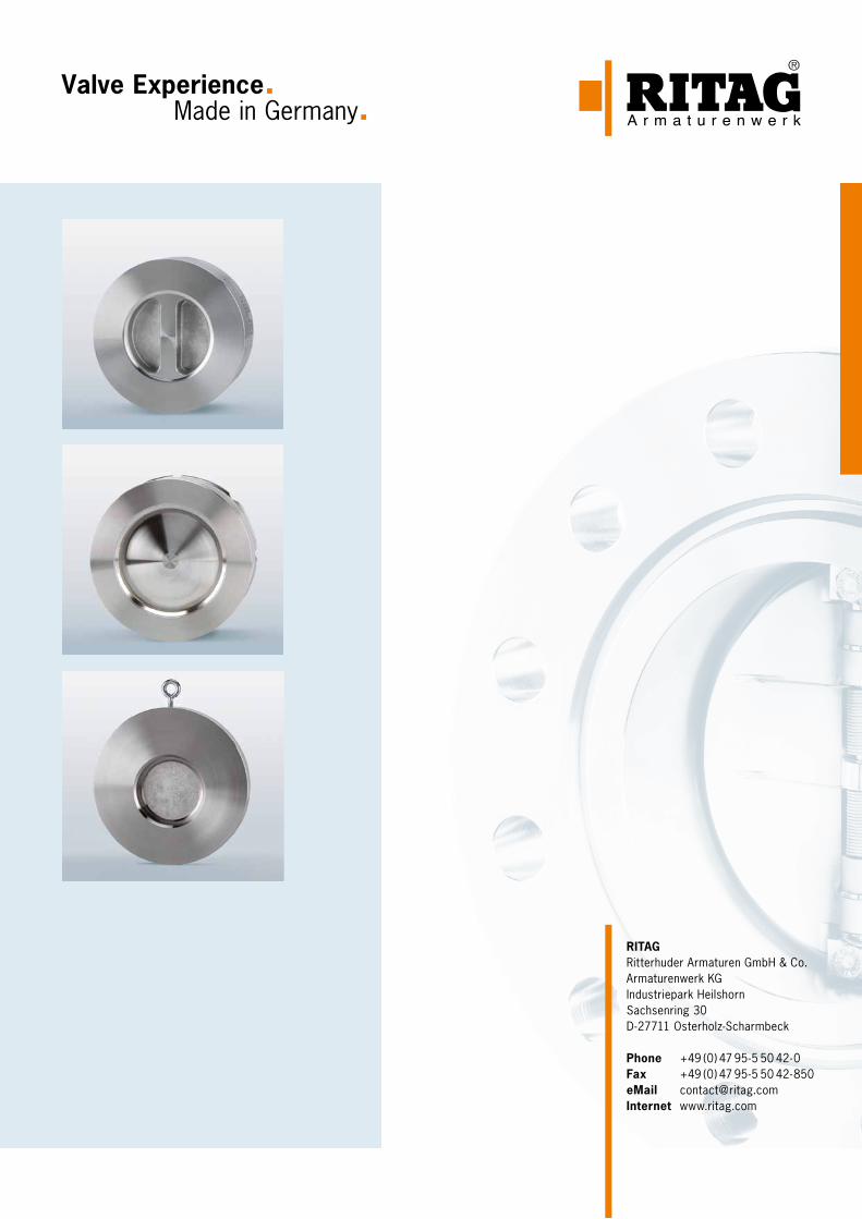
Valve Experience. Made in Germany.
RITAGRitterhuder Armaturen GmbH & Co.Armaturenwerk KGIndustriepark HeilshornSachsenring 30D - 27711 Osterholz-Scharmbeck
Phone +49 (0) 47 95 - 5 50 42 - 0Fax +49 (0) 47 95 - 5 50 42 - 850eMail [email protected] www.ritag.com