Embed Size (px)
Citation preview
Ausgabe / Issue: 2017-03 Technische Änderungen vorbehalten / R
eserve technical changes
1/4
AbschaltventileCutoff Valves ASE & ASG
T
HD/HP
ND/LP
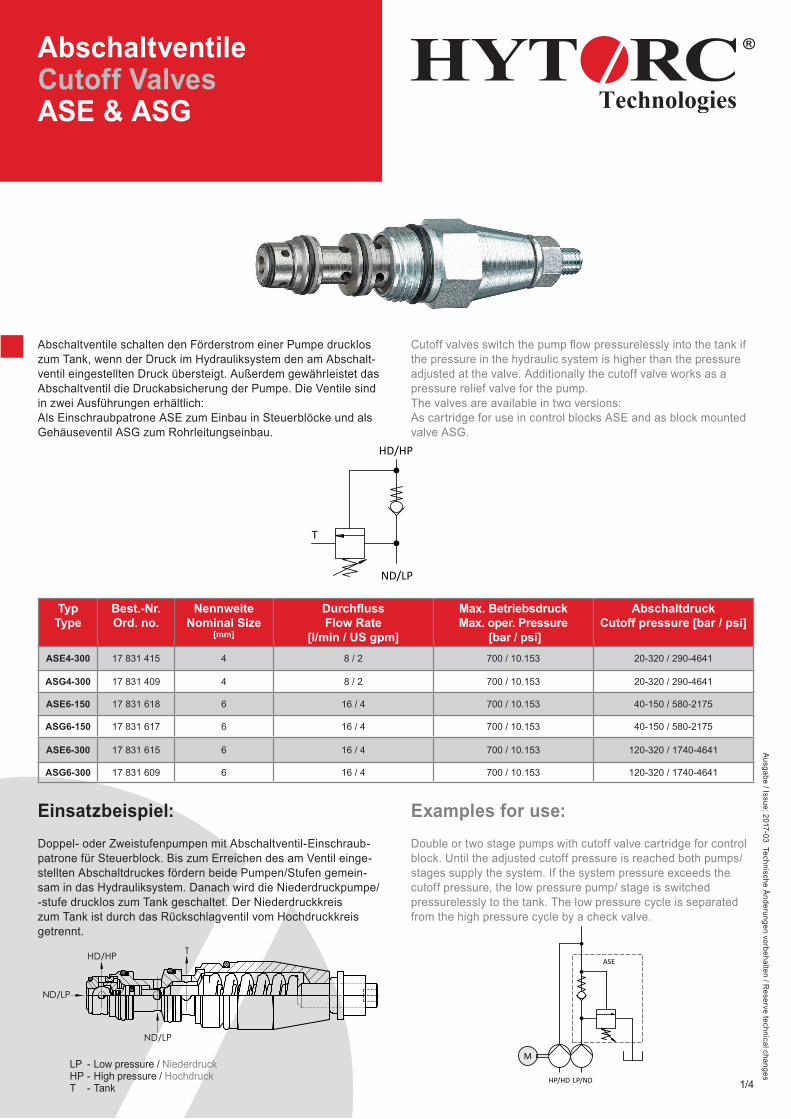
Abschaltventile schalten den Förderstrom einer Pumpe drucklos zum Tank, wenn der Druck im Hydrauliksystem den am Abschalt-ventil eingestellten Druck übersteigt. Außerdem gewährleistet das Abschaltventil die Druckabsicherung der Pumpe. Die Ventile sind in zwei Ausführungen erhältlich:Als Einschraubpatrone ASE zum Einbau in Steuerblöcke und als Gehäuseventil ASG zum Rohrleitungseinbau.
Cutoff valves switch the pump fl ow pressurelessly into the tank if the pressure in the hydraulic system is higher than the pressure adjusted at the valve. Additionally the cutoff valve works as a pressure relief valve for the pump.The valves are available in two versions:As cartridge for use in control blocks ASE and as block mounted valve ASG.
TypType
Best.-Nr. Ord. no.
Nennweite Nominal Size
[mm]
Durchfl ussFlow Rate
[l/min / US gpm]
Max. Betriebsdruck Max. oper. Pressure
[bar / psi]
AbschaltdruckCutoff pressure [bar / psi]
ASE4-300 17 831 415 4 8 / 2 700 / 10.153 20-320 / 290-4641
ASG4-300 17 831 409 4 8 / 2 700 / 10.153 20-320 / 290-4641
ASE6-150 17 831 618 6 16 / 4 700 / 10.153 40-150 / 580-2175
ASG6-150 17 831 617 6 16 / 4 700 / 10.153 40-150 / 580-2175
ASE6-300 17 831 615 6 16 / 4 700 / 10.153 120-320 / 1740-4641
ASG6-300 17 831 609 6 16 / 4 700 / 10.153 120-320 / 1740-4641
HD T
ND
A
A
(2 : 1)
HD/HP T
ND/LP
ND/LP
>1000÷2000
±1,2±0,8
>400÷1000
±0,5
>120÷400
±0,3
>30÷120
±0,2
>6÷30
±0,1
÷6
Werkstoff: Maßstab:
Hydraulik GmbHAm Leveloh 15bD-45549 Sprockhövel
Gewicht:
ISO 2768 mKFreimaßtoleranzen
Für diese Zeichnungbehalten wir uns alle
Rechte vor.( DIN 34 )
Paßmaß Abmaße
Bearb.:Datum Name
Gepr.:
Geänd.:Norm:
17 831 409
12.02.2016 Schleiter
1/1
1:1
Gehäuseventil ASG 4-300
Blatt
0.3 kg
GrößeA4
LP/NDHP/HD
M
ASE
Einsatzbeispiel:Doppel- oder Zweistufenpumpen mit Abschaltventil-Einschraub-patrone für Steuerblock. Bis zum Erreichen des am Ventil einge-stellten Abschaltdruckes fördern beide Pumpen/Stufen gemein-sam in das Hydrauliksystem. Danach wird die Niederdruckpumpe/ -stufe drucklos zum Tank geschaltet. Der Niederdruckkreis zum Tank ist durch das Rückschlagventil vom Hochdruckkreis getrennt.
Examples for use:Double or two stage pumps with cutoff valve cartridge for control block. Until the adjusted cutoff pressure is reached both pumps/ stages supply the system. If the system pressure exceeds the cutoff pressure, the low pressure pump/ stage is switched pressurelessly to the tank. The low pressure cycle is separated from the high pressure cycle by a check valve.
LP - Low pressure / NiederdruckHP - High pressure / HochdruckT - Tank
Ausgabe / Issue: 2017-03 Technische Änderungen vorbehalten / R
eserve technical changes
2/4
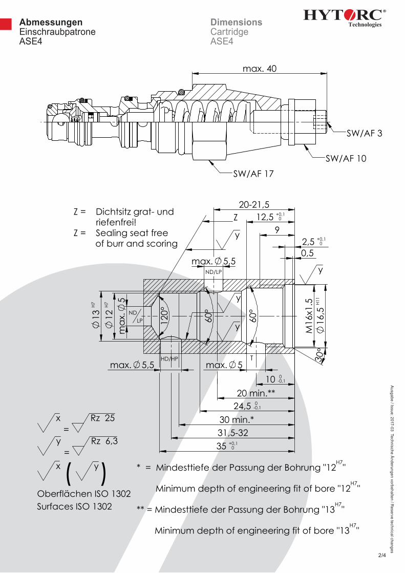
AbmessungenEinschraubpatrone ASE4
DimensionsCartridge ASE4
x =
Rz 25
y =
Rz 6,3
x (
y)Oberflächen ISO 1302Surfaces ISO 1302
C
C
max. 40
SW/AF 3
SW/AF 10SW/AF 17
A
A (1 : 1)
B
Schnitt A-A (1 : 1)
Bemaßungen wurden an Aufnahme-borhung von 17 831 415c - ASE4 angepasst
13
H7
max. 5,5
max. 5
M16
x1.5
16,5
H11
60°
30°
0,5
12
H7
max
.5
max. 5,5
60°
2,5 + 0,10
20-21,5
9 12,5 +
0,10
10 -00,1
24,5 -00,1
31,5-32 35 +
0,10
120
°
20 min.**
30 min.*
Z
HD/HP T
ND/LP
NDLP
y
y
y
y
Rz 25 (
Rz 6,3 )
Oberflächen ISO 1302Surfaces ISO 1302
Z = Dichtsitz grat- und riefenfrei!Z = Sealing seat free
of burr and scoring
* = Mindesttiefe der Passung der Bohrung "12H7
"
Minimum depth of engineering fit of bore "12H7
"
** = Mindesttiefe der Passung der Bohrung "13H7
"
Minimum depth of engineering fit of bore "13H7
"
Ausgabe / Issue: 2017-03 Technische Änderungen vorbehalten / R
eserve technical changes
3/4
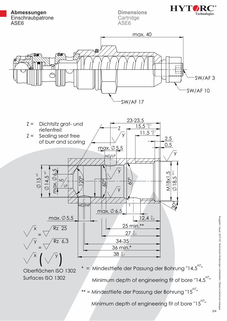
AbmessungenEinschraubpatrone ASE6
DimensionsCartridge ASE6
Rz 25 (
Rz 6,3)Oberflächen ISO 1302Surfaces ISO 1302
x =
Rz 25
y =
Rz 6,3
x (
y)Oberflächen ISO 1302Surfaces ISO 1302
A
A max. 40
SW/AF 3
SW/AF 10
SW/AF 17
B
B
C
Schnitt B-B
M18
x1,5
18,5
H11
30°
max. 6,5 max. 5,5
max. 5,5
max
.6,
5
0,5
14
,5 H7
15 H7
60°
60°
2,5 11,5 +
0,10
15,5 + 0,10
12,4 -00,2
27 -00,1
34-35
38 -00,1
23-23,5
120
°
25 min.*
36 min.**
T
Z
NDLP
HD/HP
ND/LP
x
x
x
x
Z = Dichtsitz grat- und riefenfrei!Z = Sealing seat free
of burr and scoring
* = Mindesttiefe der Passung der Bohrung "14,5H7
"
Minimum depth of engineering fit of bore "14,5H7
"
** = Mindesttiefe der Passung der Bohrung "15H7
"
Minimum depth of engineering fit of bore "15H7
"
Rz 25 (
Rz 6,3)Oberflächen ISO 1302Surfaces ISO 1302
x =
Rz 25
y =
Rz 6,3
x (
y)Oberflächen ISO 1302Surfaces ISO 1302
A
A max. 40
SW/AF 3
SW/AF 10
SW/AF 17
B
B
C
Schnitt B-B
M18
x1,5
18,5
H11
30°
max. 6,5 max. 5,5
max. 5,5
max
.6,
5
0,5
14
,5 H7
15 H7
60°
60°
2,5 11,5 +
0,10
15,5 + 0,10
12,4 -00,2
27 -00,1
34-35
38 -00,1
23-23,5
120
°
25 min.**
36 min.*
T
Z
NDLP
HD/HP
ND/LP
y
y
y
y
Z = Dichtsitz grat- und riefenfrei!Z = Sealing seat free
of burr and scoring
* = Mindesttiefe der Passung der Bohrung "14,5H7
"
Minimum depth of engineering fit of bore "14,5H7
"
** = Mindesttiefe der Passung der Bohrung "15H7
"
Minimum depth of engineering fit of bore "15H7
"
D-45549 Sprockhövel • Kleinbeckstraße 3-17Telefon (02324) 9077-0 • Telefax (02324) [email protected] • www.hytorc-technologies.de
Ausgabe / Issue: 2017-03 Technische Änderungen vorbehalten / R
eserve technical changes
4/4
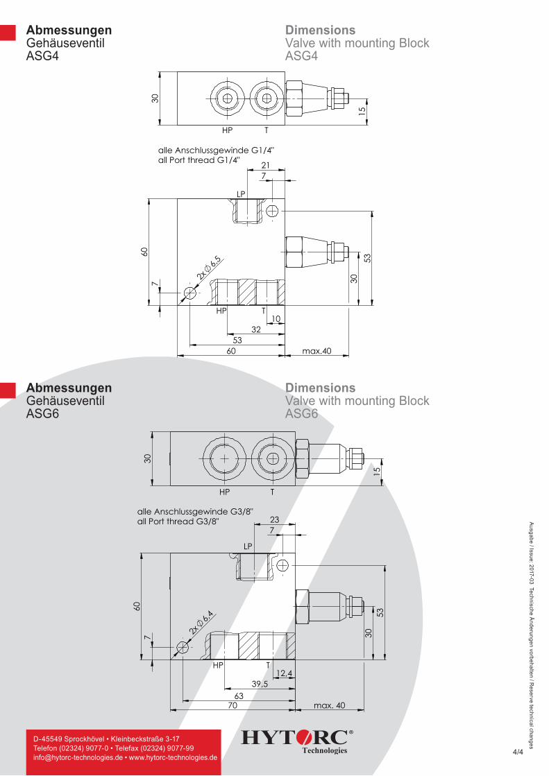
AbmessungenGehäuseventilASG4
DimensionsValve with mounting Block ASG4
7 21
30
53
7
60
10 32
53 60
2x6,5
max.40
HP T
LP
30
15
HP T
Gehäuseventil ASG-4
alle Anschlussgewinde G1/4"all Port thread G1/4"
>1000÷2000
±1,2±0,8
>400÷1000
±0,5
>120÷400
±0,3
>30÷120
±0,2
>6÷30
±0,1
÷6
Werkstoff: Maßstab:
Hydraulik GmbHAm Leveloh 15bD-45549 Sprockhövel
Gewicht:
ISO 2768 mKFreimaßtoleranzen
Für diese Zeichnungbehalten wir uns alle
Rechte vor.( DIN 34 )
Paßmaß Abmaße
Bearb.:Datum Name
Gepr.:
Geänd.:Norm:
17 831 409
12.02.2016 Schleiter
1/1
1:1
Gehäuseventil ASG 4-300
Blatt
0.3 kg
GrößeA4
AbmessungenGehäuseventilASG6
DimensionsValve with mounting Block ASG6
7 23
30
53
7
60
12,4 39,5
63 70
2x6,4
max. 40
HP T
LP
15
30
HP T
alle Anschlussgewinde G3/8"all Port thread G3/8"
Gehäuseventil ASG-6
>1000÷2000
±1,2±0,8
>400÷1000
±0,5
>120÷400
±0,3
>30÷120
±0,2
>6÷30
±0,1
÷6
Werkstoff: Maßstab:
Hydraulik GmbHAm Leveloh 15bD-45549 Sprockhövel
Gewicht:
ISO 2768 mKFreimaßtoleranzen
Für diese Zeichnungbehalten wir uns alle
Rechte vor.( DIN 34 )
Paßmaß Abmaße
Bearb.:Datum Name
Gepr.:
Geänd.:Norm:
17 831 609
12.02.2016 Schleiter
1/1
1:1
Gehäuseventil ASG 6-300
Blatt
0.4 kg
GrößeA4