Embed Size (px)
Citation preview
Art
-Nr.
150
0018
Ramię teleskopowe
Brazo Telescópico
Telescooparm
Bras téléscopique
Telescopic arm
Teleskoparm

1
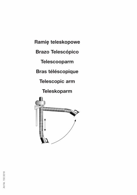
1. Allgemeine Informationen• Lieferung: Der Teleskoparm wird montagefertig geliefert.• Erforderliche Unterkonstruktion: Montieren Sie den Teleskoparm nur an tragfähige Unterkon-
struktionen und befestigen Sie ihn mit entsprechenden Dübeln bzw. durchgehende Schrauben.• Ein-Aus-Schalter und Arbeitsleuchte: Beim Einbau einer Arbeitsleuchte oder eines Ein-Aus-
Schalters zum Einbau in die Absaughaube bitte die entprechende Bedienungsanleitungvor Montage des Teleskoparmes beachten.Aus sicherheitstechnischen Gründen werden sowohl Ein-Aus-Schalter in der Absaughaube, als auch die Arbeitsleuchte mit 24 V Sicherheitskleinspannung betrieben.
2. Montageanleitung2.1 Montage des Teleskoparmes • Die Montagehöhe richtet sich nach den Verhältnissen vor Ort. Im Normalfall wird die
Wandkonsole in einer Höhe von 2,50 m über dem Fußboden montiert. Die Befestigung erfolgtzunächst nur an den beiden oberen Befestigungsbohrungen.
• Hängen Sie das Gegengewicht in das beiliegende Laufrohr und schrauben Sie das Laufrohrmit der Lasche zusammen mit den unteren beiden Bohrungen der Wandkonsole an die Wand(siehe Abbildung 5 auf Seite 8).
• Richten Sie vor dem Festziehen der Schrauben die Wandkonsole aus. • Kontrollieren Sie, ob das Seil vom Gegengewicht über die Führungsrollen läuft und nirgendwo
scheuert.
Abbildung 1, Maßangaben in mm

2
2.2 Verbindung mit einem Wandgerät
2.3 Verbindung zu einer zentralen Rohrleitung
2.3.1 mit einem Zentralventilator
1 Wandgerät2 Bundkragen3 Flanschring4 Schlauchschelle5 Schlauch6 K-Stutzen7 Schnellspannverschluß8 Wandkonsole
Abbildung 2
1 Drosselklappe2 Verbindungsrohr3 K-Stutzen4 Schnellspannverschluß5 Muffe
Abbildung 3
3
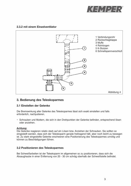
2.3.2 mit einem Einzelventilator
3. Bedienung des Teleskoparmes
3.1 Einstellen der Gelenke
Die Bremswirkung aller Gelenke des Teleskoparmes lässt sich exakt einstellen und falls erforderlich, nachjustieren.
• Schrauben und Muttern, die sich in den Drehpunkten der Gelenke befinden, entsprechend lösen oder anziehen.
Achtung:Die Gelenke reagieren relativ stark auf ein Lösen bzw. Anziehen der Schrauben. Sie sollten so eingestellt werden, dass sich der Teleskoparm gerade freitragend hält, aber noch leicht zu bewegen ist. Zu stark eingestellte Gelenke erschweren eine Positionierung des Teleskoparmes unnötig und können zu Beschädigungen führen.
3.2 Positionieren des Teleskoparmes
Bei Schweißarbeiten ist der Teleskoparm im allgemeinen so zu positionieren, dass sich die Absaughaube in einer Entfernung von 20 - 30 cm schräg oberhalb der Schweißstelle befindet.
1 Verbindungsrohr2 Rückschlagklappe3 Muffe4 Rohrbogen5 K-Stutzen6 Schnellspannverschluß
Abbildung 4
4
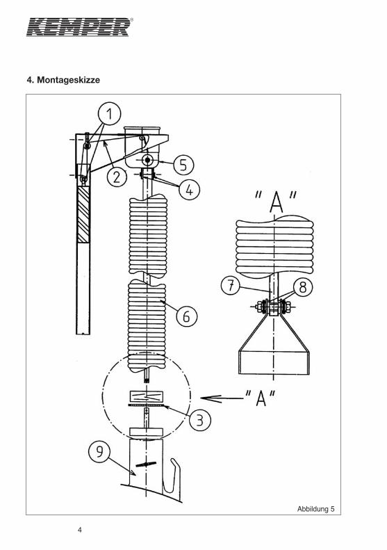
4. Montageskizze
Abbildung 5
5
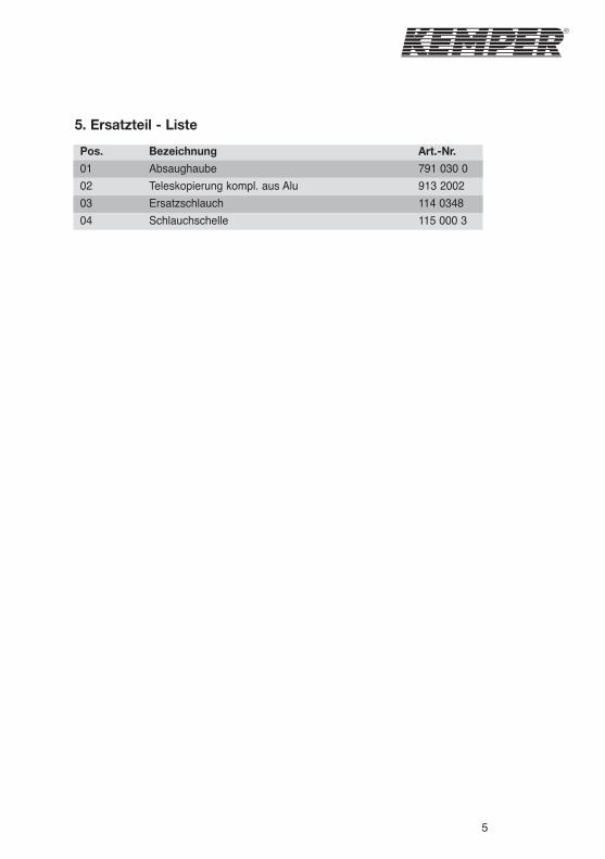
5. Ersatzteil - Liste
Pos.
01
02
03
04
Bezeichnung
Absaughaube
Teleskopierung kompl. aus Alu
Ersatzschlauch
Schlauchschelle
Art.-Nr.
791 030 0
913 2002
114 0348
115 000 3
6
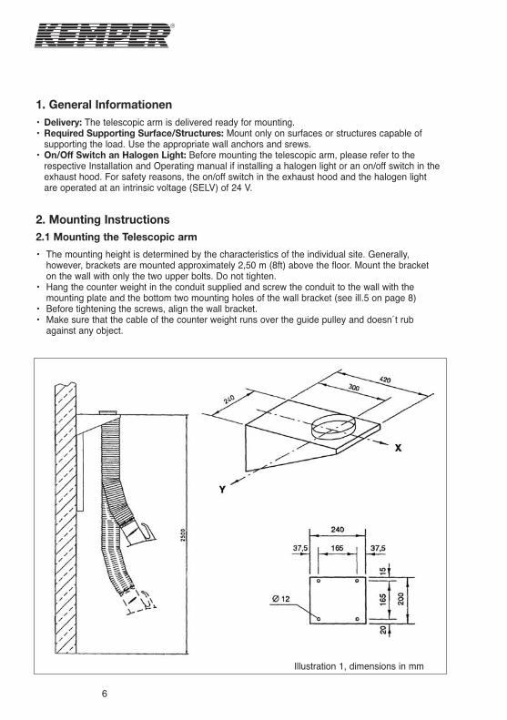
1. General Informationen• Delivery: The telescopic arm is delivered ready for mounting.• Required Supporting Surface/Structures: Mount only on surfaces or structures capable of
supporting the load. Use the appropriate wall anchors and srews.• On/Off Switch an Halogen Light: Before mounting the telescopic arm, please refer to the
respective Installation and Operating manual if installing a halogen light or an on/off switch in theexhaust hood. For safety reasons, the on/off switch in the exhaust hood and the halogen lightare operated at an intrinsic voltage (SELV) of 24 V.
2. Mounting Instructions2.1 Mounting the Telescopic arm
• The mounting height is determined by the characteristics of the individual site. Generally,however, brackets are mounted approximately 2,50 m (8ft) above the floor. Mount the bracketon the wall with only the two upper bolts. Do not tighten.
• Hang the counter weight in the conduit supplied and screw the conduit to the wall with themounting plate and the bottom two mounting holes of the wall bracket (see ill.5 on page 8)
• Before tightening the screws, align the wall bracket.• Make sure that the cable of the counter weight runs over the guide pulley and doesn´t rub
against any object.
Illustration 1, dimensions in mm
7
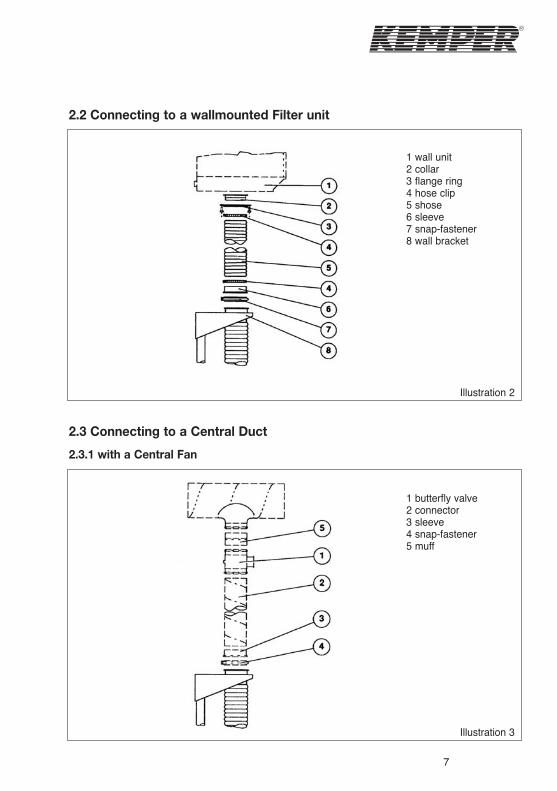
2.2 Connecting to a wallmounted Filter unit
2.3 Connecting to a Central Duct
2.3.1 with a Central Fan
1 wall unit2 collar3 flange ring4 hose clip5 shose6 sleeve7 snap-fastener8 wall bracket
Illustration 2
1 butterfly valve2 connector3 sleeve4 snap-fastener5 muff
Illustration 3
8
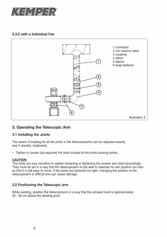
2.3.2 with a Individual Fan
3. Operating the Telescopic Arm
3.1 Installing the Joints
The extent of brading for all the joints in the telescopicarms can be adjusted exactly, and if needed, readjusted.
• Tighten or loosen (as required) the bolts located at the joints pivoting points.
CAUTION:The joints are very sensitive to eighter loosening or tightening the screws and react accordingly.They must be set in a way that the telescopicarm is just able to maintain its own position but alsoso that it is still easy to move. If the joints are fastened too tight, changing the position of thetelescopicarm is difficult and can cause damage.
3.2 Positioning the Telescopic arm
While welding, position the telescopicarm in a way that the exhaust hood is approximately 20 - 30 cm above the welding point.
1 connector2 non returne valve3 coupling4 elbow5 sleeve6 snap-fastener
Illustration 4
9
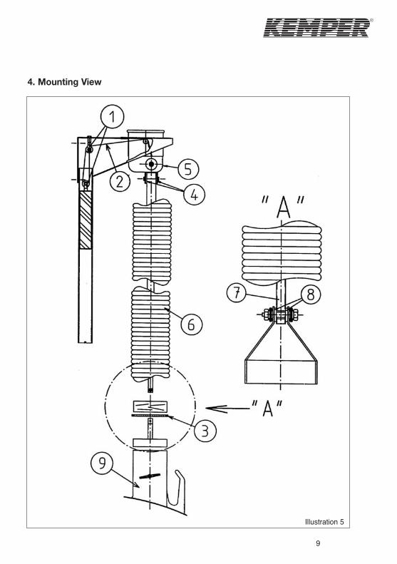
4. Mounting View
Illustration 5
10
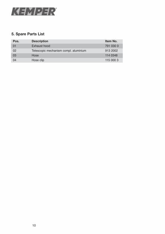
5. Spare Parts List
Pos.
01
02
03
04
Description
Exhaust hood
Telescopic mechanism compl. aluminium
Hose
Hose clip
Item No.
791 030 0
913 2002
114 0348
115 000 3
11
1. Informations générales• Livraisun: Le bras téléscopique est livré prêt au montage.• Supports: Les bras doivent être montés sur des supports solides, à l´aide de vis et de chevilles
appro-priéeces.• Interrupteur marche-arrêt et éclairage: Avant de monter le bras, consulter les notices
correspondantes pour l´éclairage et l´interrupteur avant de les brancher. Pour des raisons desécurité, l´éclairage et l´ínterrupteur marche-arrêt fonctionnent sous une tension de 24 V.
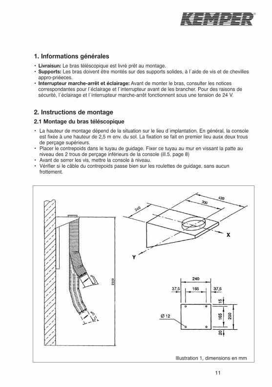
2. Instructions de montage2.1 Montage du bras téléscopique
• La hauteur de montage dépend de la situation sur le lieu d´implantation. En général, la consoleest fixée à une hauteur de 2,5 m env. du sol. La fixation se fait en premier lieu ausx deux trousde perçage supérieurs.
• Placer le contrepoids dans le tuyau de guidage. Fixer ce tuyau au mur en vissant la patte auniveau des 2 trous de perçage inférieurs de la console (ill.5, page 8)
• Avant de serrer les vis, mettre la console à niveau.• Vérifier si le câble du contrepoids passe bien sur les roulettes de guidage, sans aucun
frottement.
Illustration 1, dimensions en mm
12
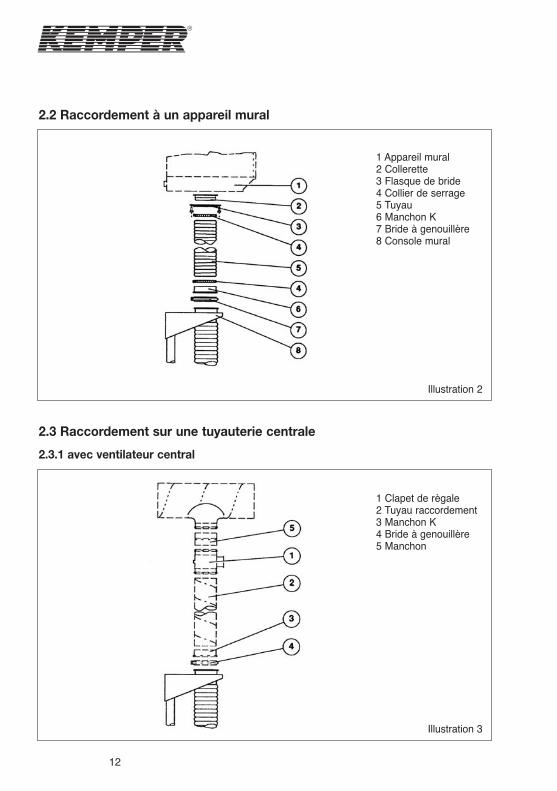
2.2 Raccordement à un appareil mural
2.3 Raccordement sur une tuyauterie centrale
2.3.1 avec ventilateur central
1 Appareil mural2 Collerette3 Flasque de bride4 Collier de serrage5 Tuyau6 Manchon K7 Bride à genouillère8 Console mural
1 Clapet de règale2 Tuyau raccordement3 Manchon K4 Bride à genouillère5 Manchon
Illustration 2
Illustration 3
13
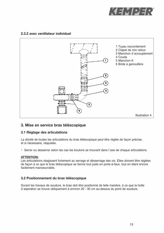
2.3.2 avec ventilateur individuel
3. Mise en service bras téléscopique
3.1 Réglage des articulations
La dûreté de toutes les articulations du bras téléscopique peut être règlée de façon précise, et si nécessaire, réajustée.
• Serrer ou desserrer selon les cas les boulons se trouvant dans l´axe de chaque articulations.
ATTENTION:Les articulations réagissent fortement au serrage et désserrage des vis. Elles doivent être règléesde façon à ce que le bras téléscopique se tienne tout juste en porte-à-faux, tout en étant encorefacilement manoeuvrable.
3.2 Positionnement du bras téléscopique
Durant les travaux de soudure, le bras doit être positionné de telle manière, à ce que la hotted´aspiration se trouve obliquement à environ 20 - 30 cm au-dessus du point de soudure.
1 Tuyau raccordement2 Clapet de non retour3 Manchon d`accouplement4 Coude5 Manchon K6 Bride à genouillère
Illustration 4
14
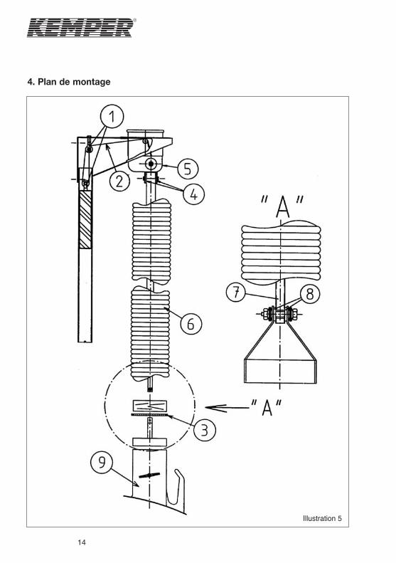
4. Plan de montage
Illustration 5
15
5. Liste des piéces de rechange
Pos.
01
02
03
04
Article
Hotte d´aspiration
Partie téléscopique compléte, alu
Tuyau flexible
Collier de serrage
Réf.
791 030 0
913 2002
114 0348
115 000 3
16
1. Allgemene informatie• Leveringsomvang: De telescooparm wordt compleet en klaar voor montage geleverd.• Vereiste draagconstructie: Monteer de telescooparm op een deugdelijke manier en schroef
de arm met geschikte bouten of schroeven vast.• Aan-uit-schakelaar en verlichtingsset: Voor de inbouw van een verlichtingsset of een
aan-uitschakelaar in de afzuigkap verwijzen wij u naar de desbetreffende bedieningshandleiding voor de montage van de telescooparm.Voor veiligheidsdoeleinden worden zowel de aan-uit-schakelaar in de afzuigkap als de verlichtingsset met een 24 V veiligheidszekering voorzien.
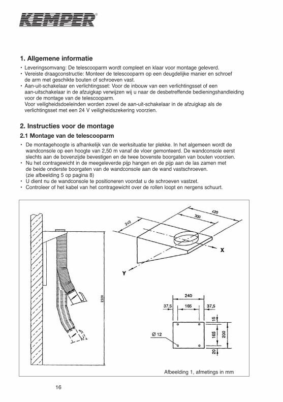
2. Instructies voor de montage2.1 Montage van de telescooparm• De montagehoogte is afhankelijk van de werksituatie ter plekke. In het algemeen wordt de
wandconsole op een hoogte van 2,50 m vanaf de vloer gemonteerd. De wandconsole eerst slechts aan de bovenzijde bevestigen en de twee bovenste boorgaten van bouten voorzien.
• Nu het contragewicht in de meegeleverde pijp hangen en de pijp aan de las zamen met de beide onderste boorgaten van de wandconsole aan de wand vastschroeven. (zie afbeelding 5 op pagina 8)
• U dient nu de wandconsole te positioneren voordat u de schroeven vastzet. • Controleer of het kabel van het contragewicht over de rollen loopt en nergens schuurt.
Afbeelding 1, afmetings in mm
17
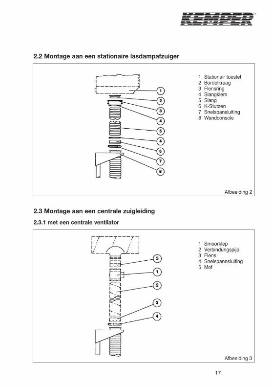
2.2 Montage aan een stationaire lasdampafzuiger
2.3 Montage aan een centrale zuigleiding
2.3.1 met een centrale ventilator
1 Stationair toestel2 Bordelkraag3 Flensring4 Slangklem5 Slang6 K-Stutzen7 Snelspansluiting8 Wandconsole
Afbeelding 2
1 Smoorklep2 Verbindungspijp3 Flens4 Snelspannsluiting5 Mof
Afbeelding 3
18
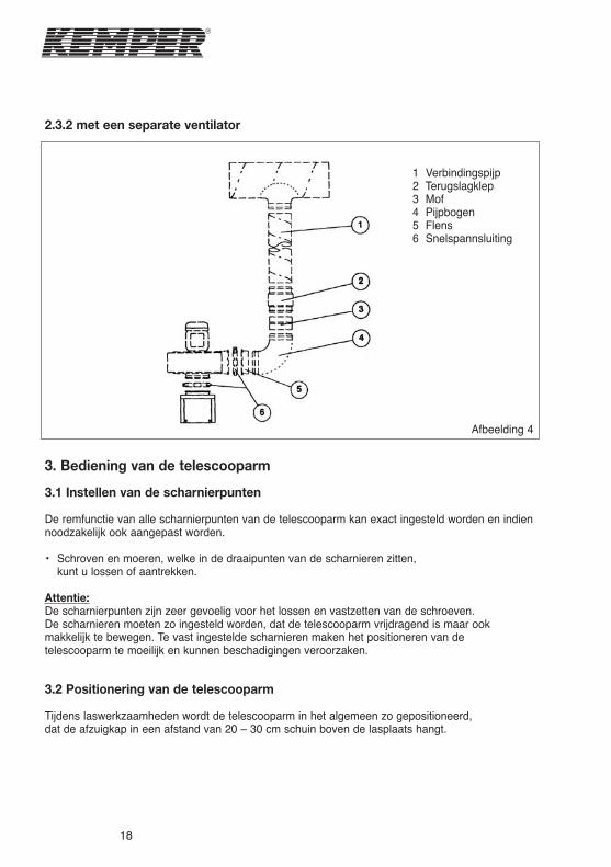
2.3.2 met een separate ventilator
3. Bediening van de telescooparm
3.1 Instellen van de scharnierpunten
De remfunctie van alle scharnierpunten van de telescooparm kan exact ingesteld worden en indiennoodzakelijk ook aangepast worden.
• Schroven en moeren, welke in de draaipunten van de scharnieren zitten, kunt u lossen of aantrekken.
Attentie:De scharnierpunten zijn zeer gevoelig voor het lossen en vastzetten van de schroeven. De scharnieren moeten zo ingesteld worden, dat de telescooparm vrijdragend is maar ook makkelijk te bewegen. Te vast ingestelde scharnieren maken het positioneren van de telescooparm te moeilijk en kunnen beschadigingen veroorzaken.
3.2 Positionering van de telescooparm
Tijdens laswerkzaamheden wordt de telescooparm in het algemeen zo gepositioneerd, dat de afzuigkap in een afstand van 20 – 30 cm schuin boven de lasplaats hangt.
1 Verbindingspijp2 Terugslagklep3 Mof4 Pijpbogen5 Flens6 Snelspannsluiting
Afbeelding 4

19
4. Montagetekening
Afbeelding 5
20
5. Lijst van reserveonderdelen
Pos.
01
02
03
04
Beschrijving
Afzuigkap
Telescoopeering compl., aluminium
Reserveslang
Slangklem
Art.-Nr.
791 030 0
913 2002
114 0348
115 000 3
21
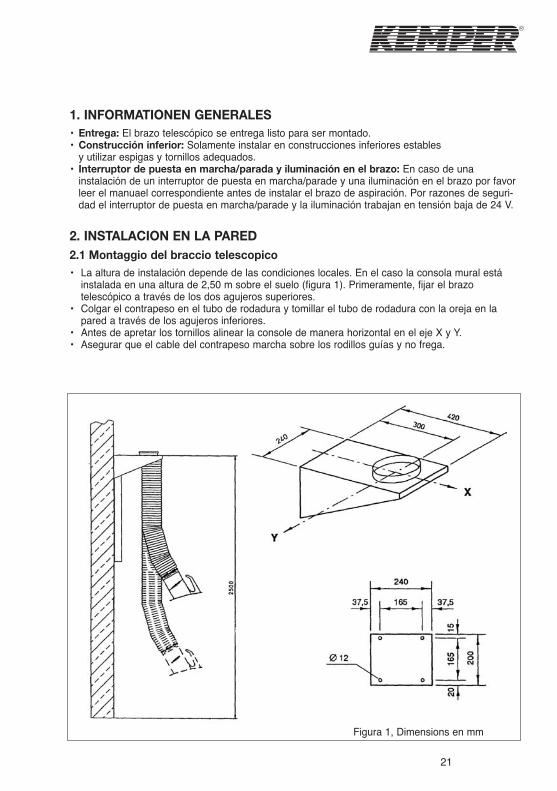
1. INFORMATIONEN GENERALES• Entrega: El brazo telescópico se entrega listo para ser montado.• Construcción inferior: Solamente instalar en construcciones inferiores estables
y utilizar espigas y tornillos adequados.• Interruptor de puesta en marcha/parada y iluminación en el brazo: En caso de una
instalación de un interruptor de puesta en marcha/parade y una iluminación en el brazo por favor leer el manuael correspondiente antes de instalar el brazo de aspiración. Por razones de seguri-dad el interruptor de puesta en marcha/parade y la iluminación trabajan en tensión baja de 24 V.
2. INSTALACION EN LA PARED2.1 Montaggio del braccio telescopico• La altura de instalación depende de las condiciones locales. En el caso la consola mural está
instalada en una altura de 2,50 m sobre el suelo (figura 1). Primeramente, fijar el brazo telescópico a través de los dos agujeros superiores.
• Colgar el contrapeso en el tubo de rodadura y tomillar el tubo de rodadura con la oreja en la pared a través de los agujeros inferiores.
• Antes de apretar los tornillos alinear la console de manera horizontal en el eje X y Y.• Asegurar que el cable del contrapeso marcha sobre los rodillos guías y no frega.
Figura 1, Dimensions en mm
22
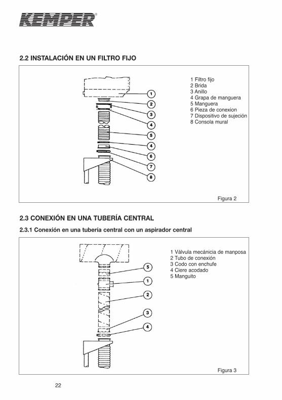
2.2 INSTALACIÓN EN UN FILTRO FIJO
2.3 CONEXIÓN EN UNA TUBERÍA CENTRAL
2.3.1 Conexión en una tubería central con un aspirador central
1 Filtro fijo2 Brida3 Anillo4 Grapa de manguera5 Manguera6 Pieza de conexion7 Dispositivo de sujeción8 Consola mural
Figura 2
1 Válvula mecánicia de manposa2 Tubo de conexión3 Codo con enchufe4 Ciere acodado5 Manguito
Figura 3
23
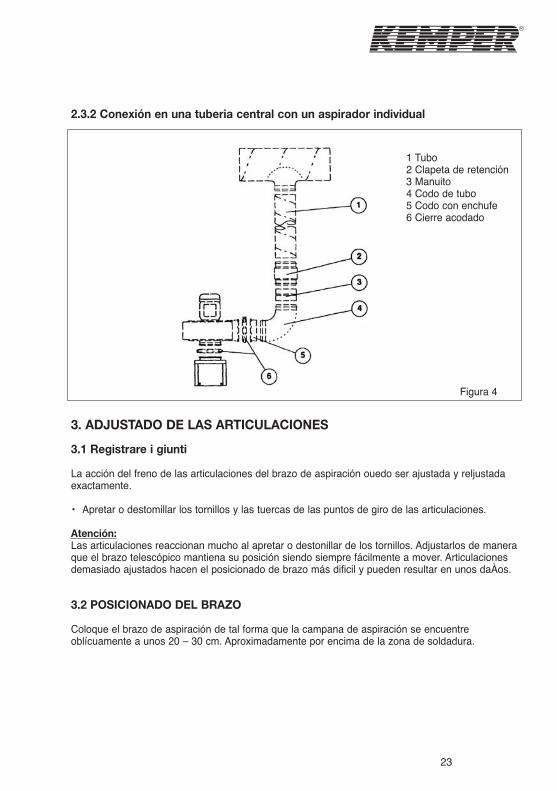
2.3.2 Conexión en una tuberia central con un aspirador individual
3. ADJUSTADO DE LAS ARTICULACIONES
3.1 Registrare i giunti
La acción del freno de las articulaciones del brazo de aspiración ouedo ser ajustada y reljustada exactamente.
• Apretar o destomillar los tornillos y las tuercas de las puntos de giro de las articulaciones.
Atención:Las articulaciones reaccionan mucho al apretar o destonillar de los tornillos. Adjustarlos de manera que el brazo telescópico mantiena su posición siendo siempre fácilmente a mover. Articulaciones demasiado ajustados hacen el posicionado de brazo más dificil y pueden resultar en unos daÀos.
3.2 POSICIONADO DEL BRAZO
Coloque el brazo de aspiración de tal forma que la campana de aspiración se encuentre oblícuamente a unos 20 – 30 cm. Aproximadamente por encima de la zona de soldadura.
1 Tubo2 Clapeta de retención3 Manuito4 Codo de tubo5 Codo con enchufe6 Cierre acodado
Figura 4
24
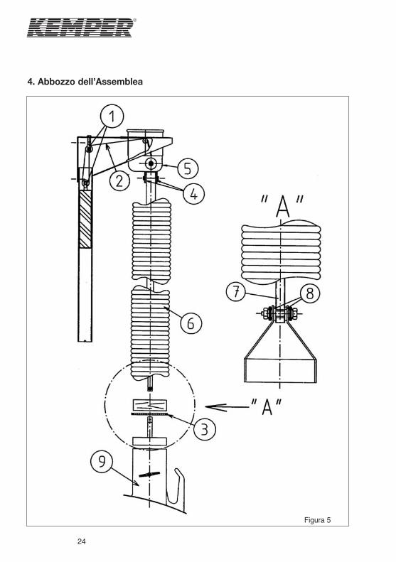
4. Abbozzo dell’Assemblea
Figura 5

25
5. Elenco delle parti di spara
Pos.
01
02
03
04
Modello
Cappuccio dello scarico
Meccanismo telescopico compl. aluminium
Tubo flessible
Clip del tubo flessible
N. art.
791 030 0
913 2002
114 0348
115 000 3
26
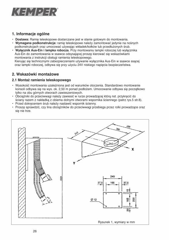
1. Informacje ogólne
• Dostawa: Ramię teleskopowe dostarczane jest w stanie gotowym do montowania.• Wymagana podkonstrukcja: ramię teleskopowe należy zamontować jedynie na nośnych
podkonstrukcjach oraz umocować używając wkładek/kołków lub przedłużonych śrub.• Wyłącznik Aus-Ein i lampka robocza. Przy montowaniu lampki roboczej lub wyłącznika
Aus-Ein do zamontowania w ssawce odsysającej proszę kierować się wskazówkamimontowania z instrukcji obsługi ramienia teleskopowego.Kierując się technicznymi zabezpieczeniami używanie wyłącznika Aus-Ein w ssawce ssącejoraz lampki roboczej, odbywa się przy użyciu 24V niskiego napięcia bezpieczeństwa.
2. Wskazówki montażowe
2.1 Montaż ramienia teleskopowego
• Wysokość montowania uzależniona jest od warunków otoczenia. Standardowo montowaniekonsoli odbywa się na wys. ok. 2,50 m ponad podłożem. Umocowanie odbywa się początkowotylko na obu górnych otworach zawieszeniowych.
• Obciążniki do przeciwwagi należy zawiesić w rurze prowadzącej którą nst. przykręcić dościany razem z nakładką z obiema dolnymi otworami wspornika ściennego (patrz rys.5 str.8).
• Przed dokręceniem śrub należy nastawić wspornik ścienny.• Proszę sprawdzić, czy lina obciążników do przeciwwagi przebiega przez rolki prowadzące oraz
się nie trze.
Rysunek 1, wymiary w mm
27
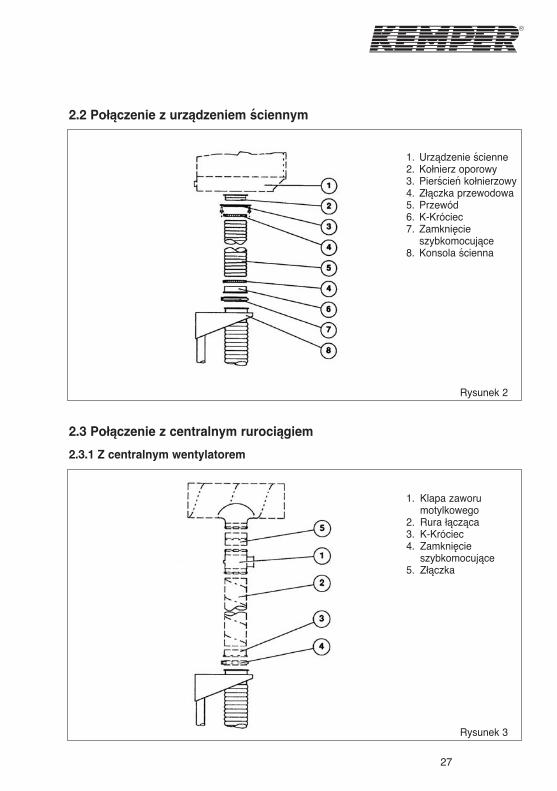
2.2 Połączenie z urządzeniem ściennym
2.3 Połączenie z centralnym rurociągiem
2.3.1 Z centralnym wentylatorem
1. Urządzenie ścienne2. Kołnierz oporowy3. Pierścień kołnierzowy4. Złączka przewodowa5. Przewód6. K-Króciec7. Zamknięcie
szybkomocujące8. Konsola ścienna
Rysunek 2
1. Klapa zaworumotylkowego
2. Rura łącząca3. K-Króciec4. Zamknięcie
szybkomocujące5. Złączka
Rysunek 3
28
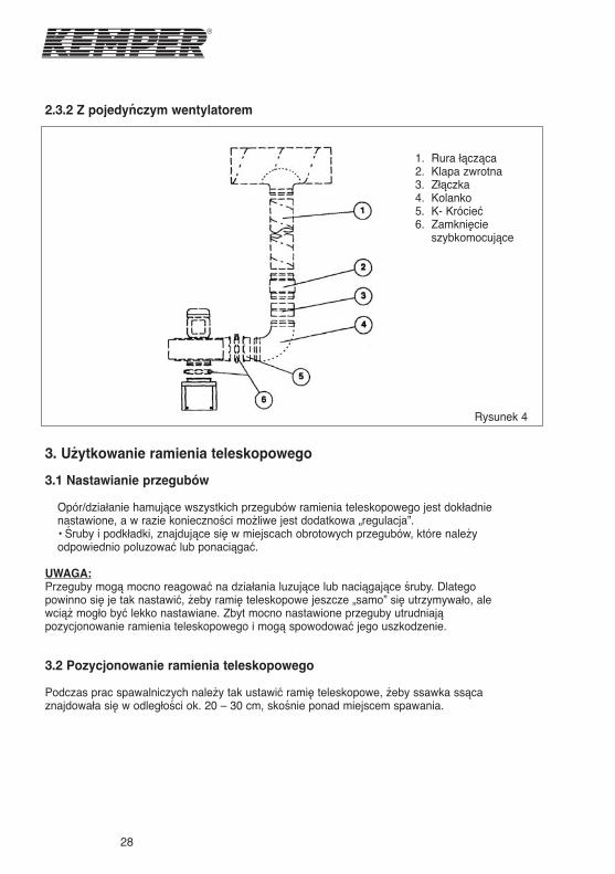
2.3.2 Z pojedyńczym wentylatorem
3. Użytkowanie ramienia teleskopowego
3.1 Nastawianie przegubów
Opór/działanie hamujące wszystkich przegubów ramienia teleskopowego jest dokładnienastawione, a w razie konieczności możliwe jest dodatkowa „regulacja”.• Śruby i podkładki, znajdujące się w miejscach obrotowych przegubów, które należyodpowiednio poluzować lub ponaciągać.
UWAGA:Przeguby mogą mocno reagować na działania luzujące lub naciągające śruby. Dlategopowinno się je tak nastawić, żeby ramię teleskopowe jeszcze „samo” się utrzymywało, alewciąż mogło być lekko nastawiane. Zbyt mocno nastawione przeguby utrudniająpozycjonowanie ramienia teleskopowego i mogą spowodować jego uszkodzenie.
3.2 Pozycjonowanie ramienia teleskopowego
Podczas prac spawalniczych należy tak ustawić ramię teleskopowe, żeby ssawka ssącaznajdowała się w odległości ok. 20 – 30 cm, skośnie ponad miejscem spawania.
1. Rura łącząca2. Klapa zwrotna3. Złączka4. Kolanko5. K- Krócieć6. Zamknięcie
szybkomocujące
Rysunek 4
29
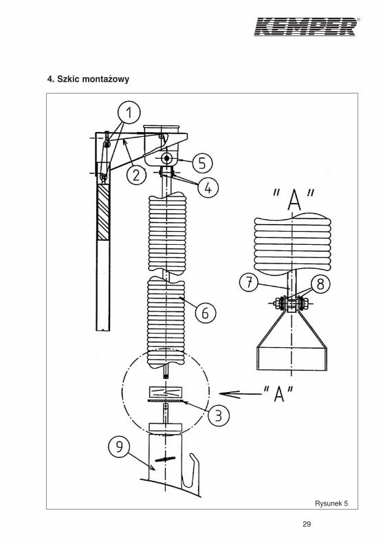
4. Szkic montażowy
Rysunek 5
30
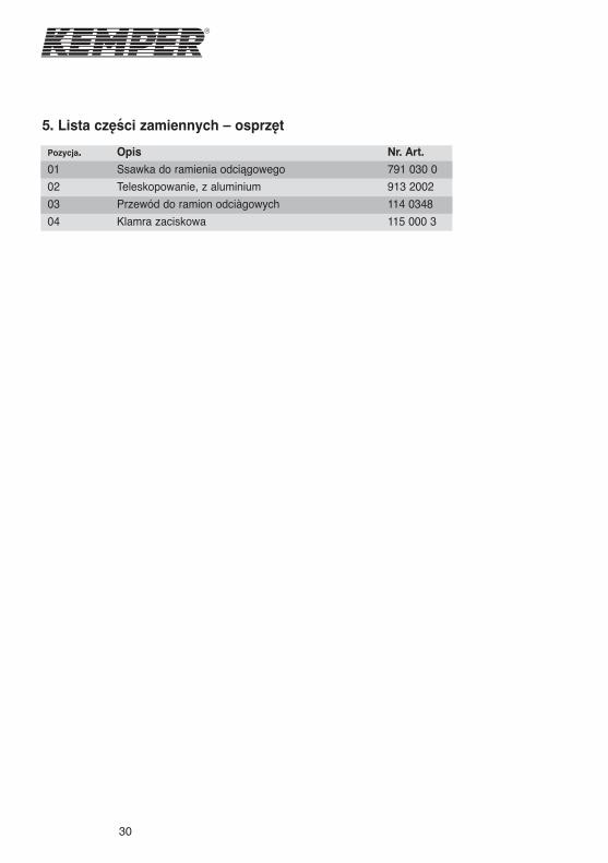
5. Lista części zamiennych – osprzęt
Pozycja.
01
02
03
04
Opis
Ssawka do ramienia odciągowegoTeleskopowanie, z aluminiumPrzewód do ramion odciàgowych
Klamra zaciskowa
Nr. Art.
791 030 0
913 2002
114 0348
115 000 3


Deutschland
KEMPER GmbHVon-Siemens-Str. 20D-48691 VredenTel. +49(0)2564/68-0Fax +49(0)2564/[email protected]
United Kingdom
KEMPER (U.K.) Ltd.Venture Court2 Debdale RoadWellingborough NorthamptonshireNN8 5AATel. +44(0)1327/872909Fax +44(0)1327/[email protected]
España
KEMPER IBÉRICA, S.L.Av. Riera Principal, 8E-08328 Allela/BarcelonaTel. +34(93)5726290Fax +34(93)[email protected]
China
KEMPER Exhaust System(Shanghai) Co. Ltd.No. 14 Building, Xiao-Nan RoadJianghai Industry AreaFengXian DistrictShanghai 201400P.R. of ChinaTel. +86(21)33658991Fax +86(21)37441682
France
KEMPER sàrlZI du RiedF-67590 Schweighouse sur ModerTel. +33(0)388072980Fax +33(0)[email protected]
Nederland
KEMPER B.V.Postbus 83NL-7140 AB GroenloVerkoopkantoorTel. +49(0)2564/68-137Fax +49(0)2564/[email protected]
Česká Republika
KEMPER spol. s r.o.ul. PyšelskáCZ-257 21 Poříčí nad SázavouTel. +420/317 798 000Fax +420/317 798 [email protected]
United States
KEMPER America, Inc.1005 Alderman Dr.Suite 114Alpharetta, GA 30005Tel. 770/4167070Fax 770/[email protected]