Embed Size (px)
Citation preview
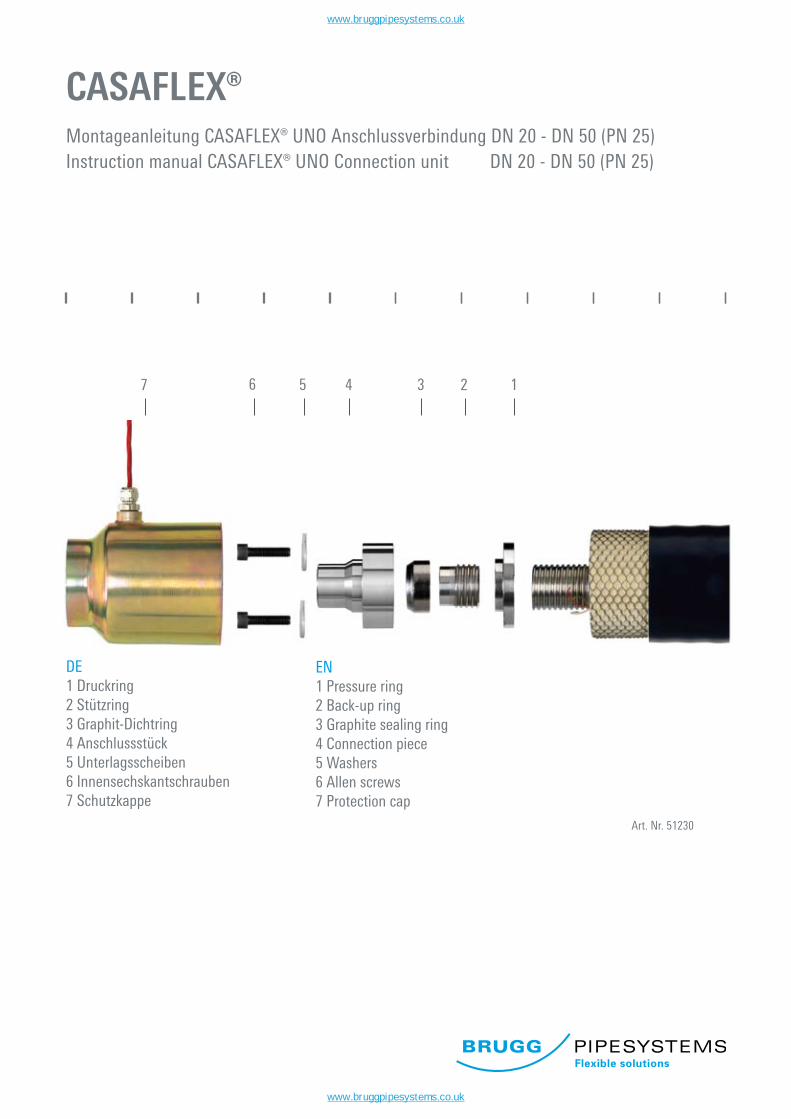
CASAFLEX®Montageanleitung CASAFLEX® UNO Anschlussverbindung DN 20 - DN 50 (PN 25)Instruction manual CASAFLEX® UNO Connection unit DN 20 - DN 50 (PN 25)
Art. Nr. 51230
7 4 3 2 1
DE1 Druckring2 Stützring3 Graphit-Dichtring4 Anschlussstück5 Unterlagsscheiben6 Innensechskantschrauben7 Schutzkappe
EN1 Pressure ring2 Back-up ring3 Graphite sealing ring4 Connection piece5 Washers6 Allen screws7 Protection cap
6 5
www.bruggpipesystems.co.uk
www.bruggpipesystems.co.uk
1. 04. 2009 www.pipesystems.com Tel. +41 56 268 78 78
CASAFLEX® UNO 2
- Tec
hnis
che
Ände
rung
en v
orbe
halte
n - S
ubje
ct to
tech
nica
l cha
nge
-
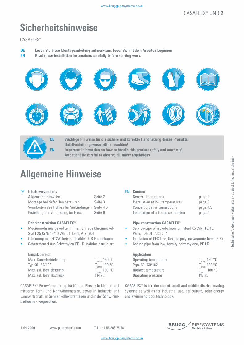
SicherheitshinweiseCASAFLEX®
DE Lesen Sie diese Montageanleitung aufmerksam, bevor Sie mit dem Arbeiten beginnenEN Read these installation instructions carefully before starting work.
DE Wichtige Hinweise für die sichere und korrekte Handhabung dieses Produkts!
Unfallverhütungsvorschriften beachten! EN Important information on how to handle this product safely and correctly! Attention! Be careful to observe all safety regulations
DE Inhaltsverzeichnis Allgemeine Hinweise Seite 2 Montage bei tiefen Temperaturen Seite 3 Verarbeiten des Rohres für Verbindungen Seite 4,5 Erstellung der Verbindung im Haus Seite 6
Rohrkonstruktion CASAFLEX®• Mediumrohr aus gewelltem Innenrohr aus Chromnickel- Stahl X5 CrNi 18/10 WNr. 1.4301, AISI 304• Dämmung aus FCKW-freiem, flexiblen PIR-Hartschaum• Schutzmantel aus Polyethylen PE-LD, nahtlos extrudiert
Einsatzbereich Max. Dauerbetriebstemp. TBmax 160 °C Typ 60+60/182 TBmax 130 °C Max. zul. Betriebstemp. Tmax 180 °C Max. zul. Betriebsdruck PN 25
CASAFLEX®-Fernwärmeleitung ist für den Einsatz in kleinen und mittleren Fern- und Nahwärmenetzen, sowie in Industrie und Landwirtschaft, in Sonnenkollektoranlagen und in der Schwimm-badtechnik vorgesehen.
EN Content General Instructions page 2 Installation at low temperatures page 3 Convert pipe for connections page 4,5 Installation of a house connection page 6
Pipe construction CASAFLEX®• Service-pipe of nickel-chromium steel X5 CrNi 18/10, Wno. 1.4301, AISI 304• Insulation of CFC-free, flexible polyisocyanurate foam (PIR) • Casing pipe from low density polyethylene, PE-LD
Application Operating temperature TBmax 160 °C Type 60+60/182 TBmax 130 °C Highest temperature Tmax 180 °C Operating pressure PN 25
CASAFLEX® is for the use of small and middle district heating systems as well as for industrial use, agriculture, solar energy and swimming pool technology.
Allgemeine Hinweise
x = 50mm
x
www.bruggpipesystems.co.uk
www.bruggpipesystems.co.uk
1. 04. 2009 www.pipesystems.com Tel. +41 56 268 78 78
CASAFLEX® UNO 3
- Tec
hnis
che
Ände
rung
en v
orbe
halte
n - S
ubje
ct to
tech
nica
l cha
nge
-
Montageanleitung
DE Verlegung und Montage von CASAFLEX® Rohren EN Laying and installation of CASAFLEX® pipes
1.DE Verlegung (Skizze) Spannbänder nacheinander von aussen nach innen durchtrennen und Ring im Graben (oder neben dem Graben) abrollen.
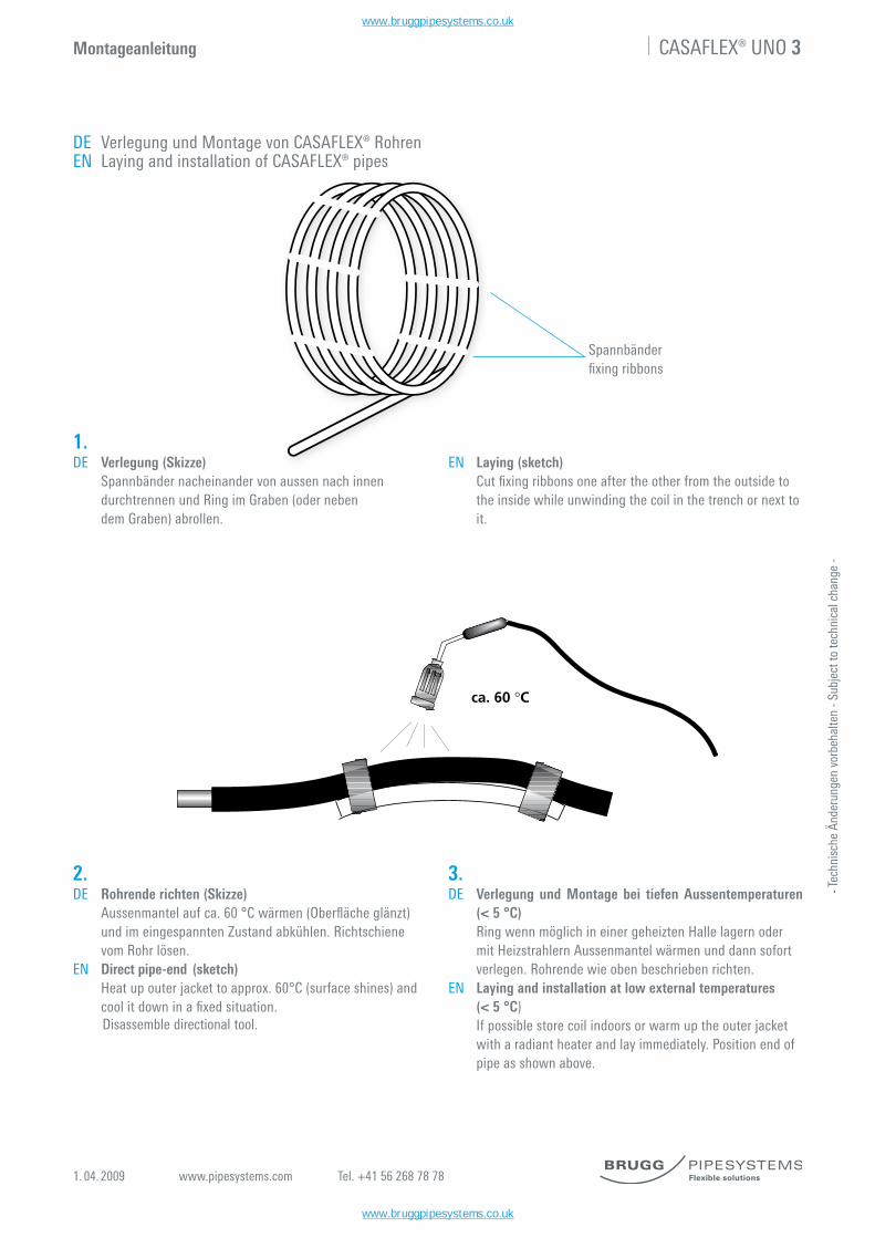
Spannbänderfixingribbons
2.DE Rohrende richten (Skizze) Aussenmantelaufca.60°Cwärmen(Oberflächeglänzt) und im eingespannten Zustand abkühlen. Richtschiene vom Rohr lösen. EN Direct pipe-end (sketch) Heat up outer jacket to approx. 60°C (surface shines) and coolitdowninafixedsituation. Disassemble directional tool.
3.DE Verlegung und Montage bei tiefen Aussentemperaturen
(< 5 °C) Ring wenn möglich in einer geheizten Halle lagern oder mit Heizstrahlern Aussenmantel wärmen und dann sofort verlegen. Rohrende wie oben beschrieben richten.EN Laying and installation at low external temperatures (< 5 °C) If possible store coil indoors or warm up the outer jacket with a radiant heater and lay immediately. Position end of pipe as shown above.
ca. 60 °C
EN Laying (sketch) Cutfixingribbonsoneaftertheotherfromtheoutsideto the inside while unwinding the coil in the trench or next to it.
www.bruggpipesystems.co.uk
www.bruggpipesystems.co.uk
1. 04. 2009 www.pipesystems.com Tel. +41 56 268 78 78
CASAFLEX® UNO 4
- Tec
hnis
che
Ände
rung
en v
orbe
halte
n - S
ubje
ct to
tech
nica
l cha
nge
-
Montageanleitung
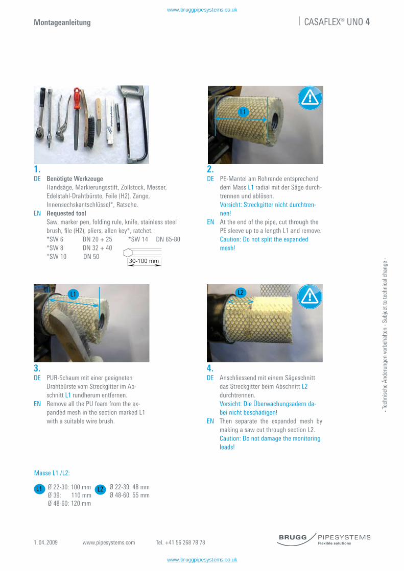
1.DE Benötigte Werkzeuge Handsäge, Markierungsstift, Zollstock, Messer, Edelstahl-Drahtbürste, Feile (H2), Zange, Innensechskantschlüssel*, Ratsche.EN Requested tool Saw, marker pen, folding rule, knife, stainless steel brush,file(H2),pliers,allenkey*,ratchet. *SW 6 DN 20 + 25 *SW 14 DN 65-80 *SW 8 DN 32 + 40 *SW 10 DN 50
3.DE PUR-Schaum mit einer geeigneten
Drahtbürste vom Streckgitter im Ab-schnitt L1 rundherum entfernen.
EN Remove all the PU foam from the ex- panded mesh in the section marked L1 with a suitable wire brush.
2.DE PE-Mantel am Rohrende entsprechend
dem Mass L1 radial mit der Säge durch-trennen und ablösen.
Vorsicht: Streckgitter nicht durchtren- nen!EN At the end of the pipe, cut through the PE sleeve up to a length L1 and remove. Caution: Do not split the expanded mesh!
30-100 mm
L1
4.DE Anschliessend mit einem Sägeschnitt
das Streckgitter beim Abschnitt L2 durchtrennen.
Vorsicht: Die Überwachungsadern da- bei nicht beschädigen!EN Then separate the expanded mesh by
making a saw cut through section L2. Caution: Do not damage the monitoring leads!
Ø 22-30: 100 mmØ 39: 110 mmØ 48-60: 120 mm
Ø 22-39: 48 mmØ 48-60: 55 mm
Masse L1 /L2:
L1 L2
L1 L2
www.bruggpipesystems.co.uk
www.bruggpipesystems.co.uk
1. 04. 2009 www.pipesystems.com Tel. +41 56 268 78 78
CASAFLEX® UNO 5
- Tec
hnis
che
Ände
rung
en v
orbe
halte
n - S
ubje
ct to
tech
nica
l cha
nge
-
Montageanleitung
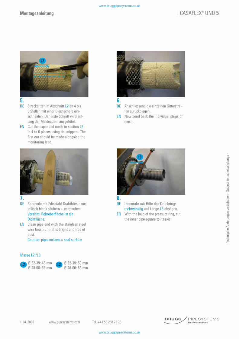
5.DE Streckgitter im Abschnitt L2 an 4 bis 6 Stellen mit einer Blechschere ein- schneiden. Der erste Schnitt wird ent- lang der Meldeadern ausgeführt.EN Cut the expanded mesh in section L2 in 4 to 6 places using tin snippers. The firstcutshouldbemadealongsidethe monitoring lead.
6.DE Anschliessend die einzelnen Gitterstrei- fen zurückbiegen.EN Now bend back the individual strips of mesh.
7.DE Rohrende mit Edelstahl-Drahtbürste me- tallisch blank säubern + entstauben. Vorsicht:Rohroberflächeistdie Dichtfläche.EN Clean pipe end with the stainless steel wire brush until it is bright and free of dust. Caution: pipe surface = seal surface
8.DE Innenrohr mit Hilfe des Druckrings rechtwinklig auf Länge L3 absägen.EN With the help of the pressure ring, cut the inner pipe square to its axis.
Ø 22-39: 48 mmØ 48-60: 55 mm
Masse L2 /L3:
Ø 22-39: 50 mmØ 48-60: 63 mm
L2
L3
L2 L3
www.bruggpipesystems.co.uk
www.bruggpipesystems.co.uk
1. 04. 2009 www.pipesystems.com Tel. +41 56 268 78 78
CASAFLEX® UNO 6
- Tec
hnis
che
Ände
rung
en v
orbe
halte
n - S
ubje
ct to
tech
nica
l cha
nge
-
Montageanleitung
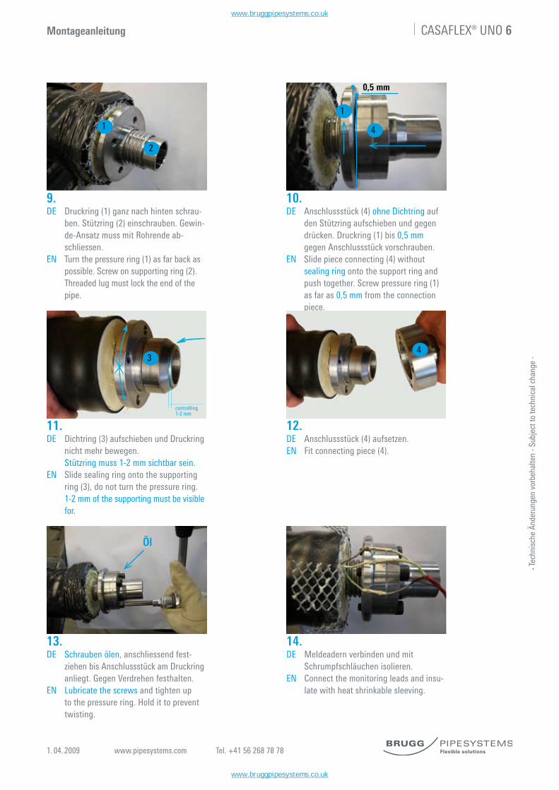
9.DE Druckring (1) ganz nach hinten schrau- ben. Stützring (2) einschrauben. Gewin- de-Ansatz muss mit Rohrende ab- schliessen.EN Turn the pressure ring (1) as far back as possible. Screw on supporting ring (2). Threaded lug must lock the end of the pipe.
10.DE Anschlussstück (4) ohne Dichtring auf den Stützring aufschieben und gegen drücken. Druckring (1) bis 0,5 mm gegen Anschlussstück vorschrauben.EN Slide piece connecting (4) without sealing ring onto the support ring and push together. Screw pressure ring (1) as far as 0,5 mm from the connection piece.
11.DE Dichtring (3) aufschieben und Druckring nicht mehr bewegen. Stützring muss 1-2 mm sichtbar sein.EN Slide sealing ring onto the supporting ring (3), do not turn the pressure ring. 1-2 mm of the supporting must be visible for.
0,5 mm
controlling1-2 mm
12.DE Anschlussstück (4) aufsetzen.EN Fit connecting piece (4).
14.DE Meldeadern verbinden und mit Schrumpfschläuchen isolieren.EN Connect the monitoring leads and insu- late with heat shrinkable sleeving.
13.DE Schrauben ölen, anschliessend fest- ziehen bis Anschlussstück am Druckring anliegt. Gegen Verdrehen festhalten. EN Lubricate the screws and tighten up to the pressure ring. Hold it to prevent twisting.
Öl
1
2
1
4
43
www.bruggpipesystems.co.uk
www.bruggpipesystems.co.uk

1. 04. 2009 www.pipesystems.com Tel. +41 56 268 78 78
CASAFLEX® UNO 7
- Tec
hnis
che
Ände
rung
en v
orbe
halte
n - S
ubje
ct to
tech
nica
l cha
nge
-
Montageanleitung
15.DE Das Streckgitter mit dem Hammer der Kontur des Druckringes anpassen und entsprechend einkürzen.EN Flatten the expanded mesh with the hammersothatitfitstheshapeofthe pressure ring, cutting it back where necessary.
17.DE Jeweils 2 der montierten Schrauben entfernen und mit Hilfe der Unter- lagsscheiben die Blechkappe gegen den Druckring pressen.EN Remove two of the mounted screws and press the metal cap against the pres- sure ring using the washers.
18.DE Dichtmanschette mit weicher Flamme mittig auf die Schutzkappe/Mantelrohr schrumpfen.EN Shrink the sealing sleeve onto the pro- tective cap / outer jacket using a soft flame.Ensuringitispositionedcen trally.
16.DE Die Meldeadern durch die Schutzkap- pe (5) durchziehen und montieren.EN Pull the monitoring leads through the protective cap (5) and install.
5
www.bruggpipesystems.co.uk
www.bruggpipesystems.co.uk


![HydrauLikHammer Serie XB - dizv3061bgivy.cloudfront.netdizv3061bgivy.cloudfront.net/mmc-assets/pdfs/data_sheets_XB-550is-2100... · Betriebsdruck Hammer [bar] 105 - 130 105 - 130](https://img.pdfslide.org/doc/110x75/5e0e5809e059ce52c30d3b66/hydraulikhammer-serie-xb-betriebsdruck-hammer-bar-105-130-105-130-115-.jpg)

![Optimierung 1...(b) ϕ heißt Zielfunktion [engl.: objective function], F heißt zul¨assiger Bereich [engl.: feasible region] der gegebenen Aufgabe. Jeder Punkt x∈ F heißt zul¨assig](https://img.pdfslide.org/doc/110x75/5febfab46df6691b384d66ad/optimierung-1-b-heit-zielfunktion-engl-objective-function-f-heit.jpg)