Embed Size (px)
Citation preview
Mikołaj Jaszczur, BSc
Comparison of planar and spherical tunnel faces
Master’s Thesis
Submitted in fulfilment of the requirements for the degree of
Diplom-Ingenieur
Master’s programme Civil Engineering, Geotechnics and Hydraulics
at
Graz University of Technology
O. Univ.-Prof. Dipl.-Ing. Dr. mont. Wulf Schubert
Institute of Rock Mechanics and Tunnelling
Graz University of Technology
Dipl.-Ing. Michael Rudolf Henzinger
Institute of Rock Mechanics and Tunnelling
Graz University of Technology
Graz, November 2017
EIDESSTATTLICHE ERKLÄRUNG
AFFIDAVIT
Ich erkläre an Eides statt, dass ich die vorliegende Arbeit selbstständig verfasst, andere als
die angegebenen Quellen/Hilfsmittel nicht benutzt, und die den benutzten Quellen wörtlich
und inhaltlich entnommenen Stellen als solche kenntlich gemacht habe. Das in
TUGRAZonline hochgeladene Textdokument ist mit der vorliegenden Masterarbeit
identisch.
I declare that I have authored this thesis independently, that I have not used other than the
declared sources/resources, and that I have explicitly marked all material which has been
quoted either literally or by content from the used sources. The text document uploaded to
TUGRAZonline is identical to the present master‘s thesis.
Datum / Date Unterschrift / Signature

Acknowledgements
My first thank goes to my supervisor Professor Dr. Wulf Schubert, head of the Institute of
Rock Mechanics and Tunnelling at the Graz University of Technology. I would like to thank
him for the opportunity to prepare this master’s thesis.
Special thanks to Dipl.-Ing. Michael Henzinger for his help and assistance during the
preparation of this work.
Finally, I would like to thank my father Robert for his support and encouragement during my
studies in Poland, Germany, Austria and Taiwan.
Abstract
Tunnels driven in poor ground conditions require additional measures to maintain the
stability of the heading. While the face instability in a poor ground always pose an issue,
changing the face from a planar to a spherical shape may contribute to a safer and faster
construction. Up to now there have been only few attempts to investigate the behaviour of
spherical tunnel faces. Thus, a firm statement concerning the performance of the spherical
face cannot be made. This thesis compares the behaviour of planar and spherical faces in
conventional tunnelling. For the purpose of this work a three-dimensional numerical model
using a FDM software was prepared. With the application of elastic perfect-plastic
constitutive models a realistic behaviour of the ground was achieved. The calculations
spanned the range of sequential and full face excavations with and without a tunnel support.
The effectiveness of the spherical face was described in terms of a dimensionless
parameter. This study showed that the spherical face experiences lower longitudinal
deformations than the planar one. The volume of the failure zone ahead of the heading is
significantly reduced. On top of that, the application of a tunnel support enhances the
effectiveness of the spherical face. As such, comparing with the planar face, longitudinal
face displacements can be reduced by a factor of five. Indeed, the findings of this work
suggest that in specific ground conditions the application of the spherical face may eliminate
the necessity of a face bolting. As a result, material demands can be reduced and
excavation speed notably increased.
Keywords: Spherical face, Planar face, Tunnel support, Comparison, FDM, Arching, Stress,
Displacement, Plastic radius, NATM
Kurzfassung
Tunnelvortrieb in schlechten Bodenverhätnissen erfordert zusätzliche Maßnahmen, um die
Stabilität der Ortsbrust sicherzustellen und die Verformungen in einem tolerierbaren Bereich
zu halten. Bis heute gab es nur wenige Untersuchungen zum Verhalten einer sphärischen
Ortsbrust. Somit kann keine eindeutige Aussage über das Verhalten einer sphärischen
Brust gemacht werden. Diese Masterarbeit beinhaltet die Gegenüberstellung der Verhalten
von vertikaler und sphärischer Ortsbrust im konventionellen Tunnelbau. Im Rahmen dieser
Arbeit wurde ein dreidimensionales numerisches Modell unter Verwendung einer FDM-
Software erarbeitet. Mit der Anwendung elastischer perfekt-plastischer Stoffgesetze wurde
ein realistisches Verhalten des Bodens erreicht. Die Berechnungen umfassten den Voll-
sowie Teilausbruch mit und ohne Tunnelstützung. Die Wirksamkeit einer sphärischen
Ortsbrust wurde mit Hilfe eines dimensionslosen Faktors beschrieben. Diese Studie zeigte,
dass die sphärische Ortsbrust geringere Deformationen erfährt als eine vertikale Ortsbrust.
Das Volumen der plastischen Zonen vor der Ortsbrust wird deutlich reduziert. Durch den
Einbau einer Tunnelschale können die Verschiebungen im Vergleich zu einer ebenen
Tunnelortsbrust um einen Faktor von fünf reduziert werden. Diese Arbeit zeigt auf, dass
durch die Anwendung einer sphärischen Ortsbrust die Notwendigkeit der
Ortsbrustankerung in bestimmten Bodenverhältnissen eliminiert werden kann. Als Folge
davon können die Materialanforderungen reduziert und die Vortriebsleistung deutlich erhöht
werden.
Schlüsswort: Sphärische Ortsbrust, Vertikale Ortsbrust, Tunnelstützung,
Gegenüberstellung, FDM, Gewölbewirkung, Spannung, Tunnelverformung, Plastische
Zone, NÖT
i
Table of contents
1 Introduction 1
1.1 State of the art................................................................................................. 1
1.2 Aim of the work ............................................................................................... 6
1.3 Outline …………………………………………………………………………………6
2 Methodology 8
2.1 Numerical model ............................................................................................. 8
2.2 Material characteristic ................................................................................... 10
2.3 Modelling sequence ...................................................................................... 13
2.4 Data analysis ................................................................................................ 18
2.5 Model validation ............................................................................................ 19
3 Results 23
3.1 Failure mechanism ........................................................................................ 23
3.2 Unsupported tunnel ....................................................................................... 25
3.3 Shotcrete lining ............................................................................................. 31
3.4 Shotcrete lining with face bolting ................................................................... 39
4 Discussion 42
5 Conclusion 48
5.1 Summary ....................................................................................................... 48
5.2 Outlook ......................................................................................................... 49
Bibliography 51
Appendix 54
ii
List of figures
Figure 1.1: a) Three-dimensional failure mechanism (Horn, 1961); b) Forces acting on the
prism and the sliding wedge (Horn, 1961) .......................................................................... 2
Figure 1.2: Two- and three-dimensional failure mechanisms proposed by Krause (1987):
a) Circular; b) Semi-circular; c) Spherical ........................................................................... 2
Figure 1.3: Collapse mechanisms proposed by Leca & Dormieux (1990): a) Two-block
mechanism; b) Single-block mechanism ............................................................................ 3
Figure 1.4: Tunnel face geometry according to Kolymbas (1998) ..................................... 4
Figure 2.1: The dimensions of the numerical model and the global coordinate system ..... 9
Figure 2.2: Model boundary conditions and the extent of influenced zone ...................... 10
Figure 2.3: Description of the parameter 𝑟𝑠 ..................................................................... 14
Figure 2.4: Unsupported full face excavation with a varying parameter 𝑟𝑠 ...................... 16
Figure 2.5: Unsupported sequential excavation: a) With supporting core and vertical face;
b) Without core but with varying parameter 𝑟𝑠 ................................................................. 16
Figure 2.6: Supported full face excavation: a) Planar face; b) Spherical face .................. 17
Figure 2.7: Supported sequential excavation: a) With supporting core; b) Without
supporting core ................................................................................................................ 17
Figure 2.8: Comparison of the secondary stress state yielded with 𝐹𝐿𝐴𝐶3𝐷 and according
to Feder & Arwanitakis (1976) .......................................................................................... 20
Figure 2.9: Comparison of the secondary stress state ahead of the face yielded with
𝐹𝐿𝐴𝐶3𝐷 and according to Kolymbas (1998) ..................................................................... 21
Figure 2.10: Comparison of internal forces in the lining yielded with 𝐹𝐿𝐴𝐶3𝐷 and according
to the analytical solutions of Einstein & Schwartz (1979) and Ahrens et al. (1982): a) Normal
forces; b) Bending moments ............................................................................................ 22
Figure 3.1: a) Failure mechanism with a planar face; b) Vertical stresses as a function of
depth for different positions ahead of the face ................................................................. 24
Figure 3.2: a) Failure mechanism with a spherical face; b) Vertical stresses as a function
of depth for different positions ahead of the face .............................................................. 24
Figure 3.3: Secondary stress state at the face as a function of face distance. Unsupported
full face excavation: a) Model 1; b) Model 2; c) Model 3; d) Model 4; e) Legend .............. 26
iii
Figure 3.4: State of deformation at the face. Unsupported full face excavation: a) Model 1;
b) Model 2; c) Model 3; d) Model 4 ................................................................................... 27
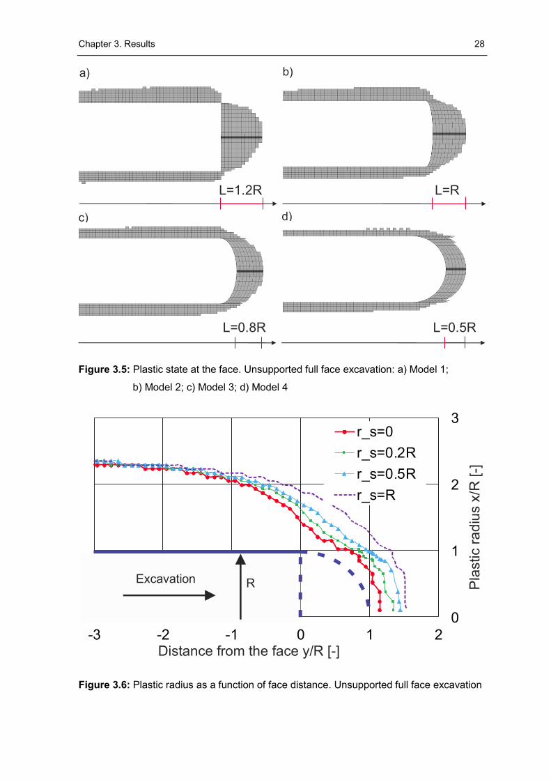
Figure 3.5: Plastic state at the face. Unsupported full face excavation: a) Model 1; b) Model
2; c) Model 3; d) Model 4 ................................................................................................. 28
Figure 3.6: Plastic radius as a function of face distance. Unsupported full face
excavation ....................................................................................................................... 28
Figure 3.7: Secondary stress state at the face as a function of face distance. Unsupported
sequential excavation: a) Model A; b) Model B; c) Model C; d) Model D .......................... 29
Figure 3.8: Comparison of face displacement. Unsupported sequential excavation:
a) Model A; b) Model B; c) Model C; d) Model D .............................................................. 30
Figure 3.9: Plastic state at the face. Unsupported sequential excavation: a) Model A;
b) Model B; c) Model C; d) Model D ................................................................................. 31
Figure 3.10: Secondary stress state at the face as a function of face distance. Supported
full face excavation: a) Model 1; b) Model 2; c) Model 3; d) Model 4 ................................ 32
Figure 3.11: Vertical stresses as a function of the depth shown for different positions ahead
of the face. Supported full face excavation: a) Vertical face; b) Spherical face ................. 33
Figure 3.12: Internal forces in the face support. Supported full face excavation: a) Model 1;
b) Model 2; c) Model 3; d) Model 4 ................................................................................... 34
Figure 3.13: Internal forces in the support at the tunnel wall. Supported full face excavation:
a) Model 1; b) Model 2; c) Model 3; d) Model 4 ................................................................ 35
Figure 3.14: State of deformation at the face. Supported full face excavation: a) Model 1;
b) Model 2; c) Model 3; d) Model 4 ................................................................................... 35
Figure 3.15: Plastic zone around the excavation. Supported full face excavation:
a) Model 1; b) Model 2; c) Model 3; d) Model 4 ................................................................ 36
Figure 3.16: Comparison of the plastic radius. Supported full face excavation ................ 37
Figure 3.17: Secondary stress states as a function of face distance. Supported sequential
excavation: a) Model A; b) Model B; c) Model C; d) Model D ........................................... 37
Figure 3.18: State of deformation at the face. Supported sequential excavation: a) Model
A; b) Model B; c) Model C; d) Model D ............................................................................. 38
Figure 3.19: Plastic state at the tunnel face. Supported sequential excavation: a) Model A;
b) Model B; c) Model C; d) Model D ................................................................................. 39
iv
Figure 3.20: State of deformation at the face. Full face excavations supported with
shotcrete and bolts: a) Model 1; b) Model 2; c) Model 3; d) Model 4 ................................ 40
Figure 3.21: Plastic state at the face with shotcrete and face bolts. Full face excavations:
a) Model 1; b) Model 2; c) Model 3; d) Model 4 ................................................................ 41
Figure 3.22: Comparison of plastic radius at the face supported with shotcrete and bolts.
Full face excavations ....................................................................................................... 41
Figure 4.1: The reduction factor 𝑑𝑟𝑒𝑑 as a function of the 𝑟𝑠. Full face excavations ....... 44
Figure 4.2: The reduction factor 𝑑𝑟𝑒𝑑 depending on the type of the sequential
excavation ....................................................................................................................... 44
Figure 4.3: a) Full face excavation supported with shotcrete (model A); b) Full face
excavation supported with shotcrete and face bolts (model B); c) Spherical full face
excavation supported with shotcrete (model C); d) Top heading excavation supported with
shotcrete and supporting core (model D) ......................................................................... 45
Figure 4.4: Deformation at the face with the Mohr-Coulomb. Model A ............................ 46
Figure 4.5: Deformation at the face with the Mohr-Coulomb: a) Model B; b) Model C ..... 46
Figure 4.6: Deformation at the face with the Mohr-Coulomb. Model D ............................ 47
Figure 4.7: Deformation at the face with the Plastic Hardening. Model A ........................ 47
Figure 4.8: Deformation at the face with the Plastic Hardening: a) Model B; b) Model C . 47
v
List of tables
Table 2.1: The dimensions of the numerical model ........................................................... 9
Table 2.2: Sets of ground parameters valid with Mohr-Coulomb model ........................... 10
Table 2.3: Set of ground parameters valid with Plastic Hardening model ........................ 11
Table 2.4: Input parameters of the shotcrete lining .......................................................... 12
Table 2.5: Input parameters of the face bolts .................................................................. 12
Table 2.6: The dimensions of the excavation parts valid for a sequential excavation
(e.g. models A, B, C and D) ............................................................................................. 17
Table 2.7: Control points ................................................................................................. 18
Table 2.8: Stress state at the level of tunnel crown and invert ......................................... 20
vi
Abbreviations
FDM ...............Finite Difference Method
FE ..................Finite Element
MC .................Mohr-Coulomb
NATM ............New Austrian Tunnelling Method
PH .................Plastic-Hardening
SpC ...............Sprayed Concrete
2D ..................two-dimensional
3D ..................three-dimensional
vii
Symbols
Capital letters
A ....................cross sectional area of grouted bolts [m²]
D ....................tunnel diameter [m]
E ....................elastic modulus of the ground [MPa]
E50,ref ..............secant modulus for primary triaxial loading [MPa]
Ean .................elastic modulus bolts [MPa]
Eoed,ref .............tangent modulus for oedometric loading [MPa]
Espc ................Young’s modulus shotcrete [MPa]
Eur,ref ...............secant modulus for un- and reloading [MPa]
G1 ..................Dead weight of vertical prism [-]
G2 ..................Dead weight of inclined wedge [-]
H1 ..................Model height (overburden) [m]
H2 ..................Model depth [m]
K0 ...................coefficient of earth pressure at rest [-]
L ....................model length [m]
La ...................length of bolts [m]
M ...................bending moment in tunnel lining [kNm]
N ....................normal force in tunnel lining [kN]
P ....................vertical load on the sliding wedge [-]
R ....................tunnel radius [m]
R1 ..................Stabilizing force due to friction along the vertical prism [-]
R2 ..................Stabilizing force acting on the sliding surface [-]
Rf ...................failure ratio [-]
S ....................face support [-]
T2 ...................frictional resistance force along the sliding surface [-]
W ...................model width [m]
viii
Lower case letters
c ....................ground cohesion [kPa]
cg ...................grout cohesive strength [kPa]
dred .................ratio of longitudinal displacement of spherical and vertical faces [-]
kg ...................grout stiffness [MPa]
kp ...................earth pressure coefficient [-]
m ...................exponent of the Ohde/Janbu law [-]
pg ...................grout perimeter [m]
pi ....................support pressure [kPa]
pref ..................reference pressure [MPa]
ro ....................distance from the face [m]
rp ....................plastic radius [m]
rs ....................sphere radius [m]
tf .....................thickness of shotcrete at the face [m]
tw ....................thickness of shotcrete in the wall [m]
x ....................dimension along the x-axis [m]
y ....................dimension along the y-axis [m]
z ....................dimension along the z-axis [m]
Greek letters
γ ....................unit weight [kN/m³]
ν ....................Poisson’s ratio of ground mass [-]
νsh ..................Poisson’s ratio of shotcrete [-]
νur ..................Poisson’s ratio unloading-reloading [-]
σ0 ...................initial stress [MPa]
σr ...................radial stress [MPa]
σrad,el ..............elastic part of radial stress [MPa]
σrad,pl ..............plastic part of radial stress MPa]
σt ...................tangential stress [MPa]
σtan,el ...............elastic part of tangential stress [MPa]
σtan,pl ...............plastic part of tangential stress [MPa]
σy ...................horizontal stress [MPa]
σz ...................vertical stress [MPa]
φ ...................friction angle [°]
ψ ...................dilatancy angle [°]
ω ...................inclination of the sliding wedge [°]
1
1 Introduction
1.1 State of the art
1.1.1 Theoretical methods concerning tunnel face stability
The tunnel face is considered to play an essential role in the stability of the whole
tunnel. To date several attempts have been made to describe the behaviour of the
advancing tunnel face. Theoretical models, numerical investigations and small-scale
laboratory tests have been carried out as part of this research.
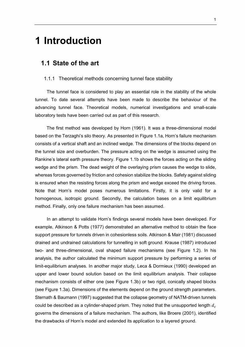
The first method was developed by Horn (1961). It was a three-dimensional model
based on the Terzaghi’s silo theory. As presented in Figure 1.1a, Horn’s failure mechanism
consists of a vertical shaft and an inclined wedge. The dimensions of the blocks depend on
the tunnel size and overburden. The pressure acting on the wedge is assumed using the
Rankine’s lateral earth pressure theory. Figure 1.1b shows the forces acting on the sliding
wedge and the prism. The dead weight of the overlaying prism causes the wedge to slide,
whereas forces governed by friction and cohesion stabilize the blocks. Safety against sliding
is ensured when the resisting forces along the prism and wedge exceed the driving forces.
Note that Horn’s model poses numerous limitations. Firstly, it is only valid for a
homogenous, isotropic ground. Secondly, the calculation bases on a limit equilibrium
method. Finally, only one failure mechanism has been assumed.
In an attempt to validate Horn’s findings several models have been developed. For
example, Atkinson & Potts (1977) demonstrated an alternative method to obtain the face
support pressure for tunnels driven in cohesionless soils. Atkinson & Mair (1981) discussed
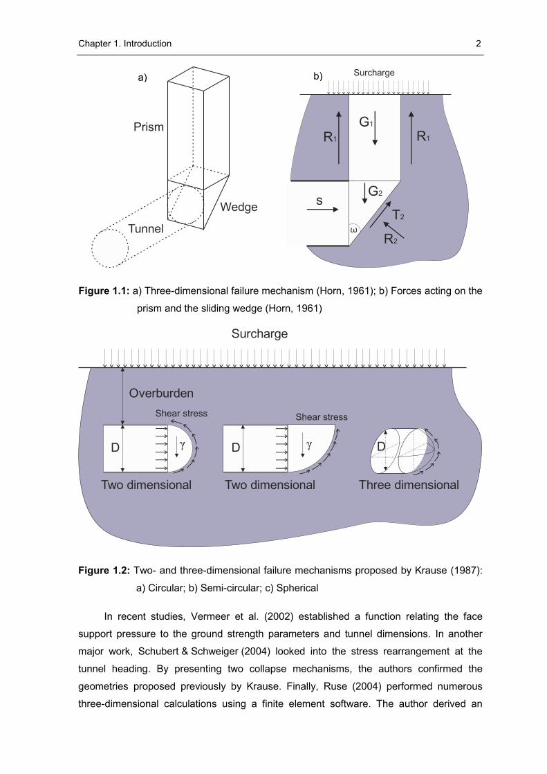
drained and undrained calculations for tunnelling in soft ground. Krause (1987) introduced
two- and three-dimensional, oval shaped failure mechanisms (see Figure 1.2). In his
analysis, the author calculated the minimum support pressure by performing a series of
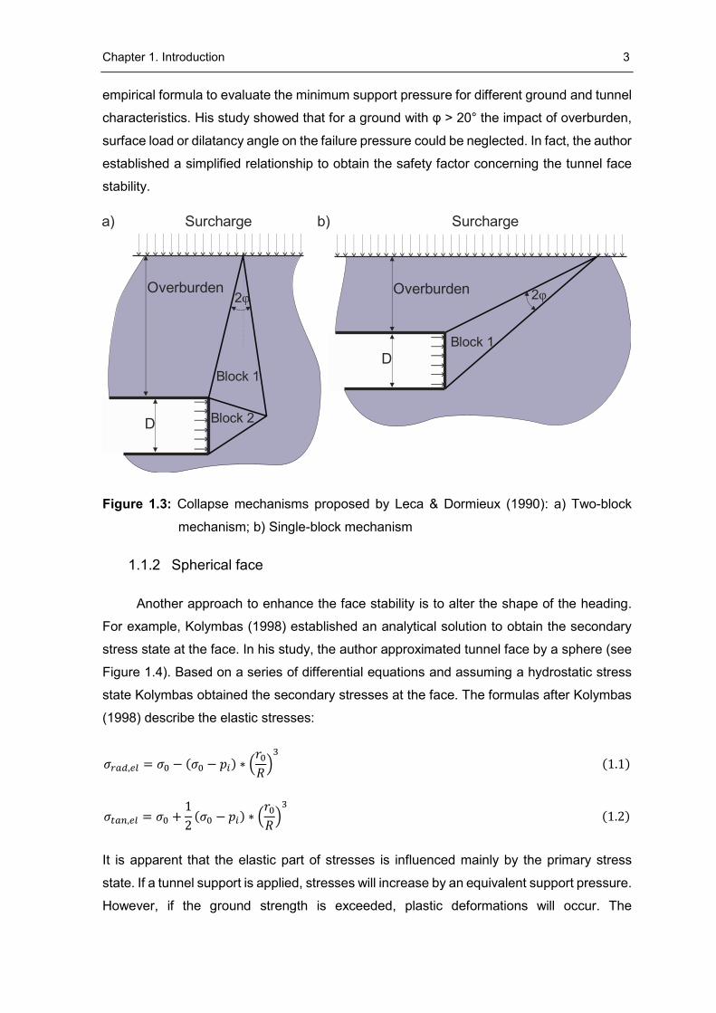
limit-equilibrium analyses. In another major study, Leca & Dormieux (1990) developed an
upper and lower bound solution based on the limit equilibrium analysis. Their collapse
mechanism consists of either one (see Figure 1.3b) or two rigid, conically shaped blocks
(see Figure 1.3a). Dimensions of the elements depend on the ground strength parameters.
Sternath & Baumann (1997) suggested that the collapse geometry of NATM-driven tunnels
could be described as a cylinder-shaped prism. They noted that the unsupported length 𝑑𝑐
governs the dimensions of a failure mechanism. The authors, like Broere (2001), identified
the drawbacks of Horn’s model and extended its application to a layered ground.
Chapter 1. Introduction 2
Figure 1.1: a) Three-dimensional failure mechanism (Horn, 1961); b) Forces acting on the
prism and the sliding wedge (Horn, 1961)
Figure 1.2: Two- and three-dimensional failure mechanisms proposed by Krause (1987):
a) Circular; b) Semi-circular; c) Spherical
In recent studies, Vermeer et al. (2002) established a function relating the face
support pressure to the ground strength parameters and tunnel dimensions. In another
major work, Schubert & Schweiger (2004) looked into the stress rearrangement at the
tunnel heading. By presenting two collapse mechanisms, the authors confirmed the
geometries proposed previously by Krause. Finally, Ruse (2004) performed numerous
three-dimensional calculations using a finite element software. The author derived an
Prism
Wedge
Tunnel
R1 R1
G1
T2
R2
sG2
ω
Surcharge
Overburden
D
Surcharge
γ
Shear stress
γD
Two dimensional Two dimensional Three dimensional
D
Shear stress
a) b)
Chapter 1. Introduction 3
empirical formula to evaluate the minimum support pressure for different ground and tunnel
characteristics. His study showed that for a ground with φ > 20° the impact of overburden,
surface load or dilatancy angle on the failure pressure could be neglected. In fact, the author
established a simplified relationship to obtain the safety factor concerning the tunnel face
stability.
Figure 1.3: Collapse mechanisms proposed by Leca & Dormieux (1990): a) Two-block
mechanism; b) Single-block mechanism
1.1.2 Spherical face
Another approach to enhance the face stability is to alter the shape of the heading.
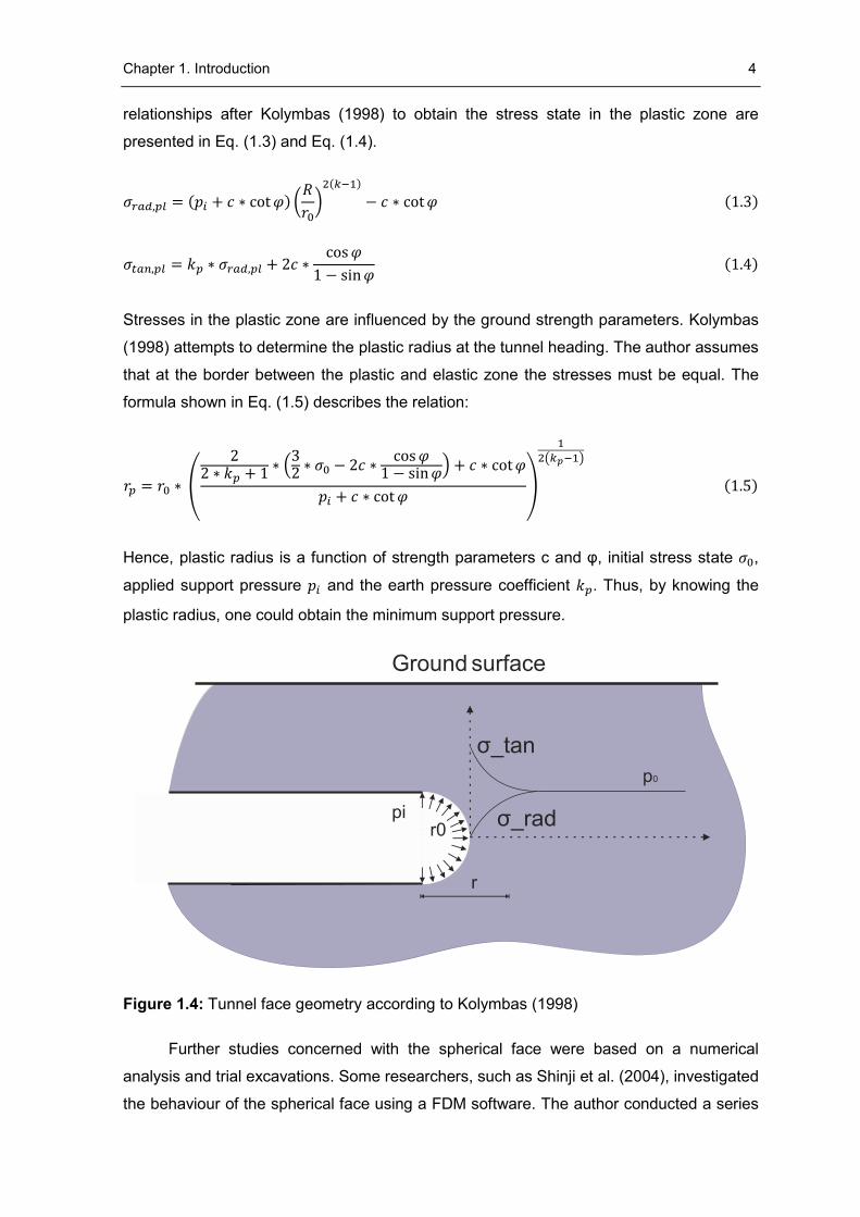
For example, Kolymbas (1998) established an analytical solution to obtain the secondary
stress state at the face. In his study, the author approximated tunnel face by a sphere (see
Figure 1.4). Based on a series of differential equations and assuming a hydrostatic stress
state Kolymbas obtained the secondary stresses at the face. The formulas after Kolymbas
(1998) describe the elastic stresses:
𝜎𝑟𝑎𝑑,𝑒𝑙 = 𝜎0 − (𝜎0 − 𝑝𝑖) ∗ (𝑟0
𝑅)
3
(1.1)
𝜎𝑡𝑎𝑛,𝑒𝑙 = 𝜎0 +1
2(𝜎0 − 𝑝𝑖) ∗ (
𝑟0
𝑅)
3
(1.2)
It is apparent that the elastic part of stresses is influenced mainly by the primary stress
state. If a tunnel support is applied, stresses will increase by an equivalent support pressure.
However, if the ground strength is exceeded, plastic deformations will occur. The
Overburden
D
Block 1
Block 2
Surcharge
2φOverburden
DBlock 1
Surcharge
2φ
a) b)
Chapter 1. Introduction 4
relationships after Kolymbas (1998) to obtain the stress state in the plastic zone are
presented in Eq. (1.3) and Eq. (1.4).
𝜎𝑟𝑎𝑑,𝑝𝑙 = (𝑝𝑖 + 𝑐 ∗ cot 𝜑) (𝑅
𝑟0)
2(𝑘−1)
− 𝑐 ∗ cot 𝜑 (1.3)
𝜎𝑡𝑎𝑛,𝑝𝑙 = 𝑘𝑝 ∗ 𝜎𝑟𝑎𝑑,𝑝𝑙 + 2𝑐 ∗cos 𝜑
1 − sin 𝜑 (1.4)
Stresses in the plastic zone are influenced by the ground strength parameters. Kolymbas
(1998) attempts to determine the plastic radius at the tunnel heading. The author assumes
that at the border between the plastic and elastic zone the stresses must be equal. The
formula shown in Eq. (1.5) describes the relation:
𝑟𝑝 = 𝑟0 ∗ (
22 ∗ 𝑘𝑝 + 1
∗ (32 ∗ 𝜎0 − 2𝑐 ∗
cos 𝜑1 − sin 𝜑) + 𝑐 ∗ cot 𝜑
𝑝𝑖 + 𝑐 ∗ cot 𝜑)
1
2(𝑘𝑝−1)
(1.5)
Hence, plastic radius is a function of strength parameters c and φ, initial stress state 𝜎0,
applied support pressure 𝑝𝑖 and the earth pressure coefficient 𝑘𝑝. Thus, by knowing the
plastic radius, one could obtain the minimum support pressure.
Figure 1.4: Tunnel face geometry according to Kolymbas (1998)
Further studies concerned with the spherical face were based on a numerical
analysis and trial excavations. Some researchers, such as Shinji et al. (2004), investigated
the behaviour of the spherical face using a FDM software. The author conducted a series
r0σ_rad
σ_tan
pi
r
p0
Ground surface
Chapter 1. Introduction 5
of three-dimensional simulations and compared the behaviour of planar and spherical faces
in a poor, squeezing ground. The findings showed that the spherical face experiences lower
horizontal deformations than the vertical one. Based on those results the author anticipated
a formation of a load-bearing arch near the excavation contour. While this work included
plots of deformation, the author did not present the state of secondary stresses.
Furthermore, this study failed to consider the extent of the plastic zone around the
excavation.
In his analysis of spherical face, Kusumoto et al. (2013) performed a three-
dimensional FDM analysis with various excavation patterns. The simulations covered
different round lengths as well as numerous types and shapes of excavations. In general,
spherical face experienced lower deformations at the crown as well as at the face. The
author highlighted different distribution of displacements with both faces. Furthermore, the
simulations of the spherical face revealed a notable reduction of stresses in the tunnel
support. The author compared those findings with the observations from a trial excavation
in the Hachinoshiri Tunnel. Indeed, lower deformations at the crown and in the sidewalls
with the spherical face have been reported. Again, the presence of a load-bearing arch near
the heading was assumed. While this study was conducted with relatively good ground
conditions, no attempt was made to repeat the simulations with a soft ground. Besides, the
author did not analyse the behaviour of a tunnel lining at the face.
Finally, Amemiya et al. (2014) published numerous experiences with a spherical face
collected during the construction of the Shin-Takarahama Tunnel in Japan. The assessment
of the face stability was made by calculating the frequency and consequences of rock falls.
In addition, Amemiya et al. (2014) compared tunnel deformations and forces induced in the
lining. However, the displacements were too low to observe a notable trend. Furthermore,
only marginal differences in the shotcrete stresses have been reported. Like the previous
researchers, the author suggested an advanced development of a load-bearing arch close
to the heading. Though, notable advantages of the spherical face have been mentioned.
For example, although the stability of a spherical face is comparable to the vertical face with
an auxiliary bench, all the advantages of a full face excavation are maintained. This study,
however, poses some limitations. While the work focused on the onsite experiences, a
verification of the results obtained onsite by a numerical simulation is missing. Furthermore,
the correctness of the stability assessment may be disputable.
Chapter 1. Introduction 6
1.2 Aim of the work
The effect of a spherical face on the tunnel behaviour has not been fully investigated.
Firstly, most of the previous studies have been restricted to only one geometry set. Only
Kusumoto et al. (2013) performed an analysis to relate the geometry of a spherical face to
the magnitude of displacements. Secondly, only Shinji et al. (2004) carried out numerical
calculations assuming poor ground conditions. Thirdly, to date studies have not thoroughly
dealt with a description of the face displacements. Although many researchers assumed
the presence of a load-bearing arch ahead of the heading, none of them conducted a
comprehensive stress analysis. Finally, there has been hardly any work concerned with the
extent of the plastic zone ahead of the face. Hence, until now, a firm statement on the
effectiveness of this method was not feasible. Therefore, the aim of this work was to provide
a numerical basis for an execution of the spherical face onsite. To attain this goal, a number
of objectives should be fulfilled:
To investigate the relationship between the shape of the face and
displacement development
To compare the volume of the plastic zone ahead of the heading
To analyse the collapse mechanisms taking place with planar and spherical
faces
To compare the location of a load-bearing arch ahead of the heading
1.3 Outline
This thesis is divided into five parts. Chapter 1 illustrates the background and the
objectives of this work.
Chapter 2 deals with the methodology. At first, the FDM software used for the purpose
of this study is introduced. Then, the model geometry together with the material parameters
and constitutive equations are described. Subsection 2.4 introduces the scope of the
analysis. This is followed by a description of the modelling sequence. Finally, subsection
2.5 deals with the validation of the model. Within this part, the results of the initial tests have
been compared with analytical solutions. Thus, plausibility of the numerical results was
verified. Finally, an attempt was made to check the impact of the constitutive model on the
results.
Chapter 1. Introduction 7
Chapter 3 deals with the findings of the simulations. This part has been divided into
four sections. At first, the author looked into the failure mechanisms occurring with planar
and spherical faces. Thus, the reader has a chance to observe the formation of the load-
bearing arch ahead of the heading. Next, chapter 3 presents the results concerning an
unsupported tunnel. Stresses, deformations and plastic zones calculated with different face
geometries have been compared. The results of simulations with a lined tunnel are the topic
of subsection 3.3. Thus, the reader gains a deeper insight into the distribution of internal
forces in the support. Finally, subsection 3.4 reveals the findings concerned with a tunnel
supported with shotcrete and face bolts.
Chapter 4 discusses the results from the previous section. The author examines the
data to qualitatively describe the effects of the spherical face. Finally, an attempt has been
made to draw some practice-related conclusions. Additional simulations have been
performed to check the validity of the stated hypothesis.
In chapter 5 the conclusion of this work is presented. A brief summary concerns the
first part of this chapter. This included findings, which emerged during the course of this
work. Finally, in subsection 5.2 an outlook into future research projects is shown.
8
2 Methodology
2.1 Numerical model
The stress state at the tunnel face is a three-dimensional problem. This means that
as a tunnel heading advances, a pre-relaxation occurs ahead of the face. Thus, only a three-
dimensional analysis can accurately simulate the ground behaviour at the face. Given the
above, the FDM programme “Fast Lagrangian Analysis of Continua in Three Dimensions”
(𝐹𝐿𝐴𝐶3𝐷) from ITASCA was used. 𝐹𝐿𝐴𝐶3𝐷provides a series of non-linear constitutive
models as well as built-in functions to simulate a tunnel support. Unlike other geotechnical
programs, 𝐹𝐿𝐴𝐶3𝐷 features a command-based user interface and a built-in coding language
called FISH.
Due to the axial symmetry only the right half of the cross section was modelled. The
mesh was composed of the 𝐹𝐿𝐴𝐶3𝐷 built-in elements. For the purpose of simplicity, a
circular tunnel cross section was chosen.
To date countless studies have been published to set a universal geometry of a 3D
numerical model. It is worth to mention the work by
Deutsche Gesellschaft für Geotechnik (2012). Wittke (1999), Meißner (1991) and
Meißner (1996) published typical model geometries. Yet, those publications present quite
conservative values. On one hand, Wittke (1999) suggests a model width of minimum 7R.
On the other hand, Ruse (2004) calculated the minimum face pressure with a model of only
4R width. The same model dimensions have been used by Kirsch (2015). In fact, Ruse
(2004) showed that model widths greater than 2R do not influence the results significantly.
With this in mind, the author performed a series of tests to investigate the impact of the
model size of the numerical results. Since the behaviour of the face was the primary interest
of this work, the model length has been found to be the most important factor. According to
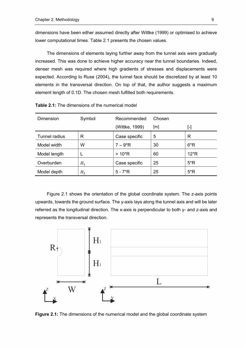
Ruse (2004), the displacements in the zones laying within 2D from the model boundaries
are influenced by the artificial boundary conditions. Golser (1999) pointed out that the
elements within 2.5D from the model boundary show an error associated with the model
edges (see Figure 2.2). Both authors term this part of the model as an “influence length”.
As such, Wittke (1984) suggests an influence length of 2D. Considering the above
statements, the length of the model was set to 6D. Furthermore, as pointed out by the cross
section A-A (see Figure 2.2), the results were analysed in a distance of 3D from both model
edges. Thus, the error caused by the artificial boundaries could be excluded. The remaining
Chapter 2. Methodology 9
dimensions have been either assumed directly after Wittke (1999) or optimised to achieve
lower computational times. Table 2.1 presents the chosen values.
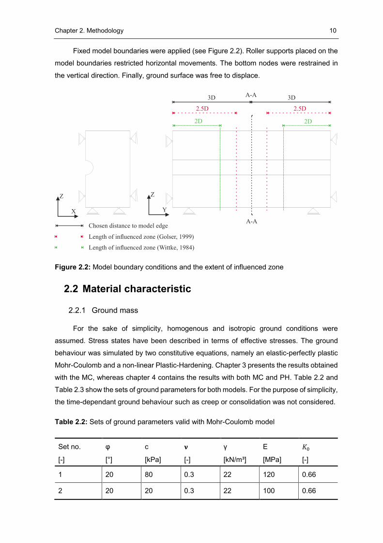
The dimensions of elements laying further away from the tunnel axis were gradually
increased. This was done to achieve higher accuracy near the tunnel boundaries. Indeed,
denser mesh was required where high gradients of stresses and displacements were
expected. According to Ruse (2004), the tunnel face should be discretized by at least 10
elements in the transversal direction. On top of that, the author suggests a maximum
element length of 0.1D. The chosen mesh fulfilled both requirements.
Table 2.1: The dimensions of the numerical model
Dimension Symbol Recommended Chosen
Unit (Wittke, 1999) [m] [-]
Tunnel radius R Case specific 5 R
Model width W 7 – 9*R 30 6*R
Model length L > 10*R 60 12*R
Overburden 𝐻1 Case specific 25 5*R
Model depth 𝐻2 5 - 7*R 25 5*R
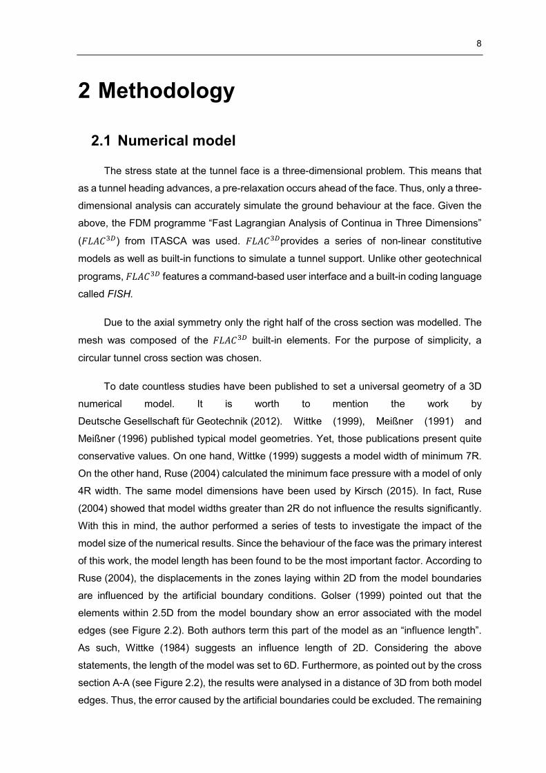
Figure 2.1 shows the orientation of the global coordinate system. The z-axis points
upwards, towards the ground surface. The y-axis lays along the tunnel axis and will be later
referred as the longitudinal direction. The x-axis is perpendicular to both y- and z-axis and
represents the transversal direction.
Figure 2.1: The dimensions of the numerical model and the global coordinate system
Z
X
Z
Y
L
H1
H1
W
R
Chapter 2. Methodology 10
Fixed model boundaries were applied (see Figure 2.2). Roller supports placed on the
model boundaries restricted horizontal movements. The bottom nodes were restrained in
the vertical direction. Finally, ground surface was free to displace.
Figure 2.2: Model boundary conditions and the extent of influenced zone
2.2 Material characteristic
2.2.1 Ground mass
For the sake of simplicity, homogenous and isotropic ground conditions were
assumed. Stress states have been described in terms of effective stresses. The ground
behaviour was simulated by two constitutive equations, namely an elastic-perfectly plastic
Mohr-Coulomb and a non-linear Plastic-Hardening. Chapter 3 presents the results obtained
with the MC, whereas chapter 4 contains the results with both MC and PH. Table 2.2 and
Table 2.3 show the sets of ground parameters for both models. For the purpose of simplicity,
the time-dependant ground behaviour such as creep or consolidation was not considered.
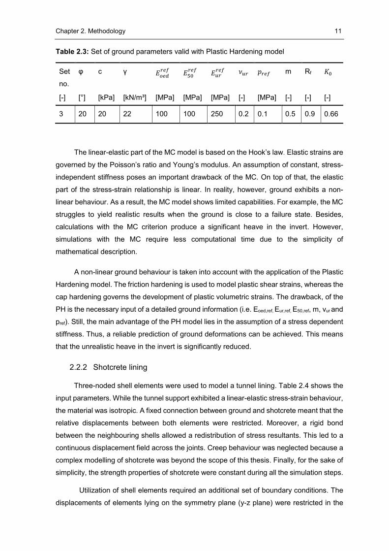
Table 2.2: Sets of ground parameters valid with Mohr-Coulomb model
Set no. φ c 𝛎 γ E 𝐾0
[-] [°] [kPa] [-] [kN/m³] [MPa] [-]
1 20 80 0.3 22 120 0.66
2 20 20 0.3 22 100 0.66
Z
X
Z
Y
2.5D 2.5D
3D 3DA-A
A-A
2D 2D
Chosen distance to model edge
Length of influenced zone (Golser, 1999)
Length of influenced zone (Wittke, 1984)
Chapter 2. Methodology 11
Table 2.3: Set of ground parameters valid with Plastic Hardening model
Set
no.
φ c γ 𝐸𝑜𝑒𝑑𝑟𝑒𝑓
𝐸50𝑟𝑒𝑓
𝐸𝑢𝑟𝑟𝑒𝑓
𝜈𝑢𝑟 𝑝𝑟𝑒𝑓 m Rf 𝐾0
[-] [°] [kPa] [kN/m³] [MPa] [MPa] [MPa] [-] [MPa] [-] [-] [-]
3 20 20 22 100 100 250 0.2 0.1 0.5 0.9 0.66
The linear-elastic part of the MC model is based on the Hook’s law. Elastic strains are
governed by the Poisson’s ratio and Young’s modulus. An assumption of constant, stress-
independent stiffness poses an important drawback of the MC. On top of that, the elastic
part of the stress-strain relationship is linear. In reality, however, ground exhibits a non-
linear behaviour. As a result, the MC model shows limited capabilities. For example, the MC
struggles to yield realistic results when the ground is close to a failure state. Besides,
calculations with the MC criterion produce a significant heave in the invert. However,
simulations with the MC require less computational time due to the simplicity of
mathematical description.
A non-linear ground behaviour is taken into account with the application of the Plastic
Hardening model. The friction hardening is used to model plastic shear strains, whereas the
cap hardening governs the development of plastic volumetric strains. The drawback, of the
PH is the necessary input of a detailed ground information (i.e. Eoed,ref, Eur,ref, E50,ref, m, νur and
pref). Still, the main advantage of the PH model lies in the assumption of a stress dependent
stiffness. Thus, a reliable prediction of ground deformations can be achieved. This means
that the unrealistic heave in the invert is significantly reduced.
2.2.2 Shotcrete lining
Three-noded shell elements were used to model a tunnel lining. Table 2.4 shows the
input parameters. While the tunnel support exhibited a linear-elastic stress-strain behaviour,
the material was isotropic. A fixed connection between ground and shotcrete meant that the
relative displacements between both elements were restricted. Moreover, a rigid bond
between the neighbouring shells allowed a redistribution of stress resultants. This led to a
continuous displacement field across the joints. Creep behaviour was neglected because a
complex modelling of shotcrete was beyond the scope of this thesis. Finally, for the sake of
simplicity, the strength properties of shotcrete were constant during all the simulation steps.
Utilization of shell elements required an additional set of boundary conditions. The
displacements of elements lying on the symmetry plane (y-z plane) were restricted in the
Chapter 2. Methodology 12
normal direction. In addition, the rotation about the axes lying on the global y-z plane was
not allowed.
Table 2.4: Input parameters of the shotcrete lining
Property Symbol Value Unit
Young’s modulus 𝐸𝑆𝑝𝑐 10500 [MPa]
Poisson’s ratio 𝜈 0.25 [-]
Thickness wall 𝑡𝑤 0.3 [m]
Thickness face 𝑡𝑓 0.1 [m]
Unit weight Γ 24 [kN/m³]
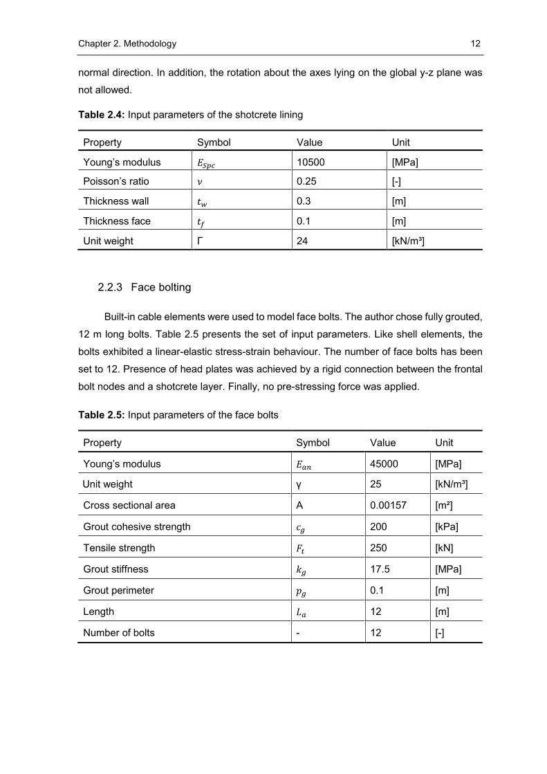
2.2.3 Face bolting
Built-in cable elements were used to model face bolts. The author chose fully grouted,
12 m long bolts. Table 2.5 presents the set of input parameters. Like shell elements, the
bolts exhibited a linear-elastic stress-strain behaviour. The number of face bolts has been
set to 12. Presence of head plates was achieved by a rigid connection between the frontal
bolt nodes and a shotcrete layer. Finally, no pre-stressing force was applied.
Table 2.5: Input parameters of the face bolts
Property Symbol Value Unit
Young’s modulus 𝐸𝑎𝑛 45000 [MPa]
Unit weight γ 25 [kN/m³]
Cross sectional area A 0.00157 [m²]
Grout cohesive strength 𝑐𝑔 200 [kPa]
Tensile strength 𝐹𝑡 250 [kN]
Grout stiffness 𝑘𝑔 17.5 [MPa]
Grout perimeter 𝑝𝑔 0.1 [m]
Length 𝐿𝑎 12 [m]
Number of bolts - 12 [-]
Chapter 2. Methodology 13
2.3 Modelling sequence
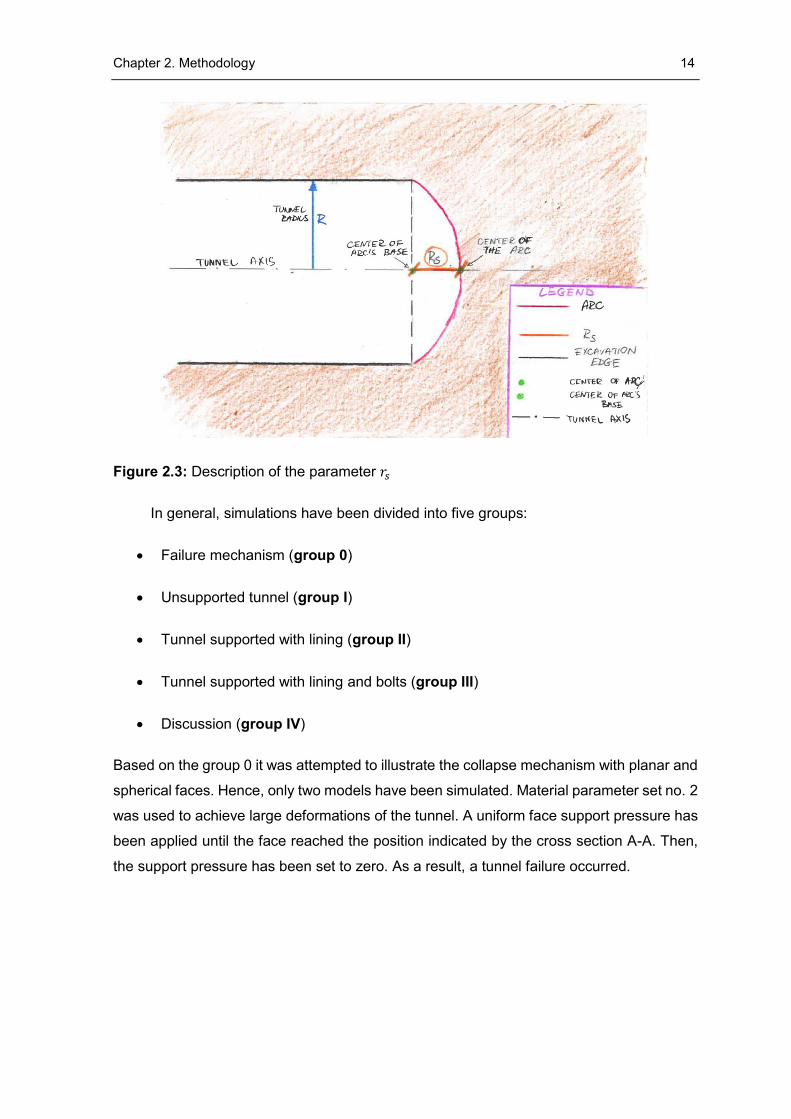
As already mentioned, the objective of this thesis was to compare different shapes of
the tunnel face. Thus, an additional parameter 𝑟𝑠 was developed to characterize the shape
of the face. Figure 2.3 shows the schema of a tunnel excavation with a spherical face. The
arch (solid pink line) represents the face contour. The parameter 𝑟𝑠 describes the length
from the arch center to the center of its base. In the later part of this work 𝑟𝑠 is related to the
tunnel radius R.
Numerical simulations were conducted according to the principles of the step-by-step
method (Wittke, 1999). The idea was to perform multiple rounds of excavation until the face
was in a sufficient distance from the model edges. Thus, the influence of the artificial
boundaries could be reduced.
The round length was set to 1 m. State of equilibrium was described in terms of a
mechanical ratio. This value describes the relation between the out-of-balance force and
the average mechanical force. The ratio was varied between 10−5 and 10−6. However, it
turned out that it had a low impact on the results. For example, with a ratio of 10−6 the face
longitudinal displacement increased by only 5%. Moreover, the course of stresses obtained
with both ratios was almost identical. Related diagrams can be found in Appendix A.
However, the lower ratio caused an increase of the computational time by a factor of three.
As a result, the simulation required 22h. Therefore, the ratio of 10−5 was maintained for
further calculations. Given the above, it proved to be a satisfying compromise between the
accuracy of calculations and the computational time.
Chapter 2. Methodology 14
Figure 2.3: Description of the parameter 𝑟𝑠
In general, simulations have been divided into five groups:
Failure mechanism (group 0)
Unsupported tunnel (group I)
Tunnel supported with lining (group II)
Tunnel supported with lining and bolts (group III)
Discussion (group IV)
Based on the group 0 it was attempted to illustrate the collapse mechanism with planar and
spherical faces. Hence, only two models have been simulated. Material parameter set no. 2
was used to achieve large deformations of the tunnel. A uniform face support pressure has
been applied until the face reached the position indicated by the cross section A-A. Then,
the support pressure has been set to zero. As a result, a tunnel failure occurred.
Chapter 2. Methodology 15
The calculations carried out as a part of groups I, II have been divided into two
subsections, namely a full face and a sequential excavation. Within the group III only full
face excavations have been simulated. Four different face shapes are considered for the
analysis of a full face excavation:
𝑟𝑠 = 0 (model 1)
𝑟𝑠 = 0.2 ∗ 𝑅 (model 2)
𝑟𝑠 = 0.5 ∗ 𝑅 (model 3)
𝑟𝑠 = 𝑅 (model 4)
The models are illustrated in Figure 2.4 and Figure 2.6.
Calculations with a sequential excavation have been classified into four groups:
Top heading with vertical face - 𝑟𝑠 = 0 (model A)
Top heading with a core and vertical face - 𝑟𝑠 = 0 (model B)
Top heading with spherical face - 𝑟𝑠 = 0.2 ∗ 𝑅 (model C)
Top heading with a core and spherical face - 𝑟𝑠 = 0.5 ∗ 𝑅 (model D)
Figure 2.5 and Figure 2.7 show the detailed geometries of those models. The reader is
asked to remember the naming convention presented above. In order to avoid confusion,
in the later part of this work only underlined, bold typed terms (e.g. model 1, model B) will
be used.
The cross section of the sequential excavation was divided into a top heading and an
invert. Additionally, two models contained a supporting core. As such, the dimensions
concerning tunnel face, invert and the core have been summarized in Table 2.6. Values
given in the brackets refer to the tunnel radius R.
Chapter 2. Methodology 16
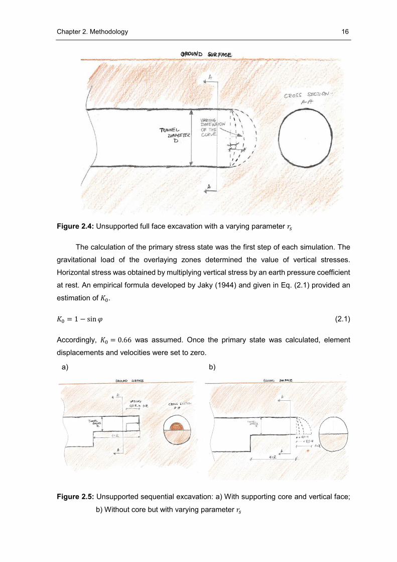
Figure 2.4: Unsupported full face excavation with a varying parameter 𝑟𝑠
The calculation of the primary stress state was the first step of each simulation. The
gravitational load of the overlaying zones determined the value of vertical stresses.
Horizontal stress was obtained by multiplying vertical stress by an earth pressure coefficient
at rest. An empirical formula developed by Jaky (1944) and given in Eq. (2.1) provided an
estimation of 𝐾0.
𝐾0 = 1 − sin 𝜑 (2.1)
Accordingly, 𝐾0 = 0.66 was assumed. Once the primary state was calculated, element
displacements and velocities were set to zero.
Figure 2.5: Unsupported sequential excavation: a) With supporting core and vertical face;
b) Without core but with varying parameter 𝑟𝑠
a) b)
Chapter 2. Methodology 17
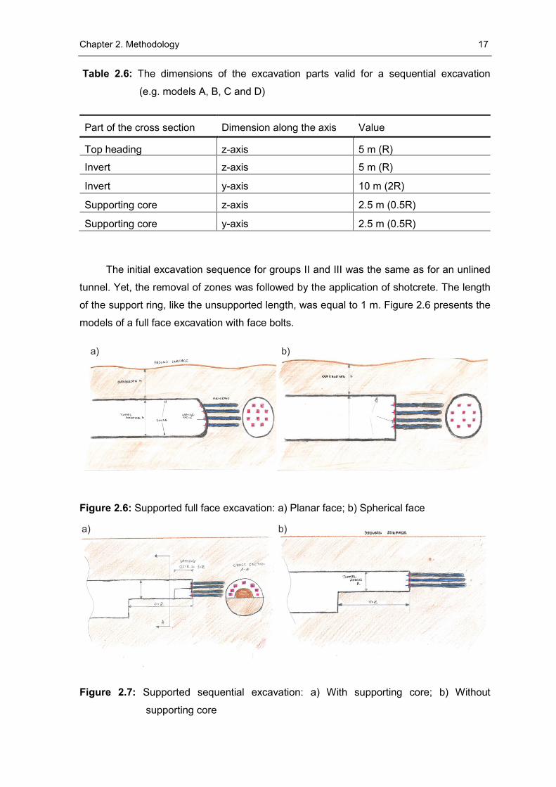
Table 2.6: The dimensions of the excavation parts valid for a sequential excavation
(e.g. models A, B, C and D)
Part of the cross section Dimension along the axis Value
Top heading z-axis 5 m (R)
Invert z-axis 5 m (R)
Invert y-axis 10 m (2R)
Supporting core z-axis 2.5 m (0.5R)
Supporting core y-axis 2.5 m (0.5R)
The initial excavation sequence for groups II and III was the same as for an unlined
tunnel. Yet, the removal of zones was followed by the application of shotcrete. The length
of the support ring, like the unsupported length, was equal to 1 m. Figure 2.6 presents the
models of a full face excavation with face bolts.
Figure 2.6: Supported full face excavation: a) Planar face; b) Spherical face
Figure 2.7: Supported sequential excavation: a) With supporting core; b) Without
supporting core
a) b)
a) b)
Chapter 2. Methodology 18
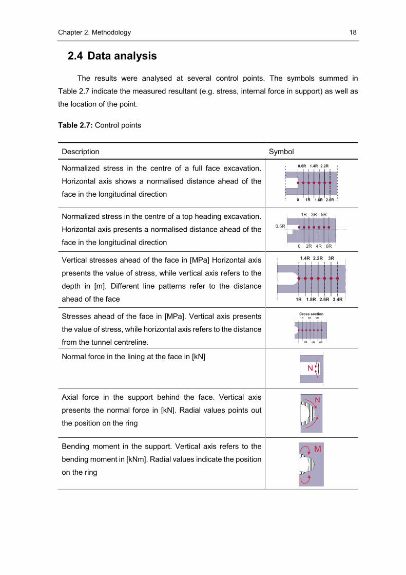
2.4 Data analysis
The results were analysed at several control points. The symbols summed in
Table 2.7 indicate the measured resultant (e.g. stress, internal force in support) as well as
the location of the point.
Table 2.7: Control points
Description Symbol
Normalized stress in the centre of a full face excavation.
Horizontal axis shows a normalised distance ahead of the
face in the longitudinal direction
Normalized stress in the centre of a top heading excavation.
Horizontal axis presents a normalised distance ahead of the
face in the longitudinal direction
Vertical stresses ahead of the face in [MPa] Horizontal axis
presents the value of stress, while vertical axis refers to the
depth in [m]. Different line patterns refer to the distance
ahead of the face
Stresses ahead of the face in [MPa]. Vertical axis presents
the value of stress, while horizontal axis refers to the distance
from the tunnel centreline.
Normal force in the lining at the face in [kN]
Axial force in the support behind the face. Vertical axis
presents the normal force in [kN]. Radial values points out
the position on the ring
Bending moment in the support. Vertical axis refers to the
bending moment in [kNm]. Radial values indicate the position
on the ring
N
Chapter 2. Methodology 19
2.5 Model validation
2.5.1 Secondary stress state
A plausibility check was carried out in order to establish if the developed script is
functioning correctly. Series of runs was performed using a slice of the chosen mesh. The
length of the slice along the y-axis accounted to one round length. The author compared
the numerically obtained stresses with the closed-form solution of Feder & Arwanitakis
(1976). In addition, analytical solution derived by Kolymbas (1998) was utilized to validate
the stresses ahead of the face. However, in the second test the limitations of the solution
required an assumption of a hydrostatic stress state.
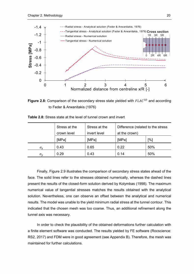
Figure 2.8 presents the comparison of radial and tangential stresses at the tunnel
sidewall. Secondary stresses (vertical axis) are plotted against the normalized distance from
the tunnel centreline (horizontal axis). Firstly, both solutions suggest the existence of a
plastic zone around the excavation. Notice that the peak tangential stress obtained by the
closed-form solution is approximately 10% higher than the result yielded with 𝐹𝐿𝐴𝐶3𝐷.
Furthermore, the location of the maximum tangential stress is slightly shifted. In the
remaining course of stresses one can observe a constant difference in the values.
There are several possible explanation of the fact that stress states are not coherent.
Firstly, Itasca (2017) states that the fixed model boundaries are responsible for stresses to
be underestimated. Secondly, the difference may be caused by an assumption of a constant
stress state by the solution of Feder & Arwanitakis (1976). Especially in case of shallow
tunnels, this assumption may be incorrect. The reason for that is a relative increase of
stresses with depth. To be specific, Table 2.8 shows the stress state at the level of the
crown and invert. As the data points out, the change of stresses between the crown and the
invert amounts to 50% of the stress state at the crown. Finally, the model width may be too
short. The closed-form solution of Feder & Arwanitakis (1976) yields the initial stress state
only 12R away from the tunnel centreline. However, numerical model with a comparable
width would either cause an increase of the computational time or require a coarser mesh
discretization. This was not desired. Furthermore, the accuracy of the results obtained in
the longitudinal direction was of primary interest.
Chapter 2. Methodology 20
Figure 2.8: Comparison of the secondary stress state yielded with 𝐹𝐿𝐴𝐶3𝐷 and according
to Feder & Arwanitakis (1976)
Table 2.8: Stress state at the level of tunnel crown and invert
Stress at the
crown level
Stress at the
invert level
Difference (related to the stress
at the crown)
[MPa] [MPa] [MPa] [%]
𝜎𝑧 0.43 0.65 0.22 50%
𝜎𝑦 0.29 0.43 0.14 50%
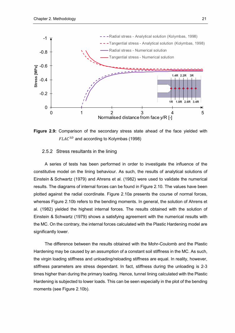
Finally, Figure 2.9 illustrates the comparison of secondary stress states ahead of the
face. The solid lines refer to the stresses obtained numerically, whereas the dashed lines
present the results of the closed-form solution derived by Kolymbas (1998). The maximum
numerical value of tangential stresses matches the results obtained with the analytical
solution. Nevertheless, one can observe an offset between the analytical and numerical
results. The model was unable to the yield minimum radial stress at the tunnel contour. This
indicated that the chosen mesh was too coarse. Thus, an additional refinement along the
tunnel axis was necessary.
In order to check the plausibility of the obtained deformations further calculation with
a finite element software was conducted. The results yielded by FE software (Rocscience:
RS2, 2017) and FDM were in good agreement (see Appendix B). Therefore, the mesh was
maintained for further calculations.
-1.4
-1.2
-1
-0.8
-0.6
-0.4
-0.2
0
0 1 2 3 4 5 6Normalized distance from centreline x/R [-]
Radial stress - Analytical solution (Feder & Arwanitakis, 1976)
Tangential stress - Analytical solution (Feder & Arwanitakis, 1976)
Radial stress - Numerical solution
Tangential stress - Numerical solution
Chapter 2. Methodology 21
Figure 2.9: Comparison of the secondary stress state ahead of the face yielded with
𝐹𝐿𝐴𝐶3𝐷 and according to Kolymbas (1998)
2.5.2 Stress resultants in the lining
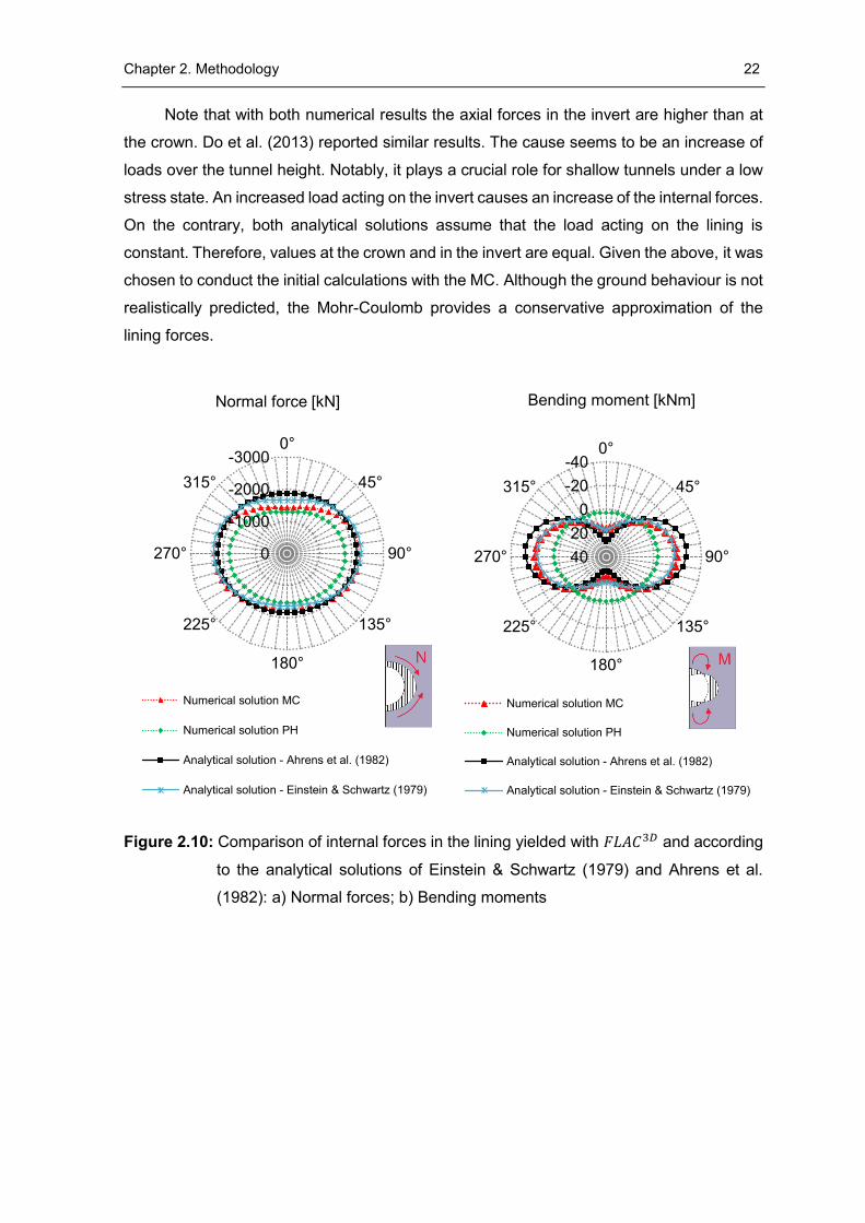
A series of tests has been performed in order to investigate the influence of the
constitutive model on the lining behaviour. As such, the results of analytical solutions of
Einstein & Schwartz (1979) and Ahrens et al. (1982) were used to validate the numerical
results. The diagrams of internal forces can be found in Figure 2.10. The values have been
plotted against the radial coordinate. Figure 2.10a presents the course of normal forces,
whereas Figure 2.10b refers to the bending moments. In general, the solution of Ahrens et
al. (1982) yielded the highest internal forces. The results obtained with the solution of
Einstein & Schwartz (1979) shows a satisfying agreement with the numerical results with
the MC. On the contrary, the internal forces calculated with the Plastic Hardening model are
significantly lower.
The difference between the results obtained with the Mohr-Coulomb and the Plastic
Hardening may be caused by an assumption of a constant soil stiffness in the MC. As such,
the virgin loading stiffness and unloading/reloading stiffness are equal. In reality, however,
stiffness parameters are stress dependant. In fact, stiffness during the unloading is 2-3
times higher than during the primary loading. Hence, tunnel lining calculated with the Plastic
Hardening is subjected to lower loads. This can be seen especially in the plot of the bending
moments (see Figure 2.10b).
-1
-0.8
-0.6
-0.4
-0.2
00 1 2 3 4 5
Normalised distance from face y/R [-]
Radial stress - Analytical solution (Kolymbas, 1998)
Tangential stress - Analytical solution (Kolymbas, 1998)
Radial stress - Numerical solution
Tangential stress - Numerical solution
Chapter 2. Methodology 22
Note that with both numerical results the axial forces in the invert are higher than at
the crown. Do et al. (2013) reported similar results. The cause seems to be an increase of
loads over the tunnel height. Notably, it plays a crucial role for shallow tunnels under a low
stress state. An increased load acting on the invert causes an increase of the internal forces.
On the contrary, both analytical solutions assume that the load acting on the lining is
constant. Therefore, values at the crown and in the invert are equal. Given the above, it was
chosen to conduct the initial calculations with the MC. Although the ground behaviour is not
realistically predicted, the Mohr-Coulomb provides a conservative approximation of the
lining forces.
Figure 2.10: Comparison of internal forces in the lining yielded with 𝐹𝐿𝐴𝐶3𝐷 and according
to the analytical solutions of Einstein & Schwartz (1979) and Ahrens et al.
(1982): a) Normal forces; b) Bending moments
-3000
-2000
-1000
0
0°
45°
90°
135°
180°
225°
270°
315°
Normal force [kN]
Numerical solution MC
Numerical solution PH
Analytical solution - Ahrens et al. (1982)
Analytical solution - Einstein & Schwartz (1979)
-40
-20
0
20
40
0°
45°
90°
135°
180°
225°
270°
315°
Bending moment [kNm]
Numerical solution MC
Numerical solution PH
Analytical solution - Ahrens et al. (1982)
Analytical solution - Einstein & Schwartz (1979)
23
3 Results
3.1 Failure mechanism
The simulations in the following subsection have been performed with the parameter
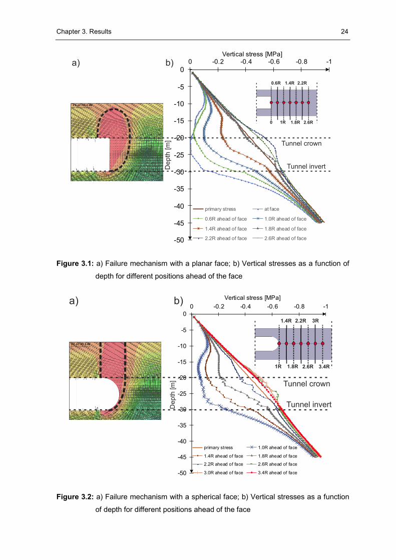
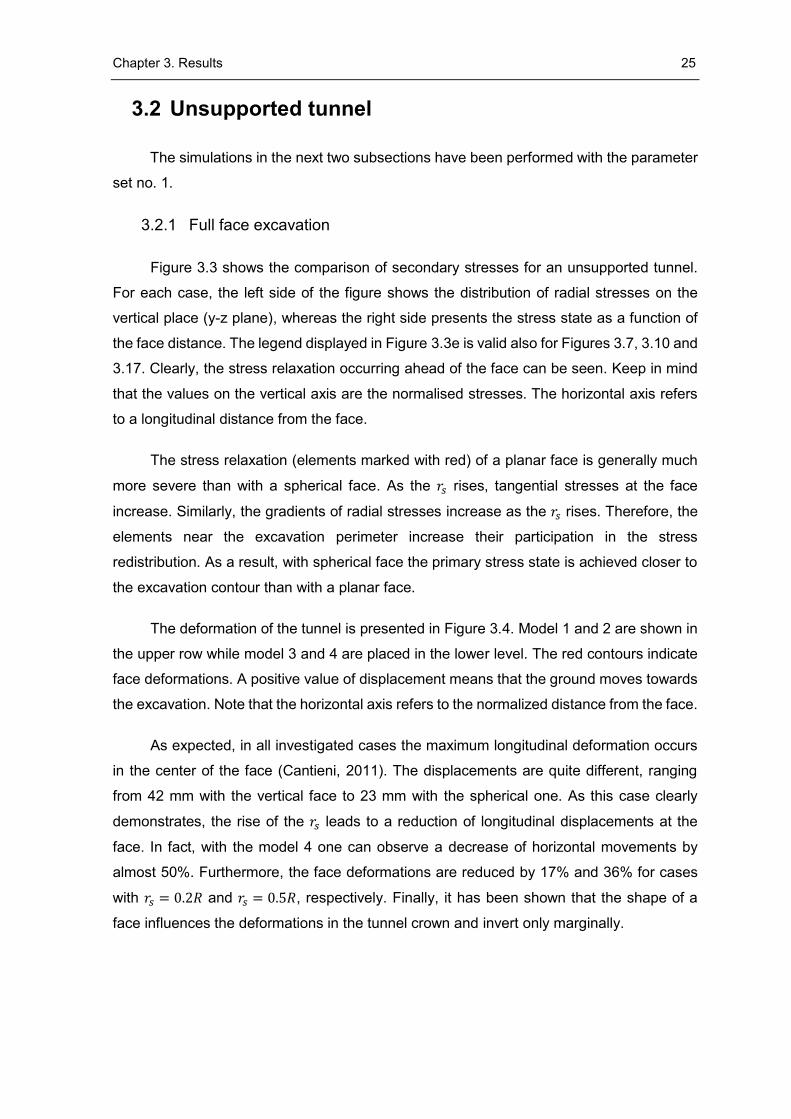
set no. 2. Figure 3.1b and Figure 3.2b present the vertical stresses ahead of the face.
Stresses have been plotted at different distances to the face to investigate the formation of
a load-bearing arch. The solid lines represent the primary vertical stress, whereas the
horizontal dashed lines refer to the levels of the crown and invert.
Turning our attention to the vertical face, a notable increase of vertical stresses takes
place between the positions 1.4R and 2.6R ahead of the face. However, in case of a
spherical face an equivalent increase of stresses occurs between the positions 1.8R and
3R. Those stress concentrations suggest a formation of the load-bearing arch. Though, as
previously anticipated by Kusumoto et al. (2013) and Shinji et al. (2004), with a spherical
face the arching appears closer to the excavation contour than with a vertical heading.
Apart from the change of the arch positions, different collapse mechanisms were
encountered (see Figure 3.1a and Figure 3.2a). The failure contours have been highlighted
with a dashed line. It can be observed that a planar face experiences a semi-circular failure.
A similar shape was already proposed by Krause (1987) and later confirmed by Schubert &
Schweiger (2004). The prism extends to 1.5R above the tunnel crown, whereas the wedge
ahead of the face expands horizontally by 1R. Turning our attention to a spherical face one
can observe a chimney-shaped failure. While the volume of the wedge is significantly lower
than with the vertical face, the prism extends to 4R above the crown. In case of a shallow
tunnel the prism may reach the ground surface. The most likely reason of this behaviour is
a greater unsupported length. Remember that with the planar face the unsupported span
was equal to 0.2R, whereas with the spherical face it can be assumed as 𝑟𝑠 (i.e. R).
Chapter 3. Results 24
Figure 3.1: a) Failure mechanism with a planar face; b) Vertical stresses as a function of
depth for different positions ahead of the face
Figure 3.2: a) Failure mechanism with a spherical face; b) Vertical stresses as a function
of depth for different positions ahead of the face
-50
-45
-40
-35
-30
-25
-20
-15
-10
-5
0-1-0.8-0.6-0.4-0.20
Vertical stress [MPa]
primary stress at face
0.6R ahead of face 1.0R ahead of face
1.4R ahead of face 1.8R ahead of face
2.2R ahead of face 2.6R ahead of face
Tunnel crown
Tunnel invertDep
th [
m]
a) b)
-50
-45
-40
-35
-30
-25
-20
-15
-10
-5
0
-1-0.8-0.6-0.4-0.20
Vertical stress [MPa]
primary stress 1.0R ahead of face
1.4R ahead of face 1.8R ahead of face
2.2R ahead of face 2.6R ahead of face
3.0R ahead of face 3.4R ahead of face
Tunnel crown
Tunnel invertDe
pth
[m
]
a) b)
Chapter 3. Results 25
3.2 Unsupported tunnel
The simulations in the next two subsections have been performed with the parameter
set no. 1.
3.2.1 Full face excavation
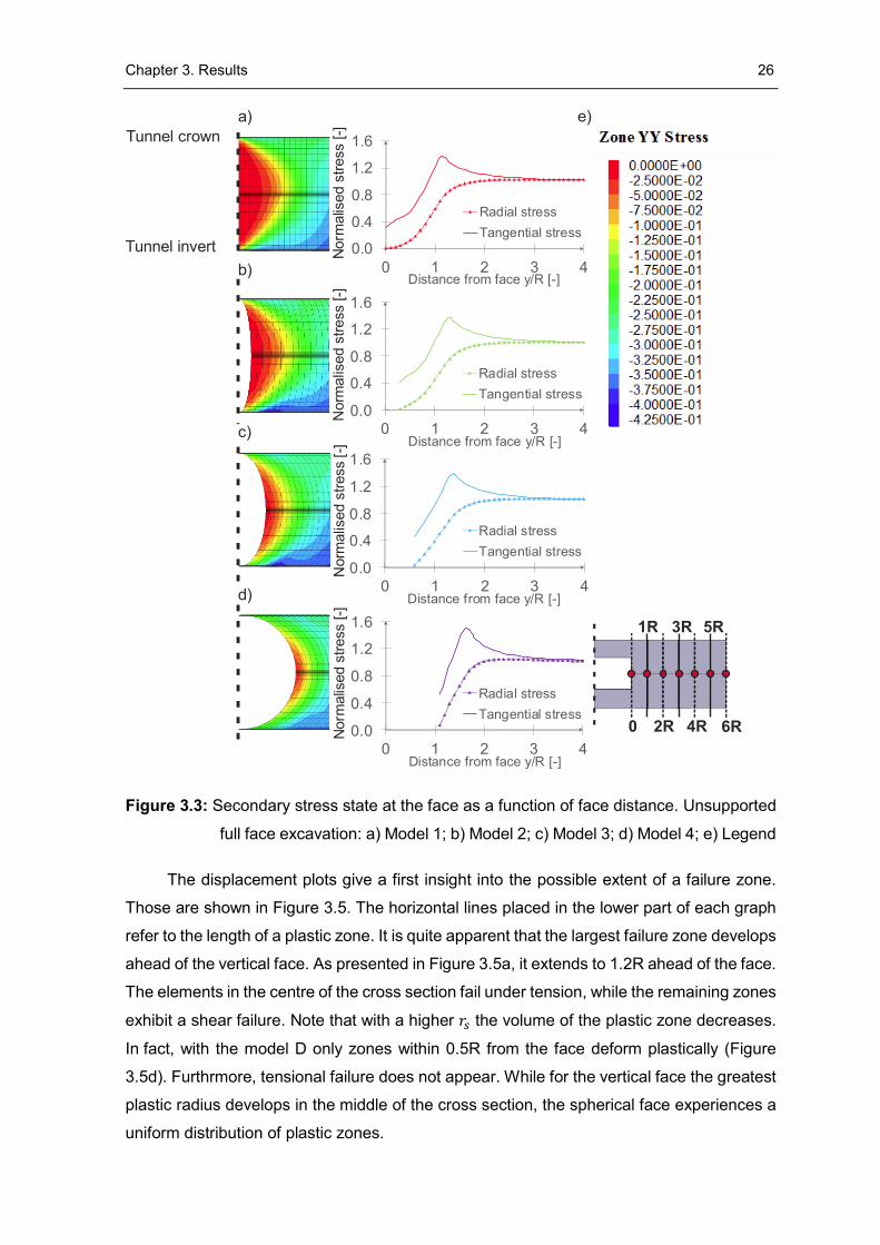
Figure 3.3 shows the comparison of secondary stresses for an unsupported tunnel.
For each case, the left side of the figure shows the distribution of radial stresses on the
vertical place (y-z plane), whereas the right side presents the stress state as a function of
the face distance. The legend displayed in Figure 3.3e is valid also for Figures 3.7, 3.10 and
3.17. Clearly, the stress relaxation occurring ahead of the face can be seen. Keep in mind
that the values on the vertical axis are the normalised stresses. The horizontal axis refers
to a longitudinal distance from the face.
The stress relaxation (elements marked with red) of a planar face is generally much
more severe than with a spherical face. As the 𝑟𝑠 rises, tangential stresses at the face
increase. Similarly, the gradients of radial stresses increase as the 𝑟𝑠 rises. Therefore, the
elements near the excavation perimeter increase their participation in the stress
redistribution. As a result, with spherical face the primary stress state is achieved closer to
the excavation contour than with a planar face.
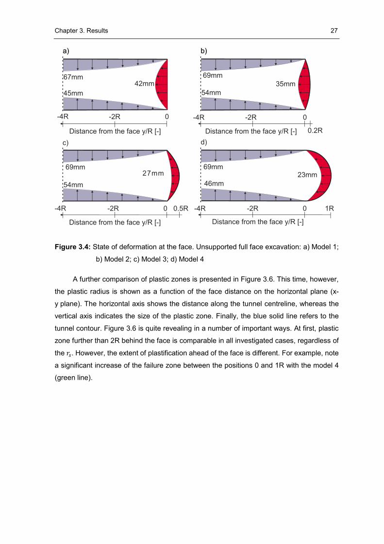
The deformation of the tunnel is presented in Figure 3.4. Model 1 and 2 are shown in
the upper row while model 3 and 4 are placed in the lower level. The red contours indicate
face deformations. A positive value of displacement means that the ground moves towards
the excavation. Note that the horizontal axis refers to the normalized distance from the face.
As expected, in all investigated cases the maximum longitudinal deformation occurs
in the center of the face (Cantieni, 2011). The displacements are quite different, ranging
from 42 mm with the vertical face to 23 mm with the spherical one. As this case clearly
demonstrates, the rise of the 𝑟𝑠 leads to a reduction of longitudinal displacements at the
face. In fact, with the model 4 one can observe a decrease of horizontal movements by
almost 50%. Furthermore, the face deformations are reduced by 17% and 36% for cases
with 𝑟𝑠 = 0.2𝑅 and 𝑟𝑠 = 0.5𝑅, respectively. Finally, it has been shown that the shape of a
face influences the deformations in the tunnel crown and invert only marginally.
Chapter 3. Results 26
Figure 3.3: Secondary stress state at the face as a function of face distance. Unsupported
full face excavation: a) Model 1; b) Model 2; c) Model 3; d) Model 4; e) Legend
The displacement plots give a first insight into the possible extent of a failure zone.
Those are shown in Figure 3.5. The horizontal lines placed in the lower part of each graph
refer to the length of a plastic zone. It is quite apparent that the largest failure zone develops
ahead of the vertical face. As presented in Figure 3.5a, it extends to 1.2R ahead of the face.
The elements in the centre of the cross section fail under tension, while the remaining zones
exhibit a shear failure. Note that with a higher 𝑟𝑠 the volume of the plastic zone decreases.
In fact, with the model D only zones within 0.5R from the face deform plastically (Figure
3.5d). Furthrmore, tensional failure does not appear. While for the vertical face the greatest
plastic radius develops in the middle of the cross section, the spherical face experiences a
uniform distribution of plastic zones.
0.0
0.4
0.8
1.2
1.6
0 1 2 3 4Distance from face y/R [-]
Radial stress
Tangential stress
0.0
0.4
0.8
1.2
1.6
0 1 2 3 4Distance from face y/R [-]
Radial stress
Tangential stress
0.0
0.4
0.8
1.2
1.6
0 1 2 3 4Distance from face y/R [-]
Radial stress
Tangential stress
a)
b)
c)
d)
Norm
alis
ed s
tress [-]
0.0
0.4
0.8
1.2
1.6
0 1 2 3 4Distance from face y/R [-]
Radial stress
Tangential stress
Norm
alis
ed s
tress [-]
Norm
alis
ed s
tress
[-]
Norm
alis
ed s
tress [-]
Tunnel crown
Tunnel invert
e)
Chapter 3. Results 27
Figure 3.4: State of deformation at the face. Unsupported full face excavation: a) Model 1;
b) Model 2; c) Model 3; d) Model 4
A further comparison of plastic zones is presented in Figure 3.6. This time, however,
the plastic radius is shown as a function of the face distance on the horizontal plane (x-
y plane). The horizontal axis shows the distance along the tunnel centreline, whereas the
vertical axis indicates the size of the plastic zone. Finally, the blue solid line refers to the
tunnel contour. Figure 3.6 is quite revealing in a number of important ways. At first, plastic
zone further than 2R behind the face is comparable in all investigated cases, regardless of
the 𝑟𝑠. However, the extent of plastification ahead of the face is different. For example, note
a significant increase of the failure zone between the positions 0 and 1R with the model 4
(green line).
Chapter 3. Results 28
Figure 3.5: Plastic state at the face. Unsupported full face excavation: a) Model 1;
b) Model 2; c) Model 3; d) Model 4
Figure 3.6: Plastic radius as a function of face distance. Unsupported full face excavation
a) b)
L=1.2R L=R
c) d)
L=0.8R L=0.5R
0
1
2
3
-3 -2 -1 0 1 2
r_s=0
r_s=0.2R
r_s=0.5R
r_s=R
Distance from the face y/R [-]
Pla
stic r
ad
ius x
/R [
-]
RExcavation
Chapter 3. Results 29
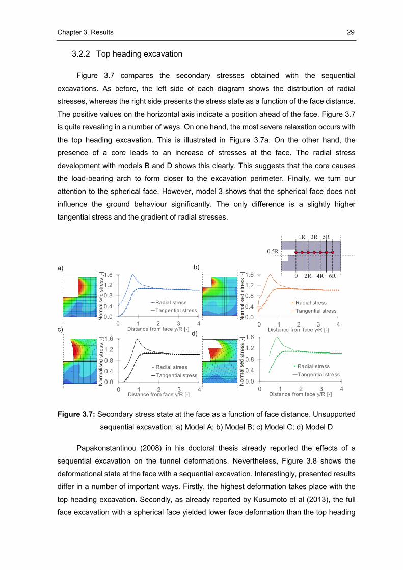
3.2.2 Top heading excavation
Figure 3.7 compares the secondary stresses obtained with the sequential
excavations. As before, the left side of each diagram shows the distribution of radial
stresses, whereas the right side presents the stress state as a function of the face distance.
The positive values on the horizontal axis indicate a position ahead of the face. Figure 3.7
is quite revealing in a number of ways. On one hand, the most severe relaxation occurs with
the top heading excavation. This is illustrated in Figure 3.7a. On the other hand, the
presence of a core leads to an increase of stresses at the face. The radial stress
development with models B and D shows this clearly. This suggests that the core causes
the load-bearing arch to form closer to the excavation perimeter. Finally, we turn our
attention to the spherical face. However, model 3 shows that the spherical face does not
influence the ground behaviour significantly. The only difference is a slightly higher
tangential stress and the gradient of radial stresses.
Figure 3.7: Secondary stress state at the face as a function of face distance. Unsupported
sequential excavation: a) Model A; b) Model B; c) Model C; d) Model D
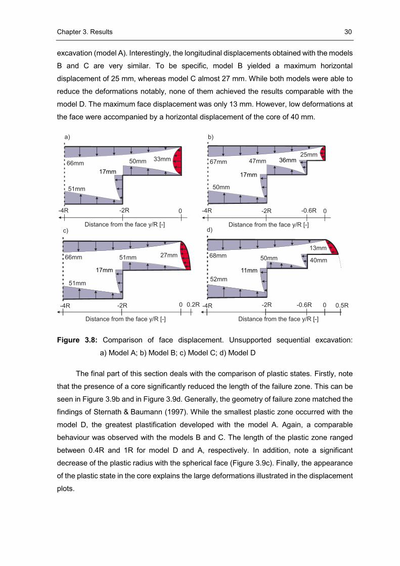
Papakonstantinou (2008) in his doctoral thesis already reported the effects of a
sequential excavation on the tunnel deformations. Nevertheless, Figure 3.8 shows the
deformational state at the face with a sequential excavation. Interestingly, presented results
differ in a number of important ways. Firstly, the highest deformation takes place with the
top heading excavation. Secondly, as already reported by Kusumoto et al (2013), the full
face excavation with a spherical face yielded lower face deformation than the top heading
0.0
0.4
0.8
1.2
1.6
0 1 2 3 4Distance from face y/R [-]
Radial stress
Tangential stress0.0
0.4
0.8
1.2
1.6
0 1 2 3 4Distance from face y/R [-]
Radial stress
Tangential stress
0.0
0.4
0.8
1.2
1.6
0 1 2 3 4Distance from face y/R [-]
Radial stress
Tangential stress0.0
0.4
0.8
1.2
1.6
0 1 2 3 4Distance f rom face y/R [-]
Radial stress
Tangential stress
a) b)
c)d)
No
rma
lise
d s
tre
ss [
-]N
orm
alise
d s
tre
ss [
-]
Norm
alised
str
ess [-]
No
rma
lised
str
ess [-]
Chapter 3. Results 30
excavation (model A). Interestingly, the longitudinal displacements obtained with the models
B and C are very similar. To be specific, model B yielded a maximum horizontal
displacement of 25 mm, whereas model C almost 27 mm. While both models were able to
reduce the deformations notably, none of them achieved the results comparable with the
model D. The maximum face displacement was only 13 mm. However, low deformations at
the face were accompanied by a horizontal displacement of the core of 40 mm.
Figure 3.8: Comparison of face displacement. Unsupported sequential excavation:
a) Model A; b) Model B; c) Model C; d) Model D
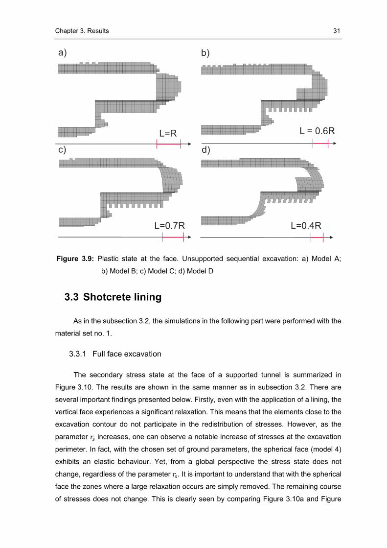
The final part of this section deals with the comparison of plastic states. Firstly, note
that the presence of a core significantly reduced the length of the failure zone. This can be
seen in Figure 3.9b and in Figure 3.9d. Generally, the geometry of failure zone matched the
findings of Sternath & Baumann (1997). While the smallest plastic zone occurred with the
model D, the greatest plastification developed with the model A. Again, a comparable
behaviour was observed with the models B and C. The length of the plastic zone ranged
between 0.4R and 1R for model D and A, respectively. In addition, note a significant
decrease of the plastic radius with the spherical face (Figure 3.9c). Finally, the appearance
of the plastic state in the core explains the large deformations illustrated in the displacement
plots.
Chapter 3. Results 31
Figure 3.9: Plastic state at the face. Unsupported sequential excavation: a) Model A;
b) Model B; c) Model C; d) Model D
3.3 Shotcrete lining
As in the subsection 3.2, the simulations in the following part were performed with the
material set no. 1.
3.3.1 Full face excavation
The secondary stress state at the face of a supported tunnel is summarized in
Figure 3.10. The results are shown in the same manner as in subsection 3.2. There are
several important findings presented below. Firstly, even with the application of a lining, the
vertical face experiences a significant relaxation. This means that the elements close to the
excavation contour do not participate in the redistribution of stresses. However, as the
parameter 𝑟𝑠 increases, one can observe a notable increase of stresses at the excavation
perimeter. In fact, with the chosen set of ground parameters, the spherical face (model 4)
exhibits an elastic behaviour. Yet, from a global perspective the stress state does not
change, regardless of the parameter 𝑟𝑠. It is important to understand that with the spherical
face the zones where a large relaxation occurs are simply removed. The remaining course
of stresses does not change. This is clearly seen by comparing Figure 3.10a and Figure
b)
c)
L=R
L=0.4R
a)
d)
L = 0.6R
L=0.7R
Chapter 3. Results 32
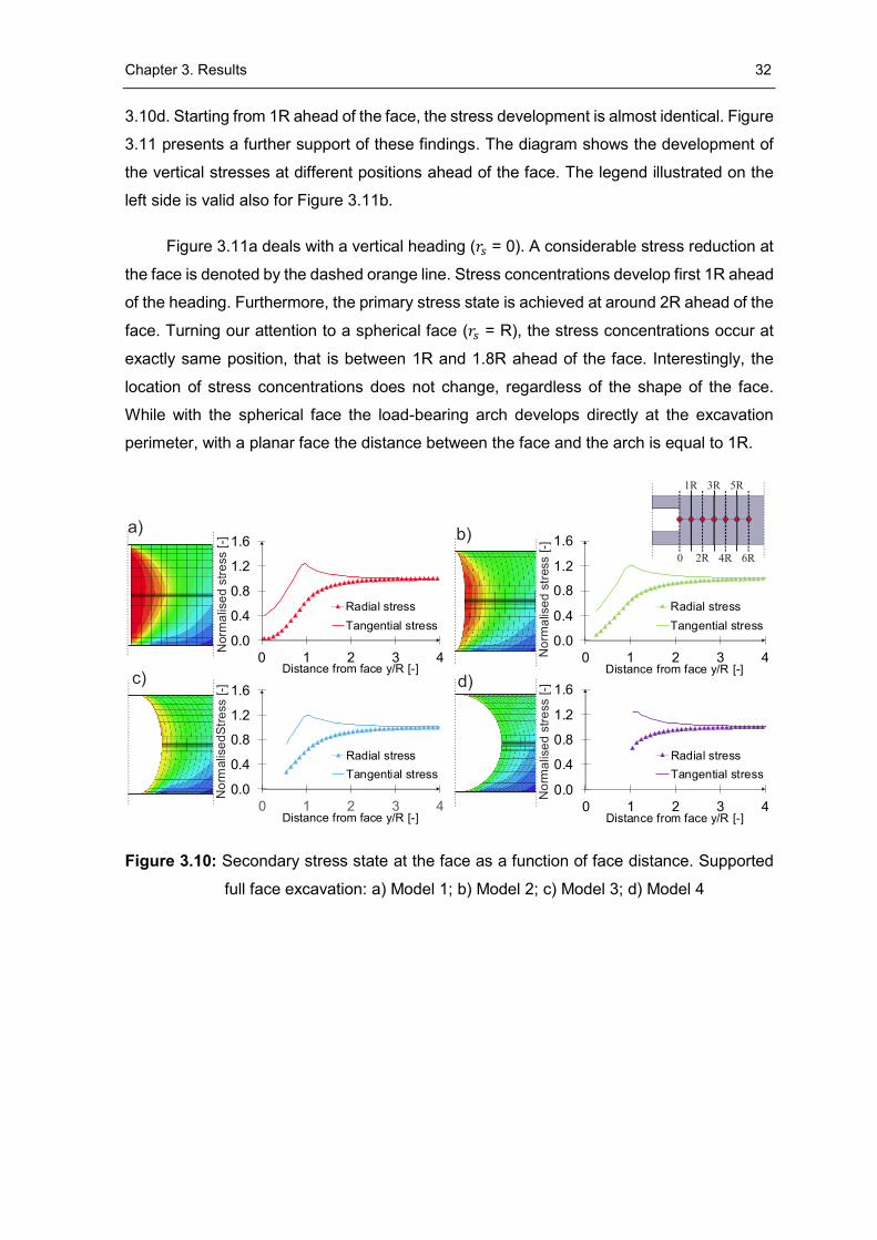
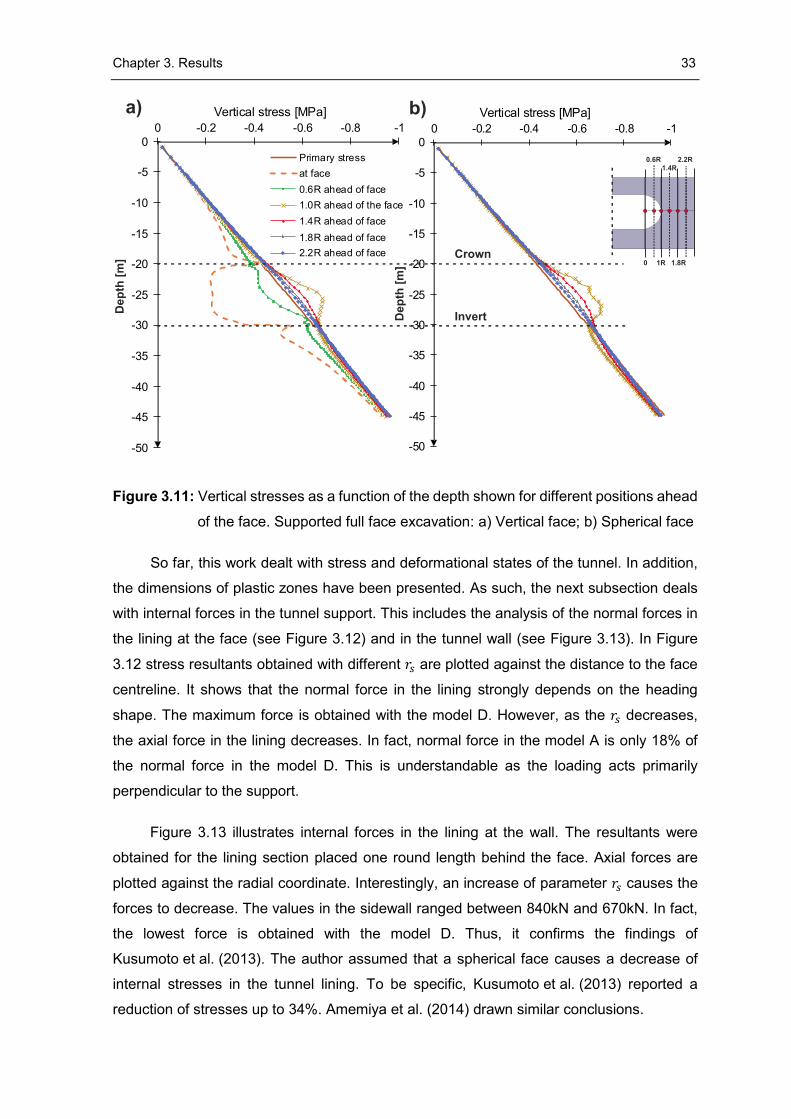
3.10d. Starting from 1R ahead of the face, the stress development is almost identical. Figure
3.11 presents a further support of these findings. The diagram shows the development of
the vertical stresses at different positions ahead of the face. The legend illustrated on the
left side is valid also for Figure 3.11b.
Figure 3.11a deals with a vertical heading (𝑟𝑠 = 0). A considerable stress reduction at
the face is denoted by the dashed orange line. Stress concentrations develop first 1R ahead
of the heading. Furthermore, the primary stress state is achieved at around 2R ahead of the
face. Turning our attention to a spherical face (𝑟𝑠 = R), the stress concentrations occur at
exactly same position, that is between 1R and 1.8R ahead of the face. Interestingly, the
location of stress concentrations does not change, regardless of the shape of the face.
While with the spherical face the load-bearing arch develops directly at the excavation
perimeter, with a planar face the distance between the face and the arch is equal to 1R.
Figure 3.10: Secondary stress state at the face as a function of face distance. Supported
full face excavation: a) Model 1; b) Model 2; c) Model 3; d) Model 4
0.0
0.4
0.8
1.2
1.6
0 1 2 3 4Distance from face y/R [-]
Radial stress
Tangential stress
0.0
0.4
0.8
1.2
1.6
0 1 2 3 4Distance from face y/R [-]
Radial stress
Tangential stress
0.0
0.4
0.8
1.2
1.6
0 1 2 3 4Distance from face y/R [-]
Radial stress
Tangential stress
0.0
0.4
0.8
1.2
1.6
0 1 2 3 4Distance from face y/R [-]
Radial stress
Tangential stress
a) b)
c) d)
No
rmalis
ed
Str
ess [
-]N
orm
alis
ed s
tre
ss [
-]
No
rma
lise
d s
tress [-]
No
rma
lise
d s
tre
ss [
-]
Chapter 3. Results 33
Figure 3.11: Vertical stresses as a function of the depth shown for different positions ahead
of the face. Supported full face excavation: a) Vertical face; b) Spherical face
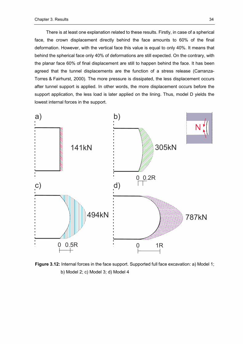
So far, this work dealt with stress and deformational states of the tunnel. In addition,
the dimensions of plastic zones have been presented. As such, the next subsection deals
with internal forces in the tunnel support. This includes the analysis of the normal forces in
the lining at the face (see Figure 3.12) and in the tunnel wall (see Figure 3.13). In Figure
3.12 stress resultants obtained with different 𝑟𝑠 are plotted against the distance to the face
centreline. It shows that the normal force in the lining strongly depends on the heading
shape. The maximum force is obtained with the model D. However, as the 𝑟𝑠 decreases,
the axial force in the lining decreases. In fact, normal force in the model A is only 18% of
the normal force in the model D. This is understandable as the loading acts primarily
perpendicular to the support.
Figure 3.13 illustrates internal forces in the lining at the wall. The resultants were
obtained for the lining section placed one round length behind the face. Axial forces are
plotted against the radial coordinate. Interestingly, an increase of parameter 𝑟𝑠 causes the
forces to decrease. The values in the sidewall ranged between 840kN and 670kN. In fact,
the lowest force is obtained with the model D. Thus, it confirms the findings of
Kusumoto et al. (2013). The author assumed that a spherical face causes a decrease of
internal stresses in the tunnel lining. To be specific, Kusumoto et al. (2013) reported a
reduction of stresses up to 34%. Amemiya et al. (2014) drawn similar conclusions.
-50
-45
-40
-35
-30
-25
-20
-15
-10
-5
0-1-0.8-0.6-0.4-0.20
Vertical stress [MPa]
-50
-45
-40
-35
-30
-25
-20
-15
-10
-5
0
-1-0.8-0.6-0.4-0.20
Vertical stress [MPa]
Primary stress
at face
0.6R ahead of face
1.0R ahead of the face
1.4R ahead of face
1.8R ahead of face
2.2R ahead of face
Chapter 3. Results 34
There is at least one explanation related to these results. Firstly, in case of a spherical
face, the crown displacement directly behind the face amounts to 60% of the final
deformation. However, with the vertical face this value is equal to only 40%. It means that
behind the spherical face only 40% of deformations are still expected. On the contrary, with
the planar face 60% of final displacement are still to happen behind the face. It has been
agreed that the tunnel displacements are the function of a stress release (Carranza-
Torres & Fairhurst, 2000). The more pressure is dissipated, the less displacement occurs
after tunnel support is applied. In other words, the more displacement occurs before the
support application, the less load is later applied on the lining. Thus, model D yields the
lowest internal forces in the support.
Figure 3.12: Internal forces in the face support. Supported full face excavation: a) Model 1;
b) Model 2; c) Model 3; d) Model 4
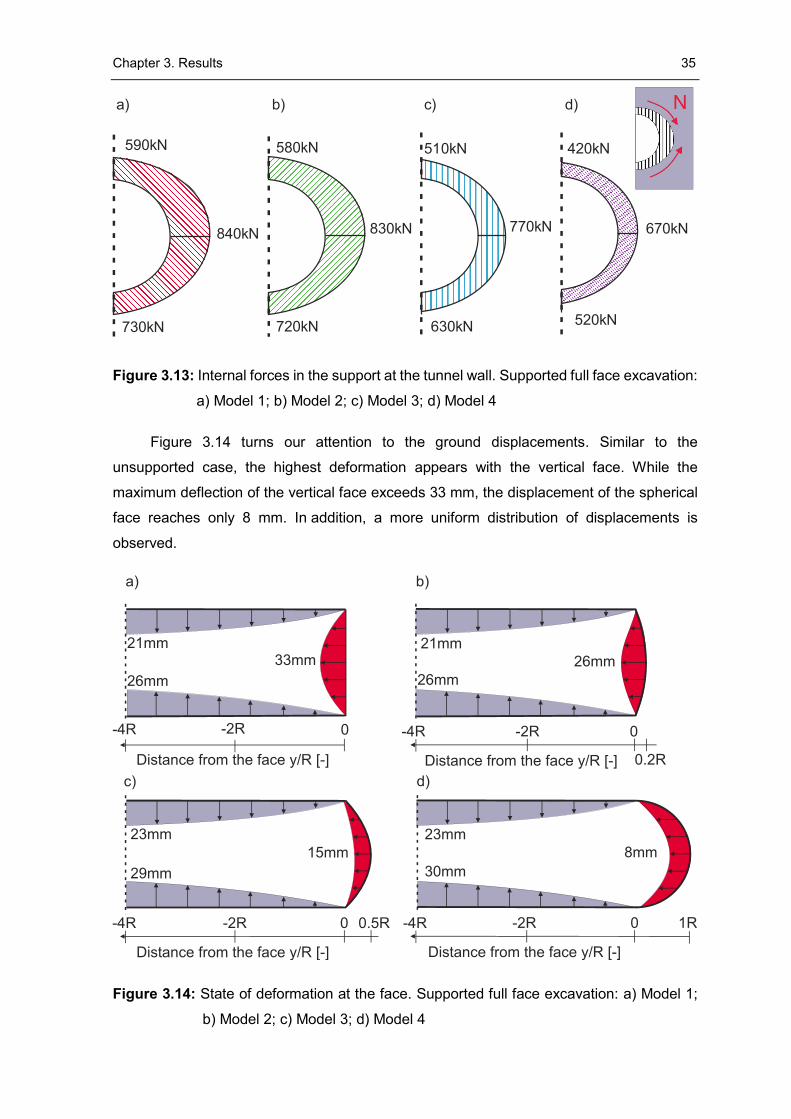
Chapter 3. Results 35
Figure 3.13: Internal forces in the support at the tunnel wall. Supported full face excavation:
a) Model 1; b) Model 2; c) Model 3; d) Model 4
Figure 3.14 turns our attention to the ground displacements. Similar to the
unsupported case, the highest deformation appears with the vertical face. While the
maximum deflection of the vertical face exceeds 33 mm, the displacement of the spherical
face reaches only 8 mm. In addition, a more uniform distribution of displacements is
observed.
Figure 3.14: State of deformation at the face. Supported full face excavation: a) Model 1;
b) Model 2; c) Model 3; d) Model 4
840kN
590kN
730kN
830kN
580kN
720kN
770kN
510kN
630kN
670kN
420kN
520kN
a) b) c) d)
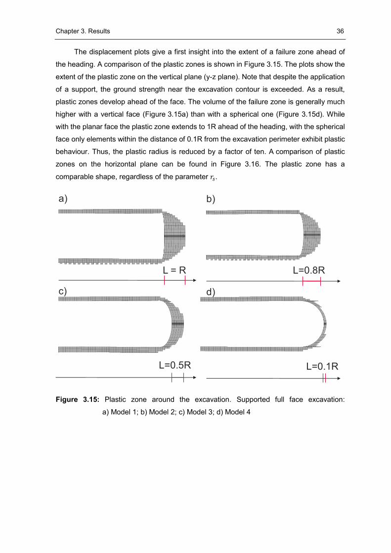
Chapter 3. Results 36
The displacement plots give a first insight into the extent of a failure zone ahead of
the heading. A comparison of the plastic zones is shown in Figure 3.15. The plots show the
extent of the plastic zone on the vertical plane (y-z plane). Note that despite the application
of a support, the ground strength near the excavation contour is exceeded. As a result,
plastic zones develop ahead of the face. The volume of the failure zone is generally much
higher with a vertical face (Figure 3.15a) than with a spherical one (Figure 3.15d). While
with the planar face the plastic zone extends to 1R ahead of the heading, with the spherical
face only elements within the distance of 0.1R from the excavation perimeter exhibit plastic
behaviour. Thus, the plastic radius is reduced by a factor of ten. A comparison of plastic
zones on the horizontal plane can be found in Figure 3.16. The plastic zone has a
comparable shape, regardless of the parameter 𝑟𝑠.
Figure 3.15: Plastic zone around the excavation. Supported full face excavation:
a) Model 1; b) Model 2; c) Model 3; d) Model 4
a) b)
c) d)
L = R L=0.8R
L=0.5R L=0.1R
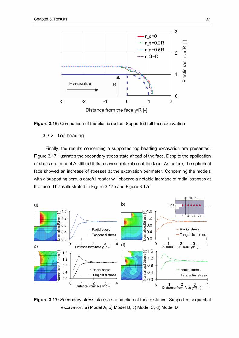
Chapter 3. Results 37
Figure 3.16: Comparison of the plastic radius. Supported full face excavation
3.3.2 Top heading
Finally, the results concerning a supported top heading excavation are presented.
Figure 3.17 illustrates the secondary stress state ahead of the face. Despite the application
of shotcrete, model A still exhibits a severe relaxation at the face. As before, the spherical
face showed an increase of stresses at the excavation perimeter. Concerning the models
with a supporting core, a careful reader will observe a notable increase of radial stresses at
the face. This is illustrated in Figure 3.17b and Figure 3.17d.
Figure 3.17: Secondary stress states as a function of face distance. Supported sequential
excavation: a) Model A; b) Model B; c) Model C; d) Model D
0
1
2
3
-3 -2 -1 0 1 2
r_s=0
r_s=0.2R
r_s=0.5R
r_S=R
Distance from the face y/R [-]
Pla
stic r
adiu
s x
/R [
-]
RExcavation
0.0
0.4
0.8
1.2
1.6
0 1 2 3 4Distance from face y/R [-]
Radial stress
Tangential stress0.0
0.4
0.8
1.2
1.6
0 1 2 3 4Distance from face y/R [-]
Radial stress
Tangential stress
0.0
0.4
0.8
1.2
1.6
0 1 2 3 4Distance from face y/R [-]
Radial stress
Tangential stress
0.0
0.4
0.8
1.2
1.6
0 1 2 3 4Distance from face y/R [-]
Radial stress
Tangential stress
a) b)
c) d)
Norm
alis
ed
Str
ess [
-]N
orm
alis
ed
Str
ess [-]
Norm
alis
ed
Str
ess [
- ]N
orm
alis
ed S
tre
ss [- ]
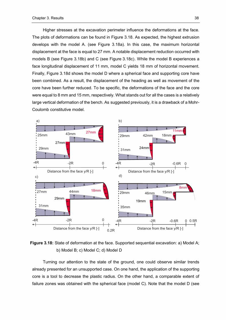
Chapter 3. Results 38
Higher stresses at the excavation perimeter influence the deformations at the face.
The plots of deformations can be found in Figure 3.18. As expected, the highest extrusion
develops with the model A. (see Figure 3.18a). In this case, the maximum horizontal
displacement at the face is equal to 27 mm. A notable displacement reduction occurred with
models B (see Figure 3.18b) and C (see Figure 3.18c). While the model B experiences a
face longitudinal displacement of 11 mm, model C yields 18 mm of horizontal movement.
Finally, Figure 3.18d shows the model D where a spherical face and supporting core have
been combined. As a result, the displacement of the heading as well as movement of the
core have been further reduced. To be specific, the deformations of the face and the core
were equal to 8 mm and 15 mm, respectively. What stands out for all the cases is a relatively
large vertical deformation of the bench. As suggested previously, it is a drawback of a Mohr-
Coulomb constitutive model.
Figure 3.18: State of deformation at the face. Supported sequential excavation: a) Model A;
b) Model B; c) Model C; d) Model D
Turning our attention to the state of the ground, one could observe similar trends
already presented for an unsupported case. On one hand, the application of the supporting
core is a tool to decrease the plastic radius. On the other hand, a comparable extent of
failure zones was obtained with the spherical face (model C). Note that the model D (see
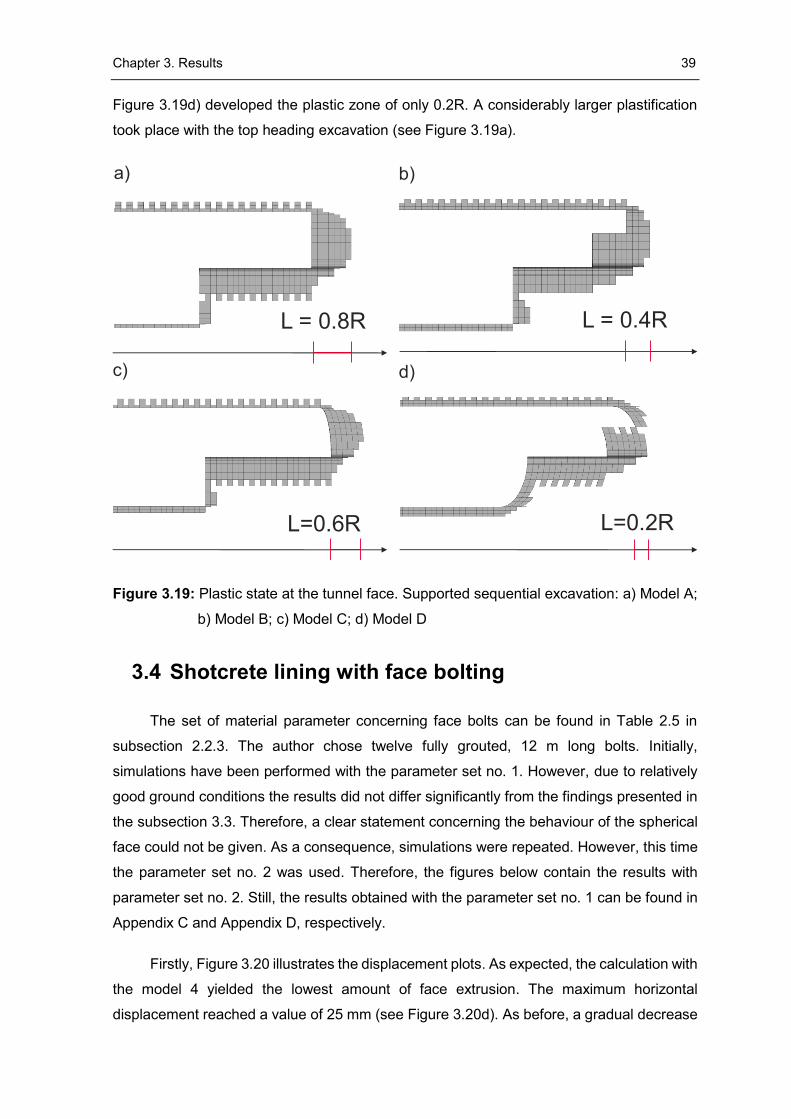
Chapter 3. Results 39
Figure 3.19d) developed the plastic zone of only 0.2R. A considerably larger plastification
took place with the top heading excavation (see Figure 3.19a).
Figure 3.19: Plastic state at the tunnel face. Supported sequential excavation: a) Model A;
b) Model B; c) Model C; d) Model D
3.4 Shotcrete lining with face bolting
The set of material parameter concerning face bolts can be found in Table 2.5 in
subsection 2.2.3. The author chose twelve fully grouted, 12 m long bolts. Initially,
simulations have been performed with the parameter set no. 1. However, due to relatively
good ground conditions the results did not differ significantly from the findings presented in
the subsection 3.3. Therefore, a clear statement concerning the behaviour of the spherical
face could not be given. As a consequence, simulations were repeated. However, this time
the parameter set no. 2 was used. Therefore, the figures below contain the results with
parameter set no. 2. Still, the results obtained with the parameter set no. 1 can be found in
Appendix C and Appendix D, respectively.
Firstly, Figure 3.20 illustrates the displacement plots. As expected, the calculation with
the model 4 yielded the lowest amount of face extrusion. The maximum horizontal
displacement reached a value of 25 mm (see Figure 3.20d). As before, a gradual decrease
L = 0.8R
L=0.6R
L = 0.4R
L=0.2R
a) b)
c) d)
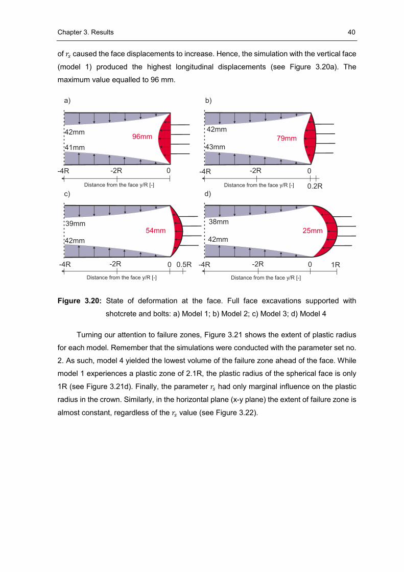
Chapter 3. Results 40
of 𝑟𝑠 caused the face displacements to increase. Hence, the simulation with the vertical face
(model 1) produced the highest longitudinal displacements (see Figure 3.20a). The
maximum value equalled to 96 mm.
Figure 3.20: State of deformation at the face. Full face excavations supported with
shotcrete and bolts: a) Model 1; b) Model 2; c) Model 3; d) Model 4
Turning our attention to failure zones, Figure 3.21 shows the extent of plastic radius
for each model. Remember that the simulations were conducted with the parameter set no.
2. As such, model 4 yielded the lowest volume of the failure zone ahead of the face. While
model 1 experiences a plastic zone of 2.1R, the plastic radius of the spherical face is only
1R (see Figure 3.21d). Finally, the parameter 𝑟𝑠 had only marginal influence on the plastic
radius in the crown. Similarly, in the horizontal plane (x-y plane) the extent of failure zone is
almost constant, regardless of the 𝑟𝑠 value (see Figure 3.22).
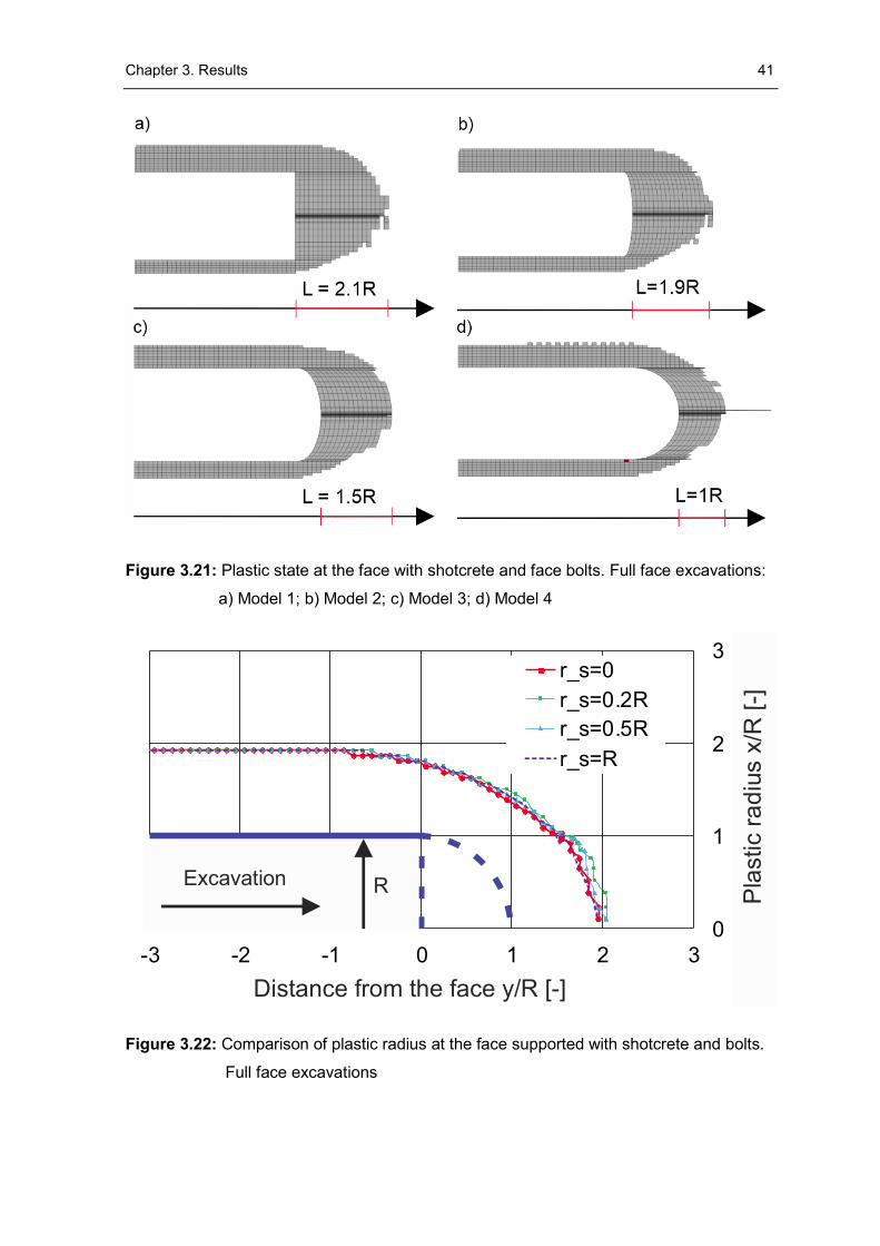
Chapter 3. Results 41
Figure 3.21: Plastic state at the face with shotcrete and face bolts. Full face excavations:
a) Model 1; b) Model 2; c) Model 3; d) Model 4
Figure 3.22: Comparison of plastic radius at the face supported with shotcrete and bolts.
Full face excavations
0
1
2
3
-3 -2 -1 0 1 2 3
r_s=0
r_s=0.2R
r_s=0.5R
r_s=R
Distance from the face y/R [-]
RExcavation
Pla
stic r
ad
ius x
/R [-]
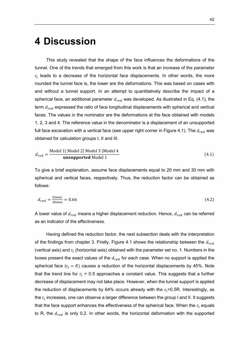
42
4 Discussion
This study revealed that the shape of the face influences the deformations of the
tunnel. One of the trends that emerged from this work is that an increase of the parameter
𝑟𝑠 leads to a decrease of the horizontal face displacements. In other words, the more
rounded the tunnel face is, the lower are the deformations. This was based on cases with
and without a tunnel support. In an attempt to quantitatively describe the impact of a
spherical face, an additional parameter 𝑑𝑟𝑒𝑑 was developed. As illustrated in Eq. (4.1), the
term 𝑑𝑟𝑒𝑑 expressed the ratio of face longitudinal displacements with spherical and vertical
faces. The values in the nominator are the deformations at the face obtained with models
1, 2, 3 and 4. The reference value in the denominator is a displacement of an unsupported
full face excavation with a vertical face (see upper right corner in Figure 4.1). The 𝑑𝑟𝑒𝑑 was
obtained for calculation groups I, II and III.
𝑑𝑟𝑒𝑑 =Model 1| Model 2| Model 3 |Model 4
𝐮𝐧𝐬𝐮𝐩𝐩𝐨𝐫𝐭𝐞𝐝 Model 1 (4.1)
To give a brief explanation, assume face displacements equal to 20 mm and 30 mm with
spherical and vertical faces, respectively. Thus, the reduction factor can be obtained as
follows:
𝑑𝑟𝑒𝑑 =20𝑚𝑚
30𝑚𝑚= 0.66 (4.2)
A lower value of 𝑑𝑟𝑒𝑑 means a higher displacement reduction. Hence, 𝑑𝑟𝑒𝑑 can be referred
as an indicator of the effectiveness.
Having defined the reduction factor, the next subsection deals with the interpretation
of the findings from chapter 3. Firstly, Figure 4.1 shows the relationship between the 𝑑𝑟𝑒𝑑
(vertical axis) and 𝑟𝑠 (horizontal axis) obtained with the parameter set no. 1. Numbers in the
boxes present the exact values of the 𝑑𝑟𝑒𝑑 for each case. When no support is applied the
spherical face (𝑟𝑠 = 𝑅) causes a reduction of the horizontal displacements by 45%. Note
that the trend line for 𝑟𝑠 > 0.5 approaches a constant value. This suggests that a further
decrease of displacement may not take place. However, when the tunnel support is applied
the reduction of displacements by 64% occurs already with the 𝑟𝑠=0.5R. Interestingly, as
the 𝑟𝑠 increases, one can observe a larger difference between the group I and II. It suggests
that the face support enhances the effectiveness of the spherical face. When the 𝑟𝑠 equals
to R, the 𝑑𝑟𝑒𝑑 is only 0.2. In other words, the horizontal deformation with the supported
Chapter 4. Discussion 43
spherical face equals to 20% of an equivalent displacement with an unsupported vertical
face.
Finally, the green circular points illustrate the reduction factor obtained for the group
III. As explained previously, it represents an excavation supported with a shotcrete and face
bolts. Comparing to the cases with shotcrete only, face bolting helps to further reduce the
displacements. Hence, the 𝑑𝑟𝑒𝑑 for group III is lower than for group II. However, as the 𝑟𝑠
increases, the difference between the green (group III) and the red line (group II) reduces.
There are at least two explanations related to these results. In general, the effect of face
bolting can be understood as a support pressure applied on the face. One on hand, the
support pressure is a function of shear stresses at the interface between the ground and
the grout (Anagnostou & Serafeimidis, 2007). On the other hand, shear stresses are
influenced by the relative displacement between the bolt and the ground. As this work
already shown, the spherical face experiences significantly lower face deformations than
the vertical one. Lower deformations lead to a decrease of shear stresses along the
tensioned element. This means that a higher parameter 𝑟𝑠, leads to a lower support pressure
developed by bolts. The second explanation may involve the ground characteristics. Due to
the assumption of relatively good ground conditions, the calculations with groups II and III
yielded similar results. The values of the 𝑑𝑟𝑒𝑑 obtained with the parameter set no. 2 can be
found in Appendix E.
Turning our attention to a sequential excavation, Eq. (4.3) shows the formula for 𝑑𝑟𝑒𝑑.
Values in the numerator refer to a horizontal displacement at the face obtained for models
B, C or D, whereas the denominator is a reference displacement obtained with an
unsupported top heading excavation (see upper right corner in Figure 4.2).
𝑑𝑟𝑒𝑑 =Model B | Model C | Model D
𝐮𝐧𝐬𝐮𝐩𝐩𝐨𝐫𝐭𝐞𝐝 Model A (4.3)
The bar chart in Figure 4.2 illustrates the reduction factor 𝑑𝑟𝑒𝑑 of a sequential
excavation. It is shown that the application of a supporting core reduces the displacements
at the face by 24%. However, when the lining is applied, the reduction factor equals only
0.33. Interestingly, the reduction factors of the supported model A and unsupported model
C are equal. Similarly, model D without support yielded only slightly higher displacements
than the model B with face support. Finally, note that model D yields the lowest 𝑑𝑟𝑒𝑑. The
values of 𝑑𝑟𝑒𝑑 for unlined and lined tunnels equal to 0.39 and 0.24, respectively.
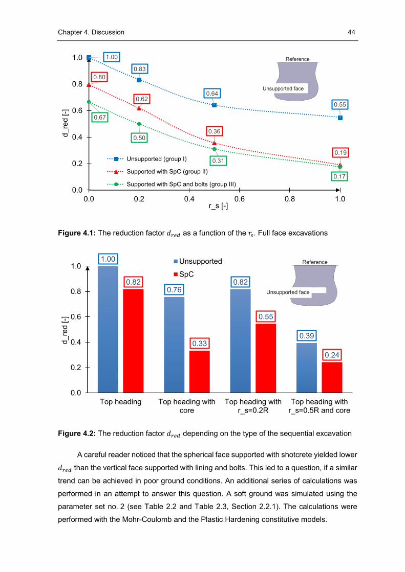
Chapter 4. Discussion 44
Figure 4.1: The reduction factor 𝑑𝑟𝑒𝑑 as a function of the 𝑟𝑠. Full face excavations
Figure 4.2: The reduction factor 𝑑𝑟𝑒𝑑 depending on the type of the sequential excavation
A careful reader noticed that the spherical face supported with shotcrete yielded lower
𝑑𝑟𝑒𝑑 than the vertical face supported with lining and bolts. This led to a question, if a similar
trend can be achieved in poor ground conditions. An additional series of calculations was
performed in an attempt to answer this question. A soft ground was simulated using the
parameter set no. 2 (see Table 2.2 and Table 2.3, Section 2.2.1). The calculations were
performed with the Mohr-Coulomb and the Plastic Hardening constitutive models.
1.00
0.83
0.64
0.55
0.80
0.62
0.36
0.19
0.67
0.50
0.31
0.17
0.0
0.2
0.4
0.6
0.8
1.0
0.0 0.2 0.4 0.6 0.8 1.0
d_re
d [-]
r_s [-]
Unsupported (group I)
Supported with SpC (group II)
Supported with SpC and bolts (group III)
1.00
0.760.82
0.39
0.82
0.33
0.55
0.24
0.0
0.2
0.4
0.6
0.8
1.0
Top heading Top heading withcore
Top heading withr_s=0.2R
Top heading withr_s=0.5R and core
d_re
d [-]
Unsupported
SpC
Reference
Unsupported face
Reference
Unsupported face
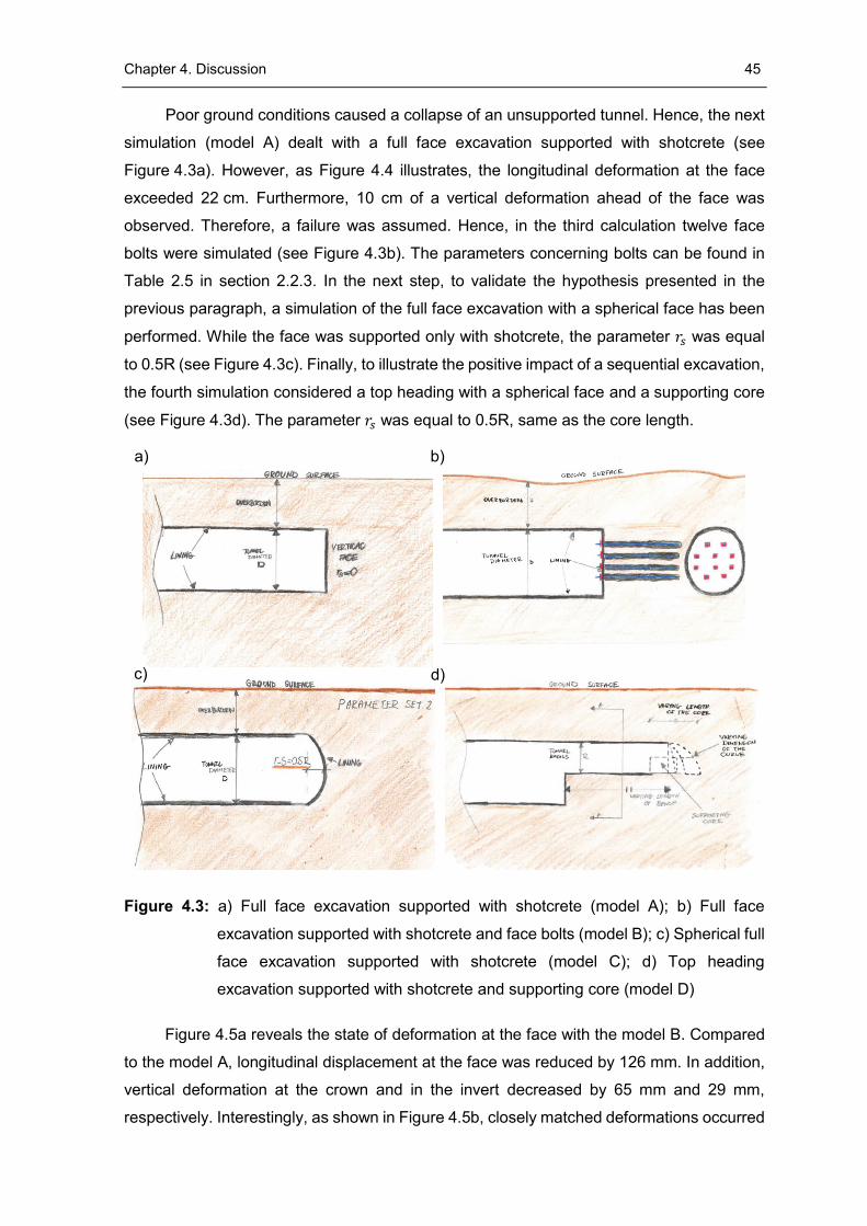
Chapter 4. Discussion 45
Poor ground conditions caused a collapse of an unsupported tunnel. Hence, the next
simulation (model A) dealt with a full face excavation supported with shotcrete (see
Figure 4.3a). However, as Figure 4.4 illustrates, the longitudinal deformation at the face
exceeded 22 cm. Furthermore, 10 cm of a vertical deformation ahead of the face was
observed. Therefore, a failure was assumed. Hence, in the third calculation twelve face
bolts were simulated (see Figure 4.3b). The parameters concerning bolts can be found in
Table 2.5 in section 2.2.3. In the next step, to validate the hypothesis presented in the
previous paragraph, a simulation of the full face excavation with a spherical face has been
performed. While the face was supported only with shotcrete, the parameter 𝑟𝑠 was equal
to 0.5R (see Figure 4.3c). Finally, to illustrate the positive impact of a sequential excavation,
the fourth simulation considered a top heading with a spherical face and a supporting core
(see Figure 4.3d). The parameter 𝑟𝑠 was equal to 0.5R, same as the core length.
Figure 4.3: a) Full face excavation supported with shotcrete (model A); b) Full face
excavation supported with shotcrete and face bolts (model B); c) Spherical full
face excavation supported with shotcrete (model C); d) Top heading
excavation supported with shotcrete and supporting core (model D)
Figure 4.5a reveals the state of deformation at the face with the model B. Compared
to the model A, longitudinal displacement at the face was reduced by 126 mm. In addition,
vertical deformation at the crown and in the invert decreased by 65 mm and 29 mm,
respectively. Interestingly, as shown in Figure 4.5b, closely matched deformations occurred
a) b)
c) d)
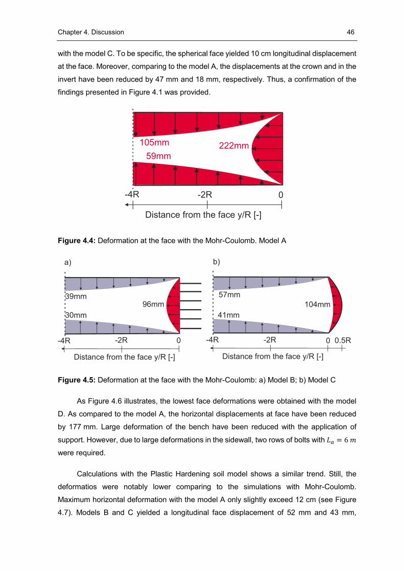
Chapter 4. Discussion 46
with the model C. To be specific, the spherical face yielded 10 cm longitudinal displacement
at the face. Moreover, comparing to the model A, the displacements at the crown and in the
invert have been reduced by 47 mm and 18 mm, respectively. Thus, a confirmation of the
findings presented in Figure 4.1 was provided.
Figure 4.4: Deformation at the face with the Mohr-Coulomb. Model A
Figure 4.5: Deformation at the face with the Mohr-Coulomb: a) Model B; b) Model C
As Figure 4.6 illustrates, the lowest face deformations were obtained with the model
D. As compared to the model A, the horizontal displacements at face have been reduced
by 177 mm. Large deformation of the bench have been reduced with the application of
support. However, due to large deformations in the sidewall, two rows of bolts with 𝐿𝑎 = 6 𝑚
were required.
Calculations with the Plastic Hardening soil model shows a similar trend. Still, the
deformatios were notably lower comparing to the simulations with Mohr-Coulomb.
Maximum horizontal deformation with the model A only slightly exceed 12 cm (see Figure
4.7). Models B and C yielded a longitudinal face displacement of 52 mm and 43 mm,
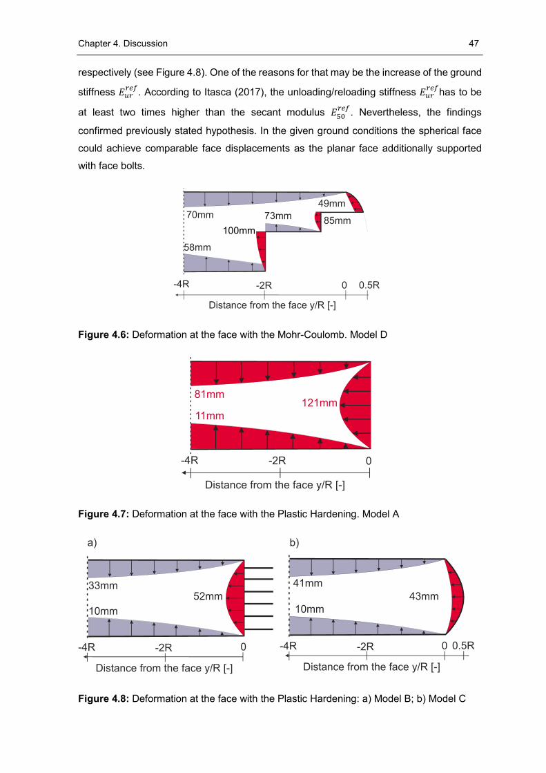
Chapter 4. Discussion 47
respectively (see Figure 4.8). One of the reasons for that may be the increase of the ground
stiffness 𝐸𝑢𝑟𝑟𝑒𝑓
. According to Itasca (2017), the unloading/reloading stiffness 𝐸𝑢𝑟𝑟𝑒𝑓
has to be
at least two times higher than the secant modulus 𝐸50𝑟𝑒𝑓
. Nevertheless, the findings
confirmed previously stated hypothesis. In the given ground conditions the spherical face
could achieve comparable face displacements as the planar face additionally supported
with face bolts.
Figure 4.6: Deformation at the face with the Mohr-Coulomb. Model D
Figure 4.7: Deformation at the face with the Plastic Hardening. Model A
Figure 4.8: Deformation at the face with the Plastic Hardening: a) Model B; b) Model C
48
5 Conclusion
5.1 Summary
This thesis was elaborated to compare the behaviour of planar and spherical faces in
the context of conventional tunnelling. To date there has been only few studies dealing
comprehensively with this topic. Therefore, the author made an attempt to combine the
analysis of secondary stresses and deformations. A particular emphasis was placed on the
development of the load-bearing arch ahead of the face. Collapse mechanisms as well as
the dimensions of failure zones have been compared. To achieve the objectives a series of
three-dimensional simulations using a FDM software was performed. The developed
models covered the range of staged and full face excavations.
The background of this work was provided in the introduction. Selected calculation
procedures, including failure mechanisms, have been presented. Finally, the author
summarized a number of studies which dealt with a spherical face to date.
Chapter 2 gave an insight into the methodology used in this thesis. As a part of this
section the model geometry, material parameters, boundary conditions and applied
constitutive models have been shown. In addition, the scope of the numerical analysis was
illustrated. Finally, the model validation confirmed that the developed programme yields
plausible results.
Chapter 3 dealt with the results of the numerical simulations. Firstly, this work
demonstrated that the application of the spherical face leads to a reduction of displacements
at the face. Secondly, the findings of this thesis suggested that the load-bearing arch
develops closer to the excavation contour than with a planar face. Thirdly, the simulations
with a tunnel support showed a decrease of lining forces with the spherical face. While the
stress state ahead of the heading was almost identical, face deformations were significantly
reduced. Finally, the volumes of plastic zones decreased.
Furthermore, it has been observed that the spherical face yields lower face
deformations than a top heading excavation with an auxiliary bench. Hence, the findings of
Kusumoto et al. (2013) have been confirmed. Still, the positive impact of a staged
excavation on the tunnel deformations has been revealed. A careful reader noticed a
reduction of displacements ahead of the face. It was also shown that the supporting core
Chapter 5. Conclusion 49
enhances the stability of the face. Interestingly, with the spherical face a comparable state
of deformation can be achieved as with the vertical face supported with a core.
Finally, using a dimensionless parameter 𝑑𝑟𝑒𝑑 it was possible to quantify the
effectiveness of the spherical face. In a soft ground the spherical face yielded similar
deformations as the vertical face supported with bolts. Hence, the necessity of bolts could
be eliminated. Even lower displacements occurred with the top heading excavation with a
spherical face. This method caused the reduction of face deformations by a factor of five.
Therefore, this excavation type is suitable for tunnelling in poor ground conditions. The lack
of face bolts accelerates the excavation process and reduces the material demands.
5.2 Outlook
Nevertheless, due to the number of important limitations this work does not exclude
further studies concerning a spherical tunnel face. Firstly, the conclusions stated in this work
are valid only for a homogeneous, isotropic ground. Secondly, a circular tunnel cross
section was assumed. Thirdly, a time-dependent behaviour of the tunnel support has not
been modelled. As such, the lining exhibited an elastic behaviour. This assumption,
however, does not comply with the reality. Finally, the majority of simulations have been
conducted with the Mohr-Coulomb constitutive model. As already mentioned, the constant
soil stiffness poses a significant drawback of this method. To summarize, further research
may explore the following topics:
Evaluation of the spherical face behaviour based on an example of a deep
tunnel with high in-situ stress level
Application of a high order constitutive model of tunnel lining. This could
include a simulation of a time-dependant behaviour (i.e. creep, strength and
stiffness increase)
Onsite feasibility study to determine an optimal value of the parameter 𝑟𝑠
Analysis of the cost-related subjects such as: material demand, number of
workforces, excavation machines
Analysis of the operational-related topics such as: excavation procedure in
poor ground conditions, time requirements and necessary modification of
excavation machines
Chapter 5. Conclusion 50
Behaviour of the spherical face with the other types of tunnel support such
as: pipe umbrella system, bolts, ground freezing or jet grouting
Investigation into the influence of geotechnical parameters on the reduction
factor 𝑑𝑟𝑒𝑑
51
Bibliography
Amemiya, K., Kakimi, K., Kusumoto, K. & Sasaki, T. 2014. Application of a spherical
tunnel face to full-face tunnel excavation by drill and blast. In: Proceedings of the 8th
Asian Rock Mechanics Symposium. Rock Mechanics for Global Issues – Natural
Disasters, Environment and Energy, Sapporo, Japan, 14.-16. October 2014.
Ahrens, H., Lindner, E. & Lux, K.-H. 1982. Zur Dimensionierung von Tunnelausbauten
nach den Empfehlungen zur Berechnung von Tunneln im Lockergestein.
Bautechnik 59, Heft 8, S.260-273
Anagnostou, G. & Serafeimidis, K. 2007. The dimensioning of tunnel face
reinforcement. In: Proceedings of ITA World Tunnel Congress 2007. Underground
Space – The 4th dimension of metropolises, Prague, Czech Republic, 5.-10. May
2007, Taylor & Francis Group: London.
Atkinson, J. H. & Potts, D. M. 1977. Stability of a shallow circular tunnel in cohesionless
soil. Géotechnique 27 (2), S. 203-2015
Atkinson, J. H. & Mair, R. J. 1981. Soil mechanics aspects of soft ground tunneling.
Ground Engineering 14 (5), S. 20-38
Broere, W. 2001. Tunnel face stability & New CPT applications. PhD thesis, Chair of
Underground Space Technology, Delft University of Technology, Netherlands.
Cantieni, L. 2011. Spatial Effects in Tunnelling Through Squeezing Ground. PhD thesis,
Institut für Geotechnik, ETH Zürich, Zürich, Switzerland
Carranza-Torres, C. & Fairhurst, C. 2000. Application of Convergence-Confinement
method of tunnel design to rock masses that satisfy the Hoek-Brown failure criterion.
Tunneling and Underground Space Technology 12 (2), S. 187-213
Do, N. A., Dias, D., Oreste, P. & Djeran-Maigre, I. 2013. Comparison between Design
Methods Applied to Segmental Tunnel Linings. Geotechnical Engineering Journal of
the SEAGS & AGSSEA. Vol. 44, December 2013.
Deutsche Gesellschaft für Geotechnik 2012. Empfehlung des Arbeitskreises “Numerik
in der Geotechnik” EANG. Verlag Ernst & Sohn: Berlin.
Einstein, H. H. & Schwartz, C. W. 1979. Simplified Analysis for Tunnel Supports. Journal
of the Geotechnical Engineering Division 105, S. 499-517.
Feder, G. & Arwanitakis, M. 1976. Zur Gebirgsmechanik ausbruchsnaher Bereiche
tiefliegender Hohlraumbauten (unter zentralsymmetrischer Belastung. Berg- und
Hüttenmännische Monatshefte, Jahrgang 121, Heft 4.
Bibliography 52
Golser, H. 2001. Die Anwendung der Methoder der finiten Element und Randelemente
im Tunnelbau. Dissertation, Institut für Felsmechanik und Tunnelbau, Technische
Universität Graz, Österreich.
Horn, N. 1961. Horizontaler Erdruck auf senkrechte Abschlussflächen von Tunnelröhren.
In: Landeskonferenz der ungarischen Tiefbauindustrie, Budapest, Hungary.
Itasca 2017. 𝐹𝐿𝐴𝐶3𝐷 6.0 Fast Lagrangian Analysis of Continua in 3 Dimensions. User’s
manual. Itasca Inc., Minneapolis, USA.
Jaky, J. 1944. The coefficient of earth pressure at rest. Journal for Society of Hungarian
Architects and Engineers, S. 355-358
Kirsch, A. 2015. Numerical investigation of the face stability of shallow tunnels in sand.
In: Proceedings of the 7th European Conference on Numerical Methods in
Geotechnical Engineering NUMGE 2010 – Numerical Methods in Geotechnical
Engineering, Benz, T. & Nordal, S. (eds.), Trondheim, Norway, 2.-4. June 2010,
S. 779-784. Taylor & Francis Group: London.
Kolymbas, D. 1998. Geotechnik – Tunnelbau und Tunnelmechanik. Eine systematische
Einführung mit besonderer Berücksichtigung mechanischer Probleme. Springer-
Verlag: Berlin, Heidelberg.
Krause, T. 1987. Schildvortrieb mit flüssigkeits- und erdgestützter Ortsbrust. In: Report
of the Institute of Geotechnical Engineering of the University of Braunschweig, No. 24.
Kusumoto, F., Tanimura, K. & Sato, J. 2013. The effect of hemi-spherical tunnel face
on the stability of mountain tunnels. In: Proceedings of the World Tunnel Congress -
Underground. The Way to the Future, Anagnostou, G. & Ehrbar, H. (eds.), Geneva,
Switzerland, May 31-June 7, 2013, S. 685-692. Taylor & Francis Group: London.
Leca, E. & Dormieux, L. 1990. Upper and lower bound solutions for the face stability of
shallow circular tunnels in frictional material. Géotechnique 40 (4), S. 581-606.
Meißner, H. 1991. Empfehlungen des Arbeitskreises „Numerik in der Geotechnik” der
Deutschen Gesellschaft für Erd- und Grundbau e.V. Geotechnik 14, S. 1-10.
Meißner, H. 1996. Tunnelbau unter Tage. Empfehlungen des Arbeitskreises 1.6
“Numerik in der Geotechnik”, Abschnitt 2, Geotechnik 19 (2),
Papakonstantinou, S. 2008. Technical and economical comparison between full face
and sequential excavation. Dissertation, Institut für Felsmechanik und Tunnelbau,
Technische Universität Graz, Österreich.
Rocscience: RS2 2017. User manual. Rocscience Inc., Ontario, USA
Bibliography 53
Ruse, N. M. 2004. Räumliche Betrachtung der Standsicherheit der Ortsbrust beim
Tunnelvortrieb. Dissertation, Institut für Geotechnik, Universität Stuttgart,
Deutschland.
Schubert, P. A. & Schweiger, H. F. 2004. Zur Standsicherheit der Ortsbrust in
Lockerböden. In: Proceedings of the ISRM regional symposium Eurock 2004 & 53rd
Geomechanics Colloquy - Rock Engineering. Theory and practice, Schubert, W. (ed.),
Salzburg, Austria, 6.-8. October 2004, S. 99-104. Verlag Glückauf: Essen.
Shinji, M., Morimoro, S. & Nakagawa K. 2004. Evaluation on the stability of tunnel face
in weak rock based on the three-dimensional numerical analysis. In: Proceedings of
the ISRM regional symposium Eurock 2004 & 53rd Geomechanics Colloquy - Rock
Engineering. Theory and practice, Schubert, W. (ed.), Salzburg, Austria, 6.-8. October
2004, S. 151-154. Verlag Glückauf: Essen.
Sternath, R. & Baumann, Th. 1997. Face support for tunnels in loose ground. In:
Tunnels for people: Proceedings of World Tunnel Congress ’97 and 23rd General
Assembly of the International Tunnelling Associations, Golser, J., Hinkel, W. &
Schubert, W. (eds.), Vienna, Austria, 12.-17. April 1997, S. 317-324. AA Balkema:
Rotterdam.
Wittke, W. 1999. Tunnelstatik Grundlagen: Geotechnik in Forschung und Praxis, WBI-
Print 4. S. 62-137. Verlag Glückauf: Essen.
Wittke, W. 1984. Felsmechanik – Grundlagen für wirtschaftliches Bauen im Fels.
Springer Verlag: Berlin, Heidelberg, New York, Tokyo.
Vermeer, P. A., Ruse, N. M. & Marcher, T. 2002. Tunnel Heading Stability in Drained
Ground. Felsbau 20 (6), S. 8-18.

54
Appendix
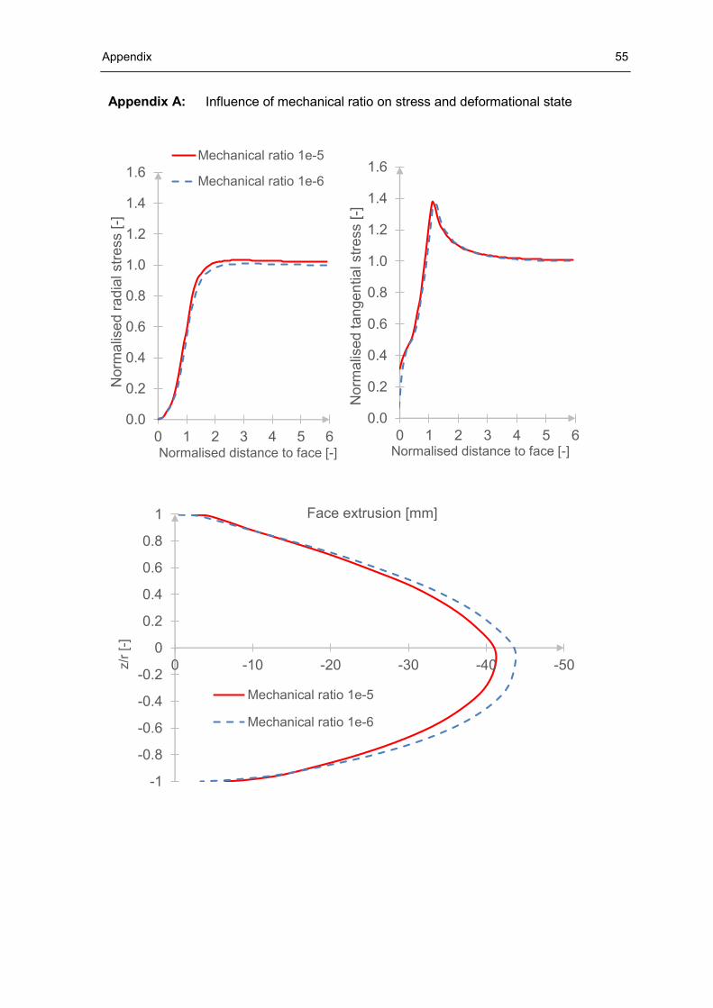
Appendix 55
Appendix A: Influence of mechanical ratio on stress and deformational state
0.0
0.2
0.4
0.6
0.8
1.0
1.2
1.4
1.6
0 1 2 3 4 5 6
Norm
alis
ed
rad
ial str
ess [
-]
Normalised distance to face [-]
Mechanical ratio 1e-5
Mechanical ratio 1e-6
0.0
0.2
0.4
0.6
0.8
1.0
1.2
1.4
1.6
0 1 2 3 4 5 6
No
rma
lise
d ta
nge
ntia
l str
ess [
-]
Normalised distance to face [-]
-1
-0.8
-0.6
-0.4
-0.2
0
0.2
0.4
0.6
0.8
1
-50-40-30-20-100z/r
[-]
Face extrusion [mm]
Mechanical ratio 1e-5
Mechanical ratio 1e-6
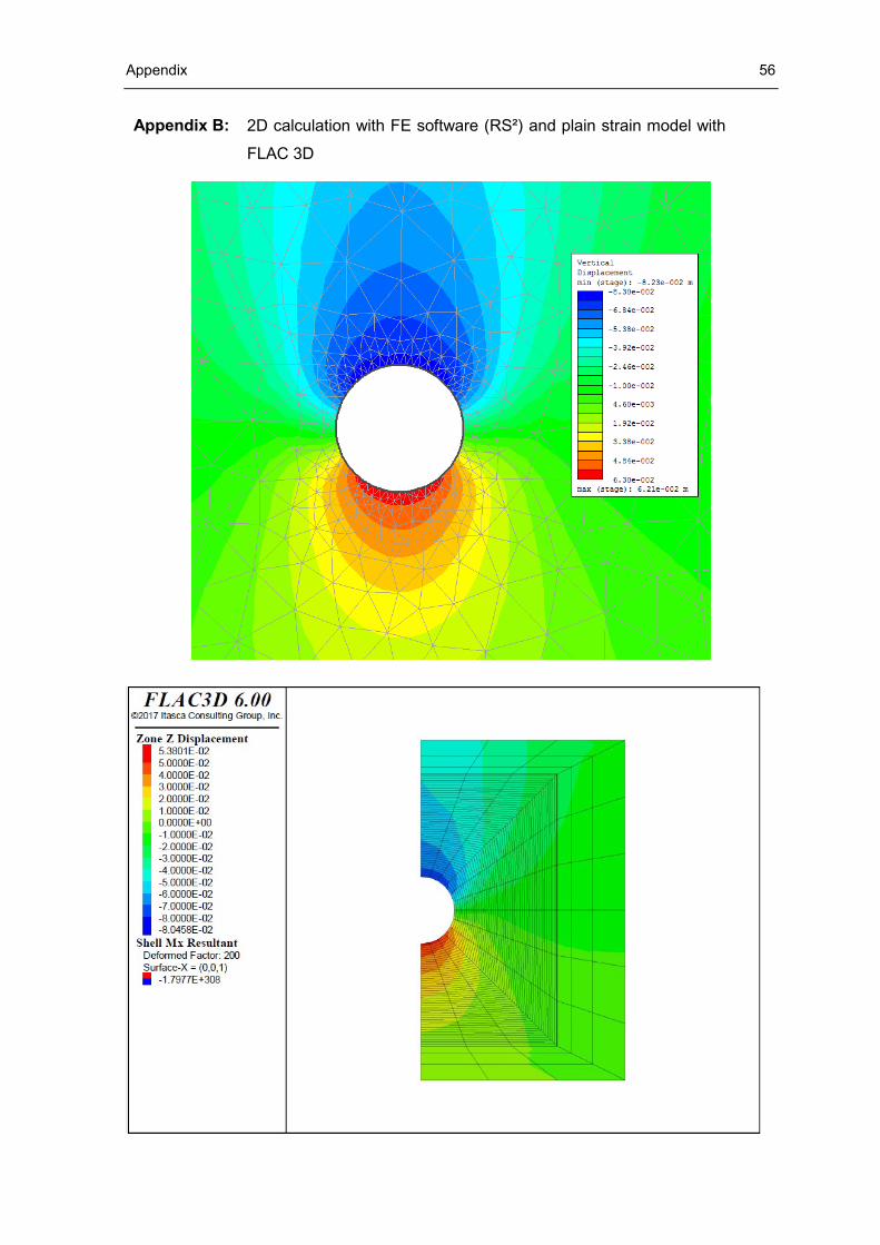
Appendix 56
Appendix B: 2D calculation with FE software (RS²) and plain strain model with
FLAC 3D
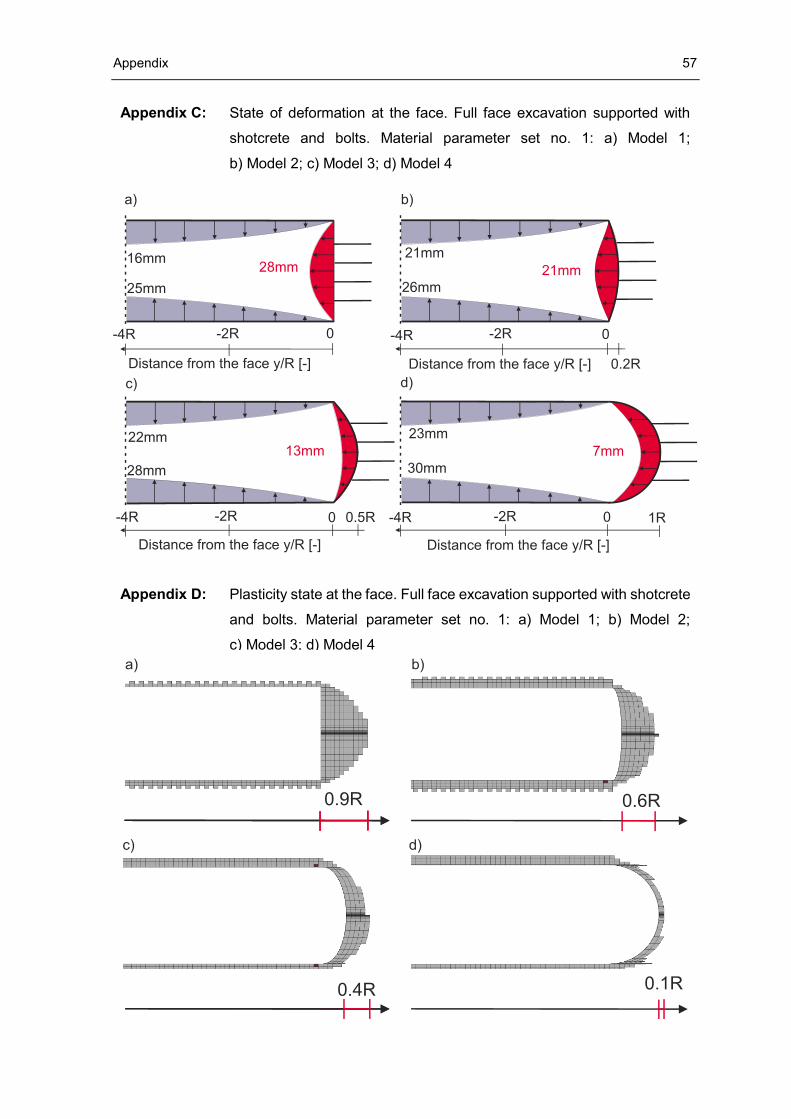
Appendix 57
Appendix C: State of deformation at the face. Full face excavation supported with
shotcrete and bolts. Material parameter set no. 1: a) Model 1;
b) Model 2; c) Model 3; d) Model 4
Appendix D: Plasticity state at the face. Full face excavation supported with shotcrete
and bolts. Material parameter set no. 1: a) Model 1; b) Model 2;
c) Model 3; d) Model 4
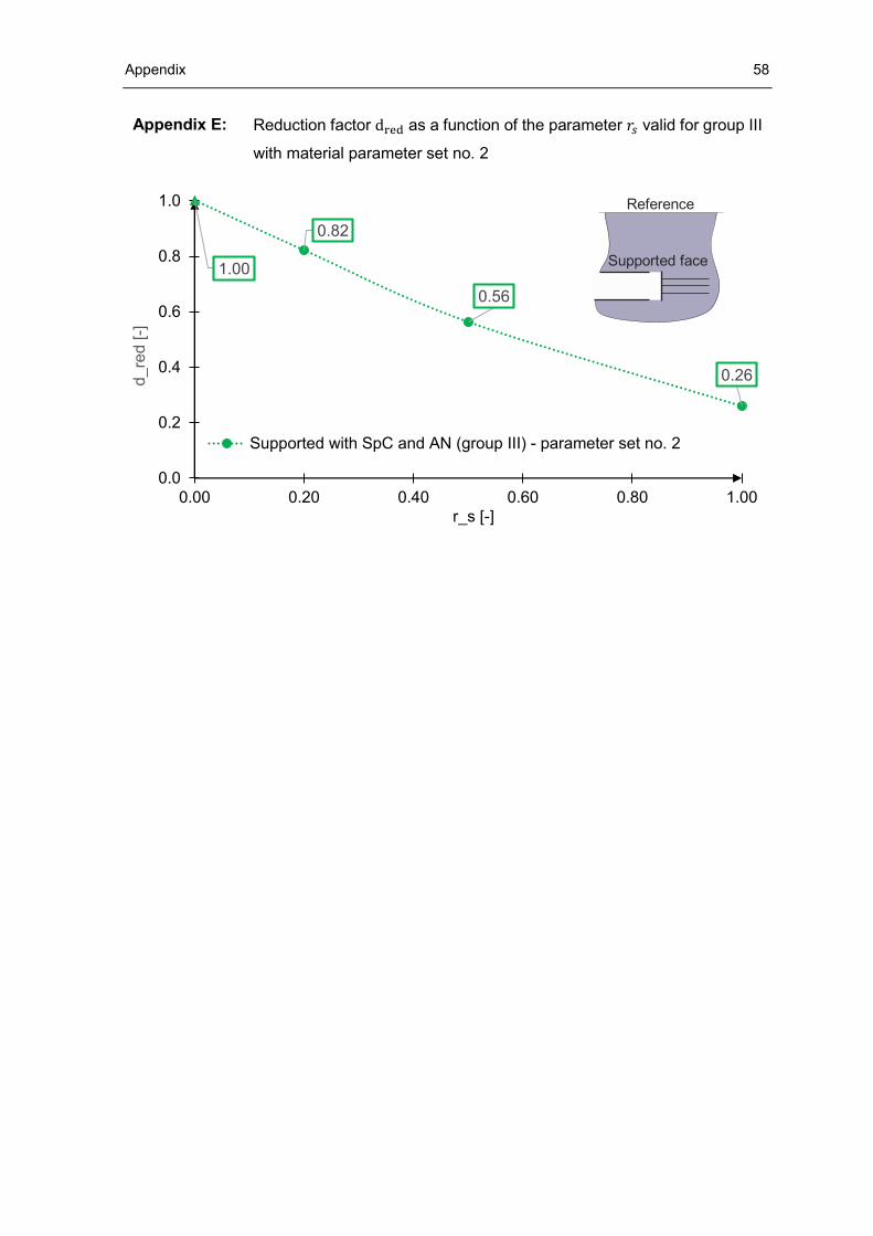
Appendix 58
Appendix E: Reduction factor dred as a function of the parameter 𝑟𝑠 valid for group III
with material parameter set no. 2
1.00
0.82
0.56
0.26
0.0
0.2
0.4
0.6
0.8
1.0
0.00 0.20 0.40 0.60 0.80 1.00
d_re
d [-]
r_s [-]
Supported with SpC and AN (group III) - parameter set no. 2
Reference
Supported face