Embed Size (px)
Citation preview
D3-4-A 2010: Extraktion von Architekturparametern a us dem IMA Standard und Synthese von IMA Konfigurationen
Version: 1.0
Projektbezeichnung SPES 2020
Verantwortlich Dr. Rupert Reiger
QS-Verantwortlich Dr. Stephan Stilkerich
Erstellt am 10/10/10 10:10
Zuletzt geändert 15.02.2011 22:13
Freigabestatus Vertraulich für Partner: Alle Partner
Projektöffentlich
X Öffentlich
Bearbeitungszustand in Bearbeitung
vorgelegt
X fertig gestellt
Weitere Produktinformationen
Erzeugung Dr. Rupert Reiger
Mitwirkend
Änderungsverzeichnis
Änderung Geänderte
Kapitel Beschreibung der Änderung Autor Zustand
Nr. Datum Versi
on
1 19/07/10 & folgende
Wochen
0.1 alle Initiale Produkterstellung, alle Belange zum Thema
sammeln
Reiger
In Bearbeitung
2 25/07/10 & folgende
Wochen
0.2 alle Literaturrecherche Reiger
In Bearbeitung
3 10/08/10 & folgende
Wochen
0.3 alle Stand der Technik Reiger
In Bearbeitung
4 20/08/10 & folgende
Wochen
0.5 alle Prinzip der Studie Struktur
Reduktion der Referenzen
Reiger
In Bearbeitung
5 31/08/10 & folgende
Wochen
0.7 alle Gliederung Keywords
Bilder
Reiger
In Bearbeitung
6 08/09/10 & folgende
Wochen
0.85 alle Tailoring, Struktur finale Version,
Stichpunkte in Prosa
Reiger
In Bearbeitung
7 15/09/10 & folgende
Wochen
0.86 schreiben Reiger
In Bearbeitung
8 30/09/10 & folgende
Wochen
0.87 schreiben Reiger
In Bearbeitung
12 10/10/10 0.99 Fertigstellung Reiger final
13 29/11/10 0.999 QA Stilkerich final
14 29/11/10 1.00 Fertigstellung Reiger final
D3-4-A 2010
3
Kurzfassung
Extraktion von Architekturparametern aus dem IMA Standard und Synthese von IMA Konfigurationen beinhaltet:
� Sicherstellen der nichtfunktionalen Requirements: Die nichtfunktionalen Requirements sind für sicherheitskritische Echtzeitsysteme der Ausgangspunkt von allem folgenden. Um sie zu erfüllen sieht der IMA Stan-dard ARINC aus wie er ist. Daraus wiederum ergeben sich IMA Systemparameter und entsprechend Methoden, wie ein IMA System mit den Parametern und unter Einhaltung von zwei Arten von Restriktionen, den ARINC Architekturvorgaben sowie den nichtfunktionalen Vorgaben, zu modellieren ist.
� Der ARINC Standard: ARINC 653 (Avionics Application Standard Software Interface) ist eine Software-Spezifikation für „space- and time partitioning“ in sicherheitskritischen Echtzeit-systemen für Integrierte Modulare Avionik (IMA).
� Was sind IMA Parameter: Der ARINC 653 Standard definiert ein allgemeines Interface APEX (Applicati-on/Executive) um OS und Anwendersoftware zu entkoppeln; dieses APEX defi-niert Architekturparameter.
� Was ist zu Modellieren (Synthese): Das Kapitel beschreibt die Modellierung deterministischer Systeme.
� Annex: Beispiele:
� MARTE
� DMOSES
Zwei Beispiele erläutern die vorgehende theoretische Abhandlung.
D3-4-A 2010
4
Document:
Index
List of Figures ................................... ........................................................................ 5
1 Positioning and Abstract .......................... ........................................................ 6
1.1 Motivation ...................................................................................................... 6
1.2 Management Summary ................................................................................. 6
2 Non-Functional Requirements - Qualities ........... ............................................ 7
3 The ARINC Standard defines the Architecture ....... ........................................ 7
4 IMA Parameter from the IMA Standard ............... ........................................... 10
5 What is Synthesis, what must be modeled? .......... ....................................... 12
5.1 Strongly Cyclic Major Time Frames ............................................................. 15
5.2 Minor Time Frames - Partition Management: .............................................. 15
5.3 Processes in partitions: ............................................................................... 15
5.4 Communication: .......................................................................................... 16
5.5 Temporal Constraints / the scheduling task: ................................................ 16
5.6 Spatial Constraints: ..................................................................................... 16
6 ANNEX .............................................................................................................. 17
6.1 Modeling and Model Driven Engineering ..................................................... 17
6.2 The MARTE Profile as an Architecture Modeling Possibility ....................... 17
6.3 The DMOSES Profile as an Architecture Modeling Possibility .................... 26
Index ............................................. ........................................................................... 28
D3-4-A 2010
5
List of Figures Figure 1: Time- (horizontally) and Space- (vertically) partitioning ........................................................... 8
Figure 2: Time partitioning in the time axis; partitions are minor time frames which can have several
tasks .................................................................................................................................................... 10
Figure 3: ARINC 653 API delivers the IMA parameters to be determined to define the system .......... 11
Figure 44: Robust Partitioning Impacted by DMA-Induced Temporal Violation .................................... 13
Figure 5: description of the MARTE dependencies with other OMG standards ................................... 22
Figure 6: MOF ....................................................................................................................................... 23
Figure 7: SysML Profile ......................................................................................................................... 23
Figure 8: UML diagrams: MARTE relevance......................................................................................... 24
Figure 9: MARTE Models ...................................................................................................................... 24
Figure 10: MARTE Cycle 11 ................................................................................................................... 25
Figure 11: MARTE tool involvement ...................................................................................................... 25
Figure 12: DMOSES process ................................................................................................................ 26
Figure 13: Architektur des DMOSES Entwicklungsprozesses .............................................................. 27
D3-4-A 2010
6
1 Positioning and Abstract
1.1 Motivation Das Dokument behandelt die Entwicklung von Avionik-Software nach dem Prinzip der Integrierten Modularen Avionic (IMA). Diese Systeme haben den Vorteil der ga-rantiert wechselwirkungsfreien gemischten Kritikalität von Prozessen auf einem Pro-zessor (time partitioning) sowie der wechselwirkungsfreien Verteilung von Prozessen auf mehrere Prozessoren (space partitioning), letzteres geschieht aus mehreren Gründen wie der Replikation zur Minimierung von Ausfallwahrscheinlichkeiten.
IMA Systeme sind klar strukturiert und übersichtlicher wie „federated systems“, die Software ist besser wartbar und austauschbar und Hardware ist durch time partition-ing besser genutzt. Ausfallsicherheit wird durch space partitioning und Replizierung gewährleistet.
1.2 Management Summary Das Dokument behandelt Parameter und Modellierung von IMA Systemen. Es folgt dabei einer Sublösung des Problems d.h. deterministischen Systemen, da diese mit vertretbarem Aufwand zertifizierbar sind.
Jede IMA besitzt „zumindest“ time-partitioning – durch die für sicherheitskritische Systeme notwendige Replizierung von Prozessen ergibt sich zwangsweise das space-partitioning.
Baut man ein Avioniksystem, geht es um das Einhalten der funktionalen sowie der nichfunktionalen Requirements. Hie behandeln wir das Sicherstellen der nichtfunkti-onalen Requirements. Die nichtfunktionalen Requirements sind für sicherheitskriti-sche Echtzeitsysteme der Ausgangspunkt von allem folgenden. Um sie zu erfüllen sieht der IMA Standard ARINC aus wie er ist. Daraus wiederum ergeben sich IMA Systemparameter und entsprechend Methoden, wie ein IMA System mit den Para-metern und unter Einhaltung von zwei Arten von Restriktionen, den ARINC Architek-turvorgaben sowie den nichtfunktionalen Vorgaben, zu modellieren ist.
Die Basis der Abhandlung ist der ARINC 653 (Avionics Application Standard Soft-ware Interface) Standard, das ist eine Software-Spezifikation für „space- and time partitioning“ in sicherheitskritischen Echtzeitsystemen für Integrierte Modulare Avio-nik (IMA).
Der Standard definiert wesentliche IMA Parameter, auf denen die Konstruktion eines IMA Systems basiert. Diese Parameter werden via eines allgemeinen Interfaces APEX (Application/Executive - um Anwendersoftware vom OS zu entkoppeln) defi-niert. Die IMA Parameter sind im Wesentlichen „constraints“, auf deren Einhaltung basiert grundlegend die Modellierung eines IMA Systems.
D3-4-A 2010
7
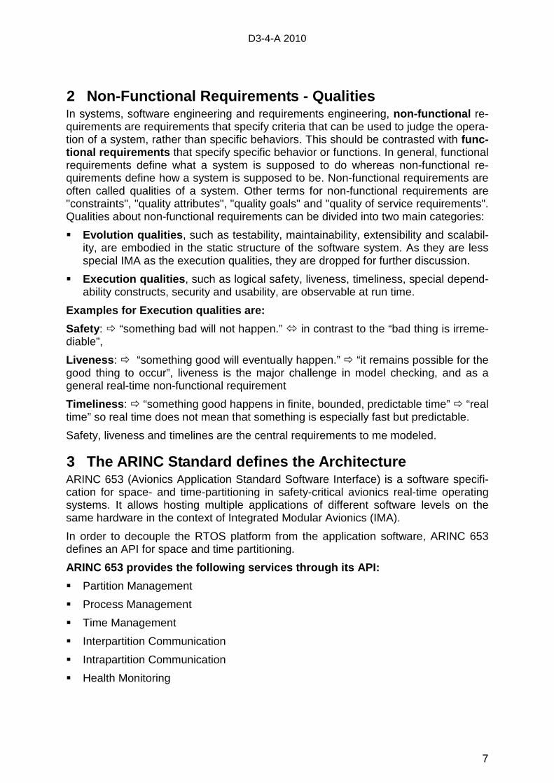
2 Non-Functional Requirements - Qualities In systems, software engineering and requirements engineering, non-functional re-quirements are requirements that specify criteria that can be used to judge the opera-tion of a system, rather than specific behaviors. This should be contrasted with func-tional requirements that specify specific behavior or functions. In general, functional requirements define what a system is supposed to do whereas non-functional re-quirements define how a system is supposed to be. Non-functional requirements are often called qualities of a system. Other terms for non-functional requirements are "constraints", "quality attributes", "quality goals" and "quality of service requirements". Qualities about non-functional requirements can be divided into two main categories:
� Evolution qualities , such as testability, maintainability, extensibility and scalabil-ity, are embodied in the static structure of the software system. As they are less special IMA as the execution qualities, they are dropped for further discussion.
� Execution qualities , such as logical safety, liveness, timeliness, special depend-ability constructs, security and usability, are observable at run time.
Examples for Execution qualities are:
Safety : � “something bad will not happen.” � in contrast to the “bad thing is irreme-diable”,
Liveness : � “something good will eventually happen.” � “it remains possible for the good thing to occur”, liveness is the major challenge in model checking, and as a general real-time non-functional requirement
Timeliness : � “something good happens in finite, bounded, predictable time” � “real time” so real time does not mean that something is especially fast but predictable.
Safety, liveness and timelines are the central requirements to me modeled.
3 The ARINC Standard defines the Architecture ARINC 653 (Avionics Application Standard Software Interface) is a software specifi-cation for space- and time-partitioning in safety-critical avionics real-time operating systems. It allows hosting multiple applications of different software levels on the same hardware in the context of Integrated Modular Avionics (IMA).
In order to decouple the RTOS platform from the application software, ARINC 653 defines an API for space and time partitioning.
ARINC 653 provides the following services through i ts API:
� Partition Management
� Process Management
� Time Management
� Interpartition Communication
� Intrapartition Communication
� Health Monitoring
D3-4-A 2010
8
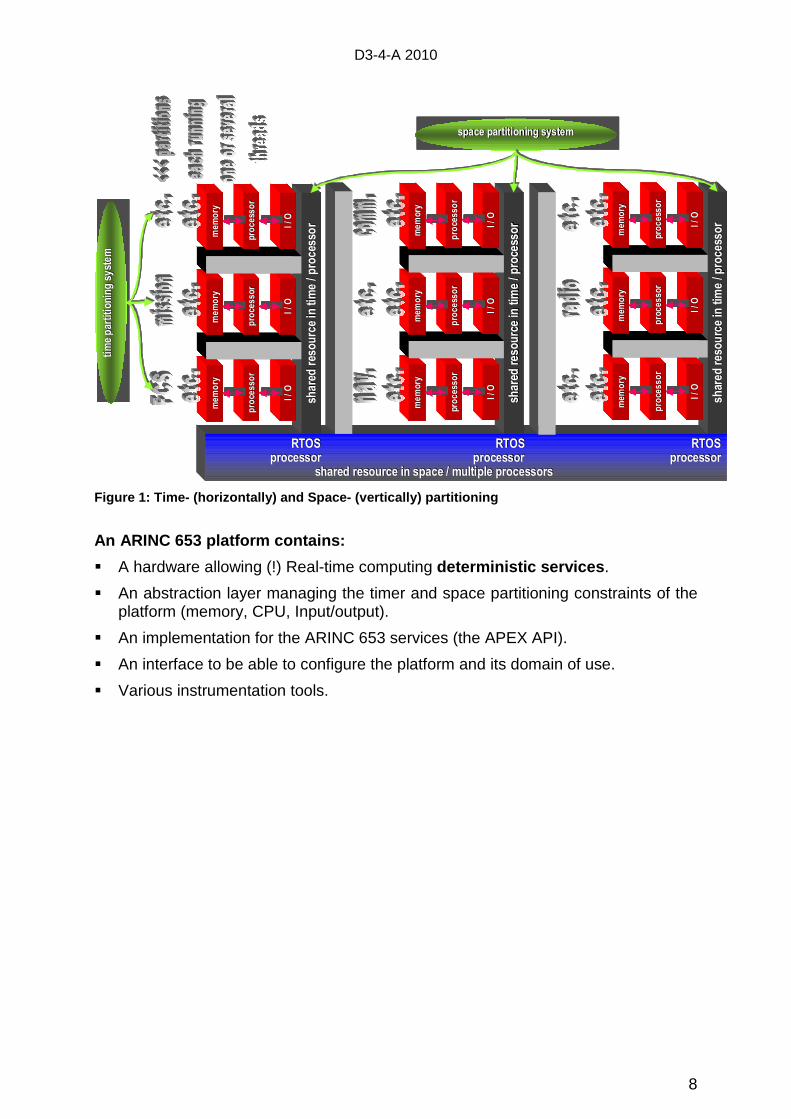
Figure 1: Time- (horizontally) and Space- (vertical ly) partitioning
An ARINC 653 platform contains:
� A hardware allowing (!) Real-time computing deterministic services .
� An abstraction layer managing the timer and space partitioning constraints of the platform (memory, CPU, Input/output).
� An implementation for the ARINC 653 services (the APEX API).
� An interface to be able to configure the platform and its domain of use.
� Various instrumentation tools.
RTOS RTOS RTOSRTOS RTOSRTOSprocessor processor processorprocessor processorprocessor
shared resource in space / mshared resource in space / multiple processorsultiple processors
shared resource in time / processor
shared resource in time / processor
I / O
I / O
processor
processor
memory
memory
I / O
I / O
processor
processor
memory
memory
I / O
I / O
processor
processor
memory
memory
shared resource in time / processor
shared resource in time / processor
I / O
I / O
processor
processor
memory
memory
I / O
I / O
processor
processor
memory
memory
I / O
I / O
processor
processor
memory
memory
shared resource in time / processor
shared resource in time / processor
I / O
I / O
processor
processor
memory
memory
I / O
I / O
processor
processor
memory
memory
I / O
I / O
processor
processor
memory
memory
time partitioning system
time partitioning system
time partitioning system
space partitioning systemspace partitioning systemspace partitioning system
RTOS RTOS RTOSRTOS RTOSRTOSprocessor processor processorprocessor processorprocessor
shared resource in space / mshared resource in space / multiple processorsultiple processors
shared resource in time / processor
shared resource in time / processor
I / O
I / O
processor
processor
memory
memory
I / O
I / O
processor
processor
memory
memory
I / O
I / O
processor
processor
memory
memory
shared resource in time / processor
shared resource in time / processor
I / O
I / O
processor
processor
memory
memory
I / O
I / O
processor
processor
memory
memory
I / O
I / O
processor
processor
memory
memory
I / O
I / O
processor
processor
memory
memory
I / O
I / O
processor
processor
memory
memory
I / O
I / O
processor
processor
memory
memory
shared resource in time / processor
shared resource in time / processor
I / O
I / O
processor
processor
memory
memory
I / O
I / O
processor
processor
memory
memory
I / O
I / O
processor
processor
memory
memory
shared resource in time / processor
shared resource in time / processor
I / O
I / O
processor
processor
memory
memory
I / O
I / O
processor
processor
memory
memory
I / O
I / O
processor
processor
memory
memory
I / O
I / O
processor
processor
memory
memory
I / O
I / O
processor
processor
memory
memory
I / O
I / O
processor
processor
memory
memory
shared resource in time / processor
shared resource in time / processor
I / O
I / O
processor
processor
memory
memory
I / O
I / O
processor
processor
memory
memory
I / O
I / O
processor
processor
memory
memory
shared resource in time / processor
shared resource in time / processor
I / O
I / O
processor
processor
memory
memory
I / O
I / O
processor
processor
memory
memory
I / O
I / O
processor
processor
memory
memory
I / O
I / O
processor
processor
memory
memory
I / O
I / O
processor
processor
memory
memory
I / O
I / O
processor
processor
memory
memory
time partitioning system
time partitioning system
time partitioning system
space partitioning systemspace partitioning systemspace partitioning system
D3-4-A 2010
9
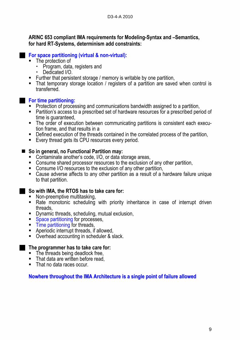
ARINC 653 compliant IMA requirements for Modeling-Syntax and –Semantics, for hard RT-Systems, determinism add constraints:
� For space partitioning (virtual & non-virtual): � The protection of
� Program, data, registers and � Dedicated I/O.
� Further that persistent storage / memory is writable by one partition, � That temporary storage location / registers of a partition are saved when control is
transferred.
� For time partitioning: � Protection of processing and communications bandwidth assigned to a partition, � Partition’s access to a prescribed set of hardware resources for a prescribed period of
time is guaranteed, � The order of execution between communicating partitions is consistent each execu-
tion frame, and that results in a � Defined execution of the threads contained in the correlated process of the partition, � Every thread gets its CPU resources every period.
� So in general, no Functional Partition may: � Contaminate another’s code, I/O, or data storage areas, � Consume shared processor resources to the exclusion of any other partition, � Consume I/O resources to the exclusion of any other partition, � Cause adverse affects to any other partition as a result of a hardware failure unique
to that partition.
� So with IMA, the RTOS has to take care for: � Non-preemptive multitasking, � Rate monotonic scheduling with priority inheritance in case of interrupt driven
threads, � Dynamic threads, scheduling, mutual exclusion, � Space partitioning for processes, � Time partitioning for threads, � Aperiodic interrupt threads, if allowed, � Overhead accounting in scheduler & slack.
� The programmer has to take care for: � The threads being deadlock free, � That data are written before read, � That no data races occur. NNoowwhheerree tthhrroouugghhoouutt tthhee IIMMAA AArrcchhiitteeccttuurree iiss aa ssiinnggllee ppooiinntt ooff ffaaiilluurree aalllloowweedd
D3-4-A 2010
10
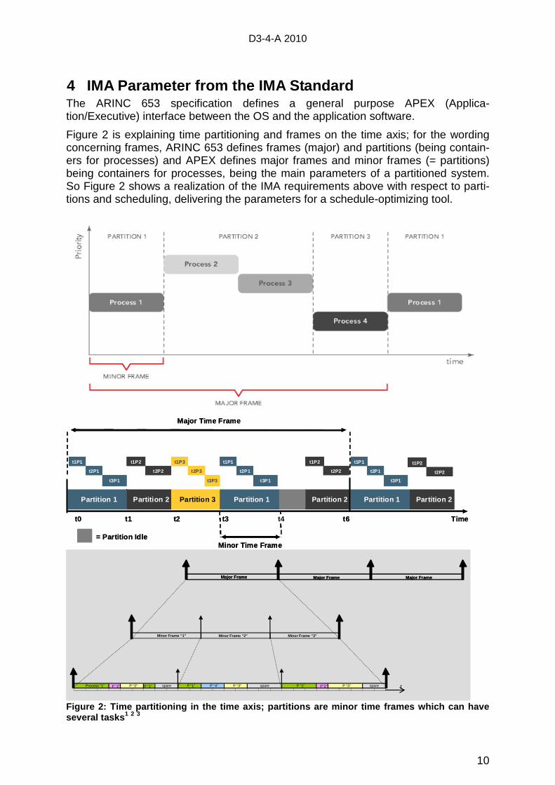
4 IMA Parameter from the IMA Standard The ARINC 653 specification defines a general purpose APEX (Applica-tion/Executive) interface between the OS and the application software.
Figure 2 is explaining time partitioning and frames on the time axis; for the wording concerning frames, ARINC 653 defines frames (major) and partitions (being contain-ers for processes) and APEX defines major frames and minor frames (= partitions) being containers for processes, being the main parameters of a partitioned system. So Figure 2 shows a realization of the IMA requirements above with respect to parti-tions and scheduling, delivering the parameters for a schedule-optimizing tool.
Major Time Frame
Partition 1 Partition 2 Partition 3 Partition 1 Partition 2 Partition 1 Partition 2
= Partition Idle
Timet1 t2 t3t0 t6
t1P1
t2P1
t3P1
t1P1
t2P1
t3P1
t1P1
t2P1
t3P1
t1P2
t2P2
t1P3
t2P3
t3P3
t1P2
t2P2
t1P2
t2P2
Minor Time Frame
t4
Major Time Frame
Partition 1 Partition 2 Partition 3 Partition 1 Partition 2 Partition 1 Partition 2
= Partition Idle
Timet1 t2 t3t0 t6
t1P1
t2P1
t3P1
t1P1
t2P1
t3P1
t1P1
t2P1
t3P1
t1P2
t2P2
t1P3
t2P3
t3P3
t1P2
t2P2
t1P2
t2P2
Minor Time Frame
t4
P “2” P “1” P”2”P “3” P “1”P “3”spare spareP “1” P “3”Process “1”
Minor Frame “1”
P “4” spare
Major Frame Major Frame Major Frame
Minor Frame “2” Minor Frame “3”
tP “2” P “1” P”2”P “3” P “1”P “3”spare spareP “1” P “3”Process “1”
Minor Frame “1”
P “4” spare
Major Frame Major Frame Major FrameMajor Frame Major Frame Major Frame
Minor Frame “2” Minor Frame “3”
t
Figure 2: Time partitioning in the time axis; parti tions are minor time frames which can have several tasks 1 2 3
D3-4-A 2010
11
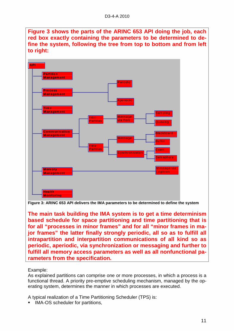
Figure 3 shows the parts of the ARINC 653 API doing the job, each red box exactly containing the parameters to be det ermined to de-fine the system, following the tree from top to bot tom and from left to right:
Sam pling
API
Sem aphore
Blackboard Buffer
Queuing
M em ory M an agem ent
Comm un icatio n M an agem ent
Pro cess M an agem ent
In ter-Parti tion
Tim e M an agem ent
Partitio n M an agem ent
In tra- Parti tion
P eriodic
A periodic
M essage via Port
M essage
S ynchronisation Event
Health M onitor ing
M essage via Logbook
Figure 3: ARINC 653 API delivers the IMA parameters to be determined to define the system The main task building the IMA system is to get a t ime determinism based schedule for space partitioning and time part itioning that is for all “processes in minor frames” and for all “mi nor frames in ma-jor frames” the latter finally strongly periodic, a ll so as to fulfill all intrapartition and interpartition communications of all kind so as periodic, aperiodic, via synchronization or messagi ng and further to fulfill all memory access parameters as well as all nonfunctional pa-rameters from the specification. Example: As explained partitions can comprise one or more processes, in which a process is a functional thread. A priority pre-emptive scheduling mechanism, managed by the op-erating system, determines the manner in which processes are executed. A typical realization of a Time Partitioning Scheduler (TPS) is: � IMA-OS scheduler for partitions,
D3-4-A 2010
12
� Intra-partition scheduling use priority pre-emptive scheduling e.g. see APEX, POSIX, etc.
It must be possible to model this architectures and behavior from ARINC 653 API parameters.
From above this implies that processes can have different performance require-ments, which split into two categories: Rate requirements and response requirements: � Rate requirement where a task must provide service at a particular rate (so pe-
riodic in Figure 3). � Response requirement when an event occurs, the task responds to it within a
certain amount of time (so a periodic in Figure 3). That is partition internal business, so the partition is responsible for its internal pro-cess behavior. Neither the process nor its attributes are visible outside of the parti-tion.
5 What is Synthesis, what must be modeled? It is mentioned here that for hard real-time systems determinism is the major parame-ter and derived from section 2 “Non-Functional Requirements - Qualities”. That is not, that determinism follows directly from non-functional requirements, but the other way around: For deterministic systems it’s easier to show to fulfill non-functional requirements, e.g. timely constraints. In principle any system, synchro-nous, asynchronous, allowing interrupts, etc. could fulfill given non-functional re-quirements, but showing and so validating that normally is far beyond a complexity being mastered by man using any tools. Note: A system is deterministic or not, there is no between. When determinism is vio-lated at any point, the system is not deterministic. In practice a system is determinis-tic, when it’s proven to be deterministic, otherwise it is not. A system-wide perspective is necessary when designing the IMA solution in order to ensure robust time and space partitioning is preserved during normal operation. Time and space partitioning must be deterministic in an ARINC 653 based IMA sys-tem in order to avoid aircraft certification concerns and incapability with the standards and guidelines in DO-178B. Methods for identifying, analyzing, and rectifying deter-minism in IMA systems are to be used. How does synthesis follow the parameters? What are the major issues? Several IMA system design challenges are interrupts, direct memory access (DMA), system I/O, as they can produce unpredictable distortions that violate the constraints of time and space partitioning, best protected by determinism as a sufficient condi-tion4. � DMA: In comparing standard memory transactions with DMA transactions, it
should be evident that the transaction efficiency provided by DMA engines pro-vides a powerful means of transferring large blocks of memory within the system; however, the power afforded by the DMA engine is not without potential ramifica-tions to robust partitioning. Since the DMA engine is granted exclusive access to the memory bus to perform a block transfer, and since the memory bus is a re-
D3-4-A 2010
13
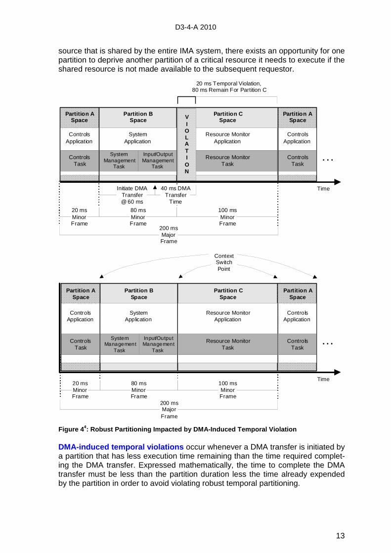
source that is shared by the entire IMA system, there exists an opportunity for one partition to deprive another partition of a critical resource it needs to execute if the shared resource is not made available to the subsequent requestor.
DMA-induced temporal violations occur whenever a DMA transfer is initiated by a partition that has less execution time remaining than the time required complet-ing the DMA transfer. Expressed mathematically, the time to complete the DMA transfer must be less than the partition duration less the time already expended by the partition in order to avoid violating robust temporal partitioning.
Partition ASpace
Partition BSpace
Partition CSpace
20 msMinorFrame
200 msMajorFrame
Time
. . .
Partition ASpace
ControlsApplication
ControlsTask
SystemApplication
System Management
Task
Input/OutputManagement
Task
Resource MonitorApplication
Resource MonitorTask
ControlsApplication
ControlsTask
80 msMinorFrame
100 msMinorFrame
Initiate DMATransfer @ 60 ms
40 ms DMATransfer
Time
VIOLATION
20 ms Temporal Violation, 80 ms Remain For Partition C
Partition ASpace
Partition BSpace
Partition CSpace
20 msMinorFrame
200 msMajorFrame
Time
ContextSwitchPoint
. . .
Partit ion ASpace
ControlsApplication
ControlsTask
SystemApplication
System Management
Task
Input/OutputManagement
Task
Resource MonitorApplication
Resource MonitorTask
ControlsApplication
ControlsTask
80 msMinorFrame
100 msMinorFrame
Figure 44: Robust Partitionin g Impacted b y DMA-Induced Temporal Violation
D3-4-A 2010
14
� Interrupts : In general, a processor interrupt is caused by an external signal which triggers an asynchronous event in the system where normal operation is sus-pended, and processing is redirected to a piece of software that handles or ser-vices the interrupt event. When a processor interrupt is enabled and the interrupt event occurs, the processor must switch contexts to a space defined by the inter-rupt vector and a time specified by the execution duration of the interrupt handler software routine. But in highly critical IMA following ARINC 653 the only interrupt typically found in a robustly-partitioned system is the system clock, and this is for good reason. The RTOS in the IMA system must be in complete control of temporal and spatial contexts in order to guarantee robust partitioning, and interrupts present the threat of injecting an unpredictable, independent context into the system that redirects normal operation, destroying determinism. While interrupts may provide a conven-ient method of forcing the system to handle some high-priority external event, handling interrupts in the IMA system may cause distortions in the temporal do-main that enervate robust partitioning. In case of interrupts when context is restored, the time spent handling the inter-rupt is accounted for by the interrupted partition, since any readjustment of the partition’s original execution timeline may introduce an unacceptable amount of jit-ter into the system and violate the strict scheduling requirements given in ARINC 653. Thus as a consequence of strict scheduling, if the global interrupt handler’s duration exceeds the execution time remaining in the interrupted partition, execu-tion time will be accounted for by the subsequent partition(s). Interrupt-induced temporal violations occur whenever an interrupt other than the system clock interrupt occurs during the normal execution schedule of the system. Interrupts could be caused by external events such as I/O operations transpiring or perhaps might even be caused by activity directly initiated by the partition application. Externally-caused interrupt activity might not be forbidden in principle but is especially problematic for the IMA system since there may be no method to completely analyze or characterize the ac tivity unless it is period-ic in nature and even more being deterministic . In general, ARINC 653 partitioned operating systems tend to avoid use of inter-rupts aside from the system clock. Systems that do employ interrupts typically use a combination of all of the aforementioned techniques in order to achieve a level of determinism consistent with the criticality level they will be certified for.
� I/O: I/O in a partitioned IMA system presents the developer with one of their most challenging aspects of design. While ARINC 653 clearly defines operations and interfaces for inter-partition I/O via ARINC sampling or queuing ports, I/O to phys-ical devices or inter-module I/O are left to RTOS implementers and other stake-holders to provide. As discussed previously, use of interrupts can caus e temporal violations in the IMA system due to their asynchronous nature. The removal of asynchronous behavior from the syste m tends to drive I/O solutions towards either polling-mode software oper ations or towards a hardware-based design. The polling–mode solution clearly introduces a limit to the bandwidth of the I/O data that may be processed and also increases the la-tency of response; therefore, the solution must be analyzed for acceptable per-formance. Ideally, the architecture of the I/O solution would try to isolate any I/O access to a single partition-based I/O implementation in order to afford the maxi-mum benefit of partitioning. Such I/O architecture defines the “classical” I/O parti-tion model that is usually the first choice of designers when confronted with a par-titioned system. The primary limitation of the classical I/O partition solution is that
D3-4-A 2010
15
the I/O bandwidth will be limited by the frequency at which the I/O partition is scheduled in the major frame. Depending on the data rate required, the classical I/O partition model may not be acceptable since the necessary periodicity of the I/O partition may be too high to be accommodated by the overall system sched-ule. I/O-induced temporal violations can occur for a number of reasons as previous-ly discussed, and in general, such violations are typically remedied either by avoiding potentially temporally unsafe operations or by designing sufficient intelli-gence into the drivers to prevent them from occurring. E.g. from a performance standpoint, it is desirable to transfer data to driver memory space (buffer) and al-low the application to continue operating, with the expectation of a process sub-sequently transferring the data from driver memory space to the device.
5.1 Strongly Cyclic Major Time Frames � Major time frames are scheduled strongly cyclic (round robin) and deterministic.
5.2 Minor Time Frames - Partition Management: � Partitions can be of different criticality (e.g. with respect to ARINC 653). They are
executed cyclically in a strict order. This order is also called partition time frame, which is configured at the system configuration time and repeated cyclically. Eve-ry partition is assigned a fixed duration, i.e. allowed execution time, and period, i.e. a time point of partition activation within a frame/cycle.
� By cyclic scheduling of partitions, if a partition does a restart, it will restart from the last saved position. When the partition is in context, the processes will contin-ue where they last left off. The scheduler does not restart scheduling processes with respect to partition-internal processes each time the partition is in context. This enables continuation of the application within real-time.
5.3 Processes in partitions: � That is what is possible in principle, but following ARINC 653 for highly critical
systems, determinism is to be followed also inside the partitions and polling is to substitute interrupts so also avoiding aperiodic processes.
� Each partition comprises one or more tasks/processes that combine dynamically to provide the functions associated with that partition. According to the character-istics associated with the partition, the constituent processes may operate concur-rently in order to achieve their functional and real-time requirements. Multiple pro-cesses are therefore supported within the partition.
� Processes are designed for either periodic or non-periodic execution. There shall be a mechanism that either starts a process again in case of an error, or termi-nates it or schedules it again. Partition or Process code may run only in user mode (of an underlying CPU). Therefore no privileged instructions can be execut-ed.
� Each process has a priority level. If a partition is active, the process of the highest priority within the partition is selected and executed. When a partition is resched-uled, the sequence of processes is started in a state as it was saved as the pro-cesses have been pre-empted as the partition was replaced by another cyclically. Ruling all processes having finished execution at any one time inside each parti-tion and so before cyclic replacement of the partition is a simplified, prevalent and comprehensive variant.
� Periodic processes : they have a constant time interval between successive requests.
D3-4-A 2010
16
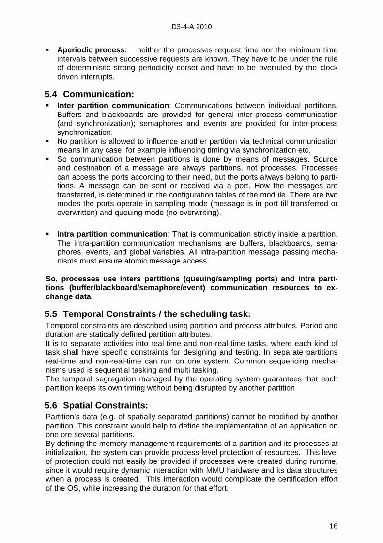
� Aperiodic process : neither the processes request time nor the minimum time intervals between successive requests are known. They have to be under the rule of deterministic strong periodicity corset and have to be overruled by the clock driven interrupts.
5.4 Communication: � Inter partition communication : Communications between individual partitions.
Buffers and blackboards are provided for general inter-process communication (and synchronization); semaphores and events are provided for inter-process synchronization.
� No partition is allowed to influence another partition via technical communication means in any case, for example influencing timing via synchronization etc.
� So communication between partitions is done by means of messages. Source and destination of a message are always partitions, not processes. Processes can access the ports according to their need, but the ports always belong to parti-tions. A message can be sent or received via a port. How the messages are transferred, is determined in the configuration tables of the module. There are two modes the ports operate in sampling mode (message is in port till transferred or overwritten) and queuing mode (no overwriting).
� Intra partition communication : That is communication strictly inside a partition. The intra-partition communication mechanisms are buffers, blackboards, sema-phores, events, and global variables. All intra-partition message passing mecha-nisms must ensure atomic message access.
So, processes use inters partitions (queuing/sampli ng ports) and intra parti-tions (buffer/blackboard/semaphore/event) communica tion resources to ex-change data.
5.5 Temporal Constraints / the scheduling task: Temporal constraints are described using partition and process attributes. Period and duration are statically defined partition attributes. It is to separate activities into real-time and non-real-time tasks, where each kind of task shall have specific constraints for designing and testing. In separate partitions real-time and non-real-time can run on one system. Common sequencing mecha-nisms used is sequential tasking and multi tasking. The temporal segregation managed by the operating system guarantees that each partition keeps its own timing without being disrupted by another partition
5.6 Spatial Constraints: Partition’s data (e.g. of spatially separated partitions) cannot be modified by another partition. This constraint would help to define the implementation of an application on one ore several partitions. By defining the memory management requirements of a partition and its processes at initialization, the system can provide process-level protection of resources. This level of protection could not easily be provided if processes were created during runtime, since it would require dynamic interaction with MMU hardware and its data structures when a process is created. This interaction would complicate the certification effort of the OS, while increasing the duration for that effort.
D3-4-A 2010
17
6 ANNEX
6.1 Modeling and Model Driven Engineering 5 Model Driven Engineering (MDE) aims to raise the level of abstraction in program specification and increase automation in program development. The idea promoted by MDE is to use models at different levels of abstraction for developing systems, thereby raising the level of abstraction in program specification. An increase of auto-mation in program development is reached by using executable model transfor-mations. Higher-level models are transformed into lower level models until the model can be made executable using either code generation or model interpretation.
A model is specified in some model notation or model language. Since model lan-guages are mostly tailored to a certain domain, such a language is often called a Domain-Specific Language (DSL). A model specified using a DSL is called a Do-main-Specific Model (DSM). A DSL can be visual or textual. A sound language de-scription contains an abstract syntax, one or more concrete syntax descriptions, mappings between abstract and concrete syntax, and a description of the semantics. The abstract syntax of a language is often defined using a meta-model.
As in each software engineering approach quality is an important aspect of MDE. Quality in MDE can be checked, or ensured, with three different techniques: model validation, model checking, and model-based testing.
MDE is often confused with Model Driven Architecture (MDA). MDA can be seen as OMG's (Object Management Group) vision on MDE. The MDA focuses on the tech-nical variability in software, i.e. how to specify software in a platform independent manner. Another term in this field trademarked by the OMG is Model Driven Devel-opment (MDD).
6.2 The MARTE 6 Profile as an Architecture Modeling Possibility MARTE (Modeling and Analysis Real-Time and Embedded) is an OMG standard.
The advent of Unified Modeling Language version 2.0 (UML 2.0), promises to be a major breakthrough in the field of formal description techniques. The built-in extensi-bility mechanism of UML 2.0 which facilitates extending UML 2.0 through profiles makes UML 2.0 an important candidate for modeling real-time protocols.
The MARTE specification of a UML profile adds capabilities to UML for model-driven development of Real Time and Embedded Systems (RTES). This extension, called the UML profile for MARTE provides support for specification, design, and verifica-tion/validation stages. This new profile is intended to replace the existing UML SPT Profile for Schedulability, Performance and Time.
The profile adds concepts for time and resources.
An important contribution of MARTE lies in its time model, centered on the notion of multiform time (logical or chronometric), that enriches UML with explicit time model elements (clocks, clocks type …). This is a real advance in regard to the SPT (Scheduling Performance and Time) profile which considers time as an implicit notion closed to the physical time, modeled by a simple annotation onto UML models. Scheduling analyses are based on well founded theory widely used in the domain of real-time control systems.
Applying such analysis techniques to a UML design requires extracting from func-tional and non-functional models the temporal characteristics of every function of
D3-4-A 2010
18
these models. The main characteristics are the period, the deadline possibly equal to the period. Analysis techniques need also, as input, the Worst Case Execution Time of the function (WCET).
In addition, MARTE provides two other models for describing execution platforms, and the allocation of application functions onto the resources of the platform.
So MARTE can be used for building four models:
� One for representing the functional part of the system mainly composed of ac-tivity diagrams, state machine and structure diagrams.
� Another model called the time model contains the main time entities (clocks, clock type, clock constraints) as units for expressing the non-functional temporal characteristics (period) and constraints (deadline). This is related to determinism but it is not clear if MARTE can be used to guaranty determinism of a system.
� One further model represents the resources and finally
� Another model represents the allocation of the functional parts onto these resources . The allocation model allows in particular, an identification of the tasks of the system by exploiting, in addition to non-functional temporal characteris-tics , other temporal characteristics such as the WCET which actually is hardware dependent.
Diverse CASE tools provide the possibility to automatically generate code out of the models. For UML tools code can only be generated from class- and state-diagrams, which only can be done for object oriented languages like C++ and Java. So code generation can be done for real-time embedded systems using these languages; for highly depended systems as flight control systems in aeronautics needing level A certification (counts also for level B applications) we have the known UML problem of code generation from an modeling tool for object oriented languages.
See also page 25: MARTE and code generation.
A further problem of code generation is the lacking information in the models needed to generate at least a reasonable amount of code, at least some class structure skel-eton. UML profiles as MARTE, SysML and xUML are extending the UML semantic and so solve that problem.
The MARTE Modeling: MARTE Foundation package 7 This package defines all the basic foundational concepts required for design and analysis of real-time and embedded system. It provides model developers with con-structs for modeling the following:
� Non-functional Properties (NFPs): This sub-package offers means for specify-ing the non-functional properties of the real-time system like memory usage, pow-er consumption, etc. It also explains how these NFPs can be attached to the model elements. In short, this sub-profile specifies a general framework for anno-tating UML model elements with NFPs.
� Time Modeling: This package enables time and time-related structure modeling. The main objective of MARTE is to provide basic and advanced time modeling concepts. As a profile succeeding the UML SPT profile, MARTE has to support a
D3-4-A 2010
19
metric time with implicit reference to physical time. However, MARTE supports general time models like ‘physical’, ‘logical’ and multiform. These advanced time related concepts could then be used to develop various Models of Computation and Communication (MoCC).
� Generic Resource Modeling (GRM): This Sub-package provides all the neces-sary stereotypes and tagged values to represent resources like communication media, computing resources, storage resources etc. Further, it includes features that are needed for dealing with modeling of executing platforms with different levels of abstraction and modeling of both ‘hardware’ (e.g. physical communica-tion channels) and ‘software’ (e.g., real-time operating systems) platforms. The GRM package along with Time modeling package can be used for specifying tim-ing constraints and when used with the NFP package can be used for specifying the quality of services.
� Generic Component Model (GCM): This package is useful for applying compo-nent base strategies in the domain of real-time and embedded systems. GCM package is nothing but refinements applied to the structured classes of UML on top of which a support SysML blocks has been added. Thus this model provides a common denominator for various models of computation and communication (MoCCs). This package serves to provide a model as general as possible, that is independent of a specific execution semantics, upon which real-time characteris-tics can be applied at a later point in time.
� Allocation Modeling: The MARTE profile allows designers to model both appli-cations and execution platforms. An application element in MARTE could be a service, a computation or a real-time operating system (RTOS) function. An exe-cution platform is a set of connected resources representing the hardware archi-tecture. It consists of <<HW_ Resource>> such as storage resource (RAM, ROM or Cache), communication devices (Bus and I/O devices) and computing resource (processor, hardware accelerator) etc. After modeling the application and hard-ware architecture it is important to map the application tasks onto the execution platform in real-time embedded applications. Mapping places an important role when it comes to performance. MARTE provides a mechanism called ‘allocation’ which allows designers to specify mapping. A MARTE allocation is an association between a MARTE application and a MARTE execution platform. The main con-cept of allocation is <<Allocate>>, it is used for associating elements from a logi-cal context, application model elements, to named elements described in a more physical context, execution platform model elements. The concepts defined using this foundation package are then refined in the following two packages to support modeling and analysis concerns of the real-time system.
MARTE Design Model This package addresses model-based design starting from requirement capture to specification, design and implementation. It provides high level concepts for modeling both, quantitative and qualitative features of real-time systems/protocols. Further, it also provides means for detailed description of software and hardware resources used for execution of an application.
� RTE Model of Computation and Communication (RTEMoCC ): The main ob-jective of this package is to provide high-level modeling concepts, that enable modeling quantitative features like deadline and period, and qualitative features that are related to behavior, like communication and concurrency.
D3-4-A 2010
20
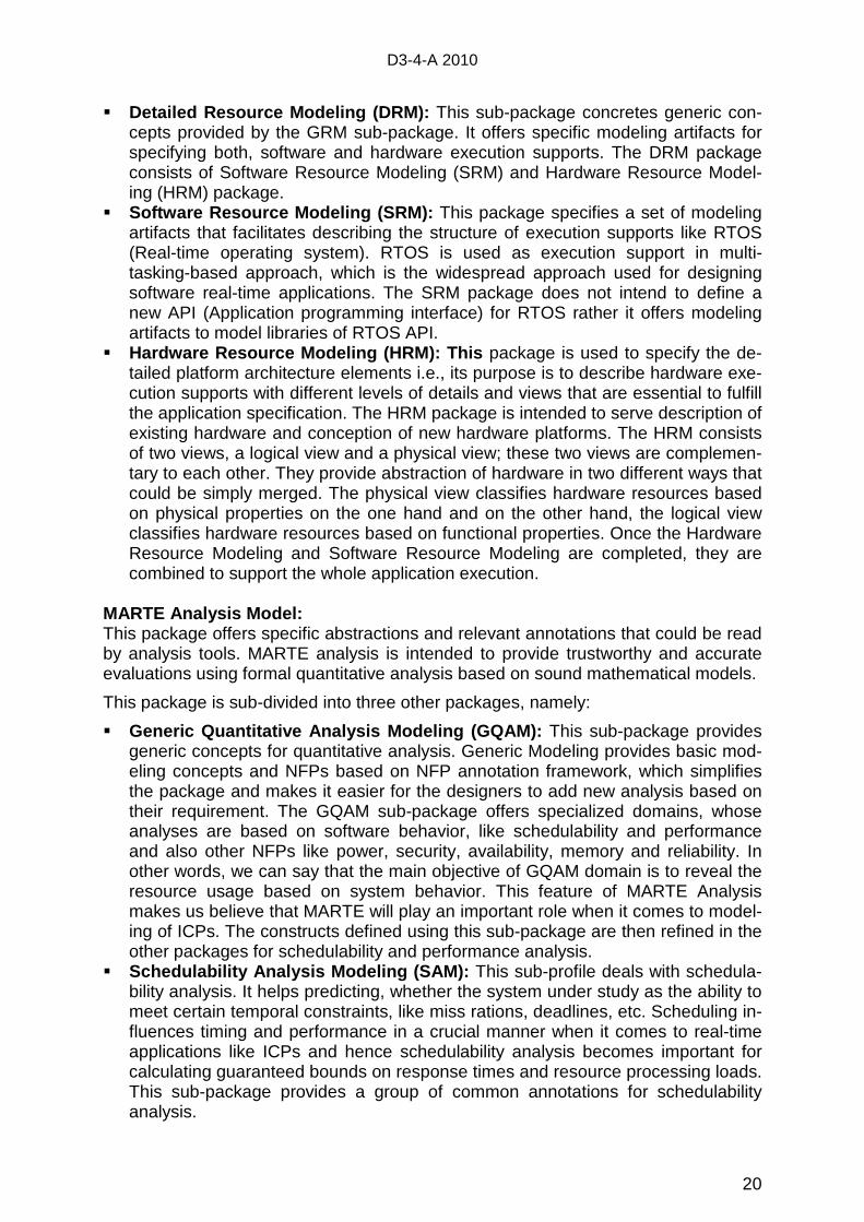
� Detailed Resource Modeling (DRM): This sub-package concretes generic con-cepts provided by the GRM sub-package. It offers specific modeling artifacts for specifying both, software and hardware execution supports. The DRM package consists of Software Resource Modeling (SRM) and Hardware Resource Model-ing (HRM) package.
� Software Resource Modeling (SRM): This package specifies a set of modeling artifacts that facilitates describing the structure of execution supports like RTOS (Real-time operating system). RTOS is used as execution support in multi-tasking-based approach, which is the widespread approach used for designing software real-time applications. The SRM package does not intend to define a new API (Application programming interface) for RTOS rather it offers modeling artifacts to model libraries of RTOS API.
� Hardware Resource Modeling (HRM): This package is used to specify the de-tailed platform architecture elements i.e., its purpose is to describe hardware exe-cution supports with different levels of details and views that are essential to fulfill the application specification. The HRM package is intended to serve description of existing hardware and conception of new hardware platforms. The HRM consists of two views, a logical view and a physical view; these two views are complemen-tary to each other. They provide abstraction of hardware in two different ways that could be simply merged. The physical view classifies hardware resources based on physical properties on the one hand and on the other hand, the logical view classifies hardware resources based on functional properties. Once the Hardware Resource Modeling and Software Resource Modeling are completed, they are combined to support the whole application execution.
MARTE Analysis Model: This package offers specific abstractions and relevant annotations that could be read by analysis tools. MARTE analysis is intended to provide trustworthy and accurate evaluations using formal quantitative analysis based on sound mathematical models.
This package is sub-divided into three other packages, namely:
� Generic Quantitative Analysis Modeling (GQAM): This sub-package provides generic concepts for quantitative analysis. Generic Modeling provides basic mod-eling concepts and NFPs based on NFP annotation framework, which simplifies the package and makes it easier for the designers to add new analysis based on their requirement. The GQAM sub-package offers specialized domains, whose analyses are based on software behavior, like schedulability and performance and also other NFPs like power, security, availability, memory and reliability. In other words, we can say that the main objective of GQAM domain is to reveal the resource usage based on system behavior. This feature of MARTE Analysis makes us believe that MARTE will play an important role when it comes to model-ing of ICPs. The constructs defined using this sub-package are then refined in the other packages for schedulability and performance analysis.
� Schedulability Analysis Modeling (SAM): This sub-profile deals with schedula-bility analysis. It helps predicting, whether the system under study as the ability to meet certain temporal constraints, like miss rations, deadlines, etc. Scheduling in-fluences timing and performance in a crucial manner when it comes to real-time applications like ICPs and hence schedulability analysis becomes important for calculating guaranteed bounds on response times and resource processing loads. This sub-package provides a group of common annotations for schedulability analysis.
D3-4-A 2010
21
� Performance Analysis Modeling (PAM): The sub-package offers support for performance analysis, i.e. it provides ways to determine whether a system can provide adequate performance under non-deterministic behavioral conditions, based on statistical values. The PAM package includes both, ‘single-case’ analy-sis, for a particular set of given input parameter and also ‘multi-case’ analysis, for e.g. ‘sensitivity analysis’ which helps in identifying risky workload situations, ideal operational parameter, etc. and ‘capacity analysis’ which identifies the design or configuration capabilities.
So in short: MARTE relation to OMG standards: � UML superstructure model � OCL 2 for domain constraints MARTE relation to RTE OMG standards: � UML profile for QoS and FT mechanisms � UML profile for SoC � RT CORBA profile � UML profile for SE (SysML) MARTE does: � Any time aspect refers to a clock � Time is not limited to physical time � Clock uncertainties � Design to runtime clocks � Supports synchronism So: MARTE is a language for non-functional properti es � Based on UML structured classes, based on that is support of SysML � Supports control flow and data flow (that is an orthogonal picture to a UML class-
and object structure) The MARTE profile, which replaces the current profile for Schedulability, Perfor-mance, and Time, is one of a group of related OMG specifications (Figure 6.1). The most obvious of these is the UML 2 Superstructure specification, which is the basis for any UML profile. It also uses the OCL 2.0 specification for all constraints specified in OCL.
D3-4-A 2010
22
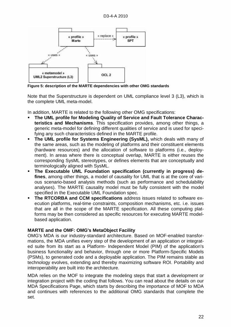
Figure 5: description of the MARTE dependencies wit h other OMG standards Note that the Superstructure is dependent on UML compliance level 3 (L3), which is the complete UML meta-model. In addition, MARTE is related to the following other OMG specifications: � The UML profile for Modeling Quality of Service and Fault Tolerance Charac-
teristics and Mechanisms . This specification provides, among other things, a generic meta-model for defining different qualities of service and is used for speci-fying any such characteristics defined in the MARTE profile.
� The UML profile for Systems Engineering (SysML), which deals with many of the same areas, such as the modeling of platforms and their constituent elements (hardware resources) and the allocation of software to platforms (i.e., deploy-ment). In areas where there is conceptual overlap, MARTE is either reuses the corresponding SysML stereotypes, or defines elements that are conceptually and terminologically aligned with SysML.
� The Executable UML Foundation specification (curren tly in progress) de-fines , among other things, a model of causality for UML that is at the core of vari-ous scenario-based analysis methods (such as performance and schedulability analyses). The MARTE causality model must be fully consistent with the model specified in the Executable UML Foundation spec.
� The RTCORBA and CCM specifications address issues related to software ex-ecution platforms, real-time constraints, composition mechanisms, etc. i.e. issues that are all in the scope of the MARTE specification. All these computing plat-forms may be then considered as specific resources for executing MARTE model-based application.
MARTE and the OMF: OMG's MetaObject Facility OMG's MDA is our industry-standard architecture. Based on MOF-enabled transfor-mations, the MDA unifies every step of the development of an application or integrat-ed suite from its start as a Platform- Independent Model (PIM) of the application's business functionality and behavior, through one or more Platform-Specific Models (PSMs), to generated code and a deployable application. The PIM remains stable as technology evolves, extending and thereby maximizing software ROI. Portability and interoperability are built into the architecture.
MDA relies on the MOF to integrate the modeling steps that start a development or integration project with the coding that follows. You can read about the details on our MDA Specifications Page, which starts by describing the importance of MOF to MDA and continues with references to the additional OMG standards that complete the set.
D3-4-A 2010
23
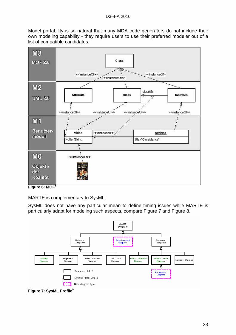
Model portability is so natural that many MDA code generators do not include their own modeling capability - they require users to use their preferred modeler out of a list of compatible candidates.
Figure 6: MOF 8 MARTE is complementary to SysML:
SysML does not have any particular mean to define timing issues while MARTE is particularly adapt for modeling such aspects, compare Figure 7 and Figure 8.
Figure 7: SysML Profile 9
D3-4-A 2010
24
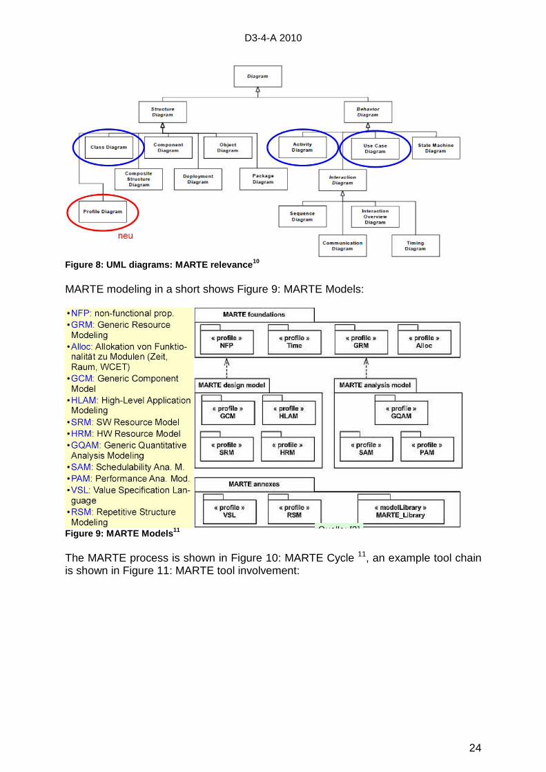
Figure 8: UML diagrams: MARTE relevance 10 MARTE modeling in a short shows Figure 9: MARTE Models:
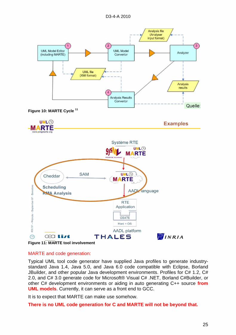
Figure 9: MARTE Models 11 The MARTE process is shown in Figure 10: MARTE Cycle 11, an example tool chain is shown in Figure 11: MARTE tool involvement:
D3-4-A 2010
25
Figure 10: MARTE Cycle 11
Figure 11: MARTE tool involvement MARTE and code generation:
Typical UML tool code generator have supplied Java profiles to generate industry-standard Java 1.4, Java 5.0, and Java 6.0 code compatible with Eclipse, Borland JBuilder, and other popular Java development environments. Profiles for C# 1.2, C# 2.0, and C# 3.0 generate code for Microsoft® Visual C# .NET, Borland C#Builder, or other C# development environments or aiding in auto generating C++ source from UML models . Currently, it can serve as a front end to GCC.
It is to expect that MARTE can make use somehow.
There is no UML code generation for C and MARTE wil l not be beyond that.
D3-4-A 2010
26
6.3 The DMOSES12 Profile as an Architecture Modeling Possibility The DMOSES-profile modeling method has the focus of determinism, independent from the platform. This could make it superior over MARTE regarding hart real-time systems.
It’s based on the modeling and Implementation of deterministic, signal processing, embedded systems. So the DMOSES modeling guaranties determinism from the models to the code. For that the DMOSES profile guaranties unambiguous UML models for code generation.
The MARTE profile is for modeling real-time embedded systems, and so adds con-cepts for time and resources, multiple types for time can be modeled. Further UML diagrams are extended for describing HW-platforms in successive detail. Stereotypes for modeling scheduling are added to analyze schedules and determine the perfor-mance of a system, so time plays the major role in MARTE.
In contrast, DMOSES aims in determinism. It does not modeling of a schedule explic-itly, but that is an inherent input based of static priorities.
So the DMOSES profile has different objectives as both, MARTE and SysML.
Deterministic models:
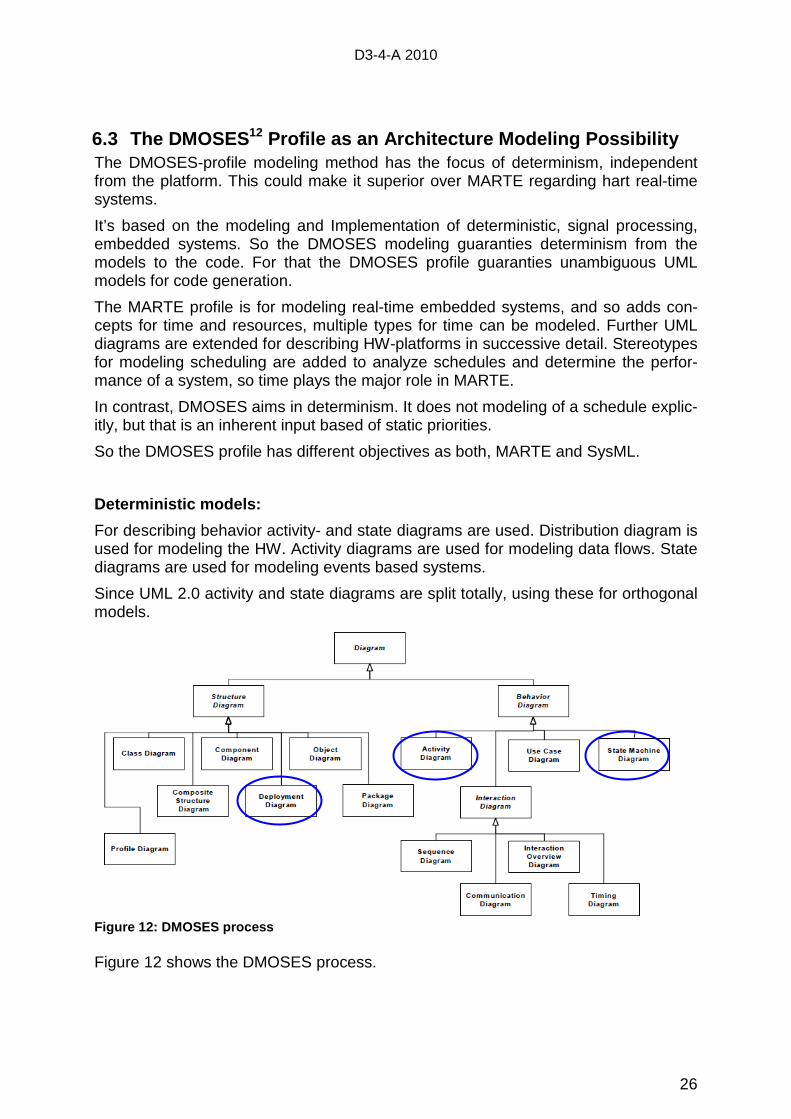
For describing behavior activity- and state diagrams are used. Distribution diagram is used for modeling the HW. Activity diagrams are used for modeling data flows. State diagrams are used for modeling events based systems.
Since UML 2.0 activity and state diagrams are split totally, using these for orthogonal models.
Figure 12: DMOSES process Figure 12 shows the DMOSES process.
D3-4-A 2010
27
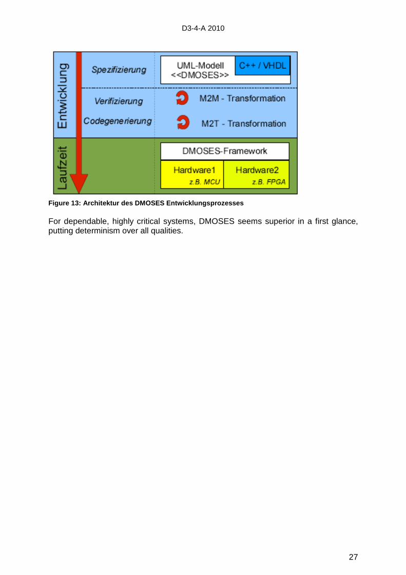
Figure 13: Architektur des DMOSES Entwicklungsproze sses For dependable, highly critical systems, DMOSES seems superior in a first glance, putting determinism over all qualities.
D3-4-A 2010
28
Index 1 http://yunus.hacettepe.edu.tr/~ki/dersler/bbs671/Sunu%20Onerileri%20ve%20Projeler/safety-critical-
sw-dev_wp.pdf 2 vxworks_653_programmers_guide_2.1 3 Präsentation Joachim Hampp, VxWorks MILS, Wind River 4 Justin Littlefield-Lawwill, GE Aviation, Grand Rapids, Michigan, Larry Kinnan, Wind River Systems,
Alameda, California: SYSTEM CONSIDERATIONS FOR ROBUST TIME AND SPACE PARTITIONING IN INTEGRATED MODULAR AVIONICS
5 Johan den Haan / http://www.theenterprisearchitect.eu 6 OMG Document Number: ptc/2008-06-09 - A UML Profile for MARTE: Modeling and Analysis of Re-
al-Time Embedded systems, Beta 2 7 http://www.jot.fm/issues/issue_2010_03/article5.pdf 8 http://upload.wikimedia.org/wikipedia/commons/9/93/M0-m3.png 9 Marcello Mura, Amrit Pand, Mauro Prevostini - ALaRI - University of Lugano
http://www2.lifl.fr/MARTEworkshop/presentations/Presentation.pdf 10 Dirk Müller: Entwurf von SW für eingeb. Systeme, WS 2009/10 – TU Chemnitz 11 S. Gérard, F. Terrier, B. Selic, P. Boulet: “MARTE, The UML standard extension for real-time and
embedded systems“, 2008, http://www-users.cs.york.ac.uk/~burns/papers/MARTE.pdf 12 Zamira Daw, Flor Alvarez, Marcus Vetter - Institut für Embedded Systems, Hochschule Mannheim -
Methode zur Entwicklung sicherheitskritischer eingebetteter Systeme mittels deterministischer UML-Modelle
Beitrag zu ZP-AP 3
D3.4.A – Version 1.0
Zuarbeiten zu den ThemenkomplexenSystemspezifikation, Verifikation,Timing-Modelle, Reconfiguration
EADS IW
Dr. Stephan C. Stilkerich
Inhalt
• Anforderungen und Strategien zur System-Spezifikation
• Anforderungen bzgl. Verifikation und Abgleichmit Avionic Standards
• Anforderungen für die Bestimmung des Timingsin Avionic Systemen; insb. ARINC653
• Anforderungen für Rekonfiguration
2
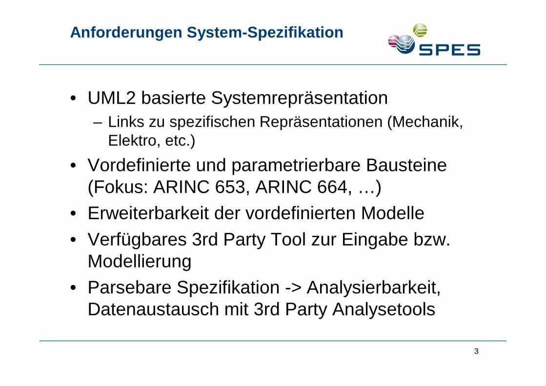
Anforderungen System-Spezifikation
• UML2 basierte Systemrepräsentation
– Links zu spezifischen Repräsentationen (Mechanik,Elektro, etc.)
• Vordefinierte und parametrierbare Bausteine(Fokus: ARINC 653, ARINC 664, …)
• Erweiterbarkeit der vordefinierten Modelle
• Verfügbares 3rd Party Tool zur Eingabe bzw.Modellierung
• Parsebare Spezifikation -> Analysierbarkeit,Datenaustausch mit 3rd Party Analysetools
3
Anforderungen System-Spezifikation
• Traceability
• Link zu/mit Requirements
• Konform zu Zertifizierungsvorgaben -> DO178BProzess, …
4
Anforderungen Verifikation
• Transformierbarkeit in Modelle, die für Model-Checking zugänglich sind.
• Einbettung von Daten/Parametern in Modelle
• (Teil)simulierbarkeit von Modellen oder Sub-Modellen
5
Anforderungen Timing
• Bestimmung der Worst-Case Response Zeitenim System (Keine WCET)
• Wichtige Eingabeparameter ins Modell (für dieTasks):
– WCET
– Periode
– Startzeit
– Latest time of execution
– Prioritäten
– Preemptable -> Ja/Nein
– ARINC 653: Major and Minor Frame
6
Anforderungen für Rekonfiguration
Reconfiguration als Methodik der Fehlertoleranzmit positivem Einfluß auf die Systemverfügbarkeitund Maintenance Planung im Bereich der Avionic:
•Software-basierte Rekonfiguration
•Hardware-basierte Rekonfiguration
•Integration in Systeme nach ARINC 653 (IMA,Partitions etc. )
•Rekonfigurationen beeinträchtigen keine anderenlaufenden Systeme
7
Anforderungen für Rekonfiguration
• Integration mit Health Monitoring System zurIdentifikation von Fehlern -> StartReconfiguration
• Platformunabhängig
• Memory Protection (SW- und HW-basierteRekonfiguration)
8
Zusammenfassung
Grundlegende Anforderungen und Ideen zu dengenannten Themenkomplexen wurden aufgeführtund zur Diskussion gestellt.
Weitere Verfeinerungen werden im Laufe desProjekts und der Diskussionen erarbeitet.
9
Blueprint Generierung für Dependable RealTime Embedded Systems (Avionics)
AV-AP3
D3.4.A - Beitrag zum ZP-AP3Dr. Rupert Reiger, R. Mauersberger (EADS IW)
2
Background / Needs
• Application of Integrated Modular Avionics (IMA)technology in future products necessitates the availabilityof means for blueprint generation
• In order to cope with the inherent system complexity,blueprint generation must be tightly integrated into theoverall system design process and should be automatedas far as possible
• For a tight process integration a generic open IMA designrepresentation is required that is not only capable ofmodelling any IMA standard but also supports thetranslation from and to design representations used by
other tools
3
Application Scope
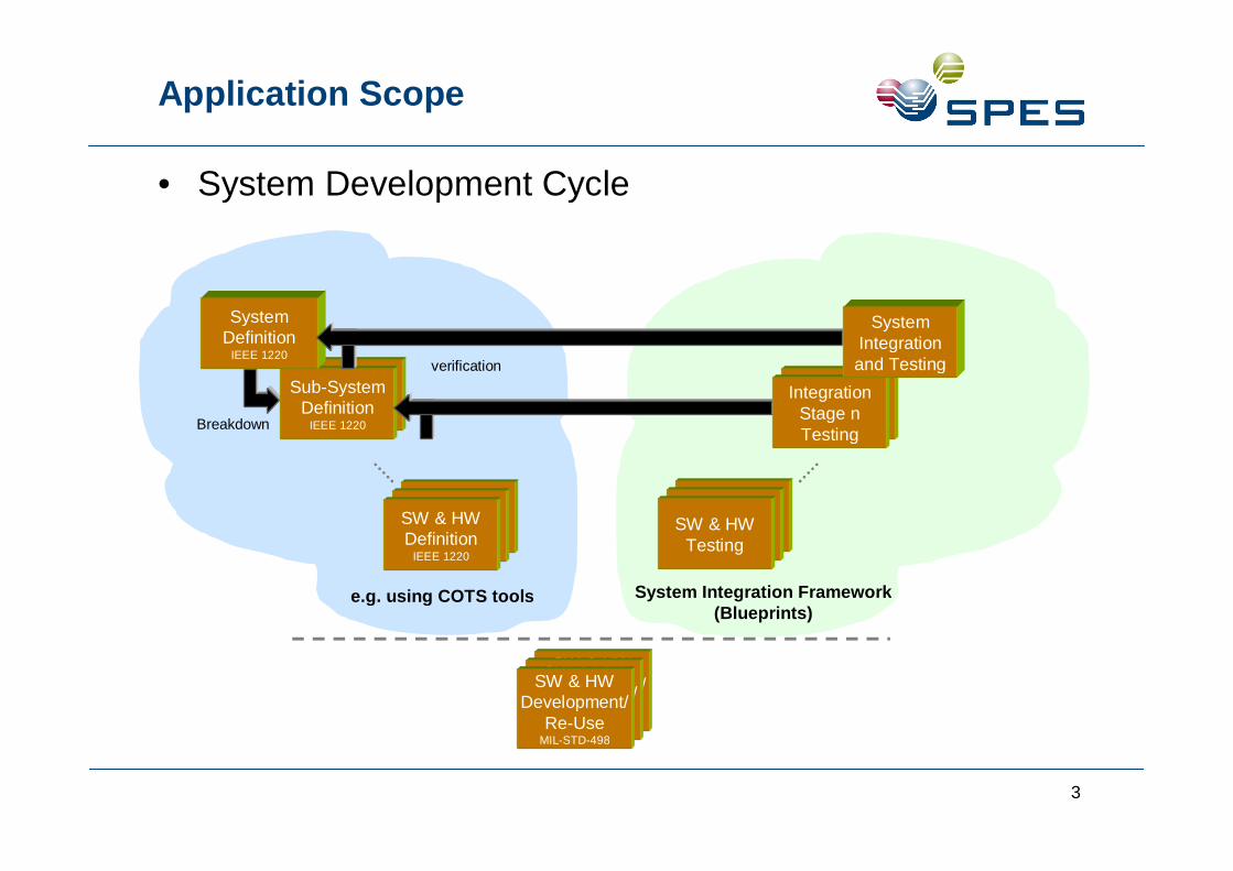
• System Development Cycle
SW & HWDevelopment/
Re-UseMIL-STD-498
SW & HWDevelopment/
Re-UseMIL-STD-498
SW & HWDevelopment/
Re-UseMIL-STD-498
SW & HWIntegration
Testing
SW & HWIntegration
Testing
SW & HWTesting
Breakdown
SW & HWDefinition
IEEE 1220
SW & HWDefinition
IEEE 1220
SW & HWDefinition
IEEE 1220
Sub-SystemDefinition
IEEE 1220
Sub-SystemDefinition
IEEE 1220
SystemDefinition
IEEE 1220verification
IntegrationStage nTesting
IntegrationStage nTesting
SystemIntegrationand Testing
e.g. using COTS tools System Integration Framework(Blueprints)
4
Blueprint Based Development Process (1)
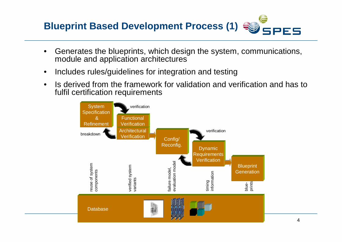
• Generates the blueprints, which design the system, communications,module and application architectures
• Includes rules/guidelines for integration and testing
• Is derived from the framework for validation and verification and has tofulfil certification requirements
SystemSpecification
&Refinement
Database
verified
syst
em
variants
reuse
of
syst
em
com
ponents
failu
rem
odel,
evalu
ation
model
tim
ing
info
rmation
blu
e-
pri
nts
breakdownArchitecturalVerification
FunctionalVerification
verification
Config/Reconfig.
DynamicRequirements
Verification
verification
BlueprintGeneration
5
• Configuration Blueprint
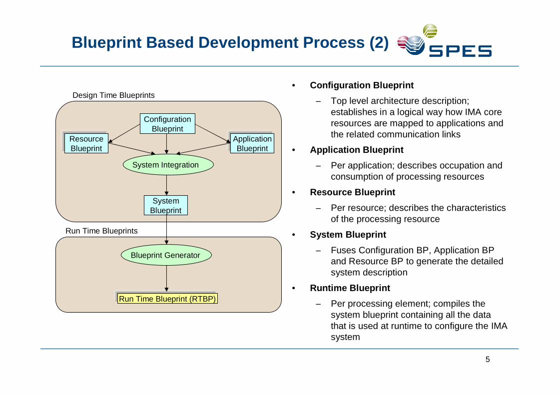
– Top level architecture description;establishes in a logical way how IMA coreresources are mapped to applications andthe related communication links
• Application Blueprint
– Per application; describes occupation andconsumption of processing resources
• Resource Blueprint
– Per resource; describes the characteristicsof the processing resource
• System Blueprint
– Fuses Configuration BP, Application BPand Resource BP to generate the detailedsystem description
• Runtime Blueprint
– Per processing element; compiles thesystem blueprint containing all the datathat is used at runtime to configure the IMAsystem
ResourceBlueprint
ConfigurationBlueprint
ApplicationBlueprint
SystemBlueprint
System Integration
Blueprint Generator
Run Time Blueprint (RTBP)
Run Time Blueprints
Design Time Blueprints
Blueprint Based Development Process (2)
6
Integration Steps
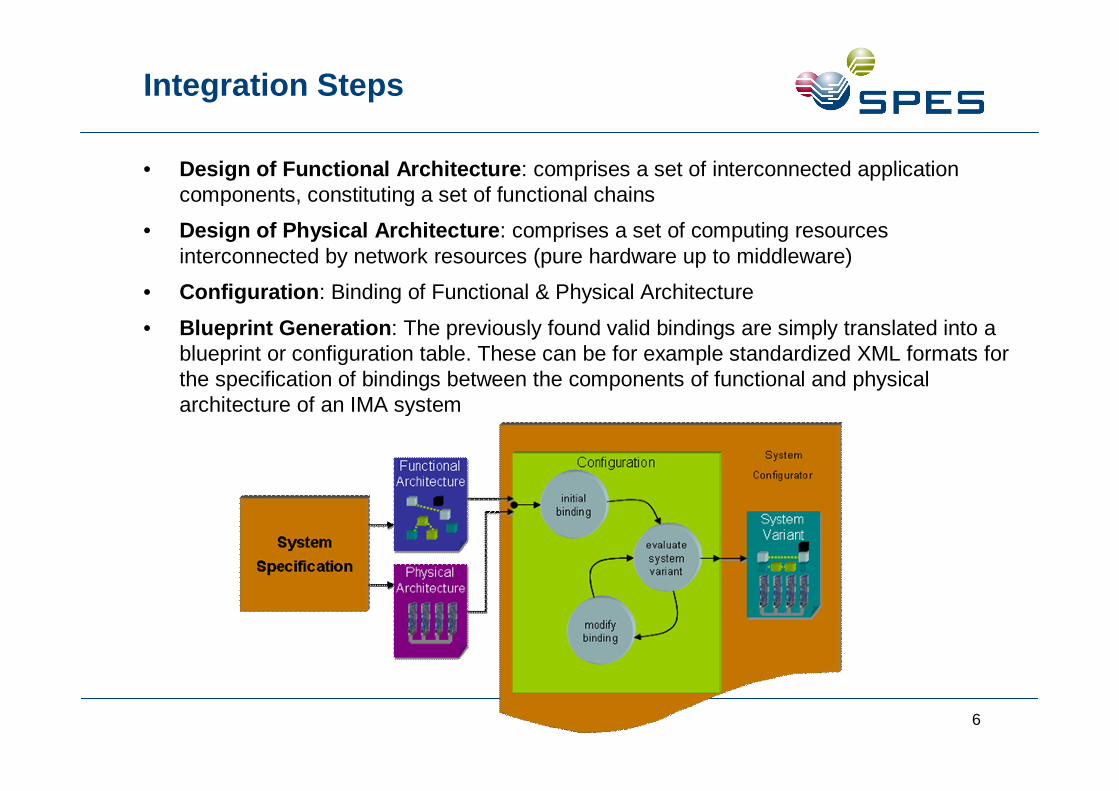
• Design of Functional Architecture: comprises a set of interconnected applicationcomponents, constituting a set of functional chains
• Design of Physical Architecture: comprises a set of computing resourcesinterconnected by network resources (pure hardware up to middleware)
• Configuration: Binding of Functional & Physical Architecture
• Blueprint Generation: The previously found valid bindings are simply translated into ablueprint or configuration table. These can be for example standardized XML formats forthe specification of bindings between the components of functional and physicalarchitecture of an IMA system