Embed Size (px)
Citation preview
J. Schneider Elektrotechnik GmbH
Helmholtzstrasse 13
D-77652 Offenburg
Germany
Tel. +49 / (0) 781 / 2 06 -0
Fax +49 / (0) 7 81 / 2 53 18
www.j-schneider.de
Jörg
Sch
aars
chm
idt D
ipl.-
Des
igne
r · w
ww
.j-sc
haar
schm
idt.d
e · Ä
nder
unge
n vo
rbeh
alte
n · M
odifi
catio
ns p
ossi
ble
· 111
7
DC-USV Anlagen / BatterieanlagenDC-UPS systems / battery systems
DC-USV Anlagen 2 A - 600 A
Ultracap-Module 0,2 A - 600 A
DC-UPS systems 2 A - 600 A
Ultracap-modules 0,2 A - 600 A
Unterbrechungsfreie Gleichstromversorgungen
(DC-USV-Anlagen) gewährleisten die Aufrechter-
haltung des Betriebes von Maschinen und Anla-
gen oder einen kontrollierten Prozessstop bei
Stromversorgungsproblemen.
DC-USV: Allgemeines
DC-USV mit Ultrakondensatoren
Pufferzeiten DC-USV mit Ultrakondensatoren
Ladezeiten DC-USV mit Ultrakondensatoren
Puffermodule mit Superkondensatoren
Puffermodule mit Superkondensatoren AC-Eingang
Passive Ultrakondensatorgepufferte Stromversorgung
Lader für Ultracaps und Batterien
Primärgetaktete Netzgeräte
Schneider Kombinationen
DC-USV batteriegepuffert
DC-USV batteriegepuffert Offline
Lader für Batterien
AKKUTEC im Gehäuse
Software TECControl, paraTEC
Optionen
Schaltungsbeispiele
USV im Schaltschrank
Batterien
Sonderapplikationen
Wechselrichter
DC-UPS: in general
DC-UPS with ultra-capacitors
Buffer times DC-UPS with ultra-capacitors
Charging times DC-UPS of ultra-capacitors
Buffer-modules with ultra-capacitors
Buffer-modules with ultra-capacitors AC-input
Passive ultra-capacitor buffered power supplies
Charger for ultra-caps and batteries
Primary switched power supplies
Schneider-Combinations
DC-UPS battery buffered
Battery based Offline DC UPS System
Charger for batteries
AKKUTEC in cabinet
Software TECControl, paraTEC
Options
Circuit examples
UPS in cabinet
Batteries
Special applications
Inverter
3-4
5
6
7
8
9
10
11
12-13
14
15-19
20
21
22
23
24-25
26
27
28-29
30
31
Uninterruptable DC-power supplies
(DC-UPS-systems) ensure the continous operation
of machinery or a controlled process-shutdown in
case of power failures.
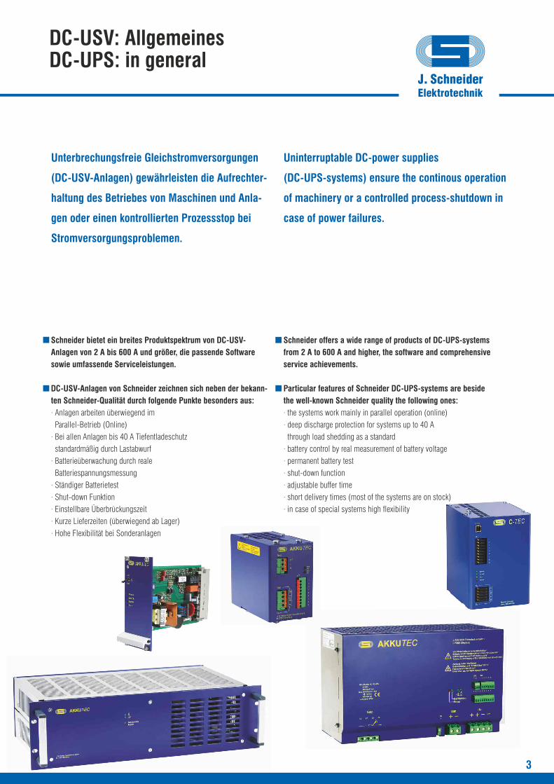
Schneider bietet ein breites Produktspektrum von DC-USV-
Anlagen von 2 A bis 600 A und größer, die passende Software
sowie umfassende Serviceleistungen.
DC-USV-Anlagen von Schneider zeichnen sich neben der bekann-
ten Schneider-Qualität durch folgende Punkte besonders aus:
· Anlagen arbeiten überwiegend im
Parallel-Betrieb (Online)
· Bei allen Anlagen bis 40 A Tiefentladeschutz
standardmäßig durch Lastabwurf
· Batterieüberwachung durch reale
Batteriespannungsmessung
· Ständiger Batterietest
· Shut-down Funktion
· Einstellbare Überbrückungszeit
· Kurze Lieferzeiten (überwiegend ab Lager)
· Hohe Flexibilität bei Sonderanlagen
Schneider offers a wide range of products of DC-UPS-systems
from 2 A to 600 A and higher, the software and comprehensive
service achievements.
Particular features of Schneider DC-UPS-systems are beside
the well-known Schneider quality the following ones:
· the systems work mainly in parallel operation (online)
· deep discharge protection for systems up to 40 A
through load shedding as a standard
· battery control by real measurement of battery voltage
· permanent battery test
· shut-down function
· adjustable buffer time
· short delivery times (most of the systems are on stock)
· in case of special systems high flexibility
2 3
InhaltContent
DC-USV: AllgemeinesDC-UPS: in general
Unterbrechungsfreie Gleichstromversorgungen
(DC-USV-Anlagen) gewährleisten die Aufrechter-
haltung des Betriebes von Maschinen und Anla-
gen oder einen kontrollierten Prozessstop bei
Stromversorgungsproblemen.
DC-USV: Allgemeines
DC-USV mit Ultrakondensatoren
Pufferzeiten DC-USV mit Ultrakondensatoren
Ladezeiten DC-USV mit Ultrakondensatoren
Puffermodule mit Superkondensatoren
Puffermodule mit Superkondensatoren AC-Eingang
Passive Ultrakondensatorgepufferte Stromversorgung
Lader für Ultracaps und Batterien
Primärgetaktete Netzgeräte
Schneider Kombinationen
DC-USV batteriegepuffert
DC-USV batteriegepuffert Offline
Lader für Batterien
AKKUTEC im Gehäuse
Software TECControl, paraTEC
Optionen
Schaltungsbeispiele
USV im Schaltschrank
Batterien
Sonderapplikationen
Wechselrichter
DC-UPS: in general
DC-UPS with ultra-capacitors
Buffer times DC-UPS with ultra-capacitors
Charging times DC-UPS of ultra-capacitors
Buffer-modules with ultra-capacitors
Buffer-modules with ultra-capacitors AC-input
Passive ultra-capacitor buffered power supplies
Charger for ultra-caps and batteries
Primary switched power supplies
Schneider-Combinations
DC-UPS battery buffered
Battery based Offline DC UPS System
Charger for batteries
AKKUTEC in cabinet
Software TECControl, paraTEC
Options
Circuit examples
UPS in cabinet
Batteries
Special applications
Inverter
3-4
5
6
7
8
9
10
11
12-13
14
15-19
20
21
22
23
24-25
26
27
28-29
30
31
Uninterruptable DC-power supplies
(DC-UPS-systems) ensure the continous operation
of machinery or a controlled process-shutdown in
case of power failures.
Schneider bietet ein breites Produktspektrum von DC-USV-
Anlagen von 2 A bis 600 A und größer, die passende Software
sowie umfassende Serviceleistungen.
DC-USV-Anlagen von Schneider zeichnen sich neben der bekann-
ten Schneider-Qualität durch folgende Punkte besonders aus:
· Anlagen arbeiten überwiegend im
Parallel-Betrieb (Online)
· Bei allen Anlagen bis 40 A Tiefentladeschutz
standardmäßig durch Lastabwurf
· Batterieüberwachung durch reale
Batteriespannungsmessung
· Ständiger Batterietest
· Shut-down Funktion
· Einstellbare Überbrückungszeit
· Kurze Lieferzeiten (überwiegend ab Lager)
· Hohe Flexibilität bei Sonderanlagen
Schneider offers a wide range of products of DC-UPS-systems
from 2 A to 600 A and higher, the software and comprehensive
service achievements.
Particular features of Schneider DC-UPS-systems are beside
the well-known Schneider quality the following ones:
· the systems work mainly in parallel operation (online)
· deep discharge protection for systems up to 40 A
through load shedding as a standard
· battery control by real measurement of battery voltage
· permanent battery test
· shut-down function
· adjustable buffer time
· short delivery times (most of the systems are on stock)
· in case of special systems high flexibility
2 3
InhaltContent
DC-USV: AllgemeinesDC-UPS: in general
DC-USV
DC-UPS D1 K1
K1
F1
Batterie
Battery
Last
Load
offl
ine
onlin
e
4 5
DC-USV: AllgemeinesDC-UPS: in general
DC-USV mit UltrakondensatorenDC-UPS with ultra-capacitors
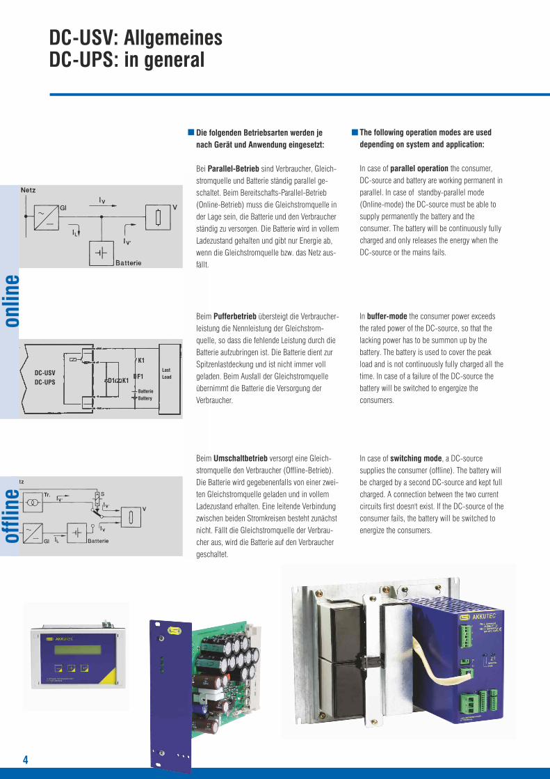
Die folgenden Betriebsarten werden je
nach Gerät und Anwendung eingesetzt:
Bei Parallel-Betrieb sind Verbraucher, Gleich-
stromquelle und Batterie ständig parallel ge-
schaltet. Beim Bereitschafts-Parallel-Betrieb
(Online-Betrieb) muss die Gleichstromquelle in
der Lage sein, die Batterie und den Verbraucher
ständig zu versorgen. Die Batterie wird in vollem
Ladezustand gehalten und gibt nur Energie ab,
wenn die Gleichstromquelle bzw. das Netz aus-
fällt.
Beim Pufferbetrieb übersteigt die Verbraucher-
leistung die Nennleistung der Gleichstrom-
quelle, so dass die fehlende Leistung durch die
Batterie aufzubringen ist. Die Batterie dient zur
Spitzenlastdeckung und ist nicht immer voll
geladen. Beim Ausfall der Gleichstromquelle
übernimmt die Batterie die Versorgung der
Verbraucher.
The following operation modes are used
depending on system and application:
In case of parallel operation the consumer,
DC-source and battery are working permanent in
parallel. In case of standby-parallel mode
(Online-mode) the DC-source must be able to
supply permanently the battery and the
consumer. The battery will be continuously fully
charged and only releases the energy when the
DC-source or the mains fails.
In buffer-mode the consumer power exceeds
the rated power of the DC-source, so that the
lacking power has to be summon up by the
battery. The battery is used to cover the peak
load and is not continuously fully charged all the
time. In case of a failure of the DC-source the
battery will be switched to engergize the
consumers.
In case of switching mode, a DC-source
supplies the consumer (offline). The battery will
be charged by a second DC-source and kept full
charged. A connection between the two current
circuits first doesn't exist. If the DC-source of the
consumer fails, the battery will be switched to
energize the consumers.
Beim Umschaltbetrieb versorgt eine Gleich-
stromquelle den Verbraucher (Offline-Betrieb).
Die Batterie wird gegebenenfalls von einer zwei-
ten Gleichstromquelle geladen und in vollem
Ladezustand erhalten. Eine leitende Verbindung
zwischen beiden Stromkreisen besteht zunächst
nicht. Fällt die Gleichstromquelle der Verbrau-
cher aus, wird die Batterie auf den Verbraucher
geschaltet.
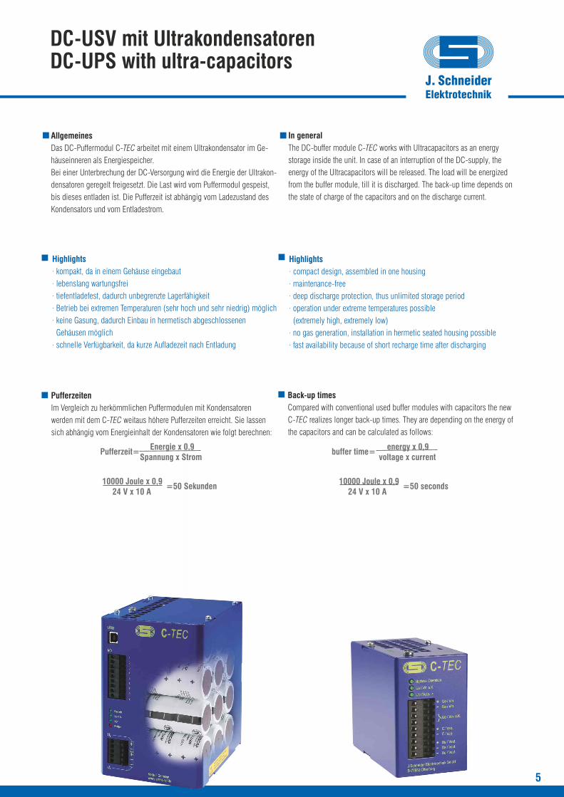
Allgemeines
Das DC-Puffermodul C-TEC arbeitet mit einem Ultrakondensator im Ge-
häuseinneren als Energiespeicher.
Bei einer Unterbrechung der DC-Versorgung wird die Energie der Ultrakon-
densatoren geregelt freigesetzt. Die Last wird vom Puffermodul gespeist,
bis dieses entladen ist. Die Pufferzeit ist abhängig vom Ladezustand des
Kondensators und vom Entladestrom.
Highlights
· kompakt, da in einem Gehäuse eingebaut
· lebenslang wartungsfrei
· tiefentladefest, dadurch unbegrenzte Lagerfähigkeit
· Betrieb bei extremen Temperaturen (sehr hoch und sehr niedrig) möglich
· keine Gasung, dadurch Einbau in hermetisch abgeschlossenen
Gehäusen möglich
· schnelle Verfügbarkeit, da kurze Aufladezeit nach Entladung
Pufferzeiten
Im Vergleich zu herkömmlichen Puffermodulen mit Kondensatoren
werden mit dem C-TEC weitaus höhere Pufferzeiten erreicht. Sie lassen
sich abhängig vom Energieinhalt der Kondensatoren wie folgt berechnen:
Back-up times
Compared with conventional used buffer modules with capacitors the new
C-TEC realizes longer back-up times. They are depending on the energy of
the capacitors and can be calculated as follows:
Highlights
· compact design, assembled in one housing
· maintenance-free
· deep discharge protection, thus unlimited storage period
· operation under extreme temperatures possible
(extremely high, extremely low)
· no gas generation, installation in hermetic seated housing possible
· fast availability because of short recharge time after discharging
In general
The DC-buffer module C-TEC works with Ultracapacitors as an energy
storage inside the unit. In case of an interruption of the DC-supply, the
energy of the Ultracapacitors will be released. The load will be energized
from the buffer module, till it is discharged. The back-up time depends on
the state of charge of the capacitors and on the discharge current.
=50 Sekunden10000 Joule x 0,9
24 V x 10 A=50 seconds
10000 Joule x 0,924 V x 10 A
Pufferzeit=Energie x 0,9
Spannung x Strombuffer time=
energy x 0,9voltage x current
DC-USV
DC-UPS D1 K1
K1
F1
Batterie
Battery
Last
Load
offl
ine
onlin
e
4 5
DC-USV: AllgemeinesDC-UPS: in general
DC-USV mit UltrakondensatorenDC-UPS with ultra-capacitors
Die folgenden Betriebsarten werden je
nach Gerät und Anwendung eingesetzt:
Bei Parallel-Betrieb sind Verbraucher, Gleich-
stromquelle und Batterie ständig parallel ge-
schaltet. Beim Bereitschafts-Parallel-Betrieb
(Online-Betrieb) muss die Gleichstromquelle in
der Lage sein, die Batterie und den Verbraucher
ständig zu versorgen. Die Batterie wird in vollem
Ladezustand gehalten und gibt nur Energie ab,
wenn die Gleichstromquelle bzw. das Netz aus-
fällt.
Beim Pufferbetrieb übersteigt die Verbraucher-
leistung die Nennleistung der Gleichstrom-
quelle, so dass die fehlende Leistung durch die
Batterie aufzubringen ist. Die Batterie dient zur
Spitzenlastdeckung und ist nicht immer voll
geladen. Beim Ausfall der Gleichstromquelle
übernimmt die Batterie die Versorgung der
Verbraucher.
The following operation modes are used
depending on system and application:
In case of parallel operation the consumer,
DC-source and battery are working permanent in
parallel. In case of standby-parallel mode
(Online-mode) the DC-source must be able to
supply permanently the battery and the
consumer. The battery will be continuously fully
charged and only releases the energy when the
DC-source or the mains fails.
In buffer-mode the consumer power exceeds
the rated power of the DC-source, so that the
lacking power has to be summon up by the
battery. The battery is used to cover the peak
load and is not continuously fully charged all the
time. In case of a failure of the DC-source the
battery will be switched to engergize the
consumers.
In case of switching mode, a DC-source
supplies the consumer (offline). The battery will
be charged by a second DC-source and kept full
charged. A connection between the two current
circuits first doesn't exist. If the DC-source of the
consumer fails, the battery will be switched to
energize the consumers.
Beim Umschaltbetrieb versorgt eine Gleich-
stromquelle den Verbraucher (Offline-Betrieb).
Die Batterie wird gegebenenfalls von einer zwei-
ten Gleichstromquelle geladen und in vollem
Ladezustand erhalten. Eine leitende Verbindung
zwischen beiden Stromkreisen besteht zunächst
nicht. Fällt die Gleichstromquelle der Verbrau-
cher aus, wird die Batterie auf den Verbraucher
geschaltet.
Allgemeines
Das DC-Puffermodul C-TEC arbeitet mit einem Ultrakondensator im Ge-
häuseinneren als Energiespeicher.
Bei einer Unterbrechung der DC-Versorgung wird die Energie der Ultrakon-
densatoren geregelt freigesetzt. Die Last wird vom Puffermodul gespeist,
bis dieses entladen ist. Die Pufferzeit ist abhängig vom Ladezustand des
Kondensators und vom Entladestrom.
Highlights
· kompakt, da in einem Gehäuse eingebaut
· lebenslang wartungsfrei
· tiefentladefest, dadurch unbegrenzte Lagerfähigkeit
· Betrieb bei extremen Temperaturen (sehr hoch und sehr niedrig) möglich
· keine Gasung, dadurch Einbau in hermetisch abgeschlossenen
Gehäusen möglich
· schnelle Verfügbarkeit, da kurze Aufladezeit nach Entladung
Pufferzeiten
Im Vergleich zu herkömmlichen Puffermodulen mit Kondensatoren
werden mit dem C-TEC weitaus höhere Pufferzeiten erreicht. Sie lassen
sich abhängig vom Energieinhalt der Kondensatoren wie folgt berechnen:
Back-up times
Compared with conventional used buffer modules with capacitors the new
C-TEC realizes longer back-up times. They are depending on the energy of
the capacitors and can be calculated as follows:
Highlights
· compact design, assembled in one housing
· maintenance-free
· deep discharge protection, thus unlimited storage period
· operation under extreme temperatures possible
(extremely high, extremely low)
· no gas generation, installation in hermetic seated housing possible
· fast availability because of short recharge time after discharging
In general
The DC-buffer module C-TEC works with Ultracapacitors as an energy
storage inside the unit. In case of an interruption of the DC-supply, the
energy of the Ultracapacitors will be released. The load will be energized
from the buffer module, till it is discharged. The back-up time depends on
the state of charge of the capacitors and on the discharge current.
=50 Sekunden10000 Joule x 0,9
24 V x 10 A=50 seconds
10000 Joule x 0,924 V x 10 A
Pufferzeit=Energie x 0,9
Spannung x Strombuffer time=
energy x 0,9voltage x current
6 7
Pufferzeiten DC-USV mit UltrakondensatorenBuffer times DC-UPS with ultra-capacitors
Ladezeiten DC-USV mit UltrakondensatorenCharging times DC-UPS of ultra-capacitors
C-TEC
AC C-TEC
C-TEC
AC C-TEC
C-TEC
AC C-TEC
1203-1
1203-1
1203-1
1203-1
2420-8
2420-8
2403-1
2403-1
2403-1
2403-1
+ CEM 8
+ CEM 8
2405-5
*
2410-1
*
+ CEM 8
2408-20
*
2410-10
*
+ CEM 16
2410-1
*
2420-8
2420-8
1225 P
*
2410-10
2410-10
2425 P
*
4815 P
*
+ CEM 1
+ CEM 1
2405-5
*
+ CEM 16
+ CEM 16
+ CEM 2
+ CEM 2
2408-20
*
2440 P
*
0,5
1
1,5
2
3
5
8
10
3
5
8
10
15
20
0,5
1
1,5
2
3
5
8
10
15
20
30
40
150
75
50
37,5
25
23
600
300
200
150
100
60
37,5
30
20
15
75
37,5
25
19
12,5
12
1200
600
400
300
200
120
75
60
40
30
150
75
50
38
25
57
34
1800
900
600
450
300
180
112,5
90
60
45
225
112,5
75
57
37,5
225
135
85
333
167
111
83
55,5
33
21
17
11
8
5,5
4
375
187,5
125
94
62,5
37,5
12
7
5
4
666
333
222
167
111
66
42
33
22
17
11
8
1500
750
500
375
250
150
94
113
68
43
34
999
500
333
250
166,5
99
63
50
33
25
16,5
12
75
37,5
25
18,75
12,5
7,5
4,5
3,75
90
54
34
27
18
14
110
55
35
27,5
18
10
6
5
3
2
1,5
750
375
250
187,5
125
75
45
37,5
115
60
40
30
19,5
10,5
6,5
5
3,5
2
50
25
17
12,5
8
4,5
3
2
1,5
Strom · current [A] Zeit in Sekunden · time in seconds
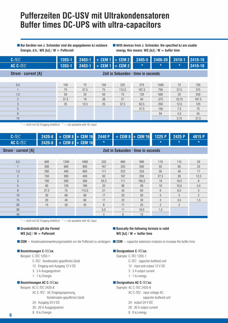
Bezeichnungen C-TECxx:
Beispiel: C-TEC 1203-1
Grundsätzlich gilt die Formel
WS [kJ] / W = Pufferzeit
Bei Geräten von J. Schneider sind die angegebenen kJ nutzbare
Energie, d.h.: WS [kJ] / W = Pufferzeit
CEM = Kondensatorerweiterungsmodelle um die Pufferzeit zu verlängern CEM = capacitor extension modules to increase the buffer time
Basically the following formula is valid
WS [kJ] / W = buffer time
With devices from J. Schneider, the specified kJ are usable
energy, this means: WS [kJ] / W = buffer time
Designations C-TECxx:
Example: C-TEC 1203-1
Bezeichnungen AC C-TECxx:
Beispiel: AC C-TEC 2420-8
Designations AC C-TECxx:
Example: AC C-TEC 2420-8
C-TEC: Kondensator-gepuffertes Gerät
12: Eingang und Ausgang 12 V DC
3: 3 A Ausgangsstrom
1: 1 kJ Energie
C-TEC: capacitor-buffered unit
12: input and output 12 V DC
3: 3 A output current
1: 1 kJ energy
AC C-TEC: AC Eingangsspannung,
Kondensator-gepuffertes Gerät
24: Ausgang 24 V DC
20: 20 A Ausgangsstrom
8: 8 kJ Energie
AC C-TEC: input voltage AC,
capacitor-buffered unit
24: output 24 V DC
20: 20 A output current
8: 8 kJ energy
Strom · current [A] Zeit in Sekunden · time in seconds
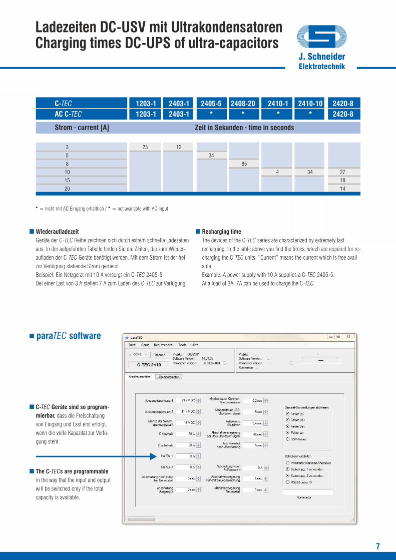
paraTEC software
Wiederaufladezeit
Geräte der C-TEC Reihe zeichnen sich durch extrem schnelle Ladezeiten
aus. In der aufgeführten Tabelle finden Sie die Zeiten, die zum Wieder-
aufladen der C-TEC Geräte benötigt werden. Mit dem Strom ist der frei
zur Verfügung stehende Strom gemeint.
Beispiel: Ein Netzgerät mit 10 A versorgt ein C-TEC 2405-5.
Bei einer Last von 3 A stehen 7 A zum Laden des C-TEC zur Verfügung.
C-TEC Geräte sind so program-
mierbar, dass die Freischaltung
von Eingang und Last erst erfolgt,
wenn die volle Kapazität zur Verfü-
gung steht.
The C-TECs are programmable
in the way that the input and output
will be switched only if the total
capacity is available.
Strom · current [A] Zeit in Sekunden · time in seconds
* = nicht mit AC Eingang erhältlich / * = not available with AC input
* = nicht mit AC Eingang erhältlich * = not available with AC input
* = nicht mit AC Eingang erhältlich * = not available with AC input
Recharging time
The devices of the C-TEC series are characterized by extremely fast
recharging. In the table above you find the times, which are required for re-
charging the C-TEC units. “Current” means the current which is free avail-
able.
Example: A power supply with 10 A supplies a C-TEC 2405-5.
At a load of 3A, 7A can be used to charge the C-TEC.
6 7
Pufferzeiten DC-USV mit UltrakondensatorenBuffer times DC-UPS with ultra-capacitors
Ladezeiten DC-USV mit UltrakondensatorenCharging times DC-UPS of ultra-capacitors
C-TEC
AC C-TEC
C-TEC
AC C-TEC
C-TEC
AC C-TEC
1203-1
1203-1
1203-1
1203-1
2420-8
2420-8
2403-1
2403-1
2403-1
2403-1
+ CEM 8
+ CEM 8
2405-5
*
2410-1
*
+ CEM 8
2408-20
*
2410-10
*
+ CEM 16
2410-1
*
2420-8
2420-8
1225 P
*
2410-10
2410-10
2425 P
*
4815 P
*
+ CEM 1
+ CEM 1
2405-5
*
+ CEM 16
+ CEM 16
+ CEM 2
+ CEM 2
2408-20
*
2440 P
*
0,5
1
1,5
2
3
5
8
10
3
5
8
10
15
20
0,5
1
1,5
2
3
5
8
10
15
20
30
40
150
75
50
37,5
25
23
600
300
200
150
100
60
37,5
30
20
15
75
37,5
25
19
12,5
12
1200
600
400
300
200
120
75
60
40
30
150
75
50
38
25
57
34
1800
900
600
450
300
180
112,5
90
60
45
225
112,5
75
57
37,5
225
135
85
333
167
111
83
55,5
33
21
17
11
8
5,5
4
375
187,5
125
94
62,5
37,5
12
7
5
4
666
333
222
167
111
66
42
33
22
17
11
8
1500
750
500
375
250
150
94
113
68
43
34
999
500
333
250
166,5
99
63
50
33
25
16,5
12
75
37,5
25
18,75
12,5
7,5
4,5
3,75
90
54
34
27
18
14
110
55
35
27,5
18
10
6
5
3
2
1,5
750
375
250
187,5
125
75
45
37,5
115
60
40
30
19,5
10,5
6,5
5
3,5
2
50
25
17
12,5
8
4,5
3
2
1,5
Strom · current [A] Zeit in Sekunden · time in seconds
Bezeichnungen C-TECxx:
Beispiel: C-TEC 1203-1
Grundsätzlich gilt die Formel
WS [kJ] / W = Pufferzeit
Bei Geräten von J. Schneider sind die angegebenen kJ nutzbare
Energie, d.h.: WS [kJ] / W = Pufferzeit
CEM = Kondensatorerweiterungsmodelle um die Pufferzeit zu verlängern CEM = capacitor extension modules to increase the buffer time
Basically the following formula is valid
WS [kJ] / W = buffer time
With devices from J. Schneider, the specified kJ are usable
energy, this means: WS [kJ] / W = buffer time
Designations C-TECxx:
Example: C-TEC 1203-1
Bezeichnungen AC C-TECxx:
Beispiel: AC C-TEC 2420-8
Designations AC C-TECxx:
Example: AC C-TEC 2420-8
C-TEC: Kondensator-gepuffertes Gerät
12: Eingang und Ausgang 12 V DC
3: 3 A Ausgangsstrom
1: 1 kJ Energie
C-TEC: capacitor-buffered unit
12: input and output 12 V DC
3: 3 A output current
1: 1 kJ energy
AC C-TEC: AC Eingangsspannung,
Kondensator-gepuffertes Gerät
24: Ausgang 24 V DC
20: 20 A Ausgangsstrom
8: 8 kJ Energie
AC C-TEC: input voltage AC,
capacitor-buffered unit
24: output 24 V DC
20: 20 A output current
8: 8 kJ energy
Strom · current [A] Zeit in Sekunden · time in seconds
paraTEC software
Wiederaufladezeit
Geräte der C-TEC Reihe zeichnen sich durch extrem schnelle Ladezeiten
aus. In der aufgeführten Tabelle finden Sie die Zeiten, die zum Wieder-
aufladen der C-TEC Geräte benötigt werden. Mit dem Strom ist der frei
zur Verfügung stehende Strom gemeint.
Beispiel: Ein Netzgerät mit 10 A versorgt ein C-TEC 2405-5.
Bei einer Last von 3 A stehen 7 A zum Laden des C-TEC zur Verfügung.
C-TEC Geräte sind so program-
mierbar, dass die Freischaltung
von Eingang und Last erst erfolgt,
wenn die volle Kapazität zur Verfü-
gung steht.
The C-TECs are programmable
in the way that the input and output
will be switched only if the total
capacity is available.
Strom · current [A] Zeit in Sekunden · time in seconds
* = nicht mit AC Eingang erhältlich / * = not available with AC input
* = nicht mit AC Eingang erhältlich * = not available with AC input
* = nicht mit AC Eingang erhältlich * = not available with AC input
Recharging time
The devices of the C-TEC series are characterized by extremely fast
recharging. In the table above you find the times, which are required for re-
charging the C-TEC units. “Current” means the current which is free avail-
able.
Example: A power supply with 10 A supplies a C-TEC 2405-5.
At a load of 3A, 7A can be used to charge the C-TEC.
8 9
Puffermodule mit SuperkondensatorenBuffer-modules with ultra-capacitors
2403-05 2403-1 2403 USB 2403 K 1203-1
2405-5 / 1205-5
2408-20 /1208-20
2410-1 /1210-1
2410-10 /1210-10
2420-8 C-TEC
C-TEC
Eingang
Eingangsnennspannung
Gespeicherte Energie in Ws
Ausgang
Ausgangsspannung im Pufferbetrieb
Ausgangsnennstrom
Abschaltung bei Überlast
Strombegrenzung
Wirkungsgrad Ua=23,5 V DC, Ia=INenn
Allgemeine Daten
Anschlussart Eingang UE
Anschlussart Ausgang UA
Anschlussart Meldungen I/O
Schutzart
Gewicht
Lagertemperatur
Umgebungstemperatur
Abmessungen in mm
Eingang
Eingangsnennspannung
Gespeicherte Energie in Ws
Ausgang
Ausgangsspannung im Pufferbetrieb
Ausgangsnennstrom
Abschaltung bei Überlast
Strombegrenzung
Wirkungsgrad Ua=23,5 V DC, Ia=INenn
IPC-Funktion
Allgemeine Daten
Anschlussart Eingang UE
Anschlussart Ausgang UA
Anschlussart Meldungen I/O
Schutzart
Gewicht
Lagertemperatur
Umgebungstemperatur
Abmessungen in mm
Input
nominal input voltage
stored energy in Ws
Output
output voltage in buffer-mode
nominal output current
overload shutdown
current limitation
efficiency Ua=23,5 V DC, Ia= Inom
General data
type of connection input UE
type of connection output UA
type of connection status I/O
type of protection
weight
storage temperature
ambient temperature
dimensions in mm
Input
nominal input voltage
stored energy in Ws
Output
output voltage in buffer-mode
nominal output current
overload shutdown
current limitation
efficiency Ua=23,5 V DC, Ia= Inom
IPC function
General data
type of connection input UE
type of connection output UA
type of connection status I/O
type of protection
weight
storage temperature
ambient temperature
dimensions in mm
24 V DC +/- 20%
500
23 V +/- 2 %
3 A
ja/yes
> 90 %
1 mm²
1 mm²
1 mm²
IP 20
0,5 kg
-40 /+60° C
-40 /+60° C
93x60x116
24 V DC +/- 20%
1000
23 V +/- 2 %
3 A
ja/yes
> 90 %
optional
H 15 Messerleiste
H 15 Messerleiste
H 15 Messerleiste
IP 20
0,3 kg
-40 /+60° C
-40 /+60° C
19" mit 3 HE&8TE
12 V DC +/- 20%
1000
11,5 V +/- 2 %
3 A
ja/yes
> 90 %
2,5 mm²
2,5 mm²
1 mm²
IP 20
0,55 kg
-40 /+60° C
-40 /+60° C
93x60x116
24 / 12 V DC
5000
23,5 V / 11,7 V
5 A
> 90 %
2,5 mm²
2,5 mm²
1 mm²
IP 20
1,7 kg
-40 /+60° C
-40 /+60° C
165x114x145
24 / 12 V DC
20000
23,5 V / 11,7 V
8 A
> 90 %
2,5 mm²
2,5 mm²
1 mm²
IP 20
3,5 kg
-40 /+60° C
-40 /+60° C
165x184x145
24 / 12 V DC
1000
23,5 V / 11,7 V
10 A
> 90 %
2,5 mm²
2,5 mm²
1 mm²
IP 20
1,2 kg
-40 /+60° C
-40 /+60° C
165x70x138
24 / 12 V DC
10000
23,5 V / 11,7 V
10 A
> 90 %
2,5 mm²
2,5 mm²
1 mm²
IP 20
2,1 kg
-40 /+60° C
-40 /+60° C
165x114x145
24 V DC
8000
23,2 V
20 A
ca. 90 %
4 mm²
4 mm²
1,5 mm²
IP 20
2,2 kg
-40 /+60° C
-40 /+60° C
192x84x192
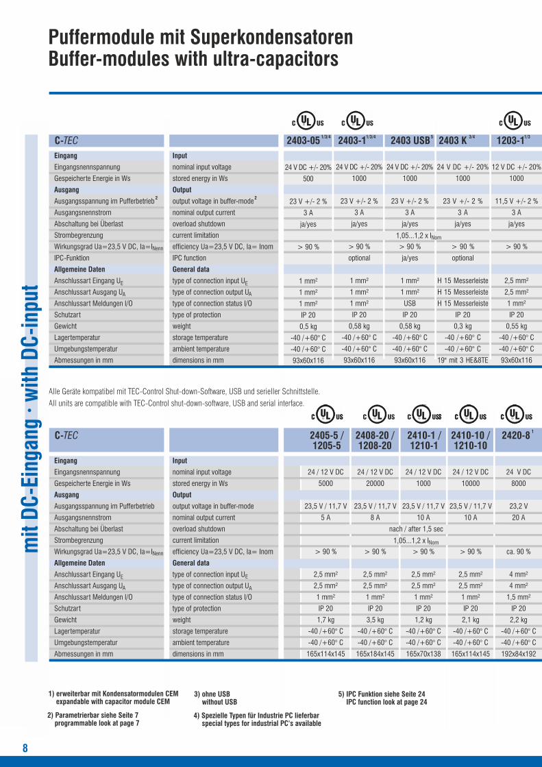
Alle Geräte kompatibel mit TEC-Control Shut-down-Software, USB und serieller Schnittstelle.
All units are compatible with TEC-Control shut-down-software, USB and serial interface.
1,05...1,2 x INom
1,05...1,2 x INom
1) erweiterbar mit Kondensatormodulen CEM expandable with capacitor module CEM
2) Parametrierbar siehe Seite 7 programmable look at page 7
3) ohne USB without USB
5) IPC Funktion siehe Seite 24 IPC function look at page 24
4) Spezielle Typen für Industrie PC lieferbar special types for industrial PC‘s available
mit
DC
-Ein
gang
· w
ith
DC
-inp
ut
1/3/4
22
1
1/3/4 5 3/4 1/3
nach / after 1,5 sec
2403-1
2410-10 2420-8
1203-1
AC C-TEC
AC C-TEC
Eingang
Eingangsnennspannung
Gespeicherte Energie in Ws
Ausgang
Ausgangsspannung im Pufferbetrieb
Ausgangsnennstrom
Strombegrenzung
Wirkungsgrad Ua=23,5 V DC, Ia=INenn
Allgemeine Daten
Anschlussart Eingang UE
Anschlussart Ausgang UA
Anschlussart Meldungen I/O
Schutzart
Gewicht
Lagertemperatur
Umgebungstemperatur
Abmessungen in mm
Input
nominal input voltage
stored energy in Ws
Output
output voltage in buffer-mode
nominal output current
current limitation
efficiency Ua=23, V DC, Ia= Inom
General data
type of connection input UE
type of connection output UA
type of connection status I/O
type of protection
weight
storage temperature
ambient temperature
dimensions in mm
115-230 V AC
1000
23,5 V
3 A
-
ca./approx. 90 %
2,5 mm²
2,5 mm²
1 mm²
IP 20
0,9 kg
-40 /+60° C
-40 /+60°
153x72x130
100 - 240 V AC
10000
23,5 V
10 A
ca./approx. 90 %
2,5 mm²
2,5 mm²
1 mm²
IP 20
3,0 kg
-40 /+70° C
-25 /+60° C
165x184x145
3x 400 - 500 V AC
8000
23,0 V
20 A
ca./approx. 90 %
2,5 mm²
4 mm²
1,5 mm²
IP 20
3,5 kg
-40 /+70° C
-25 /+60° C
192x170x198
115-230 V AC
1000
11,5 V
3 A
-
ca./approx. 90 %
2,5 mm²
2,5 mm²
1 mm²
IP 20
0,86 kg
-40 /+60° C
-40 /+60°
153x72x130
1,05...1,2 x INom
1,05...1,2 x INom
mit
AC
-Ein
gang
· w
ith
AC
-inp
ut
1/2 1/2
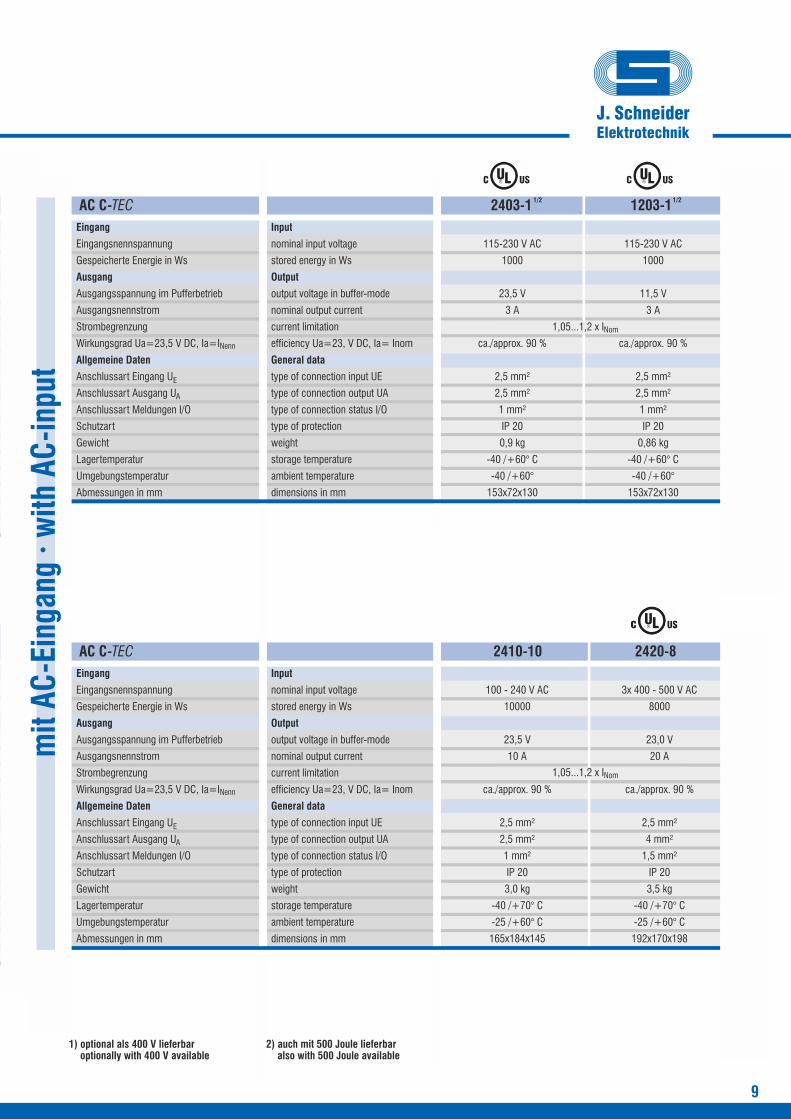
1) optional als 400 V lieferbar optionally with 400 V available
2) auch mit 500 Joule lieferbar also with 500 Joule available
24 V DC +/- 20%
1000
23 V +/- 2 %
3 A
ja/yes
> 90 %
optional
1 mm²
1 mm²
1 mm²
IP 20
0,58 kg
-40 /+60° C
-40 /+60° C
93x60x116
24 V DC +/- 20%
1000
23 V +/- 2 %
3 A
ja/yes
> 90 %
ja/yes
1 mm²
1 mm²
USB
IP 20
0,58 kg
-40 /+60° C
-40 /+60° C
93x60x116
8 9
Puffermodule mit SuperkondensatorenBuffer-modules with ultra-capacitors
2403-05 2403-1 2403 USB 2403 K 1203-1
2405-5 / 1205-5
2408-20 /1208-20
2410-1 /1210-1
2410-10 /1210-10
2420-8 C-TEC
C-TEC
Eingang
Eingangsnennspannung
Gespeicherte Energie in Ws
Ausgang
Ausgangsspannung im Pufferbetrieb
Ausgangsnennstrom
Abschaltung bei Überlast
Strombegrenzung
Wirkungsgrad Ua=23,5 V DC, Ia=INenn
Allgemeine Daten
Anschlussart Eingang UE
Anschlussart Ausgang UA
Anschlussart Meldungen I/O
Schutzart
Gewicht
Lagertemperatur
Umgebungstemperatur
Abmessungen in mm
Eingang
Eingangsnennspannung
Gespeicherte Energie in Ws
Ausgang
Ausgangsspannung im Pufferbetrieb
Ausgangsnennstrom
Abschaltung bei Überlast
Strombegrenzung
Wirkungsgrad Ua=23,5 V DC, Ia=INenn
IPC-Funktion
Allgemeine Daten
Anschlussart Eingang UE
Anschlussart Ausgang UA
Anschlussart Meldungen I/O
Schutzart
Gewicht
Lagertemperatur
Umgebungstemperatur
Abmessungen in mm
Input
nominal input voltage
stored energy in Ws
Output
output voltage in buffer-mode
nominal output current
overload shutdown
current limitation
efficiency Ua=23,5 V DC, Ia= Inom
General data
type of connection input UE
type of connection output UA
type of connection status I/O
type of protection
weight
storage temperature
ambient temperature
dimensions in mm
Input
nominal input voltage
stored energy in Ws
Output
output voltage in buffer-mode
nominal output current
overload shutdown
current limitation
efficiency Ua=23,5 V DC, Ia= Inom
IPC function
General data
type of connection input UE
type of connection output UA
type of connection status I/O
type of protection
weight
storage temperature
ambient temperature
dimensions in mm
24 V DC +/- 20%
500
23 V +/- 2 %
3 A
ja/yes
> 90 %
1 mm²
1 mm²
1 mm²
IP 20
0,5 kg
-40 /+60° C
-40 /+60° C
93x60x116
24 V DC +/- 20%
1000
23 V +/- 2 %
3 A
ja/yes
> 90 %
optional
H 15 Messerleiste
H 15 Messerleiste
H 15 Messerleiste
IP 20
0,3 kg
-40 /+60° C
-40 /+60° C
19" mit 3 HE&8TE
12 V DC +/- 20%
1000
11,5 V +/- 2 %
3 A
ja/yes
> 90 %
2,5 mm²
2,5 mm²
1 mm²
IP 20
0,55 kg
-40 /+60° C
-40 /+60° C
93x60x116
24 / 12 V DC
5000
23,5 V / 11,7 V
5 A
> 90 %
2,5 mm²
2,5 mm²
1 mm²
IP 20
1,7 kg
-40 /+60° C
-40 /+60° C
165x114x145
24 / 12 V DC
20000
23,5 V / 11,7 V
8 A
> 90 %
2,5 mm²
2,5 mm²
1 mm²
IP 20
3,5 kg
-40 /+60° C
-40 /+60° C
165x184x145
24 / 12 V DC
1000
23,5 V / 11,7 V
10 A
> 90 %
2,5 mm²
2,5 mm²
1 mm²
IP 20
1,2 kg
-40 /+60° C
-40 /+60° C
165x70x138
24 / 12 V DC
10000
23,5 V / 11,7 V
10 A
> 90 %
2,5 mm²
2,5 mm²
1 mm²
IP 20
2,1 kg
-40 /+60° C
-40 /+60° C
165x114x145
24 V DC
8000
23,2 V
20 A
ca. 90 %
4 mm²
4 mm²
1,5 mm²
IP 20
2,2 kg
-40 /+60° C
-40 /+60° C
192x84x192
Alle Geräte kompatibel mit TEC-Control Shut-down-Software, USB und serieller Schnittstelle.
All units are compatible with TEC-Control shut-down-software, USB and serial interface.
1,05...1,2 x INom
1,05...1,2 x INom
1) erweiterbar mit Kondensatormodulen CEM expandable with capacitor module CEM
2) Parametrierbar siehe Seite 7 programmable look at page 7
3) ohne USB without USB
5) IPC Funktion siehe Seite 24 IPC function look at page 24
4) Spezielle Typen für Industrie PC lieferbar special types for industrial PC‘s available
mit
DC
-Ein
gang
· w
ith
DC
-inp
ut
1/3/4
22
1
1/3/4 5 3/4 1/3
nach / after 1,5 sec
2403-1
2410-10 2420-8
1203-1
AC C-TEC
AC C-TEC
Eingang
Eingangsnennspannung
Gespeicherte Energie in Ws
Ausgang
Ausgangsspannung im Pufferbetrieb
Ausgangsnennstrom
Strombegrenzung
Wirkungsgrad Ua=23,5 V DC, Ia=INenn
Allgemeine Daten
Anschlussart Eingang UE
Anschlussart Ausgang UA
Anschlussart Meldungen I/O
Schutzart
Gewicht
Lagertemperatur
Umgebungstemperatur
Abmessungen in mm
Eingang
Eingangsnennspannung
Gespeicherte Energie in Ws
Ausgang
Ausgangsspannung im Pufferbetrieb
Ausgangsnennstrom
Strombegrenzung
Wirkungsgrad Ua=23,5 V DC, Ia=INenn
Allgemeine Daten
Anschlussart Eingang UE
Anschlussart Ausgang UA
Anschlussart Meldungen I/O
Schutzart
Gewicht
Lagertemperatur
Umgebungstemperatur
Abmessungen in mm
Input
nominal input voltage
stored energy in Ws
Output
output voltage in buffer-mode
nominal output current
current limitation
efficiency Ua=23, V DC, Ia= Inom
General data
type of connection input UE
type of connection output UA
type of connection status I/O
type of protection
weight
storage temperature
ambient temperature
dimensions in mm
Input
nominal input voltage
stored energy in Ws
Output
output voltage in buffer-mode
nominal output current
current limitation
efficiency Ua=23, V DC, Ia= Inom
General data
type of connection input UE
type of connection output UA
type of connection status I/O
type of protection
weight
storage temperature
ambient temperature
dimensions in mm
115-230 V AC
1000
23,5 V
3 A
-
ca./approx. 90 %
2,5 mm²
2,5 mm²
1 mm²
IP 20
0,9 kg
-40 /+60° C
-40 /+60°
153x72x130
100 - 240 V AC
10000
23,5 V
10 A
ca./approx. 90 %
2,5 mm²
2,5 mm²
1 mm²
IP 20
3,0 kg
-40 /+70° C
-25 /+60° C
165x184x145
3x 400 - 500 V AC
8000
23,0 V
20 A
ca./approx. 90 %
2,5 mm²
4 mm²
1,5 mm²
IP 20
3,5 kg
-40 /+70° C
-25 /+60° C
192x170x198
115-230 V AC
1000
11,5 V
3 A
-
ca./approx. 90 %
2,5 mm²
2,5 mm²
1 mm²
IP 20
0,86 kg
-40 /+60° C
-40 /+60°
153x72x130
1,05...1,2 x INom
1,05...1,2 x INom
mit
AC
-Ein
gang
· w
ith
AC
-inp
ut
1/2 1/2
1) optional als 400 V lieferbar optionally with 400 V available
2) auch mit 500 Joule lieferbar also with 500 Joule available
24 V DC +/- 20%
1000
23 V +/- 2 %
3 A
ja/yes
> 90 %
optional
1 mm²
1 mm²
1 mm²
IP 20
0,58 kg
-40 /+60° C
-40 /+60° C
93x60x116
24 V DC +/- 20%
1000
23 V +/- 2 %
3 A
ja/yes
> 90 %
ja/yes
1 mm²
1 mm²
USB
IP 20
0,58 kg
-40 /+60° C
-40 /+60° C
93x60x116
11
Passive Ultrakondensatorgepufferte Stromversorgung Passive ultra-capacitor buffered power supplies
Lader für Ultracaps & Batterien in Pitch Systemen
Charger for ultracaps & batteries in pitch-systems
AC C-TEC 24-1CEM 24-2 24-8 24-16 12-1 12-2
Eingang
Eingangsnennspannung
Eingangsspannungsbereich
Gespeicherte Energie in Ws
Allgemeine Daten
Nennausgangsstrom
Absicherung
Eingang und Ausgang
Anschlussart
Eingang und Ausgang C+/C-
Schutzart
Lagertemperatur
Umgebungstemperatur
Abmessungen in mm
Gewicht
Input
nominal input voltage
input voltage range
stored energy in Ws
General Data
nominal output current
fuse
inrush and output
cable cross section
input and output C+/C-
type of protection
storage temperature
ambient temperature
dimensions in mm
weight
24 V DC
0 V - 26,4 V DC
1 kJ, 1000 Ws
3 A DC
3 A T (PTC
intern/internal)
1,5 mm²
IP20
-40 ... + 60 ° C
-40 ... + 60 ° C
92,5x60x116
0,52 kg
24 V DC
0 V - 26,4 V DC
2 kJ, 2000 Ws
3 A DC
3 A T (PTC
intern/internal)
1,5 mm²
IP20
-40 ... + 60 ° C
-40 ... + 60 ° C
92,5x60x116
0,65 kg
24 V DC
0 V - 26,4 V DC
8 kJ, 8000 Ws
20 A DC
intern /
internal
4 mm²
IP20
-40 ... + 60 ° C
-40 ... + 60 ° C
192x84x192
1,85 kg
24 V DC
0 V - 26,4 V DC
16 kJ, 16000 Ws
20 A DC
intern /
internal
4 mm²
IP20
-40 ... + 60 ° C
-40 ... + 60 ° C
192x84x192
2,54 kg
12 V DC
0 V - 13,2 V DC
1 kJ, 1000 Ws
3 A DC
3 A T
(PTC intern/internal)
1,5 mm²
IP20
-40 ... + 60 ° C
-40 ... + 60 ° C
92,5x60x116
0,6 kg
12 V DC
0 V - 13,2 V DC
2 kJ, 2000 Ws
3 A DC
3 A T
(PTC intern/internal)
1,5 mm²
IP20
-40 ... + 60 ° C
-40 ... + 60 ° C
92,5x60x116
0,63 kg
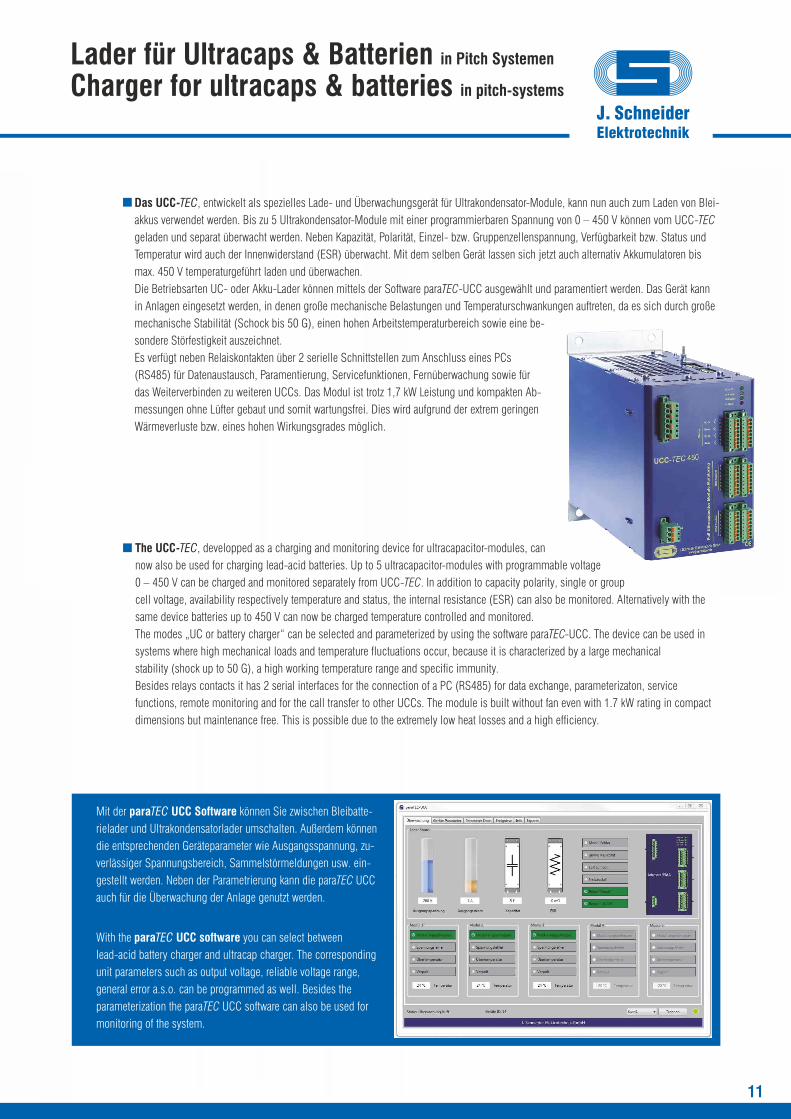
Das UCC-TEC, entwickelt als spezielles Lade- und Überwachungsgerät für Ultrakondensator-Module, kann nun auch zum Laden von Blei-
akkus verwendet werden. Bis zu 5 Ultrakondensator-Module mit einer programmierbaren Spannung von 0 – 450 V können vom UCC-TEC
geladen und separat überwacht werden. Neben Kapazität, Polarität, Einzel- bzw. Gruppenzellenspannung, Verfügbarkeit bzw. Status und
Temperatur wird auch der Innenwiderstand (ESR) überwacht. Mit dem selben Gerät lassen sich jetzt auch alternativ Akkumulatoren bis
max. 450 V temperaturgeführt laden und überwachen.
Die Betriebsarten UC- oder Akku-Lader können mittels der Software paraTEC-UCC ausgewählt und paramentiert werden. Das Gerät kann
in Anlagen eingesetzt werden, in denen große mechanische Belastungen und Temperaturschwankungen auftreten, da es sich durch große
mechanische Stabilität (Schock bis 50 G), einen hohen Arbeitstemperaturbereich sowie eine be-
sondere Störfestigkeit auszeichnet.
Es verfügt neben Relaiskontakten über 2 serielle Schnittstellen zum Anschluss eines PCs
(RS485) für Datenaustausch, Paramentierung, Servicefunktionen, Fernüberwachung sowie für
das Weiterverbinden zu weiteren UCCs. Das Modul ist trotz 1,7 kW Leistung und kompakten Ab-
messungen ohne Lüfter gebaut und somit wartungsfrei. Dies wird aufgrund der extrem geringen
Wärmeverluste bzw. eines hohen Wirkungsgrades möglich.
The UCC-TEC, developped as a charging and monitoring device for ultracapacitor-modules, can
now also be used for charging lead-acid batteries. Up to 5 ultracapacitor-modules with programmable voltage
0 – 450 V can be charged and monitored separately from UCC-TEC. In addition to capacity polarity, single or group
cell voltage, availability respectively temperature and status, the internal resistance (ESR) can also be monitored. Alternatively with the
same device batteries up to 450 V can now be charged temperature controlled and monitored.
The modes „UC or battery charger“ can be selected and parameterized by using the software paraTEC-UCC. The device can be used in
systems where high mechanical loads and temperature fluctuations occur, because it is characterized by a large mechanical
stability (shock up to 50 G), a high working temperature range and specific immunity.
Besides relays contacts it has 2 serial interfaces for the connection of a PC (RS485) for data exchange, parameterizaton, service
functions, remote monitoring and for the call transfer to other UCCs. The module is built without fan even with 1.7 kW rating in compact
dimensions but maintenance free. This is possible due to the extremely low heat losses and a high efficiency.
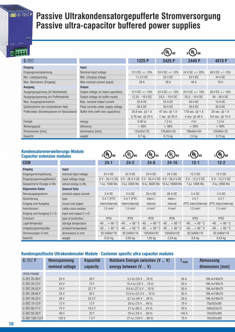
1225 P 2425 P 2440 P 4815 PC-TEC
Eingang
Eingangsnennspannung
Min. Ladespannung
Max. Nennstrom (Eingang)
Ausgang
Ausgangsspannung (im Netzbetrieb)
Ausgangsspannung (im Pufferbetrieb)
Max. Ausgangsnennstrom
Spitzenströme bei vorhandenem Netz
Pufferzeiten (Kondensatoren im Neuzustand)
Energie
Wirkungsgrad
Dimensionen [mm]
Gewicht
Input
Nominal Input voltage
Min. charging voltage
Max nominal current (input)
Output
Output voltage (in mains operation)
Output voltage (in buffer-mode)
Max. nominal output current
Peak currents under supply voltage
Buffer time (with new capacitors)
energy
efficiency
dimensions [mm]
weight
12 V DC +/- 10%
11,3 V DC
28 A
12 V DC +/- 10%
12,25 - 10 V DC
25 A DC
50 A DC
35,9 sec. @ 1 A
0,76 sec. @ 25 A
0,46 kJ
> 90%
125x65x135
0,7 kg
24 V DC +/- 10%
22 V DC
28 A
24 V DC +/- 10%
24,5 - 19 V DC
25 A DC
50 A DC
47 sec. @ 1 A
1 sec. @ 20 A
1,2 kJ
> 90%
125x65x135
0,75 kg
24 V DC +/- 20%
23 V DC
40 A
24 V DC +/- 10%
25,5 - 19 V DC
40 A DC
40 A DC
170 sec. @ 1 A
4 sec. @ 40 A
4 kJ
> 90%
188x84x194
2,0 kg
48 V DC +/- 10%
44 V DC
18 A
48 V DC +/- 10%
49 - 38 V DC
15 A DC
30 A DC
25 sec. @ 1 A
0,6 sec. @ 15 A
1,2 kJ
> 90%
125x65x135
0,75 kg
Kondensatorenerweiterungs-ModuleCapacitor extension modules
Mit der paraTEC UCC Software können Sie zwischen Bleibatte-
rielader und Ultrakondensatorlader umschalten. Außerdem können
die entsprechenden Geräteparameter wie Ausgangsspannung, zu-
verlässiger Spannungsbereich, Sammelstörmeldungen usw. ein-
gestellt werden. Neben der Parametrierung kann die paraTEC UCC
auch für die Überwachung der Anlage genutzt werden.
With the paraTEC UCC software you can select between
lead-acid battery charger and ultracap charger. The corresponding
unit parameters such as output voltage, reliable voltage range,
general error a.s.o. can be programmed as well. Besides the
parameterization the paraTEC UCC software can also be used for
monitoring of the system.
AC C-TECC-TEC F Nennspannung
nominal voltage
Kapazität
capacity
Nutzbare Energie zwischen (V ... V)
energy between (V ... V)
I max Abmessung
dimensions [mm]
OPEN FRAME
C-TEC 25-36 F
C-TEC 25-72 F
C-TEC 28-32 F
C-TEC 28-65 F
C-TEC 40-23 F
C-TEC 75-12 F
C-TEC 85-11 F
C-TEC 55-32 F
C-TEC 120-7,5 F
24 V
24 V
24 V
24 V
36 V
72 V
72 V
48 V
120 V
50 A
50 A
50 A
50 A
50 A
70 A
50 A
140 A
70 A
186,4x190x70
186,4x190x70
186,4x190x70
186,4x190x70
186,4x190x70
70x202x385
300x223x70
70x202x385
70x202x385
36 F
72 F
32,7 F
65 F
22,5 F
12 F
10,5 F
32 F
7,5 F
5,2 kJ (25 V ... 18 V)
10,4 kJ (25 V ... 18 V)
6,8 kJ (27,5 V ... 18 V)
13,5 kJ (27,5 V ... 18 V)
8,7 kJ (40 V ... 28 V)
20 kJ (75 V ... 48 V)
21 kJ (85 V ... 54 V)
25 kJ (55 V ... 38 V)
27 kJ (120 V ... 80 V)
Kundenspezifische Ultrakondensator Module · Customer specific ultra capacitor modules
10
11
Passive Ultrakondensatorgepufferte Stromversorgung Passive ultra-capacitor buffered power supplies
Lader für Ultracaps & Batterien in Pitch Systemen
Charger for ultracaps & batteries in pitch-systems
AC C-TEC 24-1CEM 24-2 24-8 24-16 12-1 12-2
Eingang
Eingangsnennspannung
Eingangsspannungsbereich
Gespeicherte Energie in Ws
Allgemeine Daten
Nennausgangsstrom
Absicherung
Eingang und Ausgang
Anschlussart
Eingang und Ausgang C+/C-
Schutzart
Lagertemperatur
Umgebungstemperatur
Abmessungen in mm
Gewicht
Input
nominal input voltage
input voltage range
stored energy in Ws
General Data
nominal output current
fuse
inrush and output
cable cross section
input and output C+/C-
type of protection
storage temperature
ambient temperature
dimensions in mm
weight
24 V DC
0 V - 26,4 V DC
1 kJ, 1000 Ws
3 A DC
3 A T (PTC
intern/internal)
1,5 mm²
IP20
-40 ... + 60 ° C
-40 ... + 60 ° C
92,5x60x116
0,52 kg
24 V DC
0 V - 26,4 V DC
2 kJ, 2000 Ws
3 A DC
3 A T (PTC
intern/internal)
1,5 mm²
IP20
-40 ... + 60 ° C
-40 ... + 60 ° C
92,5x60x116
0,65 kg
24 V DC
0 V - 26,4 V DC
8 kJ, 8000 Ws
20 A DC
intern /
internal
4 mm²
IP20
-40 ... + 60 ° C
-40 ... + 60 ° C
192x84x192
1,85 kg
24 V DC
0 V - 26,4 V DC
16 kJ, 16000 Ws
20 A DC
intern /
internal
4 mm²
IP20
-40 ... + 60 ° C
-40 ... + 60 ° C
192x84x192
2,54 kg
12 V DC
0 V - 13,2 V DC
1 kJ, 1000 Ws
3 A DC
3 A T
(PTC intern/internal)
1,5 mm²
IP20
-40 ... + 60 ° C
-40 ... + 60 ° C
92,5x60x116
0,6 kg
12 V DC
0 V - 13,2 V DC
2 kJ, 2000 Ws
3 A DC
3 A T
(PTC intern/internal)
1,5 mm²
IP20
-40 ... + 60 ° C
-40 ... + 60 ° C
92,5x60x116
0,63 kg
Das UCC-TEC, entwickelt als spezielles Lade- und Überwachungsgerät für Ultrakondensator-Module, kann nun auch zum Laden von Blei-
akkus verwendet werden. Bis zu 5 Ultrakondensator-Module mit einer programmierbaren Spannung von 0 – 450 V können vom UCC-TEC
geladen und separat überwacht werden. Neben Kapazität, Polarität, Einzel- bzw. Gruppenzellenspannung, Verfügbarkeit bzw. Status und
Temperatur wird auch der Innenwiderstand (ESR) überwacht. Mit dem selben Gerät lassen sich jetzt auch alternativ Akkumulatoren bis
max. 450 V temperaturgeführt laden und überwachen.
Die Betriebsarten UC- oder Akku-Lader können mittels der Software paraTEC-UCC ausgewählt und paramentiert werden. Das Gerät kann
in Anlagen eingesetzt werden, in denen große mechanische Belastungen und Temperaturschwankungen auftreten, da es sich durch große
mechanische Stabilität (Schock bis 50 G), einen hohen Arbeitstemperaturbereich sowie eine be-
sondere Störfestigkeit auszeichnet.
Es verfügt neben Relaiskontakten über 2 serielle Schnittstellen zum Anschluss eines PCs
(RS485) für Datenaustausch, Paramentierung, Servicefunktionen, Fernüberwachung sowie für
das Weiterverbinden zu weiteren UCCs. Das Modul ist trotz 1,7 kW Leistung und kompakten Ab-
messungen ohne Lüfter gebaut und somit wartungsfrei. Dies wird aufgrund der extrem geringen
Wärmeverluste bzw. eines hohen Wirkungsgrades möglich.
The UCC-TEC, developped as a charging and monitoring device for ultracapacitor-modules, can
now also be used for charging lead-acid batteries. Up to 5 ultracapacitor-modules with programmable voltage
0 – 450 V can be charged and monitored separately from UCC-TEC. In addition to capacity polarity, single or group
cell voltage, availability respectively temperature and status, the internal resistance (ESR) can also be monitored. Alternatively with the
same device batteries up to 450 V can now be charged temperature controlled and monitored.
The modes „UC or battery charger“ can be selected and parameterized by using the software paraTEC-UCC. The device can be used in
systems where high mechanical loads and temperature fluctuations occur, because it is characterized by a large mechanical
stability (shock up to 50 G), a high working temperature range and specific immunity.
Besides relays contacts it has 2 serial interfaces for the connection of a PC (RS485) for data exchange, parameterizaton, service
functions, remote monitoring and for the call transfer to other UCCs. The module is built without fan even with 1.7 kW rating in compact
dimensions but maintenance free. This is possible due to the extremely low heat losses and a high efficiency.
1225 P 2425 P 2440 P 4815 PC-TEC
Eingang
Eingangsnennspannung
Min. Ladespannung
Max. Nennstrom (Eingang)
Ausgang
Ausgangsspannung (im Netzbetrieb)
Ausgangsspannung (im Pufferbetrieb)
Max. Ausgangsnennstrom
Spitzenströme bei vorhandenem Netz
Pufferzeiten (Kondensatoren im Neuzustand)
Energie
Wirkungsgrad
Dimensionen [mm]
Gewicht
Input
Nominal Input voltage
Min. charging voltage
Max nominal current (input)
Output
Output voltage (in mains operation)
Output voltage (in buffer-mode)
Max. nominal output current
Peak currents under supply voltage
Buffer time (with new capacitors)
energy
efficiency
dimensions [mm]
weight
12 V DC +/- 10%
11,3 V DC
28 A
12 V DC +/- 10%
12,25 - 10 V DC
25 A DC
50 A DC
35,9 sec. @ 1 A
0,76 sec. @ 25 A
0,46 kJ
> 90%
125x65x135
0,7 kg
24 V DC +/- 10%
22 V DC
28 A
24 V DC +/- 10%
24,5 - 19 V DC
25 A DC
50 A DC
47 sec. @ 1 A
1 sec. @ 20 A
1,2 kJ
> 90%
125x65x135
0,75 kg
24 V DC +/- 20%
23 V DC
40 A
24 V DC +/- 10%
25,5 - 19 V DC
40 A DC
40 A DC
170 sec. @ 1 A
4 sec. @ 40 A
4 kJ
> 90%
188x84x194
2,0 kg
48 V DC +/- 10%
44 V DC
18 A
48 V DC +/- 10%
49 - 38 V DC
15 A DC
30 A DC
25 sec. @ 1 A
0,6 sec. @ 15 A
1,2 kJ
> 90%
125x65x135
0,75 kg
Kondensatorenerweiterungs-ModuleCapacitor extension modules
Mit der paraTEC UCC Software können Sie zwischen Bleibatte-
rielader und Ultrakondensatorlader umschalten. Außerdem können
die entsprechenden Geräteparameter wie Ausgangsspannung, zu-
verlässiger Spannungsbereich, Sammelstörmeldungen usw. ein-
gestellt werden. Neben der Parametrierung kann die paraTEC UCC
auch für die Überwachung der Anlage genutzt werden.
With the paraTEC UCC software you can select between
lead-acid battery charger and ultracap charger. The corresponding
unit parameters such as output voltage, reliable voltage range,
general error a.s.o. can be programmed as well. Besides the
parameterization the paraTEC UCC software can also be used for
monitoring of the system.
AC C-TECC-TEC F Nennspannung
nominal voltage
Kapazität
capacity
Nutzbare Energie zwischen (V ... V)
energy between (V ... V)
I max Abmessung
dimensions [mm]
OPEN FRAME
C-TEC 25-36 F
C-TEC 25-72 F
C-TEC 28-32 F
C-TEC 28-65 F
C-TEC 40-23 F
C-TEC 75-12 F
C-TEC 85-11 F
C-TEC 55-32 F
C-TEC 120-7,5 F
24 V
24 V
24 V
24 V
36 V
72 V
72 V
48 V
120 V
50 A
50 A
50 A
50 A
50 A
70 A
50 A
140 A
70 A
186,4x190x70
186,4x190x70
186,4x190x70
186,4x190x70
186,4x190x70
70x202x385
300x223x70
70x202x385
70x202x385
36 F
72 F
32,7 F
65 F
22,5 F
12 F
10,5 F
32 F
7,5 F
5,2 kJ (25 V ... 18 V)
10,4 kJ (25 V ... 18 V)
6,8 kJ (27,5 V ... 18 V)
13,5 kJ (27,5 V ... 18 V)
8,7 kJ (40 V ... 28 V)
20 kJ (75 V ... 48 V)
21 kJ (85 V ... 54 V)
25 kJ (55 V ... 38 V)
27 kJ (120 V ... 80 V)
Kundenspezifische Ultrakondensator Module · Customer specific ultra capacitor modules
10
12
Primärgetaktete NetzgerätePrimary switched power supplies
2410 N 2412 N 2424 N2405 N 2406 NUNOTEC N TRETEC N
Eingang
Eingangsspannungsbereich
Eingangsstrom
Einschaltstromstoß nach 1 ms
Ausgang
Ausgangsspannung
Power Boost
Wirkungsgrad
Schutzmaßnahme
Allgemeine Daten
MTBF
Netzausfallüberbrückung
Statusanzeige
Normen
Temperaturbereich
Befestigungsart
Abmessungen (HxWxD)
Sonstiges
Zulassungen
Gewicht
Eingang
Eingangsspannungsbereich
Eingangsstrom
Einschaltstromstoß nach 1 ms
Ausgang
Ausgangsspannung
Power Boost
Wirkungsgrad
Schutzmaßnahme
Allgemeine Daten
MTBF
Netzausfallüberbrückung
Statusanzeige
Normen
Temperaturbereich
Befestigungsart
Abmessungen (HxWxD)
Sonstiges
Zulassungen
Gewicht
Input
input voltage range
input current
inrush current after 1 ms
Output
output voltage
power boost
efficiency
protective system
General data
MTBF
ride through
status LED
standards
temperature range
installation
dimensions (hxwxd)
miscellaneous
approvals
weight
Input
input voltage range
input current
inrush current after 1 ms
Output
output voltage
power boost
efficiency
protective system
General data
MTBF
ride through
status LED
standards
temperature range
installation
dimensions (hxwxd)
miscellaneous
approvals
weight
einstellbar 24 ... 28 V DC / adjustable 24 ... 28 V DC
150% für 4 Sekunden / 150% for 4 seconds
bis zu 95% / up to 95%
kurzschluss- und überlastfest (Ausgang), Power Limiter /
short-circuit and overload protection (output), Power Limiter
> 500.000 h
> 20 ms bei 230 V AC / > 20 ms at 230 V AC
LED grün/rot / LED green/red
EN 60950-1, EN 61204-3, EN 55011 B, EN 61000-3-2
-25 ... +60° C ohne Derating (Lagertemperatur -40 ... +85° C)
-13 ... +140° F without derating (storage temperature -40 ... +185° F)
schnappbar auf Tragschiene TH 35 (EN 60715)
DIN-rail mountable TH 35 (EN60715)
Relais-Alarmkontakt für Kurzschluss, Überlast und Übertemperatur
relay alarm contact for short-circuit, overload and overtemperature
UL
einstellbar 24 ... 28 V DC / adjustable 24 ... 28 V DC
150% für 5 Sekunden / 150% for 5 seconds
bis zu 95% / up to 95%
kurzschluss- und überlastfest (Ausgang), Power Limiter /
short-circuit and overload protection (output), Power Limiter
> 1.000.000 h
> 25 ms bei 3 x 360 V AC / > 25 ms at 3 x 360 V AC
LED grün/rot / LED green/red
EN 60950-1, EN 61204-3, EN 55011 B, EN 61000-3-2
-25 ... +60° C ohne Derating (Lagertemperatur -40 ... +85° C)
-13 ... +140° F without derating (storage temperature -40 ... +185° F)
schnappbar auf Tragschiene TH 35 (EN 60715)
DIN-rail mountable TH 35 (EN60715)
Meldekontakt für Kurzschluss, Überlast und Übertemperatur
relay alarm contact for short-circuit, overload and overtemperature
UL
2420 N 2448 N
< 13 A < 9,5 A < 9 A < 13 A < 14 A
85 ... 265 V AC / 90 ... V DC 3 x 324...572 V AC / 450...745 V DC / 480...745 V DC
0,55 A bei 240 V AC 0,45 A bei/at 3 x 360 V AC 0,75 A bei/at 3 x 360 V AC 1,3 A bei/at 3 x 360 V AC 2,3 A bei/at 3 x 360 V AC
125x50x137 mm 123x65x143 mm123x50x143 mm
0,76 kg 0,76 kg0,66 kg1,3 kg 2,7 kg0,9 kg 1,2 kg
1,1 A bei 240 V AC
125x65x137 mm 123x65x167 mm
2,2 A bei 240 V AC
125x85x137 mm 138x109x182 mm
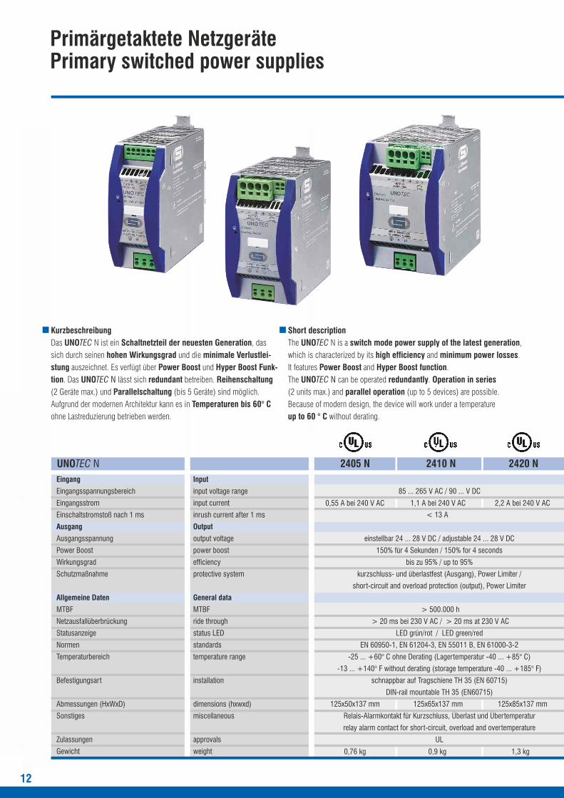
Kurzbeschreibung
Das UNOTEC N ist ein Schaltnetzteil der neuesten Generation, das
sich durch seinen hohen Wirkungsgrad und die minimale Verlustlei-
stung auszeichnet. Es verfügt über Power Boost und Hyper Boost Funk-
tion. Das UNOTEC N lässt sich redundant betreiben. Reihenschaltung
(2 Geräte max.) und Parallelschaltung (bis 5 Geräte) sind möglich.
Aufgrund der modernen Architektur kann es in Temperaturen bis 60° C
ohne Lastreduzierung betrieben werden.
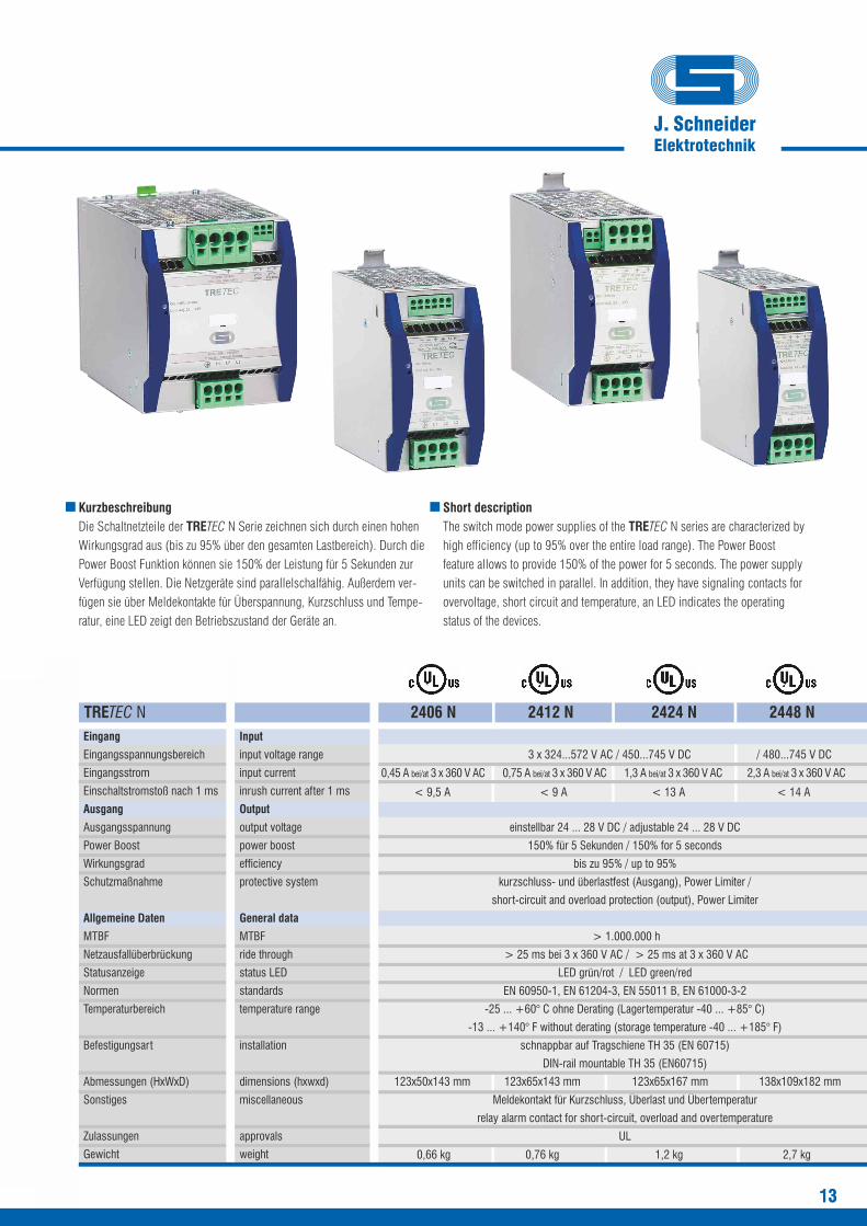
Kurzbeschreibung
Die Schaltnetzteile der TRETEC N Serie zeichnen sich durch einen hohen
Wirkungsgrad aus (bis zu 95% über den gesamten Lastbereich). Durch die
Power Boost Funktion können sie 150% der Leistung für 5 Sekunden zur
Verfügung stellen. Die Netzgeräte sind parallelschalfähig. Außerdem ver-
fügen sie über Meldekontakte für Überspannung, Kurzschluss und Tempe-
ratur, eine LED zeigt den Betriebszustand der Geräte an.
Short description
The UNOTEC N is a switch mode power supply of the latest generation,
which is characterized by its high efficiency and minimum power losses.
It features Power Boost and Hyper Boost function.
The UNOTEC N can be operated redundantly. Operation in series
(2 units max.) and parallel operation (up to 5 devices) are possible.
Because of modern design, the device will work under a temperature
up to 60 ° C without derating.
Short description
The switch mode power supplies of the TRETEC N series are characterized by
high efficiency (up to 95% over the entire load range). The Power Boost
feature allows to provide 150% of the power for 5 seconds. The power supply
units can be switched in parallel. In addition, they have signaling contacts for
overvoltage, short circuit and temperature, an LED indicates the operating
status of the devices.
1313
12
Primärgetaktete NetzgerätePrimary switched power supplies
2410 N 2412 N 2424 N2405 N 2406 NUNOTEC N TRETEC N
Eingang
Eingangsspannungsbereich
Eingangsstrom
Einschaltstromstoß nach 1 ms
Ausgang
Ausgangsspannung
Power Boost
Wirkungsgrad
Schutzmaßnahme
Allgemeine Daten
MTBF
Netzausfallüberbrückung
Statusanzeige
Normen
Temperaturbereich
Befestigungsart
Abmessungen (HxWxD)
Sonstiges
Zulassungen
Gewicht
Eingang
Eingangsspannungsbereich
Eingangsstrom
Einschaltstromstoß nach 1 ms
Ausgang
Ausgangsspannung
Power Boost
Wirkungsgrad
Schutzmaßnahme
Allgemeine Daten
MTBF
Netzausfallüberbrückung
Statusanzeige
Normen
Temperaturbereich
Befestigungsart
Abmessungen (HxWxD)
Sonstiges
Zulassungen
Gewicht
Input
input voltage range
input current
inrush current after 1 ms
Output
output voltage
power boost
efficiency
protective system
General data
MTBF
ride through
status LED
standards
temperature range
installation
dimensions (hxwxd)
miscellaneous
approvals
weight
Input
input voltage range
input current
inrush current after 1 ms
Output
output voltage
power boost
efficiency
protective system
General data
MTBF
ride through
status LED
standards
temperature range
installation
dimensions (hxwxd)
miscellaneous
approvals
weight
einstellbar 24 ... 28 V DC / adjustable 24 ... 28 V DC
150% für 4 Sekunden / 150% for 4 seconds
bis zu 95% / up to 95%
kurzschluss- und überlastfest (Ausgang), Power Limiter /
short-circuit and overload protection (output), Power Limiter
> 500.000 h
> 20 ms bei 230 V AC / > 20 ms at 230 V AC
LED grün/rot / LED green/red
EN 60950-1, EN 61204-3, EN 55011 B, EN 61000-3-2
-25 ... +60° C ohne Derating (Lagertemperatur -40 ... +85° C)
-13 ... +140° F without derating (storage temperature -40 ... +185° F)
schnappbar auf Tragschiene TH 35 (EN 60715)
DIN-rail mountable TH 35 (EN60715)
Relais-Alarmkontakt für Kurzschluss, Überlast und Übertemperatur
relay alarm contact for short-circuit, overload and overtemperature
UL
einstellbar 24 ... 28 V DC / adjustable 24 ... 28 V DC
150% für 5 Sekunden / 150% for 5 seconds
bis zu 95% / up to 95%
kurzschluss- und überlastfest (Ausgang), Power Limiter /
short-circuit and overload protection (output), Power Limiter
> 1.000.000 h
> 25 ms bei 3 x 360 V AC / > 25 ms at 3 x 360 V AC
LED grün/rot / LED green/red
EN 60950-1, EN 61204-3, EN 55011 B, EN 61000-3-2
-25 ... +60° C ohne Derating (Lagertemperatur -40 ... +85° C)
-13 ... +140° F without derating (storage temperature -40 ... +185° F)
schnappbar auf Tragschiene TH 35 (EN 60715)
DIN-rail mountable TH 35 (EN60715)
Meldekontakt für Kurzschluss, Überlast und Übertemperatur
relay alarm contact for short-circuit, overload and overtemperature
UL
2420 N 2448 N
< 13 A < 9,5 A < 9 A < 13 A < 14 A
85 ... 265 V AC / 90 ... V DC 3 x 324...572 V AC / 450...745 V DC / 480...745 V DC
0,55 A bei 240 V AC 0,45 A bei/at 3 x 360 V AC 0,75 A bei/at 3 x 360 V AC 1,3 A bei/at 3 x 360 V AC 2,3 A bei/at 3 x 360 V AC
125x50x137 mm 123x65x143 mm123x50x143 mm
0,76 kg 0,76 kg0,66 kg1,3 kg 2,7 kg0,9 kg 1,2 kg
1,1 A bei 240 V AC
125x65x137 mm 123x65x167 mm
2,2 A bei 240 V AC
125x85x137 mm 138x109x182 mm
Kurzbeschreibung
Das UNOTEC N ist ein Schaltnetzteil der neuesten Generation, das
sich durch seinen hohen Wirkungsgrad und die minimale Verlustlei-
stung auszeichnet. Es verfügt über Power Boost und Hyper Boost Funk-
tion. Das UNOTEC N lässt sich redundant betreiben. Reihenschaltung
(2 Geräte max.) und Parallelschaltung (bis 5 Geräte) sind möglich.
Aufgrund der modernen Architektur kann es in Temperaturen bis 60° C
ohne Lastreduzierung betrieben werden.
Kurzbeschreibung
Die Schaltnetzteile der TRETEC N Serie zeichnen sich durch einen hohen
Wirkungsgrad aus (bis zu 95% über den gesamten Lastbereich). Durch die
Power Boost Funktion können sie 150% der Leistung für 5 Sekunden zur
Verfügung stellen. Die Netzgeräte sind parallelschalfähig. Außerdem ver-
fügen sie über Meldekontakte für Überspannung, Kurzschluss und Tempe-
ratur, eine LED zeigt den Betriebszustand der Geräte an.
Short description
The UNOTEC N is a switch mode power supply of the latest generation,
which is characterized by its high efficiency and minimum power losses.
It features Power Boost and Hyper Boost function.
The UNOTEC N can be operated redundantly. Operation in series
(2 units max.) and parallel operation (up to 5 devices) are possible.
Because of modern design, the device will work under a temperature
up to 60 ° C without derating.
Short description
The switch mode power supplies of the TRETEC N series are characterized by
high efficiency (up to 95% over the entire load range). The Power Boost
feature allows to provide 150% of the power for 5 seconds. The power supply
units can be switched in parallel. In addition, they have signaling contacts for
overvoltage, short circuit and temperature, an LED indicates the operating
status of the devices.
1313
Schneider KombinationenSchneider-Combinations
AC C-TEC
UNOTEC 2405 / TRETEC 2406 + C-TEC 2403-1
UNOTEC 2405 / TRETEC 2406 + C-TEC 2405-5
UNOTEC 2410 / TRETEC 2412 + C-TEC 2403-1
UNOTEC 2410 / TRETEC 2412 + C-TEC 2405-5
UNOTEC 2410 / TRETEC 2412 + C-TEC 2408-20
UNOTEC 2410 / TRETEC 2412 + C-TEC 2410-1
UNOTEC 2420 / TRETEC 2424 + C-TEC 2403-1
UNOTEC 2420 / TRETEC 2424 + C-TEC 2405-5
UNOTEC 2420 / TRETEC 2424 + C-TEC 2408-20
UNOTEC 2420 / TRETEC 2424 + C-TEC 2410-1
2
0
7
5
2
0
17
15
12
10
3
5
3
5
8
10
3
5
8
10
1
5
1
5
20
1
1
5
20
1
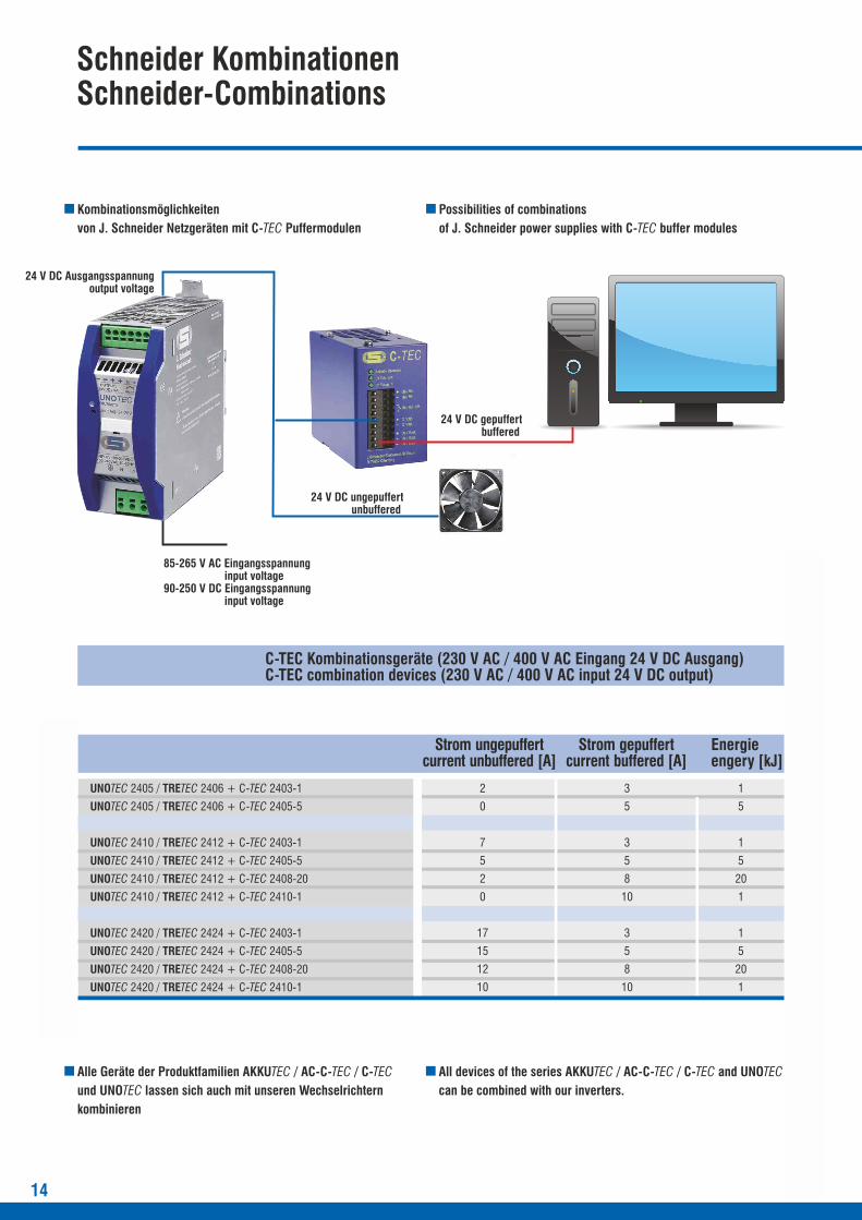
Kombinationsmöglichkeiten
von J. Schneider Netzgeräten mit C-TEC Puffermodulen
Possibilities of combinations
of J. Schneider power supplies with C-TEC buffer modules
C-TEC Kombinationsgeräte (230 V AC / 400 V AC Eingang 24 V DC Ausgang)C-TEC combination devices (230 V AC / 400 V AC input 24 V DC output)
Strom ungepuffertcurrent unbuffered [A]
Strom gepuffertcurrent buffered [A]
24 V DC ungepuffert unbuffered
24 V DC gepuffert buffered
24 V DC Ausgangsspannung output voltage
Energieengery [kJ]
15
Alle Geräte der Produktfamilien AKKUTEC / AC-C-TEC / C-TEC
und UNOTEC lassen sich auch mit unseren Wechselrichtern
kombinieren
All devices of the series AKKUTEC / AC-C-TEC / C-TEC and UNOTEC
can be combined with our inverters.
14
85-265 V AC Eingangsspannung input voltage90-250 V DC Eingangsspannung input voltage
DC-USV batteriegepuffertDC-UPS battery buffered
Projektierungstabelle · project engineering table
0,5 A
1A
2 A
5 A
10 A
15 A
20 A
40 A
80 A
AKKUTEC
2402 +
NBBH 2401
AKKUTEC
2402 +
NBBH 2401
AKKUTEC
2402 +
NBBH 2401
AKKUTEC
2405 +
NBBH 2401
AKKUTEC
2410 +
NBBH 2402
AKKUTEC
2420-07
AKKUTEC
2420-07
1xAKKUTEC
2440-0 +
NBBH2407HI
2xAKKUTEC
2440-0 +
NBBH 2417
AKKUTEC
2402 +
NBBH 2401
AKKUTEC
2402 +
NBBH 2401
AKKUTEC
2402 +
NBBH 2401
AKKUTEC
2405 +
NBBH 2402
AKKUTEC
2410-07
AKKUTEC
2420-07
AKKUTEC
2420-07
1xAKKUTEC
2440-0 +
NBBH 2417
2xAKKUTEC
2440-0 +
NBBH 2417
AKKUTEC
2402 +
NBBH 2401
AKKUTEC
2402 +
NBBH 2401
AKKUTEC
2402 +
NBBH 2401
AKKUTEC
2405 +
NBBH 2402
AKKUTEC
2410-07
AKKUTEC
2420-07
AKKUTEC
2420-12
1xAKKUTEC
2440-0 +
NBBH 2417
2xAKKUTEC
2440-0 +
NBBH 2440
AKKUTEC
2402 +
NBBH 2401
AKKUTEC
2402 +
NBBH 2401
AKKUTEC
2402 +
NBBH 2401
AKKUTEC
2405-07
AKKUTEC
2410-07
AKKUTEC
2420-12
AKKUTEC
2420-12
1xAKKUTEC
2440-0 +
NBBH 2417
2xAKKUTEC
2440-0 +
NBBH 2465
AKKUTEC
2402 +
NBBH 2401
AKKUTEC
2402 +
NBBH 2401
AKKUTEC
2402 +
NBBH 2402
AKKUTEC
2405-07
AKKUTEC
2410-12
AKKUTEC
2420-12
AKKUTEC
2420-0 +
NBBH 2417
1xAKKUTEC
2440-0 +
NBBH 2440
2xAKKUTEC
2440-0 +
2xSB 100-12
AKKUTEC
2402 +
NBBH 2401
AKKUTEC
2402 +
NBBH 2402
AKKUTEC
2402 +
NBBH 2407
AKKUTEC
2405-12
AKKUTEC
2410-0 +
NBBH 2417
AKKUTEC
2420-0 +
NBBH 2417
AKKUTEC
2420-0 +
NBBH 2440
1xAKKUTEC
2440-0 +
NBBH 2465
2xAKKUTEC
2440-0 +
2xSB 150-12
AKKUTEC
2402 +
NBBH 2402
AKKUTEC
2402 +
NBBH 2407
AKKUTEC
2403+
NBBH 2407
AKKUTEC
2410-0 +
NBBH 2417
AKKUTEC
2410-0 +
NBBH 2440
AKKUTEC
2420-0 +
NBBH 2465
AKKUTEC
2420-0 +
NBBH 2465
1xAKKUTEC
2440-0 +
2xSB 150-12
2xAKKUTEC
2440-0 +
4xSB 150-12
AKKUTEC
2402 +
NBBH 2402
AKKUTEC
2402 +
NBBH 2407
AKKUTEC
2403 +
NBBH 2412
AKKUTEC
2410-0 +
NBBH 2417
AKKUTEC
2420-0 +
NBBH 2465
AKKUTEC
2420-0 +
2xSB 100-12
1xAKKUTEC
2440-0 +
2xSB 100-12
1xAKKUTEC
2440-0 +
4xSB 100-12
2xAKKUTEC
2440-0 +
4xSB 200-12
AKKUTEC
2402 +
NBBH 2407
AKKUTEC
2402 +
NBBH 2412
AKKUTEC
2405-0
NBBH 2417
AKKUTEC
2410-0 +
NBBH 2465
AKKUTEC
2420-0 +
2x SB 100-12
1xAKKUTEC
2440-0 +
2xSB 150-12
1xAKKUTEC
2440-0 +
4xSB 100-12
2xAKKUTEC
2440-0 +
4xSB 200-12
AKKUTEC
2402 +
NBBH 2412
AKKUTEC
2403 +
NBBH 2417
AKKUTEC
2405-0
NBBH 2440
AKKUTEC
2420-0 +
2x SB 100-12
2 x AKKUTEC
2420-0 +
4x SB 100-12
1xAKKUTEC
2440-0 +
4xSB 150-12
Mit Hilfe der Projektierungstabelle finden Sie
leicht das richtige Gerät für Ihre Anwendung. Die
Daten beziehen sich auf eine Wiederaufladezeit
von ca. 10 h nach vollständiger Entladung und
gleichzeitiger Last von 100 %.
Andere Ströme bzw. Zeiten auf Anfrage
With the help of the project engineering
table you can find the correct equipment for
your application easily. The data consider of a
recharge time of approx. 10 hours after complete
discharge and 100 % load at the same time.
Other currents and times on request
StromCurrent
Zeit / time2 min
5 min
15 min
30 min
1 h
3 h
5 h
10 h
20 h
10 min
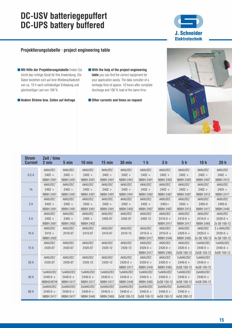
Schneider KombinationenSchneider-Combinations
AC C-TEC
UNOTEC 2405 / TRETEC 2406 + C-TEC 2403-1
UNOTEC 2405 / TRETEC 2406 + C-TEC 2405-5
UNOTEC 2410 / TRETEC 2412 + C-TEC 2403-1
UNOTEC 2410 / TRETEC 2412 + C-TEC 2405-5
UNOTEC 2410 / TRETEC 2412 + C-TEC 2408-20
UNOTEC 2410 / TRETEC 2412 + C-TEC 2410-1
UNOTEC 2420 / TRETEC 2424 + C-TEC 2403-1
UNOTEC 2420 / TRETEC 2424 + C-TEC 2405-5
UNOTEC 2420 / TRETEC 2424 + C-TEC 2408-20
UNOTEC 2420 / TRETEC 2424 + C-TEC 2410-1
2
0
7
5
2
0
17
15
12
10
3
5
3
5
8
10
3
5
8
10
1
5
1
5
20
1
1
5
20
1
Kombinationsmöglichkeiten
von J. Schneider Netzgeräten mit C-TEC Puffermodulen
Possibilities of combinations
of J. Schneider power supplies with C-TEC buffer modules
C-TEC Kombinationsgeräte (230 V AC / 400 V AC Eingang 24 V DC Ausgang)C-TEC combination devices (230 V AC / 400 V AC input 24 V DC output)
Strom ungepuffertcurrent unbuffered [A]
Strom gepuffertcurrent buffered [A]
24 V DC ungepuffert unbuffered
24 V DC gepuffert buffered
24 V DC Ausgangsspannung output voltage
Energieengery [kJ]
15
Alle Geräte der Produktfamilien AKKUTEC / AC-C-TEC / C-TEC
und UNOTEC lassen sich auch mit unseren Wechselrichtern
kombinieren
All devices of the series AKKUTEC / AC-C-TEC / C-TEC and UNOTEC
can be combined with our inverters.
14
85-265 V AC Eingangsspannung input voltage90-250 V DC Eingangsspannung input voltage
DC-USV batteriegepuffertDC-UPS battery buffered
Projektierungstabelle · project engineering table
0,5 A
1A
2 A
5 A
10 A
15 A
20 A
40 A
80 A
AKKUTEC
2402 +
NBBH 2401
AKKUTEC
2402 +
NBBH 2401
AKKUTEC
2402 +
NBBH 2401
AKKUTEC
2405 +
NBBH 2401
AKKUTEC
2410 +
NBBH 2402
AKKUTEC
2420-07
AKKUTEC
2420-07
1xAKKUTEC
2440-0 +
NBBH2407HI
2xAKKUTEC
2440-0 +
NBBH 2417
AKKUTEC
2402 +
NBBH 2401
AKKUTEC
2402 +
NBBH 2401
AKKUTEC
2402 +
NBBH 2401
AKKUTEC
2405 +
NBBH 2402
AKKUTEC
2410-07
AKKUTEC
2420-07
AKKUTEC
2420-07
1xAKKUTEC
2440-0 +
NBBH 2417
2xAKKUTEC
2440-0 +
NBBH 2417
AKKUTEC
2402 +
NBBH 2401
AKKUTEC
2402 +
NBBH 2401
AKKUTEC
2402 +
NBBH 2401
AKKUTEC
2405 +
NBBH 2402
AKKUTEC
2410-07
AKKUTEC
2420-07
AKKUTEC
2420-12
1xAKKUTEC
2440-0 +
NBBH 2417
2xAKKUTEC
2440-0 +
NBBH 2440
AKKUTEC
2402 +
NBBH 2401
AKKUTEC
2402 +
NBBH 2401
AKKUTEC
2402 +
NBBH 2401
AKKUTEC
2405-07
AKKUTEC
2410-07
AKKUTEC
2420-12
AKKUTEC
2420-12
1xAKKUTEC
2440-0 +
NBBH 2417
2xAKKUTEC
2440-0 +
NBBH 2465
AKKUTEC
2402 +
NBBH 2401
AKKUTEC
2402 +
NBBH 2401
AKKUTEC
2402 +
NBBH 2402
AKKUTEC
2405-07
AKKUTEC
2410-12
AKKUTEC
2420-12
AKKUTEC
2420-0 +
NBBH 2417
1xAKKUTEC
2440-0 +
NBBH 2440
2xAKKUTEC
2440-0 +
2xSB 100-12
AKKUTEC
2402 +
NBBH 2401
AKKUTEC
2402 +
NBBH 2402
AKKUTEC
2402 +
NBBH 2407
AKKUTEC
2405-12
AKKUTEC
2410-0 +
NBBH 2417
AKKUTEC
2420-0 +
NBBH 2417
AKKUTEC
2420-0 +
NBBH 2440
1xAKKUTEC
2440-0 +
NBBH 2465
2xAKKUTEC
2440-0 +
2xSB 150-12
AKKUTEC
2402 +
NBBH 2402
AKKUTEC
2402 +
NBBH 2407
AKKUTEC
2403+
NBBH 2407
AKKUTEC
2410-0 +
NBBH 2417
AKKUTEC
2410-0 +
NBBH 2440
AKKUTEC
2420-0 +
NBBH 2465
AKKUTEC
2420-0 +
NBBH 2465
1xAKKUTEC
2440-0 +
2xSB 150-12
2xAKKUTEC
2440-0 +
4xSB 150-12
AKKUTEC
2402 +
NBBH 2402
AKKUTEC
2402 +
NBBH 2407
AKKUTEC
2403 +
NBBH 2412
AKKUTEC
2410-0 +
NBBH 2417
AKKUTEC
2420-0 +
NBBH 2465
AKKUTEC
2420-0 +
2xSB 100-12
1xAKKUTEC
2440-0 +
2xSB 100-12
1xAKKUTEC
2440-0 +
4xSB 100-12
2xAKKUTEC
2440-0 +
4xSB 200-12
AKKUTEC
2402 +
NBBH 2407
AKKUTEC
2402 +
NBBH 2412
AKKUTEC
2405-0
NBBH 2417
AKKUTEC
2410-0 +
NBBH 2465
AKKUTEC
2420-0 +
2x SB 100-12
1xAKKUTEC
2440-0 +
2xSB 150-12
1xAKKUTEC
2440-0 +
4xSB 100-12
2xAKKUTEC
2440-0 +
4xSB 200-12
AKKUTEC
2402 +
NBBH 2412
AKKUTEC
2403 +
NBBH 2417
AKKUTEC
2405-0
NBBH 2440
AKKUTEC
2420-0 +
2x SB 100-12
2 x AKKUTEC
2420-0 +
4x SB 100-12
1xAKKUTEC
2440-0 +
4xSB 150-12
Mit Hilfe der Projektierungstabelle finden Sie
leicht das richtige Gerät für Ihre Anwendung. Die
Daten beziehen sich auf eine Wiederaufladezeit
von ca. 10 h nach vollständiger Entladung und
gleichzeitiger Last von 100 %.
Andere Ströme bzw. Zeiten auf Anfrage
With the help of the project engineering
table you can find the correct equipment for
your application easily. The data consider of a
recharge time of approx. 10 hours after complete
discharge and 100 % load at the same time.
Other currents and times on request
StromCurrent
Zeit / time2 min
5 min
15 min
30 min
1 h
3 h
5 h
10 h
20 h
10 min
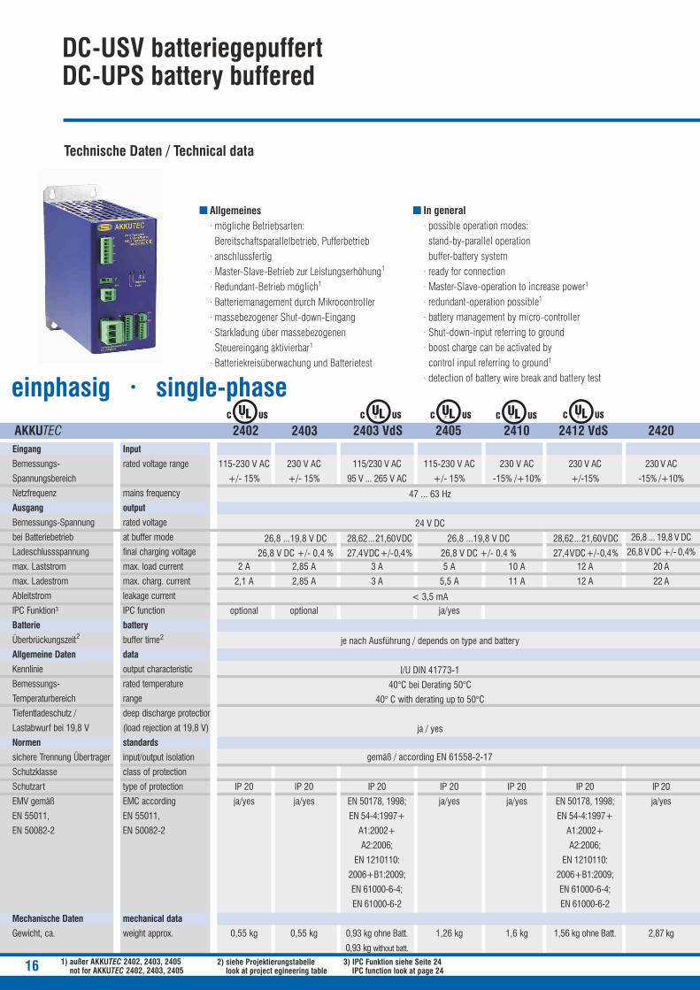
16 17
Technische Daten / Technical data
47 ... 63 Hz
24 V DC
< 3,5 mA
je nach Ausführung / depends on type and battery
I/U DIN 41773-1
40°C bei Derating 50°C
40° C with derating up to 50°C
ja / yes
Input
rated voltage range
mains frequency
output
rated voltage
at buffer mode
final charging voltage
max. load current
max. charg. current
leakage current
IPC function
battery 2buffer time
data
output characteristic
rated temperature
range
deep discharge protection
(load rejection at 19,8 V)
standards
input/output isolation
class of protection
type of protection
EMC according
EN 55011,
EN 50082-2
mechanical data
weight approx.
Eingang
Bemessungs-
Spannungsbereich
Netzfrequenz
Ausgang
Bemessungs-Spannung
bei Batteriebetrieb
Ladeschlussspannung
max. Laststrom
max. Ladestrom
Ableitstrom
IPC Funktion³
Batterie2Überbrückungszeit
Allgemeine Daten
Kennlinie
Bemessungs-
Temperaturbereich
Tiefentladeschutz /
Lastabwurf bei 19,8 V
Normen
sichere Trennung Übertrager
Schutzklasse
Schutzart
EMV gemäß
EN 55011,
EN 50082-2
Mechanische Daten
Gewicht, ca.
115-230 V AC
+/- 15%
2 A
2,1 A
optional
IP 20
ja/yes
0,55 kg
115-230 V AC
+/- 15%
5 A
5,5 A
ja/yes
IP 20
ja/yes
1,26 kg
230 V AC
-15% /+10%
10 A
11 A
IP 20
ja/yes
1,6 kg
230 V AC
-15% /+10%
26,8 ... 19,8 V DC
26,8 V DC +/- 0,4%
20 A
22 A
IP 20
ja/yes
2,87 kg
Allgemeines
· mögliche Betriebsarten:
Bereitschaftsparallelbetrieb, Pufferbetrieb
· anschlussfertig1· Master-Slave-Betrieb zur Leistungserhöhung
1· Redundant-Betrieb möglich
· Batteriemanagement durch Mikrocontroller
· massebezogener Shut-down-Eingang
· Starkladung über massebezogenen1 Steuereingang aktivierbar
· Batteriekreisüberwachung und Batterietest
Allgemeines
· Potentialfreier Meldeausgang und LED:
- Netzbetrieb
- für Sammelstörmeldung
- Batterieüberwachungsfenster für 1 Batteriespannung innerhalb/oberhalb
· Batterieverpolschutz1· Display-Panel-Anschluss
In general
· possible operation modes:
stand-by-parallel operation
buffer-battery system
· ready for connection1· Master-Slave-operation to increase power
1· redundant-operation possible
· battery management by micro-controller
· Shut-down-input referring to ground
· boost charge can be activated by1 control input referring to ground
· detection of battery wire break and battery test
In general
· potentialfree control contact and LED:
- for mains operation
- for general error
- battery voltage control window for voltage
within/above1
· protection against wrong battery polarization1· Display-Panel-connection
1) außer AKKUTEC 2402, 2403, 2405 not for AKKUTEC 2402, 2403, 2405
2) siehe Projektierungstabelle look at project egineering table
3) IPC Funktion siehe Seite 24 IPC function look at page 24
24402420AKKUTEC
45 ... 65 Hz
24 V DC
26,8...19,8 V DC
26,8 V +/- 0,4 %
< 3,5 mA
ja / yes
I
IP20
ja / yes
3 x 400 - 500 V AC
- 15 % + 10 %
3 x 400 - 500 V AC
+/- 10 %
Input
rated voltage range
mains frequency
output
rated voltage
at battery mode
final charging voltage
max. load current
max. charg. current
leakage current
battery 2buffer time
data
output characteristic
rated temperature range
battery
deep discharge protection
(load shadding at 19,8 V)
standards
input/output isolation
class of protection
type of protection
EMC according EN 55011, EN 50082-2
mechanical data
weight approx.
Eingang
Bemessungs-Spannungsbereich
Netzfrequenz
Ausgang
Bemessungs-Spannung
bei Batteriebetrieb
Ladeschlussspannung
max. Laststrom
max. Ladestrom
Ableitstrom
Batterie2Überbrückungszeit
Allgemeine Daten
Kennlinie
Bemessungs-Temperaturbereich
Batterie
Tiefentladeschutz /
Lastabwurf bei 19,8 V
Normen
sichere Trennung Übertrager
Schutzklasse
Schutzart
EMV gemäß EN 55011, EN 50082-2
Mechanische Daten
Gewicht, ca.
20 A
22 A
2,54 kg
40 A
44 A
3,6 kg
dreiphasig · three-phase
gemäß / according EN 61558-2-17
115/230 V AC
95 V ... 265 V AC
3 A
3 A
IP 20
EN 50178, 1998;
EN 54-4:1997+
A1:2002+
A2:2006;
EN 1210110:
2006+B1:2009;
EN 61000-6-4;
EN 61000-6-2
0,93 kg ohne Batt.
0,93 kg without batt.
2403 VdS2402 2403 24102405 2412 VdS 2420AKKUTEC
einphasig · single-phase
230 V AC
+/-15%
12 A
12 A
IP 20
EN 50178, 1998;
EN 54-4:1997+
A1:2002+
A2:2006;
EN 1210110:
2006+B1:2009;
EN 61000-6-4;
EN 61000-6-2
1,56 kg ohne Batt.
DC-USV batteriegepuffertDC-UPS battery buffered
26,8 ...19,8 V DC
26,8 V DC +/- 0,4 %
26,8 ...19,8 V DC
26,8 V DC +/- 0,4 %
28,62 ... 21,60 V DC
27,4 V DC +/- 0,4 %
28,62 ... 21,60 V DC
27,4 V DC +/- 0,4 %
230 V AC
+/- 15%
2,85 A
2,85 A
optional
IP 20
ja/yes
0,55 kg
je nach Ausführung / depends on type and battery
I/U DIN 41773-1
40°C bei Derating 50°C / 40° C with derating up to 50°C
20°C
gemäß / according EN 61558-2-17
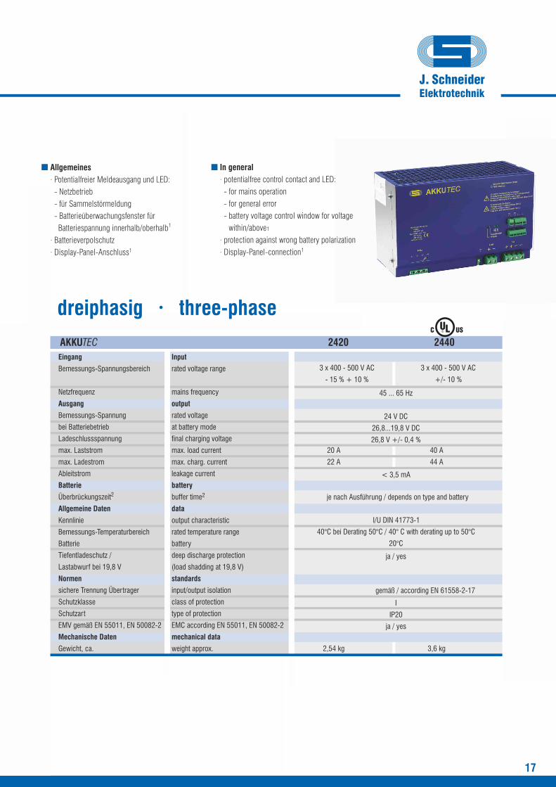
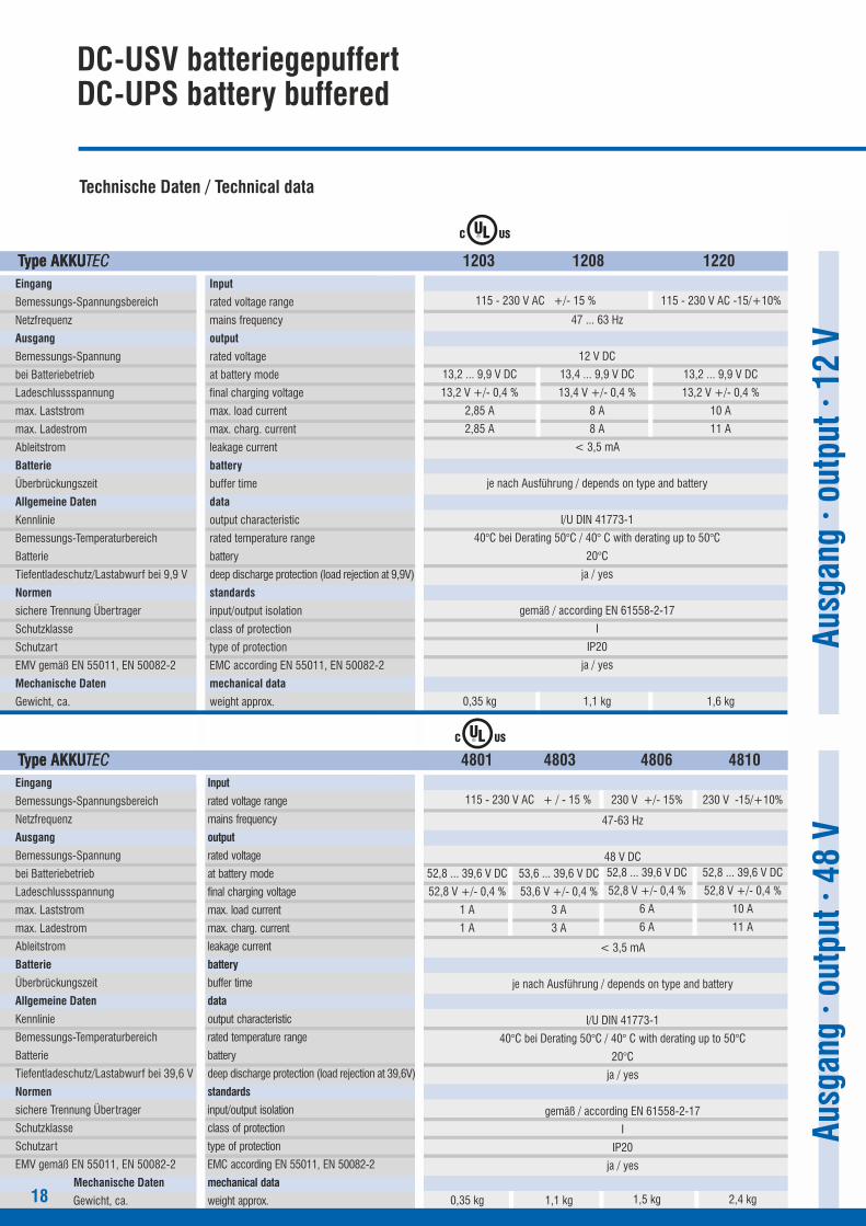
19
AKKUTEC im GehäuseAKKUTEC in cabinet
Technische Daten / Technical data
1208 12201203Type AKKUTECType AKKUTEC
47 ... 63 Hz
12 V DC
13,4 ... 9,9 V DC
13,4 V +/- 0,4 %
8 A
8 A
< 3,5 mA
je nach Ausführung / depends on type and battery
I/U DIN 41773-1
40°C bei Derating 50°C / 40° C with derating up to 50°C
20°C
ja / yes
gemäß / according EN 61558-2-17
I
IP20
ja / yes
1,1 kg
53,6 ... 39,6 V DC
53,6 V +/- 0,4 %
3 A
3 A
1,1 kg
13,2 ... 9,9 V DC
13,2 V +/- 0,4 %
2,85 A
2,85 A
0,35 kg
52,8 ... 39,6 V DC
52,8 V +/- 0,4 %
1 A
1 A
0,35 kg
13,2 ... 9,9 V DC
13,2 V +/- 0,4 %
10 A
11 A
1,6 kg
230 V -15/+10%
52,8 ... 39,6 V DC
52,8 V +/- 0,4 %
10 A
11 A
2,4 kg
230 V +/- 15%
52,8 ... 39,6 V DC
52,8 V +/- 0,4 %
6 A
6 A
1,5 kg
115 - 230 V AC +/- 15 % 115 - 230 V AC -15/+10%
115 - 230 V AC + / - 15 %
Input
rated voltage range
mains frequency
output
rated voltage
at battery mode
final charging voltage
max. load current
max. charg. current
leakage current
battery
buffer time
data
output characteristic
rated temperature range
battery
deep discharge protection (load rejection at 9,9V)
standards
input/output isolation
class of protection
type of protection
EMC according EN 55011, EN 50082-2
mechanical data
weight approx.
Eingang
Bemessungs-Spannungsbereich
Netzfrequenz
Ausgang
Bemessungs-Spannung
bei Batteriebetrieb
Ladeschlussspannung
max. Laststrom
max. Ladestrom
Ableitstrom
Batterie
Überbrückungszeit
Allgemeine Daten
Kennlinie
Bemessungs-Temperaturbereich
Batterie
Tiefentladeschutz/Lastabwurf bei 9,9 V
Normen
sichere Trennung Übertrager
Schutzklasse
Schutzart
EMV gemäß EN 55011, EN 50082-2
Mechanische Daten
Gewicht, ca.
Eingang
Bemessungs-Spannungsbereich
Netzfrequenz
Ausgang
Bemessungs-Spannung
bei Batteriebetrieb
Ladeschlussspannung
max. Laststrom
max. Ladestrom
Ableitstrom
Batterie
Überbrückungszeit
Allgemeine Daten
Kennlinie
Bemessungs-Temperaturbereich
Batterie
Tiefentladeschutz/Lastabwurf bei 39,6 V
Normen
sichere Trennung Übertrager
Schutzklasse
Schutzart
EMV gemäß EN 55011, EN 50082-2
Mechanische Daten
Gewicht, ca.
4803 4806 48104801Type AKKUTECType AKKUTEC
Aus
gang
· ou
tput
· 12
VA
usga
ng ·
outp
ut ·
48 V
18
DC-USV batteriegepuffertDC-UPS battery buffered
Abmessungen dimensions
AKKUTEC 2420
AKKUTEC 2410AKKUTEC 2405 USB
AKKUTEC 2402 AKKUTEC 19-2403
AKKUTEC 19-2420
AKKUTEC 2440
AKKUTEC 2420-12
AKKUTEC 2410-12
AKKUTEC
Netz
Error
Unterhalb
Oberhalb
128,4
55,0
3HE
11TE
47-63 Hz
48 V DC
< 3,5 mA
je nach Ausführung / depends on type and battery
I/U DIN 41773-1
40°C bei Derating 50°C / 40° C with derating up to 50°C
20°C
ja / yes
gemäß / according EN 61558-2-17
I
IP20
ja / yes
Input
rated voltage range
mains frequency
output
rated voltage
at battery mode
final charging voltage
max. load current
max. charg. current
leakage current
battery
buffer time
data
output characteristic
rated temperature range
battery
deep discharge protection (load rejection at 39,6V)
standards
input/output isolation
class of protection
type of protection
EMC according EN 55011, EN 50082-2
mechanical data
weight approx.
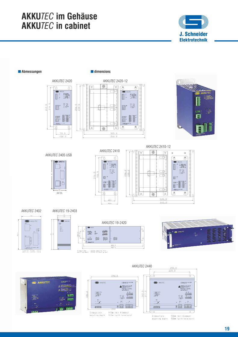
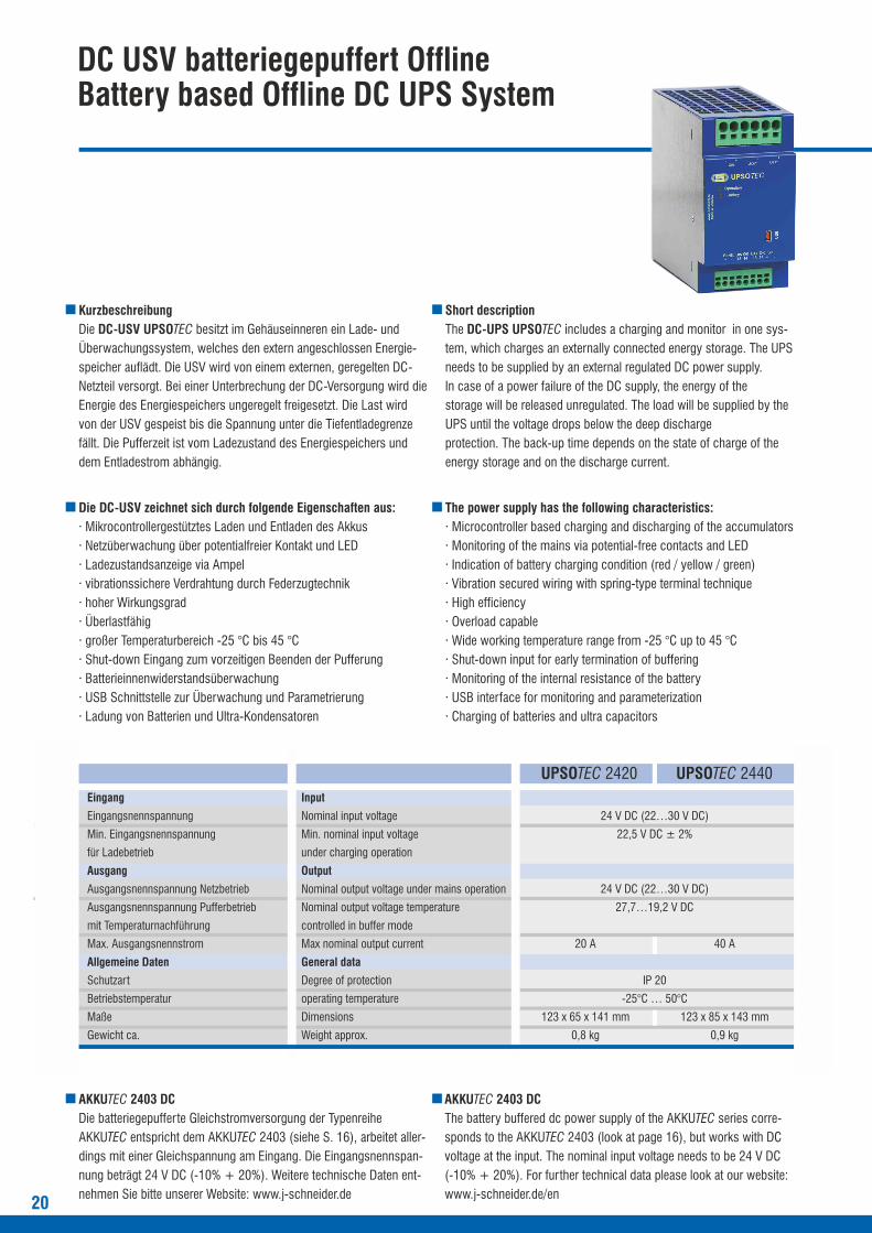
DC USV batteriegepuffert OfflineBattery based Offline DC UPS System
Lader für BatterienCharger for batteries
UPSOTEC 2420 UPSOTEC 2440
Bezeichnungdesignation
Anzahl Blöcke number of blocks
à 12 V
Spannungvoltage
bei/at 0° C
Spannungvoltage
bei/at 30° C
UNennUNom
(Batt.-System)
Eingang
Eingangsnennspannung
Min. Eingangsnennspannung
für Ladebetrieb
Ausgang
Ausgangsnennspannung Netzbetrieb
Ausgangsnennspannung Pufferbetrieb
mit Temperaturnachführung
Max. Ausgangsnennstrom
Allgemeine Daten
Schutzart
Betriebstemperatur
Maße
Gewicht ca. AKKUTEC SVC 450
AKKUTEC SVC 366
AKKUTEC SVC 220
AKKUTEC SVC 110
AKKUTEC SVC 72
AKKUTEC SVC 60
Input
Nominal input voltage
Min. nominal input voltage
under charging operation
Output
Nominal output voltage under mains operation
Nominal output voltage temperature
controlled in buffer mode
Max nominal output current
General data
Degree of protection
operating temperature
Dimensions
Weight approx. 32
26
18
9
6
5
384 V
312 V
216 V
108 V
72 V
60 V
450 V
366 V
254 V
126 V
84 V
70 V
434 V
352 V
244 V
122 V
80 V
68 V
24 V DC (22…30 V DC)
22,5 V DC ± 2%
24 V DC (22…30 V DC)
27,7…19,2 V DC
IP 20
-25°C … 50°C
20 A
123 x 65 x 141 mm
0,8 kg
40 A
123 x 85 x 143 mm
0,9 kg
Kurzbeschreibung
Die DC-USV UPSOTEC besitzt im Gehäuseinneren ein Lade- und
Überwachungssystem, welches den extern angeschlossen Energie-
speicher auflädt. Die USV wird von einem externen, geregelten DC-
Netzteil versorgt. Bei einer Unterbrechung der DC-Versorgung wird die
Energie des Energiespeichers ungeregelt freigesetzt. Die Last wird
von der USV gespeist bis die Spannung unter die Tiefentladegrenze
fällt. Die Pufferzeit ist vom Ladezustand des Energiespeichers und
dem Entladestrom abhängig.
AKKUTEC SVC
Das AKKUTEC SVC (Special Voltage Charger) ist ein Ladegerät für
Bleiakkumulatoren, das über mehrere Anschlussvarianten verfügt. Ma-
ximal können 32 Stück von 12 Volt Blöcken angeschlossen werden,
diese ergeben eine Gesamtspannung von 450 Volt (bei 0°C). Als Mini-
mum sind 5 Blöcke mit einer Gesamtspannung von 60 Volt vordefi-
niert. Weitere Varianten sind in untenstehender Tabelle aufgelistet. Die
Ladung erfolgt temperaturgeführt. Die PC Software paraTEC-UCC er-
möglicht die Einstellung auf eine beliebige Anzahl an Akkumulatoren.
Das Gerät kann in Anlagen eingesetzt werden, in denen große mecha-
nische Belastungen und Temperaturschwankungen auftreten. Da es
Bestandteil des Sicherheitskonzeptes der Anlagen ist, verfügt es über
zusätzliche Sicherheitssysteme und Diagnosemöglichkeiten.
Mit der PC Software paraTEC-UCC ist es, möglich den Lader zu
parametrieren und im Betrieb zu überwachen. Desweitern ermöglicht
die Wahl der Betriebsart eine Umstellung vom AKKUTEC SVC auf das
UCC-TEC.
AKKUTEC SVC
The AKKUTEC SVC (Special Voltage
Charger) is a charging unit for lead-
acidaccumulators, which has several
connection possibilities. Maximum 32 pieces of 12 Volt
blocks, which have a total voltage of 450 Volt (at 0°C) can be con-
nected . 5 blocks with a total voltage of 60 Volt are pre-defined as a
minimum. Other versions are specified in the table below. Charging of
the batteries will be temperature controlled. The PC software
paraTEC-UCC enables the adjustment of any number of accumula-
tors. The unit can be used in systems, in which high mechanical
stress and temperature variations are available. Because it is part of a
safety concept of the systems, it has additional safety systems and
analysis possibilities. With the PC software paraTEC-UCC it is possi-
ble to change parameters and to monitor the system. With the selec-
tion of the operational mode it is possible to switch over from
AKKUTEC SVC to UCC-TEC mode.
The back-up time depends on the state of charge of the accumulators
and of the discharge current.
Die DC-USV zeichnet sich durch folgende Eigenschaften aus:
· Mikrocontrollergestütztes Laden und Entladen des Akkus
· Netzüberwachung über potentialfreier Kontakt und LED
· Ladezustandsanzeige via Ampel
· vibrationssichere Verdrahtung durch Federzugtechnik
· hoher Wirkungsgrad
· Überlastfähig
· großer Temperaturbereich -25 °C bis 45 °C
· Shut-down Eingang zum vorzeitigen Beenden der Pufferung
· Batterieinnenwiderstandsüberwachung
· USB Schnittstelle zur Überwachung und Parametrierung
· Ladung von Batterien und Ultra-Kondensatoren
Das AKKUTEC SVC verfügt über folgende Merkmale:
· Große mechanische Stabilität
· Großer Arbeitstemperaturbereich
· serielle Schnittstellenanschlüsse für den Anschluss eines PCs
(RS485) (für Datenaustausch, Parametrierung, Servicefunktionen,
Fernüberwachung etc.) und für das Weiterverbinden zu weiteren
AKKUTECs
· Besondere Störfestigkeit
· Einbindung in SPS via RS485 bzw. Meldekontakte möglich
· Batterieüberwachung
· Potentialfreie Relaismeldekontakte
· Potentialfreie Open-Kollektor-Meldeausgänge
AKKUTEC 2403 DC
Die batteriegepufferte Gleichstromversorgung der Typenreihe
AKKUTEC entspricht dem AKKUTEC 2403 (siehe S. 16), arbeitet aller-
dings mit einer Gleichspannung am Eingang. Die Eingangsnennspan-
nung beträgt 24 V DC (-10% + 20%). Weitere technische Daten ent-
nehmen Sie bitte unserer Website: www.j-schneider.de
AKKUTEC 2403 DC
The battery buffered dc power supply of the AKKUTEC series corre-
sponds to the AKKUTEC 2403 (look at page 16), but works with DC
voltage at the input. The nominal input voltage needs to be 24 V DC
(-10% + 20%). For further technical data please look at our website:
www.j-schneider.de/en
Short description
The DC-UPS UPSOTEC includes a charging and monitor in one sys-
tem, which charges an externally connected energy storage. The UPS
needs to be supplied by an external regulated DC power supply.
In case of a power failure of the DC supply, the energy of the
storage will be released unregulated. The load will be supplied by the
UPS until the voltage drops below the deep discharge
protection. The back-up time depends on the state of charge of the
energy storage and on the discharge current.
The power supply has the following characteristics:
· Microcontroller based charging and discharging of the accumulators
· Monitoring of the mains via potential-free contacts and LED
· Indication of battery charging condition (red / yellow / green)
· Vibration secured wiring with spring-type terminal technique
· High efficiency
· Overload capable
· Wide working temperature range from -25 °C up to 45 °C
· Shut-down input for early termination of buffering
· Monitoring of the internal resistance of the battery
· USB interface for monitoring and parameterization
· Charging of batteries and ultra capacitors
The AKKUTEC SVC has the following features:
· high mechanical stability
· high operation temperature range
· serial interfaces for the communication with PC (RS485) (for data
transfer, parameterization, service functions, monitoring, …)
and for the connection to further AKKUTECs
· Special noise immunity
· integration in SPS via RS485 respectively message contacts
possible
· battery monitoring
· Potential-free contacts
· Potential-free open-collector-message outputs
2120
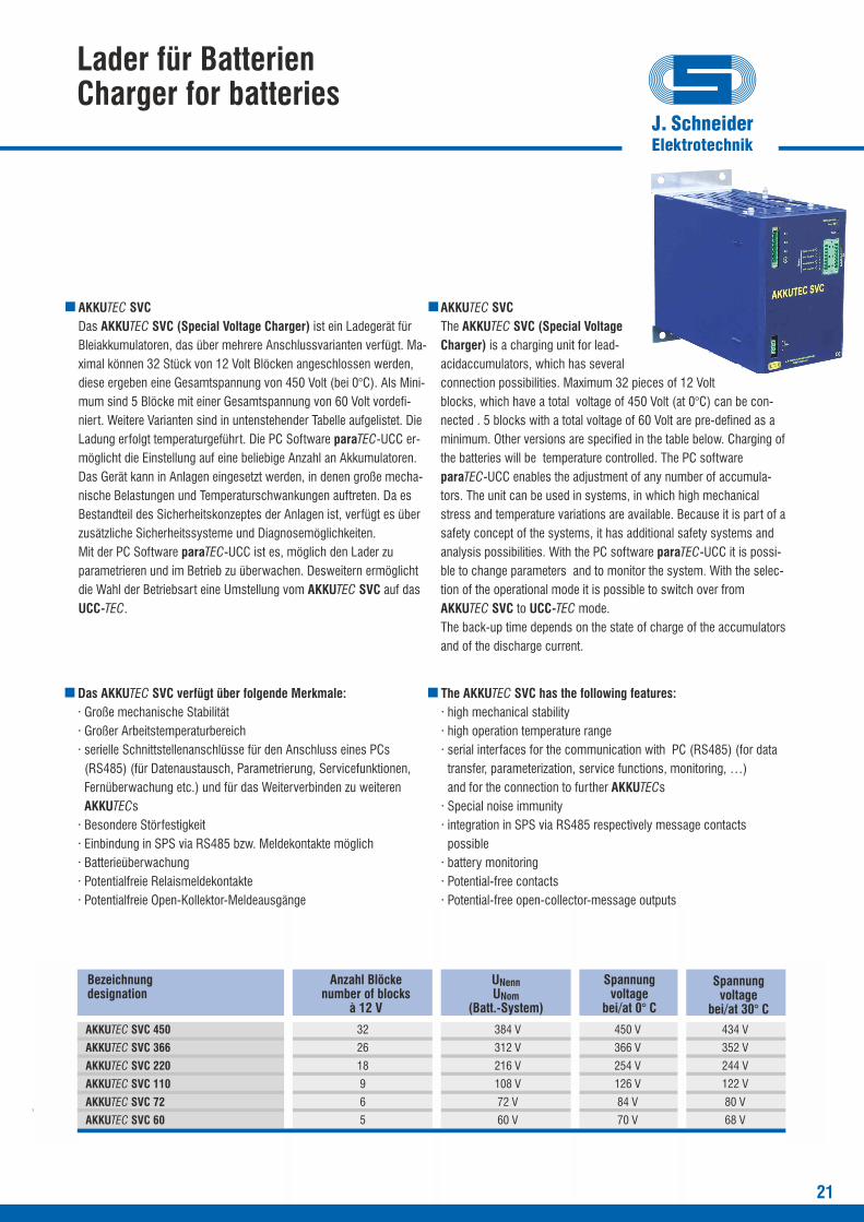
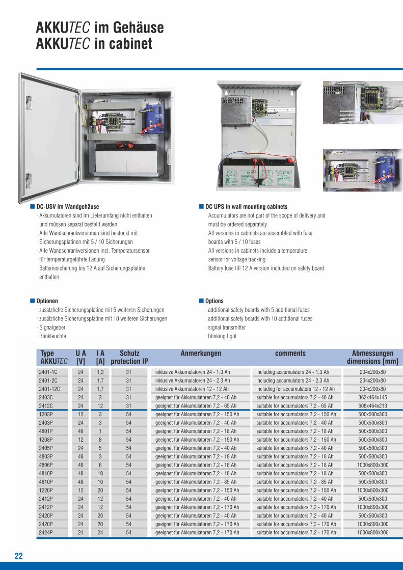
23
AKKUTEC im GehäuseAKKUTEC in cabinet
Type AKKUTEC
U A[V]
I A[A]
Schutzprotection IP
Anmerkungen comments Abmessungendimensions [mm]
2401-1C
2401-2C
2401-12C
2403C
2412C
1203P
2403P
4801P
1208P
2405P
4803P
4806P
4810P
4810P
1220P
2412P
2412P
2420P
2420P
2424P
24
24
24
24
24
12
24
48
12
24
48
48
48
48
12
24
24
24
24
24
1,3
1,7
1,7
3
12
3
3
1
8
5
3
6
10
10
20
12
12
20
20
24
31
31
31
31
31
54
54
54
54
54
54
54
54
54
54
54
54
54
54
54
inklusive Akkumulatoren 24 - 1,3 Ah
inklusive Akkumulatoren 24 - 2,3 Ah
inklusive Akkumulatoren 12 - 12 Ah
geeignet für Akkumulatoren 7,2 - 40 Ah
geeignet für Akkumulatoren 7,2 - 65 Ah
geeignet für Akkumulatoren 7,2 - 150 Ah
geeignet für Akkumulatoren 7,2 - 40 Ah
geeignet für Akkumulatoren 7,2 - 18 Ah
geeignet für Akkumulatoren 7,2 - 150 Ah
geeignet für Akkumulatoren 7,2 - 40 Ah
geeignet für Akkumulatoren 7,2 - 18 Ah
geeignet für Akkumulatoren 7,2 - 18 Ah
geeignet für Akkumulatoren 7,2 - 18 Ah
geeignet für Akkumulatoren 7,2 - 85 Ah
geeignet für Akkumulatoren 7,2 - 150 Ah
geeignet für Akkumulatoren 7,2 - 40 Ah
geeignet für Akkumulatoren 7,2 - 170 Ah
geeignet für Akkumulatoren 7,2 - 40 Ah
geeignet für Akkumulatoren 7,2 - 170 Ah
geeignet für Akkumulatoren 7,2 - 170 Ah
including accumulators 24 - 1,3 Ah
including accumulators 24 - 2,3 Ah
including for accumulators 12 - 12 Ah
suitable for accumulators 7,2 - 40 Ah
suitable for accumulators 7,2 - 65 Ah
suitable for accumulators 7,2 - 150 Ah
suitable for accumulators 7,2 - 40 Ah
suitable for accumulators 7,2 - 18 Ah
suitable for accumulators 7,2 - 150 Ah
suitable for accumulators 7,2 - 40 Ah
suitable for accumulators 7,2 - 18 Ah
suitable for accumulators 7,2 - 18 Ah
suitable for accumulators 7,2 - 18 Ah
suitable for accumulators 7,2 - 85 Ah
suitable for accumulators 7,2 - 150 Ah
suitable for accumulators 7,2 - 40 Ah
suitable for accumulators 7,2 - 170 Ah
suitable for accumulators 7,2 - 40 Ah
suitable for accumulators 7,2 - 170 Ah
suitable for accumulators 7,2 - 170 Ah
204x200x80
204x200x80
204x200x80
362x464x145
608x464x213
500x500x300
500x500x300
500x500x300
500x500x300
500x500x300
500x500x300
1000x800x300
500x500x300
500x500x300
1000x800x300
500x500x300
1000x800x300
500x500x300
1000x800x300
1000x800x300
DC-USV im Wandgehäuse
· Akkumulatoren sind im Lieferumfang nicht enthalten
und müssen separat bestellt werden
· Alle Wandschrankversionen sind bestückt mit
Sicherungsplatinen mit 5 / 10 Sicherungen
· Alle Wandschrankversionen incl. Temperatursensor
für temperaturgeführte Ladung
· Batteriesicherung bis 12 A auf Sicherungsplatine
enthalten
DC UPS in wall mounting cabinets
· Accumulators are not part of the scope of delivery and
must be ordered separately
· All versions in cabinets are assembled with fuse
boards with 5 / 10 fuses
· All versions in cabinets include a temperature
sensor for voltage tracking
· Battery fuse till 12 A version included on safety board
Optionen
· zusätzliche Sicherungsplatine mit 5 weiteren Sicherungen
· zusätzliche Sicherungsplatine mit 10 weiteren Sicherungen
· Signalgeber
· Blinkleuchte
Options
· additional safety boards with 5 additional fuses
· additional safety boards with 10 additional fuses
· signal transmitter
· blinking light
22
SoftwareTECControl · paraTEC
TECControl Software
Die TECControl Software überwacht permanent das Netz sowie den
Ladezustand des Energiespeichers der USV Anlage.
Bei Netzausfall fährt der IPC nach einer einzustellenden Zeit einen
System-Shutdown. Anschließend wird sowohl die USV als auch
der IPC abgeschaltet. Bei Netzwiederkehr gibt die USV die Aus-
gangsspannung frei, so dass das System automatisch neu starten
kann.
The TECControl software monitors continuously both the mains
voltage and the charge status of the UPS energystorage system.
In case of a mains failure, the IPC shuts down the system after a
selected time. Both the UPS and the IPC will then be switched off.
Once mains power is back again, the UPS releases the output volt-
age, allowing the system to restart automatically.
paraTEC Software
Mit Hilfe der Parametriersoftware paraTEC können die Schneider
DC-USV-Anlagen an bestimmte Kundenbedürfnisse angepasst wer-
den.
with the paraTEC Software the Schneider DC-UPS systems can be
programmed to special customer requirements.
paraTEC VdS Software
Mit der Parametiersoftware paraTEC VdS können alle AKKUTEC
VdS –Anlagen (außer AKKUTEC 2401 VdS) an spezifischen Kun-
denbedürfnisse angepasst werden. Mit ihr erfolgt auch die Zu-
standsanzeige (Spannung, Strom, Fehler).
With the paraTEC VdS Software the AKKUTEC VdS systems (not
AKKUTEC 2401VdS) can be adapted to special customer require-
ments. The status of voltage, current and error is also monitored
with this software.
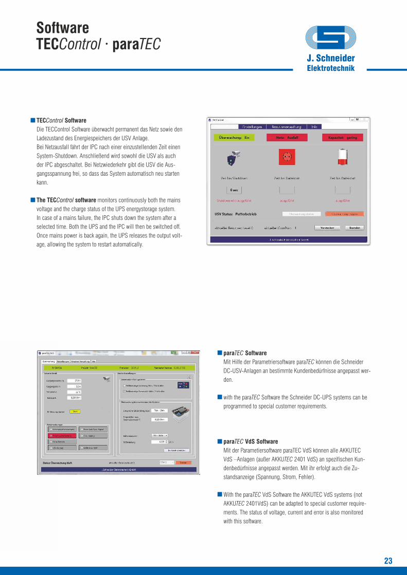
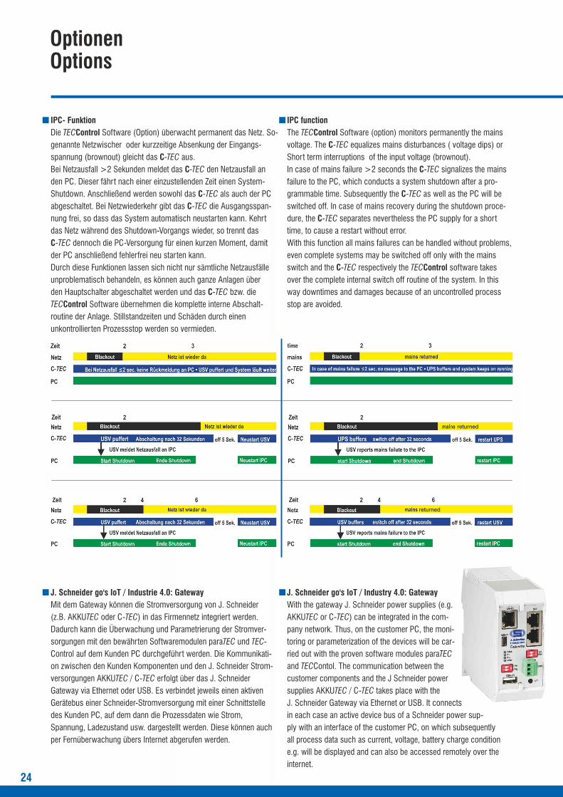
2524
OptionenOptions
drei
phas
ig
· t
hree
-pha
se
IPC- Funktion
Die TECControl Software (Option) überwacht permanent das Netz. So-
genannte Netzwischer oder kurzzeitige Absenkung der Eingangs-
spannung (brownout) gleicht das C-TEC aus.
Bei Netzausfall >2 Sekunden meldet das C-TEC den Netzausfall an
den PC. Dieser fährt nach einer einzustellenden Zeit einen System-
Shutdown. Anschließend werden sowohl das C-TEC als auch der PC
abgeschaltet. Bei Netzwiederkehr gibt das C-TEC die Ausgangsspan-
nung frei, so dass das System automatisch neustarten kann. Kehrt
das Netz während des Shutdown-Vorgangs wieder, so trennt das
C-TEC dennoch die PC-Versorgung für einen kurzen Moment, damit
der PC anschließend fehlerfrei neu starten kann.
Durch diese Funktionen lassen sich nicht nur sämtliche Netzausfälle
unproblematisch behandeln, es können auch ganze Anlagen über
den Hauptschalter abgeschaltet werden und das C-TEC bzw. die
TECControl Software übernehmen die komplette interne Abschalt-
routine der Anlage. Stillstandzeiten und Schäden durch einen
unkontrollierten Prozessstop werden so vermieden.
J. Schneider go's IoT / Industrie 4.0: Gateway
Mit dem Gateway können die Stromversorgung von J. Schneider
(z.B. AKKUTEC oder C-TEC) in das Firmennetz integriert werden.
Dadurch kann die Überwachung und Parametrierung der Stromver-
sorgungen mit den bewährten Softwaremodulen paraTEC und TEC-
Control auf dem Kunden PC durchgeführt werden. Die Kommunikati-
on zwischen den Kunden Komponenten und den J. Schneider Strom-
versorgungen AKKUTEC / C-TEC erfolgt über das J. Schneider
Gateway via Ethernet oder USB. Es verbindet jeweils einen aktiven
Gerätebus einer Schneider-Stromversorgung mit einer Schnittstelle
des Kunden PC, auf dem dann die Prozessdaten wie Strom,
Spannung, Ladezustand usw. dargestellt werden. Diese können auch
per Fernüberwachung übers Internet abgerufen werden.
IPC function
The TECControl Software (option) monitors permanently the mains
voltage. The C-TEC equalizes mains disturbances ( voltage dips) or
Short term interruptions of the input voltage (brownout).
In case of mains failure >2 seconds the C-TEC signalizes the mains
failure to the PC, which conducts a system shutdown after a pro-
grammable time. Subsequently the C-TEC as well as the PC will be
switched off. In case of mains recovery during the shutdown proce-
dure, the C-TEC separates nevertheless the PC supply for a short
time, to cause a restart without error.
With this function all mains failures can be handled without problems,
even complete systems may be switched off only with the mains
switch and the C-TEC respectively the TECControl software takes
over the complete internal switch off routine of the system. In this
way downtimes and damages because of an uncontrolled process
stop are avoided.
J. Schneider go's IoT / Industry 4.0: Gateway
With the gateway J. Schneider power supplies (e.g.
AKKUTEC or C-TEC) can be integrated in the com-
pany network. Thus, on the customer PC, the moni-
toring or parameterization of the devices will be car-
ried out with the proven software modules paraTEC
and TECContol. The communication between the
customer components and the J Schneider power
supplies AKKUTEC / C-TEC takes place with the
J. Schneider Gateway via Ethernet or USB. It connects
in each case an active device bus of a Schneider power sup-
ply with an interface of the customer PC, on which subsequently
all process data such as current, voltage, battery charge condition
e.g. will be displayed and can also be accessed remotely over the
internet.
Entkopplungsdiodensatz bestehend aus einer
Doppel Schottky Diode auf einem potentialfreien
Kühler mit Abdeckung gegen direktes Berühren
und Hutschienenklammer.
Decoupling diode set, consisting of a double
Schottky diode on a potentialfree cooler with
cover against direct contact and DIN rail
connector.
Art.-Nr. TypType
Dauergrenzstrom bei 45° CLimiting average on state current at 45° C
[A]
Sperrspannung Diodeincrease voltage diod
[V]
Breitewidth [mm]
Höheheight [mm]
Tiefedepth [mm]
Entkoppelmodul Decoupling modul
59610.1
59610.2
KGEK002S003M92
KGEK006S001M92
2 x 25 A
2 x 50 A
100 V
45 V
75
100
40
80
90
110
Optionen / options
TEC-Control Lizenz / licence
TEC-Control CD-ROM
Kabel / cable A
Kabel / cable B
Kabel / cable C1
Kabel / cable C2
Kabel / cable C3
USB 2.0 Kabel / cable
IPC Schaltmodul / switch module
Bedien- & Anzeigepanel /
display, control panel
Temperatursensor /
temperature sensor
Sicherungsplatine
fuse board
Shutdown Software als Lizenz / as licence
Shutdown Software als / as CD-ROM
für / for AKKUTEC 2402/2403 & AKKUTEC 2405 & C-TEC 2405/2408/2410 seriell / in series
9 Pol Sub D 1:1 für / for AKKUTEC 2403 DC
Kabel für / cable for AKKUTEC 2410-2440 1,2 M
Kabel für / cable for AKKUTEC 2410-2440 5 M
Kabel für / cable for AKKUTEC 2410-2440 10 M
für/for C-TEC, AC C-TEC, von/from A zu/to B mit Ferrit, 0,5 m Länge/length
für / for AKKUTEC 2402, 2403, 2410
für / for AKKUTEC 2410-2440
für / for AKKUTEC 2410-2440
für / for AKKUTEC 2402/2403 & AKKUTEC 2405 seriell / in series
für/for FKS-Sicherungen/fuses mit/with max. 5 A, bestückt mit /equipped with 5 Sicherungen/fuses à 1 A,
Erweiterung/extension for IP31 Schrank/cabinet 3 A
für/for FKS-Sicherungen/fuses mit/with max. 15 A, bestückt mit /equipped with 10 Sicherungen/fuses à 1 A,
Erweiterung/extension for IP31 Schrank/cabinet 12 A
für/for FKS-Sicherungen/fuses mit/with max. 5 A, bestückt mit /equipped with 5 Sicherungen/fuses à 1 A,
Erweiterung/extension for IP54 Schrank/cabinet,
Schnappbesfestigung für Trageschienen/snap-on mounting for DIN rail
für/for FKS-Sicherungen/fuses mit/with max. 15 A, bestückt mit /equipped with 10 Sicherungen/fuses à 1 A,
Erweiterung/extension for IP54 Schrank/cabinet,
Schnappbesfestigung für Trageschienen/snap-on mounting for DIN rail
returned
returned
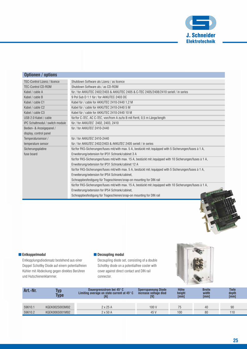
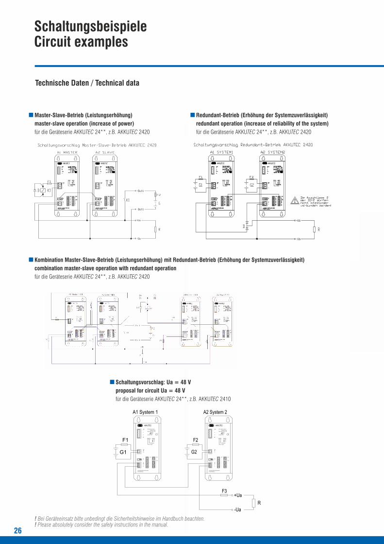
2726
SchaltungsbeispieleCircuit examples
USV im SchaltschrankUPS in cabinet
Technische Daten / Technical data
Master-Slave-Betrieb (Leistungserhöhung)
master-slave operation (increase of power)
für die Geräteserie AKKUTEC 24**, z.B. AKKUTEC 2420
Redundant-Betrieb (Erhöhung der Systemzuverlässigkeit)
redundant operation (increase of reliability of the system)
für die Geräteserie AKKUTEC 24**, z.B. AKKUTEC 2420
Schaltungsvorschlag: Ua = 48 V
proposal for circuit Ua = 48 V
für die Geräteserie AKKUTEC 24**, z.B. AKKUTEC 2410
! Bei Geräteeinsatz bitte unbedingt die Sicherheitshinweise im Handbuch beachten.! Please absolutely consider the safety instructions in the manual.
12A ext
Pb-Akku
Batt
Ua
J.Schneider Elektrotechnik GmbH
D-77652 Offenburg
AKKUTEC
1CS
IO-11
2
3
4
5
6
7
8
9
IO-21
2
IO-31
2
3
4
5
6
L
N
nc
230V
Fehler
Netzbetrieb
UU
ta=0-40°C IP20
PRI: 230V AC +10/-15
SEC: 24V DC nom. / 10A
47-63Hz PF~0,98
2
12A ext
7
9
8
6 3
6
5
4
IO-2
Batt
SEC: 24V DC nom. / 10A
47-63Hz PF~0,98
U
ta=0-40°C IP20
PRI: 230V AC +10/-15
Pb-Akku
J.Schneider Elektrotechnik GmbH
D-77652 Offenburg
AKKUTEC
U
Ua
3
IO-11
1CS
Fehler
Netzbetrieb
4
2
1IO-3
1
2
230V
N
nc
L
5
G1 G2
F2F1
+Ua
-Ua
R
F3
A1 System 1 A2 System 2
Kombination Master-Slave-Betrieb (Leistungserhöhung) mit Redundant-Betrieb (Erhöhung der Systemzuverlässigkeit)
combination master-slave operation with redundant operation
für die Geräteserie AKKUTEC 24**, z.B. AKKUTEC 2420
Beispiele kundenspezifischer Anlagen Examples of customer specified UPS systems
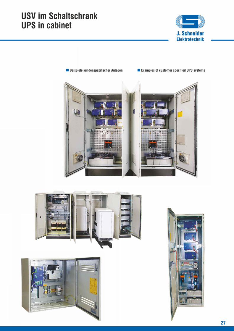
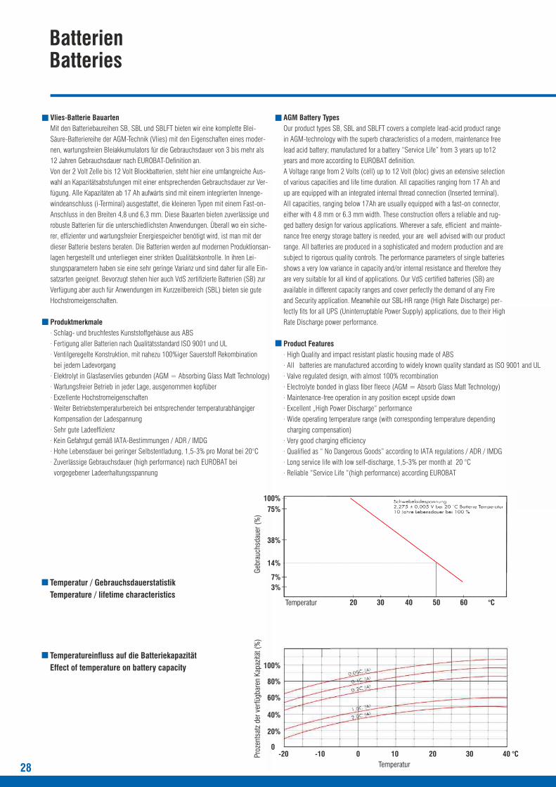
2928
BatterienBatteries
Temperatur / Gebrauchsdauerstatistik
Temperature / lifetime characteristics
Temperatureinfluss auf die Batteriekapazität
Effect of temperature on battery capacity
Vlies-Batterie Bauarten
Mit den Batteriebaureihen SB, SBL und SBLFT bieten wir eine komplette Blei-
Säure-Batteriereihe der AGM-Technik (Vlies) mit den Eigenschaften eines moder-
nen, wartungsfreien Bleiakkumulators für die Gebrauchsdauer von 3 bis mehr als
12 Jahren Gebrauchsdauer nach EUROBAT-Definition an.
Von der 2 Volt Zelle bis 12 Volt Blockbatterien, steht hier eine umfangreiche Aus-
wahl an Kapazitätsabstufungen mit einer entsprechenden Gebrauchsdauer zur Ver-
fügung. Alle Kapazitäten ab 17 Ah aufwärts sind mit einem integrierten Innenge-
windeanschluss (i-Terminal) ausgestattet, die kleineren Typen mit einem Fast-on-
Anschluss in den Breiten 4,8 und 6,3 mm. Diese Bauarten bieten zuverlässige und
robuste Batterien für die unterschiedlichsten Anwendungen. Überall wo ein siche-
rer, effizienter und wartungsfreier Energiespeicher benötigt wird, ist man mit der
dieser Batterie bestens beraten. Die Batterien werden auf modernen Produktionsan-
lagen hergestellt und unterliegen einer strikten Qualitätskontrolle. In ihren Lei-
stungsparametern haben sie eine sehr geringe Varianz und sind daher für alle Ein-
satzarten geeignet. Bevorzugt stehen hier auch VdS zertifizierte Batterien (SB) zur
Verfügung aber auch für Anwendungen im Kurzzeitbereich (SBL) bieten sie gute
Hochstromeigenschaften.
Produktmerkmale
· Schlag- und bruchfestes Kunststoffgehäuse aus ABS
· Fertigung aller Batterien nach Qualitätsstandard ISO 9001 und UL
· Ventilgeregelte Konstruktion, mit nahezu 100%iger Sauerstoff Rekombination
bei jedem Ladevorgang
· Elektrolyt in Glasfaservlies gebunden (AGM = Absorbing Glass Matt Technology)
· Wartungsfreier Betrieb in jeder Lage, ausgenommen kopfüber
· Exzellente Hochstromeigenschaften
· Weiter Betriebstemperaturbereich bei entsprechender temperaturabhängiger
Kompensation der Ladespannung
· Sehr gute Ladeeffizienz
· Kein Gefahrgut gemäß IATA-Bestimmungen / ADR / IMDG
· Hohe Lebensdauer bei geringer Selbstentladung, 1,5-3% pro Monat bei 20°C
· Zuverlässige Gebrauchsdauer (high performance) nach EUROBAT bei
vorgegebener Ladeerhaltungsspannung
AGM Battery Types
Our product types SB, SBL and SBLFT covers a complete lead-acid product range
in AGM-technology with the superb characteristics of a modern, maintenance free
lead acid battery; manufactured for a battery “Service Life” from 3 years up to12
years and more according to EUROBAT definition.
A Voltage range from 2 Volts (cell) up to 12 Volt (bloc) gives an extensive selection
of various capacities and life time duration. All capacities ranging from 17 Ah and
up are equipped with an integrated internal thread connection (Inserted terminal).
All capacities, ranging below 17Ah are usually equipped with a fast-on connector,
either with 4.8 mm or 6.3 mm width. These construction offers a reliable and rug-
ged battery design for various applications. Wherever a safe, efficient and mainte-
nance free energy storage battery is needed, your are well advised with our product
range. All batteries are produced in a sophisticated and modern production and are
subject to rigorous quality controls. The performance parameters of single batteries
shows a very low variance in capacity and/or internal resistance and therefore they
are very suitable for all kind of applications. Our VdS certified batteries (SB) are
available in different capacity ranges and cover perfectly the demand of any Fire
and Security application. Meanwhile our SBL-HR range (High Rate Discharge) per-
fectly fits for all UPS (Uninterruptable Power Supply) applications, due to their High
Rate Discharge power performance.
Product Features
· High Quality and impact resistant plastic housing made of ABS
· All batteries are manufactured according to widely known quality standard as ISO 9001 and UL
· Valve regulated design, with almost 100% recombination
· Electrolyte bonded in glass fiber fleece (AGM = Absorb Glass Matt Technology)
· Maintenance-free operation in any position except upside down
· Excellent „High Power Discharge“ performance
· Wide operating temperature range (with corresponding temperature depending
charging compensation)
· Very good charging efficiency
· Qualified as “ No Dangerous Goods” according to IATA regulations / ADR / IMDG
· Long service life with low self-discharge, 1,5-3% per month at 20 °C
· Reliable “Service Life “(high performance) according EUROBAT
Art.-Nr. Batterietypbattery type
Nennspannungnominal voltage [V]
Kapazität capacity [Ah]
Höheheight [mm]
Breitewidth [mm]
Tiefedepth [mm]
Gewichtweight [kg]
NBBHQ33G1M01
NBBHQ33G1M04
NBBHL33G1M01
NBBHL33G1M02
NBBH0336G01001
NBBH0336G01002
NBBH0336G01003
NBBH0336G01004
452011.47
452011.20
452011.36
452011.22
452011.2
452011.4
452011.8
452011.9
452011.40
452011.53
452011.59
452011.6
NBBH 2401
NBBH 2402
NBBH 2407
NBBH 2412
NBBH 2417
NBBH 2424
NBBH 2440
NBBH 2465
1,3-12
2,2-12
7,2-12L
12-12L
17-12
26-12
40-12
70-12
100-12 sh
120-12 sh
150-12
200-12
24
24
24
24
24
24
24
24
12
12
12
12
12
12
12
12
12
12
12
12
1,2
2,2
7
12
17
24
40
65
1,3
2,2
7,2
12
17
26
40
70
100
120
150
200
96
100
115
115
170
137
170
2 x 170
59
67
94
94
167
125
170
174
215
222
240
218
69
184
174,5
240,5
155
335
335
2 x 335
97
178
151
151
76
175
165
166
171
171
172
522
105
75
159
159
182
200
200
2 x 200
43
35
65
98
181
166
197
350
330
330
485
238
2
3,8
6
9,4
18
20
33
2 x 26
0,85
1,05
2,65
4,1
6,1
8,92
15,7
24
32
38
47
65
Lebensdauer nach Eurobat bis 5 Jahre / life span according to Eurobat till 5 years
Lebensdauer nach Eurobat bis 5 Jahre / life span according to Eurobat till 5 years
Lebensdauer nach Eurobat bis 5 Jahre / life span according to Eurobat till 5 years
Elektrolyt in Glasvlies gebunden / AGM=Absorbing Glass Matt technology in which the electrolyte is absorbed
Akkumulatorensatz incl. Batteriehalterung ohne Batteriesicherung, verschlossen, wartungsfrei, Einbaulage beliebigBattery set including battery fixing and battery fuse, closed, maintenance free, orientation free available
Akkumulator, verschlossen, wartungsfrei, Einbaulage beliebig Battery set, closed, maintenance free, orientation free available
Akkumulatorensatz incl. Batteriehalterung und Batteriesicherung, verschlossen, wartungsfrei, Einbaulage beliebigBattery set including battery fixing and battery fuse, closed, maintenance free, orientation free available
Tiefe/depth 115 mm Tiefe/depth 115 mm
100%
75%
38%
14%
7%
3%
Geb
rauc
hsda
uer
(%)
20 30 40 50 60 °CTemperatur
100%
80%
60%
40%
20%
0
Pro
zent
satz
der
ver
fügb
aren
Kap
azitä
t (%
)
-20 -10 10 20 30 400 °C
Temperatur
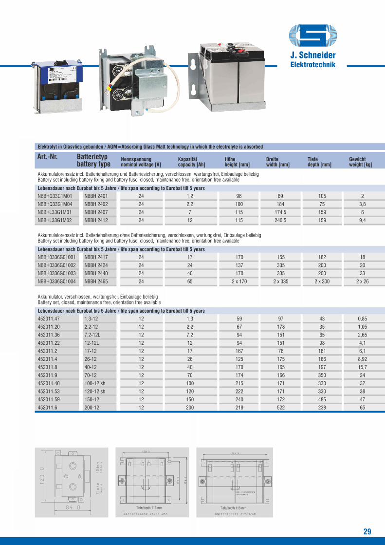
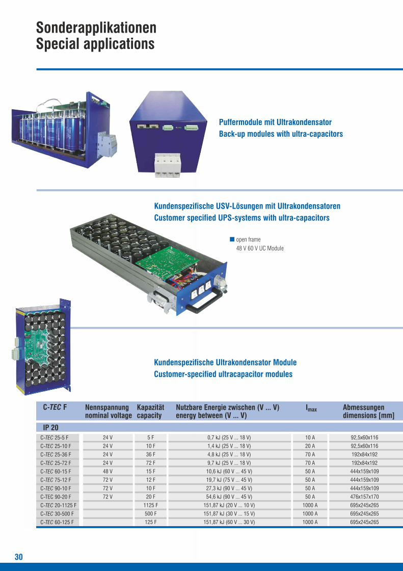
30
SonderapplikationenSpecial applications
WechselricherInverter
C-TEC F
IP 20
Nennspannungnominal voltage
Kapazitätcapacity
Nutzbare Energie zwischen (V ... V)energy between (V ... V)
Abmessungendimensions [mm]
Imax
24 V
24 V
24 V
24 V
48 V
72 V
72 V
72 V
5 F
10 F
36 F
72 F
15 F
12 F
10 F
20 F
1125 F
500 F
125 F
0,7 kJ (25 V ... 18 V)
1,4 kJ (25 V ... 18 V)
4,8 kJ (25 V ... 18 V)
9,7 kJ (25 V ... 18 V)
10,6 kJ (60 V ... 45 V)
19,7 kJ (75 V ... 45 V)
27,3 kJ (90 V ... 45 V)
54,6 kJ (90 V ... 45 V)
151,87 kJ (20 V ... 10 V)
151,87 kJ (30 V ... 15 V)
151,87 kJ (60 V ... 30 V)
10 A
20 A
70 A
70 A
50 A
50 A
50 A
50 A
1000 A
1000 A
1000 A
92,5x60x116
92,5x60x116
192x84x192
192x84x192
444x159x109
444x159x109
444x159x109
476x157x170
695x245x265
695x245x265
695x245x265
C-TEC 25-5 F
C-TEC 25-10 F
C-TEC 25-36 F
C-TEC 25-72 F
C-TEC 60-15 F
C-TEC 75-12 F
C-TEC 90-10 F
C-TEC 90-20 F
C-TEC 20-1125 F
C-TEC 30-500 F
C-TEC 60-125 F
Mit Hilfe eines Victron Energy Sinus Wechselrichters, eines
Ladegeräts und nicht zuletzt einer Batterie mit ausreichender
Kapazität kann eine völlig autonome Energieversorgung aufge-
baut werden. Unsere Geräte werden für unzählige Anwendungen
sowohl an Land, als auch auf Schiffen und überall dort, wo eine
mobile 230V/115V Stromversorgung notwendig ist, eingesetzt.
Die Geräte von Victron Energy sind für alle Arten von elektrischen
Verbrauchern in Technik und Industrie, inklusive empfindlicher In-
strumente geeignet. Victron Energiesysteme sind hochwertige
Energiequellen, die einen störungsfreien Betrieb garantieren.
With the help of a Victron Energy Sine Wave
Inverter, a charger and last but not least a battery
with sufficient capacity, a completely autonomous power
supply can be built up. Our devices are used for lots of
applications both on land and on ships and wherever a mobile
230V / 115V power supply is required. Victron Energy devices
are suitable for all types of electrical consumers in the technical
and industrial sectors, including sensitive instruments. Victron
energy systems are high-quality energy sources that guarantee
trouble-free operation.
open frame
48 V 60 V UC Module
Puffermodule mit Ultrakondensator
Back-up modules with ultra-capacitors
Kundenspezifische Ultrakondensator Module
Customer-specified ultracapacitor modules
Kundenspezifische USV-Lösungen mit Ultrakondensatoren
Customer specified UPS-systems with ultra-capacitors
31
Ausgangsleistung bei 25° C
Ausgangsleistung bei 25° C / 40° C
Spitzenleistung
Wechselstromausgang / Frequenz
Eingangsspannungsbereich
Schutzklasse
Gewicht
Abmessungen
Ausgangsleistung bei 25° C
Ausgangsleistung bei 25° C / 40° C
Spitzenleistung
Wechselstromausgang / Frequenz
Eingangsspannungsbereich
Schutzklasse
Gewicht
Abmessungen
Output rating at 25°C
Output rating at 25°C/40°C
Peak load
AC current output / frequency
Input voltage range
Protective system
Weight
Dimensions
Output rating at 25°C
Output rating at 25°C/40°C
Peak load
AC current output / frequency
Input voltage range
Protective system
Weight
Dimensions
[VA]
[W]
[W]
[V DC]
[kg]
[mm]
[VA]
[W]
[W]
[V DC]
[kg]
[mm]
180
175 / 150
350
IP 20
2,7
72x132x200
1200
1200/900
2400
IP20
10
375x214x110
1600
1300/1200
3000
IP20
10
375x214x110
2000
1600/1450
4000
IP20
12
500x255x125
3000
2500/2200
6000
IP20
18
362x258x218
5000
4500/4000
10000
IP20
30
444x328x240
350
300 / 250
700
IP 20
3,5
72x155x237
110 V AC oder/or 230 V AC +/- 3%
50 Hz oder/or 60 Hz +/- 0,1%
10,5 - 15,5 / 21,0 - 31,0 / 42,0 - 62,0
230 V AC +/- 0,1%
50 Hz +/- 0,1%
9,5 - 17 V / 19 - 33 V / 38 - 66 V
TypePhoenix Inverter
TypePhoenix Inverter
12 Volt24 Volt48 Volt
12 Volt24 Volt48 Volt
12 / 18024 / 180
12 / 120024 / 1200
12 / 160024 / 1600
12 / 200024 / 2000
12 / 300024 / 300048 / 3000
24 / 500048 / 5000
12 / 35024 / 35048 / 350
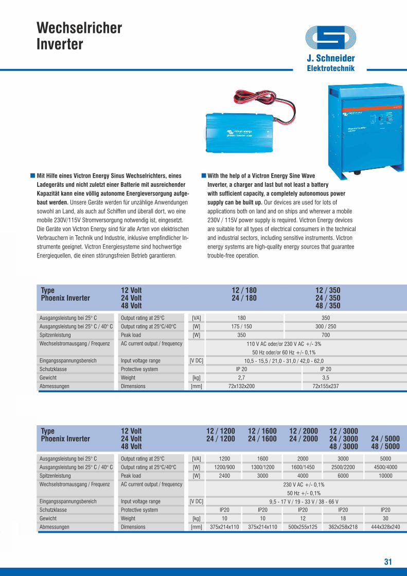
30
SonderapplikationenSpecial applications
WechselricherInverter
C-TEC F
IP 20
Nennspannungnominal voltage
Kapazitätcapacity
Nutzbare Energie zwischen (V ... V)energy between (V ... V)
Abmessungendimensions [mm]
Imax
24 V
24 V
24 V
24 V
48 V
72 V
72 V
72 V
5 F
10 F
36 F
72 F
15 F
12 F
10 F
20 F
1125 F
500 F
125 F
0,7 kJ (25 V ... 18 V)
1,4 kJ (25 V ... 18 V)
4,8 kJ (25 V ... 18 V)
9,7 kJ (25 V ... 18 V)
10,6 kJ (60 V ... 45 V)
19,7 kJ (75 V ... 45 V)
27,3 kJ (90 V ... 45 V)
54,6 kJ (90 V ... 45 V)
151,87 kJ (20 V ... 10 V)
151,87 kJ (30 V ... 15 V)
151,87 kJ (60 V ... 30 V)
10 A
20 A
70 A
70 A
50 A
50 A
50 A
50 A
1000 A
1000 A
1000 A
92,5x60x116
92,5x60x116
192x84x192
192x84x192
444x159x109
444x159x109
444x159x109
476x157x170
695x245x265
695x245x265
695x245x265
C-TEC 25-5 F
C-TEC 25-10 F
C-TEC 25-36 F
C-TEC 25-72 F
C-TEC 60-15 F
C-TEC 75-12 F
C-TEC 90-10 F
C-TEC 90-20 F
C-TEC 20-1125 F
C-TEC 30-500 F
C-TEC 60-125 F
Mit Hilfe eines Victron Energy Sinus Wechselrichters, eines
Ladegeräts und nicht zuletzt einer Batterie mit ausreichender
Kapazität kann eine völlig autonome Energieversorgung aufge-
baut werden. Unsere Geräte werden für unzählige Anwendungen
sowohl an Land, als auch auf Schiffen und überall dort, wo eine
mobile 230V/115V Stromversorgung notwendig ist, eingesetzt.
Die Geräte von Victron Energy sind für alle Arten von elektrischen
Verbrauchern in Technik und Industrie, inklusive empfindlicher In-
strumente geeignet. Victron Energiesysteme sind hochwertige
Energiequellen, die einen störungsfreien Betrieb garantieren.
With the help of a Victron Energy Sine Wave
Inverter, a charger and last but not least a battery
with sufficient capacity, a completely autonomous power
supply can be built up. Our devices are used for lots of
applications both on land and on ships and wherever a mobile
230V / 115V power supply is required. Victron Energy devices
are suitable for all types of electrical consumers in the technical
and industrial sectors, including sensitive instruments. Victron
energy systems are high-quality energy sources that guarantee
trouble-free operation.
open frame
48 V 60 V UC Module
Puffermodule mit Ultrakondensator
Back-up modules with ultra-capacitors
Kundenspezifische Ultrakondensator Module
Customer-specified ultracapacitor modules
Kundenspezifische USV-Lösungen mit Ultrakondensatoren
Customer specified UPS-systems with ultra-capacitors
31
Ausgangsleistung bei 25° C
Ausgangsleistung bei 25° C / 40° C
Spitzenleistung
Wechselstromausgang / Frequenz
Eingangsspannungsbereich
Schutzklasse
Gewicht
Abmessungen
Ausgangsleistung bei 25° C
Ausgangsleistung bei 25° C / 40° C
Spitzenleistung
Wechselstromausgang / Frequenz
Eingangsspannungsbereich
Schutzklasse
Gewicht
Abmessungen
Output rating at 25°C
Output rating at 25°C/40°C
Peak load
AC current output / frequency
Input voltage range
Protective system
Weight
Dimensions
Output rating at 25°C
Output rating at 25°C/40°C
Peak load
AC current output / frequency
Input voltage range
Protective system
Weight
Dimensions
[VA]
[W]
[W]
[V DC]
[kg]
[mm]
[VA]
[W]
[W]
[V DC]
[kg]
[mm]
180
175 / 150
350
IP 20
2,7
72x132x200
1200
1200/900
2400
IP20
10
375x214x110
1600
1300/1200
3000
IP20
10
375x214x110
2000
1600/1450
4000
IP20
12
500x255x125
3000
2500/2200
6000
IP20
18
362x258x218
5000
4500/4000
10000
IP20
30
444x328x240
350
300 / 250
700
IP 20
3,5
72x155x237
110 V AC oder/or 230 V AC +/- 3%
50 Hz oder/or 60 Hz +/- 0,1%
10,5 - 15,5 / 21,0 - 31,0 / 42,0 - 62,0
230 V AC +/- 0,1%
50 Hz +/- 0,1%
9,5 - 17 V / 19 - 33 V / 38 - 66 V
TypePhoenix Inverter
TypePhoenix Inverter
12 Volt24 Volt48 Volt
12 Volt24 Volt48 Volt
12 / 18024 / 180
12 / 120024 / 1200
12 / 160024 / 1600
12 / 200024 / 2000
12 / 300024 / 300048 / 3000
24 / 500048 / 5000
12 / 35024 / 35048 / 350
J. Schneider Elektrotechnik GmbH
Helmholtzstrasse 13
D-77652 Offenburg
Germany
Tel. +49 / (0) 781 / 2 06 -0
Fax +49 / (0) 7 81 / 2 53 18
www.j-schneider.de
Jörg
Sch
aars
chm
idt D
ipl.-
Des
igne
r · w
ww
.j-sc
haar
schm
idt.d
e · Ä
nder
unge
n vo
rbeh
alte
n · M
odifi
catio
ns p
ossi
ble
· 111
7
DC-USV Anlagen / BatterieanlagenDC-UPS systems / battery systems
DC-USV Anlagen 2 A - 600 A
Ultracap-Module 0,2 A - 600 A
DC-UPS systems 2 A - 600 A
Ultracap-modules 0,2 A - 600 A