Embed Size (px)
Citation preview
DESIGNING UNIVERSAL YOKE STRUCTURE OF
SUSPENSION AND RELEASE SYSTEM WITH TOPOLOGY
OPTIMIZATION FOR FIGHTER AIRCRAFTS
TAŞIMA VE BIRAKMA SİSTEMİ PARÇASI
ÇOK AMAÇLI KELEPÇE YAPISININ AVCI UÇAKLAR
İÇİN TOPOLOJİ OPTİMİZASYONU İLE TASARIMI
MELİH KAAN BAL
ASSIST. PROF. DR. ÖZGÜR ÜNVER
Supervisor
Submitted to
Graduate School of Science and Engineering of Hacettepe University
as a Partial Fulfillment to the Requirements
for the Award of the Degree of Master of Science
in Mechanical Engineering
2020
i
ABSTRACT
DESIGNING UNIVERSAL YOKE STRUCTURE OF
SUSPENSION AND RELEASE SYSTEM WITH
TOPOLOGY OPTIMIZATION FOR FIGHTER AIRCRAFTS
Melih Kaan BAL
Master of Science, Department of Mechanical Engineering
Supervisor: Assist. Prof. Dr. Özgür ÜNVER
August 2020, 87 pages
In the aviation industry, a design with a sensitive and low margin is more important than any
vehicle production. Within the scope of this study, the design road map of a product intended
to be used in fighter aircraft is explained and it is aimed to bring an example study to the
literature of our country. Due to the maneuvers of the fighter aircraft and the environmental
conditions, it was desired to find out which loads were affected on this structure. Weapon
systems were selected as sample application, duties and working principles of the suspension
and release systems were explained in detail. General literature and studies about ejector
release units and weapons were examined, information was given about structural design
and lightening studies. Then, loads on the ejector release unit and weapon due to the
movements and environment of the fighter aircraft were calculated. In addition, the forces
required to safely separate these weapons from the aircraft were explained and included in
the process. A multi-purpose and compatible yoke structure has been considered for the
purpose of carrying air-air and air-surface weapon with the same release system, which has
not been applied before. The yoke structure is modeled in the SolidWorks program according
to the requirements.
ii
The material selection from alternatives is aimed to be realistic in terms of our country's
literature and opportunities. In the ABAQUS program, design spaces and constraints were
selected and analyzed using the finite element method under different multi load cases of
beyond vision missile and 1000lb bombs. Necessary weight reduction and topology
optimization studies were carried out with the TOSCA module in the analysis program. The
surface smoothing process was applied to this yoke structure which was optimized and
lightened after the design. Different yoke design alternatives that can be considered
separately for bombs and missiles were also subjected to relevant loads and the resulting
stress values were examined, compared with the current results of the optimization
geometry, and the multi-purpose designed structure was evaluated to be efficient. This
structure, which was calculated as 705 grams after optimization, decreased to the desired
weight level. In the case of maximum loading, 2 as a safety factor has been chosen for the
material yield value. Since the yield strength of the material 17-4PH H1025 is 1170 Mpa,
the analysis results should be less than 585 Mpa. As a result, the maximum stress in the yoke
calculated as 521 MPa and this strength remained below the limit. It was concluded that this
geometry would not create a risky situation for safe flight and seperation after designing
with topology optimization.
Keywords: Flight Loads, Yoke Structure, Suspension and Release Systems, Finite Element
Method, Topology Optimization
iii
ÖZET
TAŞIMA VE BIRAKMA SİSTEMİ PARÇASI ÇOK AMAÇLI KELEPÇE
YAPISININ AVCI UÇAKLAR İÇİN TOPOLOJİ OPTİMİZASYONU İLE
TASARIMI
Melih Kaan BAL
Yüksek Lisans, Makina Mühendisliği Bölümü
Tez Danışmanı: Dr. Öğr. Üyesi Özgür ÜNVER
Ağustos 2020, 87 sayfa
Havacılık sanayisinde hassas ve hata payının az olduğu bir tasarım her araçta olduğundan
daha fazla önem arz etmektedir. Bu çalışma kapsamında avcı uçaklarında kullanılmak
istenen bir ürünün tasarım yol haritası anlatılıp, örnek bir çalışmayı ülkemiz literatürüne
kazandırmak amaçlanmıştır. Tasarlanmak istenen bu yapının uçağın hareketleri ve ortam
şartları sebebiyle hangi yüklerin etkisi altında kaldığı bulunmak istenmiştir. Silah sistemleri
örnek uygulama olarak seçilmiş, taşıma ve bırakma sistemlerinin görevi ve çalışma prensibi
detaylıca anlatılmıştır. Salan ve silahlar hakkında genel literatür ve yapılmış çalışmalar
incelenmiş, yapısal tasarım ile hafifletme çalışmaları hakkında bilgi verilmiştir. Ardından,
uçağın hareketleri ve içinde bulunduğu ortam sebebiyle takılı olan mühimmat ile salan
sisteminin maruz kaldığı yükler hesaplanmıştır. Ayrıca bu mühimmatların uçaktan güvenli
şekilde ayrılması için gereken kuvvetler de anlatılarak işleme katılmıştır. Daha önce
uygulaması bulunmayan, hava hava ve hava yer mühimmatlarını aynı salan sistemiyle
taşıma amacı doğrultusunda çok amaçlı ve uyumlu bir kelepçe yapısı düşünülmüştür.
Kelepçe yapısı SolidWorks programında gereksinimlere uygun modellenmiştir.
iv
Seçenekler arasından malzeme seçimi ülkemiz literatürü ve imkanları açısından gerçekçi
olması hedeflenmiştir. ABAQUS programında tasarım bölgeleri ve sınırlandırmalar
seçilmiş, görüş ötesi füze ve 1000lb bombanın farklı yük senaryoları altında sonlu elemanlar
yöntemi kullanılarak analiz edilmiştir. Gerekli ağırlık azaltma ve topoloji optimizasyonu
çalışmaları analiz programı içerisindeki TOSCA modülü ile yapılmıştır. Tasarım sonrası
ortaya çıkan optimize edilerek hafifletilmiş bu kelepçe yapısına yüzey yumuşatma işlemi
yapılmıştır. Bomba ve füzeler için ayrı ayrı düşünülebilecek farklı kelepçe tasarım
alternatifleri yine ilgili yüklere maruz bırakılarak ortaya çıkan gerilme değerleri incelenmiş,
optimizasyon geometrisinin mevcut sonuçları ile karşılaştırılmış ve çok amaçlı tasarlanan
yapının verimli olduğu değerlendirilmiştir. Optimizasyon sonrası 705 gram hesaplanan bu
yapı istenen ağırlık seviyesine inmiştir. Maksimum yükleme durumunda malzeme akma
değeri için güvenlik katsayısı 2 seçilmiştir. Malzeme 17-4PH H1025’in akma dayanımı 1170
Mpa olması sebebiyle, analiz sonuçları 585 Mpa’dan küçük olmalıdır. Sonuç olarak kelepçe
maksimum 521 MPa ile yorulma dayanımı sınırın altında kalmış, topoloji optimizasyonu
sonrası güvenli uçuş ve ayrılma için bir risk oluşturmayacağı kanaatine varılmıştır.
Anahtar Kelimeler: Uçuş Yükleri, Kelepçe Yapısı, Taşıma ve Bırakma Sistemleri, Sonlu
Elemanlar Yöntemi, Topoloji Optimizasyonu
v
ACKNOWLEDGEMENTS
Firstly, I would like to express my deepest gratitude my supervisor Assist. Prof. Dr. Özgür
ÜNVER who made a great contribution in the creation of this thesis, supported me with his
knowledge, guidance and experience at every stage of the study. I also appreciate to all
instructors and my institute for their expressions on my study and for this chance.
I would also like to thank my colleagues, my section lead Mr. Semih Gökhan KUŞHAN and
my manager Mr. Mehmet Serol DOĞANER for technical supports and significant
contributions to my comprehension in weapon systems. I am grateful to Prof. Dr.
Mustafa CAVCAR, other managers and my company TURKISH AEROSPACE for their
understanding of my absences.
Most of all, I would like to express my thankfulness to my family who were always
supportive and patient.
Melih Kaan Bal
August 2020, Ankara
vi
TABLE OF CONTENTS
ABSTRACT ...................................................................................................................... i
ÖZET ................................................................................................................................ iii
ACKNOWLEDGEMENTS ............................................................................................... v
LIST OF FIGURES ........................................................................................................ viii
LIST OF TABLES ........................................................................................................... xi
LIST OF SYMBOLS AND ABBREVIATIONS ............................................................. xii
1 INTRODUCTION .................................................................................................... 1
1.1 Problem Definition .............................................................................................. 1
1.2 Motivation ........................................................................................................... 1
1.3 Challenges ........................................................................................................... 2
2 LITERATURE SURVEY ......................................................................................... 3
2.1 Literature of Weapon Systems ............................................................................. 3
2.2 Literature of Aircraft Weapons............................................................................. 6
2.3 Suspension and Release Equipment ..................................................................... 8
2.3.1 Working Principle ......................................................................................... 9
2.3.2 Different Types of SARE ............................................................................ 12
2.3.3 Necessity of Sway Braces and Yoke Structure ............................................ 14
2.4 Brief Literature of Topology Optimization ......................................................... 16
3 THEORY ............................................................................................................... 19
3.1 Load Calculation for Aircraft Equipment ........................................................... 19
3.1.1 Physical Characteristics for Store ................................................................ 20
3.1.2 Inertial Load Equations ............................................................................... 21
3.1.3 Aerodynamic Load Equations ..................................................................... 27
3.2 Force Calculation for Specific Weapon Release ................................................. 35
3.3 Final Design Structural Optimization ................................................................. 40
3.3.1 Size Optimization........................................................................................ 41
3.3.2 Shape Optimization ..................................................................................... 41
3.3.3 Topology Optimization ............................................................................... 42
vii
4 METHODOLOGY FOR YOKE STRUCTURE AS A CASE STUDY.................... 47
4.1 Combining Total Forces for Universal Yoke Structure ....................................... 47
4.2 Design Space of the Base Universal Structure .................................................... 49
4.3 FE Model Creation ............................................................................................. 53
4.4 Material Property ............................................................................................... 54
4.5 Multiple Load Condition Definition ................................................................... 55
4.6 Stress Analysis ................................................................................................... 56
4.7 Design and Non-Design Space Definitions and Design Variables ....................... 59
4.8 Response, Objective and Constraint Function ..................................................... 60
4.9 Geometric Restrictions ....................................................................................... 62
4.10 Results Monitoring of Topology Optimization ................................................... 63
4.11 Optimization Results Smoothing ........................................................................ 64
4.12 Latest Design and Analysis of Universal Yoke Structure .................................... 65
4.13 Comparison with Alternative Geometries ........................................................... 66
4.13.1 Alternative Geometries ................................................................................ 66
4.13.2 Stress Analyses and Comparison ................................................................. 69
5 CONCLUSION & FUTURE WORKS .................................................................... 71
REFERENCES ................................................................................................................ 74
APPENDICES ................................................................................................................. 79
viii
LIST OF FIGURES
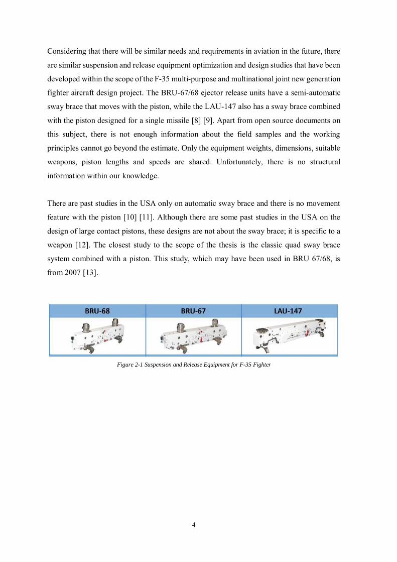
Figure 2-1 Suspension and Release Equipment for F-35 Fighter ........................................ 4
Figure 2-2 Suspension and Release Equipment for PAK FA Fighter .................................. 5
Figure 2-3 AIM-120 AMRAAM........................................................................................ 6
Figure 2-4 F/A-22 Weapon Configuration ......................................................................... 7
Figure 2-5 GBU-39 Specifications ..................................................................................... 7
Figure 2-6 MK-82 Drawing ............................................................................................... 8
Figure 2-7 Ejector Release Unit Subsystem Representation ............................................... 9
Figure 2-8 Pneumatic and Pyrotechnic Ejector Release Unit ............................................ 10
Figure 2-9 Movement of Hooks Representative ............................................................... 10
Figure 2-10 Mechanism Example with Hooks, Lugs and Swaybraces .............................. 11
Figure 2-11 Piston Mechanism Working Principle Representation ................................... 11
Figure 2-12 LDERU Example ......................................................................................... 12
Figure 2-13 HDERU Example ......................................................................................... 12
Figure 2-14 Rail Launcher Examples ............................................................................... 13
Figure 2-15 Missile Vertical Ejection Launchers Examples ............................................ 13
Figure 2-16 Sway Brace and Usage ................................................................................. 14
Figure 2-17 Piston and Usage .......................................................................................... 14
Figure 2-18 Yoke Structure and Usage ............................................................................ 15
Figure 3-1 Axis of Three Dimensional Flight ................................................................... 22
Figure 3-2 Inertia Limit Load Factors of Catapult and Arrested Landing at Wings ........... 25
Figure 3-3 Inertia Limit Load Factors of Catapult and Arrested Landing at Fuselage ....... 26
Figure 3-4 Angles of Attack and Sideslip for Load Envelopes ......................................... 29
Figure 3-5 Lift, Drag, Side Force, Pitch and Yaw Moment Coefficients Plots .................. 30
Figure 3-6 Drag Coefficients and Mach Plots .................................................................. 31
Figure 3-7 Flight Aerodynamic Forces for Stores ............................................................ 31
Figure 3-8 Top, Side and End views of Sway brace and Weapon Interfaces from [37] ..... 33
Figure 3-9 Mau-12 Ejector Release Unit .......................................................................... 36
Figure 3-10 Force Time Plot of Mau-12........................................................................... 37
Figure 3-11 Ejector Simulink Model ................................................................................ 37
Figure 3-12 Ejector Simulink Model Results ................................................................... 38
Figure 3-13 Structural Optimization Methods [41] ........................................................... 40
Figure 3-14 Topology Optimization from ABAQUS User Guide ..................................... 42
ix
Figure 3-15 ABAQUS –TOSCA cycle ............................................................................. 46
Figure 4-1 F-35 Fighter Aircraft with Weapons ................................................................ 47
Figure 4-2 Missile And Different Vertical Eject Launchers .............................................. 49
Figure 4-3 Recent Ejector Release Units .......................................................................... 50
Figure 4-4 Solidworks Drawing of Design Space with Different Weapons ....................... 51
Figure 4-5 Sway Brace and Yoke Examples ..................................................................... 52
Figure 4-6 Solidworks Drawing of Design Space ............................................................ 52
Figure 4-7 Finite Element Model of Structure .................................................................. 53
Figure 4-8 a) Grade 250 maraging steel (b) AISI 4340M Steel (c) 17-4PH H1025 ........... 54
Figure 4-9 Ejection Force to Sway brace .......................................................................... 55
Figure 4-10 Ejection Force to Yoke ................................................................................. 55
Figure 4-11 Fixing Reaction Force to Sway brace ............................................................ 56
Figure 4-12 Fixing Reaction Force to Yoke ...................................................................... 56
Figure 4-13 Stress analysis result of Ejecting Load Case of Missile ................................. 57
Figure 4-14 Stress analysis result of Fixing Load Case of Missile .................................... 57
Figure 4-15 Stress analysis result of Ejecting Load Case of Bomb ................................... 58
Figure 4-16 Stress analysis result of Fixing Load Case of Bomb ...................................... 58
Figure 4-17 Design and non-design features ..................................................................... 59
Figure 4-18 Abaqus Screenshots to Edit Design Response ............................................... 60
Figure 4-19 Abaqus Screenshots to Edit Objective Function ............................................ 61
Figure 4-20 Abaqus Screenshots to Edit Constraint .......................................................... 61
Figure 4-21 Abaqus Screenshots to Edit Geometric Restriction ........................................ 62
Figure 4-22 Stiffness Maximization and Volume Reducing Monitoring for the Structure . 63
Figure 4-23 Displacements of Optimized Geometry ......................................................... 63
Figure 4-24 Density of Optimized Geometry.................................................................... 64
Figure 4-25 Smoothing After Optimization ...................................................................... 64
Figure 4-26 Stress Values of Optimized Geometry ........................................................... 65
Figure 4-27 Solidworks Drawing of Alternative Design 1 ................................................ 66
Figure 4-28 Solidworks Drawing of Alternative Design 2 ................................................ 67
Figure 4-29 Solidworks Drawing of Alternative Design 3 ................................................ 67
Figure 4-30 Solidworks Drawing of Alternative Design 4 ................................................ 68
Figure 4-31 Solidworks Drawing of Alternative Design 5 ................................................ 68
Figure 5-1 Front and Side Views of Base and. Final Optimized Design ............................ 71
Figure 5-2 Designed Structures with Air-Air Missile ....................................................... 72
x
Figure 5-3 Designed Structures with Air-Surface 1000lb Bomb ....................................... 72
xi
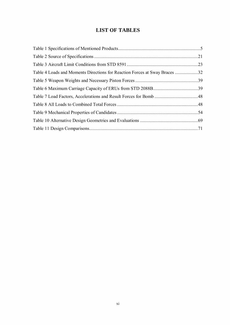
LIST OF TABLES
Table 1 Specifications of Mentioned Products ....................................................................5
Table 2 Source of Specifications ...................................................................................... 21
Table 3 Aircraft Limit Conditions from STD 8591 ........................................................... 23
Table 4 Loads and Moments Directions for Reaction Forces at Sway Braces ................... 32
Table 5 Weapon Weights and Necessary Piston Forces .................................................... 39
Table 6 Maximum Carriage Capacity of ERUs from STD 2088B..................................... 39
Table 7 Load Factors, Accelerations and Result Forces for Bomb .................................... 48
Table 8 All Loads to Combined Total Forces ................................................................... 48
Table 9 Mechanical Properties of Candidates ................................................................... 54
Table 10 Alternative Design Geometries and Evaluations ................................................ 69
Table 11 Design Comparisons.......................................................................................... 71
xii
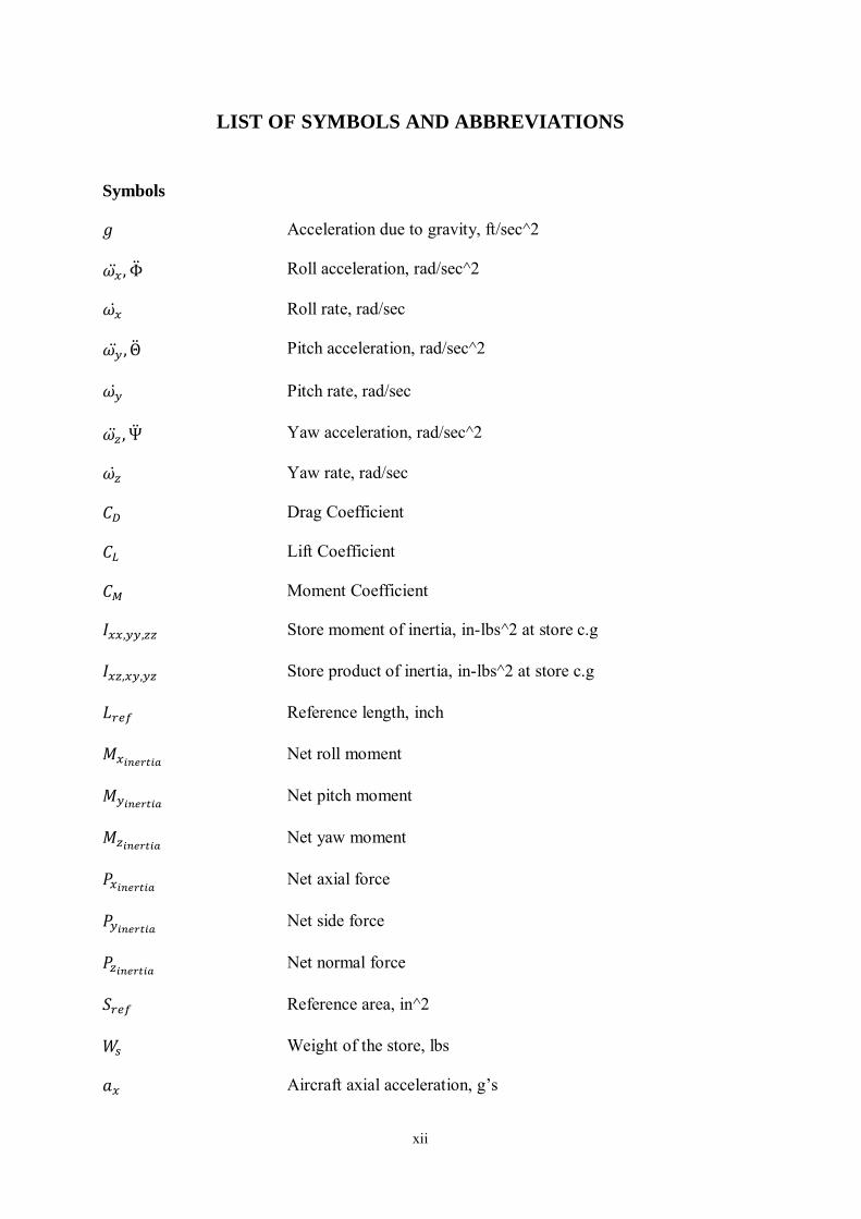
LIST OF SYMBOLS AND ABBREVIATIONS
Symbols
𝑔 Acceleration due to gravity, ft/sec^2
𝜔�̈� , Φ̈ Roll acceleration, rad/sec^2
𝜔�̇� Roll rate, rad/sec
𝜔�̈� , Θ̈ Pitch acceleration, rad/sec^2
𝜔�̇� Pitch rate, rad/sec
𝜔�̈� , Ψ̈ Yaw acceleration, rad/sec^2
𝜔�̇� Yaw rate, rad/sec
𝐶𝐷 Drag Coefficient
𝐶𝐿 Lift Coefficient
𝐶𝑀 Moment Coefficient
𝐼𝑥𝑥,𝑦𝑦,𝑧𝑧 Store moment of inertia, in-lbs^2 at store c.g
𝐼𝑥𝑧,𝑥𝑦,𝑦𝑧 Store product of inertia, in-lbs^2 at store c.g
𝐿𝑟𝑒𝑓 Reference length, inch
𝑀𝑥𝑖𝑛𝑒𝑟𝑡𝑖𝑎 Net roll moment
𝑀𝑦𝑖𝑛𝑒𝑟𝑡𝑖𝑎 Net pitch moment
𝑀𝑧𝑖𝑛𝑒𝑟𝑡𝑖𝑎 Net yaw moment
𝑃𝑥𝑖𝑛𝑒𝑟𝑡𝑖𝑎 Net axial force
𝑃𝑦𝑖𝑛𝑒𝑟𝑡𝑖𝑎 Net side force
𝑃𝑧𝑖𝑛𝑒𝑟𝑡𝑖𝑎 Net normal force
𝑆𝑟𝑒𝑓 Reference area, in^2
𝑊𝑠 Weight of the store, lbs
𝑎𝑥 Aircraft axial acceleration, g’s
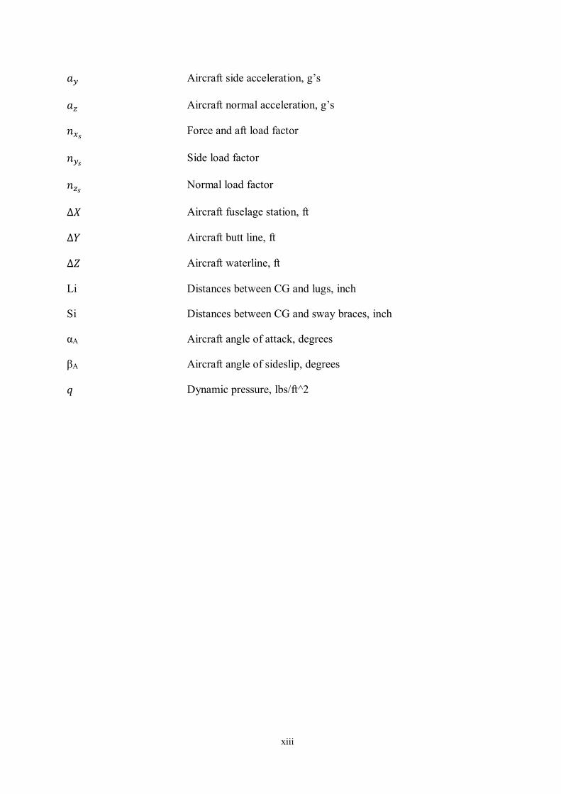
xiii
𝑎𝑦 Aircraft side acceleration, g’s
𝑎𝑧 Aircraft normal acceleration, g’s
𝑛𝑥𝑠 Force and aft load factor
𝑛𝑦𝑠 Side load factor
𝑛𝑧𝑠 Normal load factor
∆𝑋 Aircraft fuselage station, ft
∆𝑌 Aircraft butt line, ft
∆𝑍 Aircraft waterline, ft
Li Distances between CG and lugs, inch
Si Distances between CG and sway braces, inch
αA Aircraft angle of attack, degrees
βA Aircraft angle of sideslip, degrees
𝑞 Dynamic pressure, lbs/ft^2
xiv
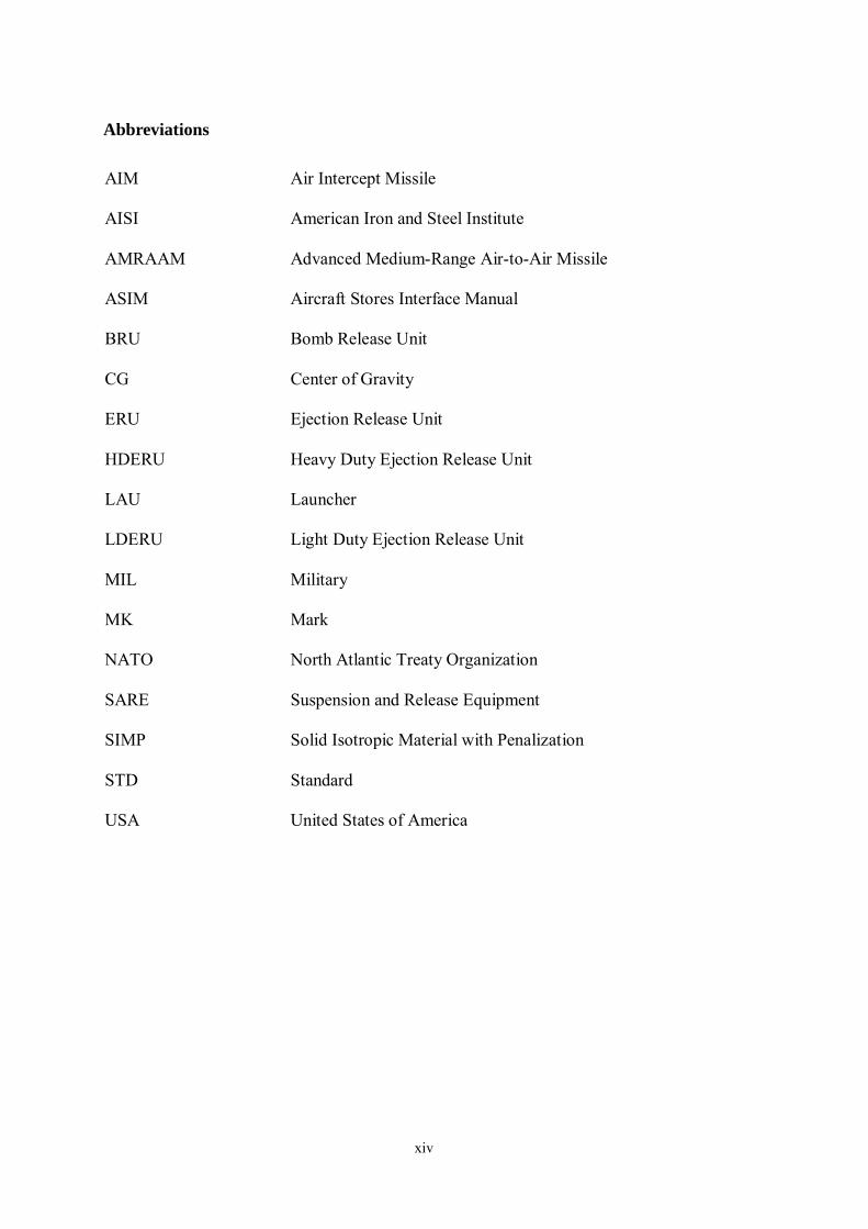
Abbreviations
AIM Air Intercept Missile
AISI American Iron and Steel Institute
AMRAAM Advanced Medium-Range Air-to-Air Missile
ASIM Aircraft Stores Interface Manual
BRU Bomb Release Unit
CG Center of Gravity
ERU Ejection Release Unit
HDERU Heavy Duty Ejection Release Unit
LAU Launcher
LDERU Light Duty Ejection Release Unit
MIL Military
MK Mark
NATO North Atlantic Treaty Organization
SARE Suspension and Release Equipment
SIMP Solid Isotropic Material with Penalization
STD Standard
USA United States of America
1
1 INTRODUCTION
1.1 Problem Definition
Suspension and release equipment are systems that are between the weapon and the aircraft
structure, developed to captive carry weapon during any flight maneuver and to
release/launch it from the aircraft with pneumatic, pyrotechnic or electromechanical
propulsion systems when commanded.
Since they are in the mass group in the fuselage and wings of aircraft, they are required to
be as low as possible. Weapon suspension and release equipment are expected to withstand
a variety of loads as they are critical mission equipment.
Due to the weight of the carried weapon and the capacity of the compatible weapon diameter,
suspension equipment is preferred differently for air to air and air to surface operations.
1.2 Motivation
The main goal of this thesis is to introduce a basic method that can be used by anyone who
wants to develop any product on the fighter aircraft and can be used in the calculation of the
forces on this related product, especially for the literature of our country. Developing
competition in the aviation industry, the integration of different platforms on the battlefield,
reveals the need to use the volume efficiently by designing the aircraft more and more every
day. When it comes to the fighter aircraft, it is also important that the products to be designed
will be exposed to which loads under which conditions. It has been evaluated that it is critical
to ensure the safe suspension and separation of the weapon systems, which are the main
purpose of combat aircraft, the suspension and release system, which is a difficult example,
has been chosen and how to reduce the weight, which is very important in the aviation
industry, has also been demonstrated using the optimization method. In addition, while
designing this product, it is aimed to be suitable for different purpose weapons, which has
not been seen in the literature before.
It is aimed to design and optimize yoke structure, which is mentioned in the literature as a
part of the weapon suspension and release equipment, by applying changes in the geometry
of universally suitable for the diameters of both air to surface and air-to-air weapon without
2
the need for separate sway braces with the demonstration of design process and methods for
the first time and contribute to the literature of our country as a guideline.
For this purpose, first, reaction forces will be found from calculated ejector forces for
different weapons in the literature which have various weight classes, load and moment
calculations will be computed for one or more weapon during various maneuvers for a
selected generic fighter aircraft, the reaction forces on the sway braces will be calculated. In
line with information obtained, static analyses will be carried out in the ABAQUS program
with the finite element analysis for a yoke structure that drawn according to the need. The
effects on the stress intensity and weight will be examined and compared with equivalent
geometries according to the weight and topology optimization studies with ABAQUS
TOSCA.
1.3 Challenges
In order to design a structure on the aircraft, the physical conditions of the region where it
will be located must be known, and for this purpose, the loads and environmental impacts
must be calculated. In order to make all these calculations, an aircraft with available
information should be used, and if it is planned to be designed, it should be compared to
known aircraft.
The same difficulty exists when the structure to be designed is part of the suspension and
release system. The information of the weapon to be ejected and carried should be known
from literature or calculated in the static test rig.
During the calculation of the impact of the weapon on the suspension and release equipment,
a sample must be found and its similarity with the new release system must be known.
Within the scope of this study, points mentioned below can be expressed as difficulties to
find information especially using open source;
Generic fighter aircraft
Generic suspension and release system
Generic weapon
3
2 LITERATURE SURVEY
2.1 Literature of Weapon Systems
When the military aviation literature is examined, it is seen that the studies carried out are
shared with limited publications. It is considered that the reason for the limited publications
is that most of the topics are evaluated within the scope of national knowledge and that they
are critical for the development of the defence industry.
Schoppert tried to determine the reaction forces coming from the carried weapons to a
designated suspension and release equipment and compared them with ground-flight tests
[1]. Xiao-guang et al. [2] have tried to optimize and design hydraulic and control systems in
missile launch systems and examined parameters such as wind, launch forces and launch
angle.
In their work, XieJian et al. [3] focused on the influence and direction of the wind and the
impact of these variables on missile launch. Sindura and Thangadurai calculated the total
load on all structural parts of a specified suspension and release equipment, including
aerodynamic forces from the carried weapon, and optimized the design [4].
The main task of the fighters is to ensure that carried weapon is released to the target safely
and effectively when necessary. It is necessary to design weapon systems that can be used
for many years and can be compatible with the forecast conditions of the future. Its
importance increases as it is costly to replace later.
In this thesis, MAU-12 ejector release unit was preferred to shape the study in terms of
performance data. This ejector release unit, which has proven itself, has been used in our
country for many years. The 1964 MAU-12 performance analysis study, which was later
opened to the public by the American air force weapons laboratory, was used to understand
working principles of these systems [5]. Many articles presented at the Aircraft-Store
interface symposiums held in the early 2000s also clearly reflect the MAU-12 performance
characteristics [6] [7].
4
Considering that there will be similar needs and requirements in aviation in the future, there
are similar suspension and release equipment optimization and design studies that have been
developed within the scope of the F-35 multi-purpose and multinational joint new generation
fighter aircraft design project. The BRU-67/68 ejector release units have a semi-automatic
sway brace that moves with the piston, while the LAU-147 also has a sway brace combined
with the piston designed for a single missile [8] [9]. Apart from open source documents on
this subject, there is not enough information about the field samples and the working
principles cannot go beyond the estimate. Only the equipment weights, dimensions, suitable
weapons, piston lengths and speeds are shared. Unfortunately, there is no structural
information within our knowledge.
There are past studies in the USA only on automatic sway brace and there is no movement
feature with the piston [10] [11]. Although there are some past studies in the USA on the
design of large contact pistons, these designs are not about the sway brace; it is specific to a
weapon [12]. The closest study to the scope of the thesis is the classic quad sway brace
system combined with a piston. This study, which may have been used in BRU 67/68, is
from 2007 [13].
Figure 2-1 Suspension and Release Equipment for F-35 Fighter
5
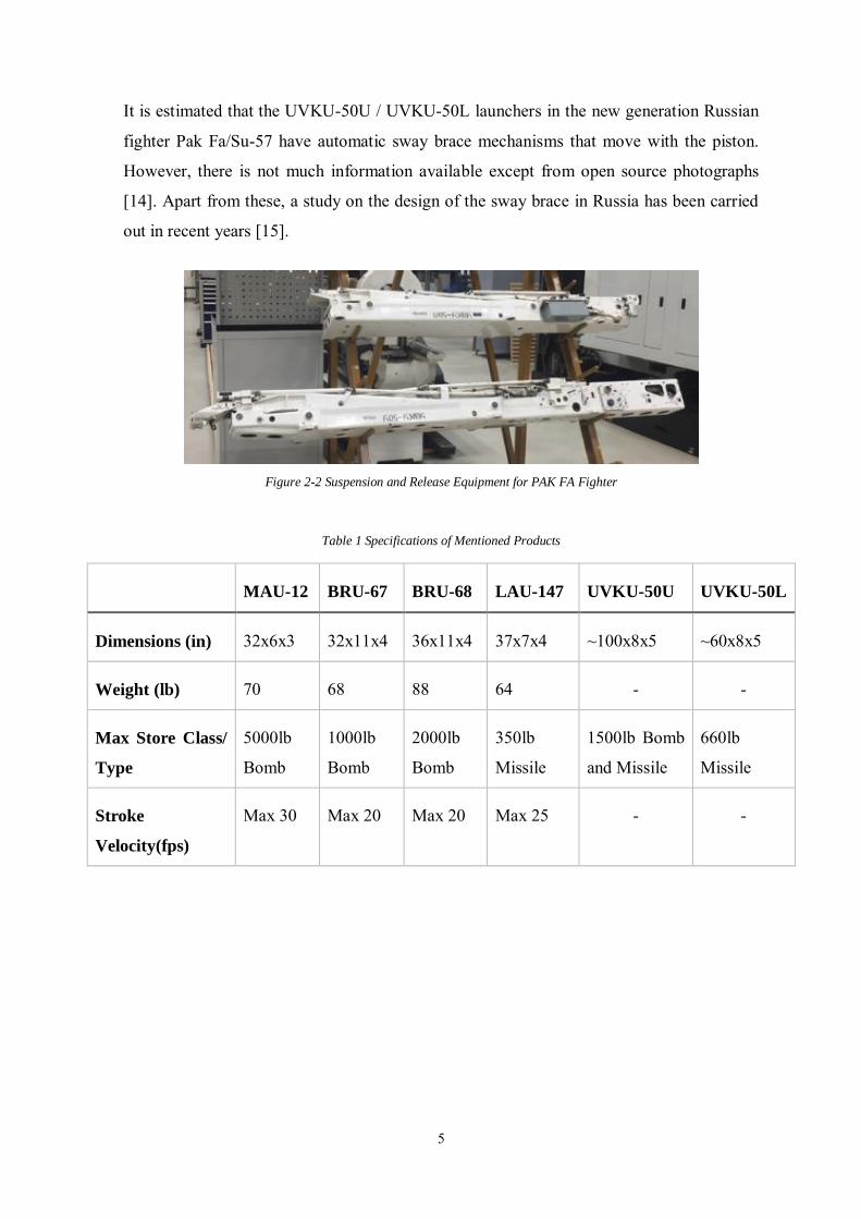
It is estimated that the UVKU-50U / UVKU-50L launchers in the new generation Russian
fighter Pak Fa/Su-57 have automatic sway brace mechanisms that move with the piston.
However, there is not much information available except from open source photographs
[14]. Apart from these, a study on the design of the sway brace in Russia has been carried
out in recent years [15].
Figure 2-2 Suspension and Release Equipment for PAK FA Fighter
Table 1 Specifications of Mentioned Products
MAU-12 BRU-67 BRU-68 LAU-147 UVKU-50U UVKU-50L
Dimensions (in) 32x6x3 32x11x4 36x11x4 37x7x4 ~100x8x5 ~60x8x5
Weight (lb) 70 68 88 64 - -
Max Store Class/
Type
5000lb
Bomb
1000lb
Bomb
2000lb
Bomb
350lb
Missile
1500lb Bomb
and Missile
660lb
Missile
Stroke
Velocity(fps)
Max 30 Max 20 Max 20 Max 25 - -
6
Purchase of the mentioned sample suspension and release equipment are not possible for
confidentiality reasons. These technologies are developed within the competence of each
country. Beyond these issues, at the point of using indigenous weapons in a locally
developed fighter aircraft, a suspension and release equipment design that can withstand the
mentioned conditions is a necessity in terms of independence of the defence industry and it
has to be carried out and developed together with major projects. Within the scope of the
thesis, it is important to work in terms of being a forward-looking project that we can use in
possible national fighter aircrafts, which designed, with national and domestic facilities in
our country.
2.2 Literature of Aircraft Weapons
There are many air to air and air to surface weapons, which used in fighter aircrafts. The
aircraft's mission profiles determine which weapon to carry. There are major popular
weapons and related studies in the literature used by NATO countries. In our country, it is
known that these missiles and bombs are in the inventory. In this section, firstly, the past
studies about weapons will be mentioned and then the used weapons will be discussed in
detail. The reason for this is that these weapons will be mentioned frequently during the
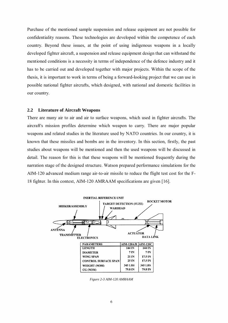
narration stage of the designed structure. Watson prepared performance simulations for the
AIM-120 advanced medium range air-to-air missile to reduce the flight test cost for the F-
18 fighter. In this context, AIM-120 AMRAAM specifications are given [16].
Figure 2-3 AIM-120 AMRAAM
7
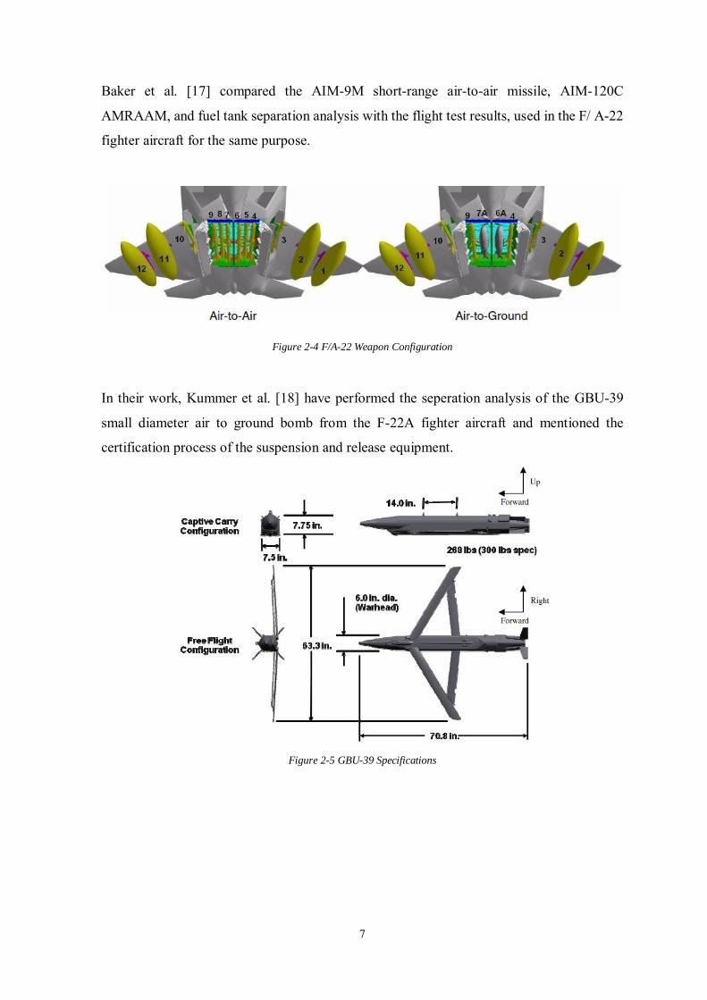
Baker et al. [17] compared the AIM-9M short-range air-to-air missile, AIM-120C
AMRAAM, and fuel tank separation analysis with the flight test results, used in the F/ A-22
fighter aircraft for the same purpose.
Figure 2-4 F/A-22 Weapon Configuration
In their work, Kummer et al. [18] have performed the seperation analysis of the GBU-39
small diameter air to ground bomb from the F-22A fighter aircraft and mentioned the
certification process of the suspension and release equipment.
Figure 2-5 GBU-39 Specifications
8
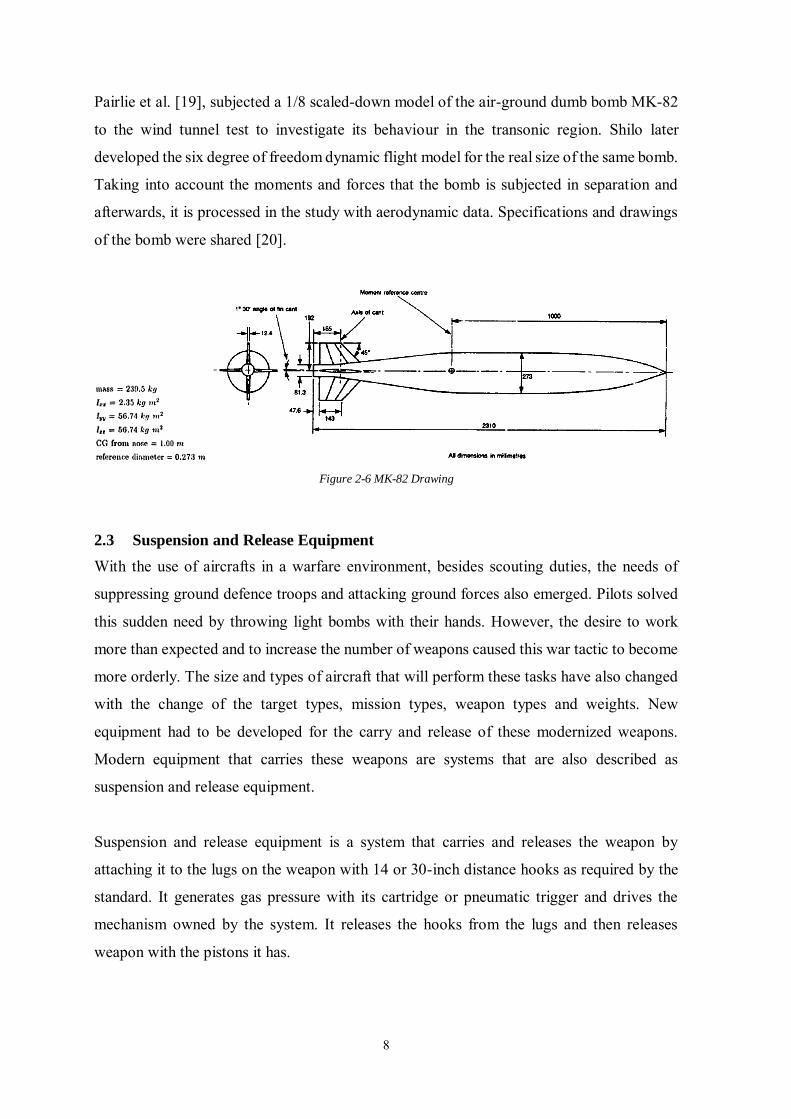
Pairlie et al. [19], subjected a 1/8 scaled-down model of the air-ground dumb bomb MK-82
to the wind tunnel test to investigate its behaviour in the transonic region. Shilo later
developed the six degree of freedom dynamic flight model for the real size of the same bomb.
Taking into account the moments and forces that the bomb is subjected in separation and
afterwards, it is processed in the study with aerodynamic data. Specifications and drawings
of the bomb were shared [20].
Figure 2-6 MK-82 Drawing
2.3 Suspension and Release Equipment
With the use of aircrafts in a warfare environment, besides scouting duties, the needs of
suppressing ground defence troops and attacking ground forces also emerged. Pilots solved
this sudden need by throwing light bombs with their hands. However, the desire to work
more than expected and to increase the number of weapons caused this war tactic to become
more orderly. The size and types of aircraft that will perform these tasks have also changed
with the change of the target types, mission types, weapon types and weights. New
equipment had to be developed for the carry and release of these modernized weapons.
Modern equipment that carries these weapons are systems that are also described as
suspension and release equipment.
Suspension and release equipment is a system that carries and releases the weapon by
attaching it to the lugs on the weapon with 14 or 30-inch distance hooks as required by the
standard. It generates gas pressure with its cartridge or pneumatic trigger and drives the
mechanism owned by the system. It releases the hooks from the lugs and then releases
weapon with the pistons it has.
9
Suspension and release equipment in today's technology are used on attack helicopters, light
attack aircraft, heavy bombers and combat aircraft. The most important criterion that is taken
into consideration when designing these systems is the weight of the carried equipment.
Initially, only the method of storing and releasing a large number of bombs caused the need
for an internal weapon bay. However, over time, the method of carrying these weapons in
internal bays has emerged with the increase of supersonic aircrafts and importance of low
visibility.
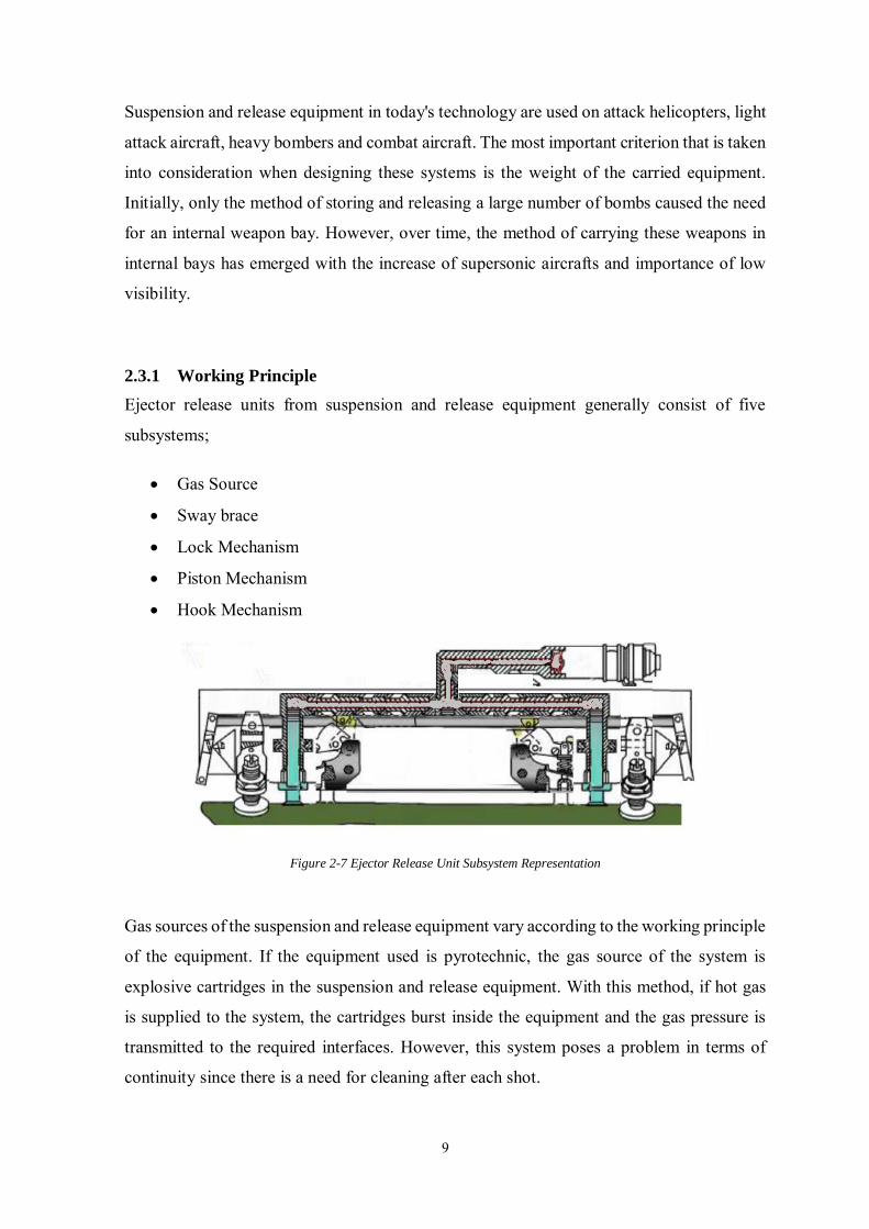
2.3.1 Working Principle
Ejector release units from suspension and release equipment generally consist of five
subsystems;
Gas Source
Sway brace
Lock Mechanism
Piston Mechanism
Hook Mechanism
Figure 2-7 Ejector Release Unit Subsystem Representation
Gas sources of the suspension and release equipment vary according to the working principle
of the equipment. If the equipment used is pyrotechnic, the gas source of the system is
explosive cartridges in the suspension and release equipment. With this method, if hot gas
is supplied to the system, the cartridges burst inside the equipment and the gas pressure is
transmitted to the required interfaces. However, this system poses a problem in terms of
continuity since there is a need for cleaning after each shot.
10
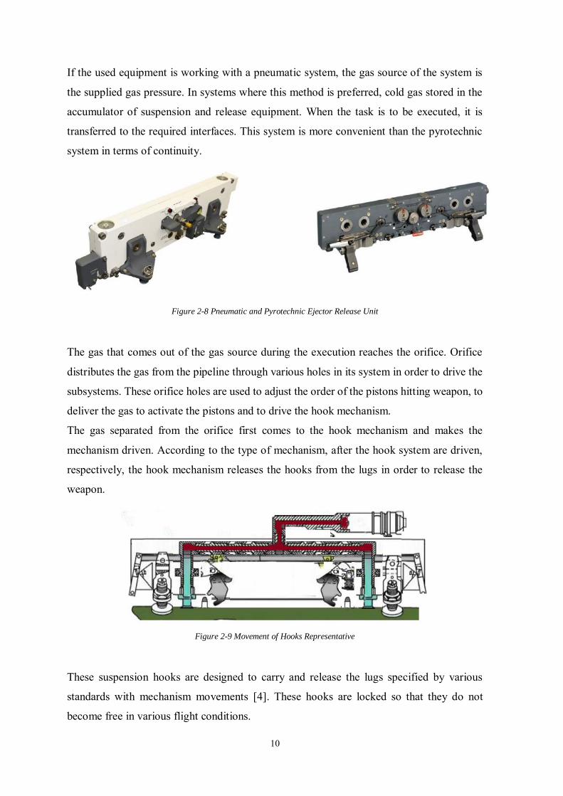
If the used equipment is working with a pneumatic system, the gas source of the system is
the supplied gas pressure. In systems where this method is preferred, cold gas stored in the
accumulator of suspension and release equipment. When the task is to be executed, it is
transferred to the required interfaces. This system is more convenient than the pyrotechnic
system in terms of continuity.
Figure 2-8 Pneumatic and Pyrotechnic Ejector Release Unit
The gas that comes out of the gas source during the execution reaches the orifice. Orifice
distributes the gas from the pipeline through various holes in its system in order to drive the
subsystems. These orifice holes are used to adjust the order of the pistons hitting weapon, to
deliver the gas to activate the pistons and to drive the hook mechanism.
The gas separated from the orifice first comes to the hook mechanism and makes the
mechanism driven. According to the type of mechanism, after the hook system are driven,
respectively, the hook mechanism releases the hooks from the lugs in order to release the
weapon.
Figure 2-9 Movement of Hooks Representative
These suspension hooks are designed to carry and release the lugs specified by various
standards with mechanism movements [4]. These hooks are locked so that they do not
become free in various flight conditions.
11
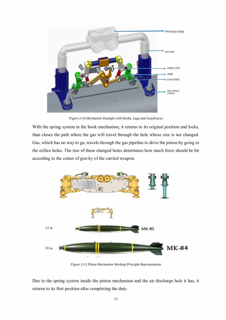
Figure 2-10 Mechanism Example with Hooks, Lugs and Swaybraces
With the spring system in the hook mechanism, it returns to its original position and locks,
than closes the path where the gas will travel through the hole whose size is not changed.
Gas, which has no way to go, travels through the gas pipeline to drive the piston by going to
the orifice holes. The size of these changed holes determines how much force should be hit
according to the center of gravity of the carried weapon.
Figure 2-11 Piston Mechanism Working Principle Representation
Due to the spring system inside the piston mechanism and the air discharge hole it has, it
returns to its first position after completing the duty.
12
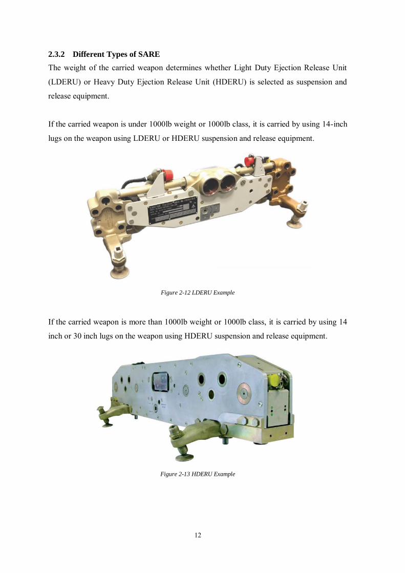
2.3.2 Different Types of SARE
The weight of the carried weapon determines whether Light Duty Ejection Release Unit
(LDERU) or Heavy Duty Ejection Release Unit (HDERU) is selected as suspension and
release equipment.
If the carried weapon is under 1000lb weight or 1000lb class, it is carried by using 14-inch
lugs on the weapon using LDERU or HDERU suspension and release equipment.
Figure 2-12 LDERU Example
If the carried weapon is more than 1000lb weight or 1000lb class, it is carried by using 14
inch or 30 inch lugs on the weapon using HDERU suspension and release equipment.
Figure 2-13 HDERU Example
13
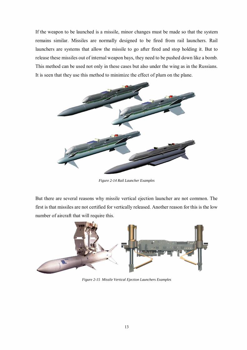
If the weapon to be launched is a missile, minor changes must be made so that the system
remains similar. Missiles are normally designed to be fired from rail launchers. Rail
launchers are systems that allow the missile to go after fired and stop holding it. But to
release these missiles out of internal weapon bays, they need to be pushed down like a bomb.
This method can be used not only in these cases but also under the wing as in the Russians.
It is seen that they use this method to minimize the effect of plum on the plane.
Figure 2-14 Rail Launcher Examples
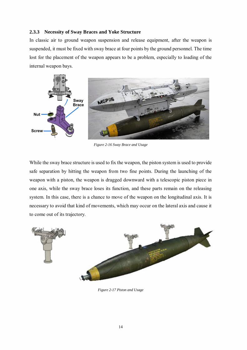
But there are several reasons why missile vertical ejection launcher are not common. The
first is that missiles are not certified for vertically released. Another reason for this is the low
number of aircraft that will require this.
Figure 2-15 Missile Vertical Ejection Launchers Examples
14
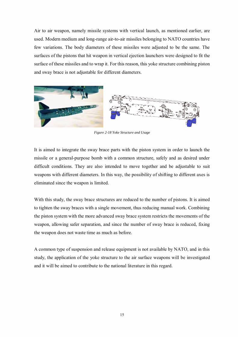
2.3.3 Necessity of Sway Braces and Yoke Structure
In classic air to ground weapon suspension and release equipment, after the weapon is
suspended, it must be fixed with sway brace at four points by the ground personnel. The time
lost for the placement of the weapon appears to be a problem, especially to loading of the
internal weapon bays.
Figure 2-16 Sway Brace and Usage
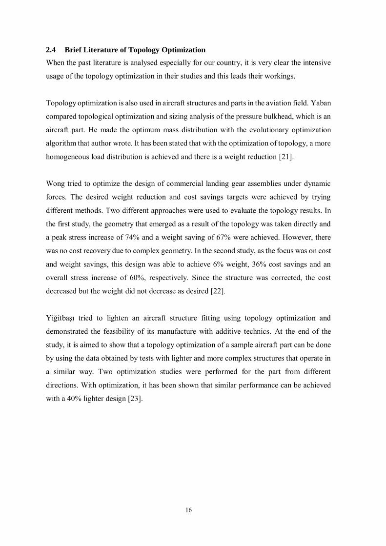
While the sway brace structure is used to fix the weapon, the piston system is used to provide
safe separation by hitting the weapon from two fine points. During the launching of the
weapon with a piston, the weapon is dragged downward with a telescopic piston piece in
one axis, while the sway brace loses its function, and these parts remain on the releasing
system. In this case, there is a chance to move of the weapon on the longitudinal axis. It is
necessary to avoid that kind of movements, which may occur on the lateral axis and cause it
to come out of its trajectory.
Figure 2-17 Piston and Usage
15
Air to air weapon, namely missile systems with vertical launch, as mentioned earlier, are
used. Modern medium and long-range air-to-air missiles belonging to NATO countries have
few variations. The body diameters of these missiles were adjusted to be the same. The
surfaces of the pistons that hit weapon in vertical ejection launchers were designed to fit the
surface of these missiles and to wrap it. For this reason, this yoke structure combining piston
and sway brace is not adjustable for different diameters.
Figure 2-18 Yoke Structure and Usage
It is aimed to integrate the sway brace parts with the piston system in order to launch the
missile or a general-purpose bomb with a common structure, safely and as desired under
difficult conditions. They are also intended to move together and be adjustable to suit
weapons with different diameters. In this way, the possibility of shifting to different axes is
eliminated since the weapon is limited.
With this study, the sway brace structures are reduced to the number of pistons. It is aimed
to tighten the sway braces with a single movement, thus reducing manual work. Combining
the piston system with the more advanced sway brace system restricts the movements of the
weapon, allowing safer separation, and since the number of sway brace is reduced, fixing
the weapon does not waste time as much as before.
A common type of suspension and release equipment is not available by NATO, and in this
study, the application of the yoke structure to the air surface weapons will be investigated
and it will be aimed to contribute to the national literature in this regard.
16
2.4 Brief Literature of Topology Optimization
When the past literature is analysed especially for our country, it is very clear the intensive
usage of the topology optimization in their studies and this leads their workings.
Topology optimization is also used in aircraft structures and parts in the aviation field. Yaban
compared topological optimization and sizing analysis of the pressure bulkhead, which is an
aircraft part. He made the optimum mass distribution with the evolutionary optimization
algorithm that author wrote. It has been stated that with the optimization of topology, a more
homogeneous load distribution is achieved and there is a weight reduction [21].
Wong tried to optimize the design of commercial landing gear assemblies under dynamic
forces. The desired weight reduction and cost savings targets were achieved by trying
different methods. Two different approaches were used to evaluate the topology results. In
the first study, the geometry that emerged as a result of the topology was taken directly and
a peak stress increase of 74% and a weight saving of 67% were achieved. However, there
was no cost recovery due to complex geometry. In the second study, as the focus was on cost
and weight savings, this design was able to achieve 6% weight, 36% cost savings and an
overall stress increase of 60%, respectively. Since the structure was corrected, the cost
decreased but the weight did not decrease as desired [22].
Yiğitbaşı tried to lighten an aircraft structure fitting using topology optimization and
demonstrated the feasibility of its manufacture with additive technics. At the end of the
study, it is aimed to show that a topology optimization of a sample aircraft part can be done
by using the data obtained by tests with lighter and more complex structures that operate in
a similar way. Two optimization studies were performed for the part from different
directions. With optimization, it has been shown that similar performance can be achieved
with a 40% lighter design [23].
17
Tamkan aimed to reduce the boarding step to the optimum weight by using different
materials and including the effect of the Lattice structure. The importance of reducing weight
and cost in the aviation industry was emphasized in this study and the idea that new
production techniques paved the way for optimization studies was advocated. As a result of
the study, it was seen that the designs that were optimized and the existing structures were
compared and success was achieved. It is concluded that the lattice design provides 46%
lighter than aluminum design and 3% lighter than 3D woven design, while discharging the
same performance requirements [24].
Erol worked to lighten the upper torque arm of the landing gear of a designated large body
aircraft using topology optimization. As safety is one of the important issues in the aviation
field, it is concluded that the optimized part is mitigated by examining the forces acting on
the torque arm at selected high loads. After the verification analysis of the geometry formed
after optimization was completed in Solidworks and sT Inspire, two designs with 22.95%
and 41.8% gain were obtained, respectively. It is stated that the road followed within the
scope of the study can be followed in many systems, especially aircrafts [25].
There are many studies on vehicle structural parts in literature. In his study, Işık included
topology optimization of the flange yoke structure that provides the connection in the cardan
shafts. An analysis model has been created by using the analysis methods of the existing part
and a similar forked flange part on the market, design variables and boundary conditions
have been determined. Based on the resulting topology, the new geometry of the forked
flange part was modelled and the production of the new forked flange geometry was
confirmed. As a result of topology optimization, it was stated that the weight of the structure
was reduced by around 12% [26].
Hatipoğlu discussed the optimization of the compressor bracket that one of engine elements
with OptiStruct software. The aim is to provide the targeted frequency value and reduce the
mass. In order to get more real results, the mesh model of the engine was created and placed
in the analysis in the same way to the bracket. Stress analysis was made and interpreted using
the HyperWorks program. The forces coming in case of maximum loading, taking 60%
smaller than the material’s yield value, were taken into consideration. As a result of the
analysis, the desired maximum value was found as 51 MPa and it was found that it was
18
approximately 35% less than the desired value. Because of the optimization, the targets were
met and it was stated that it would be possible to start mass production in the future [27].
Polavarapu worked at the automotive front seat backrest frame and its compliance with legal
standards and resistance to forces that may occur during an accident with its topology
optimization. The most appropriate strength rib positioning was performed under multiple
load conditions and as a result, it was stated that there was an average reduction in weight
of 12.95 percent [28].
Çalışkan, made an optimization work on the leaf spring bracket used in a commercial
vehicle. The part is intended to meet the specified structural strength criteria. While trying
to keep the hardness values constant, the weight was reduced and fatigue analysis was
successfully provided. Due to manufacturing constraints, 3 different designs have been
studied. In terms of geometry, different alternatives have been created such that the lightest
and most manufacturable design, the design that occurs after the displacement constraint is
added, and the final design, which is an extra lightened version of the second design. It is
stated that the final design is 18.25% lighter than the current design [29].
Enginar, has decided to replace a specified vehicle rim used in many vehicles as a result of
shape and topology optimization. The maximum stress value was reduced by 23 MPa,
resulting in a 5.7% gain, which is predicted to significantly increase the life time. The weight
value was reduced by 0.46 kg, resulting in a gain of 2.7%, which is said to contribute
positively to the raw material cost. Because of reaching the weight and maximum stress
values of the models, the optimum design that provides the desired fatigue tests has emerged
[30].
19
3 THEORY
3.1 Load Calculation for Aircraft Equipment
The critical issue in the design of the sway brace is the safe carriage than safe separation. It
is necessary to calculate which forces and moments our design should be based on. It
provides information about how much force is applied to the weapon with different
maneuvers with the desired dimensions, and the forces acting on these structural parts. For
this purpose, MIL-STD-2088B BRU and MIL-STD-8591 aircraft-weapon interface and
methods in the standard were applied respectively in this study [31] [32].
The inertial force and maximum reaction force calculations in the appendixes of the MIL-
STD-8591H version have been used in some aspects by being enriched in today's conditions.
For this purpose, firstly using the FORTRAN program and then MATLAB, calculations are
made with the following equations, and the reaction forces occurring in various maneuver
and motion situations can be listed.
When calculating reaction forces, the forces are calculated on two main headings as inertial
load and aerodynamic load. During the movements of the aircraft, both inertial movements
and aerodynamic forces arise from contact with air. Although the validity of the calculation
methods of aerodynamic forces used in the standards can be used at the time they are written,
the need to be updated in the current situation has emerged. For this purpose, aerodynamic
calculations will be made more realistic in terms of today's fighter aircraft, as used in the
following documents. The scope of the study has been determined with some limitations and
acceptances.
Physical characteristics in the study are important values for calculating the desired values.
A flexible use can be achieved by using the features of parametric aircraft and suspension
and release systems. Thus, when necessary, the forces required for different aircraft and
fighter systems can be calculated. In this study, the information of the generically named
systems was taken from a reliable open source, then verified by the Aircraft Stores Interface
Manual (ASIM) reference, it will not be shared directly [33].
20
Inertial Loads are the subject that should be handled first within the scope of the study. The
weight of the weapon to be carried, the location of weapon on aircraft and the performance
of the aircraft are the parameters affecting the inertial loads. In this context, the maneuver
the aircraft is doing within the scope of the operational action plan directly affects the load
values to be calculated. These maneuvers are summarized as high-level flight, arrested,
landing and catapulting, and the critical loads that will occur in the CG of the weapon are
mentioned separately. Load factor envelopes are limited to the latest version of the 8591
standard.
In this thesis, the weapon considered for the internal weapon bay has been taken into
consideration. The aerodynamic load effects arising from the contact of air on the aircraft
with during maneuvers should be considered as another study item. In addition, the irregular
situation due to cavity problems during ejection from weapon bay was also left within the
scope of the study. The movements that come from the standard and that the aircraft performs
in certain maneuvers are directly used within the scope of the thesis. However, the
calculation of the aerodynamic loads effect from similar studies in terms of similar surfaces
of the weapon will be done anyway as mentioned and will be added if it is observed to have
made a serious change.
3.1.1 Physical Characteristics for Store
With the information-sharing platform called ASIM, a wide range of information is shared
within the scope of weapon, suspension and release systems and aircrafts used by NATO
countries. The weights of the weapon, the mass moments of inertia, the distances between
the sway braces of the generic systems to be used in the calculation of the forces, the distance
of the points where the weapon will be hung, to the CG of the weapon, the angle of the sway
braces with the aircraft obtained from these sources are compared and used. ASIM, which
is used as a reference to contribute to the work of cooperating countries within the scope of
aircraft-store integration, assists with new weapon, new suspension and release equipment
and new aircraft designs.
21
Table 2 Source of Specifications
Weight of store
ASIM,
Store Characteristics,
Bombs
Mass moment of inertia X-axis
Mass moment of inertia Y-axis
Mass moment of inertia Z-axis
Distance between lugs
ASIM,
Store Characteristics
and
Suspension Equipment
Distance store CG to fwd lug X-direction
Distance store CG to aft lug X-direction
Distance store CG to fwd lug Y-direction
Distance store CG to aft lug Y-direction
Distance store CG to fwd lug Z-direction
Distance store CG to aft lug Z-direction
Distance between forward and aft sway brace pads
Distance store CG to fwd sway brace pad X-direction
Distance si re CG to aft sway brace pad X-direction
Distance store CG to near sway brace pad Y-direction
Distance store CG to far sway brace pad Y-direction
Distance store CG to right sway brace pad Z-direction
Distance store CG to left sway brace pad Z-direction.
Angle between radius of curvature of store and Z-axis ASIM,
Suspension Equipment Rotation around the X-axis for stores mounted at a roll angle
W.R.T. the aircraft axis system.
3.1.2 Inertial Load Equations
Six acceleration and load value affecting the center of the weapon are found by ready values
of weapon and the generic aircraft, adding into the equations below. In this way, any desired
value can be found easily.
22
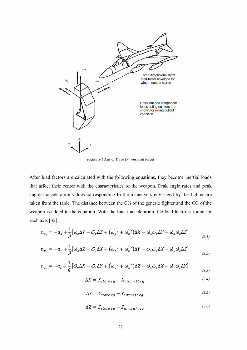
Figure 3-1 Axis of Three Dimensional Flight
After load factors are calculated with the following equations, they become inertial loads
that affect their center with the characteristics of the weapon. Peak angle rates and peak
angular acceleration values corresponding to the maneuvers envisaged by the fighter are
taken from the table. The distance between the CG of the generic fighter and the CG of the
weapon is added to the equation. With the linear acceleration, the load factor is found for
each axis [32].
𝑛𝑥𝑠= −𝑎𝑥 +
1
𝑔[𝜔𝑧̈ ∆𝑌 − 𝜔𝑦̈ ∆𝑍 + (𝜔𝑦
2̇ + 𝜔𝑧2̇ )∆𝑋 − 𝜔𝑥̇ 𝜔𝑦̇ ∆𝑌 − 𝜔𝑥̇ 𝜔𝑧̇ ∆𝑍]
(3.1)
𝑛𝑦𝑠= −𝑎𝑦 +
1
𝑔[𝜔𝑥̈ ∆𝑍 − 𝜔𝑧̈ ∆𝑋 + (𝜔𝑥
2̇ + 𝜔𝑧2̇ )∆𝑌 − 𝜔𝑥̇ 𝜔𝑦̇ ∆𝑋 − 𝜔𝑦̇ 𝜔𝑧̇ ∆𝑍]
(3.2)
𝑛𝑧𝑠= −𝑎𝑧 +
1
𝑔[𝜔𝑦̈ ∆𝑋 − 𝜔𝑥̈ ∆𝑌 + (𝜔𝑦
2̇ + 𝜔𝑥2̇ )∆𝑍 − 𝜔𝑥̇ 𝜔𝑧̇ ∆𝑋 − 𝜔𝑦̇ 𝜔𝑧̇ ∆𝑌]
(3.3)
∆𝑋 = 𝑋𝑠𝑡𝑜𝑟𝑒 𝑐𝑔 − 𝑋𝑎𝑖𝑟𝑐𝑟𝑎𝑓𝑡 𝑐𝑔 (3.4)
∆𝑌 = 𝑌𝑠𝑡𝑜𝑟𝑒 𝑐𝑔 − 𝑌𝑎𝑖𝑟𝑐𝑟𝑎𝑓𝑡 𝑐𝑔 (3.5)
∆𝑍 = 𝑍𝑠𝑡𝑜𝑟𝑒 𝑐𝑔 − 𝑍𝑎𝑖𝑟𝑐𝑟𝑎𝑓𝑡 𝑐𝑔 (3.6)
23
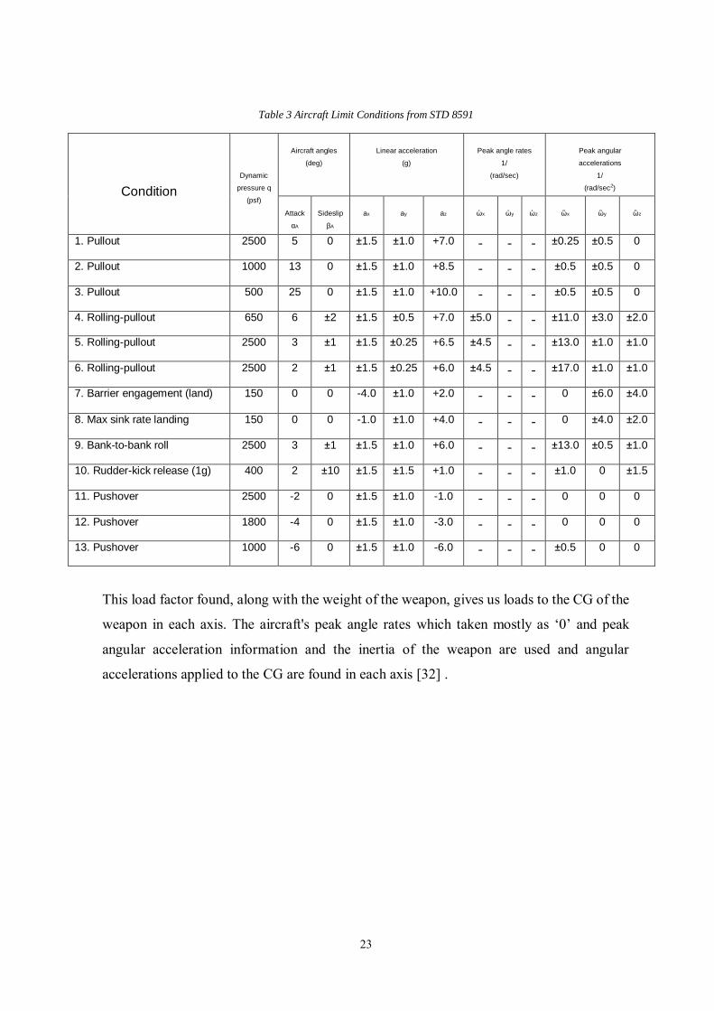
Table 3 Aircraft Limit Conditions from STD 8591
Condition
Dynamic
pressure q
(psf)
Aircraft angles
(deg)
Linear acceleration
(g)
Peak angle rates
1/
(rad/sec)
Peak angular
accelerations
1/
(rad/sec2)
Attack
αA
Sideslip
βA
ax
ay
az
ὡx
ὡy
ὡz
ὣx
ὣy
ὣz
1. Pullout 2500 5 0 ±1.5 ±1.0 +7.0 - - - ±0.25 ±0.5 0
2. Pullout 1000 13 0 ±1.5 ±1.0 +8.5 - - - ±0.5 ±0.5 0
3. Pullout 500 25 0 ±1.5 ±1.0 +10.0 - - - ±0.5 ±0.5 0
4. Rolling-pullout 650 6 ±2 ±1.5 ±0.5 +7.0 ±5.0 - - ±11.0 ±3.0 ±2.0
5. Rolling-pullout 2500 3 ±1 ±1.5 ±0.25 +6.5 ±4.5 - - ±13.0 ±1.0 ±1.0
6. Rolling-pullout 2500 2 ±1 ±1.5 ±0.25 +6.0 ±4.5 - - ±17.0 ±1.0 ±1.0
7. Barrier engagement (land) 150 0 0 -4.0 ±1.0 +2.0 - - - 0 ±6.0 ±4.0
8. Max sink rate landing 150 0 0 -1.0 ±1.0 +4.0 - - - 0 ±4.0 ±2.0
9. Bank-to-bank roll 2500 3 ±1 ±1.5 ±1.0 +6.0 - - - ±13.0 ±0.5 ±1.0
10. Rudder-kick release (1g) 400 2 ±10 ±1.5 ±1.5 +1.0 - - - ±1.0 0 ±1.5
11. Pushover 2500 -2 0 ±1.5 ±1.0 -1.0 - - - 0 0 0
12. Pushover 1800 -4 0 ±1.5 ±1.0 -3.0 - - - 0 0 0
13. Pushover 1000 -6 0 ±1.5 ±1.0 -6.0 - - - ±0.5 0 0
This load factor found, along with the weight of the weapon, gives us loads to the CG of the
weapon in each axis. The aircraft's peak angle rates which taken mostly as ‘0’ and peak
angular acceleration information and the inertia of the weapon are used and angular
accelerations applied to the CG are found in each axis [32] .
24
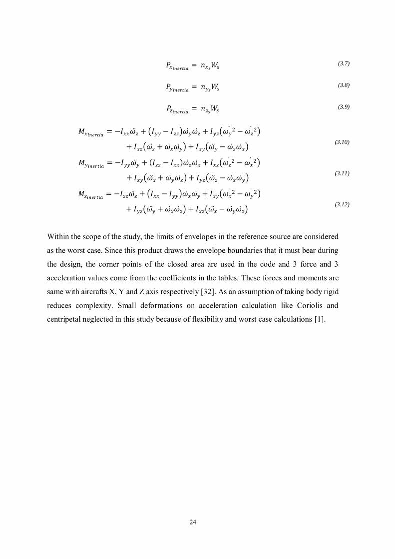
𝑃𝑥𝑖𝑛𝑒𝑟𝑡𝑖𝑎
= 𝑛𝑥𝑠𝑊𝑠 (3.7)
𝑃𝑦𝑖𝑛𝑒𝑟𝑡𝑖𝑎
= 𝑛𝑦𝑠𝑊𝑠 (3.8)
𝑃𝑧𝑖𝑛𝑒𝑟𝑡𝑖𝑎
= 𝑛𝑧𝑠𝑊𝑠 (3.9)
𝑀𝑥𝑖𝑛𝑒𝑟𝑡𝑖𝑎= −𝐼𝑥𝑥𝜔𝑧̈ + (𝐼𝑦𝑦 − 𝐼𝑧𝑧)𝜔𝑦̇ 𝜔𝑧̇ + 𝐼𝑦𝑧(𝜔𝑦
2̇ − 𝜔𝑧2̇ )
+ 𝐼𝑥𝑧(𝜔𝑧̈ + 𝜔𝑥̇ 𝜔𝑦̇ ) + 𝐼𝑥𝑦(𝜔𝑦̈ − 𝜔𝑧̇ 𝜔𝑥̇ )
(3.10)
𝑀𝑦𝑖𝑛𝑒𝑟𝑡𝑖𝑎= −𝐼𝑦𝑦𝜔𝑦̈ + (𝐼𝑧𝑧 − 𝐼𝑥𝑥)𝜔𝑧̇ 𝜔𝑥̇ + 𝐼𝑥𝑧(𝜔𝑧
2̇ − 𝜔𝑥2̇ )
+ 𝐼𝑥𝑦(𝜔𝑥̈ + 𝜔𝑦̇ 𝜔𝑧̇ ) + 𝐼𝑦𝑧(𝜔𝑧̈ − 𝜔𝑥̇ 𝜔𝑦̇ )
(3.11)
𝑀𝑧𝑖𝑛𝑒𝑟𝑡𝑖𝑎= −𝐼𝑧𝑧𝜔𝑧̈ + (𝐼𝑥𝑥 − 𝐼𝑦𝑦)𝜔𝑥̇ 𝜔𝑦̇ + 𝐼𝑥𝑦(𝜔𝑥
2̇ − 𝜔𝑦2̇ )
+ 𝐼𝑦𝑧(𝜔𝑦̈ + 𝜔𝑥̇ 𝜔𝑧̇ ) + 𝐼𝑥𝑧(𝜔𝑥̈ − 𝜔𝑦̇ 𝜔𝑧̇ )
(3.12)
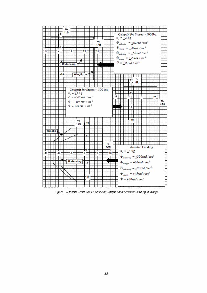
Within the scope of the study, the limits of envelopes in the reference source are considered
as the worst case. Since this product draws the envelope boundaries that it must bear during
the design, the corner points of the closed area are used in the code and 3 force and 3
acceleration values come from the coefficients in the tables. These forces and moments are
same with aircrafts X, Y and Z axis respectively [32]. As an assumption of taking body rigid
reduces complexity. Small deformations on acceleration calculation like Coriolis and
centripetal neglected in this study because of flexibility and worst case calculations [1].
25
Figure 3-2 Inertia Limit Load Factors of Catapult and Arrested Landing at Wings
26
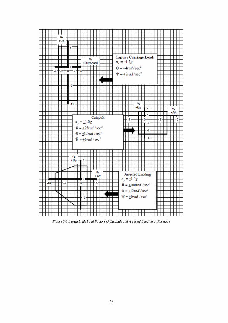
Figure 3-3 Inertia Limit Load Factors of Catapult and Arrested Landing at Fuselage
27
3.1.3 Aerodynamic Load Equations
Since aerodynamic forces are more complicated to calculate, many predictions have been
made on weapon. Although verification and correction studies have been performed with
flight tests and ground tests, taking realistic values requires precise work. The effects of
aerodynamic forces for the arrested landing, catapulting and flight situations mentioned were
evaluated. It has been observed in studies that the aerodynamic effect is negligible due to the
worst-case scenario in cases other than flight. In the case of flight, situations where the
aerodynamic force effect is high are not generally found in the most scenarios. Therefore, it
has been evaluated that there is no effect in calculating the max load, but it will be beneficial
to try to calculate it anyway.
Calculation equations of the angle of attack and sideslip of the aircraft in the load envelopes
are given. The required values are found by using the figure 4-2 and 4-3 if the aircraft type
is similar and by the table 3 according to the similarity of the detailed maneuvering
situations. It is stated in 8591 standard that realistic aerodynamic calculations should be
calculated in accordance with real flight and ground test data.
The aerodynamic loads mentioned consist of lift moment and drag forces. Due to the shape
and surfaces of the weapon, these forces also act on the plane. Lift and drag forces occur
around all axes around the aerodynamic center of the weapon, causing rotational acceleration
around CG. After the preliminary design, detailing the aerodynamic calculations becomes
more critical. The list of values required for performing the calculations mentioned in 8591H
is given below.
28
- Dynamic pressure
- Weapon Frontal Area
- Weapon Length
- Drag coefficient
- Weapon angle of sideslip
- Weapon angle of attack
- Lift coefficient slope
- Pitch moment coefficient
- Side force coefficient slope
- Yaw moment coefficient slope
Aiming to find flight data in the preliminary design process is an optimistic move. For this
reason, as mentioned before, calculation is started by selecting maneuvers in the corners of
the flight envelope, where angle of slip in and angle of attack are maximum. Dynamic
pressures are also among the values specific to these maneuvers. All the remaining
coefficients are found by comparing the weapon to a certain shape and using the generic
general coefficients of that shape, as specified.
Aerodynamic forces and moments are achieved by combining the coefficients taken from
references with weapon and data in maximum situations. The studies show that there is no
need to examine the flutter effect in carrying weapon lighter than 2000lb because of their
structural nonlinearities. Suspension and release equipment, weapon and the vibration values
of the pylon trio are therefore excluded and evaluated as an opportunity for future studies
[1].
29
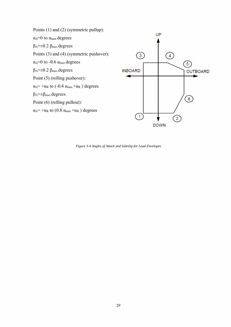
Points (1) and (2) (symmetric pullup):
αA=0 to αmax degrees
βA=±0.2 βmax degrees
Points (3) and (4) (symmetric pushover):
αA=0 to -0.6 αmax degrees
βA=±0.2 βmax degrees
Point (5) (rolling pushover):
αA= +αR to (-0.4 αmax +αR ) degrees
βA=±βmax degrees
Point (6) (rolling pullout):
αA= +αR to (0.8 αmax +αR ) degrees
Figure 3-4 Angles of Attack and Sideslip for Load Envelopes
30
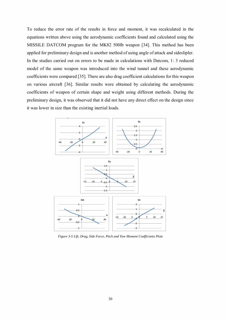
To reduce the error rate of the results in force and moment, it was recalculated in the
equations written above using the aerodynamic coefficients found and calculated using the
MISSILE DATCOM program for the MK82 500lb weapon [34]. This method has been
applied for preliminary design and is another method of using angle of attack and sideslipler.
In the studies carried out on errors to be made in calculations with Datcom, 1: 3 reduced
model of the same weapon was introduced into the wind tunnel and these aerodynamic
coefficients were compared [35]. There are also drag coefficient calculations for this weapon
on various aircraft [36]. Similar results were obtained by calculating the aerodynamic
coefficients of weapon of certain shape and weight using different methods. During the
preliminary design, it was observed that it did not have any direct effect on the design since
it was lower in size than the existing inertial loads.
Figure 3-5 Lift, Drag, Side Force, Pitch and Yaw Moment Coefficients Plots
31
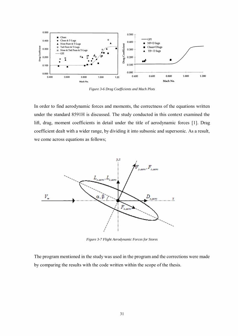
Figure 3-6 Drag Coefficients and Mach Plots
In order to find aerodynamic forces and moments, the correctness of the equations written
under the standard 8591H is discussed. The study conducted in this context examined the
lift, drag, moment coefficients in detail under the title of aerodynamic forces [1]. Drag
coefficient dealt with a wider range, by dividing it into subsonic and supersonic. As a result,
we come across equations as follows;
Figure 3-7 Flight Aerodynamic Forces for Stores
The program mentioned in the study was used in the program and the corrections were made
by comparing the results with the code written within the scope of the thesis.
32
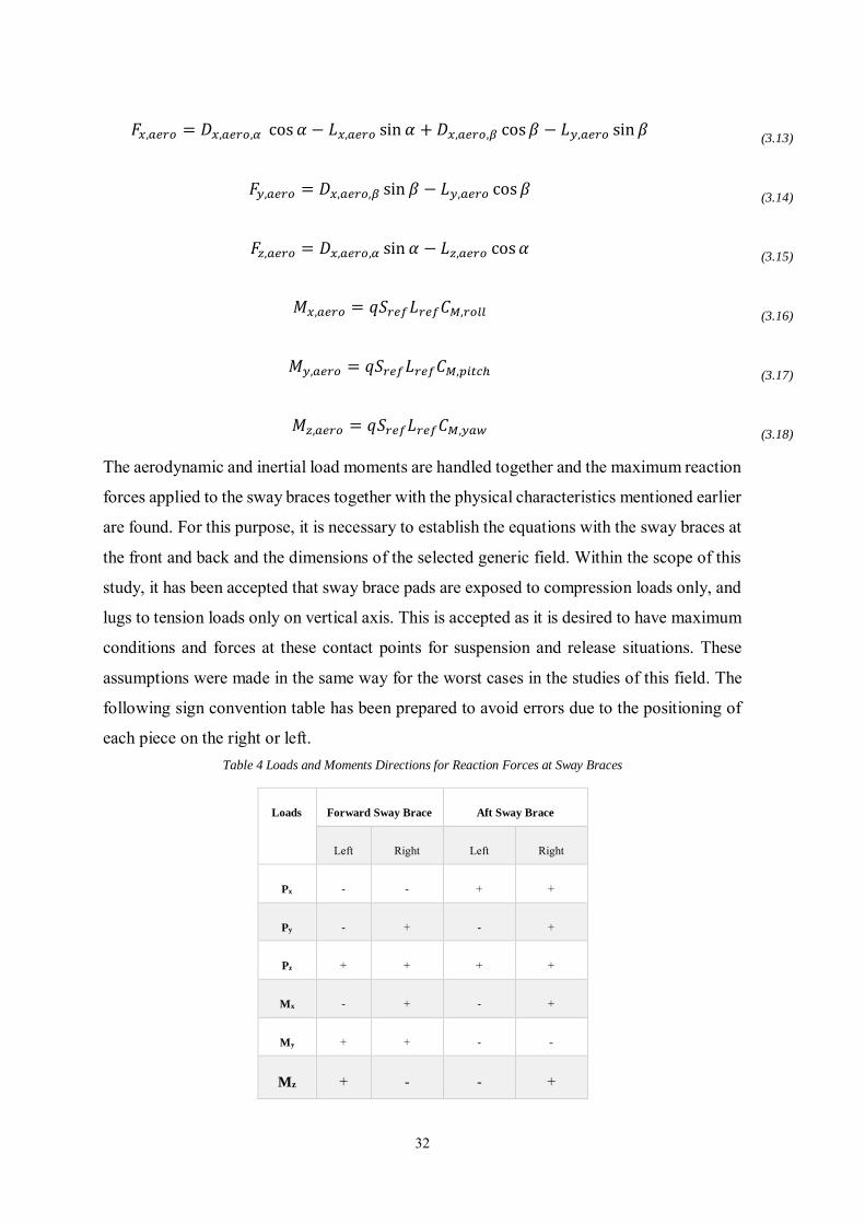
𝐹𝑥,𝑎𝑒𝑟𝑜 = 𝐷𝑥,𝑎𝑒𝑟𝑜,𝛼 cos 𝛼 − 𝐿𝑥,𝑎𝑒𝑟𝑜 sin 𝛼 + 𝐷𝑥,𝑎𝑒𝑟𝑜,𝛽 cos 𝛽 − 𝐿𝑦,𝑎𝑒𝑟𝑜 sin 𝛽
(3.13)
𝐹𝑦,𝑎𝑒𝑟𝑜 = 𝐷𝑥,𝑎𝑒𝑟𝑜,𝛽 sin 𝛽 − 𝐿𝑦,𝑎𝑒𝑟𝑜 cos 𝛽
(3.14)
𝐹𝑧,𝑎𝑒𝑟𝑜 = 𝐷𝑥,𝑎𝑒𝑟𝑜,𝛼 sin 𝛼 − 𝐿𝑧,𝑎𝑒𝑟𝑜 cos 𝛼
(3.15)
𝑀𝑥,𝑎𝑒𝑟𝑜 = 𝑞𝑆𝑟𝑒𝑓𝐿𝑟𝑒𝑓𝐶𝑀,𝑟𝑜𝑙𝑙
(3.16)
𝑀𝑦,𝑎𝑒𝑟𝑜 = 𝑞𝑆𝑟𝑒𝑓𝐿𝑟𝑒𝑓𝐶𝑀,𝑝𝑖𝑡𝑐ℎ
(3.17)
𝑀𝑧,𝑎𝑒𝑟𝑜 = 𝑞𝑆𝑟𝑒𝑓𝐿𝑟𝑒𝑓𝐶𝑀,𝑦𝑎𝑤
(3.18)
The aerodynamic and inertial load moments are handled together and the maximum reaction
forces applied to the sway braces together with the physical characteristics mentioned earlier
are found. For this purpose, it is necessary to establish the equations with the sway braces at
the front and back and the dimensions of the selected generic field. Within the scope of this
study, it has been accepted that sway brace pads are exposed to compression loads only, and
lugs to tension loads only on vertical axis. This is accepted as it is desired to have maximum
conditions and forces at these contact points for suspension and release situations. These
assumptions were made in the same way for the worst cases in the studies of this field. The
following sign convention table has been prepared to avoid errors due to the positioning of
each piece on the right or left. Table 4 Loads and Moments Directions for Reaction Forces at Sway Braces
Loads Forward Sway Brace Aft Sway Brace
Left Right Left Right
Px - - + +
Py - + - +
Pz + + + +
Mx - + - +
My + + - -
Mz + - - +
33
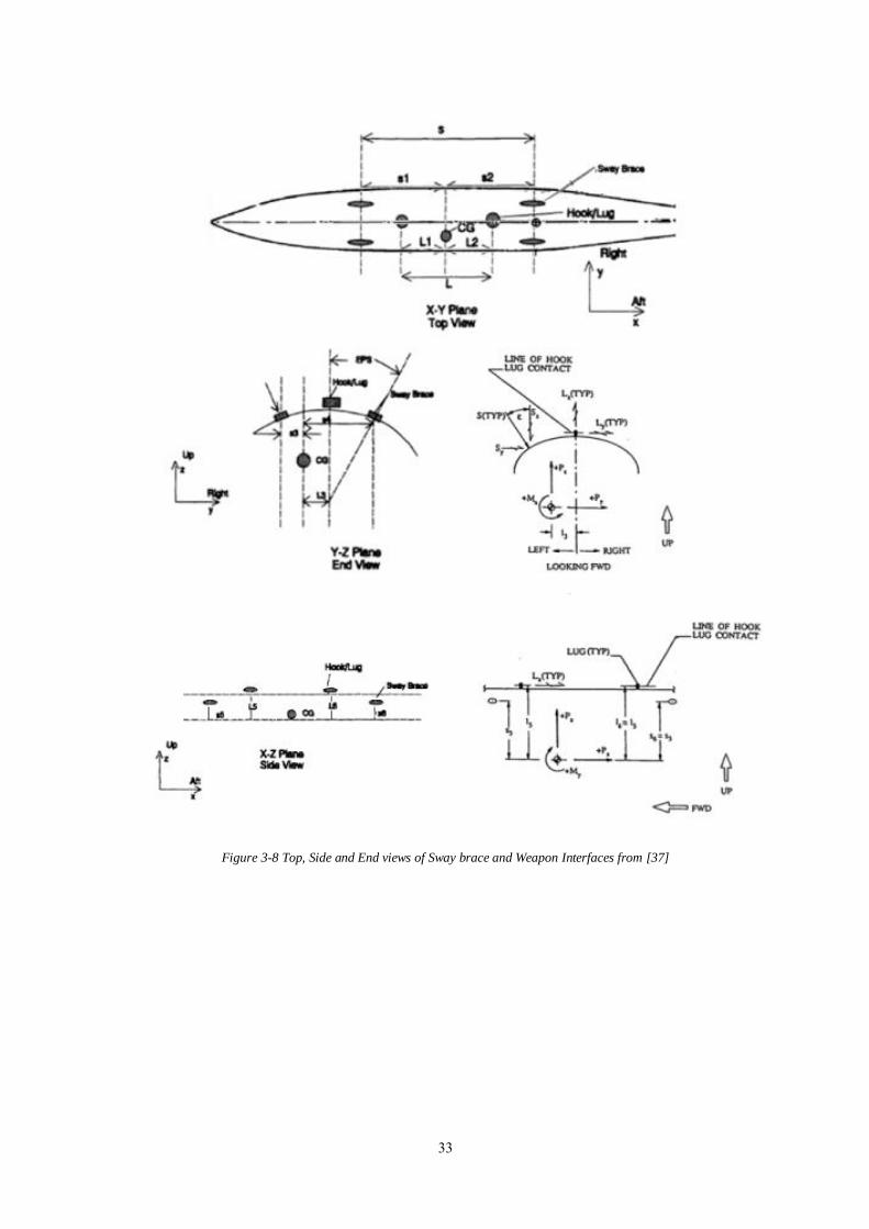
Figure 3-8 Top, Side and End views of Sway brace and Weapon Interfaces from [37]
34
As seen in the figures, the equations for front sway braces were established with free body
diagrams for every axis and related areas and the calculation was started [37]. The aim here
is to create an equation with the effects of forces and moments in various axes on the points
where the weapon is fixed. As shown above, a weapon on the equipment has four contact
points; two lugs and two swaybraces. The forces and moments coming to the center of the
weapon are reflected in the equation and shortened by using the distances to the mentioned
4 contact points.
𝑆𝑦 = 𝑆𝑧 tan 𝜀
(3.19)
𝑆𝑧2 + 𝑆𝑦
2 = 𝑆2
(3.20)
𝑆𝑧 = 𝐴𝑃𝑥 + 𝐵𝑃𝑦 + 𝐶𝑃𝑧 + 𝐷𝑀𝑥 + 𝐸𝑀𝑦 + 𝐹𝑀𝑧
(3.21)
𝑆 =
𝑆𝑧
cos 𝜀
(3.22)
𝐴 =
𝐿5
2(𝑆1 + 𝐿2)+
𝐿3
𝑆 tan 𝜀
(3.23)
𝐵 =
𝑆2𝐿5
𝑆𝐾
(3.24)
𝐶 =
𝑆2
𝑆(
1
2+
𝐿3
𝐾)
(3.25)
𝐷 =
𝑆2
𝑆𝐾
(3.26)
𝐸 =
1
2
1
(𝑆1 + 𝐿2)
(3.27)
𝐹 =
1
Stan 𝜀
(3.28)
𝐻 = (𝐿5 − 𝑆5) tan 𝜀
(3.29)
𝐾 = 𝐻 + 𝐿3 + 𝑆3
(3.30)
35
3.2 Force Calculation for Specific Weapon Release
The effects of weapon on CG due to inertial and aerodynamic forces during the maneuvers
performed by the fighter were evaluated in the previous section. The force required to
separate and remove the weapon from the releasing system is another determining value that
must be calculated to design the interface structure of the piston, which is the driving part of
the releasing system. When weapon is desired to be left in the air, this interface will be
subjected to the impact force and will do the fixing and dropping function together.
If weapon is to be ejected from a launcher that is not yet known, studies on a weapon whose
characteristics are known should be examined. In military academic articles, it is seen that
general-purpose bombs generally takes place in the aircraft-store interface studies. These
weapons are referred to as dumb bombs. Thanks to the target adjustments on the aircraft, the
distance to the target is carefully examined.
The critical factor in releasing from the suspension and release systems is the weight. It can
easily be said before the research that higher forces will be required to drop heavy weapon.
The important point here is that the weapon must come out at determined speeds to
effectively separate from the launcher. The connection of the weight with the force should
be considered with this detail.
The most accurate way to calculate an ejector release unit performance data is in-flight and
static ejection tests. However, since these methods are generally expensive, it is more logical
to use a performance estimation model that has been proven in previous studies, has been
corrected with flight and ground test data based on errors.
36
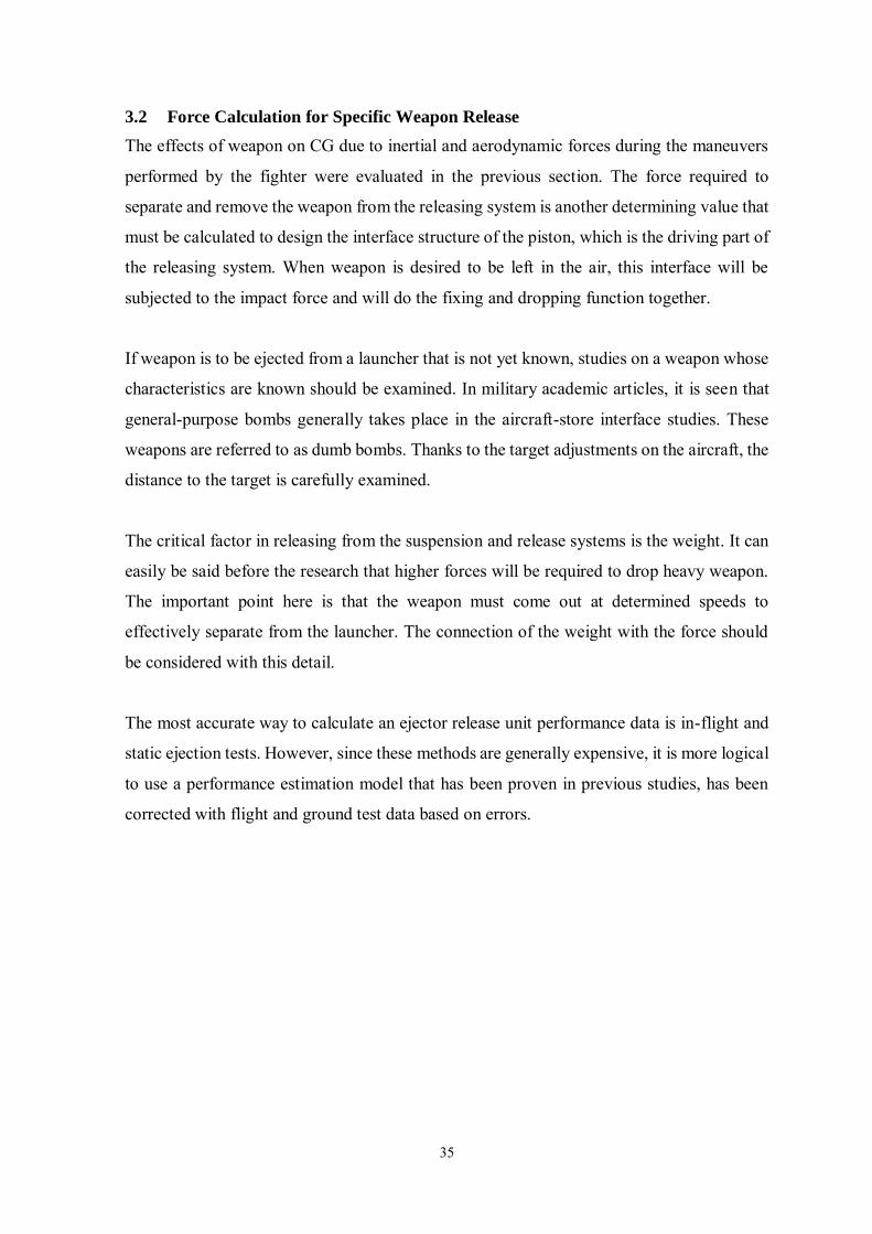
Figure 3-9 Mau-12 Ejector Release Unit
For this study, its use, reliability and performance have been demonstrated with many
documents, MAU-12 ejector release unit has been preferred, which is still in use by many
NATO countries. This was developed with the aim of carrying and ejecting weapon up to
5000lb. This ERU, known in operational terms, has been used directly in many combat
environments. It is known to be used in fighter aircraft such as F-4, F-15 and F-16. In this
suspension and release equipment, the electrically triggered cartridge explodes and the
mechanism is operated with hot gas pressure, i.e. it is pyrotechnic. This ERU, which is about
70 pounds, has a length of 32 inches, a height of 6.25 inches and a thickness of 3 inches.
If we had to drop the weapon from the MAU-12 ERU, it seems that it would be easier to
calculate what the force is required on normal flights. The force-time plot of the MAU-12
field with varying weights was shared in the study [6]. This graphic includes the initial firing,
releasing and calming process.
37
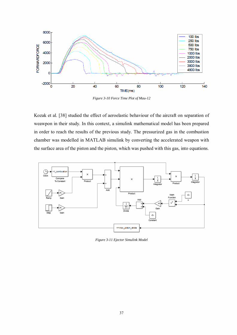
Figure 3-10 Force Time Plot of Mau-12
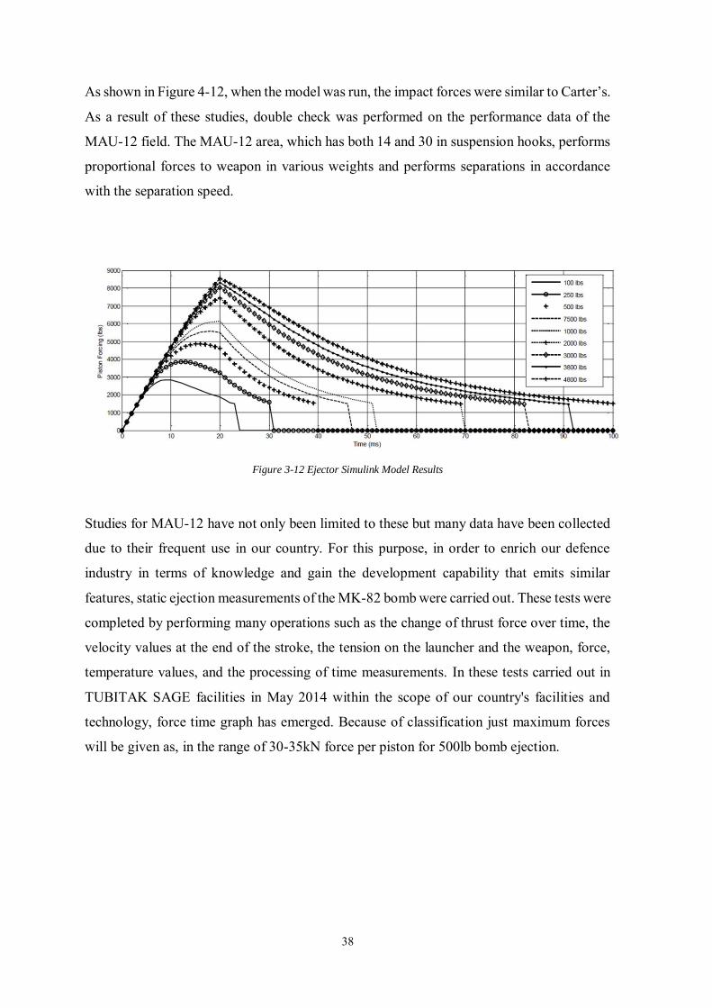
Kozak et al. [38] studied the effect of aeroelastic behaviour of the aircraft on separation of
weawpon in their study. In this context, a simulink mathematical model has been prepared
in order to reach the results of the previous study. The pressurized gas in the combustion
chamber was modelled in MATLAB simulink by converting the accelerated weapon with
the surface area of the piston and the piston, which was pushed with this gas, into equations.
Figure 3-11 Ejector Simulink Model
38
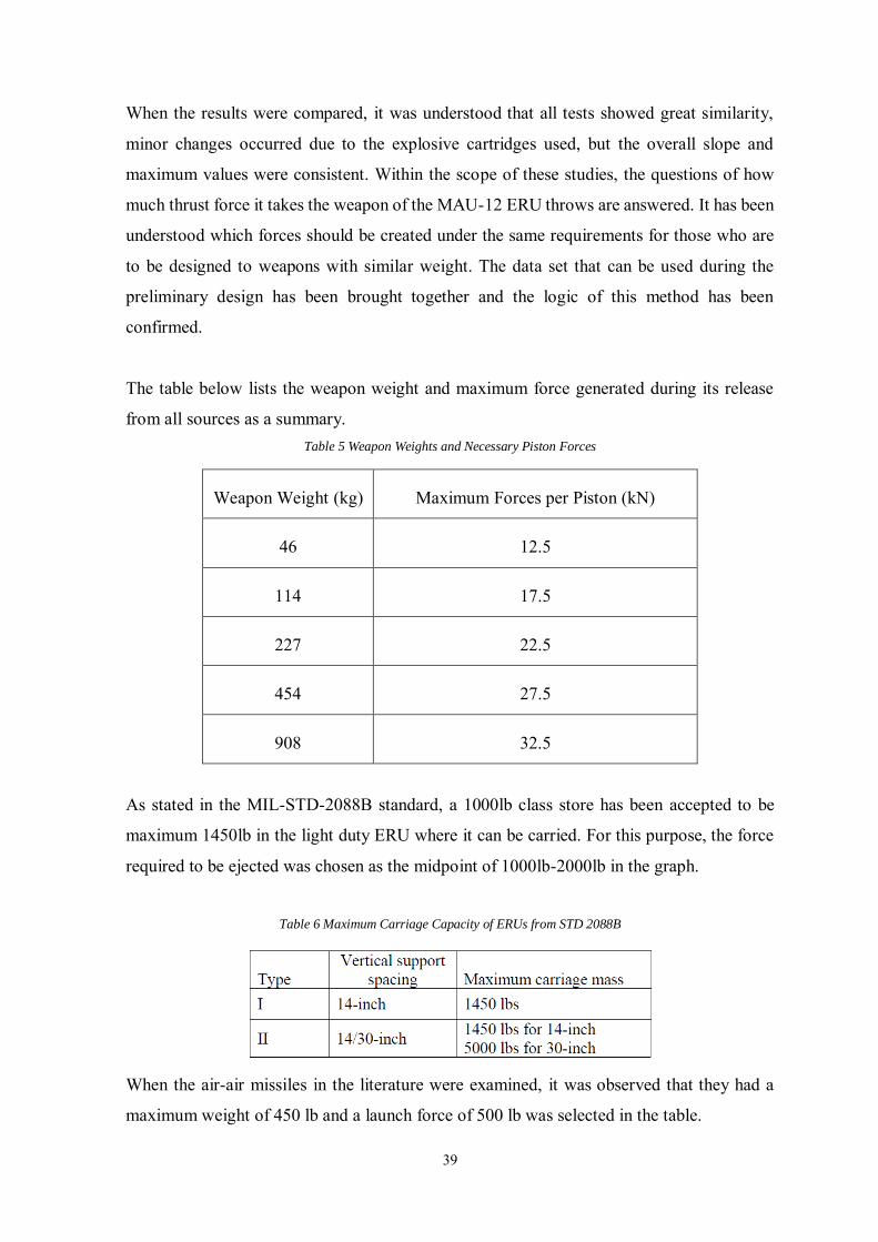
As shown in Figure 4-12, when the model was run, the impact forces were similar to Carter’s.
As a result of these studies, double check was performed on the performance data of the
MAU-12 field. The MAU-12 area, which has both 14 and 30 in suspension hooks, performs
proportional forces to weapon in various weights and performs separations in accordance
with the separation speed.
Figure 3-12 Ejector Simulink Model Results
Studies for MAU-12 have not only been limited to these but many data have been collected
due to their frequent use in our country. For this purpose, in order to enrich our defence
industry in terms of knowledge and gain the development capability that emits similar
features, static ejection measurements of the MK-82 bomb were carried out. These tests were
completed by performing many operations such as the change of thrust force over time, the
velocity values at the end of the stroke, the tension on the launcher and the weapon, force,
temperature values, and the processing of time measurements. In these tests carried out in
TUBITAK SAGE facilities in May 2014 within the scope of our country's facilities and
technology, force time graph has emerged. Because of classification just maximum forces
will be given as, in the range of 30-35kN force per piston for 500lb bomb ejection.
39
When the results were compared, it was understood that all tests showed great similarity,
minor changes occurred due to the explosive cartridges used, but the overall slope and
maximum values were consistent. Within the scope of these studies, the questions of how
much thrust force it takes the weapon of the MAU-12 ERU throws are answered. It has been
understood which forces should be created under the same requirements for those who are
to be designed to weapons with similar weight. The data set that can be used during the
preliminary design has been brought together and the logic of this method has been
confirmed.
The table below lists the weapon weight and maximum force generated during its release
from all sources as a summary. Table 5 Weapon Weights and Necessary Piston Forces
Weapon Weight (kg) Maximum Forces per Piston (kN)
46 12.5
114 17.5
227 22.5
454 27.5
908 32.5
As stated in the MIL-STD-2088B standard, a 1000lb class store has been accepted to be
maximum 1450lb in the light duty ERU where it can be carried. For this purpose, the force
required to be ejected was chosen as the midpoint of 1000lb-2000lb in the graph.
Table 6 Maximum Carriage Capacity of ERUs from STD 2088B
When the air-air missiles in the literature were examined, it was observed that they had a
maximum weight of 450 lb and a launch force of 500 lb was selected in the table.
40
3.3 Final Design Structural Optimization
In the defence industry, where cost and competition increase, the main purpose of companies
is to produce their products with as few materials as possible. A more detailed study was
needed during the attempts to produce the product that was suppressed with the high raw
material expenses that were attempted to be produced, with the least possible material. These
detailed studies have a serious impact on both the cost of production and the usability of the
product.
Structural optimization is trying to find the appropriate size, shape or material distribution
of a structure while satisfying different structural behaviour constraints to perform its task
in the best way [39]. Structural optimization techniques are generally developed to be used
towards the end of the design and there are many examples in the market that have become
widespread for this purpose. It is considered that more cost and time loss can be prevented
by using it in earlier stages to increase performance. Optimization can be summarized as the
fastest and most efficient solution to a problem in certain situations. It is generally divided
into three main sections. In the initial structural optimization studies, firstly size, then shape
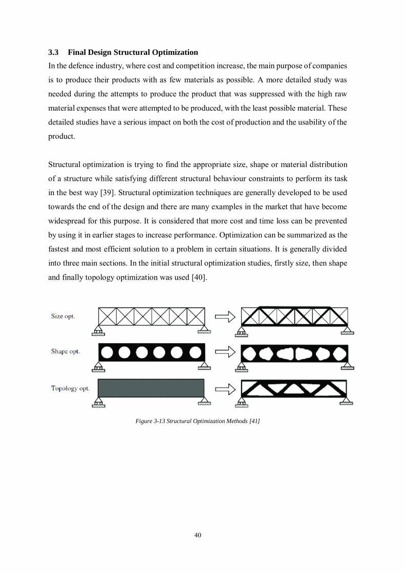
and finally topology optimization was used [40].
Figure 3-13 Structural Optimization Methods [41]
41
3.3.1 Size Optimization
Size Optimization is the simplest form among structural optimization techniques. The aim
is to dimensionally optimize the parts of the structure with known shape [42]. It is the aim
to reach the most efficient structure in size optimization without making any change in shape
and topology. Shape and material distribution are not affected.
Design variables width, height, length and thickness are handled iteratively within the scope
of this optimization technique. It is also preferred in studies to find the most efficient cross-
sectional area. As a result, it can be applied to 2D and 3D designs without effecting fasteners.
3.3.2 Shape Optimization
Shape optimization is called to try minimizing and optimizing the high stress that occurs in
the boundary of the structure [40].
With this technique, changes in the geometry of the structure are made without touching the
topology. Shape optimization does not change the total number of holes and the corner
curved surfaces in the design while handling with various iterations. It is emphasized that a
particular topology can be modified by studying with its geometry to suit the desired goal.
The difference of the topology optimization, which will be described later, will be clearer on
this issue. Just like size optimization, it can be used to find the optimum shape in 2 and 3
dimensional parts. The aim is to make holes and corner curves, which are more efficient, in
terms of vibration, durability, tension, or frequency by paying attention to the constraint
functions.
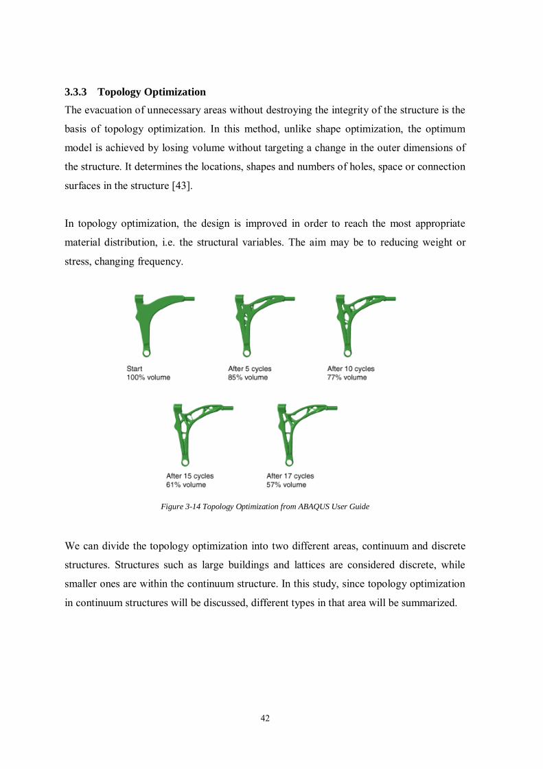
42
3.3.3 Topology Optimization
The evacuation of unnecessary areas without destroying the integrity of the structure is the
basis of topology optimization. In this method, unlike shape optimization, the optimum
model is achieved by losing volume without targeting a change in the outer dimensions of
the structure. It determines the locations, shapes and numbers of holes, space or connection
surfaces in the structure [43].
In topology optimization, the design is improved in order to reach the most appropriate
material distribution, i.e. the structural variables. The aim may be to reducing weight or
stress, changing frequency.
Figure 3-14 Topology Optimization from ABAQUS User Guide
We can divide the topology optimization into two different areas, continuum and discrete
structures. Structures such as large buildings and lattices are considered discrete, while
smaller ones are within the continuum structure. In this study, since topology optimization
in continuum structures will be discussed, different types in that area will be summarized.
43
3.3.3.1 Homogenization Method
In the homogenization method, it is aimed to reach the optimum target by changing the
dimensions of the spaces within the material of a certain design area. Distribution is
controlled by this method. Bendsøe and Kikuchin's work is an important milestone about the
use of this method in topology optimization. It is important that the method accept the
material property homogeneous for each element. The disadvantage is that the required
design variables are higher in number than other methods [44].
The aim of the homogenization method is to determine the possible association of
microstructure variables that minimize their functions. Global Stiffness, which is maximized
in order to minimize strain energy within a specified volume, can be expressed as follows
[45];
𝑆. 𝐸 =1
2𝑈𝑇𝐾𝑈
(3.31)
∑(1 − µ1µ2)ѵ𝑘 ≤ 𝑉∗
𝑘=𝑛
𝑘=1
(3.32)
S.E is the strain energy, U is the global displacement vector, K is the global stiffness matrix
and N is the number of finite elements.
3.3.3.2 Material Distribution Method (SIMP)
It is a method developed on the constant properties of the material in the elements. Physical
properties, element thickness or porosity are among the important parameters. By creating a
finite element model, it is aimed to reach the optimum element thickness. Meanwhile, Von
Misses stresses are taken into consideration. The model creation process continues after each
stress calculation. The regions that do not undergo stress are removed slowly and the most
robust structure is tried to be reached [46].
It can be seen as an advantage of this method to use the optimum design in terms of
manufacturability. In current applications, it can be said that this method was used in inplane
force situations, where it created an additional study requirement for three-dimensional load
cases after the study. This also appears as a disadvantage.
44
After a certain period, it was started to be called the punishment of solid isotropic materials
(SIMP). The density of each element, expressed as pseudo, takes a value between 0 and 1.
This value depends on the stiffness of the material. It can be expressed as follows.
𝑥𝑖 =𝜌𝑖
𝜌𝑜
(3.33)
𝜌𝑖 is the density of Ith element, 𝜌𝑜 is the density of the base material, 𝑥𝑖 is the pseudo-density
of the Ith element.
𝐾𝑖 = 𝑥𝑖𝑝𝐾𝑜
(3.34)
𝐾𝑜 is the stiffness of the base material, P is the penalization power and should be more than
1 . If 𝑥𝑖 and 𝐾𝑜 are 0 means no material exists, but the meaning of 1 is existing of material.
In solid isotropic materials punishment method , for optimal design middle densities cause
to inefficiency in case of selecting value P higher than 1.
3.3.3.3 Level Set Approach
It is a method based on boundary conditions between structural topology optimizations. The
basics are based on the work prepared by Osher and Sethian for monitoring free boundaries
with the average curvature [47]. Levet set movements from the current state of optimization
are changed along with boundary conditions.
The advantage of this method over SIMP is that the densities of middle value are not used.
Although it improves with the developing methods, it can be stated that it contains high
adherence to the structure in the initial design as a disadvantage [45].
𝑆(𝑡) = {𝑥(𝑡) ∶ Ф(𝑥(𝑡), 𝑡) = 𝑐}
(3.35)
C is the arbitrary constant, x is a point on boundary, level set vary with time. With this
equation and chain rule, application ensures the Hamilton-Jacobi equation.
45
𝜕Ф(𝑥, 𝑡)
𝜕𝑡+ 𝛻Ф(𝑥, 𝑡)
𝑑𝑥
𝑑𝑡= 0, Ф(𝑥, 0) = Ф0(𝑥)
(3.36)
𝑑𝑥
𝑑𝑡 is the movement of a point and expressed as position x. The optimum boundary can find
with the partial differential equation. X is a point in space on the izo-surface.
3.3.3.4 Evolutionary Structural Optimization
The method of adding or removing a certain number of elements in the design area is called
Evolutionary Structural Optimization. This material mobility is random. A criterion value is
calculated for each element named as sensivity number. Then, the lower value is deleted.
Numerical imbalances such as mesh dependencies can be shown as a disadvantage of this
method [45].
Within the scope of the evolutionary optimization method, the structure is first subjected to
topology optimization and then size optimization unlike other methods. If enough attention
is not paid to some design criteria within the scope of topology optimization, optimization
in the second stage may result in failure [48].
Maximizing stiffness under fixed volume constraint;
𝐶(𝑝) = 𝐹𝑇𝑈
(3.37)
𝑉∗ − ∑(𝑉𝑒𝑝𝑒) = 0
𝑁
𝑒=1
(3.38)
𝐾𝑈 = 𝐹 (3.39)
𝑝 = 𝑝𝑚𝑖𝑛 𝑜𝑟 1 (3.40)
46
3.3.3.5 Topology Optimization with ABAQUS and TOSCA
TOSCA is a program that cooperates with various finite element solvers (Abaqus, Ansys
and Nastran), optimizes size, shape and topology and offers economical, safe and efficient
solutions. Their solutions are flexible and non-parametric. In addition, there is a customized
'Tosca for Abaqus' plugin for Abaqus used in this study. Studies can be started directly under
the optimization title on 3D Abaqus models. This application is user-friendly as it can use
the post-process part of the Abaqus environment and control errors [49].
Figure 3-15 ABAQUS –TOSCA cycle
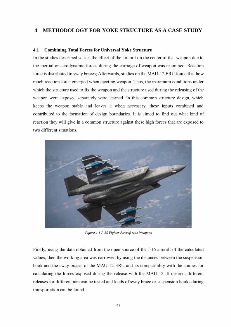
47
4 METHODOLOGY FOR YOKE STRUCTURE AS A CASE STUDY
4.1 Combining Total Forces for Universal Yoke Structure
In the studies described so far, the effect of the aircraft on the center of that weapon due to
the inertial or aerodynamic forces during the carriage of weapon was examined. Reaction
force is distributed to sway braces; Afterwards, studies on the MAU-12 ERU found that how
much reaction force emerged when ejecting weapon. Thus, the maximum conditions under
which the structure used to fix the weapon and the structure used during the releasing of the
weapon were exposed separately were learned. In this common structure design, which
keeps the weapon stable and leaves it when necessary, these inputs combined and
contributed to the formation of design boundaries. It is aimed to find out what kind of
reaction they will give in a common structure against these high forces that are exposed to
two different situations.
Figure 4-1 F-35 Fighter Aircraft with Weapons
Firstly, using the data obtained from the open source of the f-16 aircraft of the calculated
values, then the working area was narrowed by using the distances between the suspension
hook and the sway braces of the MAU-12 ERU and its compatibility with the studies for
calculating the forces exposed during the release with the MAU-12. If desired, different
releases for different airs can be tested and loads of sway brace or suspension hooks during
transportation can be found.
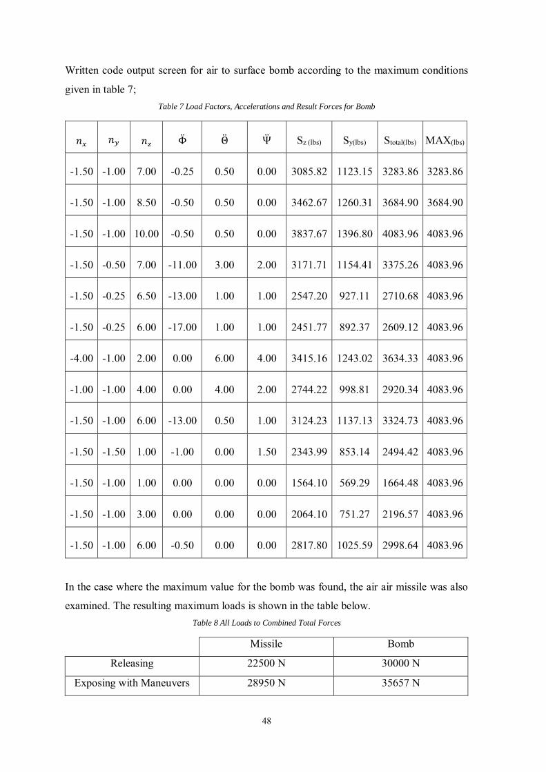
48
Written code output screen for air to surface bomb according to the maximum conditions
given in table 7; Table 7 Load Factors, Accelerations and Result Forces for Bomb
𝑛𝑥 𝑛𝑦 𝑛𝑧 Φ̈ Θ̈ Ψ̈ Sz (lbs) Sy(lbs) Stotal(lbs) MAX(lbs)
-1.50 -1.00 7.00 -0.25 0.50 0.00 3085.82 1123.15 3283.86 3283.86
-1.50 -1.00 8.50 -0.50 0.50 0.00 3462.67 1260.31 3684.90 3684.90
-1.50 -1.00 10.00 -0.50 0.50 0.00 3837.67 1396.80 4083.96 4083.96
-1.50 -0.50 7.00 -11.00 3.00 2.00 3171.71 1154.41 3375.26 4083.96
-1.50 -0.25 6.50 -13.00 1.00 1.00 2547.20 927.11 2710.68 4083.96
-1.50 -0.25 6.00 -17.00 1.00 1.00 2451.77 892.37 2609.12 4083.96
-4.00 -1.00 2.00 0.00 6.00 4.00 3415.16 1243.02 3634.33 4083.96
-1.00 -1.00 4.00 0.00 4.00 2.00 2744.22 998.81 2920.34 4083.96
-1.50 -1.00 6.00 -13.00 0.50 1.00 3124.23 1137.13 3324.73 4083.96
-1.50 -1.50 1.00 -1.00 0.00 1.50 2343.99 853.14 2494.42 4083.96
-1.50 -1.00 1.00 0.00 0.00 0.00 1564.10 569.29 1664.48 4083.96
-1.50 -1.00 3.00 0.00 0.00 0.00 2064.10 751.27 2196.57 4083.96
-1.50 -1.00 6.00 -0.50 0.00 0.00 2817.80 1025.59 2998.64 4083.96
In the case where the maximum value for the bomb was found, the air air missile was also
examined. The resulting maximum loads is shown in the table below. Table 8 All Loads to Combined Total Forces
Missile Bomb
Releasing 22500 N 30000 N
Exposing with Maneuvers 28950 N 35657 N
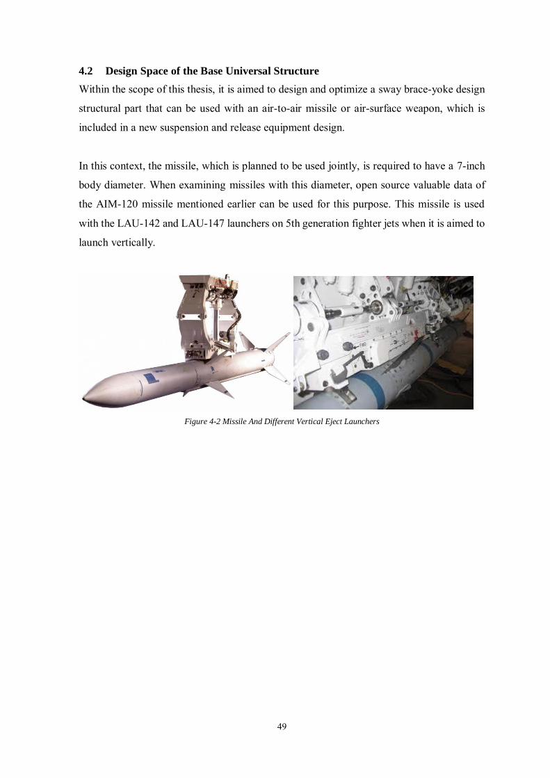
49
4.2 Design Space of the Base Universal Structure
Within the scope of this thesis, it is aimed to design and optimize a sway brace-yoke design
structural part that can be used with an air-to-air missile or air-surface weapon, which is
included in a new suspension and release equipment design.
In this context, the missile, which is planned to be used jointly, is required to have a 7-inch
body diameter. When examining missiles with this diameter, open source valuable data of
the AIM-120 missile mentioned earlier can be used for this purpose. This missile is used
with the LAU-142 and LAU-147 launchers on 5th generation fighter jets when it is aimed to
launch vertically.
Figure 4-2 Missile And Different Vertical Eject Launchers
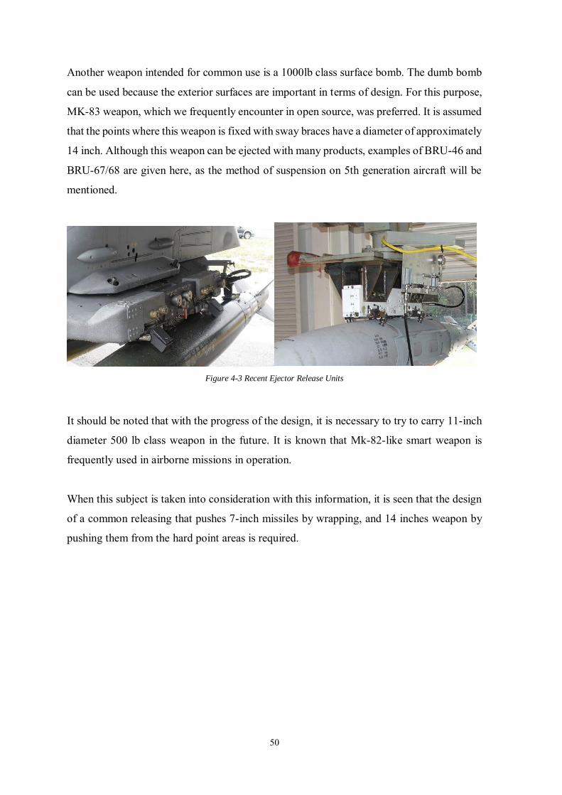
50
Another weapon intended for common use is a 1000lb class surface bomb. The dumb bomb
can be used because the exterior surfaces are important in terms of design. For this purpose,
MK-83 weapon, which we frequently encounter in open source, was preferred. It is assumed
that the points where this weapon is fixed with sway braces have a diameter of approximately
14 inch. Although this weapon can be ejected with many products, examples of BRU-46 and
BRU-67/68 are given here, as the method of suspension on 5th generation aircraft will be
mentioned.
Figure 4-3 Recent Ejector Release Units
It should be noted that with the progress of the design, it is necessary to try to carry 11-inch
diameter 500 lb class weapon in the future. It is known that Mk-82-like smart weapon is
frequently used in airborne missions in operation.
When this subject is taken into consideration with this information, it is seen that the design
of a common releasing that pushes 7-inch missiles by wrapping, and 14 inches weapon by
pushing them from the hard point areas is required.
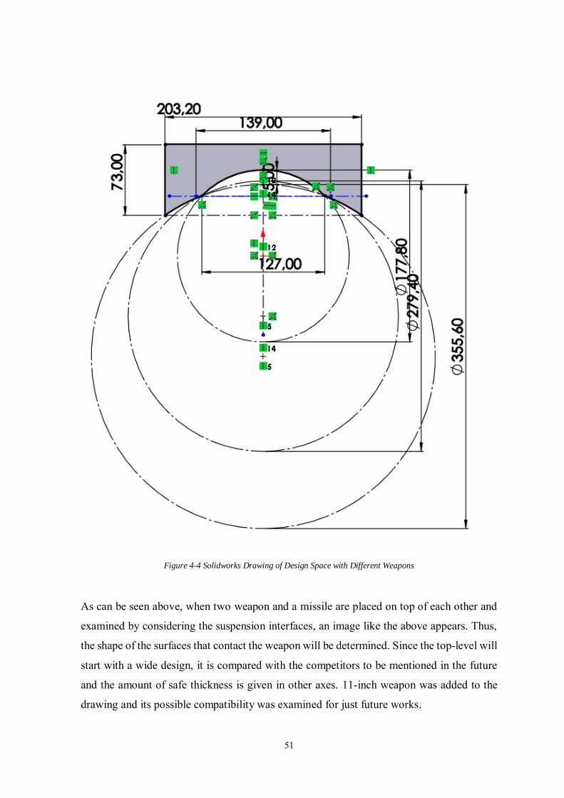
51
Figure 4-4 Solidworks Drawing of Design Space with Different Weapons
As can be seen above, when two weapon and a missile are placed on top of each other and
examined by considering the suspension interfaces, an image like the above appears. Thus,
the shape of the surfaces that contact the weapon will be determined. Since the top-level will
start with a wide design, it is compared with the competitors to be mentioned in the future
and the amount of safe thickness is given in other axes. 11-inch weapon was added to the
drawing and its possible compatibility was examined for just future works.
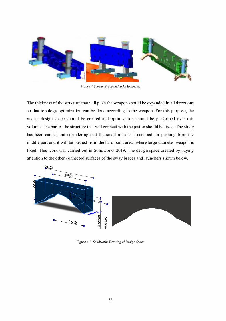
52
Figure 4-5 Sway Brace and Yoke Examples
The thickness of the structure that will push the weapon should be expanded in all directions
so that topology optimization can be done according to the weapon. For this purpose, the
widest design space should be created and optimization should be performed over this
volume. The part of the structure that will connect with the piston should be fixed. The study
has been carried out considering that the small missile is certified for pushing from the
middle part and it will be pushed from the hard point areas where large diameter weapon is
fixed. This work was carried out in Solidworks 2019. The design space created by paying
attention to the other connected surfaces of the sway braces and launchers shown below.
Figure 4-6 Solidworks Drawing of Design Space
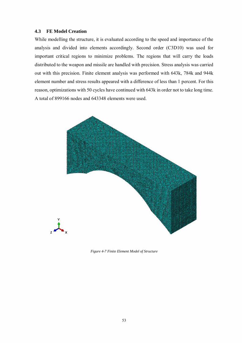
53
4.3 FE Model Creation
While modelling the structure, it is evaluated according to the speed and importance of the
analysis and divided into elements accordingly. Second order (C3D10) was used for
important critical regions to minimize problems. The regions that will carry the loads
distributed to the weapon and missile are handled with precision. Stress analysis was carried
out with this precision. Finite element analysis was performed with 643k, 784k and 944k
element number and stress results appeared with a difference of less than 1 percent. For this
reason, optimizations with 50 cycles have continued with 643k in order not to take long time.
A total of 899166 nodes and 643348 elements were used.
Figure 4-7 Finite Element Model of Structure
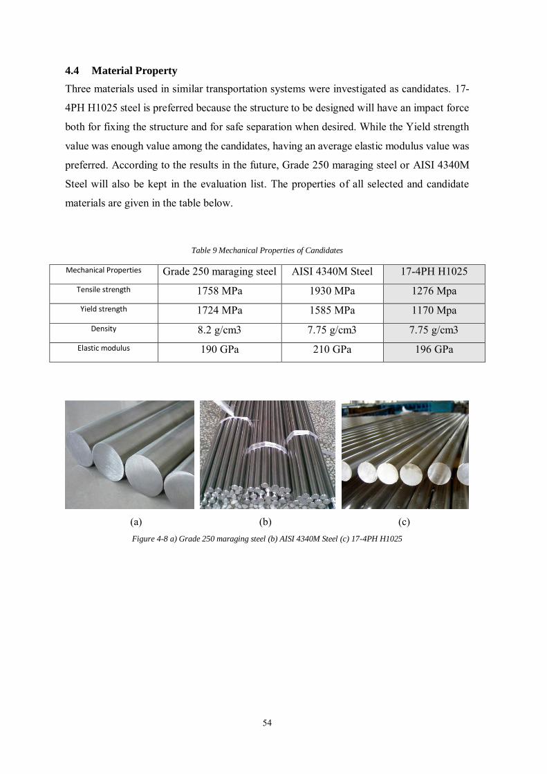
54
4.4 Material Property
Three materials used in similar transportation systems were investigated as candidates. 17-
4PH H1025 steel is preferred because the structure to be designed will have an impact force
both for fixing the structure and for safe separation when desired. While the Yield strength
value was enough value among the candidates, having an average elastic modulus value was
preferred. According to the results in the future, Grade 250 maraging steel or AISI 4340M
Steel will also be kept in the evaluation list. The properties of all selected and candidate
materials are given in the table below.
Table 9 Mechanical Properties of Candidates
Mechanical Properties Grade 250 maraging steel AISI 4340M Steel 17-4PH H1025 Tensile strength 1758 MPa 1930 MPa 1276 Mpa Yield strength 1724 MPa 1585 MPa 1170 Mpa
Density 8.2 g/cm3 7.75 g/cm3 7.75 g/cm3 Elastic modulus 190 GPa 210 GPa 196 GPa
(a) (b) (c) Figure 4-8 a) Grade 250 maraging steel (b) AISI 4340M Steel (c) 17-4PH H1025
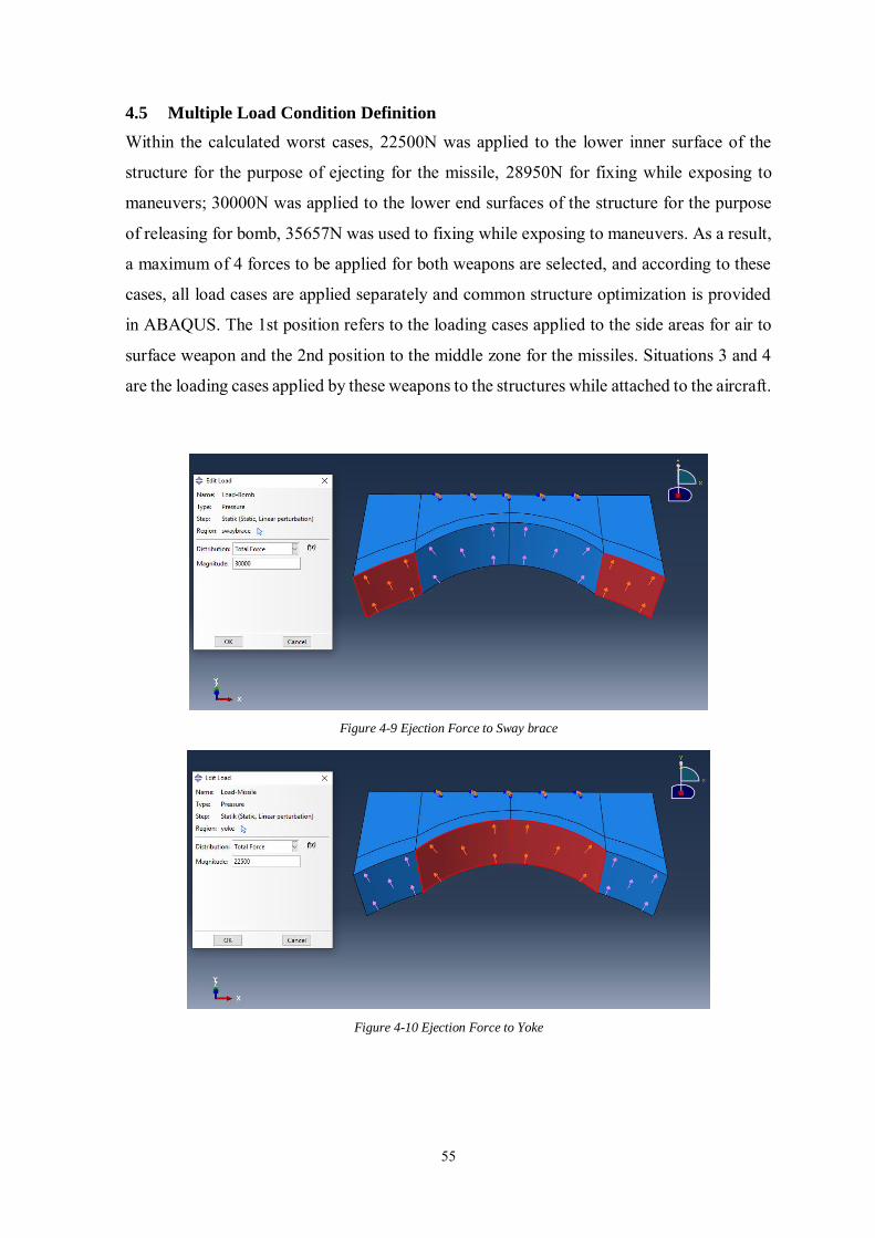
55
4.5 Multiple Load Condition Definition
Within the calculated worst cases, 22500N was applied to the lower inner surface of the
structure for the purpose of ejecting for the missile, 28950N for fixing while exposing to
maneuvers; 30000N was applied to the lower end surfaces of the structure for the purpose
of releasing for bomb, 35657N was used to fixing while exposing to maneuvers. As a result,
a maximum of 4 forces to be applied for both weapons are selected, and according to these
cases, all load cases are applied separately and common structure optimization is provided
in ABAQUS. The 1st position refers to the loading cases applied to the side areas for air to
surface weapon and the 2nd position to the middle zone for the missiles. Situations 3 and 4
are the loading cases applied by these weapons to the structures while attached to the aircraft.
Figure 4-9 Ejection Force to Sway brace
Figure 4-10 Ejection Force to Yoke
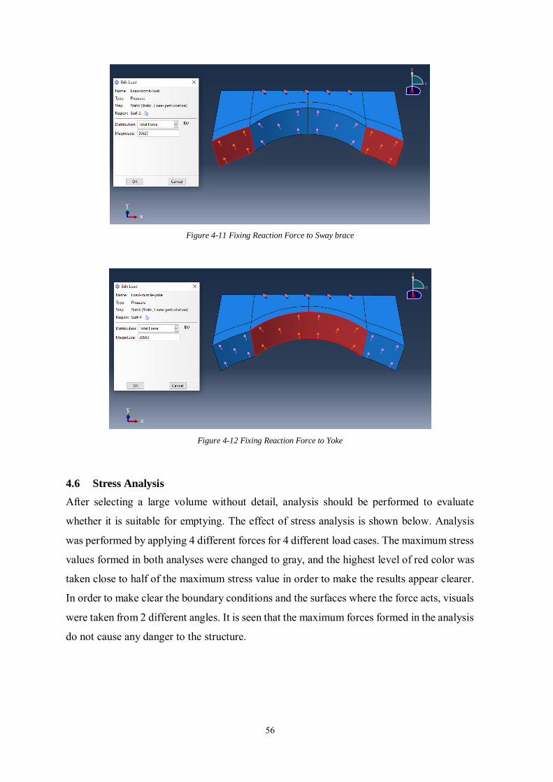
56
Figure 4-11 Fixing Reaction Force to Sway brace
Figure 4-12 Fixing Reaction Force to Yoke
4.6 Stress Analysis
After selecting a large volume without detail, analysis should be performed to evaluate
whether it is suitable for emptying. The effect of stress analysis is shown below. Analysis
was performed by applying 4 different forces for 4 different load cases. The maximum stress
values formed in both analyses were changed to gray, and the highest level of red color was
taken close to half of the maximum stress value in order to make the results appear clearer.
In order to make clear the boundary conditions and the surfaces where the force acts, visuals
were taken from 2 different angles. It is seen that the maximum forces formed in the analysis
do not cause any danger to the structure.
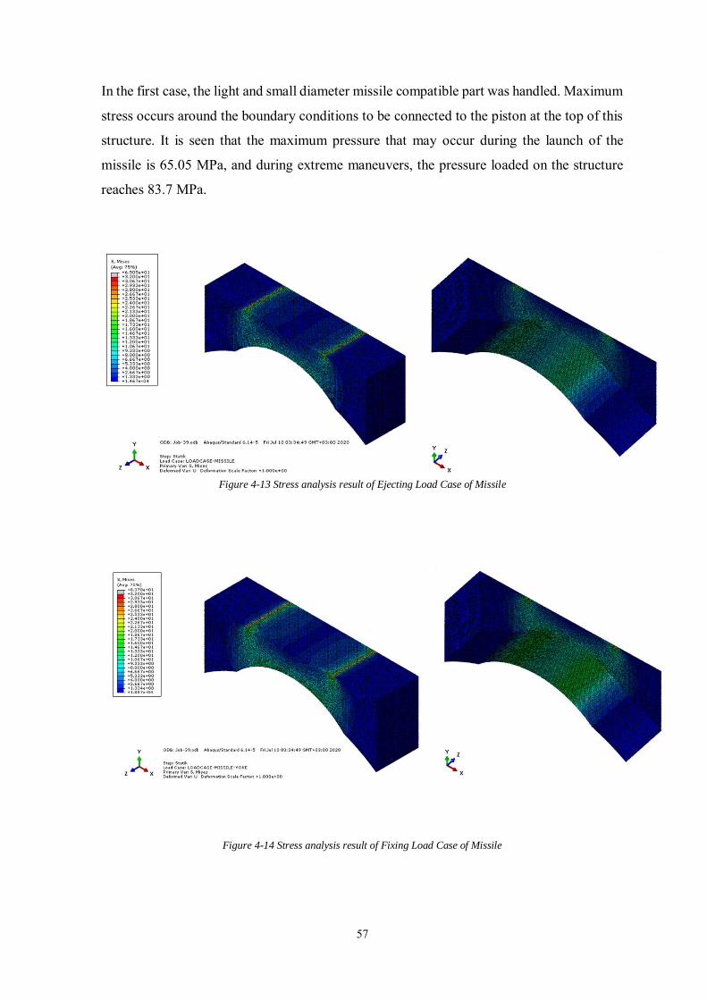
57
In the first case, the light and small diameter missile compatible part was handled. Maximum
stress occurs around the boundary conditions to be connected to the piston at the top of this
structure. It is seen that the maximum pressure that may occur during the launch of the
missile is 65.05 MPa, and during extreme maneuvers, the pressure loaded on the structure
reaches 83.7 MPa.
Figure 4-13 Stress analysis result of Ejecting Load Case of Missile
Figure 4-14 Stress analysis result of Fixing Load Case of Missile
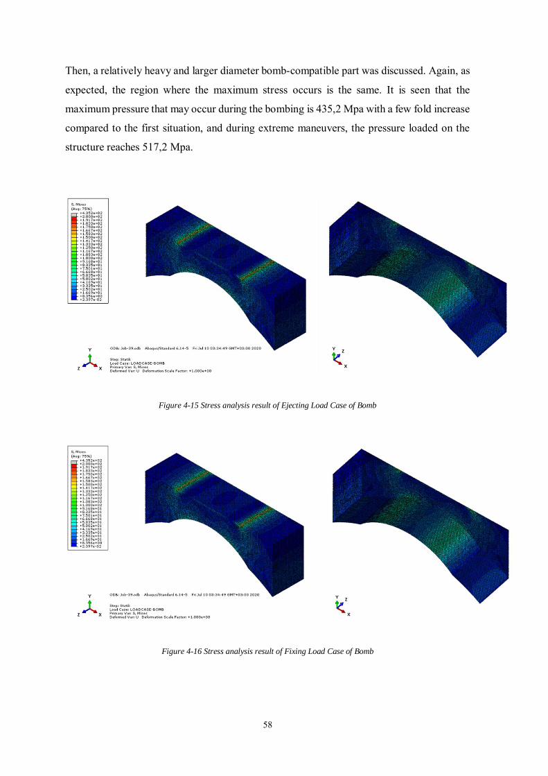
58
Then, a relatively heavy and larger diameter bomb-compatible part was discussed. Again, as
expected, the region where the maximum stress occurs is the same. It is seen that the
maximum pressure that may occur during the bombing is 435,2 Mpa with a few fold increase
compared to the first situation, and during extreme maneuvers, the pressure loaded on the
structure reaches 517,2 Mpa.
Figure 4-15 Stress analysis result of Ejecting Load Case of Bomb
Figure 4-16 Stress analysis result of Fixing Load Case of Bomb
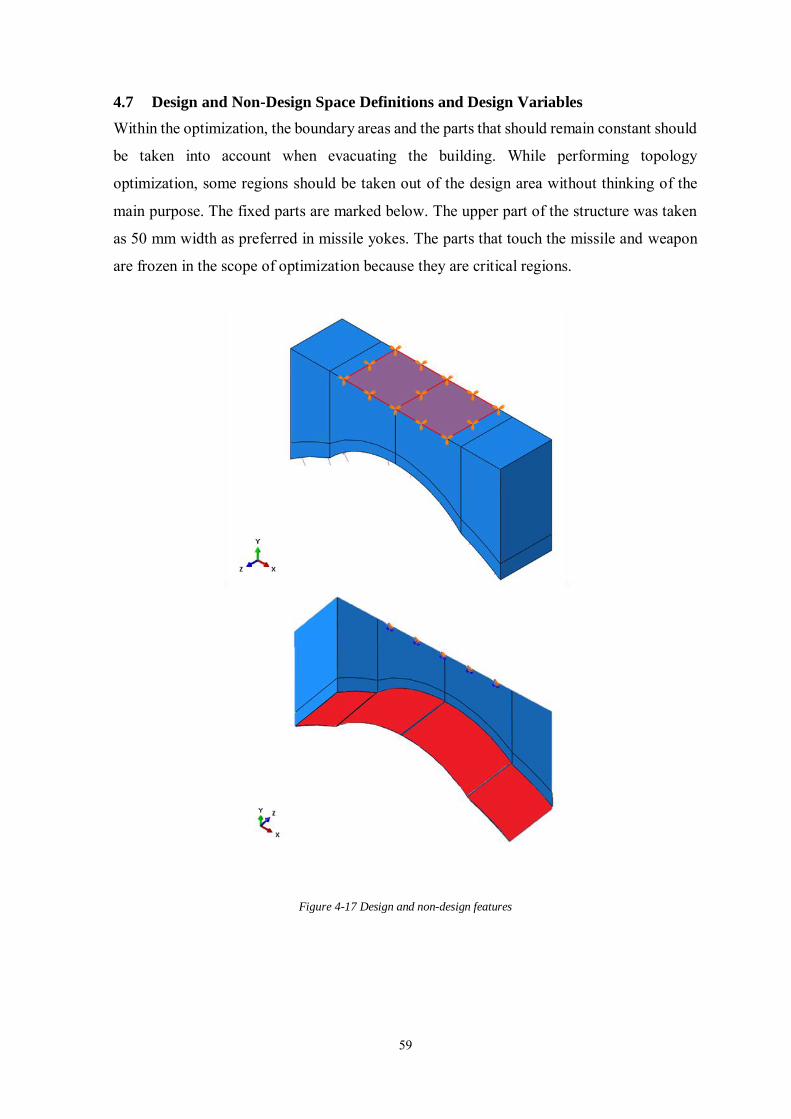
59
4.7 Design and Non-Design Space Definitions and Design Variables
Within the optimization, the boundary areas and the parts that should remain constant should
be taken into account when evacuating the building. While performing topology
optimization, some regions should be taken out of the design area without thinking of the
main purpose. The fixed parts are marked below. The upper part of the structure was taken
as 50 mm width as preferred in missile yokes. The parts that touch the missile and weapon
are frozen in the scope of optimization because they are critical regions.
Figure 4-17 Design and non-design features
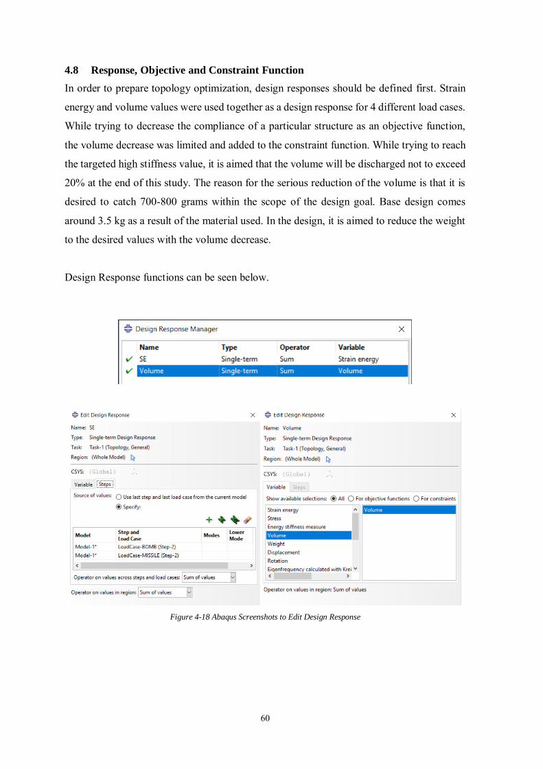
60
4.8 Response, Objective and Constraint Function
In order to prepare topology optimization, design responses should be defined first. Strain
energy and volume values were used together as a design response for 4 different load cases.
While trying to decrease the compliance of a particular structure as an objective function,
the volume decrease was limited and added to the constraint function. While trying to reach
the targeted high stiffness value, it is aimed that the volume will be discharged not to exceed
20% at the end of this study. The reason for the serious reduction of the volume is that it is
desired to catch 700-800 grams within the scope of the design goal. Base design comes
around 3.5 kg as a result of the material used. In the design, it is aimed to reduce the weight
to the desired values with the volume decrease.
Design Response functions can be seen below.
Figure 4-18 Abaqus Screenshots to Edit Design Response
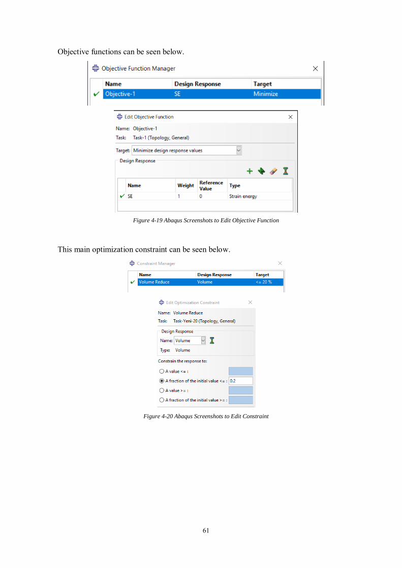
61
Objective functions can be seen below.
Figure 4-19 Abaqus Screenshots to Edit Objective Function
This main optimization constraint can be seen below.
Figure 4-20 Abaqus Screenshots to Edit Constraint
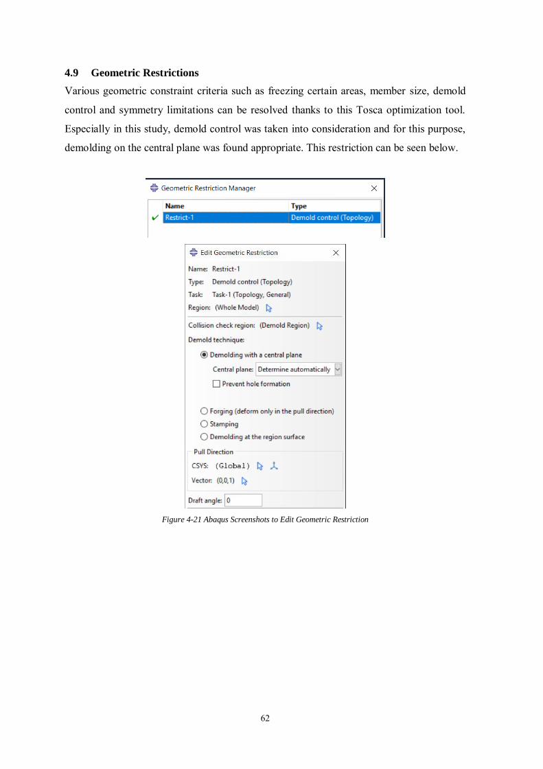
62
4.9 Geometric Restrictions
Various geometric constraint criteria such as freezing certain areas, member size, demold
control and symmetry limitations can be resolved thanks to this Tosca optimization tool.
Especially in this study, demold control was taken into consideration and for this purpose,
demolding on the central plane was found appropriate. This restriction can be seen below.
Figure 4-21 Abaqus Screenshots to Edit Geometric Restriction
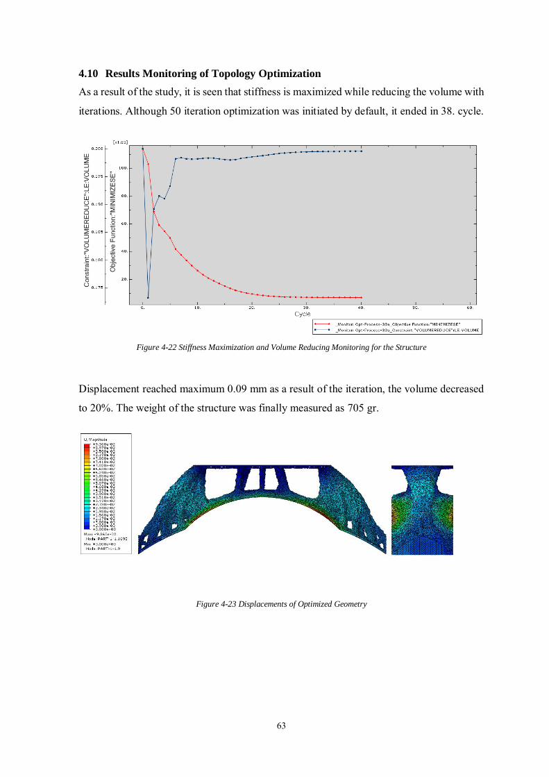
63
4.10 Results Monitoring of Topology Optimization
As a result of the study, it is seen that stiffness is maximized while reducing the volume with
iterations. Although 50 iteration optimization was initiated by default, it ended in 38. cycle.
Figure 4-22 Stiffness Maximization and Volume Reducing Monitoring for the Structure
Displacement reached maximum 0.09 mm as a result of the iteration, the volume decreased
to 20%. The weight of the structure was finally measured as 705 gr.
Figure 4-23 Displacements of Optimized Geometry
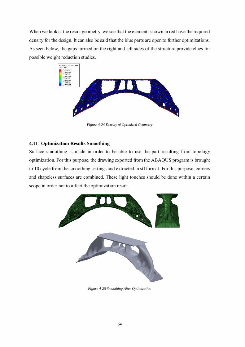
64
When we look at the result geometry, we see that the elements shown in red have the required
density for the design. It can also be said that the blue parts are open to further optimizations.
As seen below, the gaps formed on the right and left sides of the structure provide clues for
possible weight reduction studies.
Figure 4-24 Density of Optimized Geometry
4.11 Optimization Results Smoothing
Surface smoothing is made in order to be able to use the part resulting from topology
optimization. For this purpose, the drawing exported from the ABAQUS program is brought
to 10 cycle from the smoothing settings and extracted in stl format. For this purpose, corners
and shapeless surfaces are combined. These light touches should be done within a certain
scope in order not to affect the optimization result.
Figure 4-25 Smoothing After Optimization
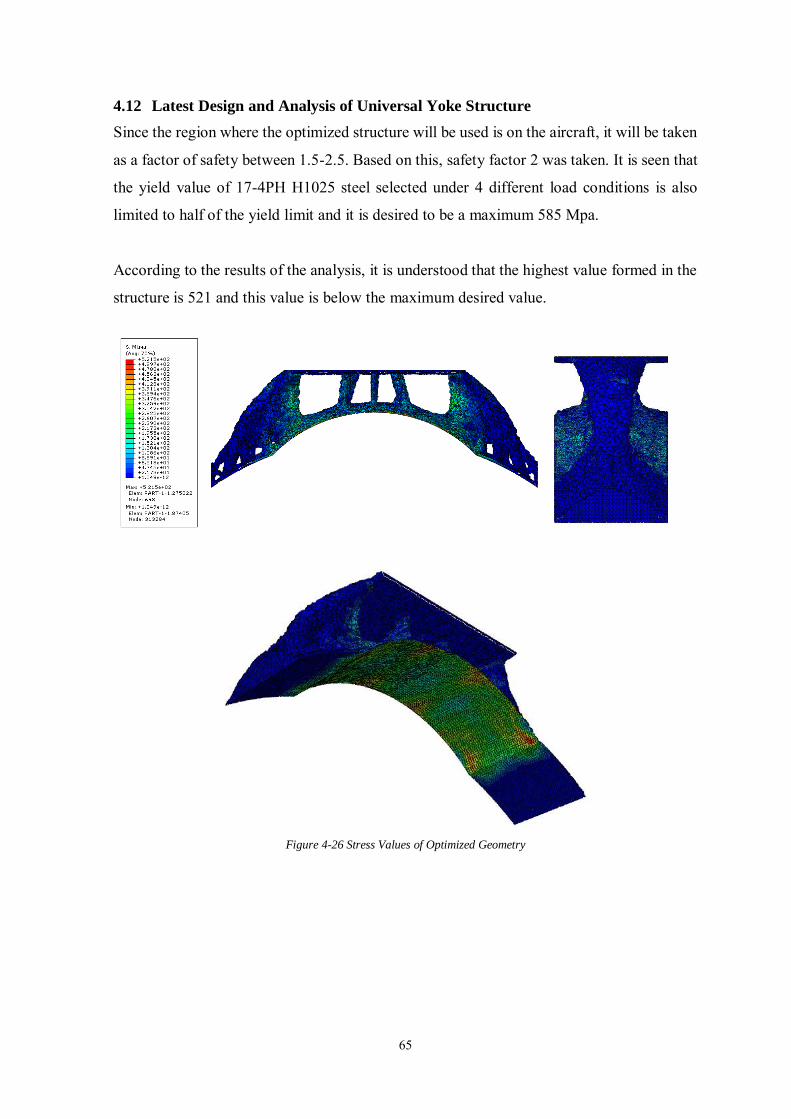
65
4.12 Latest Design and Analysis of Universal Yoke Structure
Since the region where the optimized structure will be used is on the aircraft, it will be taken
as a factor of safety between 1.5-2.5. Based on this, safety factor 2 was taken. It is seen that
the yield value of 17-4PH H1025 steel selected under 4 different load conditions is also
limited to half of the yield limit and it is desired to be a maximum 585 Mpa.
According to the results of the analysis, it is understood that the highest value formed in the
structure is 521 and this value is below the maximum desired value.
Figure 4-26 Stress Values of Optimized Geometry
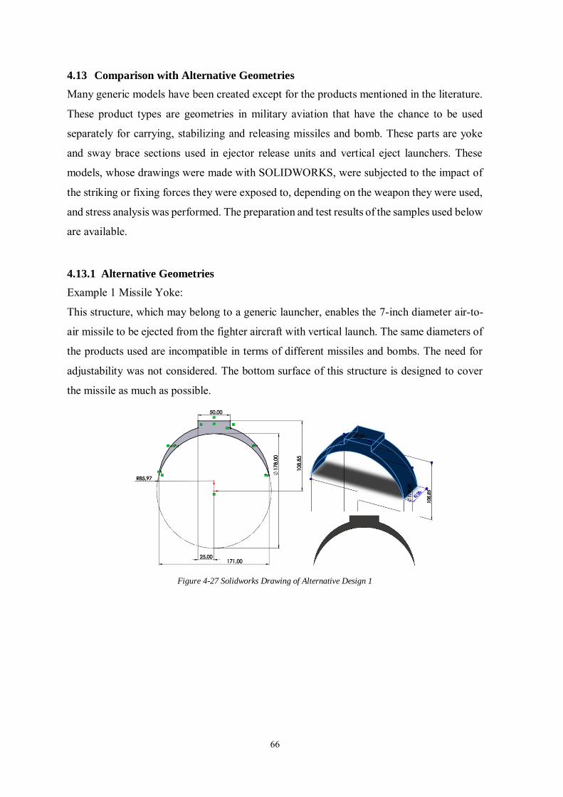
66
4.13 Comparison with Alternative Geometries
Many generic models have been created except for the products mentioned in the literature.
These product types are geometries in military aviation that have the chance to be used
separately for carrying, stabilizing and releasing missiles and bomb. These parts are yoke
and sway brace sections used in ejector release units and vertical eject launchers. These
models, whose drawings were made with SOLIDWORKS, were subjected to the impact of
the striking or fixing forces they were exposed to, depending on the weapon they were used,
and stress analysis was performed. The preparation and test results of the samples used below
are available.
4.13.1 Alternative Geometries
Example 1 Missile Yoke:
This structure, which may belong to a generic launcher, enables the 7-inch diameter air-to-
air missile to be ejected from the fighter aircraft with vertical launch. The same diameters of
the products used are incompatible in terms of different missiles and bombs. The need for
adjustability was not considered. The bottom surface of this structure is designed to cover
the missile as much as possible.
Figure 4-27 Solidworks Drawing of Alternative Design 1
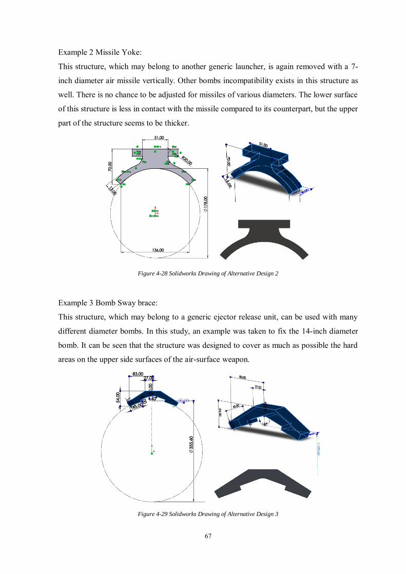
67
Example 2 Missile Yoke:
This structure, which may belong to another generic launcher, is again removed with a 7-
inch diameter air missile vertically. Other bombs incompatibility exists in this structure as
well. There is no chance to be adjusted for missiles of various diameters. The lower surface
of this structure is less in contact with the missile compared to its counterpart, but the upper
part of the structure seems to be thicker.
Figure 4-28 Solidworks Drawing of Alternative Design 2
Example 3 Bomb Sway brace:
This structure, which may belong to a generic ejector release unit, can be used with many
different diameter bombs. In this study, an example was taken to fix the 14-inch diameter
bomb. It can be seen that the structure was designed to cover as much as possible the hard
areas on the upper side surfaces of the air-surface weapon.
Figure 4-29 Solidworks Drawing of Alternative Design 3
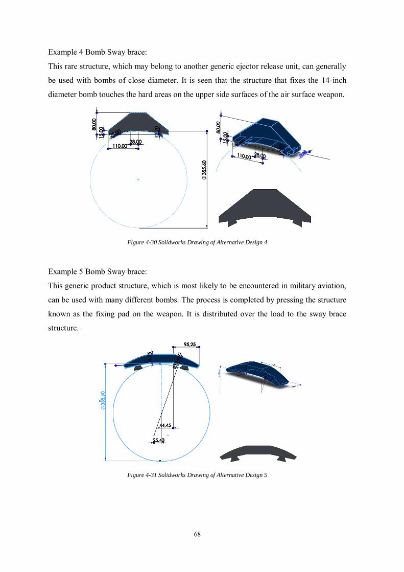
68
Example 4 Bomb Sway brace:
This rare structure, which may belong to another generic ejector release unit, can generally
be used with bombs of close diameter. It is seen that the structure that fixes the 14-inch
diameter bomb touches the hard areas on the upper side surfaces of the air surface weapon.
Figure 4-30 Solidworks Drawing of Alternative Design 4
Example 5 Bomb Sway brace:
This generic product structure, which is most likely to be encountered in military aviation,
can be used with many different bombs. The process is completed by pressing the structure
known as the fixing pad on the weapon. It is distributed over the load to the sway brace
structure.
Figure 4-31 Solidworks Drawing of Alternative Design 5
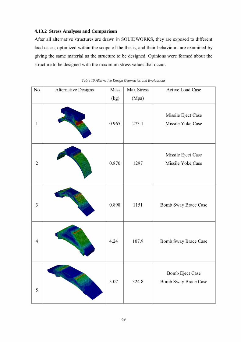
69
4.13.2 Stress Analyses and Comparison
After all alternative structures are drawn in SOLIDWORKS, they are exposed to different
load cases, optimized within the scope of the thesis, and their behaviours are examined by
giving the same material as the structure to be designed. Opinions were formed about the
structure to be designed with the maximum stress values that occur.
Table 10 Alternative Design Geometries and Evaluations
No Alternative Designs Mass
(kg)
Max Stress
(Mpa)
Active Load Case
1
0.965
273.1
Missile Eject Case
Missile Yoke Case
2
0.870
1297
Missile Eject Case
Missile Yoke Case
3
0.898
1151
Bomb Sway Brace Case
4
4.24
107.9
Bomb Sway Brace Case
5
3.07
324.8
Bomb Eject Case
Bomb Sway Brace Case
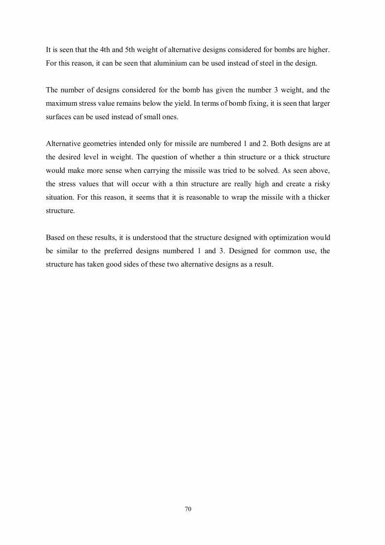
70
It is seen that the 4th and 5th weight of alternative designs considered for bombs are higher.
For this reason, it can be seen that aluminium can be used instead of steel in the design.
The number of designs considered for the bomb has given the number 3 weight, and the
maximum stress value remains below the yield. In terms of bomb fixing, it is seen that larger
surfaces can be used instead of small ones.
Alternative geometries intended only for missile are numbered 1 and 2. Both designs are at
the desired level in weight. The question of whether a thin structure or a thick structure
would make more sense when carrying the missile was tried to be solved. As seen above,
the stress values that will occur with a thin structure are really high and create a risky
situation. For this reason, it seems that it is reasonable to wrap the missile with a thicker
structure.
Based on these results, it is understood that the structure designed with optimization would
be similar to the preferred designs numbered 1 and 3. Designed for common use, the
structure has taken good sides of these two alternative designs as a result.
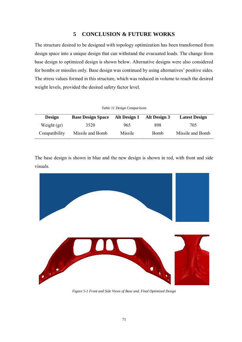
71
5 CONCLUSION & FUTURE WORKS
The structure desired to be designed with topology optimization has been transformed from
design space into a unique design that can withstand the evacuated loads. The change from
base design to optimized design is shown below. Alternative designs were also considered
for bombs or missiles only. Base design was continued by using alternatives’ positive sides.
The stress values formed in this structure, which was reduced in volume to reach the desired
weight levels, provided the desired safety factor level.
Table 11 Design Comparisons
Design Base Design Space Alt Design 1 Alt Design 3 Latest Design
Weight (gr) 3520 965 898 705
Compatibility Missile and Bomb Missile Bomb Missile and Bomb
The base design is shown in blue and the new design is shown in red, with front and side
visuals.
Figure 5-1 Front and Side Views of Base and. Final Optimized Design
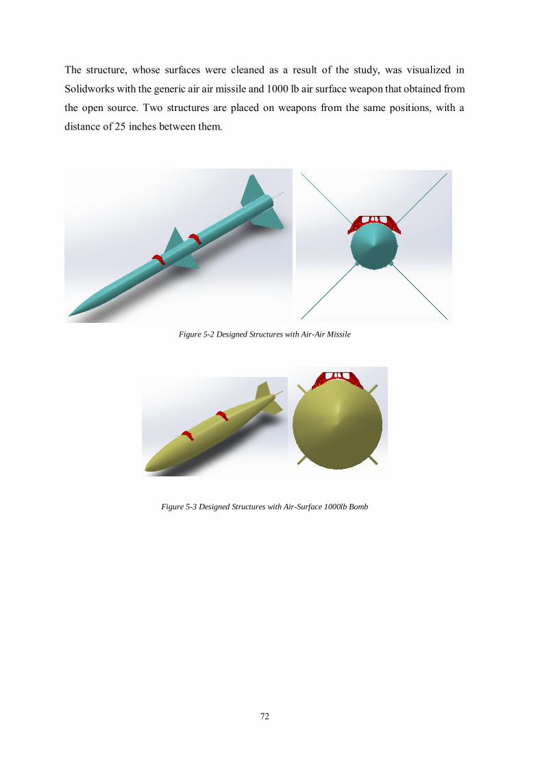
72
The structure, whose surfaces were cleaned as a result of the study, was visualized in
Solidworks with the generic air air missile and 1000 lb air surface weapon that obtained from
the open source. Two structures are placed on weapons from the same positions, with a
distance of 25 inches between them.
Figure 5-2 Designed Structures with Air-Air Missile
Figure 5-3 Designed Structures with Air-Surface 1000lb Bomb
73
The main goal of this shudy is to create a basic guideway for aircraft application that can be
assist to anyone who wants to develop a part on the fighter aircraft. Calculation of the forces
and moments on this related product, aim to gain literature for our country. This goal was
accomplished on important interfaces for mentioned hard maneuvers. When it comes to
designing a part on the fighter aircraft, it is critical to determine extreme conditions. Weapon
systems have chosen as an example these parts. The relevant part of suspension and release
system designed with optimization to reduce the weight. While designing this product, it is
aimed to be universal for both air-air missiles and air-surface bombs. As a result of this study
shows us a couple of maneuvers which push to aircraft its limits can be used calculation of
maximum forces which occurs at interface areas between store and aircraft. It is understood
that inertial loads are more determinant than aerodynamic loads at carriage phase. It has been
observed that the forces resulting from fixing the weapon are as important as the forces
required to eject it. It was emphasized that this study was carried out to guide the preliminary
design process, maximum forces would be sufficient and the design process should be
matured with feedback from flight and ground tests.
In this study, inertial and basic aerodynamic factors have been used to calculate the loads to
be caused by maneuver, but in future studies aerodynamic calculations can be detailed on
carrying on the wing. These studies may include the flutter effect. With the data taken with
flight tests, error reduction can be made on the results of the study. Different combinations
of suspension and release equipment and weapon can be studied. Considering that there are
7 and 14 inch diameter weapons within the scope of the study, compatibility studies can be
performed for 500lb weapon with a diameter of 11 inch as mentioned before. Ejecting tests
are required even if this study has been carried out by paying attention to the hard point of
the weapon. Ejecting bomb with two structures in 25 inch spacing can be observed in test
setups. Additive manufacturing or composite content is seen as an opportunity in material
selection and production. Material selection can be further elaborated to work on different
combinations. Each work mentioned within the scope of future work will help guide the
methods that can be used in the preliminary design of future projects and provide more
accurate results.
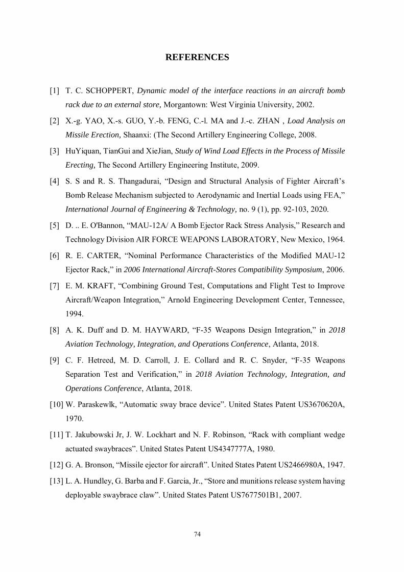
74
REFERENCES
[1] T. C. SCHOPPERT, Dynamic model of the interface reactions in an aircraft bomb
rack due to an external store, Morgantown: West Virginia University, 2002.
[2] X.-g. YAO, X.-s. GUO, Y.-b. FENG, C.-l. MA and J.-c. ZHAN , Load Analysis on
Missile Erection, Shaanxi: (The Second Artillery Engineering College, 2008.
[3] HuYiquan, TianGui and XieJian, Study of Wind Load Effects in the Process of Missile
Erecting, The Second Artillery Engineering Institute, 2009.
[4] S. S and R. S. Thangadurai, “Design and Structural Analysis of Fighter Aircraft’s
Bomb Release Mechanism subjected to Aerodynamic and Inertial Loads using FEA,”
International Journal of Engineering & Technology, no. 9 (1), pp. 92-103, 2020.
[5] D. .. E. O'Bannon, “MAU-12A/ A Bomb Ejector Rack Stress Analysis,” Research and
Technology Division AIR FORCE WEAPONS LABORATORY, New Mexico, 1964.
[6] R. E. CARTER, “Nominal Performance Characteristics of the Modified MAU-12
Ejector Rack,” in 2006 International Aircraft-Stores Compatibility Symposium, 2006.
[7] E. M. KRAFT, “Combining Ground Test, Computations and Flight Test to Improve
Aircraft/Weapon Integration,” Arnold Engineering Development Center, Tennessee,
1994.
[8] A. K. Duff and D. M. HAYWARD, “F-35 Weapons Design Integration,” in 2018
Aviation Technology, Integration, and Operations Conference, Atlanta, 2018.
[9] C. F. Hetreed, M. D. Carroll, J. E. Collard and R. C. Snyder, “F-35 Weapons
Separation Test and Verification,” in 2018 Aviation Technology, Integration, and
Operations Conference, Atlanta, 2018.
[10] W. Paraskewlk, “Automatic sway brace device”. United States Patent US3670620A,
1970.
[11] T. Jakubowski Jr, J. W. Lockhart and N. F. Robinson, “Rack with compliant wedge
actuated swaybraces”. United States Patent US4347777A, 1980.
[12] G. A. Bronson, “Missile ejector for aircraft”. United States Patent US2466980A, 1947.
[13] L. A. Hundley, G. Barba and F. Garcia, Jr., “Store and munitions release system having
deployable swaybrace claw”. United States Patent US7677501B1, 2007.
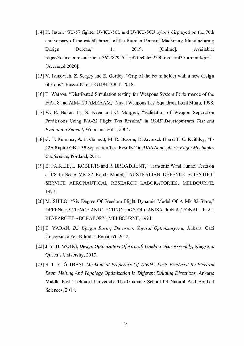
75
[14] H. Jason, “SU-57 fighter UVKU-50L and UVKU-50U pylons displayed on the 70th
anniversary of the establishment of the Russian Pennant Machinery Manufacturing
Design Bureau,” 11 2019. [Online]. Available:
https://k.sina.com.cn/article_3622879452_pd7f0c0dc02700tros.html?from=mil#p=1.
[Accessed 2020].
[15] V. Ivanovich, Z. Sergey and E. Gordey, “Grip of the beam holder with a new design
of stops”. Russia Patent RU184130U1, 2018.
[16] T. Watson, “Distributed Simulation testing for Weapons System Performance of the
F/A-18 and AIM-120 AMRAAM,” Naval Weapons Test Squadron, Point Mugu, 1998.
[17] W. B. Baker, Jr., S. Keen and C. Morgret, “Validation of Weapon Separation
Predictions Using F/A-22 Flight Test Results,” in USAF Developmental Test and
Evaluation Summit, Woodland Hills, 2004.
[18] G. T. Kummer, A. P. Gunnett, M. R. Besson, D. Javorsek II and T. C. Keithley, “F-
22A Raptor GBU-39 Separation Test Results,” in AIAA Atmospheric Flight Mechanics
Conference, Portland, 2011.
[19] B. PAIRLIE, L. ROBERTS and R. BROADBENT, “Transonic Wind Tunnel Tests on
a 1/8 th Scale MK-82 Bomb Model,” AUSTRALIAN DEFENCE SCIENTIFIC
SERVICE AERONAUTICAL RESEARCH LABORATORIES, MELBOURNE,
1977.
[20] M. SHILO, “Six Degree Of Freedom Flight Dynamic Model Of A Mk-82 Store,”
DEFENCE SCIENCE AND TECHNOLOGY ORGANISATION AERONAUTICAL
RESEARCH LABORATORY, MELBOURNE, 1994.
[21] E. YABAN, Bir Uçağın Basınç Duvarının Yapısal Optimizasyonu, Ankara: Gazi
Üniversitesi Fen Bilimleri Enstitüsü, 2012.
[22] J. Y. B. WONG, Design Optimization Of Aircraft Landing Gear Assembly, Kingston:
Queen’s University, 2017.
[23] S. T. Y˙İĞİTBAŞI, Mechanical Properties Of Tı6al4v Parts Produced By Electron
Beam Melting And Topology Optimization In Different Building Directions, Ankara:
Middle East Technical University The Graduate School Of Natural And Applied
Sciences, 2018.
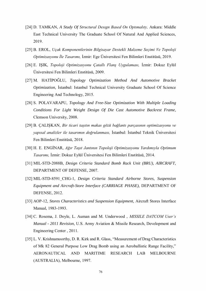
76
[24] D. TAMKAN, A Study Of Structural Desıgn Based On Optımalıty, Ankara: Middle
East Technical University The Graduate School Of Natural And Applied Sciences,
2019.
[25] B. EROL, Uçak Komponentlerinin Bilgisayar Destekli Malzeme Seçimi Ve Topoloji
Optimizasyonu İle Tasarımı, İzmir: Ege Üniversitesi Fen Bilimleri Enstitüsü, 2019.
[26] E. IŞIK, Topoloji Optimizasyonu Çatallı Flanş Uygulaması, İzmir: Dokuz Eylül
Üniversitesi Fen Bilimleri Enstitüsü, 2009.
[27] M. HATİPOĞLU, Topology Optimization Method And Automotive Bracket
Optimization, İstanbul: Istanbul Technical University Graduate School Of Science
Engineering And Technology, 2015.
[28] S. POLAVARAPU, Topology And Free-Size Optimization With Multiple Loading
Conditions For Light Weight Design Of Die Cast Automotive Backrest Frame,
Clemson University, 2008.
[29] B. ÇALIŞKAN, Bir ticari taşıtın makas gözü bağlantı parçasının optimizasyonu ve
yapısal analizler ile tasarımın doğrulanması, İstanbul: İstanbul Teknik Üniversitesi
Fen Bilimleri Enstitüsü, 2018.
[30] H. E. ENGİNAR, Ağır Taşıt Jantının Topoloji Optimizasyonu Yardımıyla Optimum
Tasarımı, İzmir: Dokuz Eylül Üniversitesi Fen Bilimleri Enstitüsü, 2014.
[31] MIL-STD-2088B, Design Criteria Standard Bomb Rack Unit (BRU), AIRCRAFT,
DEPARTMENT OF DEFENSE, 2007.
[32] MIL-STD-8591_CHG-1, Design Criteria Standard Airborne Stores, Suspension
Equipment and Aircraft-Store Interface (CARRIAGE PHASE), DEPARTMENT OF
DEFENSE, 2012.
[33] AOP-12, Stores Characteristics and Suspension Equipment, Aircraft Stores Interface
Manual, 1983-1993.
[34] C. Rosema, J. Doyle, L. Auman and M. Underwood , MISSILE DATCOM User’s
Manual - 2011 Revision, U.S. Army Aviation & Missile Research, Development and
Engineering Center , 2011.
[35] L. V. Krishnamoorthy, D. R. Kirk and R. Glass, “Measurement of Drag Characteristics
of Mk 82 General Purpose Low Drag Bomb using an Aeroballistic Range Facility,”
AERONAUTICAL AND MARITIME RESEARCH LAB MELBOURNE
(AUSTRALIA), Melbourne, 1997.
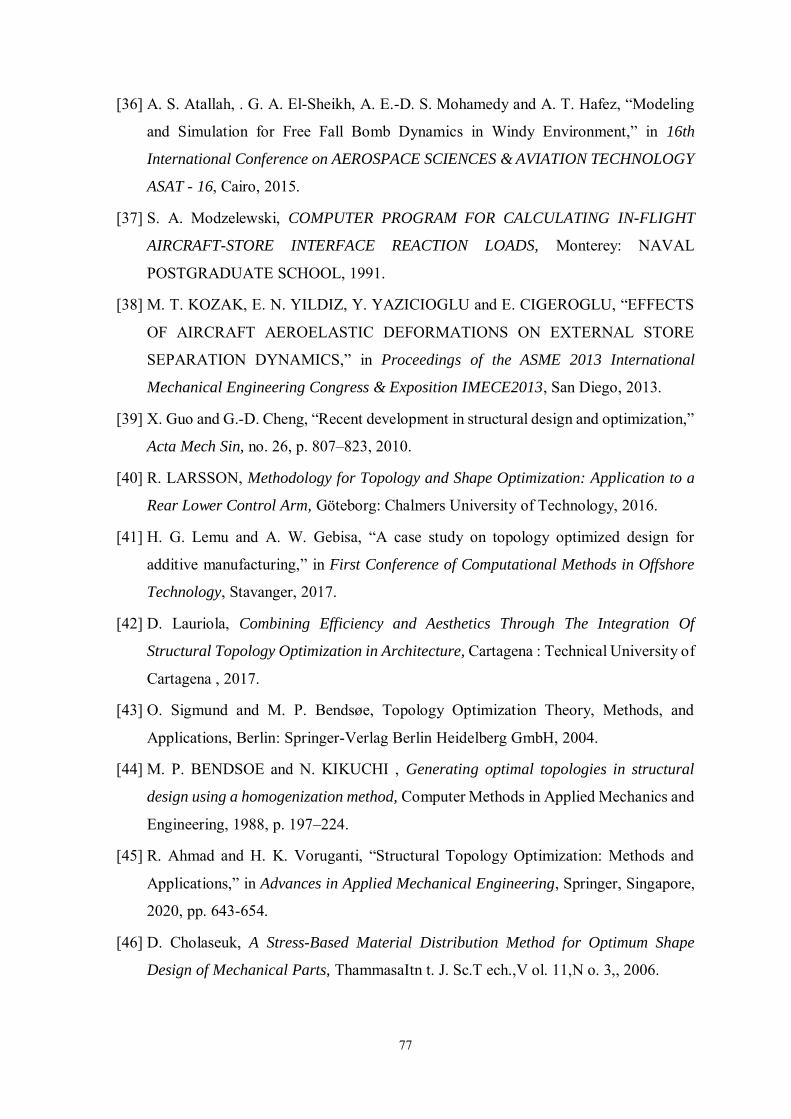
77
[36] A. S. Atallah, . G. A. El-Sheikh, A. E.-D. S. Mohamedy and A. T. Hafez, “Modeling
and Simulation for Free Fall Bomb Dynamics in Windy Environment,” in 16th
International Conference on AEROSPACE SCIENCES & AVIATION TECHNOLOGY
ASAT - 16, Cairo, 2015.
[37] S. A. Modzelewski, COMPUTER PROGRAM FOR CALCULATING IN-FLIGHT
AIRCRAFT-STORE INTERFACE REACTION LOADS, Monterey: NAVAL
POSTGRADUATE SCHOOL, 1991.
[38] M. T. KOZAK, E. N. YILDIZ, Y. YAZICIOGLU and E. CIGEROGLU, “EFFECTS
OF AIRCRAFT AEROELASTIC DEFORMATIONS ON EXTERNAL STORE
SEPARATION DYNAMICS,” in Proceedings of the ASME 2013 International
Mechanical Engineering Congress & Exposition IMECE2013, San Diego, 2013.
[39] X. Guo and G.-D. Cheng, “Recent development in structural design and optimization,”
Acta Mech Sin, no. 26, p. 807–823, 2010.
[40] R. LARSSON, Methodology for Topology and Shape Optimization: Application to a
Rear Lower Control Arm, Göteborg: Chalmers University of Technology, 2016.
[41] H. G. Lemu and A. W. Gebisa, “A case study on topology optimized design for
additive manufacturing,” in First Conference of Computational Methods in Offshore
Technology, Stavanger, 2017.
[42] D. Lauriola, Combining Efficiency and Aesthetics Through The Integration Of
Structural Topology Optimization in Architecture, Cartagena : Technical University of
Cartagena , 2017.
[43] O. Sigmund and M. P. Bendsøe, Topology Optimization Theory, Methods, and
Applications, Berlin: Springer-Verlag Berlin Heidelberg GmbH, 2004.
[44] M. P. BENDSOE and N. KIKUCHI , Generating optimal topologies in structural
design using a homogenization method, Computer Methods in Applied Mechanics and
Engineering, 1988, p. 197–224.
[45] R. Ahmad and H. K. Voruganti, “Structural Topology Optimization: Methods and
Applications,” in Advances in Applied Mechanical Engineering, Springer, Singapore,
2020, pp. 643-654.
[46] D. Cholaseuk, A Stress-Based Material Distribution Method for Optimum Shape
Design of Mechanical Parts, ThammasaItn t. J. Sc.T ech.,V ol. 11,N o. 3,, 2006.
78
[47] S. OSHER and J. A. SETHIAN, “Fronts propagating with curvature-dependent speed:
Algorithms based on Hamilton-Jacobi formulations,” JOURNAL OF
COMPUTATIONAL PHYSICS, vol. (1), no. 79, pp. 12-49 , 1988.
[48] P. Tanskanen, “A multiobjective and fixed elements based modification of the
evolutionary structural optimization method,” Computer Methods in Applied
Mechanics and Engineering, Vols. 1-3, no. 196, pp. 76-90, 2006.
[49] D. Systèmes, SIMULIA TOSCA STRUCTURE THE STRUCTURAL OPTIMIZATION
SYSTEM, 3DEXPERIENCE Company.
79
APPENDICES
APPENDIX A: Model Figures APPENDIX B: Optimization Cycles *.log file
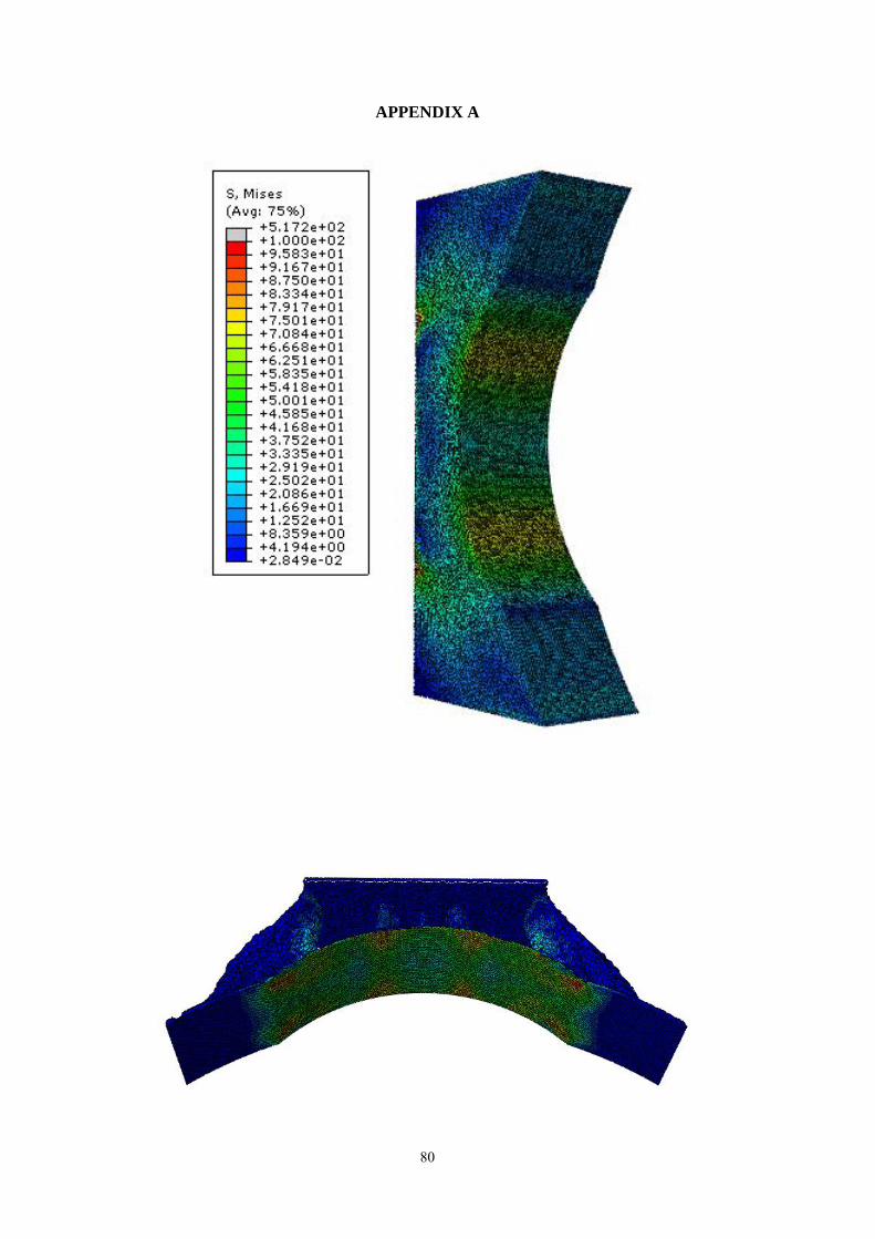
80
APPENDIX A
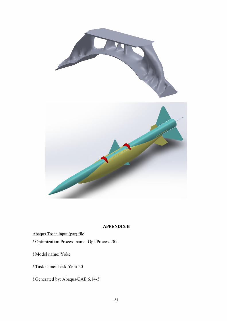
81
APPENDIX B
Abaqus Tosca input (par) file
! Optimization Process name: Opt-Process-30a
! Model name: Yoke
! Task name: Task-Yeni-20
! Generated by: Abaqus/CAE 6.14-5
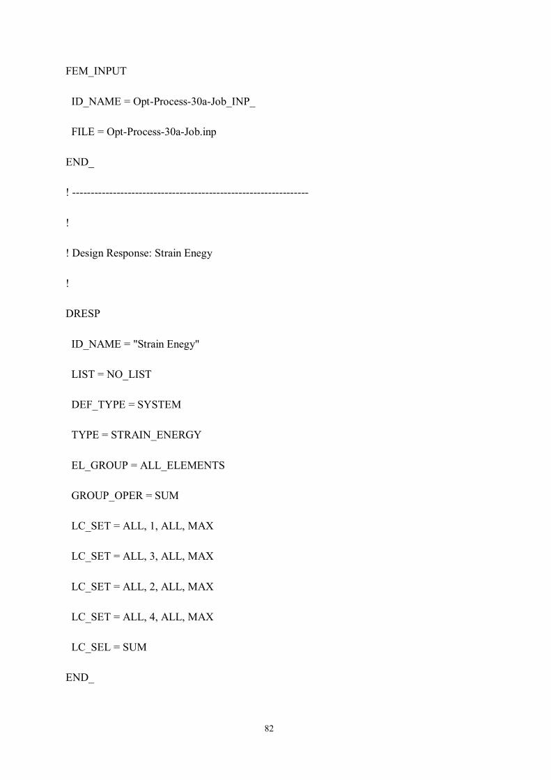
82
FEM_INPUT
ID_NAME = Opt-Process-30a-Job_INP_
FILE = Opt-Process-30a-Job.inp
END_
! ----------------------------------------------------------------
!
! Design Response: Strain Enegy
!
DRESP
ID_NAME = "Strain Enegy"
LIST = NO_LIST
DEF_TYPE = SYSTEM
TYPE = STRAIN_ENERGY
EL_GROUP = ALL_ELEMENTS
GROUP_OPER = SUM
LC_SET = ALL, 1, ALL, MAX
LC_SET = ALL, 3, ALL, MAX
LC_SET = ALL, 2, ALL, MAX
LC_SET = ALL, 4, ALL, MAX
LC_SEL = SUM
END_
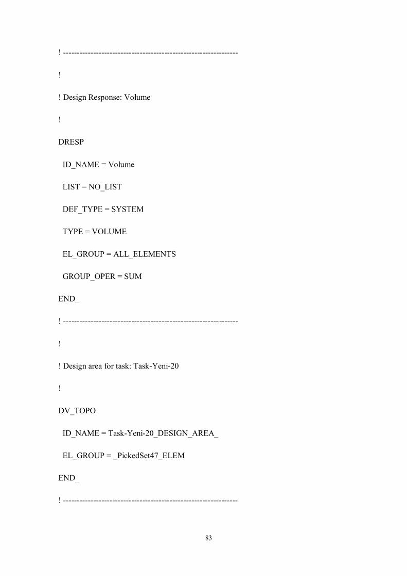
83
! ----------------------------------------------------------------
!
! Design Response: Volume
!
DRESP
ID_NAME = Volume
LIST = NO_LIST
DEF_TYPE = SYSTEM
TYPE = VOLUME
EL_GROUP = ALL_ELEMENTS
GROUP_OPER = SUM
END_
! ----------------------------------------------------------------
!
! Design area for task: Task-Yeni-20
!
DV_TOPO
ID_NAME = Task-Yeni-20_DESIGN_AREA_
EL_GROUP = _PickedSet47_ELEM
END_
! ----------------------------------------------------------------
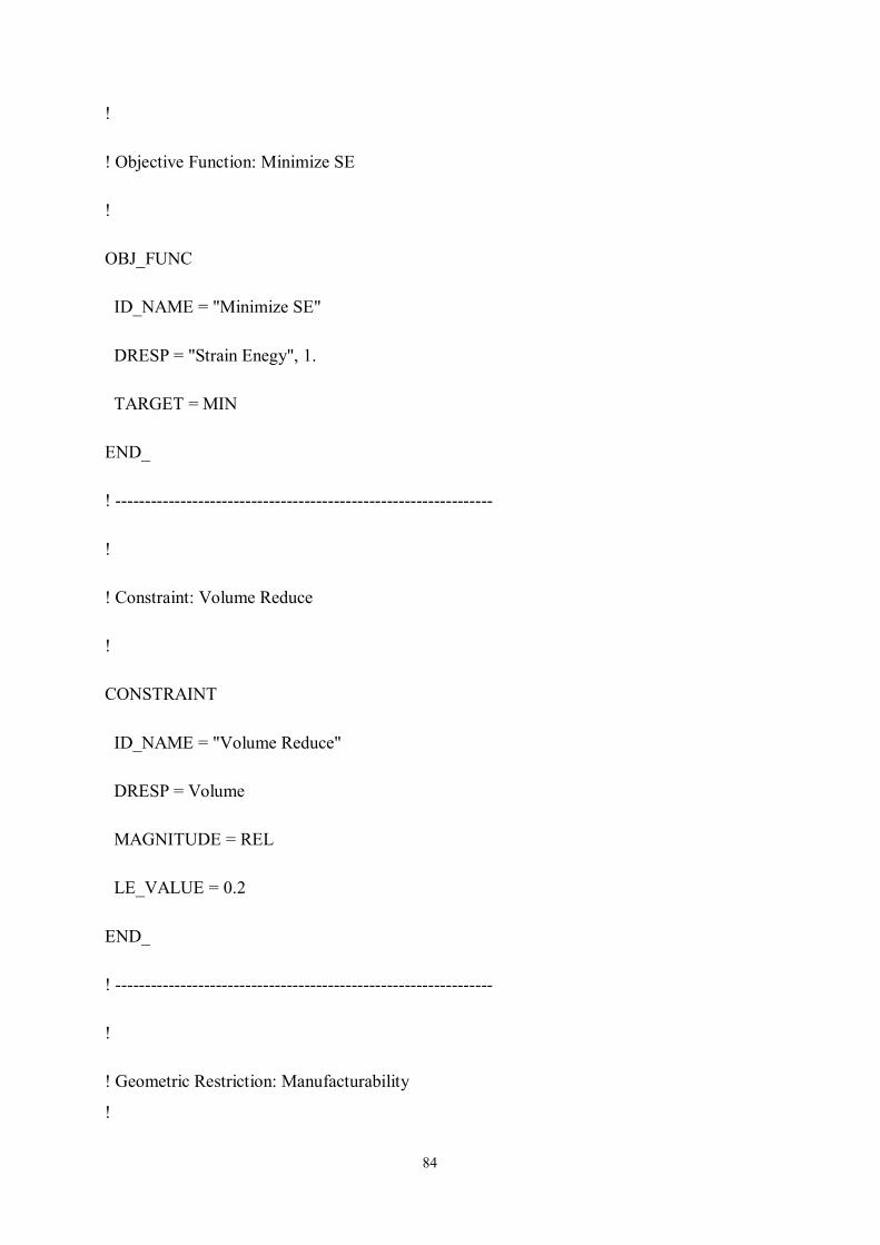
84
!
! Objective Function: Minimize SE
!
OBJ_FUNC
ID_NAME = "Minimize SE"
DRESP = "Strain Enegy", 1.
TARGET = MIN
END_
! ----------------------------------------------------------------
!
! Constraint: Volume Reduce
!
CONSTRAINT
ID_NAME = "Volume Reduce"
DRESP = Volume
MAGNITUDE = REL
LE_VALUE = 0.2
END_
! ----------------------------------------------------------------
!
! Geometric Restriction: Manufacturability
!
85
DVCON_TOPO
ID_NAME = Manufacturability
EL_GROUP = _PickedSet44_ELEM
CHECK_TYPE = CAST
PULL_DIR = 0., 0. , 1.
ANGLE = 0.
CHECK_GROUP = _PickedSet44_ELEM
MID_PLANE = AUTO
PULL_CS = CS_0
CREATE_PULL_GROUP = NO
END_
! ----------------------------------------------------------------
!
! Task: Task-Yeni-20
!
OPTIMIZE
ID_NAME = Task-Yeni-20
DV = Task-Yeni-20_DESIGN_AREA_
OBJ_FUNC = "Minimize SE"
DVCON = Manufacturability
CONSTRAINT = "Volume Reduce"
86
STRATEGY = TOPO_SENSITIVITY
END_
OPT_PARAM
ID_NAME = Task-Yeni-20_OPT_PARAM_
OPTIMIZE = Task-Yeni-20
AUTO_FROZEN = BOTH
DENSITY_UPDATE = NORMAL
DENSITY_LOWER = 0.001
DENSITY_UPPER = 1.
DENSITY_MOVE = 0.25
MAT_PENALTY = 3.
STOP_CRITERION_LEVEL = BOTH
STOP_CRITERION_OBJ = 0.001
STOP_CRITERION_DENSITY = 0.005
STOP_CRITERION_ITER = 4
SUM_Q_FACTOR = 6.
END_
STOP
ID_NAME = Task-Yeni-20_GLOBAL_STOP_CONDITION_
ITER_MAX = 50
END_
87
CONFIG
${fe_solver_add_call} = "message messaging_mechanism=DIRECT
listener_name=DESKTOP-QKSN7OI listener_resource=13996 direct_port=52020
memory=90% cpus=8";
add_move_per_iter_list("ever", "SAVE.odb", "*.odb");
add_move_per_iter_list("ever", "SAVE.msg", "*.msg");
add_move_per_iter_list("ever", "SAVE.dat", "*.dat");
add_move_per_iter_list("ever", "SAVE.sta", "*.sta");
END_
EXIT