Embed Size (px)
Citation preview
DEUTSCH
Einbauanleitung
5.2. Anschluss der Ausgangsklemmen (Abb. 1 (2))Verwenden Sie die Schraubklemmen „+“ und „-“, um den 24Vdc-Anschluss herzustellen. Am Ausgang stehen 24Vdc zur Verfügung. Die Ausgangsspannung kann am Potentiometer zwischen 22 und 28Vdc eingestellt werden. Die grüne LED “DC OK” zeigt die korrekte Funktion des Ausgangs an (Abb. 1 (4)). Das Gerät verfügt über einen Kurzschluss-, Überlast- und Überspannungsschutz, der auf 35Vdc begrenzt ist.
5.3. AusgangskennlinieDas Gerät funktioniert normal, solange die Netz- und Lastbedingungen im Betriebsbereich des Geräts liegen. Im Fall eines Kurzschlusses oder einer Überlast fallen Ausgangsspannung und –strom ab (bei IÜberlast bzw. IKurzschluss > IÜberstrom (150%)). Die Sekundärspannung wird dabei so lange abgesenkt, bis der sekundärseitige Kurzschluss oder die Überlast behoben sind.
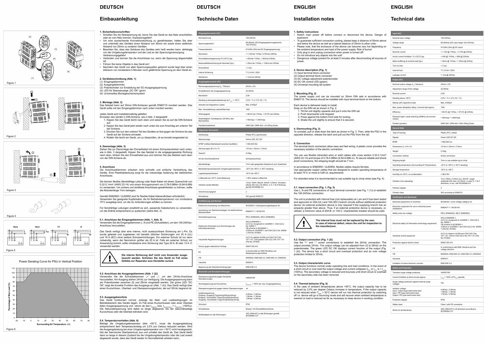
5.4. Temperaturverhalten (Abb. 6)Beträgt die Umgebungstemperatur über +50°C, muss die Ausgangsleistung entsprechend dem Temperaturanstieg um 2,5% pro Celsius reduziert werden. Wird die Ausgangsleistung bei einer Umgebungstemperatur von > 50°C nicht herabgesetzt, löst der thermische Überlastschutz aus und schaltet das Gerät ab. Das Gerät bleibt dann so lange in diesem Zustand bis die Umgebungstemperatur oder die Last soweit abgesenkt wurde, dass das Gerät wieder im Normalbetrieb arbeiten kann.
Die interne Sicherung darf nicht vom Anwender ausge-tauscht werden. Schicken Sie das Gerät im Fall eines Defekts zur Reparatur zum Hersteller zurück.
ENGLISH
Installation notes
5.2. Output connection (Fig. 1 (2))Use the “+” and “-“ screw connections to establish the 24Vdc connection. The output provides 24Vdc. The output voltage can be adjusted from 22 to 28Vdc on the potentiometer. The green LED DC OK displays correct function of the output (Fig. 1 (4)). The device has a short circuit and overload protection and an over voltage protection limited to 35Vdc.
5.3. Output characteristic curveThe device functions normal under operating line and load conditions. In the event of a short circuit or over load the output voltage and current collapses (IO/L or IS/C is > Isurge (150%)). The secondary voltage is reduced and bounces until short circuit or overload on the secondary side has been removed.
5.4. Thermal behavior (Fig. 6)In the case of ambient temperatures above +50°C, the output capacity has to be reduced by 2.5% per degree Celsius increase in temperature. If the output capacity is not reduced when TAmb > 50°C device will run into thermal protection by switching off i.e. device will go in bouncing mode and will recover when ambient temperature is lowered or load is reduced as far as necessary to keep device in working condition.
The internal fuse must not be replaced by the user. In case of internal defect, return the unit for inspection to the manufacturer.
ENGLISH
Technical data
Input (AC)
Nominal input voltage 100-240Vac
Voltage range 85-264Vac (DC input range 120-375Vdc)
Frequency 47-63Hz (0Hz @ DC input)
Nominal current < 1.10A @ 115Vac, < 0.70A @ 230Vac
Inrush current limitation. I2t (+25°C) typ. < 40A @ 115Vac, < 80A @ 230Vac
Mains buffering at nominal load (typ.) > 20ms @ 115Vac, > 125ms @ 230Vac
Turn-on time < 3 sec.
Internal fuse T 3.15 AH / 250V
Leakage current < 1mA @ 240Vac
Output (DC)
Nominal output voltage UN / tolerance 24Vdc ± 2%
Adjustment range of the voltage 22-28Vdc
Nominal current 2.5A
Derating above +50°C 2.5% / °C (< 0°C 2% / °C)
Startup with capacitive loads Max. 8,000µF
Max. power dissipation idling / nominal load approx. 10W
Efficiency > 86.0% @ 115Vac, > 87.0% @ 230Vac
Residual ripple / peak switching (20MHz) (at nominal values) < 50mVpp / < 240mVpp
Parallel operation DRR-20A / DRR-40A / With ORing Diode
General Data
Type of housing Plastic (PC), closed
Signals Green LED DC OK
MTBF > 800,000 hrs.
Dimensions (L x W x H) 121mm x 32mm x 113mm
Weight 0.33kg
Connection method Screw connection
Stripping length 7mm or use suitable lug to crimp
Operating temperature (Surrounding Air Temperature) -20°C to +80°C (> 50°C derating)
Storage temperature -25°C to +85°C
Humidity at +25°C, no condensation < 95% RH
Vibration (non-operating)10 to 150Hz, 0.35mm acc. 50m/S², single amplitude (5G max.) for 90min. in each X, Y & Z directions, in acc. with IEC60068-2-6
Pollution degree 2
Climatic class 3K3 according to EN60721
Certification and Standards
Electrical equipments of machines IEC60204-1 (over voltage category III)
Electronic equipment for use in electrical power installations EN62477-1 / IEC62103
Safety entry low voltage PELV (EN60204), SELV (EN60950)
Electrical safety (of information technology equipment)
SIQ to EN60950-1,UL/C-UL recognized to UL60950-1, CSA C22.2 No. 60950-1,CB scheme to IEC60950-1,cCSAus to UL60950-1 and CSA C22.2 No. 60950-1 (File No.181564)
Industrial control equipmentUL/C-UL listed to UL508 and CSA C22.2 No. 107.1-01, CSA to CSA C22.2 No.107.1-01 (File No.181564)
Protection against electric shock DIN57100-410
CE In conformance with EMC directive and low voltage directive
ITE EN55022, EN61000-3-2, EN61000-3-3, EN55024
Industrial EN55011
Limitation of mains harmonic currents EN61000-3-2
Safety and Protection
Transient surge voltage protection VARISTOR
Current limitation at short-circuits approx. Isurge = 150% of Pomax typically
Surge voltage protection against internal surge voltages Yes
Isolation voltage:Input / output (type test/routine test)Input / PE (type test/routine test)Output / PE (type test/routine test)
4.0KVac / 3.0KVac1.5KVac / 1.5KVac1.5KVac / 0.5KVac
Protection degree IPX0
Safety class Class I with PE connection
Shock (in all directions) 30G (300m/S²) in all directions according to IEC60068-2-27
DEUTSCH
Technische Daten
Eingangskennwerte (AC)
Nennspannung 100-240Vac
Spannungsbereich 85-264Vac (DC-Eingangsspannungsbereich 120-375Vdc)
Frequenzbereich 47-63Hz (0Hz bei DC Eingangsspannung)
Nennstrom < 1,10A bei 115Vac, 0,70A bei 230Vac
Einschaltstrombegrenzung I²t (+25°C) typ. < 40A bei 115Vac, < 80A bei 230Vac
Netzausfallüberbrückung bei Nennlast (typ.) > 20ms bei 115Vac, > 125ms bei 230Vac
Einschaltzeit < 3 sec.
Interne Sicherung T 3,15 AH / 250V
Ableitstrom < 1mA bei 240Vac
Ausgangskennwerte (DC)
Nennausgangsspannung UN / Toleranz 24Vdc ± 2%
Einstellbereich der Ausgangsspannung 22-28Vdc
Nennstrom 2,5A
Derating (Leistungsherabsetzung) ab Tamb > +50°C 2,5% / °C (< 0°C 2% / °C)
Anlaufen bei Kapazitiven Lasten Max. 8.000µF
Max. Verlustleistung Leerlauf/Nennlast 10W
Wirkungsgrad > 86,0% bei 115Vac, > 87,0% bei 230Vac
Restwelligkeit / Schaltspitzen (20 MHz) (bei Nennwerten) < 50mVpp / < 240mVpp
Parallelschaltbarkeit DRR-20A / DRR-40A / mit ORing Diode
Allgemeine Kennwerte
Gehäusetyp Plastik (PC), geschlossen
Statusanzeige Grüne LED „DC OK“
MTBF (mittlere Betriebszeit zwischen Ausfällen) > 800.000 Std.
Abmessungen (B x H x T) 121mm x 32mm x 113mm
Gewicht 0,33kg
Art der Anschlussklemme Schraubanschluss
Abisolierlänge 7mm oder geeigneter Kabelschuh zum Quetschen
Betriebstemperaturbereich (Umgebungstemperatur) -20°C bis +80°C (> 50°C derating)
Lagertemperaturbereich -25°C bis +85°C
Luftfeuchte bei +25°C, keine Betauung < 95% relative Luftfeuchte
Vibration (außer Betrieb)10 bis 150Hz, Beschl. 50mS², 0,35mm Einzelam-plitude (5G max.) für 90min. in X, Y & Z Richtung, gemäß IEC60068-2-6
Verschmutzungsgrad 2
Klimaklasse 3K3 gemäß EN60721
Zertifizierung und Normen
Elektrische Ausrüstung von Maschinen IEC60204-1 (Überspannungskategorie III)
Ausrüstung von Starkstromanlagen mit elektronischen Betriebsmitteln EN62477-1 / IEC62103
Schutzkleinspannung PELV (EN60204), SELV (EN60950)
Elektrische Sicherheit (von Einrichtungen der Informationstechnik)
SIQ to EN60950-1,UL/C-UL recognized to UL60950-1, CSA C22.2 No. 60950-1,CB scheme to IEC60950-1,cCSAus to UL60950-1 und CSA C22.2 No. 60950-1 (File No.181564)
Industrielle RegeleinrichtungenUL/C-UL gelistet UL508 und CSA C22.2 No. 107.1-01, CSA gelistet CSA C22.2 No.107.1-01 (File No.181564)
Schutz gegen elektrischen Schlag DIN57100-410
EC In Konformität zur EMV-Richtlinie und Niederspannungsrichtlinie
ITE EN55022, EN61000-3-2, EN61000-3-3, EN55024
Industrial EN55011
Begrenzung der Netzoberschwingungen EN61000-3-2
Sicherheit und Schutzeinrichtungen
Überspannungsschutz gegen transienteÜberspannungen VARISTOR
Strombegrenzung bei Kurzschluss IÜberstrom = 150% der max. Ausgangsleistung
Überspannungsschutz gegen interne Überspannungen Ja
IsolationsspannungEingang / Ausgang (Typprüfung/Stückprüfung)Eingang / Schutzleiter (Typprüfung/Stückprüfung)Ausgang / Schutzleiter (Typprüfung/Stückprüfung)
4,0KVac / 3,0KVac1,5KVac / 1,5KVac1,5KVac / 0,5KVac
Schutzart IPX0
Schutzklasse Klasse I mit Schutzleiteranschluss
Stoßfestigkeit (in alle Richtungen) 30G (300m/S²) in alle Richtungen gemäß IEC60068-2-27
1. Sicherheitsvorschriften• SchaltenSiedieNetzspannungab,bevorSiedasGerätandasNetzanschließen oder es vom Netz trennen. Explosionsgefahr!• Um eine ausreichende Konvektionskühlung zu gewährleisten, halten Sie ober und unterhalb des Gerätes einen Abstand von 50mm ein sowie einen seitlichen Abstand von 20mm zu anderen Geräten.• BeachtenSie,dassdasGehäusedesGerätessehrheißwerdenkann,abhängig von der Umgebungstemperatur und der Last an der Spannungsversorgung. Verbrennungsgefahr!• VerbindenundtrennenSiedieAnschlüssenur,wenndieSpannungabgeschaltet ist!• FührenSiekeineObjekteindasGerätein!• NachdemdasGerätvonallenSpannungsquellengetrenntwurdeliegtübereinen Zeitraum von mindestens 5 Minuten noch gefährliche Spannung an dem Gerät an.
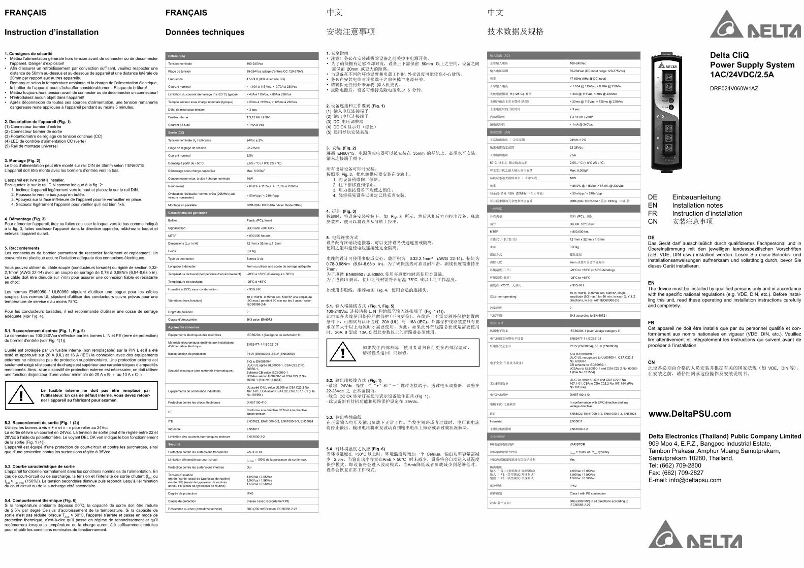
2. Gerätebeschreibung (Abb. 1)(1) Eingangsklemmen(2) Ausgangsklemmen(3) Potentiometer zur Einstellung der DC-Ausgangsspannung(4) LED für Statusanzeige „DC OK“ (grün)(5) Universelles Montageschienensystem
3. Montage (Abb. 2)Das Netzteil kann auf 35mm DIN-Schienen gemäß EN60715 montiert werden. Das Gerät sollte mit den Eingangsklemmen nach unten montiert werden.
Jedes Gerät wird installationsfertig geliefert.Einrasten des Geräts in DIN-Schiene, wie in Abb. 2 dargestellt: 1. Kippen Sie das Gerät leicht nach oben und setzen Sie es auf die DIN-Schiene auf. 2. Kippen Sie das Gerät jetzt wieder nach unten bis zum Anschlag am unteren Teil der Schiene. 3. Drücken Sie nun den unteren Teil des Gerätes so fest gegen die Schiene bis das Gerät auf der Schiene einrastet. 4. Rütteln Sie leicht am Gerät, um zu überprüfen, ob es korrekt eingerastet ist.
4. Demontage (Abb. 3)Ziehen Sie zur Demontage den Einrasthebel mit einem Schraubendreher nach unten, wie in Abb. 3 dargestellt. Kippen Sie das Netzteil in die entgegengesetzte Richtung nach oben, klinken Sie den Einrasthebel aus und nehmen Sie das Netzteil nach oben von der DIN-Schiene ab.
5. AnschlussDie Anschlussklemmen erlauben eine schnelle und einfache Verdrahtung des Geräts. Eine Plastikabdeckung sorgt für die notwendige Isolierung der elektrischen Anschlüsse.
Siekönnenflexible(feindrähtigeLeitung)oderfesteKabelmiteinemQuerschnittvon0,32-2,1mm² (AWG 22-14) und einem Anzugsmoment von 0,78-0,98Nm (6,94-8,68lb in) verwenden. Um sichere und stoßfeste Anschlüsse gewährleisten zu können, sollte die Abisolierlänge 7mm betragen.
GemäßEN60950/UL60950sindfürflexibleKabelAderendhülsenerforderlich.Verwenden Sie geeignete Kupferkabel, die für Betriebstemperaturen von mindestens 75°C ausgelegt sind, um die UL-Anforderungen erfüllen zu können.
FürfeindrähtigeLeitungenempfiehlt es sich, passende Kabelschuhe zu verwenden, um die Drähte entsprechend zu quetschen (siehe Abb. 4).
5.1. Anschluss der Eingangsklemmen (Abb. 1, Abb. 5)Verwenden Sie die Eingangsklemmen L, N und PE (Schutzleiter), um den 100-240Vac-Anschluss herzustellen.
Das Gerät verfügt über eine interne, nicht austauschbare Sicherung am L-Pin. Es wurde getestet und zugelassen mit handels üblichen Sicherungen von 20 A (UL) und 16 A (IEC) ohne weitere Schutzeinrichtungen. Ein externer Schutz ist nur dann notwendig, wenn der Nennstrom größer als 20 A ist. Falls ein externer Schutz zur Anwendung kommt, sollte mindestens eine Sicherung des Typs 20 A -B oder 13 A -C verwendet werden.
1. Safety instructions• Switch main power off before connect or disconnect the device. Danger of explosion!• Toguaranteesufficientconvectioncooling,pleasekeepadistanceof50mmabove and below the device as well as a lateral distance of 20mm to other units.• Pleasenote,thattheenclosureofthedevicecanbecomeveryhotdependingon the ambient temperature and load of the power supply. Risk of burns!• Onlypluginandunplugconnectorswhenpoweristurnedoff!• Donotintroduceanyobjectsintotheunit!• Dangerousvoltagepresentforatleast5minutesafterdisconnectingallsourcesof power.
2. Device description (Fig. 1)(1) Input terminal block connector(2) Output terminal block connector(3) DC voltage adjustment potentiometer(4) DC OK control LED (green)(5) Universal mounting rail system
3. Mounting (Fig. 2)The power supply unit can be mounted on 35mm DIN rails in accordance with EN60715. The device should be installed with input terminal block on the bottom.
Each device is delivered ready to install.Snap on the DIN rail as shown in Fig. 2: 1. Tilt the unit slightly upwards and put it onto the DIN rail. 2. Push downwards until stopped. 3. Press against the bottom front side for locking. 4. Shake the unit slightly to ensure that it is secured.
4. Dismounting (Fig. 3)To uninstall, pull or slide down the latch as shown in Fig. 3. Then, slide the PSU in the opposite direction, release the latch and pull out the PSU from the rail.
5. ConnectionThe terminal block connectors allow easy and fast wiring. A plastic cover provides the necessary isolation of the electric connection.
Youcanuseflexible(strandedwire)orsolidcableswithcrosssection0.32-2.1mm²(AWG 22-14) and torque of 0.78-0.98Nm (6.94-8.68lb in). To secure reliable and shock proof connections, the stripping length should be 7 mm.
InaccordancetoEN60950/UL60950,flexiblecablesrequireferrules.Use appropriate copper cables that are designed to sustain operating temperature of atleast75°CormoretofulfilULrequirements.
For stranded wires it is recommended to use suitable lug to crimp wires (see Fig. 4).
5.1. Input connection (Fig. 1, Fig. 5)Use L, N and PE connections of input terminal connector (see Fig. 1 (1)) to establish the 100-240Vac connection.
The unit is protected with internal fuse (not replaceable) at L pin and it has been tested and approved on 20A (UL) and 16A (IEC) branch circuits without additional protection device. An external protection device is only required if the supplying branch has an ampacity greater than above. Thus, if an external protective device is necessary, or, utilized, a minimum value of 20A B- or 13A C- characteristic breaker should be used.
Figure 2
Figure 3
(1)
(2)
(5)
(4)
(3)
Figure 1
0
10
20
30
40
50
60
70
80
90
100
110
-20 -10 0 10 20 30 40 50 60 70 80
Perc
enta
ge o
f Max
Loa
d (%
)
Surrounding Air Temperature (oC)
Figure 6
Power Derating Curve for PSU in Vertical Position
Figure 4
Figure 5
LNPE
L N PE
TN-SLPEN
TN-C
+
LN
TT IT
L N PE+
L N PE+
LN
L N PE+
Manual_CliQ_60W1Pplastic_D0116888_Rev.08_090816.indd 1 8/9/2016 11:29:41 AM
Delta CliQ Power Supply System 1AC/24VDC/2.5ADRP024V060W1AZ
DE EinbauanleitungEN Installation notesFR Instruction d’installationCN 安装注意事项
www.DeltaPSU.com
Delta Electronics (Thailand) Public Company Limited 909 Moo 4, E.P.Z., Bangpoo Industrial Estate, Tambon Prakasa, Amphur Muang Samutprakarn, Samutprakarn 10280, Thailand. Tel: (662) 709-2800Fax: (662) 709-2827E-mail: [email protected]
DEDasGerät darf ausschließlich durch qualifiziertes Fachpersonal und inÜbereinstimmung mit den jeweiligen landesspezifischen Vorschriften(z.B. VDE, DIN usw.) installiert werden. Lesen Sie diese Betriebs- und Installationsanweisungen aufmerksam und vollständig durch, bevor Sie dieses Gerät installieren.
ENThedevicemustbeinstalledbyqualifiedpersonsonlyandinaccordancewiththespecificnationalregulations(e.g.VDE,DIN,etc.).Beforeinstal-ling this unit, read these operating and installation instructions carefully and completely.
FRCet appareil ne doit être installé que par du personnel qualifié et con-formément aux nomrs nationales en vigueur (VDE, DIN, etc.). Veuillez lire attentivement et intégralement les instructions qui suivent avant de procéder à l’installation
CN此设备必须由合格的人员安装并根据有关的国家法规(如 VDE, DIN 等)。在安装之前,请仔细阅读这份操作及安装说明书。
FRANÇAIS
Données techniques
Entrée (CA)
Tension nominale 100-240Vca
Plage de tension 85-264Vca (plage d’entrée CC 120-375V)
Fréquence 47-63Hz (0Hz à l’entrée CC)
Courant nominal < 1,10A à 115 Vca, < 0,70A à 230Vca
Limitation du courant démarrage I2t (+25°C) typique < 40A à 115Vca, < 80A à 230Vca
Tampon secteur sous charge nominale (typique) > 20ms à 115Vca, > 125ms à 230Vca
Délai de mise sous tension < 3 sec.
Fusible interne T 3,15 AH / 250V
Courant de fuite < 1mA à Vca
Sortie (CC)
Tension nominale UN / tolérance 24Vcc ± 2%
Plage de réglage de tension 22-28Vcc
Courant nominal 2,5A
Derating à partir de +50°C 2,5% / °C (< 0°C 2% / °C)
Démarrage sous charge capacitive Max. 8.000µF
Consommation max. à vide / charge nominale 10W
Rendement > 86,0% à 115Vca, > 87,0% à 230Vca
Ondulation résiduelle / comm. crête (20MHz) (aux valeurs nominales) < 50mVpp / < 240mVpp
Montage en parallèle DRR-20A / DRR-40A / Avec Diode ORing
Caractéristiques générales
Boîtier Plastic (PC), fermé
Signalisation LED verte «DC OK»
MTBF > 800.000 heures
Dimensions (L x l x H) 121mm x 32mm x 113mm
Poids 0,33kg
Type de connexion Bornes à vis
Longueur à dénuder 7mm ou utiliser une cosse de serrage adéquate
Température de travail (température d’environnement) -20°C à +80°C (Derating à > 50°C)
Température de stockage -25°C à +85°C
Humidité à 25°C, sans condensation < 95% HR
Vibrations (hors fonction)10 à 150Hz, 0,35mm acc. 50m/S² une amplitude (5G max.) pendant 90 min sur les 3 axes - selon IEC60068-2-6
Degré de pollution 2
Classe d’atmosphère 3K3 selon EN60721
Agréments et normes
Equipements électriques des machines IEC60204-1 (Catégorie de surtension III)
Matériels électroniques destinés aux installations d’alimentation électrique EN62477-1 / IEC62103
Basse tension de protection PELV (EN60204), SELV (EN60950)
Sécurité électrique (des matériels informatiques)
SIQ to EN60950-1,UL/C-UL agrée UL60950-1, CSA C22.2 No. 60950-1,Schéma CB selon IEC60950-1 cCSAus selon UL60950-1 et CSA C22.2 No. 60950-1 (File No.181564)
Equipements de commande industrielsUL agréé C-UL selon UL508 et CSA C22.2 No. 107.1-01, CSA selon CSA C22.2 No.107.1-01 (File No.181564)
Protection contre les chocs électriques DIN57100-410
CE Conforme à la directive CEM et à la directive basse tension
ITE EN55022, EN61000-3-2, EN61000-3-3, EN55024
Industrial EN55011
Limitation des courants harmoniques secteurs EN61000-3-2
Sécurité
Protection contre les surtensions transitoires VARISTOR
Limitation d’intensité sur court-circuit Ide crête = 150% de la puissance de sortie max.
Protection contre les surtensions internes Oui
Tension d’isolationentrée / sortie (essai de type/essai de routine)entrée / PE (essai de type/essai de routine)sortie / PE (essai de type/essai de routine)
4,0KVca / 3,5KVca1,5KVca / 1,5KVca1,5KVca / 0,5KVca
Degrée de protection IPX0
Classe de protection Classe I avec raccordement PE
Résistance au choc (omnidirectionnelle) 30G (300 m/S²) selon IEC60068-2-27
FRANÇAIS
Instruction d’installation
5.2. Raccordement de sortie (Fig. 1 (2))Utilisez les bornes à vis « + » et « - » pour relier au 24Vcc.La sortie délivre un courant en 24Vcc. La tension de sortie peut être réglée entre 22 et 28Vcc à l’aide du potentiomètre. Le voyant DEL OK vert indique le bon fonctionnement de la sortie (Fig. 1 (4)).L’appareil est équipé d’une protection de court-circuit et contre les surcharges, ainsi que d’une protection contre les surtensions réglée à 35Vcc.
5.3. Courbe caractéristique de sortieL’appareil fonctionne normalement dans les conditions nominales de l’alimentation. En cas de court-circuit ou de surcharge, la tension et l’intensité de sortie chutent (IO/L ou IS/C > Ide crête (150%)). La tension secondaire diminue puis rebondit jusqu’à l’élimination du court circuit ou de la surcharge côté secondaire.
5.4. Comportement thermique (Fig. 6)Si la température ambiante dépasse 50°C, la capacité de sortie doit être réduite de 2,5% par degré Celsius d’accroissement de la température. Si la capacité de sortie n’est pas réduite lorsque TAmb > 50°C, l’appareil s’arrête et passe en mode de protection thermique, c’est-à-dire qu’il passe en régime de rebondissement et qu’il redémarrera lorsque la températureou la chargeauront été suffisamment réduitespour rétablir les conditions nominales de fonctionnement.
Le fusible interne ne doit pas être remplacé par l’utilisateur. En cas de défaut interne, vous devez retour-ner l’appareil au fabricant pour examen.
1. Consignes de sécurité•Mettezl’alimentationgénéralehorstensionavantdeconnecteroudedéconnecter l’appareil. Danger d’explosion!• Afind’assurerunrefroidissementparconvectionsuffisant,veuillezrespecterune distance de 50mm au-dessus et au-dessous de appareil et une distance latérale de 20mm par rapport aux autres appareils.• Remarque:selonlatempératureambianteetlachargedel’alimentationélectrique, le boîtier de l’appareil peut s’échauffer considérablement. Risque de brûlure!• Metteztoujourshorstensionavantdeconnecteroudedéconnecterunconnecteur!• N’introduisezaucunobjetdansl’appareil!• Aprèsdéconnexiondetoutessessourcesd’alimentation,unetensionrémanente dangereuse reste appliquée à l’appareil pendant au moins 5 minutes.
2. Description de l’appareil (Fig. 1)(1) Connecteur bornier d’entrée(2) Connecteur bornier de sortie(3) Potentiomètre de réglage de tension continue (CC)(4) LED de contrôle d’alimentation CC (verte)(5) Rail de montage universel
3. Montage (Fig. 2)Le bloc d’alimentation peut être monté sur rail DIN de 35mm selon l’ EN60715.L’appareil doit être monté avec les borniers d’entrée vers le bas.
L’appareil est livré prêt à installer. EncliquetezlesurlerailDINcommeindiquéàlafig.2: 1. Inclinez l’appareil légèrement vers le haut et placez le sur le rail DIN. 2. Poussez le vers le bas jusqu’en butée. 3. Appuyez sur la face inférieure de l’appareil pour le verrouiller en place. 4.Secouezlégèrementl’appareilpourvérifierqu’ilestbienfixé.
4. Démontage (Fig. 3)Pour démonter l’appareil, tirez ou faites coulisser le loquet vers le bas comme indiqué àlafig.3,faitescoulisserl’appareildansladirectionopposée,relâchezleloquetetenlevez l’appareil du rail.
5. RaccordementsLes connecteurs de bornier permettent de raccorder facilement et rapidement. Un couvercle ne plastique assure l’isolation adéquate des connexions électriques.
Vouspouvezutiliserducâblesouple(conducteurstorsadé)ourigidedesection0,32-2,1mm² (AWG 22-14) avec un couple de serrage de 0,78 à 0,98Nm (6,94-8,68lb in). Lecâbledoitêtredénudésur7mmpourassureruneconnexionfiableetrésistanteau choc.
Les normes EN60950 / UL60950 stipulent d’utiliser une bague pour les câblessouples. Les normes UL stipulent d’utiliser des conducteurs cuivre prévus pour une température de service d’au moins 75°C.
Pour les conducteurs torsadés, il est recommandé d’utiliser une cosse de serrage adéquate (voir Fig. 4).
5.1. Raccordement d’entrée (Fig. 1, Fig. 5)La connexion au 100-240Vca s’effectue par les bornes L, N et PE (terre de protection) du bornier d’entrée (voir Fig. 1(1)).
L’unité est protégée par un fusible interne (non remplaçable) sur la PIN L et il a été testé et approuvé sur 20 A (UL) et 16 A (IEC) la connexion avec des équipements externes ne nécessite pas de protection supplémentaire. Une protection externe est seulement exigé si le courant de charge est supérieur aux caractéristiques d’ampacités mentionnés. Ainsi, si un dispositif de protection externe est nécessaire, on doit utiliser une fonction disjoncteur d’une valeur minimale de 20 A « B- » ou 13 A « C- ».
中文
技术数据及规格
输入数据 (AC)
正常输入电压 100-240Vac
输入电压范围 85-264Vac (DC input range 120-375Vdc)
频率 47-63Hz (0Hz @ DC input)
正常输入电流 < 1.10A @ 115Vac, < 0.70A @ 230Vac
突破电流限制 I2t (+25°C) 典型 < 40A @ 115Vac, < 80A @ 230Vac
主缓冲值在正常负载时(典型) > 20ms @ 115Vac, > 125ms @ 230Vac
上主电压时的开机时间 < 3 sec.
内部保险丝 T 3.15 AH / 250V
漏电流特性 < 1mA @ 240Vac
输出数据 (DC)
正常输出电压 / 误差范围 24Vdc ± 2%
输出电压设定范围 22-28Vdc
正常输出电流 2.5A
50°C 以上之 额定输出功率 2.5% / °C (< 0°C 2% / °C)
可正常开机之最大输出端电容量 Max. 8,000µF
待机状态最大损耗功率 / 正常负载 10W
效率 > 86.0% @ 115Vac, > 87.0% @ 230Vac
残余波/波峰 切换 (20MHz) (在正常值) < 50mVpp / < 240mVpp
可并联来增加冗余度和增加容量 DRR-20A / DRR-40A / 需加 ORing 二极 管
一般数据
外壳类型 塑料 (PC), 围封
讯号 DC OK 绿色显示灯
MTBF > 800,000 hrs.
三维尺寸(长/宽/高) 121mm x 32mm x 113mm
重量 0.33kg
连接方式 螺丝连接
剥除长度 7mm 或使用合适的连接头
环境温度(工作) -20°C to +80°C (> 50°C derating)
环境温度(储存) -25°C to +85°C
湿度在 +25°C, 无液化 < 95% RH
震动(non-operating)10 to 150Hz, 0.35mm acc. 50m/S², single amplitude (5G max.) for 90 min. in each X, Y & Z directions, in acc. with IEC60068-2-6
污染程度 2
气候等级 3K3 according to EN 60721
规范/标准
机器电子设备 IEC60204-1 (over voltage category III)
电气能源安装用电子设备 EN62477-1 / IEC62103
低电压安全条目 PELV (EN60204), SELV (EN60950)
电子安全(信息技术设备)
SIQ to EN60950-1,UL/C-UL recognized to UL60950-1, CSA C22.2 No. 60950-1,CB scheme to IEC60950-1,cCSAus to UL60950-1 and CSA C22.2 No. 60950-1 (File No.181564)
工业控制设备UL/C-UL listed UL508 and CSA C22.2 No. 107.1-01, CSA to CSA C22.2 No.107.1-01 (File No.181564)
电气冲击保护 DIN57100-410
电磁干扰/电磁兼容In conformance with EMC directive and low voltage directive
ITE EN55022, EN61000-3-2, EN61000-3-3, EN55024
Industrial EN55011
主谐波电流限制 EN61000-3-2
安全和保护
瞬间波涌电压保护 VARISTOR
短路电流限制大约值 Isurge = 150% of Pomax typically
对抗内部浪涌的浪涌电压保护机制 Yes
隔离电压输入 / 输出(类型测试/常规测试)输入 / PE (类型测试/常规测试)输出 / PE (类型测试/常规测试)
4.0KVac / 3.0KVac1.5KVac / 1.5KVac1.5KVac / 0.5KVac
保护程度 IPX0
保护级别 Class I with PE connection
冲击(各个方向)30G (300m/S²) in all directions according to IEC60068-2-27
中文
安装注意事项
1. 安全指南• 注意!务必在安装或拔除设备之前关掉主电源开关。• 为了确保拥有足够冷却对流,设备上下需保留 50mm 以上之空间,设备之间 需保留 20mm 或更大的距离。• 当设备在不同的环境温度和负载工作时,外壳温度可能较高小心烫伤。• 务必在安装电线与连接端子之前关掉主电源开关。• 请确保无任何外来异物 掉入机壳内。• 拔除电源后,设备可维持危险电压至少 5 分钟。
2. 设备连接和工作要素 (Fig. 1)(1) 输入电压连接端子(2) 输出电压连接端子(3) DC 电压调整器(4) DC OK 显示灯(绿色)(5) 通用导轨安装系统
3. 安装 (Fig. 2)遵循 EN60715,电源供应电器可以被安装在 35mm 的导轨上。必须水平安装,输入连接端子朝下。
所有出货设备可即时安装。 按照图 Fig. 2,把电源供应器安装在导轨上。 1. 将设备稍微向上倾斜。 2. 往下推移直到停止。 3. 用力推按设备下端使之锁住。 4. 轻轻摇晃设备以确定已经妥当安装。
4. 拆卸 (Fig. 3)拆卸时,将设备安装栓拉下,如 Fig. 3 所示,然后从相反方向拉出设备,释放安装栓,便可以将设备从导轨上拉出。
5. 电线连接方式 设备配有终端块连接器。可以支持设备快速连接或隔离。使用之塑料盘使电线连接处完全隔离。
电线的设计可使用多股或实心。载面积为 0.32-2.1mm² (AWG 22-14)。扭矩为 0.78-0.98Nm (6.94-8.68lb in)。为了确保接线可靠及耐冲击,剥线长度需维持在 7mm。为了遵循 EN60950 / UL60950,使用多股型电时需使用金属箍。为了遵循UL规范,使用之线材需符合耐温 75°C 或以上之工作温度。
如使用多股线,推荐如图 Fig. 4,使用合适的连接头。
5.1. 输入端接线方式 (Fig. 1, Fig. 5)100-240Vac 连接请接 L, N 和地线至输入连接端子 (Fig. 1 (1))。此电源在火线使用保险丝做保护(不可更换),在线路上不需要额外保护装置的条件下,已测试与认证通过 20A (UL) 与 16A (IEC)。外部保护线路装置只有要求在当大于以上电流时才需要使用。因此,如果此外部线路必要或是需要使用时,20A, B 型或 13A, C 型此参数以上的断路器必须使用。
5.2. 输出端接线方式 (Fig. 1)-请将 24Vdc 缘接 至“+”和“-”螺丝连接端子。透过电压调整器,调整在22-28Vdc 之 正常范围内。-绿色 DC Ok 显示灯亮起时表示设备运作正常 (Fig. 1)。-此设备附有待机功能和短路保护设定在 35Vdc。
5.3. 输出特性曲线在正常输入电压及输出负载下正常工作。当发生短路或者过载时,电压和电流将停止输出。输出电压将重复波动直到输出电压上短路或者过载状况解除。
5.4. 对环境温度之反应 (Fig. 6)当环境温度在 +50°C 以上时,环境温度每增加一个 Celsius,输出功率容量需减少 2.5%。当输出功率容量在Amb > 50°C 时未减少,设备将会自动进入过温度保护模式。即设备将会进入波动模式,当Amb降低或者负载减少到足够低时,设备会恢复正常工作模式。
如果发生内部故障,使用者请勿自行更换内部保险丝,请将设备退回厂商维修。
Manual_CliQ_60W1Pplastic_D0116888_Rev.08_090816.indd 2 8/9/2016 11:29:42 AM