Embed Size (px)
Citation preview
EN
For details of products, please contact your nearest Yamaha representative or the authorized distributor listed below.
Pour plus de détails sur les produits, veuillez-vous adresser à Yamaha ou au distributeur le plus proche de vous figurant dans la liste suivante.
Die Einzelheiten zu Produkten sind bei Ihrer unten aufgeführten Niederlassung und bei Yamaha Vertragshändlern in den jeweiligen Bestimmungsländern erhältlich.
Para detalles sobre productos, contacte su tienda Yamaha más cercana o el distribuidor autorizado que se lista debajo.
CANADAYamaha Canada Music Ltd.135 Milner Avenue, Scarborough, Ontario,M1S 3R1, CanadaTel: 416-298-1311
U.S.A.Yamaha Corporation of America 6600 Orangethorpe Ave., Buena Park, Calif. 90620, U.S.A.Tel: 714-522-9011
MEXICOYamaha de México S.A. de C.V.Calz. Javier Rojo Gómez #1149,Col. Guadalupe del MoralC.P. 09300, México, D.F., MéxicoTel: 55-5804-0600
BRAZILYamaha Musical do Brasil Ltda.Rua Joaquim Floriano, 913 - 4' andar, Itaim Bibi, CEP 04534-013 Sao Paulo, SP. BRAZILTel: 011-3704-1377
ARGENTINAYamaha Music Latin America, S.A. Sucursal de ArgentinaOlga Cossettini 1553, Piso 4 NorteMadero Este-C1107CEKBuenos Aires, ArgentinaTel: 011-4119-7000
PANAMA AND OTHER LATIN AMERICAN COUNTRIES/CARIBBEAN COUNTRIES
Yamaha Music Latin America, S.A.Torre Banco General, Piso 7, Urbanización Marbella, Calle 47 y Aquilino de la Guardia, Ciudad de Panamá, Panamá Tel: +507-269-5311
THE UNITED KINGDOM/IRELANDYamaha Music U.K. Ltd.Sherbourne Drive, Tilbrook, Milton Keynes, MK7 8BL, EnglandTel: 01908-366700
GERMANYYamaha Music Europe GmbHSiemensstraße 22-34, 25462 Rellingen, GermanyTel: 04101-3030
SWITZERLAND/LIECHTENSTEINYamaha Music Europe GmbH Branch Switzerland in ZürichSeefeldstrasse 94, 8008 Zürich, SwitzerlandTel: 01-383 3990
AUSTRIAYamaha Music Europe GmbH Branch AustriaSchleiergasse 20, A-1100 Wien, AustriaTel: 01-60203900
CZECH REPUBLIC/SLOVAKIA/HUNGARY/SLOVENIA
Yamaha Music Europe GmbH Branch AustriaSchleiergasse 20, A-1100 Wien, Austria Tel: 01-602039025
POLAND/LITHUANIA/LATVIA/ESTONIAYamaha Music Europe GmbH Branch Sp.z o.o. Oddzial w Polsceul. 17 Stycznia 56, PL-02-146 Warszawa, PolandTel: 022-868-07-57
THE NETHERLANDS/BELGIUM/LUXEMBOURG
Yamaha Music Europe Branch BeneluxClarissenhof 5-b, 4133 AB Vianen, The Netherlands Tel: 0347-358 040
FRANCEYamaha Musique France BP 70-77312 Marne-la-Vallée Cedex 2, FranceTel: 01-64-61-4000
ITALYYamaha Musica Italia S.P.A. Combo DivisionViale Italia 88, 20020 Lainate (Milano), Italy Tel: 02-935-771
SPAIN/PORTUGALYamaha Música Ibérica, S.A.Ctra. de la Coruna km. 17, 200, 28230 Las Rozas (Madrid), SpainTel: 91-639-8888
GREECEPhilippos Nakas S.A. The Music House147 Skiathou Street, 112-55 Athens, GreeceTel: 01-228 2160
SWEDENYamaha Scandinavia ABJ. A. Wettergrens Gata 1, Box 30053S-400 43 Göteborg, SwedenTel: 031 89 34 00
DENMARKYS Copenhagen Liaison OfficeGeneratorvej 6A, DK-2730 Herlev, DenmarkTel: 44 92 49 00
FINLANDF-Musiikki OyKluuvikatu 6, P.O. Box 260, SF-00101 Helsinki, FinlandTel: 09 618511
NORWAYNorsk filial av Yamaha Scandinavia AB Grini Næringspark 1, N-1345 Østerås, Norway Tel: 67 16 77 70
ICELANDSkifan HFSkeifan 17 P.O. Box 8120, IS-128 Reykjavik, IcelandTel: 525 5000
RUSSIAYamaha Music (Russia)Office 4015, entrance 2, 21/5 Kuznetskii Most street, Moscow, 107996, RussiaTel: 495 626 0660
OTHER EUROPEAN COUNTRIESYamaha Music Europe GmbHSiemensstraße 22-34, 25462 Rellingen, GermanyTel: +49-4101-3030
Yamaha Corporation, Asia-Pacific Music Marketing GroupNakazawa-cho 10-1, Naka-ku, Hamamatsu, Japan 430-8650Tel: +81-53-460-2312
TURKEY/CYPRUSYamaha Music Europe GmbHSiemensstraße 22-34, 25462 Rellingen, GermanyTel: 04101-3030
OTHER COUNTRIESYamaha Music Gulf FZELOB 16-513, P.O.Box 17328, Jubel Ali, Dubai, United Arab EmiratesTel: +971-4-881-5868
THE PEOPLE’S REPUBLIC OF CHINAYamaha Music & Electronics (China) Co.,Ltd.2F, Yunhedasha, 1818 Xinzha-lu, Jingan-qu, Shanghai, ChinaTel: 021-6247-2211
HONG KONGTom Lee Music Co., Ltd.11/F., Silvercord Tower 1, 30 Canton Road,Tsimshatsui, Kowloon, Hong KongTel: 2737-7688
INDIAYamaha Music India Pvt. Ltd.5F Ambience Corporate Tower Ambience Mall ComplexAmbience Island, NH-8, Gurgaon-122001, Haryana, IndiaTel: 0124-466-5551
INDONESIAPT. Yamaha Music Indonesia (Distributor)PT. NusantikGedung Yamaha Music Center, Jalan Jend. Gatot Subroto Kav. 4, Jakarta 12930, IndonesiaTel: 21-520-2577
KOREAYamaha Music Korea Ltd.8F, 9F, Dongsung Bldg. 158-9 Samsung-Dong, Kangnam-Gu, Seoul, KoreaTel: 080-004-0022
MALAYSIAYamaha Music Malaysia, Sdn., Bhd.Lot 8, Jalan Perbandaran, 47301 Kelana Jaya, Petaling Jaya, Selangor, MalaysiaTel: 3-78030900
PHILIPPINESYupangco Music Corporation339 Gil J. Puyat Avenue, P.O. Box 885 MCPO, Makati, Metro Manila, PhilippinesTel: 819-7551
SINGAPOREYamaha Music Asia Pte., Ltd.#03-11 A-Z Building140 Paya Lebor Road, Singapore 409015Tel: 747-4374
TAIWANYamaha KHS Music Co., Ltd. 3F, #6, Sec.2, Nan Jing E. Rd. Taipei.Taiwan 104, R.O.C.Tel: 02-2511-8688
THAILANDSiam Music Yamaha Co., Ltd.4, 6, 15 and 16th floor, Siam Motors Building, 891/1 Rama 1 Road, Wangmai, Pathumwan, Bangkok 10330, ThailandTel: 02-215-2626
OTHER ASIAN COUNTRIES Yamaha Corporation,Asia-Pacific Music Marketing GroupNakazawa-cho 10-1, Naka-ku, Hamamatsu, Japan 430-8650Tel: +81-53-460-2317
AUSTRALIAYamaha Music Australia Pty. Ltd.Level 1, 99 Queensbridge Street, Southbank, Victoria 3006, AustraliaTel: 3-9693-5111
NEW ZEALANDMusic Works LTDP.O.BOX 6246 Wellesley, Auckland 4680, New ZealandTel: 9-634-0099
COUNTRIES AND TRUST TERRITORIES IN PACIFIC OCEAN
Yamaha Corporation,Asia-Pacific Music Marketing GroupNakazawa-cho 10-1, Naka-ku, Hamamatsu, Japan 430-8650Tel: +81-53-460-2312
NORTH AMERICA
CENTRAL & SOUTH AMERICA
EUROPE
AFRICA
MIDDLE EAST
ASIA
OCEANIA
HEAD OFFICE Yamaha Corporation, Pro Audio & Digital Musical Instrument DivisionNakazawa-cho 10-1, Naka-ku, Hamamatsu, Japan 430-8650 Tel: +81-53-460-2432
SY51
Yamaha Electronic Drums web site:http://www.yamaha.co.jp/english/product/drums/ed/
Yamaha Manual Libraryhttp://www.yamaha.co.jp/manual/
002PO***.*-01A0
U.R.G., Pro Audio & Digital Musical Instrument Division, Yamaha Corporation© 2010 Yamaha Corporation
WU53720
Owner’s Manual
PLEASE KEEP THIS MANUAL
This product utilizes batteries or an external power supply (adapter). DO NOT connect this product to any power supply or adapter other than one described in the manual, on the name plate, or specifically recommended by Yamaha.
This product should be used only with the components supplied or; a cart, rack, or stand that is recommended by Yamaha. If a cart, etc., is used, please observe all safety markings and instructions that accompany the accessory product.
SPECIFICATIONS SUBJECT TO CHANGE: The information contained in this manual is believed to be correct at the time of printing. However, Yamaha reserves the right to change or modify any of the specifications without notice or obliga-tion to update existing units.
This product, either alone or in combination with an amplifier and headphones or speaker/s, may be capable of producing sound lev-els that could cause permanent hearing loss. DO NOT operate for long periods of time at a high volume level or at a level that is uncomfortable. If you experience any hearing loss or ringing in the ears, you should consult an audiologist. IMPORTANT: The louder the sound, the shorter the time period before damage occurs.
NOTICE: Service charges incurred due to a lack of knowledge relating to how a function or effect works (when the unit is operating as designed) are not covered by the manufacturer’s warranty, and are therefore the owners responsibility. Please study this manual care-fully and consult your dealer before requesting service.
ENVIRONMENTAL ISSUES: Yamaha strives to produce products that are both user safe and environmentally friendly. We sincerely believe that our products and the production methods used to produce them, meet these goals. In keeping with both the letter and the spirit of the law, we want you to be aware of the following:
Battery Notice: This product MAY contain a small non-rechargeable battery which (if applicable) is soldered in place. The average life span of this type of battery is approximately five years. When replacement becomes necessary, contact a qualified service representative to perform the replacement.
This product may also use “household” type batteries. Some of these may be rechargeable. Make sure that the battery being charged is a rechargeable type and that the charger is intended for the battery being charged.
When installing batteries, do not mix batteries with new, or with batteries of a different type. Batteries MUST be installed correctly. Mismatches or incorrect installation may result in overheating and battery case rupture.
Warning: Do not attempt to disassemble, or incinerate any battery. Keep all batteries away from children. Dispose of used batteries promptly and as regulated by the laws in your area. Note: Check with any retailer of household type batteries in your area for battery dis-posal information.
Disposal Notice: Should this product become damaged beyond repair, or for some reason its useful life is considered to be at an end, please observe all local, state, and federal regulations that relate to the disposal of products that contain lead, batteries, plastics, etc. If your dealer is unable to assist you, please contact Yamaha directly.
NAME PLATE LOCATION: The name plate is located on the bottom of the product. The model number, serial number, power requirements, etc., are located on this plate. You should record the model number, serial number, and the date of purchase in the spaces provided below and retain this manual as a permanent record of your purchase.
Model
Serial No.
Purchase Date
SPECIAL MESSAGE SECTION
92-BP (bottom)
1. IMPORTANT NOTICE: DO NOT MODIFY THIS UNIT!This product, when installed as indicated in the instructions contained in this manual, meets FCC requirements. Modifica-tions not expressly approved by Yamaha may void your authority, granted by the FCC, to use the product.
2. IMPORTANT: When connecting this product to accessories and/or another product use only high quality shielded cables. Cable/s supplied with this product MUST be used. Follow all installation instructions. Failure to follow instructions could void your FCC authorization to use this product in the USA.
3. NOTE: This product has been tested and found to comply with the requirements listed in FCC Regulations, Part 15 for Class “B” digital devices. Compliance with these requirements provides a reasonable level of assurance that your use of this product in a residential environment will not result in harmful interference with other electronic devices. This equipment generates/uses radio frequencies and, if not installed and used according to the instructions found in the users manual, may cause interference harmful to the operation of other elec-tronic devices. Compliance with FCC regulations does not guarantee that interference will not occur in all installations.
* This applies only to products distributed by YAMAHA CORPORATION OF AMERICA. (class B)
If this product is found to be the source of interference, which can be determined by turning the unit “OFF” and “ON”, please try to eliminate the problem by using one of the following mea-sures:Relocate either this product or the device that is being affected by the interference. Utilize power outlets that are on different branch (circuit breaker or fuse) circuits or install AC line filter/s.In the case of radio or TV interference, relocate/reorient the antenna. If the antenna lead-in is 300 ohm ribbon lead, change the lead-in to co-axial type cable.If these corrective measures do not produce satisfactory results, please contact the local retailer authorized to distrib-ute this type of product. If you can not locate the appropriate retailer, please contact Yamaha Corporation of America, Elec-tronic Service Division, 6600 Orangethorpe Ave, Buena Park, CA90620The above statements apply ONLY to those products distrib-uted by Yamaha Corporation of America or its subsidiaries.
FCC INFORMATION (U.S.A.)
Introduction
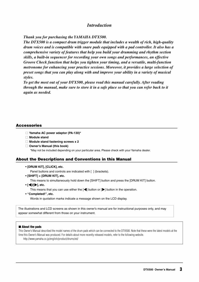
Thank you for purchasing the YAMAHA DTX500.The DTX500 is a compact drum trigger module that includes a wealth of rich, high-quality drum voices and is compatible with snare pads equipped with a pad controller. It also has a comprehensive variety of features that help you build your drumming and rhythm section skills, a built-in sequencer for recording your own songs and performances, an effective Groove Check function that helps you tighten your timing, and a versatile, multi-function metronome for enhancing your practice sessions. Moreover, it provides a large selection of preset songs that you can play along with and improve your ability in a variety of musical styles.To get the most out of your DTX500, please read this manual carefully. After reading through the manual, make sure to store it in a safe place so that you can refer back to it again as needed.
Accessories
Yamaha AC power adaptor (PA-130)*Module stand Module stand fastening screws x 2Owner’s Manual (this book)*May not be included depending on your particular area. Please check with your Yamaha dealer.
About the Descriptions and Conventions in this Manual
• [DRUM KIT], [CLICK], etc.
Panel buttons and controls are indicated with [ ] (brackets).• [SHIFT] + [DRUM KIT], etc.
This means to simultaneously hold down the [SHIFT] button and press the [DRUM KIT] button.• [<<<<]/[>>>>], etc.
This means that you can use either the [<<<<] button or [>>>>] button in the operation.• “Completed!”, etc.
Words in quotation marks indicate a message shown on the LCD display.
The illustrations and LCD screens as shown in this owner’s manual are for instructional purposes only, and may appear somewhat different from those on your instrument.
About the padsThis Owner’s Manual described the model names of the drum pads which can be connected to the DTX500. Note that these were the latest models at the time this Owner’s Manual was produced. For details about more recently released models, refer to the following website.
http://www.yamaha.co.jp/english/product/drums/ed/
3DTX500 Owner’s Manual
PRECAUTIONSPLEASE READ CAREFULLY BEFORE PROCEEDING
* Please keep this manual in a safe place for future reference.
WARNINGAlways follow the basic precautions listed below to avoid the possibility of serious injury or even death from electrical shock, short-circuiting, damages, fire or other hazards. These precautions include, but are not limited to, the following:
• Do not place the power cord near heat sources such as heaters or radiators, and do not excessively bend or otherwise damage the cord, place heavy objects on it, or place it in a position where anyone could walk on, trip over, or roll anything over it.
• Only use the voltage specified as correct for the instrument. The required voltage is printed on the name plate of the instrument.
• Use the specified adaptor (page 3) only. Using the wrong adaptor can result in damage to the instrument or overheating.
• Check the electric plug periodically and remove any dirt or dust which may have accumulated on it.
• This instrument contains no user-serviceable parts. Do not attempt to disassemble or modify the internal components in any way. If it should appear to be malfunctioning, discontinue use immediately and have it inspected by qualified Yamaha service personnel.
• Do not expose the instrument to rain, use it near water or in damp or wet conditions, or place containers on it containing liquids which might spill into any openings. If any liquid such as water seeps into the instrument, turn off the power immediately and unplug the power cord from the AC outlet. Then have the instrument inspected by qualified Yamaha service personnel.
• Never insert or remove an electric plug with wet hands.
• Do not put burning items, such as candles, on the unit. A burning item may fall over and cause a fire.
• When one of the following problems occur, immediately turn off the power switch and disconnect the electric plug from the outlet. Then have the device inspected by Yamaha service personnel.• The power cord or plug becomes frayed or damaged.• It emits unusual smells or smoke.• Some object has been dropped into the instrument.• There is a sudden loss of sound during use of the instrument.
CAUTIONAlways follow the basic precautions listed below to avoid the possibility of physical injury to you or others, or damage to the instrument or other property. These precautions include, but are not limited to, the following:
• Do not connect the instrument to an electrical outlet using a multiple-connector. Doing so can result in lower sound quality, or possibly cause overheating in the outlet.
• When removing the electric plug from the instrument or an outlet, always hold the plug itself and not the cord. Pulling by the cord can damage it.
• Remove the electric plug from the outlet when the instrument is not to be used for extended periods of time, or during electrical storms.
• Do not place the instrument in an unstable position where it might accidentally fall over.
• Before moving the instrument, remove all connected cables.• When setting up the product, make sure that the AC outlet you are
using is easily accessible. If some trouble or malfunction occurs, immediately turn off the power switch and disconnect the plug from the outlet. Even when the power switch is turned off, electricity is still flowing to the product at the minimum level. When you are not using the product for a long time, make sure to unplug the power cord from the wall AC outlet.
• Use only the rack specified for the instrument. When attaching the stand or rack, use the provided screws only. Failure to do so could cause damage to the internal components or result in the instrument falling over.
• Before connecting the instrument to other electronic components, turn off the power for all components. Before turning the power on or off for all components, set all volume levels to minimum.
• Be sure to set the volumes of all components at their minimum levels and gradually raise the volume controls while playing the instrument to set the desired listening level.
• Do not rest your weight on, or place heavy objects on the instrument, and do not use excessive force on the buttons, switches or connectors.
• Do not use the instrument/device or headphones for a long period of time at a high or uncomfortable volume level, since this can cause permanent hearing loss. If you experience any hearing loss or ringing in the ears, consult a physician.
Power supply/AC power adaptor
Do not open
Water warning
Fire warning
If you notice any abnormality
Power supply/AC power adaptor
Location
Connections
Handling caution
4 DTX500 Owner’s Manual
(7)-1 1/2
Yamaha cannot be held responsible for damage caused by improper use or modifications to the instrument, or data that is lost or destroyed.
Always turn the power off when the instrument is not in use.Even when the power switch is in the “STANDBY” position, electricity is still flowing to the instrument at the minimum level. When you are not using the instrument for a long time, make sure you unplug the power cord from the wall AC outlet.
NOTICETo avoid the possibility of damage to the product, data or other property, follow the notices below.
Handling and Maintenance• Do not use the instrument in the vicinity of a TV, radio, stereo equipment, mobile phone, or other electric devices. Otherwise, the
instrument, TV, or radio may generate noise.• Do not expose the instrument to excessive dust or vibrations, or extreme cold or heat (such as in direct sunlight, near a heater, or in a car
during the day) to prevent the possibility of panel disfiguration or damage to the internal components.• Do not place vinyl, plastic or rubber objects on the instrument, since this might discolor the panel or keyboard. Saving data• Never attempt to turn off the power while data is being written to Flash ROM (while a “now storing...” message is shown). Turning the
power off in this state results in loss of all user data and may cause the system to freeze (due to corruption of data in the Flash ROM). This means that this instrument may not be able to start up properly, even when turning the power on next time.
Information About copyrights• Copying of the commercially available musical data including but not limited to MIDI data and/or audio data is strictly prohibited except for
your personal use.• This product incorporates and bundles computer programs and contents in which Yamaha owns copyrights or with respect to which it has
license to use others’ copyrights. Such copyrighted materials include, without limitation, all computer software, style files, MIDI files, WAVE data, musical scores and sound recordings. Any unauthorized use of such programs and contents outside of personal use is not permitted under relevant laws. Any violation of copyright has legal consequences. DON’T MAKE, DISTRIBUTE OR USE ILLEGAL COPIES.
About this manual• The illustrations and LCD screens as shown in this manual are for instructional purposes only, and may appear somewhat different from
those on your instrument.• The company names and product names in this manual are the trademarks or registered trademarks of their respective companies.
(7)-1 2/2
Information for Users on Collection and Disposal of Old EquipmentThis symbol on the products, packaging, and/or accompanying documents means that used electrical and electronic products should not be mixed with general household waste.For proper treatment, recovery and recycling of old products, please take them to applicable collection points, in accordance with your national legislation and the Directives 2002/96/EC.
By disposing of these products correctly, you will help to save valuable resources and prevent any potential negative effects on human health and the environment which could otherwise arise from inappropriate waste handling.
For more information about collection and recycling of old products, please contact your local municipality, your waste disposal service or the point of sale where you purchased the items.
[For business users in the European Union]If you wish to discard electrical and electronic equipment, please contact your dealer or supplier for further information.
[Information on Disposal in other Countries outside the European Union]This symbol is only valid in the European Union. If you wish to discard these items, please contact your local authorities or dealer and ask for the correct method of disposal.
OBSERVERA!Apparaten kopplas inte ur växelströmskällan (nätet) så länge som den ar ansluten till vägguttaget, även om själva apparaten har stängts av.
ADVARSEL: Netspændingen til dette apparat er IKKE afbrudt, sålæenge netledningen siddr i en stikkontakt, som er t endt — også selvom der or slukket på apparatets afbryder.
VAROITUS: Laitteen toisiopiiriin kytketty käyttökytkin ei irroita koko laitetta verkosta.
(standby)
5DTX500 Owner’s Manual
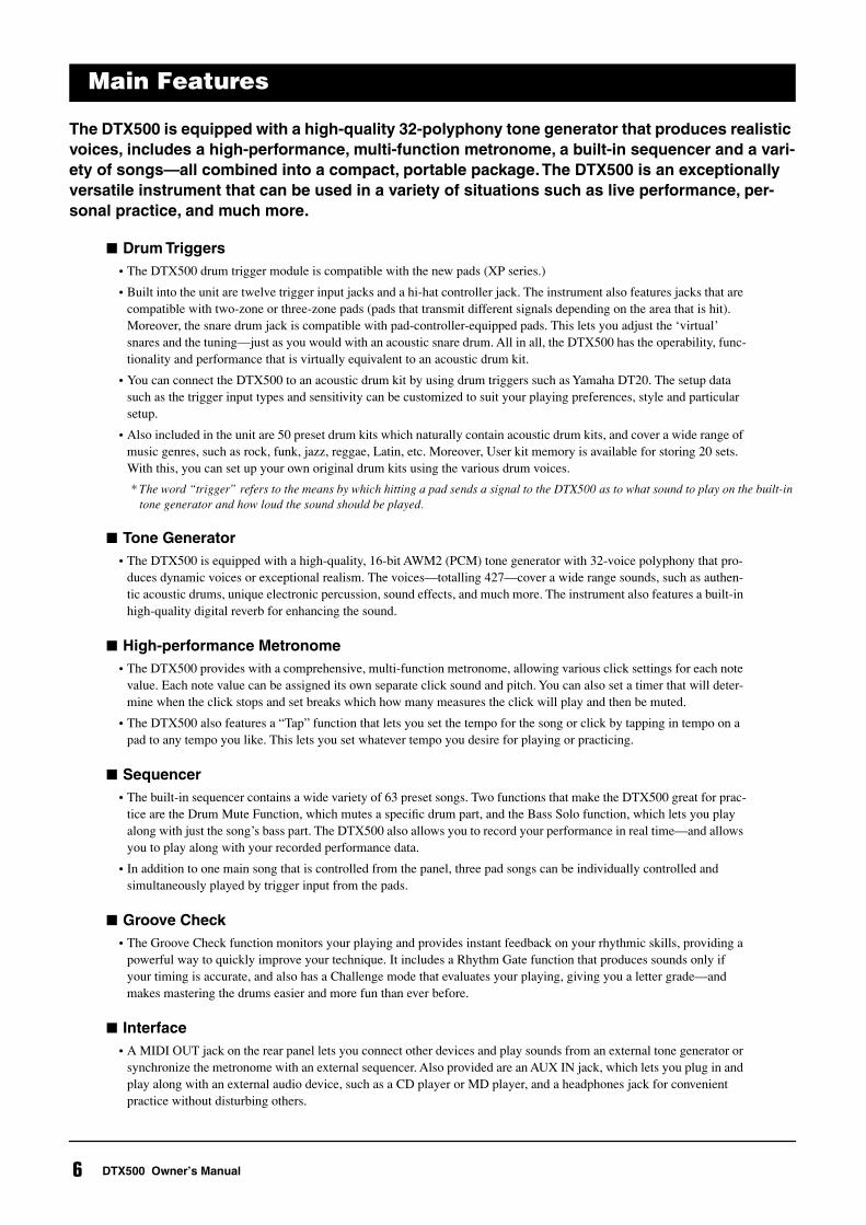
The DTX500 is equipped with a high-quality 32-polyphony tone generator that produces realistic voices, includes a high-performance, multi-function metronome, a built-in sequencer and a vari-ety of songs—all combined into a compact, portable package. The DTX500 is an exceptionally versatile instrument that can be used in a variety of situations such as live performance, per-sonal practice, and much more.
Drum Triggers• The DTX500 drum trigger module is compatible with the new pads (XP series.)
• Built into the unit are twelve trigger input jacks and a hi-hat controller jack. The instrument also features jacks that are compatible with two-zone or three-zone pads (pads that transmit different signals depending on the area that is hit). Moreover, the snare drum jack is compatible with pad-controller-equipped pads. This lets you adjust the ‘virtual’ snares and the tuning—just as you would with an acoustic snare drum. All in all, the DTX500 has the operability, func-tionality and performance that is virtually equivalent to an acoustic drum kit.
• You can connect the DTX500 to an acoustic drum kit by using drum triggers such as Yamaha DT20. The setup data such as the trigger input types and sensitivity can be customized to suit your playing preferences, style and particular setup.
• Also included in the unit are 50 preset drum kits which naturally contain acoustic drum kits, and cover a wide range of music genres, such as rock, funk, jazz, reggae, Latin, etc. Moreover, User kit memory is available for storing 20 sets. With this, you can set up your own original drum kits using the various drum voices.
* The word “trigger” refers to the means by which hitting a pad sends a signal to the DTX500 as to what sound to play on the built-in tone generator and how loud the sound should be played.
Tone Generator• The DTX500 is equipped with a high-quality, 16-bit AWM2 (PCM) tone generator with 32-voice polyphony that pro-
duces dynamic voices or exceptional realism. The voices—totalling 427—cover a wide range sounds, such as authen-tic acoustic drums, unique electronic percussion, sound effects, and much more. The instrument also features a built-in high-quality digital reverb for enhancing the sound.
High-performance Metronome• The DTX500 provides with a comprehensive, multi-function metronome, allowing various click settings for each note
value. Each note value can be assigned its own separate click sound and pitch. You can also set a timer that will deter-mine when the click stops and set breaks which how many measures the click will play and then be muted.
• The DTX500 also features a “Tap” function that lets you set the tempo for the song or click by tapping in tempo on a pad to any tempo you like. This lets you set whatever tempo you desire for playing or practicing.
Sequencer• The built-in sequencer contains a wide variety of 63 preset songs. Two functions that make the DTX500 great for prac-
tice are the Drum Mute Function, which mutes a specific drum part, and the Bass Solo function, which lets you play along with just the song’s bass part. The DTX500 also allows you to record your performance in real time—and allows you to play along with your recorded performance data.
• In addition to one main song that is controlled from the panel, three pad songs can be individually controlled and simultaneously played by trigger input from the pads.
Groove Check• The Groove Check function monitors your playing and provides instant feedback on your rhythmic skills, providing a
powerful way to quickly improve your technique. It includes a Rhythm Gate function that produces sounds only if your timing is accurate, and also has a Challenge mode that evaluates your playing, giving you a letter grade—and makes mastering the drums easier and more fun than ever before.
Interface• A MIDI OUT jack on the rear panel lets you connect other devices and play sounds from an external tone generator or
synchronize the metronome with an external sequencer. Also provided are an AUX IN jack, which lets you plug in and play along with an external audio device, such as a CD player or MD player, and a headphones jack for convenient practice without disturbing others.
Main Features
6 DTX500 Owner’s Manual
7
DTX500 Owner’s Manual
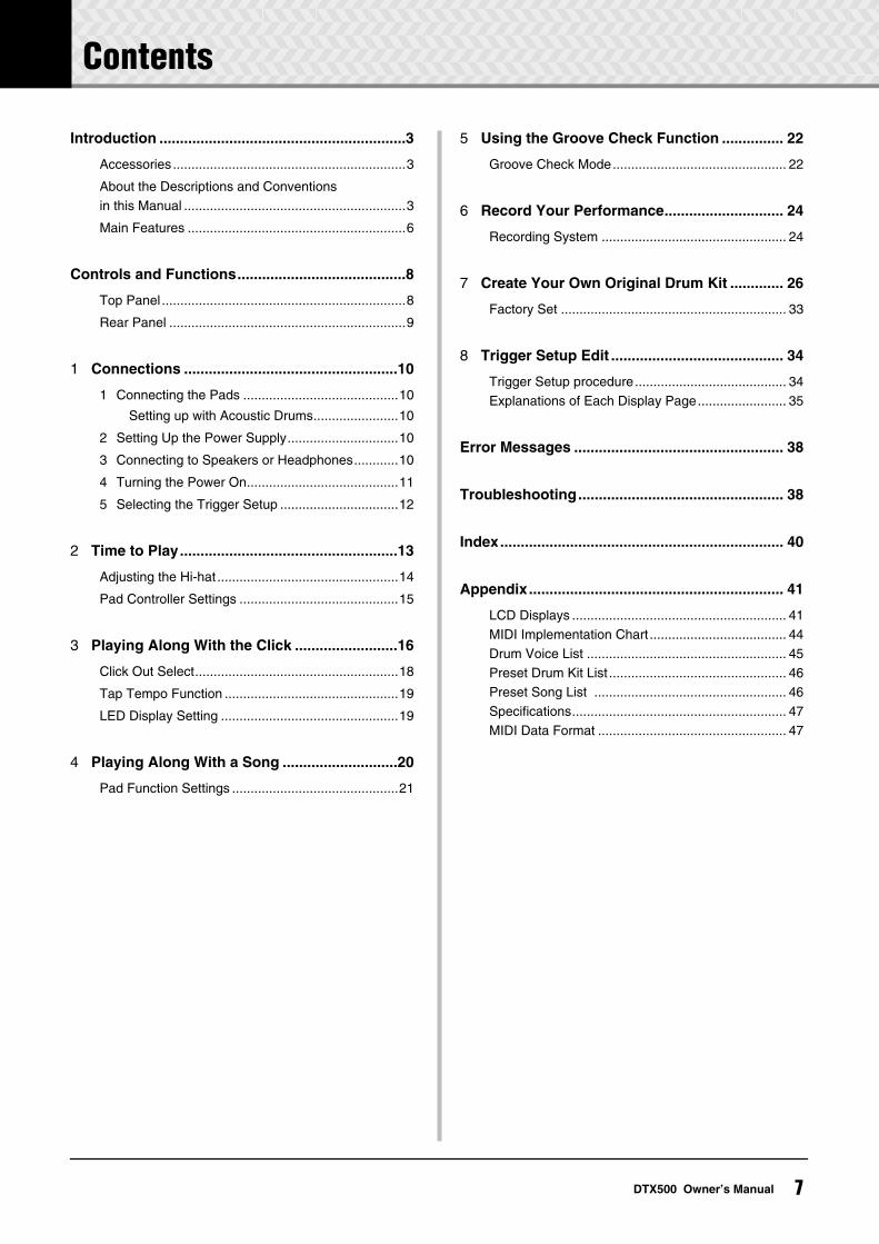
Introduction ............................................................3
Accessories...............................................................3
About the Descriptions and Conventions in this Manual ............................................................3
Main Features ...........................................................6
Controls and Functions.........................................8
Top Panel ..................................................................8
Rear Panel ................................................................9
1
Connections ....................................................10
1 Connecting the Pads ..........................................10
Setting up with Acoustic Drums.......................10
2 Setting Up the Power Supply..............................10
3 Connecting to Speakers or Headphones............10
4 Turning the Power On.........................................11
5 Selecting the Trigger Setup ................................12
2
Time to Play.....................................................13
Adjusting the Hi-hat .................................................14
Pad Controller Settings ...........................................15
3
Playing Along With the Click .........................16
Click Out Select.......................................................18
Tap Tempo Function ...............................................19
LED Display Setting ................................................19
4
Playing Along With a Song ............................20
Pad Function Settings .............................................21
5
Using the Groove Check Function ............... 22
Groove Check Mode............................................... 22
6
Record Your Performance............................. 24
Recording System .................................................. 24
7
Create Your Own Original Drum Kit ............. 26
Factory Set ............................................................. 33
8
Trigger Setup Edit .......................................... 34
Trigger Setup procedure......................................... 34Explanations of Each Display Page........................ 35
Error Messages ................................................... 38
Troubleshooting.................................................. 38
Index..................................................................... 40
Appendix.............................................................. 41
LCD Displays .......................................................... 41MIDI Implementation Chart ..................................... 44Drum Voice List ...................................................... 45Preset Drum Kit List ................................................ 46Preset Song List .................................................... 46Specifications.......................................................... 47MIDI Data Format ................................................... 47
Contents
Controls and Functions
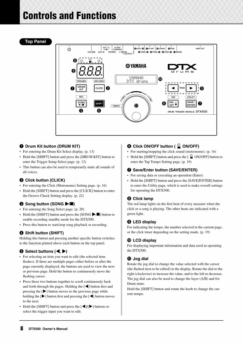
q Drum Kit button (DRUM KIT)• For entering the Drum Kit Select display. (p. 13)
• Hold the [SHIFT] button and press the [DRUM KIT] button to enter the Trigger Setup Select page. (p. 12)
• This button can also be used to temporarily mute all sounds of all voices.
w Click button (CLICK)• For entering the Click (Metronome) Setting page. (p. 16)
• Hold the [SHIFT] button and press the [CLICK] button to enter the Groove Check Setting display. (p. 22)
e Song button (SONG >>>>/)• For entering the Song Select page. (p. 20)
• Hold the [SHIFT] button and press the [SONG >>>>/] button to enable recording standby mode for the DTX500.
• Press this button to start/stop song playback or recording.
r Shift button (SHIFT)Holding this button and pressing another specific button switches to the function printed above each button on the top panel.
t Select buttons (<<<<, >>>>)• For selecting an item you want to edit (the selected item
flashes). If there are multiple pages either before or after the page currently displayed, the buttons are used to view the next or previous page. Hold the button to continuously move the flashing cursor.
• Press these two buttons together to scroll continuously back and forth through the pages. Holding the [<] button first and pressing the [>] button moves to the previous page while holding the [>] button first and pressing the [<] button moves to the next.
• Hold the [SHIFT] button and press the [<]/[>] buttons to select the trigger input you want to edit.
y Click ON/OFF button ( ON/OFF)• For starting/stopping the click sound (metronome). (p. 16)
• Hold the [SHIFT] button and press the [ ON/OFF] button to enter the Tap Tempo Setting page. (p. 19)
u Save/Enter button (SAVE/ENTER)• For saving data or executing an operation (Enter).
• Hold the [SHIFT] button and press the [SAVE/ENTER] button to enter the Utility page, which is used to make overall settings for operating the DTX500.
i Click lampThe red lamp lights on the first beat of every measure when the click or a song is playing. The other beats are indicated with a green light.
o LED displayFor indicating the tempo, the number selected in the current page, or the click timer depending on the setting made. (p. 19)
!0 LCD displayFor displaying important information and data used in operating the DTX500.
!1 Jog dialRotate the jog dial to change the value selected with the cursor (the flashed item to be edited) in the display. Rotate the dial to the right (clockwise) to increase the value, and to the left to decrease. The jog dial can also be used to change the layer (A/B) and for Drum mute.
Hold the [SHIFT] button and rotate the knob to change the cur-rent tempo.
q
o
i
w
e r
u
t
y
!0
!1
~~~~~YAMAHA ~~~~~~~ DTX drums~~
8.8.8.
Top Panel
8 DTX500 Owner’s Manual
Controls and Functions
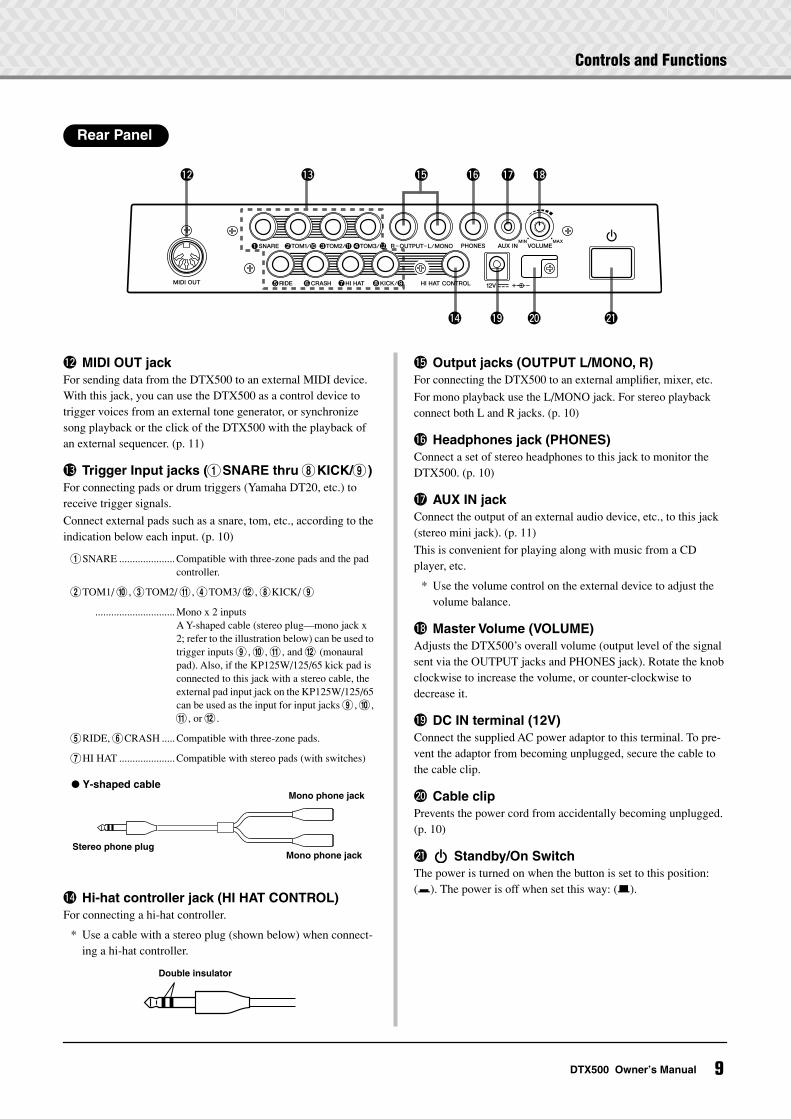
!2 MIDI OUT jackFor sending data from the DTX500 to an external MIDI device. With this jack, you can use the DTX500 as a control device to trigger voices from an external tone generator, or synchronize song playback or the click of the DTX500 with the playback of an external sequencer. (p. 11)
!3 Trigger Input jacks (1SNARE thru 8KICK/9)For connecting pads or drum triggers (Yamaha DT20, etc.) to receive trigger signals.
Connect external pads such as a snare, tom, etc., according to the indication below each input. (p. 10)
1SNARE .....................Compatible with three-zone pads and the pad controller.
2TOM1/ 0, 3TOM2/ !, 4TOM3/ @, 8KICK/ 9
..............................Mono x 2 inputsA Y-shaped cable (stereo plug—mono jack x 2; refer to the illustration below) can be used to trigger inputs 9, 0, !, and @ (monaural pad). Also, if the KP125W/125/65 kick pad is connected to this jack with a stereo cable, the external pad input jack on the KP125W/125/65 can be used as the input for input jacks 9, 0, !, or @.
5RIDE, 6CRASH .....Compatible with three-zone pads.
7HI HAT .....................Compatible with stereo pads (with switches)
!4 Hi-hat controller jack (HI HAT CONTROL)For connecting a hi-hat controller.
* Use a cable with a stereo plug (shown below) when connect-ing a hi-hat controller.
!5 Output jacks (OUTPUT L/MONO, R)For connecting the DTX500 to an external amplifier, mixer, etc.
For mono playback use the L/MONO jack. For stereo playback connect both L and R jacks. (p. 10)
!6 Headphones jack (PHONES)Connect a set of stereo headphones to this jack to monitor the DTX500. (p. 10)
!7 AUX IN jackConnect the output of an external audio device, etc., to this jack (stereo mini jack). (p. 11)
This is convenient for playing along with music from a CD player, etc.
* Use the volume control on the external device to adjust the volume balance.
!8 Master Volume (VOLUME)Adjusts the DTX500’s overall volume (output level of the signal sent via the OUTPUT jacks and PHONES jack). Rotate the knob clockwise to increase the volume, or counter-clockwise to decrease it.
!9 DC IN terminal (12V)Connect the supplied AC power adaptor to this terminal. To pre-vent the adaptor from becoming unplugged, secure the cable to the cable clip.
@0 Cable clipPrevents the power cord from accidentally becoming unplugged. (p. 10)
@1 Standby/On SwitchThe power is turned on when the button is set to this position: (>). The power is off when set this way: (?).
!2 !3 !6 !7 !8!5
!4 !9 @0 @1
Rear Panel
Stereo phone plug
Mono phone jack
Mono phone jack
Y-shaped cable
Double insulator
9DTX500 Owner’s Manual
1 Connections
In this chapter, you’ll learn how to set up the DTX500. Read these instructions carefully and in the following order to ensure that the instrument sounds and operates properly: 1 Connecting the Pads → 2 Setting Up the Power Supply (p. 10) → 3 Connecting to Speakers or Head-phones (p. 10) → 4 Turning the Power On (p. 11) → 5 Selecting the Trigger Setup (p. 12)
1 Connecting the Pads
Referring to the illustration below, connect the output cable from each pad to each Trigger Input jack located on the rear panel of the DTX500. For details, see the Assembly Manual that comes with the drum set you are using.
The DTX500 can be played from an acoustic drum kit if the kit is fitted with an optional set of drum triggers (such as Yamaha DT20 Drum Triggers) and the triggers are properly connected to the input jacks of the DTX500.
2 Setting Up the Power Supply
A special power source adaptor supplies power to the DTX500.
2-1. Make sure that the Standby/On Switch of the DTX500 is set to the standby (?) position.
2-2. Connect the DC plug of the included AC power adaptor to
the DC IN terminal on the rear panel.
To prevent the cord from being unplugged accidentally,
wrap the cord around the cable clip and secure it.
2-3. Connect the other end of the power cord to an AC outlet.
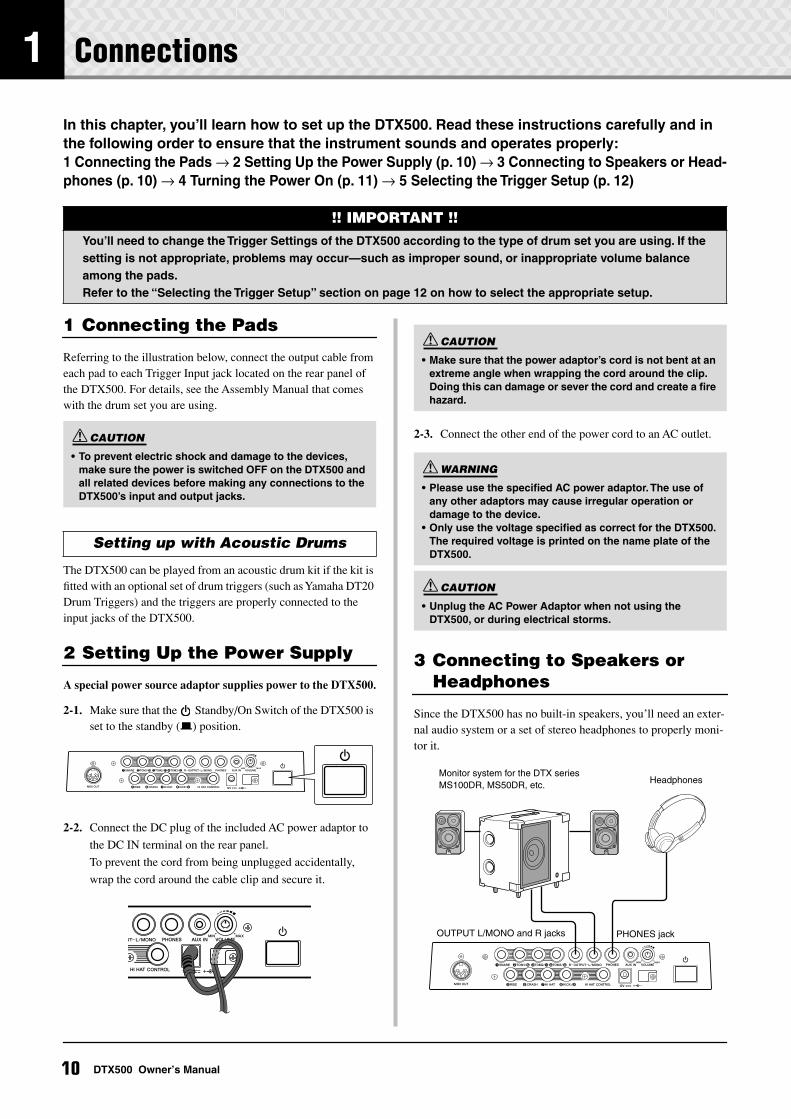
3 Connecting to Speakers or Headphones
Since the DTX500 has no built-in speakers, you’ll need an exter-nal audio system or a set of stereo headphones to properly moni-tor it.
!! IMPORTANT !!You’ll need to change the Trigger Settings of the DTX500 according to the type of drum set you are using. If the setting is not appropriate, problems may occur—such as improper sound, or inappropriate volume balance among the pads.Refer to the “Selecting the Trigger Setup” section on page 12 on how to select the appropriate setup.
• To prevent electric shock and damage to the devices, make sure the power is switched OFF on the DTX500 and all related devices before making any connections to the DTX500’s input and output jacks.
Setting up with Acoustic Drums
CAUTION
• Make sure that the power adaptor’s cord is not bent at an extreme angle when wrapping the cord around the clip. Doing this can damage or sever the cord and create a fire hazard.
• Please use the specified AC power adaptor. The use of any other adaptors may cause irregular operation or damage to the device.
• Only use the voltage specified as correct for the DTX500. The required voltage is printed on the name plate of the DTX500.
• Unplug the AC Power Adaptor when not using the DTX500, or during electrical storms.
CAUTION
WARNING
CAUTION
HeadphonesMonitor system for the DTX seriesMS100DR, MS50DR, etc.
OUTPUT L/MONO and R jacks PHONES jack
10 DTX500 Owner’s Manual
1 Connections
OUTPUT L/MONO, R jacks (standard mono phone)
These jacks allow you to connect the DTX500 to an external amplifier + speak-ers and produce full, amplified sound, or connect the DTX500 to audio recording equipment for recording your own perfor-mance.
* Use the DTX500’s OUTPUT L/MONO jack when connect-ing to a device with a mono input.
PHONES jack (standard stereo phone jack)
Use the VOLUME knob on the rear panel to adjust the headphone volume.
AUX IN jack (stereo mini phone jack)
The audio output from a MP3 player or CD player connected to the AUX IN jack can be mixed with the sound of the DTX500 and transmitted via the OUT-PUT jacks or PHONES jack. This jack can be used when you want to play along with your favorite songs.
* Use the volume control on the external device (MP3 player, etc.) to adjust the volume balance.
MIDI OUT jack
The MIDI functions on the DTX500 lets you play voices on an external tone generator with the pads of the DTX500, or synchro-nize the DTX500’s song or click playback with the playback of an external sequencer.
About MIDIMIDI (Musical Instrument Digital Inter-face) is a worldwide standard that enables you to connect instruments and comput-ers—of different manufacturers and differ-ent types—and transmit performance and other data among them.
* Also, use a MIDI cable that is not more than 15 meters in length. Using a longer cable may result in irregular operation and other problems.
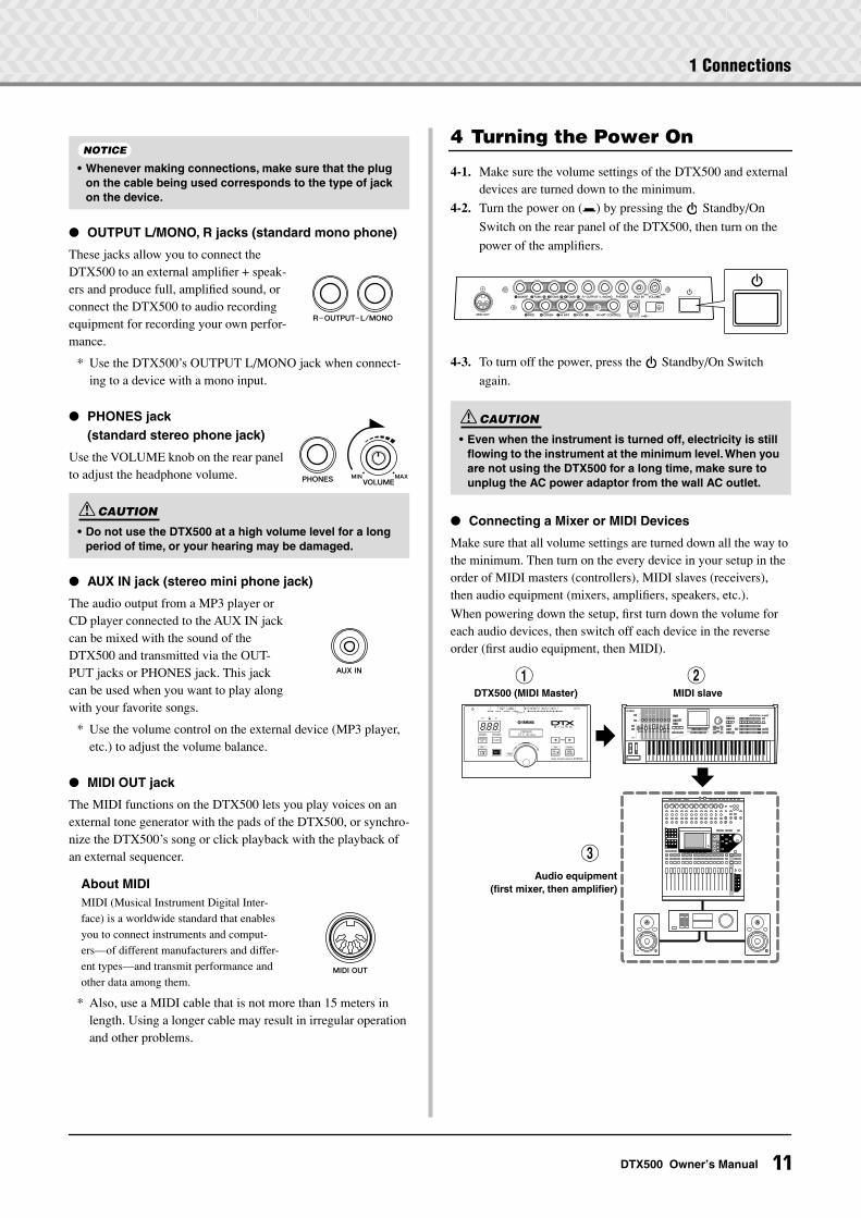
4 Turning the Power On
4-1. Make sure the volume settings of the DTX500 and external devices are turned down to the minimum.
4-2. Turn the power on (>) by pressing the Standby/On
Switch on the rear panel of the DTX500, then turn on the
power of the amplifiers.
4-3. To turn off the power, press the Standby/On Switch
again.
Connecting a Mixer or MIDI Devices
Make sure that all volume settings are turned down all the way to the minimum. Then turn on the every device in your setup in the order of MIDI masters (controllers), MIDI slaves (receivers), then audio equipment (mixers, amplifiers, speakers, etc.).
When powering down the setup, first turn down the volume for each audio devices, then switch off each device in the reverse order (first audio equipment, then MIDI).
• Whenever making connections, make sure that the plug on the cable being used corresponds to the type of jack on the device.
• Do not use the DTX500 at a high volume level for a long period of time, or your hearing may be damaged.
NOTICE
CAUTION
• Even when the instrument is turned off, electricity is still flowing to the instrument at the minimum level. When you are not using the DTX500 for a long time, make sure to unplug the AC power adaptor from the wall AC outlet.
CAUTION
~~~~~YAMAHA ~~~~~~~ DTX drums~~
8.8.8.
3Audio equipment
(first mixer, then amplifier)
1DTX500 (MIDI Master)
2MIDI slave
11DTX500 Owner’s Manual
1 Connections
5 Selecting the Trigger Setup
This setting lets you select the Trigger Setup that most closely matches the trigger output levels and functions of your pads.
Use the operation described below to select the Trigger Setup you want to use.
Procedure
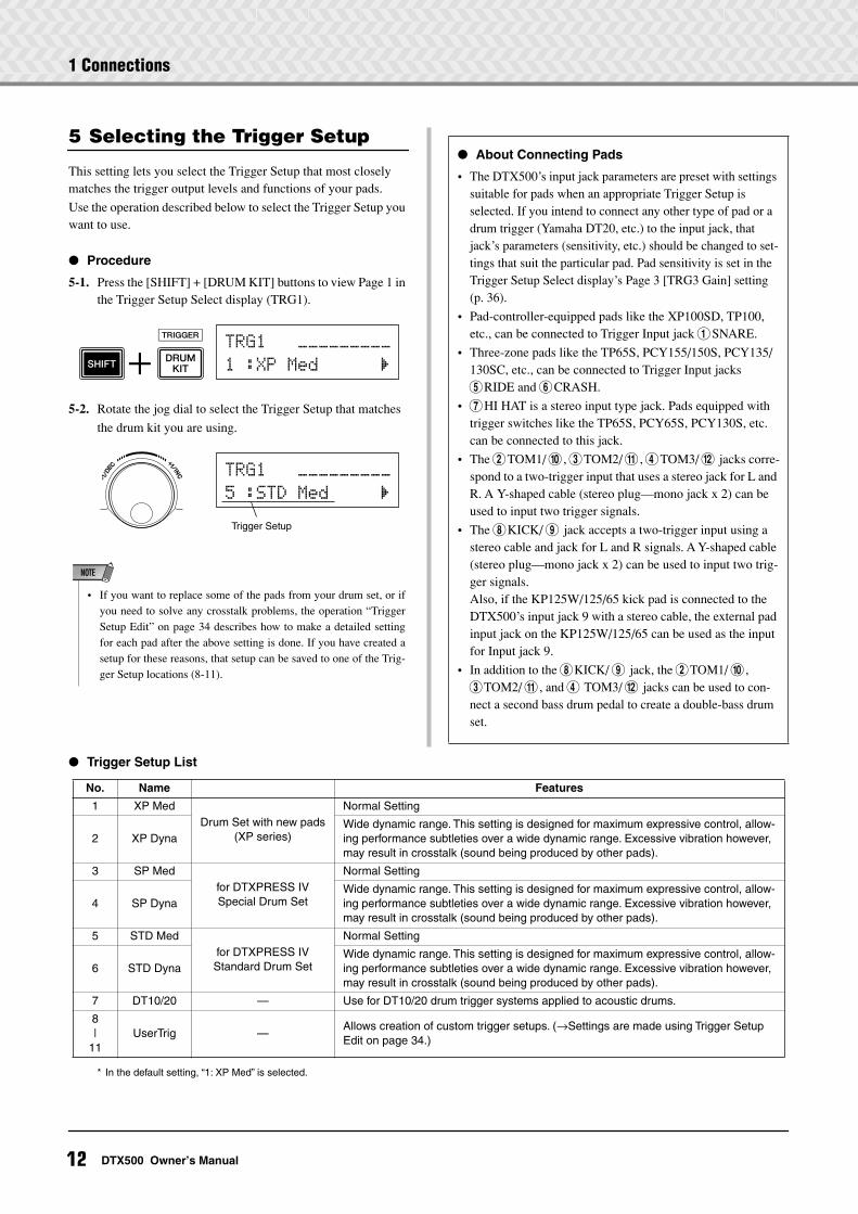
5-1. Press the [SHIFT] + [DRUM KIT] buttons to view Page 1 in the Trigger Setup Select display (TRG1).
5-2. Rotate the jog dial to select the Trigger Setup that matches
the drum kit you are using.
Trigger Setup List
TRG1~~~ååååååååå
1~:XP~Med~~~~~~‚
Trigger Setup
TRG1~~~ååååååååå
5~:STD~Med~~~~~‚
• If you want to replace some of the pads from your drum set, or ifyou need to solve any crosstalk problems, the operation “TriggerSetup Edit” on page 34 describes how to make a detailed settingfor each pad after the above setting is done. If you have created asetup for these reasons, that setup can be saved to one of the Trig-ger Setup locations (8-11).
NOTE
About Connecting Pads
• The DTX500’s input jack parameters are preset with settings suitable for pads when an appropriate Trigger Setup is selected. If you intend to connect any other type of pad or a drum trigger (Yamaha DT20, etc.) to the input jack, that jack’s parameters (sensitivity, etc.) should be changed to set-tings that suit the particular pad. Pad sensitivity is set in the Trigger Setup Select display’s Page 3 [TRG3 Gain] setting (p. 36).
• Pad-controller-equipped pads like the XP100SD, TP100, etc., can be connected to Trigger Input jack 1SNARE.
• Three-zone pads like the TP65S, PCY155/150S, PCY135/130SC, etc., can be connected to Trigger Input jacks 5RIDE and 6CRASH.
• 7HI HAT is a stereo input type jack. Pads equipped with trigger switches like the TP65S, PCY65S, PCY130S, etc. can be connected to this jack.
• The 2TOM1/ 0, 3TOM2/ !, 4TOM3/ @ jacks corre-spond to a two-trigger input that uses a stereo jack for L and R. A Y-shaped cable (stereo plug—mono jack x 2) can be used to input two trigger signals.
• The 8KICK/ 9 jack accepts a two-trigger input using a stereo cable and jack for L and R signals. A Y-shaped cable (stereo plug—mono jack x 2) can be used to input two trig-ger signals.Also, if the KP125W/125/65 kick pad is connected to the DTX500’s input jack 9 with a stereo cable, the external pad input jack on the KP125W/125/65 can be used as the input for Input jack 9.
• In addition to the 8KICK/ 9 jack, the 2TOM1/ 0, 3TOM2/ !, and 4 TOM3/ @ jacks can be used to con-nect a second bass drum pedal to create a double-bass drum set.
* In the default setting, “1: XP Med” is selected.
No. Name Features
1 XP MedDrum Set with new pads
(XP series)
Normal Setting
2 XP DynaWide dynamic range. This setting is designed for maximum expressive control, allow-ing performance subtleties over a wide dynamic range. Excessive vibration however, may result in crosstalk (sound being produced by other pads).
3 SP Medfor DTXPRESS IVSpecial Drum Set
Normal Setting
4 SP DynaWide dynamic range. This setting is designed for maximum expressive control, allow-ing performance subtleties over a wide dynamic range. Excessive vibration however, may result in crosstalk (sound being produced by other pads).
5 STD Medfor DTXPRESS IVStandard Drum Set
Normal Setting
6 STD DynaWide dynamic range. This setting is designed for maximum expressive control, allow-ing performance subtleties over a wide dynamic range. Excessive vibration however, may result in crosstalk (sound being produced by other pads).
7 DT10/20 — Use for DT10/20 drum trigger systems applied to acoustic drums.
8|
11UserTrig —
Allows creation of custom trigger setups. (→Settings are made using Trigger Setup Edit on page 34.)
12 DTX500 Owner’s Manual
2 Time to Play
Now that your DTX500 is properly connected, it’s time to make some music!
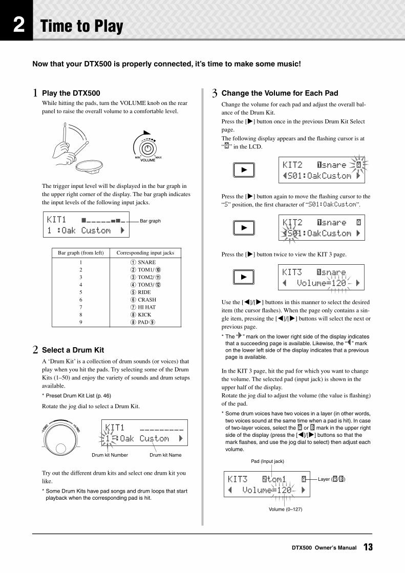
1 Play the DTX500While hitting the pads, turn the VOLUME knob on the rear panel to raise the overall volume to a comfortable level.
The trigger input level will be displayed in the bar graph in the upper right corner of the display. The bar graph indicates the input levels of the following input jacks.
2 Select a Drum KitA ‘Drum Kit’ is a collection of drum sounds (or voices) that play when you hit the pads. Try selecting some of the Drum Kits (1–50) and enjoy the variety of sounds and drum setups available.
* Preset Drum Kit List (p. 46)
Rotate the jog dial to select a Drum Kit.
Try out the different drum kits and select one drum kit you like.
* Some Drum Kits have pad songs and drum loops that start playback when the corresponding pad is hit.
3 Change the Volume for Each PadChange the volume for each pad and adjust the overall bal-ance of the Drum Kit.
Press the [>] button once in the previous Drum Kit Select page.
The following display appears and the flashing cursor is at “˙” in the LCD.
Press the [>] button again to move the flashing cursor to the “S” position, the first character of “S01:OakCustom”.
Press the [>] button twice to view the KIT 3 page.
Use the [<]/[>] buttons in this manner to select the desired item (the cursor flashes). When the page only contains a sin-gle item, pressing the [<]/[>] buttons will select the next or previous page.
* The “‚” mark on the lower right side of the display indicates that a succeeding page is available. Likewise, the “”” mark on the lower left side of the display indicates that a previous page is available.
In the KIT 3 page, hit the pad for which you want to change the volume. The selected pad (input jack) is shown in the upper half of the display.Rotate the jog dial to adjust the volume (the value is flashing) of the pad.
* Some drum voices have two voices in a layer (in other words, two voices sound at the same time when a pad is hit). In case of two-layer voices, select the ˙ or ¶ mark in the upper right side of the display (press the [<]/[>] buttons so that the mark flashes, and use the jog dial to select) then adjust each volume.
Bar graph (from left) Corresponding input jacks
123456789
1 SNARE2 TOM1/ 03 TOM2/ !4 TOM3/ @5 RIDE6 CRASH7 HI HAT8 KICK8 PAD 9
Bar graphKIT1~~~∑åååååø¥å
1~:Oak~Custom~~‚
KIT1~~~ååååååååå
1~:Oak~Custom~~‚
Drum kit Number Drum kit Name
KIT2~~~ƒsnare~~˙
”S01:OakCustom~‚
KIT2~~~ƒsnare~~˙
”S01:OakCustom~‚
KIT3~~~ƒsnare~~
”~~Volume=120~~‚
KIT3~~~™tom1~~~˙
”~~Volume=120~~‚
Volume (0–127)
Pad (Input jack)
Layer (˙/¶)
13DTX500 Owner’s Manual
2 Time to Play
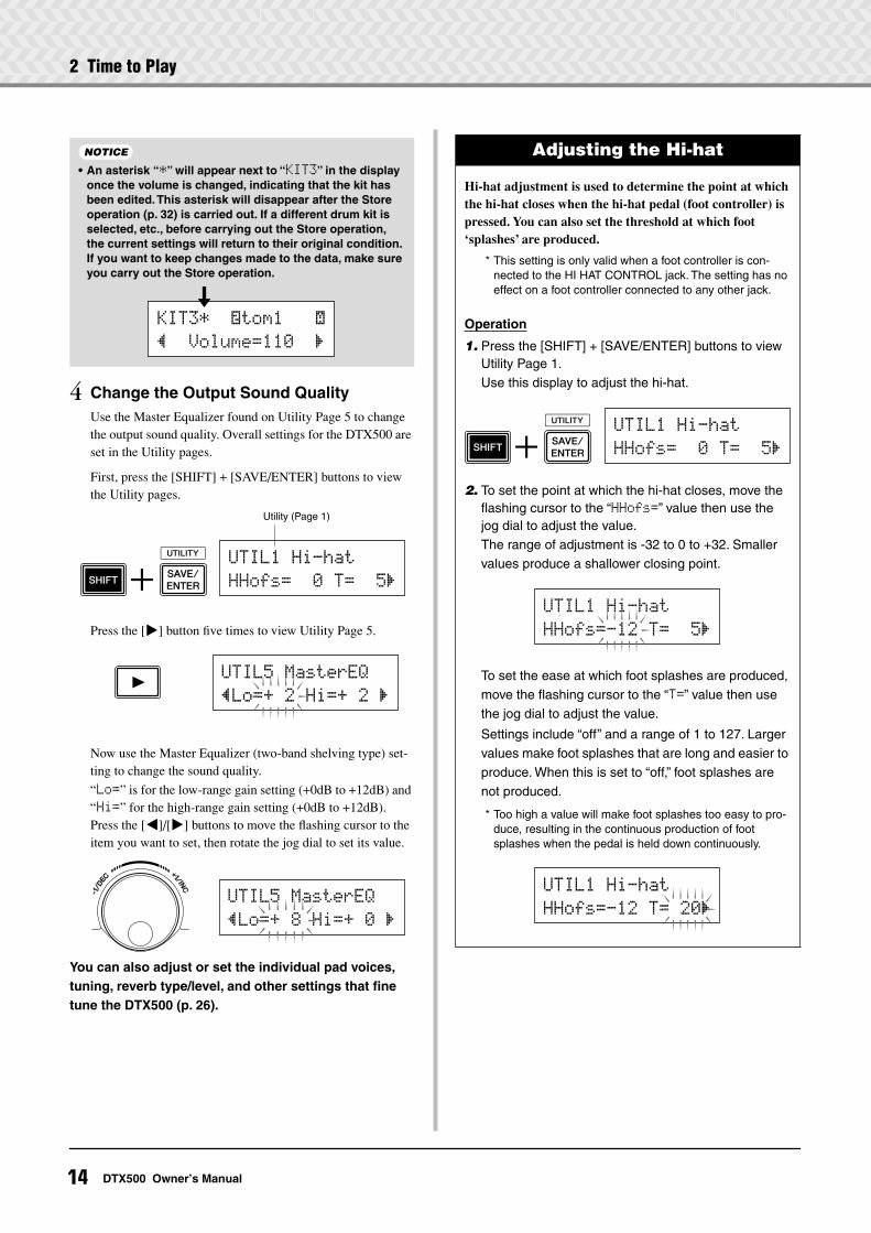
4 Change the Output Sound QualityUse the Master Equalizer found on Utility Page 5 to change the output sound quality. Overall settings for the DTX500 are set in the Utility pages.
First, press the [SHIFT] + [SAVE/ENTER] buttons to view the Utility pages.
Press the [>] button five times to view Utility Page 5.
Now use the Master Equalizer (two-band shelving type) set-ting to change the sound quality.
“Lo=” is for the low-range gain setting (+0dB to +12dB) and “Hi=” for the high-range gain setting (+0dB to +12dB). Press the [<]/[>] buttons to move the flashing cursor to the item you want to set, then rotate the jog dial to set its value.
You can also adjust or set the individual pad voices, tuning, reverb type/level, and other settings that fine tune the DTX500 (p. 26).
• An asterisk “*” will appear next to “KIT3” in the display once the volume is changed, indicating that the kit has been edited. This asterisk will disappear after the Store operation (p. 32) is carried out. If a different drum kit is selected, etc., before carrying out the Store operation, the current settings will return to their original condition. If you want to keep changes made to the data, make sure you carry out the Store operation.
NOTICE
KIT3*~~™tom1~~~˙
”~~Volume=110~~‚
Utility (Page 1)
UTIL1~Hi-hat
HHofs=~~0~T=~~5‚
UTIL5~MasterEQ
”Lo=+~2~Hi=+~2~‚
UTIL5~MasterEQ
”Lo=+~8~Hi=+~0~‚
Adjusting the Hi-hat
Hi-hat adjustment is used to determine the point at which the hi-hat closes when the hi-hat pedal (foot controller) is pressed. You can also set the threshold at which foot ‘splashes’ are produced.
* This setting is only valid when a foot controller is con-nected to the HI HAT CONTROL jack. The setting has no effect on a foot controller connected to any other jack.
Operation
1. Press the [SHIFT] + [SAVE/ENTER] buttons to view Utility Page 1.Use this display to adjust the hi-hat.
2. To set the point at which the hi-hat closes, move the flashing cursor to the “HHofs=” value then use the jog dial to adjust the value.The range of adjustment is -32 to 0 to +32. Smaller values produce a shallower closing point.
To set the ease at which foot splashes are produced, move the flashing cursor to the “T=” value then use the jog dial to adjust the value.
Settings include “off” and a range of 1 to 127. Larger values make foot splashes that are long and easier to produce. When this is set to “off,” foot splashes are not produced.
* Too high a value will make foot splashes too easy to pro-duce, resulting in the continuous production of foot splashes when the pedal is held down continuously.
UTIL1~Hi-hat
HHofs=~~0~T=~~5‚
UTIL1~Hi-hat
HHofs=-12~T=~~5‚
UTIL1~Hi-hat
HHofs=-12~T=~20‚
14 DTX500 Owner’s Manual
2 Time to Play
Pad Controller Settings
When a pad-controller-equipped pad (XP100SD, etc.) is connected, you can adjust the snares setting and tightness, tuning, or tempo by rotating the pad controller knob of the pad.
Operation
In the default setting, you can adjust the snares setting and tightness using the pad controller of the XP100SD (the snare drum pad). To use functions other than the snares adjustment, change the setting as follows.
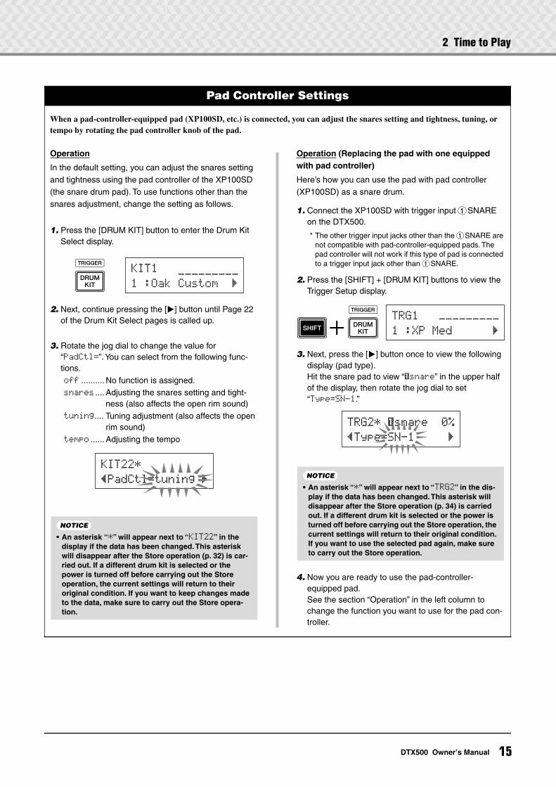
1. Press the [DRUM KIT] button to enter the Drum Kit Select display.
2. Next, continue pressing the [>] button until Page 22 of the Drum Kit Select pages is called up.
3. Rotate the jog dial to change the value for “PadCtl=”. You can select from the following func-tions.
off ..........No function is assigned.snares ....Adjusting the snares setting and tight-
ness (also affects the open rim sound)tuning.... Tuning adjustment (also affects the open
rim sound)tempo ......Adjusting the tempo
Operation (Replacing the pad with one equipped with pad controller)
Here’s how you can use the pad with pad controller (XP100SD) as a snare drum.
1. Connect the XP100SD with trigger input 1SNARE on the DTX500.
* The other trigger input jacks other than the 1SNARE are not compatible with pad-controller-equipped pads. The pad controller will not work if this type of pad is connected to a trigger input jack other than 1SNARE.
2. Press the [SHIFT] + [DRUM KIT] buttons to view the Trigger Setup display.
3. Next, press the [>] button once to view the following display (pad type).Hit the snare pad to view “ƒsnare” in the upper half of the display, then rotate the jog dial to set “Type=SN-1.”
4. Now you are ready to use the pad-controller-equipped pad.See the section “Operation” in the left column to change the function you want to use for the pad con-troller.
KIT1~~~_________
1~:Oak~Custom~~‚
KIT22*
”PadCtl=tuning~‚
• An asterisk “*” will appear next to “KIT22” in the display if the data has been changed. This asterisk will disappear after the Store operation (p. 32) is car-ried out. If a different drum kit is selected or the power is turned off before carrying out the Store operation, the current settings will return to their original condition. If you want to keep changes made to the data, make sure to carry out the Store opera-tion.
NOTICE
TRG1~~~ååååååååå
1~:XP Med~~~~~~‚
TRG2*~ƒsnare~~0%
”Type=SN-1~~~~~‚
• An asterisk “*” will appear next to “TRG2” in the dis-play if the data has been changed. This asterisk will disappear after the Store operation (p. 34) is carried out. If a different drum kit is selected or the power is turned off before carrying out the Store operation, the current settings will return to their original condition. If you want to use the selected pad again, make sure to carry out the Store operation.
NOTICE
15DTX500 Owner’s Manual
3 Playing Along With the Click
Play the DTX500 along with the click (metronome).The DTX500 is equipped with a high-performance metronome that gives you a comprehensive variety of settings and allows you to create complex rhythms.
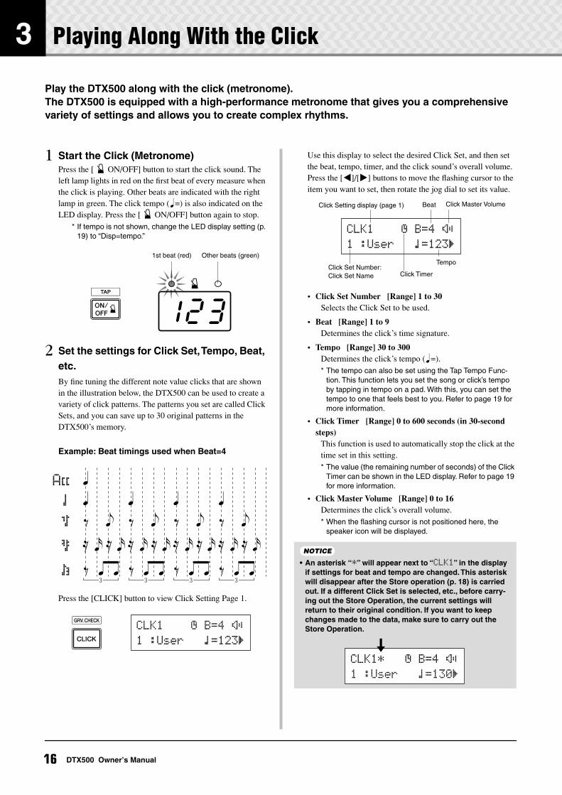
1 Start the Click (Metronome)Press the [ ON/OFF] button to start the click sound. The left lamp lights in red on the first beat of every measure when the click is playing. Other beats are indicated with the right lamp in green. The click tempo (q=) is also indicated on the LED display. Press the [ ON/OFF] button again to stop.
* If tempo is not shown, change the LED display setting (p. 19) to “Disp=tempo.”
2 Set the settings for Click Set, Tempo, Beat, etc.By fine tuning the different note value clicks that are shown in the illustration below, the DTX500 can be used to create a variety of click patterns. The patterns you set are called Click Sets, and you can save up to 30 original patterns in the DTX500’s memory.
Example: Beat timings used when Beat=4
Press the [CLICK] button to view Click Setting Page 1.
Use this display to select the desired Click Set, and then set the beat, tempo, timer, and the click sound’s overall volume. Press the [<]/[>] buttons to move the flashing cursor to the item you want to set, then rotate the jog dial to set its value.
• Click Set Number [Range] 1 to 30Selects the Click Set to be used.
• Beat [Range] 1 to 9Determines the click’s time signature.
• Tempo [Range] 30 to 300Determines the click’s tempo (q=).* The tempo can also be set using the Tap Tempo Func-
tion. This function lets you set the song or click’s tempo by tapping in tempo on a pad. With this, you can set the tempo to one that feels best to you. Refer to page 19 for more information.
• Click Timer [Range] 0 to 600 seconds (in 30-second steps)
This function is used to automatically stop the click at the time set in this setting.* The value (the remaining number of seconds) of the Click
Timer can be shown in the LED display. Refer to page 19 for more information.
• Click Master Volume [Range] 0 to 16Determines the click’s overall volume.* When the flashing cursor is not positioned here, the
speaker icon will be displayed.
123
1st beat (red) Other beats (green)
CLK1~~~~∫~B=4~÷ç
1~:User~~~⁄=123‚
• An asterisk “*” will appear next to “CLK1” in the display if settings for beat and tempo are changed. This asterisk will disappear after the Store operation (p. 18) is carried out. If a different Click Set is selected, etc., before carry-ing out the Store Operation, the current settings will return to their original condition. If you want to keep changes made to the data, make sure to carry out the Store Operation.
Tempo
Click Setting display (page 1)
Click Timer
Click Master Volume
Click Set Number: Click Set Name
Beat
CLK1~~~~∫~B=4~÷ç
1~:User~~~⁄=123‚
NOTICE
CLK1*~~~∫~B=4~÷ç
1~:User~~~⁄=130‚
16 DTX500 Owner’s Manual
3 Playing Along With the Click
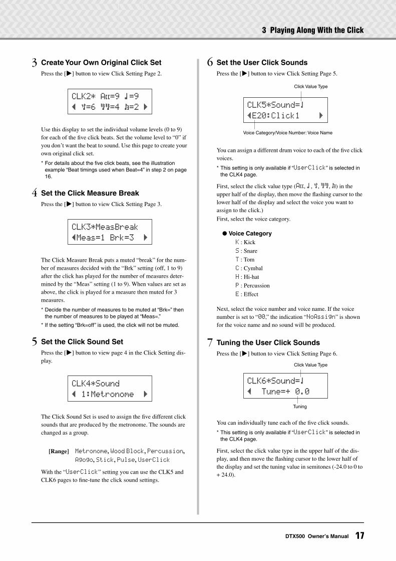
3 Create Your Own Original Click SetPress the [>] button to view Click Setting Page 2.
Use this display to set the individual volume levels (0 to 9) for each of the five click beats. Set the volume level to “0” if you don’t want the beat to sound. Use this page to create your own original click set.
* For details about the five click beats, see the illustration example “Beat timings used when Beat=4” in step 2 on page 16.
4 Set the Click Measure BreakPress the [>] button to view Click Setting Page 3.
The Click Measure Break puts a muted “break” for the num-ber of measures decided with the “Brk” setting (off, 1 to 9) after the click has played for the number of measures deter-mined by the “Meas” setting (1 to 9). When values are set as above, the click is played for a measure then muted for 3 measures.
* Decide the number of measures to be muted at “Brk=” then the number of measures to be played at “Meas=.”
* If the setting “Brk=off” is used, the click will not be muted.
5 Set the Click Sound SetPress the [>] button to view page 4 in the Click Setting dis-play.
The Click Sound Set is used to assign the five different click sounds that are produced by the metronome. The sounds are changed as a group.
[Range] Metronome, Wood Block, Percussion,
Agogo, Stick, Pulse, UserClick
With the “UserClick” setting you can use the CLK5 and CLK6 pages to fine-tune the click sound settings.
6 Set the User Click SoundsPress the [>] button to view Click Setting Page 5.
You can assign a different drum voice to each of the five click voices.
* This setting is only available if “UserClick” is selected in the CLK4 page.
First, select the click value type (A˘, ⁄, ‹, ßß, Œ) in the upper half of the display, then move the flashing cursor to the lower half of the display and select the voice you want to assign to the click.)
First, select the voice category.
Voice CategoryK : Kick
S : Snare
T : Tom
C : Cymbal
H : Hi-hat
P : Percussion
E : Effect
Next, select the voice number and voice name. If the voice number is set to “00,” the indication “NoAssign” is shown for the voice name and no sound will be produced.
7 Tuning the User Click SoundsPress the [>] button to view Click Setting Page 6.
You can individually tune each of the five click sounds.
* This setting is only available if “UserClick” is selected in the CLK4 page.
First, select the click value type in the upper half of the dis-play, and then move the flashing cursor to the lower half of the display and set the tuning value in semitones (-24.0 to 0 to + 24.0).
CLK2*~A˘=9~⁄=9
”~‹=6~ßß=4~Œ=2~‚
CLK3*MeasBreak
”Meas=1~Brk=3~~‚
CLK4*Sound
”~1:Metronome~~‚
Voice Category/Voice Number: Voice Name
CLK5*Sound=¤
”E20:Click1~~~~‚
Click Value Type
Click Value Type
Tuning
CLK6*Sound=¤
”~~Tune=+~0.0
17DTX500 Owner’s Manual
3 Playing Along With the Click
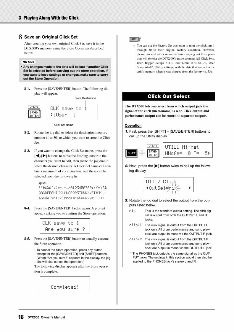
8 Save an Original Click SetAfter creating your own original Click Set, save it in the DTX500’s memory using the Store Operation described below.
8-1. Press the [SAVE/ENTER] button. The following dis-play will appear.
8-2. Rotate the jog dial to select the destination memory
number (1 to 30) to which you want to store the Click
Set.
8-3. If you want to change the Click Set name, press the
[<]/[>] buttons to move the flashing cursor to the
character you want to edit, then rotate the jog dial to
select the desired character. A Click Set name can con-
tain a maximum of six characters, and these can be
selected from the following list.
8-4. Press the [SAVE/ENTER] button again. A prompt
appears asking you to confirm the Store operation.
8-5. Press the [SAVE/ENTER] button to actually execute
the Store operation.
* To cancel the Store operation, press any button except for the [SAVE/ENTER] and [SHIFT] buttons. (When “Are you sure?” appears in the display, the jog dial will also cancel the operation.)
The following display appears after the Store opera-
tion is complete.
• Any changes made to the data will be lost if another Click Set is selected before carrying out the store operation. If you want to keep settings or changes, make sure to carry out the Store Operation.
NOTICE
Click Set Name
CLK~save~to~1
:[User~~]
Store Destination
space
!"#$%&'()*+,-./0123456789:;<=>?@
ABCDEFGHIJKLMNOPQRSTUVWXYZ[\]^_`
abcdefghijklmnopqrstuvwxyz|≥≤
CLK~save~to~1
~Are~you~sure~?
~~~Completed!
Click Out Select
The DTX500 lets you select from which output jack the signal of the click (metronome) is sent. Click output and performance output can be routed to separate outputs.
Operation
1. First, press the [SHIFT] + [SAVE/ENTER] buttons to call up the Utility display.
2. Next, press the [>] button twice to call up the follow-ing display.
3. Rotate the jog dial to select the output from the out-puts listed below.
mix This is the standard output setting. The click sig-nal is output from both the OUTPUT L and R jacks.
clickL The click signal is output from the OUTPUT L jack only. All drum performance and song play-back are output in mono via the OUTPUT R jack.
clickR The click signal is output from the OUTPUT R jack only. All drum performance and song play-back are output in mono via the OUTPUT L jack.
* The PHONES jack outputs the same signal as the OUT-PUT jacks. The settings in this section would then also be applied to the PHONES jack’s stereo L and R.
• You can use the Factory Set operation to reset the click sets 1through 30 to their original factory condition. However,please proceed with caution because carrying out this opera-tion will rewrite the DTX500’s entire contents (all Click Sets,User Trigger Setups 8–11, User Drum Kits 51–70, UserSongs 64–83, Utility settings) with the data that was set in theunit’s memory when it was shipped from the factory (p. 33).
NOTE
UTIL1~Hi-hat
HHofs=~~0~T=~~5‚
UTIL2~Click
”OutSel=mix~~~~‚
18 DTX500 Owner’s Manual
3 Playing Along With the Click
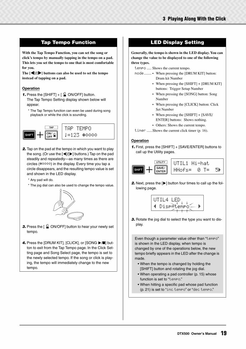
Tap Tempo Function
With the Tap Tempo Function, you can set the song or click’s tempo by manually tapping in the tempo on a pad. This lets you set the tempo to one that is most comfortable for you.
The [<<<<]/[>>>>] buttons can also be used to set the tempo instead of tapping on a pad.
Operation
1. Press the [SHIFT] + [ ON/OFF] button.The Tap Tempo Setting display shown below will appear.
* The Tap Tempo function can even be used during song playback or while the click is sounding.
2. Tap on the pad at the tempo in which you want to play the song. (Or use the [<]/[>] buttons.) Tap on the pad steadily and repeatedly—as many times as there are circles (≠ªªªª) in the display. Every time you tap a circle disappears, and the resulting tempo value is set and shown in the LED display.
* Any pad will do.
* The jog dial can also be used to change the tempo value.
3. Press the [ ON/OFF] button to hear your newly set tempo.
4. Press the [DRUM KIT], [CLICK], or [SONG >/] but-ton to exit from the Tap Tempo page. In the Click Set-ting page and Song Select page, the tempo is set to the newly selected tempo. If the song or click is play-ing, the tempo will immediately change to the new tempo.
TAP~TEMPO
¤=123~≠ªªªª
LED Display Setting
Generally, the tempo is shown in the LED display. You can change the value to be displayed to one of the following three types.
tempo ..... Shows the current tempo.mode ........ • When pressing the [DRUM KIT] button:
Drum kit Number
• When pressing the [SHIFT] + [DRUM KIT] buttons: Trigger Setup Number
• When pressing the [SONG] button: Song Number
• When pressing the [CLICK] button: Click Set Number
• When pressing the [SHIFT] + [SAVE/ENTER] buttons: Shows nothing.
• Others: Shows the current tempo.
timer ......Shows the current click timer (p. 16).
Operation
1. First, press the [SHIFT] + [SAVE/ENTER] buttons to call up the Utility pages.
2. Next, press the [>] button four times to call up the fol-lowing page.
3. Rotate the jog dial to select the type you want to dis-play.
UTIL1~Hi-hat
HHofs=~~0~T=~~5‚
UTIL4~LED
”~Disp=tempo~~~‚
Even though a parameter value other than “tempo” is shown in the LED display, when tempo is changed by one of the operations below, the new tempo briefly appears in the LED after the change is made.
• When the tempo is changed by holding the [SHIFT] button and rotating the jog dial.
• When operating a pad controller (p. 15) whose function is set to “tempo.”
• When hitting a specific pad whose pad function (p. 21) is set to “inc tempo” or “dec tempo.”
19DTX500 Owner’s Manual
4 Playing Along With a Song
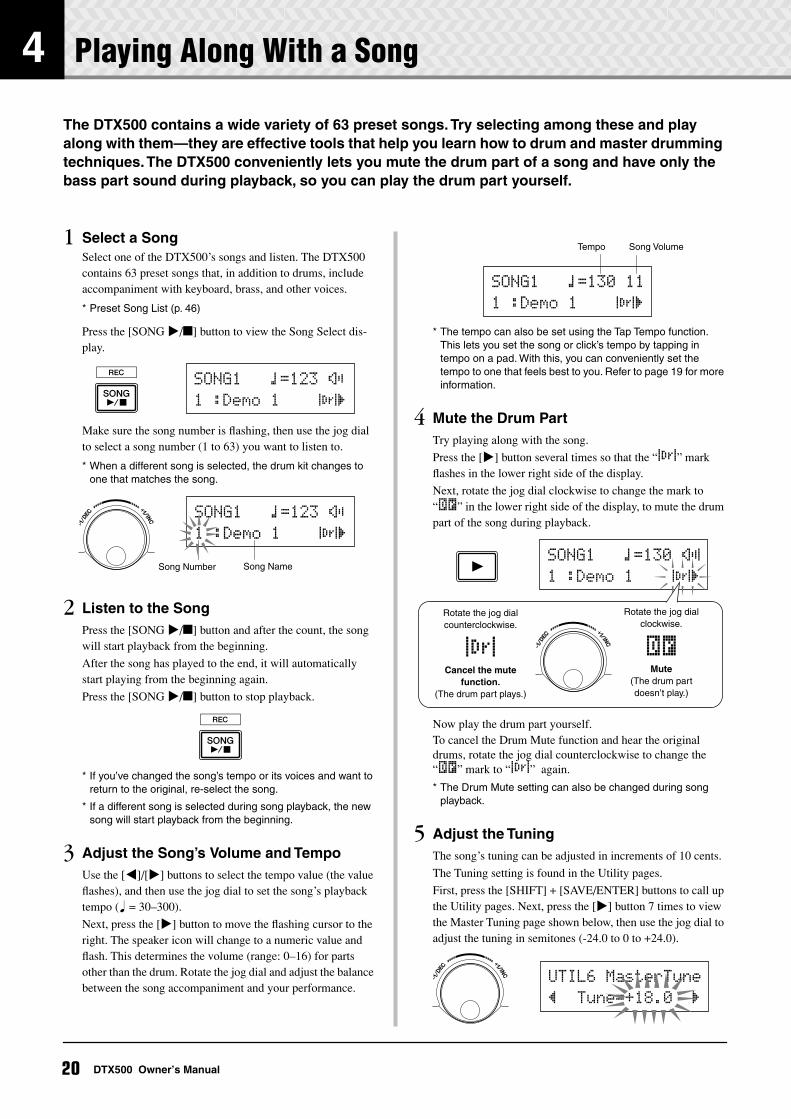
The DTX500 contains a wide variety of 63 preset songs. Try selecting among these and play along with them—they are effective tools that help you learn how to drum and master drumming techniques. The DTX500 conveniently lets you mute the drum part of a song and have only the bass part sound during playback, so you can play the drum part yourself.
1 Select a SongSelect one of the DTX500’s songs and listen. The DTX500 contains 63 preset songs that, in addition to drums, include accompaniment with keyboard, brass, and other voices.
* Preset Song List (p. 46)
Press the [SONG >/] button to view the Song Select dis-play.
Make sure the song number is flashing, then use the jog dial to select a song number (1 to 63) you want to listen to.
* When a different song is selected, the drum kit changes to one that matches the song.
2 Listen to the SongPress the [SONG >/] button and after the count, the song will start playback from the beginning.
After the song has played to the end, it will automatically start playing from the beginning again.
Press the [SONG >/] button to stop playback.
* If you’ve changed the song’s tempo or its voices and want to return to the original, re-select the song.
* If a different song is selected during song playback, the new song will start playback from the beginning.
3 Adjust the Song’s Volume and TempoUse the [<]/[>] buttons to select the tempo value (the value flashes), and then use the jog dial to set the song’s playback tempo (q = 30–300).
Next, press the [>] button to move the flashing cursor to the right. The speaker icon will change to a numeric value and flash. This determines the volume (range: 0–16) for parts other than the drum. Rotate the jog dial and adjust the balance between the song accompaniment and your performance.
* The tempo can also be set using the Tap Tempo function. This lets you set the song or click’s tempo by tapping in tempo on a pad. With this, you can conveniently set the tempo to one that feels best to you. Refer to page 19 for more information.
4 Mute the Drum PartTry playing along with the song.
Press the [>] button several times so that the “∞¢” mark flashes in the lower right side of the display.
Next, rotate the jog dial clockwise to change the mark to “˚¡” in the lower right side of the display, to mute the drum part of the song during playback.
Now play the drum part yourself.To cancel the Drum Mute function and hear the original drums, rotate the jog dial counterclockwise to change the “˚¡” mark to “∞¢” again.
* The Drum Mute setting can also be changed during song playback.
5 Adjust the TuningThe song’s tuning can be adjusted in increments of 10 cents.
The Tuning setting is found in the Utility pages.
First, press the [SHIFT] + [SAVE/ENTER] buttons to call up the Utility pages. Next, press the [>] button 7 times to view the Master Tuning page shown below, then use the jog dial to adjust the tuning in semitones (-24.0 to 0 to +24.0).
SONG1~~~⁄=123~÷ç
1~:Demo~1~~~~∞¢‚
Song Number
SONG1~~~⁄=123~÷ç
1~:Demo~1~~~~∞¢‚
Song Name
Tempo Song Volume
SONG1~~~⁄=130~11
1~:Demo~1~~~~∞¢‚
SONG1~~~⁄=130~÷›
1~:Demo~1~~~~∞¢‚
Rotate the jog dial clockwise.
˚¡Mute
(The drum part doesn’t play.)
Rotate the jog dial counterclockwise.
∞¢Cancel the mute
function.(The drum part plays.)
UTIL6~MasterTune
”~~Tune=+18.0~~‚
20 DTX500 Owner’s Manual
4 Playing Along With a Song
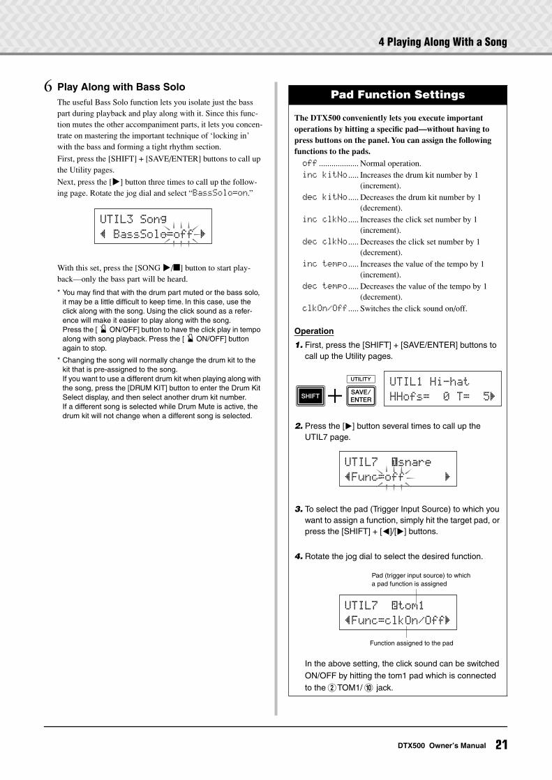
6 Play Along with Bass SoloThe useful Bass Solo function lets you isolate just the bass part during playback and play along with it. Since this func-tion mutes the other accompaniment parts, it lets you concen-trate on mastering the important technique of ‘locking in’ with the bass and forming a tight rhythm section.
First, press the [SHIFT] + [SAVE/ENTER] buttons to call up the Utility pages.
Next, press the [>] button three times to call up the follow-ing page. Rotate the jog dial and select “BassSolo=on.”
With this set, press the [SONG >/] button to start play-back—only the bass part will be heard.
* You may find that with the drum part muted or the bass solo, it may be a little difficult to keep time. In this case, use the click along with the song. Using the click sound as a refer-ence will make it easier to play along with the song.Press the [ ON/OFF] button to have the click play in tempo along with song playback. Press the [ ON/OFF] button again to stop.
* Changing the song will normally change the drum kit to the kit that is pre-assigned to the song.If you want to use a different drum kit when playing along with the song, press the [DRUM KIT] button to enter the Drum Kit Select display, and then select another drum kit number.If a different song is selected while Drum Mute is active, the drum kit will not change when a different song is selected.
UTIL3~Song
”~BassSolo=off~‚
Pad Function Settings
The DTX500 conveniently lets you execute important operations by hitting a specific pad—without having to press buttons on the panel. You can assign the following functions to the pads.
off ................... Normal operation.inc~kitNo ..... Increases the drum kit number by 1
(increment).dec~kitNo ..... Decreases the drum kit number by 1
(decrement).inc~clkNo ..... Increases the click set number by 1
(increment).dec~clkNo ..... Decreases the click set number by 1
(decrement).inc~tempo ..... Increases the value of the tempo by 1
(increment).dec~tempo ..... Decreases the value of the tempo by 1
(decrement).clkOn/Off ..... Switches the click sound on/off.
Operation
1. First, press the [SHIFT] + [SAVE/ENTER] buttons to call up the Utility pages.
2. Press the [>] button several times to call up the UTIL7 page.
3. To select the pad (Trigger Input Source) to which you want to assign a function, simply hit the target pad, or press the [SHIFT] + [<]/[>] buttons.
4. Rotate the jog dial to select the desired function.
In the above setting, the click sound can be switched ON/OFF by hitting the tom1 pad which is connected to the 2TOM1/ 0 jack.
UTIL1~Hi-hat
HHofs=~~0~T=~~5‚
UTIL7~~ƒsnare
”Func=off~~~~~~‚
UTIL7~~™tom1
”Func=clkOn/Off‚
Pad (trigger input source) to which a pad function is assigned
Function assigned to the pad
21DTX500 Owner’s Manual
5 Using the Groove Check Function
Another highly useful feature of the DTX500 is the Groove Check function. As you play along with a song or the click, Groove Check compares your timing with the song or click playback and lets you know how accurate your playing is.The related Rhythm Gate function—in which the sound is cancelled if your timing is off—also offers you a great way to improve your technique.
Groove Check Mode
The Groove Check function has the following two modes.
Numeric Display Mode
In this mode, the accuracy of your drum hits is shown in numeric display.The aspects shown in the numeric display are the average inaccuracy in the timing of each hit and the deviation in tim-ing inaccuracy of all hits. To use this mode, select one of the modes other than “Challenge” from the Rhythm Gate set-tings in the GRV2 page.
* Hit timing display
If your timing is slow or you’re dragging the beat, the mark will move to the right side of the display. If your timing is fast or you’re pushing the beat, the mark will move to the left.
* Rhythm Gate range
With the Rhythm Gate function, sound is produced only if the hit is within the specified range, and sound is not produced if the hit is outside this range. The range of Rhythm Gate can be selected from three levels according to the degree of difficulty and if this is set to off, sound is always produced, no matter what your timing is. The selected range is shown in the lower side of the upper half of the display.
* Tempo
The jog dial can be used to adjust the tempo for the song or click from 30 to 300.
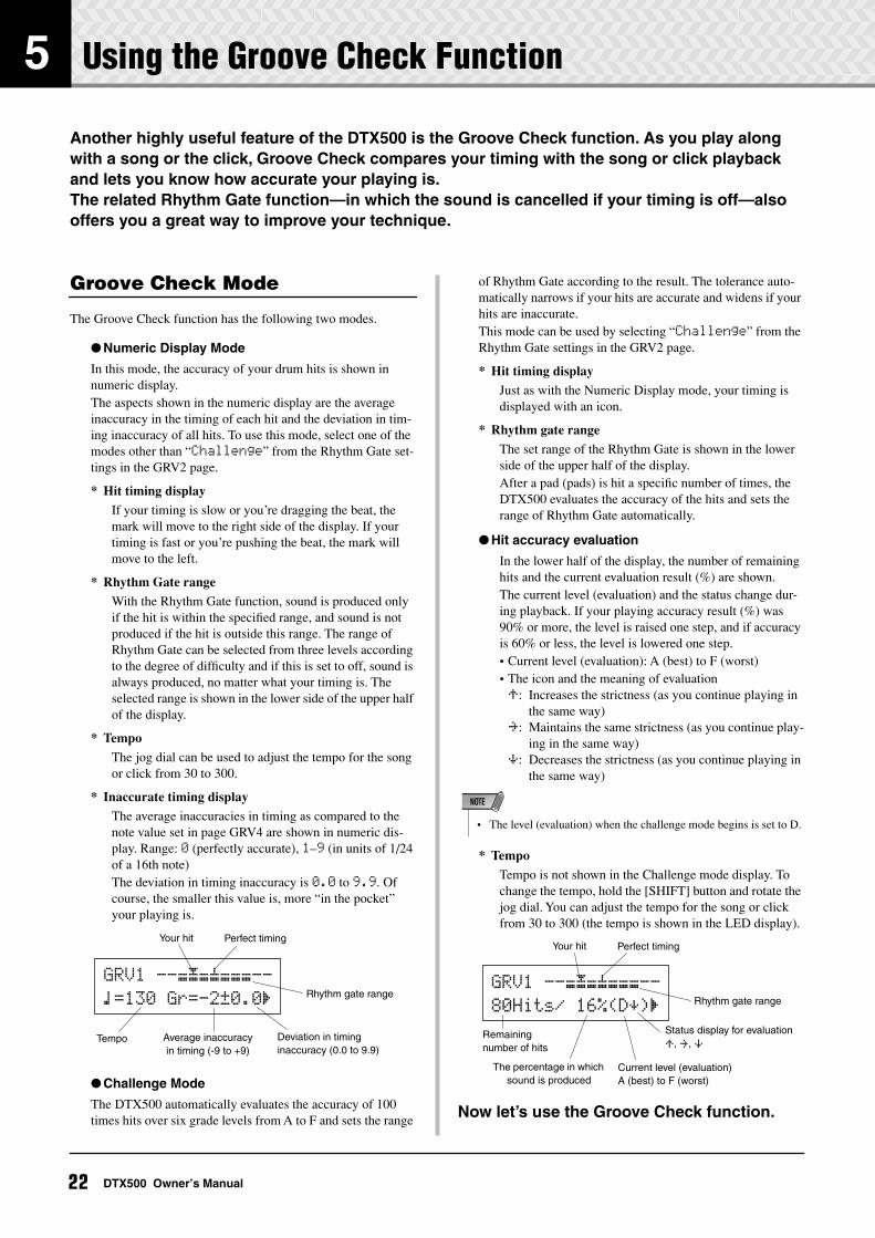
* Inaccurate timing display
The average inaccuracies in timing as compared to the note value set in page GRV4 are shown in numeric dis-play. Range: 0 (perfectly accurate), 1–9 (in units of 1/24 of a 16th note)The deviation in timing inaccuracy is 0.0 to 9.9. Of course, the smaller this value is, more “in the pocket” your playing is.
Challenge Mode
The DTX500 automatically evaluates the accuracy of 100 times hits over six grade levels from A to F and sets the range
of Rhythm Gate according to the result. The tolerance auto-matically narrows if your hits are accurate and widens if your hits are inaccurate.This mode can be used by selecting “Challenge” from the Rhythm Gate settings in the GRV2 page.
* Hit timing display
Just as with the Numeric Display mode, your timing is displayed with an icon.
* Rhythm gate range
The set range of the Rhythm Gate is shown in the lower side of the upper half of the display. After a pad (pads) is hit a specific number of times, the DTX500 evaluates the accuracy of the hits and sets the range of Rhythm Gate automatically.
Hit accuracy evaluation
In the lower half of the display, the number of remaining hits and the current evaluation result (%) are shown.The current level (evaluation) and the status change dur-ing playback. If your playing accuracy result (%) was 90% or more, the level is raised one step, and if accuracy is 60% or less, the level is lowered one step.• Current level (evaluation): A (best) to F (worst)• The icon and the meaning of evaluationÃ: Increases the strictness (as you continue playing in
the same way)≥: Maintains the same strictness (as you continue play-
ing in the same way)À: Decreases the strictness (as you continue playing in
the same way)
* Tempo
Tempo is not shown in the Challenge mode display. To change the tempo, hold the [SHIFT] button and rotate the jog dial. You can adjust the tempo for the song or click from 30 to 300 (the tempo is shown in the LED display).
Now let’s use the Groove Check function.
Your hit
Deviation in timing inaccuracy (0.0 to 9.9)
Tempo Average inaccuracy in timing (-9 to +9)
GRV1~--æ√æ’æææ--
⁄=130~Gr=-2œ0.0‚ Rhythm gate range
Perfect timing
• The level (evaluation) when the challenge mode begins is set to D.
NOTE
Status display for evaluation
Ã, ≥, ÀRemaining number of hits
The percentage in which sound is produced
GRV1~--æ√æ’æææ--
80Hits/~16%(DÀ)‚ Rhythm gate range
Current level (evaluation)A (best) to F (worst)
Your hit Perfect timing
22 DTX500 Owner’s Manual
5 Using the Groove Check Function
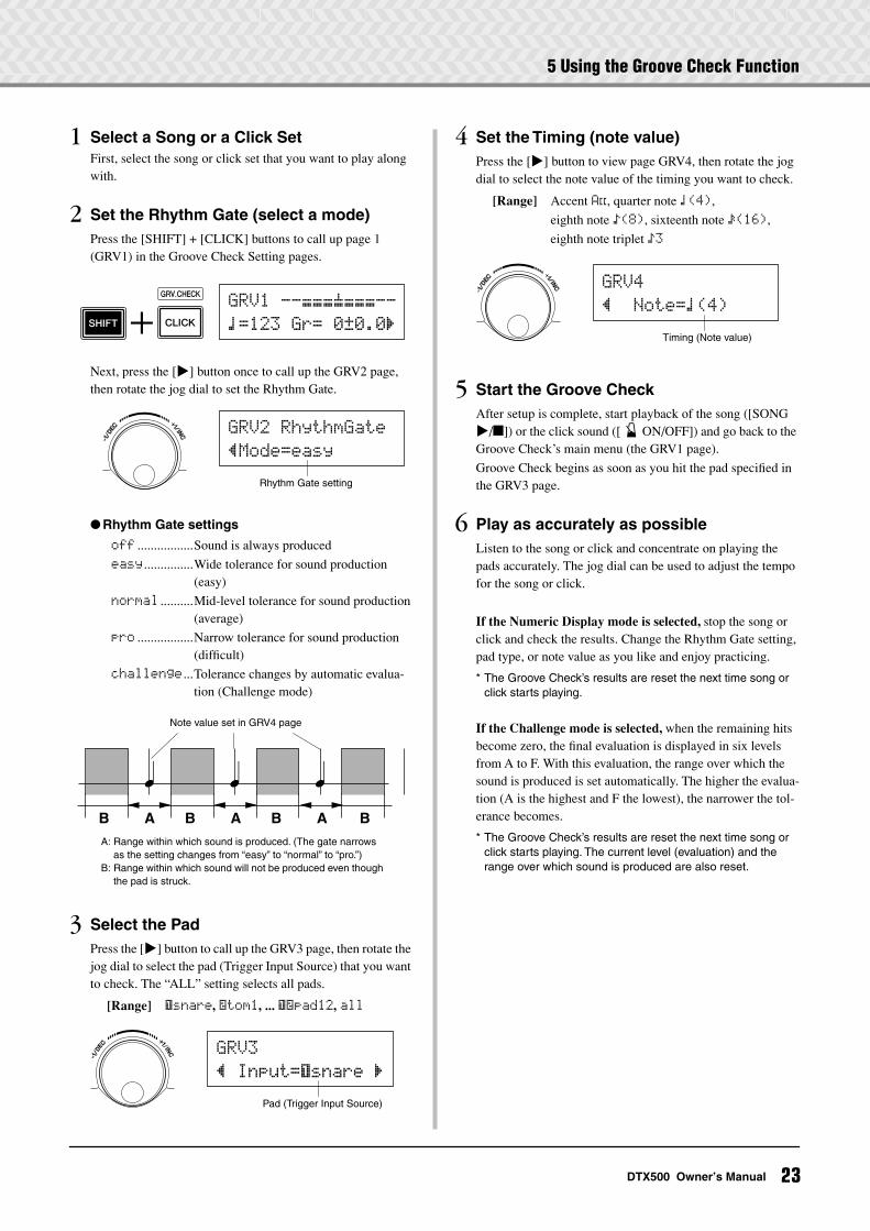
1 Select a Song or a Click SetFirst, select the song or click set that you want to play along with.
2 Set the Rhythm Gate (select a mode)Press the [SHIFT] + [CLICK] buttons to call up page 1 (GRV1) in the Groove Check Setting pages.
Next, press the [>] button once to call up the GRV2 page, then rotate the jog dial to set the Rhythm Gate.
Rhythm Gate settings
off .................Sound is always produced
easy ...............Wide tolerance for sound production (easy)
normal ..........Mid-level tolerance for sound production (average)
pro .................Narrow tolerance for sound production (difficult)
challenge ...Tolerance changes by automatic evalua-tion (Challenge mode)
3 Select the PadPress the [>] button to call up the GRV3 page, then rotate the jog dial to select the pad (Trigger Input Source) that you want to check. The “ALL” setting selects all pads.
[Range] ƒsnare, ™tom1, ... ƒ™pad12, all
4 Set the Timing (note value)Press the [>] button to view page GRV4, then rotate the jog dial to select the note value of the timing you want to check.
[Range] Accent A˘, quarter note ⁄(4),
eighth note Ö(8), sixteenth note Ü(16),
eighth note triplet Ö3
5 Start the Groove CheckAfter setup is complete, start playback of the song ([SONG >/]) or the click sound ([ ON/OFF]) and go back to the Groove Check’s main menu (the GRV1 page).
Groove Check begins as soon as you hit the pad specified in the GRV3 page.
6 Play as accurately as possibleListen to the song or click and concentrate on playing the pads accurately. The jog dial can be used to adjust the tempo for the song or click.
If the Numeric Display mode is selected, stop the song or click and check the results. Change the Rhythm Gate setting, pad type, or note value as you like and enjoy practicing.
* The Groove Check’s results are reset the next time song or click starts playing.
If the Challenge mode is selected, when the remaining hits become zero, the final evaluation is displayed in six levels from A to F. With this evaluation, the range over which the sound is produced is set automatically. The higher the evalua-tion (A is the highest and F the lowest), the narrower the tol-erance becomes.
* The Groove Check’s results are reset the next time song or click starts playing. The current level (evaluation) and the range over which sound is produced are also reset.
GRV1~--æææ’æææ--
⁄=123~Gr=~0œ0.0‚
GRV2~RhythmGate
”Mode=easy
Rhythm Gate setting
A A AB B B B
Note value set in GRV4 page
A: Range within which sound is produced. (The gate narrows as the setting changes from “easy” to “normal” to “pro.”)
B: Range within which sound will not be produced even though the pad is struck.
GRV3
”~Input=ƒsnare~‚
Pad (Trigger Input Source)
GRV4
”~~Note=⁄(4)
Timing (Note value)
23DTX500 Owner’s Manual
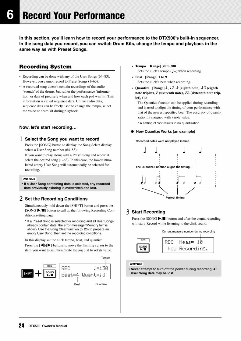
6 Record Your Performance
In this section, you’ll learn how to record your performance to the DTX500’s built-in sequencer. In the song data you record, you can switch Drum Kits, change the tempo and playback in the same way as with Preset Songs.
Recording System
• Recording can be done with any of the User Songs (64–83). However, you cannot record to Preset Songs (1–63).
• A recorded song doesn’t contain recordings of the audio ‘sounds’ of the drums, but rather the performance ‘informa-tion’ or data of precisely when and how each pad was hit. This information is called sequence data. Unlike audio data, sequence data can be freely used to change the tempo, select the voice or drum kit during playback.
Now, let’s start recording…
1 Select the Song you want to recordPress the [SONG] button to display the Song Select display, select a User Song number (64–83).
If you want to play along with a Preset Song and record it, select the desired song (1–63). In this case, the lowest num-bered empty User Song will automatically be selected for recording.
2 Set the Recording ConditionsSimultaneously hold down the [SHIFT] button and press the [SONG >/] button to call up the following Recording Con-ditions setting page.
* If a Preset Song is selected for recording and all User Songs already contain data, the error message “Memory full” is shown. Use the Song Clear function (p. 25) to prepare an empty User Song, then set the recording conditions.
In this display set the click tempo, beat, and quantize.
Press the [<]/[>] buttons to move the flashing cursor to the item you want to set, then rotate the jog dial to set its value.
• Tempo [Range] 30 to 300Sets the click’s tempo (q=) when recording.
• Beat [Range] 1 to 9Sets the click’s beat when recording.
• Quantize [Range] ⁄, ⁄3, Ö (eighth note), Ö3 (eighth note triplet), Ü (sixteenth note), Ü3 (sixteenth note trip-let), no
The Quantize function can be applied during recording and is used to align the timing of your performance with that of the nearest specified beat. The accuracy of quanti-zation is assigned with a note value.
* A setting of “no” results in no quantization.
3 Start RecordingPress the [SONG >/] button and after the count, recording will start. Record while listening to the click sound.
• If a User Song containing data is selected, any recorded data previously existing is overwritten and lost.
NOTICE
Quantize
Tempo
Beat
REC~~~~~~~~⁄=130
Beat=4~Quant=⁄3
• Never attempt to turn off the power during recording. All User Song data may be lost.
How Quantize Works (an example)
Recorded notes were not played in time.
The Quantize Function aligns the timing.
Perfect timing
REC~~Meas=~10
~Now~Recording.
Current measure number during recording
NOTICE
24 DTX500 Owner’s Manual
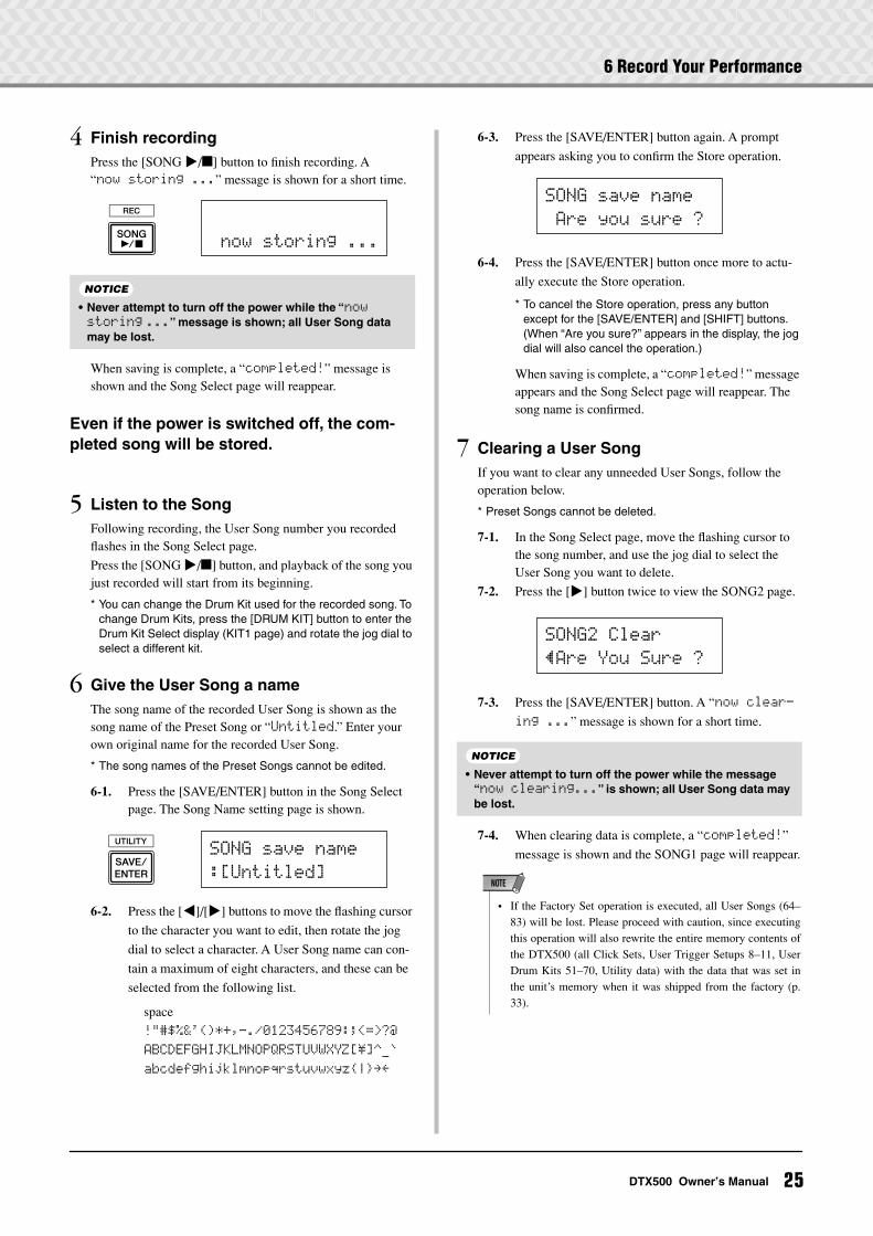
6 Record Your Performance
4 Finish recordingPress the [SONG >/] button to finish recording. A “now~storing~...” message is shown for a short time.
When saving is complete, a “completed!” message is shown and the Song Select page will reappear.
Even if the power is switched off, the com-pleted song will be stored.
5 Listen to the SongFollowing recording, the User Song number you recorded flashes in the Song Select page.
Press the [SONG >/] button, and playback of the song you just recorded will start from its beginning.
* You can change the Drum Kit used for the recorded song. To change Drum Kits, press the [DRUM KIT] button to enter the Drum Kit Select display (KIT1 page) and rotate the jog dial to select a different kit.
6 Give the User Song a nameThe song name of the recorded User Song is shown as the song name of the Preset Song or “Untitled.” Enter your own original name for the recorded User Song.
* The song names of the Preset Songs cannot be edited.
6-1. Press the [SAVE/ENTER] button in the Song Select page. The Song Name setting page is shown.
6-2. Press the [<]/[>] buttons to move the flashing cursor
to the character you want to edit, then rotate the jog
dial to select a character. A User Song name can con-
tain a maximum of eight characters, and these can be
selected from the following list.
6-3. Press the [SAVE/ENTER] button again. A prompt
appears asking you to confirm the Store operation.
6-4. Press the [SAVE/ENTER] button once more to actu-
ally execute the Store operation.
* To cancel the Store operation, press any button except for the [SAVE/ENTER] and [SHIFT] buttons. (When “Are you sure?” appears in the display, the jog dial will also cancel the operation.)
When saving is complete, a “completed!” message appears and the Song Select page will reappear. The song name is confirmed.
7 Clearing a User SongIf you want to clear any unneeded User Songs, follow the operation below.
* Preset Songs cannot be deleted.
7-1. In the Song Select page, move the flashing cursor to the song number, and use the jog dial to select the User Song you want to delete.
7-2. Press the [>] button twice to view the SONG2 page.
7-3. Press the [SAVE/ENTER] button. A “now~clear-
ing~...” message is shown for a short time.
7-4. When clearing data is complete, a “completed!”
message is shown and the SONG1 page will reappear.
• Never attempt to turn off the power while the “now storing ...” message is shown; all User Song data may be lost.
~now~storing~...
NOTICE
SONG~save~name
:[Untitled]
space
!"#$%&'()*+,-./0123456789:;<=>?@
ABCDEFGHIJKLMNOPQRSTUVWXYZ[\]^_`
abcdefghijklmnopqrstuvwxyz|≥≤
• Never attempt to turn off the power while the message “now clearing...” is shown; all User Song data may be lost.
SONG~save~name
~Are~you~sure~?
SONG2~Clear
”Are~You~Sure~?
NOTICE
• If the Factory Set operation is executed, all User Songs (64–83) will be lost. Please proceed with caution, since executingthis operation will also rewrite the entire memory contents ofthe DTX500 (all Click Sets, User Trigger Setups 8–11, UserDrum Kits 51–70, Utility data) with the data that was set inthe unit’s memory when it was shipped from the factory (p.33).
NOTE
25DTX500 Owner’s Manual
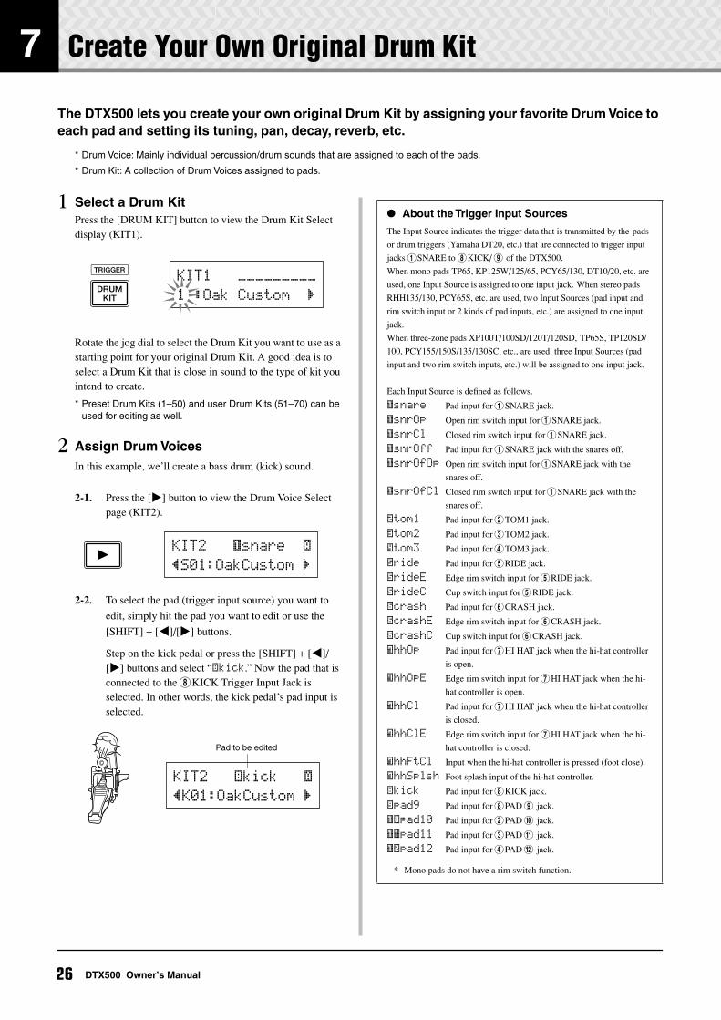
7 Create Your Own Original Drum Kit
The DTX500 lets you create your own original Drum Kit by assigning your favorite Drum Voice to each pad and setting its tuning, pan, decay, reverb, etc.
* Drum Voice: Mainly individual percussion/drum sounds that are assigned to each of the pads.
* Drum Kit: A collection of Drum Voices assigned to pads.
1 Select a Drum KitPress the [DRUM KIT] button to view the Drum Kit Select display (KIT1).
Rotate the jog dial to select the Drum Kit you want to use as a starting point for your original Drum Kit. A good idea is to select a Drum Kit that is close in sound to the type of kit you intend to create.
* Preset Drum Kits (1–50) and user Drum Kits (51–70) can be used for editing as well.
2 Assign Drum VoicesIn this example, we’ll create a bass drum (kick) sound.
2-1. Press the [>] button to view the Drum Voice Select page (KIT2).
2-2. To select the pad (trigger input source) you want to
edit, simply hit the pad you want to edit or use the
[SHIFT] + [<]/[>] buttons.
Step on the kick pedal or press the [SHIFT] + [<]/[>] buttons and select “äkick.” Now the pad that is connected to the 8KICK Trigger Input Jack is selected. In other words, the kick pedal’s pad input is selected.
KIT1~~~ååååååååå
1~:Oak~Custom~~‚
KIT2~~~ƒsnare~~˙
”S01:OakCustom~‚
Pad to be edited
KIT2~~~äkick~~~˙
”K01:OakCustom~‚
About the Trigger Input Sources
The Input Source indicates the trigger data that is transmitted by the pads
or drum triggers (Yamaha DT20, etc.) that are connected to trigger input
jacks 1SNARE to 8KICK/ 9 of the DTX500.
When mono pads TP65, KP125W/125/65, PCY65/130, DT10/20, etc. are
used, one Input Source is assigned to one input jack. When stereo pads
RHH135/130, PCY65S, etc. are used, two Input Sources (pad input and
rim switch input or 2 kinds of pad inputs, etc.) are assigned to one input
jack.
When three-zone pads XP100T/100SD/120T/120SD, TP65S, TP120SD/
100, PCY155/150S/135/130SC, etc., are used, three Input Sources (pad
input and two rim switch inputs, etc.) will be assigned to one input jack.
Each Input Source is defined as follows.
ƒsnare Pad input for 1SNARE jack.
ƒsnrOp Open rim switch input for 1SNARE jack.
ƒsnrCl Closed rim switch input for 1SNARE jack.
ƒsnrOff Pad input for 1SNARE jack with the snares off.
ƒsnrOfOp Open rim switch input for 1SNARE jack with the
snares off.
ƒsnrOfCl Closed rim switch input for 1SNARE jack with the
snares off.
™tom1 Pad input for 2TOM1 jack.
£tom2 Pad input for 3TOM2 jack.
Ωtom3 Pad input for 4TOM3 jack.
•ride Pad input for 5RIDE jack.
•rideE Edge rim switch input for 5RIDE jack.
•rideC Cup switch input for 5RIDE jack.
öcrash Pad input for 6CRASH jack.
öcrashE Edge rim switch input for 6CRASH jack.
öcrashC Cup switch input for 6CRASH jack.
ühhOp Pad input for 7HI HAT jack when the hi-hat controller
is open.
ühhOpE Edge rim switch input for 7HI HAT jack when the hi-
hat controller is open.
ühhCl Pad input for 7HI HAT jack when the hi-hat controller
is closed.
ühhClE Edge rim switch input for 7HI HAT jack when the hi-
hat controller is closed.
ühhFtCl Input when the hi-hat controller is pressed (foot close).
ühhSplsh Foot splash input of the hi-hat controller.
äkick Pad input for 8KICK jack.
“pad9 Pad input for 8PAD 9 jack.
ƒπpad10 Pad input for 2PAD 0 jack.
ƒƒpad11 Pad input for 3PAD ! jack.
Īpad12 Pad input for 4PAD @ jack.
* Mono pads do not have a rim switch function.
26 DTX500 Owner’s Manual
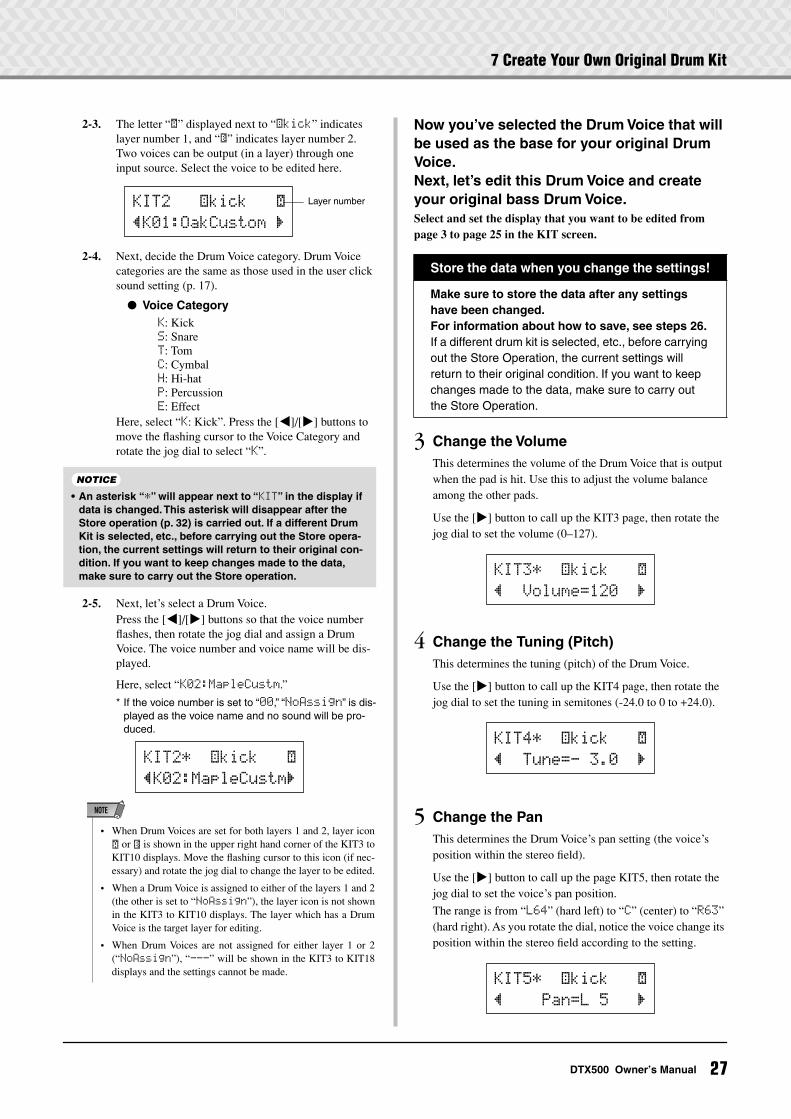
7 Create Your Own Original Drum Kit
2-3. The letter “˙” displayed next to “äkick” indicates layer number 1, and “¶” indicates layer number 2. Two voices can be output (in a layer) through one input source. Select the voice to be edited here.
2-4. Next, decide the Drum Voice category. Drum Voice categories are the same as those used in the user click sound setting (p. 17).
Voice CategoryK: KickS: SnareT: TomC: CymbalH: Hi-hatP: PercussionE: Effect
Here, select “K: Kick”. Press the [<]/[>] buttons to move the flashing cursor to the Voice Category and rotate the jog dial to select “K”.
2-5. Next, let’s select a Drum Voice.Press the [<]/[>] buttons so that the voice number flashes, then rotate the jog dial and assign a Drum Voice. The voice number and voice name will be dis-played.
Here, select “K02:MapleCustm.”
* If the voice number is set to “00,” “NoAssign” is dis-played as the voice name and no sound will be pro-duced.
Now you’ve selected the Drum Voice that will be used as the base for your original Drum Voice.Next, let’s edit this Drum Voice and create your original bass Drum Voice.Select and set the display that you want to be edited from page 3 to page 25 in the KIT screen.
3 Change the VolumeThis determines the volume of the Drum Voice that is output when the pad is hit. Use this to adjust the volume balance among the other pads.
Use the [>] button to call up the KIT3 page, then rotate the jog dial to set the volume (0–127).
4 Change the Tuning (Pitch)This determines the tuning (pitch) of the Drum Voice.
Use the [>] button to call up the KIT4 page, then rotate the jog dial to set the tuning in semitones (-24.0 to 0 to +24.0).
5 Change the PanThis determines the Drum Voice’s pan setting (the voice’s position within the stereo field).
Use the [>] button to call up the page KIT5, then rotate the jog dial to set the voice’s pan position.
The range is from “L64” (hard left) to “C” (center) to “R63” (hard right). As you rotate the dial, notice the voice change its position within the stereo field according to the setting.
• An asterisk “*” will appear next to “KIT” in the display if data is changed. This asterisk will disappear after the Store operation (p. 32) is carried out. If a different Drum Kit is selected, etc., before carrying out the Store opera-tion, the current settings will return to their original con-dition. If you want to keep changes made to the data, make sure to carry out the Store operation.
KIT2~~~äkick~~~˙
”K01:OakCustom~‚
Layer number
NOTICE
KIT2*~~äkick~~~˙
”K02:MapleCustm‚
• When Drum Voices are set for both layers 1 and 2, layer icon˙ or ¶ is shown in the upper right hand corner of the KIT3 toKIT10 displays. Move the flashing cursor to this icon (if nec-essary) and rotate the jog dial to change the layer to be edited.
• When a Drum Voice is assigned to either of the layers 1 and 2(the other is set to “NoAssign”), the layer icon is not shownin the KIT3 to KIT10 displays. The layer which has a DrumVoice is the target layer for editing.
• When Drum Voices are not assigned for either layer 1 or 2(“NoAssign”), “---” will be shown in the KIT3 to KIT18displays and the settings cannot be made.
NOTE
Store the data when you change the settings!
Make sure to store the data after any settings have been changed. For information about how to save, see steps 26.If a different drum kit is selected, etc., before carrying out the Store Operation, the current settings will return to their original condition. If you want to keep changes made to the data, make sure to carry out the Store Operation.
KIT3*~~äkick~~~˙
”~~Volume=120~~‚
KIT4*~~äkick~~~˙
”~~Tune=-~3.0~~‚
KIT5*~~äkick~~~˙
”~~~~Pan=L~5~~~‚
27DTX500 Owner’s Manual
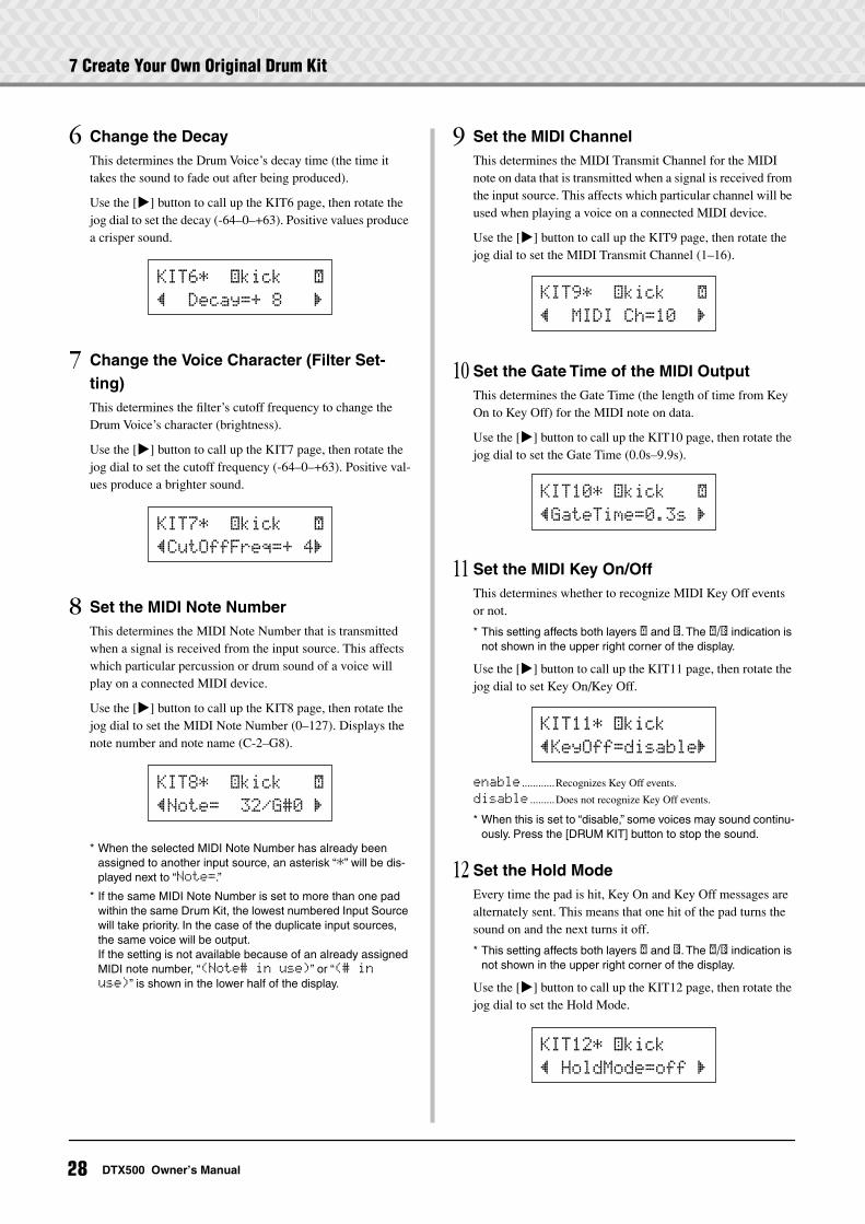
7 Create Your Own Original Drum Kit
6 Change the DecayThis determines the Drum Voice’s decay time (the time it takes the sound to fade out after being produced).
Use the [>] button to call up the KIT6 page, then rotate the jog dial to set the decay (-64–0–+63). Positive values produce a crisper sound.
7 Change the Voice Character (Filter Set-ting)This determines the filter’s cutoff frequency to change the Drum Voice’s character (brightness).
Use the [>] button to call up the KIT7 page, then rotate the jog dial to set the cutoff frequency (-64–0–+63). Positive val-ues produce a brighter sound.
8 Set the MIDI Note NumberThis determines the MIDI Note Number that is transmitted when a signal is received from the input source. This affects which particular percussion or drum sound of a voice will play on a connected MIDI device.
Use the [>] button to call up the KIT8 page, then rotate the jog dial to set the MIDI Note Number (0–127). Displays the note number and note name (C-2–G8).
* When the selected MIDI Note Number has already been assigned to another input source, an asterisk “*” will be dis-played next to “Note=.”
* If the same MIDI Note Number is set to more than one pad within the same Drum Kit, the lowest numbered Input Source will take priority. In the case of the duplicate input sources, the same voice will be output.If the setting is not available because of an already assigned MIDI note number, “(Note# in use)” or “(# in use)” is shown in the lower half of the display.
9 Set the MIDI ChannelThis determines the MIDI Transmit Channel for the MIDI note on data that is transmitted when a signal is received from the input source. This affects which particular channel will be used when playing a voice on a connected MIDI device.
Use the [>] button to call up the KIT9 page, then rotate the jog dial to set the MIDI Transmit Channel (1–16).
10 Set the Gate Time of the MIDI OutputThis determines the Gate Time (the length of time from Key On to Key Off) for the MIDI note on data.
Use the [>] button to call up the KIT10 page, then rotate the jog dial to set the Gate Time (0.0s–9.9s).
11 Set the MIDI Key On/OffThis determines whether to recognize MIDI Key Off events or not.
* This setting affects both layers ˙ and ¶. The ˙/¶ indication is not shown in the upper right corner of the display.
Use the [>] button to call up the KIT11 page, then rotate the jog dial to set Key On/Key Off.
enable ............Recognizes Key Off events.
disable .........Does not recognize Key Off events.
* When this is set to “disable,” some voices may sound continu-ously. Press the [DRUM KIT] button to stop the sound.
12 Set the Hold ModeEvery time the pad is hit, Key On and Key Off messages are alternately sent. This means that one hit of the pad turns the sound on and the next turns it off.
* This setting affects both layers ˙ and ¶. The ˙/¶ indication is not shown in the upper right corner of the display.
Use the [>] button to call up the KIT12 page, then rotate the jog dial to set the Hold Mode.
KIT6*~~äkick~~~˙
”~~Decay=+~8~~~‚
KIT7*~~äkick~~~˙
”CutOffFreq=+~4‚
KIT8*~~äkick~~~˙
”Note=~~32/G#0~‚
KIT9*~~äkick~~~˙
”~~MIDI~Ch=10~~‚
KIT10*~äkick~~~˙
”GateTime=0.3s~‚
KIT11*~äkick
”KeyOff=disable‚
KIT12*~äkick
”~HoldMode=off~‚
28 DTX500 Owner’s Manual
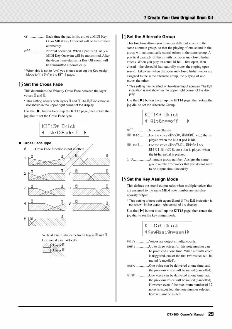
7 Create Your Own Original Drum Kit
on ................... Each time the pad is hit, either a MIDI Key On or MIDI Key Off event will be transmitted alternately.
off................. Normal operation. When a pad is hit, only a MIDI Key On event will be transmitted. After the decay time elapses, a Key Off event will be transmitted automatically.
* When this is set to “on,” you should also set the Key Assign Mode to “high” in the KIT15 page.
13 Set the Cross FadeThis determines the Velocity Cross Fade between the layer voices ˙ and ¶.
* This setting affects both layers ˙ and ¶. The ˙/¶ indication is not shown in the upper right corner of the display.
Use the [>] button to call up the KIT13 page, then rotate the jog dial to set the Cross Fade type.
Cross Fade Type
0 .........Cross Fade function is not in effect.
14 Set the Alternate GroupThis function allows you to assign different voices to the same alternate group, so that the playing of one sound in the group will automatically cancel others in the same group. A practical example of this is with the open and closed hi-hat voices. When you play an actual hi-hat—first open, then closed—the closed hi-hat naturally mutes the ringing open sound. Likewise, when the open and closed hi-hat voices are assigned to the same alternate group, the playing of one mutes the other.
* This setting has no affect on two-layer input sources. The ˙/¶ indication is not shown in the upper right corner of the dis-play.
Use the [>] button to call up the KIT14 page, then rotate the jog dial to set the Alternate Group.
off .................No cancellation
HH~pad ..........For the voice (ühhOp, ühhOpE, etc.) that is played when the hi-hat pad is hit.
HH~pdl ..........For the voice (ühhFtCl, ühhSplsh, ühhCl, ühhClE, etc.) that is played when the hi-hat pedal is pressed.
1–9 ..................Alternate group number. Assigns the same group number for voices that you do not want to be output simultaneously.
15 Set the Key Assign ModeThis defines the sound output rules when multiple voices that are assigned to the same MIDI note number are simulta-neously output.
* This setting affects both layers ˙ and ¶. The ˙/¶ indication is not shown in the upper right corner of the display.
Use the [>] button to call up the KIT15 page, then rotate the jog dial to set the key assign mode.
poly ...............Voices are output simultaneously.
semi ...............Up to three voices for this note number can be produced at one time. When a fourth voice is triggered, one of the first two voices will be muted (cancelled).
mono ...............One voice can be delivered at one time, and the previous voice will be muted (cancelled).
high ...............One voice can be delivered at one time, and the previous voice will be muted (cancelled). However, even if the maximum number of 32 notes is exceeded, the note number selected here will not be muted.
KIT13*~äkick
”~~VelXFade=0~~‚
1
2
3
4
5
˙ ¶ ˙ 
˙ 
˙
˙ 
˙
˙ 
˙ 
˙ 
6
7
8
9
Vertical axis: Balance between layers ˙ and 
Horizontal axis: Velocity
Layer ˙
Layer 
KIT14*~äkick
”~AltGrp=off~~~‚
KIT15*~äkick
”KeyAssign=semi‚
29DTX500 Owner’s Manual
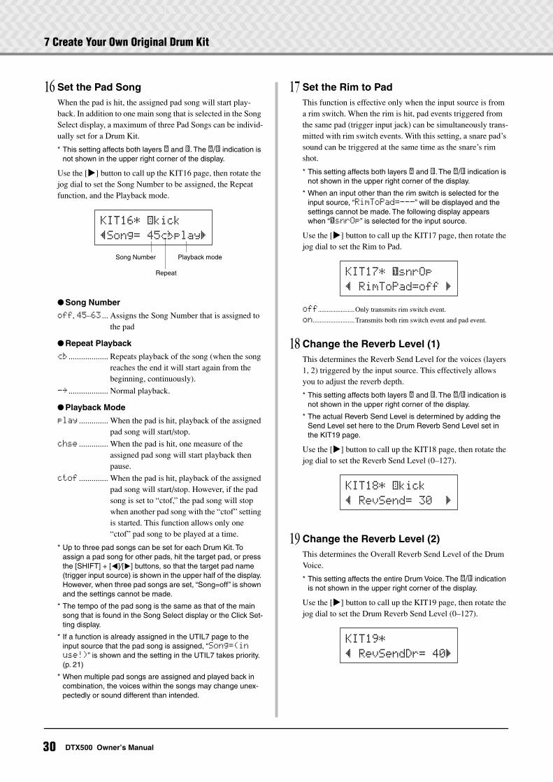
7 Create Your Own Original Drum Kit
16 Set the Pad SongWhen the pad is hit, the assigned pad song will start play-back. In addition to one main song that is selected in the Song Select display, a maximum of three Pad Songs can be individ-ually set for a Drum Kit.
* This setting affects both layers ˙ and ¶. The ˙/¶ indication is not shown in the upper right corner of the display.
Use the [>] button to call up the KIT16 page, then rotate the jog dial to set the Song Number to be assigned, the Repeat function, and the Playback mode.
Song Number
off, 45–63 ... Assigns the Song Number that is assigned to the pad
Repeat Playback
áé ................... Repeats playback of the song (when the song reaches the end it will start again from the beginning, continuously).
-≥ ................... Normal playback.
Playback Mode
play .............. When the pad is hit, playback of the assigned pad song will start/stop.
chse .............. When the pad is hit, one measure of the assigned pad song will start playback then pause.
ctof .............. When the pad is hit, playback of the assigned pad song will start/stop. However, if the pad song is set to “ctof,” the pad song will stop when another pad song with the “ctof” setting is started. This function allows only one “ctof” pad song to be played at a time.
* Up to three pad songs can be set for each Drum Kit. To assign a pad song for other pads, hit the target pad, or press the [SHIFT] + [<]/[>] buttons, so that the target pad name (trigger input source) is shown in the upper half of the display. However, when three pad songs are set, “Song=off” is shown and the settings cannot be made.
* The tempo of the pad song is the same as that of the main song that is found in the Song Select display or the Click Set-ting display.
* If a function is already assigned in the UTIL7 page to the input source that the pad song is assigned, “Song=(in use!)” is shown and the setting in the UTIL7 takes priority. (p. 21)
* When multiple pad songs are assigned and played back in combination, the voices within the songs may change unex-pectedly or sound different than intended.
17 Set the Rim to PadThis function is effective only when the input source is from a rim switch. When the rim is hit, pad events triggered from the same pad (trigger input jack) can be simultaneously trans-mitted with rim switch events. With this setting, a snare pad’s sound can be triggered at the same time as the snare’s rim shot.
* This setting affects both layers ˙ and ¶. The ˙/¶ indication is not shown in the upper right corner of the display.
* When an input other than the rim switch is selected for the input source, “RimToPad=---” will be displayed and the settings cannot be made. The following display appears when “ƒsnrOp” is selected for the input source.
Use the [>] button to call up the KIT17 page, then rotate the jog dial to set the Rim to Pad.
off.....................Only transmits rim switch event.
on........................Transmits both rim switch event and pad event.
18 Change the Reverb Level (1)This determines the Reverb Send Level for the voices (layers 1, 2) triggered by the input source. This effectively allows you to adjust the reverb depth.
* This setting affects both layers ˙ and ¶. The ˙/¶ indication is not shown in the upper right corner of the display.
* The actual Reverb Send Level is determined by adding the Send Level set here to the Drum Reverb Send Level set in the KIT19 page.
Use the [>] button to call up the KIT18 page, then rotate the jog dial to set the Reverb Send Level (0–127).
19 Change the Reverb Level (2)This determines the Overall Reverb Send Level of the Drum Voice.
* This setting affects the entire Drum Voice. The ˙/¶ indication is not shown in the upper right corner of the display.
Use the [>] button to call up the KIT19 page, then rotate the jog dial to set the Drum Reverb Send Level (0–127).
KIT16*~äkick
”Song=~45áéplay‚
Song Number
Repeat
Playback mode
KIT17*~ƒsnrOp
”~RimToPad=off~‚
KIT18*~äkick
”~RevSend=~30~~‚
KIT19*
”~RevSendDr=~40‚
30 DTX500 Owner’s Manual
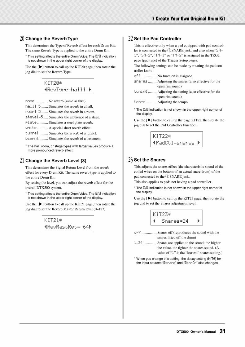
7 Create Your Own Original Drum Kit
20 Change the Reverb TypeThis determines the Type of Reverb effect for each Drum Kit. The same Reverb Type is applied to the entire Drum Kit.
* This setting affects the entire Drum Voice. The ˙/¶ indication is not shown in the upper right corner of the display.
Use the [>] button to call up the KIT20 page, then rotate the jog dial to set the Reverb Type.
none .............. No reverb (same as thru).
hall1–5 ....... Simulates the reverb in a hall.
room1–5 ....... Simulates the reverb in a room.
stage1–5 ..... Simulates the ambience of a stage.
plate............ Simulates a steel plate reverb.
white............ A special short reverb effect.
tunnel ......... Simulates the reverb of a tunnel.
bsemnt ......... Simulates the reverb of a basement.
* The hall, room, or stage types with larger values produce a more pronounced reverb effect.
21 Change the Reverb Level (3)This determines the Signal Return Level from the reverb effect for every Drum Kit. The same reverb type is applied to the entire Drum Kit.
By setting the level, you can adjust the reverb effect for the overall DTX500 system.
* This setting affects the entire Drum Voice. The ˙/¶ indication is not shown in the upper right corner of the display.
Use the [>] button to call up the KIT21 page, then rotate the jog dial to set the Reverb Master Return level (0–127).
22 Set the Pad ControllerThis is effective only when a pad equipped with pad control-ler is connected to the 1SNARE jack, and also when “SN-1”, “SN-2”, “TM-1” or “TM-2” is assigned in the TRG2 page (pad type) of the Trigger Setup pages.
The following settings can be made by rotating the pad con-troller knob.
off .................No function is assigned.
snares ..........Adjusting the snares (also effective for the open rim sound)
tuning ..........Adjusting the tuning (also effective for the open rim sound)
tempo.............Adjusting the tempo
* The ˙/¶ indication is not shown in the upper right corner of the display.
Use the [>] button to call up the page KIT22, then rotate the jog dial to set the Pad Controller function.
23 Set the SnaresThis adjusts the snares effect (the characteristic sound of the coiled wires on the bottom of an actual snare drum) of the pad connected to the 1SNARE jack.
This also applies to pads not having a pad controller.
* The ˙/¶ indication is not shown in the upper right corner of the display.
Use the [>] button to call up the KIT23 page, then rotate the jog dial to set the Snares adjustment level.
off .................Snares off (reproduces the sound with the snares lifted off the drum)
1–24 ...............Snares are applied to the sound; the higher the value, the tighter the snares sound. (A value of “1” is the “loosest” snares setting.)
* When you change this setting, the decay setting (KIT6) for the input sources “ƒsnare” and “ƒsnrOp” also changes.
KIT20*
”RevType=hall1~‚
KIT21*
”RevMastRet=~64‚
KIT22*
”PadCtl=snares~‚
KIT23*
”~~Snares=24~~~‚
31DTX500 Owner’s Manual
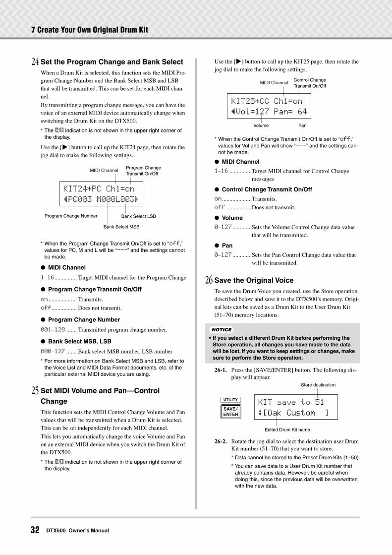
7 Create Your Own Original Drum Kit
24 Set the Program Change and Bank SelectWhen a Drum Kit is selected, this function sets the MIDI Pro-gram Change Number and the Bank Select MSB and LSB that will be transmitted. This can be set for each MIDI chan-nel.
By transmitting a program change message, you can have the voice of an external MIDI device automatically change when switching the Drum Kit on the DTX500.
* The ˙/¶ indication is not shown in the upper right corner of the display.
Use the [>] button to call up the KIT24 page, then rotate the jog dial to make the following settings.
* When the Program Change Transmit On/Off is set to “off,” values for PC, M and L will be “---” and the settings cannot be made.
MIDI Channel
1–16............... Target MIDI channel for the Program Change
Program Change Transmit On/Off
on ................... Transmits.
off................. Does not transmit.
Program Change Number
001–128 ....... Transmitted program change number.
Bank Select MSB, LSB
000–127 ....... Bank select MSB number, LSB number
* For more information on Bank Select MSB and LSB, refer to the Voice List and MIDI Data Format documents, etc. of the particular external MIDI device you are using.
25 Set MIDI Volume and Pan—Control ChangeThis function sets the MIDI Control Change Volume and Pan values that will be transmitted when a Drum Kit is selected. This can be set independently for each MIDI channel.
This lets you automatically change the voice Volume and Pan on an external MIDI device when you switch the Drum Kit of the DTX500.
* The ˙/¶ indication is not shown in the upper right corner of the display.
Use the [>] button to call up the KIT25 page, then rotate the jog dial to make the following settings.
* When the Control Change Transmit On/Off is set to “off,” values for Vol and Pan will show “---” and the settings can-not be made.
MIDI Channel
1–16 ...............Target MIDI channel for Control Change messages
Control Change Transmit On/Off
on ....................Transmits.
off .................Does not transmit.
Volume
0–127 .............Sets the Volume Control Change data value that will be transmitted.
Pan
0–127 .............Sets the Pan Control Change data value that will be transmitted.
26 Save the Original VoiceTo save the Drum Voice you created, use the Store operation described below and save it to the DTX500’s memory. Origi-nal kits can be saved as a Drum Kit to the User Drum Kit (51–70) memory locations.
26-1. Press the [SAVE/ENTER] button. The following dis-play will appear.
26-2. Rotate the jog dial to select the destination user Drum Kit number (51–70) that you want to store.
* Data cannot be stored to the Preset Drum Kits (1–50).
* You can save data to a User Drum Kit number that already contains data. However, be careful when doing this, since the previous data will be overwritten with the new data.
KIT24*PC~Ch1=on
”PC003~M000L003‚
Program Change Number
Bank Select MSB
Program Change Transmit On/Off
MIDI Channel
Bank Select LSB
• If you select a different Drum Kit before performing the Store operation, all changes you have made to the data will be lost. If you want to keep settings or changes, make sure to perform the Store operation.
KIT25*CC~Ch1=on
”Vol=127~Pan=~64
Control Change Transmit On/Off
MIDI Channel
Volume Pan
NOTICE
Edited Drum Kit name
KIT~save~to~51
:[Oak~Custom~~]
Store destination
32 DTX500 Owner’s Manual
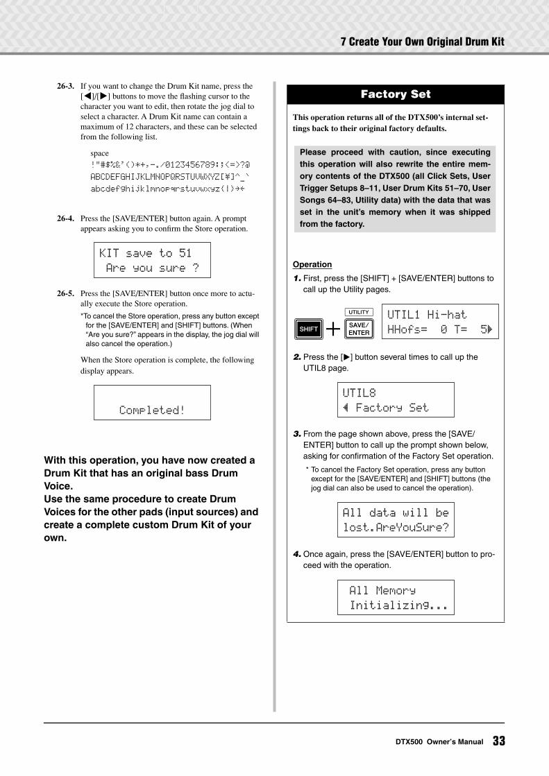
7 Create Your Own Original Drum Kit
26-3. If you want to change the Drum Kit name, press the [<]/[>] buttons to move the flashing cursor to the character you want to edit, then rotate the jog dial to select a character. A Drum Kit name can contain a maximum of 12 characters, and these can be selected from the following list.
26-4. Press the [SAVE/ENTER] button again. A prompt appears asking you to confirm the Store operation.
26-5. Press the [SAVE/ENTER] button once more to actu-ally execute the Store operation.
*To cancel the Store operation, press any button except for the [SAVE/ENTER] and [SHIFT] buttons. (When “Are you sure?” appears in the display, the jog dial will also cancel the operation.)
When the Store operation is complete, the following display appears.
With this operation, you have now created a Drum Kit that has an original bass Drum Voice.Use the same procedure to create Drum Voices for the other pads (input sources) and create a complete custom Drum Kit of your own.
space
!"#$%&'()*+,-./0123456789:;<=>?@
ABCDEFGHIJKLMNOPQRSTUVWXYZ[\]^_`
abcdefghijklmnopqrstuvwxyz|≥≤
KIT~save~to~51
~Are~you~sure~?
~~~Completed!
Factory Set
This operation returns all of the DTX500’s internal set-tings back to their original factory defaults.
Operation
1. First, press the [SHIFT] + [SAVE/ENTER] buttons to call up the Utility pages.
2. Press the [>] button several times to call up the UTIL8 page.
3. From the page shown above, press the [SAVE/ENTER] button to call up the prompt shown below, asking for confirmation of the Factory Set operation.
* To cancel the Factory Set operation, press any button except for the [SAVE/ENTER] and [SHIFT] buttons (the jog dial can also be used to cancel the operation).
4. Once again, press the [SAVE/ENTER] button to pro-ceed with the operation.
Please proceed with caution, since executingthis operation will also rewrite the entire mem-ory contents of the DTX500 (all Click Sets, UserTrigger Setups 8–11, User Drum Kits 51–70, UserSongs 64–83, Utility data) with the data that wasset in the unit’s memory when it was shippedfrom the factory.
UTIL1~Hi-hat
HHofs=~~0~T=~~5‚
UTIL8
”~Factory~Set
All~data~will~be
lost.AreYouSure?
~All~Memory
~Initializing...
33DTX500 Owner’s Manual
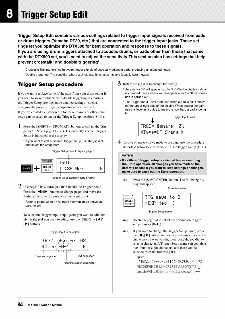
8 Trigger Setup Edit
Trigger Setup Edit contains various settings related to trigger input signals received from pads or drum triggers (Yamaha DT20, etc.) that are connected to the trigger input jacks. These set-tings let you optimize the DTX500 for best operation and response to these signals.If you are using drum triggers attached to acoustic drums, or pads other than those that came with the DTX500 set, you’ll need to adjust the sensitivity. This section also has settings that help prevent crosstalk* and double triggering*.
* Crosstalk: The interference between trigger signals of physically adjacent pads, producing unexpected notes.
* Double triggering: The condition where a single pad hit causes multiple (usually two) triggers.
Trigger Setup procedure
If you want to replace some of the pads from your drum set, or if you need to solve problems with double triggering or crosstalk, the Trigger Setup provides more detailed settings—such as changing the preset’s trigger setup—for individual pads.
If you’ve created a custom setup for these reasons or others, that setup can be saved to one of the Trigger Setup locations (8–11).
1 Press the [SHIFT] + [DRUM KIT] buttons to call up the Trig-ger Setup Select page (TRG1). The currently selected Trigger Setup is indicated in the display.
* If you want to edit a different trigger setup, use the jog dial and select the setup here.
2 Use pages TRG2 through TRG8 to edit the Trigger Setup.
Press the [<]/[>] buttons to change pages and move the flashing cursor to the parameter you want to set.
* Refer to pages 35 to 37 for more information on individual parameters.
To select the Trigger Input (input jack) you want to edit, sim-ply hit the pad you want to edit or use the [SHIFT] + [<]/[>] buttons.
3 Rotate the jog dial to change the setting.
* An asterisk “*” will appear next to “TRG” in the display if data is changed. This asterisk will disappear after the Store opera-tion is carried out.
* The Trigger Input Level produced when a pad is hit is shown on the upper right side of the display. When setting the gain, use this level as a guide to measure how hard a pad is being hit.
4 To save changes you’ve made to the data, use the procedure described below to store them to a User Trigger Setup (8–11).
4-1. Press the [SAVE/ENTER] button. The following dis-play will appear.
4-2. Rotate the jog dial to select the destination trigger setup number (8–11).
4-3. If you want to change the Trigger Setup name, press the [<]/[>] buttons to move the flashing cursor to the character you want to edit, then rotate the jog dial to select a character. A Trigger Setup name can contain a maximum of eight characters, and these can be selected from the following list.
Trigger Setup Select display (page 1)
Trigger Setup Number: Setup Name
TRG1~~~ååååååååå
1~:XP~Med~~~~~~‚
Trigger Input to be edited
Next page iconPrevious page icon
Flashing cursor (parameter)
TRG2~ ƒsnare~~0%
”Type=SN-1~~~~~‚
• If a different trigger setup is selected before executing the Store operation, all changes you have made to the data will be lost. If you want to keep settings or changes, make sure to carry out the Store operation.
Trigger Input Level
TRG2* ƒsnare~~0%
”Type=DT~Snare~‚
NOTICE
Trigger Setup name
TRG~save~to~8
:[XP~Med~~]
Store destination
space
!"#$%&'()*+,-./0123456789:;<=>?@
ABCDEFGHIJKLMNOPQRSTUVWXYZ[\]^_`
abcdefghijklmnopqrstuvwxyz|≥≤
34 DTX500 Owner’s Manual
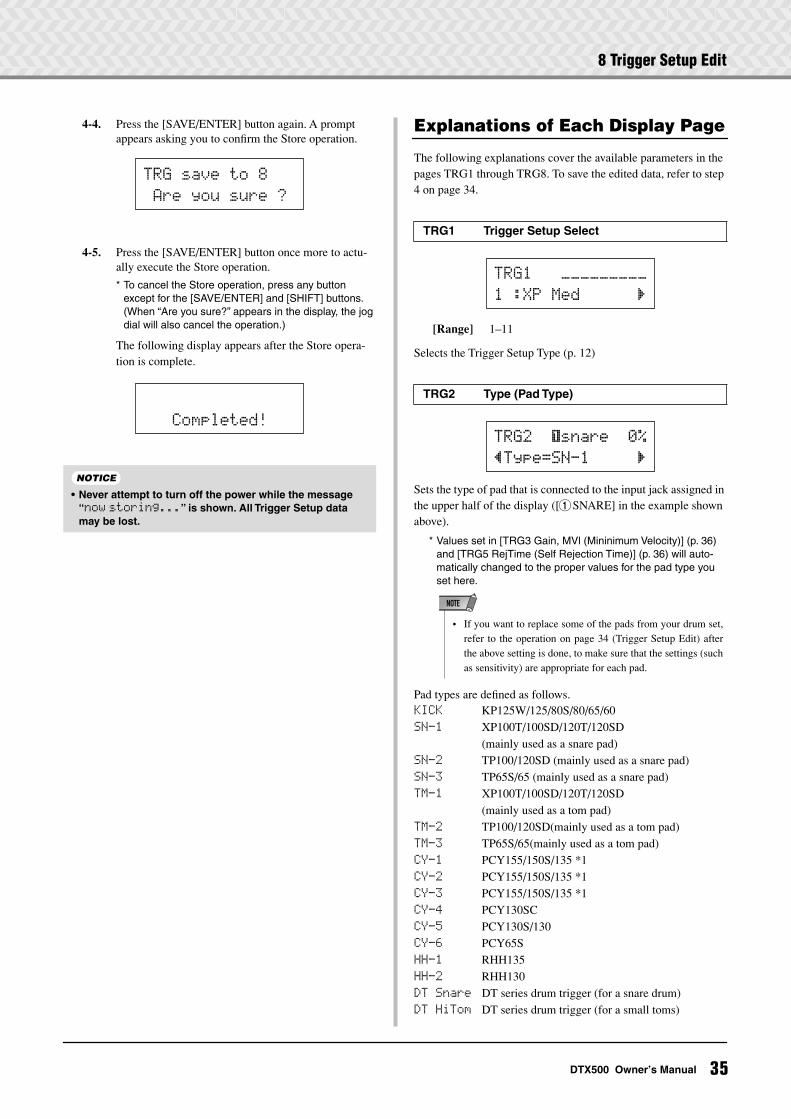
8 Trigger Setup Edit
4-4. Press the [SAVE/ENTER] button again. A prompt appears asking you to confirm the Store operation.
4-5. Press the [SAVE/ENTER] button once more to actu-ally execute the Store operation.
* To cancel the Store operation, press any button except for the [SAVE/ENTER] and [SHIFT] buttons. (When “Are you sure?” appears in the display, the jog dial will also cancel the operation.)
The following display appears after the Store opera-tion is complete.
Explanations of Each Display Page
The following explanations cover the available parameters in the pages TRG1 through TRG8. To save the edited data, refer to step 4 on page 34.
[Range] 1–11
Selects the Trigger Setup Type (p. 12)
Sets the type of pad that is connected to the input jack assigned in the upper half of the display ([1SNARE] in the example shown above).
* Values set in [TRG3 Gain, MVl (Mininimum Velocity)] (p. 36) and [TRG5 RejTime (Self Rejection Time)] (p. 36) will auto-matically changed to the proper values for the pad type you set here.
Pad types are defined as follows.KICK KP125W/125/80S/80/65/60SN-1 XP100T/100SD/120T/120SD
(mainly used as a snare pad)SN-2 TP100/120SD (mainly used as a snare pad)SN-3 TP65S/65 (mainly used as a snare pad)TM-1 XP100T/100SD/120T/120SD
(mainly used as a tom pad)TM-2 TP100/120SD(mainly used as a tom pad)TM-3 TP65S/65(mainly used as a tom pad)CY-1 PCY155/150S/135 *1CY-2 PCY155/150S/135 *1CY-3 PCY155/150S/135 *1CY-4 PCY130SCCY-5 PCY130S/130CY-6 PCY65SHH-1 RHH135HH-2 RHH130DT Snare DT series drum trigger (for a snare drum)DT HiTom DT series drum trigger (for a small toms)
• Never attempt to turn off the power while the message “now storing...” is shown. All Trigger Setup data may be lost.
TRG~save~to~8
~Are~you~sure~?
~~~Completed!
NOTICE
TRG1 Trigger Setup Select
TRG2 Type (Pad Type)
TRG1~~~ååååååååå
1~:XP~Med~~~~~~‚
TRG2~ ƒsnare~~0%
”Type=SN-1~~~~~‚
• If you want to replace some of the pads from your drum set,refer to the operation on page 34 (Trigger Setup Edit) afterthe above setting is done, to make sure that the settings (suchas sensitivity) are appropriate for each pad.
NOTE
35DTX500 Owner’s Manual
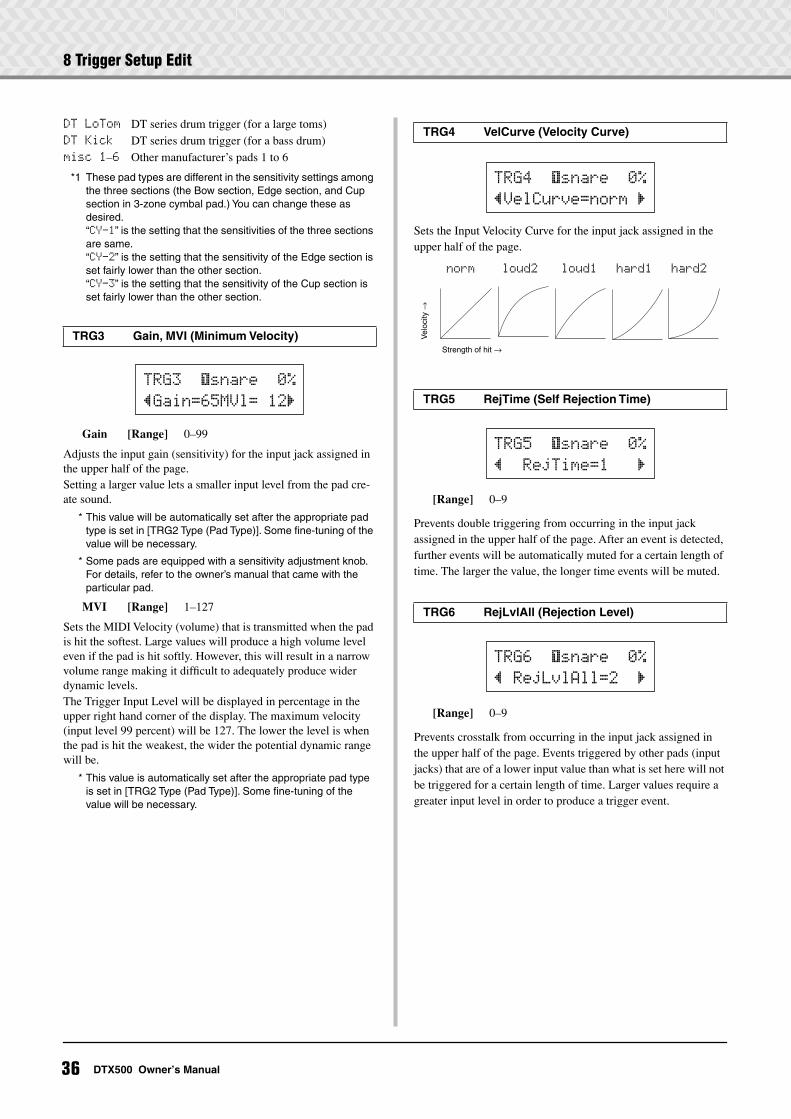
8 Trigger Setup Edit
DT LoTom DT series drum trigger (for a large toms)DT Kick DT series drum trigger (for a bass drum)misc~1–6 Other manufacturer’s pads 1 to 6
*1 These pad types are different in the sensitivity settings among the three sections (the Bow section, Edge section, and Cup section in 3-zone cymbal pad.) You can change these as desired.“CY-1” is the setting that the sensitivities of the three sections are same.“CY-2” is the setting that the sensitivity of the Edge section is set fairly lower than the other section.“CY-3” is the setting that the sensitivity of the Cup section is set fairly lower than the other section.
Gain [Range] 0–99
Adjusts the input gain (sensitivity) for the input jack assigned in the upper half of the page.Setting a larger value lets a smaller input level from the pad cre-ate sound.
* This value will be automatically set after the appropriate pad type is set in [TRG2 Type (Pad Type)]. Some fine-tuning of the value will be necessary.
* Some pads are equipped with a sensitivity adjustment knob. For details, refer to the owner’s manual that came with the particular pad.
MVI [Range] 1–127
Sets the MIDI Velocity (volume) that is transmitted when the pad is hit the softest. Large values will produce a high volume level even if the pad is hit softly. However, this will result in a narrow volume range making it difficult to adequately produce wider dynamic levels.The Trigger Input Level will be displayed in percentage in the upper right hand corner of the display. The maximum velocity (input level 99 percent) will be 127. The lower the level is when the pad is hit the weakest, the wider the potential dynamic range will be.
* This value is automatically set after the appropriate pad type is set in [TRG2 Type (Pad Type)]. Some fine-tuning of the value will be necessary.
Sets the Input Velocity Curve for the input jack assigned in the upper half of the page.
[Range] 0–9
Prevents double triggering from occurring in the input jack assigned in the upper half of the page. After an event is detected, further events will be automatically muted for a certain length of time. The larger the value, the longer time events will be muted.
[Range] 0–9
Prevents crosstalk from occurring in the input jack assigned in the upper half of the page. Events triggered by other pads (input jacks) that are of a lower input value than what is set here will not be triggered for a certain length of time. Larger values require a greater input level in order to produce a trigger event.
TRG3 Gain, MVI (Minimum Velocity)
TRG3~ ƒsnare~~0%
”Gain=65MVl=~12‚
TRG4 VelCurve (Velocity Curve)
TRG5 RejTime (Self Rejection Time)
TRG6 RejLvlAll (Rejection Level)
TRG4~ ƒsnare~~0%
”VelCurve=norm~‚
norm loud2 loud1 hard1 hard2
Vel
ocity
→
Strength of hit →
TRG5 ~ƒsnare~~0%
”~~RejTime=1~~~‚
TRG6 ~ƒsnare~~0%
”~RejLvlAll=2~~‚
36 DTX500 Owner’s Manual
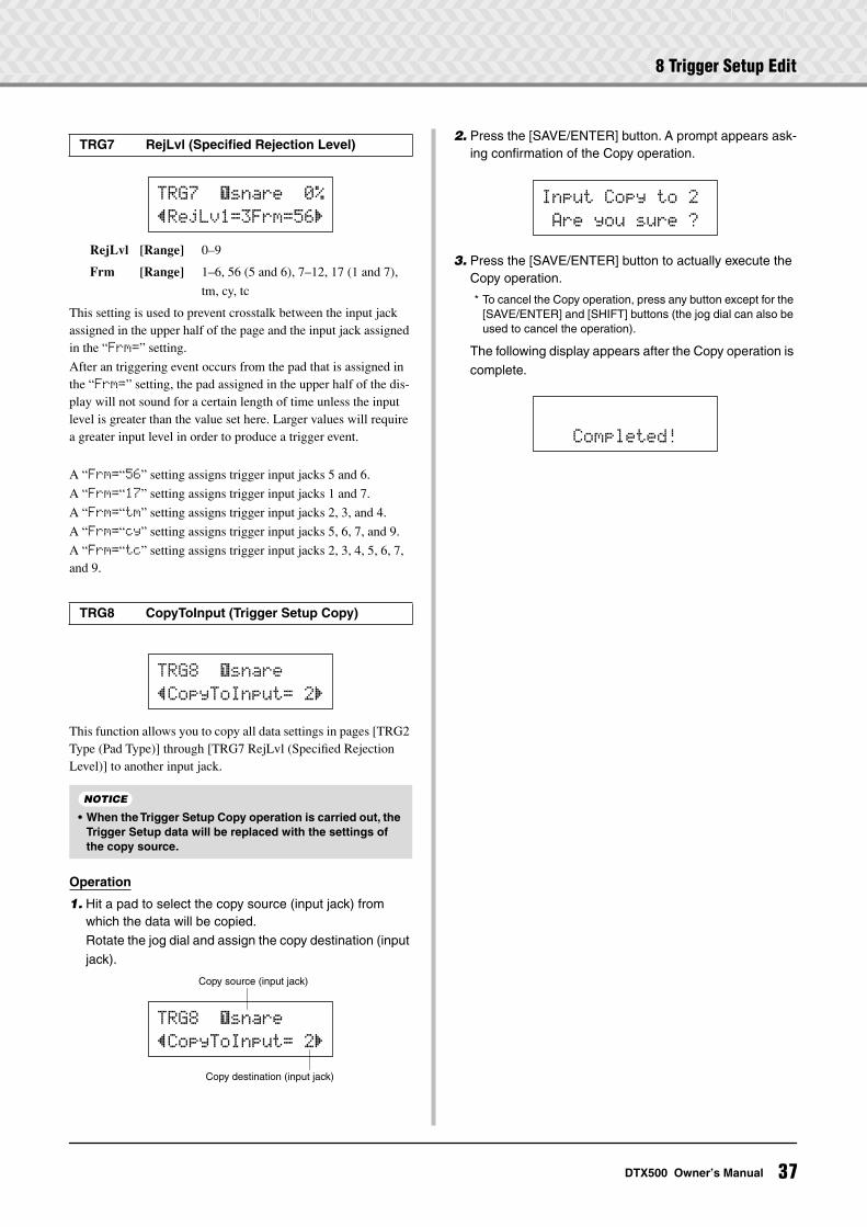
8 Trigger Setup Edit
RejLvl [Range] 0–9
Frm [Range] 1–6, 56 (5 and 6), 7–12, 17 (1 and 7),
tm, cy, tc
This setting is used to prevent crosstalk between the input jack assigned in the upper half of the page and the input jack assigned in the “Frm=” setting.
After an triggering event occurs from the pad that is assigned in the “Frm=” setting, the pad assigned in the upper half of the dis-play will not sound for a certain length of time unless the input level is greater than the value set here. Larger values will require a greater input level in order to produce a trigger event.
A “Frm=“56” setting assigns trigger input jacks 5 and 6.
A “Frm=“17” setting assigns trigger input jacks 1 and 7.
A “Frm=“tm” setting assigns trigger input jacks 2, 3, and 4.
A “Frm=“cy” setting assigns trigger input jacks 5, 6, 7, and 9.
A “Frm=“tc” setting assigns trigger input jacks 2, 3, 4, 5, 6, 7, and 9.
This function allows you to copy all data settings in pages [TRG2 Type (Pad Type)] through [TRG7 RejLvl (Specified Rejection Level)] to another input jack.
Operation
1. Hit a pad to select the copy source (input jack) from which the data will be copied.Rotate the jog dial and assign the copy destination (input jack).
2. Press the [SAVE/ENTER] button. A prompt appears ask-ing confirmation of the Copy operation.
3. Press the [SAVE/ENTER] button to actually execute the Copy operation.
* To cancel the Copy operation, press any button except for the [SAVE/ENTER] and [SHIFT] buttons (the jog dial can also be used to cancel the operation).
The following display appears after the Copy operation is complete.
TRG7 RejLvl (Specified Rejection Level)
TRG8 CopyToInput (Trigger Setup Copy)
• When the Trigger Setup Copy operation is carried out, the Trigger Setup data will be replaced with the settings of the copy source.
TRG7~ ƒsnare~~0%
”RejLv1=3Frm=56‚
TRG8 ~ƒsnare
”CopyToInput=~2‚
NOTICE
Copy source (input jack)
Copy destination (input jack)
TRG8~ ƒsnare
”CopyToInput=~2‚
Input~Copy~to~2
~Are~you~sure~?
~~~Completed!
37DTX500 Owner’s Manual
Error Messages
The DTX500 displays error messages when incorrect settings have been made or invalid opera-tions have been detected, or when any abnormal operation or malfunction occurs.If an error message appears, check the list below and make the appropriate corrections.
This message appears just after the power is switched on and the device cannot correctly read the data due to the Factory Reset operation being active.
The backup ROM data may have been damaged. Contact the nearest Yamaha Service Cen-ter or the dealer where you purchased the device.
You have exceeded the memory capacity of the user song.
Delete unused songs to make more memory available and try recording again.
Writing data to the backup ROM has failed.
TroubleshootingThe DTX500 does not produce sound, or does not rec-ognize trigger inputs. Are the pads or drum triggers (Yamaha DT20, etc.) properly
connected to the DTX500’s trigger input jacks? (p. 10)
Is the DTX500 properly connected to headphones or an exter-nal audio device such as an amplifier, speaker, etc.? (p. 10)
Check the position of the Standby/On switches and volume levels of any connected external audio devices, such as an amplifier, speaker, etc.
The volume knob on the rear panel may be turned down (p. 13).
Is the gain set too low? (p. 36 [TRG3 Gain, MVI (Minimum Velocity)])
The volume setting on the Drum Kit Select display’s “KIT3 Vol-ume” page (p. 27) may be set to “0.”
Is there a problem with the cable you are using?
The drum voices for both layers ˙ and ¶ may be set to “00:NoAssign.” (p. 27 Step2: [KIT2])
The external tone generator does not produce sound. Is the MIDI cable (connector) properly connected? (p. 11)
Is the correct MIDI connector being used? (p. 11)
Are the MIDI note number values appropriate?(p. 28 Steps 8 to 10: [KIT8], [KIT9], [KIT10])
The drum voices for both layers ˙ and ¶ may be set to “00:NoAssign.” (p. 27 Step2: [KIT2])
A voice other than the set voice is produced. Is the transmitting MIDI channel set to a channel that is not
used for the drum voice (ch=10)? (p. 28, Step 9: [KIT9])
Are two-layer voices set in the voice setting on the Drum Kit Select display? (p. 27 Step 2: [KIT2])
Produces sound but the sensitivity is too low (volume is low). Is the gain set too low? (p. 36: [TRG3 Gain, MVI (Minimum
Velocity)])
Pads with a level adjustment knob should be adjusted (increased).
Is the minimum velocity set too low? (p. 36: [TRG3 Gain, MVI (Minimum Velocity)])
Are you using a proper velocity curve? (p. 36: [TRG4 VelCurve (Velocity Curve)])
Is the volume of the voice you want to use too low? (p. 27 Step 3: [KIT3])
ERROR
Data~Initialized
ERROR
Memory~full
ERROR
Can'tWriteMemory
38 DTX500 Owner’s Manual
Troubleshooting
The trigger sound is not stable. (For acoustic drums) Check the entry “Produces sound but the sensitivity is too low
(volume is low)” above.
Try selecting a larger pad type setting (DT snare → DT HiTom → DT LoTom → DT Kick). (p. 35: [TRG2 Type (Pad Type)])
Is the Drum Trigger (Yamaha DT20, etc.) improperly attached with duct tape? (Is there any old adhesive remaining on the head?)
Is the cable securely connected to the drum trigger (Yamaha DT20, etc.) jack?
Double triggering is produced. Pads with a level adjustment knob should be adjusted (low-
ered).
Is the gain set too high? (p. 36: [TRG3 Gain, MVI (Minimum Velocity)])
Use the self-rejection setting. (p. 36: [TRG5 RejTime (Self Rejection Time)])
(KP65) Is the pad type for the input jack to which the KP65 is connected set to Kick Pad? (p. 35: [TRG2 Pad Type])
Are you using drum triggers (trigger sensors) made by other manufacturers? Too large a signal can result in double trigger-ing.
Is the head causing irregular vibrations? It may be necessary to mute the head.
When using acoustic drums, make sure the Drum Trigger is attached near the rim (above the bearing) and not near the center of the head.
When using acoustic drums, make sure that nothing is touch-ing the Drum Trigger.
Crosstalk (trigger interference from different inputs) is produced. Is the gain set too high? (p. 36: [TRG3 Gain, MVI (Minimum
Velocity)])
Try increasing the rejection parameter. However, avoid setting this value too high since that may cause the sound to not be produced when another pad (trigger input) is hit at the same time. (p. 36: [TRG6 RejLvlAll (Rejection Level)])
If crosstalk is produced with a specific trigger input, try using specific rejection. (p. 37: [TRG7 RejLvl (Specified Rejection Level)])
When using acoustic drums, place the Drum Trigger away from any nearby drum.
Sounds are cut when you play continuously. The maximum polyphony of 32 voices might be exceeded. In
the Drum Kit Select dispaly’s “KIT15 Key Assign Mode” page (p. 29), set the “KeyAssign” value to “semi” or “mono.”
When two pads (drums) are played only one sound is heard. Raise the gain setting of the pad (trigger input) that is not pro-
ducing sound. (p. 36: [TRG3 Gain, MVI (Minimum Velocity)])
Lower the rejection setting of the pad (trigger input) that is not producing sound. (p. 36: [TRG6 RejLvlAll (Rejection Level)])
Lower the specified rejection setting of the pad (trigger input) that is not producing sound (p. 37: [TRG7 RejLvl (Specified Rejection Level)])
Are both pads (trigger inputs) set to the same alternate group? (p. 29 Step 14: [KIT14])
The sound is always loud. Is the minimum velocities minimum value set too high? (p. 36:
[TRG3 Gain, MVI (Minimum Velocity)])
Are you using an appropriate velocity curve? (p. 36: [TRG4 VelCurve (Velocity Curve)])
Are you using a pad made by another manufacturer? Depend-ing upon the manufacturer, output levels might be too large.
The DTX500 does not receive any switch or trigger sig-nals. If you can access the Utility display, perform the Factory Set
operation. The DTX500 will reset to its factory settings. (p. 33: [UTIL8 Factory Set])
Turn the power off then on while holding the [<] and [>] but-tons together. The DTX500 will reset to its factory settings.
The sound does not stop. Some voices have very long release times when the “key off”
parameter is set to “disable.” (p. 28 Step 11: [KIT11]) Press the [DRUM KIT] button to temporarily stop the sound.
The pad controller function does not work Have you connected a pad equipped with a pad controller,
such as the TP100 or TP120SD?
Are the pad controller settings properly set? (p. 15)
The Closed Hi-Hat voice is not produced. Is the proper pad type selected? If the RHH135/130 is used as
a hi-hat controller, the pad type must be set to “RHH.” (p. 35: [TRG2 Pad Type])
The edge or cup sections of the cymbal pad do not pro-duce sound when struck. The choke functions do not work. Is the proper pad type selected? Select the appropriate pad
type for the kind of cymbal pad you are using. (p. 35: [TRG2 Pad Type])
The sound produced by the edge and cup section will not be produced when a pad equipped with a rim switch (PCY135/155 etc.) is connected to the Input jack 9– @.
Foot Splashes are not produced. Is the foot controller connected to the HI HAT CONTROL jack?
Adjust the detection time of foot splashes. (p. 14: Adjusting the Hi-hat)
I need to restore the original factory settings of the instrument. Use the Factory Set function (p. 33) to reset the DTX500 inter-
nal settings to the initial factory settings.
39DTX500 Owner’s Manual
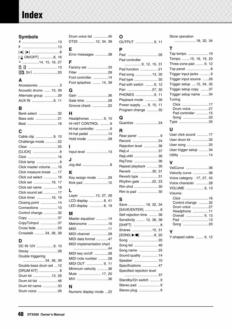
40 DTX500 Owner’s Manual
Symbols” .................................... 13‚ .................................... 13[<], [>] ............................ 8[ ON/OFF] ..............8, 16 *
.................14, 15, 16, 27
˙
,
.............................. 13
˚¡
,
∞¢
......................... 20
A
Accessories ..................... 3Acoustic drums .......10, 39Alternate group ............. 29AUX IN ......................9, 11
B
Bank select ................... 32Bass solo ...................... 21Beat ............................... 16
C
Cable clip ..................9, 10Challenge mode ............ 22Clear ............................. 25[CLICK] ........................... 8Click .............................. 16Click lamp ....................... 8Click master volume ...... 16Click measure break ..... 17Click out select .............. 18Click set ..................16, 17Click set name .............. 18Click sound set .............. 17Click timer ...............16, 19Closing point ................. 14Connections .................. 10Control change .............. 32Copy .............................. 37CopyToInput ................. 37Cross fade ..................... 29Crosstalk .......... 34, 36, 39
D
DC IN 12V .................9, 10Decay ............................ 28Double triggering
...................... 34, 36, 39Double-bass drum set ... 12[DRUM KIT] ..................... 8Drum kit ...................13, 26Drum kit list ................... 46Drum kit name ............... 33Drum voice .................... 26
Drum voice list ...............45DT20 .................12, 34, 39
E
Error messages .............38
F
Factory set .....................33Filter ..............................28Foot controller ...............14Foot splashes ......... 14, 39
G
Gain ...............................36Gate time .......................28Groove check ................22
H
Headphones ............. 9, 10HI HAT CONTROL ..........9Hi-hat controller ...............9Hi-hat pedal ...................14Hold mode .....................28
I
Input level ......................13
J
Jog dial ............................8
K
Key assign mode ...........29Kick pad .........................12
L
Layer ................13, 27, 29LCD display .............. 8, 41LED display .............. 8, 19
M
Master equalizer ............14Metronome ....................16MIDI ...............................11MIDI channel .................28MIDI data format ............47MIDI implementation chart
...................................44MIDI key on/off ..............28MIDI note number ..........28MIDI OUT ................. 9, 11Minimum velocity ...........36Mute ....................... 17, 20MVI ................................36
N
Numeric display mode ...22
O
OUTPUT ...................9, 11
P
Pad ............................... 26Pad controller
.................9, 12, 15, 31Pad function .................. 21Pad song .................13, 30Pad type ........................ 35Pad with switch .........9, 12Pan .........................27, 32PHONES ...................9, 11Playback mode ............. 30Power supply ..... 9, 10, 11Program change ........... 32
Q
Quantize ....................... 24
R
Rear panel ...................... 9Record .......................... 24Rejection level .............. 36RejLvl ............................ 37RejLvlAll ........................ 36RejTime ........................ 36Repeat playback ........... 30Reverb ....................30, 31Reverb type .................. 31Rhythm gate ...........22, 23Rim shot ........................ 30Rim to pad .................... 30
S
Save ................. 18, 32, 34[SAVE/ENTER] ............... 8Self rejection time ......... 36Sensitivity ......... 12, 36, 38[SHIFT] ........................... 8Snares ....................15, 31[SONG
>
/
] .............8, 20
Song ............................. 20Song list ........................ 46Song name ................... 25Sound quality ................ 14Speaker ........................ 10Specifications ................ 47Specified rejection level
.................................. 37Standby/On switch .......... 9Stereo pad ...................... 9Stereo plug ..................... 9
Store operation......................18, 32, 34
T
Tap tempo .....................19Tempo ........15, 16, 19, 20Three-zone pad ........ 9, 12Top panel ........................8Trigger input jacks ...........9Trigger input source ......26Trigger setup ....12, 34, 35Trigger setup copy ........37Trigger setup name .......34Tuning
Click ...........................17Drum voice .................27Pad controller .............15Song ..........................20
Type ..............................35
U
User click sound ............17User drum kit .................32User song ......................25User trigger setup ..........34Utility .............................14
V
VelCurve .......................36Velocity curve ................36Voice category .17, 27, 45Voice character .............28VOLUME .................. 9, 13Volume
Click ...........................16Control change ..........32Drum voice .................27Headphone ................11Overall .................. 9, 13Pad ............................13Song ..........................20
Y
Y-shaped cable ........ 9, 12
Index
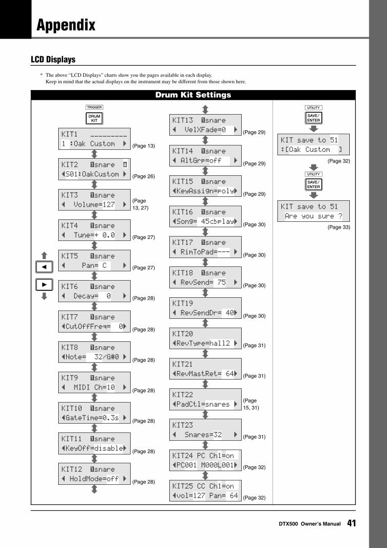
Appendix
LCD Displays
* The above “LCD Displays” charts show you the pages available in each display. Keep in mind that the actual displays on the instrument may be different from those shown here.
Drum Kit Settings
KIT1 ååååååååå
1 :Oak Custom ‚
KIT2 ƒsnare ˙
”S01:OakCustom ‚
KIT3 ƒsnare
” Volume=127 ‚
KIT4 ƒsnare
” Tune=+ 0.0 ‚
KIT5 ƒsnare
” Pan= C ‚
KIT6 ƒsnare
” Decay= 0 ‚
KIT7 ƒsnare
”CutOffFreq= 0‚
KIT8 ƒsnare
”Note= 32/G#0 ‚
KIT9 ƒsnare
” MIDI Ch=10 ‚
KIT10 ƒsnare
”GateTime=0.3s ‚
KIT11 ƒsnare
”KeyOff=disable‚
KIT12 ƒsnare
” HoldMode=off ‚
(Page 13)
(Page 26)
(Page 13, 27)
(Page 27)
(Page 27)
(Page 28)
(Page 28)
(Page 28)
(Page 28)
(Page 28)
(Page 28)
(Page 28)
KIT14 ƒsnare
” AltGrp=off ‚
KIT15 ƒsnare
”KeyAssign=poly‚
KIT13 ƒsnare
” VelXFade=0 ‚
KIT16 ƒsnare
”Song= 45áéplay‚
KIT17 ƒsnare
” RimToPad=--- ‚
KIT18 ƒsnare
” RevSend= 75 ‚
KIT23
” Snares=32 ‚
KIT24 PC Ch1=on
”PC001 M000L001‚
KIT25 CC Ch1=on
”vol=127 Pan= 64
KIT19
” RevSendDr= 40‚
KIT20
”RevType=hall2 ‚
KIT21
”RevMastRet= 64‚
KIT22
”PadCtl=snares ‚
(Page 29)
(Page 29)
(Page 30)
(Page 30)
(Page 30)
(Page 30)
(Page 31)
(Page 31)
(Page 15, 31)
(Page 31)
(Page 32)
(Page 32)
(Page 29)
KIT save to 51
:[Oak Custom ]
KIT save to 51
Are you sure ?
(Page 32)
(Page 33)
41DTX500 Owner’s Manual
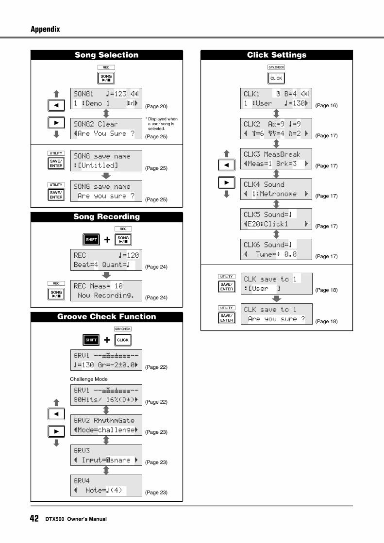
Appendix
Song Selection
Song Recording
Groove Check Function
SONG1 ⁄=123 ÷›
1 :Demo 1 ∞¢‚
SONG2 Clear
”Are You Sure ?
(Page 20)
(Page 25)
* Displayed when a user song is selected.
(Page 25)
(Page 25)
SONG save name
:[Untitled]
SONG save name
Are you sure ?
REC ⁄=120
Beat=4 Quant=⁄
REC Meas= 10
Now Recording.
(Page 24)
(Page 24)
GRV1 --æ√æ’æææ--
⁄=130 Gr=-2œ0.0‚
GRV2 RhythmGate
”Mode=challenge‚
GRV3
” Input=ƒsnare ‚
GRV4
” Note=⁄(4)
GRV1 --æ√æ’æææ--
80Hits/ 16%(DÀ)‚
(Page 22)
(Page 22)
(Page 23)
(Page 23)
(Page 23)
Challenge Mode
Click Settings
CLK1 ∫ B=4 ÷›
1 :User ⁄=130‚
CLK2 A˘=9 ¤=9
” ‹=6 ßß=4 Œ=2 ‚
CLK3 MeasBreak
”Meas=1 Brk=3 ‚
CLK4 Sound
” 1:Metronome ‚
CLK5 Sound=¤
”E20:Click1 ‚
CLK6 Sound=¤
” Tune=+ 0.0
(Page 16)
(Page 17)
(Page 17)
(Page 17)
(Page 17)
(Page 17)
CLK save to 1
:[User ]
CLK save to 1
Are you sure ?
(Page 18)
(Page 18)
42 DTX500 Owner’s Manual
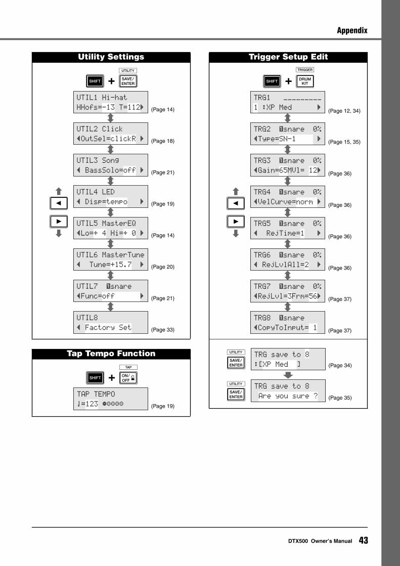
Appendix
Utility Settings
Tap Tempo Function
UTIL1 Hi-hat
HHofs=-13 T=112‚
UTIL2 Click
”OutSel=clickR ‚
UTIL3 Song
” BassSolo=off ‚
UTIL4 LED
” Disp=tempo ‚
UTIL5 MasterEQ
”Lo=+ 4 Hi=+ 0 ‚
UTIL6 MasterTune
” Tune=+15.7 ‚
UTIL7 ƒsnare
”Func=off ‚
UTIL8
” Factory Set
(Page 14)
(Page 18)
(Page 21)
(Page 19)
(Page 14)
(Page 20)
(Page 21)
(Page 33)
TAP TEMPO
¤=123 ≠ªªªª (Page 19)
Trigger Setup Edit
TRG1 ååååååååå
1 :XP Med ‚
TRG2 ƒsnare 0%
”Type=SN-1 ‚
TRG3 ƒsnare 0%
”Gain=65MVl= 12‚
TRG4 ƒsnare 0%
”VelCurve=norm ‚
TRG5 ƒsnare 0%
” RejTime=1 ‚
TRG6 ƒsnare 0%
” RejLvlAll=2 ‚
TRG7 ƒsnare 0%
”RejLvl=3Frm=56‚
TRG8 ƒsnare
”CopyToInput= 1
(Page 12, 34)
(Page 15, 35)
(Page 36)
(Page 36)
(Page 36)
(Page 36)
(Page 37)
(Page 37)
TRG save to 8
:[XP Med ]
TRG save to 8
Are you sure ?
(Page 34)
(Page 35)
43DTX500 Owner’s Manual
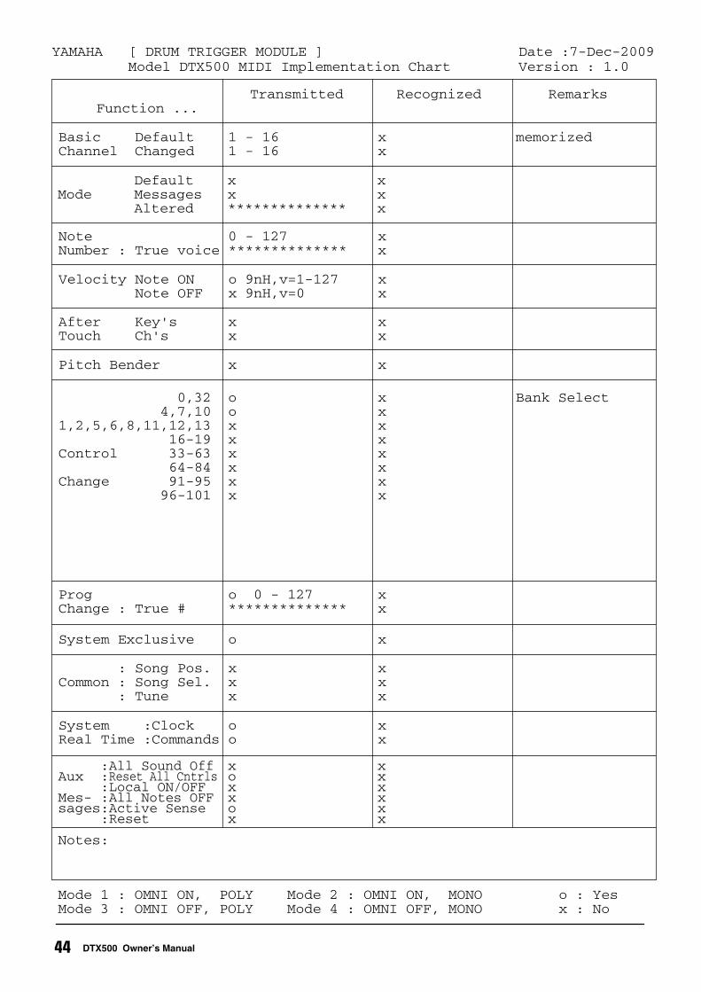
Transmitted Recognized Remarks Function ...
Mode 1 : OMNI ON, POLY Mode 2 : OMNI ON, MONO o : YesMode 3 : OMNI OFF, POLY Mode 4 : OMNI OFF, MONO x : No
Notes:
:All Sound Off x x Aux :Reset All Cntrls o x :Local ON/OFF x xMes- :All Notes OFF x xsages:Active Sense o x :Reset x x
System :Clock o xReal Time :Commands o x
: Song Pos. x xCommon : Song Sel. x x : Tune x x
System Exclusive o x
Prog o 0 - 127 xChange : True # ************** x
0,32 o x Bank Select 4,7,10 o x1,2,5,6,8,11,12,13 x x 16-19 x xControl 33-63 x x 64-84 x x Change 91-95 x x 96-101 x x
Pitch Bender x x
After Key's x xTouch Ch's x x
Velocity Note ON o 9nH,v=1-127 x Note OFF x 9nH,v=0 x
Note 0 - 127 xNumber : True voice ************** x
Default x xMode Messages x x Altered ************** x
Basic Default 1 - 16 x memorizedChannel Changed 1 - 16 x
YAMAHA [ DRUM TRIGGER MODULE ] Date :7-Dec-2009Model DTX500 MIDI Implementation Chart Version : 1.0
44 DTX500 Owner’s Manual
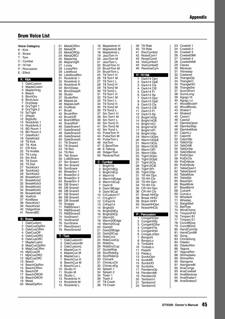
Appendix
Drum Voice List
Voice CategoryK : KickS : SnareT : TomC : CymbalH : Hi-hatP : PercussionE : Effect
1 OakCustom 2 MapleCustm3 MapleVintg4 Beech5 BirchDry6 BirchJazz7 DryDeep8 DryTight 19 DryTight 2
10 SoTight11 2Head12 BigSofty13 RockAmb 114 RockAmb 215 BD Room 116 BD Room 217 GateKick118 GateKick219 T8 Kick20 T9 Kick21 CR Kick22 T9 HrdAtk23 T9 Long24 Sm Kick25 T8 Down26 T9 Dist27 TechKick128 TechKick229 TechKick330 BreakKick131 BreakKick232 BreakKick333 BreakKick434 BreakKick535 BreakKick636 VoxKick37 KickBass38 ResoKick139 ResoKick240 DidgerKick41 ReversBD
1 OakCustom2 OakCusOpRm3 OakCusClRm4 OakCusOff5 OakCusOffO6 OakCusOffC7 MapleCustm8 MapCusOpRm9 MapCusClRm
10 MplCusOff11 MplCusOffO12 MplCusOffC13 Beech14 BeechOpRim15 BeechClRim16 BeechOff17 BeechOffOR18 BeechOffCR19 Metal20 MetalOpRim
21 MetalClRim22 MetalOff23 MetalOffOp24 MetalOffCl25 MapleVtg26 MapleVtgR27 Loosy28 LoosyRim29 LiteWood30 LiteWoodRm31 RockAmb 132 RockAmb 233 RockAmb R34 BirchDeep35 BirchDeepR36 Studio37 StudioRim38 MapleLite39 MapleLiteR40 DryMute41 Brush42 BrushRim43 BrushOff44 BrshOffRim45 SnareRoll*46 GateSnare147 GateSnare248 GateSnare349 GateSnare450 GateSnare551 T8 Snare152 T8 Snare253 T8 Rim54 T9 Rim55 Tek Snare56 LoBitSnare57 Sm Snare158 Sm Snare259 SynSnare60 BreakSnr 161 BreakSnr 262 BreakSnr 363 BreakSnr 464 DB Snare165 DB Snare266 DB Snare367 DB Snare468 DB Snare569 DB Snare670 Snappy71 R&BSnare172 R&BSnare273 R&BSnare374 VoxSnare175 VoxSnare276 GunSnare77 ResoSnare178 ResoSnare2
1 OakCustomH2 OakCustomM3 OakCustomL4 MapleCus H5 MapleCus M6 MapleCus L7 BeechCus H8 BeechCus M9 BeechCus L
10 Studio H11 Studio M12 Studio L13 RockAmb H14 RockAmb M15 RockAmb L
16 MapleAmb H17 MapleAmb M18 MapleAmb L19 JazzTom H20 JazzTom M21 JazzTom L22 BrushTom H23 BrushTom M24 BrushTom L25 T8 Tom1 H26 T8 Tom1 M27 T8 Tom1 L28 T8 Tom2 H29 T8 Tom2 M30 T8 Tom2 L31 T9 Tom1 H32 T9 Tom1 M33 T9 Tom1 L34 T9 Tom2 H35 T9 Tom2 M36 T9 Tom2 L37 Sm Tom1 H38 Sm Tom1 M39 Sm Tom1 L40 Sm Tom2 H41 Sm Tom2 M42 Sm Tom2 L43 PulseTom H44 PulseTom M45 PulseTom L46 VoxTom47 E.BendTom48 E.Talking49 DidgeriTom50 ReverseTom
1 Bright182 Bright18Eg3 Bright18Cp4 Warm16 5 Warm16Edge6 Warm16Cup 7 Dark188 Dark18Edge9 Dark18Cup
10 CrCustom1711 CrLight1712 CrFast1613 CrFast1414 Bright2015 Bright20Eg16 Bright20Cp17 Warm20 18 Warm20Edge19 Warm20Cup 20 Dark20 21 Dark20Edge22 Dark20Cup23 RideCool24 RideCoolCp25 RideDry26 RideDryCup27 SizzleRide28 SizzRideEg29 SizzRideCp30 ChinaHi31 ChinaLoCtr32 ChinaLoEg33 Splash 134 Splash 235 Trash 136 Trash 237 T8 Crash38 T9 Crash
39 T8 Ride40 T9 Ride41 ElecCymbal42 NoiseCym143 NoiseCym244 VoxCymbal145 VoxCymbal246 ReverseCym
1 Dark14 Opn2 Dark14 OpE3 Dark14 Cls4 Dark14 ClE5 Dark14 Ft6 Dark14 Sp7 Dark13 Opn8 Dark13 OpE9 Dark13 Cls
10 Dark13 ClE11 Dark13 Ft12 Dark13 Sp13 Bright14Op14 Bright14OE15 Bright14Cl16 Bright14CE17 Bright14Ft18 Bright14Sp19 Warm13Opn20 Warm13OpE21 Warm13Cls22 Warm13ClE23 Warm13Ft24 Warm13Sp25 Tight12Opn26 Tight12OpE27 Tight12Cls28 Tight12ClE29 Tight12Ft30 Tight12Sp31 T8 HH Opn32 T8 HH Cls33 T9 HH Opn34 T9 HH Cls35 CR HH Opn36 CR HH Cls37 Break HHOp38 Break HHCl39 Brack HHFt40 NoiseHHOpn41 NoiseHHCls
1 CongaHiOpn2 CongaHiSlp3 CongaHiOSw4 CongaHiTip5 CongaHiHel6 CongaLoOpn7 BongoHi8 BongoLo9 TimbalHi
10 TimbalLo11 PailaHi12 PailaLo13 SurdoOpn14 SurdoMt15 SurdoHO16 SurdoSw17 PandieroOp18 PandieroMt19 PandieroSl20 Tambarin121 Tambarin222 Tambarin3
23 Cowbell 124 Cowbell 225 Cowbell 326 Cowbell3Mt27 Cowbell 428 Cowbell4Mt29 Claves30 Maracas31 Vibraslap32 Castanet 33 TriangleOp34 TriangleCl35 TriangleHO36 TriangleSw37 GuiroShort38 GuiroLong39 Agogo Hi40 Agogo Lo41 WoodBlockH42 WoodBlockL43 Shaker144 Shaker245 Caxixi146 Caxixi247 DjembeOpen48 DjembeSlap49 DjembeMute50 CajonLo51 CajonHi52 CajonSlp53 TalkDrOp54 TalkDrMt 55 TalkDrSlp56 TalkDrBend57 PotDrOpn58 PotDrCls59 PotDrMute60 PotDrBody61 TablaOpen162 TablaOpen263 TablaMute64 TablaSlp65 BayaOpn66 BayaMute67 BayaBend68 CuicaHi69 CuicaLo70 WhistleH71 WhistleL72 SleighBell73 BellTree74 WindChime75 TimpaniF#276 Timpani B177 Timpani E178 ConctBDop79 ConctBDmt80 HandCymOp81 HandCymMt82 Gong83 ChinaGong84 Odaiko85 OdaikoRim86 Yagura87 YaguraRim88 Shimedaiko89 ShimeRim90 Atarigane91 AtariganeM92 AnaConga93 AnaCowbell94 AnaMaracas95 AnaShaker196 AnaShaker2
KKKK :::: KKKKiiiicccckkkk
SSSS :::: SSSSnnnnaaaarrrreeee
TTTT :::: TTTToooommmm
CCCC :::: CCCCyyyymmmmbbbbaaaallll
HHHH :::: HHHHiiii----HHHHaaaatttt
PPPP :::: PPPPeeeerrrrccccuuuussssssssiiiioooonnnn
45DTX500 Owner’s Manual
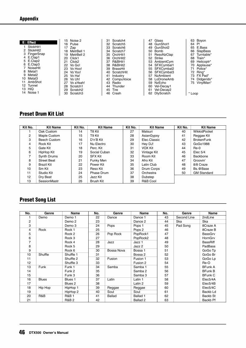
Appendix
Preset Drum Kit List
Preset Song List
1 StickHit12 StickHit23 FingerSnap4 E.Clap15 E.Clap26 E.Clap37 NoiseHit8 Metal19 Metal2
10 Metal311 AmbShot12 Tunnel13 HiQ14 Noise 1
15 Noise 216 Pulse17 Zap18 MetrBell 119 MetrBell 220 Click121 Click222 Vo Go!23 Vo Hoo!24 Vo Yoo!25 Vo Ha!26 Vo Uh!27 Vo aYeah!28 Scratch129 Scratch230 Scratch3
31 Scratch432 Scratch533 Scratch634 Scratch735 OrchHit136 OrchHit237 R&BHit138 R&BHit239 BrassHit40 ScratchHit41 Industry42 CompuVoice43 Radio44 Thunder45 Tire46 Crash
47 Glass48 GunShot149 GunShot250 Bomb51 ResoNzClap52 Strike53 AmbientCym54 SFXCymbal155 SFXCymbal256 SFXCymbal357 NzAmbient 58 LoDroneAmb59 NzEcho60 Vel-Decay161 Vel-Decay262 DlyScratch
63 Boyon64 P!65 E.Bass66 SlapBass67 Turntable*68 Train*69 Helicoptr*70 Applause*71 Police*72 Ring*73 FX Pad*74 Didgerido*75 VinylMan*
* Loop
EEEE :::: EEEEffffffffeeeecccctttt
Kit No. Kit Name1 Oak Custom2 Maple Custom3 Beech Custom4 Rock Kit5 Gate Kit6 HipHop Kit7 Synth Drums8 Street Beat9 Brazil Kit
10 Sm Kit11 Studio Kit12 Dry Beat13 SessionMastr
14 T8 Kit15 T9 Kit16 D’n’B Kit17 Nu Electro18 Perc. Kit19 Social Cuban20 SFX Kit21 Funky Men22 Power Kit23 Reso Kit24 Phase Drum25 Jazz Kit26 Brush Kit
Kit No. Kit Name27 Matsuri28 AsianGypsy29 Elec.Classic30 Hey DJ!31 VOX Kit32 Vintage Kit33 Room Kit34 Afro Kit35 Latin Club36 Drum Corps37 Orchestra38 Dubstep39 R&B Cool
Kit No. Kit Name40 WikkidPocket41 Reggae Kit42 BrokenFunk43 GoGo198844 Re-045 Elec 5/446 Backbone47 Groovin’48 8/8 Craze49 Bs.@Base50 GM Standard
Kit No. Kit Name
No. Genre Name1 Demo Demo 12 Demo 23 Demo 34 Rock Rock 15 Rock 26 Rock 37 Rock 48 Rock 59 Rock 6
10 Shuffle Shuffle 111 Shuffle 212 Shuffle 313 Funk Funk 114 Funk 215 Funk 316 Blues Blues 117 Blues 218 Hip Hop HipHop 119 HipHop 220 R&B R&B 121 R&B 2
22 Dance Dance 123 Dance 224 Pops Pops 125 Pops 226 Pop Rock PopRock127 PopRock228 Jazz Jazz 129 Jazz 230 Bossa Nova Bossa 131 Bossa 232 Fusion Fusion 133 Fusion 234 Samba Samba 135 Samba 236 Samba 337 Latin Latin 138 Latin 239 Reggae Reggae40 Soul Soul41 Ballad Ballad 142 Ballad 2
No. Genre Name43 Second Line 2ndLine44 Ska Ska45 Pad Song 8Craze A46 8Craze B47 BassGrv48 HornGrv49 BassRiff50 PadBass51 GoGo Tp52 GoGo Br53 GoGo Lp54 Re-O55 BFunk A56 BFunk B57 BFunk C58 Elec5/4A59 Elec5/4B60 Elec5/4C61 Backb Ld62 Backb St63 Backb Pf
No. Genre Name
46 DTX500 Owner’s Manual
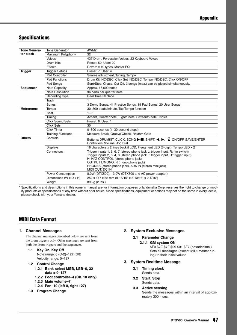
47
DTX500 Owner’s Manual
Appendix
Specifications
* Specifications and descriptions in this owner’s manual are for information purposes only. Yamaha Corp. reserves the right to change or mod-ify products or specifications at any time without prior notice. Since specifications, equipment or options may not be the same in every locale, please check with your Yamaha dealer.
MIDI Data Format
1. Channel Messages
The channel messages described below are sent from the drum triggers only. Other messages are sent from both the drum triggers and the sequencer.
1.1 Key On, Key Off
Note range: 0 (C-2)–127 (G8)Velocity range: 0–127
1.2 Control Change1.2.1 Bank select MSB, LSB–0, 32
data = 0–1271.2.2 Foot controller–4 (Ch. 10 only)1.2.3 Main volume–71.2.4 Pan–10 (left 0, right 127)
1.3 Program Change
2. System Exclusive Messages
2.1 Parameter Change2.1.1 GM system ON
$F0 $7E $7F $09 $01 $F7 (hexadecimal)Sets all messages (except MIDI master tun-ing) to their initial values.
3. System Realtime Message
3.1 Timing clock
Sends data.
3.2 Start, Stop
Sends data.
3.3 Active sensing
Sends the messages within an interval of approxi-mately 300 msec.
Tone Genera-tor block
Tone Generator AWM2Maximum Polyphony 32Voices 427 Drum, Percussion Voices, 22 Keyboard VoicesDrum Kits Preset: 50, User: 20Effects Reverb x 19 types, Master EQ
Trigger
Trigger Setups Preset: 7, User: 4Pad Controller Snares adjustment, Tuning, TempoPad Functions Drum Kit INC/DEC, Click Set INC/DEC, Tempo INC/DEC, Click ON/OFFPad Songs Start/Stop, Chase, Cut Off, 3 songs (max.) can be played simultaneously.
Sequencer
Note Capacity Approx. 16,000 notesNote Resolution 96 parts per quarter noteRecording Type Real Time ReplaceTrack 1Songs 3 Demo Songs, 41 Practice Songs, 19 Pad Songs, 20 User Songs
Metronome
Tempo 30–300 beats/minute, Tap Tempo functionBeat 1–9Timing Accent, Quarter note, Eighth note, Sixteenth note, TripletClick Sound Sets Preset: 6, User: 1Click Sets 30Click Timer 0–600 seconds (in 30-second steps)Training Functions Measure Break, Groove Check, Rhythm Gate
Others
Controls Buttons: DRUMKIT, CLICK, SONG
>
/
, SHIFT,
<
,
>
, ON/OFF, SAVE/ENTERControllers: Volume, Jog Dial
Displays 16 characters x 2 lines backlit LCD, 7-segment LED (3-digit), Tempo LED x 2Connectors Trigger inputs 1, 5, 6, 7 (stereo phone jack L: trigger input, R: rim switch)
Trigger inputs 2, 3, 4, 8 (stereo phone jack L: trigger input, R: trigger input)HI HAT CONTROL (stereo phone jack)OUTPUT L/MONO, R (mono phone jack)PHONES (stereo phone jack), AUX IN (stereo mini jack)MIDI OUT, DC IN
Power Consumption 8.0W (DTX500), 13.0W (DTX500 and AC power adapter)Dimensions (W x D x H) 252 x 147 x 52 mm (9-15/16" x 5-13/16" x 2-1/16")Weight 898 g (2 lbs.)
For details of products, please contact your nearest Yamaha representative or the authorized distributor listed below.
Pour plus de détails sur les produits, veuillez-vous adresser à Yamaha ou au distributeur le plus proche de vous figurant dans la liste suivante.
Die Einzelheiten zu Produkten sind bei Ihrer unten aufgeführten Niederlassung und bei Yamaha Vertragshändlern in den jeweiligen Bestimmungsländern erhältlich.
Para detalles sobre productos, contacte su tienda Yamaha más cercana o el distribuidor autorizado que se lista debajo.
CANADAYamaha Canada Music Ltd.135 Milner Avenue, Scarborough, Ontario,M1S 3R1, CanadaTel: 416-298-1311
U.S.A.Yamaha Corporation of America 6600 Orangethorpe Ave., Buena Park, Calif. 90620, U.S.A.Tel: 714-522-9011
MEXICOYamaha de México S.A. de C.V.Calz. Javier Rojo Gómez #1149,Col. Guadalupe del MoralC.P. 09300, México, D.F., MéxicoTel: 55-5804-0600
BRAZILYamaha Musical do Brasil Ltda.Rua Joaquim Floriano, 913 - 4' andar, Itaim Bibi, CEP 04534-013 Sao Paulo, SP. BRAZILTel: 011-3704-1377
ARGENTINAYamaha Music Latin America, S.A. Sucursal de ArgentinaOlga Cossettini 1553, Piso 4 NorteMadero Este-C1107CEKBuenos Aires, ArgentinaTel: 011-4119-7000
PANAMA AND OTHER LATIN AMERICAN COUNTRIES/CARIBBEAN COUNTRIES
Yamaha Music Latin America, S.A.Torre Banco General, Piso 7, Urbanización Marbella, Calle 47 y Aquilino de la Guardia, Ciudad de Panamá, Panamá Tel: +507-269-5311
THE UNITED KINGDOM/IRELANDYamaha Music U.K. Ltd.Sherbourne Drive, Tilbrook, Milton Keynes, MK7 8BL, EnglandTel: 01908-366700
GERMANYYamaha Music Europe GmbHSiemensstraße 22-34, 25462 Rellingen, GermanyTel: 04101-3030
SWITZERLAND/LIECHTENSTEINYamaha Music Europe GmbH Branch Switzerland in ZürichSeefeldstrasse 94, 8008 Zürich, SwitzerlandTel: 01-383 3990
AUSTRIAYamaha Music Europe GmbH Branch AustriaSchleiergasse 20, A-1100 Wien, AustriaTel: 01-60203900
CZECH REPUBLIC/SLOVAKIA/HUNGARY/SLOVENIA
Yamaha Music Europe GmbH Branch AustriaSchleiergasse 20, A-1100 Wien, Austria Tel: 01-602039025
POLAND/LITHUANIA/LATVIA/ESTONIAYamaha Music Europe GmbH Branch Sp.z o.o. Oddzial w Polsceul. 17 Stycznia 56, PL-02-146 Warszawa, PolandTel: 022-868-07-57
THE NETHERLANDS/BELGIUM/LUXEMBOURG
Yamaha Music Europe Branch BeneluxClarissenhof 5-b, 4133 AB Vianen, The Netherlands Tel: 0347-358 040
FRANCEYamaha Musique France BP 70-77312 Marne-la-Vallée Cedex 2, FranceTel: 01-64-61-4000
ITALYYamaha Musica Italia S.P.A. Combo DivisionViale Italia 88, 20020 Lainate (Milano), Italy Tel: 02-935-771
SPAIN/PORTUGALYamaha Música Ibérica, S.A.Ctra. de la Coruna km. 17, 200, 28230 Las Rozas (Madrid), SpainTel: 91-639-8888
GREECEPhilippos Nakas S.A. The Music House147 Skiathou Street, 112-55 Athens, GreeceTel: 01-228 2160
SWEDENYamaha Scandinavia ABJ. A. Wettergrens Gata 1, Box 30053S-400 43 Göteborg, SwedenTel: 031 89 34 00
DENMARKYS Copenhagen Liaison OfficeGeneratorvej 6A, DK-2730 Herlev, DenmarkTel: 44 92 49 00
FINLANDF-Musiikki OyKluuvikatu 6, P.O. Box 260, SF-00101 Helsinki, FinlandTel: 09 618511
NORWAYNorsk filial av Yamaha Scandinavia AB Grini Næringspark 1, N-1345 Østerås, Norway Tel: 67 16 77 70
ICELANDSkifan HFSkeifan 17 P.O. Box 8120, IS-128 Reykjavik, IcelandTel: 525 5000
RUSSIAYamaha Music (Russia)Office 4015, entrance 2, 21/5 Kuznetskii Most street, Moscow, 107996, RussiaTel: 495 626 0660
OTHER EUROPEAN COUNTRIESYamaha Music Europe GmbHSiemensstraße 22-34, 25462 Rellingen, GermanyTel: +49-4101-3030
Yamaha Corporation, Asia-Pacific Music Marketing GroupNakazawa-cho 10-1, Naka-ku, Hamamatsu, Japan 430-8650Tel: +81-53-460-2312
TURKEY/CYPRUSYamaha Music Europe GmbHSiemensstraße 22-34, 25462 Rellingen, GermanyTel: 04101-3030
OTHER COUNTRIESYamaha Music Gulf FZELOB 16-513, P.O.Box 17328, Jubel Ali, Dubai, United Arab EmiratesTel: +971-4-881-5868
THE PEOPLE’S REPUBLIC OF CHINAYamaha Music & Electronics (China) Co.,Ltd.2F, Yunhedasha, 1818 Xinzha-lu, Jingan-qu, Shanghai, ChinaTel: 021-6247-2211
HONG KONGTom Lee Music Co., Ltd.11/F., Silvercord Tower 1, 30 Canton Road,Tsimshatsui, Kowloon, Hong KongTel: 2737-7688
INDIAYamaha Music India Pvt. Ltd.5F Ambience Corporate Tower Ambience Mall ComplexAmbience Island, NH-8, Gurgaon-122001, Haryana, IndiaTel: 0124-466-5551
INDONESIAPT. Yamaha Music Indonesia (Distributor)PT. NusantikGedung Yamaha Music Center, Jalan Jend. Gatot Subroto Kav. 4, Jakarta 12930, IndonesiaTel: 21-520-2577
KOREAYamaha Music Korea Ltd.8F, 9F, Dongsung Bldg. 158-9 Samsung-Dong, Kangnam-Gu, Seoul, KoreaTel: 080-004-0022
MALAYSIAYamaha Music Malaysia, Sdn., Bhd.Lot 8, Jalan Perbandaran, 47301 Kelana Jaya, Petaling Jaya, Selangor, MalaysiaTel: 3-78030900
PHILIPPINESYupangco Music Corporation339 Gil J. Puyat Avenue, P.O. Box 885 MCPO, Makati, Metro Manila, PhilippinesTel: 819-7551
SINGAPOREYamaha Music Asia Pte., Ltd.#03-11 A-Z Building140 Paya Lebor Road, Singapore 409015Tel: 747-4374
TAIWANYamaha KHS Music Co., Ltd. 3F, #6, Sec.2, Nan Jing E. Rd. Taipei.Taiwan 104, R.O.C.Tel: 02-2511-8688
THAILANDSiam Music Yamaha Co., Ltd.4, 6, 15 and 16th floor, Siam Motors Building, 891/1 Rama 1 Road, Wangmai, Pathumwan, Bangkok 10330, ThailandTel: 02-215-2626
OTHER ASIAN COUNTRIES Yamaha Corporation,Asia-Pacific Music Marketing GroupNakazawa-cho 10-1, Naka-ku, Hamamatsu, Japan 430-8650Tel: +81-53-460-2317
AUSTRALIAYamaha Music Australia Pty. Ltd.Level 1, 99 Queensbridge Street, Southbank, Victoria 3006, AustraliaTel: 3-9693-5111
NEW ZEALANDMusic Works LTDP.O.BOX 6246 Wellesley, Auckland 4680, New ZealandTel: 9-634-0099
COUNTRIES AND TRUST TERRITORIES IN PACIFIC OCEAN
Yamaha Corporation,Asia-Pacific Music Marketing GroupNakazawa-cho 10-1, Naka-ku, Hamamatsu, Japan 430-8650Tel: +81-53-460-2312
NORTH AMERICA
CENTRAL & SOUTH AMERICA
EUROPE
AFRICA
MIDDLE EAST
ASIA
OCEANIA
HEAD OFFICE Yamaha Corporation, Pro Audio & Digital Musical Instrument DivisionNakazawa-cho 10-1, Naka-ku, Hamamatsu, Japan 430-8650 Tel: +81-53-460-2432
SY51
Yamaha Electronic Drums web site:http://www.yamaha.co.jp/english/product/drums/ed/
Yamaha Manual Libraryhttp://www.yamaha.co.jp/manual/
003PO***.*-01B0
U.R.G., Pro Audio & Digital Musical Instrument Division, Yamaha Corporation© 2010 Yamaha Corporation
WU53720Printed in Vietnam
dtx500_en_3.fm Page 48 Tuesday, March 23, 2010 11:48 AM