Embed Size (px)
Citation preview
01/2004 - Art. Nr. 13 012 338A
EK02B.12 GEK02B.18 G
BetriebsanleitungFür die autorisierte FachkraftGasgebläsebrenner .............................2-15
Operating instructionsFor the authorized specialistGas burners .......................................16-29 EN
DE
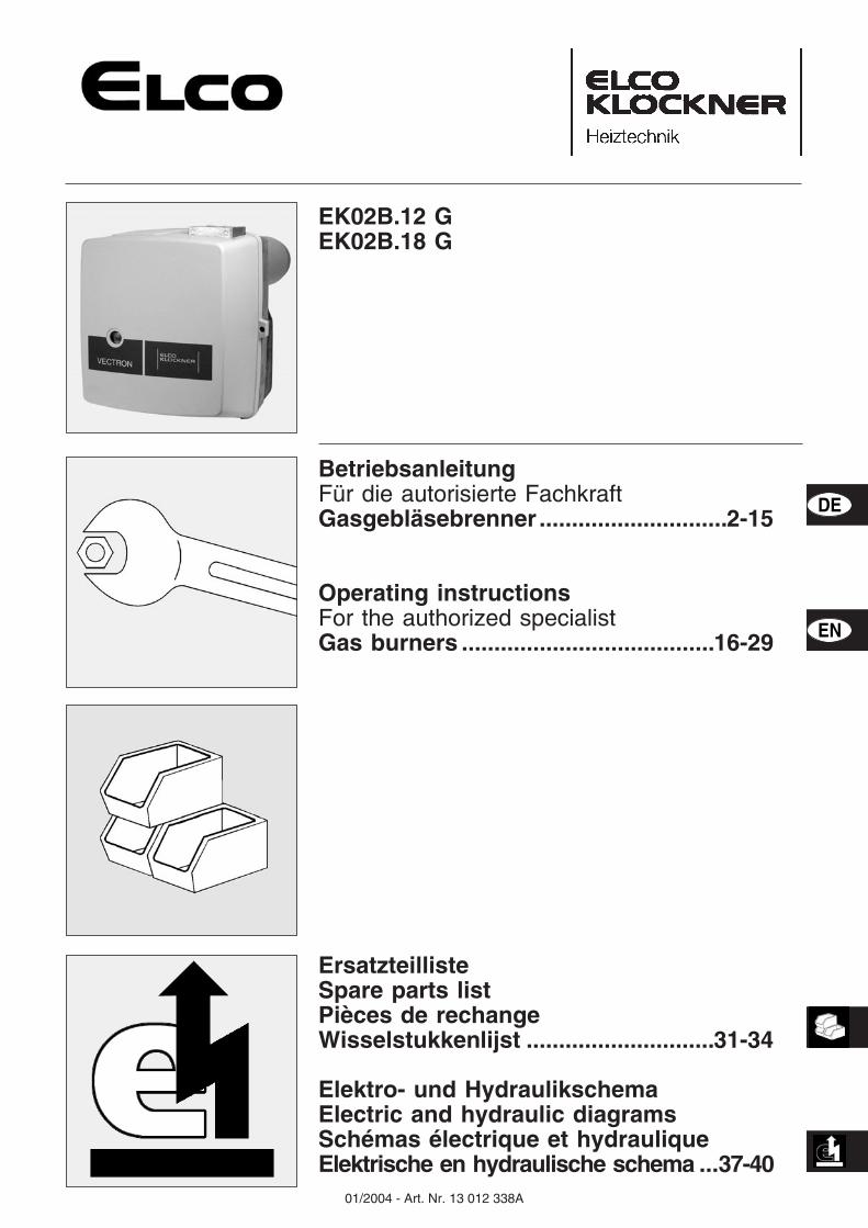
ErsatzteillisteSpare parts listPièces de rechangeWisselstukkenlijst .............................31-34
Elektro- und HydraulikschemaElectric and hydraulic diagramsSchémas électrique et hydrauliqueElektrische en hydraulische schema ...37-40
01/2004 - Art. Nr. 13 012 338A2
Übersicht
Inhaltsverzeichnis
SeiteÜbersicht Inhaltsverzeichnis. . . . . . . . . . . . . . . . . . . . . 2
Wichtige Hinweise . . . . . . . . . . . . . . . . . . . . 2Technische Daten, Arbeitsfelder . . . . . . . . . . . . . 3Abmessungen, Brennerbeschreibung . . . . . . . . . . 4
Funktion Kompaktarmatur . . . . . . . . . . . . . . . . . . . . . 5Betriebsfunktion, Sicherheitsfunktion . . . . . . . . . . . 6Feuerungsautomat . . . . . . . . . . . . . . . . . . . . 7
Montage Brennermontage . . . . . . . . . . . . . . . . . . . . . 8Gasversorgung, Elektrische Versorgung . . . . . . . . . 9Prüfung vor Inbetriebnahme . . . . . . . . . . . . . . . 9Prüfung / Einstellung . . . . . . . . . . . . . . . . . . 10Mischeinrichtung für Erdgas . . . . . . . . . . . . . . 10
Inbetriebnahme Einstellung des Brenners/Luftregulierung . . . . . . . . 11Einstellung des Brenners/Einstellung der Gasmenge . . 12Brennereinstelldaten . . . . . . . . . . . . . . . . . . 13
Service Wartung . . . . . . . . . . . . . . . . . . . . . . . . . 14Störungsbeseitigung . . . . . . . . . . . . . . . . . . 15
Konformitätserklärungfür Gasgebläsebrenner
Wir, CEBF-74106 ANNEMASSE Cedexerklären in alleiniger Verantwortung.dass die Produkte
EK02B.12 GEK02B.18 G
mit folgenden Normen übereinstim-menEN 50165EN 55014EN 60335EN 60555-2EN 60555-3EN 676
Gemäß den Bestimmungen derRichtlinien
89 / 396 /EWG Gasgeräte89 / 336 /EWG EMV-Richtlinie73 / 23 /EWG Niederspannungs-
richtlinie92 / 42 /EWG Wirkungsgrad-
richtlinie97 / 23 /EWG Druckgeräterichtlinie
werden diese Produkte CE-gekenn-zeichnet.
Annemasse, den 1. Oktober 2003J.HAEP
BrennerbeschreibungDie Brenner EK02B... G sind 1-stufige,vollautomatisch arbeitende Brenner inMonoblockausführung. Sie sindgeeignet zur Ausrüstung aller derEN303 entsprechenden Wärmeerzeu-ger innerhalb ihres Leistungsbereiches.Jede andere Verwendungsart erfordertdie Genehmigung von ELCO Klöckner.
Wichtige HinweiseDer Brenner entspricht in Aufbau undFunktion der EN676.Montage, Inbetriebnahme und Wartungdürfen ausschließlich von autorisiertenFachkräften ausgeführt werden, wobeidie geltenden Richtlinien und Vorschrif-ten zu beachten sind.Bei der Montage der Gasleitungen undArmaturen sind ebenfalls die geltendenRichtlinien und Vorschriften zu beachten(z.B. DVGW-TRGI 1986/96 ; TRF 1988 ;DIN 4756).Es dürfen nur Dichtungsmaterialienverwendet werden, die DVGW geprüftund zugelassen sind. Dichtheit der Ver-bindungsstellen mit schaumbildendenMitteln oder ähnlichen, die keineKorrosion verursachen, prüfen.Vor Inbetriebnahme ist die Gasleitungzu entlüften. Die Entlüftung darf aufkeinen Fall über den Feuerraum erfolgen.Instandsetzungsarbeiten an Wächtern,Begrenzern und Feuerungsautomatensowie an anderen Sicherheitseinrichtun-gen, dürfen nur von den jeweiligen Her-stellern oder dessen Beauftragten anden Einzeleinrichtungen durchgeführtwerden. Der Austausch von Originaltei-len ist nur durch die Fachkraft zulässig.
LieferumfangDer Brenner wird in zwei Verpackungs-einheiten geliefert :� Brenner mit Brennkopf, Flanschdich-
tung und Befestigungsschrauben, mitBetriebsanleitung, Stromlaufplan,Ersatzteilliste, Heizraumtafel.
� Gasarmaturengruppe.
Für einen sicheren, umweltgerechtenund energiesparenden Betrieb sindfolgende Normen zu berücksichtigen:
EN 676Gasbrenner mit Gebläse
EN 60335-2Sicherheit elektrischer Geräte für denHausgebrauchDie Gasleitungen und Armaturenmüssen nach DVGW-TVR/TRGI-Gasverlegt werden.
AufstellungsortDer Brenner darf nicht in Räumen mitaggressiven Dämpfen (z.B. Haarspray,Perchloräthylen, Tetrachlorkohlenstoff),starkem Staubanfall oder hoher Luft-feuchtigkeit (z.B. Waschküchen) inBetrieb genommen werden.Eine Zuluftöffnung muss vorhanden sein:– bis 50kW: 150cm²– für jedes weitere kW: +2cm²Aus kommunalen Vorschriften könnensich Abweichungen ergeben.
Für Schäden, die sich aus folgendenGründen ergeben, schließen wir dieGewährleistung aus:– unsachgemäße Verwendung– fehlerhafte Montage bzw. Instandset-
zung durch Käufer oder Dritte, ein-schließlich Einbringen von Teilenfremder Herkunft.
Übergabe undBedienungsanweisungDer Ersteller der Feuerungsanlage hatdem Betreiber der Anlage, spätestensbei der Übergabe, eine Bedienungs-und Wartungsanweisung zu übergeben.Diese ist im Aufstellungsraum des Wär-meerzeugers gut sichtbar auszuhän-gen. Die Anschrift und Rufnummer dernächsten Kundendienststelle ist einzu-tragen.
Hinweis für den BetreiberDie Anlage sollte jährlich mindestenseinmal von einer Fachkraft überprüftwerden. Um eine regelmäßige Durch-führung zu gewährleisten, empfiehltsich der Abschluss eines Wartungsver-trages.
01/2004 - Art. Nr. 13 012 338A 3
Übersicht
Technische DatenArbeitsfelder
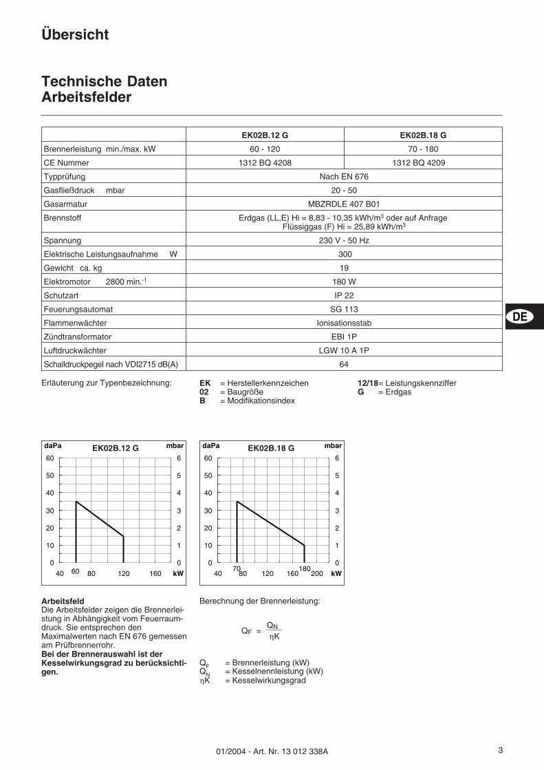
Erläuterung zur Typenbezeichnung: EK = Herstellerkennzeichen02 = BaugrößeB = Modifikationsindex
12/18= LeistungskennzifferG = Erdgas
Berechnung der Brennerleistung:
QF = Brennerleistung (kW)QN = Kesselnennleistung (kW)�K = Kesselwirkungsgrad
QNQF =�K
ArbeitsfeldDie Arbeitsfelder zeigen die Brennerlei-stung in Abhängigkeit vom Feuerraum-druck. Sie entsprechen denMaximalwerten nach EN 676 gemessenam Prüfbrennerrohr.Bei der Brennerauswahl ist derKesselwirkungsgrad zu berücksichti-gen.
daPa mbar
kW600
10
20
30
40
50
60
40 80 120 160
0
1
2
3
4
5
6EK02B.12 G daPa mbar
kW18070
0
10
20
30
40
50
60
40 80 120 160 200
0
1
2
3
4
5
6EK02B.18 G
DE
EK02B.12 G EK02B.18 G
Brennerleistung min./max. kW 60 - 120 70 - 180
CE Nummer 1312 BQ 4208 1312 BQ 4209
Typprüfung Nach EN 676
Gasfließdruck mbar 20 - 50
Gasarmatur MBZRDLE 407 B01
Brennstoff Erdgas (LL,E) Hi = 8,83 - 10,35 kWh/m3 oder auf AnfrageFlüssiggas (F) Hi = 25,89 kWh/m3
Spannung 230 V - 50 Hz
Elektrische Leistungsaufnahme W 300
Gewicht ca. kg 19
Elektromotor 2800 min.-1 180 W
Schutzart IP 22
Feuerungsautomat SG 113
Flammenwächter Ionisationsstab
Zündtransformator EBI 1P
Luftdruckwächter LGW 10 A 1P
Schalldruckpegel nach VDI2715 dB(A) 64
01/2004 - Art. Nr. 13 012 338A4
Übersicht
AbmessungenBrennerbeschreibung
115
125
H
H
J
J
Rp 3/4
37
0
280
75
φ2
10
K
210
28029
0 φ1
50
-18
0
M8
45°
T
K
185
16
514
0
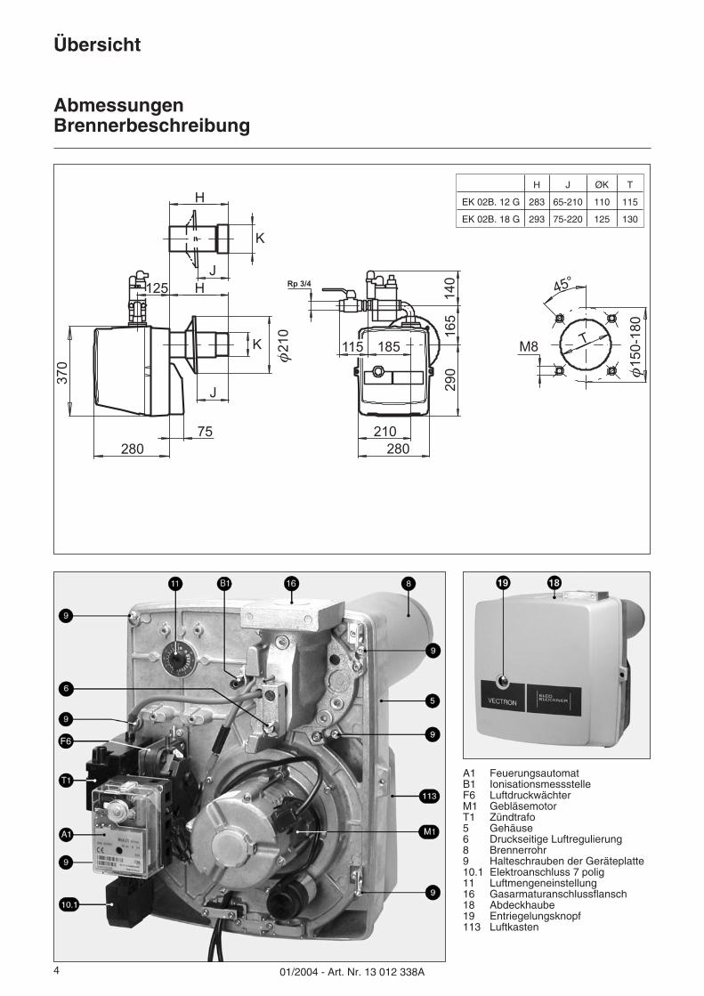
A1 FeuerungsautomatB1 IonisationsmessstelleF6 LuftdruckwächterM1 GebläsemotorT1 Zündtrafo5 Gehäuse6 Druckseitige Luftregulierung8 Brennerrohr9 Halteschrauben der Geräteplatte10.1 Elektroanschluss 7 polig11 Luftmengeneinstellung16 Gasarmaturanschlussflansch18 Abdeckhaube19 Entriegelungsknopf113 Luftkasten
H J ØK T
EK 02B. 12 G 283 65-210 110 115
EK 02B. 18 G 293 75-220 125 130
501/2004 - Art. Nr. 13 012 338A
Funktion
Kompaktarmatur
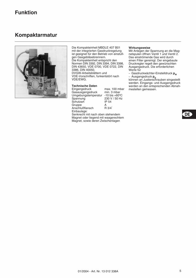
WirkungsweiseMit Anlegen der Spannung an die Mag-netspulen öffnen Ventil 1 und Ventil 2.Das einströmende Gas wird durcheinen Filter gereinigt. Der eingebauteDruckregler regelt den gewünschtenAusgangsdruck. Die erforderlichenWerte für– Gasdruckwächter-Einstelldruck pW– Ausgangsdruck pGkönnen an Justierschrauben eingestelltwerden. Eingangs- und Ausgangsdruckwerden an den entsprechenden Abnah-mestellen gemessen.
Die Kompakteinheit MBDLE 407 B01mit der integrierten Gasdruckregelungist geeignet für den Betrieb von einstufi-gen Gasgebläsebrennern.Die Kompakteinheit entspricht denNormen DIN 3392, DIN 3394, DIN 3398,DIN 43650, VDE 0700, VDE 0722, DIN3386, DIN 40050,DVGW-Arbeitsblättern undVDE-Vorschriften, funkentstört nachVDE/EWG.
Technische DatenEingangsdruck max. 100 mbarGasausgangsdruck min. 3 mbarUmgebungstemperatur -10 bis +60oCSpannung 230 V / 50 HzSchutzart IP 54Gruppe AAnschlußflansch R 3/4“
Einbaulage:Senkrecht mit nach oben stehendemMagnet oder liegend mit waagerechtemMagnet, sowie deren Zwischenlagen
DE
01/2004 - Art. Nr. 13 012 338A6
Funktion
BetriebsfunktionSicherheitsfunktion
Funktionsbeschreibung– Regelthermostat fordert Wärme an.– Das Steuerprogramm des Steuerge-
rätes läuft an, wenn der Luftdruck-wächterkontakt in Ruhestellung istund vom Gasdruckwächter ausrei-chend Gasdruck gemeldet wird.
– Brennermotor läuft an.– Vorbelüftungszeit läuft.
Während der Vorspülzeit wird– der Gebläsedruck überwacht– der Feuerraum auf Flammensignale
geprüft.
Nach Ablauf der Vorspülzeit– wird die Zündung zugeschaltet– wird das Haupt- und Sicherheitsmag-
netventil geöffnet.– Brennerstart
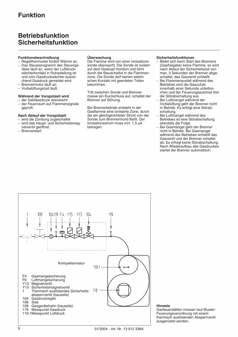
ÜberwachungDie Flamme wird von einer Ionisations-sonde überwacht. Die Sonde ist isoliertauf dem Gaskopf montiert und führtdurch die Stauscheibe in die Flammen-zone. Die Sonde darf keinen elektri-schen Kontakt mit geerdeten Teilenbekommen.
Tritt zwischen Sonde und Brenner-masse ein Kurzschluss auf, schaltet derBrenner auf Störung.
Bei Brennerbetrieb entsteht in derGasflamme eine ionisierte Zone, durchdie ein gleichgerichteter Strom von derSonde zum Brennermund fließt. DerIonisationsstrom muss min. 1,5 µAbetragen.
Sicherheitsfunktionen– Bildet sich beim Start des Brenners
(Gasfreigabe) keine Flamme, so wirdnach Ablauf der Sicherheitszeit vonmax. 3 Sekunden der Brenner abge-schaltet, das Gasventil schließt.
– Bei Flammenausfall während desBetriebes wird die Gaszufuhrinnerhalb einer Sekunde unterbro-chen und der Feuerungsautomat löstdie Störabschaltung aus.
– Bei Luftmangel während derVorbelüftung geht der Brenner nichtin Betrieb. Es erfolgt eine Störab-schaltung.
– Bei Luftmangel während desBetriebes ist eine Störabschaltungebenfalls die Folge.
– Bei Gasmangel geht der Brennernicht in Betrieb. Bei Gasmangelwährend des Betriebes schließt dasGasventil und der Brenner schaltetab. Es erfolgt keine Störabschaltung.Nach Wiederaufbau des Gasdruckesstartet der Brenner automatisch.
F4 GasmangelsicherungF6 LuftmangelsicherungY13 MagnetventilY15 Sicherheitsmagnetventil1 Thermisch auslösendes Sicherheits-
absperrventil (bauseits)104 Gasdruckregler106 Sieb108 Gasgerätehahn (bauseits)119 Messpunkt Gasdruck119.1Messpunkt Luftdruck
Kompaktarmatur
HinweisGasfeuerstätten müssen laut Muster-Feuerungsverordnung mit einemthermisch auslösenden Absperrventilausgerüstet werden.
01/2004 - Art. Nr. 13 012 338A 7
Funktion
Feuerungsautomat SG 113
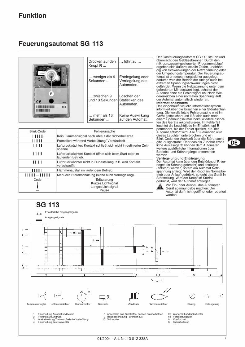
Blink-Code Fehlerursache���������� Kein Flammensignal nach Ablauf der Sicherheitszeit.��� ����� Fremdlicht während Vorbelüftung/ Vorzündzeit����� ��� Luftdruckwächter: Kontakt schließt sich nicht in definierter Zeit-
spanne��� ��� � Luftdruckwächter: Kontakt öffnet sich beim Start oder im
laufenden Betrieb.��� ����� Luftdruckwächter nicht in Ruhestellung, z.B. weil Kontakt
verschweißt.������� � Flammenausfall im laufendem Betrieb.
���������� — ����� ��� Manuelle Störabschaltung (siehe auch Verriegelung).Code
��
—
ErläuterungKurzes LichtsignalLanges Lichtsignal
Pause
Erforderliche Eingangssignale
Ausgangssignale
Der Gasfeuerungsautomat SG 113 steuert undüberwacht den Gebläsebrenner. Durch denmikroprozessor-gesteuerten Programmablaufergeben sich äußerst stabile Zeiten, unabhän-gig von Schwankungen der Netzspannung oderder Umgebungstemperatur. Der Feuerungsau-tomat ist unterspannungssicher ausgelegt,dadurch wird der Betrieb der Anlage auch beiextremen Spannungsschwankungen nichtgefährdet. Wenn die Netzspannung unter demgeforderten Mindestwert liegt, schaltet derAutomat ohne ein Fehlersignal ab. Nach Wie-dererreichen einer normalen Spannung läuftder Automat automatisch wieder an.InformationssystemDas eingebaute visuelle Informationssysteminformiert über die Ursachen einer Störabschal-tung. Die jeweils letzte Fehlerursache wird imGerät gespeichert und läßt sich auch nacheinem Spannungsausfall beim Wiedereinschal-ten des Geräts rekonstruieren. Im Fehlerfallleuchtet die Leuchtdiode im Entstörknopf Rpermanent, bis der Fehler quittiert, d.h. derAutomat entstört wird. Alle 10 Sekunden wirddieses Leuchten unterbrochen und einBlink-Code, der Auskunft über die Störursachegibt, ausgestrahlt. Über das als Zubehör erhält-liche Auslesegerät können dem Automatenweitere ausführliche Informationen überBetriebs- und Störvorgänge entnommenwerden.Verriegelung und EntriegelungDer Automat kann über den Entstörknopf R ver-riegelt (in Störung gebracht) und entriegelt(entstört) werden, sofern am Automat Netz-spannung anliegt. Wird der Knopf im Normalbe-trieb oder Anlauf gedrückt, so geht das Gerät inStörstellung. Wird der Knopf im Störfallgedrückt, wird der Automat entriegelt.
�Vor Ein- oder Ausbau des AutomatenGerät spannungslos machen. DerAutomat darf nicht geöffnet oder repariertwerden.
Drücken auf denKnopf R ...
… führt zu …
… weniger als 9Sekunden ...
Entriegelung oderVerriegelung desAutomaten.
… zwischen 9und 13 Sekunden...
Löschen derStatistiken desAutomaten.
… mehr als 13Sekunden ...
Keine Auswirkungauf den Automat.
1 Einschaltung Automat und Motor2 Prüfung auf Luftdruck3 Inbetriebsetzung Trafo und Ende der Vorbelüftung4 Einschaltung des Gasventils
5 Abschalten des Zündtrafos, danach Brennerbetrieb0 Regelabschaltung - Brenner aus
10 Störmodus
tlw Wartezeit Luftdruckwächtertlk Vorbelüftungszeittvz Vorzündzeitts Sicherheitszeit
Temperaturregler Luftdruckwächter Brennermotor Gasventil Zündtrafo Flammenwächter Störung Entriegelung
DE
01/2004 - Art. Nr. 13 012 338A8
Montage
Brennermontage
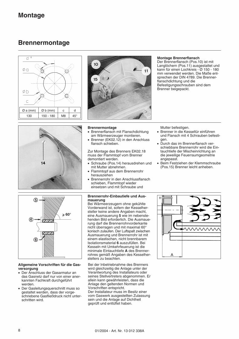
Montage BrennerflanschDer Brennerflansch (Pos.10) ist mitLanglöchern (Pos.11) ausgestattet undkann für einen Lochkreis - Ø 150 - 180mm verwendet werden. Die Maße ent-sprechen der DIN 4789. Die Brenner-flanschdichtung und dieBefestigungsschrauben sind demBrenner beigepackt.
Brennerrohr-Einbautiefe und Aus-mauerungBei Wärmeerzeugern ohne gekühlteVorderwand ist, sofern der Kesselher-steller keine andere Angaben macht,eine Ausmauerung 5 wie im nebenste-henden Bild erforderlich. Die Ausmaue-rung darf die Brennerrohrvorderkantenicht überragen und mit maximal 60°konisch zulaufen. Der Luftspalt zwischenAusmauerung und Brennerrohr ist miteinem elastischen, nicht brennbaremIsolationsmaterial 6 auszufüllen. BeiKesseln mit Umkehrfeuerung ist dieminimale Eintauchtiefe A des Brenner-rohres gemäß Angaben des Kesselher-stellers zu beachten.
5
4
6
Ø a (mm) Ø b (mm) c d
130 150 - 180 M8 45°
Allgemeine Vorschriften für die Gas-versorgung� Der Anschluss der Gasarmatur an
das Gasnetz darf nur von einer aner-kannten Fachkraft durchgeführtwerden.
� Der Gasleitungsquerschnitt muss sogestaltet werden, dass der vorge-schriebene Gasfließdruck nicht unter-schritten wird.
Bei der Inbetriebnahme des Brennerswird gleichzeitig die Anlage unter derVerantwortung des Installateurs oderseines Stellvertreters abgenommen. Erallein kann gewährleisten, dass dieAnlage den geltenden Normen undVorschriften entspricht.Der Installateur muss im Besitz einervom Gaswerk ausgestellten Zulassungsein und die Anlage auf Dichtheitgeprüft und entlüftet haben.
Brennermontage� Brennerflansch mit Flanschdichtung
am Wärmeerzeuger montieren.� Brenner (EK02.12) in den Anschluss
flansch schieben.
Zur Montage des Brenners EK02.18muss der Flammtopf vom Brennerdemontiert werden.� Schraube (Pos.14) herausdrehen und
mit Mutter abnehmen.� Flammtopf aus dem Brennerrohr
herausziehen� Brennerrohr in den Anschlussflansch
schieben, Flammtopf wiedereinsetzen und mit Schraube und
Mutter befestigen.� Brenner in die Kesseltür einführen
und Flansch mit 4 Schrauben befesti-gen.
� Durch das im Brennerflansch ver-schiebbare Brennerrohr wird die Ein-tauchtiefe der Mischeinrichtung andie jeweilige Feuerraumgeometrieangepasst.
� Beim Festziehen der Klemmschraube(Pos.15) Brenner leicht anheben.
01/2004 - Art. Nr. 13 012 338A 9
Montage
GasversorgungElektrische VersorgungPrüfung vor Inbetriebnahme
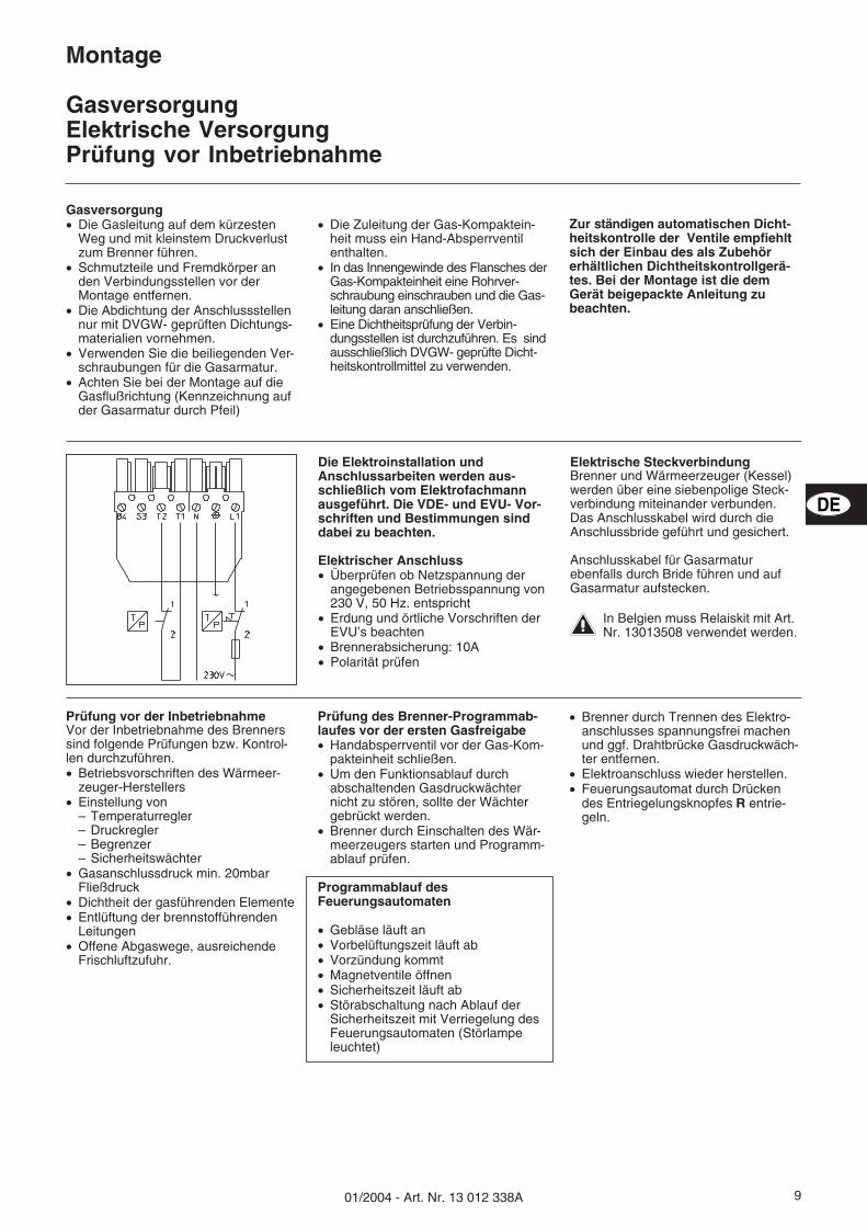
Die Elektroinstallation undAnschlussarbeiten werden aus-schließlich vom Elektrofachmannausgeführt. Die VDE- und EVU- Vor-schriften und Bestimmungen sinddabei zu beachten.
Elektrischer Anschluss� Überprüfen ob Netzspannung der
angegebenen Betriebsspannung von230 V, 50 Hz. entspricht
� Erdung und örtliche Vorschriften derEVU’s beachten
� Brennerabsicherung: 10A� Polarität prüfen
Elektrische SteckverbindungBrenner und Wärmeerzeuger (Kessel)werden über eine siebenpolige Steck-verbindung miteinander verbunden.Das Anschlusskabel wird durch dieAnschlussbride geführt und gesichert.
Anschlusskabel für Gasarmaturebenfalls durch Bride führen und aufGasarmatur aufstecken.
�In Belgien muss Relaiskit mit Art.Nr. 13013508 verwendet werden.
Prüfung vor der InbetriebnahmeVor der Inbetriebnahme des Brennerssind folgende Prüfungen bzw. Kontrol-len durchzuführen.� Betriebsvorschriften des Wärmeer-
zeuger-Herstellers� Einstellung von
– Temperaturregler– Druckregler– Begrenzer– Sicherheitswächter
� Gasanschlussdruck min. 20mbarFließdruck
� Dichtheit der gasführenden Elemente� Entlüftung der brennstofführenden
Leitungen� Offene Abgaswege, ausreichende
Frischluftzufuhr.
Prüfung des Brenner-Programmab-laufes vor der ersten Gasfreigabe� Handabsperrventil vor der Gas-Kom-
pakteinheit schließen.� Um den Funktionsablauf durch
abschaltenden Gasdruckwächternicht zu stören, sollte der Wächtergebrückt werden.
� Brenner durch Einschalten des Wär-meerzeugers starten und Programm-ablauf prüfen.
Programmablauf desFeuerungsautomaten
� Gebläse läuft an� Vorbelüftungszeit läuft ab� Vorzündung kommt� Magnetventile öffnen� Sicherheitszeit läuft ab� Störabschaltung nach Ablauf der
Sicherheitszeit mit Verriegelung desFeuerungsautomaten (Störlampeleuchtet)
� Brenner durch Trennen des Elektro-anschlusses spannungsfrei machenund ggf. Drahtbrücke Gasdruckwäch-ter entfernen.
� Elektroanschluss wieder herstellen.� Feuerungsautomat durch Drücken
des Entriegelungsknopfes R entrie-geln.
Gasversorgung� Die Gasleitung auf dem kürzesten
Weg und mit kleinstem Druckverlustzum Brenner führen.
� Schmutzteile und Fremdkörper anden Verbindungsstellen vor derMontage entfernen.
� Die Abdichtung der Anschlussstellennur mit DVGW- geprüften Dichtungs-materialien vornehmen.
� Verwenden Sie die beiliegenden Ver-schraubungen für die Gasarmatur.
� Achten Sie bei der Montage auf dieGasflußrichtung (Kennzeichnung aufder Gasarmatur durch Pfeil)
� Die Zuleitung der Gas-Kompaktein-heit muss ein Hand-Absperrventilenthalten.
� In das Innengewinde des Flansches derGas-Kompakteinheit eine Rohrver-schraubung einschrauben und die Gas-leitung daran anschließen.
� Eine Dichtheitsprüfung der Verbin-dungsstellen ist durchzuführen. Es sindausschließlich DVGW- geprüfte Dicht-heitskontrollmittel zu verwenden.
Zur ständigen automatischen Dicht-heitskontrolle der Ventile empfiehltsich der Einbau des als Zubehörerhältlichen Dichtheitskontrollgerä-tes. Bei der Montage ist die demGerät beigepackte Anleitung zubeachten.
DE

01/2004 - Art. Nr. 13 012 338A10
Montage
Prüfung / EinstellungMischeinrichtung für Erdgas
Grundeinstellmaße mm EK02B.12 G EK02B.18 G
Maß A Stauscheibe - Flammtopf 3 0
Maß B Stauscheibe - Gasrohr 23,3 26,3
Maß CStauscheibe - Zündelektrodenspitze
2 2
Maß DStauscheibe - Ionisationselektroden-Isolierkörper
4 4
EK02B.12 G EK02B.18 G
1 Brennerrohr2 Gasdüse3 Bride4 Elektrodenhalterf5 Zündelektrode6 Stauscheibe7 Flammtopf8 Ionisationsstab
Die Mischzündeinrichtung ist werkseitigvoreingestellt. Anlagenbedingt kanneine Nachjustierung erforderlich sein.Hierzu ist das Gasrohr komplett mit derMischzündeinrichtung auszubauen.
Das Grundeinstellmaß A bezieht sichauf Stauscheiben-/GasdüsenstellungSkalenwert = 0
Pos.5 = RegulierschraubePos.6 = Skala
Einstellen von Zündelektrode undIonisationsstabÜberprüfen Sie die Einstellung anhandder angegeben Abstände entsprechendder obenstehenden Skizze.
01/2004 - Art. Nr. 13 012 338A 11
Inbetriebnahme
Einregulierung des Brenners / Luftregulierung
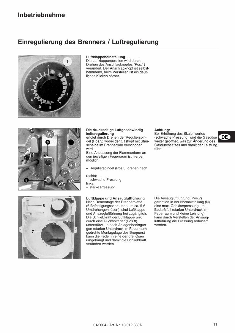
LuftklappeneinstellungDie Luftklappenposition wird durchDrehen des Anschlagknopfes (Pos.1)verändert. Der Anschlagknopf ist selbst-hemmend, beim Verstellen ist ein deut-liches Klicken hörbar.
Luftklappe und AnsaugluftführungNach Demontage der Brennerplatte(6 Befestigungsschrauben um ca. 5-6Umdrehungen lösen), sind Luftklappeund Ansaugluftführung frei zugänglich.Die Schließkraft der Luftklappe wirddurch eine Rückholfeder (Pos.8)unterstützt. Je nach Anlagenbedingun-gen (starker Unterdruck im Feuerraum,gedrehte Montagelage des Brenners)kann die Feder in eine der drei Ösenumgehängt und damit die Schließkraftverändert werden.
Die Ansaugluftführung (Pos.7)garantiert in der Normalstellung (N)eine max. Gebläsepressung. ImBedarfsfall (starker Unterdruck imFeuerraum und kleine Leistung)kann durch Verstellen der Ansaug-luftführung die Pressung reduziertwerden.
Die druckseitige Luftgeschwindig-keitsregulierungerfolgt durch Drehen der Regulierspin-del (Pos.5) wobei der Gaskopf mit Stau-scheibe im Brennerrohr verschobenwird.Eine Anpassung der Flammenform anden jeweiligen Feuerraum ist hierbeimöglich.
� Regulierspindel (Pos.5) drehen nach
rechts:– schwache Pressunglinks:– starke Pressung
Achtung:Bei Erhöhung des Skalenwertes(schwache Pressung) wird die Gasdüseweiter geöffnet, was zur Änderung desGasdurchsatzes und damit der Leistungführt.
DE
01/2004 - Art. Nr. 13 012 338A12
Inbetriebnahme
Einregulierung des Brenners / Einstellung der Gasmenge
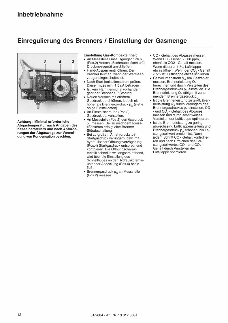
Achtung : Minimal erforderlicheAbgastemperatur nach Angaben desKesselherstellers und nach Anforde-rungen der Abgaswege zur Vermei-dung von Kondensation beachten.
Einstellung Gas-Kompakteinheit� An Messstelle Gasausgangsdruck pG
(Pos.2) Verschlußschraube lösen undDruckmessgerät anschließen
� Hand-Absperrventil öffnen. DerBrenner laüft an, wenn der Wärmeer-zeuger eingeschaltet ist.
� Nach Start Ionisationsstrom prüfen.Dieser muss min. 1,5 µA betragen
� Ist kein Flammensignal vorhanden,geht der Brenner auf Störung.
� Neuen Versuch mit erhötemGasdruck durchführen, jedoch nichthöher als Brennergasdruck pG (sieheobige Einstelldaten)
� An Einstellschraube (Pos.3)Gasdruck pG, verstellen.
� An Messstelle (Pos.2) den GasdruckpG messen. Bei zu niedrigem Ionisa-tionsstrom erfolgt eine Brenner-Störabschaltung
� Bei zu großem Anfahrdruckstoß,Startgasdruck verringern, bzw. mithydraulischer Öffnungsverzögerung(Pos.4) Startgasdruck entsprechendkorrigieren. Die Öffnungscharak-teristik schnell bzw. langsam öffnend,wird über die Einstellung desSchnellhubes an der Hydraulikbremseunter der Abdeckung (Pos.4) beein-flußt
� Brennergasdruck pG an Messstelle(Pos.2) messen
� CO - Gehalt des Abgases messen.Wenn CO - Gehalt > 500 ppm,ebenfalls CO2 - Gehalt messen.Wenn dieser � 11%, Luftklappeetwas öffnen. Wenn der CO2 - Gehalt< 5% ist, Luftklappe etwas schließen.
� Gasvolumenstrom VG am Gaszählermessen, Brennerleistung QBberechnen und durch Verstellen desBrennergasdruckes pG einstellen. DieBrennerleistung QB steigt mit zuneh-mendem Brennergasdruck pG.
� Ist die Brennerleistung zu groß, Bren-nerleistung QB durch Verringern desBrennergasdruckes pG einstellen, CO- und CO2 - Gehalt des Abgasesmessen und durch schrittweisesVerstellen der Luftklappe optimieren.
� Ist die Brennerleistung zu gering,abwechselnd Luftklappenstellung undBrennergasdruck pG erhöhen, bis Lei-stungssollwert erreicht ist. Nachjedem Schritt CO - Gehalt kontrollie-ren und nach Erreichen des Lei-stungssollwertes CO - und CO2 -Gehalt durch Verstellen derLuftklappe optimieren.
01/2004 - Art. Nr. 13 012 338A 13
Inbetriebnahme
Brennereinstelldaten
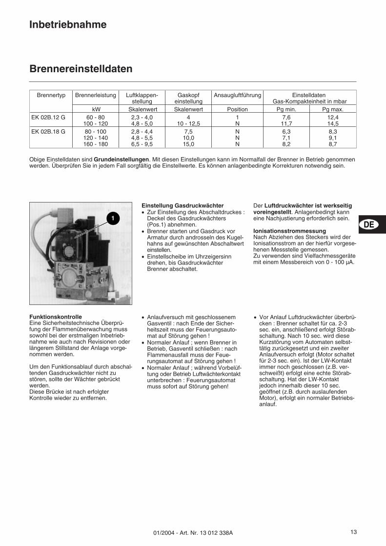
Einstellung Gasdruckwächter� Zur Einstellung des Abschaltdruckes :
Deckel des Gasdruckwächters(Pos.1) abnehmen.
� Brenner starten und Gasdruck vorArmatur durch androsseln des Kugel-hahns auf gewünschten Abschaltwerteinstellen.
� Einstellscheibe im Uhrzeigersinndrehen, bis GasdruckwächterBrenner abschaltet.
Der Luftdruckwächter ist werkseitigvoreingestellt. Anlagenbedingt kanneine Nachjustierung erforderlich sein.
IonisationsstrommessungNach Abziehen des Steckers wird derIonisationsstrom an der hierfür vorgese-henen Messstelle gemessen.Zu verwenden sind Vielfachmessgerätemit einem Messbereich von 0 - 100 µA.
FunktionskontrolleEine Sicherheitstechnische Überprü-fung der Flammenüberwachung musssowohl bei der erstmaligen Inbetrieb-nahme wie auch nach Revisionen oderlängerem Stillstand der Anlage vorge-nommen werden.
Um den Funktionsablauf durch abschal-tenden Gasdruckwächter nicht zustören, sollte der Wächter gebrücktwerden.Diese Brücke ist nach erfolgterKontrolle wieder zu entfernen.
� Anlaufversuch mit geschlossenemGasventil : nach Ende der Sicher-heitszeit muss der Feuerungsauto-mat auf Störung gehen !
� Normaler Anlauf ; wenn Brenner inBetrieb, Gasventil schließen : nachFlammenausfall muss der Feue-rungsautomat auf Störung gehen !
� Normaler Anlauf ; während Vorbelüf-tung oder Betrieb Luftwächterkontaktunterbrechen : Feuerungsautomatmuss sofort auf Störung gehen!
� Vor Anlauf Luftdruckwächter überbrü-cken : Brenner schaltet für ca. 2-3sec. ein, anschließend erfolgt Störab-schaltung. Nach 10 sec. wird dieseKurzstörung vom Automaten selbst-tätig zurückgesetzt und ein zweiterAnlaufversuch erfolgt (Motor schaltetfür 2-3 sec. ein). Ist der LW-Kontaktimmer noch geschlossen (z.B. ver-schweißt) erfolgt eine echte Störab-schaltung. Hat der LW-Kontaktjedoch innerhalb dieser 10 sec.geöffnet (z.B. durch auslaufendenMotor), erfolgt ein normaler Betriebs-anlauf.
Brennertyp Brennerleistung Luftklappen-stellung
Gaskopfeinstellung
Ansaugluftführung EinstelldatenGas-Kompakteinheit in mbar
kW Skalenwert Skalenwert Position Pg min. Pg max.EK 02B.12 G 60 - 80
100 - 1202,3 - 4,04,8 - 5,0
410 - 12,5
1N
7,611,7
12,414,5
EK 02B.18 G 80 - 100120 - 140160 - 180
2,8 - 4,44,8 - 5,56,5 - 9,5
7,510,015,0
NNN
6,37,18,2
8,39,18,7
Obige Einstelldaten sind Grundeinstellungen. Mit diesen Einstellungen kann im Normalfall der Brenner in Betrieb genommenwerden. Überprüfen Sie in jedem Fall sorgfältig die Einstellwerte. Es können anlagenbedingte Korrekturen notwendig sein.
DE
01/2004 - Art. Nr. 13 012 338A14
Service
Wartung
Servicearbeiten an Kessel und Brennerführt ausschließlich der geschulte Hei-zungsfachmann durch. Um eine regelmä-ßige Durchführung der Servicearbeitenzu gewährleisten ist dem Betreiber derAnlage der Abschluss eines Wartungs-vertrages zu empfehlen.
�� Vor Wartung und Reinigungsarbeiten,
Strom abschalten.� Handabsperrventil schließen� Originalersatzteile verwenden.
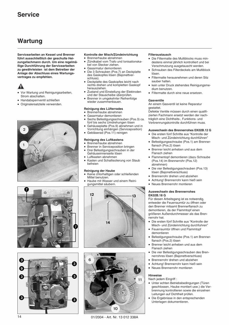
Kontrolle der Misch/Zündeinrichtung� Brennerhaube abnehmen� Zündkabel vom Trafo und Ionisationska-
bel von Stecker ziehen.� Gasarmatur demontieren� Die 3 Schrauben (Pos.7) an Deckplatte
des Gaskopfes lösen (Bajonettver-schluss).
� Deckplatte des Gaskopfes leicht nachrechts drehen und kompletten Gaskopfherausziehen.
� Zustand und Einstellung der Elektrodenund der Stauscheibe überprüfen.
� Brenner in umgekehrter Reihenfolgewieder zusammenbauen.
Reinigung des Lüfterrades� Brennerhaube abnehmen� Gasarmatur demontieren� Sechs Befestigungsschrauben (Pos.3) ca.
fünf bis sechs Umdrehungen lösen� Gehäuseplatte (Pos.9) abnehmen und in
Vorrichtung einhängen (Serviceposition)� Gebläserad (Pos.11) reinigen
Reinigung des Luftkastens� Brennerhaube abnehmen� Brenner in Serviceposition bringen� Drei Befestigungsschrauben in der
Gehäuseinnenseite lösen� Luftkasten abnehmen� Kasten und Schallisolierung von Staub
befreien
Reinigung der Haube� Keine chlorhaltigen oder schleifenden
Mittel benutzen.� Haube mit Wasser und einem Reini-
gungsmittel säubern.
Filteraustausch� Die Filtermatte des Multiblocks muss min-
destens einmal jährlich kontrolliert und beiVerschmutzung ausgetauscht werden.
� Schrauben des Filterdeckels am Multiblocklösen.
� Filtermatte herausnehmen und deren Sitzsauber halten.
� kein unter Druck stehendes Reinigungsme-dium benutzen.
� Filtermatte durch eine neue ersetzen.
GasventileAn einem Gasventil ist keine Reparaturgestattet.Defekte Ventile müssen durch einen qualifi-zierten Fachmann ersetzt werden der nach-träglich eine Dichtheits-, Funktions- undVerbrennungskontrolle durchführen muss.
Auswechseln des Brennerrohes EK02B.12 G� Die ersten fünf Schritte aus “Kontrolle der
Misch- und Zündeinrichtung durchführen”� Befestigungsschraube (Pos.1) am Brenner-
flansch (Pos.2) lösen� Brenner leicht anheben und aus dem
Flansch ziehen� Flammentopf demontieren (dazu Schraube
(Pos.14) im Brennerrohr (Pos.12)abnehmen)
� Die vier Befestigungsschrauben (Pos.13)lösen (Bajonettverschluss)
� Brennerrohr drehen und abziehen� Achtung! Brennerrohr kann hieß sein� Neues Brennerrohr montieren
Auswechseln des BrennerrohesEK02B.18 GFür diesen Arbeitsgang ist es notwendig,entweder die Feuerraumtür zu öffnen oderden Brenner mitsamt Brennerflansch zudemontieren, da der Flammtopf einengrößeren Außendurchmesser als das Bren-nerrohr hat.� Die ersten fünf Schritte aus “Kontrolle der
Misch- und Zündeinrichtung durchfuhren”� Feuerraumtür öffnen und Flammtopf
demontieren� Befestigungsschraube (Pos.1) am Brenner-
flansch (Pos.2) lösen� Brenner leicht anheben und aus dem
Flansch ziehen� Die vier Befestigungsschrauben des Bren-
nerrohres lösen (Bajonettverschluss)� Brennerrohr drehen und abziehen� Achtung! Brennerrohr kann hieß sein� Neues Brennerrohr montieren
HinweiseNach jedem Eingriff :� Unter echten Betriebsbedingungen (Türen
geschlossen, Haube montiert usw.) die Ver-brennung kontrollieren sowie die einzelnenLeitungen auf Dichtheit prüfen.
� Die Ergebnisse in den entsprechendenUnterlagen dokumentieren.
01/2004 - Art. Nr. 13 012 338A 15
Service
Störungsbeseitigung
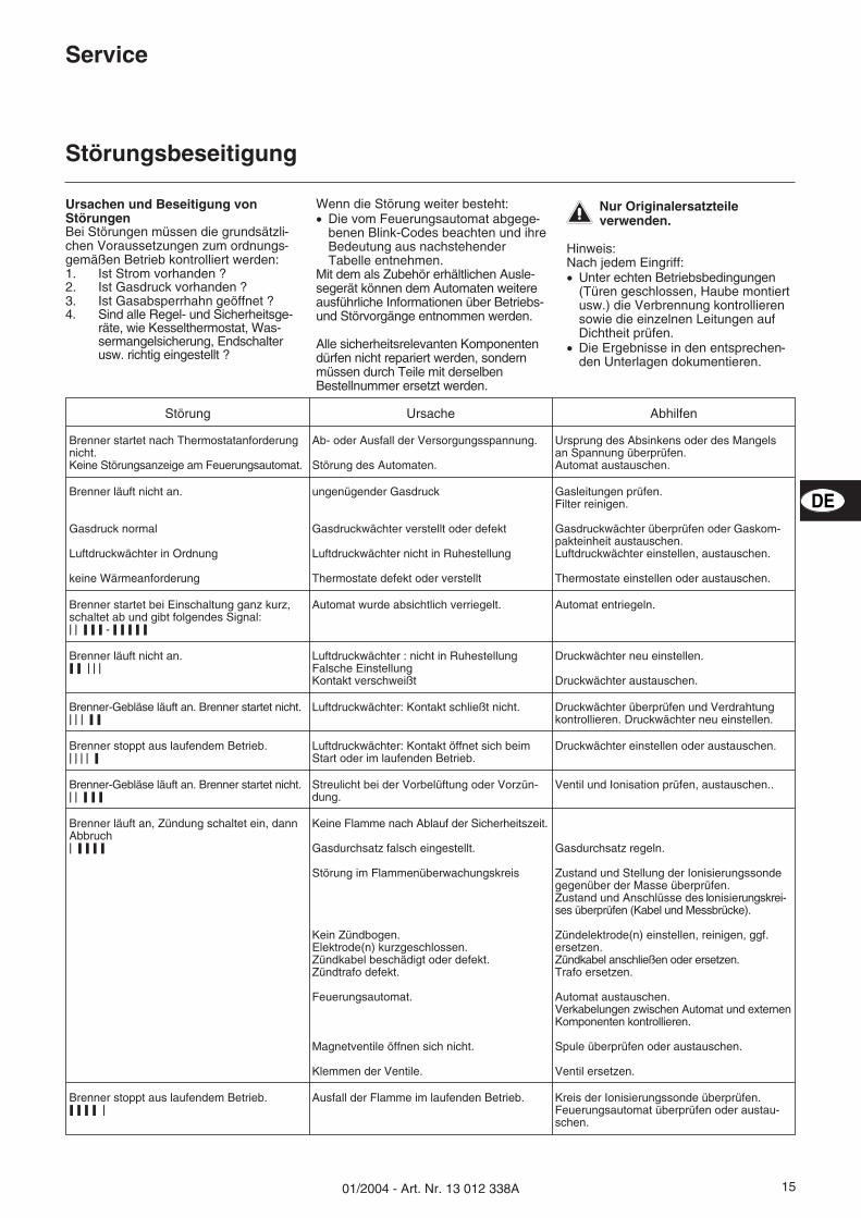
Ursachen und Beseitigung vonStörungenBei Störungen müssen die grundsätzli-chen Voraussetzungen zum ordnungs-gemäßen Betrieb kontrolliert werden:1. Ist Strom vorhanden ?2. Ist Gasdruck vorhanden ?3. Ist Gasabsperrhahn geöffnet ?4. Sind alle Regel- und Sicherheitsge-
räte, wie Kesselthermostat, Was-sermangelsicherung, Endschalterusw. richtig eingestellt ?
Wenn die Störung weiter besteht:� Die vom Feuerungsautomat abgege-
benen Blink-Codes beachten und ihreBedeutung aus nachstehenderTabelle entnehmen.
Mit dem als Zubehör erhältlichen Ausle-segerät können dem Automaten weitereausführliche Informationen über Betriebs-und Störvorgänge entnommen werden.
Alle sicherheitsrelevanten Komponentendürfen nicht repariert werden, sondernmüssen durch Teile mit derselbenBestellnummer ersetzt werden.
�Nur Originalersatzteileverwenden.
Hinweis:Nach jedem Eingriff:� Unter echten Betriebsbedingungen
(Türen geschlossen, Haube montiertusw.) die Verbrennung kontrollierensowie die einzelnen Leitungen aufDichtheit prüfen.
� Die Ergebnisse in den entsprechen-den Unterlagen dokumentieren.
Störung Ursache Abhilfen
Brenner startet nach Thermostatanforderungnicht.Keine Störungsanzeige am Feuerungsautomat.
Ab- oder Ausfall der Versorgungsspannung.
Störung des Automaten.
Ursprung des Absinkens oder des Mangelsan Spannung überprüfen.Automat austauschen.
Brenner läuft nicht an.
Gasdruck normal
Luftdruckwächter in Ordnung
keine Wärmeanforderung
ungenügender Gasdruck
Gasdruckwächter verstellt oder defekt
Luftdruckwächter nicht in Ruhestellung
Thermostate defekt oder verstellt
Gasleitungen prüfen.Filter reinigen.
Gasdruckwächter überprüfen oder Gaskom-pakteinheit austauschen.Luftdruckwächter einstellen, austauschen.
Thermostate einstellen oder austauschen.
Brenner startet bei Einschaltung ganz kurz,schaltet ab und gibt folgendes Signal:���������� - ������� �
Automat wurde absichtlich verriegelt. Automat entriegeln.
Brenner läuft nicht an.��� �����
Luftdruckwächter : nicht in RuhestellungFalsche EinstellungKontakt verschweißt
Druckwächter neu einstellen.
Druckwächter austauschen.
Brenner-Gebläse läuft an. Brenner startet nicht.��� ������
Luftdruckwächter: Kontakt schließt nicht. Druckwächter überprüfen und Verdrahtungkontrollieren. Druckwächter neu einstellen.
Brenner stoppt aus laufendem Betrieb.����������
Luftdruckwächter: Kontakt öffnet sich beimStart oder im laufenden Betrieb.
Druckwächter einstellen oder austauschen.
Brenner-Gebläse läuft an. Brenner startet nicht.������ ���
Streulicht bei der Vorbelüftung oder Vorzün-dung.
Ventil und Ionisation prüfen, austauschen..
Brenner läuft an, Zündung schaltet ein, dannAbbruch�������� �
Keine Flamme nach Ablauf der Sicherheitszeit.
Gasdurchsatz falsch eingestellt.
Störung im Flammenüberwachungskreis
Kein Zündbogen.Elektrode(n) kurzgeschlossen.Zündkabel beschädigt oder defekt.Zündtrafo defekt.
Feuerungsautomat.
Magnetventile öffnen sich nicht.
Klemmen der Ventile.
Gasdurchsatz regeln.
Zustand und Stellung der Ionisierungssondegegenüber der Masse überprüfen.Zustand und Anschlüsse des Ionisierungskrei-ses überprüfen (Kabel und Messbrücke).
Zündelektrode(n) einstellen, reinigen, ggf.ersetzen.Zündkabel anschließen oder ersetzen.Trafo ersetzen.
Automat austauschen.Verkabelungen zwischen Automat und externenKomponenten kontrollieren.
Spule überprüfen oder austauschen.
Ventil ersetzen.
Brenner stoppt aus laufendem Betrieb.����� � �
Ausfall der Flamme im laufenden Betrieb. Kreis der Ionisierungssonde überprüfen.Feuerungsautomat überprüfen oder austau-schen.
DE
01/2004 - Art. Nr. 13 012 338A16
Overview
Contents
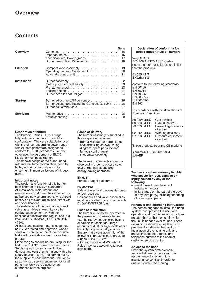
SeiteOverview Contents. . . . . . . . . . . . . . . . . . . . . . . . . 16
Important notes . . . . . . . . . . . . . . . . . . . . . 16Technical data, Power graphs . . . . . . . . . . . . . 17Burner description, Dimensions . . . . . . . . . . . . . 18
Function Compact valve assembly . . . . . . . . . . . . . . . . 19Operating function, Safety function . . . . . . . . . . . 20Automatic control unit . . . . . . . . . . . . . . . . . . 21
Installation Burner assembly . . . . . . . . . . . . . . . . . . . . 22Gas supply,Electrical supply . . . . . . . . . . . . . . 23Pre-startup check . . . . . . . . . . . . . . . . . . . . 23Testing/Setting . . . . . . . . . . . . . . . . . . . . . 24Burner head for natural gas . . . . . . . . . . . . . . . 24
Startup Burner adjustment/Airflow control . . . . . . . . . . . . 25Burner adjustment/Setting the Compact Gas Unit. . . . 26Burner adjustment data . . . . . . . . . . . . . . . . . 27
Servicing Maintenance . . . . . . . . . . . . . . . . . . . . . . 28Troubleshooting . . . . . . . . . . . . . . . . . . . . . 29
Description of burnerThe burners EK02B... G is 1-stage,fully-automatic burners in monoblocconfiguration. They are suitable for use,within their corresponding power range,with all heat generators designed toconform to EN303 standards. For anyother use, the agreement of ELCOKlöckner must be asked for.The special design of the burner head,with internal fume recirculation, permitshighly efficient combustion - whileensuring minimum emissions of nitrogenoxide.
Important notesThe design and function of this burnerboth conform to EN 676 standards.All installation, initial-startup andmaintenance work must be carried out byauthorised service engineers, who shouldobserve all relevant guidelines, directivesand specifications.The installation of the gas conduits andvalve assemblies should likewise becarried out in conformity with theapplicable directives and regulations (e.g.DVGW-TRGI 1986/96 ; TRF 1988 ; DIN4756).All seals and sealing material used mustbe DVGW tested and approved. Checkseals and connection points for possibleleaks with a suitable non-corrosive foamproduct.Bleed the gas conduit before using for thefirst time. DO NOT bleed via the furnace.Servicing work on switches, limitingdevices and control units - along with othersafety devices - MUST be carried out bythe supplier of each individual item, or byits authorised service engineers. Originalparts may only be replaced by anauthorised service engineer.
Scope of deliveryThe burner assembly is supplied inthree separate packages:� Burner with burner head, flange
seal and fixing screws, wiringdiagram, spare parts list andfurnace control panel.
� Gas-valve assembly.
The following standards should beobserved in order to ensure safe,environmentally sound andenergy-saving operation:
EN 676Forced-draught gas burner
EN 60335-2Safety of electrical devices designedfor domestic useGas conduits and valve assembliesmust be installed in accordance withDVGW-TVR/TRGI (gas).
Place of installationThe burner must not be operated inthe presence of corrosive fumes(e.g. hairspray, tetrachloroethyleneor carbon tetrachloride), largeamounts of dust, or high levels of airhumidity (e.g. in laundry rooms).Ensure that a ventilation inlet of thefollowing characteristics is provided:– up to 50kW: 150cm²– for each additional kW: +2cm²Rules may vary according to locallegislation.
We can accept no warranty liabilitywhatsoever for loss, damage orinjury caused by any of thefollowing:– unauthorised use - Incorrect
installation and/or– initial startup on the part of the buyer
or any third party, including the fittingof non-original parts.
Handover and operating instructionsThe person engaged to install the firingsystem must provide the user withoperation and maintenance instructionsno later than at the moment in whichthe unit is handed over for use. Theseinstructions should be displayed in aprominent location at the point ofinstallation of the heating unit, andshould include the address andtelephone number of the nearestcustomer service centre.
Advice to the userHave the system professionallyserviced at least once a year. It isrecommended to enter into amaintenance contract in order toensure trouble-free running.
Declaration of conformity forforced-draught fuel-oil burners
We, CEB, ofF-74106 ANNEMASSE Cedexdeclare under our sole responsibilitythat the products
EK02B.12 GEK02B.18 G
conform to the following standardsEN 50165EN 55014EN 60335EN 60555-2EN 60555-3EN 267
In accordance with the stipulations ofEuropean Directives
89 / 396 /EEC Gas devices89 / 336 /EEC EMC-directive73 / 23 /EEC Low-voltage devices
directive92 / 42 /EEC Working efficiency97 / 23 /EEC Pressure equipment
directive
These products bear the CE marking
Annemasse, January 2004J.HAEP
1701/2004 - Art. Nr. 13 012 338A
Overview
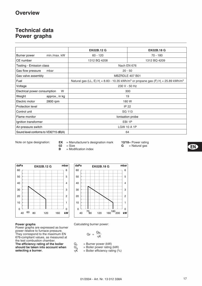
Technical dataPower graphs
Note on type designation: EK = Manufacturer's designation mark02 = SizeB = Modification index
12/18= Power ratingG = Natural gas
daPa mbar
kW600
10
20
30
40
50
60
40 80 120 160
0
1
2
3
4
5
6EK02B.12 G daPa mbar
kW18070
0
10
20
30
40
50
60
40 80 120 160 200
0
1
2
3
4
5
6EK02B.18 G
EK02B.12 G EK02B.18 G
Burner power min./max. kW 60 - 120 70 - 180
CE number 1312 BQ 4208 1312 BQ 4209
Testing - Emission class Nach EN 676
Gas flow pressure mbar 20 - 50
Gas valve assembly MBZRDLE 407 B01
Fuel Natural gas (LL, E) Hi = 8.83 - 10.35 kWh/m3 or propane gas (F) Hi = 25.89 kWh/m3
Voltage 230 V - 50 Hz
Electrical power consumption W 300
Weight approx., in kg 19
Electric motor 2800 rpm 180 W
Protection level IP 22
Control unit SG 113
Flame monitor Ionisation probe
Ignition transformer EBI 1P
Air-pressure switch LGW 10 A 1P
Sound level conforms to VDI2715 dB(A) 64
EN
Calculating burner power:
QF = Burner power (kW)QN = Boiler power rating (kW)�K = Boiler efficiency rating (%)
Power graphsPower graphs are expressed as burnerpower relative to furnace pressure.They correspond to the maximum EN676-compliant values, as measured atthe test combustion chamber.The efficiency rating of the boilershould be taken into account whenselecting a burner.
QNQF =�K
01/2004 - Art. Nr. 13 012 338A18
Overview
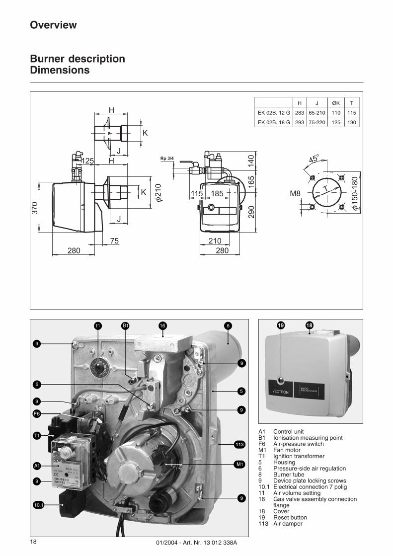
Burner descriptionDimensions
115
125
H
H
J
J
Rp 3/4
37
0
280
75
φ2
10
K
210
28029
0 φ1
50
-18
0
M8
45°
T
K
185
16
514
0
A1 Control unitB1 Ionisation measuring pointF6 Air-pressure switchM1 Fan motorT1 Ignition transformer5 Housing6 Pressure-side air regulation8 Burner tube9 Device plate locking screws10.1 Electrical connection 7 polig11 Air volume setting16 Gas valve assembly connection
flange18 Cover19 Reset button113 Air damper
H J ØK T
EK 02B. 12 G 283 65-210 110 115
EK 02B. 18 G 293 75-220 125 130
1901/2004 - Art. Nr. 13 012 338A
Function
Compact valve assembly
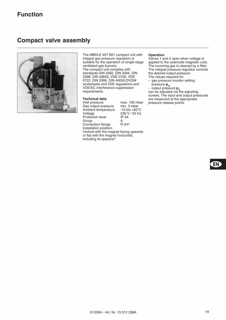
OperationValves 1 and 2 open when voltage isapplied to the solenoids magnetic coils.The incoming gas is cleaned by a filter.The integral pressure regulator controlsthe desired output pressure.The values required for– gas pressure monitor setting
pressure pW– output pressure pGcan be adjusted via the adjustingscrews. The input and output pressuresare measured at the appropriatepressure release points.
The MBDLE 407 B01 compact unit withintegral gas pressure regulation issuitable for the operation of single-stageventilated gas burners.The compact unit complies withstandards DIN 3392, DIN 3394, DIN3398, DIN 43650, VDE 0700, VDE0722, DIN 3386, DIN 40050,DVGWworksheets and VDE regulations andVDE/EC interference suppressionrequirements.
Technical dataInlet pressure max. 100 mbarGas output pressure min. 3 mbarAmbient temperature -10 bis +60°CVoltage 230 V / 50 HzProtection level IP 54Group AConnection flange R 3/4“Installation position:Vertical with the magnet facing upwardsor flat with the magnet horizontal,including its spacers?
EN
01/2004 - Art. Nr. 13 012 338A20
Function
Operating functionSafety function
Compact valve assembly
Function description– Control thermostat indicates heat
requirement.– The operating program of the control
system starts up if the air pressureswitch contact is in its idle position,and is receiving a signal from the gaspressure switch, indicating that thereis sufficient pressure.
– Burner motor running.– Pre-ventilation time 54 s.
During the pre-ventilation period:– fan pressure is monitored,– the furnace is monitored for flame
signals.
After the pre-ventilation period hasexpired:– the ignition system is activated,– the main valve and safety valve are
opened.– Burner start-up
MonitoringThe flame is monitored by an ionisationprobe. The insulated probe is fitted tothe gas head and leads through theturbulator to the flame zone. Note thatthe probe MUST NOT be allowed tocome into electrical contact withearthed (grounded) components.
If a short circuit occurs between theprobe and the burner, the burnerswitches to malfunction mode.
When the burner is in operation, thereis an ionised zone within the gas flame,which allows a rectified current to flowfrom the probe to the burner.The ionisation current must not dropbelow 8 µA.
Safety functions– If no flame appears when the burner
starts up (release of gas), a safetyperiod of up to three seconds elapsesbefore the burner shuts down and thegas valve closes.
– If the flame goes out duringoperation, the gas supply cuts outwithin one second and the controlunit triggers an emergency shutdown.
– If there is insufficient air during thepre-ventilation phase, the burner willnot start, and an emergencyshutdown takes place.
– An emergency shutdown likewisetakes place if there is insufficient airduring operation.
– The burner will not start if the gassupply is insufficient. If the gassupply drops during operation, thegas valve closes and the burnershuts down. This does not result inan emergency shutdown. The burnerrestarts automatically when gaspressure returns to its correct level.
NoteFire regulations normally stipulate thatgas-fired devices must be fitted with athermally-triggered shutoff valve.
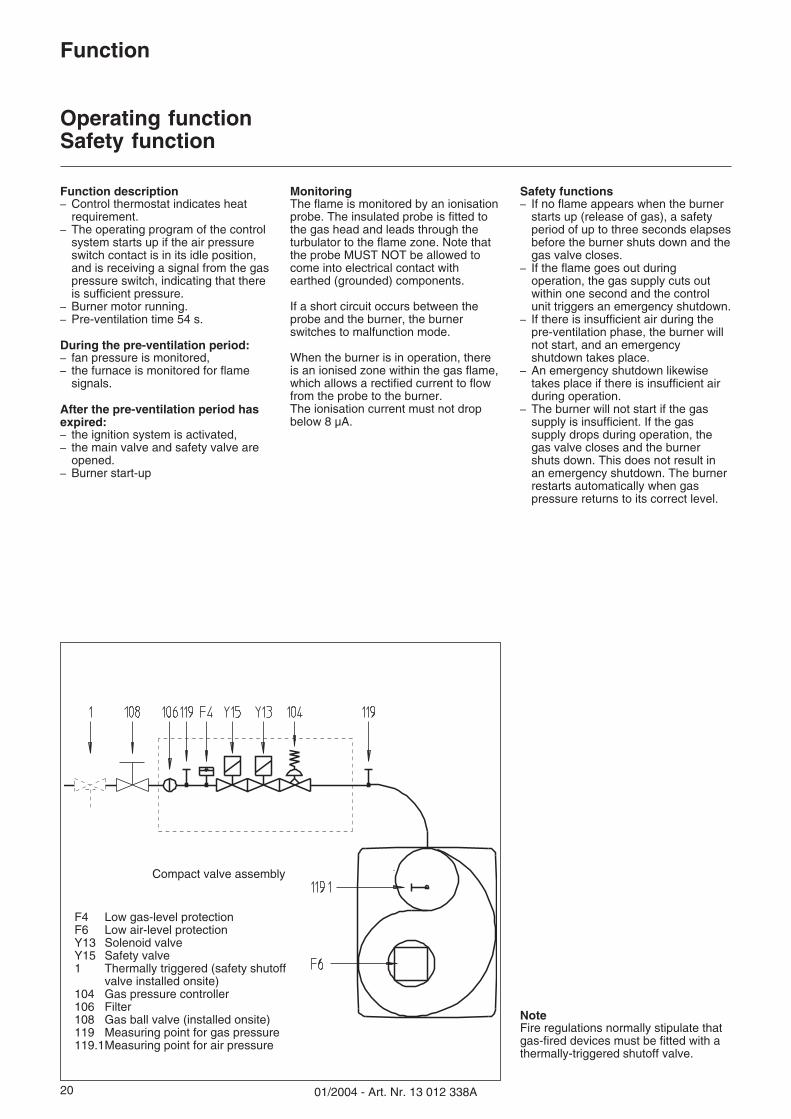
F4 Low gas-level protectionF6 Low air-level protectionY13 Solenoid valveY15 Safety valve1 Thermally triggered (safety shutoff
valve installed onsite)104 Gas pressure controller106 Filter108 Gas ball valve (installed onsite)119 Measuring point for gas pressure119.1Measuring point for air pressure
2101/2004 - Art. Nr. 13 012 338A
Function
Automatic Control Unit SG 113
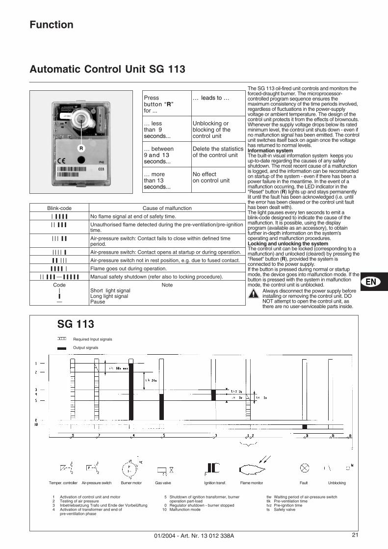
1 Activation of control unit and motor2 Testing of air pressure3 Inbetriebsetzung Trafo und Ende der Vorbelüftung4 Activation of transformer and end of
pre-ventilation phase
5 Shutdown of ignition transformer, burneroperation part-load
0 Regulator shutdown - burner stopped10 Malfunction mode
tlw Waiting period of air-pressure switchtlk Pre-ventilation timetvz Pre-ignition timets Safety valve
EN
Blink-code Cause of malfunction
���������� No flame signal at end of safety time.
��� ����� Unauthorised flame detected during the pre-ventilation/pre-ignitiontime.
����� ��� Air-pressure switch: Contact fails to close within defined timeperiod.
��� ��� � Air-pressure switch: Contact opens at startup or during operation.
��� ����� Air-pressure switch not in rest position, e.g. due to fused contact.
������� � Flame goes out during operation.
���������� — ����� ��� Manual safety shutdown (refer also to locking procedure).
Code��
—
NoteShort light signalLong light signalPause
Pressbutton “R”for ...
… leads to …
… lessthan 9seconds...
Unblocking orblocking of thecontrol unit
… between9 and 13seconds...
Delete the statisticsof the control unit
… morethan 13seconds...
No effecton control unit
The SG 113 oil-fired unit controls and monitors theforced-draught burner. The microprocessor-controlled program sequence ensures themaximum consistency of the time periods involved,regardless of fluctuations in the power-supplyvoltage or ambient temperature. The design of thecontrol unit protects it from the effects of brownouts.Whenever the supply voltage drops below its ratedminimum level, the control unit shuts down - even ifno malfunction signal has been emitted. The controlunit switches itself back on again once the voltagehas returned to normal levels.Information systemThe built-in visual information system keeps youup-to-date regarding the causes of any safetyshutdown. The most recent cause of a malfunctionis logged, and the information can be reconstructedon startup of the system - even if there has been apower failure in the meantime. In the event of amalfunction occurring, the LED indicator in the"Reset" button (R) lights up and stays permanentlylit until the fault has been acknowledged (i.e. untilthe error has been cleared or the control unit faulthas been dealt with).The light pauses every ten seconds to emit ablink-code designed to indicate the cause of themalfunction. It is possible, using the displayprogram (available as an accessory), to obtainfurther in-depth information on the system'soperating and malfunction procedures.Locking and unlocking the systemThe control unit can be locked (corresponding to amalfunction) and unlocked (cleared) by pressing the"Reset" button (R), provided the system isconnected to the power supply.If the button is pressed during normal or startupmode, the device goes into malfunction mode. If thebutton is pressed with the system in malfunctionmode, the control unit is unblocked.
�Always disconnect the power supply beforeinstalling or removing the control unit. DONOT attempt to open the control unit, asthere are no user-serviceable parts inside.
Required Input signals
Output signals
Temper. controller Air-pressure switch Burner motor Gas valve Ignition transf. Flame monitor Fault Unblocking
01/2004 - Art. Nr. 13 012 338A22
Installation
Burner assembly
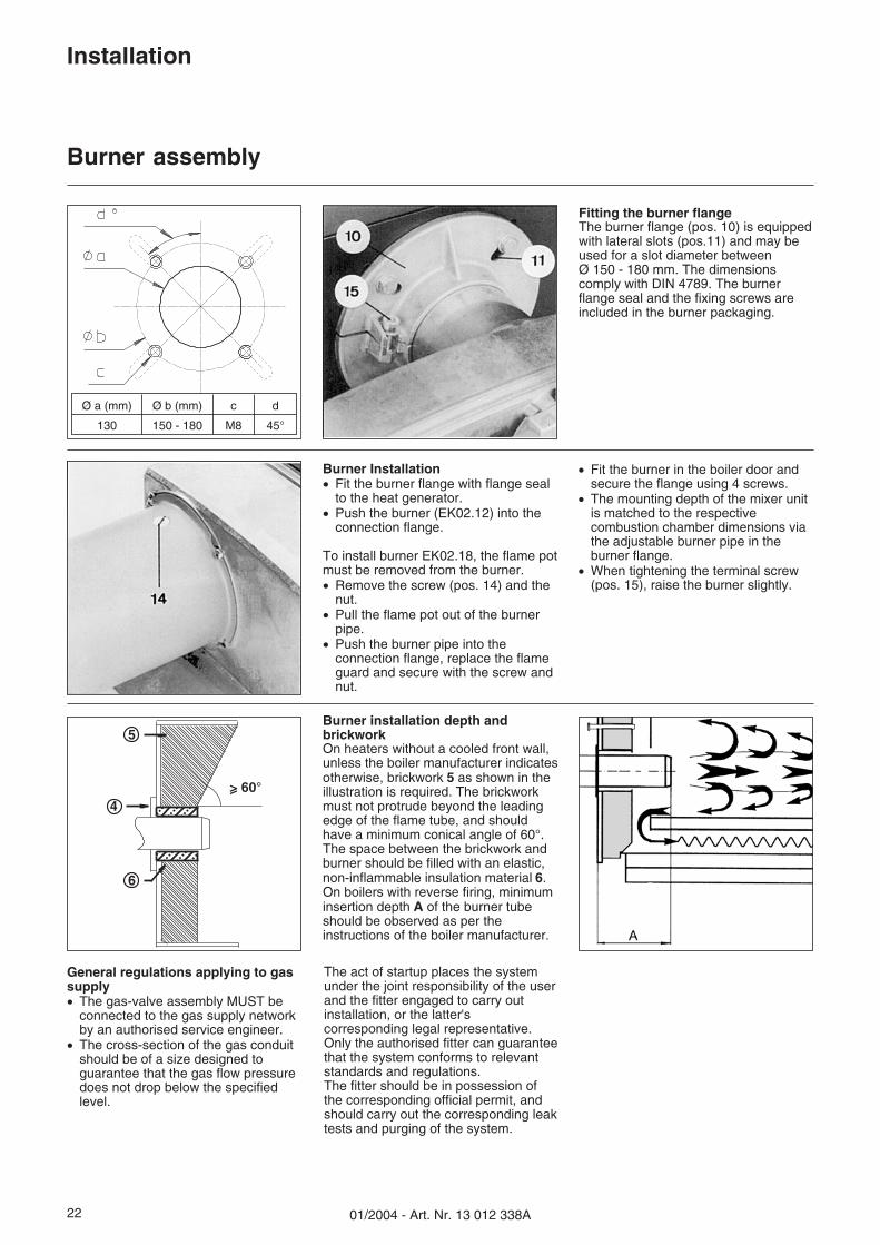
Fitting the burner flangeThe burner flange (pos. 10) is equippedwith lateral slots (pos.11) and may beused for a slot diameter betweenØ 150 - 180 mm. The dimensionscomply with DIN 4789. The burnerflange seal and the fixing screws areincluded in the burner packaging.
Burner installation depth andbrickworkOn heaters without a cooled front wall,unless the boiler manufacturer indicatesotherwise, brickwork 5 as shown in theillustration is required. The brickworkmust not protrude beyond the leadingedge of the flame tube, and shouldhave a minimum conical angle of 60°.The space between the brickwork andburner should be filled with an elastic,non-inflammable insulation material 6.On boilers with reverse firing, minimuminsertion depth A of the burner tubeshould be observed as per theinstructions of the boiler manufacturer.
5
4
6
Ø a (mm) Ø b (mm) c d
130 150 - 180 M8 45°
General regulations applying to gassupply� The gas-valve assembly MUST be
connected to the gas supply networkby an authorised service engineer.
� The cross-section of the gas conduitshould be of a size designed toguarantee that the gas flow pressuredoes not drop below the specifiedlevel.
The act of startup places the systemunder the joint responsibility of the userand the fitter engaged to carry outinstallation, or the latter'scorresponding legal representative.Only the authorised fitter can guaranteethat the system conforms to relevantstandards and regulations.The fitter should be in possession ofthe corresponding official permit, andshould carry out the corresponding leaktests and purging of the system.
Burner Installation� Fit the burner flange with flange seal
to the heat generator.� Push the burner (EK02.12) into the
connection flange.
To install burner EK02.18, the flame potmust be removed from the burner.� Remove the screw (pos. 14) and the
nut.� Pull the flame pot out of the burner
pipe.� Push the burner pipe into the
connection flange, replace the flameguard and secure with the screw andnut.
� Fit the burner in the boiler door andsecure the flange using 4 screws.
� The mounting depth of the mixer unitis matched to the respectivecombustion chamber dimensions viathe adjustable burner pipe in theburner flange.
� When tightening the terminal screw(pos. 15), raise the burner slightly.
2301/2004 - Art. Nr. 13 012 338A
Installation
Gas supplyElectrical supplyPre-startup check
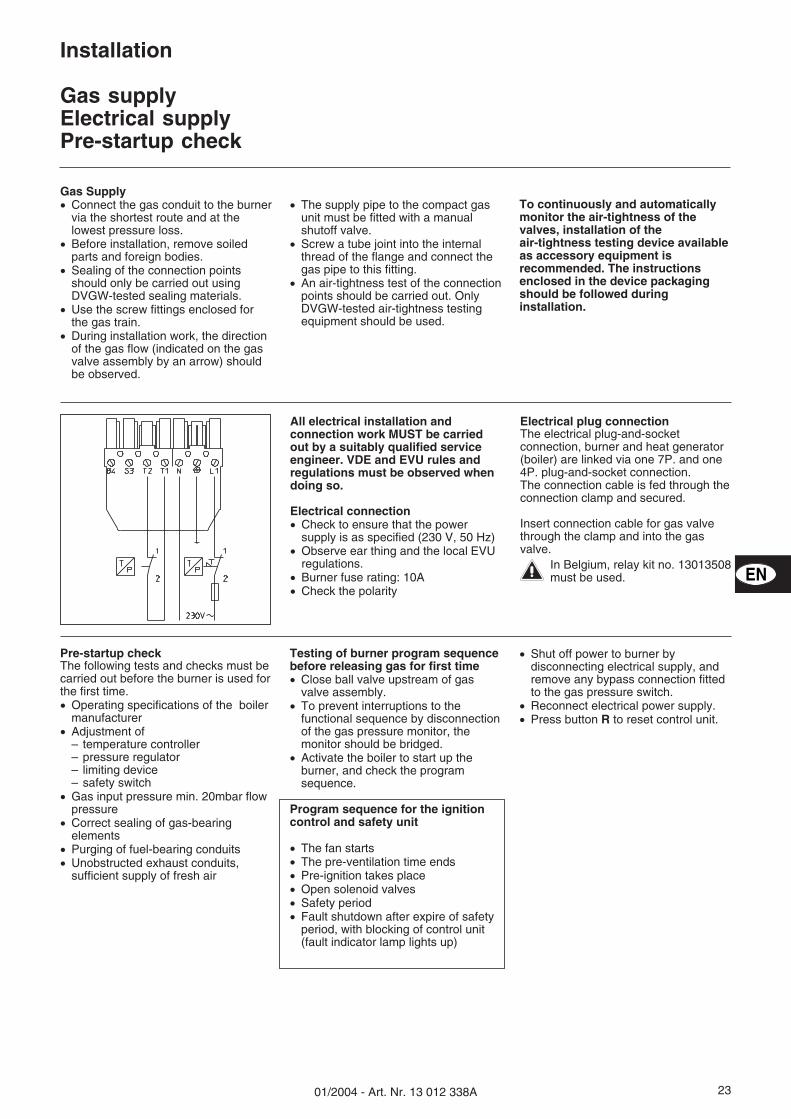
All electrical installation andconnection work MUST be carriedout by a suitably qualified serviceengineer. VDE and EVU rules andregulations must be observed whendoing so.
Electrical connection� Check to ensure that the power
supply is as specified (230 V, 50 Hz)� Observe ear thing and the local EVU
regulations.� Burner fuse rating: 10A� Check the polarity
Electrical plug connectionThe electrical plug-and-socketconnection, burner and heat generator(boiler) are linked via one 7P. and one4P. plug-and-socket connection.The connection cable is fed through theconnection clamp and secured.
Insert connection cable for gas valvethrough the clamp and into the gasvalve.
�In Belgium, relay kit no. 13013508must be used.
Gas Supply� Connect the gas conduit to the burner
via the shortest route and at thelowest pressure loss.
� Before installation, remove soiledparts and foreign bodies.
� Sealing of the connection pointsshould only be carried out usingDVGW-tested sealing materials.
� Use the screw fittings enclosed forthe gas train.
� During installation work, the directionof the gas flow (indicated on the gasvalve assembly by an arrow) shouldbe observed.
� The supply pipe to the compact gasunit must be fitted with a manualshutoff valve.
� Screw a tube joint into the internalthread of the flange and connect thegas pipe to this fitting.
� An air-tightness test of the connectionpoints should be carried out. OnlyDVGW-tested air-tightness testingequipment should be used.
To continuously and automaticallymonitor the air-tightness of thevalves, installation of theair-tightness testing device availableas accessory equipment isrecommended. The instructionsenclosed in the device packagingshould be followed duringinstallation.
Pre-startup checkThe following tests and checks must becarried out before the burner is used forthe first time.� Operating specifications of the boiler
manufacturer� Adjustment of
– temperature controller– pressure regulator– limiting device– safety switch
� Gas input pressure min. 20mbar flowpressure
� Correct sealing of gas-bearingelements
� Purging of fuel-bearing conduits� Unobstructed exhaust conduits,
sufficient supply of fresh air
Testing of burner program sequencebefore releasing gas for first time� Close ball valve upstream of gas
valve assembly.� To prevent interruptions to the
functional sequence by disconnectionof the gas pressure monitor, themonitor should be bridged.
� Activate the boiler to start up theburner, and check the programsequence.
Program sequence for the ignitioncontrol and safety unit
� The fan starts� The pre-ventilation time ends� Pre-ignition takes place� Open solenoid valves� Safety period� Fault shutdown after expire of safety
period, with blocking of control unit(fault indicator lamp lights up)
� Shut off power to burner bydisconnecting electrical supply, andremove any bypass connection fittedto the gas pressure switch.
� Reconnect electrical power supply.� Press button R to reset control unit.
EN
01/2004 - Art. Nr. 13 012 338A24
Installation
Testing / SettingBurner head for natural gas
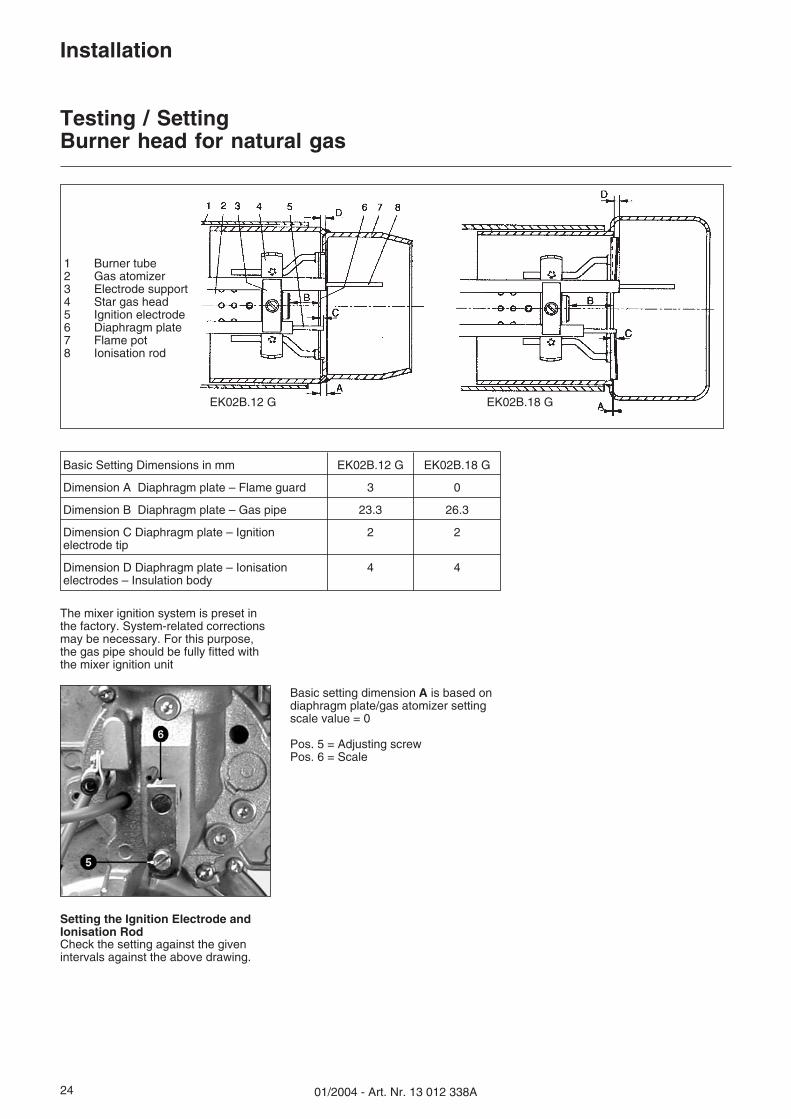
Basic Setting Dimensions in mm EK02B.12 G EK02B.18 G
Dimension A Diaphragm plate – Flame guard 3 0
Dimension B Diaphragm plate – Gas pipe 23.3 26.3
Dimension C Diaphragm plate – Ignitionelectrode tip
2 2
Dimension D Diaphragm plate – Ionisationelectrodes – Insulation body
4 4
EK02B.12 G EK02B.18 G
1 Burner tube2 Gas atomizer3 Electrode support4 Star gas head5 Ignition electrode6 Diaphragm plate7 Flame pot8 Ionisation rod
The mixer ignition system is preset inthe factory. System-related correctionsmay be necessary. For this purpose,the gas pipe should be fully fitted withthe mixer ignition unit
Basic setting dimension A is based ondiaphragm plate/gas atomizer settingscale value = 0
Pos. 5 = Adjusting screwPos. 6 = Scale
Setting the Ignition Electrode andIonisation RodCheck the setting against the givenintervals against the above drawing.
2501/2004 - Art. Nr. 13 012 338A
Startup
Burner adjustment / Air flow control
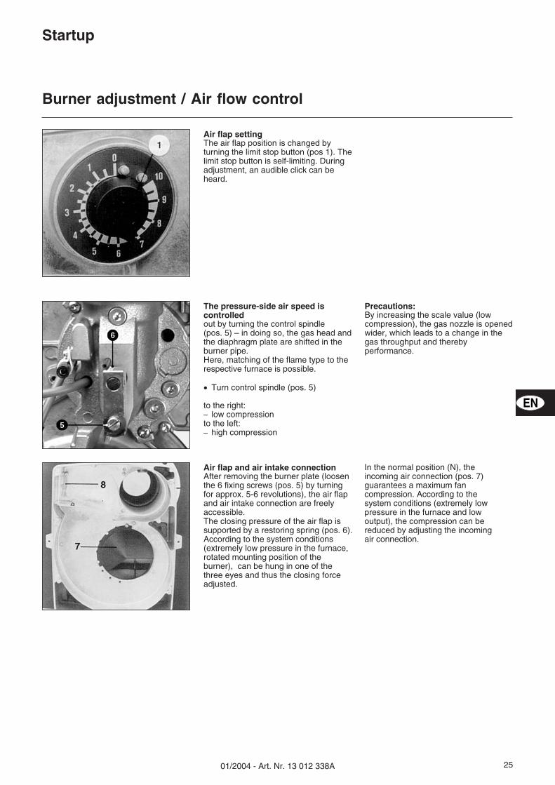
Air flap settingThe air flap position is changed byturning the limit stop button (pos 1). Thelimit stop button is self-limiting. Duringadjustment, an audible click can beheard.
Air flap and air intake connectionAfter removing the burner plate (loosenthe 6 fixing screws (pos. 5) by turningfor approx. 5-6 revolutions), the air flapand air intake connection are freelyaccessible.The closing pressure of the air flap issupported by a restoring spring (pos. 6).According to the system conditions(extremely low pressure in the furnace,rotated mounting position of theburner), can be hung in one of thethree eyes and thus the closing forceadjusted.
In the normal position (N), theincoming air connection (pos. 7)guarantees a maximum fancompression. According to thesystem conditions (extremely lowpressure in the furnace and lowoutput), the compression can bereduced by adjusting the incomingair connection.
The pressure-side air speed iscontrolledout by turning the control spindle(pos. 5) – in doing so, the gas head andthe diaphragm plate are shifted in theburner pipe.Here, matching of the flame type to therespective furnace is possible.
� Turn control spindle (pos. 5)
to the right:– low compressionto the left:– high compression
Precautions:By increasing the scale value (lowcompression), the gas nozzle is openedwider, which leads to a change in thegas throughput and therebyperformance.
EN
01/2004 - Art. Nr. 13 012 338A26
Startup
Burner adjustment / Setting the Compact Gas Unit
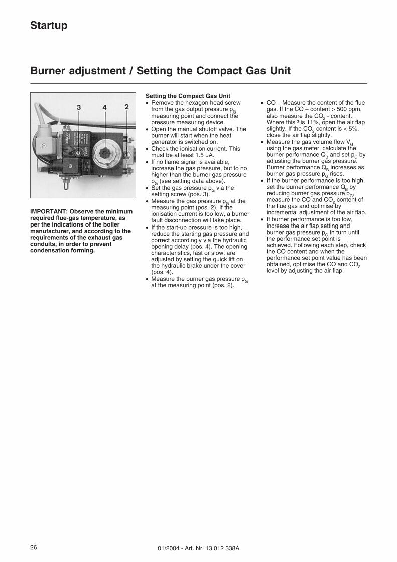
IMPORTANT: Observe the minimumrequired flue-gas temperature, asper the indications of the boilermanufacturer, and according to therequirements of the exhaust gasconduits, in order to preventcondensation forming.
Setting the Compact Gas Unit� Remove the hexagon head screw
from the gas output pressure pGmeasuring point and connect thepressure measuring device.
� Open the manual shutoff valve. Theburner will start when the heatgenerator is switched on.
� Check the ionisation current. Thismust be at least 1.5 µA.
� If no flame signal is available,increase the gas pressure, but to nohigher than the burner gas pressurepG (see setting data above).
� Set the gas pressure pG via thesetting screw (pos. 3).
� Measure the gas pressure pG at themeasuring point (pos. 2). If theionisation current is too low, a burnerfault disconnection will take place.
� If the start-up pressure is too high,reduce the starting gas pressure andcorrect accordingly via the hydraulicopening delay (pos. 4). The openingcharacteristics, fast or slow, areadjusted by setting the quick lift onthe hydraulic brake under the cover(pos. 4).
� Measure the burner gas pressure pGat the measuring point (pos. 2).
� CO – Measure the content of the fluegas. If the CO – content > 500 ppm,also measure the CO2 - content.Where this ³ is 11%, open the air flapslightly. If the CO2 content is < 5%,close the air flap slightly.
� Measure the gas volume flow VGusing the gas meter, calculate theburner performance QB and set pG byadjusting the burner gas pressure.Burner performance QB increases asburner gas pressure pG rises.
� If the burner performance is too high,set the burner performance QB byreducing burner gas pressure pG,measure the CO and CO2 content ofthe flue gas and optimise byincremental adjustment of the air flap.
� If burner performance is too low,increase the air flap setting andburner gas pressure pG in turn untilthe performance set point isachieved. Following each step, checkthe CO content and when theperformance set point value has beenobtained, optimise the CO and CO2level by adjusting the air flap.
2701/2004 - Art. Nr. 13 012 338A
Startup
Burner adjustment data
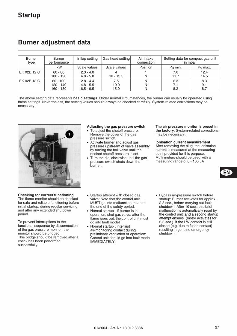
Adjusting the gas pressure switch� To adjust the shutoff pressure:
Remove the cover of the gaspressure switch.
� Activate burner and adjust gaspressure upstream of valve assemblyby turning the ball valve until thedesired shutoff pressure is set.
� Turn the dial clockwise until the gaspressure switch shuts down theburner.
The air pressure monitor is preset inthe factory. System-related correctionsmay be necessary.
Ionisation current measurementAfter removing the plug, the ionisationcurrent is measured at the measuringpoint provided for this purpose.Multi meters should be used with ameasuring range of 0 - 100 µA
Checking for correct functioningThe flame-monitor should be checkedfor safe and reliable functioning beforeinitial startup, during regular servicingand after any extended shutdownperiod.
To prevent interruptions to thefunctional sequence by disconnectionof the gas pressure monitor, themonitor should be bridged.This bridge should be removed after acheck has been performedsuccessfully.
� Startup attempt with closed gasvalve: Note that the control unitMUST go into malfunction mode atthe end of the safety period.
� Normal startup - if burner is inoperation, shut gas valve: after theflame goes out, the control unit mustgo into fault mode!
� Normal startup ; interruptair-monitoring contact duringpreliminary ventilation or operation:Control unit should go into fault modeIMMEDIATELY.
� Bypass air-pressure switch beforestartup: Burner activates for approx.2-3 sec., before carrying out faultshutdown. After 10 sec., this briefmalfunction is automatically reset bythe control unit, and a second startupattempt ensues (motor activates for2-3 sec.). If the LW contact is stillclosed (e.g. due to fused contact)resulting in genuine emergencyshutdown.
Burnertype
Burnerperformance
ir flap setting Gas head setting Air intakeconnection
Setting data for compact gas unitin mbar
kW Scale values Scale values Position Pg min. Pg max.EK 02B.12 G 60 - 80
100 - 1202.3 - 4.04.8 - 5.0
410 - 12.5
1N
7.611.7
12.414.5
EK 02B.18 G 80 - 100120 - 140160 - 180
2.8 - 4.44.8 - 5.56.5 - 9.5
7.510.015.0
NNN
6.37.18.2
8.39.18.7
The above setting data represents basic settings. Under normal circumstances, the burner can usually be operated usingthese settings. Nevertheless, the setting values should always be checked carefully. System-related corrections may benecessary.
EN
01/2004 - Art. Nr. 13 012 338A28
Servicing
Maintenance
All boiler and burner servicing workshould be carried out by anappropriately trained heating servicespecialist. It is recommended toenter into a maintenance contract inorder to ensure that servicing iscarried out at the intervalsprescribed.
�� Shut down the power supply
BEFORE carrying out servicing orcleaning work of any kind.
� Close ball valve.� Use only original spare parts.
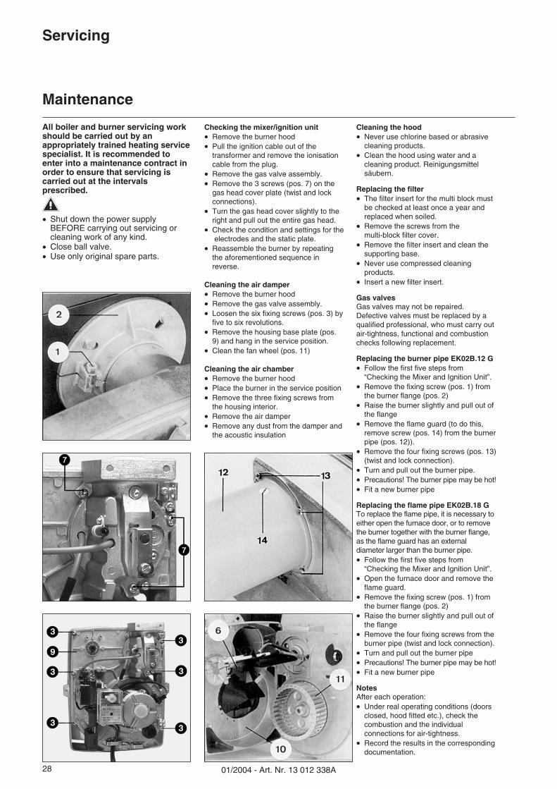
Checking the mixer/ignition unit� Remove the burner hood� Pull the ignition cable out of the
transformer and remove the ionisationcable from the plug.
� Remove the gas valve assembly.� Remove the 3 screws (pos. 7) on the
gas head cover plate (twist and lockconnections).
� Turn the gas head cover slightly to theright and pull out the entire gas head.
� Check the condition and settings for theelectrodes and the static plate.
� Reassemble the burner by repeatingthe aforementioned sequence inreverse.
Cleaning the air damper� Remove the burner hood� Remove the gas valve assembly.� Loosen the six fixing screws (pos. 3) by
five to six revolutions.� Remove the housing base plate (pos.
9) and hang in the service position.� Clean the fan wheel (pos. 11)
Cleaning the air chamber� Remove the burner hood� Place the burner in the service position� Remove the three fixing screws from
the housing interior.� Remove the air damper� Remove any dust from the damper and
the acoustic insulation
Cleaning the hood� Never use chlorine based or abrasive
cleaning products.� Clean the hood using water and a
cleaning product. Reinigungsmittelsäubern.
Replacing the filter� The filter insert for the multi block must
be checked at least once a year andreplaced when soiled.
� Remove the screws from themulti-block filter cover.
� Remove the filter insert and clean thesupporting base.
� Never use compressed cleaningproducts.
� Insert a new filter insert.
Gas valvesGas valves may not be repaired.Defective valves must be replaced by aqualified professional, who must carry outair-tightness, functional and combustionchecks following replacement.
Replacing the burner pipe EK02B.12 G� Follow the first five steps from
“Checking the Mixer and Ignition Unit”.� Remove the fixing screw (pos. 1) from
the burner flange (pos. 2)� Raise the burner slightly and pull out of
the flange� Remove the flame guard (to do this,
remove screw (pos. 14) from the burnerpipe (pos. 12)).
� Remove the four fixing screws (pos. 13)(twist and lock connection).
� Turn and pull out the burner pipe.� Precautions! The burner pipe may be hot!� Fit a new burner pipe
Replacing the flame pipe EK02B.18 GTo replace the flame pipe, it is necessary toeither open the furnace door, or to removethe burner together with the burner flange,as the flame guard has an externaldiameter larger than the burner pipe.� Follow the first five steps from
“Checking the Mixer and Ignition Unit”.� Open the furnace door and remove the
flame guard.� Remove the fixing screw (pos. 1) from
the burner flange (pos. 2)� Raise the burner slightly and pull out of
the flange� Remove the four fixing screws from the
burner pipe (twist and lock connection).� Turn and pull out the burner pipe� Precautions! The burner pipe may be hot!� Fit a new burner pipe
NotesAfter each operation:� Under real operating conditions (doors
closed, hood fitted etc.), check thecombustion and the individualconnections for air-tightness.
� Record the results in the correspondingdocumentation.
2901/2004 - Art. Nr. 13 012 338A
Servicing
Troubleshooting
EN
Fault diagnosis and repairBefore carrying out fault diagnosis,check that the basic requirements forcorrect operation are being fulfilled:1. Is the system connected to the
power supply?2. Is the system connected to the
gas supply?3. Is the gas ball valve open ?4. Are all regulating and safety
devices (boiler thermostat, lowwater level detector, end-limitswitches, etc.) correctly adjusted?
If the malfunction persists:� Note any blink-codes emitted by the
control unit, and check their meaningwith the following table. It is possible,using the readout device (availableas an optional accessory), to obtainfurther in-depth information on thesystem's operating and malfunctionprocedures.
DO NOT attempt to repair safetycomponents. Replace them withoriginal parts bearing the same ordernumber.
�Use ORIGINAL spares only.
Note:After each intervention:� Check combustion performance and
examine the individual conduits forsigns of leaks under real operatingconditions (doors shut, hood fitted,etc.).
� Note down the results in thecorresponding report forms.
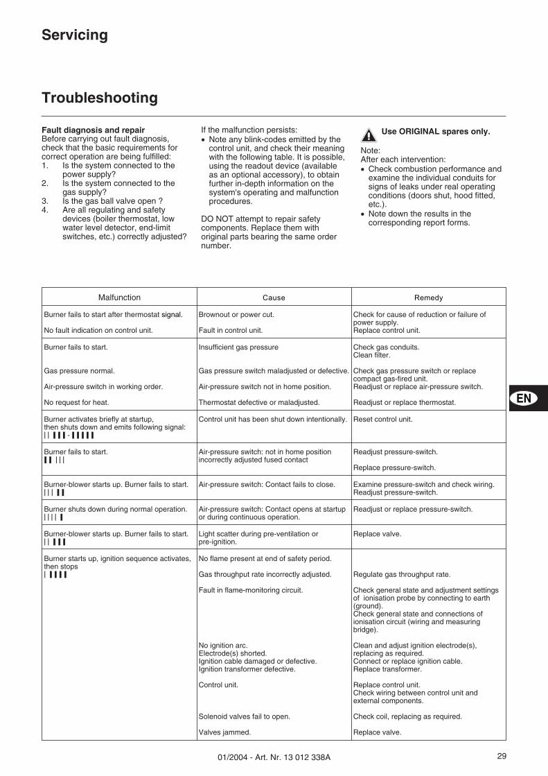
Malfunction Cause Remedy
Burner fails to start after thermostat signal.
No fault indication on control unit.
Brownout or power cut.
Fault in control unit.
Check for cause of reduction or failure ofpower supply.Replace control unit.
Burner fails to start.
Gas pressure normal.
Air-pressure switch in working order.
No request for heat.
Insufficient gas pressure
Gas pressure switch maladjusted or defective.
Air-pressure switch not in home position.
Thermostat defective or maladjusted.
Check gas conduits.Clean filter.
Check gas pressure switch or replacecompact gas-fired unit.Readjust or replace air-pressure switch.
Readjust or replace thermostat.
Burner activates briefly at startup,then shuts down and emits following signal:���������� - ������� �
Control unit has been shut down intentionally. Reset control unit.
Burner fails to start.��� �����
Air-pressure switch: not in home positionincorrectly adjusted fused contact
Readjust pressure-switch.
Replace pressure-switch.
Burner-blower starts up. Burner fails to start.��� ������
Air-pressure switch: Contact fails to close. Examine pressure-switch and check wiring.Readjust pressure-switch.
Burner shuts down during normal operation.����������
Air-pressure switch: Contact opens at startupor during continuous operation.
Readjust or replace pressure-switch.
Burner-blower starts up. Burner fails to start.������ ���
Light scatter during pre-ventilation orpre-ignition.
Replace valve.
Burner starts up, ignition sequence activates,then stops�������� �
No flame present at end of safety period.
Gas throughput rate incorrectly adjusted.
Fault in flame-monitoring circuit.
No ignition arc.Electrode(s) shorted.Ignition cable damaged or defective.Ignition transformer defective.
Control unit.
Solenoid valves fail to open.
Valves jammed.
Regulate gas throughput rate.
Check general state and adjustment settingsof ionisation probe by connecting to earth(ground).Check general state and connections ofionisation circuit (wiring and measuringbridge).
Clean and adjust ignition electrode(s),replacing as required.Connect or replace ignition cable.Replace transformer.
Replace control unit.Check wiring between control unit andexternal components.
Check coil, replacing as required.
Replace valve.

01/2004 - Art. Nr. 13 012 338A30
3101/2004 - Art. Nr. 13 012 338A
ErsatzteillisteSpare parts listPièces de rechangeWisselstukkenlijst
EK02B.12 GEK02B.18 G
32 11/2003 - Art. Nr. 13 012 338A
Po
s.D
ésig
nat
ion
Bez
eich
nu
ng
Om
sch
rijv
ing
Des
crip
tio
nA
rt. N
r.A
rt. N
r.E
KD
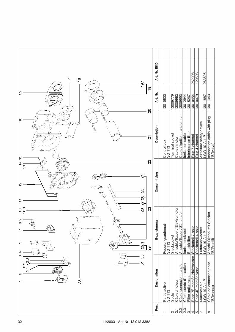
1P
artie
act
ive
SG
113
Feu
erun
gsau
tom
atS
G 1
13C
ontr
ol b
oxS
G 1
1313
0105
22
2S
ocle
Ste
ckso
ckel
Ter
min
al s
ocke
t13
0097
792.
1C
âble
/mot
eur
Ans
chlu
ßka
bel /
Ele
ktro
mot
orC
able
/ m
otor
1300
9982
2.2
Câb
le c
onne
xion
tran
sfo.
Ans
chlu
ßka
bel /
Zün
dtra
foC
able
/ ig
nitio
n tr
ansf
orm
er13
0099
932.
3C
âble
son
de d
’ioni
satio
nIo
nisa
tions
kabe
lIo
niza
tion
cabl
e13
0129
443
Filt
re a
ntip
aras
iteE
ntst
örfil
ter
Inte
rfer
ence
filte
r13
0152
674
Pris
e 7P
mon
tée
Noi
r/m
arro
nS
teck
erte
il 7-
polig
Plu
g 7-
chan
nel
1301
0454
2620
985
Pris
e 4P
mon
tée
vert
eS
teck
erte
il 4-
polig
Plu
g 4-
chan
nel
1301
0079
1205
987
Man
osta
t air
LGW
10-
A 1
PLu
ftdru
ckw
ächt
erLG
W 1
0-A
1 P
Air
failu
re s
afet
y de
vice
LGW
10-
A 1
P13
0118
8726
3625
8C
âble
de
conn
exio
n pr
ise
“B”(
vann
e)A
nsch
luß
kabe
l mit
Ste
cker
“B”(
Ven
til)
conn
ectio
n ca
ble
with
plu
g“B
”(va
lve)
1301
1343
3311/2003 - Art. Nr. 13 012 338A
Po
s.D
ésig
nat
ion
Bez
eich
nu
ng
Om
sch
rijv
ing
Des
crip
tio
nA
rt. N
r.A
rt. N
r.E
KD
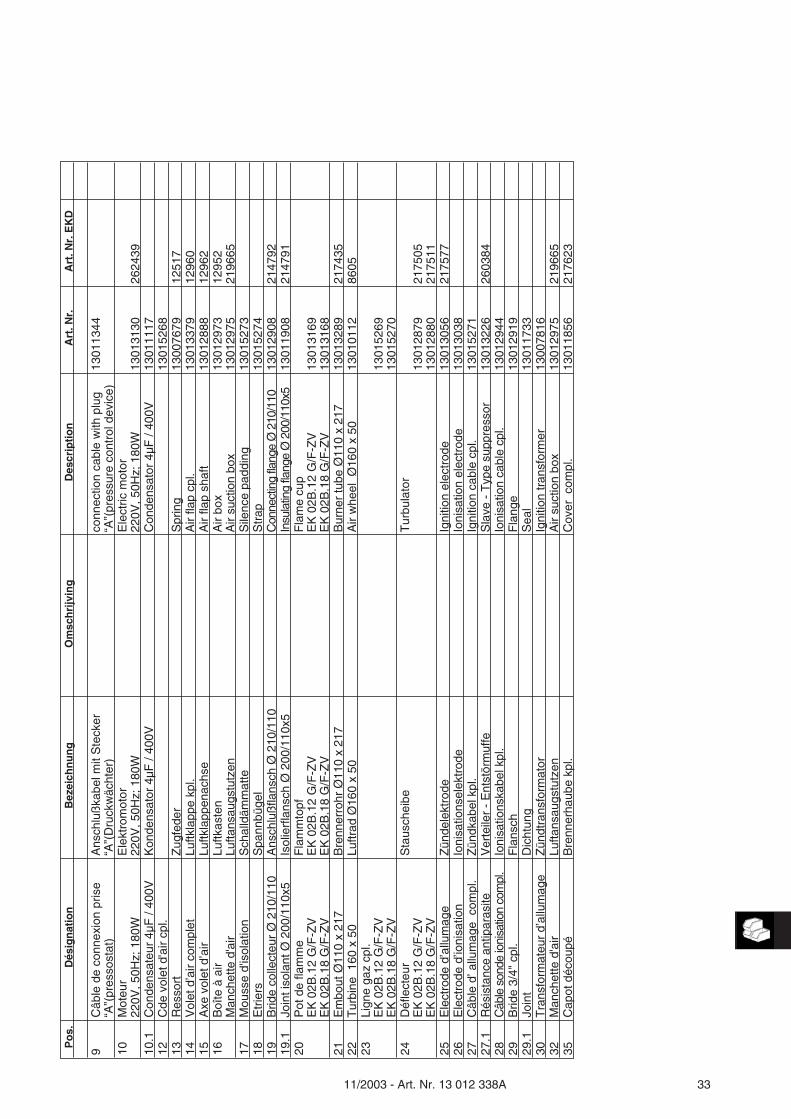
9C
âble
de
conn
exio
n pr
ise
“A”(
pres
sost
at)
Ans
chlu
ßka
bel m
it S
teck
er“A
”(D
ruck
wäc
hter
)co
nnec
tion
cabl
e w
ith p
lug
“A”(
pres
sure
con
trol
dev
ice)
1301
1344
10M
oteu
r22
0V, 5
0Hz;
180
WE
lekt
rom
otor
220V
, 50H
z; 1
80W
Ele
ctric
mot
or22
0V, 5
0Hz;
180
W13
0131
3026
2439
10.1
Con
dens
ateu
r 4µ
F /
400V
Kon
dens
ator
4µF
/ 40
0VC
onde
nsat
or 4
µF /
400V
1301
1117
12C
de v
olet
d'a
ir cp
l.13
0152
6813
Res
sort
Zug
fede
rS
prin
g13
0076
7912
517
14V
olet
d’a
ir co
mpl
etLu
ftkla
ppe
kpl.
Air
flap
cpl.
1301
3379
1296
015
Axe
vol
et d
’air
Luftk
lapp
enac
hse
Air
flap
shaf
t13
0128
8812
962
16B
oîte
à a
irM
anch
ette
d'a
irLu
ftkas
ten
Lufta
nsau
gstu
tzen
Air
box
Air
suct
ion
box
1301
2973
1301
2975
1295
221
9665
17M
ouss
e d'
isol
atio
nS
chal
ldäm
mat
teS
ilenc
e pa
ddin
g13
0152
7318
Etr
iers
Spa
nnbü
gel
Str
ap13
0152
7419
Brid
e co
llect
eur
Ø 2
10/1
10A
nsch
luß
flans
ch Ø
210
/110
Con
nect
ing
flang
eØ
210/
110
1301
2908
2147
9219
.1Jo
int i
sola
nt Ø
200
/110
x5Is
olie
rfla
nsch
Ø 2
00/1
10x5
Insu
latin
gfla
nge
Ø20
0/11
0x5
1301
1908
2147
9120
Pot
de
flam
me
EK
02B
.12
G/F
-ZV
EK
02B
.18
G/F
-ZV
Fla
mm
topf
EK
02B
.12
G/F
-ZV
EK
02B
.18
G/F
-ZV
Fla
me
cup
EK
02B
.12
G/F
-ZV
EK
02B
.18
G/F
-ZV
1301
3169
1301
3168
21E
mbo
ut Ø
110
x 21
7B
renn
erro
hr Ø
110
x 21
7B
urne
r tu
be Ø
110
x 21
713
0132
8921
7435
22T
urbi
ne 1
60 x
50
Luftr
ad Ø
160
x 50
Air
whe
el Ø
160
x 50
1301
0112
8605
23Li
gne
gaz
cpl.
EK
02B
.12
G/F
-ZV
EK
02B
.18
G/F
-ZV
1301
5269
1301
5270
24D
éfle
cteu
rE
K 0
2B.1
2 G
/F-Z
VE
K 0
2B.1
8 G
/F-Z
V
Sta
usch
eibe
Tur
bula
tor
1301
2879
1301
2880
2175
0521
7511
25E
lect
rode
d’a
llum
age
Zün
dele
ktro
deIg
nitio
n el
ectr
ode
1301
3056
2175
7726
Ele
ctro
de d
’ioni
satio
nIo
nisa
tions
elek
trod
eIo
nisa
tion
elec
trod
e13
0130
3827
Câb
le d
’ allu
mag
e c
ompl
.Z
ündk
abel
kpl
.Ig
nitio
n ca
ble
cpl.
1301
5271
27.1
Rés
ista
nce
antip
aras
iteV
erte
iler
- E
ntst
örm
uffe
Sla
ve -
Typ
e su
ppre
ssor
1301
3226
2603
8428
Câb
leso
nde
ioni
satio
nco
mpl
.Io
nisa
tions
kabe
l kpl
.Io
nisa
tion
cabl
e cp
l.13
0129
4429
Brid
e 3/
4" c
pl.
Fla
nsch
Fla
nge
1301
2919
29.1
Join
tD
icht
ung
Sea
l13
0117
3330
Tra
nsfo
rmat
eur
d’al
lum
age
Zün
dtra
nsfo
rmat
orIg
nitio
n tr
ansf
orm
er13
0078
1632
Man
chet
te d
'air
Lufta
nsau
gstu
tzen
Air
suct
ion
box
1301
2975
2196
6535
Cap
ot d
écou
péB
renn
erha
ube
kpl.
Cov
er c
ompl
.13
0118
5621
7623
34 11/2003 - Art. Nr. 13 012 338A
Po
s.D
ésig
nat
ion
Bez
eich
nu
ng
Om
sch
rijv
ing
Des
crip
tio
nA
rt. N
r.A
rt. N
r.E
KD
400
Gro
upe
vann
eG
asar
mat
urG
as tr
ain
401
Kit
join
tsO
'Rin
g S
etO
'Rin
g S
et40
2B
ride
MB
... 4
05/4
07F
lans
ch M
BF
lang
e M
B13
0129
1840
3V
anne
gaz
MB
DLE
407
B01
S20
Ven
tilV
alve
1301
2424
404
Pre
ssos
tat g
azD
ruck
wäc
hter
Pre
ss. c
ont.
devi
ce13
0100
7840
5V
anne
man
uelle
3/4
"K
ugel
hahn
Man
ual v
alve
1301
0970
406
Van
ne d
e sé
curit
é th
erm
ique
The
rmis
ch A
uslö
seve
ntil
The
rmal
ly tr
igge
red
safe
tyva
lve
1301
5272

3511/2003 - Art. Nr. 13 012 338A
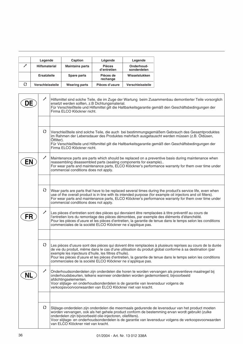
01/2004 - Art. Nr. 13 012 338A36
Legende Caption Légende Legende
� Hilfsmaterial Maintains parts Piècesd’entretien
Onderhoud-sonderdelen
Ersatzteile Spare parts Pièces derechange
Wisselstukken
� Verschleissteile Wearing parts Pièces d’usure Verschleissteile
DE� Hilfsmittel sind solche Teile, die im Zuge der Wartung beim Zusammenbau demontierter Teile vorsorglich
ersetzt werden sollten, z.B Dichtungsmaterial.Für Verschleißteile und Hilfsmittel gilt die Haltbarkeitsgarantie gemäß den Geschäftsbedingungen derFirma ELCO Klöckner nicht.
� Verschleißteile sind solche Teile, die auch bei bestimmungsgemäßem Gebrauch des Gesamtproduktesim Rahmen der Lebensdauer des Produktes mehrfach ausgetauscht werden müssen (z.B. Öldüsen,Ölfilter).Für Verschleißteile und Hilfsmittel gilt die Haltbarkeitsgarantie gemäß den Geschäftsbedingungen derFirma ELCO Klöckner nicht.
� Maintenance parts are parts which should be replaced on a preventive basis during maintenance whenreassembling disassembled parts (sealing components for example)..For wear parts and maintenance parts, ELCO Klöckner’s performance warranty for them over time undercommercial conditions does not apply.
� Wear parts are parts that have to be replaced several times during the product’s service life, even whenuse of the overall product is in line with its intended purpose (for example oil injectors and oil filters).For wear parts and maintenance parts, ELCO Klöckner’s performance warranty for them over time undercommercial conditions does not apply.
� Les pièces d’entretien sont des pièces qui devraient être remplacées à titre préventif au cours del’entretien lors du remontage des pièces démontées, par exemple des éléments d’étanchéité.Pour les pièces d’usure et les pièces d’entretien, la garantie de tenue dans le temps selon les conditionscommerciales de la société ELCO Klöckner ne s’applique pas.
� Les pièces d’usure sont des pièces qui doivent être remplacées à plusieurs reprises au cours de la duréede vie du produit, même dans le cas d’une utilisation du produit global conforme à sa destination (parexemple les injecteurs d’huile, les filtres d’huile).Pour les pièces d’usure et les pièces d’entretien, la garantie de tenue dans le temps selon les conditionscommerciales de la société ELCO Klöckner ne s’applique pas.
� Onderhoudsonderdelen zijn onderdelen die horen te worden vervangen als preventieve maatregel bijonderhoudsbeurten, telkens wanneer onderdelen worden gedemonteerd, bijvoorbeeldafdichtingselementen.Voor slijtage- en onderhoudsonderdelen is de garantie van levensduur volgens deverkoopsvoorvoorwaarden van ELCO Klöckner niet van kracht.
� Slijtage-onderdelen zijn onderdelen die meermaals gedurende de levensduur van het product moetenworden vervangen, ook als het gehele product conform de bestemming ervan wordt gebruikt (zulkeonderdelen zijn bijvoorbeeld olie-injectoren, oliefilters).Voor slijtage- en onderhoudsonderdelen is de garantie van levensduur volgens de verkoopsvoorwaardenvan ELCO Klöckner niet van kracht.
EN
FR
NL
3701/2004 - Art. Nr. 13 012 338A
Elektro- und HydraulikschemaElectric and hydraulic diagramsSchémas électrique et hydrauliqueElektrische en hydraulische schema
EK02B.12 GEK02B.18 G
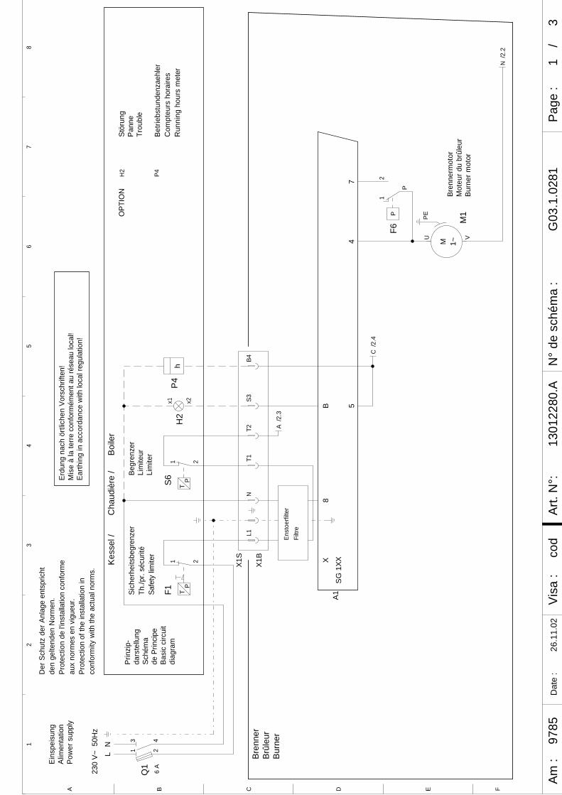
A B C FED
Am :
Visa
:Ar
t. N
°:N
° de
sch
éma
:/
Page
:D
ate
:1
1301
2280
.AG
03.1
.028
1co
d97
8526
.11.
023
12
34
56
78
1 2
3 46
A
Q1
1 2
TP
F1
NL1
12
P
PF6
PEU V
1~M
M1
T2S3x1 x2
H2
B4
hP4
T11 2
TPS6
/2.2
N
/2.4
C
/2.3
A
230
V~ 5
0Hz
NL
Eins
peis
ung
Alim
enta
tion
Pow
er s
uppl
y
Kes
sel /
Cha
udiè
re /
Boi
ler
Sich
erhe
itsbe
gren
zer
Th./p
r. sé
curit
éSa
fety
lim
iter
Begr
enze
rLi
mite
urLi
mite
r
Prin
zip-
dars
tellu
ngSc
hém
ade
Prin
cipe
Basi
c ci
rcui
tdi
agra
m
Der
Sch
utz
der A
nlag
e en
tspr
icht
den
gelte
nden
Nor
men
.Pr
otec
tion
de l'i
nsta
llatio
n co
nfor
me
aux
norm
es e
n vi
gueu
r.Pr
otec
tion
of th
e in
stal
latio
n in
conf
orm
ity w
ith th
e ac
tual
nor
ms.
Erdu
ng n
ach
örtli
chen
Vor
schr
iften
!M
ise
à la
terre
con
form
émen
t au
rése
au lo
cal!
Earth
ing
in a
ccor
danc
e w
ith lo
cal r
egul
atio
n!
Stör
ung
Pann
eTr
oubl
e
Betri
ebst
unde
nzae
hler
Com
pteu
rs h
orai
res
Run
ning
hou
rs m
eter
OPT
ION
H2
P4
Bren
ner
Brûl
eur
Burn
er
X1S
X1B
Filtr
eEn
stoe
rfilte
r
74
A1X
SG
1XX
8B 5
Bren
nerm
otor
Mot
eur d
u br
ûleu
rBu
rner
mot
or
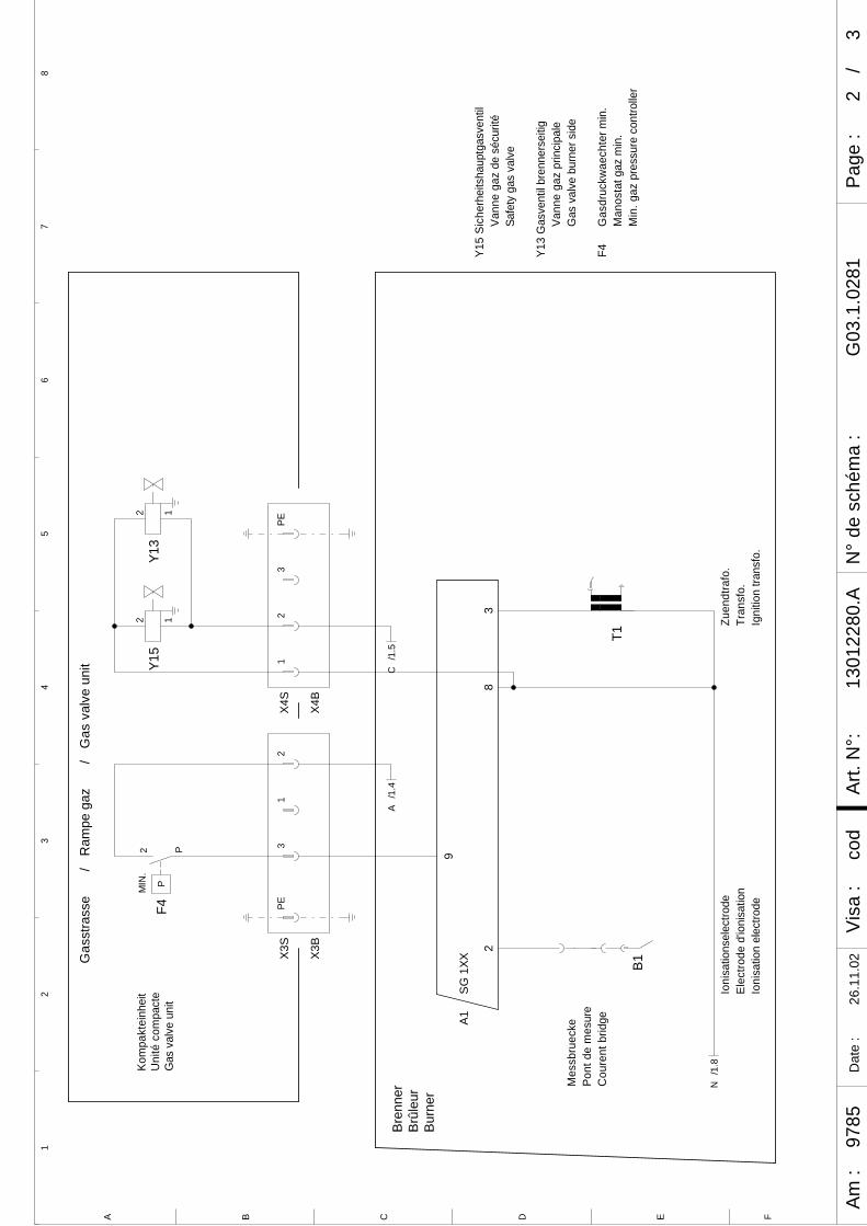
A B C FED
Am :
Visa
:Ar
t. N
°:N
° de
sch
éma
:/
Page
:D
ate
:2
1301
2280
.AG
03.1
.028
1co
d97
8526
.11.
023
12
34
56
78
21
23
PE
2 P
PF4
2 1Y1
5
1
2 1Y1
3
3PE
B1T1
/1.4
A
/1.8
N
/1.5
C
/G
as v
alve
uni
t
Kom
pakt
einh
eit
Uni
té c
ompa
cte
Gas
val
ve u
nit
X4B
X4S
X3B
X3S
/R
ampe
gaz
Gas
stra
sse
MIN
.
Zuen
dtra
fo.
Tran
sfo.
Igni
tion
trans
fo.
Bren
ner
Brûl
eur
Burn
er
Mes
sbru
ecke
Pont
de
mes
ure
Cou
rent
brid
ge
Ioni
satio
nsel
ectro
deEl
ectro
de d
'ioni
satio
nIo
nisa
tion
elec
trode
Y15
Sich
erhe
itsha
uptg
asve
ntil
Vann
e ga
z de
séc
urité
Safe
ty g
as v
alve
Y13
Gas
vent
il br
enne
rsei
tigVa
nne
gaz
prin
cipa
leG
as v
alve
bur
ner s
ide
9
82
3
A1S
G 1
XX
F4G
asdr
uckw
aech
ter m
in.
Man
osta
t gaz
min
.M
in. g
az p
ress
ure
cont
rolle
r
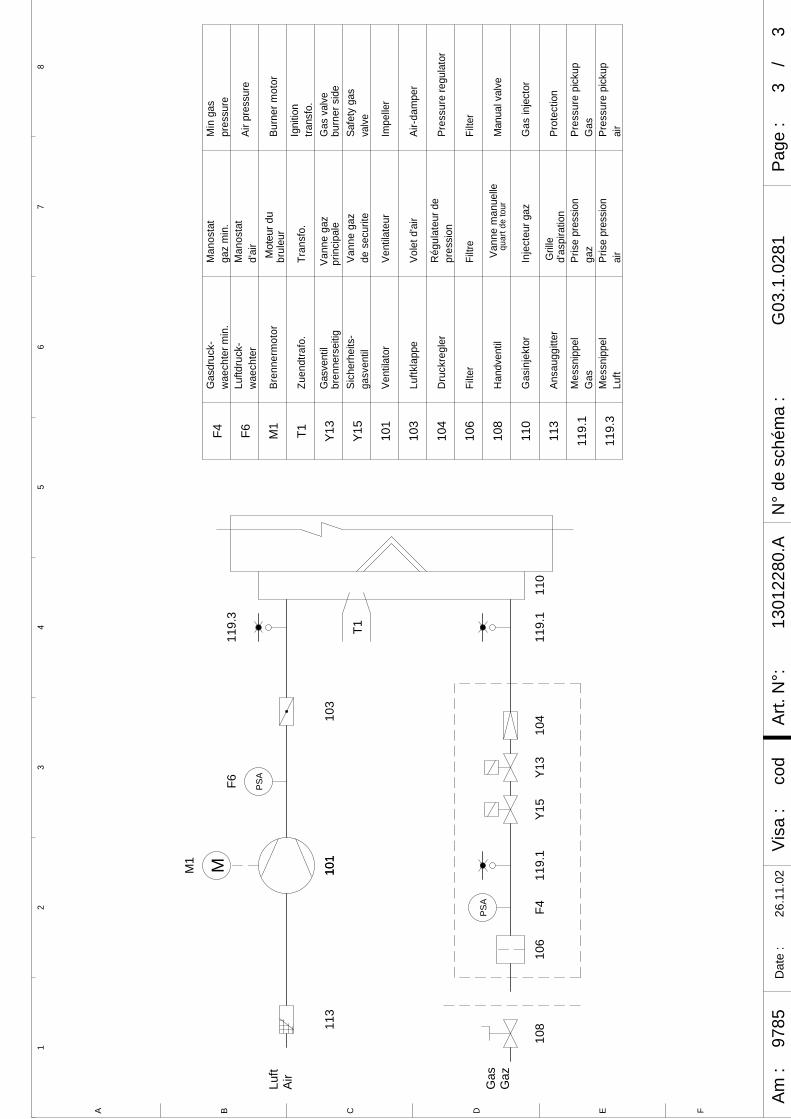
A B C FED
Am :
Visa
:Ar
t. N
°:N
° de
sch
éma
:/
Page
:D
ate
:3
1301
2280
.AG
03.1
.028
1co
d97
8526
.11.
023
12
34
56
78
PSA
M
PSA
Gas
Gaz
Luft
Air
M1
101
101
113
T1
110
Y15
F611
9.3
110
Gas
inje
ktor
Inje
cteu
r gaz
Gas
inje
ctor
113
Ansa
uggi
tter
Prot
ectio
nd'
aspi
ratio
nG
rille
119.
1M
essn
ippe
lPr
ise
pres
sion
Pres
sure
pic
kup
gaz
Gas
Gas
101
103
104
106
Vent
ilato
r
Luftk
lapp
e
Dru
ckre
gler
Filte
r
Vent
ilate
ur
Vole
t d'a
ir
Rég
ulat
eur d
epr
essi
on
Filtr
e
Impe
ller
Air-d
ampe
r
Filte
r
Pres
sure
regu
lato
r
Y15
Vann
e ga
zde
sec
urite
Safe
ty g
asva
lve
Sich
erhe
its-
gasv
entil
108
Han
dven
tilM
anua
l val
veVa
nne
man
uelle
quar
t de
tour
108
106
F411
9.1
119.
110
4Y1
3
Gas
vent
ilbr
enne
rsei
tigG
as v
alve
Vann
e ga
zpr
inci
pale
burn
er s
ide
Y13
103
T1Ig
nitio
ntra
nsfo
.
M1
brul
eur
Burn
er m
otor
Tran
sfo.
Zuen
dtra
fo.
Bren
nerm
otor
F6M
anos
tat
d'ai
rAi
r pre
ssur
eLu
ftdru
ck-
wae
chte
r
F4M
anos
tat
gaz
min
.M
in g
aspr
essu
reG
asdr
uck-
wae
chte
r min
.
Mot
eur d
u
119.
3M
essn
ippe
lPr
ise
pres
sion
Pres
sure
pic
kup
air
Luft
air

4101/2004 - Art. Nr. 13 012 338A

01/2004 - Art. Nr. 13 012 338A42

4301/2004 - Art. Nr. 13 012 338A
01/2004 - Art. Nr. 13 012 338A44
Fabriqué en EU. Made in EU. Hergestellt in EU.Docuent non contractuel. Non contractual document. Angaben ohne Gewähr.
ELCO KlöcknerA - 2544 Leobersdorf
ELCO - MAT N.V./S.A.ResearchparkPontbeeklaan 53B - 1731 Zellik
ELCO KlöcknerHeiztechnik GmbHD - 72379 Hechingen
ELCO b.v.Postbus 5057NL - 1410 AB Naarden