Embed Size (px)
Citation preview
EQCM contributions to the reactions of the nickel oxide electrode
T. and G. Schwitzgebel*Ohligschla� ger
des Saarlandes, Fachrichtung 8.13 Physikalische Chemie, Im Stadtwald,Universita� tD-66123 Germany. E-mail :Saarbru� cken, g.schwitzgebel=mx.uni-saarland.de ;Fax: ]49 681 302 4833; T el : ]49 681 302 2913
Received 21st June 2001, Accepted 10th September 2001First published as an Advance Article on the web 6th November 2001
Films of nickel hydroxide (thickness 0.35 lm) were electrochemically deposited on smooth and rough Auelectrodes of an electrochemical quartz crystal microbalance. The Ðlms consisted of a-Ni(OH) (di†ractogram)2and contained traces of and (IR). They were cycled (10 mV s~1) in KOH solutions (1, 0.1, 0.01NO3~ CO32~M) between 0 and 0.6 V as well as between [0.3 and 0.6 V vs. Hg/HgO iss. Cyclovoltammograms and massÑux curves were used to study the redox processes. As the mass Ñux peaks of the redox reactions of BodeÏsscheme and have di†erent signs and di†erent redox potentials they can easily(aIIH cIII@IV bIIH bIII) (E
a@c \ Eb@b),
be recognized. A new form of bIII (bIII*) was discovered, which forms on oxidation of aII, when not enoughKOH is present to be intercalated into cIII@IV, i.e. at low KOH concentrations and near the Au/Ðlm interfacewhereas near the Ðlm/solution interface aII transforms into bII (ageing). bIII* is supposed to contain O2~ defectsthat form from the foreign anion sites (substitutional defects) in aII. This explains its low oxidation potential
and its very slow reduction to bII. The reduction process was studied by mass controlled(Ea@b \ E
a@c)dissolution of the Ðlms in and by extending the lower vertex potential of the scan range from 0 to [0.3H2SO4V, so that reduction peaks of bIII* ([0.2 V) could be observed. This second reduction region, which lies about0.55 V below the main one, provides an explanation of the second discharge potential of Ni-accumulators.
IntroductionThe nickel oxide electrode (NOE) is used in various accumula-tor systems, e.g. Ni/Cd, Ni/Fe and Ni/metal hydride.1 Otherapplications are electrochrome devices in which the changebetween the colored oxidised state and the bleached reducedstate is exploited.2,3 The electrochemically active materials ofthe NOE are di†erent nickel hydroxides and oxyhydroxides,which as layered structures are able to intercalate water,cations and hydroxide ions from an alkaline electrolyte.1,4,5 Ina simpliÐed manner, their redox reactions are often represent-ed by BodeÏs reaction scheme:5
a-Ni(OH) (aII) often contains foreign anions from the deposi-2tion process6,7 and its oxidation to c-nickel-(III/IV)-oxyhydrox-ide (cIII@IV) is accompanied by a reversible intercalation of M`(M\ Li, Na, K) and OH~ between Some-Ni(OH)2-layers.what more detailed, this reaction (R1) can be written as
[(1] x)a-Ni(OH)2 É waH2O É (e
aNO3~, d
aCO32~)]
] y(K`] OH~)] (1] 2x)OH~
H [c-NiOOH É xNiO2 É wcH2O É (e
cNO3~, d
cCO32~)]
] (1] 2x ] wa[ w
c)H2O ] (1] 2x)e~ (R1)
where the proportions between the contents andH2O (wa
wc),
the degree of intercalation of KOH (y) and of oxidation(Ni3`/Ni4`) are left open and the anion impurities are thoseof the present study (see Experimental). Ageing of aII means astructural transformation into b-Ni(OH) (bII) and the expul-2sion of the impurities.6 Electrochemically active bII containsinterstitial water that leaves the structure on oxidationresulting in smaller lattice constants of bIII (R2) :
b-Ni(OH)2 É wbH2O ] OH~H b-NiOOH] (1 [ w
b)H2O ] e~
(R2)
In concentrated alkaline solution (c[ 4 M, 20 ¡C), the ageingof aII to bII occurs within a few hours so that only the redoxcouple bII/bIII is found in battery electrodes.6 In this solutionbII may be overoxidised to cIII@IV via bIII.1,4,5 The oxidationand reduction potentials for R1 are about 60È100 mV lowerthan for R2.5
By investigations with the electrochemical quartz crystalmicrobalance (EQCM) it has been shown that it is possible todistinguish between the two redox reactions :8h13 As a conse-quence of the intercalation and de-intercalation of K` andOH~, the oxidation of aII to cIII@IV leads to a mass increaseand the subsequent reduction to a mass decrease. In contrast,these mass changes are inverse for R2 because of the loss(oxidation) and uptake (reduction) of However, in mostH2O.of these papers the results have been obtained with thin Ðlms(usually about 100 nm) and the localization of the reactionshas not been discussed.
A special feature of the NOE, often observed in accumula-tors, is the second discharge potential, about 0.4È0.9 V lowerthan the main discharge potential.1 A possible explanation forthe occurrence of this phenomenon in bII/bIII battery materialshas been proposed by Delmas et al. who discussed the
5290 Phys. Chem. Chem. Phys., 2001, 3, 5290È5296 DOI: 10.1039/b105458a
This journal is The Owner Societies 2001(
Publ
ishe
d on
06
Nov
embe
r 20
01. D
ownl
oade
d by
Uni
vers
ity o
f W
inds
or o
n 28
/10/
2014
10:
04:5
6.
View Article Online / Journal Homepage / Table of Contents for this issue
reduction of an oxidised single nickel hydroxide grain which isonly locally in contact with the substrate.14,15 They concludedfrom galvanostatic discharge experiments and X-ray di†rac-tion (XRD) studies that the second discharge plateau is causedby the appearance of a b-nickel hydroxide phase that retainsNi3` ions and has a lower reduction potential than normalbII. It forms near the substrate at the end of the reduction. Asit is not ionically but electronically conductive, it causes aresidual positive charge in the active material by ionic iso-lation of oxyhydroxide.
The aim of the present work was to scrutinize the relationbetween mass changes and currents during the redox process
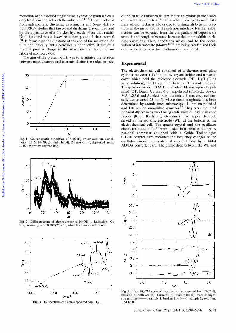
Fig. 1 Galvanostatic deposition of on smooth Au. Condi-Ni(OH)2tions : 0.1 M (unbu†ered) ; 2.5 mA cm~2 ; deposited mass :Ni(NO3)2D18 lg ; arrow: current stop.
Fig. 2 Di†ractogram of electrodeposited Radiation : CuNi(OH)2 .scanning rate : 0.005¡(2h) s~1 ; white line : smoothed values.Ka1 ;
Fig. 3 IR spectrum of electrodeposited Ni(OH)2 .
of the NOE. As modern battery materials exhibit particle sizesof several micrometers,16 the studies were performed withÐlms whose thickness allows one to distinguish between reac-tions at the metal and at the solution interface. Further infor-mation can be expected from the comparison of deposits onsmooth and rough substrates, because the latter exhibit thick-ness variations. Thus, conditions which lead to the obser-vation of intermediate b-forms14,15 are being created and theiroccurrence in cyclic redox reactions can be studied.
Experimental
The electrochemical cell consisted of a thermostated glasscylinder between a TeÑon quartz crystal holder and a plasticcover which held the reference electrode (RE: Hg/HgO insame solution), the Pt counter electrode (CE) and a stirrer.The quartz crystals [10 MHz, diameter : 14 mm, optically pol-ished (QT, Daun, Germany) or unpolished (Fil-Tech, BostonMA, USA)] had Au electrodes (diameter : 5 mm, electrochemi-cally active area : 23 mm2), whose mean roughness has beendetermined by atomic force microscopy : 11 nm on polishedand 140 nm on unpolished quartzes.17 They were mountedhorizontally between two O-ring seals made of instant siliconerubber (Roth, Karlsruhe, Germany). The upper electrodeserved as the working electrode (WE) at the bottom of theelectrochemical cell. The quartz crystal and the oscillatorcircuit (in-house built)18 were hosted in a metal container. Apersonal computer equipped with a Guide TechnologiesGT200 counter card recorded the frequency changes of theoscillator circuit and controlled a potentiostat by a 14-bitAD/DA converter card. The ohmic drop between the WE and
Fig. 4 First EQCM cycle of two identically prepared fresh Ni(OH)2Ðlms on smooth Au. (a) : Current ; (b) : mass Ñux ; (c) : mass changes ;straight line (ÈÈ): sample 1 ; broken line (È È È) : sample 2 ; solution :1 M KOH.
Phys. Chem. Chem. Phys., 2001, 3, 5290È5296 5291
Publ
ishe
d on
06
Nov
embe
r 20
01. D
ownl
oade
d by
Uni
vers
ity o
f W
inds
or o
n 28
/10/
2014
10:
04:5
6.
View Article Online
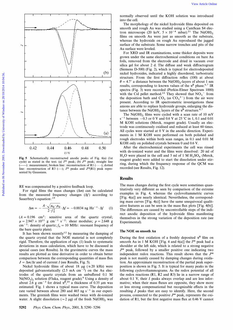
Fig. 5 Schematically reconstructed anodic peaks of Fig. 6(a) (1stcycle) as stated in the text. (a) Iox peak ; (b) Jox peak ; straight line(ÈÈ): measurement ; broken line : reconstruction of R1 (È È È) ; dottedline : reconstruction of R3 (- - -) ; Iox peaks and Jox(R1) peak repre-sented by Gaussians.
RE was compensated by a positive feedback loop.For rigid Ðlms the mass changes (*m) can be calculated
from the measured frequency changes (*f ) according toSauerbreyÏs equation :19
*m\ [A É JkQ É oQ
2 É f 02É*f\ [0.8834 ng Hz~1 É*f (1)
(A\ 0.196 cm2 : sensitive area of the quartz crystal ;k \ 2.947] 1011 g cm~1 s~2 : shear modulus ; o \ 2.648 gcm~3 : density of quartz ; MHz: resonant frequency off0\ 10the bare quartz plate).
It has been shown recently12 by measuring the damping ofthe quartz crystal that the NOE material is not completelyrigid. Therefore, the application of eqn. (1) leads to systematicdeviations in mass calculation, which have to be discussed inspecial cases (see Results). In the gravimetric curves the massresults are plotted as time derivative in order to obtain bettercomparison between the corresponding quantities of mass ÑuxJ \ *m/*t and of current I (see Results, Fig. 5).
Nickel hydroxide Ðlms of about 18 lg (B20 kHz) weredeposited galvanostatically (2.5 mA cm~2) on the Au elec-trodes of the quartz crystals from an unbu†ered 0.1 M
solution (Fluka, reagent grade).9 Using a density ofNi(NO3)2about 2.6 g cm~3 for dried aII,20 a thickness of 0.35 lm wasestimated. Fig. 1 shows a typical mass curve. The depositionrate varied between about 280 and 465 ng s~1 in our experi-ments. The greenish Ðlms were washed twice with de-ionizedwater. A slight dissolution (D2 lg) of the fresh wasNi(OH)2
normally observed until the KOH solution was introducedinto the cell.
The morphology of the nickel hydroxide Ðlms deposited onsmooth and rough Au was studied using a CamScan S4 elec-tron microscope (20 keV, 5 ] 10~4 mbar).21 The Ni(OH)2Ðlms on smooth Au were just as smooth as the substrate,whereas the hydroxide on rough Au reproduced the jaggedsurface of the substrate. Some narrow trenches and pits of theAu surface were leveled.
For XRD and IR examinations, some thicker deposits weregrown under the same electrochemical conditions on bare Aufoils, removed from the electrode and dried in vacuum oversilica gel for about 2 d. The di†use and weak di†ractogram(Siemens D-500) (Fig. 2), which is typical for electrodepositednickel hydroxides, indicated a highly disordered, turbostraticstructure. From the Ðrst di†raction reÑex (100) at abouth \ 4.7¡ a distance between the of about 1 nmNi(OH)2-layersresults, corresponding to known values of the aII phase.6,7 IRspectra (Fig. 3) were recorded (Perkin-Elmer Spectrum 1000)with the CsI pellet method.22 They showed that fromNO3~the deposition bath and (as from the air wereCO2 CO32~)present. According to IR spectrometric investigations theseanions are able to replace hydroxide groups, enlarging the dis-tance between the layers of the aII structure.6,7Ni(OH)2The Ðlms were cycled with a scan rate of 10 mVNi(OH)2s~1 between [0.3 or 0 V and 0.6 V at 25 ¡C in 1, 0.1 and 0.01M KOH solutions (Merck, reagent grade). Usually an elec-trode was continuously oxidised and reduced at least 60 times.All cycles were started at 0 V in the anodic direction. Experi-ments in 1 M KOH were performed on both polished andrough electrodes within both scan ranges, in 0.1 and 0.01 MKOH only on polished crystals between 0 and 0.6 V.
After the electrochemical experiments the cell was rinsedwith de-ionized water and the Ðlms were dissolved : 20 ml of
were placed in the cell and 5 ml of 1 M (Merck,H2O H2SO4reagent grade) were added to start the dissolution under stir-ring, during which the frequency response of the QCM wasrecorded (see Results, Fig. 12).
ResultsThe mass changes during the Ðrst cycle were sometimes quan-titatively very di†erent as seen by comparison of the extremeexamples in Fig. 4, whereas the cyclovoltammetric curves[Fig. 4(a)] are nearly identical. Nevertheless, the correspond-ing mass curves [Fig. 4(c)] have the same unequivocal qualit-ative features as can be seen in the mass Ñux plots [Fig. 4(b)].The di†erences are caused by uncontrollable steps of the indi-rect anodic deposition of the hydroxide Ðlms manifestingthemselves in the strong variation of the deposition rate (seeExperimental).
The NOE on smooth Au
During the Ðrst oxidation of a freshly deposited aII Ðlm onsmooth Au in 1 M KOH [Fig. 4 and 6(a)] the Iox peak had ashoulder at the left side, which is related to a strong negativeJox peak, followed by a smaller positive one indicating twoindependent redox reactions. This result shows that the Joxpeak is not mainly caused by damping changes during oxida-tion. An approximate reconstruction of the partial peak super-position is shown in Fig. 5. It is typical for many peaks in thefollowing cyclovoltammograms. As the redox potential of allthe redox reactions (R1, R2 and R3) lie in a narrow range ofabout 0.1 V, their I peaks always overlap and are less infor-mative ; when their mass Ñuxes are opposite, they show moreor less strong compensational but recognizable e†ects in theresulting J peaks that are easy to identify. Here, the secondprocess, connected to the positive Jox peak, represents the oxi-dation of R1, but the Ðrst negative mass Ñux at 0.46 V cannot
5292 Phys. Chem. Chem. Phys., 2001, 3, 5290È5296
Publ
ishe
d on
06
Nov
embe
r 20
01. D
ownl
oade
d by
Uni
vers
ity o
f W
inds
or o
n 28
/10/
2014
10:
04:5
6.
View Article Online
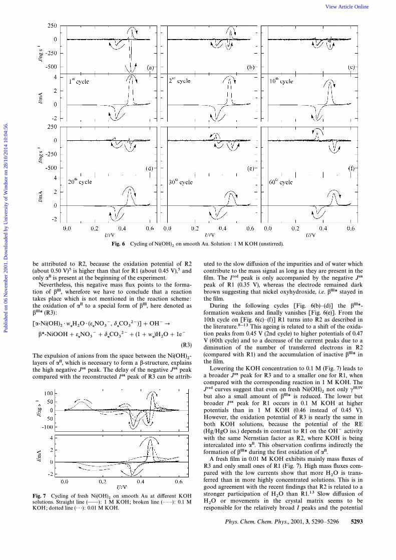
Fig. 6 Cycling of on smooth Au. Solution : 1 M KOH (unstirred).Ni(OH)2
be attributed to R2, because the oxidation potential of R2(about 0.50 V)5 is higher than that for R1 (about 0.45 V),5 andonly aII is present at the beginning of the experiment.
Nevertheless, this negative mass Ñux points to the forma-tion of bIII, wherefore we have to conclude that a reactiontakes place which is not mentioned in the reaction scheme:the oxidation of aII to a special form of bIII, here denoted asbIII* (R3) :
[a-Ni(OH)2 É waH2O É (e
aNO3~, d
aCO32~)]] OH~]
b*-NiOOH] eaNO3~] d
aCO32~] (1] w
a)H2O ] 1e~
(R3)
The expulsion of anions from the space between the Ni(OH)2-of aII, which is necessary to form a b-structure, explainslayersthe high negative Jox peak. The delay of the negative Jox peakcompared with the reconstructed Iox peak of R3 can be attrib-
Fig. 7 Cycling of fresh on smooth Au at di†erent KOHNi(OH)2solutions. Straight line (ÈÈ): 1 M KOH; broken line (È È È) : 0.1 MKOH; dotted line (É É É) : 0.01 M KOH.
uted to the slow di†usion of the impurities and of water whichcontribute to the mass signal as long as they are present in theÐlm. The Ired peak is only accompanied by the negative Joxpeak of R1 (0.35 V), whereas the electrode remained darkbrown suggesting that nickel oxyhydroxide, i.e. bIII* stayed inthe Ðlm.
During the following cycles [Fig. 6(b)È(d)] the bIII*-formation weakens and Ðnally vanishes [Fig. 6(e)]. From the10th cycle on [Fig. 6(c)È(f )] R1 turns into R2 as described inthe literature.8h13 This ageing is related to a shift of the oxida-tion peaks from 0.45 V (2nd cycle) to higher potentials of 0.47V (60th cycle) and to a decrease of the current peaks due to adiminution of the number of transferred electrons in R2(compared with R1) and the accumulation of inactive bIII* inthe Ðlm.
Lowering the KOH concentration to 0.1 M (Fig. 7) leads toa broader Jox peak for R3 and to a smaller one for R1, whencompared with the corresponding reaction in 1 M KOH. TheJred curves suggest that even on fresh not only cIII@IVNi(OH)2but also a small amount of bIII* is reduced. The lower butbroader Iox peak for R1 occurs in 0.1 M KOH at higherpotentials than in 1 M KOH (0.46 instead of 0.45 V).However, the oxidation potential of R3 is nearly the same inboth KOH solutions, because the potential of the RE(Hg/HgO iss.) depends in contrast to R1 on the OH~ activitywith the same Nernstian factor as R2, where KOH is beingintercalated into aII. This observation conÐrms indirectly theformation of bIII* during the Ðrst oxidation of aII.
A fresh Ðlm in 0.01 M KOH exhibits mainly mass Ñuxes ofR3 and only small ones of R1 (Fig. 7). High mass Ñuxes com-pared with the low currents show that more is trans-H2Oferred than in more highly concentrated solutions. This is ingood agreement with the recent Ðndings that R2 is related to astronger participation of than R1.13 Slow di†usion ofH2Oor movements in the crystal matrix seems to beH2Oresponsible for the relatively broad I peaks and the potential
Phys. Chem. Chem. Phys., 2001, 3, 5290È5296 5293
Publ
ishe
d on
06
Nov
embe
r 20
01. D
ownl
oade
d by
Uni
vers
ity o
f W
inds
or o
n 28
/10/
2014
10:
04:5
6.
View Article Online
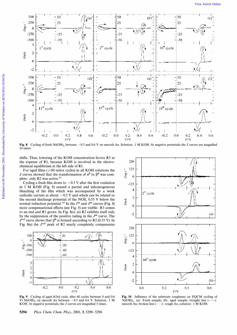
Fig. 8 Cycling of fresh between [0.3 and 0.6 V on smooth Au. Solution : 1 M KOH. At negative potentials the J curves are magniÐedNi(OH)210 times.
shifts. Thus, lowering of the KOH concentration favors R3 atthe expense of R1, because KOH is involved in the electro-chemical equilibrium at the left side of R1.
For aged Ðlms ([60 redox cycles) in all KOH solutions theJ curves showed that the transformation of aII to bII was com-plete : only R2 was active.21
Cycling a fresh Ðlm down to [0.3 V after the Ðrst oxidationin 1 M KOH (Fig. 8) caused a partial and inhomogeneousbleaching of the Ðlm which was accompanied by a weakcathodic current at about [0.2 V and which can be related tothe second discharge potential of the NOE, 0.55 V below thenormal reduction potential.14 In the Iox and Jox curves (Fig. 8)more compensational e†ects (see Fig. 5) are visible : R3 comesto an end and R1 grows. In Fig. 8(c)È(e) R2 exhibits itself onlyby the suppression of the positive tailing in the Jox curve. TheJred curve shows that bII is formed according to R2 (0.35 V). InFig. 8(e) the Jred peak of R2 nearly completely compensates
Fig. 9 Cycling of aged (63rd cycle, after 60 cycles between 0 and 0.6V) on smooth Au between [0.3 and 0.6 V. Solution : 1 MNi(OH)2KOH. At negative potentials, the J curves are magniÐed 5 times.
Fig. 10 InÑuence of the substrate roughness on EQCM cycling of(a) : Fresh sample ; (b) : aged sample ; straight line (ÈÈ):Ni(OH)2 .
smooth Au; broken line (È È È) : rough Au; solution : 1 M KOH.
5294 Phys. Chem. Chem. Phys., 2001, 3, 5290È5296
Publ
ishe
d on
06
Nov
embe
r 20
01. D
ownl
oade
d by
Uni
vers
ity o
f W
inds
or o
n 28
/10/
2014
10:
04:5
6.
View Article Online
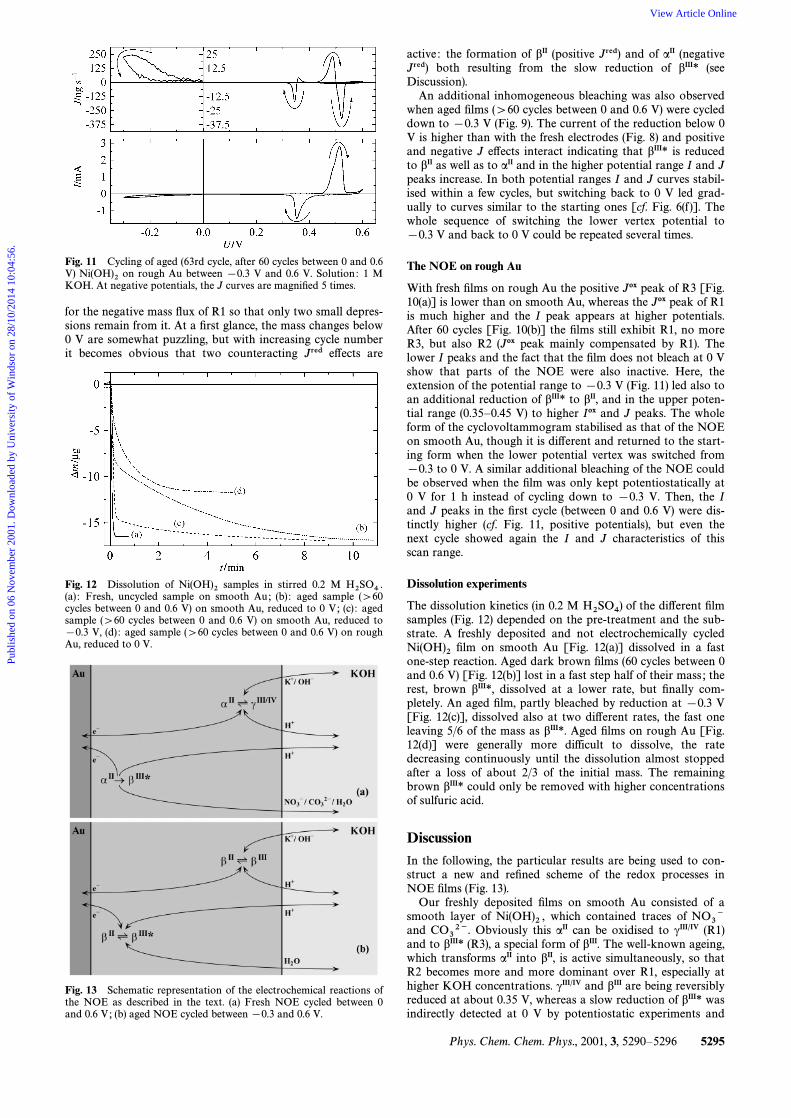
Fig. 11 Cycling of aged (63rd cycle, after 60 cycles between 0 and 0.6V) on rough Au between [0.3 V and 0.6 V. Solution : 1 MNi(OH)2KOH. At negative potentials, the J curves are magniÐed 5 times.
for the negative mass Ñux of R1 so that only two small depres-sions remain from it. At a Ðrst glance, the mass changes below0 V are somewhat puzzling, but with increasing cycle numberit becomes obvious that two counteracting Jred e†ects are
Fig. 12 Dissolution of samples in stirred 0.2 MNi(OH)2 H2SO4 .(a) : Fresh, uncycled sample on smooth Au; (b) : aged sample ([60cycles between 0 and 0.6 V) on smooth Au, reduced to 0 V; (c) : agedsample ([60 cycles between 0 and 0.6 V) on smooth Au, reduced to[0.3 V, (d) : aged sample ([60 cycles between 0 and 0.6 V) on roughAu, reduced to 0 V.
Fig. 13 Schematic representation of the electrochemical reactions ofthe NOE as described in the text. (a) Fresh NOE cycled between 0and 0.6 V; (b) aged NOE cycled between [0.3 and 0.6 V.
active : the formation of bII (positive Jred) and of aII (negativeJred) both resulting from the slow reduction of bIII* (seeDiscussion).
An additional inhomogeneous bleaching was also observedwhen aged Ðlms ([60 cycles between 0 and 0.6 V) were cycleddown to [0.3 V (Fig. 9). The current of the reduction below 0V is higher than with the fresh electrodes (Fig. 8) and positiveand negative J e†ects interact indicating that bIII* is reducedto bII as well as to aII and in the higher potential range I and Jpeaks increase. In both potential ranges I and J curves stabil-ised within a few cycles, but switching back to 0 V led grad-ually to curves similar to the starting ones [cf. Fig. 6(f )]. Thewhole sequence of switching the lower vertex potential to[0.3 V and back to 0 V could be repeated several times.
The NOE on rough Au
With fresh Ðlms on rough Au the positive Jox peak of R3 [Fig.10(a)] is lower than on smooth Au, whereas the Jox peak of R1is much higher and the I peak appears at higher potentials.After 60 cycles [Fig. 10(b)] the Ðlms still exhibit R1, no moreR3, but also R2 (Jox peak mainly compensated by R1). Thelower I peaks and the fact that the Ðlm does not bleach at 0 Vshow that parts of the NOE were also inactive. Here, theextension of the potential range to [0.3 V (Fig. 11) led also toan additional reduction of bIII* to bII, and in the upper poten-tial range (0.35È0.45 V) to higher Iox and J peaks. The wholeform of the cyclovoltammogram stabilised as that of the NOEon smooth Au, though it is di†erent and returned to the start-ing form when the lower potential vertex was switched from[0.3 to 0 V. A similar additional bleaching of the NOE couldbe observed when the Ðlm was only kept potentiostatically at0 V for 1 h instead of cycling down to [0.3 V. Then, the Iand J peaks in the Ðrst cycle (between 0 and 0.6 V) were dis-tinctly higher (cf. Fig. 11, positive potentials), but even thenext cycle showed again the I and J characteristics of thisscan range.
Dissolution experiments
The dissolution kinetics (in 0.2 M of the di†erent ÐlmH2SO4)samples (Fig. 12) depended on the pre-treatment and the sub-strate. A freshly deposited and not electrochemically cycled
Ðlm on smooth Au [Fig. 12(a)] dissolved in a fastNi(OH)2one-step reaction. Aged dark brown Ðlms (60 cycles between 0and 0.6 V) [Fig. 12(b)] lost in a fast step half of their mass ; therest, brown bIII*, dissolved at a lower rate, but Ðnally com-pletely. An aged Ðlm, partly bleached by reduction at [0.3 V[Fig. 12(c)], dissolved also at two di†erent rates, the fast oneleaving 5/6 of the mass as bIII*. Aged Ðlms on rough Au [Fig.12(d)] were generally more difficult to dissolve, the ratedecreasing continuously until the dissolution almost stoppedafter a loss of about 2/3 of the initial mass. The remainingbrown bIII* could only be removed with higher concentrationsof sulfuric acid.
DiscussionIn the following, the particular results are being used to con-struct a new and reÐned scheme of the redox processes inNOE Ðlms (Fig. 13).
Our freshly deposited Ðlms on smooth Au consisted of asmooth layer of which contained traces ofNi(OH)2 , NO3~and Obviously this aII can be oxidised to cIII@IV (R1)CO32~.and to bIII* (R3), a special form of bIII. The well-known ageing,which transforms aII into bII, is active simultaneously, so thatR2 becomes more and more dominant over R1, especially athigher KOH concentrations. cIII@IV and bIII are being reversiblyreduced at about 0.35 V, whereas a slow reduction of bIII* wasindirectly detected at 0 V by potentiostatic experiments and
Phys. Chem. Chem. Phys., 2001, 3, 5290È5296 5295
Publ
ishe
d on
06
Nov
embe
r 20
01. D
ownl
oade
d by
Uni
vers
ity o
f W
inds
or o
n 28
/10/
2014
10:
04:5
6.
View Article Online
directly by I and J e†ects of the cyclovoltammograms (10 mVs~1) below 0 V (Fig. 8, 9 and 11).
The oxidation of the Ðlm starts near the inter-Au/Ni(OH)2face,23 where R1 is impeded by a shortage of KOH whosedi†usion from the solution does not reach the deepest regionof the Ðlm, so that the oxidation proceeds in another direction(R3), where no intercalation is necessary and where the expul-sion of and foreign anions even pre-H2O (NO3~, CO32~)vents the approach of KOH. The anionic defects at OH~ siteswhich are occupying partially the gap between the Ni(OH)2-leave aII, thus allowing the formation of bIII* which is,layersas a b-structure, characterised by a lack of the gap. It can beassumed that the expulsion of these anions causes other zero-and one-dimensional defects which are similar to the O2~-defects found in pure well-crystallised bII.24 The reduction ofthese O2~-defects near empty OH~-positions in bIII* proceedsslowly because, as has been pointed out recently,14,15 the re-intercalation and di†usion of H` into such a defectivematerial is more difficult than into the less disturbed struc-tures at the Ðlm/solution interface. Therefore, bIII*, which hasformed once and is reduced rapidly only below 0 V, has alower reduction potential and remains during cycling between0 and 0.6 V at the bottom of the Ðlms. There, it serves only asan electrical connection for the upper part of the Ðlm at thesolution interface, where the normal ageing is observed.
This model implies that bIII* forms only in sufficiently thickaII Ðlms. A series of experiments in the literature8 supportsthis dependence on thickness : Only in the thickest aII sampleshave mass changes similar to those in our study beenobserved (but not commented on).
bIII* is reduced below 0 V mainly to bII conserving thedefects. However, the formation of aII in the low potentialregion (\0 V; Fig. 9) seems to disprove the given interpreta-tion, but it is very probable that small amounts of cIII@IV, whichhad formed at the beginning of the oxidation, were completelycovered by bIII*, so that their reduction is only possible afterthe reduction of bIII*.
This picture of the redox processes is in good agreementwith earlier microscopic observations of a reaction front start-ing at the substrate and traveling through the Ðlm toNi(OH)2the solution interface,23 and it is conÐrmed by the results ofthe dissolution experiments, aII and bII being rapidly and bIII*slowly dissolved. The mass of the dissolved parts of the Ðlmdepends on the degree of reduction in the low potential range[Fig. 12(b) and (c)] and on the roughness of the substrate[Fig. 12(d)], which clearly shows that bIII* accumulates at thedeepest places, in hollows and trenches of the Au surface. Inthe regions of reduced Ðlm thickness stable cycling of R1occurs.
ConclusionThe investigations presented here have shown that at places oflow KOH concentration a-Ni(OH) is oxidised to bIII*, a2special form of b-NiOOH. All experimental results led to theconclusion that bIII* contains defects which are reduced
mainly at about 0.55 V below the reduction of normal b-NiOOH. This observation provides an explanation of thesecond discharge potential of Ni accumulators. Beyond that,the role of anion impurities in the formation of defects and theanalysis of the mass Ñux peaks could be helpful in batteryapplications of the NOE.
AcknowledgementsFinancial support of the Fonds der Chemischen Industrie isgratefully acknowledged.
References1 J. McBreen, in Modern Aspects of Electrochemistry, V ol. 21, ed. J.
OÏM. Bockris, R. E. White and B. E. Conway, Plenum Press,New York and London, 1990, pp. 29È63.
2 C. Avino, S. Panero and B. Scrosati, J. Mater. Chem., 1993, 3,1259.
3 S. Passerini, B. Scrosati, V. Hermann, C. Holmblad and T. Bart-lett, J. Electrochem. Soc., 1994, 141, 1025.
4 P. Oliva, J. Leonardi, J. F. Laurent, C. Delmas, J. J. Braconnier,M. Figlarz, F. Fievet and A. de Guibert, J. Power Sources, 1982,8, 229.
5 H. Bode, K. Dehmelt and J. Witte, Z. Anorg. Allg. Chem., 1969,366, 1.
6 A. Delahaye-Vidal, B. Beaudoin, N. K. Tekaia-Sac-Epe� e,Elhissen, A. Audemer and M. Figlarz, Solid State Ion., 1996, 84,239.
7 P. Genin, A. Delahaye-Vidal, F. Portemer, K. Tekaia-Elhissenand M. Figlarz, Eur. J. Solid State Inorg. Chem., 1991, 28, 505.
8 Y. Mo, E. Hwang and D. A. Scherson, J. Electrochem. Soc., 1995,143, 37.
9 M.-S. Kim, T.-S. Hwang and K.-B. Kim, J. Electrochem. Soc.,1997, 144, 1537.
10 M.-S. Kim and K.-B. Kim, J. Electrochem. Soc., 1998, 145, 507.11 H. Gonsalves and A. R. Hillman, J. Electroanal. Chem., 1998, 454,
183.12 R. A. Etchenique and E. J. Calvo, J. Electrochem. Soc., 2001, 148,
A361.13 H. M. French, M. J. Henderson, A. R. Hillman and E. Vieil, J.
Electroanal. Chem., 2001, 500, 192.14 C. C. Tessier, M. C. Denage and C. Delmas, J.Le� ger, Me� ne� trier,
Electrochem. Soc., 1999, 146, 924.15 C. Delmas, C. Tessier, C. and M. Proc. Electro-Le� ger Me� ne� trier,
chem. Soc., 1999, 98-15, 11.16 S. Deabate, F. Fourgeot and F. Henn, Ionics, 1999, 5, 371.17 A. Bund, H. Chmiel and G. Schwitzgebel, Phys. Chem. Chem.
Phys., 1999, 1, 3933.18 C. Dusemund and G. Schwitzgebel, Ber. Bunsenges. Phys. Chem.,
1991, 95, 1543.19 G. Sauerbrey, Z. Phys., 1959, 155, 206.20 H. Bode, K. Dehmelt and J. Witte, Electrochim. Acta, 1966, 11,
1079.21 T. Thesis, Saarland University, 2001.Ohligschla� ger, Saarbru� cken,22 F. Portemer, A. Delahaye-Vidal and M. Figlarz, J. Electrochem.
Soc., 1992, 139, 671.23 G. W. D. Briggs and M. Fleischmann, T rans. Faraday Soc., 1971,
67, 2397.24 C. Greaves and M. A. Thomas, Acta Crystallogr., Sect. B, 1986,
42, 51.
5296 Phys. Chem. Chem. Phys., 2001, 3, 5290È5296
Publ
ishe
d on
06
Nov
embe
r 20
01. D
ownl
oade
d by
Uni
vers
ity o
f W
inds
or o
n 28
/10/
2014
10:
04:5
6.
View Article Online


![[2 + 3] Cycloaddition Reactions of Azido Metal Complexes ...zfn.mpdl.mpg.de/data/Reihe_B/27/ZNB-1972-27b-0745.pdf · CYCLOADDITION REACTIONS OF AZIDO METAL COMPLEXES 747 tures (TCH,](https://img.pdfslide.org/doc/110x75/60648a2df6edbd732a617206/2-3-cycloaddition-reactions-of-azido-metal-complexes-zfnmpdlmpgdedatareiheb27znb-1972-27b-0745pdf.jpg)