Embed Size (px)
Citation preview

Forschungszentrum Karlsruhe in der Helmholtz-Gemeinschaft Wissenschaftliche Berichte FZKA 6983 Contributions to the Design of the Electron Cyclotron Launching Upper Port Plug System (ECLUPPS) Intermediate Report May 2003 – Oct. 2003 V. Heinzel, E. Stratmanns, K. Kleefeldt, R. Heidinger Institut für Reaktorsicherheit Institut für Materialforschung November 2004


Forschungszentrum Karlsruhe
in der Helmholtz-Gemeinschaft
Wissenschaftliche Berichte
Forschungszentrum Karlsruhe GmbH, Karlsruhe
2004
FZKA 6983
Contributions to the Design of
the Electron Cyclotron Launching
Upper Port Plug System (ECLUPPS)
Intermediate Report May 2003 – Oct. 2003
V. Heinzel, E. Stratmanns, K. Kleefeldt*, R. Heidinger
Institut für Reaktorsicherheit Institut für Materialforschung
*Ingenieurbüro K. Kleefeldt

Intermediate Report Prepared by Ingenieurbüro K. W. Kleefeldt, Pfinzstraße 46, 76689 Karlsdorf-Neuthard In Collaboration with Forschungszentrum Karlsruhe GmbH under Contract 425/20247646/IRS
Impressum der Print-Ausgabe:
Als Manuskript gedruckt Für diesen Bericht behalten wir uns alle Rechte vor
Forschungszentrum Karlsruhe GmbH
Postfach 3640, 76021 Karlsruhe
Mitglied der Hermann von Helmholtz-Gemeinschaft Deutscher Forschungszentren (HGF)
ISSN 0947-8620
urn:nbn:de:0005-069837
i
Beitrag zur Entwicklung des Electron-Cyclotron-Heizsystems in der oberen Port-Ebene von ITER
Zusammenfassung
Für den internationalen Fusionsreaktor ITER (International Thermonuclear Experimental Reactor) wird derzeit ein Heizsystem zur Plasmastabilisierung mit Hilfe von Mikrowellen entwickelt, das sogenannte “Electron Cyclotron Heating and Current Drive” (EC H&CD) System. Die Mikrowellen werden über dafür vorgesehen Öffnungen (ports) im Vacuumbehälter in zwei verschiedenen Ebenen eingekoppelt. Das Forschungszentrum Karlsruhe bearbeitet federführend das System für die obere Port-Ebene von ITER. Innerhalb des FZK ist das IRS zuständig für die Auslegung der mechanischen Struktur dieser Heizeinsätze, der sogenannten “Upper Port Plugs” (UPP). Neben der gekühlten Tragestruktur von etwa 5 m Länge gehört dazu auch das dem Plasma und der Neutronenstrahlung ausgesetzte Abschirmelement in der ersten Wand. Andere Einbauten werden von externen Partnern entwickelt. Aufgabe des Vertrages zwischen FZK und dem Beratungsingenieur ist die Unterstützung und Ergänzung der Entwicklungsarbeiten des FZK/IRS bei der Konzeptfindung und mechanischen Auslegung des UPP. Der entsprechende Beitrag des Auftragnehmers in der Zeit von Mai 2003 bis Oktober 2003 wird in diesem Bericht dargestellt. Er konzentriert sich auf Entwürfe für kritische Komponenten und auf Abschätzungen zu deren mechanischen und thermo-hydraulischen Verhalten. Die Arbeit wurde in enger Zusammenarbeit mit dem IRS und dem IMF-I durchgeführt.

ii
Abstract
For the International Thermonuclear Experimental Reactor (ITER) a port plug system is under development, comprising sets of equatorial and inclined devices for testing, diagnostics and heating purposes. Forschungszentrum Karlsruhe (FZK) is responsible for the Electron Cyc lotron Heating and Current Drive (EC H&CD) system installed in the upper ports of ITER. Within FZK, IRS contributes to developing the mechanical structure of the upper port plug (UPP), including the blanket shield module. Other internals are designed by external groups. The aim of the present contract between FZK and the consulting engineer is to stipulate and support the work to be performed at FZK/IRS in the field of mechanical design of the UPP in the early phase. The contractor’s contribution during the period May 2003 to October 2003 is described in this report. It focuses on the conceptual design of the UPP components and on estimates related to mechanical and thermal-hydraulics issues. This work has been performed together with IRS and in close collaboration with IMF-I.

ECLUPPS Design Activities, Intermediate Report May 2003 – Oct. 2003 III
Table of Contents
1 INTRODUCTION .........................................................................................................................1
2 WORK ACHIEVED DURING THE REPORTING PERIOD .................................................3 2.1 BACKGROUND AND CONCEPTUAL DESIGN OF THE UPPER PORT PLUG ....................................3
2.1.1 Current beam line reference model .................................................................................3 2.1.2 Adaptation of the launcher structure ...............................................................................4 2.1.3 Concept of blanket shield module attachment .................................................................4
2.1.3.1 Estimate of tensile stresses in the bolts .......................................................................4 2.1.4 Outline of launcher assembly/disassembly ......................................................................5 2.1.5 Blanket shield module design ..........................................................................................6
2.1.5.1 The outer structure of the blanket shield module ........................................................6 2.1.5.2 Sets of mirrors and mirror holders ..............................................................................8 2.1.5.3 Filler blocks for maximum shielding effectiveness .....................................................8 2.1.5.4 Schematic of the front shield blocks............................................................................8
2.2 ESTIMATES RELATED TO MECHANICAL AND THERMAL-HYDRAULIC ISSUES............................9 2.2.1 Expected distortions of launcher structure caused by heavy disruptions .......................9 2.2.2 Temperature difference in a slab with internal heat load .............................................10
2.2.2.1 Model and assumptions .............................................................................................10 2.2.2.2 Evaluation ..................................................................................................................10 2.2.2.3 Conclusion to section 2.2.2........................................................................................11
2.2.3 Thermal-hydraulics performance of front panel ..........................................................12 2.2.3.1 Objectives and general configuration ........................................................................12 2.2.3.2 The thermal-hydraulic program HYDRO..................................................................12 2.2.3.3 Evaluation ..................................................................................................................14 2.2.3.4 Summary of front panel thermal-hydraulics ..............................................................14
2.2.4 Thermal-hydraulics performance of double-wall BSM shell ........................................15 2.2.4.1 Objectives and general configuration ........................................................................15 2.2.4.2 Geometrical model.....................................................................................................15 2.2.4.3 Computational model.................................................................................................16 2.2.4.4 Evaluation and results ................................................................................................17 2.2.4.5 Summary of BSM shell thermal-hydraulics ..............................................................18
2.2.5 Thermal-hydraulics performance of front mirrors ........................................................19 2.2.5.1 Objectives and configuration .....................................................................................19 2.2.5.2 Geometrical model.....................................................................................................19 2.2.5.3 Evaluation and result .................................................................................................20 2.2.5.4 Conclusion to preliminary front mirror thermal-hydraulics ......................................21
2.3 OUTLINE OF MODELS NEEDED FOR DETAILED ANALYSES ......................................................21 2.3.1 Models for neutronics analysis ......................................................................................21 2.3.2 Models for mechanical analysis ....................................................................................21 2.3.3 Models for thermal-hydraulics analysis ........................................................................22
2.4 COLLABORATION WITH OTHER GROUPS INVOLVED IN THE PROJECT .....................................22 2.5 DOCUMENTS PREPARED DURING THE REPORTING PERIOD.....................................................22
2.5.1 Publications ...................................................................................................................22 2.5.2 Reports ...........................................................................................................................23 2.5.3 Workshops......................................................................................................................23 2.5.4 Minutes and notes ..........................................................................................................23
3 NEXT STEPS ...............................................................................................................................23
4 SUMMARY AND CONCLUSIONS ..........................................................................................25

IV
REFERENCES.....................................................................................................................................27
FIGURES..............................................................................................................................................28

ECLUPPS Design Activities, Intermediate Report May 2003 – Oct. 2003 V
List of Tables TABLE 1: DIMENSIONS AND MOMENTS OF INERTIA OF LAUNCHER CROSS SECTIONS ..............................9 TABLE 2: ASSUMED WORST CASE ELECTROMAGNETIC LOADS AT THE FREE END OF LAUNCHER ...........9 TABLE 3: RESULTS OF FRONT PANEL THERMAL-HYDRAULICS ASSESSMENT .........................................14 TABLE 4: MAIN RESULTS OF BSM SHELL THERMAL-HYDRAULICS........................................................18 TABLE 5: MAIN RESULTS OF FRONT MIRROR THERMAL-HYDRAULICS...................................................21
List of Diagrams DIAGRAM 1: SLAB MODEL WITH INTERNAL HEAT..................................................................................10 DIAGRAM 2: TEMPERATURE DIFFERENCE IN A SS316 SLAB WITH INTERNAL HEAT AT DEPTH FROM FW
.......................................................................................................................................................11 DIAGRAM 3: EXPECTED NUCLEAR HEATING RATE VS. DEPTH IN THE UPP............................................11 DIAGRAM 4: BOCK DIAGRAM OF FRONT PANEL FLOW CHANNELS.........................................................12 DIAGRAM 5: SCHEMATIC OF THE BSM SHELL AND FRONT PANEL.........................................................15 DIAGRAM 6: COOLING CHANNEL AND HEAT STRUCTURE COMPONENT DEFINITION..............................16 DIAGRAM 7: PROJECTION OF COOLING GAP ONTO FLANGE/SHELL WELDING PLANE .............................17 DIAGRAM 8: EXAMPLE OF FLOW VELOCITY VARIATION IN BSM SHELL COOLING CHANNELS ..............18 DIAGRAM 9: FRONT MIRROR CHANNEL AND HEAT STRUCTURE MODEL ................................................20
List of Figures FIGURE 1: MAIN COMPONENTS OF UPP WITH REFERENCE BEAM LINE ARRANGEMENT ........................27 FIGURE 2: LAUNCHER CROSS SECTIONS AT 1M, 2.8M AND 4.5M FROM MAIN FLANGE (FROM LEFT
TORIGHT) ........................................................................................................................................27 FIGURE 3: REVISED LAUNCHER CROSS SECTIONS AT AXIAL POSITIONS DEFINED IN FIGURE 4..............27 FIGURE 4: OLD (TOP) AND REVISED (BOTTOM) LAUNCHER DESIGN.......................................................27 FIGURE 5: BLANKET SHIELD MODULE ATTACHMENT.............................................................................27 FIGURE 6: FRONT SHIELD ASSEMBLY/DISASSEMBLY SCHEME ...............................................................27 FIGURE 7: LAUNCHER ASSEMBLY/DISASSEMBLY SCHEME ....................................................................27 FIGURE 8: BLANKET SHIELD MODULE INTERNALS .................................................................................27 FIGURE 9: CONCEPTUAL DESIGN OF BLANKET SHIELD MODULE HOUSING ............................................27 FIGURE 10: CONCEPTUAL DESIGN OF FRONT PANEL ..............................................................................27 FIGURE 11: CUT-OUT IN THE FRONT PANEL AS PRODUCED BY RF BEAMS .............................................27 FIGURE 12: REFERENCE BEAM CONFIGURATION INTERFERES WITH COOLING CHANNELS.....................27 FIGURE 13: CATIA MODEL VS. ENGINEERED RF BEAM CUT-OUT IN FRONT PANEL ..............................27 FIGURE 14: FRONT PANEL HEADER DESIGN ...........................................................................................27 FIGURE 15: BSM STRUCTURE COOLING CONCEPT .................................................................................27 FIGURE 16: SCHEMATIC OF SETS OF MIRRORS ATTACHED TO MIRROR HOLDERS ..................................27 FIGURE 17: MIRROR ATTACHMENT AND COOLING CONCEPT .................................................................27 FIGURE 18: FIRST DRAFT OF FRONT MIRROR CONCEPT ..........................................................................27 FIGURE 19: FRONT MIRROR COLLISION WITH BSM SIDE WALL .............................................................27 FIGURE 20: FRONT SHIELD BLOCK CONCEPTUAL DESIGN ......................................................................27

ECLUPPS Design Activities, Intermediate Report May 2003 – Oct. 2003 1
1 Introduction A port plug system is under development, comprising sets of equatorial and inclined devices that penetrate the safety barriers of the ITER machine, i.e., the vacuum vessel, cryostat and biological shield. The port plugs contain testing, diagnostics and heating systems. FZK is responsible for the Electron Cyclotron Heating and Current Drive (EC H&CD) system installed in 3 (or 4) out of 18 upper ports of ITER, in collaboration with external groups. Within FZK, IMF I is the project engineer. IRS contributes to developing the mechanical structure of the upper port plug (UPP). This includes the port plug main structure, vacuum vessel flange, blanket shield module and neutron ics analysis.
According to the project time schedule, a conceptual design of the UPP shall be completed by September 2004 with details on design, thermo-mechanics, hydraulics and neutronics due in April 2004. The mechanical design proceeds with the following steps in collaboration with FOM Instituut voor Plasmafysica Rijnhuizen and CRPP, Lausanne: Preparation of CATIA models of the launcher main structure, design of blanket shield module structure including cooling scheme, investigation of electromagnetic loads, developing the cooling scheme of the launcher structure, and providing CAD models for neutronics analysis.
The present half-year contract is the second in a row, aiming at supporting the work performed at FZK/IRS in the field of mechanical conceptual design of the UPP in the early phase. The contract includes contributions to: (1) conceptual designs of the UPP components, (2) estimates related to mechanical and thermal-hydraulics issues, (3) outline of models needed for in-depth analyses, (4) coordination of conceptual designs with other groups involved in the project, and (5) documentation of intermediate results. The present report compiles the contractor’s contribution during the period May 2003 to October 2003 in the fields mentioned above, and at the same time gives an overview of the UPP mechanical design status.
After a brief excursion to physics implications on the UPP design in section 2.1, emphasis is placed on the conceptual design of the UPP describing the current beam line reference model, the adaptation of the launcher main structure, the blanket shield module attachment, the launcher assembly/disassembly method, and the blanket shield module design with its internal components. This part is based to a large extent on the CATIA modelling performed by IRS. A large part of the report covers in section 2.2 own estimations and analyses related to mechanical and thermal-hydraulic issues. Estimations are directed towards expected distortions of the launcher structure caused by heavy disruptions, radio-frequency heat load exposed to the front mirrors, and temperature distributions in structural material with nuclear heating. Thermal -hydraulics performance have been analysed for the front panel, the outer structure of the blanket shield module and for a first draft of the front mirrors. Briefly summarised are the preparation of models needed for detailed analyses (section 2.3), the collaboration with other groups (section 2.4), and the documents prepared during the reporting period under this subject (section 2.5). Next steps are outlined in chapter 3, and a summary and conclusions are presented in chapter 4.

2
ECLUPPS Design Activities, Intermediate Report May 2003 – Oct. 2003 3
2 Work achieved during the reporting period
2.1 Background and conceptual design of the Upper Port Plug The Electron Cyclotron Heating and Current Drive (ECH&CD) system for ITER has to fulfil a variety of general functions, which are plasma heating, bulk current drive, plasma stabilisation, wall conditioning and start-up assistance. For this purpose, millimetre-wave power of 20 MW at 170 GHz will be injected with the capability of continuous wave operation. The Electron Cyclotron waves will be generated by a group of individual 1 – 2 MW gyrotrons. The transmission line will include switches to distribute the power among 24 injection systems located in one equatorial port plug and another 24 in three plugs at upper port positions. The EC launcher at the equatorial port will satisfy the majority of the general functions except for stabilisation of neoclas sical tearing modes (NTM), for which highly efficient far off-axis current drive is required to compensate local gaps in the bootstrap current induced by magnetic islands. In particular, the q=3/2 and q=2/1 magnetic surfaces have to be targeted from inclined upper port positions. The required variation of the launching angles calls for beam steering capabilities at both equatorial and upper port systems. The present concepts distinguish between the remote steering optics for the upper port and front steering optics for the equatorial port. The advantage of removing manipulation systems from the exposed front positions requires correct transformation of the beam inclination, which can be achieved by corrugated rectangular wave guides up to a limit of about ±10°. This limitation can be more readily accepted for upper ports, where poloidal steering angles of ±5° is the present design target as compared to steering requests for toroidal angles between 20° and 45° at the equatorial port. Accordingly, the design of equatorial launcher developed by the JAERI group is complementary to that of the upper launcher which is under study by a working group from various EURATOM associations. The design of the mm-wave system is intricately connected to major structural components of the launcher such as the blanket shield module and the port plug main structure. The present work is devoted to the remotely steerable launching system.
2.1.1 Current beam line reference model The launcher design for the EC H&CD system is strongly influenced by the arrangement of the wave guides, which in the past went through a number of modifications and optimisations performed by FOM Instituut voor Plasmafysica Rijnhuizen. This process is still going on. The problem is to find a configuration that enables to effectively inject electron cyclotron waves into the plasma for plasma stabilisation under given physics and overall ITER design constraints. The discussions in the last about six months arrived at the current beam line reference model which is cha racterised as follows (compare Figure 1):
- Remote steering option with straight wave guides and fixed front mirrors
- Eight wave guides per launcher in a 4x2 vertical arrangement in the back and 2x4 horizontal arrangement in the front
- Injection angles are 66° ± 5° in poloidal direction (relative to a horizontal plane) and 24° in toroidal direction (relative to a vertical plane through the torus axis)
The straight wave guides imply that there is substantial neutron strea ming along the square tubes, leading to critical fluence and dose levels at the diamond windows [1]. Hence, the shielding effect in the front shield, in particular in the space surrounding the micro-wave beams, has become a design issue (see section 2.1.5). Further neutronics analysis and CATIA design effort in this area is therefore in progress.
The twisted wave guide arrangement from the 4x2 vertical to the 2x4 horizontal pattern became necessary because of space limitations in the rear part of the launcher. This arrangement leaves ample space between the wave guides and the main structure as the cross sections shown in Figure 2, taken at different axial locations along the launcher axis, indicate. On the other hand, the pattern becomes very irregular rendering the design of the internal shield block(s). The inter -space between wave
4
guides needed for fixation and coolant connections reduces to about 75 mm pitch at the front end of the wave guide bundle and therefore is critical. Overall, this design enables to have a fairly small cut -out in the front panel (sub-section 2.1.5.1) but produces substantial interference between mirrors and the front shield double-wall structure (sub-section 2.1.5.2).
The injection angles quoted above are still a matter of strategic discussions among physicists and designers and are not elaborated here. The latest development is that FOM recently prepared a another beam line arrangement with focussing front mirrors in both toroidal and poloidal direction (as opposed to the current reference model with only toroidal focussing) and modified injection angles for improved physics performance (compare chapter 3).
2.1.2 Adaptation of the launcher structure Main dimensions of the launcher structure had been proposed by ITER in the design description documents as of June 2001. There, the double-wall structure was made up of two shells with 40 mm wall thickness each and typical cooling gaps of 68 mm to 120 mm in between. These dimensions caused severe problems in accommodating the launcher internals, particularly in the trapezoidal part of the launcher structure. Based on preliminary mechanical analyses (see section 2.2.1) it was therefore decided to reduce the wall thickness from 40 mm to 30 mm and the gap width from about 70 mm to 20 mm in the lateral walls of that launcher part. The rectangular part of the launcher next to the main flange remained unchanged. The revised cross sectional dimensions are shown in Figure 3.
A further modification was introduced by the ITER design team: the step from section C to D in the outer contour of the old design shown in Figure 4 (top) was eliminated. This gave motivation also to remove the internal step between sections B and C, giving rise to a continuous inner cross section from the front up to the closure plate (to be installed between A and B, Figure 4 bottom). The new design eases the axial assembly/disassembly method addressed in section 2.1.3.
A lid is foreseen at the top of the main structure, extending over approximately one half of the launcher length (Figure 4). The aim is to facilitate access to the interior of the launcher during fabrication and inspection, and to ease remote assembly/disassembly procedures in the hot cell. This lid however weakens the structure against torsional loads. More detailed mechanical analysis has to demonstrate that the lid is acceptable. The need for such a lid, its size, or possibilities for other permanent small holes in the main structure have to be substantiated.
The changes outlined above have been incorporated by IRS into the CATIA model. It has to be proved by neutronics assessment, whether the reduced wall thickness and gap width in the main structure will guarantee sufficient shielding to the vacuum vessel ports.
2.1.3 Concept of blanket shield module attachment The blanket shield module is attached to the front flange of the main structure by secured bolts (Figure 5). There are 11 bolts M20 at both sides and 7 bolts M20 along the bottom edge to take up the toroidal and poloidal moments acting on the blanket shield module during disruptions. A few additional bolts at the top edge of the flange are foreseen, but their size and position need to be determined by detailed 3D design in that region. The shear forces produced at the interface between the two flanges will be taken up by groups of teeth as indicated in the detail drawing Figure 5, top right.1 The bolts are supposed to be secured by locking caps, that are inserted and spot welded after tightening. It is supposed that welding/cutting, locking/unlocking and bolting can be achieved by remote handling in the hot cell by use of standard tools.
2.1.3.1 Estimate of tensile stresses in the bolts The worst case electromagnetic loads acting on the free end of the UPP have been estimated based o n analyses performed by the ITER Team for the vacuum vessel port. Maximum resultant moments of 2.1, 1.6, and 2.2 MNm have been obtained in radial, toroidal, and poloidal direction, respectively. 1 The tooth profile is currently triangular (60° flanks and 10 mm h igh) but a rectangular key system is alternatively being considered.

ECLUPPS Design Activities, Intermediate Report May 2003 – Oct. 2003 5
While the radial moment is taken up by the teeth in the flange faces, the toroidal and poloidal moments will produce tension in the bolts.
In reality the moments quoted above are the results of a complicated electromagnetic force distribution in the blanket shield module and certain portions of the main launcher str ucture. This force distribution is not known at present. Therefore it is assumed that only 50% of the moments mentioned contribute to loading the bolts, while the rest is produced in the launcher structure behind the flanges. Hence, we obtain for the moments to be taken up by the bolts
in poloidal direction Mp = 0.5 x 2.2 = 1.1 MNm
in toroidal direction Mt = 0.5 x 1.6 = 0.8 MNm
Assuming that the poloidal moment is mainly taken up by the bolts positioned in the long sides of the flange, the poloidal moment can be translated into a pair of forces, Fp acting at a lever wp:
MNm
MNmwM
Fp
pp 79.1
615.01.1
===
where wp is the average distance of the two rows of bolts in the long sides of the flange.
F has to be taken up by n = 11 bolts from one long side, producing an average tensile stress of
MPaSmMPam
MNAn
Fp 6906841038.211
79.124 =<=
⋅⋅=
⋅= −σ
where A is the core cross section of one bolt M20x2. The allowable stress, Sm, is taken for Inconel 718 at 100 °C for Category I, II, and III loads from Table 2.2 of [2].
The same procedure can be performed for the toroidal moment and the result is, that at least four bolts at top and bottom of the flange would be sufficient to balance the torque M t.
Note: According to this estimate, there is little margin between the estimated tensile stress and the allowable stress limit. However the loads assumed here are considered to be extremely conservative. For instance, a more recent assessment performed by Miki and Walker [3] resulted in much lower torques, i.e., Mp = 0.286 MNm and Mt = 0.055 MNm.
2.1.4 Outline of launcher assembly/disassembly Disassembly and reassembly of the activated launcher is expected to be performed in the hot cell, using standard and perhaps special tools and remote handling equipment. The main objective in launcher design therefore is to ease access to any kind of mounting devices and to minimise the number of coolant connections.
The approach pursued here is the axial assembly/disassembly method of all launcher co mponents. This is reasonable because there is no need for large lids in the main structure, and the internal shield block(s) can be designed as relatively simple ‘mono-blocks’ with penetrations for the wave guides (Figure 7) and with a single inlet and outlet coolant connection to the main structure. Then the steps to be taken in the hot cell for launcher disassembly are:
- Remove the blanket shield module including the front mirrors (see below)
- Disconnect and remove wave guide fixation at front end (rear ends are floating)
- Withdraw wave guides individually (provide enough axial space in hot cell)
- Cut coolant supply lines to lid in the main structure, unbolt lid and lift it off 2
- Remove internal shield coolant connections and shield fixation (not yet established)
- Pull out internal shield block(s) in axial direction.
2 If a lid in the main structure is designed (compare section 2.1.2).
6
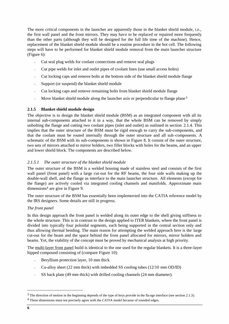
The more critical components in the launcher are apparently those in the blanket shield module, i.e., the first wall panel and the front mirrors. They may have to be replaced or repaired more frequently than the other parts (although they will be designed for the full life time of the machine). Hence, replacement of the blanket shield module should be a routine procedure in the hot cell. The following steps will have to be performed for blanket shield module removal from the main launcher structure (Figure 6):
- Cut seal plug welds for coolant connections and remove seal plugs
- Cut pipe welds for inlet and outlet pipes of coolant lines (use small access holes)
- Cut locking caps and remove bolts at the bottom side of the blanket shield module flange
- Support (or suspend) the blanket shield module
- Cut locking caps and remove remaining bolts from blanket shield module flange
- Move blanket shield module along the launcher axis or perpendicular to flange plane 3
2.1.5 Blanket shield module design The objective is to design the blanket shield module (BSM) as an integrated component with all its internal sub-components attached to it in a way, that the whole BSM can be removed by simply unbolting the flange and cutting two coolant pipes (inlet and outlet) as outlined in section 2.1.4. This implies that the outer structure of the BSM must be rigid enough to carry the sub-components, and that the coolant must be routed internally through the outer structure and all sub -components. A schematic of the BSM with its sub-components is shown in Figure 8. It consist of the outer structure, two sets of mirrors attached to mirror holders, two filler blocks with holes for the beams, and an upper and lower shield block. The components are described below.
2.1.5.1 The outer structure of the blanket shield module The outer structure of the BSM is a welded housing made of stainless steel and consists of the first wall panel (front panel) with a large cut-out for the RF beams, the four side walls making up the double-wall shell, and the flange as interface to the main launcher structure. All elements (except for the flange) are actively cooled via integrated cooling channels and manifolds. Approximate main dimensions4 are give in Figure 9.
The outer structure of the BSM has essentially been implemented into the CATIA reference model by the IRS designers. Some details are still in progress.
The front panel
In this design approach the front panel is welded along its outer edge to the shell giving stiffness to the whole structure. This is in contrast to the design applied to ITER blankets, where the front panel is divided into typically four poloidal segments, each being supported in the central section only and thus allowing thermal bending. The main reason for attempting the welded approach here is the large cut-out for the beam and the space behind the front panel allocated for mirrors, mirror holders and beams. Yet, the viability of the concept must be proved by mechanical analysis at high priority.
The multi-layer front panel build is identical to the one used for the regular blankets. It is a three-layer hipped compound consisting of (compare Figure 10):
- Beryllium protection layer, 10 mm thick
- Cu-alloy sheet (22 mm thick) with imbedded SS cooling tubes (12/10 mm OD/ID)
- SS back plate (49 mm thick) with drilled cooling channels (24 mm diameter).
3 The direction of motion in the beginning depends of the type of keys provide in the fla nge interface (see section 2.1.3). 4 These dimensions must not precisely agree with the CATIA model because of rounded edges.
ECLUPPS Design Activities, Intermediate Report May 2003 – Oct. 2003 7
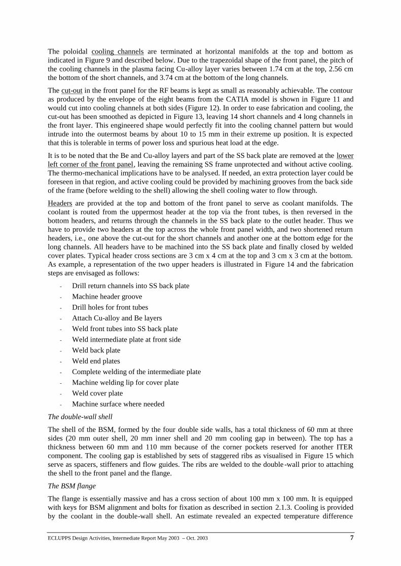
The poloidal cooling channels are terminated at horizontal manifolds at the top and bottom as indicated in Figure 9 and described below. Due to the trapezoidal shape of the front panel, the pitch of the cooling channels in the plasma facing Cu-alloy layer varies between 1.74 cm at the top, 2.56 cm the bottom of the short channels, and 3.74 cm at the bottom of the long channels.
The cut-out in the front panel for the RF beams is kept as small as reasonably achievable. The contour as produced by the envelope of the eight beams from the CATIA model is shown in Figure 11 and would cut into cooling channels at both sides (Figure 12). In order to ease fabrication and cooling, the cut-out has been smoothed as depicted in Figure 13, leaving 14 short channels and 4 long channels in the front layer. This engineered shape would perfectly fit into the cooling channel pattern but would intrude into the outermost beams by about 10 to 15 mm in their extreme up position. It is expected that this is tolerable in terms of power loss and spurious heat load at the edge.
It is to be noted that the Be and Cu-alloy layers and part of the SS back plate are removed at the lower left corner of the front panel, leaving the remaining SS frame unprotected and without active cooling. The thermo-mechanical implications have to be analysed. If needed, an extra protection layer could be foreseen in that region, and active cooling could be provided by machining grooves from the back side of the frame (before welding to the shell) allowing the shell cooling water to flow through.
Headers are provided at the top and bottom of the front panel to serve as coolant manifolds. The coolant is routed from the uppermost header at the top via the front tubes, is then reversed in the bottom headers, and returns through the channels in the SS back plate to the outlet header. Thus we have to provide two headers at the top across the whole front panel width, and two shortened return headers, i.e., one above the cut-out for the short channels and another one at the bottom edge for the long channels. All headers have to be machined into the SS back plate and finally closed by welded cover plates. Typical header cross sections are 3 cm x 4 cm at the top and 3 cm x 3 cm at the bottom. As example, a representation of the two upper headers is illustrated in Figure 14 and the fabrication steps are envisaged as follows:
- Drill return channels into SS back plate - Machine header groove - Drill holes for front tubes - Attach Cu-alloy and Be layers - Weld front tubes into SS back plate - Weld intermediate plate at front side - Weld back plate - Weld end plates - Complete welding of the intermediate plate - Machine welding lip for cover plate - Weld cover plate - Machine surface where needed
The double-wall shell
The shell of the BSM, formed by the four double side walls, has a total thickness of 60 mm at three sides (20 mm outer shell, 20 mm inner shell and 20 mm cooling gap in between). The top has a thickness between 60 mm and 110 mm because of the corner pockets reserved for another ITER component. The cooling gap is established by sets of staggered ribs as visualised in Figure 15 which serve as spacers, stiffeners and flow guides. The ribs are welded to the double -wall prior to attaching the shell to the front panel and the flange.
The BSM flange
The flange is essentially massive and has a cross section of about 100 mm x 100 mm. It is equipped with keys for BSM alignment and bolts for fixation as described in section 2.1.3. Cooling is provided by the coolant in the double-wall shell. An estimate revealed an expected temperature difference
8
within the flange due to neutronics heating of about 13 K (compare section 2.2.2 on page 10), which should be acceptable. The launcher assembly/disassembly concept presented in section 2.1.4 proposes to connect the BSM coolant supply lines to the flange (Figure 6).
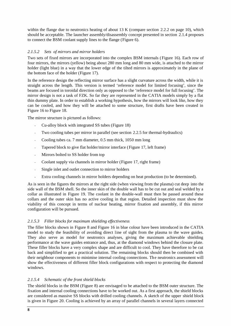
2.1.5.2 Sets of mirrors and mirror holders Two sets of fixed mirrors are incorporated into the complex BSM internals (Figure 16). Each row of four mirrors, the mirrors (yellow) being about 280 mm long and 80 mm wide, is attached to the mirror holder (light blue) in a way that the lower edge of the tilted mirrors is approximately in the plane of the bottom face of the holder (Figure 17).
In the reference design the reflecting mirror surface has a slight curvature across the width, while it is straight across the length. This version is termed ‘reference model for limited focusing’, since the beams are focused in toroidal direction only as opposed to the ‘reference model for full focusing’. The mirror design is not a task of FZK. So far they are represented in the CATIA models simply by a flat thin dummy plate. In order to establish a working hypothesis, how the mirrors will look like, how they can be cooled, and how they will be attached to some structure, first drafts have been created in Figure 16 to Figure 18.
The mirror structure is pictured as follows:
- Cu-alloy block with integrated SS tubes (Figure 18)
- Two cooling tubes per mirror in parallel (see section 2.2.5 for thermal-hydraulics)
- Cooling tubes ca. 7 mm diameter, 0.5 mm thick, 1050 mm long
- Tapered block to give flat holder/mirror interface (Figure 17, left frame)
- Mirrors bolted to SS holder from top
- Coolant supply via channels in mirror holder (Figure 17, right frame)
- Single inlet and outlet connection to mirror holders
- Extra cooling channels in mirror holders depending on heat production (to be determined).
As is seen in the figures the mirrors at the right side (when viewing from the plasma) cut deep into the side wall of the BSM shell. So the inner skin of the double wall has to be cut out and seal welded by a collar as illustrated in Figure 19. The coolant in the double-wall must then be passed around these collars and the outer skin has no active cooling in that region. Detailed inspection must show the viability of this concept in terms of nuclear heating, mirror fixation and assembly, if this mirror configuration will be pursued.
2.1.5.3 Filler blocks for maximum shielding effectiveness The filler blocks shown in Figure 8 and Figure 16 in blue colour have been introduced in the CATIA model to study the feasibility of avoiding direct l ine of sight from the plasma to the wave guides. They also serve as model for neutronics analyses, giving the maximum achievable shielding performance at the wave guides entrance and, thus, at the diamond windows behind the closure plate. These filler blocks have a very complex shape and are difficult to cool. They have therefore to be cut back and simplified to get a practical solution. The remaining blocks should then be combined with their neighbour components to minimise internal cooling connections. The neutronics assessment will show the effectiveness of different filler block configurations with respect to protecting the diamond windows.
2.1.5.4 Schematic of the front shield blocks The shield blocks in the BSM (Figure 8) are envisaged to be attached to the BSM outer structure. The fixation and internal cooling connections have to be worked out. As a first approach, the shield blocks are considered as massive SS blocks with drilled cooling channels. A sketch of the upper shield block is given in Figure 20. Cooling is achieved by an array of parallel channels in several layers connected
ECLUPPS Design Activities, Intermediate Report May 2003 – Oct. 2003 9
by headers at top and bottom. The cooling channel layers are connected in series with the cooling water flowing from the front to the back side. Typical channel dimensions are 16 mm for the vertical channels and 25 mm for the headers and connections. They can be enlarged if needed as to obtain the right water/steel composition. The total volume of the upper block amounts to about 0.04 m3 giving a weight of 250 kg. Detailed thermal-hydraulics have to be investigated, once neutronics results on thermal load distribution are available.
2.2 Estimates related to mechanical and thermal-hydraulic issues
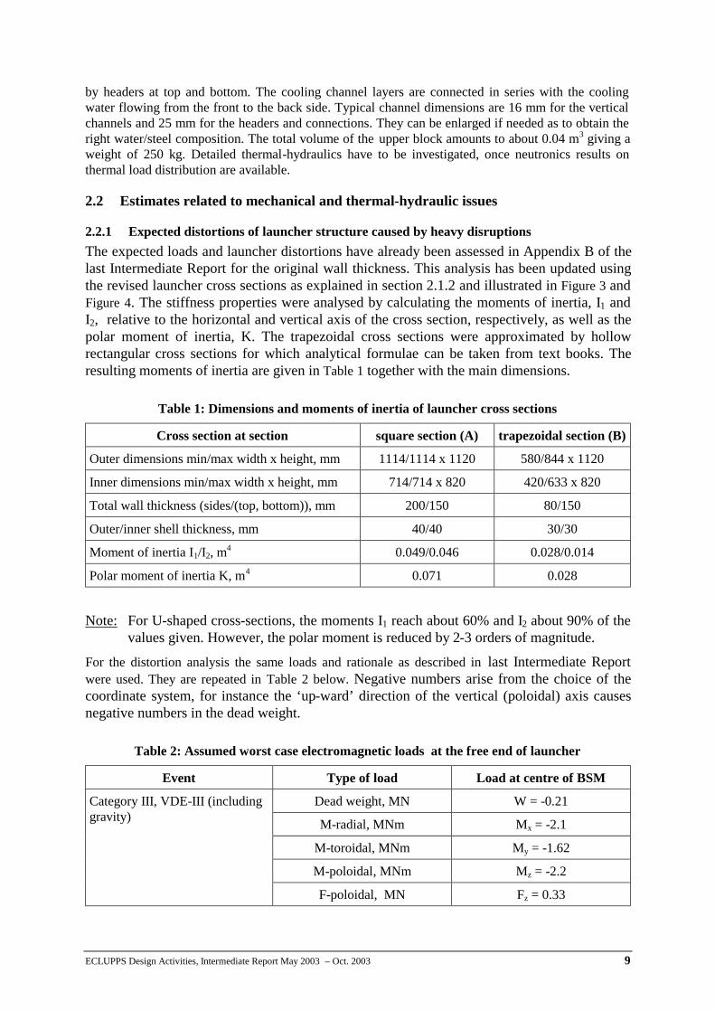
2.2.1 Expected distortions of launcher structure caused by heavy disruptions The expected loads and launcher distortions have already been assessed in Appendix B of the last Intermediate Report for the original wall thickness. This analysis has been updated using the revised launcher cross sections as explained in section 2.1.2 and illustrated in Figure 3 and Figure 4. The stiffness properties were analysed by calculating the moments of inertia, I1 and I2, relative to the horizontal and vertical axis of the cross section, respectively, as well as the polar moment of inertia, K. The trapezoidal cross sections were approximated by hollow rectangular cross sections for which analytical formulae can be taken from text books. The resulting moments of inertia are given in Table 1 together with the main dimensions.
Note: For U-shaped cross-sections, the moments I1 reach about 60% and I2 about 90% of the values given. However, the polar moment is reduced by 2-3 orders of magnitude.
For the distortion analysis the same loads and rationale as described in last Intermediate Report were used. They are repeated in Table 2 below. Negative numbers arise from the choice of the coordinate system, for instance the ‘up-ward’ direction of the vertical (poloidal) axis causes negative numbers in the dead weight.
Table 1: Dimensions and moments of inertia of launcher cross sections
Cross section at section square section (A) trapezoidal section (B)
Outer dimensions min/max width x height, mm 1114/1114 x 1120 580/844 x 1120
Inner dimensions min/max width x height, mm 714/714 x 820 420/633 x 820
Total wall thickness (sides/(top, bottom)), mm 200/150 80/150
Outer/inner shell thickness, mm 40/40 30/30
Moment of inertia I1/I2, m4 0.049/0.046 0.028/0.014
Polar moment of inertia K, m4 0.071 0.028
Table 2: Assumed worst case electromagnetic loads at the free end of launcher
Event Type of load Load at centre of BSM
Dead weight, MN W = -0.21
M-radial, MNm Mx = -2.1
M-toroidal, MNm My = -1.62
M-poloidal, MNm Mz = -2.2
Category III, VDE-III (including gravity)
F-poloidal, MN Fz = 0.33
10
At the present level of approximation, it was decided to assume the relatively short and strong rectangular part of the structure (section A in Figure 4) to be rigid. This implies that the effective length of the beam for all loads (except the dead weight) l1 = 3975 mm +750/2 mm = 4350 mm. For the dead weight we chose l2 = 2000 mm from the fixed end. Using parameters of Table 1 and Table 2, the deflections are found to be -1.5 mm in poloidal, 8.0 mm in toroidal direction and 0.16° twisting angle.
Conclusion of preliminary mechanical analysis
Provided that the present design value of 20 mm for the gap between the inner wall of the vacuum vessel port and the plug would not be restricted by inaccuracies from port manufacturing and alignment, the launcher structure with its new dimensions is found to be adequately stiff to tolerate extreme external loads. It is obvious from our assessment, that interlocking structures would be required for any opening of the main structure (like the maintenance lid), since any weakening of the torsional stiffness, even by only one order of magnitude, would result in critical torsion angles above 1°. A more firm mechanical analysis by FE methods is planned, including reassessment of the electromagnetic disruption loads.
2.2.2 Temperature difference in a slab with internal heat load Most of the in-vessel components of the UPP need to be actively cooled because of the volumetric heat produced by neutrons and gamma radiation. In order to get an idea of what temperature difference would occur in some structure that is cooled at one side and adiabatic at the other side, a simple slab model is considered here with constant internal heat.
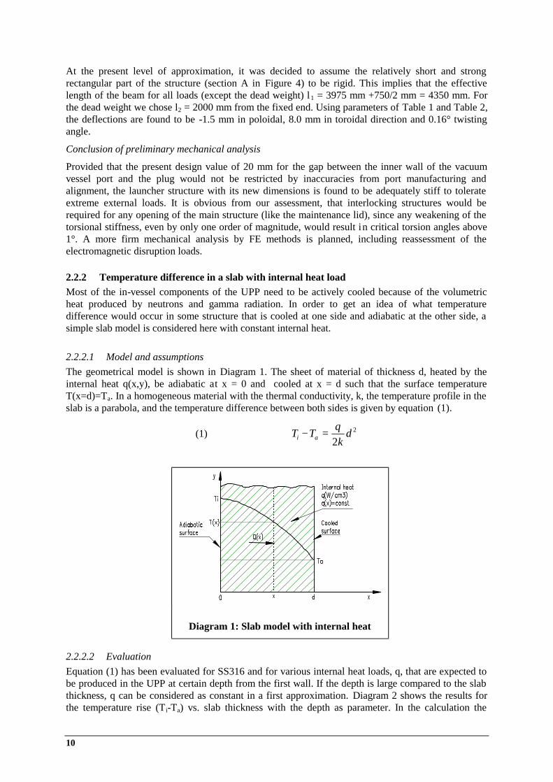
2.2.2.1 Model and assumptions The geometrical model is shown in Diagram 1. The sheet of material of thickness d, heated by the internal heat q(x,y), be adiabatic at x = 0 and cooled at x = d such that the surface temperature T(x=d)=Ta. In a homogeneous material with the thermal conductivity, k, the temperature profile in the slab is a parabola, and the temperature difference between both sides is given by equation (1).
(1) 2
2d
kqTT ai =−
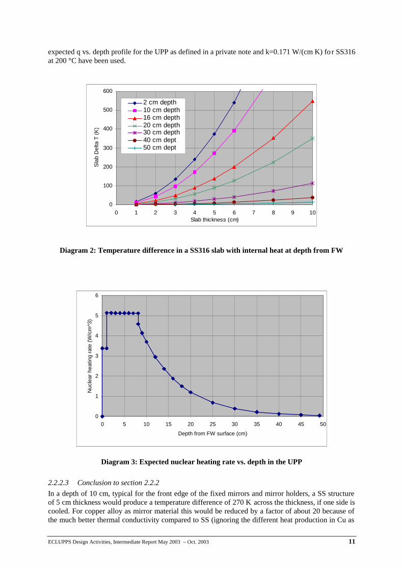
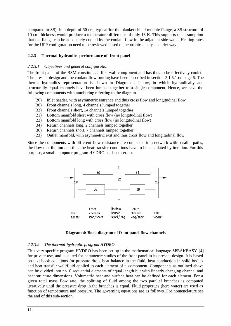
2.2.2.2 Evaluation Equation (1) has been evaluated for SS316 and for various internal heat loads, q, that are expected to be produced in the UPP at certain depth from the first wall. If the depth is large compared to the slab thickness, q can be considered as constant in a first approximation. Diagram 2 shows the results for the temperature rise (T i-Ta) vs. slab thickness with the depth as parameter. In the calculation the
Diagram 1: Slab model with internal heat
ECLUPPS Design Activities, Intermediate Report May 2003 – Oct. 2003 11
expected q vs. depth profile for the UPP as defined in a private note and k=0.171 W/(cm K) fo r SS316 at 200 °C have been used.
2.2.2.3 Conclusion to section 2.2.2 In a depth of 10 cm, typical for the front edge of the fixed mirrors and mirror holders, a SS structure of 5 cm thickness would produce a temperature difference of 270 K across the thickness, if one side is cooled. For copper alloy as mirror material this would be reduced by a factor of about 20 because of the much better thermal conductivity compared to SS (ignoring the different heat production in Cu as
Diagram 2: Temperature difference in a SS316 slab with internal heat at depth from FW
0
1
2
3
4
5
6
0 5 10 15 20 25 30 35 40 45 50
Depth from FW surface (cm)
Nuc
lear
hea
ting
rate
(W/c
m^3
)
Diagram 3: Expected nuclear heating rate vs. depth in the UPP
0
100
200
300
400
500
600
0 1 2 3 4 5 6 7 8 9 10Slab thickness (cm)
Slab
Del
ta T
(K)
2 cm depth10 cm depth16 cm depth20 cm depth30 cm depth40 cm dept50 cm dept
12
compared to SS). In a depth of 50 cm, typical for the blanket shield module flange, a SS structure of 10 cm thickness would produce a temperature difference of only 13 K. This supports the assumption that the flange can be adequately cooled by the coolant flow in the adjacent side walls. Heating rates for the UPP configuration need to be reviewed based on neutronics analysis under way.
2.2.3 Thermal-hydraulics performance of front panel
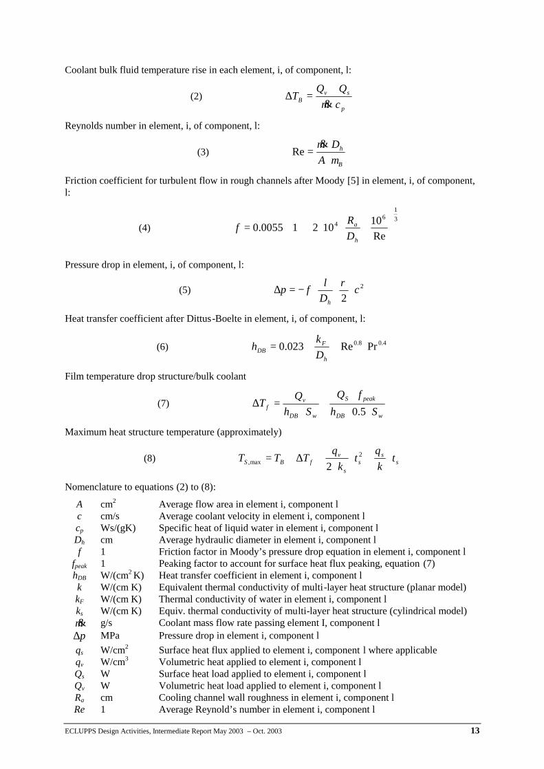
2.2.3.1 Objectives and general configuration The front panel of the BSM constitutes a first wall component and has thus to be effectively cooled. The present design and the coolant flow routing have been described in section 2.1.5.1 on page 6. The thermal-hydraulics representation is shown in Diagram 4 below, in which hydraulically and structurally equal channels have been lumped together to a single component. Hence, we have the following components with numbering referring to the diagram.
(20) Inlet header, with asymmetric entrance and thus cross flow and longitudinal flow (30) Front channels long, 4 channels lumped together (32) Front channels short, 14 channels lumped together (21) Bottom manifold short with cross flow (no longitudinal flow) (22) Bottom manifold long with cross flow (no longitudinal flow) (34) Return channels long, 2 channels lumped together (36) Return channels short, 7 channels lumped together (23) Outlet manifold, with asymmetric exit and thus cross flow and longitudinal flow
Since the components with different flow resistance are connected in a network with parallel paths, the flow distribution and thus the heat transfer conditions have to be calculated by iteration. For this purpose, a small computer program HYDRO has been set up.
2.2.3.2 The thermal-hydraulic program HYDRO This very specific program HYDRO has been set up in the mathematical language SPEAKEASY [4] for private use, and is suited for parametric studies of the front panel in its present design. It is based on text book equations for pressure drop, heat balance in the fluid, heat conduction in solid bodies and heat transfer wall/fluid applied to each element of a component. Components as outlined above can be divided into n<10 sequential elements of equal length but with linearly changing channel and heat structure dimensions. Volumetric heat and surface heat can be defined for each element. For a given total mass flow rate, the splitting of fluid among the two parallel branches is computed iteratively until the pressure drop in the branches is equal. Fluid properties (here water) are used as function of temperature and pressure. The governing equations are as follows. For nomenclature see the end of this sub-section.
Diagram 4: Bock diagram of front panel flow channels
ECLUPPS Design Activities, Intermediate Report May 2003 – Oct. 2003 13
Coolant bulk fluid temperature rise in each element, i, of component, l:
(2) p
svB cm
QQT
⋅+
=∆&
Reynolds number in element, i, of component, l:
(3) B
h
ADmµ⋅
⋅=
&Re
Friction coefficient for turbulent flow in rough channels after Moody [5] in element, i, of component, l:
(4)
+⋅⋅+⋅=
31
64
Re1010210055.0
h
a
DRf
Pressure drop in element, i, of component, l:
(5) 2
2c
Dlfp
h
⋅⋅⋅−=∆ρ
Heat transfer coefficient after Dittus-Boelte in element, i, of component, l:
(6) 4.08.0 PrRe023.0 ⋅⋅
⋅=
h
FDB D
kh
Film temperature drop structure/bulk coolant
(7) wDB
peakS
wDB
vf Sh
fQSh
QT⋅⋅
⋅+
⋅=∆
5.0
Maximum heat structure temperature (approximately)
(8) ss
ss
vfBS t
kq
tk
qTTT ⋅+⋅
⋅+∆+= 2
max, 2
Nomenclature to equations (2) to (8):
A cm2 Average flow area in element i, component l c cm/s Average coolant velocity in element i, component l cp Ws/(gK) Specific heat of liquid water in element i, component l Dh cm Average hydraulic diameter in element i, component l f 1 Friction factor in Moody’s pressure drop equation in element i, component l
fpeak 1 Peaking factor to account for surface heat flux peaking, equation (7) hDB W/(cm2 K) Heat transfer coefficient in element i, component l k W/(cm K) Equivalent thermal conductivity of multi-layer heat structure (planar model) kF W/(cm K) Thermal conductivity of water in element i, component l ks W/(cm K) Equiv. thermal conductivity of multi-layer heat structure (cylindrical model) m& g/s Coolant mass flow rate passing element I, component l p∆ MPa Pressure drop in element i, component l
qs W/cm2 Surface heat flux applied to element i, component l where applicable qv W/cm3 Volumetric heat applied to element i, component l Qs W Surface heat load applied to element i, component l Qv W Volumetric heat load applied to element i, component l Ra cm Cooling channel wall roughness in element i, component l Re 1 Average Reynold’s number in element i, component l
14
Sw cm2 Wetted coolant channel surface in element i, component l ts cm Wall thickness of HS towards heated surface of element i, component l TB °C Average bulk coolant temperature in element i. component l
BT∆ °C Coolant temperature rise in element i, component l
fT∆ °C Film temperature drop structure/bulk coolant in element i, component l
Bµ g/(cm s) Dyn. viscosity of liquid water at bulk temperature in element i, component l
Bρ g/cm3 Average water density at bulk coolant temperature in element i, component l
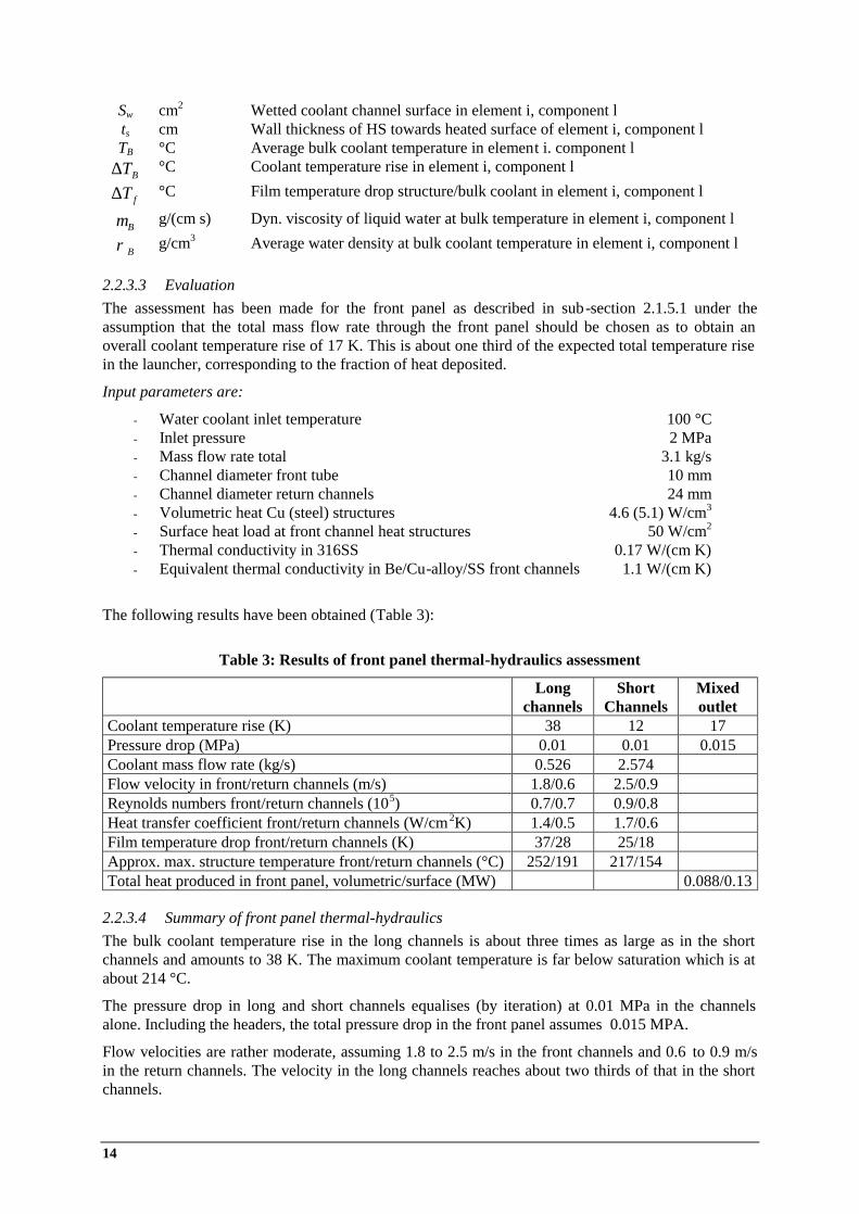
2.2.3.3 Evaluation The assessment has been made for the front panel as described in sub-section 2.1.5.1 under the assumption that the total mass flow rate through the front panel should be chosen as to obtain an overall coolant temperature rise of 17 K. This is about one third of the expected total temperature rise in the launcher, corresponding to the fraction of heat deposited.
Input parameters are:
- Water coolant inlet temperature 100 °C - Inlet pressure 2 MPa - Mass flow rate total 3.1 kg/s - Channel diameter front tube 10 mm - Channel diameter return channels 24 mm - Volumetric heat Cu (steel) structures 4.6 (5.1) W/cm3 - Surface heat load at front channel heat structures 50 W/cm2 - Thermal conductivity in 316SS 0.17 W/(cm K) - Equivalent thermal conductivity in Be/Cu-alloy/SS front channels 1.1 W/(cm K)
The following results have been obtained (Table 3):
2.2.3.4 Summary of front panel thermal-hydraulics The bulk coolant temperature rise in the long channels is about three times as large as in the short channels and amounts to 38 K. The maximum coolant temperature is far below saturation which is at about 214 °C.
The pressure drop in long and short channels equalises (by iteration) at 0.01 MPa in the channels alone. Including the headers, the total pressure drop in the front panel assumes 0.015 MPA.
Flow velocities are rather moderate, assuming 1.8 to 2.5 m/s in the front channels and 0.6 to 0.9 m/s in the return channels. The velocity in the long channels reaches about two thirds of that in the short channels.
Table 3: Results of front panel thermal-hydraulics assessment
Long channels
Short Channels
Mixed outlet
Coolant temperature rise (K) 38 12 17 Pressure drop (MPa) 0.01 0.01 0.015 Coolant mass flow rate (kg/s) 0.526 2.574 Flow velocity in front/return channels (m/s) 1.8/0.6 2.5/0.9 Reynolds numbers front/return channels (105) 0.7/0.7 0.9/0.8 Heat transfer coefficient front/return channels (W/cm2K) 1.4/0.5 1.7/0.6 Film temperature drop front/return channels (K) 37/28 25/18 Approx. max. structure temperature front/return channels (°C) 252/191 217/154 Total heat produced in front panel, volumetric/surface (MW) 0.088/0.13
ECLUPPS Design Activities, Intermediate Report May 2003 – Oct. 2003 15
Heat transfer coefficients are adequate in the front channels (1.4 to 1.7 W/(cm 2K)) but a factor of three lower in the return channels due to the low flow velocity there. Nevertheless, the film temperature drop remains reasonable and is even smaller in the return channels because of the smaller heat flux.
The maximum temperature in the structure is obtained with 252 °C at the end of the long channels (at the plasma facing beryllium surface). The short channels stay 35 °C lower. Temperatures in the 316SS structure are uncritical remaining below 200 °C.
The total heat deposited in the front panel from volumetric and surface heating amounts to 0.218 MW at present input data (see sub-section 2.2.3.3).
Overall, the presented cooling concept of the front panel proved to be feasible with respect to temperature limits, flow distribution and pressure drop. It leaves margin for adjustments, once better data on nuclear heating will be available. Refined thermal-hydraulics and thermo-mechanical analyses are needed when the design has been settled.
2.2.4 Thermal-hydraulics performance of double-wall BSM shell
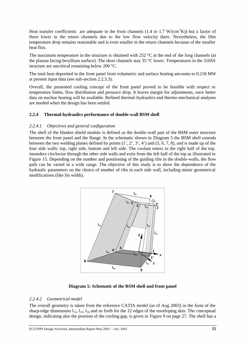
2.2.4.1 Objectives and general configuration The shell of the blanket shield module is defined as the double-wall part of the BSM outer structure between the front panel and the flange. In the schematic shown in Diagram 5 the BSM shell extends between the two welding planes defined by points (1’, 2’, 3’, 4’) and (5, 6, 7, 8), and is made up of the four side walls: top, right side, bottom and left side. The coolant enters to the right half of the top, meanders clockwise through the other side walls and exits from the left half of the top as illustrated in Figure 15. Depending on the number and positioning of the guiding ribs in the double-walls, the flow path can be varied in a wide range. The objective of this study is to show the dependence of the hydraulic parameters on the choice of number of ribs in each side wall, including minor geometrical modifications (like fin width).
2.2.4.2 Geometrical model The overall geometry is taken from the reference CATIA model (as of Aug 2003) in the form of the sharp-edge dimensions l12, l23, l34 and so forth for the 12 edges of the enveloping skin. The conceptual design, indicating also the position of the cooling gap, is given in Figure 9 on page 27. The shell has a
Diagram 5: Schematic of the BSM shell and front panel
l37
l23
l12
l12
l78
l58
l15
l48
l67
l26
l56
1
23
4
5
67
81'
2'3'
4'x
y
z
l14
l34
16
total thickness of 60 mm at three sides (20 mm outer shell, 20 mm inner shell and 20 mm coo ling gap in between). The top has a thickness between 60 mm and 110 mm because of the corner pockets.
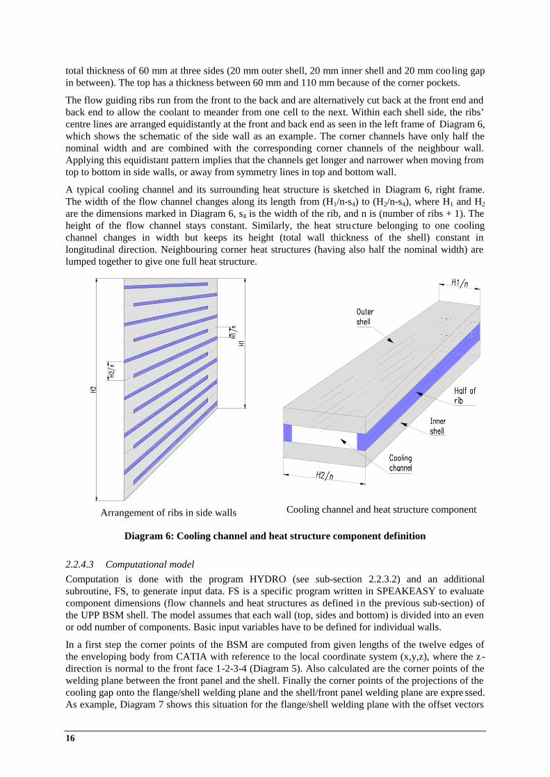
The flow guiding ribs run from the front to the back and are alternatively cut back at the front end and back end to allow the coolant to meander from one cell to the next. Within each shell side, the ribs’ centre lines are arranged equidistantly at the front and back end as seen in the left frame of Diagram 6, which shows the schematic of the side wall as an example. The corner channels have only half the nominal width and are combined with the corresponding corner channels of the neighbour wall. Applying this equidistant pattern implies that the channels get longer and narrower when moving from top to bottom in side walls, or away from symmetry lines in top and bottom wall.
A typical cooling channel and its surrounding heat structure is sketched in Diagram 6, right frame. The width of the flow channel changes along its length from (H1/n-s4) to (H2/n-s4), where H1 and H2 are the dimensions marked in Diagram 6, s4 is the width of the rib, and n is (number of ribs + 1). The height of the flow channel stays constant. Similarly, the heat structure belonging to one cooling channel changes in width but keeps its height (total wall thickness of the shell) constant in longitudinal direction. Neighbouring corner heat structures (having also half the nominal width) are lumped together to give one full heat structure.
2.2.4.3 Computational model Computation is done with the program HYDRO (see sub-section 2.2.3.2) and an additional subroutine, FS, to generate input data. FS is a specific program written in SPEAKEASY to evaluate component dimensions (flow channels and heat structures as defined in the previous sub-section) of the UPP BSM shell. The model assumes that each wall (top, sides and bottom) is divided into an even or odd number of components. Basic input variables have to be defined for individual walls.
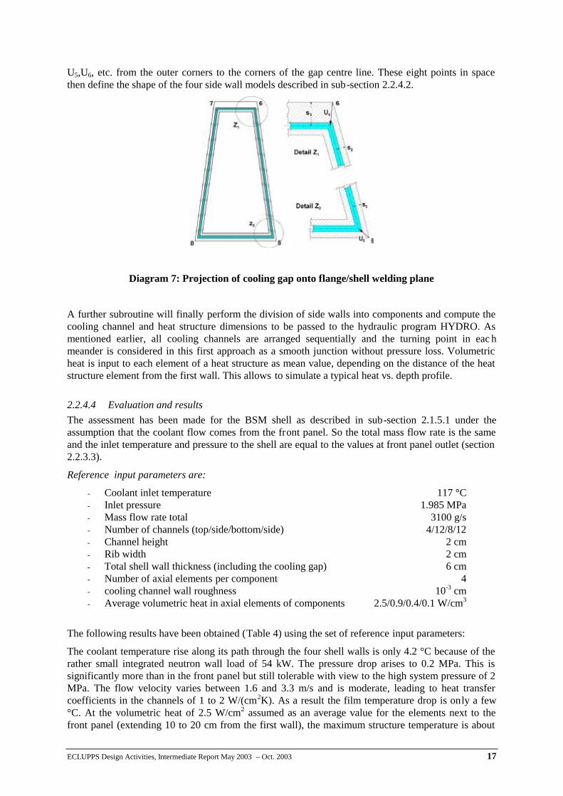
In a first step the corner points of the BSM are computed from given lengths of the twelve edges of the enveloping body from CATIA with reference to the local coordinate system (x,y,z), where the z-direction is normal to the front face 1-2-3-4 (Diagram 5). Also calculated are the corner points of the welding plane between the front panel and the shell. Finally the corner points of the projections of the cooling gap onto the flange/shell welding plane and the shell/front panel welding plane are expre ssed. As example, Diagram 7 shows this situation for the flange/shell welding plane with the offset vectors
Arrangement of ribs in side walls
Cooling channel and heat structure component
Diagram 6: Cooling channel and heat structure component definition
ECLUPPS Design Activities, Intermediate Report May 2003 – Oct. 2003 17
U5,U6, etc. from the outer corners to the corners of the gap centre line. These eight points in space then define the shape of the four side wall models described in sub-section 2.2.4.2.
A further subroutine will finally perform the division of side walls into components and compute the cooling channel and heat structure dimensions to be passed to the hydraulic program HYDRO. As mentioned earlier, all cooling channels are arranged sequentially and the turning point in eac h meander is considered in this first approach as a smooth junction without pressure loss. Volumetric heat is input to each element of a heat structure as mean value, depending on the distance of the heat structure element from the first wall. This allows to simulate a typical heat vs. depth profile.
2.2.4.4 Evaluation and results The assessment has been made for the BSM shell as described in sub-section 2.1.5.1 under the assumption that the coolant flow comes from the front panel. So the total mass flow rate is the same and the inlet temperature and pressure to the shell are equal to the values at front panel outlet (section 2.2.3.3).
Reference input parameters are:
The following results have been obtained (Table 4) using the set of reference input parameters:
The coolant temperature rise along its path through the four shell walls is only 4.2 °C because of the rather small integrated neutron wall load of 54 kW. The pressure drop arises to 0.2 MPa. This is significantly more than in the front panel but still tolerable with view to the high system pressure of 2 MPa. The flow velocity varies between 1.6 and 3.3 m/s and is moderate, leading to heat transfer coefficients in the channels of 1 to 2 W/(cm2K). As a result the film temperature drop is only a few °C. At the volumetric heat of 2.5 W/cm2 assumed as an average value for the elements next to the front panel (extending 10 to 20 cm from the first wall), the maximum structure temperature is about
Diagram 7: Projection of cooling gap onto flange/shell welding plane
- Coolant inlet temperature 117 °C - Inlet pressure 1.985 MPa - Mass flow rate total 3100 g/s - Number of channels (top/side/bottom/side) 4/12/8/12 - Channel height 2 cm - Rib width 2 cm - Total shell wall thickness (including the cooling gap) 6 cm - Number of axial elements per component 4 - cooling channel wall roughness 10-3 cm - Average volumetric heat in axial elements of components 2.5/0.9/0.4/0.1 W/cm3
18
35 °C above the coolant temperature, i.e., 155 °C. Since the heat gradient in this region is steep, the real maximum will be around 200 °C. Although this temperature level is uncritical, detailed FE analysis, in connection with the front panel, must show the impact on thermal stresses.
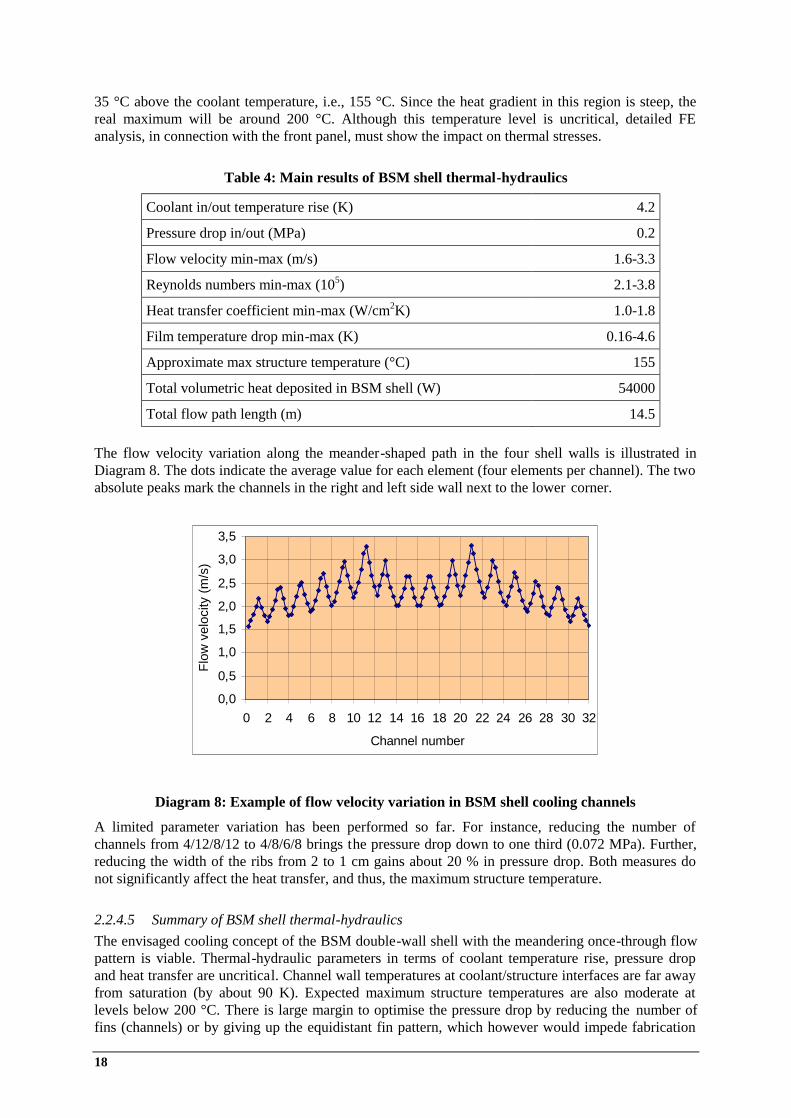
The flow velocity variation along the meander-shaped path in the four shell walls is illustrated in Diagram 8. The dots indicate the average value for each element (four elements per channel). The two absolute peaks mark the channels in the right and left side wall next to the lower corner.
A limited parameter variation has been performed so far. For instance, reducing the number of channels from 4/12/8/12 to 4/8/6/8 brings the pressure drop down to one third (0.072 MPa). Further, reducing the width of the ribs from 2 to 1 cm gains about 20 % in pressure drop. Both measures do not significantly affect the heat transfer, and thus, the maximum structure temperature.
2.2.4.5 Summary of BSM shell thermal-hydraulics The envisaged cooling concept of the BSM double-wall shell with the meandering once-through flow pattern is viable. Thermal-hydraulic parameters in terms of coolant temperature rise, pressure drop and heat transfer are uncritical. Channel wall temperatures at coolant/structure interfaces are far away from saturation (by about 90 K). Expected maximum structure temperatures are also moderate at levels below 200 °C. There is large margin to optimise the pressure drop by reducing the number of fins (channels) or by giving up the equidistant fin pattern, which however would impede fabrication
Table 4: Main results of BSM shell thermal-hydraulics
Coolant in/out temperature rise (K) 4.2
Pressure drop in/out (MPa) 0.2
Flow velocity min-max (m/s) 1.6-3.3
Reynolds numbers min-max (105) 2.1-3.8
Heat transfer coefficient min-max (W/cm2K) 1.0-1.8
Film temperature drop min-max (K) 0.16-4.6
Approximate max structure temperature (°C) 155
Total volumetric heat deposited in BSM shell (W) 54000
Total flow path length (m) 14.5
Diagram 8: Example of flow velocity variation in BSM shell cooling channels
0,0
0,5
1,0
1,5
2,0
2,5
3,0
3,5
0 2 4 6 8 10 12 14 16 18 20 22 24 26 28 30 32
Channel number
Flow
vel
ocity
(m/s
)

ECLUPPS Design Activities, Intermediate Report May 2003 – Oct. 2003 19
aspects. This assessment does not account for imperfections such as the collision of the front mirrors (see sub-section 2.1.5.2 on page 8).
2.2.5 Thermal-hydraulics performance of front mirrors
2.2.5.1 Objectives and configuration The rationale of this scoping study has already been described in sub-section 2.1.5.2. The preliminary mirror design is intended as a working hypothesis that should help to identify critical points and to establish interfaces to other cooling issues of the BSM components.
2.2.5.2 Geometrical model The geometry and main dimensions are shown in Figure 18, where the Cu-alloy structure is assumed as a block with constant thickness (as opposed to the wedge shape proposed in Figure 17). The expected surface heat load profile is assumed to be Gaussian and is axis-symmetric relative to the beam axis. Therefore the projection onto the inclined mirror surface is elliptical. The intersection point of the beam axis can vary along the mirror centre line such that in the extreme position only one end (about one half of the mirror) will be heated.
The thermal-hydraulic model is a simplified one-dimensional representation of one mirror. Each of the two staggered spiral cooling channels and pertaining heat structures are simulated by a straight component as sketched in Diagram 9, conserving relevant quantities, like mass, unit cell cross section, and channel length. The whole component is then divided into n axial elements of equal length. A volumetric heat rate (with the same value for the Cu-alloy matrix and the SS316 tube) and a surface heat flux to the bottom face can be applied to individual elements. In this case we assign a heat flux to the first element q1=qpeak (where qpeak is the peak heat flux at the mirror) and q rest to the rest, thereby having one element seeing the peak heat flux and the other elements balancing for the desired total surface heat load to the mirror for energy conservation. Hence, the intention here i s only to look at the element with the peak heat load with focus on local effects (flow velocity, heat transfer coefficient, film temperature drop, maximum structure temperature), while the rest serves to determine gross effects (coolant temperature rise, pressure drop, integrated volumetric and surface heat load).
A planar single-layer heat conduction model with an equivalent thermal conductivity is used to estimate the maximum structure temperature occurring at the heated surface. Computation is done with the program HYDRO (see sub-section 2.2.3.2) and an additional subroutine to generate input data.
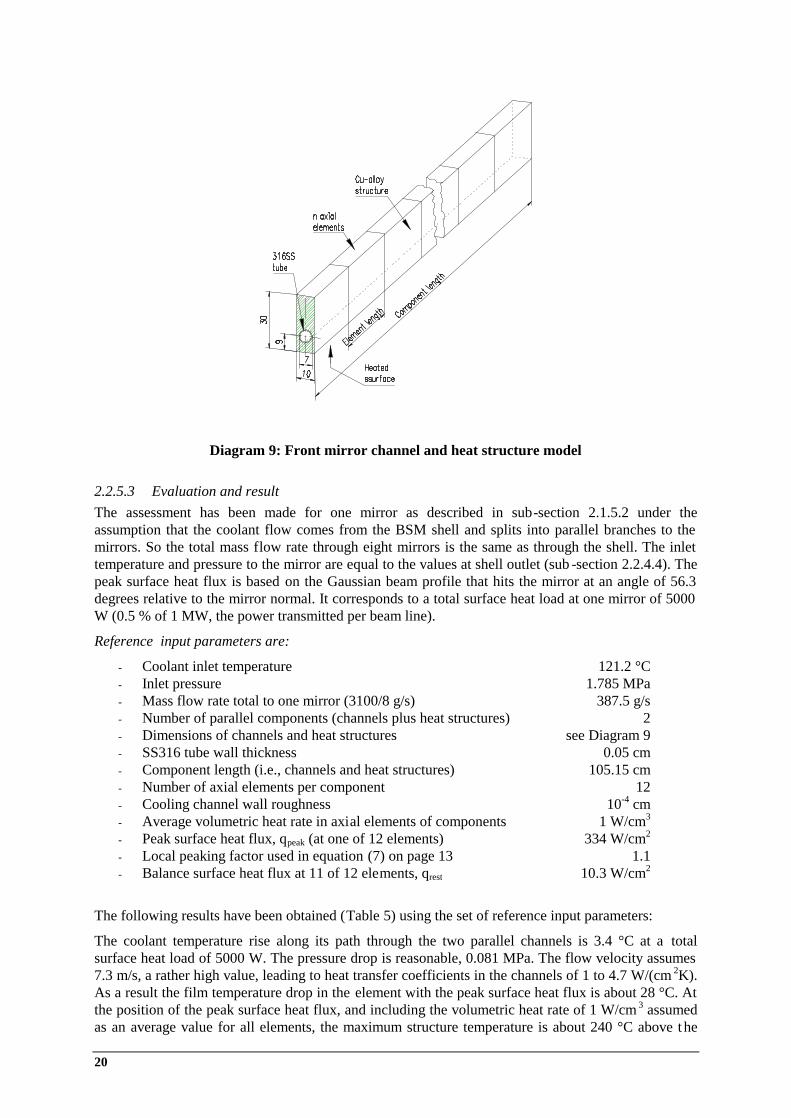
20
2.2.5.3 Evaluation and result The assessment has been made for one mirror as described in sub-section 2.1.5.2 under the assumption that the coolant flow comes from the BSM shell and splits into parallel branches to the mirrors. So the total mass flow rate through eight mirrors is the same as through the shell. The inlet temperature and pressure to the mirror are equal to the values at shell outlet (sub -section 2.2.4.4). The peak surface heat flux is based on the Gaussian beam profile that hits the mirror at an angle of 56.3 degrees relative to the mirror normal. It corresponds to a total surface heat load at one mirror of 5000 W (0.5 % of 1 MW, the power transmitted per beam line).
The following results have been obtained (Table 5) using the set of reference input parameters:
The coolant temperature rise along its path through the two parallel channels is 3.4 °C at a total surface heat load of 5000 W. The pressure drop is reasonable, 0.081 MPa. The flow velocity assumes 7.3 m/s, a rather high value, leading to heat transfer coefficients in the channels of 1 to 4.7 W/(cm 2K). As a result the film temperature drop in the element with the peak surface heat flux is about 28 °C. At the position of the peak surface heat flux, and including the volumetric heat rate of 1 W/cm 3 assumed as an average value for all elements, the maximum structure temperature is about 240 °C above t he
Diagram 9: Front mirror channel and heat structure model
Reference input parameters are:
- Coolant inlet temperature 121.2 °C - Inlet pressure 1.785 MPa - Mass flow rate total to one mirror (3100/8 g/s) 387.5 g/s - Number of parallel components (channels plus heat structures) 2 - Dimensions of channels and heat structures see Diagram 9 - SS316 tube wall thickness 0.05 cm - Component length (i.e., channels and heat structures) 105.15 cm - Number of axial elements per component 12 - Cooling channel wall roughness 10-4 cm - Average volumetric heat rate in axial elements of components 1 W/cm3 - Peak surface heat flux, qpeak (at one of 12 elements) 334 W/cm2
- Local peaking factor used in equation (7) on page 13 1.1 - Balance surface heat flux at 11 of 12 elements, qrest 10.3 W/cm2
ECLUPPS Design Activities, Intermediate Report May 2003 – Oct. 2003 21
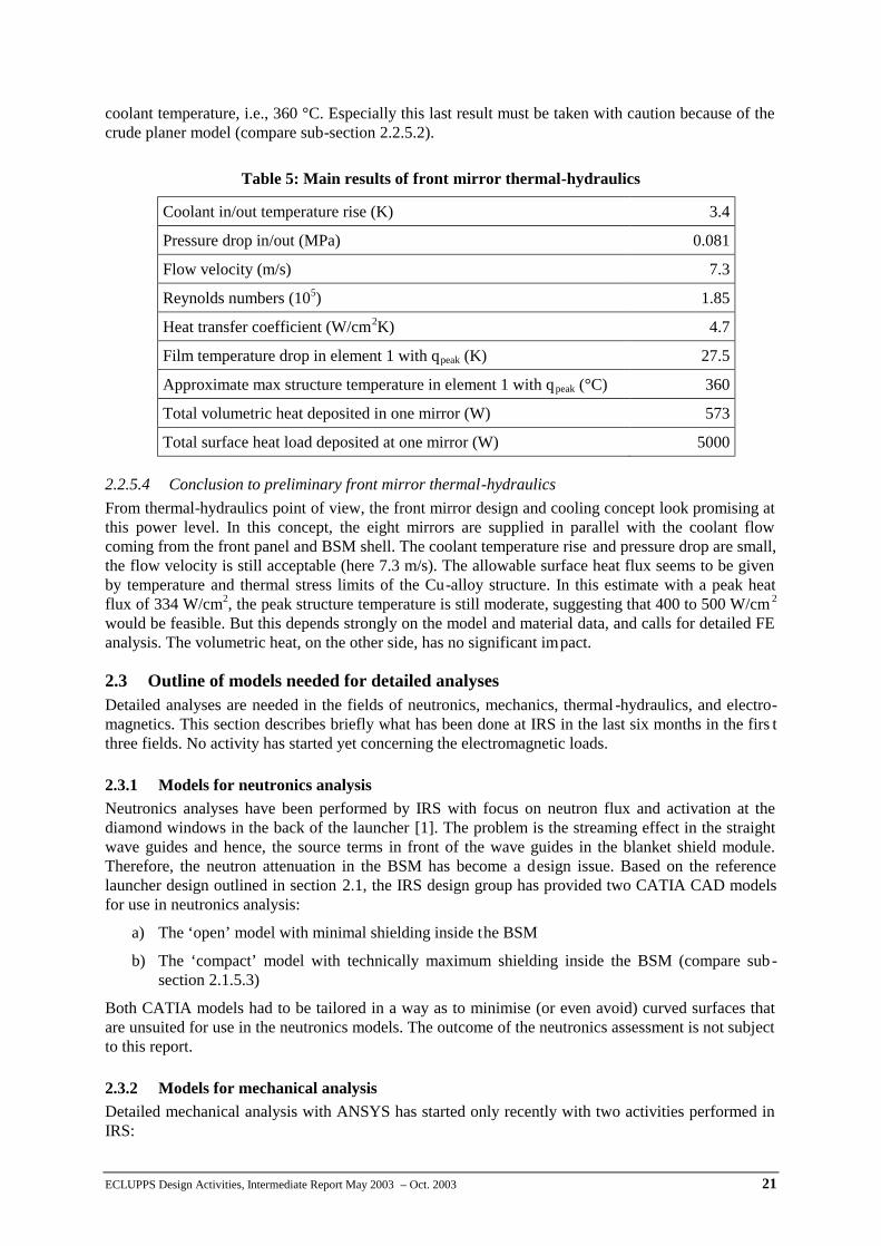
coolant temperature, i.e., 360 °C. Especially this last result must be taken with caution because of the crude planer model (compare sub-section 2.2.5.2).
2.2.5.4 Conclusion to preliminary front mirror thermal-hydraulics From thermal-hydraulics point of view, the front mirror design and cooling concept look promising at this power level. In this concept, the eight mirrors are supplied in parallel with the coolant flow coming from the front panel and BSM shell. The coolant temperature rise and pressure drop are small, the flow velocity is still acceptable (here 7.3 m/s). The allowable surface heat flux seems to be given by temperature and thermal stress limits of the Cu-alloy structure. In this estimate with a peak heat flux of 334 W/cm2, the peak structure temperature is still moderate, suggesting that 400 to 500 W/cm 2 would be feasible. But this depends strongly on the model and material data, and calls for detailed FE analysis. The volumetric heat, on the other side, has no significant impact.
2.3 Outline of models needed for detailed analyses Detailed analyses are needed in the fields of neutronics, mechanics, thermal -hydraulics, and electro-magnetics. This section describes briefly what has been done at IRS in the last six months in the firs t three fields. No activity has started yet concerning the electromagnetic loads.
2.3.1 Models for neutronics analysis Neutronics analyses have been performed by IRS with focus on neutron flux and activation at the diamond windows in the back of the launcher [1]. The problem is the streaming effect in the straight wave guides and hence, the source terms in front of the wave guides in the blanket shield module. Therefore, the neutron attenuation in the BSM has become a design issue. Based on the reference launcher design outlined in section 2.1, the IRS design group has provided two CATIA CAD models for use in neutronics analysis:
a) The ‘open’ model with minimal shielding inside the BSM
b) The ‘compact’ model with technically maximum shielding inside the BSM (compare sub-section 2.1.5.3)
Both CATIA models had to be tailored in a way as to minimise (or even avoid) curved surfaces that are unsuited for use in the neutronics models. The outcome of the neutronics assessment is not subject to this report.
2.3.2 Models for mechanical analysis Detailed mechanical analysis with ANSYS has started only recently with two activities performed in IRS:
Table 5: Main results of front mirror thermal-hydraulics
Coolant in/out temperature rise (K) 3.4
Pressure drop in/out (MPa) 0.081
Flow velocity (m/s) 7.3
Reynolds numbers (105) 1.85
Heat transfer coefficient (W/cm2K) 4.7
Film temperature drop in element 1 with qpeak (K) 27.5
Approximate max structure temperature in element 1 with qpeak (°C) 360
Total volumetric heat deposited in one mirror (W) 573
Total surface heat load deposited at one mirror (W) 5000

22
a) Parametric study of temperature distribution in front mirrors
b) Thermo-mechanical analysis of front panel
Task (a) is very limited and shall prove, by FE methods, the findings from the preliminary layout and thermal-hydraulic assessment of the front mirrors described in section 2.2.5.
Task (b) is more demanding (compare sub-section 2.1.5.1). In a first step the transfer of the front panel model from CATIA to ANSYS is being attempted. The adjustments needed are under discussion.
2.3.3 Models for thermal-hydraulics analysis Thermal-hydraulics analyses have been performed so far by the author, applying one-dimensional models only. This seems to be adequate at the present conceptual design status. Three models have been developed and investigated and are described in detail in this report:
a) Thermal-hydraulics model of the front panel (compare section 2.2.3)
b) Thermal-hydraulics model of the blanket shield module double-wall (compare section 2.2.4)
c) Thermal-hydraulics model of the front mirror (compare section 2.2.5)
This work has to be continued on this one-dimensional level with other launcher components, in particular with focus on the main launcher structure. The use of integrated and licensed thermal -hydraulics codes will be needed as the conceptual design becomes stable.
2.4 Collaboration with other groups involved in the project Within this contract between FZK and the author, the main objective of collaboration is to establish a link between the design group at IRS and the person responsible for the EC H&CD, Dr. R. Heidinger, IMF I. A large number of small groups discussions (about one per week) took place with experts from IRS and IMF. In addition, a two-days Working Group Meeting was arranged by IMF with external experts from CRPP Lausanne and FOM Rijnhuizen with contributions by the author. Another meeting on launcher design issues was held at Garching on September 17 2003 with experts from ITER JWS.
Support and view graphs were also delivered to the formal Progress Report Meeting on October 8, 2003 in Rijnhuizen. Here, reports were given by CNR Milano, CRPP Lausanne, IFP Stuttgart, FOM Rijnhuizen and FZK Karlsruhe. The launcher design development is closely connected to the physics analysis for which recent results on CD efficiency & NTM stabilisation were presented by the Participating Physics Groups: IPP Garching, FOM Rijnhuizen, CNR Milano and UKAEE Culham.
2.5 Documents prepared during the reporting period The following list contains the documents related to the UPP design, that have been prepared at FZK during the period May – October 2003. The list includes publications, reports, view graphs presented at meetings, and internal notes which can be found in the document library.
2.5.1 Publications U. Fischer et.al.: Analysis of fast neutron streaming in the waveguide channels of the ECRH system in the ITER upper port, IAEA TM on ECRH Phys. and Tech. for ITER, July 14-16, 2003, Kloster Seeon, Germany.
R. Heidinger, G. Hailfinger, V. Heinzel, K. Kleefeldt, E. Stratmanns: Conceptual Design Studies for the Blanket Shield Module and the Main Structure of the Upper Port Plug, IAEA TM on ECRH Phys. and Tech. for ITER, July 14-16, 2003, Kloster Seeon, Germany.
K. Kleefeldt: Conceptual design for the blanket shield module and the main structure of the upper port plug, view graphs prepared fir the IAEA TM on ECRH Phys. and Tech. for ITER, July 14-16, 2003, Kloster Seeon, Germany.
ECLUPPS Design Activities, Intermediate Report May 2003 – Oct. 2003 23
2.5.2 Reports This Intermediate Report (not yet available in the document library)
2.5.3 Workshops R.Heidinger et.al.: Design and analysis of the upper EC launcher for ITER: Windows and main structural components, US-JA workshop on RF Heating Technology and the 6th EU-JA workshop on RF Antenna and related Technology, Tokai, 25-26 September, 2003
K. Kleefeldt et.al.: Blanket shield module design, Presentation at the ECLUPPS Working Group Meeting on 170 GHz beam line Mock-up, Karlsruhe, Sep 15-16, 2003.
2.5.4 Minutes and notes R. Heidinger: Minutes of the meeting on the upper launcher design, ITER JWS Garching, 17 – Sep 2003.
R. Heidinger: Status of ECRH upper launcher design and their implication on port configuration taking into accout new results from ongoing physical analysis, FZK/IMF internal note, ECLUPPS Note 310_PortConfig (Oct. 2003).
R. Heidinger: Dimensions of wall structure of the Upper Port Plug, ECLUPPS Note: 306_2, 04.06.2003
R. Heidinger: Up-dated specifications for ITER EC Launching Upper Port Plug Systems, 20 Jun 2003
R. Heidinger: Erosion protection at the front mirrors in the EC upper launcher, ECLUPPS Note: 306_6, 24 Jun 2003
3 Next steps Besides the reference design dealt with throughout this report, a second design emerged during the last few days. The difference between both concepts has been termed as follows:
Design1 - Limited (beam) focusing: It is a reference concept with all major elements defined (including neutron streaming analysis). It is compatible with the actual port plug configuration and does not interfere with the blanket structure. But it includes beam focusing only in toroidal direction.
Design2 - Full (beam) focusing: It is a reference concept which takes into account the consequences which arise from including the beam focusing in poloidal direction. This model introduces a particular space issue as it implies that the input steering range has to be enlarged for achieving the same effective scan range at the plasma. As a consequence, the launcher design is forced to affect the blanket structure.
A decision whether the Design 2 will be pursued, will be taken in late November 2003, after more results on physics performance will be available. This would imply that the blanket shield module design as described in section 2.1.5 had to be revised, including the CATIA model and perhaps neutronics analysis. Nevertheless, most of the work performed so far is generic and can be adapted to either design. The following steps are to be taken:
- Thermal-hydraulics and thermo-mechanical analyses of critical components of the blanket shield module
- Mechanical FE analysis and stress assessment of the main launcher structure under accident conditions, implying investigation of electro-magnetic forces
- Neutronics analysis with focus on shielding efficiency related to parts of the vacuum vessel and nuclear heating rates in launcher structures
- Continuation of CATIA modelling with focus on the main launcher structure and providing derived models for detailed analyses

24
- Collaboration with internal and external groups, reporting, developing ideas for component testing programs.
In Chapter 2 specific points were marked, where additional work is needed. Those points are repeatedly collected below without ranking for convenient planning of next steps.
- It has to be proved by neutronics assessment, whether the reduced wall thickness and gap width in the main structure will guarantee sufficient shielding to the vacuum vessel ports (section 2.1.2).
- A few additional bolts at the top edge of the flange are foreseen, but their size and position need to be determined by detailed 3D design in that region (section 2.1.3).
- The outer structure of the BSM has essentially been implemented into the CATIA reference model Some details like the headers are still in progress (subsection 2.1.5.1).
- The Be and Cu-alloy layers are removed at the lower left corner of the front panel. The thermo-mechanical implications have to be analysed (sub-section 2.1.5.1).
- Detailed inspection of the mirror collision with the BSM shell must show the viability of this concept in terms of nuclear heating, mirror fixation and assembly (sub-section 2.1.5.2).
- The filler blocks should be mechanically combined with their neighbour components to minimise internal cooling connections (sub-section 2.1.5.3).
- The shield blocks in the BSM are envisaged to be attached to the BSM outer structure. The fixation and internal cooling connections have to be worked out (sub-section 2.1.5.4).
- Detailed thermal-hydraulics front shield blocks have to be investigated, once neutronics results on thermal load distribution are available (sub-section 2.1.5.4).
- A more firm mechanical analysis by FE methods is planned for the main launcher structure, including reassessment of the electromagnetic disruption loads (section 2.2.1).
- Heating rates for the UPP configuration need to be reviewed based on neutronics analysis under way (sub-section 2.2.2.3).
- Although the temperature in the BSM shell is uncritical, detailed FE analysis, in connection with the front panel, must show the impact on thermal stresses (sub-section 2.2.4.4).
- The thermal-hydraulics performance of the front mirror concept depends strongly on the model and material data, and calls for detailed FE analysis (sub-section 2.2.5.4).
- Thermal-hydraulics analysis has to be continued on the one-dimensional level with other launcher components, in particular with focus on the main launcher structure (section 2.3.3).
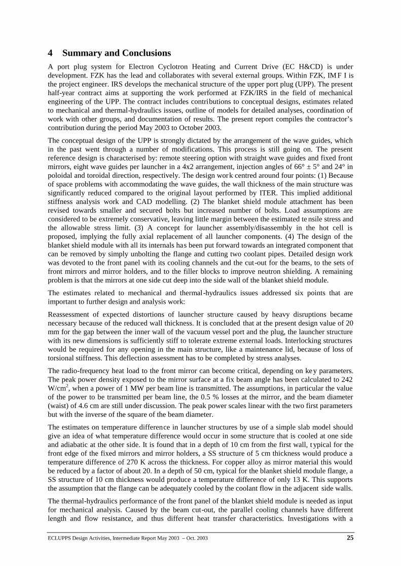
ECLUPPS Design Activities, Intermediate Report May 2003 – Oct. 2003 25
4 Summary and Conclusions A port plug system for Electron Cyclotron Heating and Current Drive (EC H&CD) is under development. FZK has the lead and collaborates with several external groups. Within FZK, IM F I is the project engineer. IRS develops the mechanical structure of the upper port plug (UPP). The present half-year contract aims at supporting the work performed at FZK/IRS in the field of mechanical engineering of the UPP. The contract includes contributions to conceptual designs, estimates related to mechanical and thermal-hydraulics issues, outline of models for detailed analyses, coordination of work with other groups, and documentation of results. The present report compiles the contractor’s contribution during the period May 2003 to October 2003.
The conceptual design of the UPP is strongly dictated by the arrangement of the wave guides, which in the past went through a number of modifications. This process is still going on. The present reference design is characterised by: remote steering option with straight wave guides and fixed front mirrors, eight wave guides per launcher in a 4x2 arrangement, injection angles of 66° ± 5° and 24° in poloidal and toroidal direction, respectively. The design work centred around four points: (1) Because of space problems with accommodating the wave guides, the wall thickness of the main structure was significantly reduced compared to the original layout performed by ITER. This implied additional stiffness analysis work and CAD modelling. (2) The blanket shield module attachment has been revised towards smaller and secured bolts but increased number of bolts. Load assumptions are considered to be extremely conservative, leaving little margin between the estimated te nsile stress and the allowable stress limit. (3) A concept for launcher assembly/disassembly in the hot cell is proposed, implying the fully axial replacement of all launcher components. (4) The design of the blanket shield module with all its internals has been put forward towards an integrated component that can be removed by simply unbolting the flange and cutting two coolant pipes. Detailed design work was devoted to the front panel with its cooling channels and the cut-out for the beams, to the sets of front mirrors and mirror holders, and to the filler blocks to improve neutron shielding. A remaining problem is that the mirrors at one side cut deep into the side wall of the blanket shield module.
The estimates related to mechanical and thermal-hydraulics issues addressed six points that are important to further design and analysis work:
Reassessment of expected distortions of launcher structure caused by heavy disruptions became necessary because of the reduced wall thickness. It is concluded that at the present design value of 20 mm for the gap between the inner wall of the vacuum vessel port and the plug, the launcher structure with its new dimensions is sufficiently stiff to tolerate extreme external loads. Interlocking structures would be required for any opening in the main structure, like a maintenance lid, because of loss of torsional stiffness. This deflection assessment has to be completed by stress analyses.
The radio-frequency heat load to the front mirror can become critical, depending on key parameters. The peak power density exposed to the mirror surface at a fix beam angle has been calculated to 242 W/cm2, when a power of 1 MW per beam line is transmitted. The assumptions, in particular the value of the power to be transmitted per beam line, the 0.5 % losses at the mirror, and the beam diameter (waist) of 4.6 cm are still under discussion. The peak power scales linear with the two first parameters but with the inverse of the square of the beam diameter.
The estimates on temperature difference in launcher structures by use of a simple slab model should give an idea of what temperature difference would occur in some structure that is cooled at one side and adiabatic at the other side. It is found that in a depth of 10 cm from the first wall, t ypical for the front edge of the fixed mirrors and mirror holders, a SS structure of 5 cm thickness would produce a temperature difference of 270 K across the thickness. For copper alloy as mirror material this would be reduced by a factor of about 20. In a depth of 50 cm, typical for the blanket shield module flange, a SS structure of 10 cm thickness would produce a temperature difference of only 13 K. This supports the assumption that the flange can be adequately cooled by the coolant flow in the adjacent side walls.
The thermal-hydraulics performance of the front panel of the blanket shield module is needed as input for mechanical analysis. Caused by the beam cut-out, the parallel cooling channels have different length and flow resistance, and thus different heat transfer characteristics. Investigations with a

26
specialised one-dimensional computer program have proved, that the presented cooling concept of the front panel is feasible with respect to temperature limits, flow distribution and pressure drop. Th e design leaves margin for adjustments, once better data on nuclear heating will be available. Refined thermal-hydraulics and thermo-mechanical analyses are needed when the design has matured.
In a similar way the thermal-hydraulics performance of the double-wall BSM shell has been analysed under the assumption that the coolant flow comes from the front panel and then meanders, guided by ribs, successively through the four side walls. The envisaged cooling concept proved to be viable. Thermal-hydraulic parameters in terms of coolant temperature rise, pressure drop and heat transfer are uncritical. Channel wall temperatures at coolant/structure interfaces are far away from saturation. Expected maximum structure temperatures are also moderate at levels below 200 °C. There is large margin to optimise the pressure drop by reducing the number of fins or by redistributing them.
The aim of the brief study of thermal-hydraulics performance of the front mirrors was to identify critical points and to establish interfaces to other cooling issues of the BSM components. From thermal-hydraulics point of view, the front mirror design and cooling concept look promising. In this concept, the eight mirrors are supplied in parallel with the coolant flow coming from the BSM shell . The coolant temperature rise and pressure drop are small, the flow velocity is still acceptable (here 7.3 m/s). The allowable surface heat flux seems to be given by temperature and thermal stress limits of the Cu-alloy structure. In this estimate with a peak heat flux of 242 W/cm2, the peak structure temperature is still moderate, suggesting that perhaps 400 to 500 W/cm 2 would be feasible. FE analysis is under way.
The contribution to developing extra models for detailed analyses was small. In the field o f neutronics, the design group has provided two CATIA CAD models: one ‘open’ model with minimal shielding inside the BSM and one ‘compact’ model with technically maximum shielding inside the BSM. Detailed mechanical analysis with ANSYS has started only recently with two activities: parametric study of temperature distribution in front mirrors and thermo -mechanical analysis of front panel. Respective models are currently under discussion. Thermal-hydraulics analyses have been performed so far by the author, applying one-dimensional models only.
Briefly summarised are the collaboration with other groups (section 2.4), and the documents prepared during the reporting period under this subject (section 2.5). Next steps are outlined in chapter 3. An important point here is the fact, that besides the reference design dealt with throughout this report, a second design emerged in October 2003.

ECLUPPS Design Activities, Intermediate Report May 2003 – Oct. 2003 27
References [1] U. Fischer et.al.: Analysis of fast neutron streaming in the waveguide channels of the ECRH
system in the ITER upper port, IAEA TM on ECRH Phys. and Tech. for ITER, July 14-16, 2003, Kloster Seeon, Germany.
[2] Efremov Institute: Structural analysis of the upper, equatorial and lower ports, Part 2 of Final Report, JFT_10_00_Subtask 2.
[3] N. Miki, C. Walker: EM load on the diagnostic blanket shield module, ITER document G 55 MD 144 03-03-26 W 0.1.
[4] The SPEAKEASY IV reference manual, Speakeasy computing Corporation, 224 south Michigan ave., Chicago, Illinois 60604 (1993).
[5] B. Eck, Technische Strömungslehre, Springer, 7. Auflage.
[6] Note 310_PortConfig (Oct. 2003).
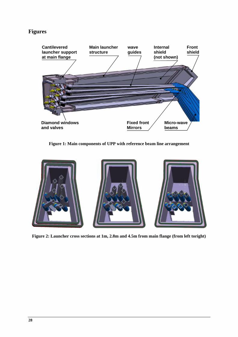
28
Figures
Figure 1: Main components of UPP with reference beam line arrangement
Figure 2: Launcher cross sections at 1m, 2.8m and 4.5m from main flange (from left toright)
Cantileveredlauncher supportat main flange
Main launcherstructure
waveguides
Frontshield
Internalshield(not shown)
Diamond windowsand valves
Fixed frontMirrors
Micro-wavebeams
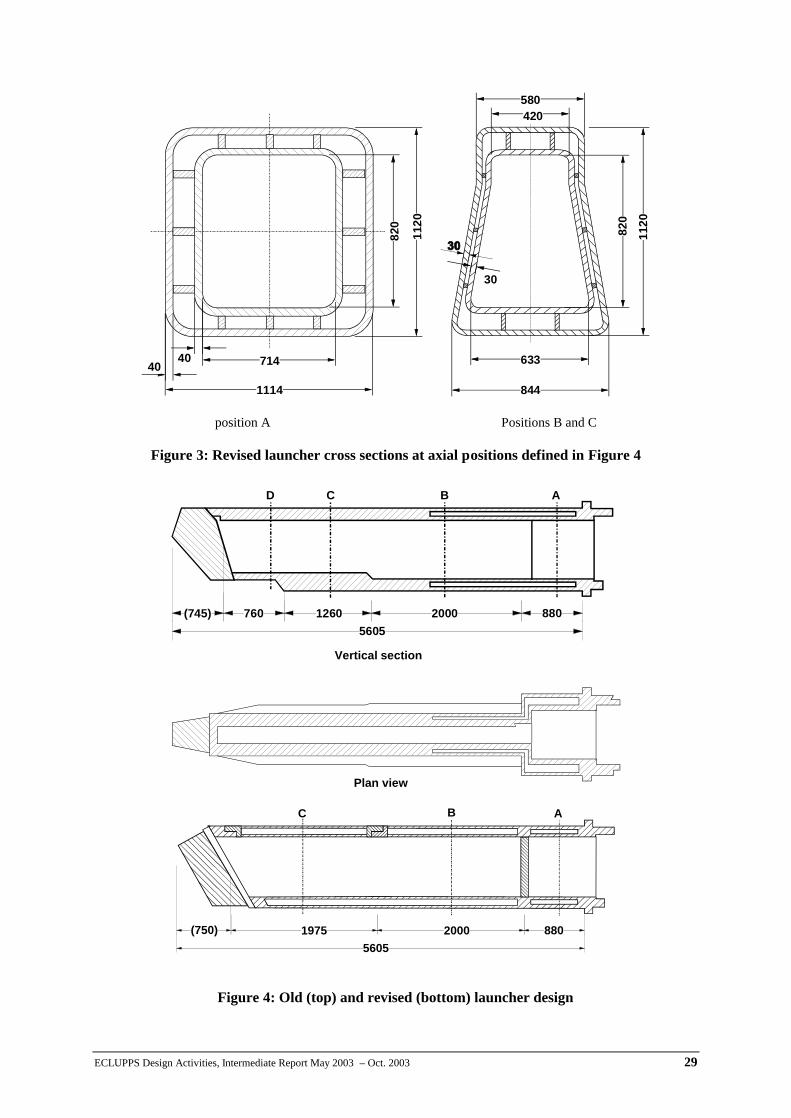
ECLUPPS Design Activities, Intermediate Report May 2003 – Oct. 2003 29
position A Positions B and C
Figure 3: Revised launcher cross sections at axial positions defined in Figure 4
Figure 4: Old (top) and revised (bottom) launcher design
844
1120
820
580420
633
1114
7144040
1120
820
30
88020001975(750)5605
ABC
88020001260760(745)5605
ABCD
Vertical section
Plan view
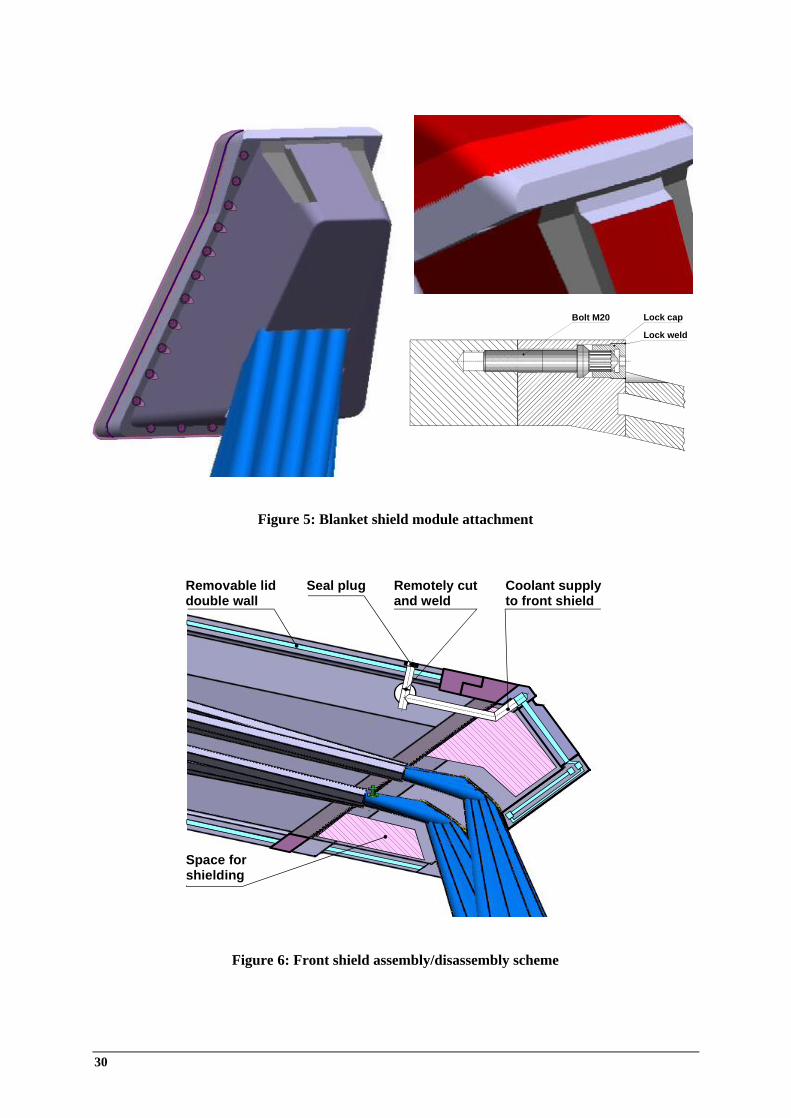
30
Figure 5: Blanket shield module attachment
Figure 6: Front shield assembly/disassembly scheme
Removable liddouble wall
Seal plug Coolant supplyto front shield
Remotely cutand weld
Space forshielding
Bolt M20 Lock cap
Lock weld
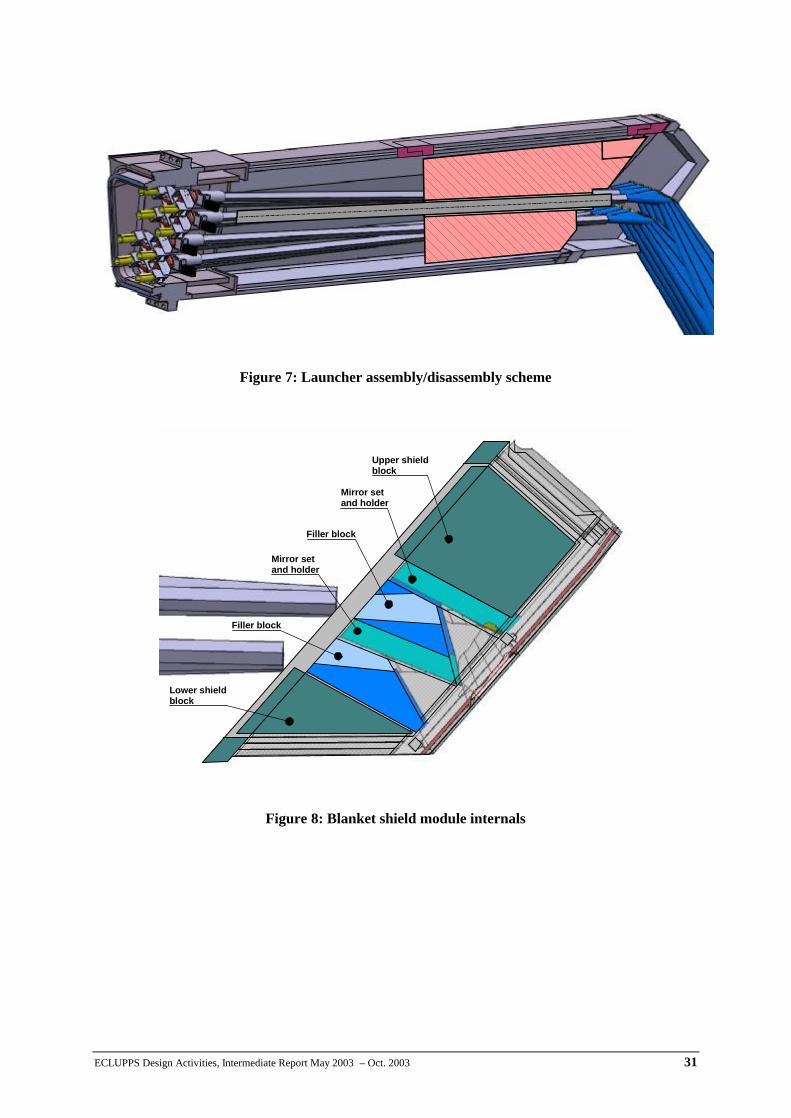
ECLUPPS Design Activities, Intermediate Report May 2003 – Oct. 2003 31
Figure 7: Launcher assembly/disassembly scheme
Figure 8: Blanket shield module internals
Upper shieldblock
Mirror setand holder
Filler block
Mirror setand holder
Filler block
Lower shieldblock
Upper shieldblock
Mirror setand holder
Filler block
Mirror setand holder
Filler block
Lower shieldblock
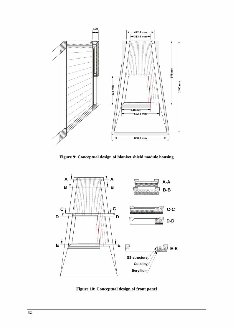
32
Figure 9: Conceptual design of blanket shield module housing
Figure 10: Conceptual design of front panel
313,9 mm
582,4 mm
422,4 mm
808,9 mm
438
mm
975
mm
1400
mm
100
448 mm
AA
B B
C C
D D
E E
A-A
B-B
C-C
D-D
E-E
SS structure
Cu-alloy
Beryllium
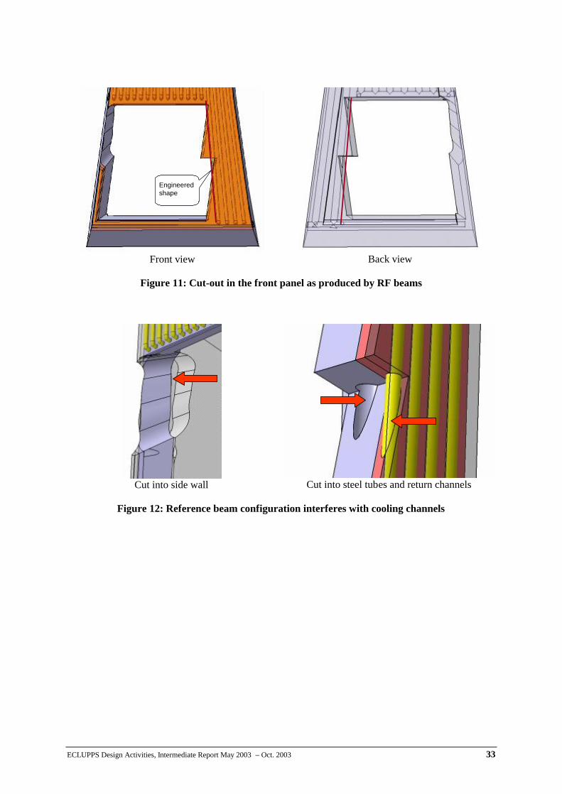
ECLUPPS Design Activities, Intermediate Report May 2003 – Oct. 2003 33
Front view Back view
Figure 11: Cut-out in the front panel as produced by RF beams
Cut into side wall Cut into steel tubes and return channels
Figure 12: Reference beam configuration interferes with cooling channels
Engineeredshape
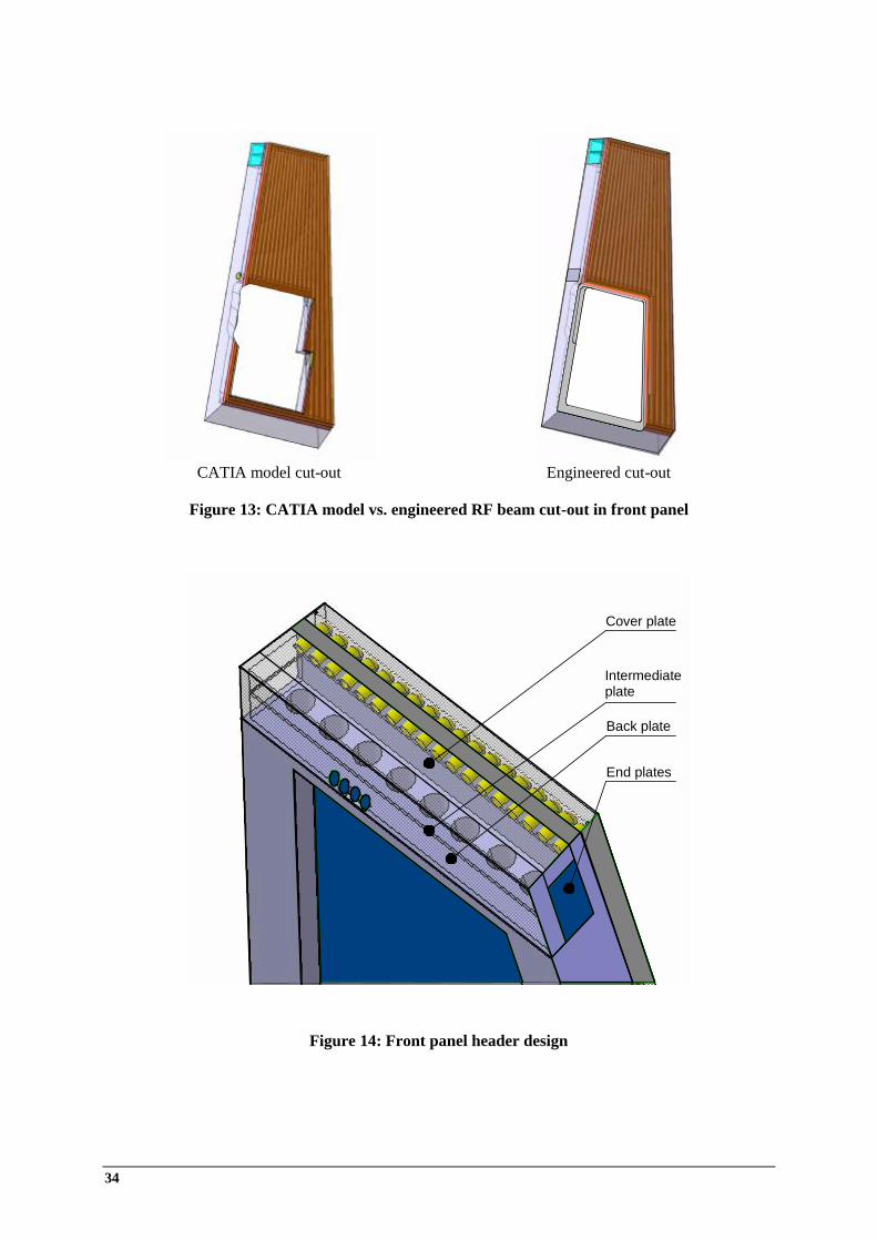
34
Figure 14: Front panel header design
CATIA model cut-out Engineered cut-out
Figure 13: CATIA model vs. engineered RF beam cut-out in front panel
Intermediateplate
Back plate
End plates
Cover plate
Intermediateplate
Back plate
End plates
Cover plate
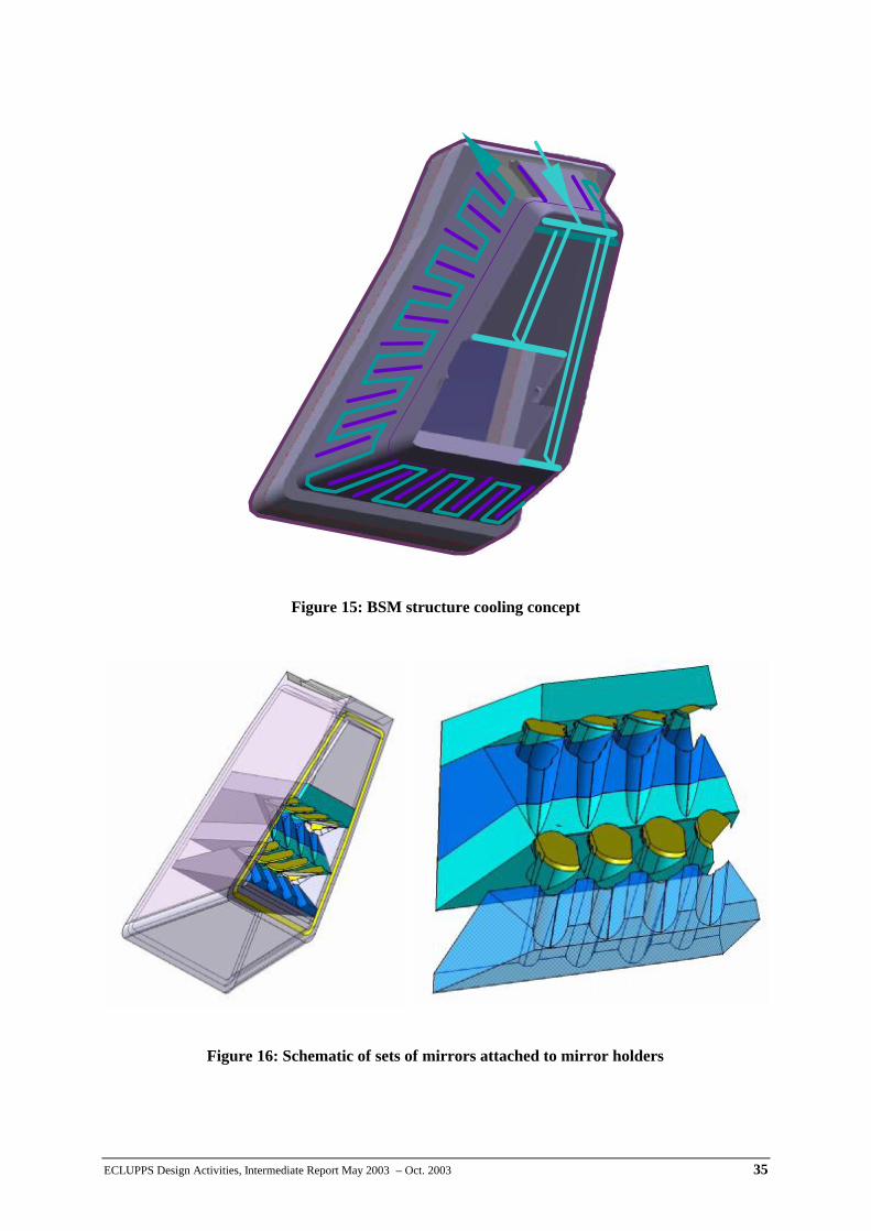
ECLUPPS Design Activities, Intermediate Report May 2003 – Oct. 2003 35
Figure 15: BSM structure cooling concept
Figure 16: Schematic of sets of mirrors attached to mirror holders
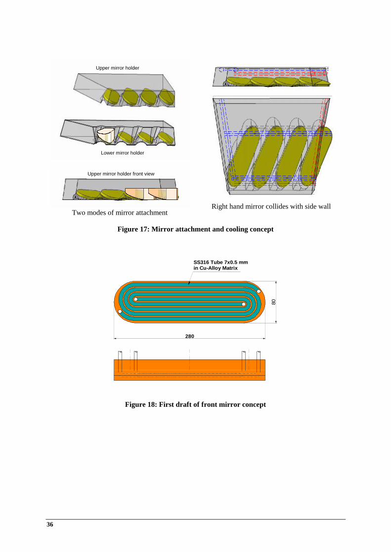
36
Two modes of mirror attachment Right hand mirror collides with side wall
Figure 17: Mirror attachment and cooling concept
Figure 18: First draft of front mirror concept
Upper mirror holder
Lower mirror holder
Upper mirror holder
Lower mirror holder
Upper mirror holder front viewUpper mirror holder front view
SS316 Tube 7x0.5 mmin Cu-Alloy Matrix
280
80
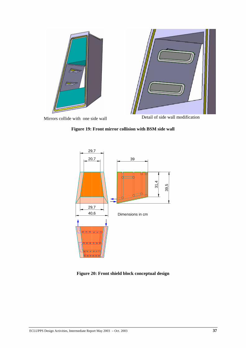
ECLUPPS Design Activities, Intermediate Report May 2003 – Oct. 2003 37
Mirrors collide with one side wall Detail of side wall modification
Figure 19: Front mirror collision with BSM side wall
Figure 20: Front shield block conceptual design
29,740,6
20,7
29,731
,4
39,5
39
Dimensions in cm