Embed Size (px)
DESCRIPTION
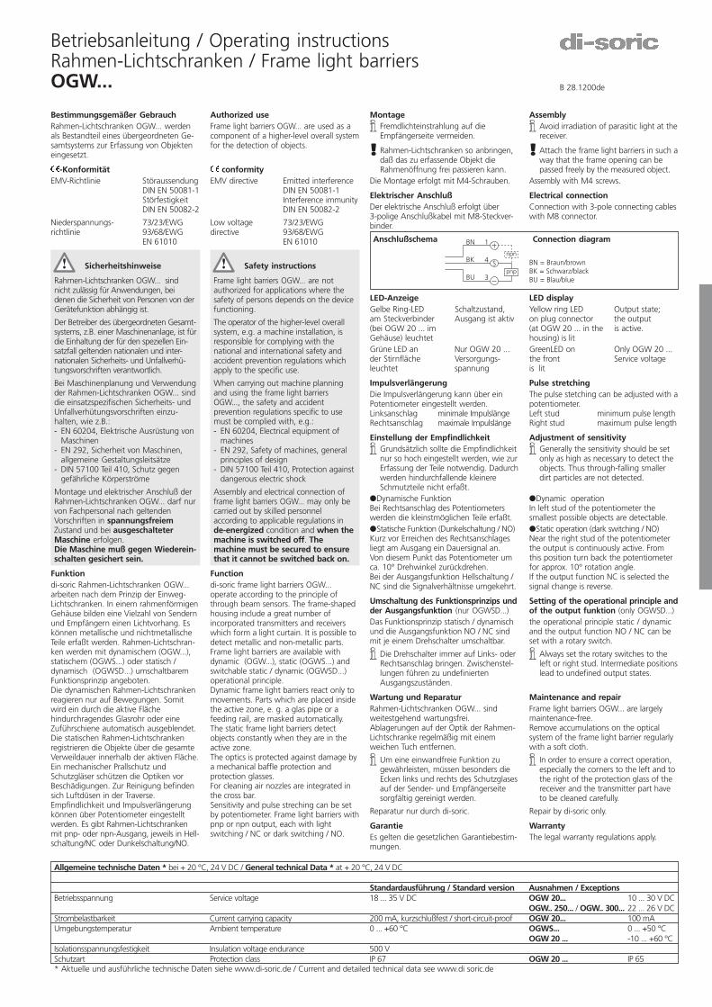
Maintenance and repair Frame light barriers OGW... are largely maintenance-free. Remove accumulations on the optical system of the frame light barrier regularly with a soft cloth. i In order to ensure a correct operation, especially the corners to the left and to the right of the protection glass of the receiver and the transmitter part have to be cleaned carefully. Repair by di-soric only. Warranty The legal warranty regulations apply. B 28.1200de BN BU BK pnp npn 1 4 3 S
Citation preview
Betriebsanleitung / Operating instructionsRahmen-Lichtschranken / Frame light barriersOGW... B 28.1200de
Montagei Fremdlichteinstrahlung auf die
Empfängerseite vermeiden.
! Rahmen-Lichtschranken so anbringen,daß das zu erfassende Objekt dieRahmenöffnung frei passieren kann.
Die Montage erfolgt mit M4-Schrauben.
Elektrischer AnschlußDer elektrische Anschluß erfolgt über3-polige Anschlußkabel mit M8-Steckver-binder.
LED-AnzeigeGelbe Ring-LED Schaltzustand,am Steckverbinder Ausgang ist aktiv(bei OGW 20 ... imGehäuse) leuchtetGrüne LED an Nur OGW 20 ...der Stirnfläche Versorgungs-leuchtet spannung
ImpulsverlängerungDie Impulsverlängerung kann über einPotentiometer eingestellt werden.Linksanschlag minimale ImpulslängeRechtsanschlag maximale Impulslänge
Einstellung der Empfindlichkeiti Grundsätzlich sollte die Empfindlichkeit
nur so hoch eingestellt werden, wie zurErfassung der Teile notwendig. Dadurchwerden hindurchfallende kleinereSchmutzteile nicht erfaßt.
�Dynamische FunktionBei Rechtsanschlag des Potentiometerswerden die kleinstmöglichen Teile erfaßt.�Statische Funktion (Dunkelschaltung / NO)Kurz vor Erreichen des Rechtsanschlagesliegt am Ausgang ein Dauersignal an.Von diesem Punkt das Potentiometer umca. 10° Drehwinkel zurückdrehen.Bei der Ausgangsfunktion Hellschaltung /NC sind die Signalverhältnisse umgekehrt.
Umschaltung des Funktionsprinzips undder Ausgangsfunktion (nur OGWSD...)Das Funktionsprinzip statisch / dynamischund die Ausgangsfunktion NO / NC sindmit je einem Drehschalter umschaltbar.
i Die Drehschalter immer auf Links- oderRechtsanschlag bringen. Zwischenstel-lungen führen zu undefiniertenAusgangszuständen.
Wartung und ReparaturRahmen-Lichtschranken OGW... sindweitestgehend wartungsfrei.Ablagerungen auf der Optik der Rahmen-Lichtschranke regelmäßig mit einemweichen Tuch entfernen.
i Um eine einwandfreie Funktion zugewährleisten, müssen besonders dieEcken links und rechts des Schutzglasesauf der Sender- und Empfängerseitesorgfältig gereinigt werden.
Reparatur nur durch di-soric.
GarantieEs gelten die gesetzlichen Garantiebestim-mungen.
Bestimmungsgemäßer GebrauchRahmen-Lichtschranken OGW... werdenals Bestandteil eines übergeordneten Ge-samtsystems zur Erfassung von Objekteneingesetzt.
-KonformitätEMV-Richtlinie Störaussendung
DIN EN 50081-1StörfestigkeitDIN EN 50082-2
Niederspannungs- 73/23/EWGrichtlinie 93/68/EWG
EN 61010
Sicherheitshinweise
Rahmen-Lichtschranken OGW... sindnicht zulässig für Anwendungen, beidenen die Sicherheit von Personen von derGerätefunktion abhängig ist.
Der Betreiber des übergeordneten Gesamt-systems, z.B. einer Maschinenanlage, ist fürdie Einhaltung der für den speziellen Ein-satzfall geltenden nationalen und inter-nationalen Sicherheits- und Unfallverhü-tungsvorschriften verantwortlich.
Bei Maschinenplanung und Verwendungder Rahmen-Lichtschranken OGW... sinddie einsatzspezifischen Sicherheits- undUnfallverhütungsvorschriften einzu-halten, wie z.B.:- EN 60204, Elektrische Ausrüstung von
Maschinen- EN 292, Sicherheit von Maschinen,
allgemeine Gestaltungsleitsätze- DIN 57100 Teil 410, Schutz gegen
gefährliche Körperströme
Montage und elektrischer Anschluß derRahmen-Lichtschranken OGW... darf nurvon Fachpersonal nach geltendenVorschriften in spannungsfreiemZustand und bei ausgeschalteterMaschine erfolgen.Die Maschine muß gegen Wiederein-schalten gesichert sein.
Funktiondi-soric Rahmen-Lichtschranken OGW...arbeiten nach dem Prinzip der Einweg-Lichtschranken. In einem rahmenförmigenGehäuse bilden eine Vielzahl von Sendernund Empfängern einen Lichtvorhang. Eskönnen metallische und nichtmetallischeTeile erfaßt werden. Rahmen-Lichtschran-ken werden mit dynamischem (OGW...),statischem (OGWS...) oder statisch /dynamisch (OGWSD...) umschaltbaremFunktionsprinzip angeboten.Die dynamischen Rahmen-Lichtschrankenreagieren nur auf Bewegungen. Somitwird ein durch die aktive Flächehindurchragendes Glasrohr oder eineZuführschiene automatisch ausgeblendet.Die statischen Rahmen-Lichtschrankenregistrieren die Objekte über die gesamteVerweildauer innerhalb der aktiven Fläche.Ein mechanischer Prallschutz undSchutzgläser schützen die Optiken vorBeschädigungen. Zur Reinigung befindensich Luftdüsen in der Traverse.Empfindlichkeit und Impulsverlängerungkönnen über Potentiometer eingestelltwerden. Es gibt Rahmen-Lichtschrankenmit pnp- oder npn-Ausgang, jeweils in Hell-schaltung/NC oder Dunkelschaltung/NO.
Anschlußschema Connection diagram
BN = Braun/brownBK = Schwarz/blackBU = Blau/blue
BN
BK
BU
1
4
3
Spnp
npn
Allgemeine technische Daten * bei + 20 °C, 24 V DC / General technical Data * at + 20 °C, 24 V DC
Standardausführung / Standard version Ausnahmen / ExceptionsBetriebsspannung Service voltage 18 ... 35 V DC OGW 20... 10 ... 30 V DC
OGW.. 250... / OGW.. 300... 22 ... 26 V DCStrombelastbarkeit Current carrying capacity 200 mA, kurzschlußfest / short-circuit-proof OGW 20... 100 mAUmgebungstemperatur Ambient temperature 0 ... +60 °C OGWS... 0 ... +50 °C
OGW 20 ... -10 ... +60 °CIsolationsspannungsfestigkeit Insulation voltage endurance 500 VSchutzart Protection class IP 67 OGW 20 ... IP 65* Aktuelle und ausführliche technische Daten siehe www.di-soric.de / Current and detailed technical data see www.di soric.de
Authorized useFrame light barriers OGW... are used as acomponent of a higher-level overall systemfor the detection of objects.
conformityEMV directive Emitted interference
DIN EN 50081-1Interference immunityDIN EN 50082-2
Low voltage 73/23/EWGdirective 93/68/EWG
EN 61010
Safety instructions
Frame light barriers OGW... are notauthorized for applications where thesafety of persons depends on the devicefunctioning.
The operator of the higher-level overallsystem, e.g. a machine installation, isresponsible for complying with thenational and international safety andaccident prevention regulations whichapply to the specific use.
When carrying out machine planningand using the frame light barriersOGW..., the safety and accidentprevention regulations specific to usemust be complied with, e.g.:- EN 60204, Electrical equipment of
machines- EN 292, Safety of machines, general
principles of design- DIN 57100 Teil 410, Protection against
dangerous electric shock
Assembly and electrical connection offrame light barriers OGW... may only becarried out by skilled personnelaccording to applicable regulations inde-energized condition and when themachine is switched off. Themachine must be secured to ensurethat it cannot be switched back on.
Functiondi-soric frame light barriers OGW...operate according to the principle ofthrough beam sensors. The frame-shapedhousing include a great number ofincorporated transmitters and receiverswhich form a light curtain. It is possible todetect metallic and non-metallic parts.Frame light barriers are available withdynamic (OGW...), static (OGWS...) andswitchable static / dynamic (OGWSD...)operational principle.Dynamic frame light barriers react only tomovements. Parts which are placed insidethe active zone, e. g. a glas pipe or afeeding rail, are masked automatically.The static frame light barriers detectobjects constantly when they are in theactive zone.The optics is protected against damage bya mechanical baffle protection andprotection glasses.For cleaning air nozzles are integrated inthe cross bar.Sensitivity and pulse streching can be setby potentiometer. Frame light barriers withpnp or npn output, each with lightswitching / NC or dark switching / NO.
Assemblyi Avoid irradiation of parasitic light at the
receiver.
! Attach the frame light barriers in such away that the frame opening can bepassed freely by the measured object.
Assembly with M4 screws.
Electrical connectionConnection with 3-pole connecting cableswith M8 connector.
LED displayYellow ring LED Output state;on plug connector the output(at OGW 20 ... in the is active.housing) is litGreenLED on Only OGW 20 ...the front Service voltageis lit
Pulse stretchingThe pulse stetching can be adjusted with apotentiometer.Left stud minimum pulse lengthRight stud maximum pulse length
Adjustment of sensitivityi Generally the sensitivity should be set
only as high as necessary to detect theobjects. Thus through-falling smallerdirt particles are not detected.
�Dynamic operationIn left stud of the potentiometer thesmallest possible objects are detectable.�Static operation (dark switching / NO)Near the right stud of the potentiometerthe output is continuously active. Fromthis position turn back the potentiometerfor approx. 10° rotation angle.If the output function NC is selected thesignal change is reverse.
Setting of the operational principle andof the output funktion (only OGWSD...)the operational principle static / dynamicand the output function NO / NC can beset with a rotary switch.
i Always set the rotary switches to theleft or right stud. Intermediate positionslead to undefined output states.
Maintenance and repairFrame light barriers OGW... are largelymaintenance-free.Remove accumulations on the opticalsystem of the frame light barrier regularlywith a soft cloth.
i In order to ensure a correct operation,especially the corners to the left and tothe right of the protection glass of thereceiver and the transmitter part haveto be cleaned carefully.
Repair by di-soric only.
WarrantyThe legal warranty regulations apply.
di-soricIndustrie-electronic GmbH & Co.Steinbeisstraße 6D 73660 UrbachTel. ++49 (0) 71 81 / 98 79-0Fax ++49 (0) 71 81 / 98 79-21e-mail [email protected] www.di-soric.de
Alle technischen Angaben beziehen sich auf denStand 12/00, Änderungen bleiben vorbehalten.Da Irrtümer und Druckfehler nicht auszuschließensind, gilt für alle Angaben „ohne Gewähr“.
All technical specifications refer to the state ofthe art 12/00, they are subject to modifications.As typographical and other errors cannot be excluded,all data are given „without engagement“.
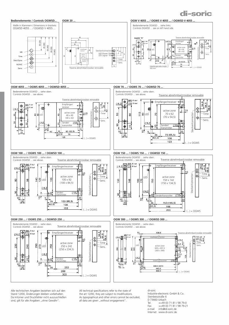
OGW 20 ... OGW V 4055 ... / OGWS V 4055 ... / OGWSD V 4055 ...
OGW 4055 ... / OGWS 4055 ... / OGWSD 4055 ... OGW 70 ... / OGWS 70 ... / OGWSD 70 ...
OGW 100 ... / OGWS 100 ... / OGWSD 100 ... OGW 150 ... / OGWS 150 ... / OGWSD 150 ...
OGW 250 ... / OGWS 250 ... / OGWSD 250 ... OGW 300 ... / OGWS 300 ... / OGWSD 300 ...
Traverse abnehmbar/crossbar removable
Sender/transm.
Time
Sens.
Stecker/connector
activezone
20 x 20
Empfänger/receiver
LED Signal YELED Power GN
Empfänger/receiver
Sender/transmitter
Traverse abnehmbar/crossbar removable
active zone40 x 49
(40 x 42)
Time
Sens.
Stec
ker/
conn
ecto
r
(...) = OGWSKabellänge/cable length300 mm
LED
Time
Sens.
Stec
ker/
conn
ecto
r
Empfänger/receiver
Sender/transmitter
Traverse abnehmbar/crossbar removable
active zone40 x 49(40 x 42)
LED
(...) = OGWS
Time
Sens.
Stec
ker/
conn
ecto
r
Empfänger/receiver
Sender/transmitter
Traverse abnehmbar/crossbar removable
active zone70 x 62
(70 x 54,5)LED
(...) = OGWS
Time
Sens.
Stec
ker/
conn
ecto
r
Empfänger/receiver
Sender/transmitter
Traverse abnehmbar/crossbar removable
active zone100 x 92
(100 x 84,5)LED
(...) = OGWS
Time
Sens.
Stec
ker/
conn
ecto
r
Empfänger/receiver
Sender/transmitter
Traverse abnehmbar/crossbar removable
active zone150 x 142
(150 x 134,5)
LED
(...) = OGWS
Time
Sens.
Stec
ker/
conn
ecto
r
Empfänger/receiver
Sender/transmitter
Traverse abnehmbar/crossbar removable
active zone250 x 242
(250 x 234,5)LED
(...) = OGWS
Time
Sens.
Stec
ker/
conn
ecto
r
Empfänger/ receiver
Sender/ transmitter
Traverse abnehmbar/crossbar removable
active zone300 x 397,5(300 x 390)
LED
(...) = OGWS
Bedienelemente / Controls OGWSD...
NO/NC
Stat./Dyna.
Time
Sens.
M875
(60
)
65 (
50)
55 (
40)
45 (
30)
35 (
20)
Bedienelemente OGWSD ... siehe links.Controls OGWSD ... see on left hand side.
Bedienelemente OGWSD ... siehe oben.Controls OGWSD ... see above.
Bedienelemente OGWSD ... siehe oben.Controls OGWSD ... see above.
Bedienelemente OGWSD ... siehe oben.Controls OGWSD ... see above.
Bedienelemente OGWSD ... siehe oben.Controls OGWSD ... see above.
Bedienelemente OGWSD ... siehe oben.Controls OGWSD ... see above.
Bedienelemente OGWSD ... siehe oben.Controls OGWSD ... see above.
Maße in Klammern / Dimensions in brackets:OGWSD 4055 ... / OGWSD V 4055 ...