Embed Size (px)
Citation preview

K+H Vertriebs- und Entwicklungsgesellschaft mbH Auf dem Kessellande 4a • 30900 Wedemark/Germany
Tel: +49 (0) 5130 5848-0Fax: +49 (0) 5130 5848-11Email: infoklein-hummel.de
www.klein-hummel.dewww.klein-hummel.com
Digital Studio Monitor
Installation and Operation Manual
O 500 C
058-E0012Version 021025
Page 2
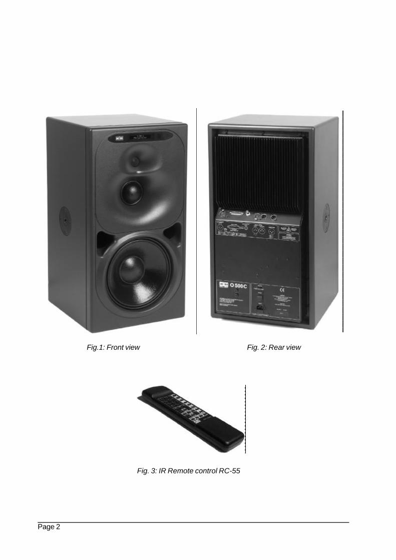
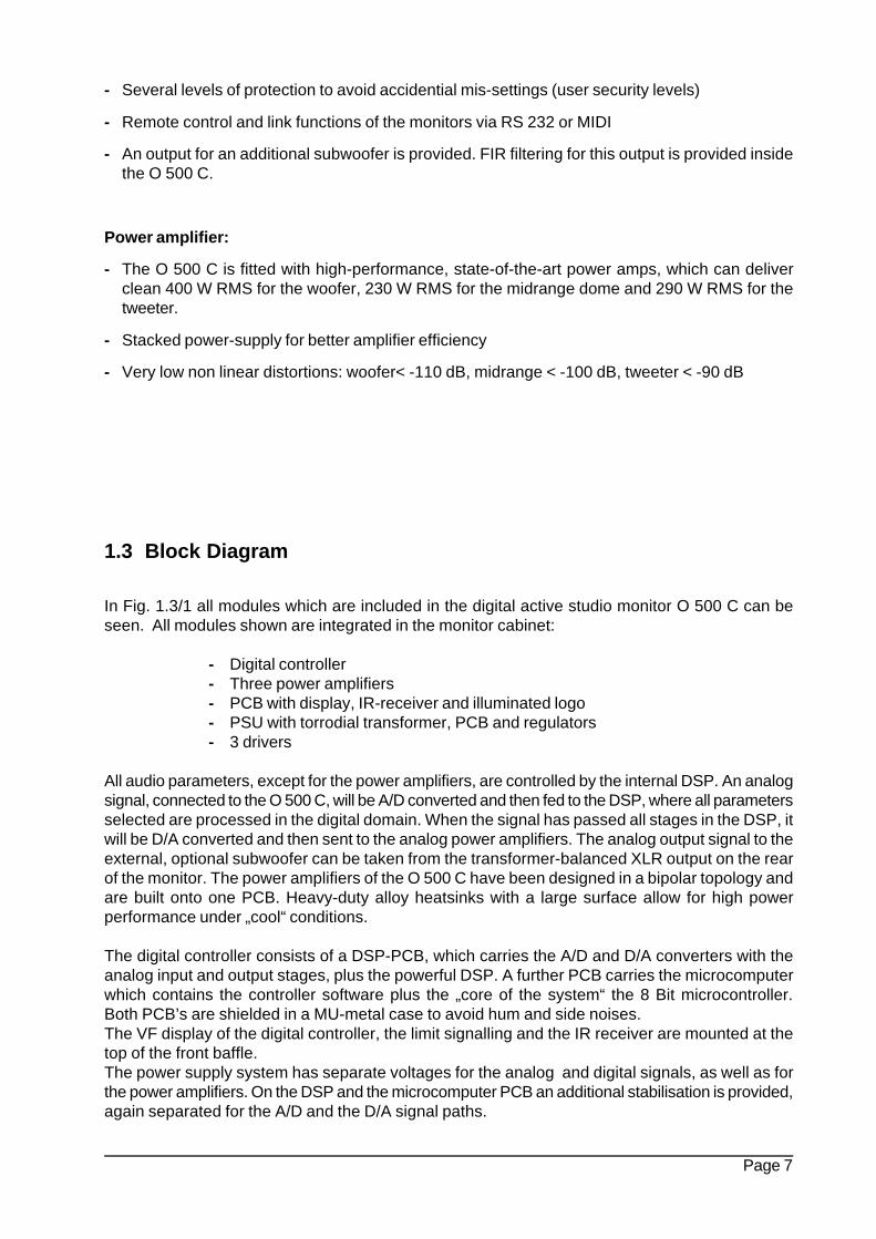
Fig.1: Front view Fig. 2: Rear view
Fig. 3: IR Remote control RC-55
Page 3
Contents:
0 Safety instructions...................................................................................................................4
1 Description
1.1 Advantages of digitally controlled monitor systems...............................................................51.2 System concept......................................................................................................................61.3 Block diagram.........................................................................................................................71.4 The modules of the digital controller.......................................................................................9
.2 Installation / Setup
2.1 Positioning / Mounting .........................................................................................................122.2 Connectors and wiring .........................................................................................................142.3 VF-display on the front baffle...............................................................................................182.4 Recall of the loudspeaker parameter setup.........................................................................18
3 Operation / Description of Menus
3.1 Menu structure and concept of operation............................................................................193.2 Main Menu............................................................................................................................213.3 System Menu........................................................................................................................233.4 EQ Menu...............................................................................................................................24
4 Remote Control
4.1 Infrared remote control.........................................................................................................264.2 Control via RS-232 or MIDI..................................................................................................27
5 Room EQ setup
5.1 Room EQ..............................................................................................................................305.2 Parametric EQ (PEQ)...........................................................................................................32
.6 Calculation of parameters....................................................................................................35
7 Technical data.............................................................................................................36
Page 4
0 Safety Instructions
It is absolutely essential that you read these safety instructions carefully before connecting andusing this K+H product. Your safety depends on it. Furthermore, failure to follow these instructionsvoids the warranty. To ensure safe operation for years to come, keep these instructions in a safe place forfuture reference. K+H has manufactured this product in accordance with IEC 1992 (SEC) 39 standards, thentested and delivered it in safe operating condition. To maintain it in this condition, you must:
• observe all safety instructions,• use the product only as described herein,• have any maintenance, repairs, or modifications performed only by K+H or other authorized personnel,
and• ensure that the room in which you use this product is wired in accordance with the local electrical code.
Warning!• When the interior of the cabinet is exposed, touching some parts can lead to an electric shock.• If you need to gain access to the interior electronics of the unit, always disconnect the unit from any and
all power sources first.• Any repairs, maintenance, or other service of the unit when its interior compartment is
exposed may only be performed safely (in accordance with VBG 4) by authorizedtechnicians familiar with all the risks involved. Even in an unplugged state, a fully chargedcapacitor in the unit can zap the unsuspecting.
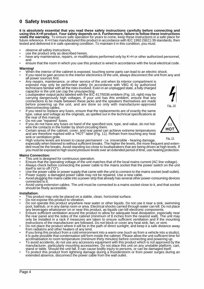
• Loudspeaker output jacks labeled with the IEC 417/5036 emblem (Fig. 10, right) may becarrying dangerously high voltages. If your unit has this emblem, ensure that anyconnections to be made between these jacks and the speakers themselves are madebefore powering up the unit, and are done so only with manufacturer-approvedinterconnecting cables.
• If you need to replace any fuses, ensure that the replacements are of exactly the sametype, value and voltage as the originals, as spelled out in the technical specifications atthe rear of this manual.
• Do not use "repaired" fuses.• If you do not have any fuses on hand of the specified size, type, and value, do not hot-
wire the contacts in the holder by short-circuiting them.• Certain areas of the cabinet, cover, and rear panel can achieve extreme temperatures
and are therefore marked with a "HOT" label (Fig. 11). Refrain from touching any heatsink or ventilation grille.
• High volume levels are known to cause permanent - i.e. irreversible - hearing damage,especially when listened to without sufficient breaks. The higher the levels, the more frequent and exten-ded must be the breaks. Avoid standing too close to loudspeakers that are being driven at high levels. Ifyou must be exposed to high sound pressure levels over an extended period of time, use hearing protection.
Mains Connection:• This unit is designed for continuous operation.• Ensure that the operating voltage of the unit matches that of the local mains current (AC line voltage).• Always check before connecting the power cable to the mains socket that the power switch on the unit
itself is set to off ("O").• Use the power cable or power supply that came with the unit to connect to the mains socket (wall outlet).• Power supply: a damaged power cable may not be repaired. Use a new cable.• Avoid plugging the mains cable into a power strip that already has several other power-consuming devices
connected to it.• Avoid using extension cables. The unit must be connected to a mains socket close to it, and that socket
should be freely accessible.
Installation:• This product may only be placed on a stable, clean, horizontal surface.• Do not expose this product to vibration.• Do not operate this product anywhere near water or other liquids. Do not use it near a sink, swimming
pool, bathtub, or in any damp room or area. Electrical shocks carried through water can kill. Do not placeany beverages whatsoever on or near this product, as liquids can kill electronic components.
• Ensure sufficient ventilation around the product to allow for adequate heat dissipation, especially nearthe rear panel and the sides of the cabinet (minimum of 8 inches from the nearest wall). The unit mayonly be installed in a rack if measures are taken to ensure sufficient ventilation and if the mountinginstructions of the manufacturer are followed. Do not block or cover any heat sink, fan, or vent.
• Do not place the product where it will be in the path of direct sunlight, and keep it a safe distance awayfrom radiators and other heaters of any kind.
• If you bring this product from a cold environment into a warm one (such as from a vehicle into a studio),it is quite possible that condensation will form inside the cabinet. Please allow the unit sufficient time foracclimatisation to room temperature (minimum thirty minutes) before connecting and powering up.
• To avoid accidents, do not use any accessory equipment with this product which is not approved by themanufacturer, particularly mounting accessories. Do not place this unit on any unstable platform, cart,stand or table. Should the unit fall, it can cause bodily injury to persons, or can be damaged itself.
• To protect this product from lightning damage during a thunderstorm or from power surges during anextended absence, disconnect the power cable from the wall outlet.
Fig. 10
Fig. 11
Page 5
1.1 Advantages of Digitally Controlled Monitor Systems
- optimizing of frequency responses, e.g. an absolutely linear adjustment from 30 Hz – 20 kHz.Any other desired frequency curves can be set/adjusted/stored
- setting of phase response(s) in any combination, such as linear-phase, minimum-phase, mixed-phase with the resulting group-delays (constant group delay, continiously decreasing, etc.)
- attack and release times of speakers will be remarkably improved
- more precise stereo-locating, as there is virtually no deviation in a stereo pair
- programmed EQ settings can be recalled instantly for special needs and functions
- a nearly unlimited number of EQ-settings can be stored and switched easily, e.g. for differentlistening locations in the same room, second control-room, different operating modes (mixing /demonstration) etc.
- the delay-times of the speakers can be adjusted and stored for different listening distances
- the monitor can be delayed for optimized sync with analog/digital film/video, as a delay-line inhigh-quality multi-speaker setups, concerts, multi-media or surround setups
- the slope at the crossover frequencies can be adjusted up to 96 dB per octave, which can besaid is close to ideal (but never possible with analog designs). In this case the overlappingfrequencies reproduced from both drivers in the x-over area is only a few Hz wide, which has thefollowing advantages:
1. every driver can be used in it’s perfect frequency-response range2. in the area of the crossover frequency we can avoid phase-cancellations to a large extent3. it is possible to select a perfect horn for every driver with it’s own directivity (individual depth of the horns can be adjusted by the system).ð The directivity can be designed to be almost perfect for the horizontal and vertical level!
- problems caused by resonances and reflections in control rooms can be minimized andcompensated to a high degree by adjusting the response of the speaker-system in the room.This will be made in a separate EQ and measuring session in the control-room
- for protection of the drivers fast and efficient limiters are provided which take care of the short-term max-level and the peak-power capacity of the driver, so in case of a possible overload thelimiters will redurce the levels (feed forward limiter) without producing any distortions, as it is thecase in analog limiters.
- Digital and analog audio input connectors
- Infrared remote-control for all parameters (can be selected individually without any PC)
Page 6
1.2 System Concept
- Active 3-way studio monitor with integrated digital controller and high performance amplifierswith power amplifiers of 400 W RMS for the woofer, 230 W RMS for midrange driver and 290 WRMS for the tweeter
Concept of Speakers and Cabinet:
- 12“ woofer with alloy-chassis, forced air cooling voicecoil, high efficiency and long, linear excursion
- 3“ voicecoil midrange dome in sealed enclosure, with strong magnet and lowest distortion
- 1“ titanium dome tweeter with high efficiency and ultra-low distortion
- Cabinet made of strong, resonance free HDF material. It is fitted with a moulded front-baffle withintegrated horns and ducted ports for compression-free low frequency response, and optimizedhorns for midrange/tweeter, offering perfect dispersion for all three speakers by minimizinginterferences and reflections
- Cabinet comes with multiple fittings for an individual choice of mounting adaptors
Digital Controller:
- The integrated digital controller includes the electronic crossover, the EQ for every driver-system,a delay of several milliseconds per chassis, all limiter functions, a master delay, flexible adjustmentsfor local EQ and a fully parametric 10-band EQ
- Independent adjustments for amplitude and phase are provided for every chassis and for thecomplete system by the use of digital FIR filter technology (FIR = Finite Impulse Response)
- Unlike other internal or external digital controllers, the controller of the O 500 C is programmedwith individual filter settings for every driver system which were measured in an anechoic chamberand set at the factory. All tolerances of the individual drivers, the power amps and the controlleritself are recorded and will be taken into the calculation for the setup / equalizing of everyspecific O 500 C monitor system
- Adjustment for positioning in the control room or studio can be made by the fully parametric EQwith IIR filters directly in the monitor
- Individual FIR filter settings can be made by aligning the O 500 C in it’s final position in the studio(optional). This way the room specific modes, such as resonances, standing waves etc. can becompensated
- A precise limiter section will allow for perfect system management by offering a “ look aheadsignal analysis“ of the clipping mode of all power amps, the max. excursion of the drivers andthe long term temperature management and it’s peak allowances
- The important stages in the signal path of the digital controller are calculated accurately with 48Bit performance
- Stacked A/D converters (gain ranging) in Delta/Sigma technology offer a wide dynamic range onthe input side, by resulting in ultra-low distortion figures at the same time
- High performance quality D/A converters in Delta/Sigma technology in all input/output stages
- High quality concept for the PSU and fully capsuled controller electronics
- Variety of analog and digital audio connections
- Ergonomic and easy operation via infrared remote-control (no PC needed)
Page 7
- Several levels of protection to avoid accidential mis-settings (user security levels)
- Remote control and link functions of the monitors via RS 232 or MIDI
- An output for an additional subwoofer is provided. FIR filtering for this output is provided insidethe O 500 C.
Power amplifier:
- The O 500 C is fitted with high-performance, state-of-the-art power amps, which can deliverclean 400 W RMS for the woofer, 230 W RMS for the midrange dome and 290 W RMS for thetweeter.
- Stacked power-supply for better amplifier efficiency
- Very low non linear distortions: woofer< -110 dB, midrange < -100 dB, tweeter < -90 dB
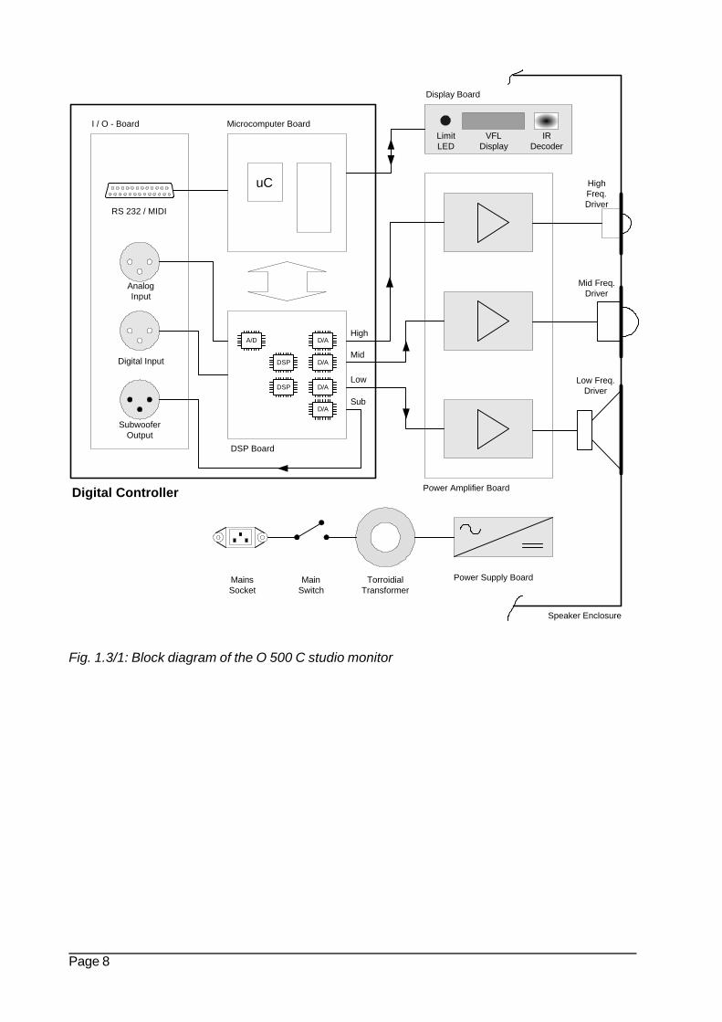
1.3 Block Diagram
In Fig. 1.3/1 all modules which are included in the digital active studio monitor O 500 C can beseen. All modules shown are integrated in the monitor cabinet:
- Digital controller- Three power amplifiers- PCB with display, IR-receiver and illuminated logo- PSU with torrodial transformer, PCB and regulators- 3 drivers
All audio parameters, except for the power amplifiers, are controlled by the internal DSP. An analogsignal, connected to the O 500 C, will be A/D converted and then fed to the DSP, where all parametersselected are processed in the digital domain. When the signal has passed all stages in the DSP, itwill be D/A converted and then sent to the analog power amplifiers. The analog output signal to theexternal, optional subwoofer can be taken from the transformer-balanced XLR output on the rearof the monitor. The power amplifiers of the O 500 C have been designed in a bipolar topology andare built onto one PCB. Heavy-duty alloy heatsinks with a large surface allow for high powerperformance under „cool“ conditions.
The digital controller consists of a DSP-PCB, which carries the A/D and D/A converters with theanalog input and output stages, plus the powerful DSP. A further PCB carries the microcomputerwhich contains the controller software plus the „core of the system“ the 8 Bit microcontroller.Both PCB’s are shielded in a MU-metal case to avoid hum and side noises.The VF display of the digital controller, the limit signalling and the IR receiver are mounted at thetop of the front baffle.The power supply system has separate voltages for the analog and digital signals, as well as forthe power amplifiers. On the DSP and the microcomputer PCB an additional stabilisation is provided,again separated for the A/D and the D/A signal paths.
Page 8
Fig. 1.3/1: Block diagram of the O 500 C studio monitor
uC
VFLDisplay
DSP Board
Power Supply BoardTorroidialTransformer
MainsSocket
Microcomputer Board
Power Amplifier Board
IRDecoder
RS 232 / MIDI
HighFreq.Driver
Mid Freq.Driver
Low Freq.Driver
Display Board
LimitLED
Speaker Enclosure
DSP
DSP
MainSwitch
I / O - Board
Digital Input
AnalogInput
A/D
D/A
SubwooferOutput
Digital Controller
High
Mid
Low
Sub
D/A
D/A
D/A
Page 9
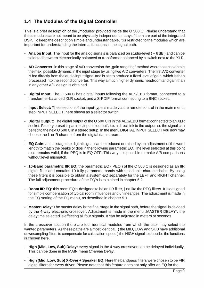
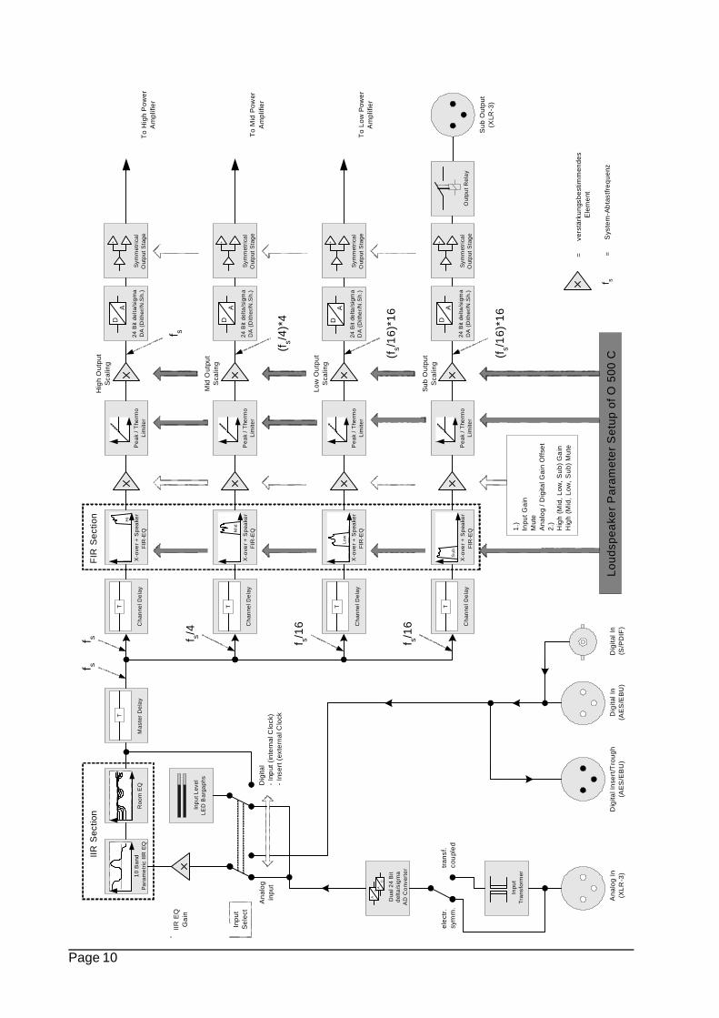
1.4 The Modules of the Digital Controller
This is a brief description of the „modules“ provided inside the O 500 C. Please understand thatthese modules are not meant to be physically independent, many of them are part of the integratedDSP. To keep the description simple and understandable, it is restricted to the modules which areimportant for understanding the internal functions in the signal path.
- Analog Input: The input for the analog signals is balanced on studio-level ( + 6 dB ) and can beselected between electronically balanced or transformer balanced by a switch next to the XLR.
- AD Converter: in this stage of A/D conversion the „gain rangeing“ method was chosen to obtainthe max. possible dynamic in the input stage by using two A/D converters. The first A/D converteris fed directly from the audio input signal and is set to produce a fixed level of gain, which is thenprocessed into the second converter. This way a much higher dynamic headroom and gain thanin any other A/D design is obtained.
- Digital Input: The O 500 C has digital inputs following the AES/EBU format, connected to atransformer-balanced XLR socket, and a S-PDIF format connecting to a BNC socket.
- Input Select: The selection of the input-type is made via the remote control in the main menu,step INPUT SELECT, here shown as a selector switch.
- Digital Output: The digital output of the O 500 C is in the AES/EBU format connected to an XLRsocket. Factory preset is parallel „input to output“, i.e. a direct link to the output, so the signal canbe fed to the next O 500 C in a stereo setup. In the menu DIGITAL INPUT SELECT you now maychoose the L or R channel from the digital data stream.
.- EQ Gain: at this stage the digital signal can be reduced or raised by an adjustment of the word
length to match the peaks or dips in the following parametric EQ. The level selected at this pointalso remains valid, if the PEQ is in EQ OFF. This way it is possible to make A/B comparisonswithout level mismatch.
- 10-Band parametric IIR EQ: the parametric EQ ( PEQ ) of the O 500 C is designed as an IIRdigital filter and contains 10 fully parametric bands with selectable characteristics. By usingthese filters it is possible to obtain a system-EQ separately for the LEFT and RIGHT channel.The full adjustment procedure of the EQ’s is explained in chapter 5.2
- Room IIR EQ: this room EQ is designed to be an IIR filter, just like the PEQ filters. It is designedfor simple compensation of typical room influences and unlinearities. The adjustment is made inthe EQ setting of the EQ menu, as described in chapter 5.1.
- Master Delay: The master delay is the final stage in the signal path, before the signal is devidedby the 4-way electronic crossover. Adjustment is made in the menu „MASTER DELAY“, thedelaytime selected is effecting all four signals. It can be adjusted in meters or seconds.
In the crossover section there are four identical modules from which the user may select thewanted parameters. As these paths are almost identical, ( the MID, LOW and SUB have additionaldownsampling filters to compensate for calculation-speed ) the HIGH signal to describe the functionsis chosen here.
- High (Mid, Low, Sub) Delay: every signal in the 4-way crossover can be delayed individually.This can be done in the MAIN menu Channel Delay.
- High (Mid, Low, Sub) X-Over + Speaker EQ: Here the bandpass filters were chosen to be FIRdigital filters for every driver. Please note that this feature does not only offer an EQ for the
Page 10
Inpu
tT
rans
form
er
Dig
ital I
n(S
/PD
IF)
Dig
ital I
n(A
ES
/EB
U)
Dig
ital I
nser
t/Tro
ugh
(AE
S/E
BU
)A
nalo
g In
(XLR
-3)
Sub
Out
put
(XLR
-3)
AD
AD
Dua
l 24
Bit
del
ta/s
igm
aA
D C
onv
erte
r
Inp
ut L
evel
LE
D B
arga
phs
tran
sf.
cou
pled
elec
tr.
sym
m.
Dig
ital
- In
put
(in
tern
al C
lock
)-
Inse
rt (
exte
rnal
Clo
ck
Ana
log
inpu
t
1.)
Inpu
t Gai
nM
ute
Ana
log
/ Dig
ital G
ain
Offs
et2.
)H
igh
(Mid
, Low
, Sub
) G
ain
Hig
h (M
id, L
ow, S
ub)
Mut
e
=
ver
stär
kung
sbes
timm
ende
sE
lem
ent
IIR E
QG
ain
Inpu
tS
elec
t
+ -
Sym
met
rica
lO
utp
ut S
tag
e1
0 B
and
Pa
ram
etr
ic I
IR E
Q
+ -
Sym
met
rica
lO
utp
ut S
tag
e
+ -
Sym
met
rica
lO
utp
ut S
tag
e
+ -
Sym
met
rica
lO
utp
ut S
tag
eP
eak
/ T
herm
oL
imite
r
Pe
ak /
The
rmo
Lim
iter
Pe
ak /
The
rmo
Lim
iter
Pe
ak /
The
rmo
Lim
iter
X-o
ver
+ S
pea
ker
FIR
-EQ
Hi
X-o
ver
+ S
pea
ker
FIR
-EQ
Low
X-o
ver
+ S
pea
ker
FIR
-EQ
Sub
Ch
anne
l De
lay
T
Ch
anne
l De
lay
T
Ch
anne
l De
lay
T
Ch
anne
l De
lay
T
Mas
ter
De
lay
T
X-o
ver
+ S
pea
ker
FIR
-EQM
id
Roo
m E
Q
IIR S
ectio
nF
IR S
ectio
n
Loud
spea
ker
Par
amet
er S
etup
of O
500
C
Hig
h O
utpu
tS
calin
g
Mid
Out
put
Sca
ling
Low
Out
put
Sca
ling
Sub
Out
put
Sca
ling
fs
f s/4
f s/16
f s/16
fs
(f
s/1
6)*1
6
(f
s/1
6)*1
6
(f
s/4)
*4
f s
f s=
S
yste
m-A
bta
stfr
eque
nz
AD
24 B
it de
lta/s
igm
aD
A (
Dith
er/
N.S
h.)
AD
24 B
it de
lta/s
igm
aD
A (
Dith
er/
N.S
h.)
AD
24 B
it de
lta/s
igm
aD
A (
Dith
er/
N.S
h.)
AD
24 B
it de
lta/s
igm
aD
A (
Dith
er/
N.S
h.)
To
Low
Pow
erA
mpl
ifier
To
Hig
h P
ower
Am
plifi
er
To
Mid
Pow
erA
mpl
ifier
Out
put
Rel
ay
Page 11
frequency response, but also for a very complex adjustment of the system, including the phaseadjustments! Furthermore the reaction of the drivers and the electric performance of the amplifierand the digital controller itself are monitored by the controller.
- Gain: This function adjusts the individual gain in every signal path of the crossover. The valuesof possible parameters are influenced by a multitude of menu settings, which can be selectedindividually.
- All adjustments (values set) in the menus INPUT GAIN, MUTE ans ANALOG/DIGITALGain Offset will become effective in every signal path of the crossover.
- In the menus HIGH/MID/LOW/SUB GAIN and HIGH/MID/LOW/SUB MUTE it is possible toselect the individual signal path in the crossover, where the parameter adjustments or changingthe gain should become active.
- Peak / RMS / Thermo limiter: The following limiter section contains a PEAK/RMS limiter and athermo limiter. They have been designed to avoid the clipping of the power amps, a too highpeak power to the drivers and a limitation of the max. excursion of the voice coils and cones. Thethermo limiter has been added to avoid a thermal overload of the voice coils.
All these parameters are set at the factory and cannot be adjusted by the user. Only the releasetime of the peak limiter can be varied by him.
- High (Mid, Low, Sub) Output Scaling: This part of the controller takes a strong influence on thesignal level, finally driving the D/A converter. This function is recalled and reset with every LOADmemory.
- Balanced Output Stage: The analog output driver of the digital controller of a fully balanceddesign. In combination with the balanced input stages a very low influence of noises to theaudiosignal is achieved.
- Analog Subwoofer Output Stage: This analog output from the digital controller is on a balancedXLR socket for direct connection of an optional active subwoofer.
Page 12
2.1 Positioning / Mounting
The studio monitor O 500 C has been designedas a Main / Midfield-Monitor, and may be usedas a main monitor in smaller or midsize controlrooms / studios.The minimum distance to the listening positionshould be at least 2,5 meters.
Ways of mounting:- on a stand with mounting bracket LH35
- on all surfaces with the tilting adaptor LH 36,in a combination with the TV spigot LH 29, orthe tripod stand adaptor LH 28.
- from the ceiling with mounting bracket LH 35
- free standing on a stand or pedestal
- flush-mount into a wall
- For more detailed information on the manypossibilities and adaptors, please see ourstudio catalogue SO1, pages 42 and 43
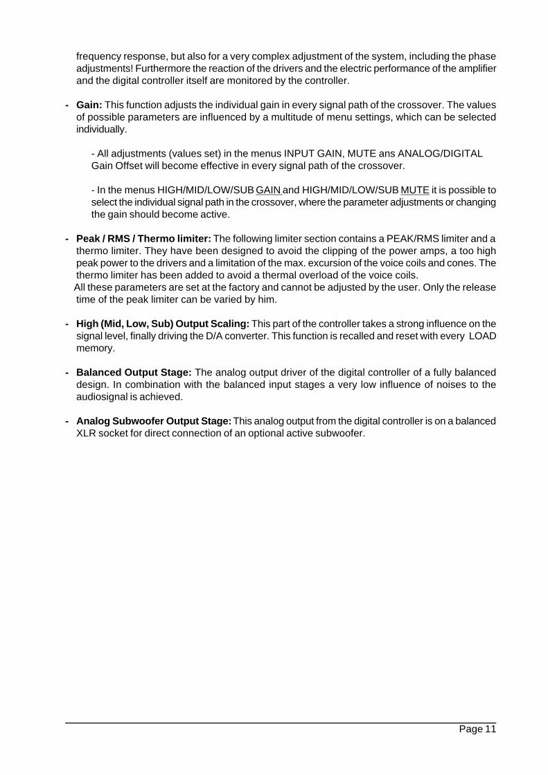
For the best result it should be taken into accountthat the main direction of dispersion of the O500 C corresponds to the axis vertically betweenmidrange system and tweeter.When positioning the monitor please make sureto select the right height for the speaker position,which can be adjusted / corrected by using thetilting adaptor LH 36. Fig. 2.1/1 shows thedimensions and the positioning of the mountingpoints on the bottom and the sides.
Mounting on a tripod
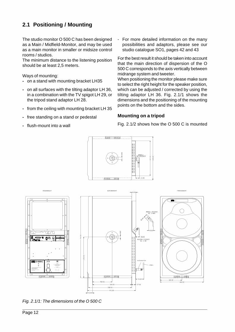
Fig. 2.1/2 shows how the O 500 C is mounted
Fig. 2.1/1: The dimensions of the O 500 C
RESET
Rear panel may become too hot
to touch
ANALOG INPUTSERIAL PORT
DIGITAL S/P-DIFINPUT
DIGITAL AES/EBUINPUT THROUGH SUBWOOFER
Leave enough space for proper
ventilationHOT
This equipment is capable of delivering sound pressure
levels in excess of 90 dB/SPL, which may cause permanent hearing damage.
CAUTION!To prevent the risk of fire and shock hazard don´t expose
this appliance to moisture and rain.Do not remove rear panel.
Refer to qualified service personnel for service.No user serviceable parts inside.
SB 6,3 A
T 3,15 A
CAUTION!Replace fuse only with same type and rating
transformer balanced
RS 232 IN MIDI IN / MIDI OUT
electr. balanced
INPUTSECTION
PIN 1 = PIN 2 = PIN 3 =
+
-
Choose electronically balanced input for
optimized performance
PIN 1 = PIN 2 = PIN 3 =
HIGH RESOLUTION MIDFIELD REFERENCE MONITOR3 AMPLIFIER POWERED SYSTEM24 BIT, FIR-FILTER-CONTROLLEDMAGNETICALLY SHIELDED
O 500 CKLEIN+HUMMEL
KLEIN+HUMMEL GmbH D-73760 OstfildernMADE IN GERMANY
GROUND
CONNECTED LIFTED
POWER
AC 50 - 60 Hz Max. power consumption 1500 VA
MAINS
AC 117 V~
AC 230 V~
WARNING!
Page 13
on the tilting adaptor LH36, which is fixed to thebottom of the cabinet. When adding the TV-adaptor LH29 or the tripod stand adaptor LH28,the monitor can be mounted on a speaker stand.Alternatively it is possible to use the U-shapedmounting bracket LH 35, which has its threadedholes on the side of the cabinet. Here, too, it ispossible to add the LH 29 and LH 28 for mountingthe monitor on a speaker stand. With the LH 35mounting bracket it is also possible to have theO 500 C mounted from the ceiling ( may needadditional adaptors, depending on theconstruction ).
Horizontal operation
In some cases a vertical operation of themonitors may not be possible, due to lack ofspace or for architectural reasons. For this caseK+H offers a special version for horizontaloperation ( please specify for horn LEFT / hornRIGHT ) where the horn is rotated by 90degrees, and special heatsinks are provided to
follow this type of operation. This way the heatdissipation from the power amps is maintainedoptimized. Monitors in this version have to beordered specially at the factory, a localconversion is not possible.
Flush mount into a wall
The O 500 C can also be flush mounted into awall or other areas where limited or no airflowcan be provided. For these cases K+H offers aspecial wall-mount adaptor kit, which willaccomodate the O 500 C electronics and anextension cable for the speaker connectors. Nowthe electronics can be mounted in an area withbetter air circulation. The O 500 C can be orderedwith this option at the factory, but it is alsopossible to make a local change after installationwith the wall mount kit.
Fig. 2.1/2: Mounting of the tilting adaptor LH36
Page 14
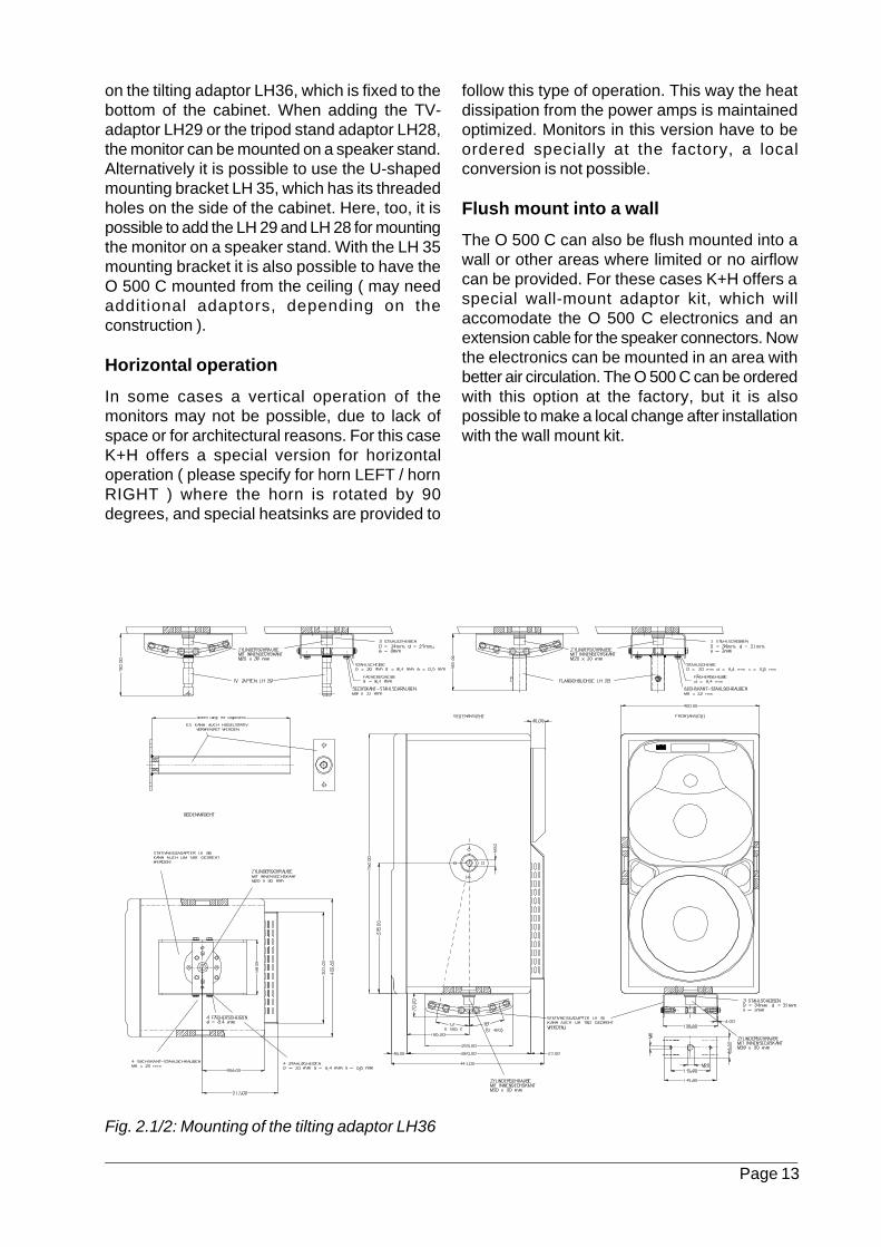
Fig. 2.1/3: Fixing holes for mounting LH 35 bracket
2.2 Connectors and Wiring
2.2.1 The connectors on the rear panel
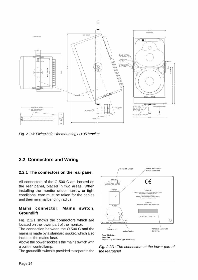
All connectors of the O 500 C are located onthe rear panel, placed in two areas. Wheninstalling the monitor under narrow or tightconditions, care must be taken for the cablesand their minimal bending radius.
Mains connector, Mains switch,Groundlift
Fig. 2.2/1 shows the connectors which arelocated on the lower part of the monitor.The connection between the O 500 C and themains is made by a standard socket, which alsoincludes the mains fuse.Above the power socket is the mains switch witha built-in controllamp.The groundlift switch is provided to separate the
Fig. 2.2/1: The connectors at the lower part ofthe rearpanel
CAUTION!To prevent the risk of fire and shock hazard don´t expose
this appliance to moisture and rain.Do not remove rear panel.
Refer to qualified service personnel for service.No user serviceable parts inside.
SB 6,3 A
T 3,15 A
CAUTION!Replace fuse only with same type and rating
GROUND
CONNECTED LIFTED
POWER
AC 50 - 60 Hz Max. power consumption 1500 VA
MAINS
AC 117 V~
AC 230 V~
Groundlift-Switch Mains Switch withPower-ON Lamp
Fuse SB 6,3 AAttention!Replace only with same Type and Rating!
Fuse HolderMains Socked
Adhesive Label withSerial No.
Page 15
internal ground from the mains earth, just in casethere should be any hum problems occuring dueto different potentials between the connectedunits.
Signal connections
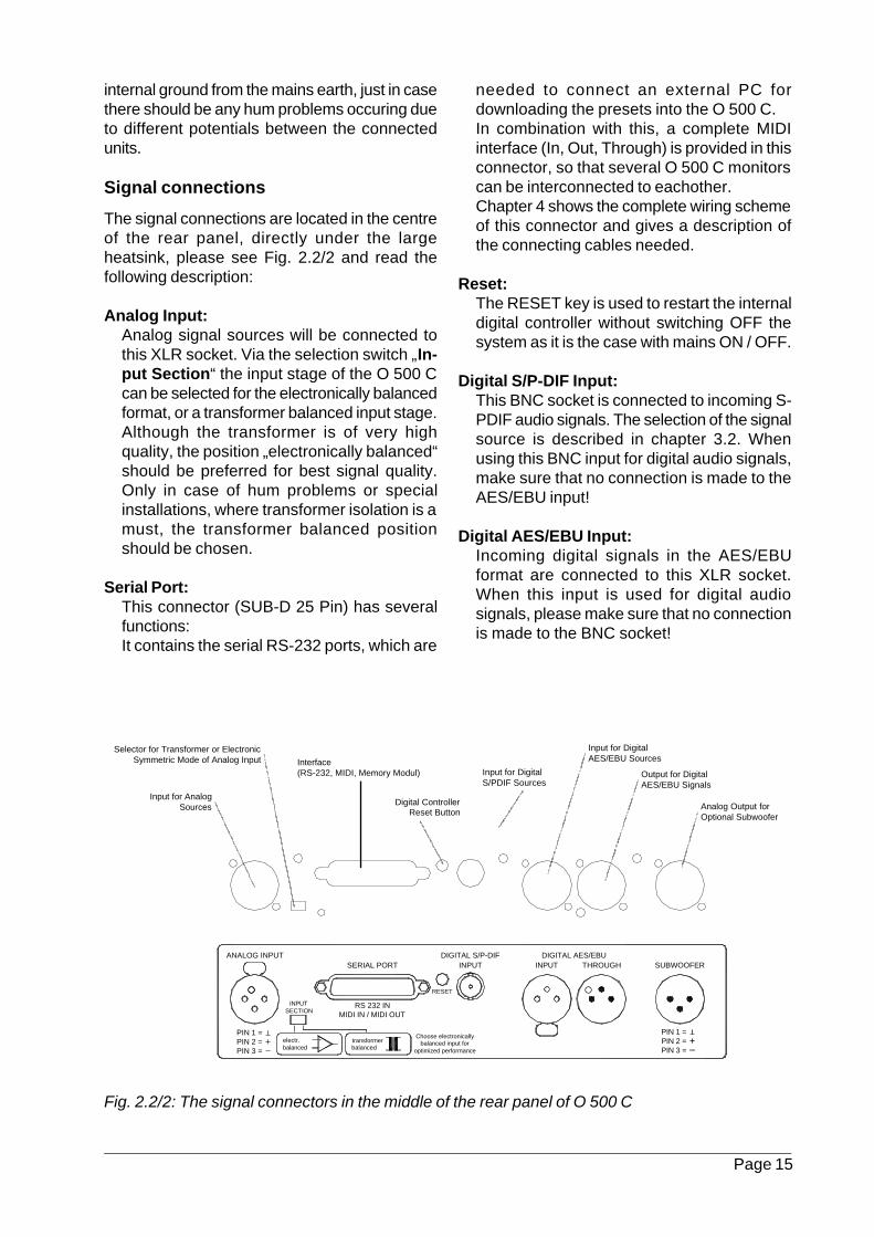
The signal connections are located in the centreof the rear panel, directly under the largeheatsink, please see Fig. 2.2/2 and read thefollowing description:
Analog Input:Analog signal sources will be connected tothis XLR socket. Via the selection switch „In-put Section“ the input stage of the O 500 Ccan be selected for the electronically balancedformat, or a transformer balanced input stage.Although the transformer is of very highquality, the position „electronically balanced“should be preferred for best signal quality.Only in case of hum problems or specialinstallations, where transformer isolation is amust, the transformer balanced positionshould be chosen.
Serial Port:This connector (SUB-D 25 Pin) has severalfunctions:It contains the serial RS-232 ports, which are
Fig. 2.2/2: The signal connectors in the middle of the rear panel of O 500 C
needed to connect an external PC fordownloading the presets into the O 500 C.In combination with this, a complete MIDIinterface (In, Out, Through) is provided in thisconnector, so that several O 500 C monitorscan be interconnected to eachother.Chapter 4 shows the complete wiring schemeof this connector and gives a description ofthe connecting cables needed.
Reset:The RESET key is used to restart the internaldigital controller without switching OFF thesystem as it is the case with mains ON / OFF.
Digital S/P-DIF Input:This BNC socket is connected to incoming S-PDIF audio signals. The selection of the signalsource is described in chapter 3.2. Whenusing this BNC input for digital audio signals,make sure that no connection is made to theAES/EBU input!
Digital AES/EBU Input:Incoming digital signals in the AES/EBUformat are connected to this XLR socket.When this input is used for digital audiosignals, please make sure that no connectionis made to the BNC socket!
RESET
ANALOG INPUTSERIAL PORT
DIGITAL S/P-DIFINPUT
DIGITAL AES/EBUINPUT THROUGH SUBWOOFER
transformer balanced
RS 232 IN MIDI IN / MIDI OUT
electr. balanced
INPUTSECTION
PIN 1 = PIN 2 = PIN 3 =
+
-
Choose electronically balanced input for
optimized performance
PIN 1 = PIN 2 = PIN 3 =
Input for AnalogSources
Selector for Transformer or ElectronicSymmetric Mode of Analog Input
Input for DigitalAES/EBU Sources
Output for DigitalAES/EBU Signals
Analog Output forOptional Subwoofer
Interface(RS-232, MIDI, Memory Modul) Input for Digital
S/PDIF Sources
Digital ControllerReset Button
Page 16
Digital AES/EBU through:This XLR socket will carry a parallel digitaloutput signal, which is fed either to the BNCor XLR digital input. There will be a formatconversion inside the O 500 C, so any S-PDIFsignal in the BNC input will be an AES/EBUsignal on that XLR output. This signal maynow be fed to a second O 500 C and the usermay select for the L or R channel from thedigital data stream.
Subwoofer:This XLR output will carry the analog outputsignal from the digital controller, which isprovided for an external, optional subwoofer.This output will only be active, if a special 4-way setup has been loaded for the O 500 C.
2.2.2 Variety of Connections
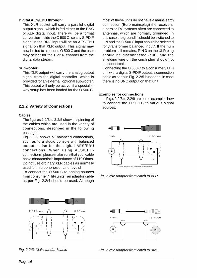
CablesThe figures 2.2/3 to 2.2/5 show the pinning ofthe cables which are used in the variety ofconnections, described in the followingpassages:Fig. 2.2/3 shows all balanced connections,such as to a studio console with balancedoutputs, also for the digital AES/EBUconnections. When using AES/EBU-connections, please make sure that your cablehas a characteristic impedance of 110 Ohms.Do not use ordinary XLR cables as normallyused for microphones or Line-levels!To connect the O 500 C to analog sourcesfrom consumer / HiFi units, an adaptor cableas per Fig. 2.2/4 should be used. Although
Fig. 2.2/4: Adapter from cinch to XLR
Fig. 2.2/5: Adapter from cinch to BNCFig. 2.2/3: XLR standard cable
most of these units do not have a mains earthconnection (Euro mainsplug) the receivers,tuners or TV-systems often are connected toantennas, which are normally grounded. Inthis case the groundlift should be switched toON and the O 500 C input should be selectedfor „transformer balanced input“. If the humproblem still remains, PIN 3 on the XLR plugshould be disconnected (cut), and theshielding wire on the cinch plug should notbe connected.Connecting the O 500 C to a consumer / HiFiunit with a digital S-PDIF output, a connectioncable as seen in Fig. 2.2/5 is needed, in casethere is no BNC output on that unit.
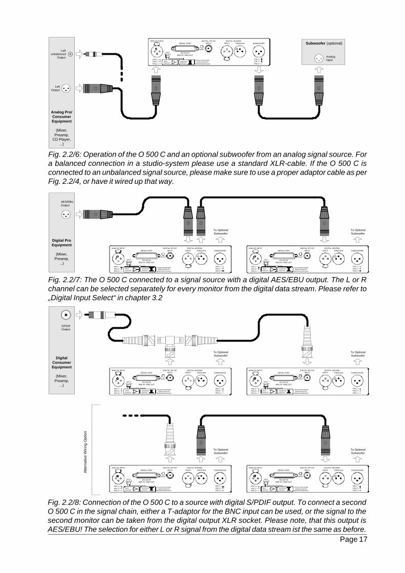
Examples for connectionsIn Fig.s 2.2/6 to 2.2/9 are some examples howto connect the O 500 C to various signalsources.
1 1
2 2
3 3
XLR-3 female XLR-3 male
1
2
3
Cinch XLR-3 male
Break Bridge in Case of Humm & Buzz Problems!
Cinch BNC Jack
Page 17
Fig. 2.2/6: Operation of the O 500 C and an optional subwoofer from an analog signal source. Fora balanced connection in a studio-system please use a standard XLR-cable. If the O 500 C isconnected to an unbalanced signal source, please make sure to use a proper adaptor cable as perFig. 2.2/4, or have it wired up that way.
Fig. 2.2/7: The O 500 C connected to a signal source with a digital AES/EBU output. The L or Rchannel can be selected separately for every monitor from the digital data stream. Please refer to„Digital Input Select“ in chapter 3.2
Fig. 2.2/8: Connection of the O 500 C to a source with digital S/PDIF output. To connect a secondO 500 C in the signal chain, either a T-adaptor for the BNC input can be used, or the signal to thesecond monitor can be taken from the digital output XLR socket. Please note, that this output isAES/EBU! The selection for either L or R signal from the digital data stream ist the same as before.
Digital ProEquipment
(Mixer,Preamp,
...)
RESET
ANALOG INPUTSERIAL PORT
DIGITAL S/P-DIFINPUT
DIGITAL AES/EBUINPUT THROUGH SUBWOOFER
transformer balanced
RS 232 IN MIDI IN / MIDI OUT
electr. balanced
INPUTSECTION
PIN 1 = PIN 2 = PIN 3 =
+-
Choose electronically balanced input for
optimized performance
PIN 1 = PIN 2 = PIN 3 =
RESET
ANALOG INPUTSERIAL PORT
DIGITAL S/P-DIFINPUT
DIGITAL AES/EBUINPUT THROUGH SUBWOOFER
transformer balanced
RS 232 IN MIDI IN / MIDI OUT
electr. balanced
INPUTSECTION
PIN 1 = PIN 2 = PIN 3 =
+-
Choose electronically balanced input for
optimized performance
PIN 1 = PIN 2 = PIN 3 =
AES/EBUOutput
To OptionalSubwoofer
To OptionalSubwoofer
DigitalConsumerEquipment
(Mixer,Preamp,
...)
RESET
ANALOG INPUTSERIAL PORT
DIGITAL S/P-DIFINPUT
DIGITAL AES/EBUINPUT THROUGH SUBWOOFER
transformer balanced
RS 232 IN MIDI IN / MIDI OUT
electr. balanced
INPUTSECTION
PIN 1 = PIN 2 = PIN 3 =
+
-
Choose electronically balanced input for
optimized performance
PIN 1 = PIN 2 = PIN 3 =
RESET
ANALOG INPUTSERIAL PORT
DIGITAL S/P-DIFINPUT
DIGITAL AES/EBUINPUT THROUGH SUBWOOFER
transformer balanced
RS 232 IN MIDI IN / MIDI OUT
electr. balanced
INPUTSECTION
PIN 1 = PIN 2 = PIN 3 =
+
-
Choose electronically balanced input for
optimized performance
PIN 1 = PIN 2 = PIN 3 =
S/PDIFOutput
RESET
ANALOG INPUTSERIAL PORT
DIGITAL S/P-DIFINPUT
DIGITAL AES/EBUINPUT THROUGH SUBWOOFER
transformer balanced
RS 232 IN MIDI IN / MIDI OUT
electr. balanced
INPUTSECTION
PIN 1 = PIN 2 = PIN 3 =
+
-
Choose electronically balanced input for
optimized performance
PIN 1 = PIN 2 = PIN 3 =
RESET
ANALOG INPUTSERIAL PORT
DIGITAL S/P-DIFINPUT
DIGITAL AES/EBUINPUT THROUGH SUBWOOFER
transformer balanced
RS 232 IN MIDI IN / MIDI OUT
electr. balanced
INPUTSECTION
PIN 1 = PIN 2 = PIN 3 =
+
-
Choose electronically balanced input for
optimized performance
PIN 1 = PIN 2 = PIN 3 =
Alte
rnat
ive
Wiri
ng O
ptio
n
To OptionalSubwoofer
To OptionalSubwoofer
To OptionalSubwoofer
To OptionalSubwoofer
Analog Pro/ConsumerEquipment
(Mixer,Preamp,
CD Player,...)
RESET
ANALOG INPUTSERIAL PORT
DIGITAL S/P-DIFINPUT
DIGITAL AES/EBUINPUT THROUGH SUBWOOFER
transformer balanced
RS 232 IN MIDI IN / MIDI OUT
electr. balanced
INPUTSECTION
PIN 1 = PIN 2 = PIN 3 =
+
-
Choose electronically balanced input for
optimized performance
PIN 1 = PIN 2 = PIN 3 =
LeftOutput
AnalogInput
Subwoofer (optional)
Leftunbalanced
Output
Page 18
2.4 Recall of the Loudspeaker Parameter Setup
The O 500 C is supplied with factory presets ofall loudspeaker-relevant parameters like speakerequalization, limiter settings,... which are storedin a Flash-ROM of the digital controller. Additio-nal parameter presets can be ordered at extracharge, or can be determined on the installation-site of the monitors and copied into the Flash-ROM (Room eqalization).During the first installation of the monitor it hasto be checked, whether the right preset has beenactivated. If not, the correct Loudspeaker Para-meter Setup has to be looked up and recalledinto the system.
The O 500 C is operated by the IR-remotecontroller RC 55.The procedure is as follows:- Switch ON the monitor with the power switch
on the rear panel
- Wait until the digital controller has booted andthe K + H Logo is illuminated
- The menu „Input Gain“ appears in the display,showing a default dB-value
- By pressing the numeric key „8“ on the RC55 the menu step 8 Speaker Select willbecome active, the display will now show
„Monitor/Subwoofer“.
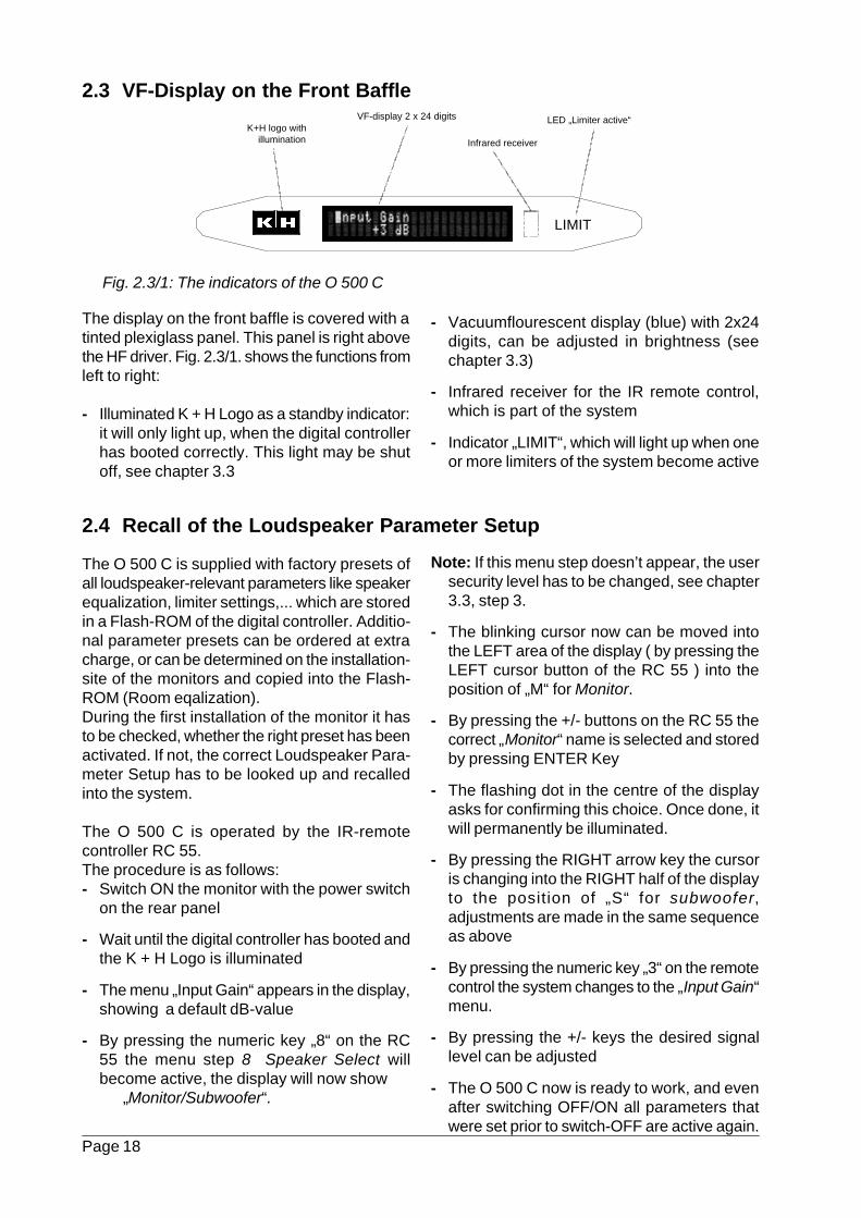
Fig. 2.3/1: The indicators of the O 500 C
The display on the front baffle is covered with atinted plexiglass panel. This panel is right abovethe HF driver. Fig. 2.3/1. shows the functions fromleft to right:
- Illuminated K + H Logo as a standby indicator:it will only light up, when the digital controllerhas booted correctly. This light may be shutoff, see chapter 3.3
- Vacuumflourescent display (blue) with 2x24digits, can be adjusted in brightness (seechapter 3.3)
- Infrared receiver for the IR remote control,which is part of the system
- Indicator „LIMIT“, which will light up when oneor more limiters of the system become active
Note: If this menu step doesn’t appear, the usersecurity level has to be changed, see chapter3.3, step 3.
- The blinking cursor now can be moved intothe LEFT area of the display ( by pressing theLEFT cursor button of the RC 55 ) into theposition of „M“ for Monitor.
- By pressing the +/- buttons on the RC 55 thecorrect „Monitor“ name is selected and storedby pressing ENTER Key
- The flashing dot in the centre of the displayasks for confirming this choice. Once done, itwill permanently be illuminated.
- By pressing the RIGHT arrow key the cursoris changing into the RIGHT half of the displayto the position of „S“ for subwoofer,adjustments are made in the same sequenceas above
- By pressing the numeric key „3“ on the remotecontrol the system changes to the „Input Gain“menu.
- By pressing the +/- keys the desired signallevel can be adjusted
- The O 500 C now is ready to work, and evenafter switching OFF/ON all parameters thatwere set prior to switch-OFF are active again.
2.3 VF-Display on the Front Baffle
K+H logo withillumination Infrared receiver
VF-display 2 x 24 digits
LIMIT
LED „Limiter active“
KLEIN + HUMMELO 500 C
Page 19
3.1 Menu Structure and Conceptof Operation
The operation of the O 500 C digital controller isbased on a special menu structure, where theindividual menu steps have been concentratedinto three main menus:
- Main Menu (Chapter 3.2): This menuincludes the most needed control functionsfor the normal operation of the monitor, suchas the level setting for the input signals, settingand recall of setups, adjustement of internaldelay and finally the choice of the desiredLoudspeaker parameter setups which arestored in the Flash-ROM.
- System Menu (Chapter 3.3): This menucontains the basic settings of software andhardware, which are used occasionally, suchas configuration of the MIDI channel,passwords for the user levels etc.
- EQ Menu (Chapter 3.4): This menu iscompletely reserved for the setups andadjustments of the integrated Room- andparametric EQs, where changes in the overallfrequency response can be made, such asthe line-up procedure for adjustments in thecontrol room.
Recall and adjustments of the individual menuswill be made via the IR-remote control unit RC55, see chapter 4.1.
- Menu selection keys: Sys - Main - EQ forselection of the menu
- four ARROW keys: UP - DOWN - LEFT -RIGHT for navigation through the individualpoints within a menu
- the two +/- increment keys located under theL/R arrow keys will be used for adjusting theparameters of the selected functions
- The ENTER key in the centre of the arrow-keys
The other keys of the IR remote control will beexplained in chapter 4.1 .
When selecting any of the menu sections thesystem will show the headline of the relevantmenu. When pressing the MAIN key for example
the „K + H O 500 C Main Menu“ headline willappear in the VF-display of the O 500 C.
From this headline all visible ( activated for theuser ) menupoints can be recalled by pressingthe DOWN arrow-key. to get back to theheadline, simply press the UP arrow key.
When a menu point has been activated, thename of the menu will appear in the left part of
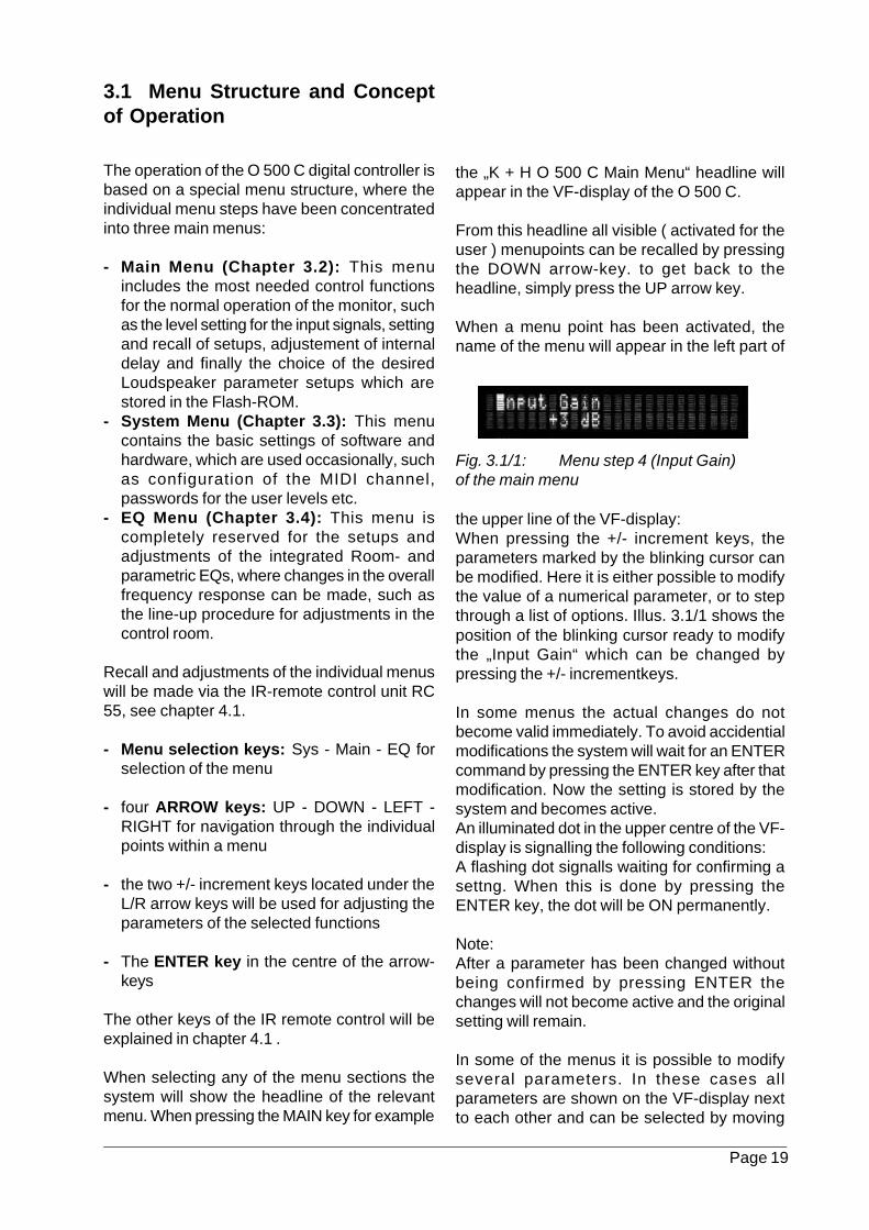
Fig. 3.1/1: Menu step 4 (Input Gain)of the main menu
the upper line of the VF-display:When pressing the +/- increment keys, theparameters marked by the blinking cursor canbe modified. Here it is either possible to modifythe value of a numerical parameter, or to stepthrough a list of options. Illus. 3.1/1 shows theposition of the blinking cursor ready to modifythe „Input Gain“ which can be changed bypressing the +/- incrementkeys.
In some menus the actual changes do notbecome valid immediately. To avoid accidentialmodifications the system will wait for an ENTERcommand by pressing the ENTER key after thatmodification. Now the setting is stored by thesystem and becomes active.An illuminated dot in the upper centre of the VF-display is signalling the following conditions:A flashing dot signalls waiting for confirming asettng. When this is done by pressing theENTER key, the dot will be ON permanently.
Note:After a parameter has been changed withoutbeing confirmed by pressing ENTER thechanges will not become active and the originalsetting will remain.
In some of the menus it is possible to modifyseveral parameters. In these cases allparameters are shown on the VF-display nextto each other and can be selected by moving
Page 20
the blinking cursor with the LEFT and RIGHTarrow key.
There are some menus which offer a largernumber of parameters which would not fit ontothe VF-display. In these cases the menu isspread onto several subpages.The menu points with a subpage are markedwith an arrow in the upper right corner of thedisplay, if there are more than one pages therewill be a double arrow shown.To get to the next subpage the cursor can bemoved by the LEFT or RIGHT cursor key, whichthen will be displayed.Examples for the splitting of one menu point intoseveral subpages can be seen in points 10...13of the main menu.
This general description of the operation is validfor all menus.
Remarks:
The listing in the following chapterscontains all menu points of the O 500 Csoftware. The selected user security levelaffects the relevant menus, which can bedisplayed and modified (see system menuchapter 3.3, step 3). These are marked withan “X” in the following overwiews.
Page 21
3.2 Main Menu
(Eprom-Version-Nr. KH 1.038)
Explanation of Menu Steps:
K+H O 500 C - Main Menu -
(Menu headline)
1 Load SetupIn this menu the setups can be recalled. Asetup contains all settings in all menu stepsof the main and EQ menu, with the exceptionof the menu step 3 Input Gain. It also containsthe status of the logo illumination (ON/OFF,see system menu). By pressing the +/-increment keys it is possible to scroll throughthe options, until the name of the desiredsetup is displayed, which now can be recalledby pressing ENTER.
2 Store SetupTo store modified settings of the main menuand EQ menu in a new SETUP, select EnterSetup Name by pressing the ENTER key.Now it is possible to select a character A, a,O with the DOWN arrow key and then selectthe desired characters or numbers bypressing the +/- increment keys. With theLEFT / RIGHT - arrow keys the cursor canbe moved between the individual letters ofthe word. After entering the desired name thenumber of the setup is selected by theincrement key in the menu Enter Setup No. .Finally press the ENTER key to store themodifications. The setup can be recalled
under 1 Load Setup, as described above. Themenu point Input Gain is not included in thesettings of a setup, so the actual listening levelremains constant when selecting a new one,or toggeling between two setups. If setupswith different levels are wanted, these can beadjusted and stored in the menu Gain Offsetindividually for the analog and digital signalinput.Note: the menu point STORE SETUP can beleft at any time by pressing the SYSTEMMENU key.Important note: All setups and the currentadjustments of all menu points will be storedin the SRAM of the digital controller. Whenthe monitor is switched OFF, the SRAM willbe powered by the internal buffer battery. Thislithium battery has a life of several years andshould only be replaced by skilled engineersaccording to the factory recommendations!
3 Input GainIn this menu the anaolog and/or digital inputlevel will be changed. When the O 500 C isswitched ON, this level will be automaticallyrecalled.
4 Gain OffsetIn this menu it is possible to store differentinput levels for the analog and digital inputs.Looking at the signal flow of the unit, it can
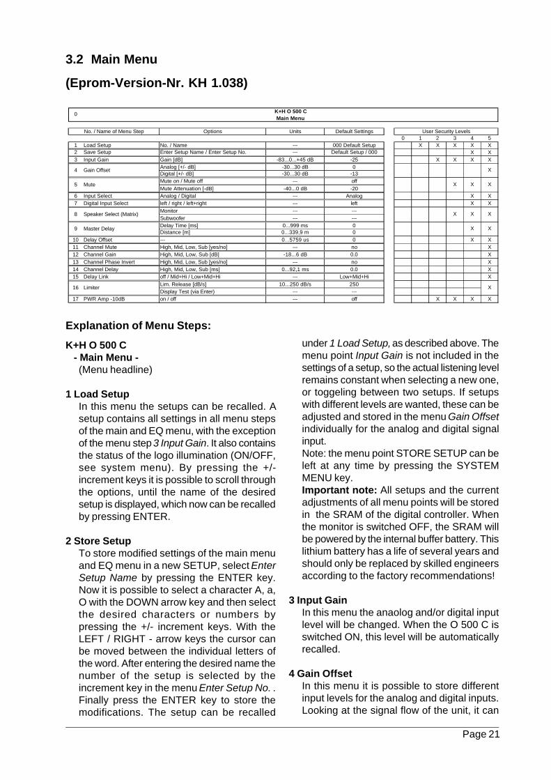
Options Units Default Settings0 1 2 3 4 5
1 Load Setup No. / Name --- 000 Default Setup X X X X X2 Save Setup Enter Setup Name / Enter Setup No. --- Default Setup / 000 X X3 Input Gain Gain [dB] -83...0...+45 dB -25 X X X X
Analog [+/- dB] -30...30 dB 0Digital [+/- dB] -30...30 dB -13Mute on / Mute off --- offMute Attenuation [-dB] -40...0 dB -20
6 Input Select Analog / Digital --- Analog X X7 Digital Input Select left / right / left+right --- left X X
Monitor --- ---Subwoofer --- ---Delay Time [ms] 0...999 ms 0Distance [m] 0...339,9 m 0
10 Delay Offset --- 0...5759 us 0 X X11 Channel Mute High, Mid, Low, Sub [yes/no] --- no X12 Channel Gain High, Mid, Low, Sub [dB] -18...6 dB 0.0 X13 Channel Phase Invert High, Mid, Low, Sub [yes/no] --- no X14 Channel Delay High, Mid, Low, Sub [ms] 0...92,1 ms 0.0 X15 Delay Link off / Mid+Hi / Low+Mid+Hi --- Low+Mid+Hi X
Lim. Release [dB/s] 10...250 dB/s 250Display Test (via Enter) --- ---
17 PWR Amp -10dB on / off --- off X X X X
9
16
Speaker Select (Matrix)
Mute
Gain Offset
5
4
8
Limiter
Master Delay
0 K+H O 500 CMain Menu
X X
X
X X
X
X
X
No. / Name of Menu Step User Security Levels
X
X
Page 22
be seen that this level setting is done at thesame location as the Input Gain.
5 MuteWhen MUTE is activated, the level will bereduced by the value preselected in the MuteAttenuation menu.
6 Input SelectIn this menu the analog or digital input isactivated. When selecting digital, the 500 Cwill be triggered by the signal source, theinternal clock generator is deactivated.
7 Digital Input SelectIn this menu the L or R channel may beselected from the digital datastream. In a nor-mal stereo-setup the LEFT monitor will havethe selection LEFT and the RIGHT monitorwill be selected for RIGHT.In the setting „LEFT + RIGHT“ the systemwill generate and reproduce a mono sum ofboth channels.
8 Speaker SelectIn this menu the loudspeaker parameter setupwill be recalled. At „Monitor“ and „Subwoofer“the desired presets can be selected bypressing the +/- increment keys, followed byENTER to load the settings. A signal beepwill confirm this selection, which also can bemade during reproduction of a signal. If theselected loudspeaker parameter setup cannot be recalled, the system will respond withthe notice: „not available“ after pressing theENTER key. The parameters previously setwill remain active in this case.
9 Master DelayIn this menu the signal fed through the O 500C can be delayed either in milliseconds ormeters. The shortest delaytime is determinedby the basic delay time of the digital controllerwhich depends on the selected loudspeakerparameter setup. Based on that basic timethe delaytime may be varied by max. 999 mS,which is equal to 339,90 meters.
10 Delay OffsetThis menu adjusts the overall delay of themonitor in very small steps. It will adjust thebasic delaytime of the monitor in amultichannel setup.
11 Channel MuteIn this menu step each signal path (High, Mid,Low and the optional subwoofer) can bemuted. Changing the status (Mute on/off) ismade by the +/- increment keys of the remotecontrol.
12 Channel GainThis menu adjusts the gain of every path bymax. +6/-18 dB. Regarding the selection ofthe channel, the same options are providedas described above.
13 Channel Phase InvertIn this menu the pase of everey signal pathcan be inverted by 180°. Here the sameoptions for adjustments are provided as inthe previous menus.
14 Channel DelayThis menu adjusts an individual delay timefor every signal path after the electroniccrossover, for example the compensation fordifferent delay times between the O 500 Cand an optional subwoofer.
15 Delay LinkIn this menu the individual signal paths forthe adjustments as described in the ChannelDelay menu can be combined for ease ofoperation, i.e. adjusting all three signals atthe same time.
16 LimiterThis menu allows for a change of the release-time constant of the internal peaklimiter whichprevents the system from clipping of thepower amps and from too long excursions ofthe cones. The desired value is selected bypressing the +/- increment keys.
17 PWR Amp -10 dBWhen selecting the option „ON“ the gain ofthe O 500 C power amps is reduced by 10dB. When operating the system at lowlistening levels this option should be selectedto increase the word length of the digital signalgiven to the digital controller’s DACs.
Page 23
3.3 System Menu
(Eprom-Version-Nr. KH 1.038)
Description of the Menu Steps:
K+H O 500 C - System Menu -
Menu headline
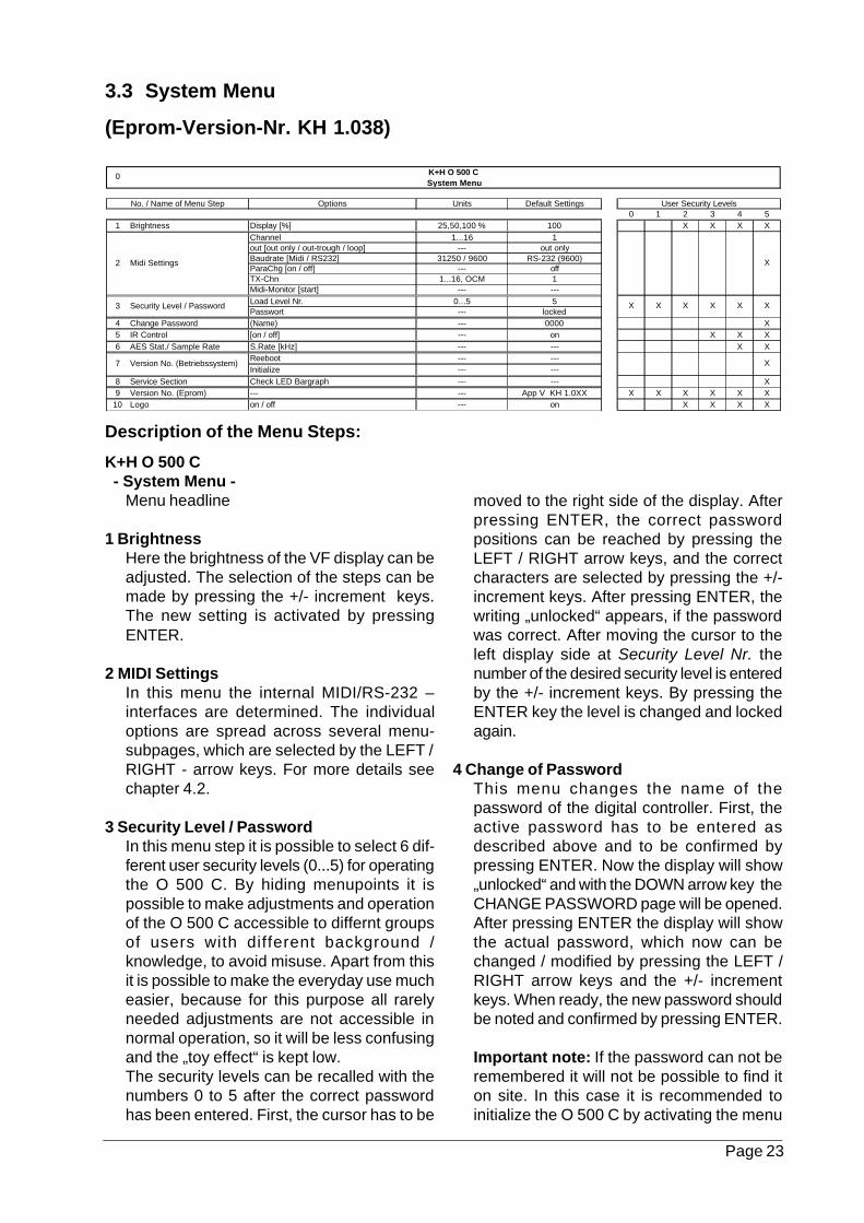
1 BrightnessHere the brightness of the VF display can beadjusted. The selection of the steps can bemade by pressing the +/- increment keys.The new setting is activated by pressingENTER.
2 MIDI SettingsIn this menu the internal MIDI/RS-232 –interfaces are determined. The individualoptions are spread across several menu-subpages, which are selected by the LEFT /RIGHT - arrow keys. For more details seechapter 4.2.
3 Security Level / PasswordIn this menu step it is possible to select 6 dif-ferent user security levels (0...5) for operatingthe O 500 C. By hiding menupoints it ispossible to make adjustments and operationof the O 500 C accessible to differnt groupsof users with different background /knowledge, to avoid misuse. Apart from thisit is possible to make the everyday use mucheasier, because for this purpose all rarelyneeded adjustments are not accessible innormal operation, so it will be less confusingand the „toy effect“ is kept low.The security levels can be recalled with thenumbers 0 to 5 after the correct passwordhas been entered. First, the cursor has to be
moved to the right side of the display. Afterpressing ENTER, the correct passwordpositions can be reached by pressing theLEFT / RIGHT arrow keys, and the correctcharacters are selected by pressing the +/-increment keys. After pressing ENTER, thewriting „unlocked“ appears, if the passwordwas correct. After moving the cursor to theleft display side at Security Level Nr. thenumber of the desired security level is enteredby the +/- increment keys. By pressing theENTER key the level is changed and lockedagain.
4 Change of PasswordThis menu changes the name of thepassword of the digital controller. First, theactive password has to be entered asdescribed above and to be confirmed bypressing ENTER. Now the display will show„unlocked“ and with the DOWN arrow key theCHANGE PASSWORD page will be opened.After pressing ENTER the display will showthe actual password, which now can bechanged / modified by pressing the LEFT /RIGHT arrow keys and the +/- incrementkeys. When ready, the new password shouldbe noted and confirmed by pressing ENTER.
Important note: If the password can not beremembered it will not be possible to find iton site. In this case it is recommended toinitialize the O 500 C by activating the menu
Options Units Default Settings0 1 2 3 4 5
1 Brightness Display [%] 25,50,100 % 100 X X X XChannel 1...16 1out [out only / out-trough / loop] --- out onlyBaudrate [Midi / RS232] 31250 / 9600 RS-232 (9600)ParaChg [on / off] --- offTX-Chn 1...16, OCM 1Midi-Monitor [start] --- ---Load Level Nr. 0...5 5Passwort --- locked
4 Change Password (Name) --- 0000 X5 IR Control [on / off] --- on X X X6 AES Stat./ Sample Rate S.Rate [kHz] --- --- X X
Reeboot --- ---Initialize --- ---
8 Service Section Check LED Bargraph --- --- X9 Version No. (Eprom) --- --- App V KH 1.0XX X X X X X X
10 Logo on / off --- on X X X X
3 Security Level / Password
2
No. / Name of Menu Step
Midi Settings
7 Version No. (Betriebssystem)
X
K+H O 500 C 0System Menu
X X X
X
X X
X
User Security Levels
Page 24
Version No. in the Sys-Menu or by holdingdown the ENTER key when switching ON themonitor. Now the password is set to thedefault value 0000. Attention: This reset alsoaffects all the adjustments in the menus whichhave been made by the user, only theloudspeaker parameter setups which arestored in the Flash Rom will remain. (pleasesee the menu „Default adjustments“).
5 IR ControlIn this menu the IR remote control can beswitched ON / OFF.
6 AES Stat. / Sample RateIn this menu the clock frequency is shown,which the O 500 C is locked to. In normalmode, this will be 44,1 kHz for S-PDIF or 48kHz for AES/EBU format. This is a straightstatus display, just for user information, andnon-adjustable.
7 Version No. (Operating System)In this menu the release number of theoperating system of the digital controller willbe displayed. In case of service this numbermay be needed for reference or updates.
When activating the option Reboot via theENTER key, the digital controller will boot likeit does if you power-up the O 500 C. Allsettings and presets in the individual menusremain active. When the option Initialize isselected, all individual settings in all menuswill be erased and the system will only workwith the default settings of the factory presets.When pressing the ENTER key an additionalconfirmation is necessary by pressing theMain key. Otherwise, it is possible to turn backby pressing the SYS key.
8 Service SectionThis menu has no function in the O 500 C.
9 Version No. (Eprom)In this menu the number of the DSP softwareversion will be displayed, which is stored inthe internal E-PROM.
10 LogoIn this menu it is possible to switch OFF theilluminated K+H logo, which is located on theleft of the VF display. This selection is storedin the main setup, too. (see Chapter 3.2, step1)
3.4 EQ – Menu
(Eprom-Version-No. KH 1.038)
Description of the menu steps:
K+H O 500 C - EQ Menu -
Menu headline
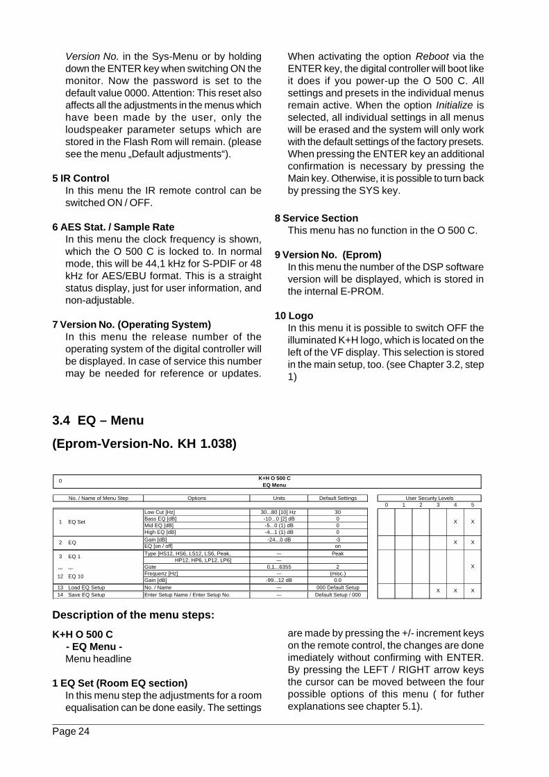
1 EQ Set (Room EQ section)In this menu step the adjustments for a roomequalisation can be done easily. The settings
are made by pressing the +/- increment keyson the remote control, the changes are doneimediately without confirming with ENTER.By pressing the LEFT / RIGHT arrow keysthe cursor can be moved between the fourpossible options of this menu ( for futherexplanations see chapter 5.1).
Options Units Default Settings0 1 2 3 4 5
Low Cut [Hz] 30...80 [10] Hz 30Bass EQ [dB] -10...0 [2] dB 0Mid EQ [dB] -5...0 (1) dB 0High EQ [dB] -4...1 (1) dB 0Gain [dB] -24...0 dB -3EQ [on / off] onType [HS12, HS6, LS12, LS6, Peak, --- Peak HP12, HP6, LP12, LP6] ---
... ... Güte 0,1...6355 2Frequenz [Hz] --- (misc.)Gain [dB] -99...12 dB 0.0
13 Load EQ Setup No. / Name --- 000 Default Setup14 Save EQ Setup Enter Setup Name / Enter Setup No. --- Default Setup / 000
EQ 10
3
2
12
EQ 1
1 EQ Set
EQ
X
X X
XX X
XX
User Security Levels
K+H O 500 CEQ Menu
No. / Name of Menu Step
0
Page 25
2 Gain / EQThe gain reduction to be made in this menuis calculated upon the max. gain increasemade in any frequency band which has beenadjusted in the menu EQ Set or EQ1...EQ10.By compensation of the signal gain at thisstage it is possible to avoid any overload inthe following signal stages. By selecting EQOFF all adjusted EQ settings in the EQ 1 ...EQ10 presets will be taken out of the signal flow.The adjustments made in EQ Gain are notbypassed, i.e. the preselected value remainsactive.
3 EQ1...12 EQ10 (PEQ section)Each of these 10 menu steps provides a fullyparameteric EQ band. The type of every bandcan be selected to be peak, shelving or low/highpass characteristics by moving the cursorto PEAK and then stepping throufg the optionsby pressing the LEFT / RIGHT arrow keys. Asetting is confirmed by pressing the ENTERkey. In PEAK mode the following options areaccessible: Q-factor, frequency and +/- gainin the mid band frequency. When selecting ashelving filter the -3 dB frequency and gaincan be adjusted. All of these settings are doneby moving the cursor to the desired positionand then changing the values by using the +/- inkrement keys. The settings are confirmedwithout using ENTER. For furtherexplanations see chapter 5.2.
13 Load EQ SetupIn this menu it is possible to store EQ setups.An EQ setup contains all adjustments of themenus 3 EQ1 ... 12 EQ10. To recall them,
simply press the +/- increment keys until thename of the desired setup appears in thedisplay. By pressing ENTER this preset willbe instantly recalled.
14 Store EQ SetupTo store modified settings of the EQ bands1...10 (PEQ section) in a new SETUP, selectEnter Setup Name by pressing the ENTERkey. Now it is possible to select a characterA, a, O with the DOWN arrow key and thenselect the desired characters or numbers bypressing the +/- increment keys. With theLEFT / RIGHT - arrow keys the cursor canbe moved between the individual letters ofthe word. After entering the desired name ithas to be confirmed with ENTER. After thatthe number of the setup is selected by theincrement key in the following menu EnterSetup No. . Finally press the ENTER againkey to store the modifications. The setup canbe recalled under 1 Load EQ Setup, asdescribed above.Note: the menu point STORE SETUP canbe left at any time by pressing the SYSTEMMENU key.Important note: All setups and the currentadjustments of all menu points will be storedin the SRAM of the digital controller. Whenthe monitor is switched OFF, the SRAM willbe powered by the internal buffer battery.This lithium battery has a life of several yearsand should only be replaced by skilledengineers according to the factoryrecommendations!
Page 26
4.1 Infrared Remote Control
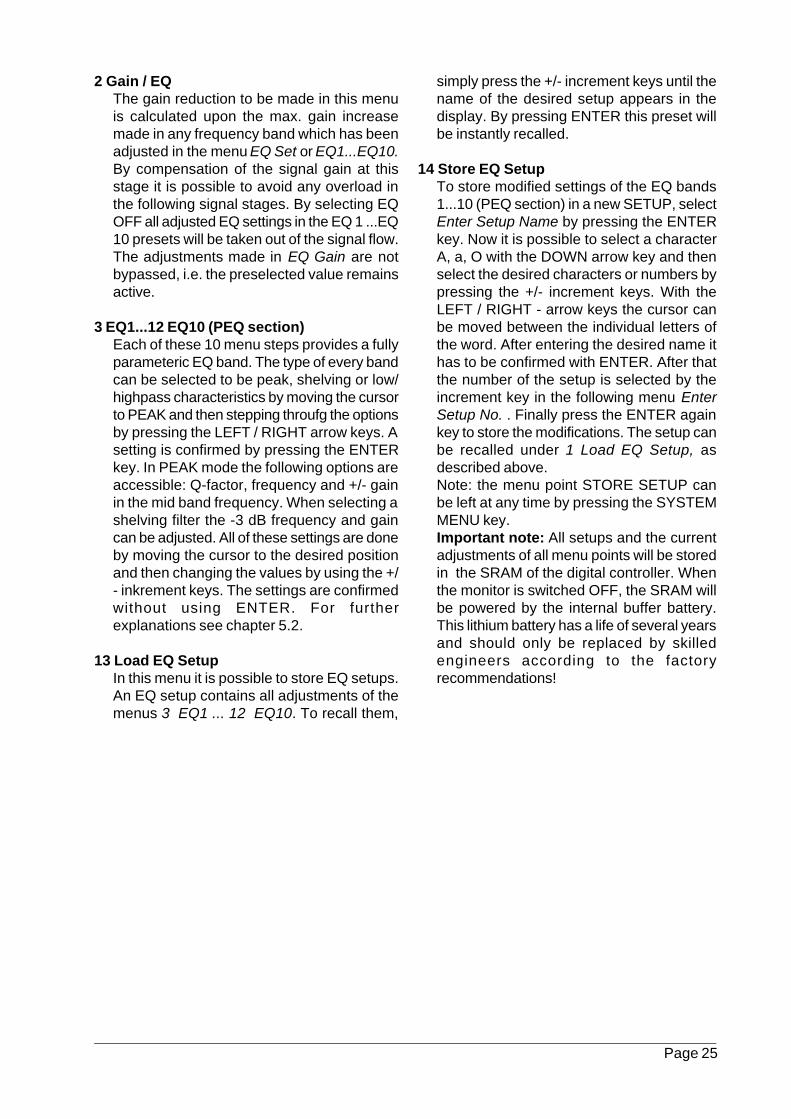
The IR remote control RC 55 is supplied withevery O 500 C monitor. Even when ordering apair or a 5.1 system, every O 500 C will have it’sown remote control. All RC 55 are identical, it isjust a matter of providing the user with a spareRC of the same type. The RC 55 remote controlhas 36 rubber keys, which are operating allfunctions of the O 500 C. In addition to thestandard controls such as menu select, cursorkeys and increment keys which have beendescribed before, a number of DIRECT ACCESSkeys are provided for controlling importantfunctions of the O 500 C.
Fig. 4.1/1 shows the layout of the keys. Thesilkscreening / naming of every key will explainthe individual keys:
Numeric keysWith the number keys (1 ... 0, *, #) the menu-steps of the selected menu (Main, Sys, EQ)can be recalled directly by typing in the relatedmenu number (can be looked up from theselection in chapter 3).Please note that only the visible menupointsof the activated user security level can berecalled!
Setup-KeysThese keys can be used to recall the mainsetups 1...4 which have been stored in menustep 2 of the Main menu (see chapter 3.2)
IR ON/OFFThis direct access key will allow for the ON /OFF switching of the IR remote control.
Room EQWhen pressing this key, the menu step 1 EQSet of the EQ-menu becomes active to adjustthe room EQ (see chapter 5.1) of the O 500C.
EQ ON/OFFWhen pressing this key, menu 2 EQ of theEQ-menu is activated and the EQ is switchedON / OFF.
-20 dBThis key will select the function 17 PWR Amp-10 dB as described in chapter 3.2 and willlower the listening level by 10 dB. Pressingagain will return to the original volume.
MuteWhen pressing MUTE, the function describedin 4 Mute of the main menu will reduce thesignal level by the value as adjusted in the„Mute Attenuation“ menu.
Vol+/Vol-With these keys the level of the monitor canbe adjusted. Pressing any of these two keyswill atomatically activate the menu Input Gainof the main menu. Any changes of the settingsin this menu do not need to be confirmed bypressing ENTER.
Fig. 4.1/1: The labelling of the IR- remotecontrol RC 55
KLEIN+HUMMEL
Setup 1 Setup 2 Setup 3 Setup 4
Mute
-20 dBSys Main EQ
1 2 3
4 5 6
7 8 9
0
IR on/off
RoomEQ
EQ on/off
+- Vol -
Vol +Enter
#
Page 27
The Sub-D socket on the rear of the O 500 Ccontains several interfaces of the internal digi-tal controller:
- MIDI-Interface with MIDI In, MIDI Out andMIDI Through
- RS-232 interface
- Interface for future options
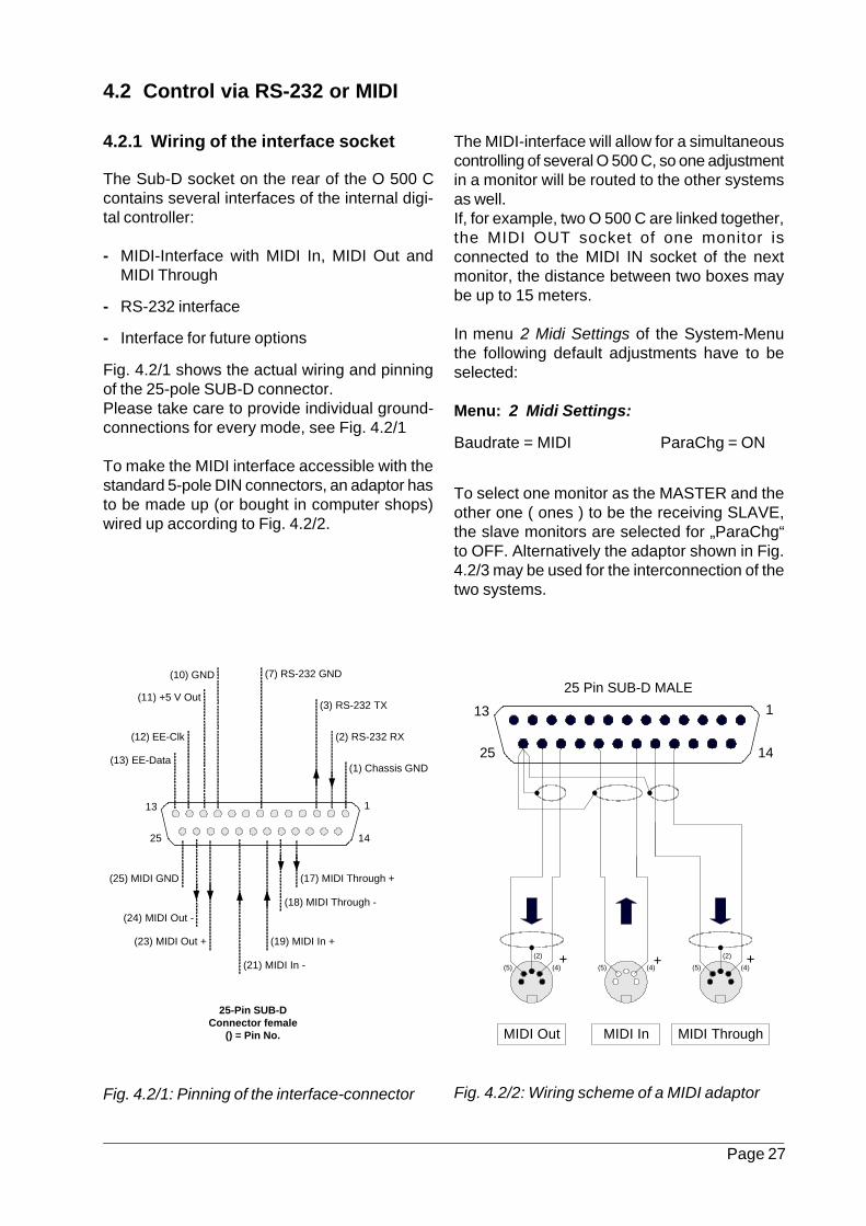
Fig. 4.2/1 shows the actual wiring and pinningof the 25-pole SUB-D connector.Please take care to provide individual ground-connections for every mode, see Fig. 4.2/1
To make the MIDI interface accessible with thestandard 5-pole DIN connectors, an adaptor hasto be made up (or bought in computer shops)wired up according to Fig. 4.2/2.
Fig. 4.2/1: Pinning of the interface-connector
The MIDI-interface will allow for a simultaneouscontrolling of several O 500 C, so one adjustmentin a monitor will be routed to the other systemsas well.If, for example, two O 500 C are linked together,the MIDI OUT socket of one monitor isconnected to the MIDI IN socket of the nextmonitor, the distance between two boxes maybe up to 15 meters.
In menu 2 Midi Settings of the System-Menuthe following default adjustments have to beselected:
Menu: 2 Midi Settings:
Baudrate = MIDI ParaChg = ON
To select one monitor as the MASTER and theother one ( ones ) to be the receiving SLAVE,the slave monitors are selected for „ParaChg“to OFF. Alternatively the adaptor shown in Fig.4.2/3 may be used for the interconnection of thetwo systems.
Fig. 4.2/2: Wiring scheme of a MIDI adaptor
4.2.1 Wiring of the interface socket
4.2 Control via RS-232 or MIDI
113
1425
(2) RS-232 RX
(1) Chassis GND
(3) RS-232 TX
(7) RS-232 GND(10) GND
(11) +5 V Out
(12) EE-Clk
(13) EE-Data
(25) MIDI GND
(24) MIDI Out -
(21) MIDI In -
(18) MIDI Through -
25-Pin SUB-DConnector female
() = Pin No.
(23) MIDI Out + (19) MIDI In +
(17) MIDI Through +
(4)(5)
113
1425
MIDI In MIDI ThroughMIDI Out
+ ++(5)(5) (4) (4)
(2) (2)
25 Pin SUB-D MALE
Page 28
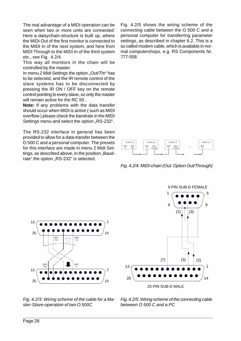
The real advantage of a MIDI operation can beseen when two or more units are connected:Here a daisychain-structure is built up, wherethe MIDI Out of the first monitor is connected tothe MIDI In of the next system, and here fromMIDI Through to the MIDI In of the third systemetc., see Fig. 4.2/4.This way all monitors in the chain will becontrolled by the master.In menu 2 Midi Settings the option „Out/Thr“ hasto be selected, and the IR remote control of theslave systems has to be disconnected bypressing the IR ON / OFF key on the remotecontrol pointing to every slave, so only the masterwill remain active for the RC 55 .Note: If any problems with the data transfershould occur when MIDI is active ( such as MIDIoverflow ) please check the bandrate in the MIDISettings menu and select the option „RS-232“.
The RS-232 interface in general has beenprovided to allow for a data-transfer between theO 500 C and a personal computer. The presetsfor this interface are made in menu 2 Midi Set-tings, as described above, in the position „Baud-rate“ the option „RS-232“ is selected.
Fig. 4.2/3: Wiring scheme of the cable for a Ma-ster-Slave-operation of two O 500C
Fig. 4.2/5 shows the wiring scheme of theconnecting cable between the O 500 C and apersonal computer for transferring parametersettings, as described in chapter 6.2. This is aso called modem cable, which is available in nor-mal computershops, e.g. RS Components Nr.777-558.
Fig. 4.2/5: Wiring scheme of the connecting cablebetween O 500 C and a PC
Fig. 4.2/4: MIDI-chain (Out: Option Out/Through)
113
1425
113
1425
(MIDIOut)
MIDIIn
(MIDIIn)
MIDIOut
113
1425
(7) (2)(3)
1 5
6 9
(2) (3)
25 PIN SUB-D MALE
9 PIN SUB-D FEMALE
O 500 C #1 O 500 C #nO 500 C #3O 500 C #2
...MIDIIn
MIDIIn
MIDIIn
MIDIIn
MIDIOut
MIDIThrough
MIDIThrough
Page 29
4.2.2 Midi-Commands
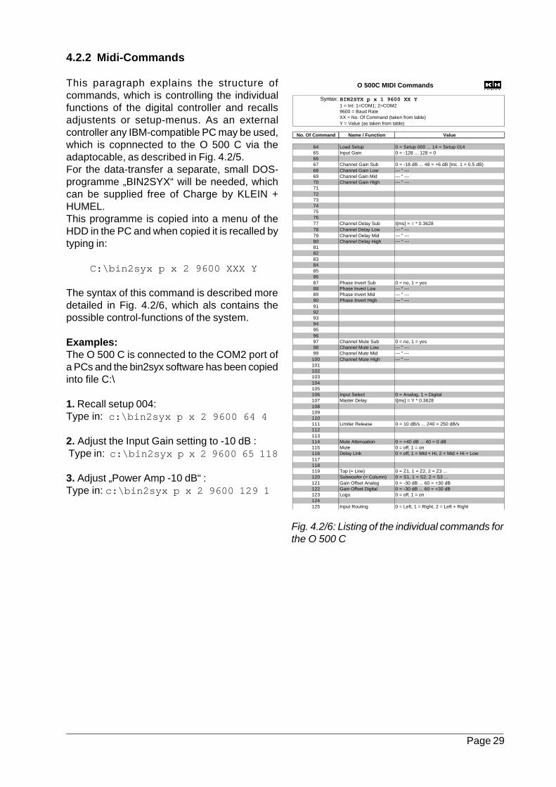
This paragraph explains the structure ofcommands, which is controlling the individualfunctions of the digital controller and recallsadjustents or setup-menus. As an externalcontroller any IBM-compatible PC may be used,which is copnnected to the O 500 C via theadaptocable, as described in Fig. 4.2/5.For the data-transfer a separate, small DOS-programme „BIN2SYX“ will be needed, whichcan be supplied free of Charge by KLEIN +HUMEL.This programme is copied into a menu of theHDD in the PC and when copied it is recalled bytyping in:
C:\bin2syx p x 2 9600 XXX Y
The syntax of this command is described moredetailed in Fig. 4.2/6, which als contains thepossible control-functions of the system.
Examples:The O 500 C is connected to the COM2 port ofa PCs and the bin2syx software has been copiedinto file C:\
1. Recall setup 004:Type in: c:\bin2syx p x 2 9600 64 4
2. Adjust the Input Gain setting to -10 dB : Type in: c:\bin2syx p x 2 9600 65 118
3. Adjust „Power Amp -10 dB“ :Type in: c:\bin2syx p x 2 9600 129 1
Fig. 4.2/6: Listing of the individual commands forthe O 500 C
Syntax: BIN2SYX p x 1 9600 XX Y1 = Int: 1=COM1; 2=COM29600 = Baud RateXX = No. Of Command (taken from table)Y = Value (as taken from table)
No. Of Command Name / Function Value
64 Load Setup 0 = Setup 000 ... 14 = Setup 01465 Input Gain 0 = -128 ... 128 = 06667 Channel Gain Sub 0 = -18 dB ... 48 = +6 dB [Inc. 1 = 0.5 dB)68 Channel Gain Low --- " ---69 Channel Gain Mid --- " ---70 Channel Gain High --- " ---71727374757677 Channel Delay Sub t[ms] = Y * 0.362878 Channel Delay Low --- " ---79 Channel Delay Mid --- " ---80 Channel Delay High --- " ---81828384858687 Phase Invert Sub 0 = no, 1 = yes88 Phase Invert Low --- " ---89 Phase Invert Mid --- " ---90 Phase Invert High --- " ---91929394959697 Channel Mute Sub 0 = no, 1 = yes98 Channel Mute Low --- " ---99 Channel Mute Mid --- " ---
100 Channel Mute High --- " ---101102103104105106 Input Select 0 = Analog, 1 = Digital107 Master Delay t[ms] = Y * 0.3628108109110111 Limiter Release 0 = 10 dB/s ... 240 = 250 dB/s112113114 Mute Attenuation 0 = +40 dB ... 40 = 0 dB115 Mute 0 = off, 1 = on116 Delay Link 0 = off, 1 = Mid + Hi, 2 = Mid + Hi + Low117118119 Top (= Line) 0 = Z1, 1 = Z2, 2 = Z3 ...120 Subwoofer (= Column) 0 = S1, 1 = S2, 2 = S3 ...121 Gain Offset Analog 0 = -30 dB ... 60 = +30 dB122 Gain Offset Digital 0 = -30 dB ... 60 = +30 dB123 Logo 0 = off, 1 = on124125 Input Routing 0 = Left, 1 = Right, 2 = Left + Right
O 500C MIDI Commands
Page 30
5.1 Room EQ
GeneralThe parameter settings of the O 500 C havebeen optimized by K + H in the way, that in anon-reflecting surrounding there will be a linerfrequency response at the system.Such a reflection-free surriunding will not bepossible under practical conditions- on thecontrary- room and positioning of the monitorswill lead to significant unlinearties in thefrequency-response.
How inlinearities of the frequeny-response aregenerated by the location in the room.Base ofthis acoustic reaction is the principle ofinterferences of soundwaves. In general, therewill be always two or more sound waves needed,which are generated from two sources with acertain distance to each other.two interfearing signals may to the double level(0°-phase shift) or a complete cancellation of afrequency (180°-phase shift). In between thesetwo figures all levels/phaseshifts are possible.
How to use the internal room-EQ FeatureThe O 500 C is offering three powerful functionsfor the compensation of unlinearities in thefrequency response, which were caused by themonitor’s location: The compensation throughindividually generated parameter setups (chapter 6.4), the fully parametric EQ ( chapter5.2) plus the comfortable local EQ-function, asdescribed below. All adjustments will be madein the menu 1 EQ Set of the EQ-menu. On thefollowing pages all options from this menu willbe introduced, including some typical examples.
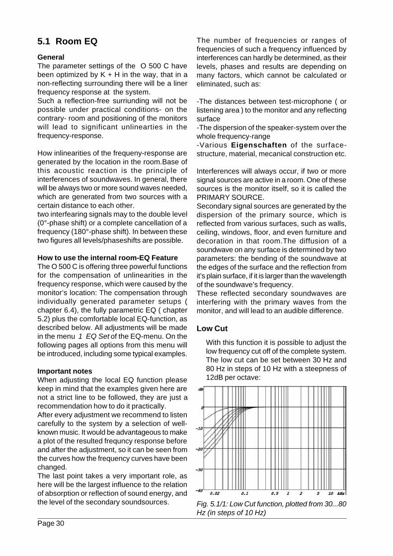
Important notesWhen adjusting the local EQ function pleasekeep in mind that the examples given here arenot a strict line to be followed, they are just arecommendation how to do it practically.After every adjustment we recommend to listencarefully to the system by a selection of well-known music. It would be advantageous to makea plot of the resulted frequncy response beforeand after the adjustment, so it can be seen fromthe curves how the frequency curves have beenchanged.The last point takes a very important role, ashere will be the largest influence to the relationof absorption or reflection of sound energy, andthe level of the secondary soundsources. Fig. 5.1/1: Low Cut function, plotted from 30...80
Hz (in steps of 10 Hz)
The number of frequencies or ranges offrequencies of such a frequency influenced byinterferences can hardly be determined, as theirlevels, phases and results are depending onmany factors, which cannot be calculated oreliminated, such as:
-The distances between test-microphone ( orlistening area ) to the monitor and any reflectingsurface-The dispersion of the speaker-system over thewhole frequency-range-Various Eigenschaften of the surface-structure, material, mecanical construction etc.
Interferences will always occur, if two or moresignal sources are active in a room. One of thesesources is the monitor itself, so it is called thePRIMARY SOURCE.Secondary signal sources are generated by thedispersion of the primary source, which isreflected from various surfaces, such as walls,ceiling, windows, floor, and even furniture anddecoration in that room.The diffusion of asoundwave on any surface is determined by twoparameters: the bending of the soundwave atthe edges of the surface and the reflection fromit’s plain surface, if it is larger than the wavelengthof the soundwave’s frequency.These reflected secondary soundwaves areinterfering with the primary waves from themonitor, and will lead to an audible difference.
Low Cut
With this function it is possible to adjust thelow frequency cut off of the complete system.The low cut can be set between 30 Hz and80 Hz in steps of 10 Hz with a steepness of12dB per octave:
Page 31
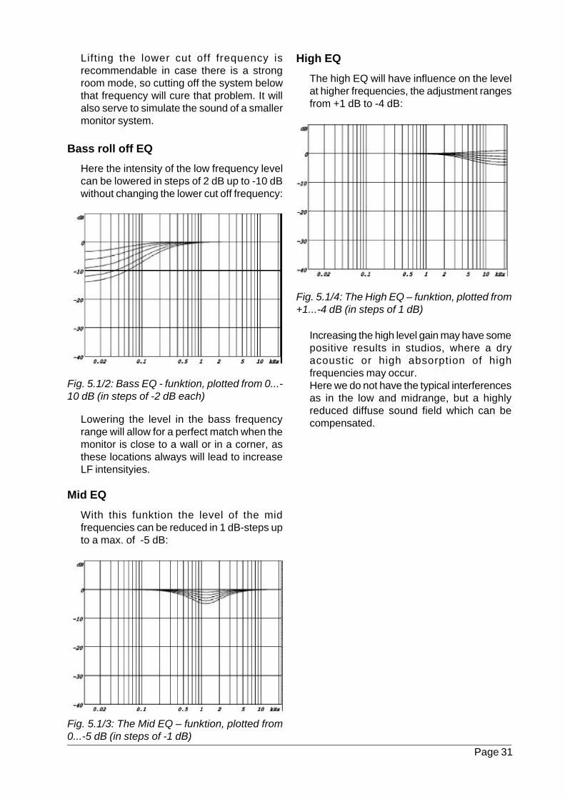
Bass roll off EQ
Here the intensity of the low frequency levelcan be lowered in steps of 2 dB up to -10 dBwithout changing the lower cut off frequency:
High EQ
The high EQ will have influence on the levelat higher frequencies, the adjustment rangesfrom +1 dB to -4 dB:
Lifting the lower cut off frequency isrecommendable in case there is a strongroom mode, so cutting off the system belowthat frequency will cure that problem. It willalso serve to simulate the sound of a smallermonitor system.
Fig. 5.1/2: Bass EQ - funktion, plotted from 0...-10 dB (in steps of -2 dB each)
Fig. 5.1/3: The Mid EQ – funktion, plotted from0...-5 dB (in steps of -1 dB)
Fig. 5.1/4: The High EQ – funktion, plotted from+1...-4 dB (in steps of 1 dB)
Lowering the level in the bass frequencyrange will allow for a perfect match when themonitor is close to a wall or in a corner, asthese locations always will lead to increaseLF intensityies.
Mid EQ
With this funktion the level of the midfrequencies can be reduced in 1 dB-steps upto a max. of -5 dB:
Increasing the high level gain may have somepositive results in studios, where a dryacoustic or high absorption of highfrequencies may occur.Here we do not have the typical interferencesas in the low and midrange, but a highlyreduced diffuse sound field which can becompensated.
Page 32
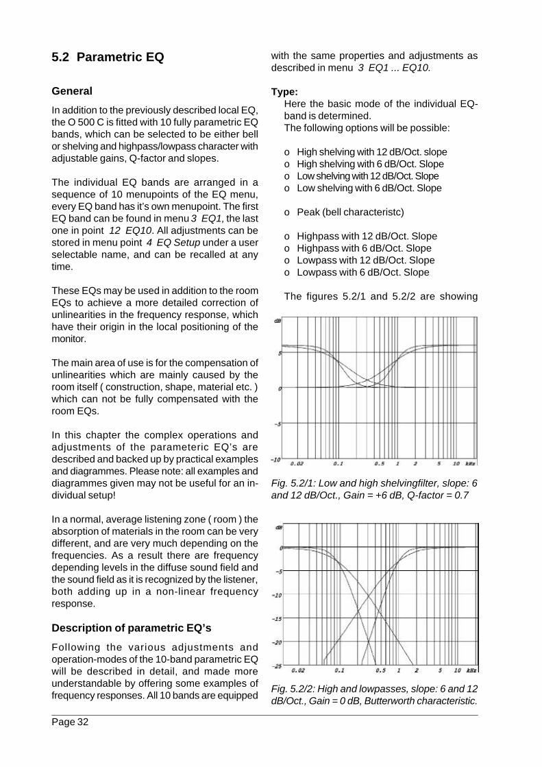
5.2 Parametric EQ
General
In addition to the previously described local EQ,the O 500 C is fitted with 10 fully parametric EQbands, which can be selected to be either bellor shelving and highpass/lowpass character withadjustable gains, Q-factor and slopes.
The individual EQ bands are arranged in asequence of 10 menupoints of the EQ menu,every EQ band has it’s own menupoint. The firstEQ band can be found in menu 3 EQ1, the lastone in point 12 EQ10. All adjustments can bestored in menu point 4 EQ Setup under a userselectable name, and can be recalled at anytime.
These EQs may be used in addition to the roomEQs to achieve a more detailed correction ofunlinearities in the frequency response, whichhave their origin in the local positioning of themonitor.
The main area of use is for the compensation ofunlinearities which are mainly caused by theroom itself ( construction, shape, material etc. )which can not be fully compensated with theroom EQs.
In this chapter the complex operations andadjustments of the parameteric EQ’s aredescribed and backed up by practical examplesand diagrammes. Please note: all examples anddiagrammes given may not be useful for an in-dividual setup!
In a normal, average listening zone ( room ) theabsorption of materials in the room can be verydifferent, and are very much depending on thefrequencies. As a result there are frequencydepending levels in the diffuse sound field andthe sound field as it is recognized by the listener,both adding up in a non-linear frequencyresponse.
Description of parametric EQ’s
Following the various adjustments andoperation-modes of the 10-band parametric EQwill be described in detail, and made moreunderstandable by offering some examples offrequency responses. All 10 bands are equipped
with the same properties and adjustments asdescribed in menu 3 EQ1 ... EQ10.
Type:Here the basic mode of the individual EQ-band is determined.The following options will be possible:
o High shelving with 12 dB/Oct. slopeo High shelving with 6 dB/Oct. Slopeo Low shelving with 12 dB/Oct. Slopeo Low shelving with 6 dB/Oct. Slope
o Peak (bell characteristc)
o Highpass with 12 dB/Oct. Slopeo Highpass with 6 dB/Oct. Slopeo Lowpass with 12 dB/Oct. Slopeo Lowpass with 6 dB/Oct. Slope
The figures 5.2/1 and 5.2/2 are showing
Fig. 5.2/1: Low and high shelvingfilter, slope: 6and 12 dB/Oct., Gain = +6 dB, Q-factor = 0.7
Fig. 5.2/2: High and lowpasses, slope: 6 and 12dB/Oct., Gain = 0 dB, Butterworth characteristic.
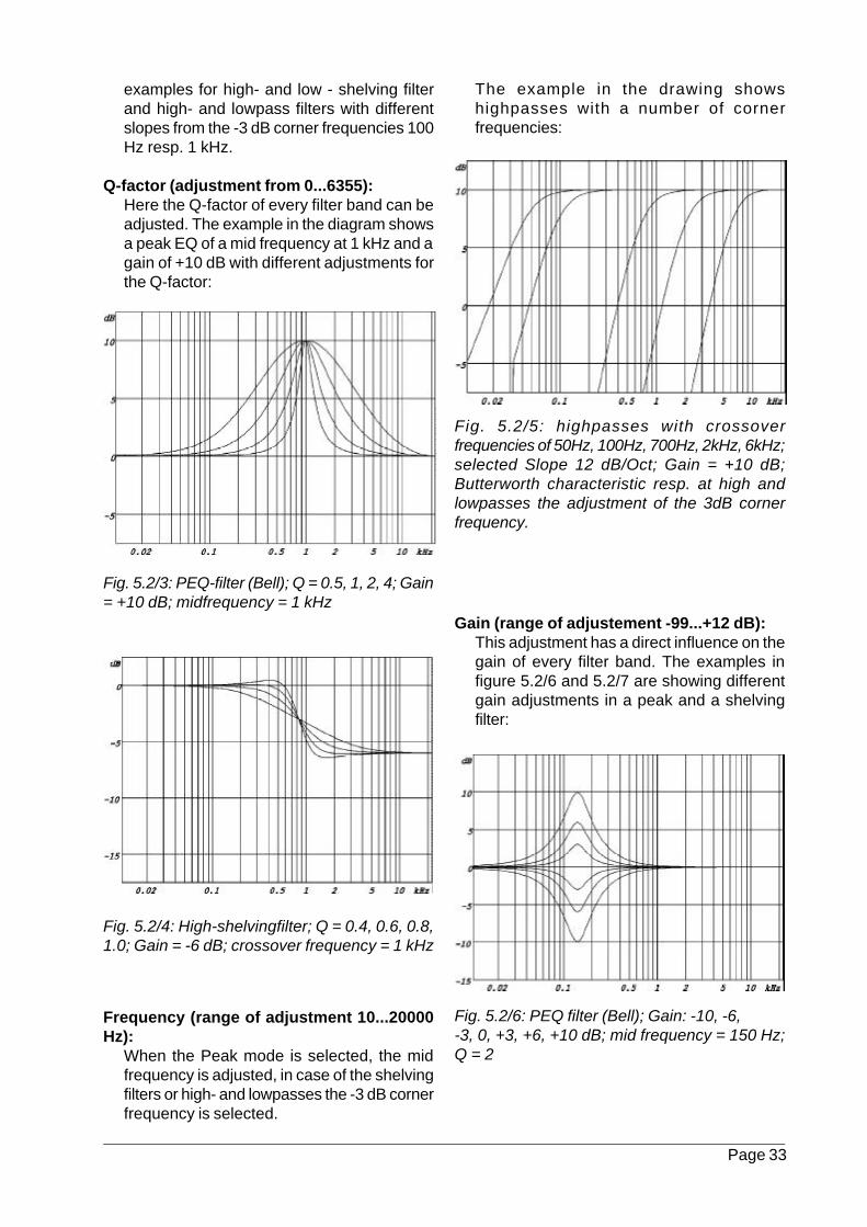
Page 33
examples for high- and low - shelving filterand high- and lowpass filters with differentslopes from the -3 dB corner frequencies 100Hz resp. 1 kHz.
Q-factor (adjustment from 0...6355):Here the Q-factor of every filter band can beadjusted. The example in the diagram showsa peak EQ of a mid frequency at 1 kHz and again of +10 dB with different adjustments forthe Q-factor:
The example in the drawing showshighpasses with a number of cornerfrequencies:
Fig. 5.2/3: PEQ-filter (Bell); Q = 0.5, 1, 2, 4; Gain= +10 dB; midfrequency = 1 kHz
Fig. 5.2/4: High-shelvingfilter; Q = 0.4, 0.6, 0.8,1.0; Gain = -6 dB; crossover frequency = 1 kHz
Frequency (range of adjustment 10...20000Hz):
When the Peak mode is selected, the midfrequency is adjusted, in case of the shelvingfilters or high- and lowpasses the -3 dB cornerfrequency is selected.
Fig. 5.2/5: highpasses with crossoverfrequencies of 50Hz, 100Hz, 700Hz, 2kHz, 6kHz;selected Slope 12 dB/Oct; Gain = +10 dB;Butterworth characteristic resp. at high andlowpasses the adjustment of the 3dB cornerfrequency.
Gain (range of adjustement -99...+12 dB):This adjustment has a direct influence on thegain of every filter band. The examples infigure 5.2/6 and 5.2/7 are showing differentgain adjustments in a peak and a shelvingfilter:
Fig. 5.2/6: PEQ filter (Bell); Gain: -10, -6,-3, 0, +3, +6, +10 dB; mid frequency = 150 Hz;Q = 2
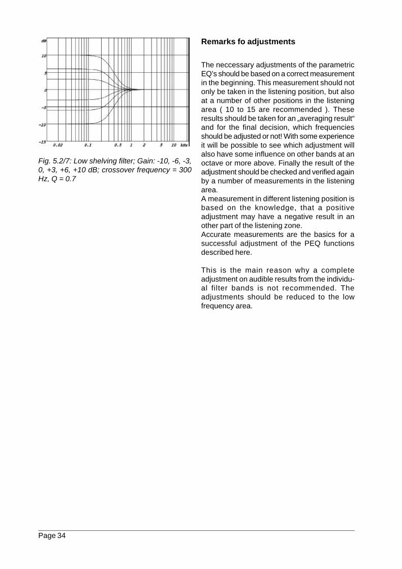
Page 34
Fig. 5.2/7: Low shelving filter; Gain: -10, -6, -3,0, +3, +6, +10 dB; crossover frequency = 300Hz, Q = 0.7
Remarks fo adjustments
The neccessary adjustments of the parametricEQ’s should be based on a correct measurementin the beginning. This measurement should notonly be taken in the listening position, but alsoat a number of other positions in the listeningarea ( 10 to 15 are recommended ). Theseresults should be taken for an „averaging result“and for the final decision, which frequenciesshould be adjusted or not! With some experienceit will be possible to see which adjustment willalso have some influence on other bands at anoctave or more above. Finally the result of theadjustment should be checked and verified againby a number of measurements in the listeningarea.A measurement in different listening position isbased on the knowledge, that a positiveadjustment may have a negative result in another part of the listening zone.Accurate measurements are the basics for asuccessful adjustment of the PEQ functionsdescribed here.
This is the main reason why a completeadjustment on audible results from the individu-al filter bands is not recommended. Theadjustments should be reduced to the lowfrequency area.
Page 35
6 Calculation of Parameters
GeneralThe loudspeaker parameter setup contains alladjustments and informations of the internal di-gital controller to obtain the desired frequencyand phase response plus all limiter andprotection functions for the O 500 C.
For every O 500 C an individual set ofparameters will be set at the factory. This set ofparameters contains far more information as itis the case in any other digital or analogcontrolled monitor on the market today.Normally these functions are reduced to theselection of crossover frequencies and gains inevery amplifier stage, an EQ of the frequencyresponse for a better linearisation and a setupfor the limiters.The O 500 C is supplied with a complexequalisation for every driver system. The EQis not only reduced to the frequency andamplitude of the whole system, but alsoincludes the adjustment of the phaseresponse down to 40 Hz!
The adjustments contained in loudspeakerparameter setup can be looked at in threegroups:
1. Filter coefficients of the FIR filterbandpasses (FIR = Finite Impulse Response)2. Limiter parameters3. Output scaling factors
The adjustments within a loudspeaker parametersetup can not be influenced by the user, as anychange (if possible) would result in a loss ofquality of the transmission datas of the monitor.In the FlashROM-memory of the built-in digitalcontroller a number of parameter settings arestored as a standard. Each of them can containdifferent acoustic results.A change between the stored parameter settingsis made in the menu „Monitor / Subwoofer“ ofthe MAIN menu and can be made while usingthe monitor (see chapter 3.2, menu step 8).
Loading of loudspeaker parameter setupsNote: New loudspeaker parameter setups canonly be downloaded into the system by erasingthe old, existing files. It is not possible to addnew settigs to the list!
- The serial interface (RS-232) socket of a PCis linked to the serial connector of theO 500 C by using a standard interface cable,as described in chapter 4.2.
- Switch ON the O 500 C by the POWERSWITCH and check if in menu2 Midi Settings of the System-Menu„Baudrate“ the option „RS232“ is activated,see chapter 3.
- Now copy all new data files supplied by K+H(on a FDD, by E-Mail or on a CD-R) into a fileof the HDD of the PC. Then the PC has to berebooted and started in the DOS-mode.
- After changing into the directory containingthe files just type in „TXMATRX“ to start thedata transfer
- Wait until the display will show „Input Gain“,now the transfer is completed.
- Switch OFF the O 500 C and - after a fewseconds - ON again, wait for the notice:„Wrong Filter Setup“ and press ENTER
- Now disconnect the O 500 C from the PC.
Room specific parameter settingsTo compensate for room and positioning specificunlinearities in the frequency response, italternatively is possible to make up a roomspecific loudspeaker parameter setup instead ofusing the Room- or PEQ sections described inchapter 5.1 and 5.2. This will contain theadjustments of the EQ’s but without thecharacteristic influence on the phase response.In order to do this it is neccessary to make acomplete measurement of the installed monitorsystem in the relevant room or studio by using aspecial measuring setup which is capable ofcalculating the new filtersetups. In addition to thisit will be possible to also include a „individualcoloration“ of the response according to personalpreferences.
The measurements needed for this setup, plusthe neccessary calculations and corrections canbe carried out at extra cost by K+H or by asubcontractor.
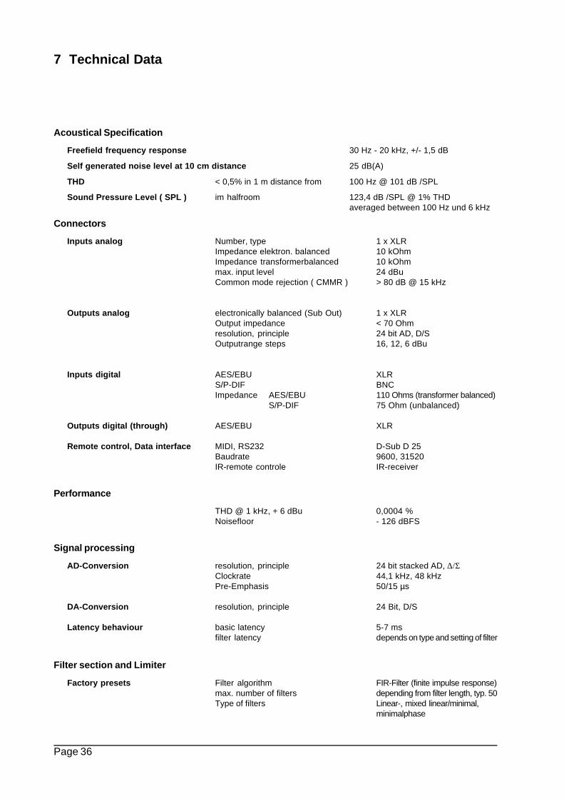
Page 36
7 Technical Data
Acoustical Specification
Freefield frequency response 30 Hz - 20 kHz, +/- 1,5 dB
Self generated noise level at 10 cm distance 25 dB(A)
THD < 0,5% in 1 m distance from 100 Hz @ 101 dB /SPL
Sound Pressure Level ( SPL ) im halfroom 123,4 dB /SPL @ 1% THDaveraged between 100 Hz und 6 kHz
Connectors
Inputs analog Number, type 1 x XLR Impedance elektron. balanced 10 kOhm Impedance transformerbalanced 10 kOhm max. input level 24 dBu Common mode rejection ( CMMR ) > 80 dB @ 15 kHz
Outputs analog electronically balanced (Sub Out) 1 x XLR Output impedance < 70 Ohm
resolution, principle 24 bit AD, D/S Outputrange steps 16, 12, 6 dBu
Inputs digital AES/EBU XLRS/P-DIF BNC
Impedance AES/EBU 110 Ohms (transformer balanced)S/P-DIF 75 Ohm (unbalanced)
Outputs digital (through) AES/EBU XLR
Remote control, Data interface MIDI, RS232 D-Sub D 25 Baudrate 9600, 31520 IR-remote controle IR-receiver
Performance
THD @ 1 kHz, + 6 dBu 0,0004 % Noisefloor - 126 dBFS
Signal processing
AD-Conversion resolution, principle 24 bit stacked AD, ∆/Σ Clockrate 44,1 kHz, 48 kHz Pre-Emphasis 50/15 µs
DA-Conversion resolution, principle 24 Bit, D/S
Latency behaviour basic latency 5-7 ms filter latency depends on type and setting of filter
Filter section and Limiter
Factory presets Filter algorithm FIR-Filter (finite impulse response)max. number of filters depending from filter length, typ. 50Type of filters Linear-, mixed linear/minimal,
minimalphase
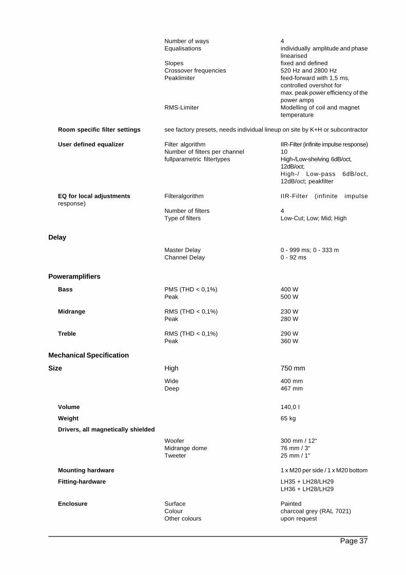
Page 37
Number of ways 4 Equalisations individually amplitude and phase
linearised Slopes fixed and defined
Crossover frequencies 520 Hz and 2800 Hz Peaklimiter feed-forward with 1,5 ms,
controlled overshot formax. peak power efficiency of thepower amps
RMS-Limiter Modelling of coil and magnettemperature
Room specific filter settings see factory presets, needs individual lineup on site by K+H or subcontractor
User defined equalizer Filter algorithm IIR-Filter (infinite impulse response) Number of filters per channel 10 fullparametric filtertypes High-/Low-shelving 6dB/oct,
12dB/oct;High-/ Low-pass 6dB/oct,12dB/oct; peakfilter
EQ for local adjustments Filteralgorithm IIR-Filter (infinite impulseresponse) Number of filters 4 Type of filters Low-Cut; Low; Mid; High
Delay
Master Delay 0 - 999 ms; 0 - 333 m Channel Delay 0 - 92 ms
Poweramplifiers
Bass PMS (THD < 0,1%) 400 WPeak 500 W
Midrange RMS (THD < 0,1%) 230 WPeak 280 W
Treble RMS (THD < 0,1%) 290 WPeak 360 W
Mechanical Specification
Size High 750 mm
Wide 400 mm Deep 467 mm
Volume 140,0 l
Weight 65 kg
Drivers, all magnetically shielded
Woofer 300 mm / 12“Midrange dome 76 mm / 3“Tweeter 25 mm / 1“
Mounting hardware 1 x M20 per side / 1 x M20 bottom
Fitting-hardware LH35 + LH28/LH29LH36 + LH28/LH29
Enclosure Surface PaintedColour charcoal grey (RAL 7021)Other colours upon request