Embed Size (px)
Citation preview
1
Montage- und Bedienungsanleitung (S. 2)Mounting instruction an operating manual (p. 38)
Funk-Rauchmelder:Radio-controlled smoke detector:HM-Sec-SD
geprüft nach DIN EN14604:2005tested by
G209094
2
1. Ausgabe Deutsch 05/2009Dokumentation © 2009 eQ-3 Ltd., Hong KongAlle Rechte vorbehalten. Ohne schriftliche Zustim-mung des Herausgebers darf dieses Handbuch auch nicht auszugsweise in irgendeiner Form re-produziert werden oder unter Verwendung elektro-nischer, mechanischer oder chemischer Verfahren vervielfältigt oder verarbeitet werden.Es ist möglich, dass das vorliegende Handbuch noch drucktechnische Mängel oder Druckfehler aufweist. Die Angaben in diesem Handbuch wer-den jedoch regelmäßig überprüft und Korrekturen in der nächsten Ausgabe vorgenommen. Für Fehler technischer oder drucktechnischer Art und ihre Folgen übernehmen wir keine Haftung.Alle Warenzeichen und Schutzrechte werden anerkannt.Printed in Hong KongÄnderungen im Sinne des technischen Fortschritts können ohne Vorankündigung vorgenommen werden.
83454 / V 1.1
3
Inhaltsverzeichnis
1 Hinweise zu dieser Anleitung. . . . . . . . . . . . . 52 Gefahrenhinweise . . . . . . . . . . . . . . . . . . . . . . 63 Allgemeines und Funktion . . . . . . . . . . . . . . . 63.1 Bestimmungsgemäßer Gebrauch . . . . . . . . . 73.2 Sicherheits- und Wartungshinweise . . . . . . . 84 Allgemeine Systeminformation zu HomeMatic. 105 Allgemeine Hinweise zum Funkbetrieb . . . . . .106 Installation . . . . . . . . . . . . . . . . . . . . . . . . . . . . . .116.1 Installationsorte und -hinweise . . . . . . . . . . . . .116.2 Montage des Melders. . . . . . . . . . . . . . . . . . . . .157 Inbetriebnahme . . . . . . . . . . . . . . . . . . . . . . . . . .177.1 Batterien einlegen . . . . . . . . . . . . . . . . . . . . . . . .177.2 Übersicht der Bedienung am Funkmodul . . . .187.3 Rauchmelder in den Sockel einrasten . . . . . . .188 Anlernen . . . . . . . . . . . . . . . . . . . . . . . . . . . . . . . .198.1 Funk-Rauchmelder aneinander anlernen. . . . .198.2 Funk-Rauchmelder an andere HomeMatic-
Komponenten anlernen . . . . . . . . . . . . . . . . . . .219 Funktionskontrolle und Betrieb . . . . . . . . . . . . .229.1 Funktionskontrolle Rauchmelder . . . . . . . . . . .229.2 Periodische Überprüfung und Fehleranzeige .249.3 Funk-Vernetzung testen . . . . . . . . . . . . . . . . . . .2510 Drahtgebundene Vernetzung mehrerer
Rauchmelder . . . . . . . . . . . . . . . . . . . . . . . . . . . .26
4
11 Auslieferungszustand wiederherstellen. . . . . .3012 Batteriewechsel. . . . . . . . . . . . . . . . . . . . . . . . . .30 13 Zusätzliche Hinweise – bitte beachten! . . . . . .3214 Technische Daten . . . . . . . . . . . . . . . . . . . . . . . .3415 Anhang . . . . . . . . . . . . . . . . . . . . . . . . . . . . . . . . .35
5
1 Hinweise zu dieser Anleitung
Lesen Sie diese Anleitung sorgfältig, bevor Sie Ihre HomeMatic Komponenten in Betrieb nehmen. Bewahren Sie die Anleitung zum späteren Nach-schlagen auf! Wenn Sie das Gerät anderen Personen zur Nutzung überlassen, übergeben Sie auch diese Bedienungsanleitung.
Benutzte Symbole:Achtung! Hier wird auf eine Gefahr hinge-wiesen.
Hinweis. Dieser Abschnitt enthält zusätz-liche wichtige Informationen!
6
2 Gefahrenhinweise
Öffnen Sie das Gerät nicht, es enthält keine durch den Anwender zu wartenden Teile.
Im Fehlerfall schicken Sie das Gerät an unseren Service. Betreiben Sie das Gerät nur in Innenräumen und vermeiden Sie den Einfluss von Feuchtigkeit, Staub, sowie Sonnen- oder andere Wärmebestrah-lung.
3 Allgemeines und Funktion
Dieser Rauchmelder überwacht einen Raum auf Basis des photoelektrischen Streulichtprinzips auf Rauchentwicklung. Hierdurch ist ein beginnender Brand frühzeitig erkennbar, um eine rechtzeitige Warnung vor den gefährlichen Rauchgasen erfol-gen zu lassen. Er gibt durch eine integrierte Sirene sowie eine parallel arbeitende rote Warn-LED und eine weiße LED (zur Notbeleuchtung bei Stromausfall) Alarm. Der HM-Sec-SD meldet einen Rauchalarm per Funk gleichzeitig an alle in der Funkreichweite
7
befindlichen Funk-Rauchmelder des gleichen Typs. So kann auf einen räumlich entfernten Brand, etwa in einem anderen Stockwerk des Hauses, noch rechtzeitig reagiert werden.Der Rauchmelder ist mit anderen Funk-Rauchmel-dern dieses Typs zu einem System mit beliebig vielen Meldern ausbaubar.Der Funk-Rauchmelder HM-Sec-SD kann zusätz-lich an die HomeMatic-Zentrale angelernt werden.Zusätzlich ist über eine Leitungsverbindung zwischen mehreren Rauchmeldern der RM 100-Reihe und einem HM-Sec-SD die Weitergabe eines Rauchalarms möglich. So kann man auch Räume überwachen, die funktechnisch schwierige Bedin-gungen aufweisen.Um Überschneidungen mit anderen Funkdiensten im 868-MHz-Band zu vermeiden, arbeitet das System mit individuellen Funkadressen und ist so sicher vor Fehlalarmen durch andere Funksender in diesem Frequenzbereich.
3.1 Bestimmungsgemäßer Gebrauch
Der Funk-Rauchmelder HM-Sec-SD ist für den Ein-satz im Verbund mit anderen Funk-Rauchmeldern HM-Sec-SD bestimmt.
8
Der Funk-Rauchmelder darf nicht in Umgebungen eingesetzt werden, in denen es durch die Übertra-gung von Funksignalen zur Störung von Geräten kommen kann, z.B. in medizinischen Einrichtungen mit lebenserhaltenden Systemen oder ähnlichen Umgebungen.Zur ordnungsgemäßen Funktion sind die in dieser Anleitung gegebenen Montagehinweise zu beach-ten.Das Gerät darf keinesfalls modifiziert werden.Für die Folgen nicht bestimmungsgemäßen Ge-brauchs übernimmt der Hersteller keine Haftung, sämtliche Garantieansprüche entfallen.
3.2 Sicherheits- und Wartungshinweise
- Bei Zweifel über die Arbeitsweise, die Sicherheit oder den Anschluss des Gerätes eine Fachkraft oder unseren Service kontaktieren.
- Das Gerät nicht verwenden, wenn es von außen erkennbare Schäden, z. B. am Gehäuse, an den Bedienelementen oder den Anschlusslei-tungen bzw. eine Funktionsstörung aufweist. Im Zweifelsfall das Gerät von einer Fachkraft oder unserem Service prüfen lassen.
- Öffnen Sie das Gerät außer zum Batteriewech-
9
sel, zur Verkabelung und Codierung nicht, es enthält keine durch Sie zu wartenden Teile. Im Fehlerfall schicken Sie ein defektes Gerät an unseren Service.
- Betreiben Sie das Gerät nur in Innenräumen und vermeiden Sie den Einfluss von Feuchtigkeit, Staub sowie unmittelbare Sonnenbestrahlung.
- Das System darf nicht im Zugriffsbereich von Kindern aufbewahrt/betrieben werden. Es ist kein Spielzeug!
- Verpackungsmaterial nicht achtlos liegen lassen. Plas tikfolien/-tüten, Styroporteile etc. könnten für Kinder zu einem gefährlichen Spiel-zeug werden.
- Die Wartung erfolgt alle 6 Monate durch Abwi-schen des Gehäuses mit einem leicht ange-feuchteten Tuch.
- Der Rauchmelder darf nicht mit Farbe bestri-chen oder mit Tapete überklebt werden!
- Einmal im Monat ist durch Betätigen der Prüf-taste ein Funktionstest durchzuführen.
10
4 Allgemeine Systeminformation zu HomeMatic
Dieses Gerät ist Teil des HomeMatic Haussteuer-systems.Alle Geräte werden mit einer Standardkonfigura-tion ausgeliefert. Darüber hinaus ist die Funktion des Gerätes über ein Programmiergerät und Software konfigurierbar. Welcher weitergehende Funktionsumfang sich damit ergibt, und welche Zusatzfunktionen sich im HomeMatic System im Zusammenspiel mit weiteren Komponenten ergeben, entnehmen Sie bitte der gesonderten Konfigurationsanleitung oder dem HomeMatic Systemhandbuch. Alle technischen Dokumente und Updates finden Sie stets aktuell unter www.HomeMatic.com.
5 Allgemeine Hinweise zum Funkbetrieb
Die Funk-Übertragung wird auf einem nicht exklusiven Übertragungsweg realisiert, weshalb Störungen nicht ausgeschlossen werden können.Weitere Störeinflüsse können hervorgerufen wer-
11
den durch Schaltvorgänge, Elektromotoren oder defekte Elektrogeräte.
Die Reichweite in Gebäuden kann stark von der im Freifeld abweichen. Außer der
Sendeleistung und den Empfangseigenschaften der Empfänger spielen Umwelteinflüsse wie Luft-feuchtigkeit neben baulichen Gegebenheiten vor Ort eine wichtige Rolle.
Hiermit erklärt die eQ-3 Entwicklung GmbH, dass sich dieses Gerät in Übereinstimmung mit den grundlegenden Anforderungen und den anderen relevanten Vorschriften der Richtlinie 1999/5/EG befindet.Die vollständige Konformitätserklärung finden Sie unter www.HomeMatic.com.
6 Installation
6.1 Installationsorte und -hinweise
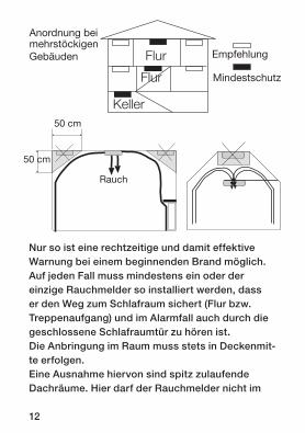
Grundsätzlich empfiehlt es sich, mehrere Rauch-melder im Gebäude bzw. in der Wohnung zu instal-lieren. Auf jeden Fall sollte bei mehrstöckigen Ge-bäuden ein Rauchmelder je Etage installiert sein.
12
Nur so ist eine rechtzeitige und damit effektive Warnung bei einem beginnenden Brand möglich.Auf jeden Fall muss mindestens ein oder der einzige Rauchmelder so installiert werden, dass er den Weg zum Schlafraum sichert (Flur bzw. Treppenaufgang) und im Alarmfall auch durch die geschlossene Schlafraumtür zu hören ist. Die Anbringung im Raum muss stets in Deckenmit-te erfolgen.Eine Ausnahme hiervon sind spitz zulaufende Dachräume. Hier darf der Rauchmelder nicht im
Flur
Flur
Keller
Flur
Flur
Keller
Flur
Flur
Keller
Anordnung bei mehrstöckigen Gebäuden Empfehlung
Mindestschutz
50 cm
50 cm
Rauch
13
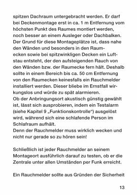
spitzen Dachraum untergebracht werden. Er darf bei Deckenmon tage erst in ca. 1 m Entfernung vom höchsten Punkt des Raumes montiert werden, noch besser an einem Ausleger oder Dachbalken.Der Grund für diese Montageplätze ist, dass nahe den Wänden und besonders in den Raum- ecken sowie bei spitzwinkligen Decken ein Luft-stau entsteht, der den aufsteigenden Rauch von den Wänden bzw. der Raumecke fern hält. Deshalb sollte in einem Bereich bis ca. 50 cm Entfernung von den Raumecken keinesfalls ein Rauchmelder installiert werden. Dieser bliebe im Ernstfall wir-kungslos und würde zu spät alarmieren.Ob der Anbringungsort akustisch günstig gewählt ist, lässt sich ausprobieren, indem ein Testalarm (siehe Kapitel 9 „Funktionskontrolle“) ausgelöst wird, während sich eine schlafende Person im Schlafraum aufhält. Denn der Rauchmelder muss wirklich wecken und nicht nur gerade so zu hören sein!
Schließlich ist jeder Rauchmelder an seinem Montageort ausführlich darauf zu testen, ob er die Zentrale unter allen Umständen per Funk erreicht.
Ein Rauchmelder sollte aus Gründen der Sicherheit
Mindestschutz
14
vor Fehlalarmen nicht in folgenden Räumen und Orten installiert werden:- Küche/Bad: starke Dämpfe in diesen Räumen
lösen Fehlalarm aus- Räume mit offenem Kamin: Gefahr von Fehlalar-
men- in unmittelbarer Nähe von Halogenlampen,
Trafos oder Halogenlampen-Seilsystemen sowie Leuchtstoff- und Energiesparlampen (Mindest-abstand 50 cm)
- Garagen: Fahrzeugabgase (Rauch) führen zu Fehlalarm
- staubige und schmutzige Räume: Messkammer verschmutzt schnell oder Auslösung von Fehl- alarmen
- in Fensternähe, in der Nähe von Ventilatoren, Lüftern und allen anderen Orten, wo Luft stark in Bewegung ist
- in der Nähe von Plätzen, wo geraucht wird; der Tabakrauch führt zu Fehlalarmen
- in der Nähe von massiven Stahlträgern, großen Metallflächen usw. Diese können die Abstrah-lung bzw. den Empfang des Funksignals erheb-lich behindern. Oft hilft hier ein Versetzen um nur wenige Zentimeter.
15
J4�
J3�
J2�
J1�
J6�
J5�
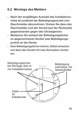
Befestigungslöcher bei Montage über ei-ner Installationsdose
Befestigung wahlweise mit Abstandhalter
Halter fürKabelbinder
6.2 Montage des Melders
- Nach der sorgfältigen Auswahl des Installations-ortes ist zunächst der Befestigungssockel vom Rauchmelder abzunehmen. Drehen Sie dazu den Rauchmelder und den Sockel (auf der Rückseite) gegeneinander gegen den Uhrzeigersinn.
- Markieren Sie anhand der Befestigungslöcher im abgenommenen Sockel zwei Befestigungs-punkte an der Decke.
- Zwei Befestigungslöcher bohren, Dübel einsetzen und dann den Sockel mit zwei Schrauben montie-ren.
16
- Alternativ, z. B. wenn Kabel zur Erweiterung unter dem Rauchmelder geführt werden sollen, ist der Rauchmelder auch unter Zwischenlegen der beiden mitgelieferten Abstandhalter montierbar. Die bei-den den Abstandhaltern entsprechenden Befesti-gungsöffnungen sind zur Montage zu nutzen (siehe Bild).
Weiterhin kann eine Befestigung über eine Standard-Installationsdose erfolgen. Dazu sind die beiden Installationsdosen-Befestigungslöcher zu nutzen.
- Vermeiden Sie eine Montage in der Nähe von massiven Stahlträgern, großen Metallflächen usw. Diese können die Abstrahlung bzw. den Empfang des Funksignals erheblich behindern. Oft hilft hier ein Versetzen um nur wenige Zentimeter.
17
7 Inbetriebnahme
7.1 Batterien einlegen
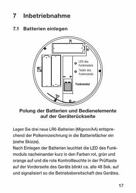
Legen Sie drei neue LR6-Batterien (Mignon/AA) entspre-chend der Polkennzeichnung in die Batteriefächer ein (siehe Skizze). Nach Einlegen der Batterien leuchtet die LED des Funk-moduls nacheinander kurz in den Farben rot, grün und orange auf und die rote Kontroll leuchte in der Prüftaste auf der Vorderseite des Geräts blinkt ca. alle 48 Sek. auf und signalisiert so die Betriebsbereitschaft des Gerätes.
Polung der Batterien und Bedienelemente auf der Geräterückseite
LED des Funkmoduls
Taster des Funkmoduls
Funkmodul
18
7.2 Übersicht der Bedienung am Funkmodul
Der akustische Signalgeber (Buzzer) des Funk-moduls bestätigt jeden kurzen und langen (etwa 5 Sekunden) Druck auf den Taster des Funkmoduls. Die LED signalisiert optisch den aktuellen Zustand.
kurzer Tastendruck: Anlern-/Konfigurationsmodus
- LED blinkt orange- kurzer Tastendruck: Anlern-/Konfigurations-
modus beenden- LED rot: Anlernen fehlgeschlagen- LED grün: Anlernen war erfolgreich
langer Tastendruck: Menü- LED blinkt rot- kurzer Tastendruck: Test der Funkvernetzung- langer Tastendruck: Zurücksetzen in den
Auslieferungszustand
7.3 Rauchmelder in den Sockel einrasten
Wenn keine Einstellungen am Funkmodul mehr erforderlich sind, kann der Rauchmelder in den
19
Sockel eingerastet werden. Rasten Sie den Rauch-melder durch Drehen im Uhrzeigersinn in den Sockel ein. Bei der richtigen Positionierung helfen die im Sockel und im Rauchmelder angebrachten roten Dreiecke.
Bitte beachten!Ohne eingelegte Batterien lässt sich der
Rauchmelder nicht auf den Sockel aufsetzen!
8 Anlernen
8.1 Funk-Rauchmelder aneinander anlernen
Zum Anlernen zweier Funk-Rauchmelder aneinan-der muss zunächst der Taster des Funkmoduls des einen Rauchmelders kurz gedrückt werden und anschließend innerhalb von 20 Sekunden der Ta-ster des Funkmoduls des anderen Rauchmelders kurz gedrückt werden. Die optische Signalisierung der LEDs der Funkmodule beider Rauchmelder muss mit grünem Leuchten für etwa 2 Sekunden enden.
20
Die Funk-Rauchmelder sollten während des Anlernvorgangs einen Abstand von mindestens einem Meter voneinander haben, weil die Funk-Signale bei zu geringem Abstand möglicherweise wegen zu hoher Intensität nicht korrekt empfangen werden können.Durch das Anlernen zweier Funk-Rauchmelder aneinander wird ein Funk-Netz gebildet. Der Rauchalarm eines Funk-Rauchmelders im Netz wird automatisch an allen Funk-Rauchmeldern im Netz signalisiert.Um einen neuen Funk-Rauchmelder in ein beste-hendes Funk-Netz einzubinden, genügt es, diesen an einen Funk-Rauchmelder aus dem bestehenden Funk-Netz anzulernen.Um einen Funk-Rauchmelder aus einem Funk-Netz zu entfernen muss dieser in den Auslieferungszu-stand zurückgesetzt werden. Anschließend kann er in ein anders Funk-Netz eingebunden werden, oder zusammen mit einem anderen Funk-Rauch-melder, der sich ebenfalls im Auslieferungszustand befindet, durch Anlernen an diesen ein neues Funk-Netz bilden.
21
8.2 Funk-Rauchmelder an andere HomeMatic-Komponenten anlernen
Ein Netz aus Funk-Rauchmeldern kann als Sensor für einen HomeMatic Aktor dienen. Dazu muss der Aktor (z. B. zum An-/Ausschalten einer Lampe) an einen Funk-Rauchmelder aus dem Netz angelernt werden. Zum Anlernen müssen beide zu ver-knüpfende Geräte in den Anlernmodus gebracht werden. Um den Funk-Rauchmelder in den Anlernmodus zu bringen, drücken Sie kurz auf den Taster des Funkmoduls. Die LED des Funkmoduls blinkt orange. Wenn kein Anlernen erfolgt, wird der Anlernmodus automatisch nach 20 Sekunden beendet.
Hinweis: Ist der Rauchmelder bereits an eine Zentrale angelernt und damit für
direktes Anlernen gesperrt, kann er zwar wie oben beschrieben in den Anlernmodus gebracht werden, es erfolgt jedoch kein Anlernen und die LED des Funkmoduls leuchtet für 2 Sekunden rot auf.In der Standardkonfiguration wird der Aktor vom Rauchmelder so konfiguriert, dass er bei einem Rauchalarm einschaltet und nach der zugehörigen Entwarnung wieder ausschaltet.
22
Alle Geräte werden mit einer Standardkonfigura- tion ausgeliefert. Welche Zusatzfunktionen sich im HomeMatic System im Zusammenspiel mit weiteren Komponenten ergeben, entnehmen Sie bitte dem HomeMatic Systemhandbuch.
9 Funktionskontrolle und Betrieb
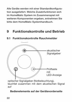
9.1 Funktionskontrolle Rauchmelder
J4�
J3�
J2�
J1�
J6�
J5�
akustischerSignalgeber
Prüftaste mit LED-Anzeige
optischer Signalgeber (Notbeleuchtung),leuchtet zusammen mit dem akustischen Signal auf
Bedienelemente auf der Gerätevorderseite
23
- Ist der Rauchmelder montiert, so sollte eine Funktionskontrolle durchgeführt werden.
- Dringt in die Rauchkammer Rauch ein, z. B. testweise Tabakrauch, so wird Alarm ausgelöst, solange sich Rauch in der Rauchkammer des Melders befindet.
Ein ausgelöster Alarm wird am Rauchmelder selbst durch ein akustisches und optisches Signal etwa im Sekundentakt signalisiert.- Ein Beenden des Alarms erfolgt automatisch
nach 48 Sekunden, und wenn der gesamte Testrauch aus der Rauchkammer entwichen ist.
- Durch Drücken der Prüftaste für ca. 2 Sek. bis zum Druckpunkt wird der akustische Alarm für ca. 10 Minuten abgeschaltet. Befindet sich da-bei noch Rauch in der Rauchkammer, blinkt die LED in der Prüftaste weiter. Befindet sich kein Rauch mehr in der Rauchkammer, kann mit der Prüftaste der Alarm komplett beendet werden.
- Wird an einem Funk-Rauchmelder Rauch-Alarm ausgelöst, beginnen alle weiteren Funk-Rauch-melder, die sich innerhalb der Funkreichweite dieses Melders befinden und an das Funknetz angelernt sind, ebenfalls mit der optischen und akustischen Signalisierung. (Funk-Übertragung verursacht Verzögerung von bis zu 16 Sekunden)
24
- Wird die Prüftaste am auslösenden Rauch-melder für ca. 2 Sek. gedrückt, erhalten alle Rauchmelder im System ein Funk-Signal zur Entwarnung. Die Signalisierung aller Rauchmel-der im Funk-Netz wird damit beendet. (Funk-Übertragung verursacht Verzögerung von bis zu 16 Sekunden)
- Um den auslösenden Melder, z. B. bei einem Fehlalarm, identifizieren zu können, blinkt dessen rote Kontroll-LED in der Prüftaste 10 Minuten weiter.
9.2 Periodische Überprüfung und Fehler-anzeige
Einmal monatlich ist die Funktion des Rauchmel-ders durch Drücken der Prüftaste bis zum Druck-punkt für ca. 2 Sek. zu überprüfen:- Ertönt das akustische Signal einmal und die
LED in der Prüftaste blinkt 10 mal, arbeitet der Rauchmelder korrekt.
- Beginnt nach dem Drücken der Taste nur die Leuchtdiode zu blinken, ist der Rauchmelder defekt und muss ausgetauscht werden.
- Erfolgt keinerlei Signalgabe, ist zuerst zu überprüfen, ob die Batterien polrichtig eingelegt
25
sind. Ist dies der Fall, sind die Batterien zu überprüfen sowie ggf. auszutauschen. Sind die Batterien in Ordnung, ist der Rauchmelder defekt und muss ausgetauscht werden.
9.3 Funk-Vernetzung testen
Die Zugehörigkeit eines Funk-Rauchmelders zu einem Funk-Netz kann überprüft werden, indem man den Rauchmelder ein Test-Funk-Signal sen-den lässt. Zum Erzeugen des Test-Funk-Signals muss der Taster des Funkmoduls zuerst für etwa 5 Sekunden gedrückt werden, bis die LED des Funkmoduls rot zu blinken beginnt. Anschließend muss der Taster einmal kurz gedrückt werden. Jetzt wird das Test-Funk-Signal gesendet.Auf dieses Signal reagieren alle Funk-Rauchmel-der, die dem Funk-Netz angehören, indem sie mit dem akustischen Signalgeber (Buzzer) des Funk-moduls 10 mal alle 8 Sekunden drei kurze Signale erzeugen.Die Test-Funk-Signale werden nur von Funkmo-dulen von Funk-Rauchmeldern ausgewertet. Sie werden von den Rauchmeldern selbst nicht weiter ausgewertet und auch nicht über die drahtgebun-dene Vernetzung (falls vorhanden) weitergeleitet.
26
Auch andere angelernte HomeMatic-Komponenten reagieren nicht auf die Funk-Test-Signale.Für einen Test aller Komponenten im System muss ein Rauchalarm (z. B. durch Zigarettenrauch) ausgelöst werden.
10 Drahtgebundene Vernetzung mehrerer Rauchmelder
Müssen ein oder mehrere Rauchmelder an einem Ort montiert werden, der, etwa durch starke Abschirmung der Gebäudebewehrung oder elek-tromagnetische Störungen, keine oder nur eine bedingte Funkverbindung erlaubt, kann die Mel-desicherheit durch die drahtgebundene Vernet-zung mehrerer Rauchmelder hergestellt werden.Eine solche Vernetzung erhöht auch die Mel-desicherheit an Orten, die zusätzlich zu den o.g. Gründen weit entfernt oder akustisch abgeschirmt sind, da bei einem Alarm eines Rauchmelders alle angeschlossenen Rauchmelder ebenfalls Alarm auslösen. Da jedoch nur am auslösenden Rauch-melder die LED in der Prüftaste blinkt, kann der auslösende Rauchmelder einfach ermittelt werden.
27
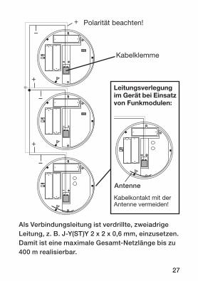
Leitungsverlegung im Gerät bei Einsatz von Funkmodulen:
J4
J3
J2
J1
J6
J5
Kabelkontakt mit derAntenne vermeiden!
J4
J3
J2
J1
J6
J5
Polarität beachten!+
–
+
–
Kabelklemme
+
–
Antenne
Als Verbindungsleitung ist verdrillte, zweiadrige Leitung, z. B. J-Y(ST)Y 2 x 2 x 0,6 mm, einzusetzen. Damit ist eine maximale Gesamt-Netzlänge bis zu 400 m realisierbar.
28
Bis zu 40 Rauchmelder sind drahtgebunden vernetzbar.- Verlegen Sie die Verbindungsleitung wie in der
Skizze gezeigt. Beachten Sie bei der gesamten Verkabelung die Polarität der Anschlüsse.
- Wenn eine „Aufputzinstallation“ ausgeführt wer-den muss, montieren Sie den Rauchmelder unter Zuhilfenahme der mitgelieferten Abstandshalter, damit die Leitung, ohne sie zu quetschen, in das Gerät geführt werden kann.
- Führen Sie die Leitung durch die Öffnung des Sockels hindurch und fixieren Sie sie in der ge-wünschten Länge mit einem Kabelbinder am Hal-ter des Sockels. Beachten Sie, dass Sie genügend Länge stehen lassen, um später einen problem-losen Batteriewechsel ausführen zu können.
- Isolieren Sie die Leitungsenden auf eine Länge von ca. 6 mm ab.
- Ziehen Sie die Kabelklemme ab und stecken Sie die abisolierten Leitungsenden in die Klemmen. Beachten Sie dabei die richtige Polarität lt. Skizze und Polaritätseinprägung im Gehäuse vor dem Platz der Kabelklemme.
- Setzen Sie die Kabelklemme wieder ein und kontrollieren Sie nochmals die richtige Polarität der Verkabelung.
29
- Setzen Sie den Rauchmelder auf den Sockel auf. Achten Sie dabei darauf, dass die Leitung beim Aufsetzen des Rauchmelders auf den Sockel nicht von der Neoprendichtung eingeklemmt wird. Überschüssiges Kabel kann im Modul-schacht vor der Kabelklemme untergebracht werden. Bitte beachten Sie, dass zu viel Kabel oberhalb der Modulabdeckung die Funkübertra-gung beeinträchtigen kann.
- Führen Sie bei jedem so montierten Rauchmel-der eine Funktionsprüfung nach Kapitel 9.1 aus. Bei der normalen (periodischen) Funktionsprü-fung durch Durchdrücken der Prüftaste bis zum Druckpunkt für ca. 2 Sekunden wird nur der gerade bediente Rauchmelder aktiviert. Erst bei einem Rauchalarm (Zigarettenrauch o. Ä.) werden alle angeschlossenen Rauchmelder mit ausgelöst. Allerdings blinkt nur am auslö-senden Rauchmelder die rote Leuchtdiode in der Prüftaste. Bei ausbleibender Weiterleitung oder einem ständigen Fehlalarm die Polung der Verbindungsleitung überprüfen!
30
11 Auslieferungszustand wiederherstellen
Zum Zurücksetzen des Funk-Rauchmelders in den Auslieferungszustand muss der Taster des Funkmoduls zuerst für etwa 5 Sekunden gedrückt werden, bis die LED des Funkmoduls rot zu blinken beginnt. Anschließend muss der Taster erneut für etwa 5 Sekunden gedrückt werden. Die LED blinkt jetzt schneller. Nach dem Loslassen des Tasters wird der Funk-Rauchmelder in den Auslieferungs-zustand zurückgesetzt.
12 Batteriewechsel
Sind die Batterien erschöpft, so meldet der Rauch-melder dies mit einem kurzen Alarmton, der sich alle 48 Sek. wiederholt, sowie dreimaligem Blinken der roten Leuchtdiode in der Prüftaste alle 48 Sek. Dann sollte man baldmöglichst die Batterien aus-tauschen. Die Lebensdauer eines neuen Batterie-satzes (Alkaline-Typ) beträgt mehr als 2 Jahre (typ. Wert, ohne Alarmierung).
31
Batterien können wie folgt gewechselt werden:- Nehmen Sie den Rauchmelder durch Drehen
gegen den Uhrzeigersinn vom Sockel ab.- Nehmen Sie die verbrauchten Batterien aus den
Bat teriefächern.- Legen Sie drei neue LR6-Batterien (Mignon/AA)
entsprechend der Polkennzeichnung in die Batteriefächer ein (siehe Skizze auf Seite 17, der Einsatz von 1,2-V-Akkus ist nicht zulässig). Nach Einlegen der Batterien leuchtet die LED des Funkmoduls nacheinander kurz in den Farben rot, grün und orange auf und die rote Kontroll-leuchte in der Prüftaste blinkt ca. alle 48 Sek. auf und signalisiert so die Betriebsbereitschaft des Gerätes.
- Rasten Sie den Rauchmelder durch Drehen im Uhrzeigersinn in den Sockel ein. Bei der rich-tigen Positionierung helfen die im Sockel und im Rauchmelder angebrachten roten Dreiecke.
Vorsicht! Explosionsgefahr bei unsachgemäßem Austausch der Batterie.
Verbrauchte Batterien gehören nicht in den Hausmüll! Entsorgen Sie diese in Ihrer örtlichen Batteriesammelstelle!

32
13 Zusätzliche Hinweise – bitte beachten!
Hinweise zu Reichweite und Störungen:Das eingesetzte Funksystem arbeitet im 868-MHz-Bereich, der auch von anderen Funk-diensten genutzt wird. Daher kann es durch Geräte, die auf der gleichen bzw. benachbarten Frequenz arbeiten, zu Einschränkungen des Be-triebs und der Reichweite kommen.Die angegebene Reichweite von bis zu 100 m ist die Freifeldreichweite, d.h. die Reichweite bei Sichtkontakt zwischen Sender und Empfänger. Im praktischen Betrieb befinden sich jedoch Wände, Zimmerdecken usw. zwischen Sender und Emp-fänger, wodurch sich die Reichweite entsprechend reduziert. Weitere Ursachen für verminderte Reichweite:- Hochfrequenzstörungen aller Art.- Bebauung jeglicher Art und Vegetation.- Im Nahbereich der Geräte bzw. innerhalb oder
nahe der Funkstrecke befinden sich leitende Teile, die zu Feldverzerrungen und -abschwä-chungen führen.
- Der Abstand von Sender oder Empfänger zu
33
leitenden Flächen oder Gegenständen (auch zum menschlichen Körper oder Boden) beeinflusst die Strahlungscharakteristik der Antennen und somit die Reichweite.
- Breitbandstörungen in städtischen Gebie-ten können Pegel erreichen, die den Signal-Rauschabstand verkleinern, wodurch sich die Reichweite verringert.
- Mangelhaft abgeschirmte PCs können in den Empfänger einstrahlen und die Reichweite ver-ringern.
34
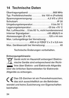
Entsorgungshinweis: Gerät nicht im Hausmüll entsorgen! Elektro-nische Geräte sind entsprechend der Richt-linie über Elektro- und Elektronik-Alt geräte
über die örtlichen Sammelstellen für Elektronik-Altgeräte zu entsorgen.
Das CE-Zeichen ist ein Freiverkehrszeichen, das sich ausschließlich an die Behörden
wendet und keine Zusicherung von Eigenschaften beinhaltet.
14 Technische DatenÜbertragungsband: . . . . . . . . . . . . . . . . . . .868 MHzTyp. Freifeldreichweite: . . . . . . . bis 100 m (Freifeld)Spannungsversorgung: . . . . . . . . . . . .4,5 V/3 x LR 6Schutzart: . . . . . . . . . . . . . . . . . . . . . . . . . . . . . . IP 30Umgebungstemperatur:. . . . . . . . . . . . . . 0 bis 50 ˚CLagerungstemperatur: . . . . . . . . . . . . .-25 bis +70 ˚CRel. Luftfeuchte: . . 5 bis 93 %, nicht kondensierendInterner Signalgeber: . . . . . . . . . . . . . >85 dB(A)/3 mAbmessungen (D x H): . . . . . . . . . . . . . .120 x 44 mmMax. Leitungslänge bei Vernetzung: . . . . . . . . . . . . . . . . . .400 m (J-Y(St)Y 2 x 2 x 0,6 mmMax. Geräteanzahl bei Vernetzung: . . . . . . . . . . . 40
Technische Änderungen vorbehalten.
35
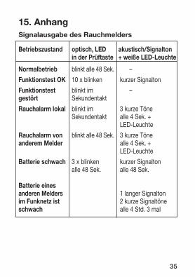
15. Anhang Signalausgabe des Rauchmelders
Betriebszustand optisch, LED akustisch/Signalton in der Prüftaste + weiße LED-Leuchte
Normalbetrieb blinkt alle 48 Sek. –
Funktionstest OK 10 x blinken kurzer Signalton
Funktionstest blinkt im –gestört Sekundentakt
Rauchalarm lokal blinkt im 3 kurze Töne Sekundentakt alle 4 Sek. + LED-Leuchte
Rauchalarm von blinkt alle 48 Sek. 3 kurze Töneanderem Melder alle 4 Sek. + LED-Leuchte
Batterie schwach 3 x blinken kurzer Signalton alle 48 Sek. alle 48 Sek.
Batterie eines anderen Melders 1 langer Signaltonim Funknetz ist 2 kurze Signaltöneschwach alle 4 Std. 3 mal
36
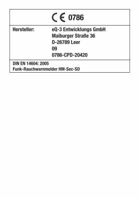
DIN EN 14604: 2005Funk-Rauchwarnmelder HM-Sec-SD
Hersteller: eQ-3 Entwicklungs GmbH Maiburger Straße 36 D-26789 Leer 09 0786-CPD-20420
0786

37
38
1. English edition 05/2009Documentation © 2009 eQ-3 Ltd., Hong KongAll rights reserved. No parts of this manual may be reproduced or processed in any form using electronic, mechanical or chemical processes in part or in full without the prior explicit written permission of the publisher.It is quite possible that this manual has printing errors or defects. The details provided in this manual are checked regularly and corrections are done in the next edition. We do not assume any lia-bility for technical or printing errors. All registered trade marks and copyrights are acknowledged. Printed in Hong KongWe reserve the right to make changes due to technical advancements without prior notice.
83454 / V 1.1
39
Table of contents
1 Information about these instructions . . . . . 412 Hazard information . . . . . . . . . . . . . . . . . . . . 423 General information and function . . . . . . . . 423.1 Intended use . . . . . . . . . . . . . . . . . . . . . . . . . 433.2 Safety and maintenance instructions . . . . . 444 General system information on HomeMatic . . . 465 General information about radio operation . .466 Installation . . . . . . . . . . . . . . . . . . . . . . . . . . . . . .476.1 Installation locations and instructions . . . . . . .476.2 Mounting the detector . . . . . . . . . . . . . . . . . . . .517 Start-up. . . . . . . . . . . . . . . . . . . . . . . . . . . . . . . . .527.1 Inserting batteries . . . . . . . . . . . . . . . . . . . . . . . .527.2 Overview of wireless module operation . . . . . .537.3 Latching the smoke detector onto the base . .548 Teaching-in. . . . . . . . . . . . . . . . . . . . . . . . . . . . . .558.1 Teaching-in wireless smoke detectors
to one another . . . . . . . . . . . . . . . . . . . . . . . . . . .558.2 Teaching-in wireless smoke detectors
to other HomeMatic components . . . . . . . . . .569 Function check and operation. . . . . . . . . . . . . .589.1 Function check for smoke detector . . . . . . . . .589.2 Periodic checking and indication of errors . . .609.3 Testing the wireless network . . . . . . . . . . . . . . .61
40
10 Wired networking of several smoke detectors . . . . . . . . . . . . . . . .62
11 Restoring the initial state . . . . . . . . . . . . . . . . . .6512 Battery replacement . . . . . . . . . . . . . . . . . . . . . .66 13 Additional notes to be taken into account . . . .6814 Technical data . . . . . . . . . . . . . . . . . . . . . . . . . . .7015 Appendix . . . . . . . . . . . . . . . . . . . . . . . . . . . . . . .71
41
1 Information about these instructions
Read these instructions carefully before beginning operation with your HomeMatic components. Keep the instructions handy for later consultation! Please hand over the operating manual as well when you hand over the device to other persons for use.
Attention! This indicates a hazard.
Note. This section contains additional important information!
42
2 Hazard information
Do not open the device: it does not contain any components that need to be serviced by
the user. In the event of an error, please return the device to our service department. The device may only be operated indoors and must be protected from the effects of damp and dust, as well as solar or other methods of heat radiation.
3 General information and function
This smoke detector monitors a room for smoke emissions based on the photoelectric scattered light principle. This enables a fire to be detected whilst still in its very early stages and a warning to be given that dangerous smoke gases are present. The detector raises the alarm by means of an integrated siren, plus a red warning LED and a white LED (emergency lighting in the event of a power failure) that work in parallel. The HM-Sec-SD wirelessly sends a smoke alarm to all wireless smoke detectors of the same type
43
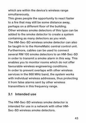
which are within the device’s wireless range simultaneously. This gives people the opportunity to react faster to a fire that may still be some distance away, perhaps on a different floor of the building.Other wireless smoke detectors of this type can be added to the smoke detector to create a system containing as many detectors as you wish.The HM-Sec-SD wireless smoke detector can also be taught-in to the HomeMatic central control unit.Furthermore, cables can be used to connect several RM 100 smoke detectors to an HM-Sec-SD in order to transmit a smoke alarm in this way. This enables you to monitor rooms which do not offer favourable wireless engineering conditions.In order to prevent overlaps with other wireless services in the 868 MHz band, the system works with individual wireless addresses, thus protecting it from false alarms sent by other wireless transmitters in this frequency range.
3.1 Intended use
The HM-Sec-SD wireless smoke detector is intended for use in a network with other HM-Sec-SD wireless smoke detectors.
44
The wireless smoke detector may not be used in environments where the transmission of wireless signals may interfere with equipment, for example, in medical facilities containing life-saving systems or other similar environments.The mounting notes contained in this manual must be observed in order to ensure proper functioning.The device must not be modified in any way.The manufacturer accepts no responsibility for the consequences of improper use, which will also render all warranty claims invalid.
3.2 Safety and maintenance instructions
- If you have any doubts about the method of operation, safety or connection of the device, please enlist the help of an expert or contact our service department.
- Do not use the device if there are signs of damage to the housing, control elements or connecting cables, for example, or if it demonstrates a malfunction. If you have any doubts, have the device checked by an expert or by our service department.
- Do not open the device except to replace the batteries or to carry out cabling or coding work:
45
it does not contain any components that you will need to service. In the event of an error, please return the faulty device to our service department.
- The device may only be operated indoors and must be protected from the effects of damp, dust and direct solar radiation.
- The system must not be kept or operated in a location that is accessible to children. It is not a toy!
- Do not leave packaging material lying around. Plastic films/bags, pieces of polystyrene, etc. can be dangerous in the hands of a child.
- The only maintenance required is to wipe the housing with a slightly damp cloth every 6 months.
- The smoke detector must not be painted over or covered with wallpaper.
- Press the test button to check the device function once a month.
46
4 General system information on HomeMatic
This device is a part of the HomeMatic home control system and works with the bi-directional BidCoS® wireless protocol. All devices are delivered in a standard configuration. The functionality of the device can also be configured with a programming device and software. The additional functions that can be made available in this way and the supplementary functions provided by the HomeMatic system when it is combined with other components are described in the separate Configuration Instructions and in the HomeMatic System Manual.
All current technical documents and updates are provided at www.HomeMatic.com.
5 General information about radio operation
Radio transmission is performed on a non-exclusi-ve transmission path, which means that there is a
47
possibility of interference occurring. Interference can be caused by switching operations, electrical motors or defective electrical devices.
The range of transmission within buildings can deviate greatly from open air distances.
Besides the transmitting power and the reception characteristics of the receiver, environmental influences such as humidity in the vicinity and local structures also play an important role.
eQ-3 Entwicklung GmbH hereby declares that thisdevice conforms with the essential requirements andother relevant regulations of Directive 1999/5/EC.The full declaration of conformity is provided under www.HomeMatic.com.
6 Installation
6.1 Installation locations and instructions
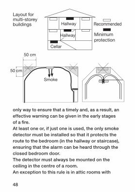
It is always recommended to install several smoke detectors in the building or flat in question. In any event, one smoke detector must be installed on each floor of a multi-storey building. This is the
48
only way to ensure that a timely and, as a result, an effective warning can be given in the early stages of a fire.At least one or, if just one is used, the only smoke detector must be installed so that it protects the route to the bedroom (in the hallway or staircase), ensuring that the alarm can be heard through the closed bedroom door. The detector must always be mounted on the ceiling in the centre of a room. An exception to this rule is in attic rooms with
Flur
Flur
Keller
Flur
Flur
Keller
Flur
Flur
Keller
Layout for multi-storey buildings Recommended
Minimum protection
50 cm
50 cm
Smoke
49
pitched roofs. Here, the smoke detector must not be installed at the apex of the roof. If it is to be installed on the roof, it must be mounted around 1 m below the room’s highest point or, even better, on a (roof) beam.This is because a build up of air near to walls, and particularly in the corners of a room and at the apex of a pointed roof, stops the rising smoke from reaching the walls or the corners of the room. For this reason, a smoke detector must never be installed within approximately 50 cm of the corners of a room. A smoke detector installed in this area would be ineffective in an emergency situation and would raise the alarm too late.To check that the installation location is acceptable in terms of the smoke detector’s audible alarm, trigger a test alarm (see Section 9, “Function check and operation”) whilst someone is sleeping in the bedroom. The smoke detector really has to wake you up; it’s no good if you can only just hear it when you’re already awake.Finally, when at its installation location each smoke detector must be thoroughly tested to ensure that it can access the central control unit wirelessly in all circumstances.
50
In order to safeguard against false alarms, a smoke detector should not be installed in the following rooms or locations:- Kitchen/bathroom: a lot of steam in these rooms
will trigger false alarms- Rooms with open fireplaces: risk of false alarms- In the immediate vicinity of halogen lamps,
transformers or halogen lamp cable systems, as well as fluorescent lamps or energy-saving lamps (minimum distance 50 cm)
- Garages: exhaust emissions (fumes) will lead to false alarms
- Dusty and dirty rooms: measuring chamber gets dirty quickly or false alarms are triggered
- In the vicinity of windows, ventilators, fans or any other locations where the air moves around a lot
- In the vicinity of areas where people smoke; tobacco smoke will lead to false alarms
- In the vicinity of solid steel beams, large metal surfaces, etc. as they could significantly inhibit the transmission or receipt of the wireless signal. Moving the detector by just a few centimetres can often be a great help here.
51
J4�
J3�
J2�
J1�
J6�
J5�
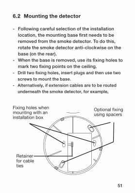
Fixing holes when mounting with an installation box
Optional fixing using spacers
Retainer for cable ties
6.2 Mounting the detector
- Following careful selection of the installation location, the mounting base first needs to be removed from the smoke detector. To do this, rotate the smoke detector anti-clockwise on the base (on the rear).
- When the base is removed, use its fixing holes to mark two fixing points on the ceiling.
- Drill two fixing holes, insert plugs and then use two screws to mount the base.
- Alternatively, if extension cables are to be routed underneath the smoke detector, for example,
52
the detector can also be mounted using the two supplied spacers to create a gap between the ceiling and the base. The two fixing apertures corresponding to the spacers should be used for mounting (see diagram).
Furthermore, the smoke detector can be fixed in place using a standard installation box. The two installation box fixing holes should be used for this purpose.
- Avoid mounting the smoke detector in the vicinity of solid steel beams, large metal surfaces, etc. as they could significantly inhibit the transmission or receipt of the wireless signal. Moving the detector by just a few centimetres can often be a great help here.
7 Start-up
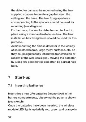
7.1 Inserting batteries
Insert three new LR6 batteries (mignon/AA) in the battery compartments, observing the polarity shown (see sketch).Once the batteries have been inserted, the wireless module LED lights up briefly red, green and orange in
53
LED des Funkmoduls
Taster des Funkmoduls
Funkmodul
Polarity of batteries and control elements on the rear of the device
sequence and the red indicator light in the test button at the front of the device flashes approximately every 48 seconds, which signals that the device is ready for operation.
7.2 Overview of wireless module operation
The audible signalling device (buzzer) of the wireless module acknowledges each short and long (around five seconds) press of the wireless module button. The LED provides a visual indication of the current status.
54
Brief button press: teach-in/configuration mode- LED flashes orange- Brief button press: exit teach-in/
configuration mode- LED red: teach-in failed- LED green: teach-in successful
Long button press: menu- LED flashes red- Brief button press: test the wireless network- Long button press: reset to the initial state
7.3 Latching the smoke detector onto the base
If no more settings need to be made on the wireless module, the smoke detector can be latched onto the base. Latch the smoke detector onto the base by rotating it clockwise. The red triangles shown on the base and the smoke detector will help you to position the detector correctly.
Please note!If batteries have not been inserted, it will not be possible to attach the smoke detector tothe base.
55
8 Teaching-in
8.1 Teaching-in wireless smoke detectors to one another
To teach-in two wireless smoke detectors to one another, the wireless module button of one of the smoke detectors must first be pressed briefly, followed by the wireless module button of the other smoke detector within 20 seconds. The visual signals emitted by the LEDs on the wireless modules of both smoke detectors must end with a green light displayed for around two seconds.
During the teach-in procedure, the wireless smoke detectors must be positioned at least one metre away from one another; if the distance between the two is too short this could lead to wireless signals not being received correctly due to their level of intensity being too high.A wireless network is formed by teaching-in two wireless smoke detectors to one another. If one wireless smoke detector in the network emits a smoke alarm, this is automatically indicated to all the other wireless smoke detectors in that network.
56
All you have to do to integrate a new wireless smoke detector into an existing wireless network is teach it in to a wireless smoke detector that is already part of that network.To remove a wireless smoke detector from a wireless network, it must be reset to the initial state. It can then be integrated into a different wireless network or it can be taught-in to another wireless smoke detector that is also in the initial state to form a new wireless network.
8.2 Teaching-in wireless smoke detectors to other HomeMatic components
A network of wireless smoke detectors can serve as a sensor for a HomeMatic actuator. For this to work, the actuator (for switching a lamp on/off, for example) must be taught-in to a wireless smoke detector in the network. To execute the teach-in procedure, both of the devices to be connected must be in teach-in mode. To switch the wireless smoke detector to teach-in mode, briefly press the wireless module button. The wireless module LED flashes orange. If no teach-in is carried out, teach-in mode will be exited automatically after 20 seconds.
57
Note: If the smoke detector has already been taught-in to a central control unit and
is thus blocked for direct teach-in, it can still be put into teach-in mode as described above, but teaching-in will not be performed and the wireless module LED will light up red for two seconds.In the standard configuration, the smoke detector configures the actuator such that it is activated by a smoke alarm and deactivated again when the corresponding all-clear is given.All devices are supplied with a standard configu-ration. For information on the supplementary functions which you can benefit from by using the HomeMatic system in conjunction with other components, please refer to the HomeMatic system manual.
58
9 Function check and operation
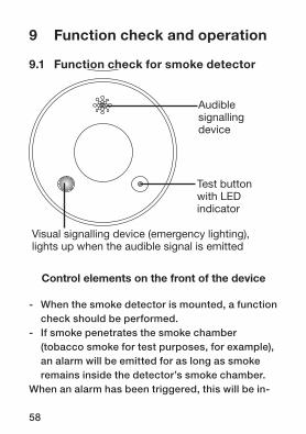
9.1 Function check for smoke detector
- When the smoke detector is mounted, a function check should be performed.
- If smoke penetrates the smoke chamber (tobacco smoke for test purposes, for example), an alarm will be emitted for as long as smoke remains inside the detector’s smoke chamber.
When an alarm has been triggered, this will be in-
J4�
J3�
J2�
J1�
J6�
J5�
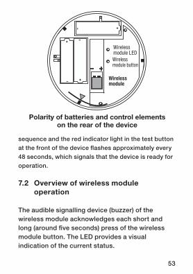
Audible signalling device
Test buttonwith LED indicator
Visual signalling device (emergency lighting),lights up when the audible signal is emitted
Control elements on the front of the device
59
dicated on the smoke detector itself by means of an audible and a visual signal, emitted roughly every second.- The alarm stops automatically after 48 seconds
and when all the test smoke has escaped from the smoke chamber.
- Press the test button for around two seconds until you feel pressure on your finger; this will deactivate the audible alarm for approximately 10 minutes. If there is still smoke inside the smoke chamber, the LED in the test button will continue to flash. If there is no more smoke inside the smoke chamber, the test button can be used to stop the alarm completely.
- If a wireless smoke detector triggers a smoke alarm, all other wireless smoke detectors that are located within the wireless range of the first detector and have been taught-in to the wireless network start to emit visual and audible signals too (delayed by up to 16 seconds as a result of wireless transmission).
- If the test button on the smoke detector that has triggered the alarm is pressed for around two seconds, all the smoke detectors in the system receive a wireless all-clear signal. This stops all smoke detectors in the wireless network from
60
sending signals (delayed by up to 16 seconds as a result of wireless transmission).
- So that the detector that has triggered the alarm can be identified (in the event of a false alarm, for example), its red indicator LED in the test button continues to flash for 10 minutes.
9.2 Periodic checking and indication of errors
The smoke detector function must be checked once a month by pressing the test button for around two seconds until you feel pressure on your finger:- If the audible signal is emitted once and the LED
in the test button flashes 10 times, the smoke detector is working correctly.
- If only the LED flashes when the button is pressed, the smoke detector is faulty and needs to be replaced.
- If no signals are emitted, first check whether the batteries have been inserted with the correct polarity. If they have, check the batteries and, if necessary, replace them. If the batteries are in working order, the smoke detector is faulty and needs to be replaced.
61
9.3 Testing the wireless network
You can check if a wireless smoke detector belongs to a wireless network by sending a wireless test signal to that smoke detector. To create the wireless test signal, the wireless module button must first be pressed for around five seconds, until the wireless module LED starts to flash red. The button must then be pressed once again, this time briefly. The wireless test signal is now sent.All wireless smoke detectors that belong to the wireless network respond to this signal by emitting three short beeps from the audible signalling device (buzzer) of the wireless module 10 times, every eight seconds.The wireless test signals are only evaluated by the wireless modules of wireless smoke detectors. They are not evaluated further by the smoke detectors themselves, nor are they forwarded via the wired network (if present). Other taught-in HomeMatic components do not respond to wireless test signals.A smoke alarm must be triggered (by cigarette smoke, for example) in order to test all the components in the system.
62
10 Wired networking of several smoke detectors
If one or more smoke detectors has or have to be mounted at a location where only a limited wireless connection is available due to a building’s reinforcements being well shielded or due to electromagnetic interference, several smoke detectors can be networked using wires in order to ensure that signals can be sent and received properly.This type of network also increases signalling reliability at locations that, in addition to the restrictions mentioned above, are some distance away or are sound insulated, as when one smoke detector triggers an alarm, all the connected smoke detectors also set off their alarms. However, as the LED in the test button only flashes on the smoke detector that has triggered the alarm, this detector can be easily identified.A twisted, two-wire cable such as a J-Y(ST)Y 2 x 2 x 0.6 mm should be used as the connecting cable. This ensures that a maximum overall network length of up to 400 m is possible.Up to 40 smoke detectors can be networked using wires.
63
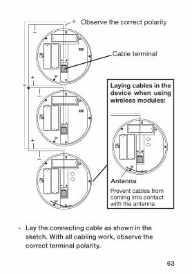
Laying cables in the device when using wireless modules:
J4
J3
J2
J1
J6
J5
Prevent cables from coming into contact with the antenna.
J4
J3
J2
J1
J6
J5
Observe the correct polarity+
–
+
–
Cable terminal
+
–
Antenna
- Lay the connecting cable as shown in the sketch. With all cabling work, observe the correct terminal polarity.
64
- If the smoke detector has to be surface-mounted, use the spacers supplied to mount the smoke detector such that the cable can be routed into the device without being pinched.
- Feed the cable through the opening on the base and use a cable tie to fix the required length in place on the retainer on the base. Make sure that you leave a sufficient length of cable so that the batteries can be easily replaced at a later time.
- Strip around 6 mm at the ends of the cable.- Pull the cable terminal off and insert the
stripped cable ends into the terminals. Observe the correct polarity as per the sketch and in accordance with the stamp inside the housing in front of the cable terminal.
- Reinsert the cable terminal and check again that the cabling has the correct polarity.
- Attach the smoke detector to the base. In doing so, make sure that the cable is not pinched by the neoprene seal when the smoke detector is attached to the base. Any surplus cable can be housed in the module receptacle in front of the cable terminal. Please note that an excessive amount of cable above the module cover can impair wireless transmission.
65
- For each smoke detector mounted in this way, perform a function check as per Section 9.1. A standard (periodic) function check executed by pressing the test button for around two seconds until you feel pressure on your finger only activates the smoke detector currently being operated. Only when a smoke alarm is triggered (by cigarette smoke or similar) will all connected smoke detectors also be activated. However, the red LED in the test button only flashes on the smoke detector that has triggered the alarm. If the signal is not transmitted or if a false alarm is constantly emitted, check the polarity of the connecting cable.
11 Restoring the initial state
To reset the wireless smoke detector to the initial state, the wireless module button must first be pressed for around five seconds, until the wireless module LED starts to flash red. Then press the button again for approximately five seconds. The LED now starts to flash faster. When the button is released, the wireless smoke detector is reset to the initial state.
66
12 Battery replacement
If the batteries are empty, the smoke detector will indicate this with a short beep every 48 seconds and the red LED in the test button will also flash three times every 48 seconds. If this happens, the batteries should be replaced as soon as possible. A new set of (alkaline) batteries has a service life of over two years (typical value, with no alarms).
Replacing of batteries:- Rotate the smoke detector anti-clockwise to
remove it from the base.- Remove the used batteries from the battery
compartments.- Insert three new LR6 batteries (mignon/AA)
in the battery compartments, observing the polarity shown (see sketch on page 50; the use of 1.2 V batteries is not permitted). Once the batteries have been inserted, the wireless module LED lights up briefly red, green and orange in sequence and the red indicator light in the test button flashes approximately every 48 seconds, which signals that the device is ready for operation.
- Latch the smoke detector onto the base by
67
rotating it clockwise. The red triangles shown on the base and the smoke detector will help you to position the detector correctly.
Caution! Danger of explosion if battery is replaced improperly.
Used batteries are not to be disposed of with the household waste! Please dispose them at your local battery collection point!
68
13 Additional notes to be taken into account
Ranges and interfences:The wireless system used operates in the 868 MHz band, which is also used by other wireless services. This means that devices operating on the same or an adjacent frequency can lead to restrictions in terms of operation and range.The specified range of up to 100 m is the open air range, i.e. the range when the transmitter and the receiver can “see” each other. In practice, however, there will be walls, ceilings, etc. between the transmitter and receiver, which will reduce the range accordingly. Other reasons for a reduced range: - All types of radio frequency interference - Buildings of all types and vegetation - Conductive components that could distort and
weaken the field are located in the vicinity of the devices or on or near to the transmission path.
- The distance from the transmitter or receiver to conductive surfaces or objects (or to floors or human bodies) has an effect on the radiation
69
characteristics of the antennas and, as a result, on the range.
- In urban areas, broadband interference can reach levels which reduce the signal to noise ratio and, as a consequence, the range.
- PCs with insufficient shielding can radiate to receivers, thus reducing the range.
70
Note on disposal: Do not dispose of the device as part of household waste! Electronic devices are to be disposed of in accordance with the
guidelines concerning electrical and electronic devices via the local collection point for old electronic devices.
The CE sign is a free trade sign addressed exclusively to the authorities and does notinclude any warranty of any properties.
14 Technical dataTransmission band: ......................................868 MHzTyp. open air range: ................ up to 100 m (open air)Power supply: ........................................4.5 V/3 x LR6Degree of protection: .......................................... IP30Ambient temperature: ..................................0 to 50˚CStorage temperature: ............................. -25 to +70˚CRel. humidity: ..................5 to 93%, non-condensingInternal signalling device: ...................>85 dB(A)/3 mDimensions (D x H): ................................120 x 44 mmMax. cable length for networking: 400 m (J-Y(St)Y 2 x 2 x 0.6 mm)Max. number of devices for networking: ...............40
Subject to technical alterations.
71
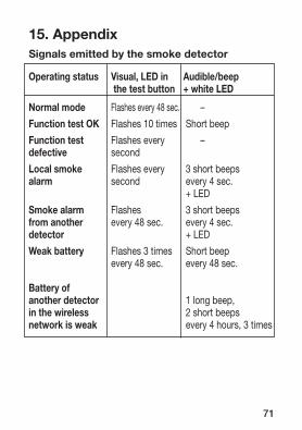
15. Appendix Signals emitted by the smoke detector
Operating status Visual, LED in Audible/beep the test button + white LED
Normal mode Flashes every 48 sec. –
Function test OK Flashes 10 times Short beep
Function test Flashes every –defective second
Local smoke Flashes every 3 short beepsalarm second every 4 sec. + LED
Smoke alarm Flashes 3 short beepsfrom another every 48 sec. every 4 sec. detector + LED
Weak battery Flashes 3 times Short beep every 48 sec. every 48 sec.
Battery of another detector 1 long beep, in the wireless 2 short beepsnetwork is weak every 4 hours, 3 times
72
eQ-3 AG Maiburger Straße 29 D-26789 Leerwww.eQ-3.com
DIN EN 14604: 2005Radio-controlled smoke detector HM-Sec-SD
Manufacturer: eQ-3 Entwicklungs GmbH Maiburger Straße 36 D-26789 Leer 09 0786-CPD-20420
0786


![Rakonitzer Kreis [Rakovnický kraj] - pvh.ff.cuni.czpvh.ff.cuni.cz/zidi/Rakovnicko_1799.pdf · Rakonitzer Kreis [Rakovnický kraj] Verzeichnis der auf obigen Gütern befindlichen](https://img.pdfslide.org/doc/110x75/5d5e04ed88c9936f1b8b8bf0/rakonitzer-kreis-rakovnicky-kraj-pvhffcuniczpvhffcuniczzidirakovnicko1799pdf.jpg)