Embed Size (px)
Citation preview
www.gewes.com
GEWES
CustomizedCardan shafts
350 Nm -600.000 Nm
350 Nm -600.000 Nm
www.gewes.com
GEWES
2
盖 威 狮 ( G E W E S ) 万 向 传 动 轴 有 限 公 司 位 于 德 国 图 林 根(Thuringia)州的施塔特伊尔姆(Stadtilm)市,地理位置优越,交通便捷。
公司所在地位于从法兰克福(Frankfurt)经由巴特赫斯菲尔德(Bad Herfeld)至德累斯顿 (Dresden) 的 A5/A4高速公路,以及通往南方的 A71/A73 高速公路附近。
盖威狮(GEWES)员工具有高超的专业技能,这也使得公司成为欧洲最富盛名的万向传动轴生产厂家之一。
1942年,当 Rheinmetall Borsig 股份公司将它的万向轴生产厂搬迁到施塔特伊尔姆(Stadtilm)市后,这里便开始了此类产品的生产历史。除了战后短暂的停产,万向传动轴在这里的生产持续至今。
在几十年的生产实践中,一批具有丰富经验的专家型员工,对万向传动轴的产品设计、制造工艺以及生产组织进行了持续的发展、改进。
盖威狮(GEWES)是家私营企业,拥有员工380余人。
GEWES is located in Stadtilm, a town in Thuringiawith excellent traffic links to all directions.The motorways from Frankfurt via Bad Hersfeld toDresden (A 5, A 4) and the motorways A 71 / A 73to the South are not far away.GEWES employs highly skilled specialist workersand is one of Europe's most experiencedmanufacturers of cardan shafts.Cardan shaft production started in Stadtilm in1942, when Rheinmetall Borsig AG shifted itsproduction facility here. Discounting a shortinterruption after the war, cardan shafts have beenmade in Stadtilm ever since.Over the course of several decades, a group ofhighly experienced specialists have developed indesign, process scheduling and production ofcardan shafts.GEWES is a privately owned company with aworkforce of more than 380 employees.
此样本 2016 版的版权归盖威狮(GEWES)所有。
未经书面授权禁止全部或部分转载。
Copyright 2016 by Gelenkwellenwerk Stadtilm GmbHAll rights reserved.This publication must not be duplicated in whole or inpart without our prior written permission.
地理位置和历史 Location and history
注意:
我们不对样本中出现的错误和疏漏承担责任。
为了更好地使用本公司产品,在必要时,请咨询盖威狮(GEWES)公司技术部门。
本目录代替所有早期版本。
必要时会做进一步修改。
Note:We will not be liable for any errors or omissions in thiscatalogue.Technical consultation with GEWES GelenkwellenwerkStadtilm GmbH is a necessity to ensure the properfunction of the products.This catalogue supersedes all earlier editions.Subject to modifications.
www.gewes.com
GEWES
3
目录##产品概述
产品型号
万向传动轴-延伸产品
说明
极限扭矩≤6200Nm的万向传动轴
极限扭矩8.8-25kNm的万向传动轴
极限扭矩28-55kNm的万向传动轴
极限扭矩55-200 kNm的万向传动轴
极限扭矩55-600 kNm的万向传动轴
极限扭矩≤200kNm的超短型万向传动轴
单万向联轴节/双万向联轴节
法兰/法兰螺栓
十字包组件
配对法兰
选型举例
万向传动轴应用建议
认证
联系方式
Contents##Product description
Model range
Cardan shaft - variants
Explanations
Cardan shafts up to 6200 Nm
Cardan shafts 8,8 ... 25 kNm
Cardan shafts 28 ... 55 kNm
Cardan shafts 55 ... 200 kNm
Cardan shafts 55 ... 600 kNm
Super short cardan shafts up to 200 kNm
Flange joints / Double joints
Flanges / Flange boltings
Journal cross assemblies
Companion flanges
Designation samples
Application engineering advice on the useof cardan shafts
Certifications
Contact
页码/Page
4
5
7
8
10
12
14
16
18
20
21
22
34
36
38
39
51
52
www.gewes.com
GEWES
4
万向传动轴是在具有空间偏移量的主传动轴和被驱动轴间,实现扭矩传递的最佳产品。在运转过程中,主/被动轴相对位置可以改变。
通过采用优异的结构组件,万向传动轴可以实现带有一定空间角度的移动以及轴向长度的变化。
#
因此万向轴成为机车和工业领域不可以或缺的传动组件。
#
万向传动轴特点:
##### » 应用广泛
##### » 效率高
##### » 可靠性强
##### » 维护成本低
##### » 使用便捷
万向传动轴在几乎所有需要机械驱动的工业领域都是必需的部件。
请您相信我们的产品会完美实现您的传动要求,让您满意。本手册可作参考资料。
No machine element other than a cardan shaftallows power transmission of torque betweenspacially offset driving and driven shafts whoseposition can be changed during operation.##Spatial angular motion and changes of axial lengthare ensured by advanced constructional elements.###Thus, cardan shafts have become an indis-pensable transmission component in automotiveengineering and industry.##Cardan shafts offer
##### » multifunctional application
##### » excellent efficiency
##### » high reliability
##### » low maintenance
##### » easy use##They are an integral part in almost all industrieswith mechanical drives.#Convince yourself that our products will solve yourdrive problems to your complete satisfaction. Thiscatalogue is intended as a source of readyreference.
我们期待着与您富有成效的合作!
We are looking forward to a fruitfulcooperation with you!
产品概述 General product description
www.gewes.com
GEWES
5
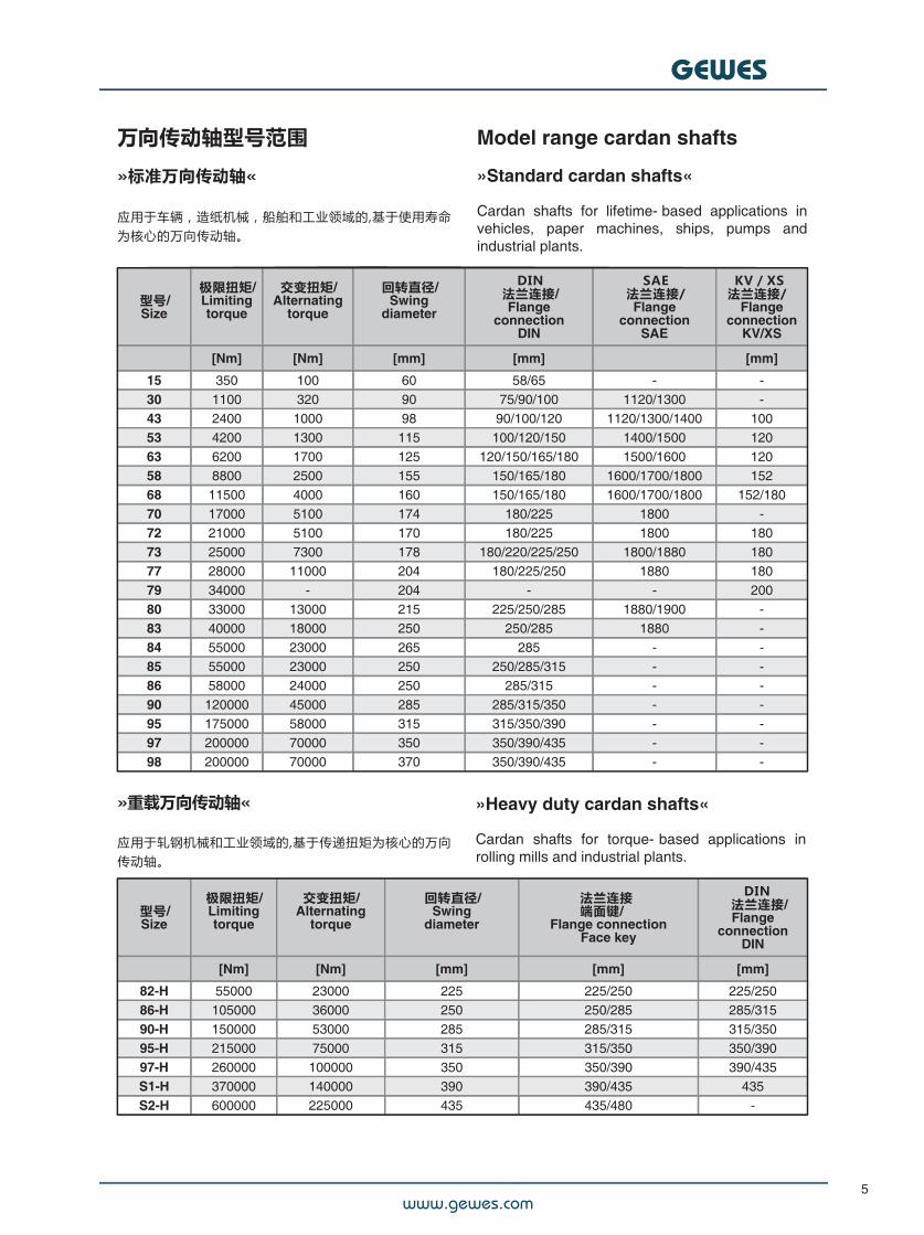
万向传动轴型号范围
»标准万向传动轴«
应用于车辆,造纸机械,船舶和工业领域的,基于使用寿命为核心的万向传动轴。
Model range cardan shafts
»Standard cardan shafts«
Cardan shafts for lifetime- based applications invehicles, paper machines, ships, pumps andindustrial plants.
型号/Size
极限扭矩/Limitingtorque
交变扭矩/Alternating
torque
回转直径/Swing
diameter
DIN法兰连接/Flange
connectionDIN
SAE法兰连接/Flange
connectionSAE
KV/XS法兰连接/
Flangeconnection
KV/XS
[Nm] [Nm] [mm] [mm] [mm]
15 350 100 60 58/65 - -30 1100 320 90 75/90/100 1120/1300 -43 2400 1000 98 90/100/120 1120/1300/1400 10053 4200 1300 115 100/120/150 1400/1500 12063 6200 1700 125 120/150/165/180 1500/1600 12058 8800 2500 155 150/165/180 1600/1700/1800 15268 11500 4000 160 150/165/180 1600/1700/1800 152/18070 17000 5100 174 180/225 1800 -72 21000 5100 170 180/225 1800 18073 25000 7300 178 180/220/225/250 1800/1880 18077 28000 11000 204 180/225/250 1880 18079 34000 - 204 - - 20080 33000 13000 215 225/250/285 1880/1900 -83 40000 18000 250 250/285 1880 -84 55000 23000 265 285 - -85 55000 23000 250 250/285/315 - -86 58000 24000 250 285/315 - -90 120000 45000 285 285/315/350 - -95 175000 58000 315 315/350/390 - -97 200000 70000 350 350/390/435 - -98 200000 70000 370 350/390/435 - -
»重载万向传动轴«
应用于轧钢机械和工业领域的,基于传递扭矩为核心的万向传动轴。
»Heavy duty cardan shafts«
Cardan shafts for torque- based applications inrolling mills and industrial plants.
型号/Size
极限扭矩/Limitingtorque
交变扭矩/Alternating
torque
回转直径/Swing
diameter
法兰连接端面键/
Flange connectionFace key
DIN 法兰连接/Flange
connectionDIN
[Nm] [Nm] [mm] [mm] [mm]
82-H 55000 23000 225 225/250 225/25086-H 105000 36000 250 250/285 285/31590-H 150000 53000 285 285/315 315/35095-H 215000 75000 315 315/350 350/39097-H 260000 100000 350 350/390 390/435S1-H 370000 140000 390 390/435 435S2-H 600000 225000 435 435/480 -
www.gewes.com
GEWES
6
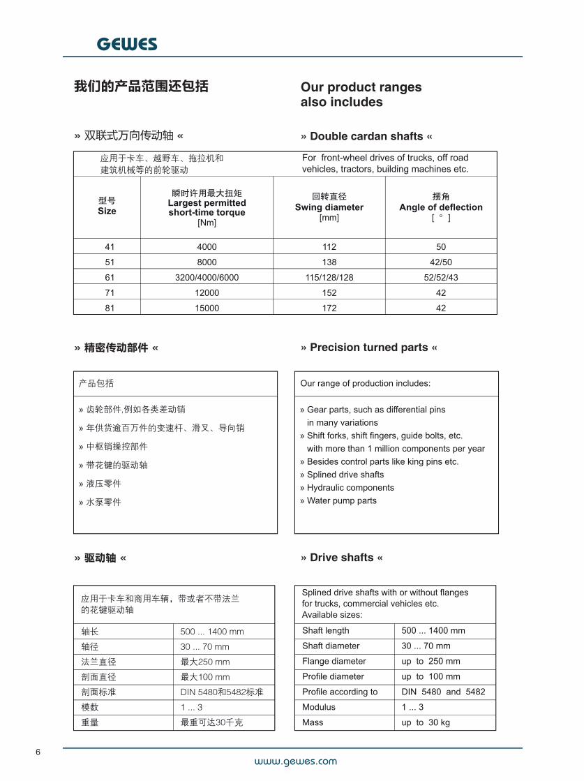
我们的产品范围还包括
» 双联式万向传动轴 «
Our product rangesalso includes
» Double cardan shafts «
» 精密传动部件 « » Precision turned parts «
» 驱动轴 « » Drive shafts «
www.gewes.com
GEWES
7
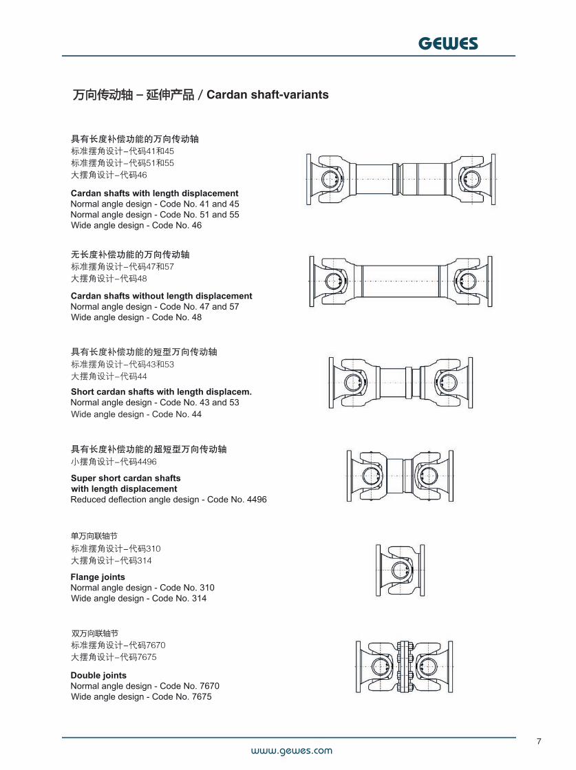
万向传动轴 – 延伸产品 / Cardan shaft-variants
双万向联轴节
单万向联轴节
www.gewes.com
GEWES
8
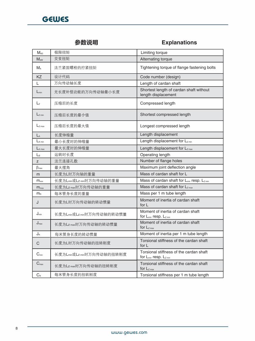
# 参数说明 Explanations
MdG Limiting torque
MdW Alternating torque
MA
#Tightening torque of flange fastening bolts
KZ Code number (design)
L Length of cardan shaft
Lmin
#
Shortest length of cardan shaft withoutlength displacement
LZ
#Compressed length#
LZ min
#Shortest compressed length#
LZ max
#Longest compressed length#
LA Length displacement
LA min Length displacement for LZ min
LA max Length displacement for LZ max
LB Operating length
z Number of flange holes
max Maximum joint deflection angle
m Mass of cardan shaft for L
mmin Mass of cardan shaft for Lmin resp. LZ min
mmax Mass of cardan shaft for LZ max
mR Mass per 1 m tube length
J#
Moment of inertia of cardan shaftfor L
Jmin
#
Moment of inertia of cardan shaftfor Lmin resp. LZ min
Jmax
#Moment of inertia of cardan shaftfor LZ max
JR Moment of inertia per 1 m tube length
C#
Torsional stiffness of the cardan shaftfor L
Cmin
#
Torsional stiffness of the cardan shaftfor Lmin resp. LZ min
Cmax
#Torsional stiffness of the cardan shaftfor LZ max
CR Torsional stiffness per 1 m tube length
www.gewes.com
GEWES
9
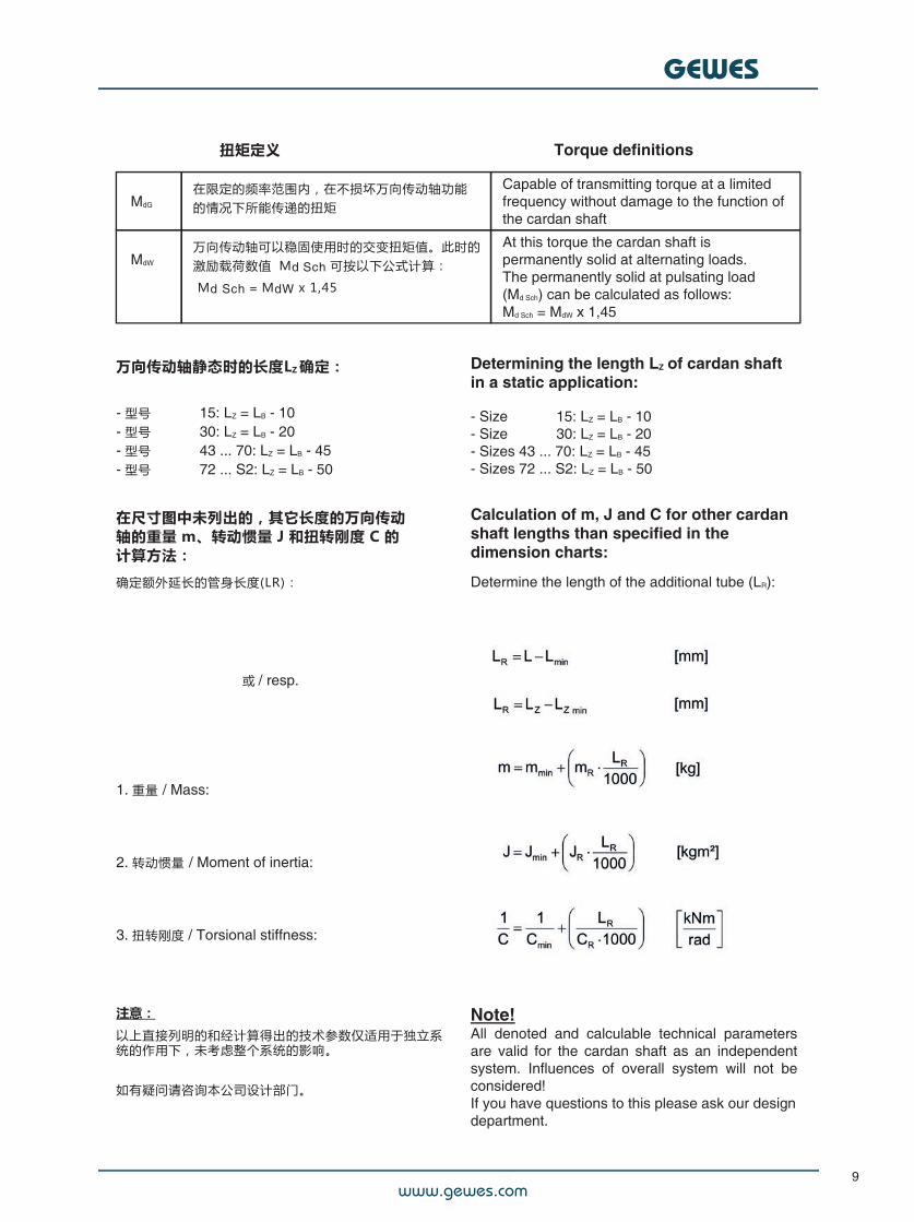
#扭矩定义 Torque definitions
#MdG
#
在限定的频率范围内,在不损坏万向传动轴功能的情况下所能传递的扭矩
Capable of transmitting torque at a limitedfrequency without damage to the function ofthe cardan shaft
#MdW
###
万向传动轴可以稳固使用时的交变扭矩值。此时的激励载荷数值 Md Sch 可按以下公式计算:
Md Sch = MdW x 1,45
At this torque the cardan shaft ispermanently solid at alternating loads.The permanently solid at pulsating load(Md Sch) can be calculated as follows:Md Sch = MdW x 1,45
万向传动轴静态时的长度LZ 确定:
- 型号 ##### 15: LZ = LB - 10- 型号 ##### 30: LZ = LB - 20- 型号 ##### 43 ... 70: LZ = LB - 45- 型号 ##### 72 ... S2: LZ = LB - 50
Determining the length LZ of cardan shaftin a static application:
- Size ##### 15: LZ = LB - 10- Size ##### 30: LZ = LB - 20- Sizes 43 ... 70: LZ = LB - 45- Sizes 72 ... S2: LZ = LB - 50
在尺寸图中未列出的,其它长度的万向传动轴的重量 m、转动惯量 J 和扭转刚度 C 的计算方法:
Calculation of m, J and C for other cardanshaft lengths than specified in thedimension charts:
确定额外延长的管身长度(LR):#
Determine the length of the additional tube (LR):
或 / resp.
1. 重量 / Mass:
2. 转动惯量 / Moment of inertia:
3. 扭转刚度 / Torsional stiffness:
Note!All denoted and calculable technical parametersare valid for the cardan shaft as an independentsystem. Influences of overall system will not beconsidered!If you have questions to this please ask our designdepartment.
注意:
以上直接列明的和经计算得出的技术参数仅适用于独立系统的作用下,未考虑整个系统的影响。
如有疑问请咨询本公司设计部门。
www.gewes.com
GEWES
10
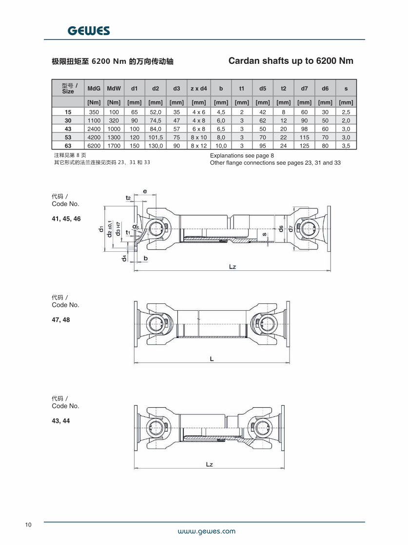
极限扭矩至 6200 Nm 的万向传动轴#
Cardan shafts up to 6200 Nm
型号 /Size MdG MdW d1 d2 d3 z x d4 b t1 d5 t2 d7 d6 s
[Nm] [Nm] [mm] [mm] [mm] [mm] [mm] [mm] [mm] [mm] [mm] [mm] [mm]
15 350 100 65 52,0 35 4 x 6 4,5 2 42 8 60 30 2,530 1100 320 90 74,5 47 4 x 8 6,0 3 62 12 90 50 2,043 2400 1000 100 84,0 57 6 x 8 6,5 3 50 20 98 60 3,053 4200 1300 120 101,5 75 8 x 10 8,0 3 70 22 115 70 3,063 6200 1700 150 130,0 90 8 x 12 10,0 3 95 24 125 80 3,5
注释见第 8 页其它形式的法兰连接见页码 23、31 和 33
Explanations see page 8Other flange connections see pages 23, 31 and 33
代码 /Code No.
41, 45, 46
代码 /Code No.
47, 48
代码 /Code No.
43, 44
www.gewes.com
GEWES
11
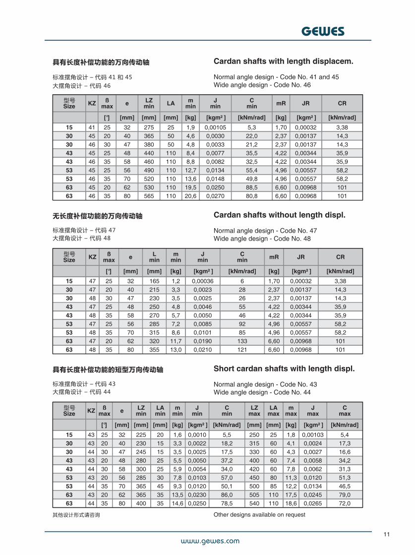
具有长度补偿功能的万向传动轴
标准摆角设计 – 代码 41 和 45大摆角设计 – 代码 46
Cardan shafts with length displacem.
Normal angle design - Code No. 41 and 45Wide angle design - Code No. 46
型号Size KZ ß
max e LZmin LA m
minJ
minC
min mR JR CR
[°] [mm] [mm] [mm] [kg] [kgm² ] [kNm/rad] [kg] [kgm² ] [kNm/rad]
15 41 25 32 275 25 1,9 0,00105 5,3 1,70 0,00032 3,3830 45 20 40 365 50 4,6 0,0030 22,0 2,37 0,00137 14,330 46 30 47 380 50 4,8 0,0033 21,2 2,37 0,00137 14,343 45 25 48 440 110 8,4 0,0077 35,5 4,22 0,00344 35,943 46 35 58 460 110 8,8 0,0082 32,5 4,22 0,00344 35,953 45 25 56 490 110 12,7 0,0134 55,4 4,96 0,00557 58,253 46 35 70 520 110 13,6 0,0148 49,8 4,96 0,00557 58,263 45 20 62 530 110 19,5 0,0250 88,5 6,60 0,00968 10163 46 35 80 565 110 20,6 0,0270 80,8 6,60 0,00968 101
无长度补偿功能的万向传动轴
标准摆角设计 – 代码 47大摆角设计 – 代码 48
Cardan shafts without length displ.
Normal angle design - Code No. 47Wide angle design - Code No. 48
型号Size KZ ß
max e Lmin
mmin
Jmin
Cmin mR JR CR
[°] [mm] [mm] [kg] [kgm² ] [kNm/rad] [kg] [kgm² ] [kNm/rad]
15 47 25 32 165 1,2 0,00036 6 1,70 0,00032 3,3830 47 20 40 215 3,3 0,0023 28 2,37 0,00137 14,330 48 30 47 230 3,5 0,0025 26 2,37 0,00137 14,343 47 25 48 250 4,8 0,0046 55 4,22 0,00344 35,943 48 35 58 270 5,7 0,0050 46 4,22 0,00344 35,953 47 25 56 285 7,2 0,0085 92 4,96 0,00557 58,253 48 35 70 315 8,6 0,0101 85 4,96 0,00557 58,263 47 20 62 320 11,7 0,0190 133 6,60 0,00968 10163 48 35 80 355 13,0 0,0210 121 6,60 0,00968 101
具有长度补偿功能的短型万向传动轴
标准摆角设计 – 代码 43大摆角设计 – 代码 44
Short cardan shafts with length displ.
Normal angle design - Code No. 43Wide angle design - Code No. 44
型号Size KZ ß
max e LZmin
LAmin
mmin
Jmin
Cmin
LZmax
LAmax
mmax
Jmax
Cmax
[°] [mm] [mm] [mm] [kg] [kgm² ] [kNm/rad] [mm] [mm] [kg] [kgm² ] [kNm/rad]
15 43 25 32 225 20 1,6 0,0010 5,5 250 25 1,8 0,00103 5,430 43 20 40 230 15 3,3 0,0022 18,2 315 60 4,1 0,0024 17,330 44 30 47 245 15 3,5 0,0025 17,5 330 60 4,3 0,0027 16,643 43 20 48 280 25 5,5 0,0050 37,2 400 60 7,4 0,0058 34,243 44 30 58 300 25 5,9 0,0054 34,0 420 60 7,8 0,0062 31,353 43 20 56 285 30 7,8 0,0103 57,0 450 80 11,3 0,0120 51,353 44 35 70 365 45 9,3 0,0120 50,1 500 85 12,2 0,0134 46,563 43 20 62 365 35 13,5 0,0230 86,0 505 110 17,5 0,0245 79,063 44 35 80 400 35 14,6 0,0250 78,5 540 110 18,6 0,0265 72,0
其他设计形式请咨询 Other designs available on request
www.gewes.com
GEWES
12
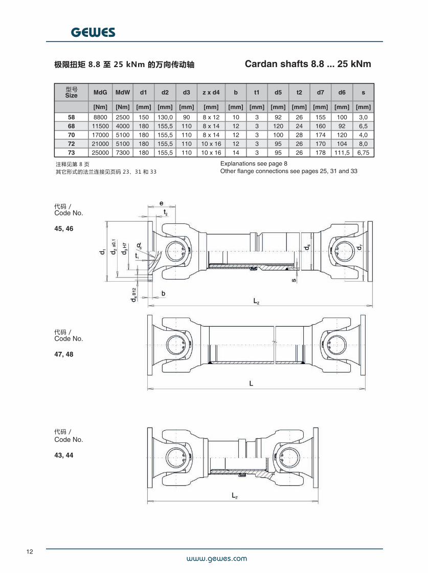
极限扭矩 8.8 至 25 kNm 的万向传动轴#
Cardan shafts 8.8 ... 25 kNm
型号Size MdG MdW d1 d2 d3 z x d4 b t1 d5 t2 d7 d6 s
[Nm] [Nm] [mm] [mm] [mm] [mm] [mm] [mm] [mm] [mm] [mm] [mm] [mm]
58 8800 2500 150 130,0 90 8 x 12 10 3 92 26 155 100 3,068 11500 4000 180 155,5 110 8 x 14 12 3 120 24 160 92 6,570 17000 5100 180 155,5 110 8 x 14 12 3 100 28 174 120 4,072 21000 5100 180 155,5 110 10 x 16 12 3 95 26 170 104 8,073 25000 7300 180 155,5 110 10 x 16 14 3 95 26 178 111,5 6,75
Explanations see page 8Other flange connections see pages 25, 31 and 33
代码 /Code No.
45, 46
代码 /Code No.
47, 48
代码 /Code No.
43, 44
注释见第 8 页其它形式的法兰连接见页码 23、31 和 33
www.gewes.com
GEWES
13
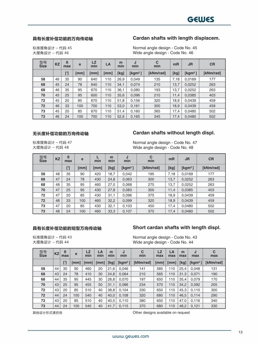
具有长度补偿功能的万向传动轴
标准摆角设计 – 代码 45大摆角设计 – 代码 46
Cardan shafts with length displacem.
Normal angle design - Code No. 45Wide angle design - Code No. 46
型号Size KZ ß
max e LZmin LA m
minJ
minC
min mR JR CR
[°] [mm] [mm] [mm] [kg] [kgm² ] [kNm/rad] [kg] [kgm² ] [kNm/rad]
58 46 35 90 640 110 26,9 0,049 135 7,18 0,0169 17768 45 24 78 640 110 34,1 0,074 210 13,7 0,0252 26368 46 35 95 670 110 36,1 0,080 193 13,7 0,0252 26370 45 25 95 600 110 35,6 0,096 210 11,4 0,0385 40372 45 20 85 670 110 51,8 0,156 320 18,9 0,0439 45972 46 33 100 700 110 53,0 0,161 300 18,9 0,0439 45973 45 20 85 670 110 51,4 0,160 365 17,4 0,0480 50273 46 24 100 700 110 52,6 0,165 345 17,4 0,0480 502
无长度补偿功能的万向传动轴
标准摆角设计 – 代码 47大摆角设计 – 代码 48
Cardan shafts without length displ.
Normal angle design - Code No. 47Wide angle design - Code No. 48
型号Size KZ ß
max e Lmin
mmin
Jmin
Cmin mR JR CR
[°] [mm] [mm] [kg] [kgm² ] [kNm/rad] [kg] [kgm² ] [kNm/rad]
58 48 35 90 420 18,7 0,042 195 7,18 0,0169 17768 47 24 78 430 24,8 0,063 300 13,7 0,0252 26368 48 35 95 460 27,0 0,068 275 13,7 0,0252 26370 47 25 95 430 27,8 0,083 300 11,4 0,0385 40372 47 20 85 430 31,1 0,096 375 18,9 0,0439 45972 48 33 100 460 32,2 0,099 320 18,9 0,0439 45973 47 20 85 430 32,1 0,103 450 17,4 0,0480 50273 48 24 100 460 33,3 0,107 375 17,4 0,0480 502
具有长度补偿功能的短型万向传动轴
标准摆角设计 – 代码 43大摆角设计 – 代码 44
Short cardan shafts with length displ.
Normal angle design - Code No. 43Wide angle design - Code No. 44
型号Size KZ ß
max e LZmin
LAmin
mmin
Jmin
Cmin
LZmax
LAmax
mmax
Jmax
Cmax
[°] [mm] [mm] [mm] [kg] [kgm² ] [kNm/rad] [mm] [mm] [kg] [kgm² ] [kNm/rad]
58 44 30 90 460 20 21,6 0,046 141 585 110 25,4 0,048 13168 43 24 78 410 30 24,8 0,064 210 565 110 31,3 0,071 19068 44 35 95 445 30 26,8 0,070 197 650 110 35,4 0,079 17070 43 25 95 455 50 31,1 0,086 234 570 110 34,2 0,092 20572 43 20 85 510 40 38,8 0,104 330 650 110 45,3 0,110 30072 44 24 100 540 40 40,0 0,108 320 680 110 46,5 0,114 29073 43 20 85 510 40 40,5 0,110 380 650 110 47,0 0,116 34073 44 24 100 540 40 41,7 0,115 370 680 110 48,2 0,121 330
其他设计形式请咨询 Other designs available on request
www.gewes.com
GEWES
14
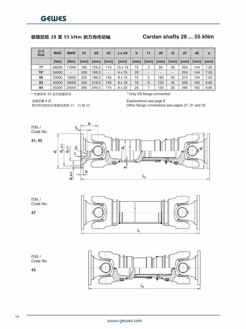
极限扭矩 28 至 55 kNm 的万向传动轴#
Cardan shafts 28 ... 55 kNm
型号Size MdG MdW d1 d2 d3 z x d4 b t1 d5 t2 d7 d6 s
[Nm] [Nm] [mm] [mm] [mm] [mm] [mm] [mm] [mm] [mm] [mm] [mm] [mm]
77 28000 11000 180 155,5 110 10 x 16 15 3 95 30 204 144 7,0079* 34000 - 200 165,0 - 4 x 15 20 - - - 204 144 7,0080 33000 13000 225 196,0 140 8 x 16 15 5 160 30 215 144 7,0083 40000 18000 250 218,0 140 8 x 18 18 6 120 45 250 162 9,8584 55000 23000 285 245,0 175 8 x 20 20 7 130 35 265 162 9,85
* 代表仅有 XS 法兰连接形式 * Only XS flange connection
Explanations see page 8Other flange connections see pages 27, 31 and 33
代码 /Code No.
41, 45
代码 /Code No.
47
代码 /Code No.
43
注释见第 8 页其它形式的法兰连接见页码 27、31 和 33
www.gewes.com
GEWES
15
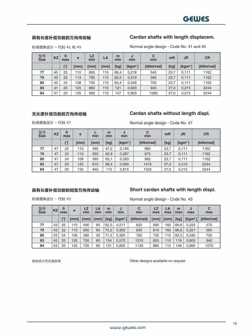
具有长度补偿功能的万向传动轴
标准摆角设计 – 代码 41 和 45
Cardan shafts with length displacem.
Normal angle design - Code No. 41 and 45
型号Size KZ ß
max e LZmin LA m
minJ
minC
min mR JR CR
[°] [mm] [mm] [mm] [kg] [kgm² ] [kNm/rad] [kg] [kgm² ] [kNm/rad]
77 45 25 110 695 110 68,4 0,218 545 23,7 0,111 116279 45 22 113 785 110 82,0 0,319 565 23,7 0,111 116280 45 24 108 735 110 84,4 0,348 705 23,7 0,111 116283 41 20 125 860 110 121 0,620 945 37,0 0,215 224484 41 20 135 900 110 147 0,903 1060 37,0 0,215 2244
无长度补偿功能的万向传动轴
标准摆角设计 – 代码 47
Cardan shafts without length displ.
Normal angle design - Code No. 47
型号Size KZ ß
max e Lmin
mmin
Jmin
Cmin mR JR CR
[°] [mm] [mm] [kg] [kgm² ] [kNm/rad] [kg] [kgm² ] [kNm/rad]
77 47 25 110 495 47,2 0,195 680 23,7 0,111 116279 47 22 113 555 62,8 0,287 670 23,7 0,111 116280 47 24 108 560 65,1 0,320 965 23,7 0,111 116283 47 20 125 610 88,4 0,560 1415 37,0 0,215 224484 47 20 135 640 115 0,815 1525 37,0 0,215 2244
具有长度补偿功能的短型万向传动轴
标准摆角设计 – 代码 43
Short cardan shafts with length displ.
Normal angle design - Code No. 43
型号Size KZ ß
max e LZmin
LAmin
mmin
Jmin
Cmin
LZmax
LAmax
mmax
Jmax
Cmax
[°] [mm] [mm] [mm] [kg] [kgm² ] [kNm/rad] [mm] [mm] [kg] [kgm² ] [kNm/rad]
77 43 25 110 590 60 62,5 0,211 620 690 160 69,8 0,223 57079 43 22 113 650 95 75,2 0,302 630 810 160 86,6 0,321 56080 43 24 108 560 30 71,2 0,320 785 730 110 82,5 0,340 72083 43 20 125 700 60 104 0,570 1010 855 110 119 0,605 94084 43 20 135 735 60 131 0,825 1130 895 110 146 0,860 1070
其他设计形式请咨询 Other designs available on request
www.gewes.com
GEWES
16
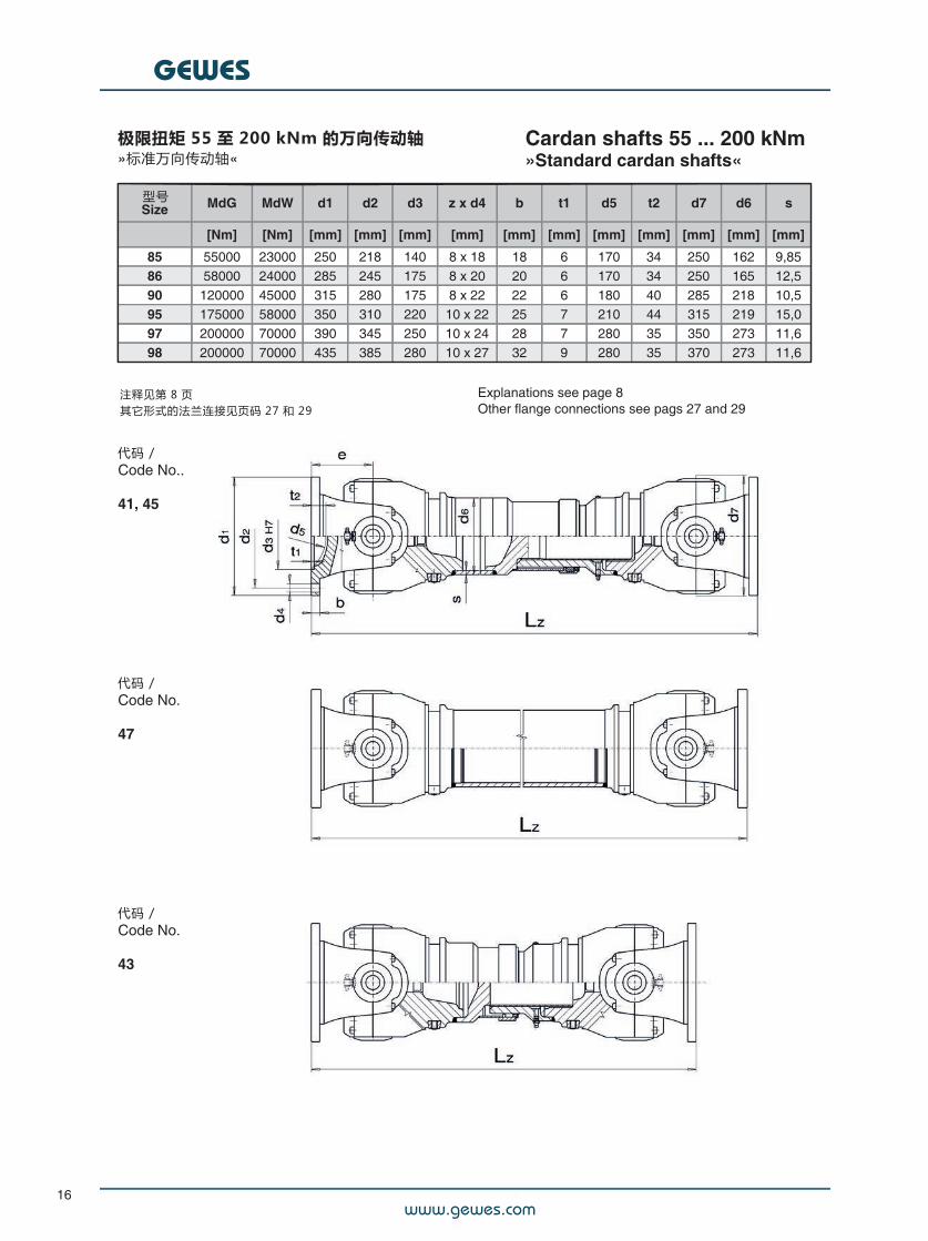
极限扭矩 55 至 200 kNm 的万向传动轴»标准万向传动轴«
Cardan shafts 55 ... 200 kNm»Standard cardan shafts«
型号Size MdG MdW d1 d2 d3 z x d4 b t1 d5 t2 d7 d6 s
[Nm] [Nm] [mm] [mm] [mm] [mm] [mm] [mm] [mm] [mm] [mm] [mm] [mm]
85 55000 23000 250 218 140 8 x 18 18 6 170 34 250 162 9,8586 58000 24000 285 245 175 8 x 20 20 6 170 34 250 165 12,590 120000 45000 315 280 175 8 x 22 22 6 180 40 285 218 10,595 175000 58000 350 310 220 10 x 22 25 7 210 44 315 219 15,097 200000 70000 390 345 250 10 x 24 28 7 280 35 350 273 11,698 200000 70000 435 385 280 10 x 27 32 9 280 35 370 273 11,6
Explanations see page 8Other flange connections see pags 27 and 29
代码 /Code No..
41, 45
代码 /Code No.
47
代码 /Code No.
43
注释见第 8 页其它形式的法兰连接见页码 27 和 29
www.gewes.com
GEWES
17
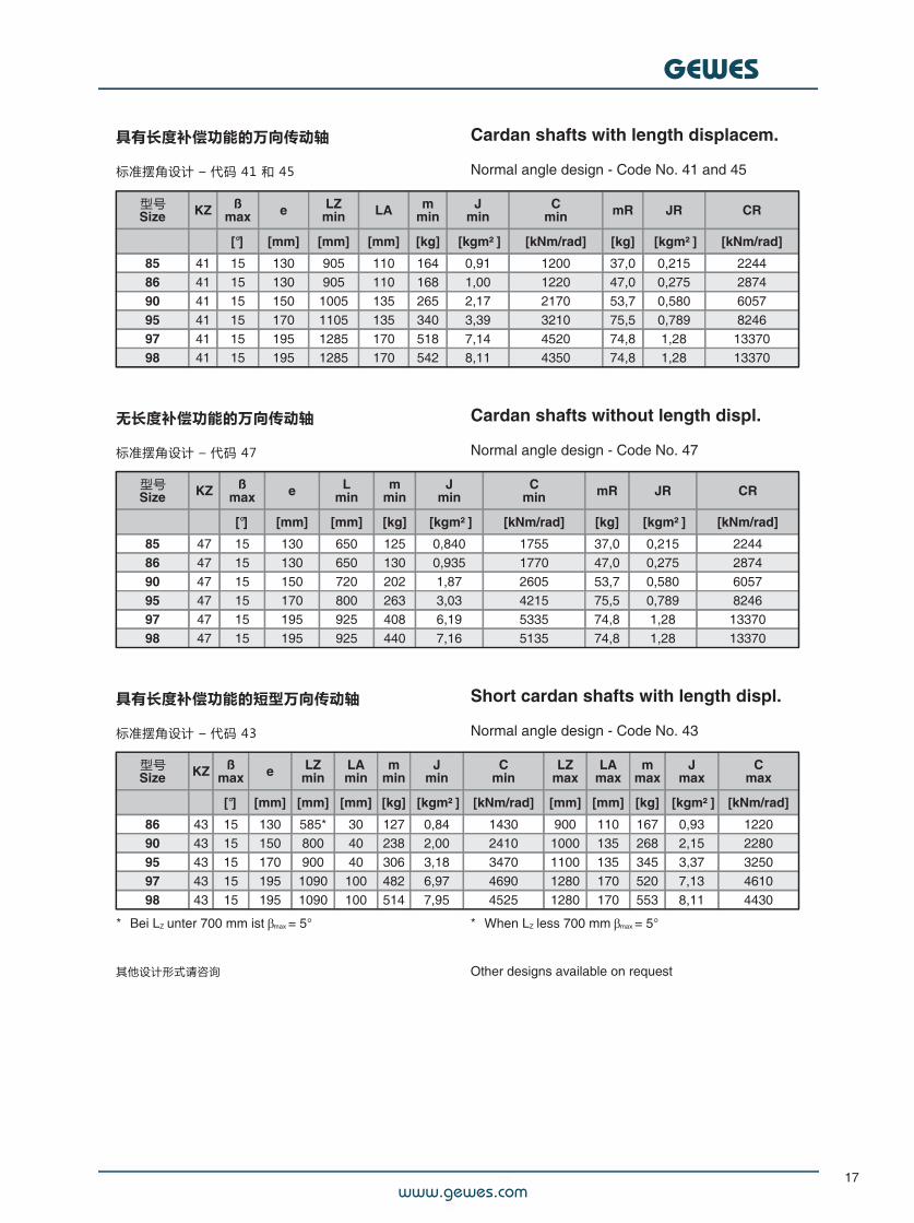
具有长度补偿功能的万向传动轴
标准摆角设计 – 代码 41 和 45
Cardan shafts with length displacem.
Normal angle design - Code No. 41 and 45
型号Size KZ ß
max e LZmin LA m
minJ
minC
min mR JR CR
[°] [mm] [mm] [mm] [kg] [kgm² ] [kNm/rad] [kg] [kgm² ] [kNm/rad]
85 41 15 130 905 110 164 0,91 1200 37,0 0,215 224486 41 15 130 905 110 168 1,00 1220 47,0 0,275 287490 41 15 150 1005 135 265 2,17 2170 53,7 0,580 605795 41 15 170 1105 135 340 3,39 3210 75,5 0,789 824697 41 15 195 1285 170 518 7,14 4520 74,8 1,28 1337098 41 15 195 1285 170 542 8,11 4350 74,8 1,28 13370
无长度补偿功能的万向传动轴
标准摆角设计 – 代码 47
Cardan shafts without length displ.
Normal angle design - Code No. 47
型号Size KZ ß
max e Lmin
mmin
Jmin
Cmin mR JR CR
[°] [mm] [mm] [kg] [kgm² ] [kNm/rad] [kg] [kgm² ] [kNm/rad]
85 47 15 130 650 125 0,840 1755 37,0 0,215 224486 47 15 130 650 130 0,935 1770 47,0 0,275 287490 47 15 150 720 202 1,87 2605 53,7 0,580 605795 47 15 170 800 263 3,03 4215 75,5 0,789 824697 47 15 195 925 408 6,19 5335 74,8 1,28 1337098 47 15 195 925 440 7,16 5135 74,8 1,28 13370
具有长度补偿功能的短型万向传动轴
标准摆角设计 – 代码 43
Short cardan shafts with length displ.
Normal angle design - Code No. 43
型号Size KZ ß
max e LZmin
LAmin
mmin
Jmin
Cmin
LZmax
LAmax
mmax
Jmax
Cmax
[°] [mm] [mm] [mm] [kg] [kgm² ] [kNm/rad] [mm] [mm] [kg] [kgm² ] [kNm/rad]
86 43 15 130 585* 30 127 0,84 1430 900 110 167 0,93 122090 43 15 150 800 40 238 2,00 2410 1000 135 268 2,15 228095 43 15 170 900 40 306 3,18 3470 1100 135 345 3,37 325097 43 15 195 1090 100 482 6,97 4690 1280 170 520 7,13 461098 43 15 195 1090 100 514 7,95 4525 1280 170 553 8,11 4430
** Bei LZ unter 700 mm ist max = 5°
其他设计形式请咨询
** When LZ less 700 mm max = 5°
Other designs available on request
www.gewes.com
GEWES
18
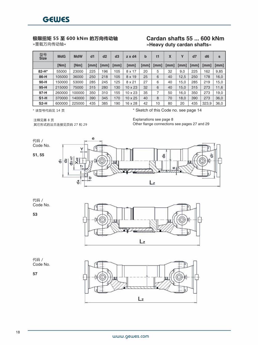
极限扭矩 55 至 600 kNm 的万向传动轴»重载万向传动轴«
Cardan shafts 55 ... 600 kNm»Heavy duty cardan shafts«
型号Size MdG MdW d1 d2 d3 z x d4 b t1 X Y d7 d6 s
[Nm] [Nm] [mm] [mm] [mm] [mm] [mm] [mm] [mm] [mm] [mm] [mm] [mm]
82-H* 55000 23000 225 196 105 8 x 17 20 5 32 9,0 225 162 9,8586-H 105000 36000 250 218 105 8 x 19 25 6 40 12,5 250 178 16,090-H 150000 53000 285 245 125 8 x 21 27 6 40 15,0 285 219 15,095-H 215000 75000 315 280 130 10 x 23 32 6 40 15,0 315 273 11,697-H 260000 100000 350 310 155 10 x 23 35 7 50 16,0 350 273 19,0S1-H 370000 140000 390 345 170 10 x 25 40 8 70 18,0 390 273 36,0S2-H 600000 225000 435 385 190 16 x 28 42 10 80 20 435 323,9 36,0
* 该型号代码见 14 页 * Sketch of this Code no. see page 14
Explanations see page 8Other flange connections see pages 27 and 29
代码 /Code No.
51, 55
代码 /Code No.
53
代码 /Code No.
57
注释见第 8 页其它形式的法兰连接见页码 27 和 29
www.gewes.com
GEWES
19
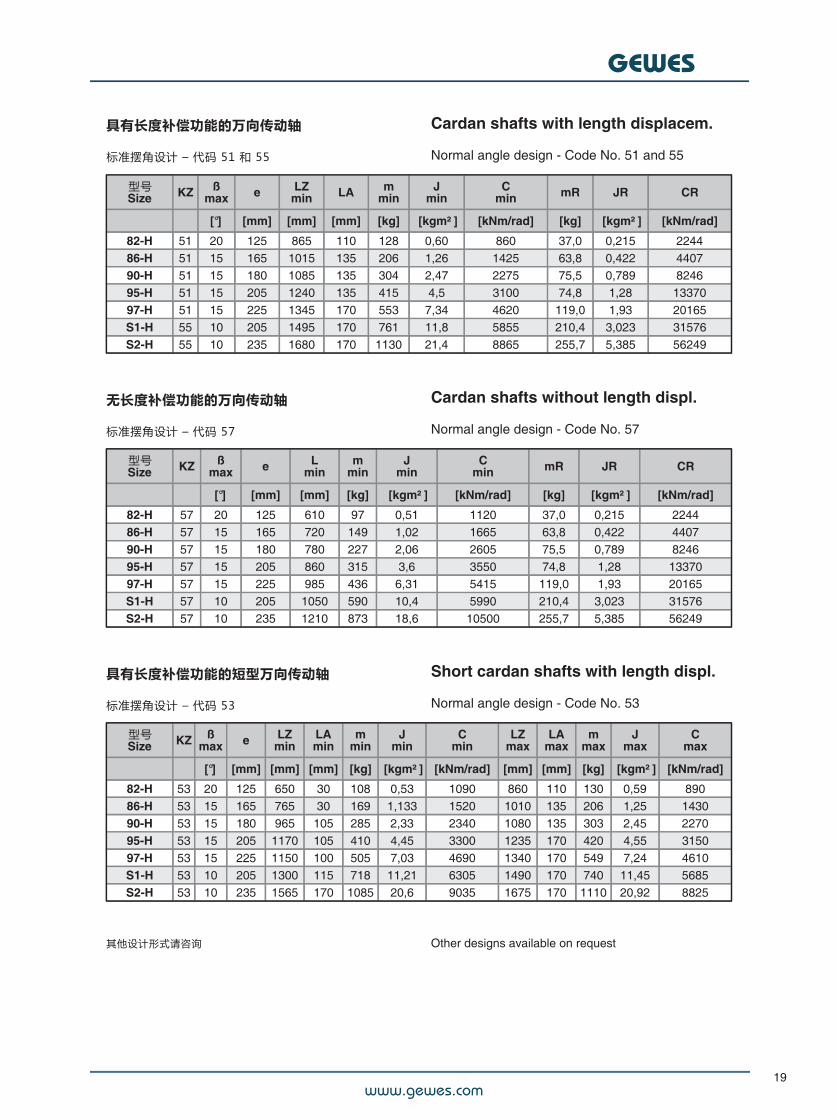
具有长度补偿功能的万向传动轴
标准摆角设计 – 代码 51 和 55
Cardan shafts with length displacem.
Normal angle design - Code No. 51 and 55
型号Size KZ ß
max e LZmin LA m
minJ
minC
min mR JR CR
[°] [mm] [mm] [mm] [kg] [kgm² ] [kNm/rad] [kg] [kgm² ] [kNm/rad]
82-H 51 20 125 865 110 128 0,60 860 37,0 0,215 224486-H 51 15 165 1015 135 206 1,26 1425 63,8 0,422 440790-H 51 15 180 1085 135 304 2,47 2275 75,5 0,789 824695-H 51 15 205 1240 135 415 4,5 3100 74,8 1,28 1337097-H 51 15 225 1345 170 553 7,34 4620 119,0 1,93 20165S1-H 55 10 205 1495 170 761 11,8 5855 210,4 3,023 31576S2-H 55 10 235 1680 170 1130 21,4 8865 255,7 5,385 56249
无长度补偿功能的万向传动轴
标准摆角设计 – 代码 57
Cardan shafts without length displ.
Normal angle design - Code No. 57
型号Size KZ ß
max e Lmin
mmin
Jmin
Cmin mR JR CR
[°] [mm] [mm] [kg] [kgm² ] [kNm/rad] [kg] [kgm² ] [kNm/rad]
82-H 57 20 125 610 97 0,51 1120 37,0 0,215 224486-H 57 15 165 720 149 1,02 1665 63,8 0,422 440790-H 57 15 180 780 227 2,06 2605 75,5 0,789 824695-H 57 15 205 860 315 3,6 3550 74,8 1,28 1337097-H 57 15 225 985 436 6,31 5415 119,0 1,93 20165S1-H 57 10 205 1050 590 10,4 5990 210,4 3,023 31576S2-H 57 10 235 1210 873 18,6 10500 255,7 5,385 56249
具有长度补偿功能的短型万向传动轴
标准摆角设计 – 代码 53
Short cardan shafts with length displ.
Normal angle design - Code No. 53
型号Size KZ ß
max e LZmin
LAmin
mmin
Jmin
Cmin
LZmax
LAmax
mmax
Jmax
Cmax
[°] [mm] [mm] [mm] [kg] [kgm² ] [kNm/rad] [mm] [mm] [kg] [kgm² ] [kNm/rad]
82-H 53 20 125 650 30 108 0,53 1090 860 110 130 0,59 89086-H 53 15 165 765 30 169 1,133 1520 1010 135 206 1,25 143090-H 53 15 180 965 105 285 2,33 2340 1080 135 303 2,45 227095-H 53 15 205 1170 105 410 4,45 3300 1235 170 420 4,55 315097-H 53 15 225 1150 100 505 7,03 4690 1340 170 549 7,24 4610S1-H 53 10 205 1300 115 718 11,21 6305 1490 170 740 11,45 5685S2-H 53 10 235 1565 170 1085 20,6 9035 1675 170 1110 20,92 8825
其他设计形式请咨询 Other designs available on request
www.gewes.com
GEWES
20
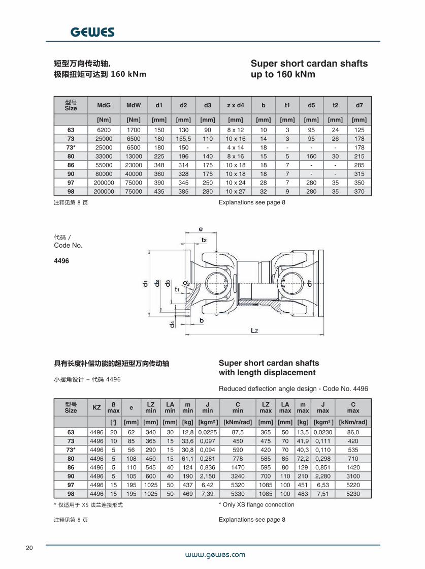
短型万向传动轴,极限扭矩可达到 160 kNm
Super short cardan shaftsup to 160 kNm
型号Size MdG MdW d1 d2 d3 z x d4 b t1 d5 t2 d7
[Nm] [Nm] [mm] [mm] [mm] [mm] [mm] [mm] [mm] [mm] [mm]
63 6200 1700 150 130 90 8 x 12 10 3 95 24 12573 25000 6500 180 155,5 110 10 x 16 14 3 95 26 17873* 25000 6500 180 150 - 4 x 14 18 - - - 17880 33000 13000 225 196 140 8 x 16 15 5 160 30 21586 55000 23000 348 314 175 10 x 18 18 7 - - 28590 80000 40000 360 328 175 10 x 18 18 7 - - 31597 200000 75000 390 345 250 10 x 24 28 7 280 35 35098 200000 75000 435 385 280 10 x 27 32 9 280 35 370
注释见第 8 页 Explanations see page 8
具有长度补偿功能的超短型万向传动轴
小摆角设计 – 代码 4496
Super short cardan shaftswith length displacement
Reduced deflection angle design - Code No. 4496
型号Size KZ ß
max e LZmin
LAmin
mmin
Jmin
Cmin
LZmax
LAmax
mmax
Jmax
Cmax
[°] [mm] [mm] [mm] [kg] [kgm² ] [kNm/rad] [mm] [mm] [kg] [kgm² ] [kNm/rad]
63 4496 20 62 340 30 12,8 0,0225 87,5 365 50 13,5 0,0230 86,073 4496 10 85 365 15 33,6 0,097 450 475 70 41,9 0,111 42073* 4496 5 56 290 15 30,8 0,094 590 420 70 40,3 0,110 53580 4496 5 108 450 15 61,1 0,281 778 585 85 72,2 0,298 71086 4496 5 110 545 40 124 0,836 1470 595 80 129 0,851 142090 4496 5 105 600 40 190 2,150 3240 700 110 210 2,280 310097 4496 15 195 1025 50 437 6,42 5320 1085 100 451 6,53 522098 4496 15 195 1025 50 469 7,39 5330 1085 100 483 7,51 5230
* 仅适用于 XS 法兰连接形式
注释见第 8 页
* Only XS flange connection
Explanations see page 8
代码 /Code No.
4496
www.gewes.com
GEWES
21
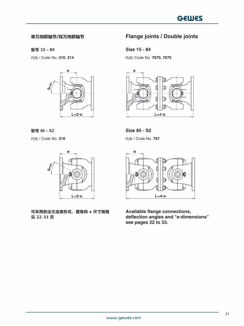
单万向联轴节/双万向联轴节 Flange joints / Double joints
型号 15 – 84 Size 15 - 84
代码 / Code No. 310, 314 代码/ Code No. 7670, 7675
型号 85 – S2 Size 85 - S2
代码 / Code No. 310 代码 / Code No. 767
可采用的法兰连接形式、摆角和 e 尺寸规格见 22-33 页
Available flange connections,deflection angles and "e-dimensions"see pages 22 to 33.
www.gewes.com
GEWES
22
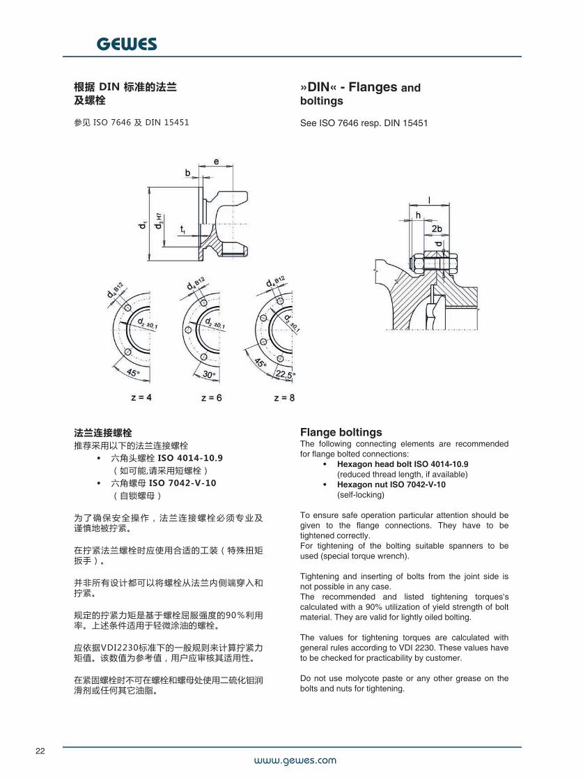
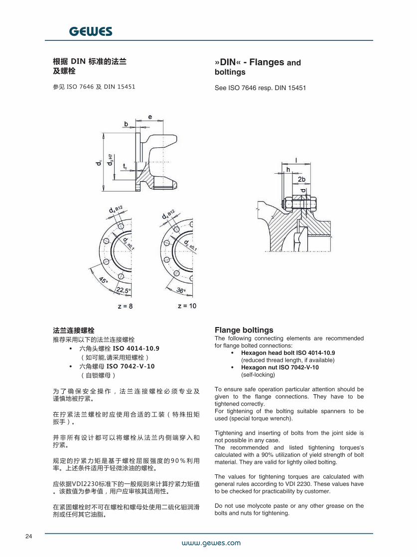
根据 DIN 标准的法兰及螺栓
参见 ISO 7646 及 DIN 15451
»DIN« - Flanges andboltings
See ISO 7646 resp. DIN 15451
法兰连接螺栓推荐采用以下的法兰连接螺栓
• 六角头螺栓 ISO 4014-10.9(如可能,请采用短螺栓)
• 六角螺母 ISO 7042-V-10(自锁螺母)
为 了 确 保 安 全 操 作 , 法 兰 连 接 螺 栓 必 须 专 业 及谨慎地被拧紧。
在拧紧法兰螺栓时应使用合适的工装(特殊扭矩扳手)。
并非所有设计都可以将螺栓从法兰内侧端穿入和拧紧。
规定的拧紧力矩是基于螺栓屈服强度的90%利用率。上述条件适用于轻微涂油的螺栓。
应依据VDI2230标准下的一般规则来计算拧紧力矩值。该数值为参考值,用户应审核其适用性。
在紧固螺栓时不可在螺栓和螺母处使用二硫化钼润滑剂或任何其它油脂。
Flange boltingsThe following connecting elements are recommendedfor flange bolted connections:
• Hexagon head bolt ISO 4014-10.9(reduced thread length, if available)
• Hexagon nut ISO 7042-V-10(self-locking)
#To ensure safe operation particular attention should begiven to the flange connections. They have to betightened correctly.For tightening of the bolting suitable spanners to beused (special torque wrench).
Tightening and inserting of bolts from the joint side isnot possible in any case.The recommended and listed tightening torques'scalculated with a 90% utilization of yield strength of boltmaterial. They are valid for lightly oiled bolting.
The values for tightening torques are calculated withgeneral rules according to VDI 2230. These values haveto be checked for practicability by customer.
Do not use molycote paste or any other grease on thebolts and nuts for tightening.
www.gewes.com
GEWES
23
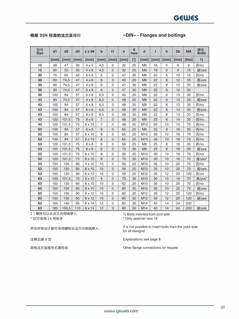
根据 DIN 标准的法兰及螺栓# »DIN« - Flanges and boltings
型号Size d1 d2 d3 z x d4 b t1 e ß
max d l h 2b MA
[mm] [mm] [mm] [mm] [mm] [mm] [mm] [°] [mm] [mm] [mm] [mm] [Nm] 1)
15 58 47 30 4 x 5 4,5 2 32 25 M5 16 5 9 9 否/no15 65 52 35 4 x 6 4,5 2 32 25 M6 16 6 9 15 是/yes30 75 62 42 6 x 6 5 2 47 30 M6 20 6 10 15 否/no30 90 74,5 47 4 x 8 6 3 40 20 M8 22 8 12 35 是/yes30 90 74,5 47 4 x 8 6 3 47 30 M8 22 8 12 35 是/yes30 90 74,5 47 6 x 8 6 3 47 30 M8 22 8 12 3530 100 84 57 6 x 8 6,5 3 40 20 M8 22 8 13 35 否/no43 90 74,5 47 4 x 8 6,5 3 48 25 M8 22 8 13 35 是/yes43 100 84 57 6 x 8 6,5 3 48 25 M8 22 8 13 35 否/no43 100 84 57 6 x 8 6,5 3 58 35 M8 22 8 13 35 是/yes43 100 84 57 8 x 8 6,5 3 58 35 M8 22 8 13 35 否/no43 120 101,5 75 8 x 8 7 3 48 25 M8 25 8 14 35 否/no43 120 101,5 75 8 x 10 7 3 48 25 M10 25 10 14 70 否/no53 100 84 57 6 x 8 8 3 65 25 M8 25 8 16 35 否/no53 100 84 57 6 x 10 8 3 65 25 M10 30 10 16 70 否/no53 100 84 57 8 x 10 8 3 65 25 M10 30 10 16 70 否/no53 120 101,5 75 8 x 8 8 3 56 25 M8 25 8 16 35 否/no53 120 101,5 75 8 x 8 8 3 70 35 M8 25 8 16 35 是/yes53 120 101,5 75 8 x 10 8 3 56 25 M10 30 10 16 70 否/no53 120 101,5 75 8 x 10 8 3 70 35 M10 30 10 16 70 是/yes*53 150 130 90 4 x 10 10 3 56 25 M10 35 10 20 70 否/no53 150 130 90 8 x 10 10 3 56 25 M10 35 10 20 70 是/yes53 150 130 90 8 x 12 10 3 56 25 M12 35 12 20 120 否/no63 120 101,5 75 8 x 10 8 3 75 35 M10 30 10 16 70 是/yes*63 150 130 90 8 x 10 10 3 62 20 M10 35 10 20 70 否/no63 150 130 90 8 x 10 10 3 80 35 M10 35 10 20 70 是/yes63 150 130 90 8 x 12 10 3 62 20 M12 35 12 20 120 否/no63 150 130 90 8 x 12 10 3 80 35 M12 35 12 20 120 是/yes63 165 140 95 8 x 14 12 3 80 30 M14 40 14 24 20063 180 155,5 110 8 x 14 12 3 80 30 M14 40 14 24 200 是/yes
1)螺栓可以从法兰内侧端穿入* 仅可采用 16 号扳手
并非所有设计都可采用螺栓从法兰内侧端穿入
注释见第 8 页
其他法兰连接形式请咨询
1) Bolts inserted from joint side* Only spanner size 16
It is not possible to insert bolts from the yoke sidefor all designs!
Explanations see page 8
Other flange connections on request
螺栓Bolts
www.gewes.com
GEWES
24
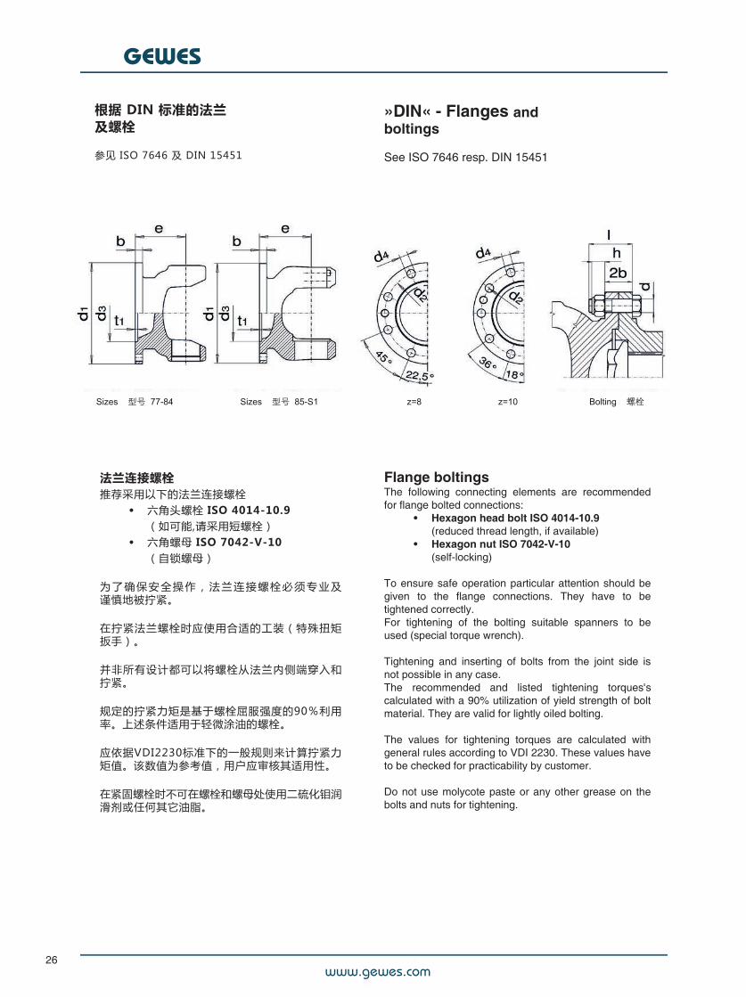
根据 DIN 标准的法兰及螺栓
参见 ISO 7646 及 DIN 15451
»DIN« - Flanges andboltings
See ISO 7646 resp. DIN 15451
法兰连接螺栓推荐采用以下的法兰连接螺栓
• 六角头螺栓 ISO 4014-10.9(如可能,请采用短螺栓)
• 六角螺母 ISO 7042-V-10(自锁螺母)
为 了 确 保 安 全 操 作 , 法 兰 连 接 螺 栓 必 须 专 业 及谨慎地被拧紧。
在 拧 紧 法 兰 螺 栓 时 应 使 用 合 适 的 工 装 ( 特 殊 扭 矩扳手)。
并 非 所 有 设 计 都 可 以 将 螺 栓 从 法 兰 内 侧 端 穿 入 和拧紧。
规 定 的 拧 紧 力 矩 是 基 于 螺 栓 屈 服 强 度 的 9 0 % 利 用率。上述条件适用于轻微涂油的螺栓。
应依据VDI2230标准下的一般规则来计算拧紧力矩值。该数值为参考值,用户应审核其适用性。
在紧固螺栓时不可在螺栓和螺母处使用二硫化钼润滑剂或任何其它油脂。
Flange boltingsThe following connecting elements are recommendedfor flange bolted connections:
• Hexagon head bolt ISO 4014-10.9(reduced thread length, if available)
• Hexagon nut ISO 7042-V-10(self-locking)
#To ensure safe operation particular attention should begiven to the flange connections. They have to betightened correctly.For tightening of the bolting suitable spanners to beused (special torque wrench).
Tightening and inserting of bolts from the joint side isnot possible in any case.The recommended and listed tightening torques'scalculated with a 90% utilization of yield strength of boltmaterial. They are valid for lightly oiled bolting.
The values for tightening torques are calculated withgeneral rules according to VDI 2230. These values haveto be checked for practicability by customer.
Do not use molycote paste or any other grease on thebolts and nuts for tightening.
www.gewes.com
GEWES
25
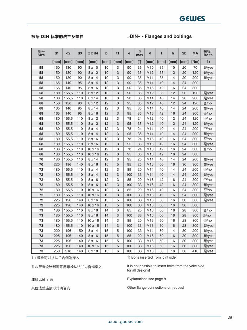
根据 DIN 标准的法兰及螺栓# »DIN« - Flanges and boltings
型号Size d1 d2 d3 z x d4 b t1 e ß
max d l h 2b MA
[mm] [mm] [mm] [mm] [mm] [mm] [mm] [°] [mm] [mm] [mm] [mm] [Nm] 1)
58 150 130 90 8 x 10 10 3 90 35 M10 35 10 20 70 是/yes58 150 130 90 8 x 12 10 3 90 35 M12 35 12 20 120 是/yes58 150 130 90 8 x 14 10 3 90 35 M14 35 14 20 200 是/yes58 165 140 95 8 x 14 12 3 90 35 M14 40 14 24 20058 165 140 95 8 x 16 12 3 90 35 M16 42 16 24 30058 180 155,5 110 8 x 12 10 3 90 35 M12 35 12 20 120 是/yes58 180 155,5 110 8 x 14 10 3 90 35 M14 40 14 20 200 是/yes68 150 130 90 8 x 12 12 3 95 35 M12 40 12 24 120 否/no68 165 140 95 8 x 14 12 3 95 35 M14 40 14 24 200 是/yes68 165 140 95 8 x 16 12 3 95 35 M16 42 16 24 300 否/no68 180 155,5 110 8 x 12 12 3 78 24 M12 40 12 24 120 否/no68 180 155,5 110 8 x 12 12 3 95 35 M12 40 12 24 120 是/yes68 180 155,5 110 8 x 14 12 3 78 24 M14 40 14 24 200 否/no68 180 155,5 110 8 x 14 12 3 95 35 M14 40 14 24 200 是/yes68 180 155,5 110 8 x 16 12 3 78 24 M16 42 16 24 300 否/no68 180 155,5 110 8 x 16 12 3 95 35 M16 42 16 24 300 是/yes68 180 155,5 110 10 x 16 12 3 78 24 M16 42 16 24 300 否/no68 180 155,5 110 10 x 16 12 3 95 35 M16 42 16 24 30070 180 155,5 110 8 x 14 12 3 95 25 M14 40 14 24 200 是/yes70 225 196 140 8 x 16 15 5 95 25 M16 50 16 30 300 是/yes72 180 155,5 110 8 x 14 12 3 85 20 M14 40 14 24 200 否/no72 180 155,5 110 8 x 14 12 3 100 33 M14 40 14 24 200 是/yes72 180 155,5 110 8 x 16 12 3 85 20 M16 42 16 24 300 否/no72 180 155,5 110 8 x 16 12 3 100 33 M16 42 16 24 300 是/yes72 180 155,5 110 10 x 16 12 3 85 20 M16 42 16 24 300 否/no72 180 155,5 110 10 x 16 12 3 100 33 M16 42 16 24 300 是/yes72 225 196 140 8 x 16 15 5 100 33 M16 50 16 30 300 是/yes72 225 196 140 10 x 16 15 5 100 33 M16 50 16 30 30073 180 155,5 110 8 x 16 14 3 85 20 M16 50 16 28 300 否/no73 180 155,5 110 8 x 16 14 3 100 33 M16 50 16 28 300 否/no73 180 155,5 110 10 x 16 14 3 85 20 M16 50 16 28 300 否/no73 180 155,5 110 10 x 16 14 3 100 33 M16 50 16 28 300 是/yes73 220 196 150 8 x 14 15 5 100 33 M14 50 14 30 200 是/yes73 225 196 140 8 x 16 15 5 85 20 M16 50 16 30 300 是/yes73 225 196 140 8 x 16 15 5 100 33 M16 50 16 30 300 是/yes73 225 196 140 10 x 16 15 5 100 33 M16 50 16 30 300 是/yes73 250 218 140 8 x 18 15 6 100 33 M18 50 18 30 410 是/yes
1)螺栓可以从法兰内侧端穿入
并非所有设计都可采用螺栓从法兰内侧端穿入
注释见第 8 页
其他法兰连接形式请咨询
1) Bolts inserted from joint side
It is not possible to insert bolts from the yoke sidefor all designs!
Explanations see page 8
Other flange connections on request
螺栓Bolts
www.gewes.com
GEWES
26
根据 DIN 标准的法兰及螺栓
参见 ISO 7646 及 DIN 15451
»DIN« - Flanges andboltings
See ISO 7646 resp. DIN 15451
法兰连接螺栓推荐采用以下的法兰连接螺栓
• 六角头螺栓 ISO 4014-10.9(如可能,请采用短螺栓)
• 六角螺母 ISO 7042-V-10(自锁螺母)
为 了 确 保 安 全 操 作 , 法 兰 连 接 螺 栓 必 须 专 业 及谨慎地被拧紧。
在拧紧法兰螺栓时应使用合适的工装(特殊扭矩扳手)。
并非所有设计都可以将螺栓从法兰内侧端穿入和拧紧。
规定的拧紧力矩是基于螺栓屈服强度的90%利用率。上述条件适用于轻微涂油的螺栓。
应依据VDI2230标准下的一般规则来计算拧紧力矩值。该数值为参考值,用户应审核其适用性。
在紧固螺栓时不可在螺栓和螺母处使用二硫化钼润滑剂或任何其它油脂。
Flange boltingsThe following connecting elements are recommendedfor flange bolted connections:
• Hexagon head bolt ISO 4014-10.9(reduced thread length, if available)
• Hexagon nut ISO 7042-V-10(self-locking)
#To ensure safe operation particular attention should begiven to the flange connections. They have to betightened correctly.For tightening of the bolting suitable spanners to beused (special torque wrench).
Tightening and inserting of bolts from the joint side isnot possible in any case.The recommended and listed tightening torques'scalculated with a 90% utilization of yield strength of boltmaterial. They are valid for lightly oiled bolting.
The values for tightening torques are calculated withgeneral rules according to VDI 2230. These values haveto be checked for practicability by customer.
Do not use molycote paste or any other grease on thebolts and nuts for tightening.
www.gewes.com
GEWES
27
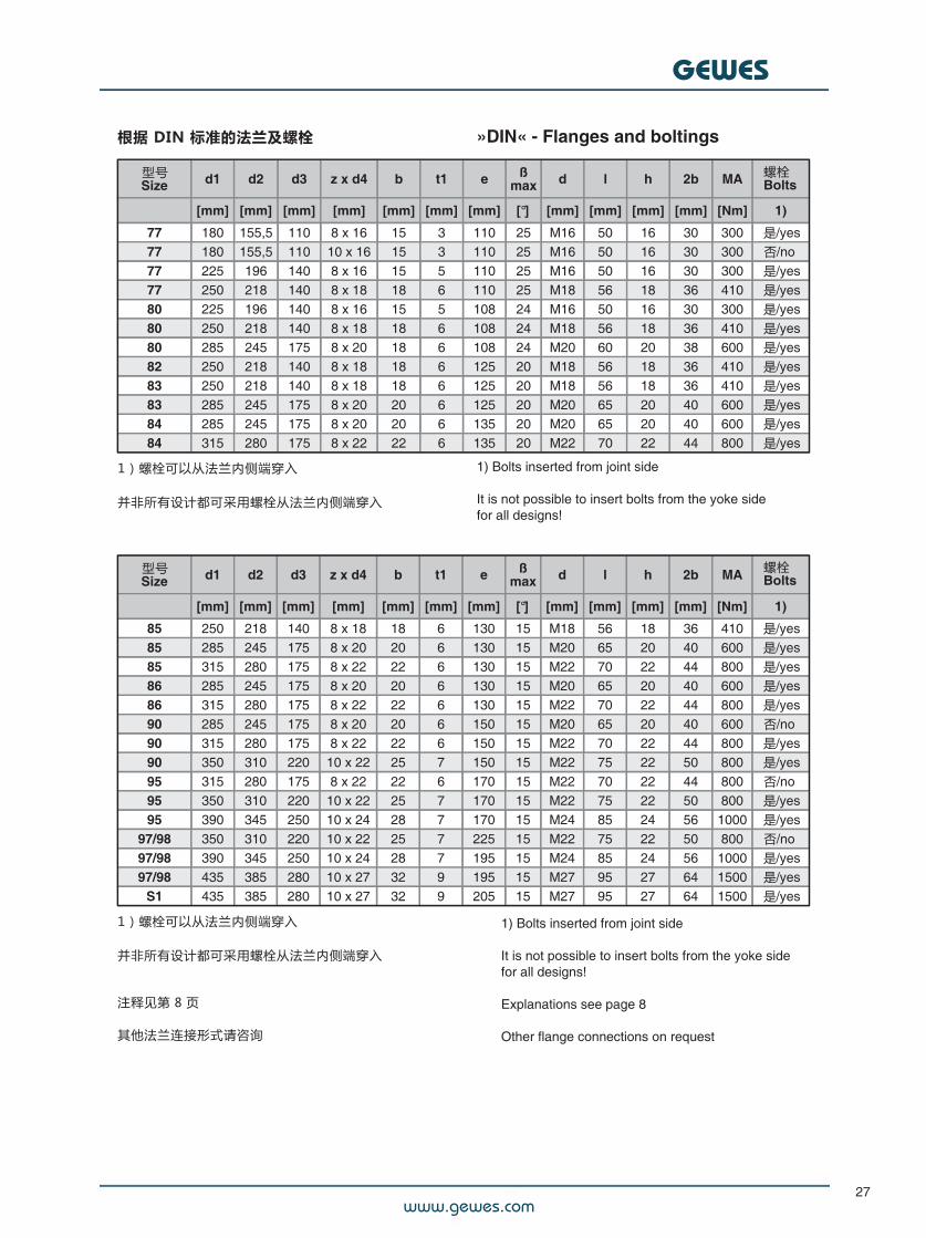
根据 DIN 标准的法兰及螺栓# »DIN« - Flanges and boltings
型号Size d1 d2 d3 z x d4 b t1 e ß
max d l h 2b MA
[mm] [mm] [mm] [mm] [mm] [mm] [mm] [°] [mm] [mm] [mm] [mm] [Nm] 1)
77 180 155,5 110 8 x 16 15 3 110 25 M16 50 16 30 300 是/yes77 180 155,5 110 10 x 16 15 3 110 25 M16 50 16 30 300 否/no77 225 196 140 8 x 16 15 5 110 25 M16 50 16 30 300 是/yes77 250 218 140 8 x 18 18 6 110 25 M18 56 18 36 410 是/yes80 225 196 140 8 x 16 15 5 108 24 M16 50 16 30 300 是/yes80 250 218 140 8 x 18 18 6 108 24 M18 56 18 36 410 是/yes80 285 245 175 8 x 20 18 6 108 24 M20 60 20 38 600 是/yes82 250 218 140 8 x 18 18 6 125 20 M18 56 18 36 410 是/yes83 250 218 140 8 x 18 18 6 125 20 M18 56 18 36 410 是/yes83 285 245 175 8 x 20 20 6 125 20 M20 65 20 40 600 是/yes84 285 245 175 8 x 20 20 6 135 20 M20 65 20 40 600 是/yes84 315 280 175 8 x 22 22 6 135 20 M22 70 22 44 800 是/yes
1)螺栓可以从法兰内侧端穿入
并非所有设计都可采用螺栓从法兰内侧端穿入
1) Bolts inserted from joint side
It is not possible to insert bolts from the yoke sidefor all designs!
型号Size d1 d2 d3 z x d4 b t1 e ß
max d l h 2b MA
[mm] [mm] [mm] [mm] [mm] [mm] [mm] [°] [mm] [mm] [mm] [mm] [Nm] 1)
85 250 218 140 8 x 18 18 6 130 15 M18 56 18 36 410 是/yes85 285 245 175 8 x 20 20 6 130 15 M20 65 20 40 600 是/yes85 315 280 175 8 x 22 22 6 130 15 M22 70 22 44 800 是/yes86 285 245 175 8 x 20 20 6 130 15 M20 65 20 40 600 是/yes86 315 280 175 8 x 22 22 6 130 15 M22 70 22 44 800 是/yes90 285 245 175 8 x 20 20 6 150 15 M20 65 20 40 600 否/no90 315 280 175 8 x 22 22 6 150 15 M22 70 22 44 800 是/yes90 350 310 220 10 x 22 25 7 150 15 M22 75 22 50 800 是/yes95 315 280 175 8 x 22 22 6 170 15 M22 70 22 44 800 否/no95 350 310 220 10 x 22 25 7 170 15 M22 75 22 50 800 是/yes95 390 345 250 10 x 24 28 7 170 15 M24 85 24 56 1000 是/yes
97/98 350 310 220 10 x 22 25 7 225 15 M22 75 22 50 800 否/no97/98 390 345 250 10 x 24 28 7 195 15 M24 85 24 56 1000 是/yes97/98 435 385 280 10 x 27 32 9 195 15 M27 95 27 64 1500 是/yes
S1 435 385 280 10 x 27 32 9 205 15 M27 95 27 64 1500 是/yes
1)螺栓可以从法兰内侧端穿入
并非所有设计都可采用螺栓从法兰内侧端穿入
注释见第 8 页
其他法兰连接形式请咨询
1) Bolts inserted from joint side
It is not possible to insert bolts from the yoke sidefor all designs!
Explanations see page 8
Other flange connections on request
螺栓Bolts
螺栓Bolts
www.gewes.com
GEWES
28
根据 DIN 标准的法兰及螺栓
参见 ISO 7646 及 DIN 15451
»DIN« - Flanges andboltings
See ISO 7646 resp. DIN 15451
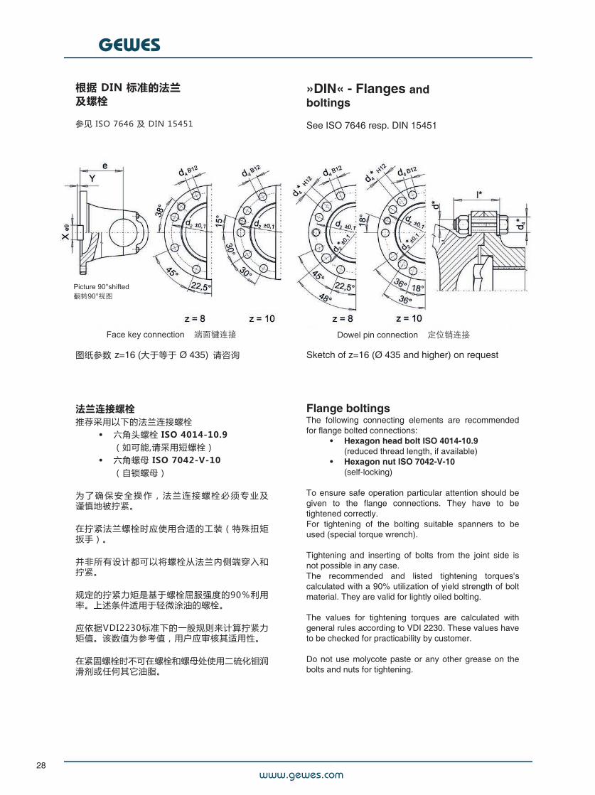
图纸参数 z=16 (大于等于 Ø 435) 请咨询 Sketch of z=16 (Ø 435 and higher) on request
Flange boltingsThe following connecting elements are recommendedfor flange bolted connections:
• Hexagon head bolt ISO 4014-10.9(reduced thread length, if available)
• Hexagon nut ISO 7042-V-10(self-locking)
#To ensure safe operation particular attention should begiven to the flange connections. They have to betightened correctly.For tightening of the bolting suitable spanners to beused (special torque wrench).
Tightening and inserting of bolts from the joint side isnot possible in any case.The recommended and listed tightening torques'scalculated with a 90% utilization of yield strength of boltmaterial. They are valid for lightly oiled bolting.
The values for tightening torques are calculated withgeneral rules according to VDI 2230. These values haveto be checked for practicability by customer.
Do not use molycote paste or any other grease on thebolts and nuts for tightening.
法兰连接螺栓推荐采用以下的法兰连接螺栓
• 六角头螺栓 ISO 4014-10.9(如可能,请采用短螺栓)
• 六角螺母 ISO 7042-V-10(自锁螺母)
为 了 确 保 安 全 操 作 , 法 兰 连 接 螺 栓 必 须 专 业 及谨慎地被拧紧。
在拧紧法兰螺栓时应使用合适的工装(特殊扭矩扳手)。
并非所有设计都可以将螺栓从法兰内侧端穿入和拧紧。
规定的拧紧力矩是基于螺栓屈服强度的90%利用率。上述条件适用于轻微涂油的螺栓。
应依据VDI2230标准下的一般规则来计算拧紧力矩值。该数值为参考值,用户应审核其适用性。
在紧固螺栓时不可在螺栓和螺母处使用二硫化钼润滑剂或任何其它油脂。
www.gewes.com
GEWES
29
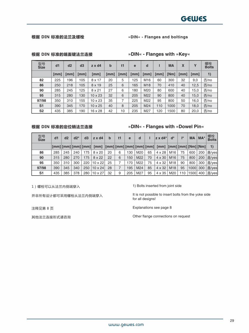
根据 DIN 标准的法兰及螺栓 »DIN« - Flanges and boltings
根据 DIN 标准的端面键法兰连接 »DIN« - Flanges with »Key«
型号Size d1 d2 d3 z x d4 b t1 e d l MA X Y
[mm] [mm] [mm] [mm] [mm] [mm] [mm] [mm] [mm] [Nm] [mm] [mm] 1)
82 225 196 105 8 x 17 20 5 125 M16 60 300 32 9,0 否/no86 250 218 105 8 x 19 25 6 165 M18 70 410 40 12,5 否/no90 285 245 125 8 x 21 27 6 180 M20 80 600 40 15,0 否/no95 315 280 130 10 x 23 32 6 205 M22 90 800 40 15,0 否/no
97/98 350 310 155 10 x 23 35 7 225 M22 95 800 50 16,0 否/noS1 390 345 170 10 x 25 40 8 205 M24 110 1000 70 18,0 否/noS2 435 385 190 16 x 28 42 10 235 M27 120 1500 80 20,0 否/no
根据 DIN 标准的定位销法兰连接 »DIN« - Flanges with »Dowel Pin«
型号Size d1 d2 d2* d3 z x d4 b t1 e d l z x d4* d* l* MA MA*
[mm] [mm] [mm] [mm] [mm] [mm] [mm] [mm] [mm] [mm] [mm] [mm] [mm] [Nm] [Nm] 1)
86 285 245 240 175 8 x 20 20 6 130 M20 65 4 x 28 M16 75 600 200 是/yes90 315 280 270 175 8 x 22 22 6 150 M22 70 4 x 30 M16 75 800 200 是/yes95 350 310 300 220 10 x 22 25 7 170 M22 75 4 x 32 M18 90 800 300 是/yes
97/98 390 345 340 250 10 x 24 28 7 195 M24 85 4 x 32 M18 95 1000 300 是/yesS1 435 385 378 280 10 x 27 32 9 205 M27 95 4 x 35 M20 110 1500 400 是/yes
1)螺栓可以从法兰内侧端穿入
并非所有设计都可采用螺栓从法兰内侧端穿入
注释见第 8 页
其他法兰连接形式请咨询
螺栓Bolts
螺栓Bolts
1) Bolts inserted from joint side
It is not possible to insert bolts from the yoke sidefor all designs!
Explanations see page 8
Other flange connections on request
www.gewes.com
GEWES
30
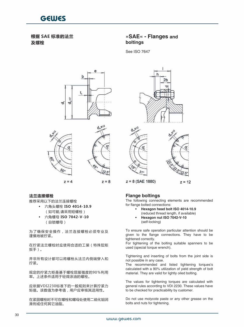
根据 SAE 标准的法兰及螺栓
»SAE« - Flanges andboltings
See ISO 7647
Flange boltingsThe following connecting elements are recommendedfor flange bolted connections:
• Hexagon head bolt ISO 4014-10.9(reduced thread length, if available)
• Hexagon nut ISO 7042-V-10(self-locking)
#To ensure safe operation particular attention should begiven to the flange connections. They have to betightened correctly.For tightening of the bolting suitable spanners to beused (special torque wrench).
Tightening and inserting of bolts from the joint side isnot possible in any case.The recommended and listed tightening torques'scalculated with a 90% utilization of yield strength of boltmaterial. They are valid for lightly oiled bolting.
The values for tightening torques are calculated withgeneral rules according to VDI 2230. These values haveto be checked for practicability by customer.
Do not use molycote paste or any other grease on thebolts and nuts for tightening.
法兰连接螺栓推荐采用以下的法兰连接螺栓
• 六角头螺栓 ISO 4014-10.9(如可能,请采用短螺栓)
• 六角螺母 ISO 7042-V-10(自锁螺母)
为 了 确 保 安 全 操 作 , 法 兰 连 接 螺 栓 必 须 专 业 及谨慎地被拧紧。
在拧紧法兰螺栓时应使用合适的工装(特殊扭矩扳手)。
并非所有设计都可以将螺栓从法兰内侧端穿入和拧紧。
规定的拧紧力矩是基于螺栓屈服强度的90%利用率。上述条件适用于轻微涂油的螺栓。
应依据VDI2230标准下的一般规则来计算拧紧力矩值。该数值为参考值,用户应审核其适用性。
在紧固螺栓时不可在螺栓和螺母处使用二硫化钼润滑剂或任何其它油脂。
www.gewes.com
GEWES
31
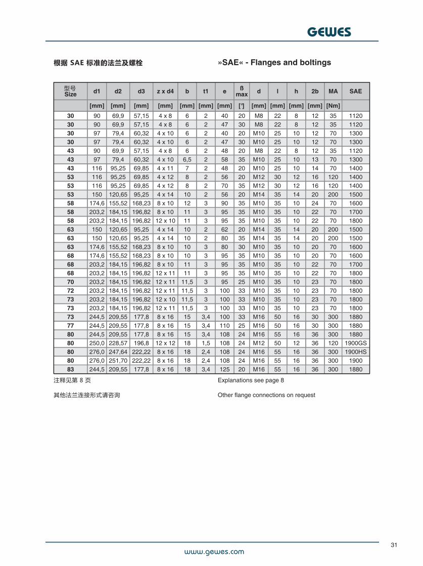
根据 SAE 标准的法兰及螺栓# »SAE« - Flanges and boltings
型号Size d1 d2 d3 z x d4 b t1 e ß
max d l h 2b MA SAE
[mm] [mm] [mm] [mm] [mm] [mm] [mm] [°] [mm] [mm] [mm] [mm] [Nm]
30 90 69,9 57,15 4 x 8 6 2 40 20 M8 22 8 12 35 112030 90 69,9 57,15 4 x 8 6 2 47 30 M8 22 8 12 35 112030 97 79,4 60,32 4 x 10 6 2 40 20 M10 25 10 12 70 130030 97 79,4 60,32 4 x 10 6 2 47 30 M10 25 10 12 70 130043 90 69,9 57,15 4 x 8 6 2 48 20 M8 22 8 12 35 112043 97 79,4 60,32 4 x 10 6,5 2 58 35 M10 25 10 13 70 130043 116 95,25 69,85 4 x 11 7 2 48 20 M10 25 10 14 70 140053 116 95,25 69,85 4 x 12 8 2 56 20 M12 30 12 16 120 140053 116 95,25 69,85 4 x 12 8 2 70 35 M12 30 12 16 120 140053 150 120,65 95,25 4 x 14 10 2 56 20 M14 35 14 20 200 150058 174,6 155,52 168,23 8 x 10 12 3 90 35 M10 35 10 24 70 160058 203,2 184,15 196,82 8 x 10 11 3 95 35 M10 35 10 22 70 170058 203,2 184,15 196,82 12 x 10 11 3 95 35 M10 35 10 22 70 180063 150 120,65 95,25 4 x 14 10 2 62 20 M14 35 14 20 200 150063 150 120,65 95,25 4 x 14 10 2 80 35 M14 35 14 20 200 150063 174,6 155,52 168,23 8 x 10 10 3 80 30 M10 35 10 20 70 160068 174,6 155,52 168,23 8 x 10 10 3 95 35 M10 35 10 20 70 160068 203,2 184,15 196,82 8 x 10 11 3 95 35 M10 35 10 22 70 170068 203,2 184,15 196,82 12 x 11 11 3 95 35 M10 35 10 22 70 180070 203,2 184,15 196,82 12 x 11 11,5 3 95 25 M10 35 10 23 70 180072 203,2 184,15 196,82 12 x 11 11,5 3 100 33 M10 35 10 23 70 180073 203,2 184,15 196,82 12 x 10 11,5 3 100 33 M10 35 10 23 70 180073 203,2 184,15 196,82 12 x 11 11,5 3 100 33 M10 35 10 23 70 180073 244,5 209,55 177,8 8 x 16 15 3,4 100 33 M16 50 16 30 300 188077 244,5 209,55 177,8 8 x 16 15 3,4 110 25 M16 50 16 30 300 188080 244,5 209,55 177,8 8 x 16 15 3,4 108 24 M16 55 16 36 300 188080 250,0 228,57 196,8 12 x 12 18 1,5 108 24 M12 50 12 36 120 1900GS80 276,0 247,64 222,22 8 x 16 18 2,4 108 24 M16 55 16 36 300 1900HS80 276,0 251,70 222,22 8 x 16 18 2,4 108 24 M16 55 16 36 300 190083 244,5 209,55 177,8 8 x 16 18 3,4 125 20 M16 55 16 36 300 1880
注释见第 8 页
其他法兰连接形式请咨询
Explanations see page 8
Other flange connections on request
www.gewes.com
GEWES
32
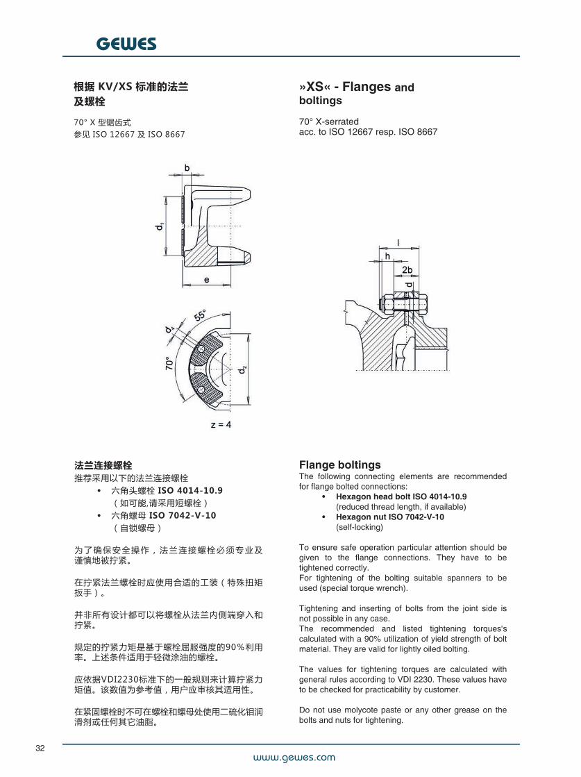
根据 KV/XS 标准的法兰及螺栓
70° X 型锯齿式参见 ISO 12667 及 ISO 8667
»XS« - Flanges andboltings
70° X-serratedacc. to ISO 12667 resp. ISO 8667
Flange boltingsThe following connecting elements are recommendedfor flange bolted connections:
• Hexagon head bolt ISO 4014-10.9(reduced thread length, if available)
• Hexagon nut ISO 7042-V-10(self-locking)
#To ensure safe operation particular attention should begiven to the flange connections. They have to betightened correctly.For tightening of the bolting suitable spanners to beused (special torque wrench).
Tightening and inserting of bolts from the joint side isnot possible in any case.The recommended and listed tightening torques'scalculated with a 90% utilization of yield strength of boltmaterial. They are valid for lightly oiled bolting.
The values for tightening torques are calculated withgeneral rules according to VDI 2230. These values haveto be checked for practicability by customer.
Do not use molycote paste or any other grease on thebolts and nuts for tightening.
法兰连接螺栓推荐采用以下的法兰连接螺栓
• 六角头螺栓 ISO 4014-10.9(如可能,请采用短螺栓)
• 六角螺母 ISO 7042-V-10(自锁螺母)
为 了 确 保 安 全 操 作 , 法 兰 连 接 螺 栓 必 须 专 业 及谨慎地被拧紧。
在拧紧法兰螺栓时应使用合适的工装(特殊扭矩扳手)。
并非所有设计都可以将螺栓从法兰内侧端穿入和拧紧。
规定的拧紧力矩是基于螺栓屈服强度的90%利用率。上述条件适用于轻微涂油的螺栓。
应依据VDI2230标准下的一般规则来计算拧紧力矩值。该数值为参考值,用户应审核其适用性。
在紧固螺栓时不可在螺栓和螺母处使用二硫化钼润滑剂或任何其它油脂。
www.gewes.com
GEWES
33
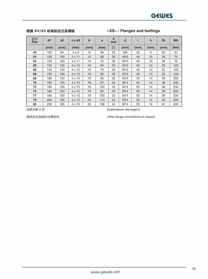
根据 KV/XS 标准的法兰及螺栓 »XS« - Flanges and boltings
型号Size d1 d2 z x d4 b e ß
max d l h 2b MA
[mm] [mm] [mm] [mm] [mm] [°] [mm] [mm] [mm] [mm] [Nm]
43 100 84 4 x 8 10 58 35 M8 30 8 20 3553 120 100 4 x 11 14 68 35 M10 40 10 28 7063 120 100 4 x 11 14 75 35 M10 40 10 28 7058 152 130 4 x 13 16 95 35 M12 45 12 32 12068 152 130 4 x 13 16 75 20 M12 45 12 32 12068 152 130 4 x 13 16 95 35 M12 45 12 32 12068 180 150 4 x 15 18 95 35 M14 55 14 36 20070 180 150 4 x 15 18 87 25 M14 55 14 36 20072 180 150 4 x 15 18 100 35 M14 55 14 36 20073 180 150 4 x 15 18 95 30 M14 55 14 36 20077 180 150 4 x 15 18 100 22 M14 55 14 36 20079 200 165 4 x 15 20 113 22 M14 55 14 40 20080 200 165 4 x 15 20 108 24 M14 55 14 40 200
注释见第 8 页
其他法兰连接形式请咨询
Explanations see page 8
Other flange connections on request
www.gewes.com
GEWES
34
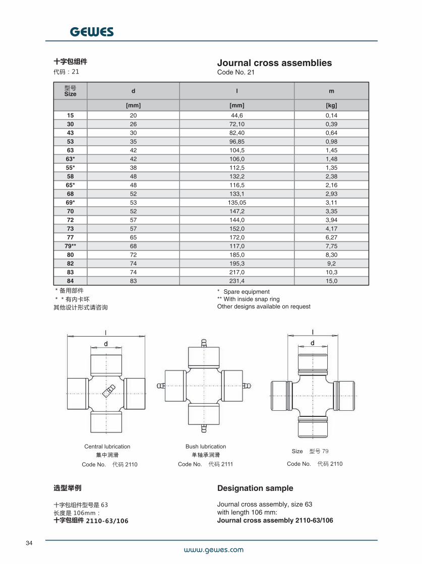
十字包组件代码:21
Journal cross assembliesCode No. 21
型号Size d l m
[mm] [mm] [kg]
15 20 44,6 0,1430 26 72,10 0,3943 30 82,40 0,6453 35 96,85 0,9863 42 104,5 1,4563* 42 106,0 1,4855* 38 112,5 1,3558 48 132,2 2,3865* 48 116,5 2,1668 52 133,1 2,9369* 53 135,05 3,1170 52 147,2 3,3572 57 144,0 3,9473 57 152,0 4,1777 65 172,0 6,27
79** 68 117,0 7,7580 72 185,0 8,3082 74 195,3 9,283 74 217,0 10,384 83 231,4 15,0
*备用部件**有内卡环其他设计形式请咨询
** Spare equipment** With inside snap ringOther designs available on request
选型举例
十字包组件型号是 63长度是 106mm:十字包组件 2110-63/106
Designation sample
Journal cross assembly, size 63with length 106 mm:Journal cross assembly 2110-63/106
www.gewes.com
GEWES
35
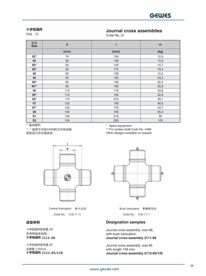
十字包组件代码:21
Journal cross assembliesCode No. 21
型号Size d l m
[mm] [mm] [kg]
82* 74 154 12,985 83 139 15,085* 83 129 14,785* 83 175 19,486 83 139 15,090 95 160 23,390* 95 139 22,390** 95 190 26,895 110 176 33,895* 110 160 32,895* 110 210 39,197 120 196 46,697* 120 176 43,798 130 196 55,3S1 130 216 58S2 154 250 105
*备用部件**适用于代码4496的万向传动轴其他设计形式请咨询
** Spare equipment** For cardan shaft Code No. 4496Other designs available on request
选型举例
十字包组件型号是 68采用单轴承润滑:十字包组件 2111-68
十字包组件型号是 85长度是 139mm十字包组件 2112-85/139
Designation samples
Journal cross assembly, size 68,with bush lubrication:Journal cross assembly 2111-68
Journal cross assembly, size 85with length 139 mm:Journal cross assembly 2112-85/139
www.gewes.com
GEWES
36
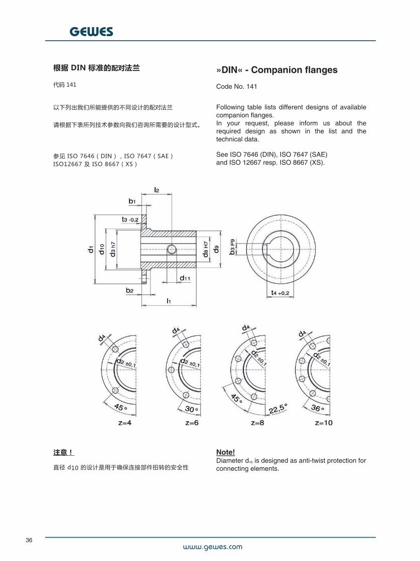
根据 DIN 标准的配对法兰
代码 141
»DIN« - Companion flanges
Code No. 141
以下列出我们所能提供的不同设计的配对法兰
请根据下表所列技术参数向我们咨询所需要的设计型式。
参见 ISO 7646(DIN),ISO 7647(SAE)ISO12667 及 ISO 8667(XS)
Following table lists different designs of availablecompanion flanges.In your request, please inform us about therequired design as shown in the list and thetechnical data.
See ISO 7646 (DIN), ISO 7647 (SAE)and ISO 12667 resp. ISO 8667 (XS).
注意!
直径 d10 的设计是用于确保连接部件扭转的安全性
Note!Diameter d10 is designed as anti-twist protection forconnecting elements.
www.gewes.com
GEWES
37
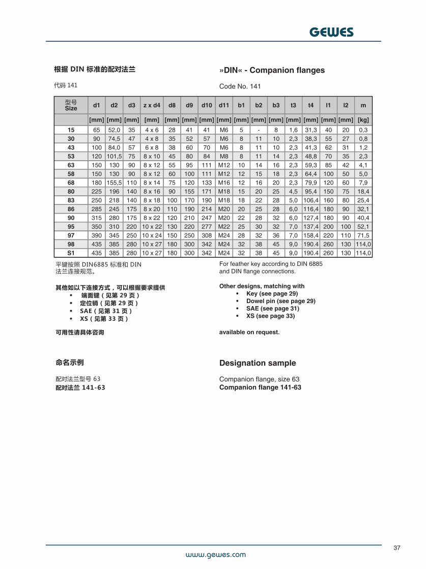
根据 DIN 标准的配对法兰
代码 141
»DIN« - Companion flanges
Code No. 141
型号Size d1 d2 d3 z x d4 d8 d9 d10 d11 b1 b2 b3 t3 t4 l1 l2 m
[mm] [mm] [mm] [mm] [mm] [mm] [mm] [mm] [mm] [mm] [mm] [mm] [mm] [mm] [mm] [kg]
15 65 52,0 35 4 x 6 28 41 41 M6 5 - 8 1,6 31,3 40 20 0,330 90 74,5 47 4 x 8 35 52 57 M6 8 11 10 2,3 38,3 55 27 0,843 100 84,0 57 6 x 8 38 60 70 M6 8 11 10 2,3 41,3 62 31 1,253 120 101,5 75 8 x 10 45 80 84 M8 8 11 14 2,3 48,8 70 35 2,363 150 130 90 8 x 12 55 95 111 M12 10 14 16 2,3 59,3 85 42 4,158 150 130 90 8 x 12 60 100 111 M12 12 15 18 2,3 64,4 100 50 5,068 180 155,5 110 8 x 14 75 120 133 M16 12 16 20 2,3 79,9 120 60 7,980 225 196 140 8 x 16 90 155 171 M18 15 20 25 4,5 95,4 150 75 18,483 250 218 140 8 x 18 100 170 190 M18 18 22 28 5,0 106,4 160 80 25,486 285 245 175 8 x 20 110 190 214 M20 20 25 28 6,0 116,4 180 90 32,190 315 280 175 8 x 22 120 210 247 M20 22 28 32 6,0 127,4 180 90 40,495 350 310 220 10 x 22 130 220 277 M22 25 30 32 7,0 137,4 200 100 52,197 390 345 250 10 x 24 150 250 308 M24 28 32 36 7,0 158,4 220 110 71,598 435 385 280 10 x 27 180 300 342 M24 32 38 45 9,0 190.4 260 130 114,0S1 435 385 280 10 x 27 180 300 342 M24 32 38 45 9,0 190.4 260 130 114,0
For feather key according to DIN 6885and DIN flange connections.
Other designs, matching with• Key (see page 29)• Dowel pin (see page 29)• SAE (see page 31)• XS (see page 33)
available on request.
Designation sample
Companion flange, size 63Companion flange 141-63
平键按照 DIN6885 标准和 DIN法兰连接规范。
其他如以下连接方式,可以根据要求提供• 端面键(见第 29 页)• 定位销(见第 29 页)• SAE(见第 31 页)• XS(见第 33 页)
可用性请具体咨询
命名示例
配对法兰型号 63配对法兰 141-63
www.gewes.com
GEWES
38
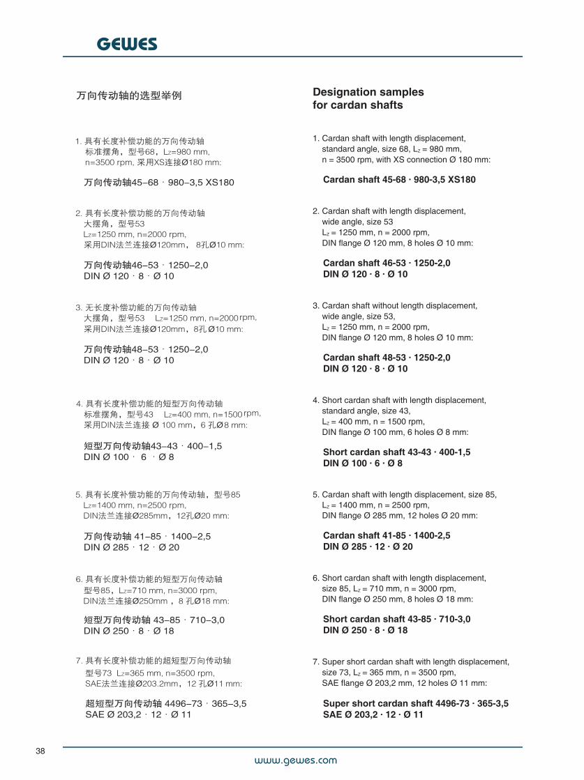
Designation samplesfor cardan shafts##1. Cardan shaft with length displacement,##standard angle, size 68, LZ = 980 mm,##n = 3500 rpm, with XS connection Ø 180 mm:###Cardan shaft 45-68 · 980-3,5 XS180##2. Cardan shaft with length displacement,##wide angle, size 53##LZ = 1250 mm, n = 2000 rpm,##DIN flange Ø 120 mm, 8 holes Ø 10 mm:###Cardan shaft 46-53 · 1250-2,0##DIN Ø 120 · 8 · Ø 10##3. Cardan shaft without length displacement,##wide angle, size 53,##LZ = 1250 mm, n = 2000 rpm,##DIN flange Ø 120 mm, 8 holes Ø 10 mm:###Cardan shaft 48-53 · 1250-2,0##DIN Ø 120 · 8 · Ø 10##4. Short cardan shaft with length displacement,##standard angle, size 43,##LZ = 400 mm, n = 1500 rpm,##DIN flange Ø 100 mm, 6 holes Ø 8 mm:###Short cardan shaft 43-43 · 400-1,5##DIN Ø 100 · 6 · Ø 8##5. Cardan shaft with length displacement, size 85,##LZ = 1400 mm, n = 2500 rpm,##DIN flange Ø 285 mm, 12 holes Ø 20 mm:###Cardan shaft 41-85 · 1400-2,5##DIN Ø 285 · 12 · Ø 20##6. Short cardan shaft with length displacement,##size 85, LZ = 710 mm, n = 3000 rpm,##DIN flange Ø 250 mm, 8 holes Ø 18 mm:###Short cardan shaft 43-85 · 710-3,0##DIN Ø 250 · 8 · Ø 18##7. Super short cardan shaft with length displacement,##size 73, LZ = 365 mm, n = 3500 rpm,##SAE flange Ø 203,2 mm, 12 holes Ø 11 mm:###Super short cardan shaft 4496-73 · 365-3,5##SAE Ø 203,2 · 12 · Ø 11
www.gewes.com
GEWES
39
万向传动轴在工程应用上的建议
Application engineeringadvice on the useof cardan shafts
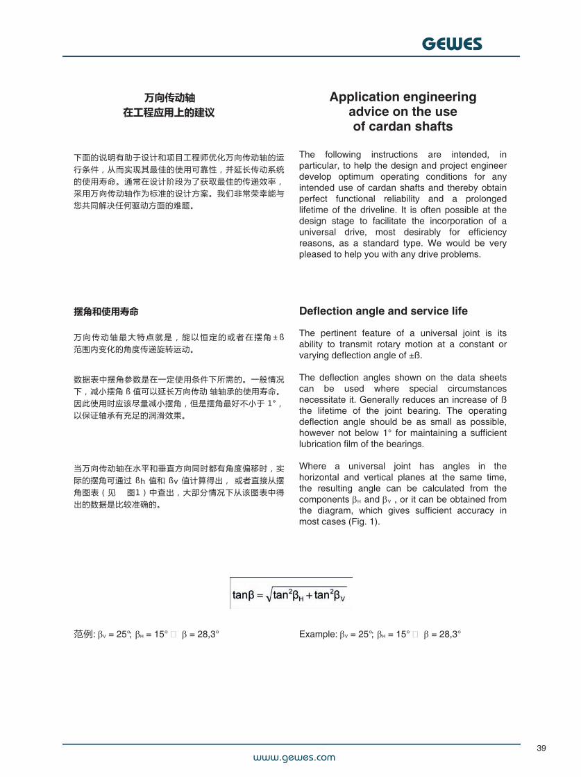
摆角和使用寿命
万 向 传 动 轴 最 大 特 点 就 是 , 能 以 恒 定 的 或 者 在 摆 角 ± ß范围内变化的角度传递旋转运动。
数据表中摆角参数是在一定使用条件下所需的。一般情况下,减小摆角 ß 值可以延长万向传动 轴轴承的使用寿命。因此使用时应该尽量减小摆角,但是摆角最好不小于 1°,以保证轴承有充足的润滑效果。
#
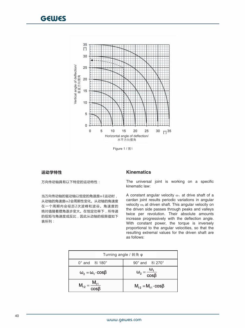
当万向传动轴在水平和垂直方向同时都有角度偏移时,实际的摆角可通过 ßh 值和 ßv 值计算得出, 或者直接从摆角图表(见 图1)中查出,大部分情况下从该图表中得出的数据是比较准确的。#
Deflection angle and service life
The pertinent feature of a universal joint is itsability to transmit rotary motion at a constant orvarying deflection angle of ±ß .
The deflection angles shown on the data sheetscan be used where special circumstancesnecessitate it. Generally reduces an increase of ßthe lifetime of the joint bearing. The operatingdeflection angle should be as small as possible,however not below 1° for maintaining a sufficientlubrication film of the bearings.##Where a universal joint has angles in thehorizontal and vertical planes at the same time,the resulting angle can be calculated from thecomponents H and V , or it can be obtained fromthe diagram, which gives sufficient accuracy inmost cases (Fig. 1).
范例: V = 25°; H = 15° = 28,3° Example: V = 25°; H = 15° = 28,3°
下面的说明有助于设计和项目工程师优化万向传动轴的运行条件,从而实现其最佳的使用可靠性,并延长传动系统的使用寿命。通常在设计阶段为了获取最佳的传递效率,采用万向传动轴作为标准的设计方案。我们非常荣幸能与您共同解决任何驱动方面的难题。
The following instructions are intended, inparticular, to help the design and project engineerdevelop optimum operating conditions for anyintended use of cardan shafts and thereby obtainperfect functional reliability and a prolongedlifetime of the driveline. It is often possible at thedesign stage to facilitate the incorporation of auniversal drive, most desirably for efficiencyreasons, as a standard type. We would be verypleased to help you with any drive problems.
www.gewes.com
GEWES
40
Kinematics
The universal joint is working on a specifickinematic law:
A constant angular velocity 1 at drive shaft of acardan joint results periodic variations in angularvelocity 2 at driven shaft. This angular velocity onthe driven side passes through peaks and valleystwice per revolution. Their absolute amountsincrease progressively with the deflection angle.With constant power, the torque is inverselyproportional to the angular velocities, so that theresulting extremal values for the driven shaft areas follows:
运动学特性
万向传动轴具有以下特定的运动特性:
当万向传动轴的驱动轴以恒定的角速度1运动时,从动轴的角速度2会周期性变化。从动轴的角速度在 一 个 周 期 内 会 经 历 2 次 波 峰 和 波 谷 。 角 速 度 的绝对值随着摆角逐步变大。在恒定功率下,所传递的扭矩与角速度成反比,因此从动轴的极限值如下表所列:
www.gewes.com
GEWES
41
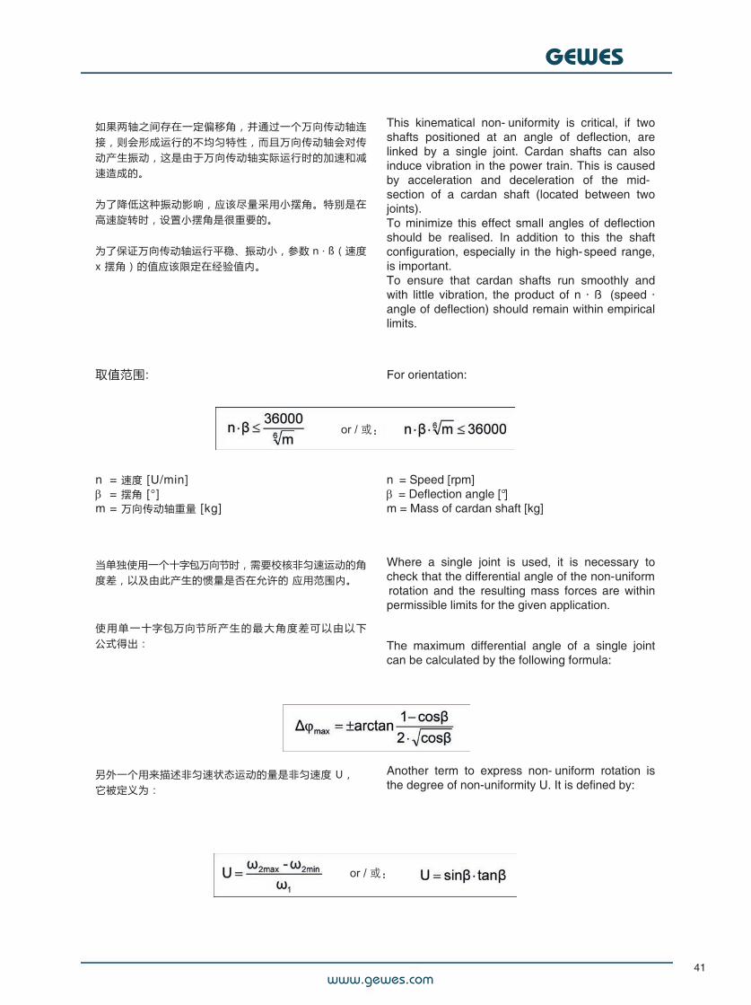
如果两轴之间存在一定偏移角,并通过一个万向传动轴连接,则会形成运行的不均匀特性,而且万向传动轴会对传动产生振动,这是由于万向传动轴实际运行时的加速和减速造成的。
为了降低这种振动影响,应该尽量采用小摆角。特别是在高速旋转时,设置小摆角是很重要的。
为了保证万向传动轴运行平稳、振动小,参数 n ∙ ß(速度x 摆角)的值应该限定在经验值内。
This kinematical non- uniformity is critical, if twoshafts positioned at an angle of deflection, arelinked by a single joint. Cardan shafts can alsoinduce vibration in the power train. This is causedby acceleration and deceleration of the mid-section of a cardan shaft (located between twojoints).To minimize this effect small angles of deflectionshould be realised. In addition to this the shaftconfiguration, especially in the high-speed range,is important.To ensure that cardan shafts run smoothly andwith little vibration, the product of n · ß (speed ·angle of deflection) should remain within empiricallimits.
取值范围: For orientation:
ni = 速度 [U/min]i = 摆角 [°]m = 万向传动轴重量 [kg]
当单独使用一个十字包万向节时,需要校核非匀速运动的角度差,以及由此产生的惯量是否在允许的 应用范围内。
使 用 单 一 十字包万向节所 产 生 的 最 大 角 度 差 可 以 由 以 下公式得出:
ni = Speed [rpm]i = Deflection angle [°]m = Mass of cardan shaft [kg]
Where a single joint is used, it is necessary tocheck that the differential angle of the non-uniformrotation and the resulting mass forces are withinpermissible limits for the given application.
The maximum differential angle of a single jointcan be calculated by the following formula:
另外一个用来描述非匀速状态运动的量是非匀速度 U,它被定义为:
Another term to express non- uniform rotation isthe degree of non-uniformity U. It is defined by:
www.gewes.com
GEWES
42
万向传动轴的布置
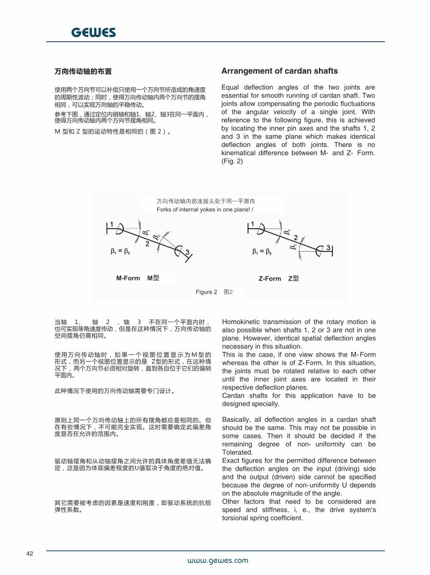
使用两个万向节可以补偿只使用一个万向节所造成的角速度的周期性波动;同时,使得万向传动轴内两个万向节的摆角相同,可以实现万向轴的平稳传动。
参考下图,通过定位内销轴和轴1、轴2、轴3在同一平面内,使得万向传动轴内两个万向节摆角相同。
M 型和 Z 型的运动特性是相同的(图 2)。
Arrangement of cardan shafts
Equal deflection angles of the two joints areessential for smooth running of cardan shaft. Twojoints allow compensating the periodic fluctuationsof the angular velocity of a single joint. Withreference to the following figure, this is achievedby locating the inner pin axes and the shafts 1, 2and 3 in the same plane which makes identicaldeflection angles of both joints. There is nokinematical difference between M- and Z- Form.(Fig. 2)
当轴 1、 轴 2 、轴 3 不在同一个平面内时,也可实现等角速度传动,但是在这种情况下,万向传动轴的空间摆角仍需相同。
使 用 万 向 传 动 轴 时 , 如 果 一 个 视 图 位 置 显 示 为 M 型 的形式,而另一个视图位置显示的是 Z型的形式,在这种情况下,两个万向节必须相对旋转,直到各自位于它们的偏转平面内。
此种情况下使用的万向传动轴需要专门设计。
原则上同一个万向传动轴上的所有摆角都应是相同的。但在有些情况下,不可能完全实现。这时需要确定此偏差角度是否在允许的范围内。
驱动轴摆角和从动轴摆角之间允许的具体角度差值无法确定,这是因为体现偏差程度的U值取决于角度的绝对值。
其它需要被考虑的因素是速度和刚度,即驱动系统的抗扭弹性系数。
Homokinetic transmission of the rotary motion isalso possible when shafts 1, 2 or 3 are not in oneplane. However, identical spatial deflection anglesnecessary in this situation.This is the case, if one view shows the M- Formwhereas the other is of Z- Form. In this situation,the joints must be rotated relative to each otheruntil the inner joint axes are located in theirrespective deflection planes.Cardan shafts for this application have to bedesigned specially.
Basically, all deflection angles in a cardan shaftshould be the same. This may not be possible insome cases. Then it should be decided if theremaining degree of non- uniformity can beTolerated.Exact figures for the permitted difference betweenthe deflection angles on the input (driving) sideand the output (driven) side cannot be specifiedbecause the degree of non-uniformity U dependson the absolute magnitude of the angle.Other factors that need to be considered arespeed and stiffness, i. e., the drive system'storsional spring coefficient.
www.gewes.com
GEWES
43
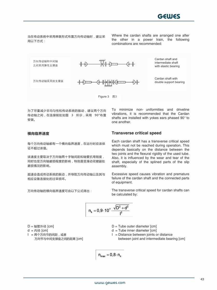
当在传动系统中采用串联形式布置万向传动轴时,建议采用以下方式:
Where the cardan shafts are arranged one afterthe other in a power train, the followingcombinations are recommended:
为了尽量减少非均匀性和传动系统的振动,建议两个万向传动轴之间,在连接轭处如图 3 所示,采用 90°布置安装。
To minimize non- uniformities and drivelinevibrations, it is recommended that the Cardanshafts are installed with yokes ears phased 90o toone another.
横向临界速度
每个万向传动轴都有一个横向临界速度,在运行时应该保证不超过该值。
该速度主要取决于万向轴两十字轴间距和轴管抗弯刚度,同时也受万向轴磨损程度的影响,特别是受滑动花键副处磨损情况的影响。
超速会造成传动系统的振动,并导致万向传动轴以及其与相应设备连接处的过早损坏。
万向传动轴的横向临界速度可由以下公式得出:
Transverse critical speed
Each cardan shaft has a transverse critical speedwhich must not be reached during operation. Thisdepends basically on the distance between thetwo joints and the flexural rigidity of the used tube.Also, it is influenced by the wear and tear of theshaft, especially of the splined parts of the slipassembly.
Excessive speed causes vibration and prematurefailure of the cardan shaft and the connected partsof equipment.
The transverse critical speed for cardan shafts canbe calculated by:
D = 轴管外径 [cm]di = 内径 [cm]Iv = 两个万向节的间距,或者 万向节与中间支撑座之间的距离 [cm]
D = Tube outer diameter [cm]di = Tube inner diameter [cm]Iv = Distance between joints or distance#i##between joint and intermediate bearing [cm]
www.gewes.com
GEWES
44
正常的工作速度不能超过计算得出的临界速度的80%。
可以通过增加轴管外径的方式来提高临界速度。否则就需要采用两个万向传动轴,并且在中间采用支撑座的传动方案。这种情况对摆角有一些特殊的要求。
我们建议您联系我们的设计工程师来进行咨询。
The operating speed should not exceed 80 % ofthe critical speed calculated.Critical speed can be increased by using tubeswith bigger outside diameters. Otherwise theapplication would require using an arrangement oftwo cardan shafts with an intermediate bearinginstead of one cardan shaft. This involves certainrequirements with respect to the deflection angle.For advice contact our design engineers.
长度和速度的限制
带 轴 管 的 万 向 传 动 轴 的 长 度 取 决 于 临 界 转 速 和 生 产 设 备的能力。
可以实现动平衡的万向传动轴的最大长度L = 6000 mm如需更长的万向传动轴,请咨询。
Limitations of length and speed
The length of tubular cardan shafts is limited bythe critical speed of the shaft and by the limits ofproduction faclities.The largest length, which can be balanced isL = 6000 mm.Larger length options on request.
万向传动轴的动平衡
除了低速条件下的应用外,万向传动轴都需要进行动平衡测试。动平衡能保证万向传动轴的平稳运行,并降低由于离心力而对轴承的损坏。
根据实际需求,可以按照DIN IS0 1940 标准(图4)采用不同的动平衡等级。
Balancing of cardan shafts
Unless some low speed applications cardan shaftsare balanced dynamically. Dynamic balancingguarantees smooth running of the cardan shaftand minimizes loads on the bearings caused bycentrifugal forces.Depending on the specific requirements, balancingis done in various quality categories according toDIN IS0 1940. (Fig. 4)
www.gewes.com
GEWES
45
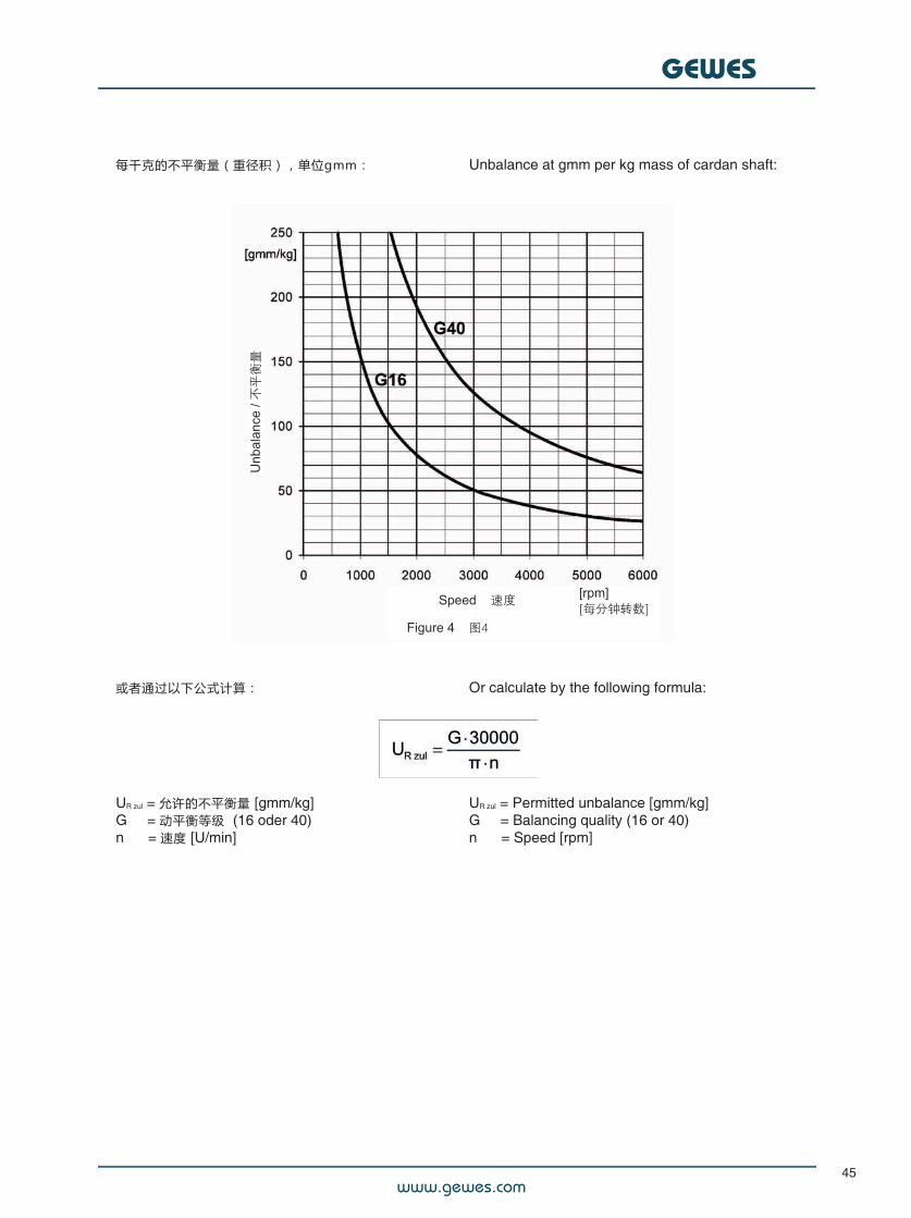
每千克的不平衡量(重径积),单位gmm: Unbalance at gmm per kg mass of cardan shaft:
或者通过以下公式计算: Or calculate by the following formula:
UR zul = 允许的不平衡量 [gmm/kg]G## = 动平衡等级 (16 oder 40)n ## = 速度 [U/min]
UR zul = Permitted unbalance [gmm/kg]G## = Balancing quality (16 or 40)n ## = Speed [rpm]
www.gewes.com
GEWES
46
非工作状态下的弯矩
由于万向传动轴摆角的存在而产生的偏移动能,会在万向传动轴的联接端产生剪切力和弯矩。
假设摆角为90°,就可以很清楚地了解到这样的现象对于实际的扭矩传递是毫无用处的,因为此时驱动轴所有的扭矩全部转化从动轴的弯矩。对于连接着万向传动轴的轴末端,这产生了侧推力和弯矩的重合,而不会产生横向力。
这意味着对联接轴的轴承产生了额外力。特别是在大摆角和大扭矩的情况下,此情况必须在轴的设计时予以考虑。
Non-operating bending moment
The deflection of the power flow through deflectionangle of the joint causes transverse forces andbending moments on the shaft ends which supportthe joint or cardan shaft.This phenomenon becomes particularly clear ifone imagines the practically useless deflectionangle of 90°, in which the entire torque of onedrive fork acts as bending moment in the other.For the shaft ends connected to the cardan shaftthis creates a superposition of lateral thrust andbending which is free of transverse forces. So thismeans additional load on the bearings of theseconnected shafts, especially at high angles andtorques, a consideration which must be taken intoaccount in the design of the drive.
万向传动轴的选型和使用
万向传动轴应用广泛。所以无法根据单一的规则,对万向传动轴进行精确的选型,并预测其使用寿命。
我 们 所 熟 悉 的 滚 子 轴 承 的 失 效 概 论 同 样 适 用 于 万 向 传 动轴。
万向传动轴的选型原则是,它的最大瞬时扭矩值,不小于该工况下需要传递的最大扭矩。其他参数如摆角、速度、长 度 、 工 况 ( 驱 动 类 型 、 环 境 温 度 、 灰 尘 等 ) 也 应 予以考虑。
因 此 , 请 参 考 我 们 的 技 术 参 数 调 查 问 卷 , 可 以 到 网 址www.gewes.de 上下载。我们的技术人员会根据调查问 卷 中 的 信 息 进 行 评 估 , 为 你 们 的 应 用 选 择 最 适 合 的产品。如果你们需要使用寿命的决定因素、稳定性等具体计算,请联系我哦们。
Selection and use of cardan shafts
Cardan shafts being used for various applications.So it is impossible to select their size and predicttheir lifetime with reliable accuracy with just onegeneral rule.The familiar failure probabilities for roller bearingsapply to cardan shafts as well.The size of the cardan shaft should be chosen sothat its maximum momentary torque rating, is notsmaller than the maximum torque to betransmitted in your application. Additionallyparameters like deflection angle, speed, length,operating conditions (kind of drive, temperature,dust etc.) should be considered. Therefore pleaserefer to our technical questionnaire. This isavailable for download on www.gewes.de . Ourexperts will evaluate your information given in thisquestionnaire, to find the best choice for yourapplication. If you need more detailed calculationslike determining lifetime, stability etc. pleasecontact us.
如果在万向轴选型时,客户完全根据样本内的数据,而没有咨询我们的专家;正确解释的责任完全在于客户。在这种情况下,Gelenkwellenwerk StadtilmGmbH不承担由选型造成的损害赔偿责任。
In the case of the selection of the cardan shaftsexclusively according to the data of the catalogue,without consulting our experts, the responsibility of thecorrect interpretation lies solely with the customer. Insuch a case, Gelenkwellenwerk Stadtilm GmbH shallnot be liable for damages resulting from faulty selection.
Exclusion of Liability免责声明
www.gewes.com
GEWES
47
安装说明
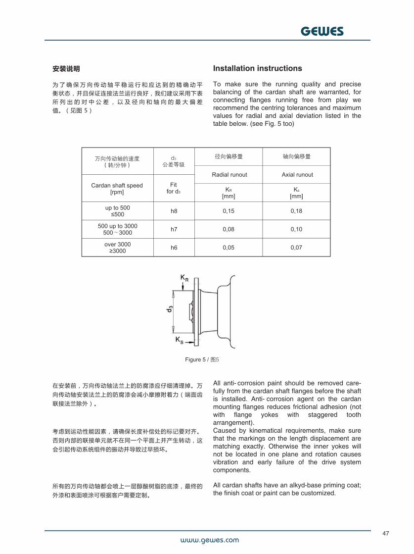
为 了 确 保 万 向 传 动 轴 平 稳 运 行 和 应 达 到 的 精 确 动 平衡状态,并且保证连接法兰运行良好,我们建议采用下表所 列 出 的 对 中 公 差 , 以 及 径 向 和 轴 向 的 最 大 偏 差值。(见图 5)
Installation instructions
To make sure the running quality and precisebalancing of the cardan shaft are warranted, forconnecting flanges running free from play werecommend the centring tolerances and maximumvalues for radial and axial deviation listed in thetable below. (see Fig. 5 too)
在安装前,万向传动轴法兰上的防腐漆应仔细清理掉。万向传动轴安装法兰上的防腐漆会减小摩擦附着力(端面齿联接法兰除外)。
考虑到运动性能因素,请确保长度补偿处的标记要对齐。否则内部的联接单元就不在同一个平面上并产生转动,这会引起传动系统组件的振动并导致过早损坏。
所有的万向传动轴都会喷上一层醇酸树脂的底漆,最终的外漆和表面喷涂可根据客户需要定制。
All anti- corrosion paint should be removed care-fully from the cardan shaft flanges before the shaftis installed. Anti- corrosion agent on the cardanmounting flanges reduces frictional adhesion (notwith flange yokes with staggered tootharrangement).Caused by kinematical requirements, make surethat the markings on the length displacement arematching exactly. Otherwise the inner yokes willnot be located in one plane and rotation causesvibration and early failure of the drive systemcomponents.
All cardan shafts have an alkyd-base priming coat;the finish coat or paint can be customized.
www.gewes.com
GEWES
48
万向传动轴的维护
需要定期对万向传动轴的运动部件加润滑脂,以去除失效的润滑脂和异物,并补充所需润滑脂。
在对万向传动轴进行高压或蒸汽喷射清洗后,必须重新加润滑脂。
Cardan shaft maintenance
It is necessary to grease the moving parts of acardan shaft at certain intervals to remove usedlubricant and foreign matter, if any, and reple-nishing the lubricant.Lubrication is required after cleaning with highpressure or a steam jet.
保养程序
对十字轴和滑动组件加润滑脂时,采用符合DIN71412标准的锥形油嘴,或符合DIN3404标准的平头油嘴。如果一个十 字 轴 上 有 两 个 相 对 的 润 滑 点 , 仅 需 对 一 个 润 滑 点 加润滑脂。
在加润滑脂前必须要确保油嘴已经清理干净。
润滑脂通过管路润滑到十字轴的四个轴承。当油脂从密封处渗漏出来时,停止加注。
在加润滑脂时应避免用力拍打或者撞击,这样会损坏油封。
在对采用花键连接的长度补偿型万向传动轴加润滑脂时,要控制润滑脂的加注量,以避免过大液压力损害轴向的运动。
表面覆有Rilsan涂层的花键是终身免润滑的。
Maintenance procedure
Lubricant is supplied to the joints and the slipassembly by taper lubricator nipples acc. to DIN71412 or flat lubricator nipples acc. to DIN 3404.Where two lubricating points placed on one jointopposite to each other, lubricant need only besupplied at one nipple. Make absolutely sure toclean the lubricator nipples before lubrication. Thegrease reaches four joint bearings through theducts in the spider. Supply lubricant until lubricantemerges from the seals. When supplying lubricantavoid harsh strokes or forceful impact that candamage the seals.The splined shaft connection of the lengthdisplacement of cardan shaft requires a controlledsupply of lubricant in order to avoid high hydraulicforces that impair the axial movement. Rilsan-coated spline shaft connections are lifetimelubricated.
润滑剂
我们建议使用符合DIN 51502标准的 KP 1-2 N-30 或 KP2N-20的,带EP添加剂锂基润滑油,这适用于欧洲的气候条件。也可以采用符合 KP 2 N-40或 KP 3 N-40 规格的防冻润滑油,在温度低于-40 °C.时仍可以正常使用。
不同基质的润滑脂不可混用。
万向传动轴的轴承不可使用含二硫化钼或固态润滑添加剂的润滑脂。
Lubricant
We recommend the use of lithiumcomplex greasesof specification KP 1- 2 N- 30 or KP 2 N- 20 DIN51502 with EP additives for European climates orof non- freezing grease of the same base ofspecification KP 2 N- 40 or KP 3 N- 40 for use intemperatures of down to -40 °C.Lubricant should never be replenished with agrease of a different soap base.Do not grease cardan shaft bearings with MoS2 orother solid lubricant additives.
www.gewes.com
GEWES
49
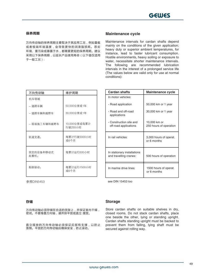
保养周期
万向传动轴的保养周期主要取决于其应用工况,例如重载或 者 极 端 环 境 温 度 , 会 导 致 更 快 的 润 滑 脂 损 耗 。 恶 劣环境、重污染或暴露于水,都需要更短的保养周期。建议采用以下保养周期,以延长产品使用寿命(以下值仅适用于一般工况):
Maintenance cycle
Maintenance intervals for cardan shafts dependmainly on the conditions of the given application;heavy duty or superior ambient temperatures, forinstance, lead to faster lubricant consumption.Hostile environments, heavy soiling or exposure towater, necessitate shorter maintenance intervals.The following are recommended lubricationintervals in the interest of a prolonged service life(The values below are valid only for use at normalconditions):
Cardan shafts Maintenance cycleIn motor vehicles:
- Road application
- Road and off-road#applications
- Construction site and#off-road applications#
50,000 km or 1 year
30,000 km or 1 year
10,000 km or250 hours of operation#
In rail vehicles:##
3,000 hours of operat.or 6 months#
In stationary installationsand travelling cranes:#
500 hours of operation#
In marine drive lines:##
1500 hours of operat.or 6 months
see DIN 15453 too
存储
万向传动轴必须存储在合适的货架上,并保证室内干燥,密闭。不要堆叠万向轴,请并排平放或直立 摆放。
直 立 摆 放 的 万 向 传 动 轴 必 须 保 证 后 部 有 支 撑 , 以 防 止落倒。平放的万向传动轴应确保安全,防止滚动。
Storage
Store cardan shafts on suitable shelves in dry,closed rooms. Do not stack cardan shafts, placeone beside the other, lying or standing upright.Cardan shafts standing upright must be backed toprevent them from falling, lying shaft must besecured against rolling way.
www.gewes.com
GEWES
50
安全注意事项
旋转的万向传动轴具有危险性!
用户必须严格遵守安全标准,并采取适当的防护措施,如安装防护隔断或防护盖。
请遵守有关机械产品的 EC 规则!
当调试万向传动轴时必须先关闭驱动电机。只有具备专业技能的人员才可进行拆卸、安装、维修和保养工作。在从事上述作业以及搬运万向传动轴时,应保证其不会滑动,法兰需要加以固定,以确保设备和人身安全。
请关注有关选型、安装和安全的有关指导。
由于客户更为了解其使用工况对万向传动轴产品的各种要求,因此在对我们基于客户所提供数据而准备的图纸和文件的校核工作,以及对该产品是否能达到所需要求的适用性审核,将是客户自己的责任。
在这种情况下,我们的建议仅供参考。
Safety considerations
Rotating shafts create a hazard!The user must therefore strictly adhere to thesafety- standards and take suitable precautions,providing e. g. safeguards or covers.Observe the EC-Regulations for machinery!When working at the cardan shaft the drive motormust be shut off. Disassembling, assembling,repair and maintenance should only be performedby qualified staff. At such work and at thetransportation the cardan shafts have to besecured in such a way, that they cannot slip apartand the flanges are fixed preventing damages tothe cardan shaft and avoiding the risk of gettinghurt.
Please attention to our relevant instructions forselection, installation and safety.
Because the customer has the knowledge of thevarious demands on our product for yourapplication, it is his responsibility to verify thedrawings and documents that we prepared on thebasis of the data made available by the customerand to examine the suitability of the product for theproposed use.Our offer shall in this case be considered as arecommendation only.
一般注意事项
»万向轴的安装需要专业和细心的技术人员来完成!
»一定要按照制造商的说明来安装和维修。
»需要安装的万向传动轴配件应处于最佳状态,并事先确认符合该工况。
»确保万向传动轴定位中心在正确的位置,法兰面连接充分!
»切勿超过它正常工作时的额定值(Md, , n)。
»在清洗万向传动轴时,切勿使用高压(水,蒸汽,空气)直接冲洗轴承和密封件,以免对其造成损坏!
General notes
» The installation of cardan shafts requires# expertise and careful workmanship!
» Be sure to follow manufacturer's instructions for# installation and repair.
» Parts to be installed in universal drives must be# in perfect working order and approved for the# specific application in hand.
» Make sure that cardan shaft locating centres# are properly seated and that the flange surfaces# are in perfect contact!
» The operation ratings must never be exceeded# (Md, , n).
» Do not use high pressure (water, stream, air)# for cleaning to prevent damage of the bearings# and sealings!
www.gewes.com
GEWES
51
认证
盖威狮(GEWES)拥有德国质量管理体系认证机构DQS授予的以下认证证书:
Certifications
GEWES holds the certificate of "DQS DeutscheGesellschaft zur Zertifizierung von Qualitäts-managementsystemen mbH" according to:
特殊的验收测试
根据客户的要求,我们可以向有关船级社申请对相关项目的万向传动轴产品进行认证。
Special acceptance tests
On customer request, we will arrange acceptanceof project- related cardan shaft products by aclassification society.
ISO 9001 : 2008ISO/TS 16949 : 2009
ISO 14001 + Cor : 2009ISO 50001 : 2011
电话 +86 510 8273 9077传真 +86 510 8273 9056电子邮件 [email protected]
江苏省无锡市梁溪区中山路531号红豆国际广场1610室
盖威狮驱动技术(无锡)有限公司子公司Gelenkwellenwerk Stadtilm GmbH
GEWES Drive Technology (Wuxi) Co., Ltd.a subsidiary of Gelenkwellenwerk Stadtilm GmbH
Room 1610Hongdou International Plaza,No. 531 Zhongshan Road,Liangxi District, Wuxi City 214002,Jiangsu Province,People’s Republic of China
Phone +86 510 8273 9077Fax +86 510 8273 9056Email [email protected]