Embed Size (px)
Citation preview
TechnoTeam Bildverarbeitung GmbH Geschäftsführer: Ust - Id Nr.: DE 150939174 Werner-von-Siemens-Straße 5 Dr. Ing. habil. F. Schmidt Bankverbindung: D-98693 Ilmenau Gesellschaftssitz: Ilmenau Commerzbank Erfurt Sparkasse Arnstadt/Ilmenau Tel. +49 36 77 / 46 24 -0 Handelsregister: Jena HRB 300912 Kto. - Nr. 0 802 362 100 Kt.Nr.: 1 113 010 661 Fax. +49 36 77 / 46 24 - 10 BLZ 820 800 00 BLZ: 840 510 10 http://www.technoteam.de
Goniophotometer RiGO 801
General specification
Model series 1400, 1500, 1800, 2000
2015-03-24
2/27
Table of contents
TABLE OF CONTENTS ......................................................................................................................................... 2
GONIOPHOTOMETER ......................................................................................................................................... 3
BASE SPECIFICATIONS FOR RIGO801 – 1400 / 1500 / 1800 / 2000 .......................................................................... 3 FIXING AT THE TOP .................................................................................................................................................. 4 GONIOMETER RIGO801 - 1400 ............................................................................................................................... 5 GONIOMETER RIGO801 - 1500 ............................................................................................................................... 6 GONIOMETER RIGO801 - 1800 ............................................................................................................................... 7 GONIOMETER RIGO801 - 2000 ............................................................................................................................... 8
GONIOMETER COMPONENTS .......................................................................................................................... 9
DUT SUPPORT POSTS .............................................................................................................................................. 9
MEASURING DEVICE COMPONENTS ........................................................................................................... 12
LMK98 – 4 IMAGE-RESOLVING LUMINANCE MEASURING CAMERA ....................................................................... 12 LMK98 – 4 FILTER WHEEL EXTENSION ................................................................................................................. 13 LMK98 – 4 COLOR................................................................................................................................................ 13 OPTICAL LENS TT 4.2 ........................................................................................................................................... 15 OPTICAL LENS TT 8 .............................................................................................................................................. 15 OPTICAL LENS TT 25 ............................................................................................................................................ 15 ND FILTER SET ..................................................................................................................................................... 16 PHOTO CURRENT AMPLIFIER (CZIBULA & GRUNDMANN GMBH).................................................................. 16 PHOTOMETER HEAD (CZIBULA & GRUNDMANN GMBH) .............................................................................. 16 SPECTROMETER JETI SPECBOS 1211-LAN .......................................................................................................... 17 INTEGRATION OF SPECTROMETER INTO RIGO801 GONIOPHOTOMETER ................................................................. 18
ADDITIONAL COMPONENTS .......................................................................................................................... 18
E27 TEST SOCKET ................................................................................................................................................. 18 CALIBRATED LUMINOUS FLUX STANDARD LAMP, E27 SOCKET .............................................................................. 18
SOFTWARE ........................................................................................................................................................... 19
RIGO801 BASE SOFTWARE ................................................................................................................................... 19 CONVERTER801 RAY DATA GENERATION SOFTWARE ............................................................................................ 19 LUMCAT .............................................................................................................................................................. 20 LMK LABSOFT LUMINANCE MEASURING SOFTWARE (FULL VERSION) .................................................................. 21 LMK LABSOFT COLOR EXTENSION ....................................................................................................................... 22 LMK LABSOFT ACTIVEX EXTENSION ................................................................................................................... 22
SWITCHING CABINET COMPONENTS ......................................................................................................... 23
SWITCHING CABINET ............................................................................................................................................. 23 CONTROL PANEL LSF 95 ....................................................................................................................................... 23 AC POWER SUPPLY (ELGAR CW 801 P) ............................................................................................................... 24 AC POWER SUPPLY (ELGAR CW 1251 P) ............................................................................................................. 25 AC POWER SUPPLY (ELGAR CW 2501 P) ............................................................................................................. 25 DC POWER SUPPLY (DELTA ELECTRONICA SM 70-22) ...................................................................................... 25 POWER ANALYZER (YOKOGAWA DIGITAL POWER METER WT310) ...................................................................... 26
INSTALLATION OF THE GONIOPHOTOMETER AND USER TRAINING .............................................. 26
3/27
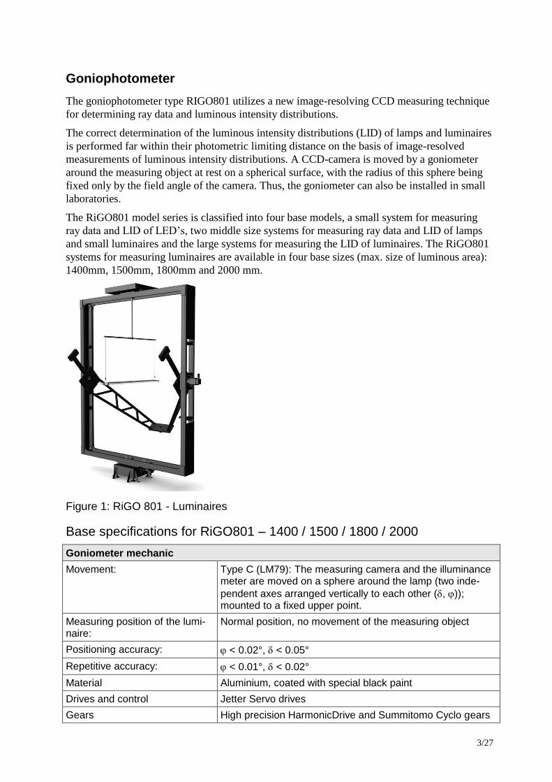
Goniophotometer
The goniophotometer type RIGO801 utilizes a new image-resolving CCD measuring technique
for determining ray data and luminous intensity distributions.
The correct determination of the luminous intensity distributions (LID) of lamps and luminaires
is performed far within their photometric limiting distance on the basis of image-resolved
measurements of luminous intensity distributions. A CCD-camera is moved by a goniometer
around the measuring object at rest on a spherical surface, with the radius of this sphere being
fixed only by the field angle of the camera. Thus, the goniometer can also be installed in small
laboratories.
The RiGO801 model series is classified into four base models, a small system for measuring
ray data and LID of LED’s, two middle size systems for measuring ray data and LID of lamps
and small luminaires and the large systems for measuring the LID of luminaires. The RiGO801
systems for measuring luminaires are available in four base sizes (max. size of luminous area):
1400mm, 1500mm, 1800mm and 2000 mm.
Figure 1: RiGO 801 - Luminaires
Base specifications for RiGO801 – 1400 / 1500 / 1800 / 2000
Goniometer mechanic
Movement: Type C (LM79): The measuring camera and the illuminance meter are moved on a sphere around the lamp (two inde-
pendent axes arranged vertically to each other (, )); mounted to a fixed upper point.
Measuring position of the lumi-naire:
Normal position, no movement of the measuring object
Positioning accuracy: < 0.02°, < 0.05°
Repetitive accuracy: < 0.01°, < 0.02°
Material Aluminium, coated with special black paint
Drives and control Jetter Servo drives
Gears High precision HarmonicDrive and Summitomo Cyclo gears
4/27
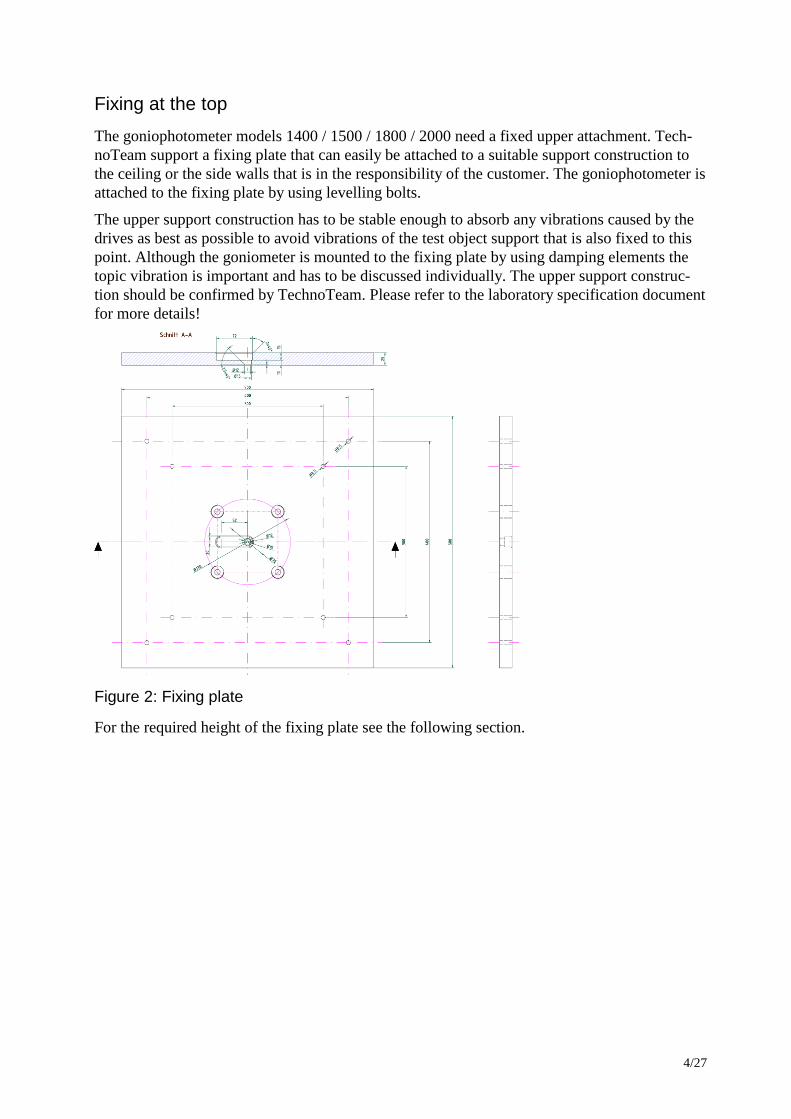
Fixing at the top
The goniophotometer models 1400 / 1500 / 1800 / 2000 need a fixed upper attachment. Tech-
noTeam support a fixing plate that can easily be attached to a suitable support construction to
the ceiling or the side walls that is in the responsibility of the customer. The goniophotometer is
attached to the fixing plate by using levelling bolts.
The upper support construction has to be stable enough to absorb any vibrations caused by the
drives as best as possible to avoid vibrations of the test object support that is also fixed to this
point. Although the goniometer is mounted to the fixing plate by using damping elements the
topic vibration is important and has to be discussed individually. The upper support construc-
tion should be confirmed by TechnoTeam. Please refer to the laboratory specification document
for more details!
Figure 2: Fixing plate
For the required height of the fixing plate see the following section.
5/27
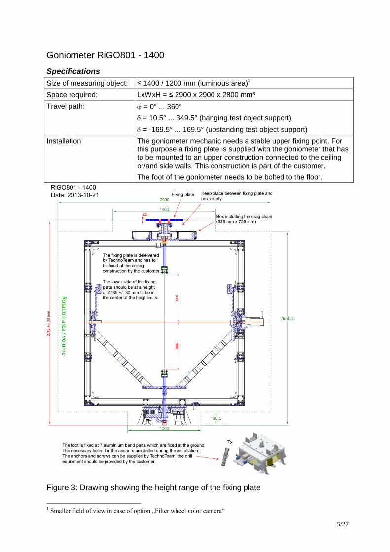
Goniometer RiGO801 - 1400
Specifications
Size of measuring object: ≤ 1400 / 1200 mm (luminous area)1
Space required: LxWxH = ≤ 2900 x 2900 x 2800 mm³
Travel path: = 0° ... 360°
= 10.5° ... 349.5° (hanging test object support)
= -169.5° ... 169.5° (upstanding test object support)
Installation The goniometer mechanic needs a stable upper fixing point. For this purpose a fixing plate is supplied with the goniometer that has to be mounted to an upper construction connected to the ceiling or/and side walls. This construction is part of the customer.
The foot of the goniometer needs to be bolted to the floor.
Figure 3: Drawing showing the height range of the fixing plate
1 Smaller field of view in case of option „Filter wheel color camera“
6/27
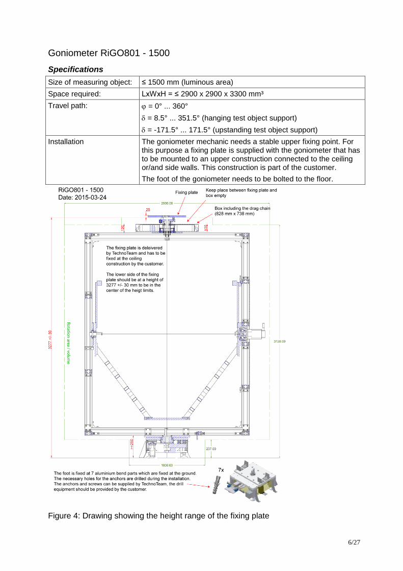
Goniometer RiGO801 - 1500
Specifications
Size of measuring object: ≤ 1500 mm (luminous area)
Space required: LxWxH = ≤ 2900 x 2900 x 3300 mm³
Travel path: = 0° ... 360°
= 8.5° ... 351.5° (hanging test object support)
= -171.5° ... 171.5° (upstanding test object support)
Installation The goniometer mechanic needs a stable upper fixing point. For this purpose a fixing plate is supplied with the goniometer that has to be mounted to an upper construction connected to the ceiling or/and side walls. This construction is part of the customer.
The foot of the goniometer needs to be bolted to the floor.
Figure 4: Drawing showing the height range of the fixing plate
7/27
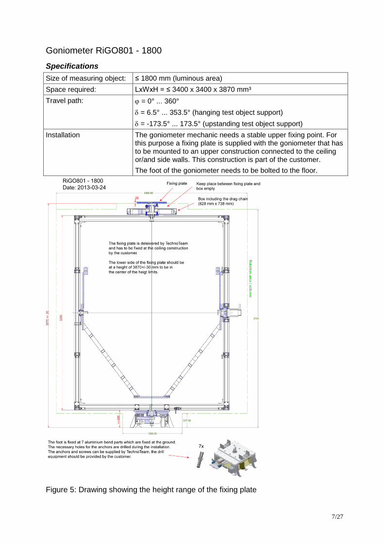
Goniometer RiGO801 - 1800
Specifications
Size of measuring object: ≤ 1800 mm (luminous area)
Space required: LxWxH = ≤ 3400 x 3400 x 3870 mm³
Travel path: = 0° ... 360°
= 6.5° ... 353.5° (hanging test object support)
= -173.5° ... 173.5° (upstanding test object support)
Installation The goniometer mechanic needs a stable upper fixing point. For this purpose a fixing plate is supplied with the goniometer that has to be mounted to an upper construction connected to the ceiling or/and side walls. This construction is part of the customer.
The foot of the goniometer needs to be bolted to the floor.
Figure 5: Drawing showing the height range of the fixing plate
8/27
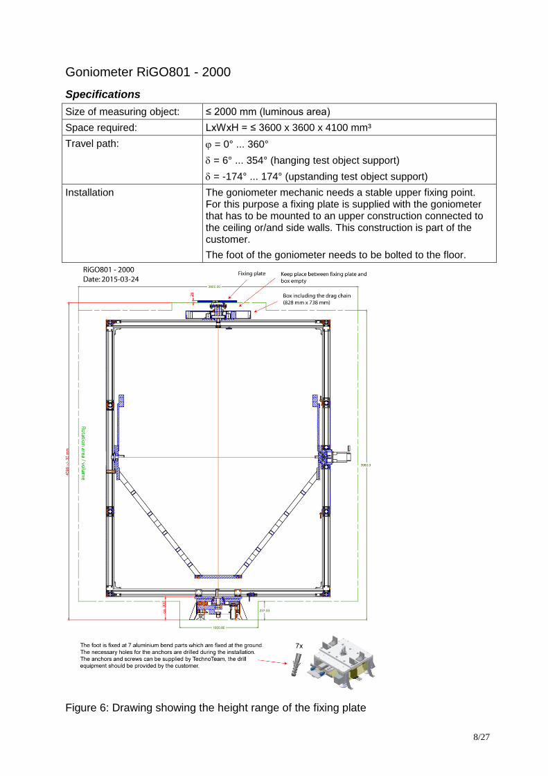
Goniometer RiGO801 - 2000
Specifications
Size of measuring object: ≤ 2000 mm (luminous area)
Space required: LxWxH = ≤ 3600 x 3600 x 4100 mm³
Travel path: = 0° ... 360°
= 6° ... 354° (hanging test object support)
= -174° ... 174° (upstanding test object support)
Installation The goniometer mechanic needs a stable upper fixing point. For this purpose a fixing plate is supplied with the goniometer that has to be mounted to an upper construction connected to the ceiling or/and side walls. This construction is part of the customer.
The foot of the goniometer needs to be bolted to the floor.
Figure 6: Drawing showing the height range of the fixing plate
9/27
Goniometer components
DUT support posts
There are two support posts for attaching the devices under test to. One can be mounted at the
top of the goniometer frame and is hanging. The other can be mounted at the goniometer socket
and is upstanding. Both posts are not moved while the two goniometer axes are moving. Only
one post at time can be used for operating the Goniophotometer.
The electrical connection to the DUT power supply panel is included in the posts in form of a
multi-pole plug at the goniometer attachment side and 5 safety banana plug sockets at the DUT
attachment side.
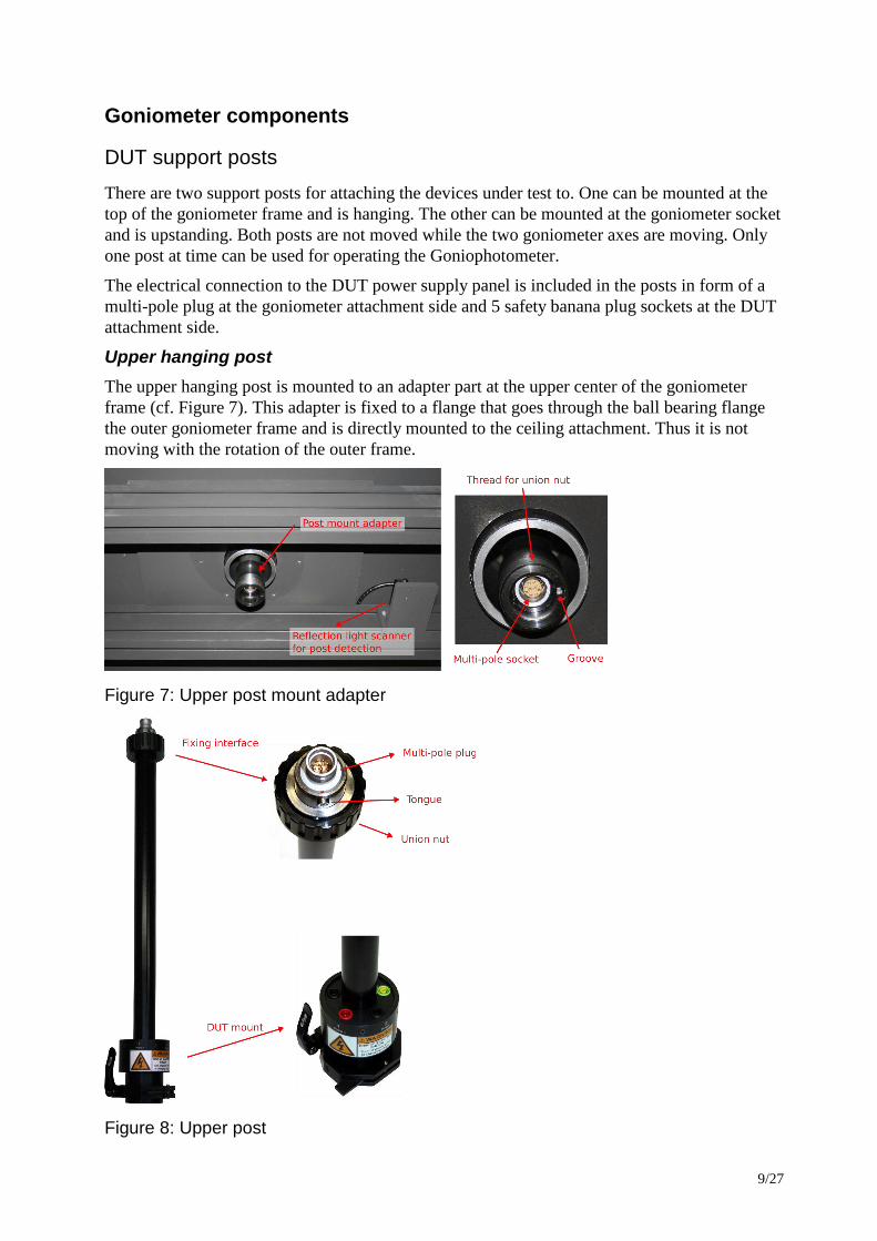
Upper hanging post
The upper hanging post is mounted to an adapter part at the upper center of the goniometer
frame (cf. Figure 7). This adapter is fixed to a flange that goes through the ball bearing flange
the outer goniometer frame and is directly mounted to the ceiling attachment. Thus it is not
moving with the rotation of the outer frame.
Figure 7: Upper post mount adapter
Figure 8: Upper post
10/27
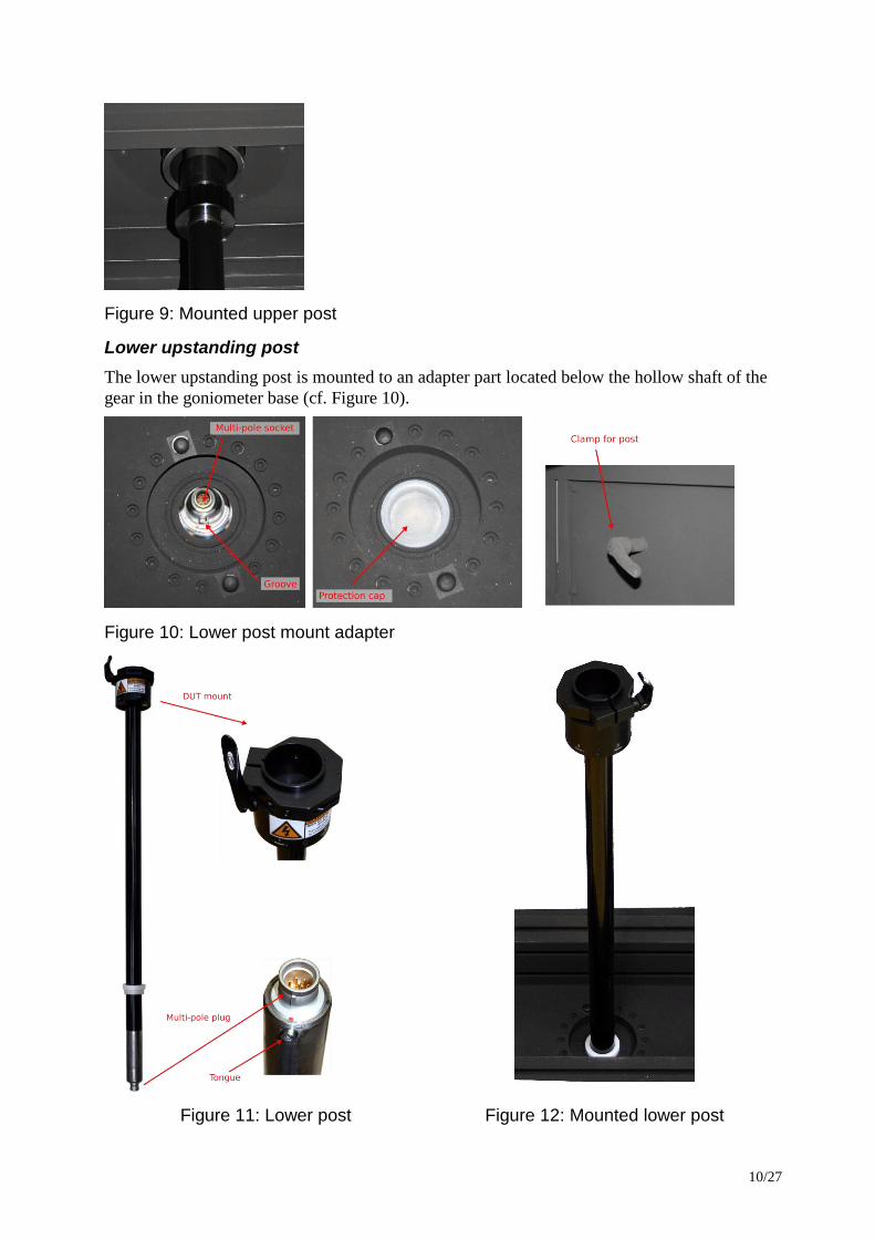
Figure 9: Mounted upper post
Lower upstanding post
The lower upstanding post is mounted to an adapter part located below the hollow shaft of the
gear in the goniometer base (cf. Figure 10).
Figure 10: Lower post mount adapter
Figure 11: Lower post Figure 12: Mounted lower post
11/27
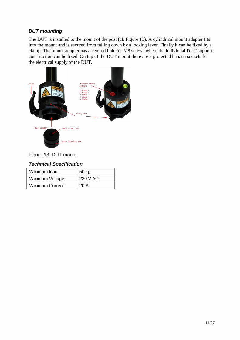
DUT mounting
The DUT is installed to the mount of the post (cf. Figure 13). A cylindrical mount adapter fits
into the mount and is secured from falling down by a locking lever. Finally it can be fixed by a
clamp. The mount adapter has a centred hole for M8 screws where the individual DUT support
construction can be fixed. On top of the DUT mount there are 5 protected banana sockets for
the electrical supply of the DUT.
Figure 13: DUT mount
Technical Specification
Maximum load: 50 kg
Maximum Voltage: 230 V AC
Maximum Current: 20 A
12/27
Measuring device components
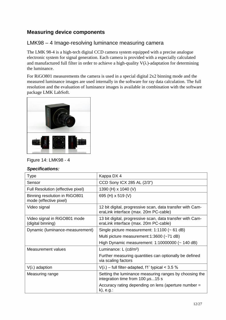
LMK98 – 4 Image-resolving luminance measuring camera
The LMK 98-4 is a high-tech digital CCD camera system equipped with a precise analogue
electronic system for signal generation. Each camera is provided with a especially calculated
and manufactured full filter in order to achieve a high-quality V()-adaptation for determining
the luminance.
For RiGO801 measurements the camera is used in a special digital 2x2 binning mode and the
measured luminance images are used internally in the software for ray data calculation. The full
resolution and the evaluation of luminance images is available in combination with the software
package LMK LabSoft.
Figure 14: LMK98 - 4
Specifications:
Type Kappa DX 4
Sensor CCD Sony ICX 285 AL (2/3")
Full Resolution (effective pixel) 1390 (H) x 1040 (V)
Binning resolution in RiGO801 mode (effective pixel)
695 (H) x 519 (V)
Video signal 12 bit digital, progressive scan, data transfer with Cam-eraLink interface (max. 20m PC-cable)
Video signal in RiGO801 mode (digital binning)
13 bit digital, progressive scan, data transfer with Cam-eraLink interface (max. 20m PC-cable)
Dynamic (luminance-measurement) Single picture measurement: 1:1100 (~ 61 dB)
Multi picture measurement:1:3600 (~71 dB)
High Dynamic measurement: 1:10000000 (~ 140 dB)
Measurement values Luminance: L (cd/m²)
Further measuring quantities can optionally be defined via scaling factors
V() adaption V() – full filter-adapted, f1’ typical < 3.5 %
Measuring range Setting the luminance measuring ranges by choosing the integration time from 100 µs...15 s
Accuracy rating depending on lens (aperture number = k), e.g.:
13/27
1ms ~ 1800 cd/m² & 3s ~ 0.6 cd/m² (k = min.)
1ms ~ 60000 cd/m² & 3s ~ appr. 20 cd/m² (k = max.)
Higher luminances can be achieved using optional neu-tral density filters.
Calibration uncertainty2 fix focused lenses L [ < 2% ]
Repeatability3 L [ < 0.1% ]
Measuring accuracy L [ < 3% (for standard illuminant A) ]
Uniformity L [ < 2% ]
More information available on http://www.technoteam.de
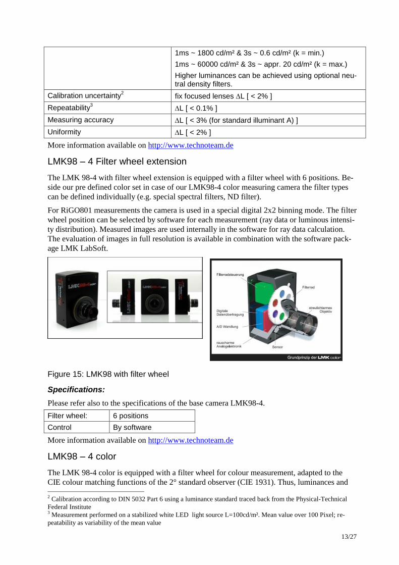
LMK98 – 4 Filter wheel extension
The LMK 98-4 with filter wheel extension is equipped with a filter wheel with 6 positions. Be-
side our pre defined color set in case of our LMK98-4 color measuring camera the filter types
can be defined individually (e.g. special spectral filters, ND filter).
For RiGO801 measurements the camera is used in a special digital 2x2 binning mode. The filter
wheel position can be selected by software for each measurement (ray data or luminous intensi-
ty distribution). Measured images are used internally in the software for ray data calculation.
The evaluation of images in full resolution is available in combination with the software pack-
age LMK LabSoft.
Figure 15: LMK98 with filter wheel
Specifications:
Please refer also to the specifications of the base camera LMK98-4.
Filter wheel: 6 positions
Control By software
More information available on http://www.technoteam.de
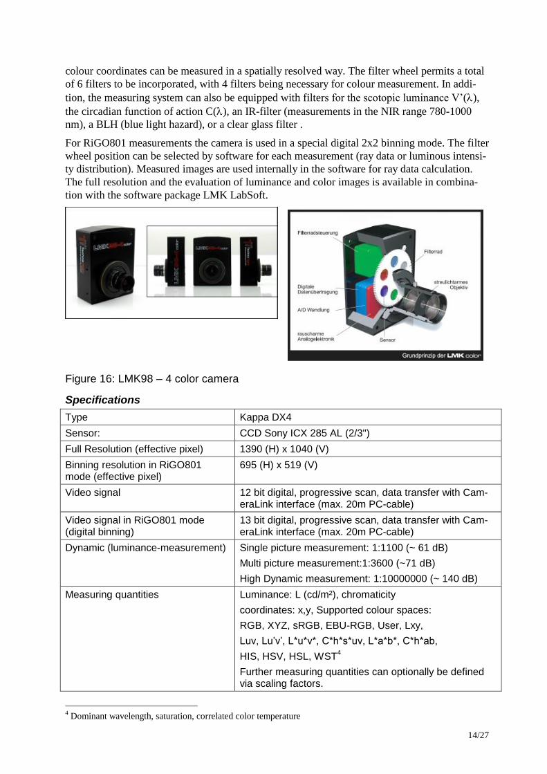
LMK98 – 4 color
The LMK 98-4 color is equipped with a filter wheel for colour measurement, adapted to the
CIE colour matching functions of the 2° standard observer (CIE 1931). Thus, luminances and 2 Calibration according to DIN 5032 Part 6 using a luminance standard traced back from the Physical-Technical
Federal Institute 3 Measurement performed on a stabilized white LED light source L=100cd/m². Mean value over 100 Pixel; re-
peatability as variability of the mean value
14/27
colour coordinates can be measured in a spatially resolved way. The filter wheel permits a total
of 6 filters to be incorporated, with 4 filters being necessary for colour measurement. In addi-
tion, the measuring system can also be equipped with filters for the scotopic luminance V’(),
the circadian function of action C(), an IR-filter (measurements in the NIR range 780-1000
nm), a BLH (blue light hazard), or a clear glass filter .
For RiGO801 measurements the camera is used in a special digital 2x2 binning mode. The filter
wheel position can be selected by software for each measurement (ray data or luminous intensi-
ty distribution). Measured images are used internally in the software for ray data calculation.
The full resolution and the evaluation of luminance and color images is available in combina-
tion with the software package LMK LabSoft.
Figure 16: LMK98 – 4 color camera
Specifications
Type Kappa DX4
Sensor: CCD Sony ICX 285 AL (2/3")
Full Resolution (effective pixel) 1390 (H) x 1040 (V)
Binning resolution in RiGO801 mode (effective pixel)
695 (H) x 519 (V)
Video signal 12 bit digital, progressive scan, data transfer with Cam-eraLink interface (max. 20m PC-cable)
Video signal in RiGO801 mode (digital binning)
13 bit digital, progressive scan, data transfer with Cam-eraLink interface (max. 20m PC-cable)
Dynamic (luminance-measurement) Single picture measurement: 1:1100 (~ 61 dB)
Multi picture measurement:1:3600 (~71 dB)
High Dynamic measurement: 1:10000000 (~ 140 dB)
Measuring quantities Luminance: L (cd/m²), chromaticity
coordinates: x,y, Supported colour spaces:
RGB, XYZ, sRGB, EBU-RGB, User, Lxy,
Luv, Lu’v’, L*u*v*, C*h*s*uv, L*a*b*, C*h*ab,
HIS, HSV, HSL, WST4
Further measuring quantities can optionally be defined via scaling factors.
4 Dominant wavelength, saturation, correlated color temperature
15/27
Filter wheel 6 positions (x1, x2, y, z, glass, user defined)
V() adaption V() – full filter-adapted, f1’ typical < 3.5 %
Measuring range Setting the luminance measuring ranges by choosing the integration time from 100 µs...15 s
Accuracy rating depending on lens (aperture number = k), e.g.:
1ms ~ 1800 cd/m² & 3s ~ 0.6 cd/m² (k = min.)
1ms ~ 60000 cd/m² & 3s ~ appr. 20 cd/m² (k = max.)
Higher luminances can be achieved using optional neu-tral density filters.
Calibration uncertainty5 fix focused lenses L [ < 2% ]
Repeatability6 L [ < 0.1% ]
x,y [ < 0,0001 ]
Measuring accuracy L [ < 3% (for standard illuminant A) ]
x,y [ < 0.0020 (for standard illuminant A) ]
x,y [ < 0.0100 (set of test colours)]7
Uniformity L [ < 2% ]
More information available on http://www.technoteam.de
Optical Lens TT 4.2
Focal length: 4.2 mm
Aperture angle: ~ 90 deg
Photometrically corrected (shading / flat-field)
Distortion-corrected
Optical Lens TT 8
Focal length: 8 mm
Aperture angle: ~26 deg
Photometrically corrected (shading / flat-field)
Distortion-corrected
Optical Lens TT 25
Focal length: 25 mm
Aperture angle: ~14 deg
Photometrically corrected (shading / flat-field)
Distortion-corrected
This optical lens is used for the adaption to smaller test objects
5 Calibration according to DIN 5032 Part 6 using a luminance standard traced back from the Physical-Technical
Federal Institute 6 Measurement performed on a stabilized white LED light source L=100cd/m². Mean value over 100 Pixel; re-
peatability as variability of the mean value 7 Measured value based on 30 test colors with different spectral distributions based on ROSCO color filters
16/27
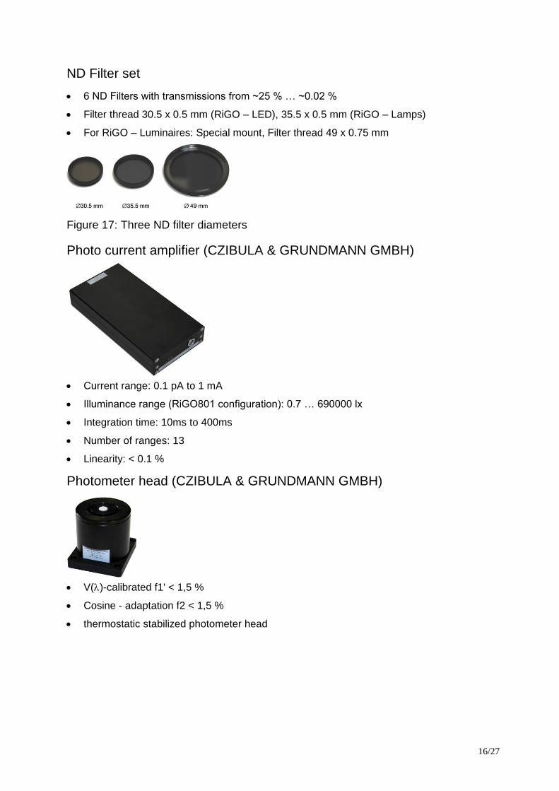
ND Filter set
6 ND Filters with transmissions from ~25 % … ~0.02 %
Filter thread 30.5 x 0.5 mm (RiGO – LED), 35.5 x 0.5 mm (RiGO – Lamps)
For RiGO – Luminaires: Special mount, Filter thread 49 x 0.75 mm
Figure 17: Three ND filter diameters
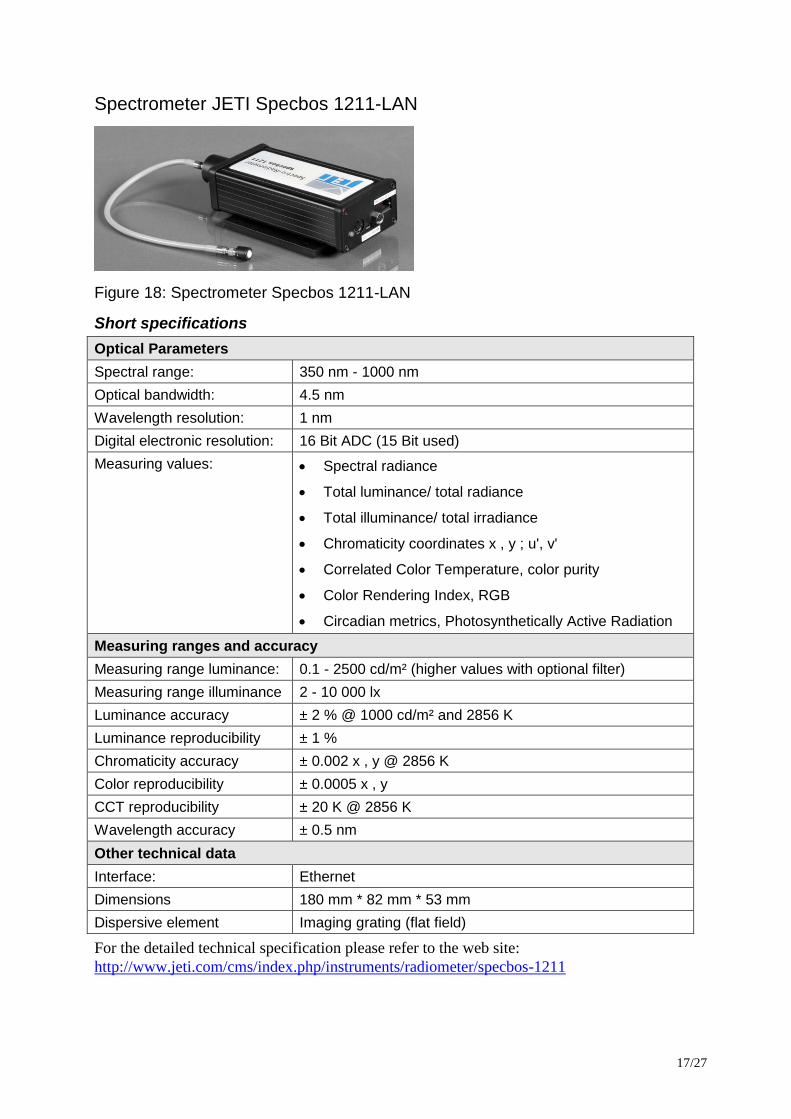
Photo current amplifier (CZIBULA & GRUNDMANN GMBH)
Current range: 0.1 pA to 1 mA
Illuminance range (RiGO801 configuration): 0.7 … 690000 lx
Integration time: 10ms to 400ms
Number of ranges: 13
Linearity: < 0.1 %
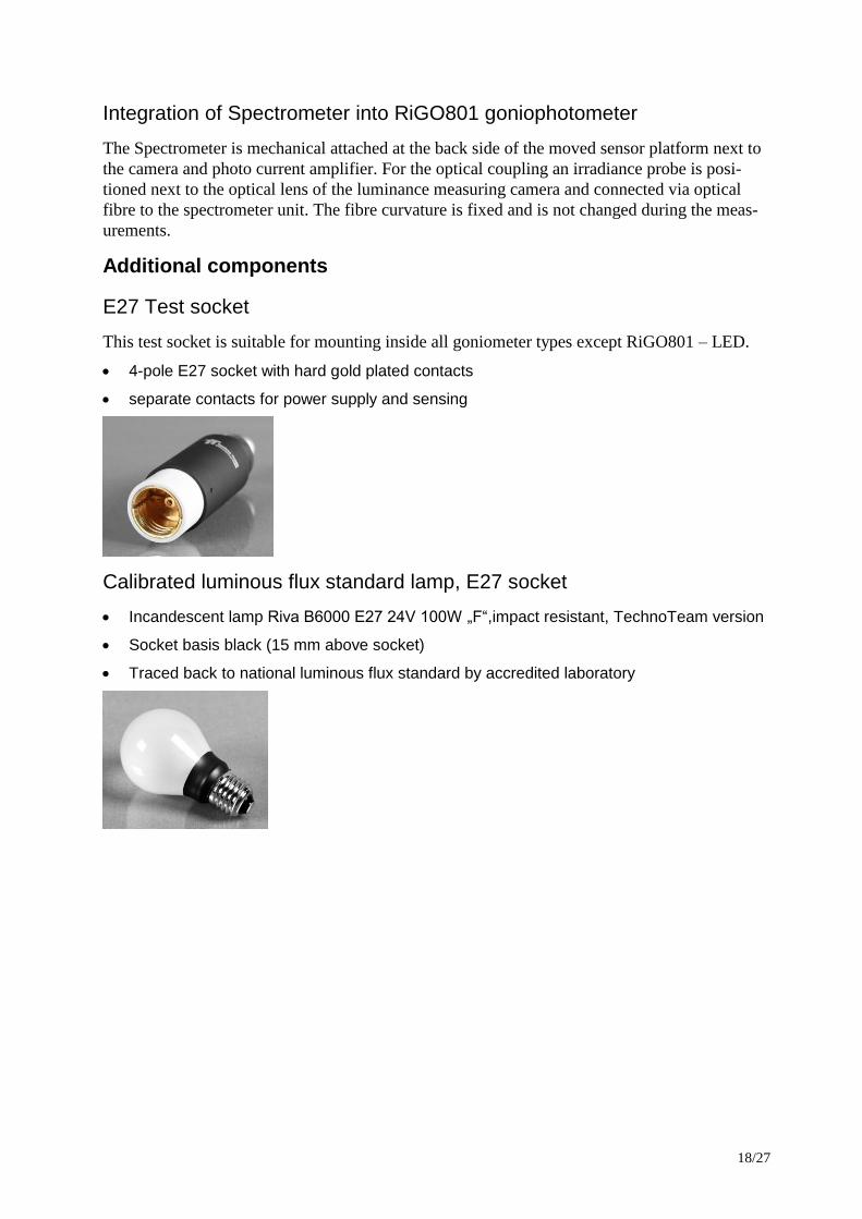
Photometer head (CZIBULA & GRUNDMANN GMBH)
V()-calibrated f1' < 1,5 %
Cosine - adaptation f2 < 1,5 %
thermostatic stabilized photometer head
17/27
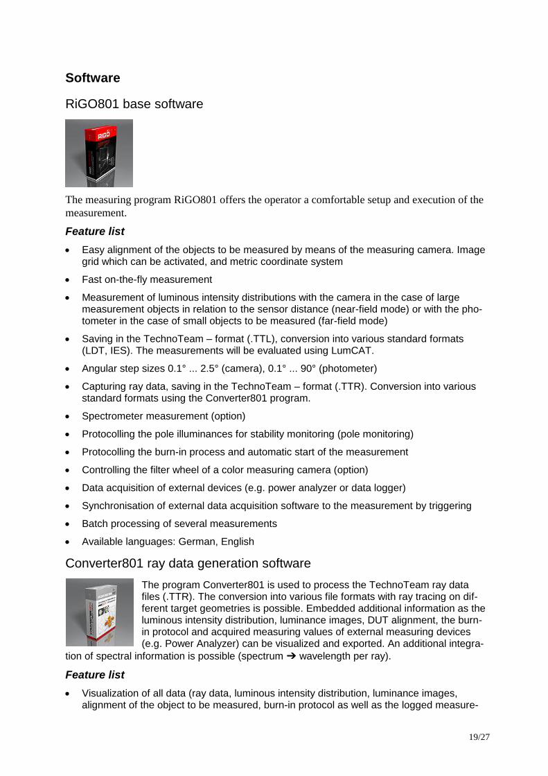
Spectrometer JETI Specbos 1211-LAN
Figure 18: Spectrometer Specbos 1211-LAN
Short specifications
Optical Parameters
Spectral range: 350 nm - 1000 nm
Optical bandwidth: 4.5 nm
Wavelength resolution: 1 nm
Digital electronic resolution: 16 Bit ADC (15 Bit used)
Measuring values: Spectral radiance
Total luminance/ total radiance
Total illuminance/ total irradiance
Chromaticity coordinates x , y ; u', v'
Correlated Color Temperature, color purity
Color Rendering Index, RGB
Circadian metrics, Photosynthetically Active Radiation
Measuring ranges and accuracy
Measuring range luminance: 0.1 - 2500 cd/m² (higher values with optional filter)
Measuring range illuminance 2 - 10 000 lx
Luminance accuracy ± 2 % @ 1000 cd/m² and 2856 K
Luminance reproducibility ± 1 %
Chromaticity accuracy ± 0.002 x , y @ 2856 K
Color reproducibility ± 0.0005 x , y
CCT reproducibility ± 20 K @ 2856 K
Wavelength accuracy ± 0.5 nm
Other technical data
Interface: Ethernet
Dimensions 180 mm * 82 mm * 53 mm
Dispersive element Imaging grating (flat field)
For the detailed technical specification please refer to the web site:
http://www.jeti.com/cms/index.php/instruments/radiometer/specbos-1211
18/27
Integration of Spectrometer into RiGO801 goniophotometer
The Spectrometer is mechanical attached at the back side of the moved sensor platform next to
the camera and photo current amplifier. For the optical coupling an irradiance probe is posi-
tioned next to the optical lens of the luminance measuring camera and connected via optical
fibre to the spectrometer unit. The fibre curvature is fixed and is not changed during the meas-
urements.
Additional components
E27 Test socket
This test socket is suitable for mounting inside all goniometer types except RiGO801 – LED.
4-pole E27 socket with hard gold plated contacts
separate contacts for power supply and sensing
Calibrated luminous flux standard lamp, E27 socket
Incandescent lamp Riva B6000 E27 24V 100W „F“,impact resistant, TechnoTeam version
Socket basis black (15 mm above socket)
Traced back to national luminous flux standard by accredited laboratory
19/27
Software
RiGO801 base software
The measuring program RiGO801 offers the operator a comfortable setup and execution of the
measurement.
Feature list
Easy alignment of the objects to be measured by means of the measuring camera. Image grid which can be activated, and metric coordinate system
Fast on-the-fly measurement
Measurement of luminous intensity distributions with the camera in the case of large measurement objects in relation to the sensor distance (near-field mode) or with the pho-tometer in the case of small objects to be measured (far-field mode)
Saving in the TechnoTeam – format (.TTL), conversion into various standard formats (LDT, IES). The measurements will be evaluated using LumCAT.
Angular step sizes 0.1° ... 2.5° (camera), 0.1° ... 90° (photometer)
Capturing ray data, saving in the TechnoTeam – format (.TTR). Conversion into various standard formats using the Converter801 program.
Spectrometer measurement (option)
Protocolling the pole illuminances for stability monitoring (pole monitoring)
Protocolling the burn-in process and automatic start of the measurement
Controlling the filter wheel of a color measuring camera (option)
Data acquisition of external devices (e.g. power analyzer or data logger)
Synchronisation of external data acquisition software to the measurement by triggering
Batch processing of several measurements
Available languages: German, English
Converter801 ray data generation software
The program Converter801 is used to process the TechnoTeam ray data files (.TTR). The conversion into various file formats with ray tracing on dif-ferent target geometries is possible. Embedded additional information as the luminous intensity distribution, luminance images, DUT alignment, the burn-in protocol and acquired measuring values of external measuring devices (e.g. Power Analyzer) can be visualized and exported. An additional integra-
tion of spectral information is possible (spectrum ➔ wavelength per ray).
Feature list
Visualization of all data (ray data, luminous intensity distribution, luminance images, alignment of the object to be measured, burn-in protocol as well as the logged measure-
20/27
ment data of external devices such as power analyzer) contained in TechnoTeam ray files (.TTR).
Generation of various ray data formats (ASAP, Optis, LightTools, LucidShape, Zemax, TracePro, SimuLux, Photopia)
Raytracing to basic geometries (sphere, cylinder, cuboid)
Rotation and displacement of the ray data
Integration of spectral information possible (spectrum ➔ wavelength per ray)
Recalculation of the luminous intensity distribution in other angular resolutions
Output of the luminous intensity distribution in various formats (EULUMDAT, IES)
Provision of customized formats possible
Batch processing of conversion processes
API for accessing the TechnoTeam ray data format
Available languages: German, English
This software is free of license fees and can be used without any restrictions and transferred to
any ray data users.
LumCAT
LUMCat is a database, which allows the management of photometric data
together with all product properties like texts, images etc due to a relational
database-table system. Also it includes editors for the intensity distribution
which allows modification in many different ways.
The LumCAT license allows the installation on more than one evaluation
computer of the same customer.
Feature list
Support for TechnoTeam measurement data files (*.TTL), EULUM-DAT, TM14, IES, Cal-culux
System for managing and processing luminaire data
Integrated relational database, realized as standard ACCES-DB version
Modification of all product information
Tabular processing of the luminous intensity distribution
Function for turning, inclining and swivelling the luminous intensity distributions
Modification of the operating efficiency ratio (scaling)
Multiple processing function for loading information, dimensions, manufacturer and article names
Photometric product valuation in the form of a print-out or as WMF-file
Output of the luminous intensity distribution (polar, cartesian, cone diagram)
Output of the illumination efficiency ratios
Glare evaluation according to Söllner and UGR
Isolux diagrams
Illumination efficiency ratios according to LiTG Publ. 3.5
21/27
Available languages: German, English
LMK LabSoft luminance measuring software (full version)
The LMK LabSoft is a laboratory software package that offers a variety of
functions for capturing and evaluating luminance and for instance color
images. LabSoft is bundled with the measuring camera LMK98-4 and the
calibration data set.
Specification
Image capture
Live image
Exposure adjustment
‘SinglePic’-image
’MultiPic’-image
’HighDyn’-image
Capturing modulated light
Live Luminance and Live HighDyn
Capturing measurement series (manual, time controlled, mechanical controlled)
Representation of images (Pseudo-colours, ISO colours, scaling)
Working with images (load, save, delete, copy, print)
Displaying measuring values by means of cursors (standard, rectangle, circle, line, circu-lar ring, cross, zoom)
Measurement regions (load, save, copy, paste, group, print)
Measuring value indication using inspectors
Standard statistics (standard evaluation, histogram, sectional view, time statistics, lumi-nance object, integral object, symbol object, arc object, filament object)
Report function (create, load, save, print)
Evaluation images and image processing
Unlimited evaluation images
Physical parameters and units
Assigning list of regions
Assigning image tab windows
Image arithmetics
Coordinate transformation
Projective rectification - orthophotographs
ISO lines in luminance images
Automation via TCL-Macro
Recording of TCL - Macros
Running of TCL - Macros
Further information is also available on http://www.technoteam.de.
22/27
LMK LabSoft color extension
Specification
The color specific functions are only available in combination with a LMK98 – 4 color camera.
Image capture
Color ’HighDyn’-image
Colour images and colour metrics
Colour space and measuring values
Calculation of colour differences
Decomposition of colour images into colour extract images
Composition of colour extract images into colour images
Test colour images
Measurement protocols (create, load, save, comments)
Further information is also available on http://www.technoteam.de.
LMK LabSoft ActiveX extension
Using the LMK LabSoft as ActiveX control allows the development of own software to com-
mand each function from a suitable programming software (e.g. LabView).
Specification
Active X
Active X programming interface
Further information is also available on http://www.technoteam.de.
23/27
Switching cabinet components
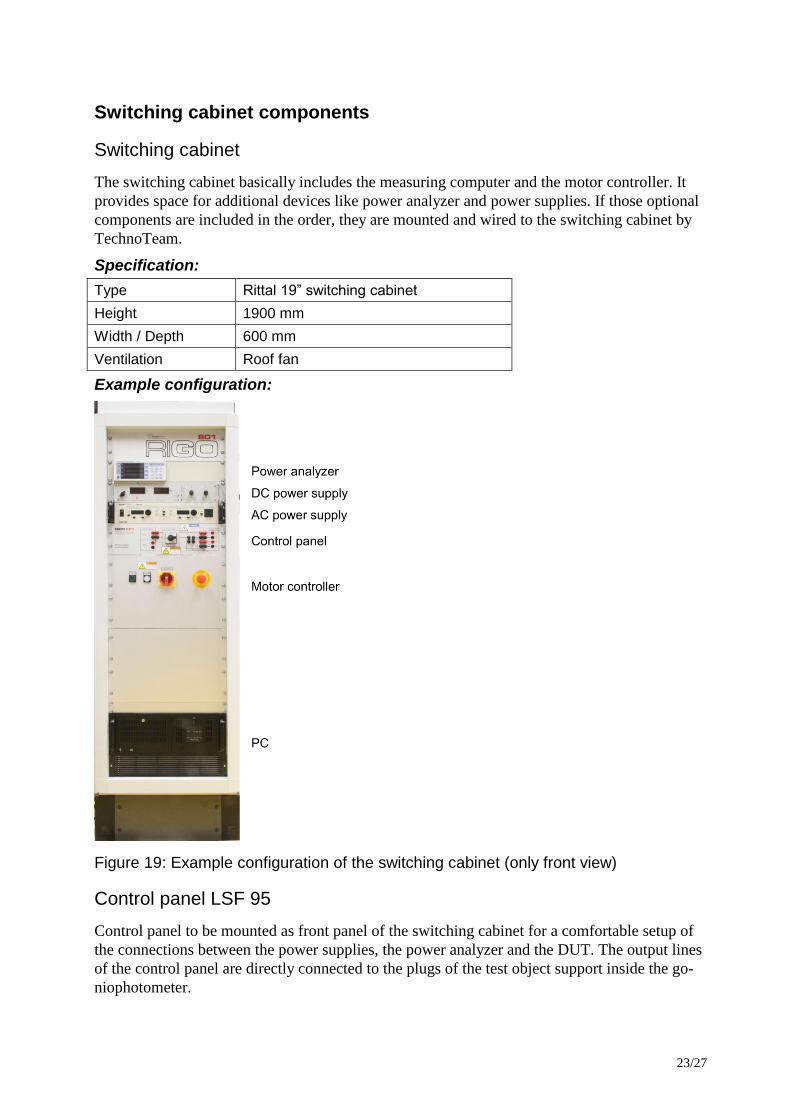
Switching cabinet
The switching cabinet basically includes the measuring computer and the motor controller. It
provides space for additional devices like power analyzer and power supplies. If those optional
components are included in the order, they are mounted and wired to the switching cabinet by
TechnoTeam.
Specification:
Type Rittal 19” switching cabinet
Height 1900 mm
Width / Depth 600 mm
Ventilation Roof fan
Example configuration:
Figure 19: Example configuration of the switching cabinet (only front view)
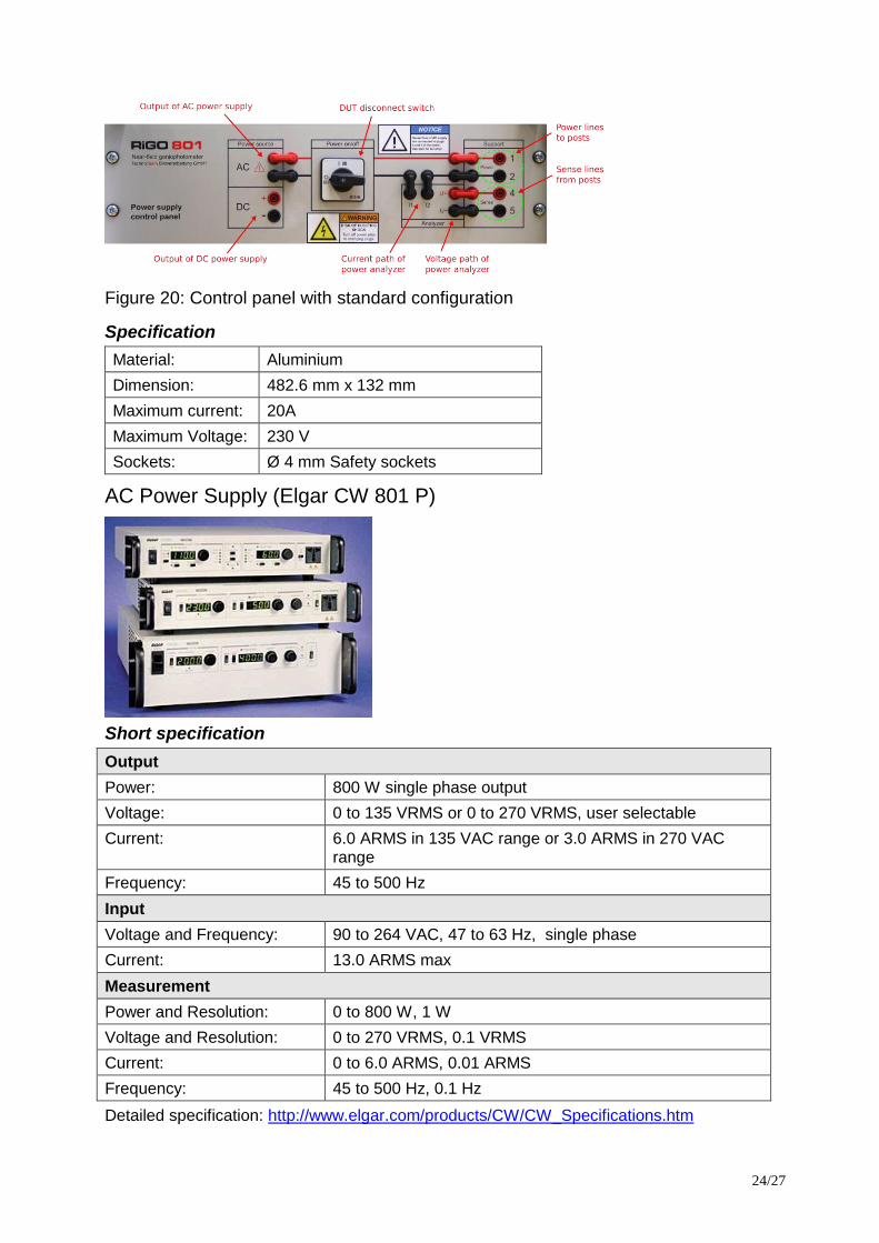
Control panel LSF 95
Control panel to be mounted as front panel of the switching cabinet for a comfortable setup of
the connections between the power supplies, the power analyzer and the DUT. The output lines
of the control panel are directly connected to the plugs of the test object support inside the go-
niophotometer.
24/27
Figure 20: Control panel with standard configuration
Specification
Material: Aluminium
Dimension: 482.6 mm x 132 mm
Maximum current: 20A
Maximum Voltage: 230 V
Sockets: Ø 4 mm Safety sockets
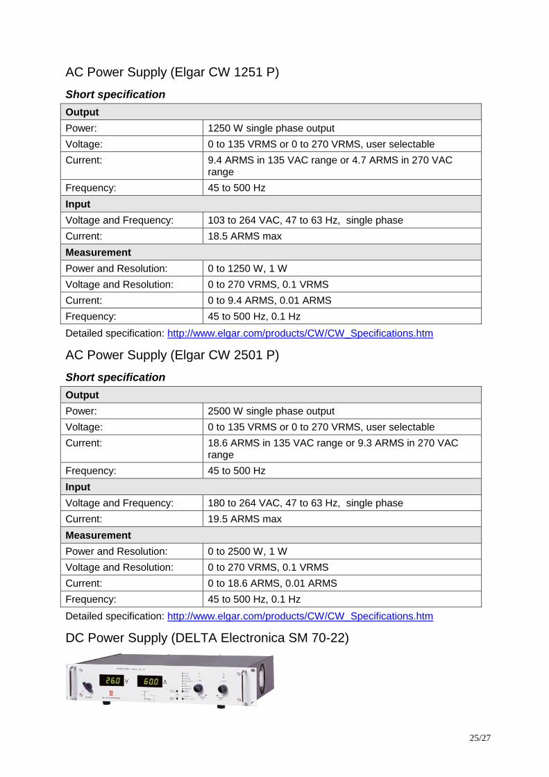
AC Power Supply (Elgar CW 801 P)
Short specification
Output
Power: 800 W single phase output
Voltage: 0 to 135 VRMS or 0 to 270 VRMS, user selectable
Current: 6.0 ARMS in 135 VAC range or 3.0 ARMS in 270 VAC range
Frequency: 45 to 500 Hz
Input
Voltage and Frequency: 90 to 264 VAC, 47 to 63 Hz, single phase
Current: 13.0 ARMS max
Measurement
Power and Resolution: 0 to 800 W, 1 W
Voltage and Resolution: 0 to 270 VRMS, 0.1 VRMS
Current: 0 to 6.0 ARMS, 0.01 ARMS
Frequency: 45 to 500 Hz, 0.1 Hz
Detailed specification: http://www.elgar.com/products/CW/CW_Specifications.htm
25/27
AC Power Supply (Elgar CW 1251 P)
Short specification
Output
Power: 1250 W single phase output
Voltage: 0 to 135 VRMS or 0 to 270 VRMS, user selectable
Current: 9.4 ARMS in 135 VAC range or 4.7 ARMS in 270 VAC range
Frequency: 45 to 500 Hz
Input
Voltage and Frequency: 103 to 264 VAC, 47 to 63 Hz, single phase
Current: 18.5 ARMS max
Measurement
Power and Resolution: 0 to 1250 W, 1 W
Voltage and Resolution: 0 to 270 VRMS, 0.1 VRMS
Current: 0 to 9.4 ARMS, 0.01 ARMS
Frequency: 45 to 500 Hz, 0.1 Hz
Detailed specification: http://www.elgar.com/products/CW/CW_Specifications.htm
AC Power Supply (Elgar CW 2501 P)
Short specification
Output
Power: 2500 W single phase output
Voltage: 0 to 135 VRMS or 0 to 270 VRMS, user selectable
Current: 18.6 ARMS in 135 VAC range or 9.3 ARMS in 270 VAC range
Frequency: 45 to 500 Hz
Input
Voltage and Frequency: 180 to 264 VAC, 47 to 63 Hz, single phase
Current: 19.5 ARMS max
Measurement
Power and Resolution: 0 to 2500 W, 1 W
Voltage and Resolution: 0 to 270 VRMS, 0.1 VRMS
Current: 0 to 18.6 ARMS, 0.01 ARMS
Frequency: 45 to 500 Hz, 0.1 Hz
Detailed specification: http://www.elgar.com/products/CW/CW_Specifications.htm
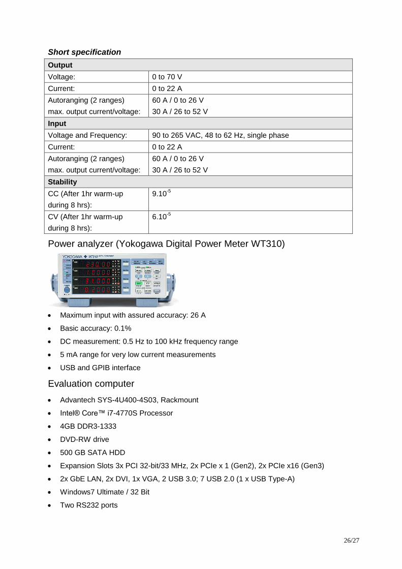
DC Power Supply (DELTA Electronica SM 70-22)
26/27
Short specification
Output
Voltage: 0 to 70 V
Current: 0 to 22 A
Autoranging (2 ranges)
max. output current/voltage:
60 A / 0 to 26 V
30 A / 26 to 52 V
Input
Voltage and Frequency: 90 to 265 VAC, 48 to 62 Hz, single phase
Current: 0 to 22 A
Autoranging (2 ranges)
max. output current/voltage:
60 A / 0 to 26 V
30 A / 26 to 52 V
Stability
CC (After 1hr warm-up
during 8 hrs):
9.10-5
CV (After 1hr warm-up
during 8 hrs):
6.10-5
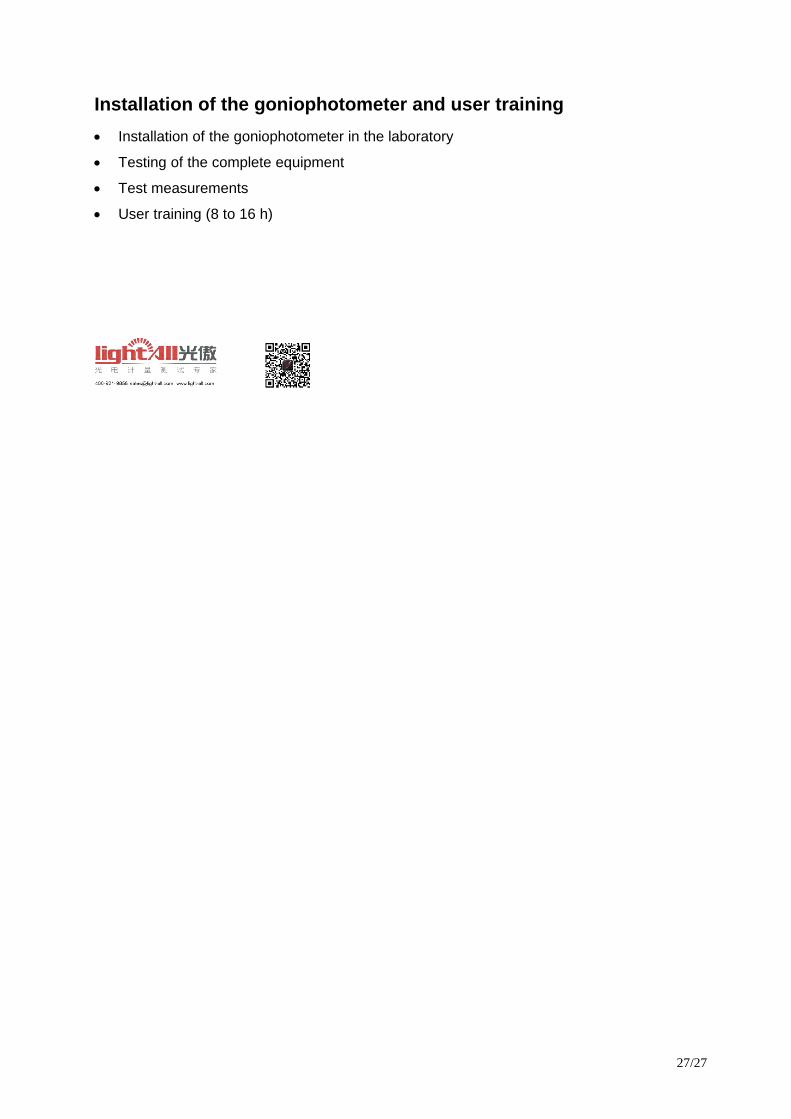
Power analyzer (Yokogawa Digital Power Meter WT310)
Maximum input with assured accuracy: 26 A
Basic accuracy: 0.1%
DC measurement: 0.5 Hz to 100 kHz frequency range
5 mA range for very low current measurements
USB and GPIB interface
Evaluation computer
Advantech SYS-4U400-4S03, Rackmount
Intel® Core™ i7-4770S Processor
4GB DDR3-1333
DVD-RW drive
500 GB SATA HDD
Expansion Slots 3x PCI 32-bit/33 MHz, 2x PCIe x 1 (Gen2), 2x PCIe x16 (Gen3)
2x GbE LAN, 2x DVI, 1x VGA, 2 USB 3.0; 7 USB 2.0 (1 x USB Type-A)
Windows7 Ultimate / 32 Bit
Two RS232 ports
27/27
Installation of the goniophotometer and user training
Installation of the goniophotometer in the laboratory
Testing of the complete equipment
Test measurements
User training (8 to 16 h)