Embed Size (px)
Citation preview
2015-01-16 1
2015-01-16
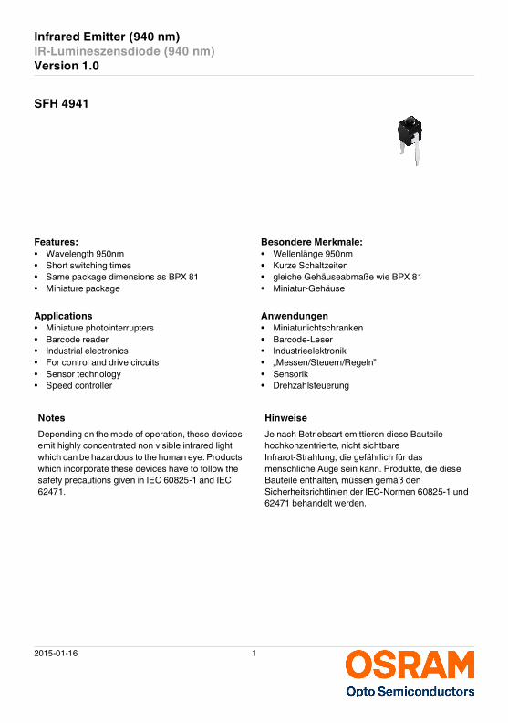
Infrared Emitter (940 nm)
IR-Lumineszensdiode (940 nm)
Version 1.0
SFH 4941
Features: Besondere Merkmale:
• Wavelength 950nm • Wellenlänge 950nm• Short switching times • Kurze Schaltzeiten• Same package dimensions as BPX 81 • gleiche Gehäuseabmaße wie BPX 81• Miniature package • Miniatur-Gehäuse
Applications Anwendungen
• Miniature photointerrupters • Miniaturlichtschranken• Barcode reader • Barcode-Leser• Industrial electronics • Industrieelektronik• For control and drive circuits • „Messen/Steuern/Regeln”• Sensor technology • Sensorik• Speed controller • Drehzahlsteuerung
Notes Hinweise
Depending on the mode of operation, these devices emit highly concentrated non visible infrared light which can be hazardous to the human eye. Products which incorporate these devices have to follow the safety precautions given in IEC 60825-1 and IEC 62471.
Je nach Betriebsart emittieren diese Bauteile hochkonzentrierte, nicht sichtbare Infrarot-Strahlung, die gefährlich für das menschliche Auge sein kann. Produkte, die diese Bauteile enthalten, müssen gemäß den Sicherheitsrichtlinien der IEC-Normen 60825-1 und 62471 behandelt werden.
2015-01-16 2
Version 1.0 SFH 4941
Ordering Information
Bestellinformation
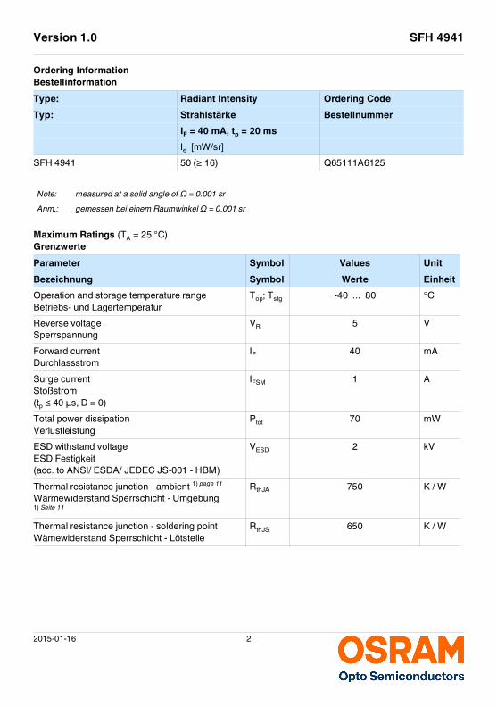
Maximum Ratings (TA = 25 °C)Grenzwerte
Type: Radiant Intensity Ordering Code
Typ: Strahlstärke Bestellnummer
IF = 40 mA, tp = 20 ms
Ie [mW/sr]
SFH 4941 50 (≥ 16) Q65111A6125
Note: measured at a solid angle of Ω = 0.001 sr
Anm.: gemessen bei einem Raumwinkel Ω = 0.001 sr
Parameter Symbol Values Unit
Bezeichnung Symbol Werte Einheit
Operation and storage temperature rangeBetriebs- und Lagertemperatur
Top; Tstg -40 ... 80 °C
Reverse voltageSperrspannung
VR 5 V
Forward currentDurchlassstrom
IF 40 mA
Surge currentStoßstrom(tp ≤ 40 µs, D = 0)
IFSM 1 A
Total power dissipationVerlustleistung
Ptot 70 mW
ESD withstand voltageESD Festigkeit(acc. to ANSI/ ESDA/ JEDEC JS-001 - HBM)
VESD 2 kV
Thermal resistance junction - ambient 1) page 11
Wärmewiderstand Sperrschicht - Umgebung 1) Seite 11
RthJA 750 K / W
Thermal resistance junction - soldering point
Wämewiderstand Sperrschicht - Lötstelle RthJS 650 K / W
Version 1.0 SFH 4941
2015-01-16 3
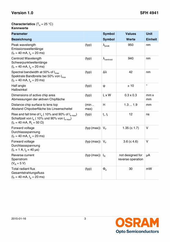
Characteristics (TA = 25 °C)Kennwerte
Parameter Symbol Values Unit
Bezeichnung Symbol Werte Einheit
Peak wavelengthEmissionswellenlänge(IF = 40 mA, tp = 20 ms)
(typ) λpeak 950 nm
Centroid WavelengthSchwerpunktwellenlänge(IF = 40 mA, tp = 20 ms)
(typ) λcentroid 940 nm
Spectral bandwidth at 50% of Imax
Spektrale Bandbreite bei 50% von Imax
(IF = 40 mA, tp = 20 ms)
(typ) ∆λ 42 nm
Half angleHalbwinkel
(typ) ϕ ± 10 °
Dimensions of active chip areaAbmessungen der aktiven Chipfläche
(typ) L x W 0.3 x 0.3 mm x mm
Distance chip surface to lens topAbstand Chipoberfläche bis Linsenscheitel
(min .. max)
H 1.3 ... 1.9 mm
Rise and fall time of Ie ( 10% and 90% of Ie max)Schaltzeit von Ie ( 10% und 90% von Ie max)(IF = 40 mA, RL = 50 Ω)
(typ) tr, tf 12 ns
Forward voltageDurchlassspannung(IF = 40 mA, tp = 20 ms)
(typ (max)) VF 1.35 (≤ 1.7) V
Forward voltageDurchlassspannung(IF = 1 A, tp = 40 µs)
(typ (max)) VF 3.6 (≤ 4.6) V
Reverse currentSperrstrom(VR = 5 V)
(typ (max)) IR not designed for reverse operation
µA
Total radiant fluxGesamtstrahlungsfluss(IF = 40 mA, tp = 20 ms)
(typ) Φe 30 mW
2015-01-16 4
Version 1.0 SFH 4941
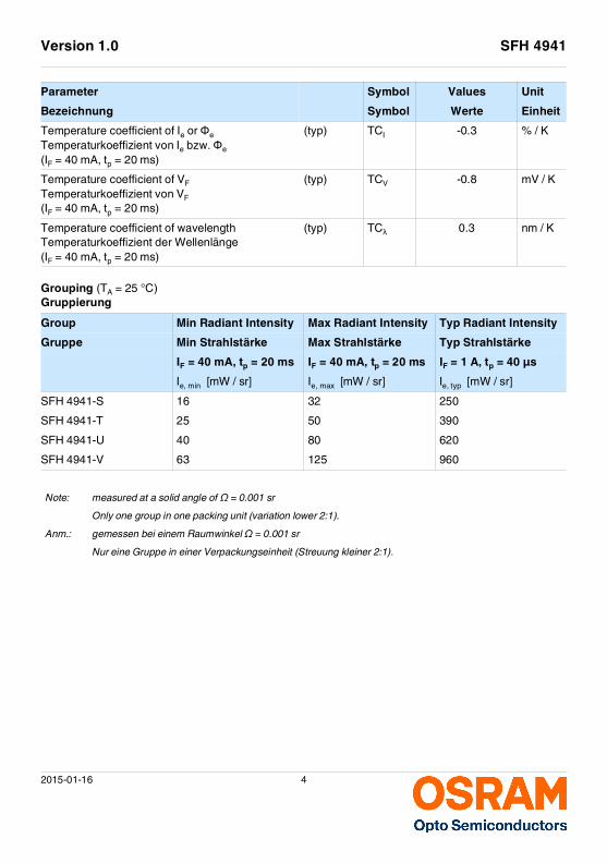
Grouping (TA = 25 °C)Gruppierung
Temperature coefficient of Ie or Φe
Temperaturkoeffizient von Ie bzw. Φe
(IF = 40 mA, tp = 20 ms)
(typ) TCI -0.3 % / K
Temperature coefficient of VF
Temperaturkoeffizient von VF
(IF = 40 mA, tp = 20 ms)
(typ) TCV -0.8 mV / K
Temperature coefficient of wavelengthTemperaturkoeffizient der Wellenlänge(IF = 40 mA, tp = 20 ms)
(typ) TCλ 0.3 nm / K
Group Min Radiant Intensity Max Radiant Intensity Typ Radiant Intensity
Gruppe Min Strahlstärke Max Strahlstärke Typ Strahlstärke
IF = 40 mA, tp = 20 ms IF = 40 mA, tp = 20 ms IF = 1 A, tp = 40 µs
Ie, min [mW / sr] Ie, max [mW / sr] Ie, typ [mW / sr]
SFH 4941-S 16 32 250
SFH 4941-T 25 50 390
SFH 4941-U 40 80 620
SFH 4941-V 63 125 960
Note: measured at a solid angle of Ω = 0.001 sr
Only one group in one packing unit (variation lower 2:1).
Anm.: gemessen bei einem Raumwinkel Ω = 0.001 sr
Nur eine Gruppe in einer Verpackungseinheit (Streuung kleiner 2:1).
Parameter Symbol Values Unit
Bezeichnung Symbol Werte Einheit
Version 1.0 SFH 4941
2015-01-16 5
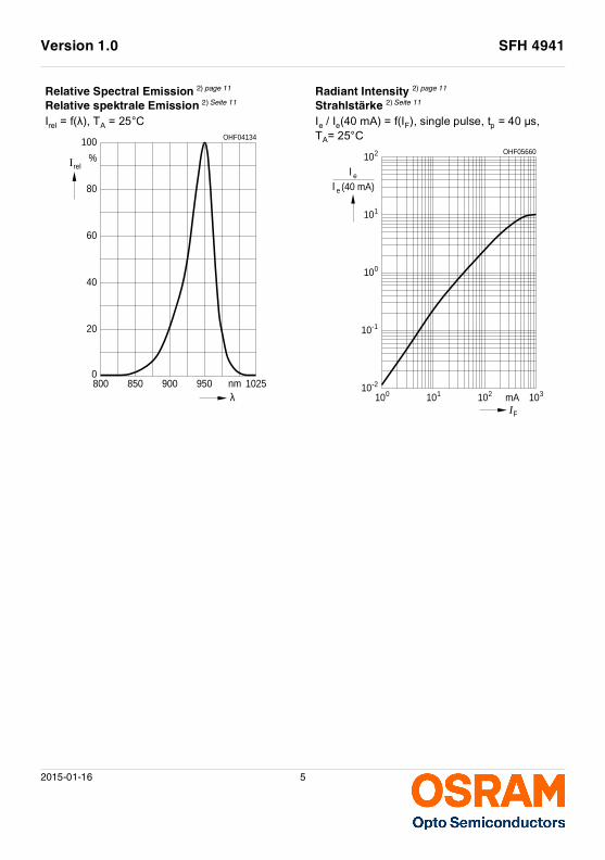
Relative Spectral Emission 2) page 11
Relative spektrale Emission 2) Seite 11
Irel = f(λ), TA = 25°C
Radiant Intensity 2) page 11
Strahlstärke 2) Seite 11
Ie / Ie(40 mA) = f(IF), single pulse, tp = 40 µs, TA= 25°C
8000
nm
%
OHF04134
20
40
60
80
100
Irel
λ850 900 950 1025
OHF05660
310
Ιe
(40 mA)e
Ι
FI102110100 mA
10-2
10-1
100
101
210
2015-01-16 6
Version 1.0 SFH 4941
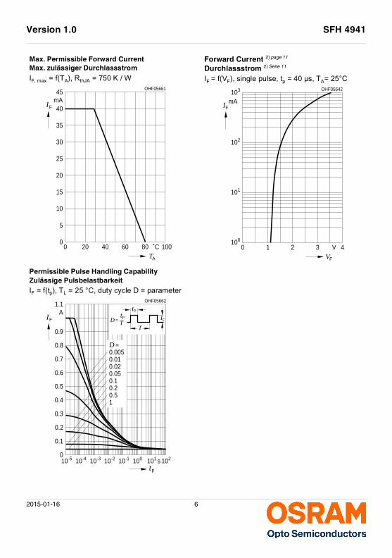
Max. Permissible Forward Current
Max. zulässiger Durchlassstrom
IF, max = f(TA), RthJA = 750 K / W
Forward Current 2) page 11
Durchlassstrom 2) Seite 11
IF = f(VF), single pulse, tp = 40 µs, TA= 25°C
Permissible Pulse Handling Capability
Zulässige Pulsbelastbarkeit
IF = f(tp), TL = 25 °C, duty cycle D = parameter
00
˚CTA
FImA
OHF05661
20 40 60 80 100
5
10
15
20
25
30
35
40
45
0
I
OHF05642
F
VF
mA
V
102
310
010
110
1 2 3 4
210-1-2-3-4-5 1010 1010 10tp
10 10s100
TtA
IF D = IP
T
F
PtOHF05662
10.5
0.01
0.050.10.2
0.02
0.005D =
0.1
0.2
0.3
0.4
0.5
0.6
0.7
0.8
0.9
1.1
Version 1.0 SFH 4941
2015-01-16 7
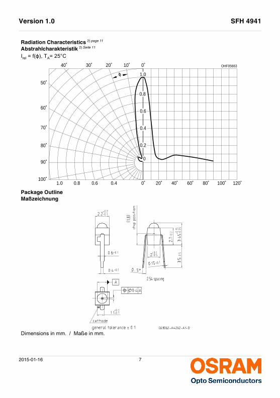
Radiation Characteristics 2) page 11
Abstrahlcharakteristik 2) Seite 11
Irel = f(ϕ), TA= 25°C
Package Outline
Maßzeichnung
Dimensions in mm. / Maße in mm.
OHF05663
0˚ 20˚ 40˚ 60˚ 80˚ 100˚ 120˚0.40.60.81.0100˚
90˚
80˚
70˚
60˚
50˚
0˚10˚20˚30˚40˚
0
0.2
0.4
0.6
0.8
1.0ϕ
2015-01-16 8
Version 1.0 SFH 4941
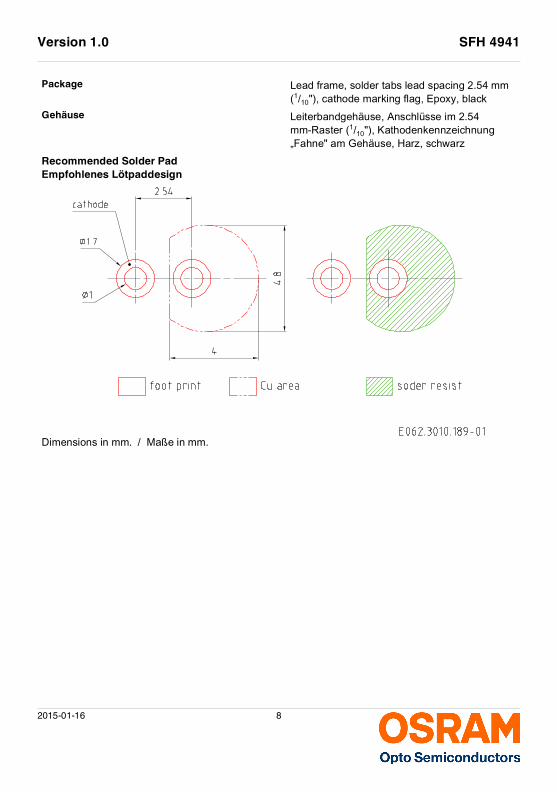
Package Lead frame, solder tabs lead spacing 2.54 mm (1/10"), cathode marking flag, Epoxy, black
Gehäuse Leiterbandgehäuse, Anschlüsse im 2.54 mm-Raster (1/10"), Kathodenkennzeichnung „Fahne" am Gehäuse, Harz, schwarz
Recommended Solder Pad
Empfohlenes Lötpaddesign
Dimensions in mm. / Maße in mm.
Version 1.0 SFH 4941
2015-01-16 9
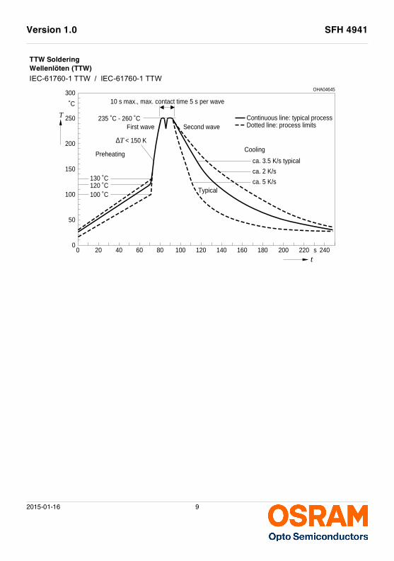
TTW Soldering
Wellenlöten (TTW)
IEC-61760-1 TTW / IEC-61760-1 TTW
00
s
OHA04645
50
100
150
200
250
300
t
T
˚C
235 ˚C - 260 ˚CFirst wave
20 40 60 80 100 120 140 160 180 200 220 240
Second wave
10 s max., max. contact time 5 s per wave
Preheating
T∆
100 ˚C120 ˚C130 ˚C
Typical
Cooling
ca. 3.5 K/s typical
ca. 2 K/s
ca. 5 K/s
Continuous line: typical processDotted line: process limits
< 150 K
2015-01-16 10
Version 1.0 SFH 4941
Disclaimer Disclaimer
Attention please!The information describes the type of component and shall not be considered as assured characteristics.Terms of delivery and rights to change design reserved. Due to technical requirements components may contain dangerous substances. For information on the types in question please contact our Sales Organization. If printed or downloaded, please find the latest version in the Internet.PackingPlease use the recycling operators known to you. We can also help you – get in touch with your nearest sales office. By agreement we will take packing material back, if it is sorted. You must bear the costs of transport. For packing material that is returned to us unsorted or which we are not obliged to accept, we shall have to invoice you for any costs incurred.Components used in life-support devices or systems must be expressly authorized for such purpose!Critical components* may only be used in life-support devices** or systems with the express written approval of OSRAM OS.
*) A critical component is a component used in a life-support device or system whose failure can reasonably be expected to cause the failure of that life-support device or system, or to affect its safety or the effectiveness of that device or system.**) Life support devices or systems are intended (a) to be implanted in the human body, or (b) to support and/or maintain and sustain human life. If they fail, it is reasonable to assume that the health and the life of the user may be endangered.
Bitte beachten!Lieferbedingungen und Änderungen im Design vorbehalten. Aufgrund technischer Anforderungen können die Bauteile Gefahrstoffe enthalten. Für weitere Informationen zu gewünschten Bauteilen, wenden Sie sich bitte an unseren Vertrieb. Falls Sie dieses Datenblatt ausgedruckt oder heruntergeladen haben, finden Sie die aktuellste Version im Internet.VerpackungBenutzen Sie bitte die Ihnen bekannten Recyclingwege. Wenn diese nicht bekannt sein sollten, wenden Sie sich bitte an das nächstgelegene Vertriebsbüro. Wir nehmen das Verpackungsmaterial zurück, falls dies vereinbart wurde und das Material sortiert ist. Sie tragen die Transportkosten. Für Verpackungsmaterial, das unsortiert an uns zurückgeschickt wird oder das wir nicht annehmen müssen, stellen wir Ihnen die anfallenden Kosten in Rechnung.Bauteile, die in lebenserhaltenden Apparaten und Systemen eingesetzt werden, müssen für diese Zwecke ausdrücklich zugelassen sein!Kritische Bauteile* dürfen in lebenserhaltenden Apparaten und Systemen** nur dann eingesetzt werden, wenn ein schriftliches Einverständnis von OSRAM OS vorliegt.
*) Ein kritisches Bauteil ist ein Bauteil, das in lebenserhaltenden Apparaten oder Systemen eingesetzt wird und dessen Defekt voraussichtlich zu einer Fehlfunktion dieses lebenserhaltenden Apparates oder Systems führen wird oder die Sicherheit oder Effektivität dieses Apparates oder Systems beeinträchtigt.**) Lebenserhaltende Apparate oder Systeme sind für (a) die Implantierung in den menschlichen Körper oder (b) für die Lebenserhaltung bestimmt. Falls Sie versagen, kann davon ausgegangen werden, dass die Gesundheit und das Leben des Patienten in Gefahr ist.
Version 1.0 SFH 4941
2015-01-16 11
Glossary Glossar
1) Thermal resistance: junction -ambient, mounted on PC-board (FR4), padsize 16 mm2 each
1) Wärmewiderstand: Sperrschicht -Umgebung, bei Montage auf FR4 Platine, Padgröße je 16 mm2
2) Typical Values: Due to the special conditions of the manufacturing processes of LED, the typical data or calculated correlations of technical parameters can only reflect statistical figures. These do not necessarily correspond to the actual parameters of each single product, which could differ from the typical data and calculated correlations or the typical characteristic line. If requested, e.g. because of technical improvements, these typ. data will be changed without any further notice.
2) Typische Werte: Wegen der besonderen Prozessbedingungen bei der Herstellung von LED können typische oder abgeleitete technische Parameter nur aufgrund statistischer Werte wiedergegeben werden. Diese stimmen nicht notwendigerweise mit den Werten jedes einzelnen Produktes überein, dessen Werte sich von typischen und abgeleiteten Werten oder typischen Kennlinien unterscheiden können. Falls erforderlich, z.B. aufgrund technischer Verbesserungen, werden diese typischen Werte ohne weitere Ankündigung geändert.
Version 1.0 SFH 4941
2015-01-16 12
Published by OSRAM Opto Semiconductors GmbH Leibnizstraße 4, D-93055 Regensburg www.osram-os.com © All Rights Reserved.