Embed Size (px)
Citation preview
INH
ALT
SVER
ZEIC
HN
IS /
SU
MM
ARY
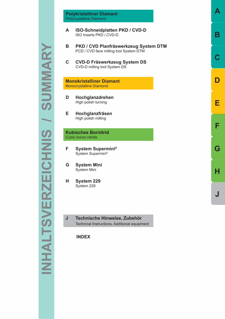
Polykristalliner DiamantPolycrystalline Diamond
Kubisches Bornitrid Cubic boron nitride
A ISO-Schneidplatten PKD / CVD-D ISO Inserts PKD / CVD-D
B PKD / CVD Planfräswerkzeug System DTM PCD / CVD face milling tool System DTM
Monokristalliner DiamantMonocrystalline Diamond
D Hochglanzdrehen High polish turning
E Hochglanzfräsen High polish milling
F System Supermini® System Supermini©
G System Mini System Mini
H System 229 System 229
J Technische Hinweise, Zubehör Technical Instructions, Additional equipment
INDEX
C CVD-D Fräswerkzeug System DS CVD-D milling tool System DS
E
A
B
C
D
F
G
H
J
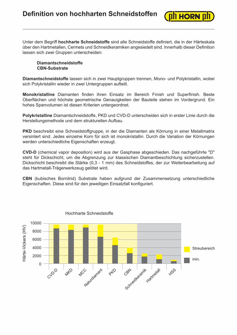
Definition von hochharten Schneidstoffen
Unter dem Begriff hochharte Schneidstoffe sind alle Schneidstoffe definiert, die in der Härteskala über den Hartmetallen, Cermets und Schneidkeramiken angesiedelt sind. Innerhalb dieser Definition lassen sich zwei Gruppen unterscheiden:
Diamantschneidstoffe CBN-Substrate
Diamantschneidstoffe lassen sich in zwei Hauptgruppen trennen, Mono- und Polykristallin, wobei sich Polykristallin wieder in zwei Untergruppen aufteilt.
Monokristalline Diamanten finden ihren Einsatz im Bereich Finish und Superfinish. Beste Oberflächen und höchste geometrische Genauigkeiten der Bauteile stehen im Vordergrund. Ein hohes Spanvolumen ist diesen Kriterien untergeordnet.
Polykristalline Diamantschneidstoffe, PKD und CVD-D unterscheiden sich in erster Linie durch die Herstellungsmethode und dem strukturellen Aufbau.
PKD beschreibt eine Schneidstoffgruppe, in der die Diamanten als Körnung in einer Metallmatrix versintert sind. Jedes einzelne Korn für sich ist monokristallin. Durch die Variation der Körnungen werden unterschiedliche Eigenschaften erzeugt.
CVD-D (chemical vapor deposition) wird aus der Gasphase abgeschieden. Das nachgeführte "D" steht für Dickschicht, um die Abgrenzung zur klassischen Diamantbeschichtung sicherzustellen. Dickschicht beschreibt die Stärke (0,3 - 1 mm) des Schneidstoffes, der zur Weiterbearbeitung auf das Hartmetall-Trägerwerkzeug gelötet wird.
CBN (kubisches Bornitrid) Substrate haben aufgrund der Zusammensetzung unterschiedliche Eigenschaften. Diese sind für den jeweiligen Einsatzfall konfiguriert.
10000
8000
6000
4000
2000
0
Här
te-V
icke
rs (H
V)
CVD-DMKD
MCC
Naturdi
aman
tPKD
CBN
Schne
idkera
mik
Hartmeta
llHSS
Streubereich
min.
Hochharte Schneidstoffe
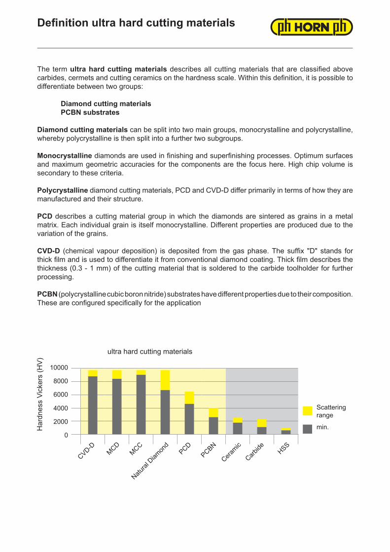
Definition ultra hard cutting materials
The term ultra hard cutting materials describes all cutting materials that are classified above carbides, cermets and cutting ceramics on the hardness scale. Within this definition, it is possible to differentiate between two groups:
Diamond cutting materials PCBN substrates
Diamond cutting materials can be split into two main groups, monocrystalline and polycrystalline, whereby polycrystalline is then split into a further two subgroups.
Monocrystalline diamonds are used in finishing and superfinishing processes. Optimum surfaces and maximum geometric accuracies for the components are the focus here. High chip volume is secondary to these criteria.
Polycrystalline diamond cutting materials, PCD and CVD-D differ primarily in terms of how they are manufactured and their structure.
PCD describes a cutting material group in which the diamonds are sintered as grains in a metal matrix. Each individual grain is itself monocrystalline. Different properties are produced due to the variation of the grains.
CVD-D (chemical vapour deposition) is deposited from the gas phase. The suffix "D" stands for thick film and is used to differentiate it from conventional diamond coating. Thick film describes the thickness (0.3 - 1 mm) of the cutting material that is soldered to the carbide toolholder for further processing.
PCBN (polycrystalline cubic boron nitride) substrates have different properties due to their composition. These are configured specifically for the application
10000
8000
6000
4000
2000
0
Har
dnes
s Vi
cker
s (H
V)
CVD-DMCD
MCC
Natural
Diam
ond
PCDPCBN
Ceramic
Carbide HSS
Scattering range
min.
ultra hard cutting materials

Anwendung hochharter SchneidstoffeApplication of ultra hard cutting materials
Die richtige Anwendung ist entscheidend, um das große Potential der CBN- und Diamantschneidstoffe in der Fertigung optimal zu nutzen.
Die große Härte des Diamanten in seinen unterschiedlich angebotenen Formen wie PKD, MKD, CVD-D oder Naturdiamant und der daraus resultierenden Schneidenschärfe verlangen ein teilweise anderes Herangehen an die jeweilige Zerspanungsaufgabe, als mit herkömmlichen Schneidstoffen.
Die hohe Warmbeständigkeit in Verbindung mit der hohen Härte, die zweithöchste nach Diamant, macht CBN (polykristallines kubisches Bornitrid) zum idealen Schneidstoff für die Bearbeitung von gehärteten Stählen. Die unterschiedlichen CBN-Substrate variieren in Zusammensetzung und der daraus resultierenden mechanisch-chemischen Eigenschaften. Neben der Zerspanung von gehärteten Stählen (45-70 HRC) eignet sich diese Schneidstoffgruppe auch hervorragend zur Bearbeitung von Gusswerkstoffen und Sonderlegierungen, bei denen Hartmetall und Schneidkeramik an ihre Grenzen kommen.
Die verschiedenen hochharten Schneidstoffe sind entsprechend Ihrer Zusammensetzung bzw. ihrem Aufbau für unterschiedliche Aufgaben optimiert. Daher ist die richtige Sortenwahl in Kombination mit der passenden Schneidengeometrie von größter Bedeutung.
Die empfohlenen Schnittparameter sind die Eckdaten, innerhalb derer ein wirtschaftliches Ergebnis und/oder Spanbruch erziehlt werden kann. In jedem Fall ist eine Anpassung der Parameter an die gesamte Zerspansituation vorzunehmen.
Um bestmögliche Ergebnisse zu erzielen, muss das gesamte Maschinenumfeld beachtet und auf ein möglichst hohes Stabilitätsniveau gebracht werden. Der Aufbau der Maschine, Führungen, Spindeln und die Spannsysteme für Werkstück und Werkzeuge haben einen entscheidenden Einfluss auf das Ergebnis.
Choosing the right application is crucial when it comes to maximising the huge potential of PCBN and diamond cutting materials in manufacturing.
The high level of hardness of diamond in its various forms such as PCD, MCD, CVD-D or natural diamond and the resulting cutting edge sharpness may mean that a different approach to the one taken with conventional cutting materials may be required depending on the machining task in question.
Its high heat resistance combined with the high level of hardness, which is second only to diamond, makes PCBN (polycrystalline cubic boron nitride) the ideal cutting material for machining hardened steels. The different PCBN substrates vary in terms of their composition and the resulting mechanical and chemical properties. In addition to the machining of hardened steels (45-70 HRC), this cutting material group is also highly suited to the machining of cast materials and special alloys – an application where carbides and cutting ceramics often reach their limits.
The composition and/or structure of the various ultra-hard cutting materials are optimised for different tasks. Therefore, it is extremely important that the right type of cutting material in combination with the right cutting geometry is selected.
The recommended cutting parameters are the key data that enable an efficient result and/or chip break to be achieved. In each case, it is necessary to adapt the parameters to the machining situation as a whole.
In order to achieve the best results possible, the entire machine environment must be taken into account and brought to the highest level of stability possible. The structure of the machine, guides, spindles and the clamping systems for the workpiece and tools play a key role with respect to the result.
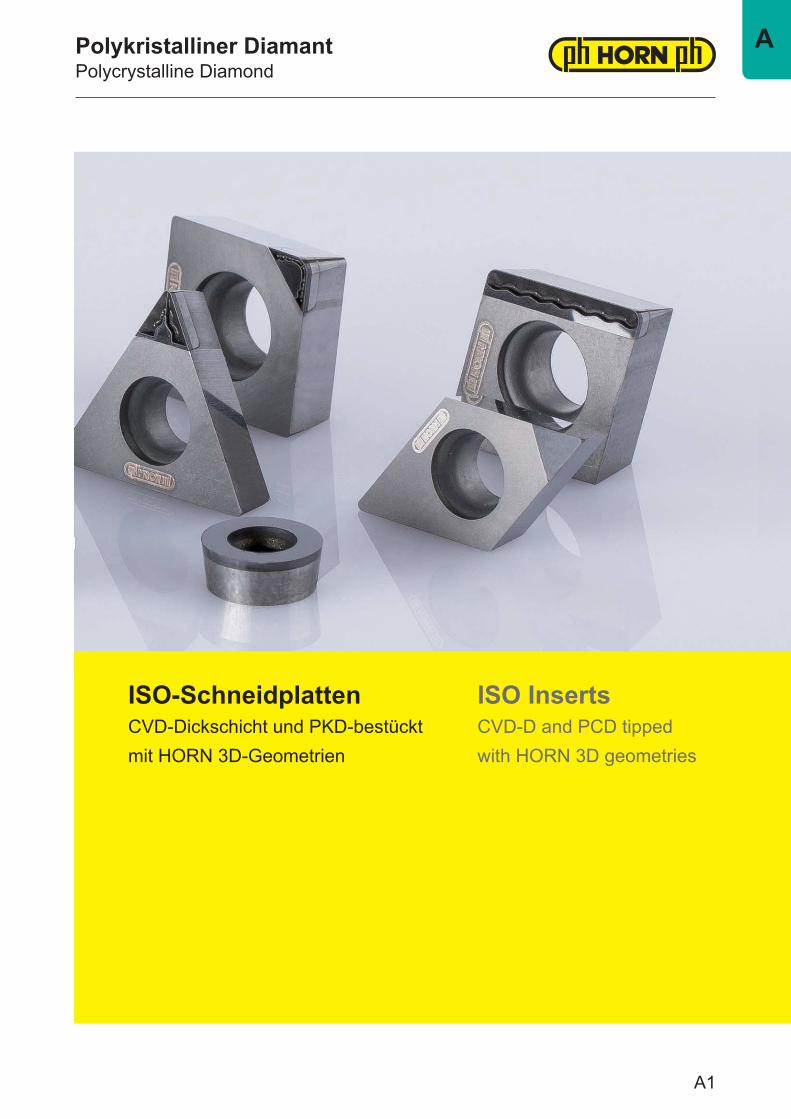
Polykristalliner DiamantPolycrystalline Diamond
ISO-SchneidplattenCVD-Dickschicht und PKD-bestücktmit HORN 3D-Geometrien
ISO InsertsCVD-D and PCD tippedwith HORN 3D geometries
A1
A
Die Verschleißfestigkeit von CVD-D übertrifft die von PKD deutlich. Grund hierfür ist die nicht vorhandene, metallische Bindefase und der daraus resultierende Diamantanteil von nahezu 100 Prozent. Einzelne, monokristalline Diamantkörner werden aus Gas abgeschieden und verwachsen untrennbar miteinander zu einer soliden, polymeren Diamantschicht.
Das Verfahren ähnelt der Diamantbeschichtung von Hartmetallwerkzeugen, jedoch ist dort die Schichtstärke nur wenige μm dick und somit nach relativ kurzer Einsatzdauer abgetragen.
Neben der maximalen Härte kommen noch andere, positive Eigenschaften von Diamant dem Zerspanungsprozess zugute. Die besondere Wärmeleitfähigkeit sorgt für einen kühlen Schnitt. Der geringe Reibungskoeffizient und eine geringe Adhäsionsneigung verhindert zuverlässig eine Aufbauschneidenbildung. Selbst bei kritischen Aluminiumknetlegierungen kann ohne Einsatz von Kühlschmierstoff, prozesssicher zerspant werden.
Lasertechnologie ist bei der Fertigung von CVD-D bestückten Schneiden unverzichtbar. Die hohe Schneidenqualität und das Einbringen von Spanformgeometrien wären ohne diese Technologie schlichtweg nicht möglich. Die erreichbaren Oberflächengüten sind grundsätzlich besser als die der von PKD erzeugten Schneiden. Lediglich die physikalisch bedingte, geringere Bruchzähigkeit schränkt den Einsatz etwas ein. Grundsätzlich ist der erreichbare Standweg, je nach Anwendung, der doppelte bis mehrfache vom Stand der PKD.
CVD-D, das Maximum an Härte
The wear resistance of CVD-D significantly exceeds that of PCD. The reason for this is that it does not have a metallic binding chamfer and the fact that it has a resulting diamond component of almost 100 per cent. Individual, monocrystalline diamond grains are deposited from gas and grow together so that they cannot be separated to form a solid, polymeric diamond layer.
The process is similar to the diamond coating of carbide tools but the layer thickness is just a few μm thick and is therefore worn away after a relatively short time in use.
In addition to maximum hardness, other positive properties of diamond also benefit the machining process. Its special heat conductivity ensures cool cutting. The low coefficient of friction and a low adhesive tendency re-liably prevent build-up edges from forming. Reliable machining processes can be performed even with critical aluminium wrought alloys without using cooling lubricant.
Laser technology is indispensable when it comes to manufacturing CVD-D cutting edges. It would simply be impossible to achieve the high cutting quality and apply chip shape geometries without this technology. The surface qualities that can be achieved are significantly better than those of cutting edges produced from PCD. Only its lower fracture toughness, which is due to its physical properties, limits the use of the material to some extent.The achievable tool life is double or several times that of tools manufactured from PCD.
CVD-D, maximum strength
A2
A
PKD ist ein Verbundschneidstoff. Diamantkörner, jedes für sich monokristallin, sind in einer Metallmatrix, in der Regel Kobalt, miteinander versintert. Innerhalb des Sinterprozesses kommt es zu einem interkristallinen Kornwachstum, bei dem im begrenzten Umfang, die einzelnen Körner miteinander verwachsen und somit die Verschleißeigenschaften im späteren Einsatz positiv beeinflussen.
Die Größe und Qualität der verwendeten Körner sind neben der Sintertechnologie Index für die Verschleißfestigkeit. Daraus leitet sich der theoretische Grundsatz ab „je größer das Korn, desto besser der Abrasionswiederstand". Jedoch leidet dadurch die erreichbare Schneidkantenqualität, Schartigkeit und Schärfe, unabhängig der zur Schneid-kantenherstellung verwendeten Fertigungstechnologie. Auch der prozentuale Volumenanteil der metallischen Bindephase steigt und wirkt sich negativ aus.
Das HORN-Hochleistung-PKD setzt sich aus einer ausgefeilten Mixtur unterschiedlicher Größen von Diamantkörnern zusammen. Der Volumenanteil von Diamant steigt, Wirkhärte, Zähigkeit und Schneidenqualität ebenso. Strenge Qualitätsstandards und deren Kontrolle sind selbstverständlich und sorgen für maximale Leistung.
PKD ist nicht gleich PKD
PCD is a compound cutting material. Diamond grains, each one of a monocrystalline nature, are sintered to each other in a metal matrix, generally cobalt. During the sintering process, the grains grow within the crystals and the individual grains grow together to a limited extent, thereby affecting the wear properties during subse-quent use.
In addition to the sintering technology, the size and quality of the grains used are an indicator of wear resi-stance. It is possible to derive the following theoretical principle: "the larger the grain, the better the abrasion resistance". However, this compromises the cutting edge quality, chipping and sharpness that can be achie-ved, irrespective of the manufacturing technology used to produce the cutting edges. The percentage volume fraction of the metallic binding phase also increases and has a negative effect.
HORN high-performance PCD is comprised of a sophisticated mixture of different diamond grain sizes. The volume fraction of diamond increases, as do effective hardness, toughness and cutting quality. It goes without saying that strict quality standards are observed and monitored and ensure maximum performance.
Not all PCD is the same
A3
A
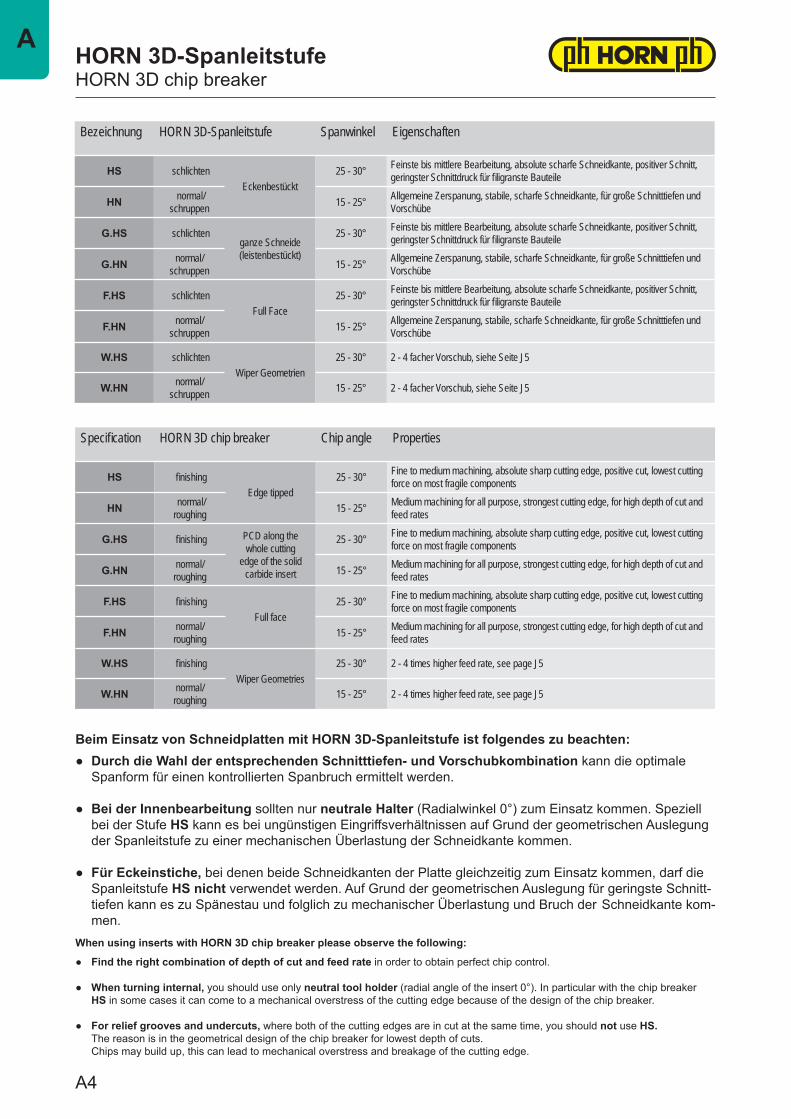
Bezeichnung HORN 3D-Spanleitstufe Spanwinkel Eigenschaften
HS schlichtenEckenbestückt
25 - 30° Feinste bis mittlere Bearbeitung, absolute scharfe Schneidkante, positiver Schnitt, geringster Schnittdruck für filigranste Bauteile
HN normal/schruppen 15 - 25° Allgemeine Zerspanung, stabile, scharfe Schneidkante, für große Schnitttiefen und
Vorschübe
G.HS schlichtenganze Schneide(leistenbestückt)
25 - 30° Feinste bis mittlere Bearbeitung, absolute scharfe Schneidkante, positiver Schnitt, geringster Schnittdruck für filigranste Bauteile
G.HN normal/schruppen 15 - 25° Allgemeine Zerspanung, stabile, scharfe Schneidkante, für große Schnitttiefen und
Vorschübe
F.HS schlichtenFull Face
25 - 30° Feinste bis mittlere Bearbeitung, absolute scharfe Schneidkante, positiver Schnitt, geringster Schnittdruck für filigranste Bauteile
F.HN normal/schruppen 15 - 25° Allgemeine Zerspanung, stabile, scharfe Schneidkante, für große Schnitttiefen und
Vorschübe
W.HS schlichtenWiper Geometrien
25 - 30° 2 - 4 facher Vorschub, siehe Seite J5
W.HN normal/schruppen 15 - 25° 2 - 4 facher Vorschub, siehe Seite J5
Specification HORN 3D chip breaker Chip angle Properties
HS finishingEdge tipped
25 - 30° Fine to medium machining, absolute sharp cutting edge, positive cut, lowest cutting force on most fragile components
HN normal/roughing 15 - 25° Medium machining for all purpose, strongest cutting edge, for high depth of cut and
feed rates
G.HS finishing PCD along thewhole cutting
edge of the solidcarbide insert
25 - 30° Fine to medium machining, absolute sharp cutting edge, positive cut, lowest cutting force on most fragile components
G.HN normal/roughing 15 - 25° Medium machining for all purpose, strongest cutting edge, for high depth of cut and
feed rates
F.HS finishingFull face
25 - 30° Fine to medium machining, absolute sharp cutting edge, positive cut, lowest cutting force on most fragile components
F.HN normal/roughing 15 - 25° Medium machining for all purpose, strongest cutting edge, for high depth of cut and
feed rates
W.HS finishingWiper Geometries
25 - 30° 2 - 4 times higher feed rate, see page J5
W.HN normal/roughing 15 - 25° 2 - 4 times higher feed rate, see page J5
HORN 3D-SpanleitstufeHORN 3D chip breaker
Beim Einsatz von Schneidplatten mit HORN 3D-Spanleitstufe ist folgendes zu beachten:
When using inserts with HORN 3D chip breaker please observe the following:
● Durch die Wahl der entsprechenden Schnitttiefen- und Vorschubkombination kann die optimale Spanform für einen kontrollierten Spanbruch ermittelt werden.
● Bei der Innenbearbeitung sollten nur neutrale Halter (Radialwinkel 0°) zum Einsatz kommen. Speziell bei der Stufe HS kann es bei ungünstigen Eingriffsverhältnissen auf Grund der geometrischen Auslegung der Spanleitstufe zu einer mechanischen Überlastung der Schneidkante kommen.
● Für Eckeinstiche, bei denen beide Schneidkanten der Platte gleichzeitig zum Einsatz kommen, darf die Spanleitstufe HS nicht verwendet werden. Auf Grund der geometrischen Auslegung für geringste Schnitt- tiefen kann es zu Spänestau und folglich zu mechanischer Überlastung und Bruch der Schneidkante kom- men.
● Find the right combination of depth of cut and feed rate in order to obtain perfect chip control.
● When turning internal, you should use only neutral tool holder (radial angle of the insert 0°). In particular with the chip breaker HS in some cases it can come to a mechanical overstress of the cutting edge because of the design of the chip breaker.
● For relief grooves and undercuts, where both of the cutting edges are in cut at the same time, you should not use HS. The reason is in the geometrical design of the chip breaker for lowest depth of cuts. Chips may build up, this can lead to mechanical overstress and breakage of the cutting edge.
A4
A
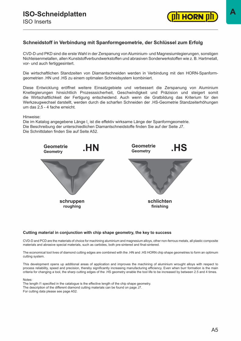
Schneidstoff in Verbindung mit Spanformgeometrie, der Schlüssel zum Erfolg
CVD-D und PKD sind die erste Wahl in der Zerspanung von Aluminium- und Magnesiumlegierungen, sonstigen Nichteisenmetallen, allen Kunststoffverbundwerkstoffen und abrasiven Sonderwerkstoffen wie z. B. Hartmetall, vor- und auch fertiggesintert.
Die wirtschaftlichen Standzeiten von Diamantschneiden werden in Verbindung mit den HORN-Spanform-geometrien .HN und .HS zu einem optimalen Schneidsystem kombiniert.
Diese Entwicklung eröffnet weitere Einsatzgebiete und verbessert die Zerspanung von Aluminium Knetlegierungen hinsichtlich Prozesssicherheit, Geschwindigkeit und Präzision und steigert somit die Wirtschaftlichkeit der Fertigung entscheidend. Auch wenn die Gratbildung das Kriterium für den Werkzeugwechsel darstellt, werden durch die scharfen Schneiden der .HS-Geometrie Standzeiterhöhungen um das 2,5 - 4 fache erreicht.
Hinweise:Die im Katalog angegebene Länge l1 ist die effektiv wirksame Länge der Spanformgeometrie. Die Beschreibung der unterschiedlichen Diamantschneidstoffe finden Sie auf der Seite J7.Die Schnittdaten finden Sie auf Seite A52.
.HN .HS
Cutting material in conjunction with chip shape geometry, the key to success
CVD-D and PCD are the materials of choice for machining aluminium and magnesium alloys, other non-ferrous metals, all plastic composite materials and abrasive special materials, such as carbides, both pre-sintered and final-sintered.
The economical tool lives of diamond cutting edges are combined with the .HN and .HS HORN chip shape geometries to form an optimum cutting system.
This development opens up additional areas of application and improves the machining of aluminium wrought alloys with respect to process reliability, speed and precision, thereby significantly increasing manufacturing efficiency. Even when burr formation is the main criteria for changing a tool, the sharp cutting edges of the .HS geometry enable the tool life to be increased by between 2.5 and 4 times.
Notes:The length l1 specified in the catalogue is the effective length of the chip shape geometry.The description of the different diamond cutting materials can be found on page J7. For cutting data please see page A52.
GeometrieGeometry
GeometrieGeometry
schruppenroughing
schlichtenfinishing
ISO-SchneidplattenISO Inserts
A5
A
21 3 4 5
1 2 4
3 5
m s d*A ±0,005 ±0,025 ±0,025E ±0,025 ±0,025 ±0,025F ±0,005 ±0,025 ±0,013G ±0,025 ±0,013 ±0,025H ±0,013 ±0,025 ±0,013J ±0,005 ±0,025 ±0,05-0,15K ±0,013 ±0,025 ±0,05-0,15L ±0,025 ±0,025 ±0,05-0,15M ±0,08-0,20 ±0,05-0,13 ±0,05-0,15N ±0,08-0,20 ±0,025 ±0,05-0,15U ±0,13-0,38 ±0,13 ±0,08-0,25
A
G
M
N
P
R
T
W
X SonderSpecial
s
dmd d
m m
dd
mm
T
S
R
L
A,B,K
C,D,E M,V
H O P
W
RH120°
l l l d
l l l
ll l
IC
O135°
P108°
C80°
D55°
E75°
L90°
A85°
B82°
K55°
S90°
T60°
W80°
M86°
V35°
A
C
E
G
P
3°
7°
20°
30°
11°
B
D
F
N
5°
15°
25°
0°
ISO-SchneidplattenISO Inserts
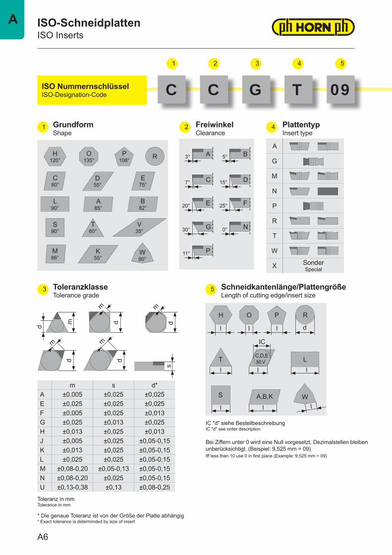
C C G T 09ISO NummernschlüsselISO-Designation-Code
GrundformShape
FreiwinkelClearance
PlattentypInsert type
ToleranzklasseTolerance grade
Schneidkantenlänge/PlattengrößeLength of cutting edge/insert size
Toleranz in mmTolerance in mm
* Die genaue Toleranz ist von der Größe der Platte abhängig* Exact tolerance is determinded by size of insert
IC "d" siehe BestellbeschreibungIC "d" see order description
Bei Ziffern unter 0 wird eine Null vorgesetzt, Dezimalstellen bleiben unberücksichtigt. (Beispiel: 9,525 mm = 09)Iff less than 10 use 0 in fi rst place (Example: 9,525 mm = 09)
A6
A
76 8 9 10 11
6 7 8
9 10
11
s01 1,59T1 1,9802 2,3803 3,18T3 3,9704 4,7605 5,5606 6,35
RadiusRadius
00 Scharfe EckeSharp corner
01 0,1 mm02 0,2 mm04 0,4 mm08 0,8 mm12 1,2 mm16 1,6 mm
00 Runde SP (inch)Round insert (inch)
M0 Runde SP (metr.)Round insert (metr.)
ohnewithout
EckenbestücktEdge tipped
F Full FaceFull face
G Ganze Schneide Whole cutting edge
W Wiper GeometrienWiper Geometries
MD10 MKD / MCD
HD08 CVD-D / CVD-D
PD70 PKD / PCD
PD75 PKD / PCD
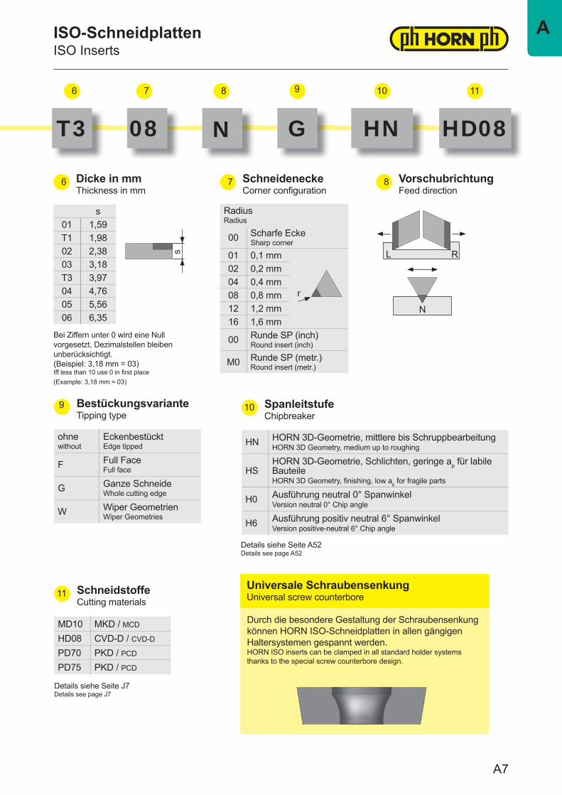
HN HORN 3D-Geometrie, mittlere bis SchruppbearbeitungHORN 3D Geometry, medium up to roughing
HSHORN 3D-Geometrie, Schlichten, geringe ap für labile BauteileHORN 3D Geometry, fi nishing, low ap for fragile parts
H0 Ausführung neutral 0° SpanwinkelVersion neutral 0° Chip angle
H6 Ausführung positiv neutral 6° SpanwinkelVersion positive-neutral 6° Chip angle
s
r
N
RL
ISO-SchneidplattenISO Inserts
T3 08 N G HN HD08
Dicke in mmThickness in mm
Bei Ziffern unter 0 wird eine Null vorgesetzt, Dezimalstellen bleiben unberücksichtigt.(Beispiel: 3,18 mm = 03)Iff less than 10 use 0 in fi rst place(Example: 3,18 mm = 03)
SchneideneckeCorner confi guration
VorschubrichtungFeed direction
BestückungsvarianteTipping type
SpanleitstufeChipbreaker
SchneidstoffeCutting materials
Details siehe Seite J7Details see page J7
Universale SchraubensenkungUniversal screw counterbore
Durch die besondere Gestaltung der Schraubensenkung können HORN ISO-Schneidplatten in allen gängigen Haltersystemen gespannt werden.HORN ISO inserts can be clamped in all standard holder systems thanks to the special screw counterbore design.
Details siehe Seite A52Details see page A52
A7
A
Abmessungen in mmDimensions in mm
Schneiden nur optisch vermessen!Cutting edges must be measured optically!
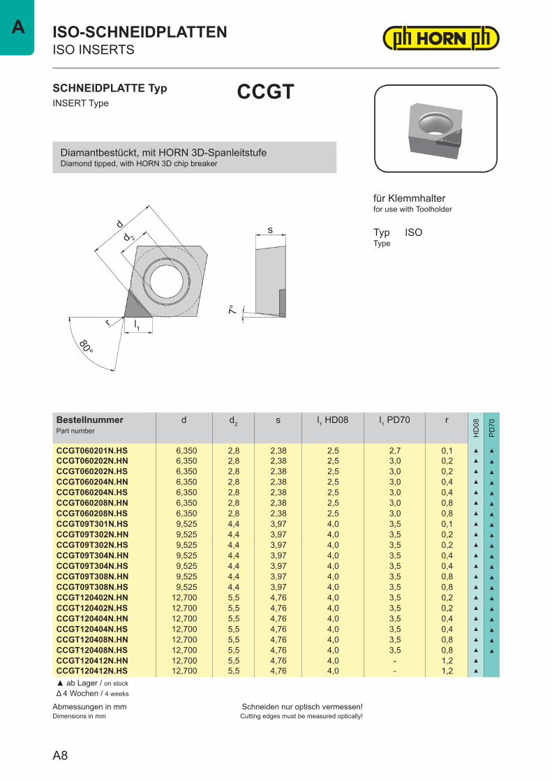
BestellnummerPart number
d d2 s l1 HD08 l1 PD70 r
HD
08
PD
70
CCGT060201N.HS 6,350 2,8 2,38 2,5 2,7 0,1 ▲ ▲
CCGT060202N.HN 6,350 2,8 2,38 2,5 3,0 0,2 ▲ ▲
CCGT060202N.HS 6,350 2,8 2,38 2,5 3,0 0,2 ▲ ▲
CCGT060204N.HN 6,350 2,8 2,38 2,5 3,0 0,4 ▲ ▲
CCGT060204N.HS 6,350 2,8 2,38 2,5 3,0 0,4 ▲ ▲
CCGT060208N.HN 6,350 2,8 2,38 2,5 3,0 0,8 ▲ ▲
CCGT060208N.HS 6,350 2,8 2,38 2,5 3,0 0,8 ▲ ▲
CCGT09T301N.HS 9,525 4,4 3,97 4,0 3,5 0,1 ▲ ▲
CCGT09T302N.HN 9,525 4,4 3,97 4,0 3,5 0,2 ▲ ▲
CCGT09T302N.HS 9,525 4,4 3,97 4,0 3,5 0,2 ▲ ▲
CCGT09T304N.HN 9,525 4,4 3,97 4,0 3,5 0,4 ▲ ▲
CCGT09T304N.HS 9,525 4,4 3,97 4,0 3,5 0,4 ▲ ▲
CCGT09T308N.HN 9,525 4,4 3,97 4,0 3,5 0,8 ▲ ▲
CCGT09T308N.HS 9,525 4,4 3,97 4,0 3,5 0,8 ▲ ▲
CCGT120402N.HN 12,700 5,5 4,76 4,0 3,5 0,2 ▲ ▲
CCGT120402N.HS 12,700 5,5 4,76 4,0 3,5 0,2 ▲ ▲
CCGT120404N.HN 12,700 5,5 4,76 4,0 3,5 0,4 ▲ ▲
CCGT120404N.HS 12,700 5,5 4,76 4,0 3,5 0,4 ▲ ▲
CCGT120408N.HN 12,700 5,5 4,76 4,0 3,5 0,8 ▲ ▲
CCGT120408N.HS 12,700 5,5 4,76 4,0 3,5 0,8 ▲ ▲
CCGT120412N.HN 12,700 5,5 4,76 4,0 - 1,2 ▲
CCGT120412N.HS 12,700 5,5 4,76 4,0 - 1,2 ▲
▲ ab Lager / on stockΔ 4 Wochen / 4 weeks
SCHNEIDPLATTE TypINSERT Type
CCGT
ISO-SCHNEIDPLATTENISO INSERTS
for use with Toolholder
TypType
ISO
für Klemmhalter
Diamantbestückt, mit HORN 3D-SpanleitstufeDiamond tipped, with HORN 3D chip breaker
A8
A

Abmessungen in mmDimensions in mm
Schneiden nur optisch vermessen!Cutting edges must be measured optically!
BestellnummerPart number
d d2 s l1 HD08 l1 PD70 r
HD
08
PD
70
CCGT060201N.H6 6,350 2,8 2,38 3,0 3,2 0,1 ▲ ▲
CCGT060202N.H6 6,350 2,8 2,38 3,0 3,5 0,2 ▲ ▲
CCGT060204N.H6 6,350 2,8 2,38 3,0 3,5 0,4 ▲ ▲
CCGT060208N.H6 6,350 2,8 2,38 3,0 3,5 0,8 ▲ ▲
CCGT09T301N.H6 9,525 4,4 3,97 4,5 - 0,1 ▲
CCGT09T302N.H6 9,525 4,4 3,97 4,5 4,0 0,2 ▲ ▲
CCGT09T304N.H6 9,525 4,4 3,97 4,5 4,0 0,4 ▲ ▲
CCGT09T308N.H6 9,525 4,4 3,97 4,5 4,0 0,8 ▲ ▲
CCGT09T312N.H6 9,525 4,4 3,97 4,5 - 1,2 ▲
CCGT120402N.H6 12,700 5,5 4,76 4,5 4,0 0,2 ▲ ▲
CCGT120404N.H6 12,700 5,5 4,76 4,5 4,0 0,4 ▲ ▲
CCGT120408N.H6 12,700 5,5 4,76 4,5 4,0 0,8 ▲ ▲
CCGT120412N.H6 12,700 5,5 4,76 4,5 - 1,2 ▲
▲ ab Lager / on stockΔ 4 Wochen / 4 weeks
SCHNEIDPLATTE TypINSERT Type
CCGT
ISO-SCHNEIDPLATTENISO INSERTS
for use with Toolholder
TypType
ISO
für Klemmhalter
Diamantbestückt, Ausführung "positiv-neutral"Diamond tipped, Version "positive-neutral"
A9
A
Abmessungen in mmDimensions in mm
Schneiden nur optisch vermessen!Cutting edges must be measured optically!
BestellnummerPart number
d d2 s l1 HD08 l1 PD70 r
HD
08
PD
70
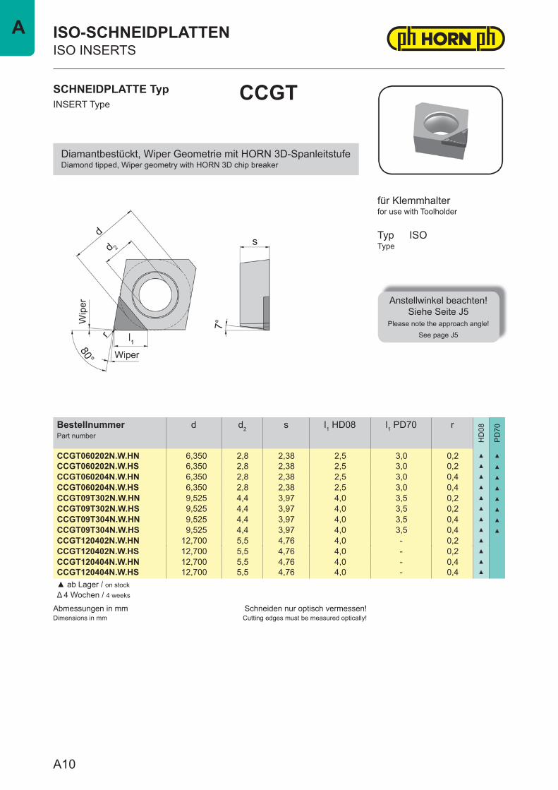
CCGT060202N.W.HN 6,350 2,8 2,38 2,5 3,0 0,2 ▲ ▲
CCGT060202N.W.HS 6,350 2,8 2,38 2,5 3,0 0,2 ▲ ▲
CCGT060204N.W.HN 6,350 2,8 2,38 2,5 3,0 0,4 ▲ ▲
CCGT060204N.W.HS 6,350 2,8 2,38 2,5 3,0 0,4 ▲ ▲
CCGT09T302N.W.HN 9,525 4,4 3,97 4,0 3,5 0,2 ▲ ▲
CCGT09T302N.W.HS 9,525 4,4 3,97 4,0 3,5 0,2 ▲ ▲
CCGT09T304N.W.HN 9,525 4,4 3,97 4,0 3,5 0,4 ▲ ▲
CCGT09T304N.W.HS 9,525 4,4 3,97 4,0 3,5 0,4 ▲ ▲
CCGT120402N.W.HN 12,700 5,5 4,76 4,0 - 0,2 ▲
CCGT120402N.W.HS 12,700 5,5 4,76 4,0 - 0,2 ▲
CCGT120404N.W.HN 12,700 5,5 4,76 4,0 - 0,4 ▲
CCGT120404N.W.HS 12,700 5,5 4,76 4,0 - 0,4 ▲
▲ ab Lager / on stockΔ 4 Wochen / 4 weeks
SCHNEIDPLATTE TypINSERT Type
CCGT
ISO-SCHNEIDPLATTENISO INSERTS
for use with Toolholder
TypType
ISO
für Klemmhalter
Diamantbestückt, Wiper Geometrie mit HORN 3D-SpanleitstufeDiamond tipped, Wiper geometry with HORN 3D chip breaker
Anstellwinkel beachten!Siehe Seite J5
Please note the approach angle!See page J5
A10
A

Abmessungen in mmDimensions in mm
Schneiden nur optisch vermessen!Cutting edges must be measured optically!
BestellnummerPart number
d d2 s l1 PD70 r
HD
08
PD
70
CCGT060201N.W.H6 6,350 2,8 2,38 3,0 0,1 ▲
CCGT060202N.W.H6 6,350 2,8 2,38 3,5 0,2 ▲
CCGT060204N.W.H6 6,350 2,8 2,38 3,5 0,4 ▲
CCGT09T301N.W.H6 9,525 4,4 3,97 3,7 0,1 ▲
CCGT09T302N.W.H6 9,525 4,4 3,97 4,0 0,2 ▲
CCGT09T304N.W.H6 9,525 4,4 3,97 4,0 0,4 ▲
CCGT120402N.W.H6 12,700 5,5 4,76 4,0 0,2 ▲
CCGT120404N.W.H6 12,700 5,5 4,76 4,0 0,4 ▲
▲ ab Lager / on stockΔ 4 Wochen / 4 weeks
SCHNEIDPLATTE TypINSERT Type
CCGT
ISO-SCHNEIDPLATTENISO INSERTS
for use with Toolholder
TypType
Anstellwinkel beachten!Siehe Seite J5
Please note the approach angle!See page J5
ISO
für Klemmhalter
Diamantbestückt, Wiper Geometrie, Ausführung "positiv-neutral"Diamond tipped, Wiper geometry, Version "positive-neutral"
A11
A
Abmessungen in mmDimensions in mm
Schneiden nur optisch vermessen!Cutting edges must be measured optically!
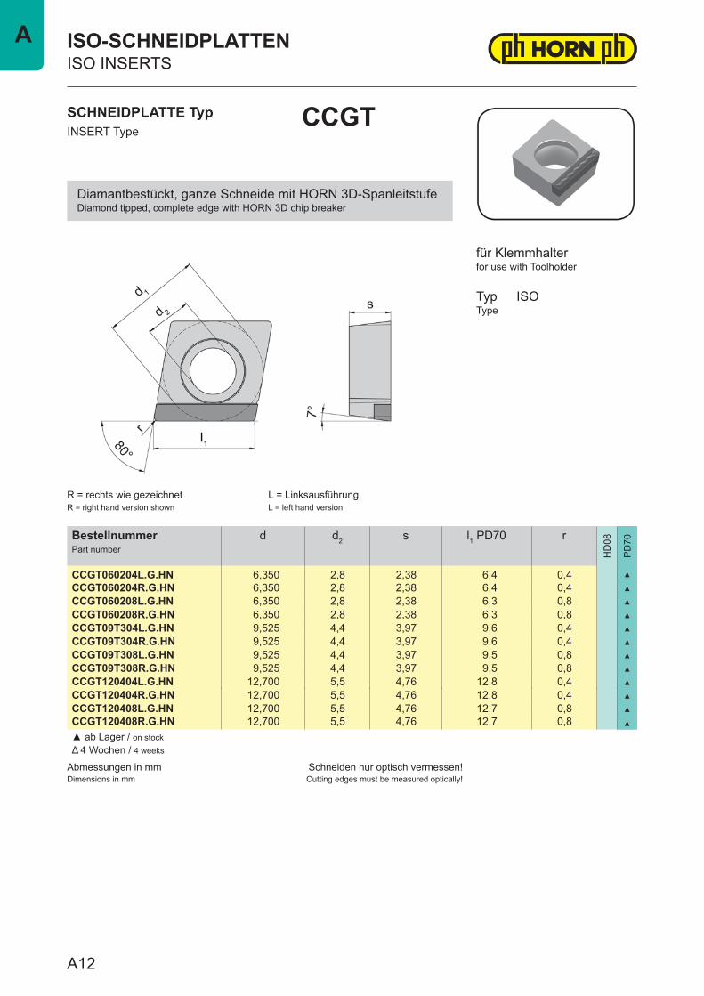
BestellnummerPart number
d d2 s l1 PD70 r
HD
08
PD
70
CCGT060204L.G.HN 6,350 2,8 2,38 6,4 0,4 ▲
CCGT060204R.G.HN 6,350 2,8 2,38 6,4 0,4 ▲
CCGT060208L.G.HN 6,350 2,8 2,38 6,3 0,8 ▲
CCGT060208R.G.HN 6,350 2,8 2,38 6,3 0,8 ▲
CCGT09T304L.G.HN 9,525 4,4 3,97 9,6 0,4 ▲
CCGT09T304R.G.HN 9,525 4,4 3,97 9,6 0,4 ▲
CCGT09T308L.G.HN 9,525 4,4 3,97 9,5 0,8 ▲
CCGT09T308R.G.HN 9,525 4,4 3,97 9,5 0,8 ▲
CCGT120404L.G.HN 12,700 5,5 4,76 12,8 0,4 ▲
CCGT120404R.G.HN 12,700 5,5 4,76 12,8 0,4 ▲
CCGT120408L.G.HN 12,700 5,5 4,76 12,7 0,8 ▲
CCGT120408R.G.HN 12,700 5,5 4,76 12,7 0,8 ▲
▲ ab Lager / on stockΔ 4 Wochen / 4 weeks
SCHNEIDPLATTE TypINSERT Type
CCGT
ISO-SCHNEIDPLATTENISO INSERTS
for use with Toolholder
TypType
ISO
R = rechts wie gezeichnetR = right hand version shown
L = LinksausführungL = left hand version
für Klemmhalter
Diamantbestückt, ganze Schneide mit HORN 3D-SpanleitstufeDiamond tipped, complete edge with HORN 3D chip breaker
A12
A
Abmessungen in mmDimensions in mm
Schneiden nur optisch vermessen!Cutting edges must be measured optically!
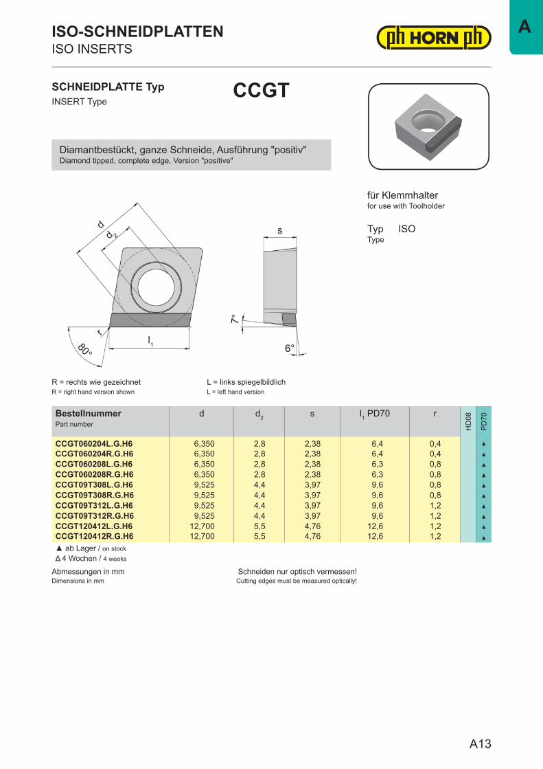
BestellnummerPart number
d d2 s l1 PD70 r
HD
08
PD
70
CCGT060204L.G.H6 6,350 2,8 2,38 6,4 0,4 ▲
CCGT060204R.G.H6 6,350 2,8 2,38 6,4 0,4 ▲
CCGT060208L.G.H6 6,350 2,8 2,38 6,3 0,8 ▲
CCGT060208R.G.H6 6,350 2,8 2,38 6,3 0,8 ▲
CCGT09T308L.G.H6 9,525 4,4 3,97 9,6 0,8 ▲
CCGT09T308R.G.H6 9,525 4,4 3,97 9,6 0,8 ▲
CCGT09T312L.G.H6 9,525 4,4 3,97 9,6 1,2 ▲
CCGT09T312R.G.H6 9,525 4,4 3,97 9,6 1,2 ▲
CCGT120412L.G.H6 12,700 5,5 4,76 12,6 1,2 ▲
CCGT120412R.G.H6 12,700 5,5 4,76 12,6 1,2 ▲
▲ ab Lager / on stockΔ 4 Wochen / 4 weeks
SCHNEIDPLATTE TypINSERT Type
CCGT
ISO-SCHNEIDPLATTENISO INSERTS
for use with Toolholder
TypType
ISO
R = rechts wie gezeichnetR = right hand version shown
L = links spiegelbildlichL = left hand version
für Klemmhalter
Diamantbestückt, ganze Schneide, Ausführung "positiv"Diamond tipped, complete edge, Version "positive"
A13
A
Abmessungen in mmDimensions in mm
Schneiden nur optisch vermessen!Cutting edges must be measured optically!
BestellnummerPart number
d d2 s l1 HD08 l1 PD70 r
HD
08
PD
70
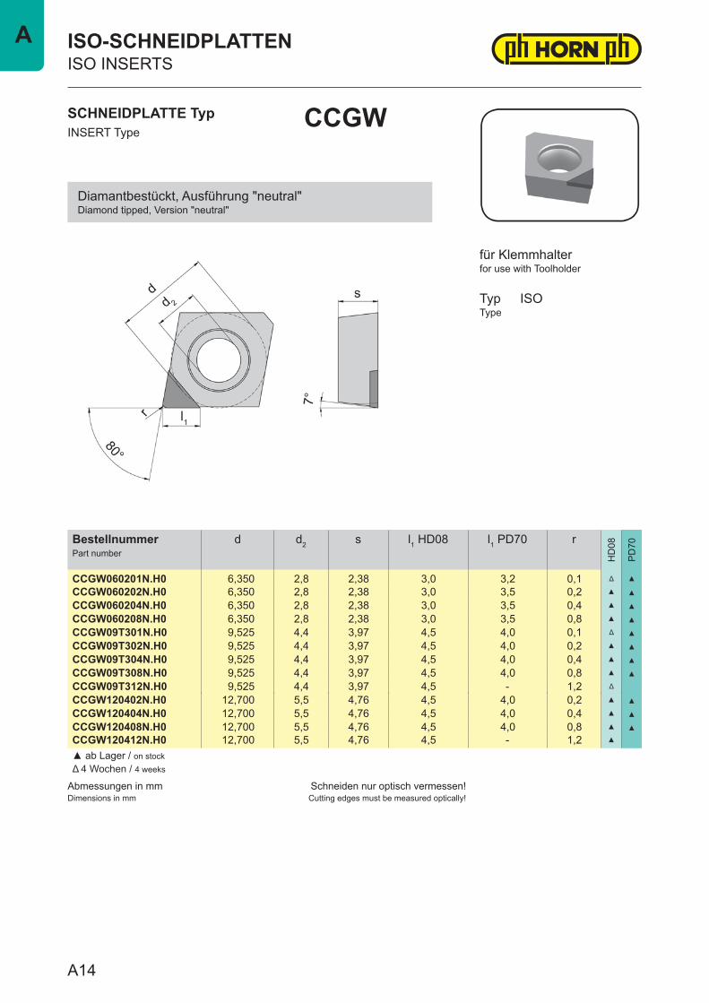
CCGW060201N.H0 6,350 2,8 2,38 3,0 3,2 0,1 Δ ▲
CCGW060202N.H0 6,350 2,8 2,38 3,0 3,5 0,2 ▲ ▲
CCGW060204N.H0 6,350 2,8 2,38 3,0 3,5 0,4 ▲ ▲
CCGW060208N.H0 6,350 2,8 2,38 3,0 3,5 0,8 ▲ ▲
CCGW09T301N.H0 9,525 4,4 3,97 4,5 4,0 0,1 Δ ▲
CCGW09T302N.H0 9,525 4,4 3,97 4,5 4,0 0,2 ▲ ▲
CCGW09T304N.H0 9,525 4,4 3,97 4,5 4,0 0,4 ▲ ▲
CCGW09T308N.H0 9,525 4,4 3,97 4,5 4,0 0,8 ▲ ▲
CCGW09T312N.H0 9,525 4,4 3,97 4,5 - 1,2 Δ
CCGW120402N.H0 12,700 5,5 4,76 4,5 4,0 0,2 ▲ ▲
CCGW120404N.H0 12,700 5,5 4,76 4,5 4,0 0,4 ▲ ▲
CCGW120408N.H0 12,700 5,5 4,76 4,5 4,0 0,8 ▲ ▲
CCGW120412N.H0 12,700 5,5 4,76 4,5 - 1,2 ▲
▲ ab Lager / on stockΔ 4 Wochen / 4 weeks
SCHNEIDPLATTE TypINSERT Type
CCGW
ISO-SCHNEIDPLATTENISO INSERTS
for use with Toolholder
TypType
ISO
für Klemmhalter
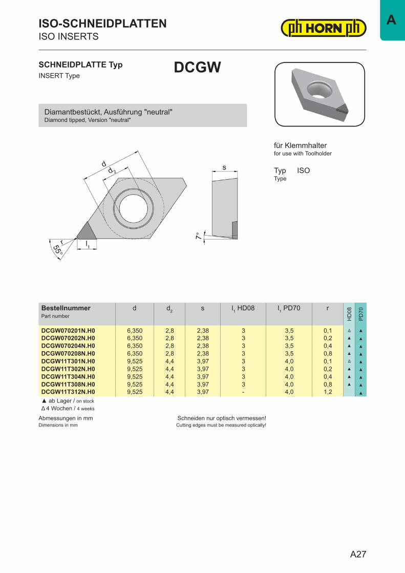
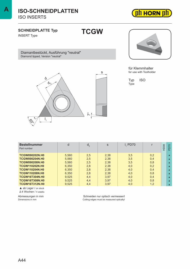
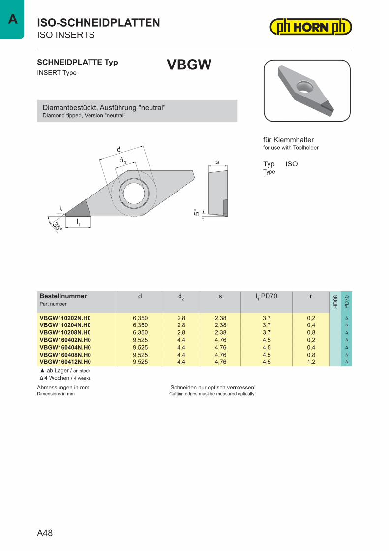
Diamantbestückt, Ausführung "neutral"Diamond tipped, Version "neutral"
A14
A

Abmessungen in mmDimensions in mm
Schneiden nur optisch vermessen!Cutting edges must be measured optically!
BestellnummerPart number
d d2 s l1 PD70 r
HD
08
PD
70
CCGW060201N.W.H0 6,350 2,8 2,38 3,2 0,1 ▲
CCGW060202N.W.H0 6,350 2,8 2,38 3,5 0,2 ▲
CCGW060204N.W.H0 6,350 2,8 2,38 3,5 0,4 ▲
CCGW09T301N.W.H0 9,525 4,4 3,97 3,7 0,1 ▲
CCGW09T302N.W.H0 9,525 4,4 3,97 4,0 0,2 ▲
CCGW09T304N.W.H0 9,525 4,4 3,97 4,0 0,4 ▲
CCGW120402N.W.H0 12,700 5,5 4,76 4,0 0,2 ▲
CCGW120404N.W.H0 12,700 5,5 4,76 4,0 0,4 ▲
▲ ab Lager / on stockΔ 4 Wochen / 4 weeks
SCHNEIDPLATTE TypINSERT Type
CCGW
ISO-SCHNEIDPLATTENISO INSERTS
for use with Toolholder
TypType
ISO
für Klemmhalter
Diamantbestückt, Wiper Geometrie, Ausführung "neutral"Diamond tipped, Wiper geometry, Version "neutral"
Anstellwinkel beachten!Siehe Seite J5
Please note the approach angle!See page J5
A15
A
Abmessungen in mmDimensions in mm
Schneiden nur optisch vermessen!Cutting edges must be measured optically!
BestellnummerPart number
d d2 s l1 PD70 r
HD
08
PD
70
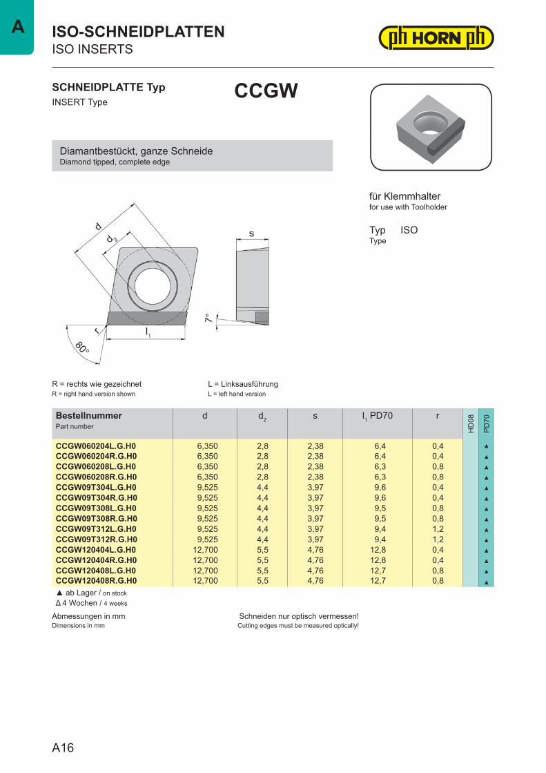
CCGW060204L.G.H0 6,350 2,8 2,38 6,4 0,4 ▲
CCGW060204R.G.H0 6,350 2,8 2,38 6,4 0,4 ▲
CCGW060208L.G.H0 6,350 2,8 2,38 6,3 0,8 ▲
CCGW060208R.G.H0 6,350 2,8 2,38 6,3 0,8 ▲
CCGW09T304L.G.H0 9,525 4,4 3,97 9,6 0,4 ▲
CCGW09T304R.G.H0 9,525 4,4 3,97 9,6 0,4 ▲
CCGW09T308L.G.H0 9,525 4,4 3,97 9,5 0,8 ▲
CCGW09T308R.G.H0 9,525 4,4 3,97 9,5 0,8 ▲
CCGW09T312L.G.H0 9,525 4,4 3,97 9,4 1,2 ▲
CCGW09T312R.G.H0 9,525 4,4 3,97 9,4 1,2 ▲
CCGW120404L.G.H0 12,700 5,5 4,76 12,8 0,4 ▲
CCGW120404R.G.H0 12,700 5,5 4,76 12,8 0,4 ▲
CCGW120408L.G.H0 12,700 5,5 4,76 12,7 0,8 ▲
CCGW120408R.G.H0 12,700 5,5 4,76 12,7 0,8 ▲
▲ ab Lager / on stockΔ 4 Wochen / 4 weeks
SCHNEIDPLATTE TypINSERT Type
CCGW
ISO-SCHNEIDPLATTENISO INSERTS
for use with Toolholder
TypType
ISO
R = rechts wie gezeichnetR = right hand version shown
L = LinksausführungL = left hand version
für Klemmhalter
Diamantbestückt, ganze SchneideDiamond tipped, complete edge
A16
A
Abmessungen in mmDimensions in mm
Schneiden nur optisch vermessen!Cutting edges must be measured optically!
BestellnummerPart number
d d2 s l1 HD08 l1 PD70 r
HD
08
PD
70
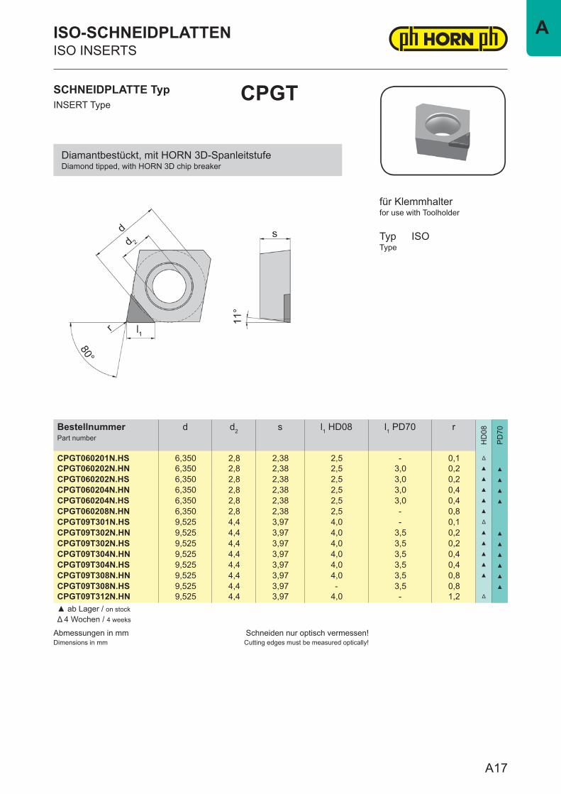
CPGT060201N.HS 6,350 2,8 2,38 2,5 - 0,1 Δ
CPGT060202N.HN 6,350 2,8 2,38 2,5 3,0 0,2 ▲ ▲
CPGT060202N.HS 6,350 2,8 2,38 2,5 3,0 0,2 ▲ ▲
CPGT060204N.HN 6,350 2,8 2,38 2,5 3,0 0,4 ▲ ▲
CPGT060204N.HS 6,350 2,8 2,38 2,5 3,0 0,4 ▲ ▲
CPGT060208N.HN 6,350 2,8 2,38 2,5 - 0,8 ▲
CPGT09T301N.HS 9,525 4,4 3,97 4,0 - 0,1 Δ
CPGT09T302N.HN 9,525 4,4 3,97 4,0 3,5 0,2 ▲ ▲
CPGT09T302N.HS 9,525 4,4 3,97 4,0 3,5 0,2 ▲ ▲
CPGT09T304N.HN 9,525 4,4 3,97 4,0 3,5 0,4 ▲ ▲
CPGT09T304N.HS 9,525 4,4 3,97 4,0 3,5 0,4 ▲ ▲
CPGT09T308N.HN 9,525 4,4 3,97 4,0 3,5 0,8 ▲ ▲
CPGT09T308N.HS 9,525 4,4 3,97 - 3,5 0,8 ▲
CPGT09T312N.HN 9,525 4,4 3,97 4,0 - 1,2 Δ
▲ ab Lager / on stockΔ 4 Wochen / 4 weeks
SCHNEIDPLATTE TypINSERT Type
CPGT
ISO-SCHNEIDPLATTENISO INSERTS
for use with Toolholder
TypType
ISO
für Klemmhalter
Diamantbestückt, mit HORN 3D-SpanleitstufeDiamond tipped, with HORN 3D chip breaker
A17
A
Abmessungen in mmDimensions in mm
Schneiden nur optisch vermessen!Cutting edges must be measured optically!
BestellnummerPart number
d d2 s l1 PD70 r
HD
08
PD
70
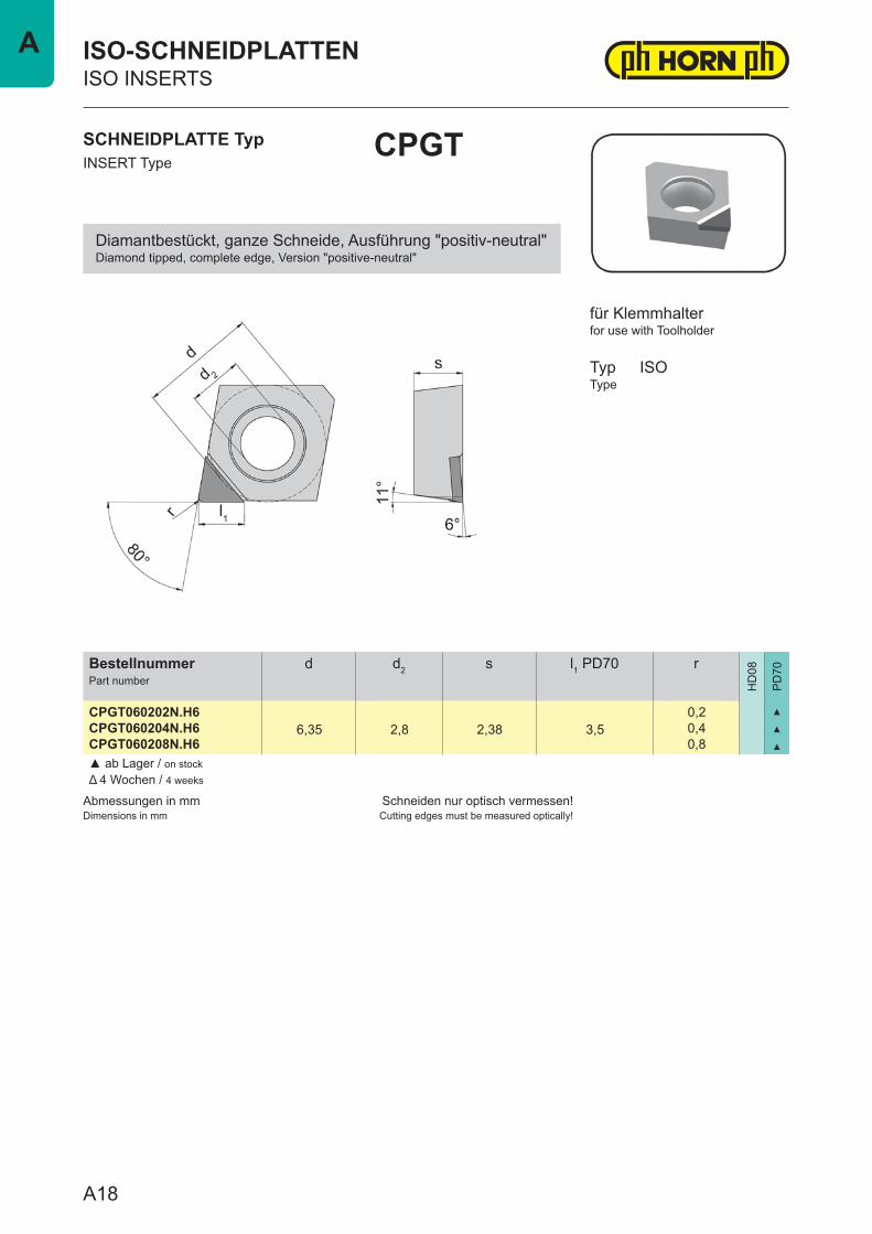
CPGT060202N.H66,35 2,8 2,38 3,5
0,2 ▲
CPGT060204N.H6 0,4 ▲
CPGT060208N.H6 0,8 ▲
▲ ab Lager / on stockΔ 4 Wochen / 4 weeks
SCHNEIDPLATTE TypINSERT Type
CPGT
ISO-SCHNEIDPLATTENISO INSERTS
for use with Toolholder
TypType
ISO
für Klemmhalter
Diamantbestückt, ganze Schneide, Ausführung "positiv-neutral"Diamond tipped, complete edge, Version "positive-neutral"
A18
A
Abmessungen in mmDimensions in mm
Schneiden nur optisch vermessen!Cutting edges must be measured optically!
BestellnummerPart number
d d2 s l1 PD70 r
HD
08
PD
70
CPGT060202N.W.HN 6,350 2,8 2,38 3,0 0,2 ▲
CPGT060202N.W.HS 6,350 2,8 2,38 3,0 0,2 ▲
CPGT060204N.W.HN 6,350 2,8 2,38 3,0 0,4 ▲
CPGT060204N.W.HS 6,350 2,8 2,38 3,0 0,4 ▲
CPGT09T302N.W.HN 9,525 4,4 3,97 3,5 0,2 ▲
CPGT09T302N.W.HS 9,525 4,4 3,97 3,5 0,2 ▲
CPGT09T304N.W.HN 9,525 4,4 3,97 3,5 0,4 ▲
CPGT09T304N.W.HS 9,525 4,4 3,97 3,5 0,4 ▲
▲ ab Lager / on stockΔ 4 Wochen / 4 weeks
SCHNEIDPLATTE TypINSERT Type
CPGT
ISO-SCHNEIDPLATTENISO INSERTS
for use with Toolholder
TypType
ISO
für Klemmhalter
Diamantbestückt, Wiper Geometrie mit HORN 3D-SpanleitstufeDiamond tipped, Wiper geometry with HORN 3D chip breaker
Anstellwinkel beachten!Siehe Seite J5
Please note the approach angle!See page J5
A19
A
Abmessungen in mmDimensions in mm
Schneiden nur optisch vermessen!Cutting edges must be measured optically!
BestellnummerPart number
d d2 s l1 PD70 r
HD
08
PD
70
CPGW060202N.H0 6,350 2,8 2,38 3,5 0,2 ▲
CPGW060204N.H0 6,350 2,8 2,38 3,5 0,4 ▲
CPGW060208N.H0 6,350 2,8 2,38 3,5 0,8 ▲
CPGW09T302N.H0 9,525 4,4 3,97 4,0 0,2 ▲
CPGW09T304N.H0 9,525 4,4 3,97 4,0 0,4 ▲
CPGW09T308N.H0 9,525 4,4 3,97 4,0 0,8 ▲
CPGW120402N.H0 12,700 5,5 4,76 4,0 0,2 ▲
CPGW120404N.H0 12,700 5,5 4,76 4,0 0,4 ▲
CPGW120408N.H0 12,700 5,5 4,76 4,0 0,8 ▲
▲ ab Lager / on stockΔ 4 Wochen / 4 weeks
SCHNEIDPLATTE TypINSERT Type
CPGW
ISO-SCHNEIDPLATTENISO INSERTS
for use with Toolholder
TypType
ISO
für Klemmhalter
Diamantbestückt, Ausführung "neutral"Diamond tipped, Version "neutral"
A20
A
Abmessungen in mmDimensions in mm
Schneiden nur optisch vermessen!Cutting edges must be measured optically!
BestellnummerPart number
d d2 s l1 PD70 r
HD
08
PD
70
CPGW060202N.W.H0 6,350 2,8 2,38 3,5 0,1 ▲
CPGW060204N.W.H0 6,350 2,8 2,38 3,5 0,4 ▲
CPGW09T302N.W.H0 9,525 4,4 3,97 4,0 0,2 ▲
CPGW09T304N.W.H0 9,525 4,4 3,97 4,0 0,4 ▲
CPGW120402N.W.H0 12,700 5,5 4,76 4,0 0,2 ▲
CPGW120404N.W.H0 12,700 5,5 4,76 4,0 0,4 ▲
▲ ab Lager / on stockΔ 4 Wochen / 4 weeks
SCHNEIDPLATTE TypINSERT Type
CPGW
ISO-SCHNEIDPLATTENISO INSERTS
for use with Toolholder
TypType
ISO
für Klemmhalter
Diamantbestückt, Wiper Geometrie, Ausführung "neutral"Diamond tipped, Wiper geometry, Version "neutral"
Anstellwinkel beachten!Siehe Seite J5
Please note the approach angle!See page J5
A21
A
Abmessungen in mmDimensions in mm
Schneiden nur optisch vermessen!Cutting edges must be measured optically!
HM-SortenCarbide grades
BestellnummerPart number
d d2 s l1 PD70 r
HD
08
PD
70
CPGW060204L.G.H0 6,350 2,8 2,38 6,4 0,4 ▲
CPGW060204R.G.H0 6,350 2,8 2,38 6,4 0,4 ▲
CPGW060208L.G.H0 6,350 2,8 2,38 6,3 0,8 ▲
CPGW060208R.G.H0 6,350 2,8 2,38 6,3 0,8 ▲
CPGW09T308L.G.H0 9,525 4,4 3,97 9,5 0,8 ▲
CPGW09T308R.G.H0 9,525 4,4 3,97 9,5 0,8 ▲
CPGW120408L.G.H0 12,700 5,5 4,76 12,7 0,8 ▲
CPGW120408R.G.H0 12,700 5,5 4,76 12,7 0,8 ▲
CPGW120412L.G.H0 12,700 5,5 4,76 12,6 1,2 ▲
CPGW120412R.G.H0 12,700 5,5 4,76 12,6 1,2 ▲
▲ ab Lager / on stockΔ 4 Wochen / 4 weeks
SCHNEIDPLATTE TypINSERT Type
CPGW
ISO-SCHNEIDPLATTENISO INSERTS
for use with Toolholder
TypType
ISO
R = rechts wie gezeichnetR = right hand version shown
L = links spiegelbildlichL = left hand version
für Klemmhalter
Diamantbestückt, ganze SchneideDiamond tipped, complete edge
A22
A
Abmessungen in mmDimensions in mm
Schneiden nur optisch vermessen!Cutting edges must be measured optically!
BestellnummerPart number
d d2 s l1 HD08 l1 PD70 r
HD
08
PD
70
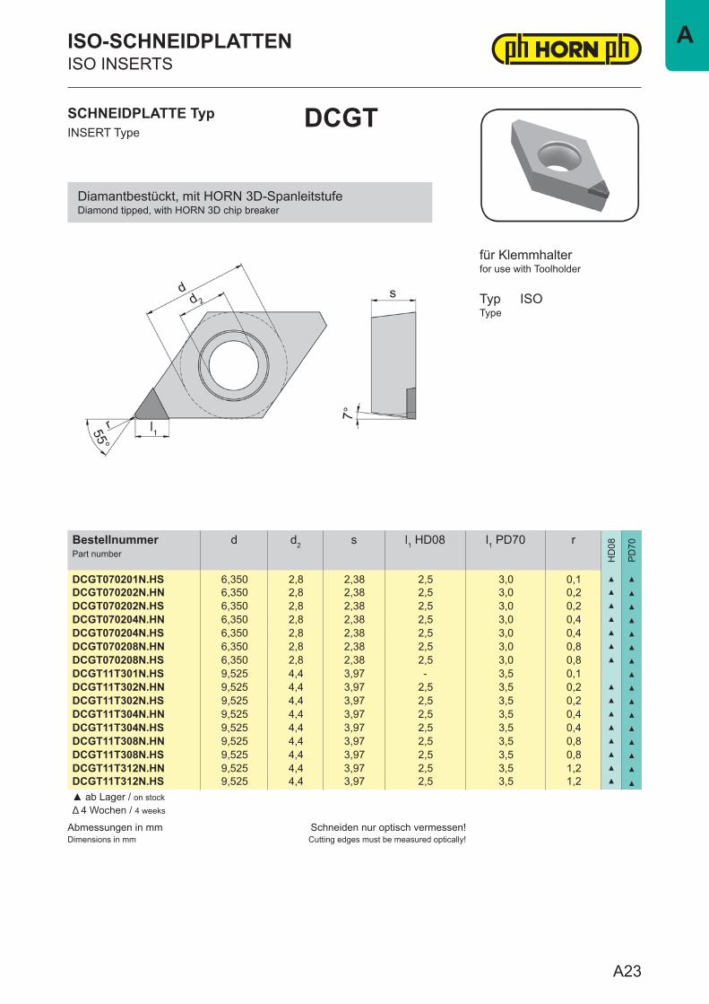
DCGT070201N.HS 6,350 2,8 2,38 2,5 3,0 0,1 ▲ ▲
DCGT070202N.HN 6,350 2,8 2,38 2,5 3,0 0,2 ▲ ▲
DCGT070202N.HS 6,350 2,8 2,38 2,5 3,0 0,2 ▲ ▲
DCGT070204N.HN 6,350 2,8 2,38 2,5 3,0 0,4 ▲ ▲
DCGT070204N.HS 6,350 2,8 2,38 2,5 3,0 0,4 ▲ ▲
DCGT070208N.HN 6,350 2,8 2,38 2,5 3,0 0,8 ▲ ▲
DCGT070208N.HS 6,350 2,8 2,38 2,5 3,0 0,8 ▲ ▲
DCGT11T301N.HS 9,525 4,4 3,97 - 3,5 0,1 ▲
DCGT11T302N.HN 9,525 4,4 3,97 2,5 3,5 0,2 ▲ ▲
DCGT11T302N.HS 9,525 4,4 3,97 2,5 3,5 0,2 ▲ ▲
DCGT11T304N.HN 9,525 4,4 3,97 2,5 3,5 0,4 ▲ ▲
DCGT11T304N.HS 9,525 4,4 3,97 2,5 3,5 0,4 ▲ ▲
DCGT11T308N.HN 9,525 4,4 3,97 2,5 3,5 0,8 ▲ ▲
DCGT11T308N.HS 9,525 4,4 3,97 2,5 3,5 0,8 ▲ ▲
DCGT11T312N.HN 9,525 4,4 3,97 2,5 3,5 1,2 ▲ ▲
DCGT11T312N.HS 9,525 4,4 3,97 2,5 3,5 1,2 ▲ ▲
▲ ab Lager / on stockΔ 4 Wochen / 4 weeks
SCHNEIDPLATTE TypINSERT Type
DCGT
ISO-SCHNEIDPLATTENISO INSERTS
for use with Toolholder
TypType
ISO
für Klemmhalter
Diamantbestückt, mit HORN 3D-SpanleitstufeDiamond tipped, with HORN 3D chip breaker
A23
A
Abmessungen in mmDimensions in mm
Schneiden nur optisch vermessen!Cutting edges must be measured optically!
BestellnummerPart number
d d2 s l1 HD08 l1 PD70 r
HD
08
PD
70
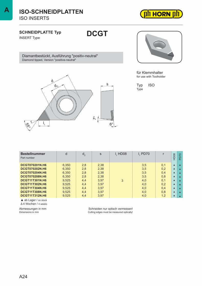
DCGT070201N.H6 6,350 2,8 2,38
3
3,5 0,1 ▲ ▲
DCGT070202N.H6 6,350 2,8 2,38 3,5 0,2 ▲ ▲
DCGT070204N.H6 6,350 2,8 2,38 3,5 0,4 ▲ ▲
DCGT070208N.H6 6,350 2,8 2,38 3,5 0,8 ▲ ▲
DCGT11T301N.H6 9,525 4,4 3,97 4,0 0,1 ▲ ▲
DCGT11T302N.H6 9,525 4,4 3,97 4,0 0,2 ▲ ▲
DCGT11T304N.H6 9,525 4,4 3,97 4,0 0,4 ▲ ▲
DCGT11T308N.H6 9,525 4,4 3,97 4,0 0,8 ▲ ▲
DCGT11T312N.H6 9,525 4,4 3,97 4,0 1,2 ▲ ▲
▲ ab Lager / on stockΔ 4 Wochen / 4 weeks
SCHNEIDPLATTE TypINSERT Type
DCGT
ISO-SCHNEIDPLATTENISO INSERTS
for use with Toolholder
TypType
ISO
für Klemmhalter
Diamantbestückt, Ausführung "positiv-neutral"Diamond tipped, Version "positive-neutral"
A24
A
Abmessungen in mmDimensions in mm
Schneiden nur optisch vermessen!Cutting edges must be measured optically!
BestellnummerPart number
d d2 s l1 HD08 l1 PD70 r
HD
08
PD
70
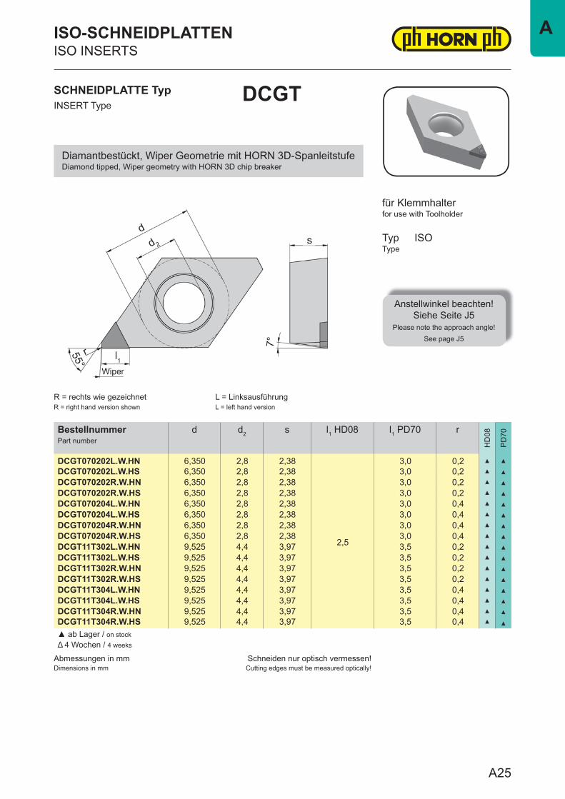
DCGT070202L.W.HN 6,350 2,8 2,38
2,5
3,0 0,2 ▲ ▲
DCGT070202L.W.HS 6,350 2,8 2,38 3,0 0,2 ▲ ▲
DCGT070202R.W.HN 6,350 2,8 2,38 3,0 0,2 ▲ ▲
DCGT070202R.W.HS 6,350 2,8 2,38 3,0 0,2 ▲ ▲
DCGT070204L.W.HN 6,350 2,8 2,38 3,0 0,4 ▲ ▲
DCGT070204L.W.HS 6,350 2,8 2,38 3,0 0,4 ▲ ▲
DCGT070204R.W.HN 6,350 2,8 2,38 3,0 0,4 ▲ ▲
DCGT070204R.W.HS 6,350 2,8 2,38 3,0 0,4 ▲ ▲
DCGT11T302L.W.HN 9,525 4,4 3,97 3,5 0,2 ▲ ▲
DCGT11T302L.W.HS 9,525 4,4 3,97 3,5 0,2 ▲ ▲
DCGT11T302R.W.HN 9,525 4,4 3,97 3,5 0,2 ▲ ▲
DCGT11T302R.W.HS 9,525 4,4 3,97 3,5 0,2 ▲ ▲
DCGT11T304L.W.HN 9,525 4,4 3,97 3,5 0,4 ▲ ▲
DCGT11T304L.W.HS 9,525 4,4 3,97 3,5 0,4 ▲ ▲
DCGT11T304R.W.HN 9,525 4,4 3,97 3,5 0,4 ▲ ▲
DCGT11T304R.W.HS 9,525 4,4 3,97 3,5 0,4 ▲ ▲
▲ ab Lager / on stockΔ 4 Wochen / 4 weeks
SCHNEIDPLATTE TypINSERT Type
DCGT
ISO-SCHNEIDPLATTENISO INSERTS
for use with Toolholder
TypType
ISO
R = rechts wie gezeichnetR = right hand version shown
L = LinksausführungL = left hand version
für Klemmhalter
Diamantbestückt, Wiper Geometrie mit HORN 3D-SpanleitstufeDiamond tipped, Wiper geometry with HORN 3D chip breaker
Anstellwinkel beachten!Siehe Seite J5
Please note the approach angle!See page J5
A25
A
Abmessungen in mmDimensions in mm
Schneiden nur optisch vermessen!Cutting edges must be measured optically!
BestellnummerPart number
d d2 s l1 PD70 r
HD
08
PD
70
DCGT070202L.W.H6 6,350 2,8 2,38 3,5 0,2 ▲
DCGT070202R.W.H6 6,350 2,8 2,38 3,5 0,2 ▲
DCGT070204L.W.H6 6,350 2,8 2,38 3,3 0,4 ▲
DCGT070204R.W.H6 6,350 2,8 2,38 3,3 0,4 ▲
DCGT11T302L.W.H6 9,525 4,4 3,97 4,0 0,2 ▲
DCGT11T302R.W.H6 9,525 4,4 3,97 4,0 0,2 ▲
DCGT11T304L.W.H6 9,525 4,4 3,97 3,8 0,4 ▲
DCGT11T304R.W.H6 9,525 4,4 3,97 3,8 0,4 ▲
▲ ab Lager / on stockΔ 4 Wochen / 4 weeks
SCHNEIDPLATTE TypINSERT Type
DCGT
ISO-SCHNEIDPLATTENISO INSERTS
for use with Toolholder
TypType
ISO
R = rechts wie gezeichnetR = right hand version shown
L = links spiegelbildlichL = left hand version
für Klemmhalter
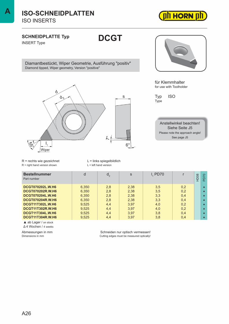
Diamantbestückt, Wiper Geometrie, Ausführung "positiv"Diamond tipped, Wiper geometry, Version "positive"
Anstellwinkel beachten!Siehe Seite J5
Please note the approach angle!See page J5
A26
A
Abmessungen in mmDimensions in mm
Schneiden nur optisch vermessen!Cutting edges must be measured optically!
BestellnummerPart number
d d2 s l1 HD08 l1 PD70 r
HD
08
PD
70
DCGW070201N.H0 6,350 2,8 2,38 3 3,5 0,1 Δ ▲
DCGW070202N.H0 6,350 2,8 2,38 3 3,5 0,2 ▲ ▲
DCGW070204N.H0 6,350 2,8 2,38 3 3,5 0,4 ▲ ▲
DCGW070208N.H0 6,350 2,8 2,38 3 3,5 0,8 ▲ ▲
DCGW11T301N.H0 9,525 4,4 3,97 3 4,0 0,1 Δ ▲
DCGW11T302N.H0 9,525 4,4 3,97 3 4,0 0,2 ▲ ▲
DCGW11T304N.H0 9,525 4,4 3,97 3 4,0 0,4 ▲ ▲
DCGW11T308N.H0 9,525 4,4 3,97 3 4,0 0,8 ▲ ▲
DCGW11T312N.H0 9,525 4,4 3,97 - 4,0 1,2 ▲
▲ ab Lager / on stockΔ 4 Wochen / 4 weeks
SCHNEIDPLATTE TypINSERT Type
DCGW
ISO-SCHNEIDPLATTENISO INSERTS
for use with Toolholder
TypType
ISO
für Klemmhalter
Diamantbestückt, Ausführung "neutral"Diamond tipped, Version "neutral"
A27
A
Abmessungen in mmDimensions in mm
Schneiden nur optisch vermessen!Cutting edges must be measured optically!
BestellnummerPart number
d d2 s l1 PD70 r
HD
08
PD
70
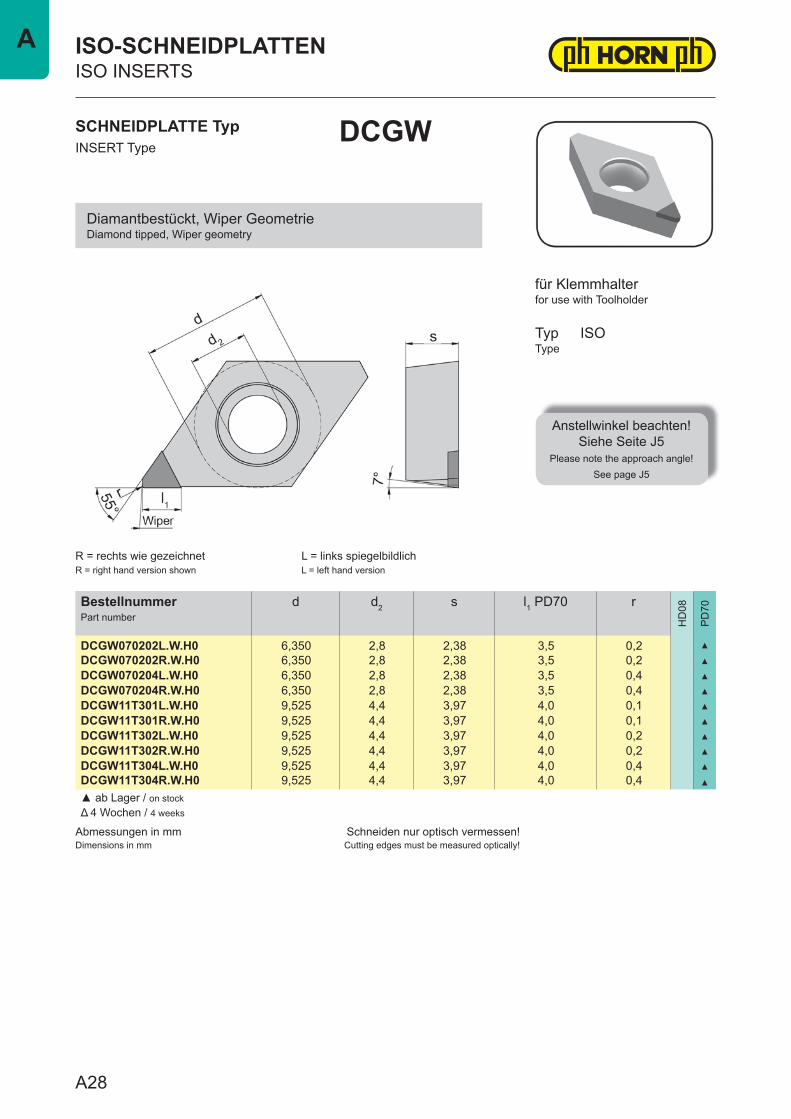
DCGW070202L.W.H0 6,350 2,8 2,38 3,5 0,2 ▲
DCGW070202R.W.H0 6,350 2,8 2,38 3,5 0,2 ▲
DCGW070204L.W.H0 6,350 2,8 2,38 3,5 0,4 ▲
DCGW070204R.W.H0 6,350 2,8 2,38 3,5 0,4 ▲
DCGW11T301L.W.H0 9,525 4,4 3,97 4,0 0,1 ▲
DCGW11T301R.W.H0 9,525 4,4 3,97 4,0 0,1 ▲
DCGW11T302L.W.H0 9,525 4,4 3,97 4,0 0,2 ▲
DCGW11T302R.W.H0 9,525 4,4 3,97 4,0 0,2 ▲
DCGW11T304L.W.H0 9,525 4,4 3,97 4,0 0,4 ▲
DCGW11T304R.W.H0 9,525 4,4 3,97 4,0 0,4 ▲
▲ ab Lager / on stockΔ 4 Wochen / 4 weeks
SCHNEIDPLATTE TypINSERT Type
DCGW
ISO-SCHNEIDPLATTENISO INSERTS
for use with Toolholder
TypType
ISO
R = rechts wie gezeichnetR = right hand version shown
L = links spiegelbildlichL = left hand version
für Klemmhalter
Diamantbestückt, Wiper GeometrieDiamond tipped, Wiper geometry
Anstellwinkel beachten!Siehe Seite J5
Please note the approach angle!See page J5
A28
A
Abmessungen in mmDimensions in mm
Schneiden nur optisch vermessen!Cutting edges must be measured optically!
BestellnummerPart number
d d2 s
HD
08
PD
70
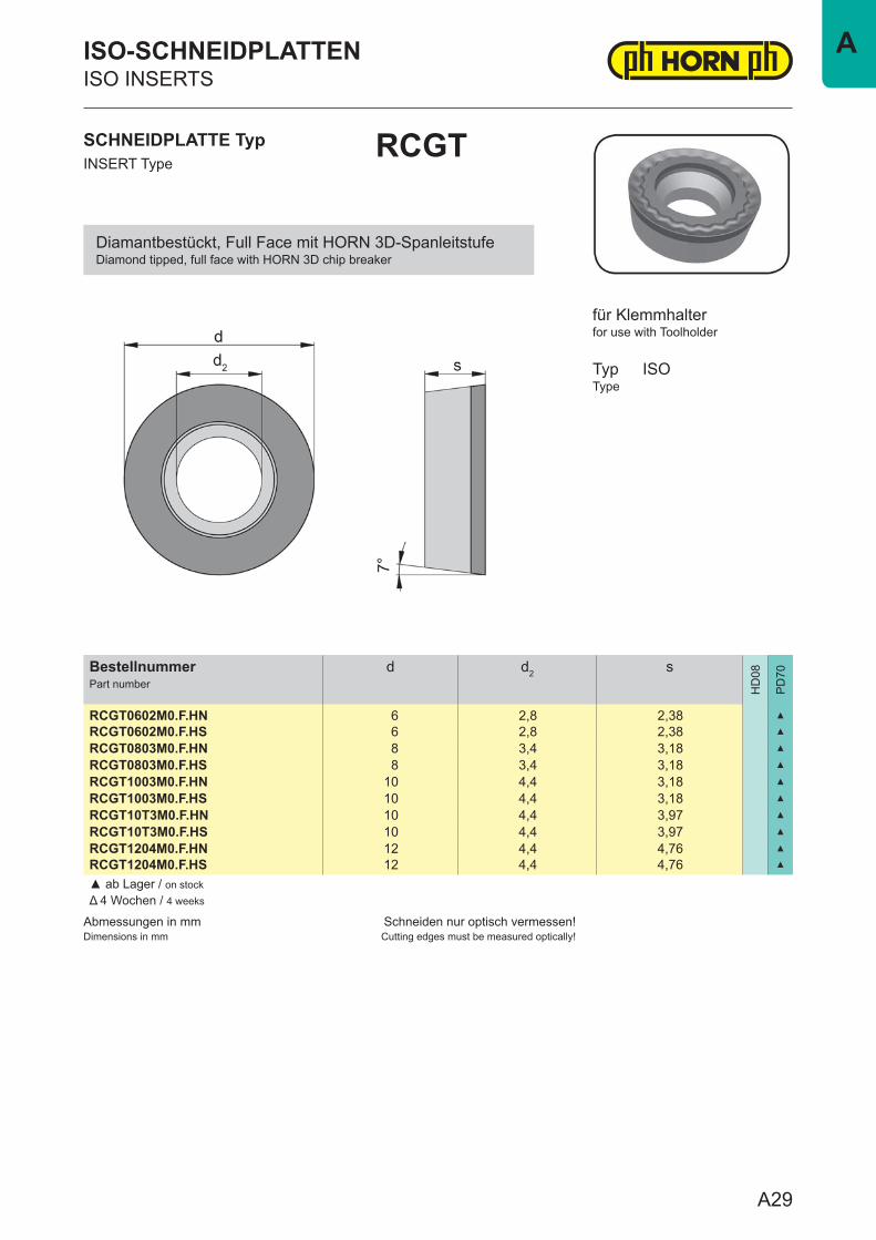
RCGT0602M0.F.HN 6 2,8 2,38 ▲
RCGT0602M0.F.HS 6 2,8 2,38 ▲
RCGT0803M0.F.HN 8 3,4 3,18 ▲
RCGT0803M0.F.HS 8 3,4 3,18 ▲
RCGT1003M0.F.HN 10 4,4 3,18 ▲
RCGT1003M0.F.HS 10 4,4 3,18 ▲
RCGT10T3M0.F.HN 10 4,4 3,97 ▲
RCGT10T3M0.F.HS 10 4,4 3,97 ▲
RCGT1204M0.F.HN 12 4,4 4,76 ▲
RCGT1204M0.F.HS 12 4,4 4,76 ▲
▲ ab Lager / on stockΔ 4 Wochen / 4 weeks
SCHNEIDPLATTE TypINSERT Type
RCGT
ISO-SCHNEIDPLATTENISO INSERTS
for use with Toolholder
TypType
ISO
für Klemmhalter
Diamantbestückt, Full Face mit HORN 3D-SpanleitstufeDiamond tipped, full face with HORN 3D chip breaker
A29
A
Abmessungen in mmDimensions in mm
Schneiden nur optisch vermessen!Cutting edges must be measured optically!
BestellnummerPart number
d d2 s
HD
08
PD
70
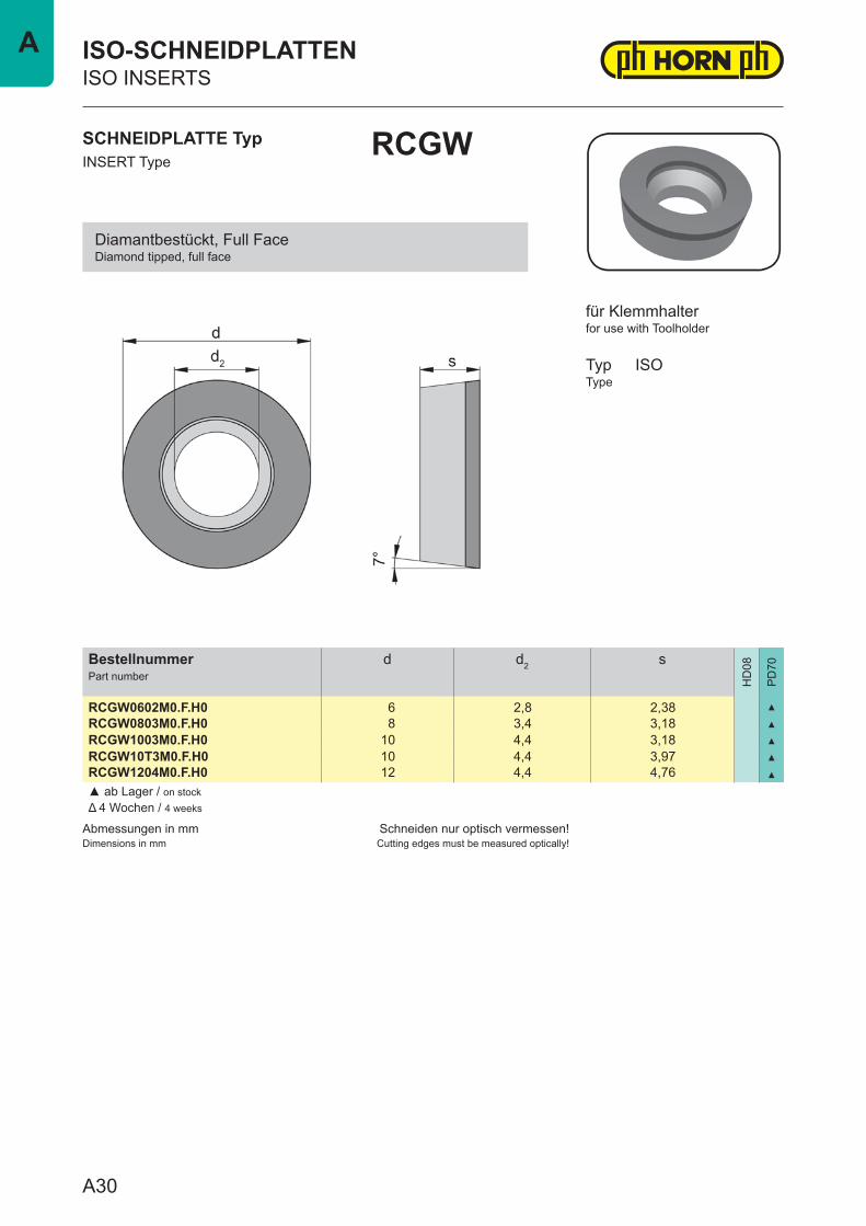
RCGW0602M0.F.H0 6 2,8 2,38 ▲
RCGW0803M0.F.H0 8 3,4 3,18 ▲
RCGW1003M0.F.H0 10 4,4 3,18 ▲
RCGW10T3M0.F.H0 10 4,4 3,97 ▲
RCGW1204M0.F.H0 12 4,4 4,76 ▲
▲ ab Lager / on stockΔ 4 Wochen / 4 weeks
SCHNEIDPLATTE TypINSERT Type
RCGW
ISO-SCHNEIDPLATTENISO INSERTS
for use with Toolholder
TypType
ISO
für Klemmhalter
Diamantbestückt, Full FaceDiamond tipped, full face
A30
A
Abmessungen in mmDimensions in mm
Schneiden nur optisch vermessen!Cutting edges must be measured optically!
BestellnummerPart number
d d2 s
HD
08
PD
70
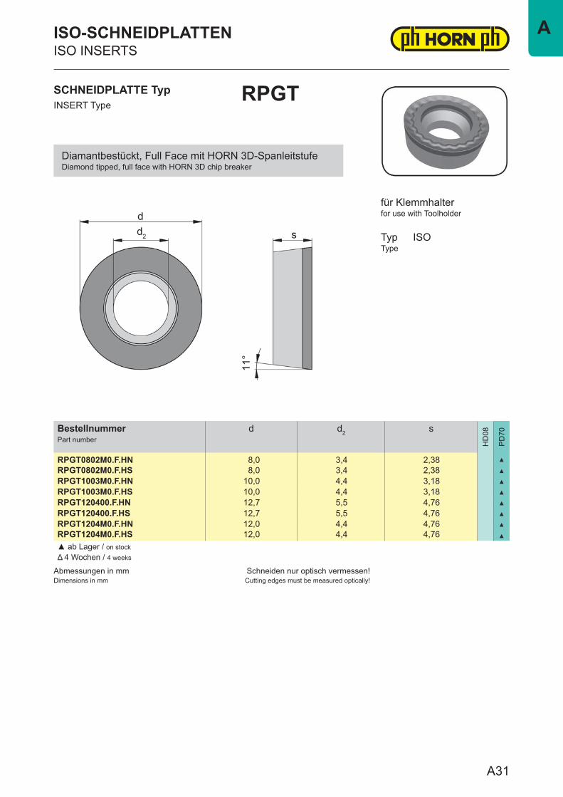
RPGT0802M0.F.HN 8,0 3,4 2,38 ▲
RPGT0802M0.F.HS 8,0 3,4 2,38 ▲
RPGT1003M0.F.HN 10,0 4,4 3,18 ▲
RPGT1003M0.F.HS 10,0 4,4 3,18 ▲
RPGT120400.F.HN 12,7 5,5 4,76 ▲
RPGT120400.F.HS 12,7 5,5 4,76 ▲
RPGT1204M0.F.HN 12,0 4,4 4,76 ▲
RPGT1204M0.F.HS 12,0 4,4 4,76 ▲
▲ ab Lager / on stockΔ 4 Wochen / 4 weeks
SCHNEIDPLATTE TypINSERT Type
RPGT
ISO-SCHNEIDPLATTENISO INSERTS
for use with Toolholder
TypType
ISO
für Klemmhalter
Diamantbestückt, Full Face mit HORN 3D-SpanleitstufeDiamond tipped, full face with HORN 3D chip breaker
A31
A
Abmessungen in mmDimensions in mm
Schneiden nur optisch vermessen!Cutting edges must be measured optically!
BestellnummerPart number
d d2 s
HD
08
PD
70
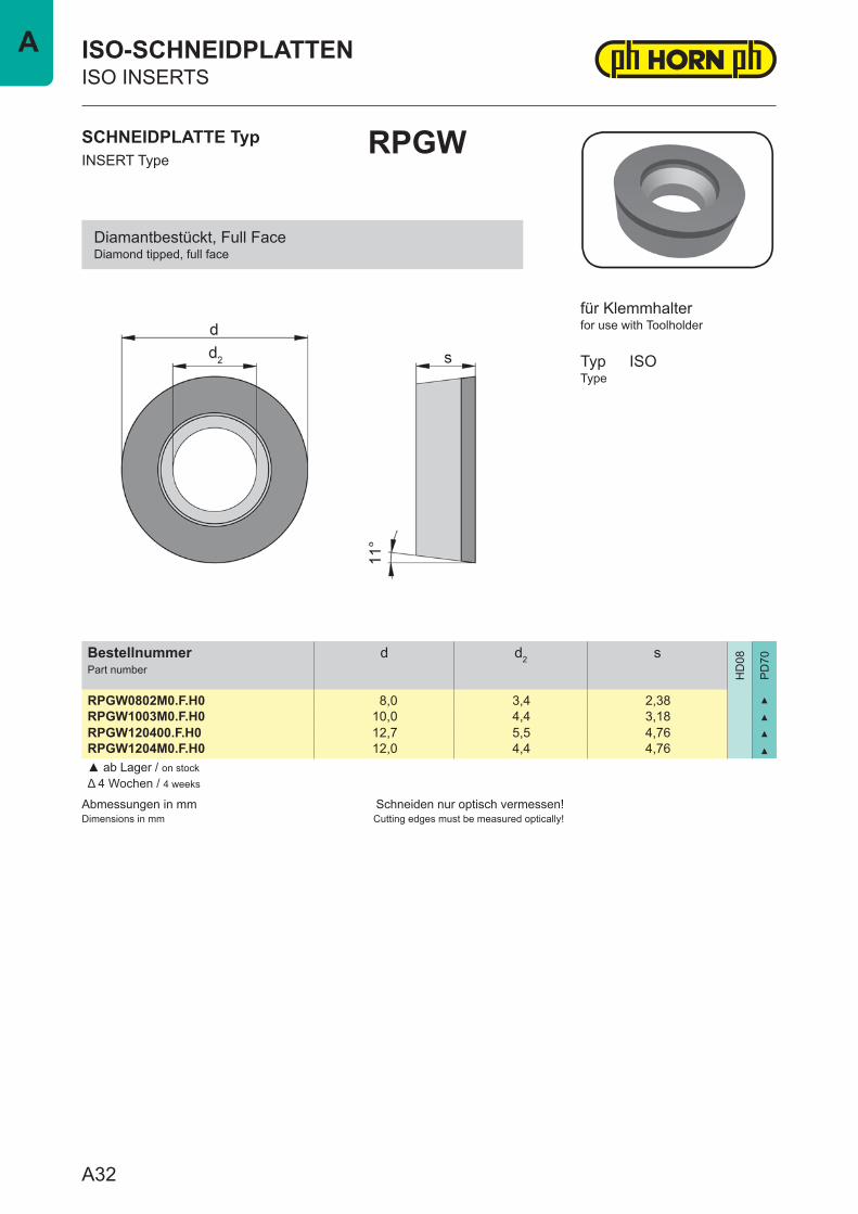
RPGW0802M0.F.H0 8,0 3,4 2,38 ▲
RPGW1003M0.F.H0 10,0 4,4 3,18 ▲
RPGW120400.F.H0 12,7 5,5 4,76 ▲
RPGW1204M0.F.H0 12,0 4,4 4,76 ▲
▲ ab Lager / on stockΔ 4 Wochen / 4 weeks
SCHNEIDPLATTE TypINSERT Type
RPGW
ISO-SCHNEIDPLATTENISO INSERTS
for use with Toolholder
TypType
ISO
für Klemmhalter
Diamantbestückt, Full FaceDiamond tipped, full face
A32
A
Abmessungen in mmDimensions in mm
Schneiden nur optisch vermessen!Cutting edges must be measured optically!
BestellnummerPart number
d d2 s l1 PD70 r
HD
08
PD
70
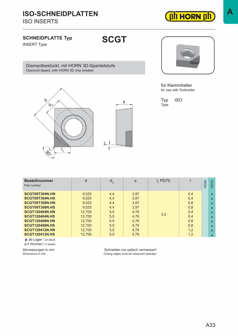
SCGT09T304N.HN 9,525 4,4 3,97
3,5
0,4 ▲
SCGT09T304N.HS 9,525 4,4 3,97 0,4 ▲
SCGT09T308N.HN 9,525 4,4 3,97 0,8 ▲
SCGT09T308N.HS 9,525 4,4 3,97 0,8 ▲
SCGT120404N.HN 12,700 5,5 4,76 0,4 ▲
SCGT120404N.HS 12,700 5,5 4,76 0,4 ▲
SCGT120408N.HN 12,700 5,5 4,76 0,8 ▲
SCGT120408N.HS 12,700 5,5 4,76 0,8 ▲
SCGT120412N.HN 12,700 5,5 4,76 1,2 ▲
SCGT120412N.HS 12,700 5,5 4,76 1,2 ▲
▲ ab Lager / on stockΔ 4 Wochen / 4 weeks
SCHNEIDPLATTE TypINSERT Type
SCGT
ISO-SCHNEIDPLATTENISO INSERTS
for use with Toolholder
TypType
ISO
für Klemmhalter
Diamantbestückt, mit HORN 3D-SpanleitstufeDiamond tipped, with HORN 3D chip breaker
A33
A
Abmessungen in mmDimensions in mm
Schneiden nur optisch vermessen!Cutting edges must be measured optically!
BestellnummerPart number
d d2 s l1 PD70 r
HD
08
PD
70
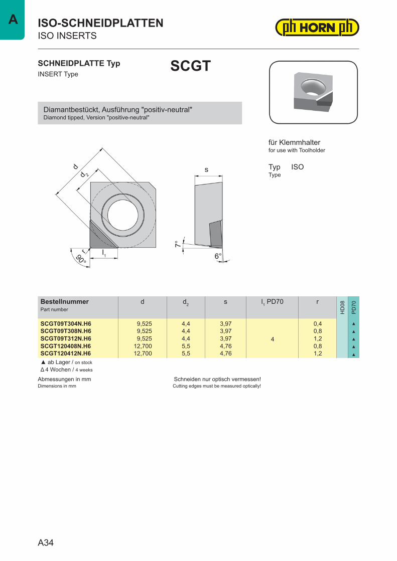
SCGT09T304N.H6 9,525 4,4 3,97
4
0,4 ▲
SCGT09T308N.H6 9,525 4,4 3,97 0,8 ▲
SCGT09T312N.H6 9,525 4,4 3,97 1,2 ▲
SCGT120408N.H6 12,700 5,5 4,76 0,8 ▲
SCGT120412N.H6 12,700 5,5 4,76 1,2 ▲
▲ ab Lager / on stockΔ 4 Wochen / 4 weeks
SCHNEIDPLATTE TypINSERT Type
SCGT
ISO-SCHNEIDPLATTENISO INSERTS
for use with Toolholder
TypType
ISO
für Klemmhalter
Diamantbestückt, Ausführung "positiv-neutral"Diamond tipped, Version "positive-neutral"
A34
A
Abmessungen in mmDimensions in mm
Schneiden nur optisch vermessen!Cutting edges must be measured optically!
BestellnummerPart number
d d2 s l1 PD70 r
HD
08
PD
70
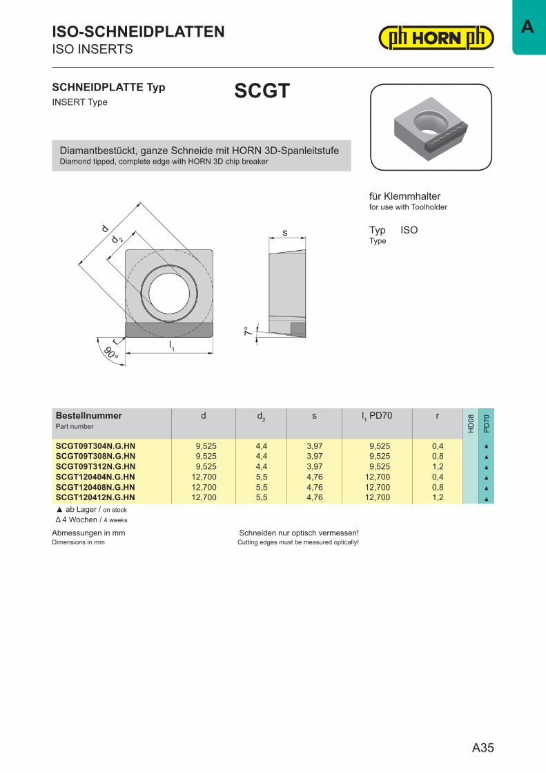
SCGT09T304N.G.HN 9,525 4,4 3,97 9,525 0,4 ▲
SCGT09T308N.G.HN 9,525 4,4 3,97 9,525 0,8 ▲
SCGT09T312N.G.HN 9,525 4,4 3,97 9,525 1,2 ▲
SCGT120404N.G.HN 12,700 5,5 4,76 12,700 0,4 ▲
SCGT120408N.G.HN 12,700 5,5 4,76 12,700 0,8 ▲
SCGT120412N.G.HN 12,700 5,5 4,76 12,700 1,2 ▲
▲ ab Lager / on stockΔ 4 Wochen / 4 weeks
SCHNEIDPLATTE TypINSERT Type
SCGT
ISO-SCHNEIDPLATTENISO INSERTS
for use with Toolholder
TypType
ISO
für Klemmhalter
Diamantbestückt, ganze Schneide mit HORN 3D-SpanleitstufeDiamond tipped, complete edge with HORN 3D chip breaker
A35
A
Abmessungen in mmDimensions in mm
Schneiden nur optisch vermessen!Cutting edges must be measured optically!
BestellnummerPart number
d d2 s l1 PD70 r
HD
08
PD
70
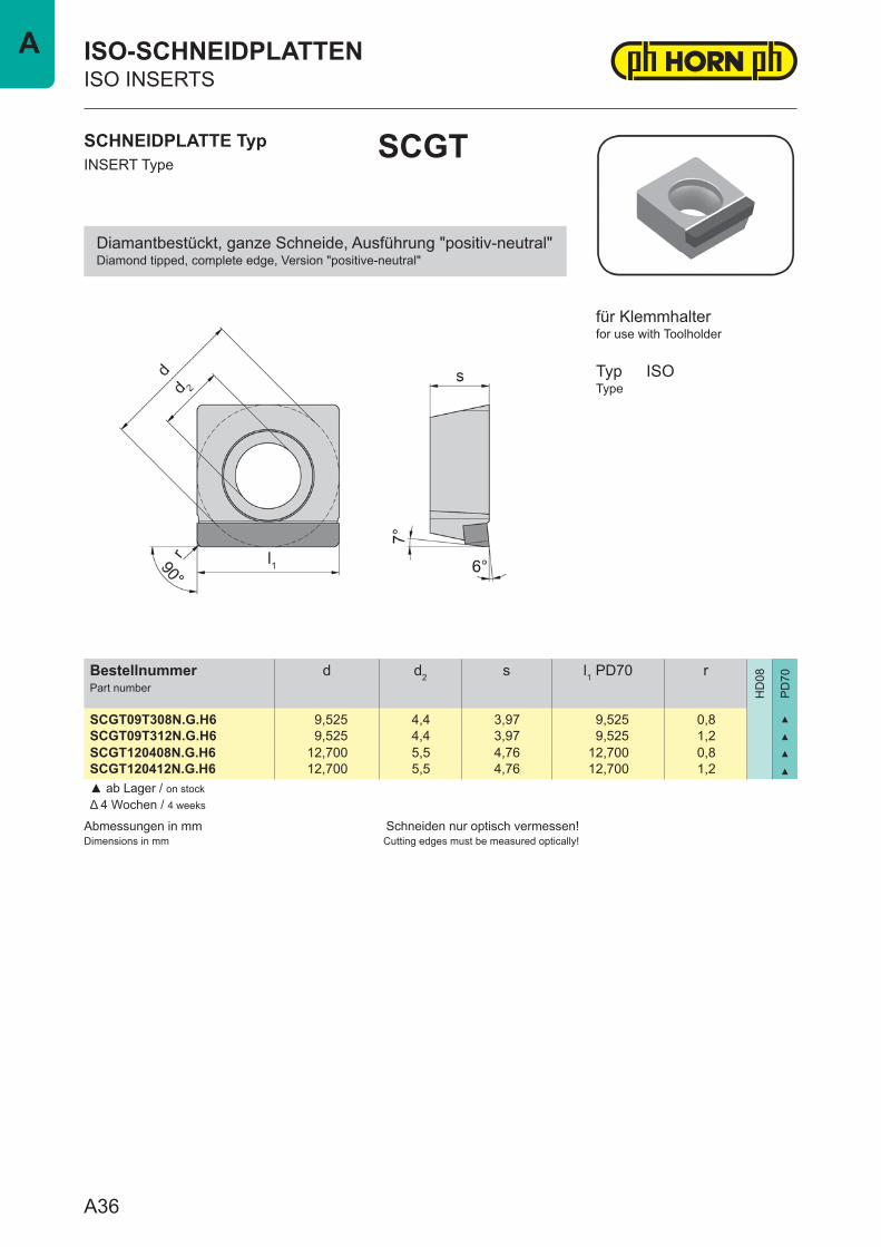
SCGT09T308N.G.H6 9,525 4,4 3,97 9,525 0,8 ▲
SCGT09T312N.G.H6 9,525 4,4 3,97 9,525 1,2 ▲
SCGT120408N.G.H6 12,700 5,5 4,76 12,700 0,8 ▲
SCGT120412N.G.H6 12,700 5,5 4,76 12,700 1,2 ▲
▲ ab Lager / on stockΔ 4 Wochen / 4 weeks
SCHNEIDPLATTE TypINSERT Type
SCGT
ISO-SCHNEIDPLATTENISO INSERTS
for use with Toolholder
TypType
ISO
für Klemmhalter
Diamantbestückt, ganze Schneide, Ausführung "positiv-neutral"Diamond tipped, complete edge, Version "positive-neutral"
A36
A
Abmessungen in mmDimensions in mm
Schneiden nur optisch vermessen!Cutting edges must be measured optically!
BestellnummerPart number
d d2 s l1 PD70 r
HD
08
PD
70
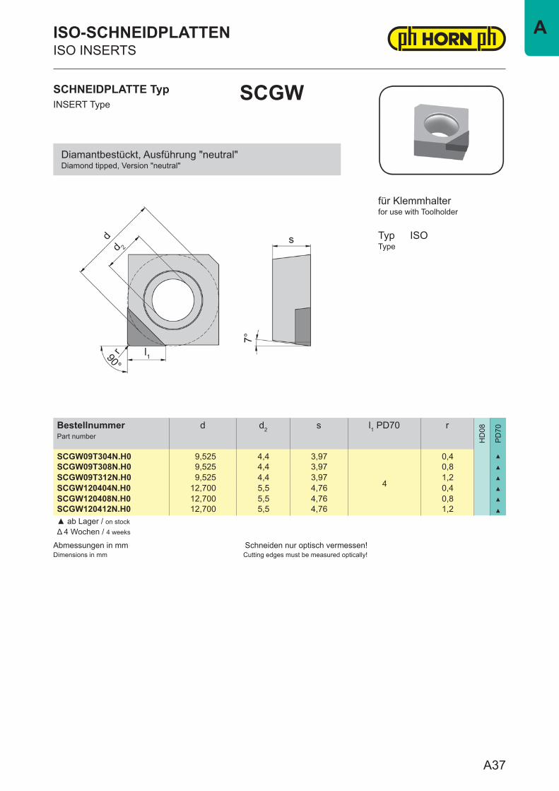
SCGW09T304N.H0 9,525 4,4 3,97
4
0,4 ▲
SCGW09T308N.H0 9,525 4,4 3,97 0,8 ▲
SCGW09T312N.H0 9,525 4,4 3,97 1,2 ▲
SCGW120404N.H0 12,700 5,5 4,76 0,4 ▲
SCGW120408N.H0 12,700 5,5 4,76 0,8 ▲
SCGW120412N.H0 12,700 5,5 4,76 1,2 ▲
▲ ab Lager / on stockΔ 4 Wochen / 4 weeks
SCHNEIDPLATTE TypINSERT Type
SCGW
ISO-SCHNEIDPLATTENISO INSERTS
for use with Toolholder
TypType
ISO
für Klemmhalter
Diamantbestückt, Ausführung "neutral"Diamond tipped, Version "neutral"
A37
A
Abmessungen in mmDimensions in mm
Schneiden nur optisch vermessen!Cutting edges must be measured optically!
BestellnummerPart number
d d2 s l1 PD70 r
HD
08
PD
70
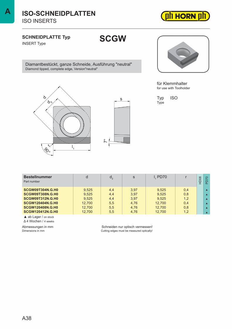
SCGW09T304N.G.H0 9,525 4,4 3,97 9,525 0,4 ▲
SCGW09T308N.G.H0 9,525 4,4 3,97 9,525 0,8 ▲
SCGW09T312N.G.H0 9,525 4,4 3,97 9,525 1,2 ▲
SCGW120404N.G.H0 12,700 5,5 4,76 12,700 0,4 ▲
SCGW120408N.G.H0 12,700 5,5 4,76 12,700 0,8 ▲
SCGW120412N.G.H0 12,700 5,5 4,76 12,700 1,2 ▲
▲ ab Lager / on stockΔ 4 Wochen / 4 weeks
SCHNEIDPLATTE TypINSERT Type
SCGW
ISO-SCHNEIDPLATTENISO INSERTS
for use with Toolholder
TypType
ISO
für Klemmhalter
Diamantbestückt, ganze Schneide, Ausführung "neutral"Diamond tipped, complete edge, Version"neutral"
A38
A
Abmessungen in mmDimensions in mm
Schneiden nur optisch vermessen!Cutting edges must be measured optically!
BestellnummerPart number
d d2 s l1 PD70 r
HD
08
PD
70
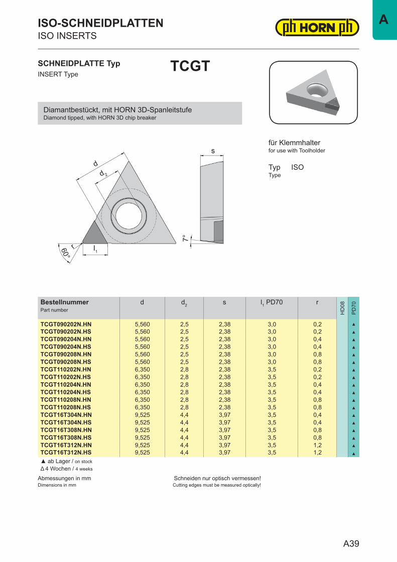
TCGT090202N.HN 5,560 2,5 2,38 3,0 0,2 ▲
TCGT090202N.HS 5,560 2,5 2,38 3,0 0,2 ▲
TCGT090204N.HN 5,560 2,5 2,38 3,0 0,4 ▲
TCGT090204N.HS 5,560 2,5 2,38 3,0 0,4 ▲
TCGT090208N.HN 5,560 2,5 2,38 3,0 0,8 ▲
TCGT090208N.HS 5,560 2,5 2,38 3,0 0,8 ▲
TCGT110202N.HN 6,350 2,8 2,38 3,5 0,2 ▲
TCGT110202N.HS 6,350 2,8 2,38 3,5 0,2 ▲
TCGT110204N.HN 6,350 2,8 2,38 3,5 0,4 ▲
TCGT110204N.HS 6,350 2,8 2,38 3,5 0,4 ▲
TCGT110208N.HN 6,350 2,8 2,38 3,5 0,8 ▲
TCGT110208N.HS 6,350 2,8 2,38 3,5 0,8 ▲
TCGT16T304N.HN 9,525 4,4 3,97 3,5 0,4 ▲
TCGT16T304N.HS 9,525 4,4 3,97 3,5 0,4 ▲
TCGT16T308N.HN 9,525 4,4 3,97 3,5 0,8 ▲
TCGT16T308N.HS 9,525 4,4 3,97 3,5 0,8 ▲
TCGT16T312N.HN 9,525 4,4 3,97 3,5 1,2 ▲
TCGT16T312N.HS 9,525 4,4 3,97 3,5 1,2 ▲
▲ ab Lager / on stockΔ 4 Wochen / 4 weeks
SCHNEIDPLATTE TypINSERT Type
TCGT
ISO-SCHNEIDPLATTENISO INSERTS
for use with Toolholder
TypType
ISO
für Klemmhalter
Diamantbestückt, mit HORN 3D-SpanleitstufeDiamond tipped, with HORN 3D chip breaker
A39
A
Abmessungen in mmDimensions in mm
Schneiden nur optisch vermessen!Cutting edges must be measured optically!
BestellnummerPart number
d d2 s l1 PD70 r
HD
08
PD
70
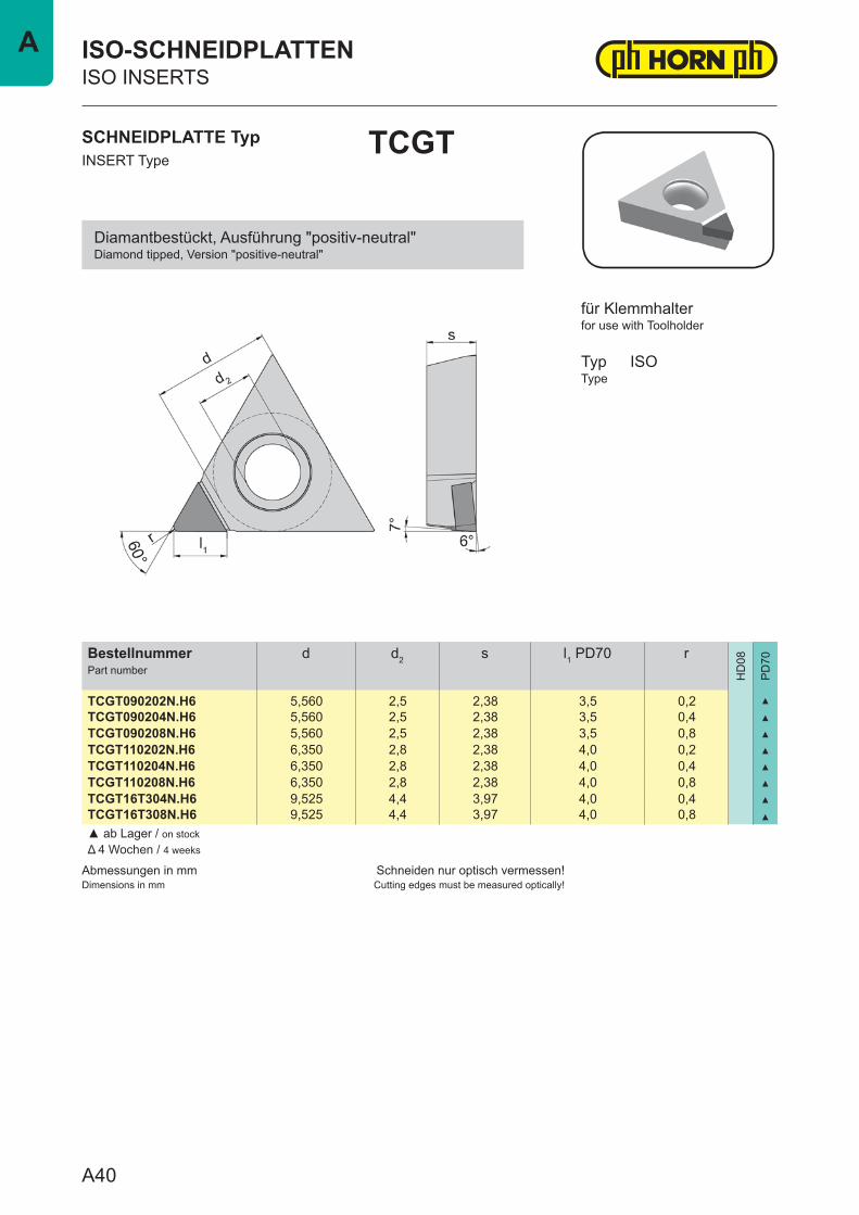
TCGT090202N.H6 5,560 2,5 2,38 3,5 0,2 ▲
TCGT090204N.H6 5,560 2,5 2,38 3,5 0,4 ▲
TCGT090208N.H6 5,560 2,5 2,38 3,5 0,8 ▲
TCGT110202N.H6 6,350 2,8 2,38 4,0 0,2 ▲
TCGT110204N.H6 6,350 2,8 2,38 4,0 0,4 ▲
TCGT110208N.H6 6,350 2,8 2,38 4,0 0,8 ▲
TCGT16T304N.H6 9,525 4,4 3,97 4,0 0,4 ▲
TCGT16T308N.H6 9,525 4,4 3,97 4,0 0,8 ▲
▲ ab Lager / on stockΔ 4 Wochen / 4 weeks
SCHNEIDPLATTE TypINSERT Type
TCGT
ISO-SCHNEIDPLATTENISO INSERTS
for use with Toolholder
TypType
ISO
für Klemmhalter
Diamantbestückt, Ausführung "positiv-neutral"Diamond tipped, Version "positive-neutral"
A40
A
Abmessungen in mmDimensions in mm
Schneiden nur optisch vermessen!Cutting edges must be measured optically!
BestellnummerPart number
d d2 s r
HD
08
PD
70
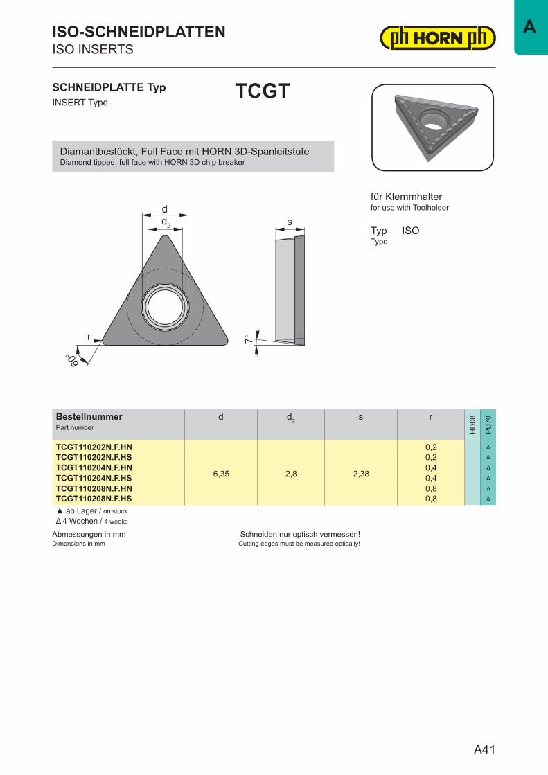
TCGT110202N.F.HN
6,35 2,8 2,38
0,2 Δ
TCGT110202N.F.HS 0,2 Δ
TCGT110204N.F.HN 0,4 Δ
TCGT110204N.F.HS 0,4 Δ
TCGT110208N.F.HN 0,8 Δ
TCGT110208N.F.HS 0,8 Δ
▲ ab Lager / on stockΔ 4 Wochen / 4 weeks
SCHNEIDPLATTE TypINSERT Type
TCGT
ISO-SCHNEIDPLATTENISO INSERTS
for use with Toolholder
TypType
ISO
für Klemmhalter
Diamantbestückt, Full Face mit HORN 3D-SpanleitstufeDiamond tipped, full face with HORN 3D chip breaker
A41
A

Abmessungen in mmDimensions in mm
Schneiden nur optisch vermessen!Cutting edges must be measured optically!
BestellnummerPart number
d d2 s l1 PD70 r
HD
08
PD
70
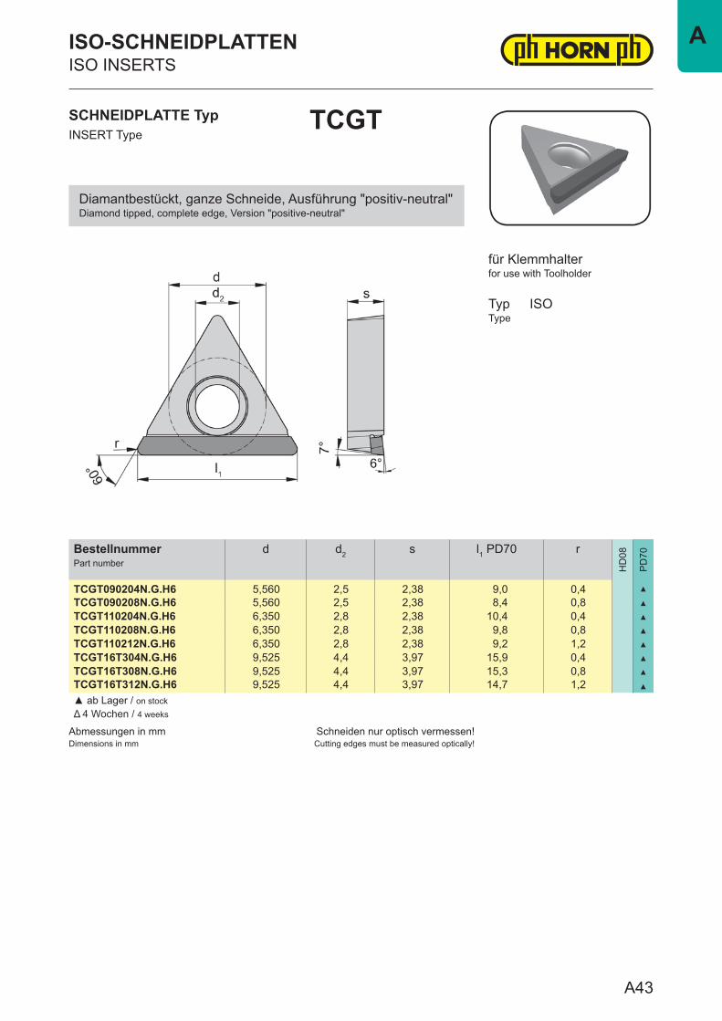
TCGT090204N.G.HN 5,560 2,5 2,38 9,0 0,4 ▲
TCGT090208N.G.HN 5,560 2,5 2,38 8,4 0,8 ▲
TCGT110204N.G.HN 6,350 2,8 2,38 10,4 0,4 ▲
TCGT110208N.G.HN 6,350 2,8 2,38 9,8 0,8 ▲
TCGT110212N.G.HN 6,350 2,8 2,38 9,2 1,2 ▲
TCGT16T304N.G.HN 9,525 4,4 3,97 15,9 0,4 ▲
TCGT16T308N.G.HN 9,525 4,4 3,97 15,3 0,8 ▲
TCGT16T312N.G.HN 9,525 4,4 3,97 14,7 1,2 ▲
▲ ab Lager / on stockΔ 4 Wochen / 4 weeks
SCHNEIDPLATTE TypINSERT Type
TCGT
ISO-SCHNEIDPLATTENISO INSERTS
for use with Toolholder
TypType
ISO
für Klemmhalter
Diamantbestückt, ganze Schneide mit HORN 3D-SpanleitstufeDiamond tipped, complete edge with HORN 3D chip breaker
A42
A
Abmessungen in mmDimensions in mm
Schneiden nur optisch vermessen!Cutting edges must be measured optically!
BestellnummerPart number
d d2 s l1 PD70 r
HD
08
PD
70
TCGT090204N.G.H6 5,560 2,5 2,38 9,0 0,4 ▲
TCGT090208N.G.H6 5,560 2,5 2,38 8,4 0,8 ▲
TCGT110204N.G.H6 6,350 2,8 2,38 10,4 0,4 ▲
TCGT110208N.G.H6 6,350 2,8 2,38 9,8 0,8 ▲
TCGT110212N.G.H6 6,350 2,8 2,38 9,2 1,2 ▲
TCGT16T304N.G.H6 9,525 4,4 3,97 15,9 0,4 ▲
TCGT16T308N.G.H6 9,525 4,4 3,97 15,3 0,8 ▲
TCGT16T312N.G.H6 9,525 4,4 3,97 14,7 1,2 ▲
▲ ab Lager / on stockΔ 4 Wochen / 4 weeks
SCHNEIDPLATTE TypINSERT Type
TCGT
ISO-SCHNEIDPLATTENISO INSERTS
for use with Toolholder
TypType
ISO
für Klemmhalter
Diamantbestückt, ganze Schneide, Ausführung "positiv-neutral"Diamond tipped, complete edge, Version "positive-neutral"
A43
A
Abmessungen in mmDimensions in mm
Schneiden nur optisch vermessen!Cutting edges must be measured optically!
BestellnummerPart number
d d2 s l1 PD70 r
HD
08
PD
70
TCGW090202N.H0 5,560 2,5 2,38 3,5 0,2 ▲
TCGW090204N.H0 5,560 2,5 2,38 3,5 0,4 ▲
TCGW090208N.H0 5,560 2,5 2,38 3,5 0,8 ▲
TCGW110202N.H0 6,350 2,8 2,38 4,0 0,2 ▲
TCGW110204N.H0 6,350 2,8 2,38 4,0 0,4 ▲
TCGW110208N.H0 6,350 2,8 2,38 4,0 0,8 ▲
TCGW16T304N.H0 9,525 4,4 3,97 4,0 0,4 ▲
TCGW16T308N.H0 9,525 4,4 3,97 4,0 0,8 ▲
TCGW16T312N.H0 9,525 4,4 3,97 4,0 1,2 ▲
▲ ab Lager / on stockΔ 4 Wochen / 4 weeks
SCHNEIDPLATTE TypINSERT Type
TCGW
ISO-SCHNEIDPLATTENISO INSERTS
for use with Toolholder
TypType
ISO
für Klemmhalter
Diamantbestückt, Ausführung "neutral"Diamond tipped, Version "neutral"
A44
A
Abmessungen in mmDimensions in mm
Schneiden nur optisch vermessen!Cutting edges must be measured optically!
BestellnummerPart number
d d2 s r
HD
08
PD
70
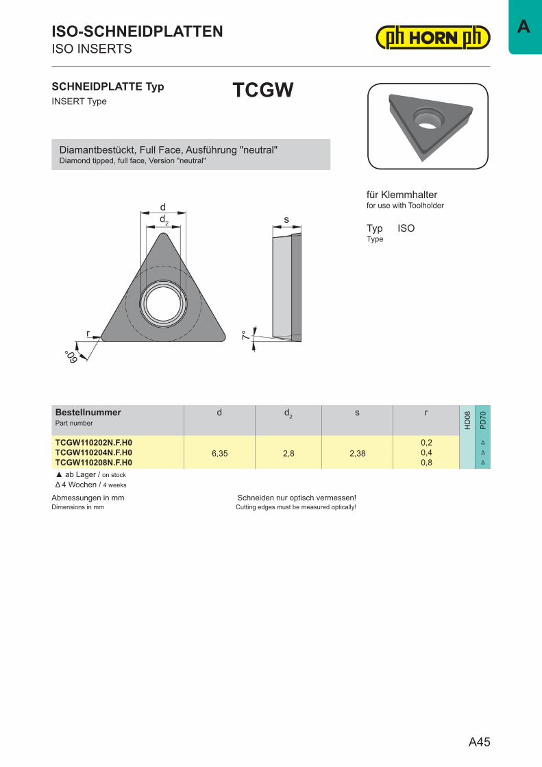
TCGW110202N.F.H06,35 2,8 2,38
0,2 Δ
TCGW110204N.F.H0 0,4 Δ
TCGW110208N.F.H0 0,8 Δ
▲ ab Lager / on stockΔ 4 Wochen / 4 weeks
SCHNEIDPLATTE TypINSERT Type
TCGW
ISO-SCHNEIDPLATTENISO INSERTS
for use with Toolholder
TypType
ISO
für Klemmhalter
Diamantbestückt, Full Face, Ausführung "neutral"Diamond tipped, full face, Version "neutral"
A45
A
Abmessungen in mmDimensions in mm
Schneiden nur optisch vermessen!Cutting edges must be measured optically!
BestellnummerPart number
d d2 s l1 PD70 r
HD
08
PD
70
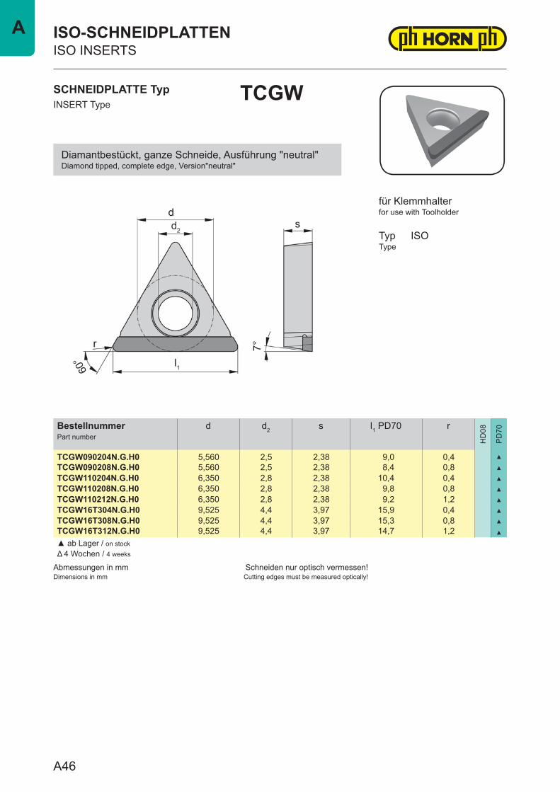
TCGW090204N.G.H0 5,560 2,5 2,38 9,0 0,4 ▲
TCGW090208N.G.H0 5,560 2,5 2,38 8,4 0,8 ▲
TCGW110204N.G.H0 6,350 2,8 2,38 10,4 0,4 ▲
TCGW110208N.G.H0 6,350 2,8 2,38 9,8 0,8 ▲
TCGW110212N.G.H0 6,350 2,8 2,38 9,2 1,2 ▲
TCGW16T304N.G.H0 9,525 4,4 3,97 15,9 0,4 ▲
TCGW16T308N.G.H0 9,525 4,4 3,97 15,3 0,8 ▲
TCGW16T312N.G.H0 9,525 4,4 3,97 14,7 1,2 ▲
▲ ab Lager / on stockΔ 4 Wochen / 4 weeks
SCHNEIDPLATTE TypINSERT Type
TCGW
ISO-SCHNEIDPLATTENISO INSERTS
for use with Toolholder
TypType
ISO
für Klemmhalter
Diamantbestückt, ganze Schneide, Ausführung "neutral"Diamond tipped, complete edge, Version"neutral"
A46
A
Abmessungen in mmDimensions in mm
Schneiden nur optisch vermessen!Cutting edges must be measured optically!
BestellnummerPart number
d d2 s l1 PD70 r
HD
08
PD
70
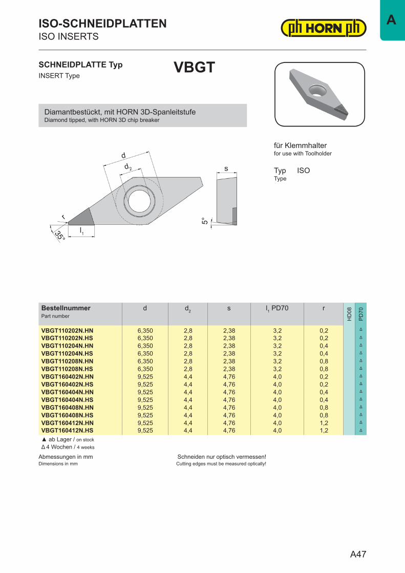
VBGT110202N.HN 6,350 2,8 2,38 3,2 0,2 Δ
VBGT110202N.HS 6,350 2,8 2,38 3,2 0,2 Δ
VBGT110204N.HN 6,350 2,8 2,38 3,2 0,4 Δ
VBGT110204N.HS 6,350 2,8 2,38 3,2 0,4 Δ
VBGT110208N.HN 6,350 2,8 2,38 3,2 0,8 Δ
VBGT110208N.HS 6,350 2,8 2,38 3,2 0,8 Δ
VBGT160402N.HN 9,525 4,4 4,76 4,0 0,2 Δ
VBGT160402N.HS 9,525 4,4 4,76 4,0 0,2 Δ
VBGT160404N.HN 9,525 4,4 4,76 4,0 0,4 Δ
VBGT160404N.HS 9,525 4,4 4,76 4,0 0,4 Δ
VBGT160408N.HN 9,525 4,4 4,76 4,0 0,8 Δ
VBGT160408N.HS 9,525 4,4 4,76 4,0 0,8 Δ
VBGT160412N.HN 9,525 4,4 4,76 4,0 1,2 Δ
VBGT160412N.HS 9,525 4,4 4,76 4,0 1,2 Δ
▲ ab Lager / on stockΔ 4 Wochen / 4 weeks
SCHNEIDPLATTE TypINSERT Type
VBGT
ISO-SCHNEIDPLATTENISO INSERTS
for use with Toolholder
TypType
ISO
für Klemmhalter
Diamantbestückt, mit HORN 3D-SpanleitstufeDiamond tipped, with HORN 3D chip breaker
A47
A
Abmessungen in mmDimensions in mm
Schneiden nur optisch vermessen!Cutting edges must be measured optically!
BestellnummerPart number
d d2 s l1 PD70 r
HD
08
PD
70
VBGW110202N.H0 6,350 2,8 2,38 3,7 0,2 Δ
VBGW110204N.H0 6,350 2,8 2,38 3,7 0,4 Δ
VBGW110208N.H0 6,350 2,8 2,38 3,7 0,8 Δ
VBGW160402N.H0 9,525 4,4 4,76 4,5 0,2 Δ
VBGW160404N.H0 9,525 4,4 4,76 4,5 0,4 Δ
VBGW160408N.H0 9,525 4,4 4,76 4,5 0,8 Δ
VBGW160412N.H0 9,525 4,4 4,76 4,5 1,2 Δ
▲ ab Lager / on stockΔ 4 Wochen / 4 weeks
SCHNEIDPLATTE TypINSERT Type
VBGW
ISO-SCHNEIDPLATTENISO INSERTS
for use with Toolholder
TypType
ISO
für Klemmhalter
Diamantbestückt, Ausführung "neutral"Diamond tipped, Version "neutral"
A48
A
Abmessungen in mmDimensions in mm
Schneiden nur optisch vermessen!Cutting edges must be measured optically!
BestellnummerPart number
d d2 s l1 HD08 l1 PD70 r
HD
08
PD
70
VCGT070201N.HS 3,970 2,25 2,38 2,5 3,2 0,1 ▲ ▲
VCGT070202N.HN 3,970 2,25 2,38 2,5 3,2 0,2 ▲ ▲
VCGT070202N.HS 3,970 2,25 2,38 2,5 3,2 0,2 ▲ ▲
VCGT070204N.HN 3,970 2,25 2,38 2,5 3,2 0,4 ▲ ▲
VCGT070204N.HS 3,970 2,25 2,38 2,5 3,2 0,4 ▲ ▲
VCGT070208N.HN 3,970 2,25 2,38 2,5 - 0,8 ▲
VCGT070208N.HS 3,970 2,25 2,38 2,5 - 0,8 ▲
VCGT110301N.HS 6,350 2,80 3,18 2,5 3,2 0,1 ▲ ▲
VCGT110302N.HN 6,350 2,80 3,18 2,5 3,2 0,2 ▲ ▲
VCGT110302N.HS 6,350 2,80 3,18 2,5 3,2 0,2 ▲ ▲
VCGT110304N.HN 6,350 2,80 3,18 2,5 3,2 0,4 ▲ ▲
VCGT110304N.HS 6,350 2,80 3,18 2,5 3,2 0,4 ▲ ▲
VCGT110308N.HN 6,350 2,80 3,18 2,5 3,2 0,8 ▲ ▲
VCGT110308N.HS 6,350 2,80 3,18 2,5 3,2 0,8 ▲ ▲
VCGT130301N.HS 7,938 3,40 3,18 - 4,0 0,1 ▲
VCGT130302N.HN 7,938 3,40 3,18 - 4,0 0,2 ▲
VCGT130302N.HS 7,938 3,40 3,18 - 4,0 0,2 ▲
VCGT130304N.HN 7,938 3,40 3,18 - 4,0 0,4 ▲
VCGT130304N.HS 7,938 3,40 3,18 - 4,0 0,4 ▲
VCGT130308N.HN 7,938 3,40 3,18 - 4,0 0,8 ▲
VCGT130308N.HS 7,938 3,40 3,18 - 4,0 0,8 ▲
VCGT160401N.HS 9,525 4,40 4,76 2,5 4,0 0,1 ▲ ▲
VCGT160402N.HN 9,525 4,40 4,76 2,5 4,0 0,2 ▲ ▲
VCGT160402N.HS 9,525 4,40 4,76 2,5 4,0 0,2 ▲ ▲
VCGT160404N.HN 9,525 4,40 4,76 2,5 4,0 0,4 ▲ ▲
VCGT160404N.HS 9,525 4,40 4,76 2,5 4,0 0,4 ▲ ▲
VCGT160408N.HN 9,525 4,40 4,76 2,5 4,0 0,8 ▲ ▲
VCGT160408N.HS 9,525 4,40 4,76 2,5 4,0 0,8 ▲ ▲
VCGT160412N.HN 9,525 4,40 4,76 2,5 4,0 1,2 ▲ ▲
SCHNEIDPLATTE TypINSERT Type
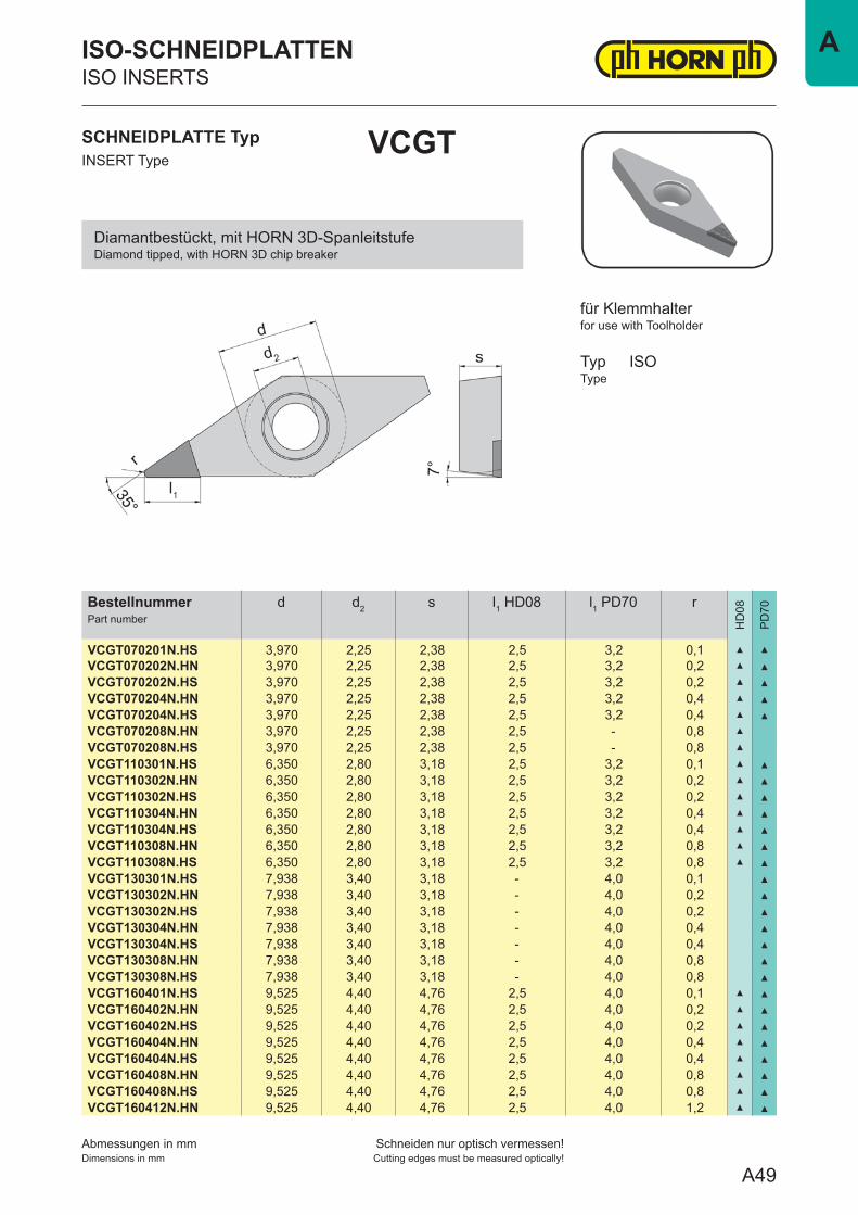
VCGT
ISO-SCHNEIDPLATTENISO INSERTS
for use with Toolholder
TypType
ISO
für Klemmhalter
Diamantbestückt, mit HORN 3D-SpanleitstufeDiamond tipped, with HORN 3D chip breaker
A49
A
Abmessungen in mmDimensions in mm
Schneiden nur optisch vermessen!Cutting edges must be measured optically!
BestellnummerPart number
d d2 s l1 HD08 l1 PD70 r
HD
08
PD
70
VCGT070201N.H6 3,970 2,25 2,38 - 3,7 0,1 ▲
VCGT070202N.H6 3,970 2,25 2,38 - 3,7 0,2 ▲
VCGT070204N.H6 3,970 2,25 2,38 - 3,7 0,4 ▲
VCGT110301N.H6 6,350 2,80 3,18 3 3,7 0,1 ▲ ▲
VCGT110302N.H6 6,350 2,80 3,18 3 3,7 0,2 ▲ ▲
VCGT110304N.H6 6,350 2,80 3,18 3 3,7 0,4 ▲ ▲
VCGT110308N.H6 6,350 2,80 3,18 3 3,7 0,8 ▲ ▲
VCGT130301N.H6 7,938 3,40 3,18 - 4,7 0,1 ▲
VCGT130302N.H6 7,938 3,40 3,18 - 4,7 0,2 ▲
VCGT130304N.H6 7,938 3,40 3,18 - 4,7 0,4 ▲
VCGT130308N.H6 7,938 3,40 3,18 - 4,7 0,8 ▲
VCGT160401N.H6 9,525 4,40 4,76 3 4,5 0,1 ▲ ▲
VCGT160402N.H6 9,525 4,40 4,76 3 4,5 0,2 ▲ ▲
VCGT160404N.H6 9,525 4,40 4,76 3 4,5 0,4 ▲ ▲
VCGT160408N.H6 9,525 4,40 4,76 3 4,5 0,8 ▲ ▲
VCGT160412N.H6 9,525 4,40 4,76 3 4,5 1,2 ▲ ▲
▲ ab Lager / on stockΔ 4 Wochen / 4 weeks
SCHNEIDPLATTE TypINSERT Type
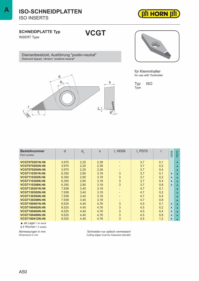
VCGT
ISO-SCHNEIDPLATTENISO INSERTS
for use with Toolholder
TypType
ISO
für Klemmhalter
Diamantbestückt, Ausführung "positiv-neutral"Diamond tipped, Version "positive-neutral"
A50
A
Abmessungen in mmDimensions in mm
Schneiden nur optisch vermessen!Cutting edges must be measured optically!
BestellnummerPart number
d d2 s l1 HD08 l1 PD70 r
HD
08
PD
70
VCGW070201N.H0 3,970 2,25 2,38 - 3,7 0,1 ▲
VCGW070202N.H0 3,970 2,25 2,38 - 3,7 0,2 ▲
VCGW070204N.H0 3,970 2,25 2,38 - 3,7 0,4 ▲
VCGW110301N.H0 6,350 2,80 3,18 3 3,7 0,1 Δ ▲
VCGW110302N.H0 6,350 2,80 3,18 3 3,7 0,2 ▲ ▲
VCGW110304N.H0 6,350 2,80 3,18 3 3,7 0,4 ▲ ▲
VCGW110308N.H0 6,350 2,80 3,18 3 3,7 0,8 ▲ ▲
VCGW130301N.H0 7,938 3,40 3,18 - 4,5 0,1 ▲
VCGW130302N.H0 7,938 3,40 3,18 - 4,5 0,2 ▲
VCGW130304N.H0 7,938 3,40 3,18 - 4,5 0,4 ▲
VCGW130308N.H0 7,938 3,40 3,18 - 4,5 0,8 ▲
VCGW160401N.H0 9,525 4,40 4,76 3 4,5 0,1 Δ ▲
VCGW160402N.H0 9,525 4,40 4,76 3 4,5 0,2 ▲ ▲
VCGW160404N.H0 9,525 4,40 4,76 3 4,5 0,4 ▲ ▲
VCGW160408N.H0 9,525 4,40 4,76 3 4,5 0,8 ▲ ▲
VCGW160412N.H0 9,525 4,40 4,76 3 4,5 1,2 Δ ▲
▲ ab Lager / on stockΔ 4 Wochen / 4 weeks
SCHNEIDPLATTE TypINSERT Type
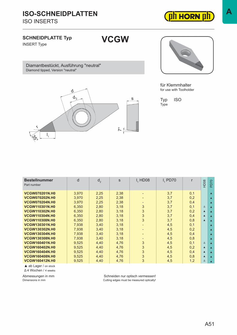
VCGW
ISO-SCHNEIDPLATTENISO INSERTS
for use with Toolholder
TypType
ISO
für Klemmhalter
Diamantbestückt, Ausführung "neutral"Diamond tipped, Version "neutral"
A51
A
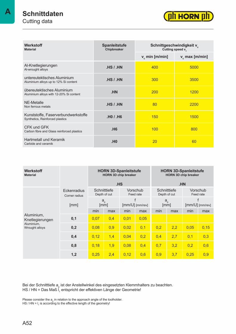
WerkstoffMaterial
SpanleitstufeChipbreaker
Schnittgeschwindigkeit vcCutting speed vc
vc min [m/min] vc max [m/min]
Al-KnetlegierungenAl-wrought alloys .HS / .HN 400 5000
untereutektisches AluminiumAluminium alloys up to 12% Si content .HS / .HN 300 3500
übereutektisches AluminiumAluminium alloys with 12-20% Si content .HN 200 1200
NE-MetalleNon ferrous metals .HS / .HN 80 2200
Kunststoffe, FaserverbundwerkstoffeSynthetics, Reinforced plastics .H0 / .H6 150 1500
CFK und GFKCarbon fibre and Glass reinforced plastics .H6 100 800
Hartmetall und KeramikCarbide and ceramik .H0 20 60
WerkstoffMaterial
EckenradiusCorner radius
[mm]
HORN 3D-SpanleitstufeHORN 3D chip breaker
.HS
HORN 3D-SpanleitstufeHORN 3D chip breaker
.HN
Aluminium, KnetlegierungenAluminium, Wrought alloys
SchnitttiefeDepth of cut
VorschubFeed rate
SchnitttiefeDepth of cut
VorschubFeed rate
ap[mm]
f[mm/U] [mm/rev]
ap[mm]
f[mm/U] [mm/rev]
min max min max min max min max
0,1 0,07 0,4 0,01 0,05
0,2 0,08 0,9 0,02 0,1 0,2 2,2 0,05 0,15
0,4 0,12 1,4 0,04 0,2 0,4 2,7 0,1 0,3
0,8 0,18 1,9 0,08 0,4 0,7 3,2 0,2 0,6
1,2 0,25 2,4 0,12 0,6 0,9 3,7 0,25 0,9
SchnittdatenCutting data
Bei der Schnitttiefe ap ist der Anstellwinkel des eingesetzten Klemmhalters zu beachten.HS / HN = Das Maß l1 entspricht der effektiven Länge der Geometrie!
Please consider the ap in relation to the approach angle of the toolholder.HS / HN = l1 is according to the effective length of the geometry!
A52
A
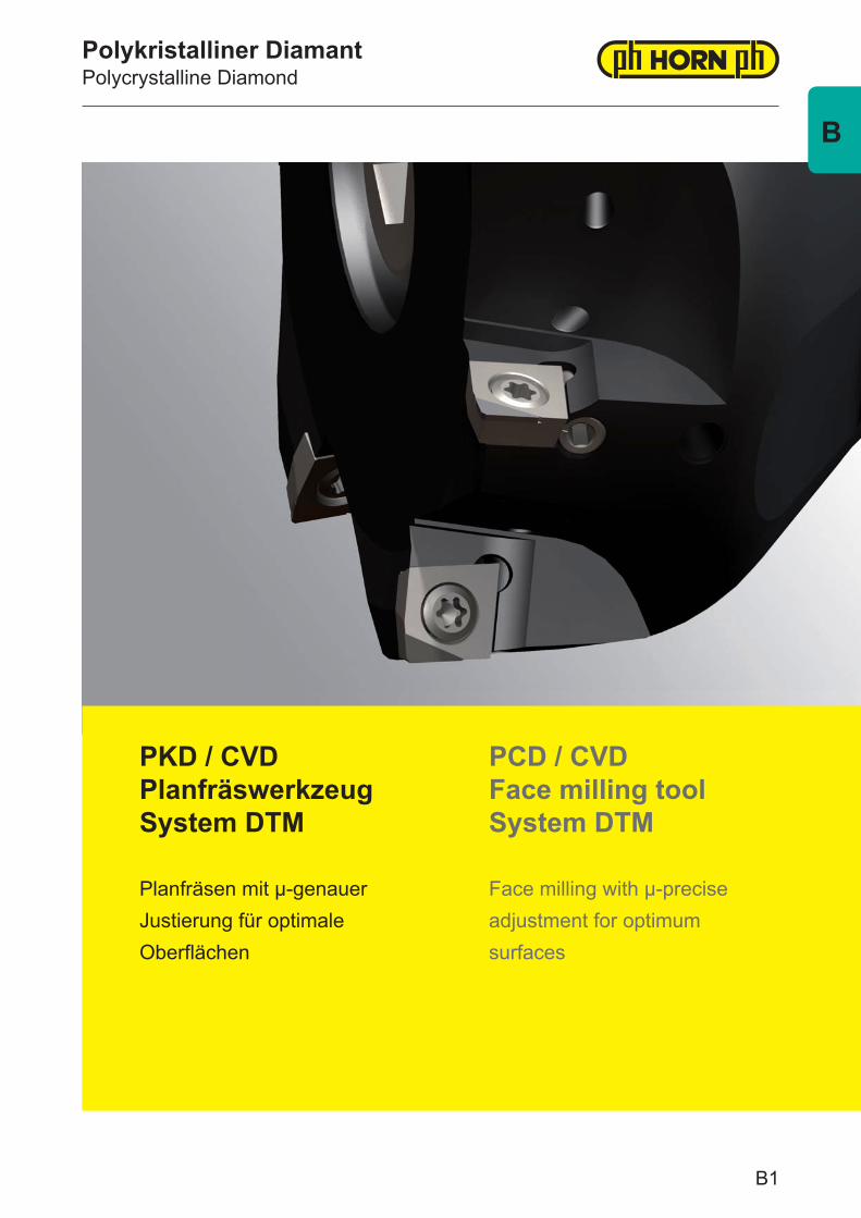
Polykristalliner DiamantPolycrystalline Diamond
PKD / CVD Planfräswerkzeug System DTM
Planfräsen mit μ-genauerJustierung für optimaleOberflächen
PCD / CVD Face milling tool System DTM
Face milling with μ-precise adjustment for optimum surfaces
B1
B
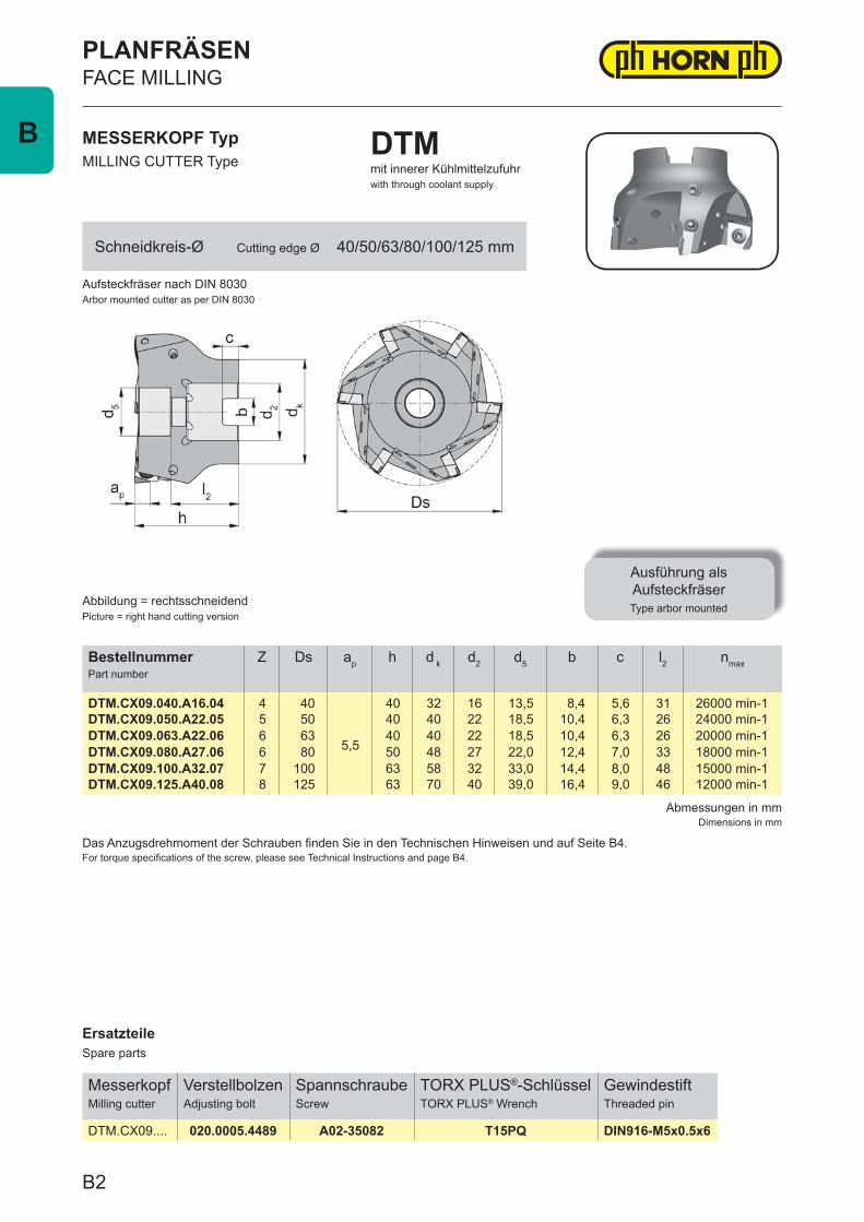
ErsatzteileSpare parts
MesserkopfMilling cutter
VerstellbolzenAdjusting bolt
SpannschraubeScrew
TORX PLUS®-SchlüsselTORX PLUS® Wrench
GewindestiftThreaded pin
DTM.CX09.... 020.0005.4489 A02-35082 T15PQ DIN916-M5x0.5x6
Abmessungen in mmDimensions in mm
Das Anzugsdrehmoment der Schrauben fi nden Sie in den Technischen Hinweisen und auf Seite B4.For torque specifi cations of the screw, please see Technical Instructions and page B4.
BestellnummerPart number
Z Ds ap h d k d2 d5 b c l2 nmax
DTM.CX09.040.A16.04 4 40
5,5
40 32 16 13,5 8,4 5,6 31 26000 min-1DTM.CX09.050.A22.05 5 50 40 40 22 18,5 10,4 6,3 26 24000 min-1DTM.CX09.063.A22.06 6 63 40 40 22 18,5 10,4 6,3 26 20000 min-1DTM.CX09.080.A27.06 6 80 50 48 27 22,0 12,4 7,0 33 18000 min-1DTM.CX09.100.A32.07 7 100 63 58 32 33,0 14,4 8,0 48 15000 min-1DTM.CX09.125.A40.08 8 125 63 70 40 39,0 16,4 9,0 46 12000 min-1
Aufsteckfräser nach DIN 8030Arbor mounted cutter as per DIN 8030
MESSERKOPF TypMILLING CUTTER Type
DTMmit innerer Kühlmittelzufuhrwith through coolant supply
Abbildung = rechtsschneidendPicture = right hand cutting version
Ausführung alsAufsteckfräserType arbor mounted
PLANFRÄSENFACE MILLING
Schneidkreis-Ø Cutting edge Ø 40/50/63/80/100/125 mm
B2
B
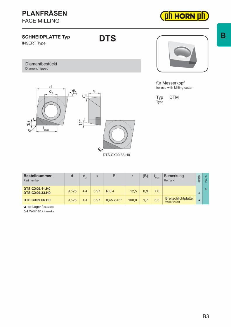
BestellnummerPart number
d d2 s E r (B) tmax BemerkungRemark H
D08
PD
75
DTS.CX09.11.H0 9,525 4,4 3,97 R 0,4 12,5 0,9 7,0
▲
DTS.CX09.33.H0 ▲
DTS.CX09.66.H0 9,525 4,4 3,97 0,45 x 45° 100,0 1,7 5,5 BreitschlichtplatteWiper insert
▲
▲ ab Lager / on stockΔ 4 Wochen / 4 weeks
SCHNEIDPLATTE TypINSERT Type
DTS
PLANFRÄSENFACE MILLING
for use with Milling cutter
TypType
DTM
für Messerkopf
DiamantbestücktDiamond tipped
B3
B
WerkstoffMaterial
Schneid-stoffCutting material
vc (m/min) fZ ap (mm)
schruppenroughing
schlichtenfinishing
schruppenroughing
schlichtenfinishing
schruppenroughing
schlichtenfinishing
Alu
min
ium
legi
erun
gA
lum
iniu
m a
lloys
Si <
12% HD08 500 - 3500 500 - 5000
0,05 - 0,25
0,02 - 0,10
3,50,5
PD75 400 - 2500 400 - 3500 5,5
Si >
12% HD08 300 - 1200 400 - 2000
0,03 - 0,202,5
0,3PD75 200 - 800 200 - 1000 3,5
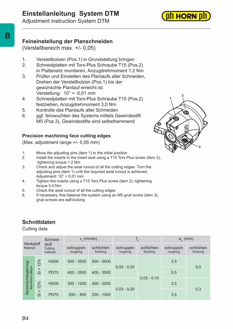
Feineinstellung der Planschneiden(Verstellbereich max. +/- 0,05)
1. Verstellbolzen (Pos.1) in Grundstellung bringen2. Schneidplatten mit Torx-Plus Schraube T15 (Pos.2) in Plattensitz montieren, Anzugdrehmoment 1,2 Nm3. Prüfen und Einstellen des Planlaufs aller Schneiden, Drehen der Verstellbolzen (Pos.1) bis der gewünschte Planlauf erreicht ist. Verstellung: 10° = 0,01 mm4. Schneidplatten mit Torx-Plus Schraube T15 (Pos.2) festziehen, Anzugdrehmoment 3,0 Nm5. Kontrolle des Planlaufs aller Schneiden6. ggf. feinwuchten des Systems mittels Gewindestift M5 (Pos.3), Gewindestifte sind selbsthemmend
Einstellanleitung System DTMAdjustment instruction System DTM
Precision machining face cutting edges(Max. adjustment range +/- 0,05 mm)
1. Move the adjusting pins (item 1) to the initial position2. Install the inserts in the insert seat using a T15 Torx Plus screw (item 2), tightening torque 1.2 Nm3. Check and adjust the axial runout of all the cutting edges. Turn the adjusting pins (item 1) until the required axial runout is achieved. Adjustment: 10° = 0.01 mm4. Tighten the inserts using a T15 Torx Plus screw (item 2), tightening torque 3.0 Nm5. Check the axial runout of all the cutting edges6. If necessary, fine balance the system using an M5 grub screw (item 3), grub screws are self-locking
SchnittdatenCutting data
B4
B
Polykristalliner DiamantPolycrystalline Diamond
CVD-D Fräswerkzeug System DS
CVD-D milling tool System DS
C1
C
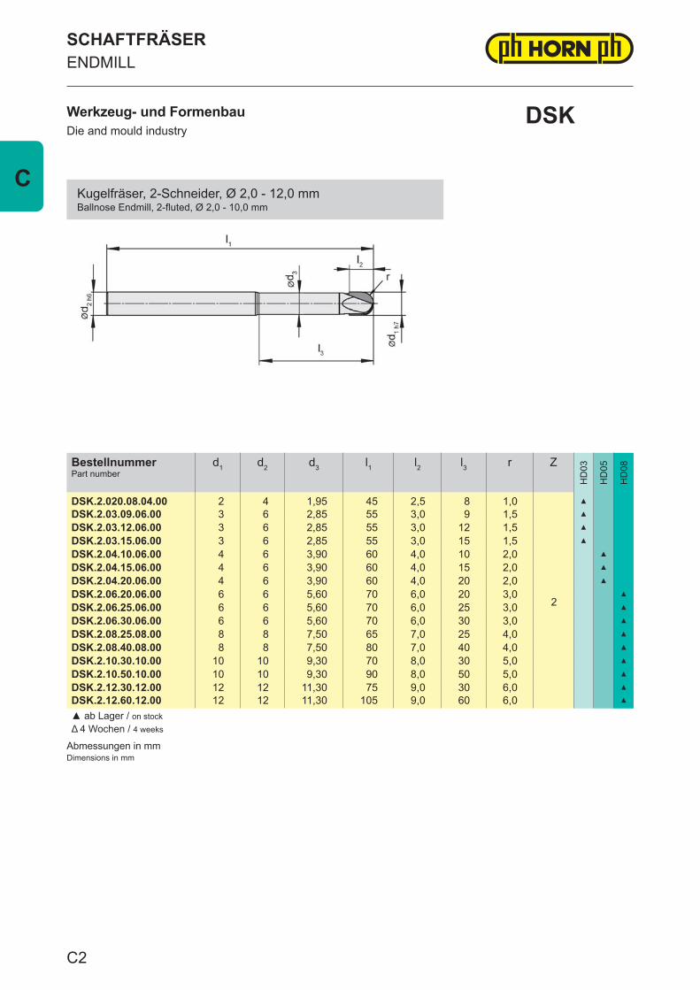
Abmessungen in mmDimensions in mm
BestellnummerPart number
d1 d2 d3 l1 l2 l3 r Z
HD
03
HD
05
HD
08
DSK.2.020.08.04.00 2 4 1,95 45 2,5 8 1,0
2
▲
DSK.2.03.09.06.00 3 6 2,85 55 3,0 9 1,5 ▲
DSK.2.03.12.06.00 3 6 2,85 55 3,0 12 1,5 ▲
DSK.2.03.15.06.00 3 6 2,85 55 3,0 15 1,5 ▲
DSK.2.04.10.06.00 4 6 3,90 60 4,0 10 2,0 ▲
DSK.2.04.15.06.00 4 6 3,90 60 4,0 15 2,0 ▲
DSK.2.04.20.06.00 4 6 3,90 60 4,0 20 2,0 ▲
DSK.2.06.20.06.00 6 6 5,60 70 6,0 20 3,0 ▲
DSK.2.06.25.06.00 6 6 5,60 70 6,0 25 3,0 ▲
DSK.2.06.30.06.00 6 6 5,60 70 6,0 30 3,0 ▲
DSK.2.08.25.08.00 8 8 7,50 65 7,0 25 4,0 ▲
DSK.2.08.40.08.00 8 8 7,50 80 7,0 40 4,0 ▲
DSK.2.10.30.10.00 10 10 9,30 70 8,0 30 5,0 ▲
DSK.2.10.50.10.00 10 10 9,30 90 8,0 50 5,0 ▲
DSK.2.12.30.12.00 12 12 11,30 75 9,0 30 6,0 ▲
DSK.2.12.60.12.00 12 12 11,30 105 9,0 60 6,0 ▲
▲ ab Lager / on stockΔ 4 Wochen / 4 weeks
Werkzeug- und FormenbauDie and mould industry
SCHAFTFRÄSERENDMILL
DSK
Kugelfräser, 2-Schneider, Ø 2,0 - 12,0 mmBallnose Endmill, 2-fluted, Ø 2,0 - 10,0 mm
C2
C
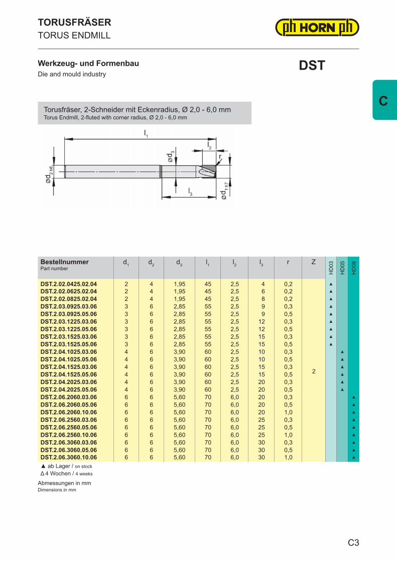
Abmessungen in mmDimensions in mm
BestellnummerPart number
d1 d2 d3 l1 l2 l3 r Z
HD
03
HD
05
HD
08
DST.2.02.0425.02.04 2 4 1,95 45 2,5 4 0,2
2
▲
DST.2.02.0625.02.04 2 4 1,95 45 2,5 6 0,2 ▲
DST.2.02.0825.02.04 2 4 1,95 45 2,5 8 0,2 ▲
DST.2.03.0925.03.06 3 6 2,85 55 2,5 9 0,3 ▲
DST.2.03.0925.05.06 3 6 2,85 55 2,5 9 0,5 ▲
DST.2.03.1225.03.06 3 6 2,85 55 2,5 12 0,3 ▲
DST.2.03.1225.05.06 3 6 2,85 55 2,5 12 0,5 ▲
DST.2.03.1525.03.06 3 6 2,85 55 2,5 15 0,3 ▲
DST.2.03.1525.05.06 3 6 2,85 55 2,5 15 0,5 ▲
DST.2.04.1025.03.06 4 6 3,90 60 2,5 10 0,3 ▲
DST.2.04.1025.05.06 4 6 3,90 60 2,5 10 0,5 ▲
DST.2.04.1525.03.06 4 6 3,90 60 2,5 15 0,3 ▲
DST.2.04.1525.05.06 4 6 3,90 60 2,5 15 0,5 ▲
DST.2.04.2025.03.06 4 6 3,90 60 2,5 20 0,3 ▲
DST.2.04.2025.05.06 4 6 3,90 60 2,5 20 0,5 ▲
DST.2.06.2060.03.06 6 6 5,60 70 6,0 20 0,3 ▲
DST.2.06.2060.05.06 6 6 5,60 70 6,0 20 0,5 ▲
DST.2.06.2060.10.06 6 6 5,60 70 6,0 20 1,0 ▲
DST.2.06.2560.03.06 6 6 5,60 70 6,0 25 0,3 ▲
DST.2.06.2560.05.06 6 6 5,60 70 6,0 25 0,5 ▲
DST.2.06.2560.10.06 6 6 5,60 70 6,0 25 1,0 ▲
DST.2.06.3060.03.06 6 6 5,60 70 6,0 30 0,3 ▲
DST.2.06.3060.05.06 6 6 5,60 70 6,0 30 0,5 ▲
DST.2.06.3060.10.06 6 6 5,60 70 6,0 30 1,0 ▲
▲ ab Lager / on stockΔ 4 Wochen / 4 weeks
TORUSFRÄSERTORUS ENDMILL
Werkzeug- und FormenbauDie and mould industry
DST
Torusfräser, 2-Schneider mit Eckenradius, Ø 2,0 - 6,0 mmTorus Endmill, 2-fluted with corner radius, Ø 2,0 - 6,0 mm
C3
C
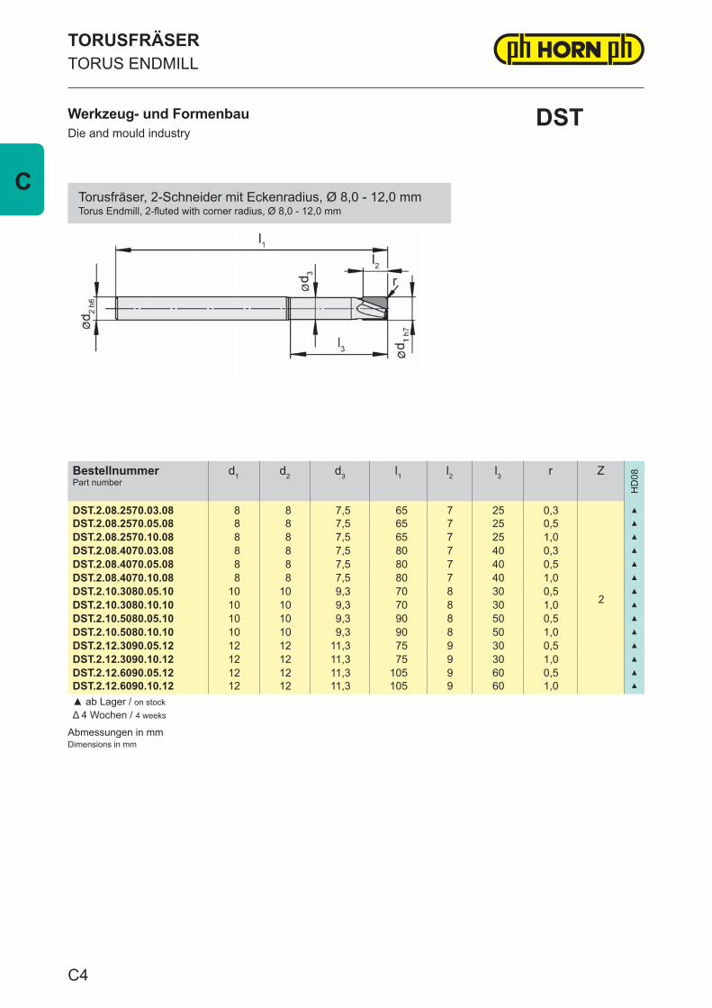
Abmessungen in mmDimensions in mm
BestellnummerPart number
d1 d2 d3 l1 l2 l3 r Z
HD
08
DST.2.08.2570.03.08 8 8 7,5 65 7 25 0,3
2
▲
DST.2.08.2570.05.08 8 8 7,5 65 7 25 0,5 ▲
DST.2.08.2570.10.08 8 8 7,5 65 7 25 1,0 ▲
DST.2.08.4070.03.08 8 8 7,5 80 7 40 0,3 ▲
DST.2.08.4070.05.08 8 8 7,5 80 7 40 0,5 ▲
DST.2.08.4070.10.08 8 8 7,5 80 7 40 1,0 ▲
DST.2.10.3080.05.10 10 10 9,3 70 8 30 0,5 ▲
DST.2.10.3080.10.10 10 10 9,3 70 8 30 1,0 ▲
DST.2.10.5080.05.10 10 10 9,3 90 8 50 0,5 ▲
DST.2.10.5080.10.10 10 10 9,3 90 8 50 1,0 ▲
DST.2.12.3090.05.12 12 12 11,3 75 9 30 0,5 ▲
DST.2.12.3090.10.12 12 12 11,3 75 9 30 1,0 ▲
DST.2.12.6090.05.12 12 12 11,3 105 9 60 0,5 ▲
DST.2.12.6090.10.12 12 12 11,3 105 9 60 1,0 ▲
▲ ab Lager / on stockΔ 4 Wochen / 4 weeks
Werkzeug- und FormenbauDie and mould industry
TORUSFRÄSERTORUS ENDMILL
DST
Torusfräser, 2-Schneider mit Eckenradius, Ø 8,0 - 12,0 mmTorus Endmill, 2-fluted with corner radius, Ø 8,0 - 12,0 mm
C4
C
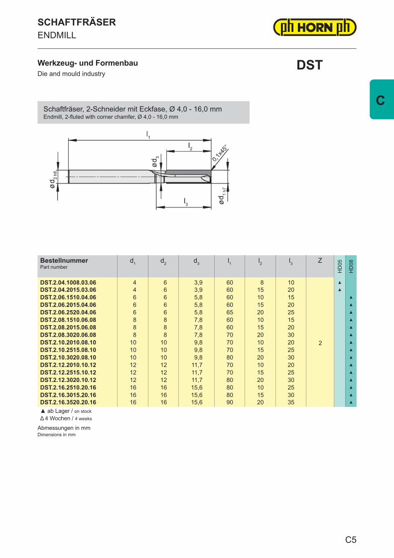
Abmessungen in mmDimensions in mm
BestellnummerPart number
d1 d2 d3 l1 l2 l3 Z
HD
05
HD
08
DST.2.04.1008.03.06 4 6 3,9 60 8 10
2
▲
DST.2.04.2015.03.06 4 6 3,9 60 15 20 ▲
DST.2.06.1510.04.06 6 6 5,8 60 10 15 ▲
DST.2.06.2015.04.06 6 6 5,8 60 15 20 ▲
DST.2.06.2520.04.06 6 6 5,8 65 20 25 ▲
DST.2.08.1510.06.08 8 8 7,8 60 10 15 ▲
DST.2.08.2015.06.08 8 8 7,8 60 15 20 ▲
DST.2.08.3020.06.08 8 8 7,8 70 20 30 ▲
DST.2.10.2010.08.10 10 10 9,8 70 10 20 ▲
DST.2.10.2515.08.10 10 10 9,8 70 15 25 ▲
DST.2.10.3020.08.10 10 10 9,8 80 20 30 ▲
DST.2.12.2010.10.12 12 12 11,7 70 10 20 ▲
DST.2.12.2515.10.12 12 12 11,7 70 15 25 ▲
DST.2.12.3020.10.12 12 12 11,7 80 20 30 ▲
DST.2.16.2510.20.16 16 16 15,6 80 10 25 ▲
DST.2.16.3015.20.16 16 16 15,6 80 15 30 ▲
DST.2.16.3520.20.16 16 16 15,6 90 20 35 ▲
▲ ab Lager / on stockΔ 4 Wochen / 4 weeks
SCHAFTFRÄSERENDMILL
Werkzeug- und FormenbauDie and mould industry
DST
Schaftfräser, 2-Schneider mit Eckfase, Ø 4,0 - 16,0 mmEndmill, 2-fluted with corner chamfer, Ø 4,0 - 16,0 mm
C5
C
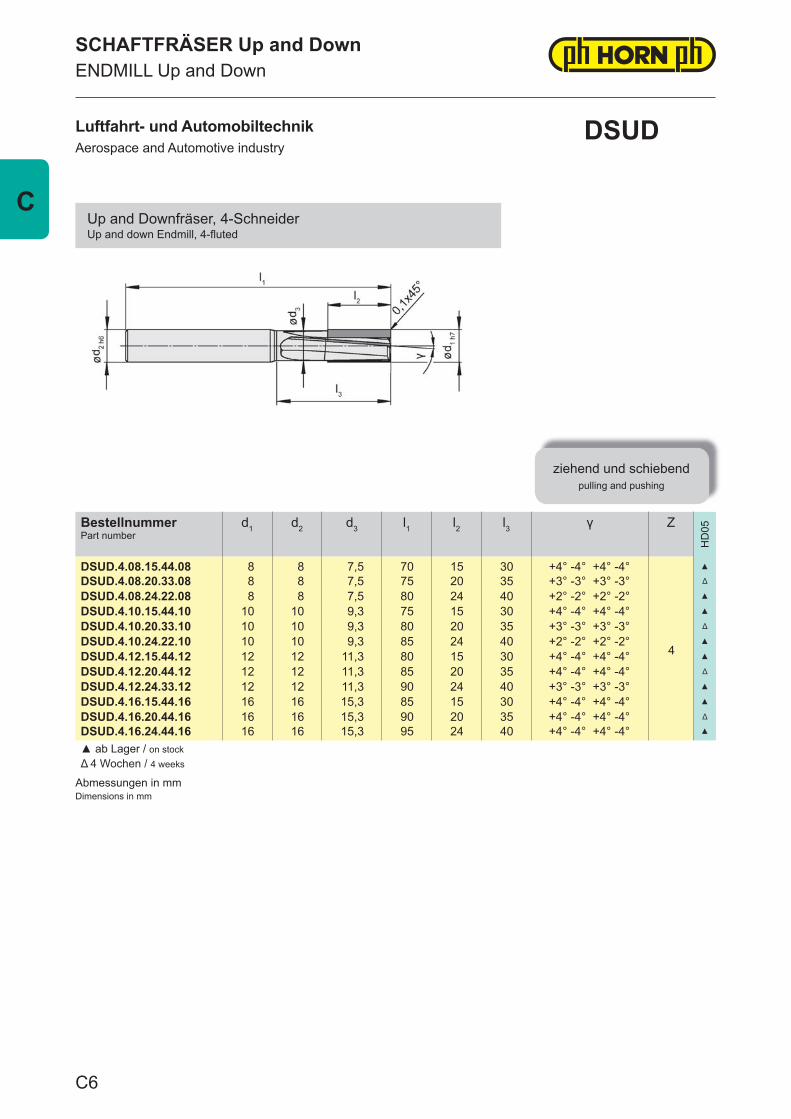
Abmessungen in mmDimensions in mm
BestellnummerPart number
d1 d2 d3 l1 l2 l3 γ Z
HD
05
DSUD.4.08.15.44.08 8 8 7,5 70 15 30 +4° -4° +4° -4°
4
▲
DSUD.4.08.20.33.08 8 8 7,5 75 20 35 +3° -3° +3° -3° Δ
DSUD.4.08.24.22.08 8 8 7,5 80 24 40 +2° -2° +2° -2° ▲
DSUD.4.10.15.44.10 10 10 9,3 75 15 30 +4° -4° +4° -4° ▲
DSUD.4.10.20.33.10 10 10 9,3 80 20 35 +3° -3° +3° -3° Δ
DSUD.4.10.24.22.10 10 10 9,3 85 24 40 +2° -2° +2° -2° ▲
DSUD.4.12.15.44.12 12 12 11,3 80 15 30 +4° -4° +4° -4° ▲
DSUD.4.12.20.44.12 12 12 11,3 85 20 35 +4° -4° +4° -4° Δ
DSUD.4.12.24.33.12 12 12 11,3 90 24 40 +3° -3° +3° -3° ▲
DSUD.4.16.15.44.16 16 16 15,3 85 15 30 +4° -4° +4° -4° ▲
DSUD.4.16.20.44.16 16 16 15,3 90 20 35 +4° -4° +4° -4° Δ
DSUD.4.16.24.44.16 16 16 15,3 95 24 40 +4° -4° +4° -4° ▲
▲ ab Lager / on stockΔ 4 Wochen / 4 weeks
Luftfahrt- und AutomobiltechnikAerospace and Automotive industry
SCHAFTFRÄSER Up and DownENDMILL Up and Down
ziehend und schiebendpulling and pushing
DSUD
Up and Downfräser, 4-SchneiderUp and down Endmill, 4-fl uted
C6
C
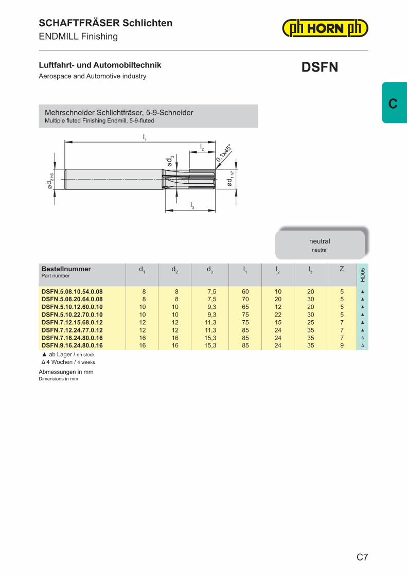
Abmessungen in mmDimensions in mm
BestellnummerPart number
d1 d2 d3 l1 l2 l3 Z
HD
05
DSFN.5.08.10.54.0.08 8 8 7,5 60 10 20 5 ▲
DSFN.5.08.20.64.0.08 8 8 7,5 70 20 30 5 ▲
DSFN.5.10.12.60.0.10 10 10 9,3 65 12 20 5 ▲
DSFN.5.10.22.70.0.10 10 10 9,3 75 22 30 5 ▲
DSFN.7.12.15.68.0.12 12 12 11,3 75 15 25 7 ▲
DSFN.7.12.24.77.0.12 12 12 11,3 85 24 35 7 ▲
DSFN.7.16.24.80.0.16 16 16 15,3 85 24 35 7 Δ
DSFN.9.16.24.80.0.16 16 16 15,3 85 24 35 9 Δ
▲ ab Lager / on stockΔ 4 Wochen / 4 weeks
SCHAFTFRÄSER SchlichtenENDMILL Finishing
neutralneutral
Luftfahrt- und AutomobiltechnikAerospace and Automotive industry
DSFN
Mehrschneider Schlichtfräser, 5-9-SchneiderMultiple fl uted Finishing Endmill, 5-9-fl uted
C7
C
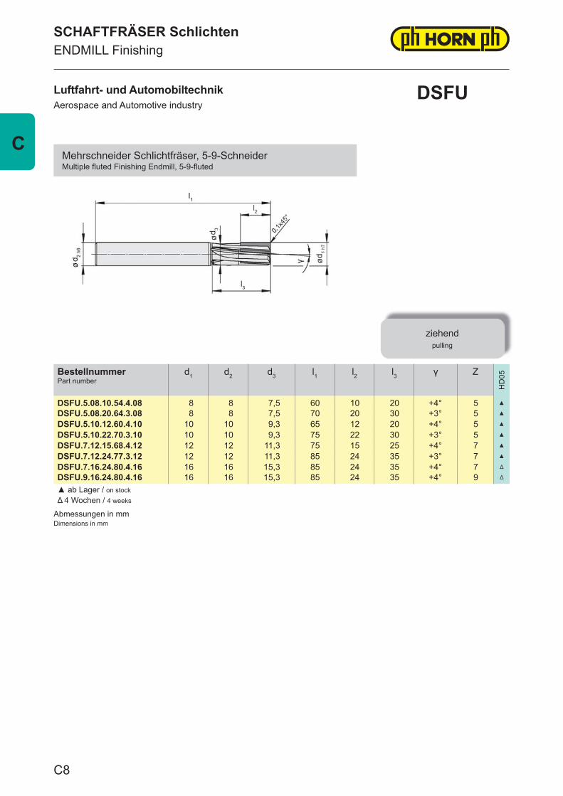
Abmessungen in mmDimensions in mm
BestellnummerPart number
d1 d2 d3 l1 l2 l3 γ Z
HD
05
DSFU.5.08.10.54.4.08 8 8 7,5 60 10 20 +4° 5 ▲
DSFU.5.08.20.64.3.08 8 8 7,5 70 20 30 +3° 5 ▲
DSFU.5.10.12.60.4.10 10 10 9,3 65 12 20 +4° 5 ▲
DSFU.5.10.22.70.3.10 10 10 9,3 75 22 30 +3° 5 ▲
DSFU.7.12.15.68.4.12 12 12 11,3 75 15 25 +4° 7 ▲
DSFU.7.12.24.77.3.12 12 12 11,3 85 24 35 +3° 7 ▲
DSFU.7.16.24.80.4.16 16 16 15,3 85 24 35 +4° 7 Δ
DSFU.9.16.24.80.4.16 16 16 15,3 85 24 35 +4° 9 Δ
▲ ab Lager / on stockΔ 4 Wochen / 4 weeks
Luftfahrt- und AutomobiltechnikAerospace and Automotive industry
SCHAFTFRÄSER SchlichtenENDMILL Finishing
ziehendpulling
DSFU
Mehrschneider Schlichtfräser, 5-9-SchneiderMultiple fl uted Finishing Endmill, 5-9-fl uted
C8
C
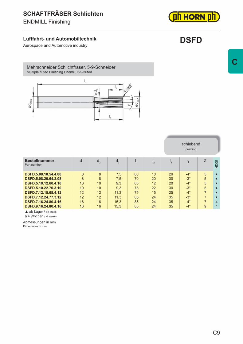
Abmessungen in mmDimensions in mm
BestellnummerPart number
d1 d2 d3 l1 l2 l3 γ Z
HD
05
DSFD.5.08.10.54.4.08 8 8 7,5 60 10 20 -4° 5 ▲
DSFD.5.08.20.64.3.08 8 8 7,5 70 20 30 -3° 5 ▲
DSFD.5.10.12.60.4.10 10 10 9,3 65 12 20 -4° 5 ▲
DSFD.5.10.22.70.3.10 10 10 9,3 75 22 30 -3° 5 ▲
DSFD.7.12.15.68.4.12 12 12 11,3 75 15 25 -4° 7 ▲
DSFD.7.12.24.77.3.12 12 12 11,3 85 24 35 -3° 7 ▲
DSFD.7.16.24.80.4.16 16 16 15,3 85 24 35 -4° 7 Δ
DSFD.9.16.24.80.4.16 16 16 15,3 85 24 35 -4° 9 Δ
▲ ab Lager / on stockΔ 4 Wochen / 4 weeks
SCHAFTFRÄSER SchlichtenENDMILL Finishing
schiebendpushing
Luftfahrt- und AutomobiltechnikAerospace and Automotive industry
DSFD
Mehrschneider Schlichtfräser, 5-9-SchneiderMultiple fl uted Finishing Endmill, 5-9-fl uted
C9
C
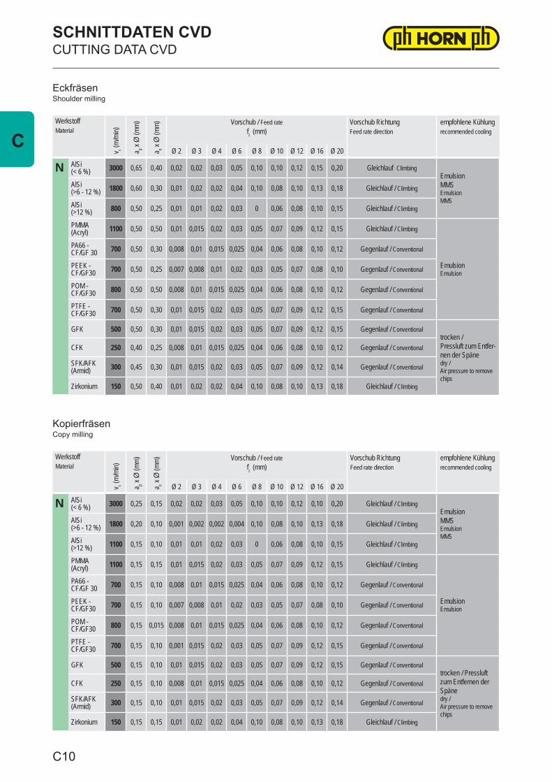
WerkstoffMaterial
v c (m/m
in)
a p x Ø
(mm)
a e x Ø
(mm) Vorschub / Feed rate
fz (mm)Vorschub RichtungFeed rate direction
empfohlene Kühlung recommended cooling
Ø 2 Ø 3 Ø 4 Ø 6 Ø 8 Ø 10 Ø 12 Ø 16 Ø 20
N AlSi (< 6 %) 3000 0,65 0,40 0,02 0,02 0,03 0,05 0,10 0,10 0,12 0,15 0,20 Gleichlauf Climbing
Emulsion MMSEmulsion MMS
AlSi (>6 - 12 %) 1800 0,60 0,30 0,01 0,02 0,02 0,04 0,10 0,08 0,10 0,13 0,18 Gleichlauf / Climbing
AlSi (>12 %) 800 0,50 0,25 0,01 0,01 0,02 0,03 0 0,06 0,08 0,10 0,15 Gleichlauf / Climbing
PMMA (Acryl) 1100 0,50 0,50 0,01 0,015 0,02 0,03 0,05 0,07 0,09 0,12 0,15 Gleichlauf / Climbing
EmulsionEmulsion
PA66 - CF/GF 30 700 0,50 0,30 0,008 0,01 0,015 0,025 0,04 0,06 0,08 0,10 0,12 Gegenlauf / Conventional
PEEK - CF/GF30 700 0,50 0,25 0,007 0,008 0,01 0,02 0,03 0,05 0,07 0,08 0,10 Gegenlauf / Conventional
POM - CF/GF30 800 0,50 0,50 0,008 0,01 0,015 0,025 0,04 0,06 0,08 0,10 0,12 Gegenlauf / Conventional
PTFE - CF/GF30 700 0,50 0,30 0,01 0,015 0,02 0,03 0,05 0,07 0,09 0,12 0,15 Gegenlauf / Conventional
GFK 500 0,50 0,30 0,01 0,015 0,02 0,03 0,05 0,07 0,09 0,12 0,15 Gegenlauf / Conventionaltrocken /Pressluft zum Entfer-nen der Spänedry / Air pressure to remove chips
CFK 250 0,40 0,25 0,008 0,01 0,015 0,025 0,04 0,06 0,08 0,10 0,12 Gegenlauf / Conventional
SFK/AFK (Armid) 300 0,45 0,30 0,01 0,015 0,02 0,03 0,05 0,07 0,09 0,12 0,14 Gegenlauf / Conventional
Zirkonium 150 0,50 0,40 0,01 0,02 0,02 0,04 0,10 0,08 0,10 0,13 0,18 Gleichlauf / Climbing
WerkstoffMaterial
v c (m/m
in)
a p x Ø
(mm)
a e x Ø
(mm) Vorschub / Feed rate
fz (mm)Vorschub RichtungFeed rate direction
empfohlene Kühlung recommended cooling
Ø 2 Ø 3 Ø 4 Ø 6 Ø 8 Ø 10 Ø 12 Ø 16 Ø 20
N AlSi (< 6 %) 3000 0,25 0,15 0,02 0,02 0,03 0,05 0,10 0,10 0,12 0,10 0,20 Gleichlauf / Climbing
EmulsionMMSEmulsionMMS
AlSi (>6 - 12 %) 1800 0,20 0,10 0,001 0,002 0,002 0,004 0,10 0,08 0,10 0,13 0,18 Gleichlauf / Climbing
AlSi (>12 %) 1100 0,15 0,10 0,01 0,01 0,02 0,03 0 0,06 0,08 0,10 0,15 Gleichlauf / Climbing
PMMA (Acryl) 1100 0,15 0,15 0,01 0,015 0,02 0,03 0,05 0,07 0,09 0,12 0,15 Gleichlauf / Climbing
EmulsionEmulsion
PA66 - CF/GF 30 700 0,15 0,10 0,008 0,01 0,015 0,025 0,04 0,06 0,08 0,10 0,12 Gegenlauf / Conventional
PEEK - CF/GF30 700 0,15 0,10 0,007 0,008 0,01 0,02 0,03 0,05 0,07 0,08 0,10 Gegenlauf / Conventional
POM - CF/GF30 800 0,15 0,015 0,008 0,01 0,015 0,025 0,04 0,06 0,08 0,10 0,12 Gegenlauf / Conventional
PTFE - CF/GF30 700 0,15 0,10 0,001 0,015 0,02 0,03 0,05 0,07 0,09 0,12 0,15 Gegenlauf / Conventional
GFK 500 0,15 0,10 0,01 0,015 0,02 0,03 0,05 0,07 0,09 0,12 0,15 Gegenlauf / Conventionaltrocken / Pressluft zum Entfernen der Spänedry / Air pressure to remove chips
CFK 250 0,15 0,10 0,008 0,01 0,015 0,025 0,04 0,06 0,08 0,10 0,12 Gegenlauf / Conventional
SFK/AFK (Armid) 300 0,15 0,10 0,01 0,015 0,02 0,03 0,05 0,07 0,09 0,12 0,14 Gegenlauf / Conventional
Zirkonium 150 0,15 0,15 0,01 0,02 0,02 0,04 0,10 0,08 0,10 0,13 0,18 Gleichlauf / Climbing
Eckfräsen
Kopierfräsen
Shoulder milling
Copy milling
SCHNITTDATEN CVDCUTTING DATA CVD
C10
C
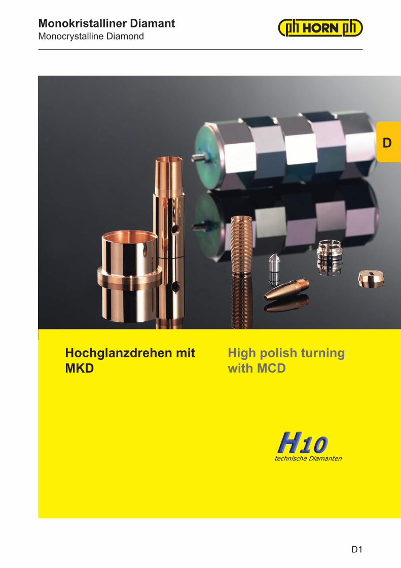
Monokristalliner DiamantMonocrystalline Diamond
Hochglanzdrehen mit MKD
High polish turning with MCD
D1
D
Monokristalliner DiamantMonocrystalline Diamond
Werkzeugschneiden der Oberklasse
Neben der hohen Härte von monokristallinen Diamanten ist vor allem das amorphe Gefüge Grundvoraussetzung für Ultrapräzisionszerspanung und Hochglanzbearbeitungen mit geometrisch bestimmter Schneide. Die extrem scharfen und makellosen Schneiden lassen Oberflächengenauigkeiten < Rz 0,02 μm zu. Die Qualität der Schneide ist hierbei das Abbild der erreichbaren Oberflächengüte.Bei der Herstellung der Werkzeuge wird besondere Beachtung auf die gitterorientierte, richtungsabhängigen Härtewerte der Einkristall-Diamanten gelegt. Nur so kann die maxi-male Standzeit erreicht werden. Die geometrische Auslegung der Schneide wird für die zu bearbeitenden Werkstoffe optimiert.MKD-bestückte Werkzeuge sind prädestiniert für die Finish-Bearbeitung von Nichteisen-metallen und deren Legierungen, Edelmetallen wie Gold und Platin oder transparenten Kunststoffen wie PMMA und PC.Eisenhaltige Metalle und faserverstärkte Kunststoffe sind grundsätzlich nicht für die Bearbeitung mit monokristallinem Diamant geeignet.
Ein umfangreiches Standardprogramm an MKD-bestückten Werkzeugen zum Drehen und Fräsen steht ab Lager zur Verfügung.
Top-class tool cutting edges
In addition to the high level of hardness demonstrated by monocrystalline diamonds, the amorphous structure in particular is a basic requirement for ultra-precision and high-precision machining with geometrically determined cutting edges. The extremely sharp and flawless cutting edges allow for surface accuracies of < Rz 0.02 μm. The quality of the cutting edge perfectly reflects the surface quality that can be achieved.When it comes to manufacturing tools, particular attention is paid to the crystal-system-based, direction-dependent hardness values of monocrystalline diamonds. This is the only way of ensuring that the maximum tool life is achieved. The geometric design of the cutting edge is optimised for the materials to be machined.MCD tools are ideally suited to finishing processes for non-ferrous metals and their alloys, precious metals such as gold and platinum or transparent plastics such as PMMA and PC.Ferrous metals and fibre-reinforced plastics are generally not suitable for machining with monocrystalline diamond.
An extensive standard range of MCD tools for turning and milling are available from stock.
D2
D
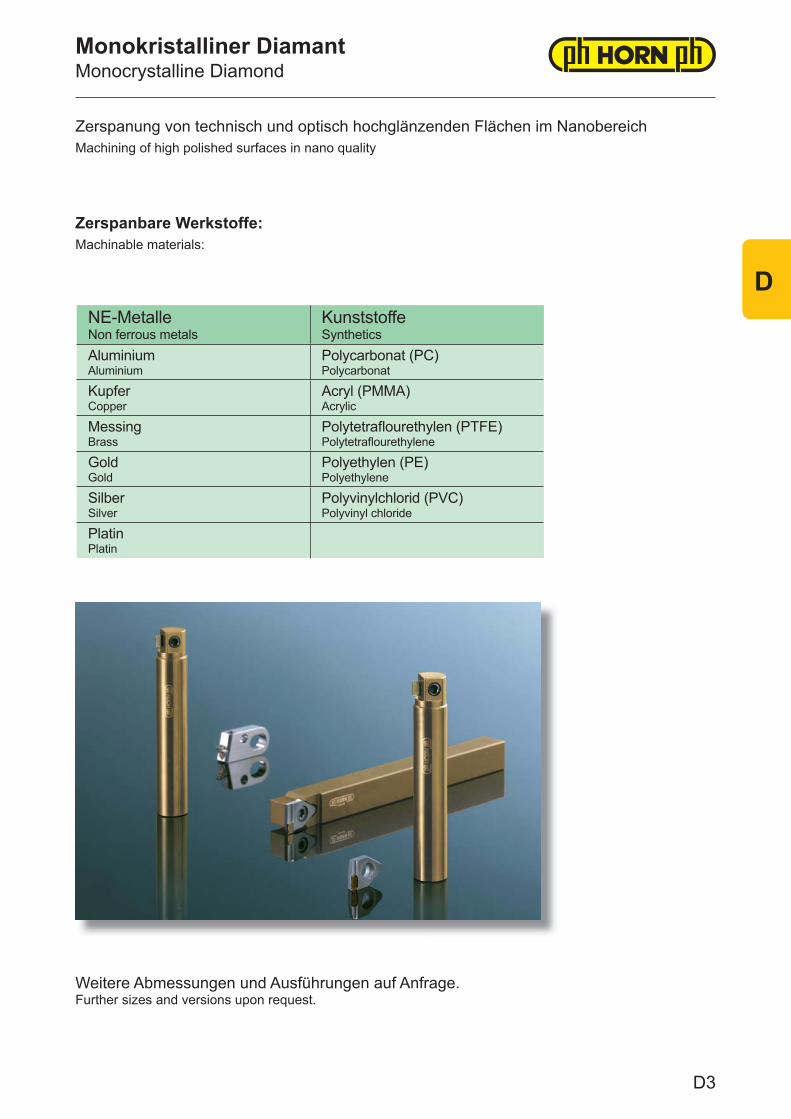
NE-MetalleNon ferrous metals
KunststoffeSynthetics
AluminiumAluminium
Polycarbonat (PC)Polycarbonat
KupferCopper
Acryl (PMMA)Acrylic
MessingBrass
Polytetrafl ourethylen (PTFE)Polytetrafl ourethylene
GoldGold
Polyethylen (PE)Polyethylene
SilberSilver
Polyvinylchlorid (PVC)Polyvinyl chloride
PlatinPlatin
Monokristalliner DiamantMonocrystalline Diamond
Machining of high polished surfaces in nano qualityZerspanung von technisch und optisch hochglänzenden Flächen im Nanobereich
Machinable materials:Zerspanbare Werkstoffe:
Weitere Abmessungen und Ausführungen auf Anfrage.Further sizes and versions upon request.
D3
D
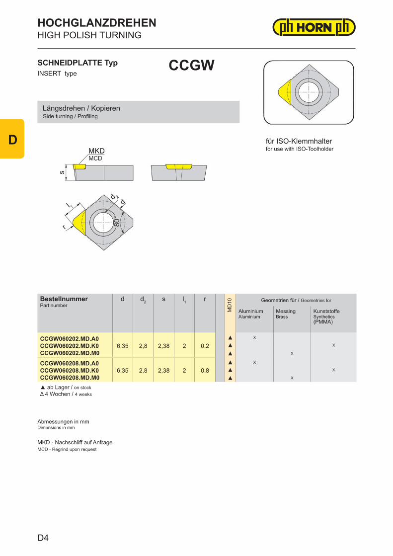
BestellnummerPart number
d d2 s l1 r
MD
10 Geometrien für / Geometries for
Aluminium Aluminium
MessingBrass
Kunststoffe Synthetics(PMMA)
CCGW060202.MD.A0CCGW060202.MD.K0CCGW060202.MD.M0
6,35 2,8 2,38 2 0,2▲ X
▲ X
▲ X
CCGW060208.MD.A0CCGW060208.MD.K0CCGW060208.MD.M0
6,35 2,8 2,38 2 0,8▲ X
▲ X
▲ X
▲ ab Lager / on stock Δ 4 Wochen / 4 weeks
HIGH POLISH TURNINGHOCHGLANZDREHEN
INSERT typeSCHNEIDPLATTE Typ CCGW
Abmessungen in mmDimensions in mm
for use with ISO-Toolholderfür ISO-Klemmhalter
Side turning / ProfilingLängsdrehen / Kopieren
MKD - Nachschliff auf AnfrageMCD - Regrind upon request
D4
D
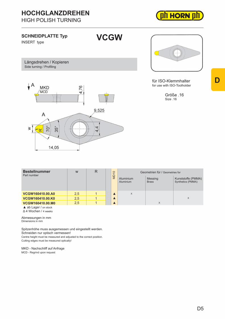
BestellnummerPart number
w R
MD
10 Geometrien für / Geometries for
Aluminium Aluminium
MessingBrass
Kunststoffe (PMMA)Synthetics (PMMA)
VCGW160410.00.A0 2,5 1 ▲ X
VCGW160410.00.K0 2,5 1 ▲ X
VCGW160410.00.M0 2,5 1 ▲ X
▲ ab Lager / on stock Δ 4 Wochen / 4 weeks
HIGH POLISH TURNINGHOCHGLANZDREHEN
INSERT typeSCHNEIDPLATTE Typ VCGW
Abmessungen in mmDimensions in mm
Größe .16Size .16
for use with ISO-Toolholderfür ISO-Klemmhalter
Side turning / ProfilingLängsdrehen / Kopieren
Spitzenhöhe muss ausgemessen und eingestellt werden.Schneiden nur optisch vermessen!Centre height must be measured and adjusted to the correct position.Cutting edges must be measured optically!
MKD - Nachschliff auf AnfrageMCD - Regrind upon request
D5
D
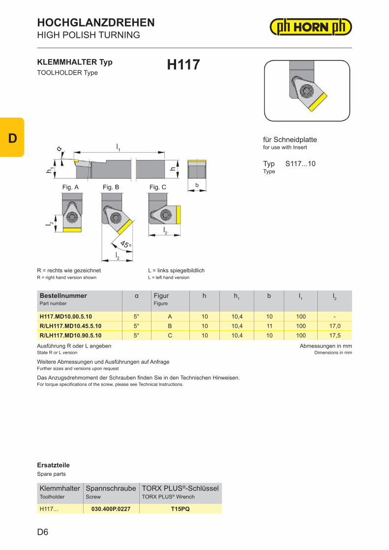
ErsatzteileSpare parts
KlemmhalterToolholder
SpannschraubeScrew
TORX PLUS®-SchlüsselTORX PLUS® Wrench
H117... 030.400P.0227 T15PQ
Ausführung R oder L angebenState R or L version
Abmessungen in mmDimensions in mm
Weitere Abmessungen und Ausführungen auf AnfrageFurther sizes and versions upon request
Das Anzugsdrehmoment der Schrauben finden Sie in den Technischen Hinweisen.For torque specifications of the screw, please see Technical Instructions.
BestellnummerPart number
α FigurFigure
h h1 b l1 l2
H117.MD10.00.5.10 5° A 10 10,4 10 100 -R/LH117.MD10.45.5.10 5° B 10 10,4 11 100 17,0R/LH117.MD10.90.5.10 5° C 10 10,4 10 100 17,5
KLEMMHALTER TypTOOLHOLDER Type
H117
R = rechts wie gezeichnetR = right hand version shown
L = links spiegelbildlichL = left hand version
für Schneidplattefor use with Insert
TypType
S117...10
HOCHGLANZDREHENHIGH POLISH TURNING
D6
D
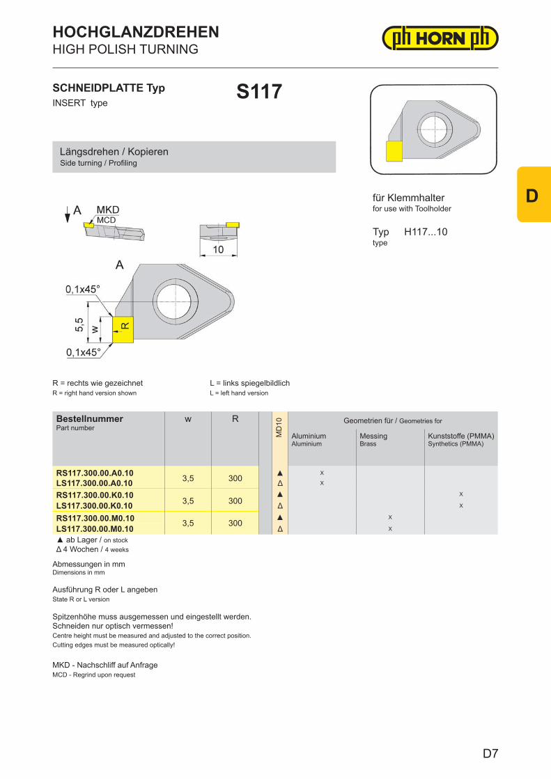
BestellnummerPart number
w R
MD
10 Geometrien für / Geometries for
Aluminium Aluminium
MessingBrass
Kunststoffe (PMMA)Synthetics (PMMA)
RS117.300.00.A0.10 3,5 300 ▲ X
LS117.300.00.A0.10 Δ X
RS117.300.00.K0.103,5 300
▲ X
LS117.300.00.K0.10 Δ X
RS117.300.00.M0.10 3,5 300▲ X
LS117.300.00.M0.10 Δ X
▲ ab Lager / on stock Δ 4 Wochen / 4 weeks
HIGH POLISH TURNINGHOCHGLANZDREHEN
INSERT typeSCHNEIDPLATTE Typ S117
Side turning / ProfilingLängsdrehen / Kopieren
Abmessungen in mmDimensions in mm
typeTyp
R = rechts wie gezeichnetR = right hand version shown
L = links spiegelbildlichL = left hand version
H117...10
for use with Toolholderfür Klemmhalter
Ausführung R oder L angebenState R or L version
Spitzenhöhe muss ausgemessen und eingestellt werden.Schneiden nur optisch vermessen!Centre height must be measured and adjusted to the correct position.Cutting edges must be measured optically!
MKD - Nachschliff auf AnfrageMCD - Regrind upon request
D7
D
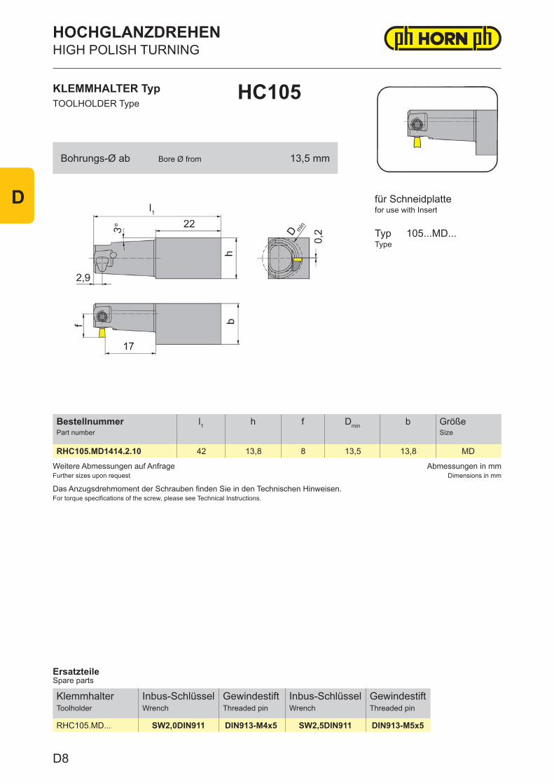
Weitere Abmessungen auf AnfrageFurther sizes upon request
Abmessungen in mmDimensions in mm
Das Anzugsdrehmoment der Schrauben finden Sie in den Technischen Hinweisen.For torque specifications of the screw, please see Technical Instructions.
BestellnummerPart number
l1 h f Dmin b GrößeSize
RHC105.MD1414.2.10 42 13,8 8 13,5 13,8 MD
ErsatzteileSpare parts
KlemmhalterToolholder
Inbus-SchlüsselWrench
GewindestiftThreaded pin
Inbus-SchlüsselWrench
GewindestiftThreaded pin
RHC105.MD... SW2,0DIN911 DIN913-M4x5 SW2,5DIN911 DIN913-M5x5
KLEMMHALTER TypTOOLHOLDER Type
HC105
für Schneidplattefor use with Insert
TypType
105...MD...
Bohrungs-Ø ab Bore Ø from 13,5 mm
HOCHGLANZDREHENHIGH POLISH TURNING
D8
D
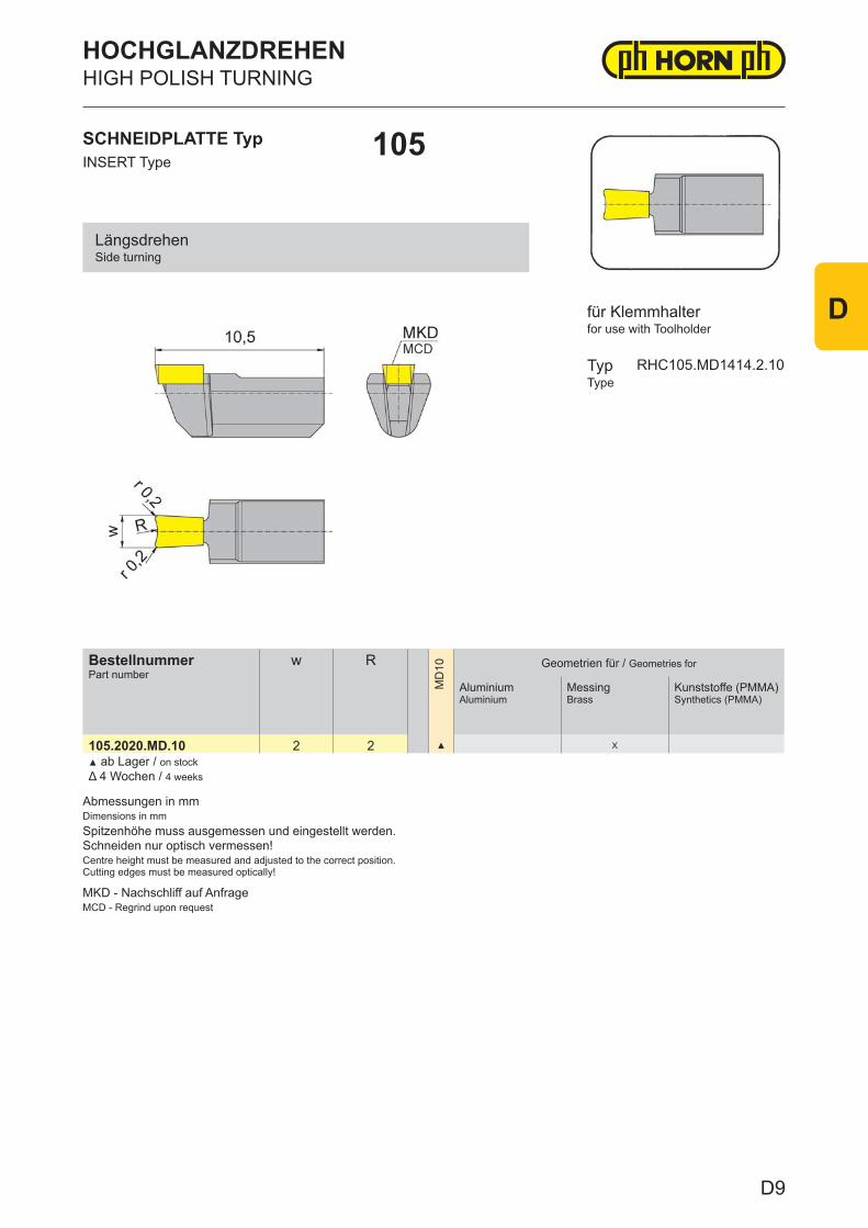
Abmessungen in mmDimensions in mmSpitzenhöhe muss ausgemessen und eingestellt werden.Schneiden nur optisch vermessen!Centre height must be measured and adjusted to the correct position.Cutting edges must be measured optically!
MKD - Nachschliff auf AnfrageMCD - Regrind upon request
BestellnummerPart number
w R
MD
10 Geometrien für / Geometries for
Aluminium Aluminium
MessingBrass
Kunststoffe (PMMA)Synthetics (PMMA)
105.2020.MD.10 2 2 ▲ X
▲ ab Lager / on stock Δ 4 Wochen / 4 weeks
SCHNEIDPLATTE TypINSERT Type
105
HOCHGLANZDREHENHIGH POLISH TURNING
for use with Toolholder
TypType
RHC105.MD1414.2.10
für Klemmhalter
LängsdrehenSide turning
D9
D
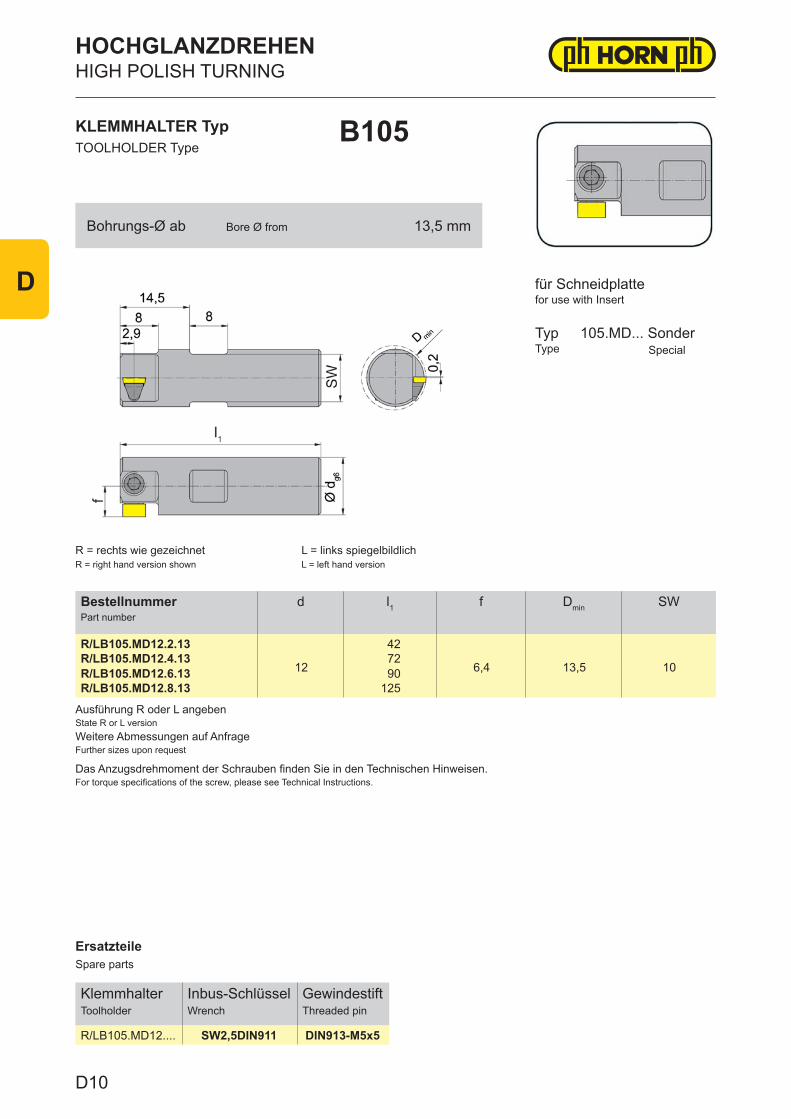
ErsatzteileSpare parts
KlemmhalterToolholder
Inbus-SchlüsselWrench
GewindestiftThreaded pin
R/LB105.MD12.... SW2,5DIN911 DIN913-M5x5
Ausführung R oder L angebenState R or L versionWeitere Abmessungen auf AnfrageFurther sizes upon request
Das Anzugsdrehmoment der Schrauben finden Sie in den Technischen Hinweisen.For torque specifications of the screw, please see Technical Instructions.
BestellnummerPart number
d l1 f Dmin SW
R/LB105.MD12.2.13
12
42
6,4 13,5 10R/LB105.MD12.4.13 72R/LB105.MD12.6.13 90R/LB105.MD12.8.13 125
KLEMMHALTER TypTOOLHOLDER Type
B105
R = rechts wie gezeichnetR = right hand version shown
L = links spiegelbildlichL = left hand version
für Schneidplattefor use with Insert
TypType
105.MD... Sonder Special
Bohrungs-Ø ab Bore Ø from 13,5 mm
HOCHGLANZDREHENHIGH POLISH TURNING
D10
D
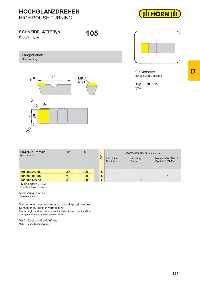
BestellnummerPart number
w R
MD
10 Geometrien für / Geometries for
Aluminium Aluminium
MessingBrass
Kunststoffe (PMMA)Synthetics (PMMA)
105.300.AD.06 3,5 300 ▲ X
105.300.KD.06 3,5 300 ▲ X
105.300.MD.06 3,5 300 ▲ X
▲ ab Lager / on stock Δ 4 Wochen / 4 weeks
HIGH POLISH TURNINGHOCHGLANZDREHEN
105
Abmessungen in mmDimensions in mm
Typ NH105type
Side turningLängsdrehen
INSERT typeSCHNEIDPLATTE Typ
Spitzenhöhe muss ausgemessen und eingestellt werden.Schneiden nur optisch vermessen!Centre height must be measured and adjusted to the correct position.Cutting edges must be measured optically!
for use with Cassettefür Kassette
MKD - Nachschliff auf AnfrageMCD - Regrind upon request
D11
D
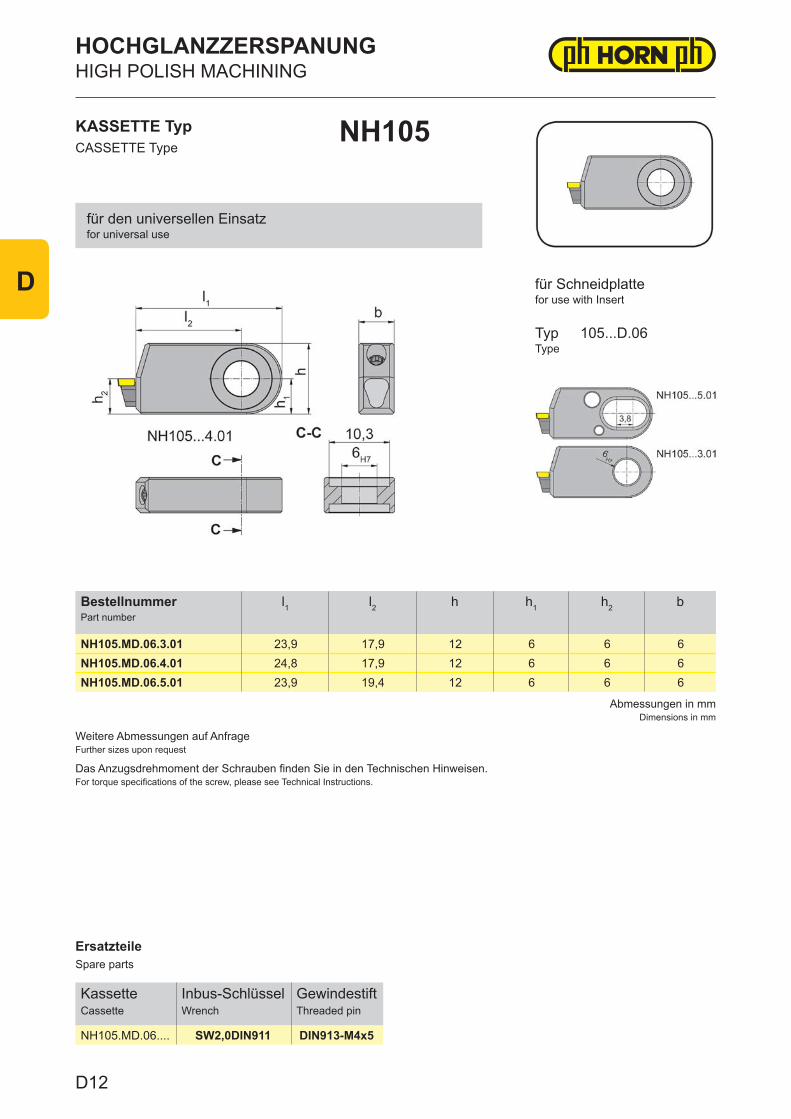
ErsatzteileSpare parts
KassetteCassette
Inbus-SchlüsselWrench
GewindestiftThreaded pin
NH105.MD.06.... SW2,0DIN911 DIN913-M4x5
Abmessungen in mmDimensions in mm
Weitere Abmessungen auf AnfrageFurther sizes upon request
Das Anzugsdrehmoment der Schrauben finden Sie in den Technischen Hinweisen.For torque specifications of the screw, please see Technical Instructions.
BestellnummerPart number
l1 l2 h h1 h2 b
NH105.MD.06.3.01 23,9 17,9 12 6 6 6NH105.MD.06.4.01 24,8 17,9 12 6 6 6NH105.MD.06.5.01 23,9 19,4 12 6 6 6
KASSETTE TypCASSETTE Type
NH105
für Schneidplattefor use with Insert
TypType
105...D.06
für den universellen Einsatzfor universal use
HOCHGLANZZERSPANUNGHIGH POLISH MACHINING
D12
D
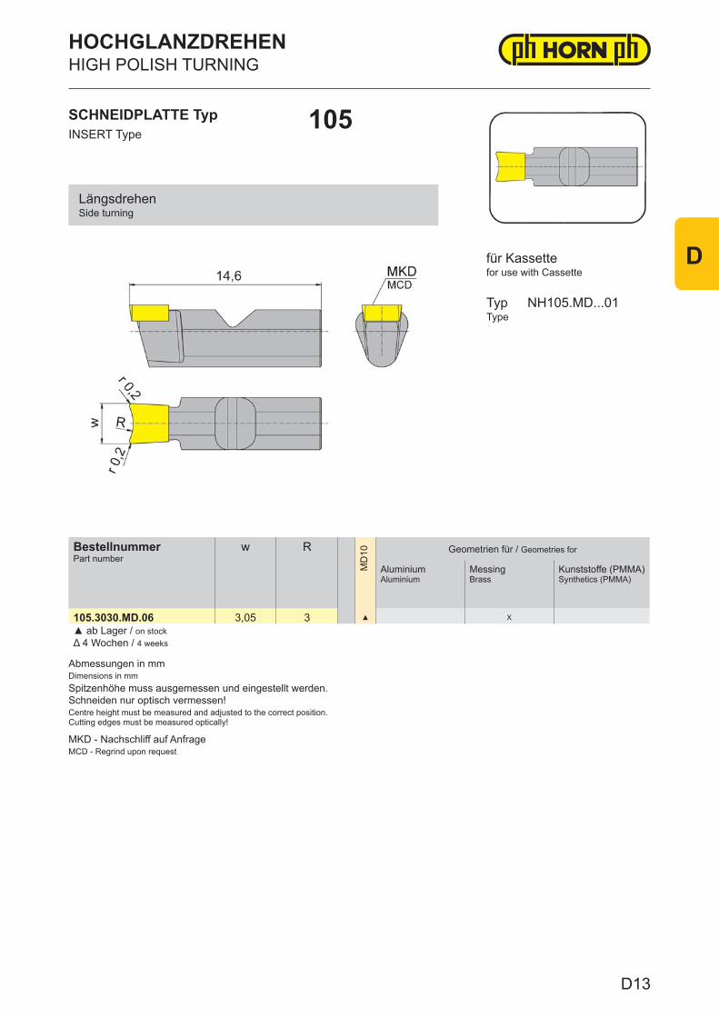
Abmessungen in mmDimensions in mmSpitzenhöhe muss ausgemessen und eingestellt werden.Schneiden nur optisch vermessen!Centre height must be measured and adjusted to the correct position.Cutting edges must be measured optically!
MKD - Nachschliff auf AnfrageMCD - Regrind upon request
BestellnummerPart number
w R
MD
10 Geometrien für / Geometries for
Aluminium Aluminium
MessingBrass
Kunststoffe (PMMA)Synthetics (PMMA)
105.3030.MD.06 3,05 3 ▲ X
▲ ab Lager / on stock Δ 4 Wochen / 4 weeks
SCHNEIDPLATTE TypINSERT Type
105
HOCHGLANZDREHENHIGH POLISH TURNING
for use with Cassette
TypType
NH105.MD...01
für Kassette
LängsdrehenSide turning
D13
D
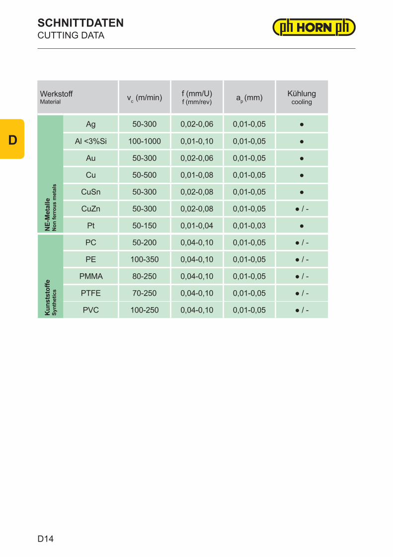
WerkstoffMaterial vc (m/min) f (mm/U)
f (mm/rev) ap (mm) Kühlungcooling
NE-
Met
alle
Non
ferr
ous
met
als
Ag 50-300 0,02-0,06 0,01-0,05 ●
Al <3%Si 100-1000 0,01-0,10 0,01-0,05 ●
Au 50-300 0,02-0,06 0,01-0,05 ●
Cu 50-500 0,01-0,08 0,01-0,05 ●
CuSn 50-300 0,02-0,08 0,01-0,05 ●
CuZn 50-300 0,02-0,08 0,01-0,05 ● / -
Pt 50-150 0,01-0,04 0,01-0,03 ●
Kun
stst
offe
Synt
hetic
s
PC 50-200 0,04-0,10 0,01-0,05 ● / -
PE 100-350 0,04-0,10 0,01-0,05 ● / -
PMMA 80-250 0,04-0,10 0,01-0,05 ● / -
PTFE 70-250 0,04-0,10 0,01-0,05 ● / -
PVC 100-250 0,04-0,10 0,01-0,05 ● / -
SCHNITTDATENCUTTING DATA
D14
D
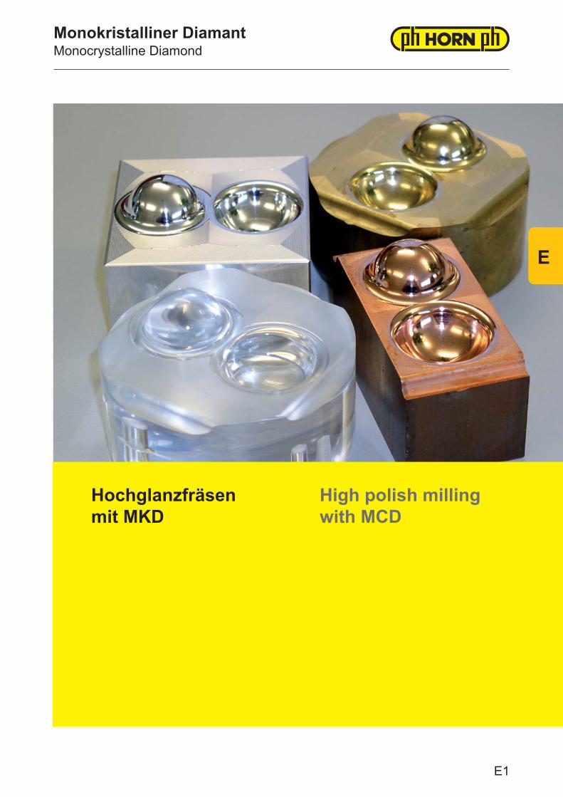
Monokristalliner DiamantMonocrystalline Diamond
Hochglanzfräsen mit MKD
High polish milling with MCD
E1
E
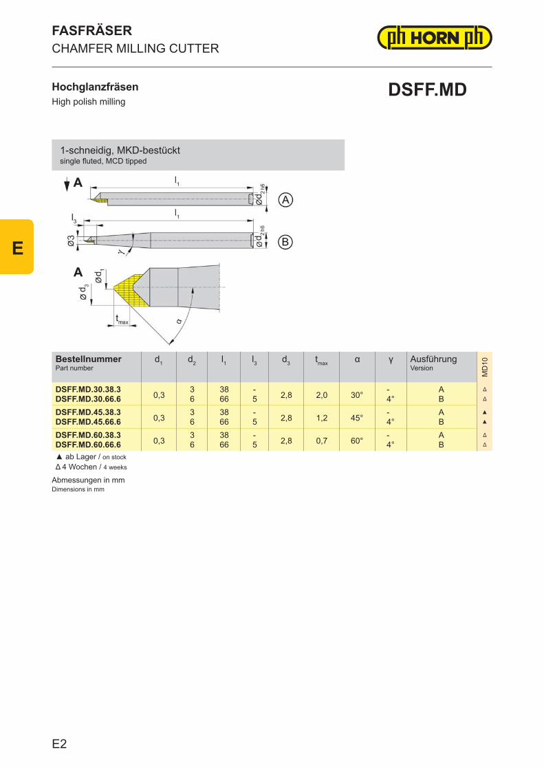
Abmessungen in mmDimensions in mm
BestellnummerPart number
d1 d2 l1 l3 d3 tmax α γ AusführungVersion
MD
10
DSFF.MD.30.38.30,3
3 38 -2,8 2,0 30°
- A Δ
DSFF.MD.30.66.6 6 66 5 4° B Δ
DSFF.MD.45.38.30,3
3 38 -2,8 1,2 45°
- A ▲
DSFF.MD.45.66.6 6 66 5 4° B ▲
DSFF.MD.60.38.30,3
3 38 -2,8 0,7 60°
- A Δ
DSFF.MD.60.66.6 6 66 5 4° B Δ
▲ ab Lager / on stockΔ 4 Wochen / 4 weeks
HochglanzfräsenHigh polish milling
FASFRÄSERCHAMFER MILLING CUTTER
DSFF.MD
1-schneidig, MKD-bestücktsingle fluted, MCD tipped
E2
E
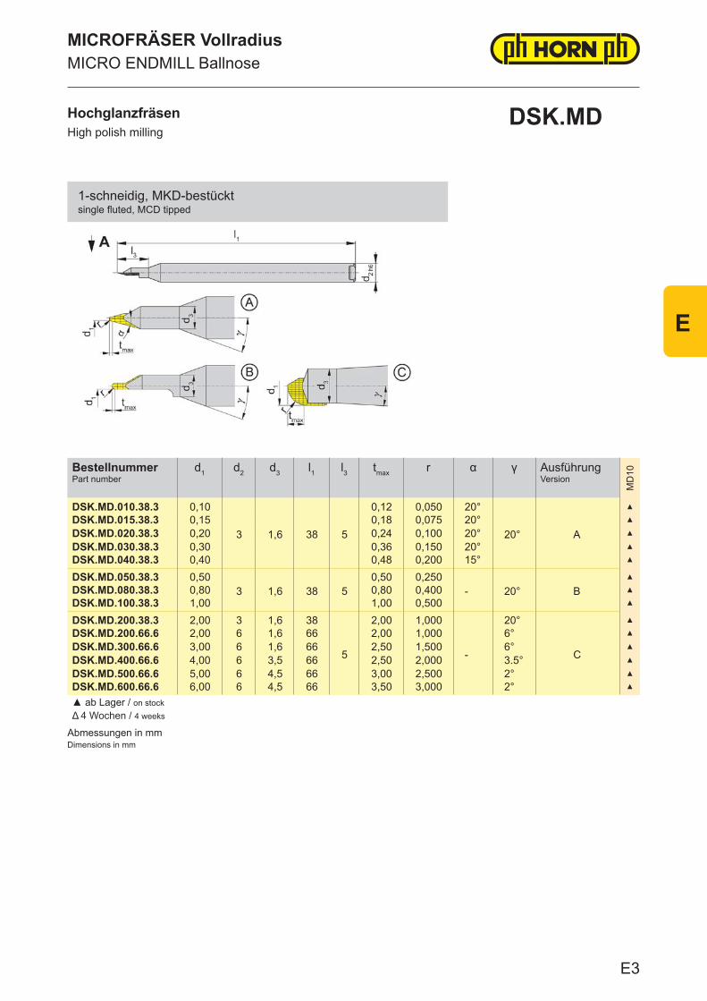
Abmessungen in mmDimensions in mm
BestellnummerPart number
d1 d2 d3 l1 l3 tmax r α γ AusführungVersion
MD
10
DSK.MD.010.38.3 0,10
3 1,6 38 5
0,12 0,050 20°
20° A
▲
DSK.MD.015.38.3 0,15 0,18 0,075 20° ▲
DSK.MD.020.38.3 0,20 0,24 0,100 20° ▲
DSK.MD.030.38.3 0,30 0,36 0,150 20° ▲
DSK.MD.040.38.3 0,40 0,48 0,200 15° ▲
DSK.MD.050.38.3 0,503 1,6 38 5
0,50 0,250- 20° B
▲
DSK.MD.080.38.3 0,80 0,80 0,400 ▲
DSK.MD.100.38.3 1,00 1,00 0,500 ▲
DSK.MD.200.38.3 2,00 3 1,6 38
5
2,00 1,000
-
20°
C
▲
DSK.MD.200.66.6 2,00 6 1,6 66 2,00 1,000 6° ▲
DSK.MD.300.66.6 3,00 6 1,6 66 2,50 1,500 6° ▲
DSK.MD.400.66.6 4,00 6 3,5 66 2,50 2,000 3.5° ▲
DSK.MD.500.66.6 5,00 6 4,5 66 3,00 2,500 2° ▲
DSK.MD.600.66.6 6,00 6 4,5 66 3,50 3,000 2° ▲
▲ ab Lager / on stockΔ 4 Wochen / 4 weeks
MICROFRÄSER VollradiusMICRO ENDMILL Ballnose
HochglanzfräsenHigh polish milling
DSK.MD
1-schneidig, MKD-bestücktsingle fluted, MCD tipped
E3
E
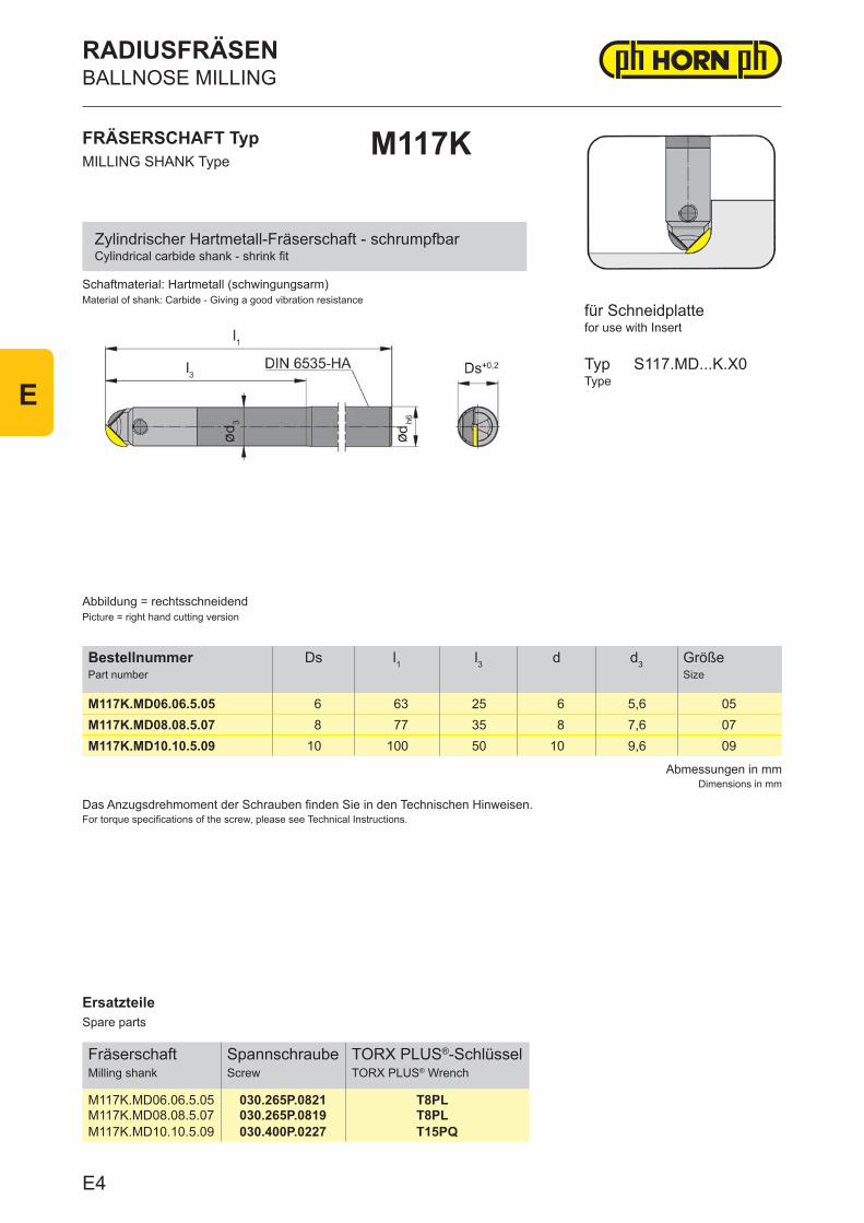
ErsatzteileSpare parts
FräserschaftMilling shank
SpannschraubeScrew
TORX PLUS®-SchlüsselTORX PLUS® Wrench
M117K.MD06.06.5.05 030.265P.0821 T8PLM117K.MD08.08.5.07 030.265P.0819 T8PLM117K.MD10.10.5.09 030.400P.0227 T15PQ
Abmessungen in mmDimensions in mm
Das Anzugsdrehmoment der Schrauben finden Sie in den Technischen Hinweisen.For torque specifications of the screw, please see Technical Instructions.
BestellnummerPart number
Ds l1 l3 d d3 GrößeSize
M117K.MD06.06.5.05 6 63 25 6 5,6 05M117K.MD08.08.5.07 8 77 35 8 7,6 07M117K.MD10.10.5.09 10 100 50 10 9,6 09
Schaftmaterial: Hartmetall (schwingungsarm)Material of shank: Carbide - Giving a good vibration resistance
FRÄSERSCHAFT TypMILLING SHANK Type
M117K
Abbildung = rechtsschneidendPicture = right hand cutting version
für Schneidplattefor use with Insert
TypType
S117.MD...K.X0
Zylindrischer Hartmetall-Fräserschaft - schrumpfbarCylindrical carbide shank - shrink fit
RADIUSFRÄSENBALLNOSE MILLING
E4
E
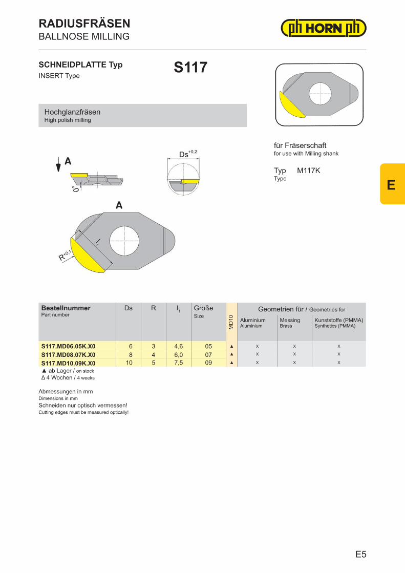
Abmessungen in mmDimensions in mmSchneiden nur optisch vermessen!Cutting edges must be measured optically!
BestellnummerPart number
Ds R l1 GrößeSize
MD
10
Geometrien für / Geometries for
Aluminium Aluminium
MessingBrass
Kunststoffe (PMMA)Synthetics (PMMA)
S117.MD06.05K.X0 6 3 4,6 05 ▲ X X X
S117.MD08.07K.X0 8 4 6,0 07 ▲ X X X
S117.MD10.09K.X0 10 5 7,5 09 ▲ X X X
▲ ab Lager / on stock Δ 4 Wochen / 4 weeks
SCHNEIDPLATTE TypINSERT Type
S117
RADIUSFRÄSENBALLNOSE MILLING
for use with Milling shank
TypType
M117K
für Fräserschaft
HochglanzfräsenHigh polish milling
E5
E
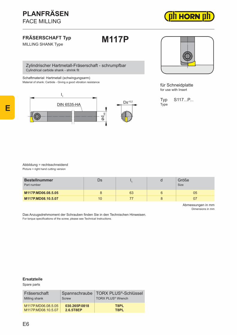
ErsatzteileSpare parts
FräserschaftMilling shank
SpannschraubeScrew
TORX PLUS®-SchlüsselTORX PLUS® Wrench
M117P.MD06.08.5.05 030.265P.0818 T8PLM117P.MD08.10.5.07 2.6.5T8EP T8PL
Abmessungen in mmDimensions in mm
Das Anzugsdrehmoment der Schrauben finden Sie in den Technischen Hinweisen.For torque specifications of the screw, please see Technical Instructions.
BestellnummerPart number
Ds l1 d GrößeSize
M117P.MD06.08.5.05 8 63 6 05M117P.MD08.10.5.07 10 77 8 07
Schaftmaterial: Hartmetall (schwingungsarm)Material of shank: Carbide - Giving a good vibration resistance
FRÄSERSCHAFT TypMILLING SHANK Type
M117P
Abbildung = rechtsschneidendPicture = right hand cutting version
für Schneidplattefor use with Insert
TypType
S117...P...
Zylindrischer Hartmetall-Fräserschaft - schrumpfbarCylindrical carbide shank - shrink fit
PLANFRÄSENFACE MILLING
E6
E
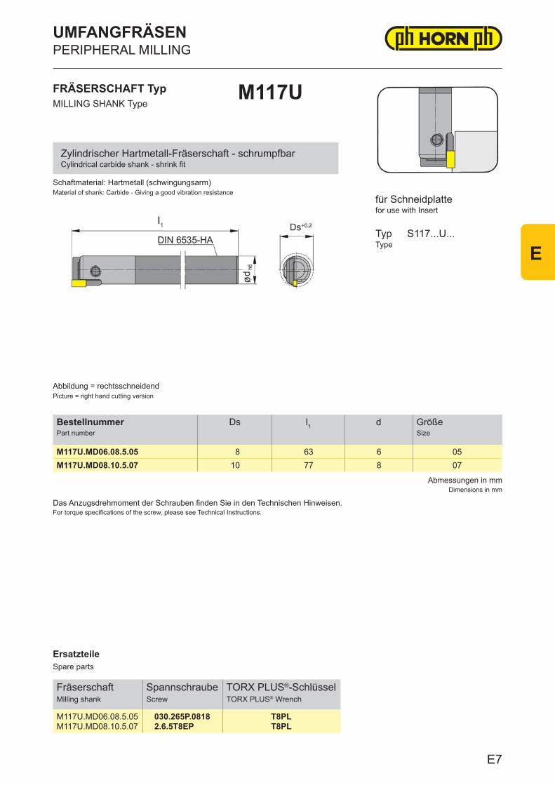
ErsatzteileSpare parts
FräserschaftMilling shank
SpannschraubeScrew
TORX PLUS®-SchlüsselTORX PLUS® Wrench
M117U.MD06.08.5.05 030.265P.0818 T8PLM117U.MD08.10.5.07 2.6.5T8EP T8PL
Abmessungen in mmDimensions in mm
Das Anzugsdrehmoment der Schrauben finden Sie in den Technischen Hinweisen.For torque specifications of the screw, please see Technical Instructions.
BestellnummerPart number
Ds l1 d GrößeSize
M117U.MD06.08.5.05 8 63 6 05M117U.MD08.10.5.07 10 77 8 07
FRÄSERSCHAFT TypMILLING SHANK Type
M117U
für Schneidplattefor use with Insert
TypType
S117...U...
Abbildung = rechtsschneidendPicture = right hand cutting version
Schaftmaterial: Hartmetall (schwingungsarm)Material of shank: Carbide - Giving a good vibration resistance
Zylindrischer Hartmetall-Fräserschaft - schrumpfbarCylindrical carbide shank - shrink fit
UMFANGFRÄSENPERIPHERAL MILLING
E7
E
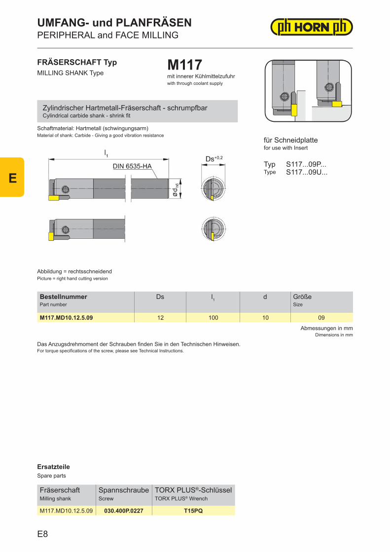
ErsatzteileSpare parts
FräserschaftMilling shank
SpannschraubeScrew
TORX PLUS®-SchlüsselTORX PLUS® Wrench
M117.MD10.12.5.09 030.400P.0227 T15PQ
Abmessungen in mmDimensions in mm
Das Anzugsdrehmoment der Schrauben finden Sie in den Technischen Hinweisen.For torque specifications of the screw, please see Technical Instructions.
BestellnummerPart number
Ds l1 d GrößeSize
M117.MD10.12.5.09 12 100 10 09
Schaftmaterial: Hartmetall (schwingungsarm)Material of shank: Carbide - Giving a good vibration resistance
FRÄSERSCHAFT TypMILLING SHANK Type
M117mit innerer Kühlmittelzufuhrwith through coolant supply
Abbildung = rechtsschneidendPicture = right hand cutting version
für Schneidplattefor use with Insert
TypType
S117...09P...S117...09U...
Zylindrischer Hartmetall-Fräserschaft - schrumpfbarCylindrical carbide shank - shrink fit
UMFANG- und PLANFRÄSENPERIPHERAL and FACE MILLING
E8
E
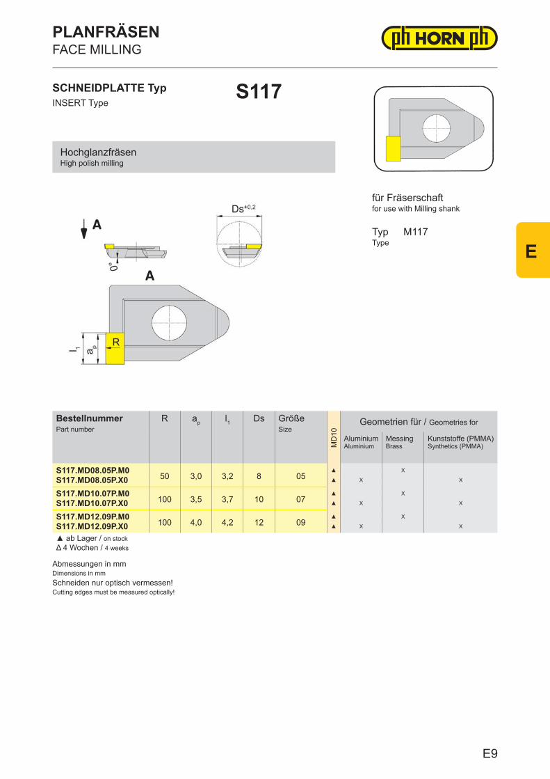
Abmessungen in mmDimensions in mmSchneiden nur optisch vermessen!Cutting edges must be measured optically!
BestellnummerPart number
R ap l1 Ds GrößeSize
MD
10
Geometrien für / Geometries for
Aluminium Aluminium
MessingBrass
Kunststoffe (PMMA)Synthetics (PMMA)
S117.MD08.05P.M050 3,0 3,2 8 05
▲ X
S117.MD08.05P.X0 ▲ X X
S117.MD10.07P.M0100 3,5 3,7 10 07
▲ X
S117.MD10.07P.X0 ▲ X X
S117.MD12.09P.M0100 4,0 4,2 12 09
▲ X
S117.MD12.09P.X0 ▲ X X
▲ ab Lager / on stock Δ 4 Wochen / 4 weeks
SCHNEIDPLATTE TypINSERT Type
S117
PLANFRÄSENFACE MILLING
for use with Milling shank
TypType
M117
für Fräserschaft
HochglanzfräsenHigh polish milling
E9
E
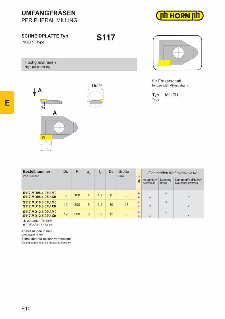
Abmessungen in mmDimensions in mmSchneiden nur optisch vermessen!Cutting edges must be measured optically!
BestellnummerPart number
Ds R ap l1 Ds GrößeSize
MD
10
Geometrien für / Geometries for
Aluminium Aluminium
MessingBrass
Kunststoffe (PMMA)Synthetics (PMMA)
S117.MD08.4.05U.M08 100 4 4,2 8 05
Δ X
S117.MD08.4.05U.X0 Δ X X
S117.MD10.5.07U.M010 300 5 5,2 10 07
Δ X
S117.MD10.5.07U.X0 Δ X X
S117.MD12.5.09U.M012 300 5 5,2 12 09
Δ X
S117.MD12.5.09U.X0 Δ X X
▲ ab Lager / on stock Δ 4 Wochen / 4 weeks
SCHNEIDPLATTE TypINSERT Type
S117
UMFANGFRÄSENPERIPHERAL MILLING
for use with Milling shank
TypType
M117U
für Fräserschaft
HochglanzfräsenHigh polish milling
E10
E
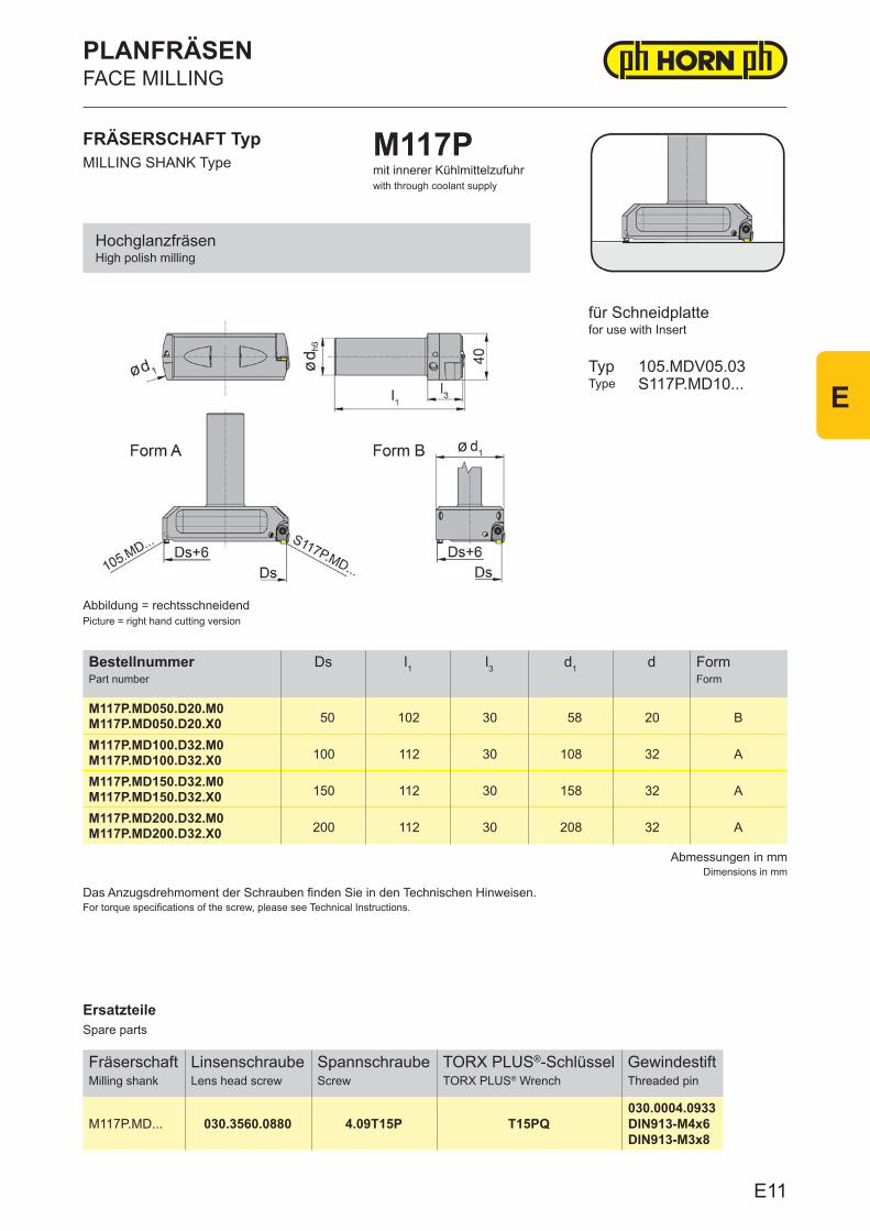
ErsatzteileSpare parts
FräserschaftMilling shank
LinsenschraubeLens head screw
SpannschraubeScrew
TORX PLUS®-SchlüsselTORX PLUS® Wrench
GewindestiftThreaded pin
M117P.MD... 030.3560.0880 4.09T15P T15PQ030.0004.0933DIN913-M4x6DIN913-M3x8
Abmessungen in mmDimensions in mm
Das Anzugsdrehmoment der Schrauben finden Sie in den Technischen Hinweisen.For torque specifications of the screw, please see Technical Instructions.
BestellnummerPart number
Ds l1 l3 d1 d FormForm
M117P.MD050.D20.M050 102 30 58 20 BM117P.MD050.D20.X0
M117P.MD100.D32.M0100 112 30 108 32 AM117P.MD100.D32.X0
M117P.MD150.D32.M0150 112 30 158 32 AM117P.MD150.D32.X0
M117P.MD200.D32.M0200 112 30 208 32 AM117P.MD200.D32.X0
FRÄSERSCHAFT TypMILLING SHANK Type
M117Pmit innerer Kühlmittelzufuhrwith through coolant supply
für Schneidplattefor use with Insert
TypType
105.MDV05.03S117P.MD10...
Abbildung = rechtsschneidendPicture = right hand cutting version
HochglanzfräsenHigh polish milling
PLANFRÄSENFACE MILLING
E11
E
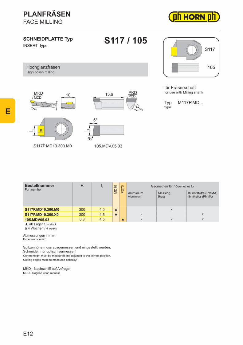
BestellnummerPart number
R l1
MD
10
PD
75 Geometrien für / Geometries for
Aluminium Aluminium
MessingBrass
Kunststoffe (PMMA)Synthetics (PMMA)
S117P.MD10.300.M0 300 4,5 ▲ X
S117P.MD10.300.X0 300 4,5 ▲ X X
105.MDV05.03 0,3 4,5 ▲ X X X
▲ ab Lager / on stock Δ 4 Wochen / 4 weeks
FACE MILLINGPLANFRÄSEN
S117 / 105
Abmessungen in mmDimensions in mm
Typ M117P.MD...type
for use with Milling shankfür Fräserschaft
High polish millingHochglanzfräsen
INSERT typeSCHNEIDPLATTE Typ
Spitzenhöhe muss ausgemessen und eingestellt werden.Schneiden nur optisch vermessen!Centre height must be measured and adjusted to the correct position.Cutting edges must be measured optically!
MKD - Nachschliff auf AnfrageMCD - Regrind upon request
E12
E

ErsatzteileSpare parts
KassetteCassette
Inbus-SchlüsselWrench
GewindestiftThreaded pin
NH105.MD.06.... SW2,0DIN911 DIN913-M4x5
Abmessungen in mmDimensions in mm
Weitere Abmessungen auf AnfrageFurther sizes upon request
Das Anzugsdrehmoment der Schrauben finden Sie in den Technischen Hinweisen.For torque specifications of the screw, please see Technical Instructions.
BestellnummerPart number
l1 l2 h h1 h2 b
NH105.MD.06.3.01 23,9 17,9 12 6 6 6NH105.MD.06.4.01 24,8 17,9 12 6 6 6NH105.MD.06.5.01 23,9 19,4 12 6 6 6
KASSETTE TypCASSETTE Type
NH105
für Schneidplattefor use with Insert
TypType
105...F.06105...D.06
für den universellen Einsatzfor universal use
HOCHGLANZZERSPANUNGHIGH POLISH MACHINING
E13
E
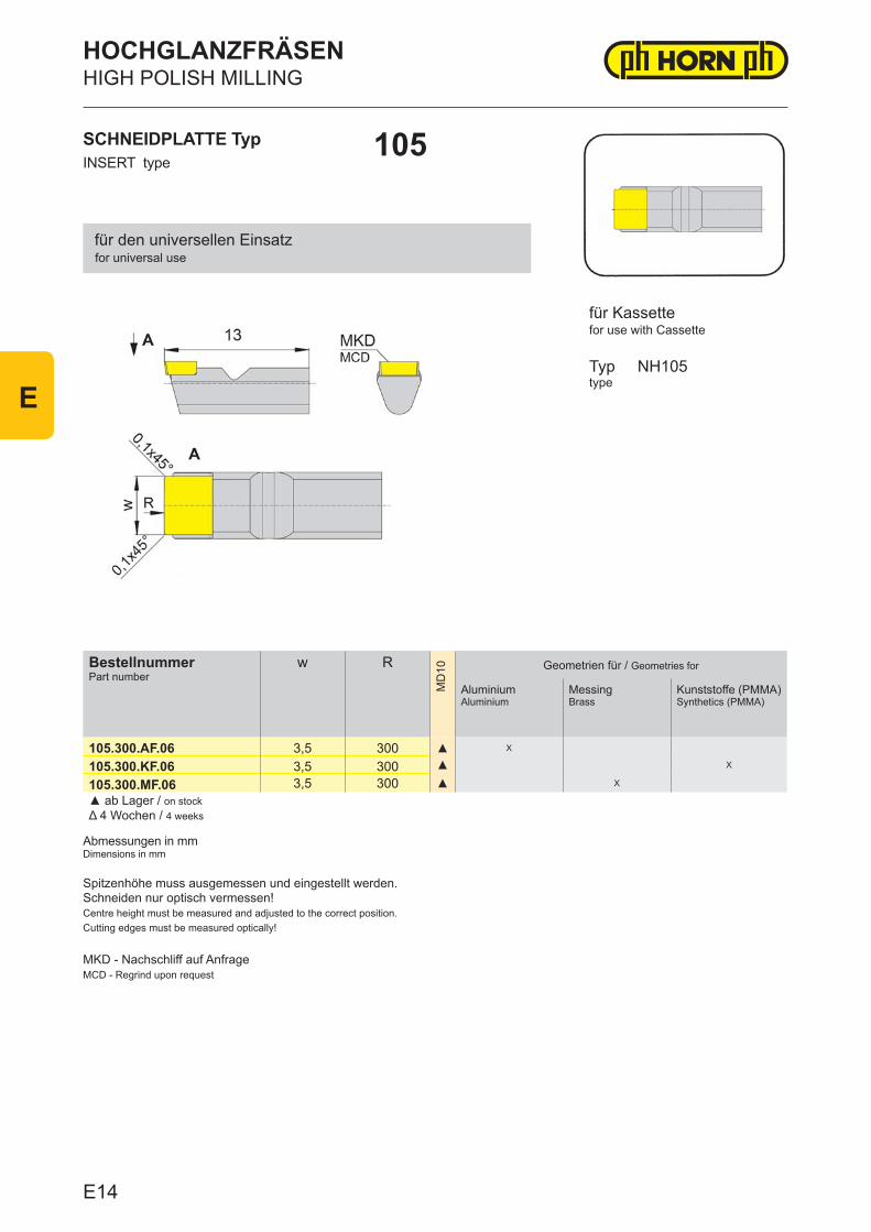
BestellnummerPart number
w R
MD
10 Geometrien für / Geometries for
Aluminium Aluminium
MessingBrass
Kunststoffe (PMMA)Synthetics (PMMA)
105.300.AF.06 3,5 300 ▲ X
105.300.KF.06 3,5 300 ▲ X
105.300.MF.06 3,5 300 ▲ X
▲ ab Lager / on stock Δ 4 Wochen / 4 weeks
HIGH POLISH MILLINGHOCHGLANZFRÄSEN
105
Abmessungen in mmDimensions in mm
Typ NH105type
for use with Cassettefür Kassette
for universal usefür den universellen Einsatz
INSERT typeSCHNEIDPLATTE Typ
Spitzenhöhe muss ausgemessen und eingestellt werden.Schneiden nur optisch vermessen!Centre height must be measured and adjusted to the correct position.Cutting edges must be measured optically!
MKD - Nachschliff auf AnfrageMCD - Regrind upon request
E14
E
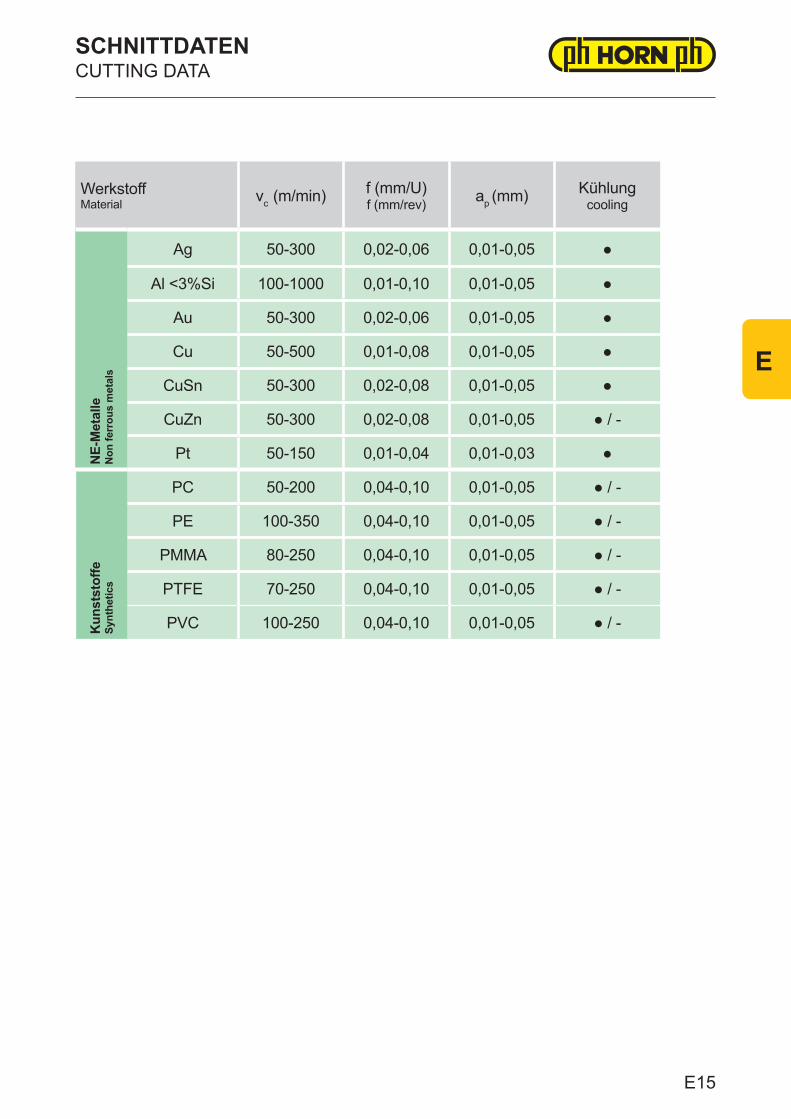
WerkstoffMaterial vc (m/min) f (mm/U)
f (mm/rev) ap (mm) Kühlungcooling
NE-
Met
alle
Non
ferr
ous
met
als
Ag 50-300 0,02-0,06 0,01-0,05 ●
Al <3%Si 100-1000 0,01-0,10 0,01-0,05 ●
Au 50-300 0,02-0,06 0,01-0,05 ●
Cu 50-500 0,01-0,08 0,01-0,05 ●
CuSn 50-300 0,02-0,08 0,01-0,05 ●
CuZn 50-300 0,02-0,08 0,01-0,05 ● / -
Pt 50-150 0,01-0,04 0,01-0,03 ●
Kun
stst
offe
Synt
hetic
s
PC 50-200 0,04-0,10 0,01-0,05 ● / -
PE 100-350 0,04-0,10 0,01-0,05 ● / -
PMMA 80-250 0,04-0,10 0,01-0,05 ● / -
PTFE 70-250 0,04-0,10 0,01-0,05 ● / -
PVC 100-250 0,04-0,10 0,01-0,05 ● / -
SCHNITTDATENCUTTING DATA
E15
E
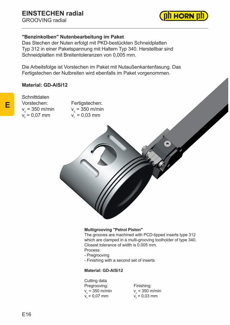
″Benzinkolben″ Nutenbearbeitung im PaketDas Stechen der Nuten erfolgt mit PKD-bestückten Schneidplatten Typ 312 in einer Paketspannung mit Haltern Typ 340. Herstellbar sind Schneidplatten mit Breitentoleranzen von 0,005 mm. Die Arbeitsfolge ist Vorstechen im Paket mit Nutaußenkantenfasung. Das Fertigstechen der Nutbreiten wird ebenfalls im Paket vorgenommen.
Material: GD-AlSi12
Schnittdaten Vorstechen: Fertigstechen:vc = 350 m/min vc = 350 m/minvf = 0,07 mm vf = 0,03 mm
EINSTECHEN radialGROOVING radial
Multigrooving ″Petrol Piston″The grooves are machined with PCD-tipped inserts type 312 which are clamped in a multi-grooving toolholder of type 340. Closest tolerance of width is 0.005 mm.Process:- Pregrooving- Finishing with a second set of inserts
Material: GD-AlSi12
Cutting dataPregrooving: Finishing:vc = 350 m/min vc = 350 m/minvf = 0,07 mm vf = 0,03 mm
E16
E
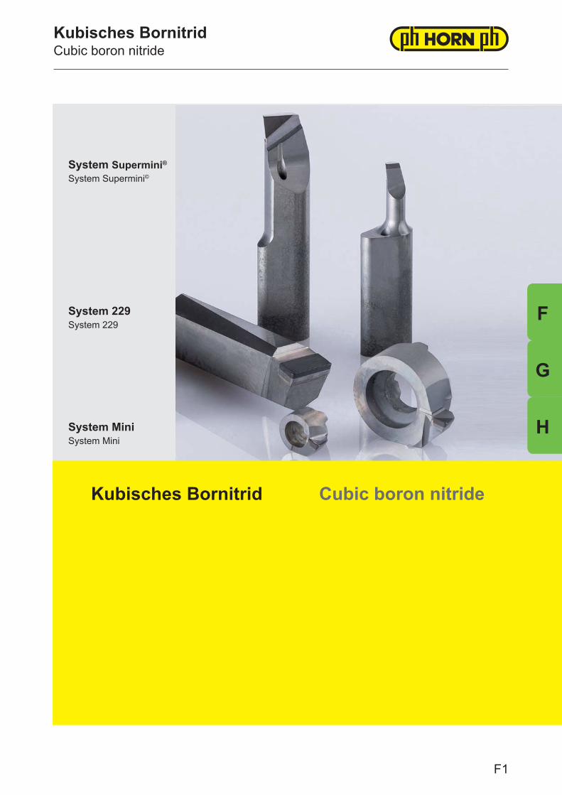
Kubisches BornitridCubic boron nitride
System Supermini® System Supermini©
System 229System 229
Kubisches Bornitrid Cubic boron nitride
System MiniSystem Mini
F1
F
H
F
G
CB07 CB10
Hartbearbeitung von Stahl (45-70 HRC) im Glatt- und leicht unterbrochenen SchnittHard machining of steel (45-70 HRC) with a smooth and lightly interrupted cut
CB50
Hartbearbeitung von Stahl (45-70 HRC) im stark unterbrochenen SchnittHard machining of steel (45-70 HRC) with a heavily interrupted cut
GussbearbeitungCast iron machining
Sinterwerkstoffe, Feinbearbeitung von SuperlegierungenSintered materials, precision machining of superalloys
Kubisches Bornitrid, nach Diamant das zweithärteste Material, ist durch die einmalige Kombination von physikalischen, mechanischen und chemischen Eigenschaften charakterisiert. Vor allem die hohe thermische Beständigkeit und Härte ermöglicht eine höchst wirtschaftliche Bearbeitung von gehärtetem Stahl mit geometrisch bestimmter Schneide. Aber auch die chemische Interaktion mit Metallen ist im Gegensatz zu Diamant oder Siliziumkarbid durch Passivität geprägt. Diese Eigenschaft eröffnet neben der Zerspanung von gehärtetem Stahl ein breites Spektrum weiterer Werkstoffe, die sich bearbeiten lassen. Somit wird CBN auch als wirtschaftlicher Schneidstoff erfolgreich zur Bearbeitung von Gusseisen, Hartguss, Sinterwerkstoffen bis hin zur Feinbearbeitung von Superlegierungen eingesetzt.
CBN-Substrate werden als Schneidstoff-Verbundsysteme zum Einsatz gebracht. Durch die Variation von Volumenanteil, Korngröße und Bindersystem lassen sich unterschiedliche Eigenschaften einstellen, die sich sehr vorteilhaft auf den jeweiligen Anwendungsfall einsetzten lassen. Grundsätzlich unterscheidet man CBN-Substrate über den Volumenanteil. Dies ist der wichtigste Index, der sich auch in der ISO-Norm 513 wiederfindet. Durch das Zusammenspiel von CBN-Substrat, geometrischer Auslegung der Schneide, optimalen Schnittwerten und stabilem Werkzeugsystem lassen sich Zeit-Spanvolumen, Genauigkeiten und hohe Oberflächengüten erreichen, die der Schleiftechnik überlegen sind. Hierzu sind in den seltensten Fällen spezielle Maschinen nötig.
Anwendung Kubisches BornitridApplication of cubic boron nitride
Polycristalline cubic boron nitride, the second hardest material after diamond, is characterised by a unique combination of physical, mechanical and chemical properties. Its high thermal resistance and hardness in particular enable maximum efficiency when machining hardened steel with geometrically determined cutting edges. Yet its chemical interaction with metals is also influenced by passivity, which is in contrast to diamond or silicon carbide. This property allows a wide range of materials other than hardened steel to also be machined. As a result, PCBN is regarded as an economical cutting material that can successfully be used in machining cast iron, white iron and sintered materials and in precision machining superalloys.
PCBN substrates are used as cutting material composite systems. The variation in their volume fraction, grain size and binder system results in very different properties, which can be used to great advantage depending on the application in question. PCBN substrates are generally differentiated based on their volume fraction. This is the most important index and can also be found in ISO standard 513. The interaction of PCBN substrate, geometric design of the cutting edge, optimum cutting values and a stabile tool system allow material removal rates, accuracies and high surface qualities to be achieved that are superior to grinding technology. In very rare cases, special machines will be required.
F2
F
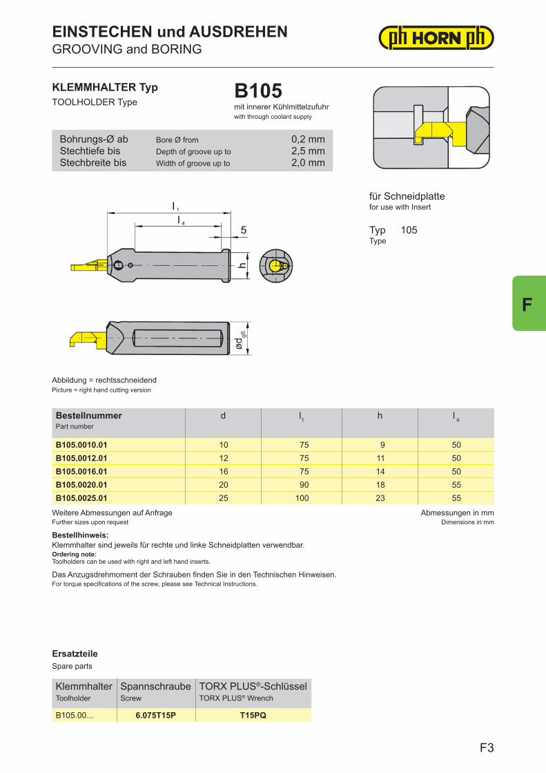
ErsatzteileSpare parts
KlemmhalterToolholder
SpannschraubeScrew
TORX PLUS®-SchlüsselTORX PLUS® Wrench
B105.00... 6.075T15P T15PQ
Weitere Abmessungen auf AnfrageFurther sizes upon request
Abmessungen in mmDimensions in mm
Bestellhinweis:Klemmhalter sind jeweils für rechte und linke Schneidplatten verwendbar.Ordering note:Toolholders can be used with right and left hand inserts.
Das Anzugsdrehmoment der Schrauben finden Sie in den Technischen Hinweisen.For torque specifications of the screw, please see Technical Instructions.
BestellnummerPart number
d l1 h l 4
B105.0010.01 10 75 9 50B105.0012.01 12 75 11 50B105.0016.01 16 75 14 50B105.0020.01 20 90 18 55B105.0025.01 25 100 23 55
KLEMMHALTER TypTOOLHOLDER Type
B105mit innerer Kühlmittelzufuhrwith through coolant supply
für Schneidplattefor use with Insert
TypType
105
Abbildung = rechtsschneidendPicture = right hand cutting version
Bohrungs-Ø abStechtiefe bisStechbreite bis
Bore Ø fromDepth of groove up toWidth of groove up to
0,2 mm2,5 mm2,0 mm
EINSTECHEN und AUSDREHENGROOVING and BORING
F3
F
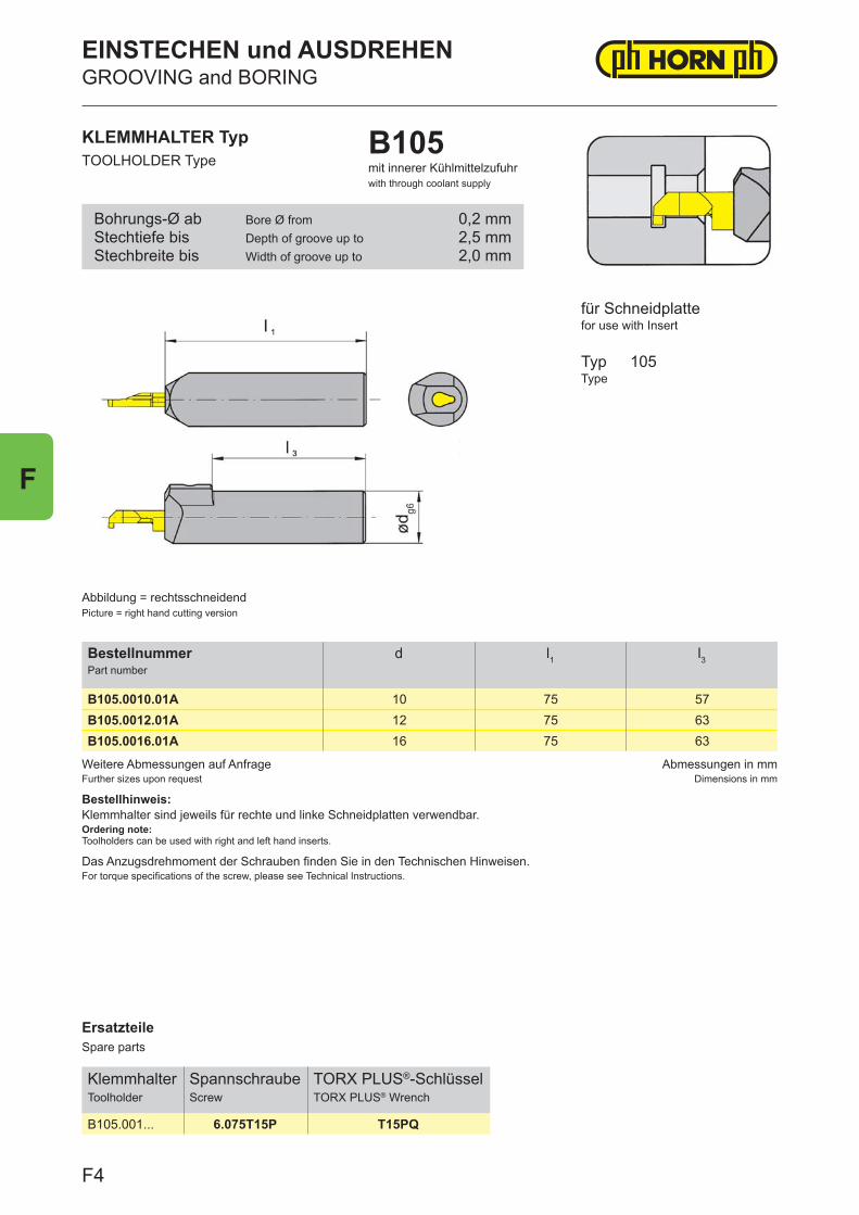
ErsatzteileSpare parts
KlemmhalterToolholder
SpannschraubeScrew
TORX PLUS®-SchlüsselTORX PLUS® Wrench
B105.001... 6.075T15P T15PQ
Weitere Abmessungen auf AnfrageFurther sizes upon request
Abmessungen in mmDimensions in mm
Bestellhinweis:Klemmhalter sind jeweils für rechte und linke Schneidplatten verwendbar.Ordering note:Toolholders can be used with right and left hand inserts.
Das Anzugsdrehmoment der Schrauben finden Sie in den Technischen Hinweisen.For torque specifications of the screw, please see Technical Instructions.
BestellnummerPart number
d l1 l3
B105.0010.01A 10 75 57B105.0012.01A 12 75 63B105.0016.01A 16 75 63
KLEMMHALTER TypTOOLHOLDER Type
B105mit innerer Kühlmittelzufuhrwith through coolant supply
Abbildung = rechtsschneidendPicture = right hand cutting version
für Schneidplattefor use with Insert
TypType
105
Bohrungs-Ø abStechtiefe bisStechbreite bis
Bore Ø fromDepth of groove up toWidth of groove up to
0,2 mm2,5 mm2,0 mm
EINSTECHEN und AUSDREHENGROOVING and BORING
F4
F
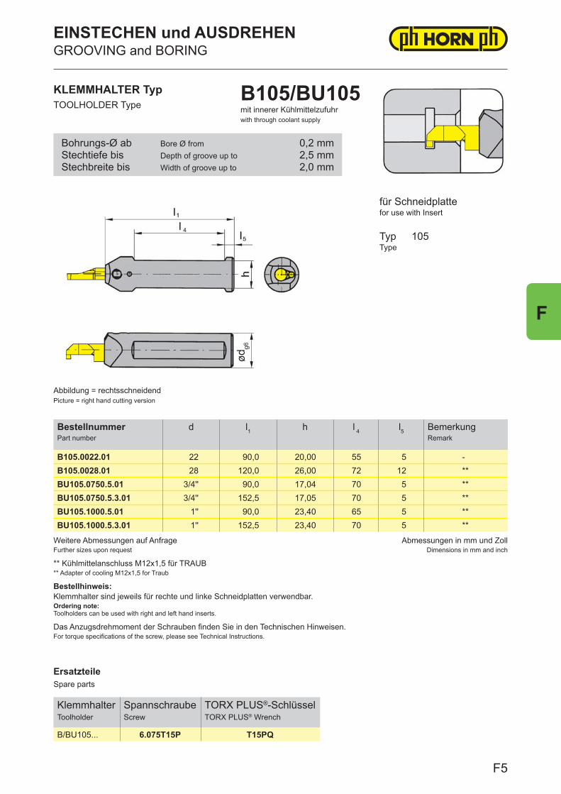
ErsatzteileSpare parts
KlemmhalterToolholder
SpannschraubeScrew
TORX PLUS®-SchlüsselTORX PLUS® Wrench
B/BU105... 6.075T15P T15PQ
Weitere Abmessungen auf AnfrageFurther sizes upon request
Abmessungen in mm und ZollDimensions in mm and inch
Das Anzugsdrehmoment der Schrauben finden Sie in den Technischen Hinweisen.For torque specifications of the screw, please see Technical Instructions.
** Kühlmittelanschluss M12x1,5 für TRAUB** Adapter of cooling M12x1,5 for Traub
Bestellhinweis:Klemmhalter sind jeweils für rechte und linke Schneidplatten verwendbar.Ordering note:Toolholders can be used with right and left hand inserts.
BestellnummerPart number
d l1 h l 4 l5 BemerkungRemark
B105.0022.01 22 90,0 20,00 55 5 -B105.0028.01 28 120,0 26,00 72 12 **BU105.0750.5.01 3/4'' 90,0 17,04 70 5 **BU105.0750.5.3.01 3/4'' 152,5 17,05 70 5 **BU105.1000.5.01 1'' 90,0 23,40 65 5 **BU105.1000.5.3.01 1'' 152,5 23,40 70 5 **
KLEMMHALTER TypTOOLHOLDER Type
B105/BU105mit innerer Kühlmittelzufuhrwith through coolant supply
für Schneidplattefor use with Insert
TypType
105
Abbildung = rechtsschneidendPicture = right hand cutting version
Bohrungs-Ø abStechtiefe bisStechbreite bis
Bore Ø fromDepth of groove up toWidth of groove up to
0,2 mm2,5 mm2,0 mm
EINSTECHEN und AUSDREHENGROOVING and BORING
F5
F
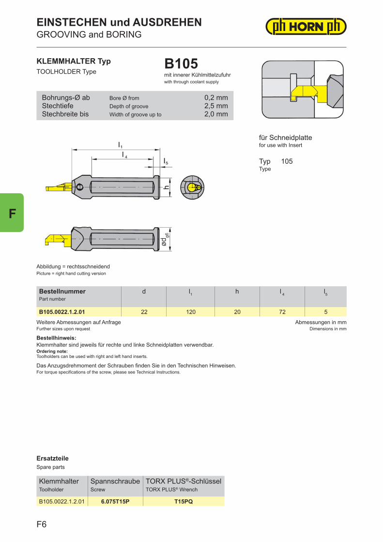
ErsatzteileSpare parts
KlemmhalterToolholder
SpannschraubeScrew
TORX PLUS®-SchlüsselTORX PLUS® Wrench
B105.0022.1.2.01 6.075T15P T15PQ
Weitere Abmessungen auf AnfrageFurther sizes upon request
Abmessungen in mmDimensions in mm
Das Anzugsdrehmoment der Schrauben finden Sie in den Technischen Hinweisen.For torque specifications of the screw, please see Technical Instructions.
Bestellhinweis:Klemmhalter sind jeweils für rechte und linke Schneidplatten verwendbar.Ordering note:Toolholders can be used with right and left hand inserts.
BestellnummerPart number
d l1 h l 4 l5
B105.0022.1.2.01 22 120 20 72 5
KLEMMHALTER TypTOOLHOLDER Type
B105mit innerer Kühlmittelzufuhrwith through coolant supply
Abbildung = rechtsschneidendPicture = right hand cutting version
für Schneidplattefor use with Insert
TypType
105
Bohrungs-Ø abStechtiefeStechbreite bis
Bore Ø fromDepth of grooveWidth of groove up to
0,2 mm2,5 mm2,0 mm
EINSTECHEN und AUSDREHENGROOVING and BORING
F6
F
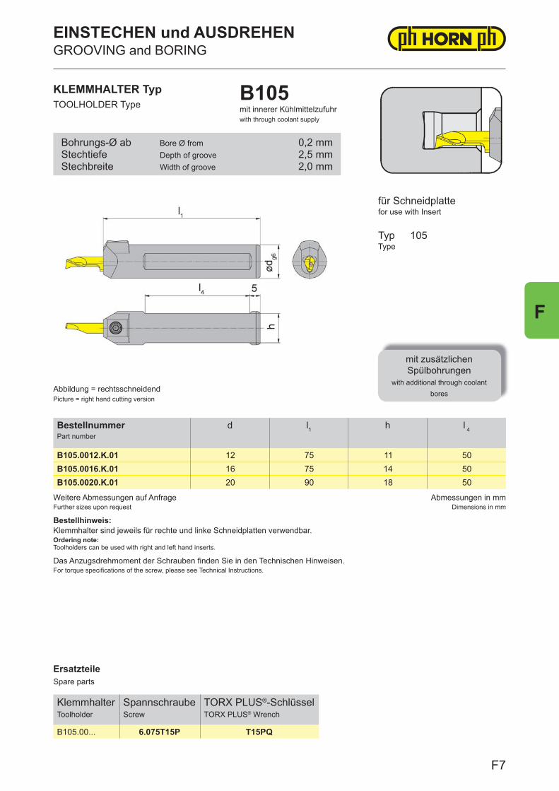
ErsatzteileSpare parts
KlemmhalterToolholder
SpannschraubeScrew
TORX PLUS®-SchlüsselTORX PLUS® Wrench
B105.00... 6.075T15P T15PQ
Weitere Abmessungen auf AnfrageFurther sizes upon request
Abmessungen in mmDimensions in mm
Bestellhinweis:Klemmhalter sind jeweils für rechte und linke Schneidplatten verwendbar.Ordering note:Toolholders can be used with right and left hand inserts.
Das Anzugsdrehmoment der Schrauben fi nden Sie in den Technischen Hinweisen.For torque specifi cations of the screw, please see Technical Instructions.
BestellnummerPart number
d l1 h l 4
B105.0012.K.01 12 75 11 50B105.0016.K.01 16 75 14 50B105.0020.K.01 20 90 18 50
KLEMMHALTER TypTOOLHOLDER Type
B105mit innerer Kühlmittelzufuhrwith through coolant supply
für Schneidplattefor use with Insert
TypType
mit zusätzlichenSpülbohrungen
with additional through coolant bores
105
Abbildung = rechtsschneidendPicture = right hand cutting version
Bohrungs-Ø abStechtiefeStechbreite
Bore Ø fromDepth of grooveWidth of groove
0,2 mm2,5 mm2,0 mm
EINSTECHEN und AUSDREHENGROOVING and BORING
F7
F
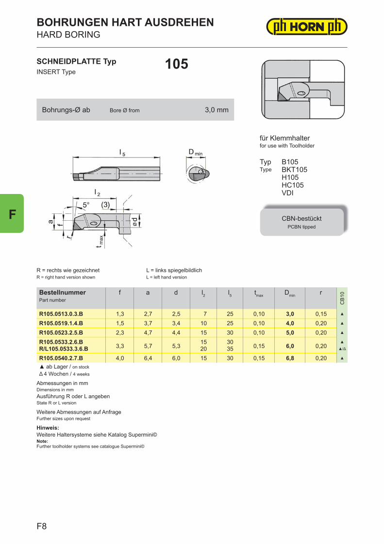
Abmessungen in mmDimensions in mm
Hinweis:Weitere Haltersysteme siehe Katalog Supermini©Note:Further toolholder systems see catalogue Supermini©
Ausführung R oder L angebenState R or L version
Weitere Abmessungen auf AnfrageFurther sizes upon request
BestellnummerPart number
f a d l2 l5 tmax Dmin r
CB
10
R105.0513.0.3.B 1,3 2,7 2,5 7 25 0,10 3,0 0,15 ▲
R105.0519.1.4.B 1,5 3,7 3,4 10 25 0,10 4,0 0,20 ▲
R105.0523.2.5.B 2,3 4,7 4,4 15 30 0,10 5,0 0,20 ▲
R105.0533.2.6.B3,3 5,7 5,3
15 300,15 6,0 0,20
▲
R/L105.0533.3.6.B 20 35 ▲/Δ
R105.0540.2.7.B 4,0 6,4 6,0 15 30 0,15 6,8 0,20 ▲
▲ ab Lager / on stockΔ 4 Wochen / 4 weeks
SCHNEIDPLATTE TypINSERT Type
105
BOHRUNGEN HART AUSDREHENHARD BORING
for use with Toolholder
TypType
CBN-bestücktPCBN tipped
B105BKT105H105HC105VDI
R = rechts wie gezeichnetR = right hand version shown
L = links spiegelbildlichL = left hand version
für Klemmhalter
Bohrungs-Ø ab Bore Ø from 3,0 mm
F8
F
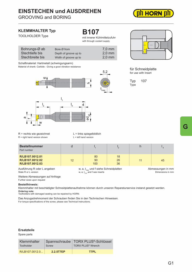
ErsatzteileSpare parts
KlemmhalterToolholder
SpannschraubeScrew
TORX PLUS®-SchlüsselTORX PLUS® Wrench
R/LB107.0012.0... 2.2.5T7EP T7PL
Ausführung R oder L angebenState R or L version
w, a, tmax und f siehe Schneidplattenw, a, tmax and f see inserts
Abmessungen in mmDimensions in mm
Das Anzugsdrehmoment der Schrauben finden Sie in den Technischen Hinweisen.For torque specifications of the screw, please see Technical Instructions.
Weitere Abmessungen auf AnfrageFurther sizes upon request
Bestellhinweis:Klemmhalter mit beschädigter Schneidplattenaufnahme können durch unseren Reparaturservice instand gesetzt werden.Ordering note:Toolholders with damaged seating can be repaired by HORN.
BestellnummerPart number
d l1 l2 h l 4
R/LB107.0012.0112
80 1811 45R/LB107.0012.02 90 26
R/LB107.0012.03 100 36
KLEMMHALTER TypTOOLHOLDER Type
B107mit innerer Kühlmittelzufuhrwith through coolant supply
für Schneidplattefor use with Insert
TypType
107
R = rechts wie gezeichnetR = right hand version shown
L = links spiegelbildlichL = left hand version
Schaftmaterial: Hartmetall (schwingungsarm)Material of shank: Carbide - Giving a good vibration resistance
Bohrungs-Ø abStechtiefe bisStechbreite bis
Bore Ø fromDepth of groove up toWidth of groove up to
7,0 mm2,0 mm2,0 mm
EINSTECHEN und AUSDREHENGROOVING and BORING
G1
G
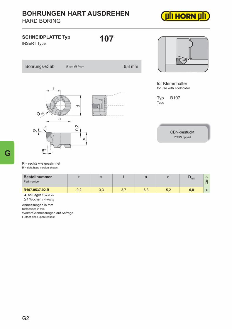
Abmessungen in mmDimensions in mmWeitere Abmessungen auf AnfrageFurther sizes upon request
BestellnummerPart number
r s f a d Dmin
CB
10
R107.0537.02.B 0,2 3,3 3,7 6,3 5,2 6,8 ▲
▲ ab Lager / on stockΔ 4 Wochen / 4 weeks
SCHNEIDPLATTE TypINSERT Type
107
BOHRUNGEN HART AUSDREHENHARD BORING
for use with Toolholder
TypType
CBN-bestücktPCBN tipped
B107
R = rechts wie gezeichnetR = right hand version shown
für Klemmhalter
Bohrungs-Ø ab Bore Ø from 6,8 mm
G2
G
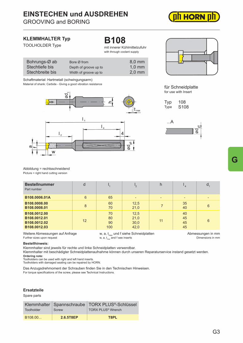
ErsatzteileSpare parts
KlemmhalterToolholder
SpannschraubeScrew
TORX PLUS®-SchlüsselTORX PLUS® Wrench
B108.00... 2.6.5T8EP T8PL
Weitere Abmessungen auf AnfrageFurther sizes upon request
w, a, tmax und f siehe Schneidplattenw, a, tmax and f see inserts
Abmessungen in mmDimensions in mm
Bestellhinweis:Klemmhalter sind jeweils für rechte und linke Schneidplatten verwendbar.Klemmhalter mit beschädigter Schneidplattenaufnahme können durch unseren Reparaturservice instand gesetzt werden.Ordering note:Toolholders can be used with right and left hand inserts.Toolholders with damaged seating can be repaired by HORN.
Das Anzugsdrehmoment der Schrauben finden Sie in den Technischen Hinweisen.For torque specifications of the screw, please see Technical Instructions.
BestellnummerPart number
d l1 l2 h l 4 d1
B108.0006.01A 6 65 - - - -B108.0008.00
860 12,5
735
6B108.0008.01 70 21,0 40B108.0012.00
12
70 12,5
11
40
6B108.0012.01 80 21,0 45B108.0012.02 90 30,0 45B108.0012.03 100 42,0 45
KLEMMHALTER TypTOOLHOLDER Type
B108mit innerer Kühlmittelzufuhrwith through coolant supply
für Schneidplattefor use with Insert
TypType
108S108
Abbildung = rechtsschneidendPicture = right hand cutting version
Schaftmaterial: Hartmetall (schwingungsarm)Material of shank: Carbide - Giving a good vibration resistance
Bohrungs-Ø abStechtiefe bisStechbreite bis
Bore Ø fromDepth of groove up toWidth of groove up to
8,0 mm1,0 mm2,0 mm
EINSTECHEN und AUSDREHENGROOVING and BORING
G3
G

ErsatzteileSpare parts
KlemmhalterToolholder
SpannschraubeScrew
TORX PLUS®-SchlüsselTORX PLUS® Wrench
B108.0012.0... 2.6.5T8EP T8PL
Weitere Abmessungen auf AnfrageFurther sizes upon request
w, a, tmax und f siehe Schneidplattenw, a, tmax and f see inserts
Abmessungen in mmDimensions in mm
Bestellhinweis:Klemmhalter sind jeweils für rechte und linke Schneidplatten verwendbar.Klemmhalter mit beschädigter Schneidplattenaufnahme können durch unseren Reparaturservice instand gesetzt werden.Ordering note:Toolholders can be used with right and left hand inserts.Toolholders with damaged seating can be repaired by HORN.
Das Anzugsdrehmoment der Schrauben fi nden Sie in den Technischen Hinweisen.For torque specifi cations of the screw, please see Technical Instructions.
BestellnummerPart number
d l1 l2 d1
B108.0012.00S
12
48,7 12,5
6B108.0012.01S 56,7 21,0B108.0012.02S 65,7 30,0B108.0012.03S 77,7 42,0
Schaftmaterial: Hartmetall (schwingungsarm)Material of shank: Carbide - Giving a good vibration resistance
KLEMMHALTER TypTOOLHOLDER Type
B108mit innerer Kühlmittelzufuhrwith through coolant supply
Abbildung = rechtsschneidendPicture = right hand cutting version
für Schneidplattefor use with Insert
TypType
zum lageorientiertenSchrumpfen
S = Lageorientierungfor shrinkage location
S = orientation
108S108
Bohrungs-Ø abStechtiefe bisStechbreite bis
Bore Ø fromDepth of groove up toWidth of groove up to
8,0 mm1,0 mm2,0 mm
EINSTECHEN und AUSDREHENGROOVING and BORING
G4
G
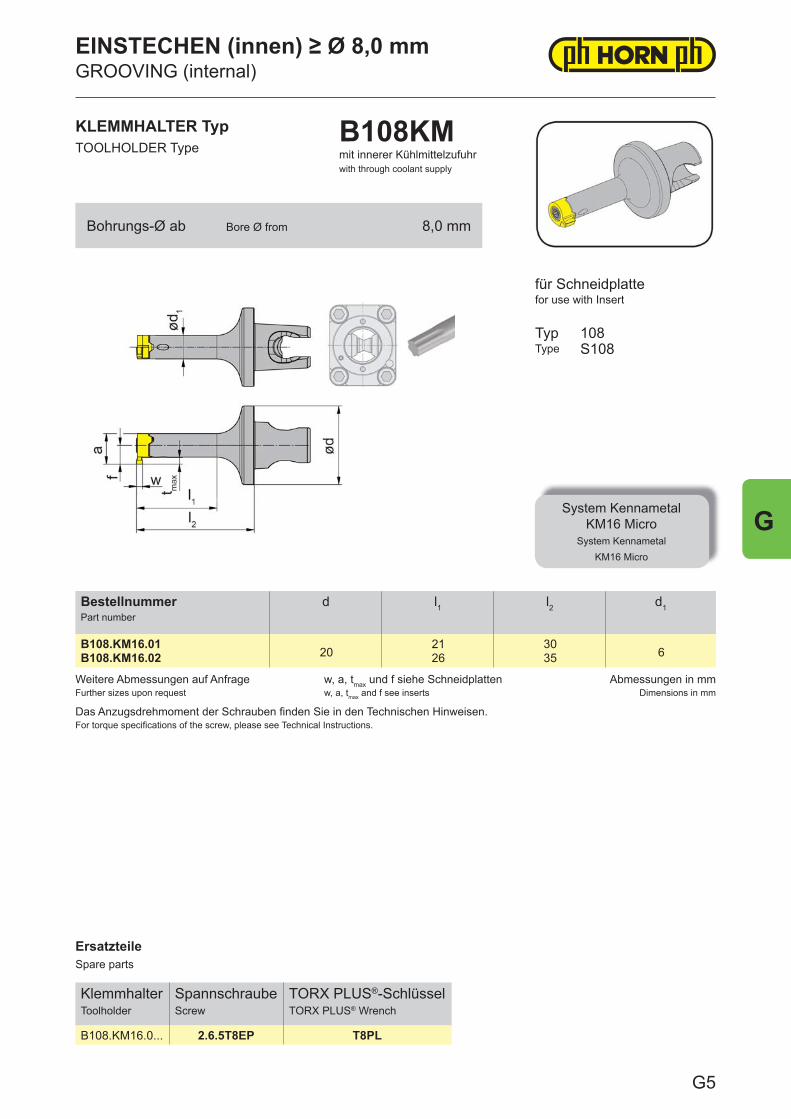
ErsatzteileSpare parts
KlemmhalterToolholder
SpannschraubeScrew
TORX PLUS®-SchlüsselTORX PLUS® Wrench
B108.KM16.0... 2.6.5T8EP T8PL
Weitere Abmessungen auf AnfrageFurther sizes upon request
w, a, tmax und f siehe Schneidplattenw, a, tmax and f see inserts
Abmessungen in mmDimensions in mm
Das Anzugsdrehmoment der Schrauben fi nden Sie in den Technischen Hinweisen.For torque specifi cations of the screw, please see Technical Instructions.
BestellnummerPart number
d l1 l2 d1
B108.KM16.0120
21 306B108.KM16.02 26 35
KLEMMHALTER TypTOOLHOLDER Type
B108KMmit innerer Kühlmittelzufuhrwith through coolant supply
für Schneidplattefor use with Insert
TypType
System KennametalKM16 Micro
System KennametalKM16 Micro
108S108
Bohrungs-Ø ab Bore Ø from 8,0 mm
EINSTECHEN (innen) ≥ Ø 8,0 mmGROOVING (internal)
G5
G
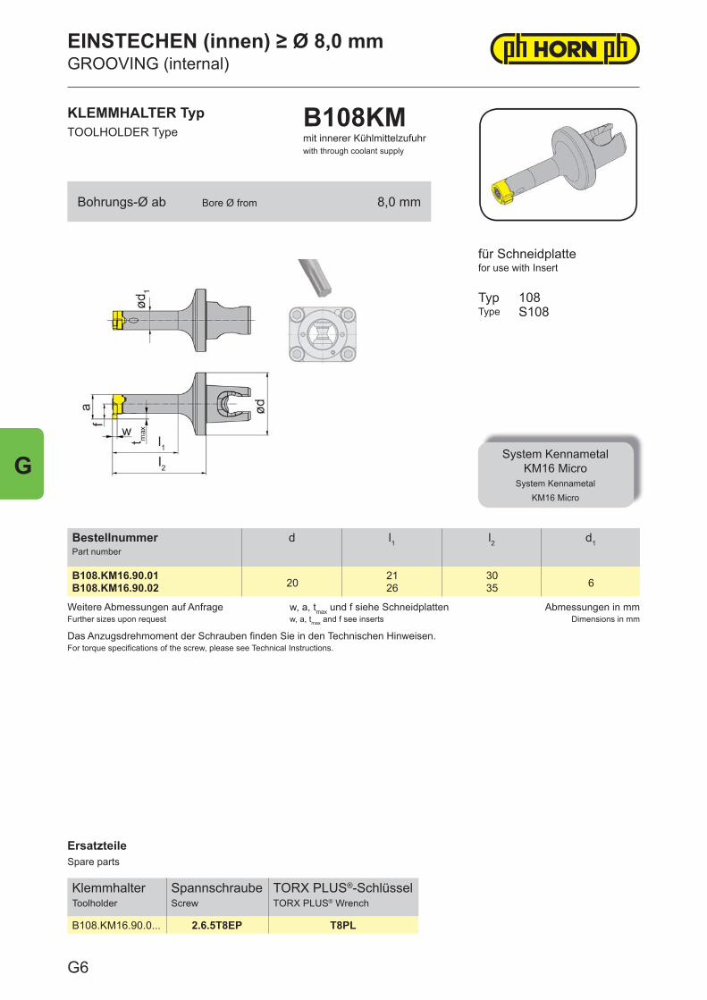
ErsatzteileSpare parts
KlemmhalterToolholder
SpannschraubeScrew
TORX PLUS®-SchlüsselTORX PLUS® Wrench
B108.KM16.90.0... 2.6.5T8EP T8PL
Weitere Abmessungen auf AnfrageFurther sizes upon request
w, a, tmax und f siehe Schneidplattenw, a, tmax and f see inserts
Abmessungen in mmDimensions in mm
Das Anzugsdrehmoment der Schrauben fi nden Sie in den Technischen Hinweisen.For torque specifi cations of the screw, please see Technical Instructions.
BestellnummerPart number
d l1 l2 d1
B108.KM16.90.0120
21 306B108.KM16.90.02 26 35
KLEMMHALTER TypTOOLHOLDER Type
B108KMmit innerer Kühlmittelzufuhrwith through coolant supply
für Schneidplattefor use with Insert
TypType
System KennametalKM16 Micro
System KennametalKM16 Micro
108S108
Bohrungs-Ø ab Bore Ø from 8,0 mm
EINSTECHEN (innen) ≥ Ø 8,0 mmGROOVING (internal)
G6
G
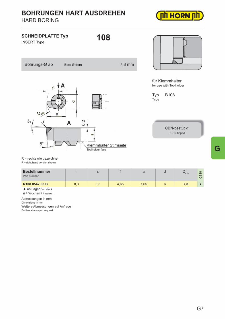
Abmessungen in mmDimensions in mmWeitere Abmessungen auf AnfrageFurther sizes upon request
BestellnummerPart number
r s f a d Dmin
CB
10
R108.0547.03.B 0,3 3,5 4,65 7,65 6 7,8 ▲
▲ ab Lager / on stockΔ 4 Wochen / 4 weeks
SCHNEIDPLATTE TypINSERT Type
108
BOHRUNGEN HART AUSDREHENHARD BORING
for use with Toolholder
TypType
CBN-bestücktPCBN tipped
B108
R = rechts wie gezeichnetR = right hand version shown
für Klemmhalter
Bohrungs-Ø ab Bore Ø from 7,8 mm
G7
G
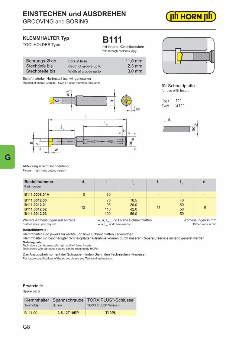
ErsatzteileSpare parts
KlemmhalterToolholder
SpannschraubeScrew
TORX PLUS®-SchlüsselTORX PLUS® Wrench
B111.00... 3.5.12T10EP T10PL
Weitere Abmessungen auf AnfrageFurther sizes upon request
w, a, tmax und f siehe Schneidplattenw, a, tmax and f see inserts
Abmessungen in mmDimensions in mm
Bestellhinweis:Klemmhalter sind jeweils für rechte und linke Schneidplatten verwendbar.Klemmhalter mit beschädigter Schneidplattenaufnahme können durch unseren Reparaturservice instand gesetzt werden.Ordering note:Toolholders can be used with right and left hand inserts.Toolholders with damaged seating can be repaired by HORN.
Das Anzugsdrehmoment der Schrauben finden Sie in den Technischen Hinweisen.For torque specifications of the screw, please see Technical Instructions.
BestellnummerPart number
d l1 l2 h l 4 d1
B111.0008.01A 8 80 - - - -B111.0012.00
12
75 16,5
11
40
8B111.0012.01 95 29,0 50B111.0012.02 110 42,0 50B111.0012.03 120 56,0 50
Schaftmaterial: Hartmetall (schwingungsarm)Material of shank: Carbide - Giving a good vibration resistance
KLEMMHALTER TypTOOLHOLDER Type
B111mit innerer Kühlmittelzufuhrwith through coolant supply
Abbildung = rechtsschneidendPicture = right hand cutting version
für Schneidplattefor use with Insert
TypType
111S111
Bohrungs-Ø abStechtiefe bisStechbreite bis
Bore Ø fromDepth of groove up toWidth of groove up to
11,0 mm2,3 mm3,0 mm
EINSTECHEN und AUSDREHENGROOVING and BORING
G8
G
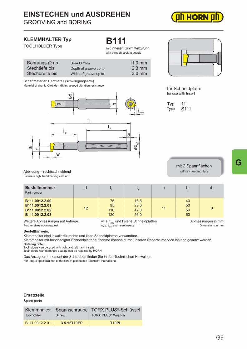
ErsatzteileSpare parts
KlemmhalterToolholder
SpannschraubeScrew
TORX PLUS®-SchlüsselTORX PLUS® Wrench
B111.0012.2.0... 3.5.12T10EP T10PL
Weitere Abmessungen auf AnfrageFurther sizes upon request
w, a, tmax und f siehe Schneidplattenw, a, tmax and f see inserts
Abmessungen in mmDimensions in mm
Bestellhinweis:Klemmhalter sind jeweils für rechte und linke Schneidplatten verwendbar.Klemmhalter mit beschädigter Schneidplattenaufnahme können durch unseren Reparaturservice instand gesetzt werden.Ordering note:Toolholders can be used with right and left hand inserts.Toolholders with damaged seating can be repaired by HORN.
Das Anzugsdrehmoment der Schrauben fi nden Sie in den Technischen Hinweisen.For torque specifi cations of the screw, please see Technical Instructions.
BestellnummerPart number
d l1 l2 h l 4 d1
B111.0012.2.00
12
75 16,5
11
40
8B111.0012.2.01 95 29,0 50B111.0012.2.02 110 42,0 50B111.0012.2.03 120 56,0 50
KLEMMHALTER TypTOOLHOLDER Type
B111mit innerer Kühlmittelzufuhrwith through coolant supply
für Schneidplattefor use with Insert
TypType
mit 2 Spannfl ächenwith 2 clamping fl ats
111S111
Abbildung = rechtsschneidendPicture = right hand cutting version
Schaftmaterial: Hartmetall (schwingungsarm)Material of shank: Carbide - Giving a good vibration resistance
Bohrungs-Ø abStechtiefe bisStechbreite bis
Bore Ø fromDepth of groove up toWidth of groove up to
11,0 mm2,3 mm3,0 mm
EINSTECHEN und AUSDREHENGROOVING and BORING
G9
G
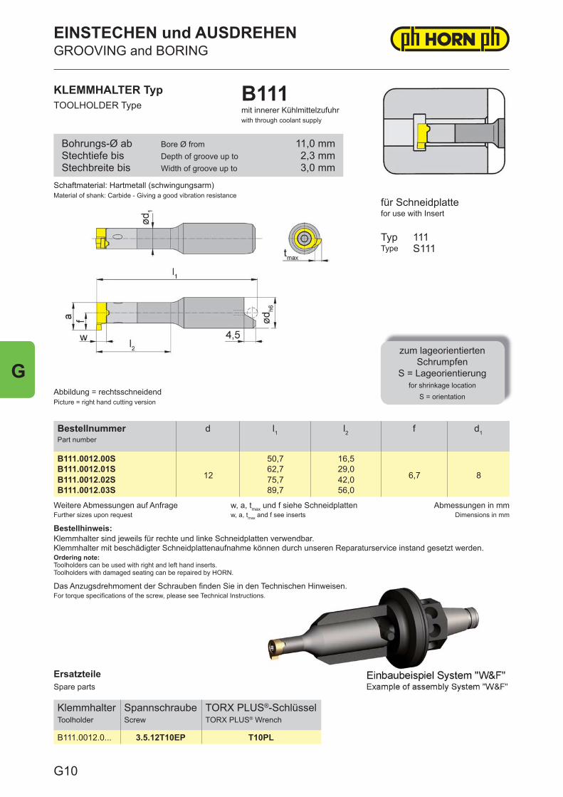
ErsatzteileSpare parts
KlemmhalterToolholder
SpannschraubeScrew
TORX PLUS®-SchlüsselTORX PLUS® Wrench
B111.0012.0... 3.5.12T10EP T10PL
Weitere Abmessungen auf AnfrageFurther sizes upon request
w, a, tmax und f siehe Schneidplattenw, a, tmax and f see inserts
Abmessungen in mmDimensions in mm
Bestellhinweis:Klemmhalter sind jeweils für rechte und linke Schneidplatten verwendbar.Klemmhalter mit beschädigter Schneidplattenaufnahme können durch unseren Reparaturservice instand gesetzt werden.Ordering note:Toolholders can be used with right and left hand inserts.Toolholders with damaged seating can be repaired by HORN.
Das Anzugsdrehmoment der Schrauben fi nden Sie in den Technischen Hinweisen.For torque specifi cations of the screw, please see Technical Instructions.
BestellnummerPart number
d l1 l2 f d1
B111.0012.00S
12
50,7 16,5
6,7 8B111.0012.01S 62,7 29,0B111.0012.02S 75,7 42,0B111.0012.03S 89,7 56,0
Schaftmaterial: Hartmetall (schwingungsarm)Material of shank: Carbide - Giving a good vibration resistance
KLEMMHALTER TypTOOLHOLDER Type
B111mit innerer Kühlmittelzufuhrwith through coolant supply
Abbildung = rechtsschneidendPicture = right hand cutting version
für Schneidplattefor use with Insert
TypType
zum lageorientiertenSchrumpfen
S = Lageorientierungfor shrinkage location
S = orientation
111S111
Bohrungs-Ø abStechtiefe bisStechbreite bis
Bore Ø fromDepth of groove up toWidth of groove up to
11,0 mm2,3 mm3,0 mm
EINSTECHEN und AUSDREHENGROOVING and BORING
G10
G
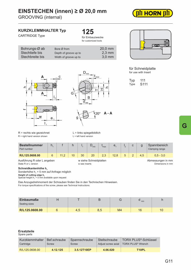
Ausführung R oder L angebenState R or L version
w siehe Schneidplattenw see inserts
Abmessungen in mmDimensions in mm
Schneidkantenhöhe h1Sonderhöhe h1 = 5 mm auf Anfrage möglichHeight of cutting edge h1Special height h1 = 5 mm available upon request
Das Anzugsdrehmoment der Schrauben finden Sie in den Technischen Hinweisen.For torque specifications of the screw, please see Technical Instructions.
BestellnummerPart number
h1 f h l1 Dmin tmax e1 l2 c g SpannbereichClamping range
R/L125.0608.00 6 11,2 10 30 20 2,3 12,8 5 2 4,5 0,5 - 3,0
ErsatzteileSpare parts
KurzklemmhalterCartridge
Bef.schraubeScrew
SpannschraubeScrew
StellschraubeAdjust screw axial
TORX PLUS®-SchlüsselTORX PLUS® Wrench
R/L125.0608.00 4.12.125 3.5.12T10EP 4.06.020 T10PL
KURZKLEMMHALTER TypCARTRIDGE Type
125für Einbauzweckefor customized tools
für Schneidplattefor use with Insert
TypType
111S111
R = rechts wie gezeichnetR = right hand version shown
L = links spiegelbildlichL = left hand version
Bohrungs-Ø abStechtiefe bisStechbreite bis
Bore Ø fromDepth of groove up toWidth of groove up to
20,0 mm2,3 mm3,0 mm
EINSTECHEN (innen) ≥ Ø 20,0 mmGROOVING (internal)
G11
G
EinbaumaßeSeating sizes
H T B G d min h
R/L125.0608.00 6 4,5 8,5 M4 16 10
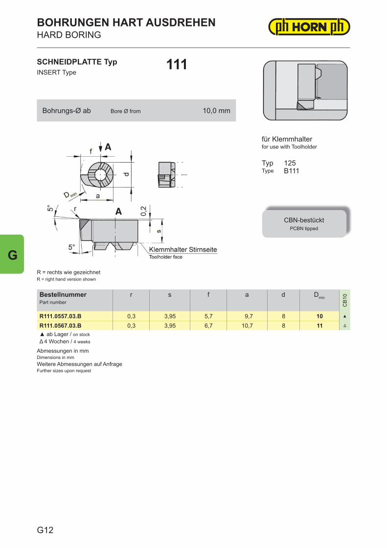
Abmessungen in mmDimensions in mmWeitere Abmessungen auf AnfrageFurther sizes upon request
BestellnummerPart number
r s f a d Dmin
CB
10
R111.0557.03.B 0,3 3,95 5,7 9,7 8 10 ▲
R111.0567.03.B 0,3 3,95 6,7 10,7 8 11 Δ
▲ ab Lager / on stockΔ 4 Wochen / 4 weeks
SCHNEIDPLATTE TypINSERT Type
111
BOHRUNGEN HART AUSDREHENHARD BORING
for use with Toolholder
TypType
CBN-bestücktPCBN tipped
125B111
R = rechts wie gezeichnetR = right hand version shown
für Klemmhalter
Bohrungs-Ø ab Bore Ø from 10,0 mm
G12
G
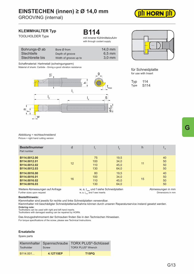
ErsatzteileSpare parts
KlemmhalterToolholder
SpannschraubeScrew
TORX PLUS®-SchlüsselTORX PLUS® Wrench
B114.001... 4.12T15EP T15PQ
Weitere Abmessungen auf AnfrageFurther sizes upon request
w, a, tmax und f siehe Schneidplattenw, a, tmax and f see inserts
Abmessungen in mmDimensions in mm
Bestellhinweis:Klemmhalter sind jeweils für rechte und linke Schneidplatten verwendbar.Klemmhalter mit beschädigter Schneidplattenaufnahme können durch unseren Reparaturservice instand gesetzt werden.Ordering note:Toolholders can be used with right and left hand inserts.Toolholders with damaged seating can be repaired by HORN.
Das Anzugsdrehmoment der Schrauben finden Sie in den Technischen Hinweisen.For torque specifications of the screw, please see Technical Instructions.
BestellnummerPart number
d l1 l2 h l 4
B114.0012.00
12
75 19,5
11
40B114.0012.01 100 34,0 50B114.0012.02 110 45,0 50B114.0012.03 130 64,0 50B114.0016.00
16
80 19,5
15
40B114.0016.01 100 34,0 50B114.0016.02 110 45,0 50B114.0016.03 130 64,0 50
KLEMMHALTER TypTOOLHOLDER Type
B114mit innerer Kühlmittelzufuhrwith through coolant supply
für Schneidplattefor use with Insert
TypType
114S114
Abbildung = rechtsschneidendPicture = right hand cutting version
Schaftmaterial: Hartmetall (schwingungsarm)Material of shank: Carbide - Giving a good vibration resistance
Bohrungs-Ø abStechtiefeStechbreite bis
Bore Ø fromDepth of grooveWidth of groove up to
14,0 mm6,5 mm3,0 mm
EINSTECHEN (innen) ≥ Ø 14,0 mmGROOVING (internal)
G13
G
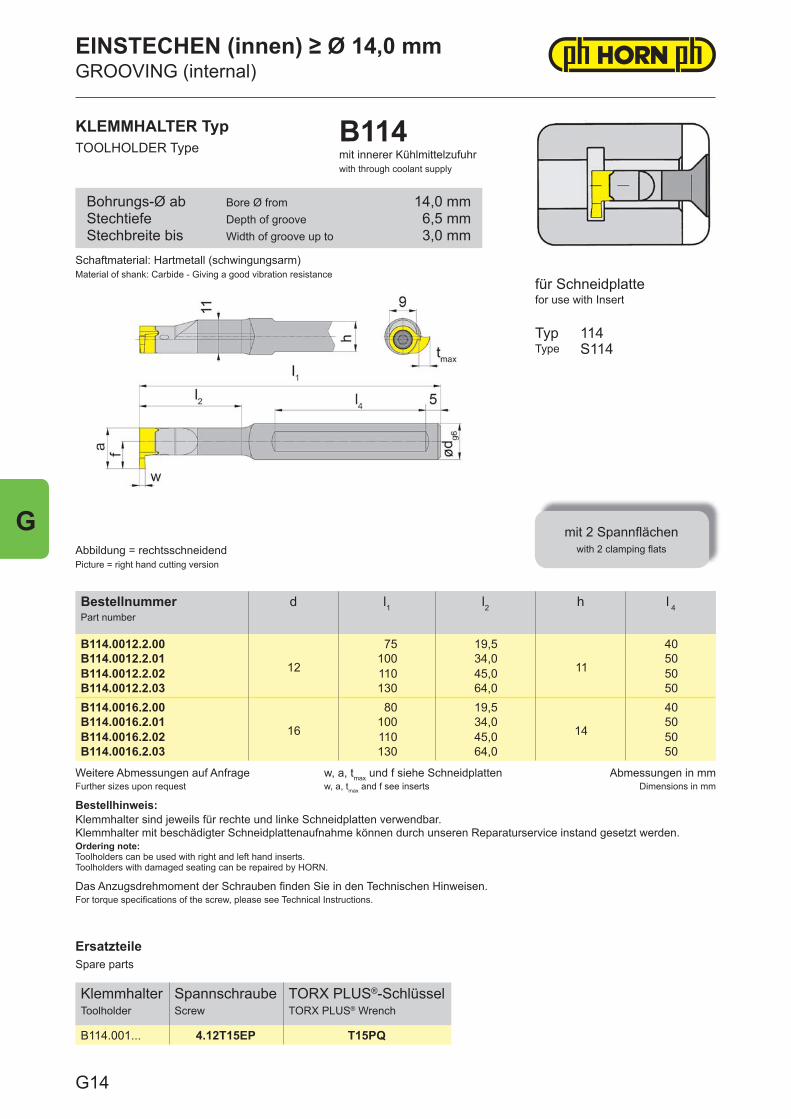
ErsatzteileSpare parts
KlemmhalterToolholder
SpannschraubeScrew
TORX PLUS®-SchlüsselTORX PLUS® Wrench
B114.001... 4.12T15EP T15PQ
Weitere Abmessungen auf AnfrageFurther sizes upon request
w, a, tmax und f siehe Schneidplattenw, a, tmax and f see inserts
Abmessungen in mmDimensions in mm
Bestellhinweis:Klemmhalter sind jeweils für rechte und linke Schneidplatten verwendbar.Klemmhalter mit beschädigter Schneidplattenaufnahme können durch unseren Reparaturservice instand gesetzt werden.Ordering note:Toolholders can be used with right and left hand inserts.Toolholders with damaged seating can be repaired by HORN.
Das Anzugsdrehmoment der Schrauben fi nden Sie in den Technischen Hinweisen.For torque specifi cations of the screw, please see Technical Instructions.
BestellnummerPart number
d l1 l2 h l 4
B114.0012.2.00
12
75 19,5
11
40B114.0012.2.01 100 34,0 50B114.0012.2.02 110 45,0 50B114.0012.2.03 130 64,0 50B114.0016.2.00
16
80 19,5
14
40B114.0016.2.01 100 34,0 50B114.0016.2.02 110 45,0 50B114.0016.2.03 130 64,0 50
Schaftmaterial: Hartmetall (schwingungsarm)Material of shank: Carbide - Giving a good vibration resistance
KLEMMHALTER TypTOOLHOLDER Type
B114mit innerer Kühlmittelzufuhrwith through coolant supply
Abbildung = rechtsschneidendPicture = right hand cutting version
für Schneidplattefor use with Insert
TypType
mit 2 Spannfl ächenwith 2 clamping fl ats
114S114
Bohrungs-Ø abStechtiefeStechbreite bis
Bore Ø fromDepth of grooveWidth of groove up to
14,0 mm6,5 mm3,0 mm
EINSTECHEN (innen) ≥ Ø 14,0 mmGROOVING (internal)
G14
G
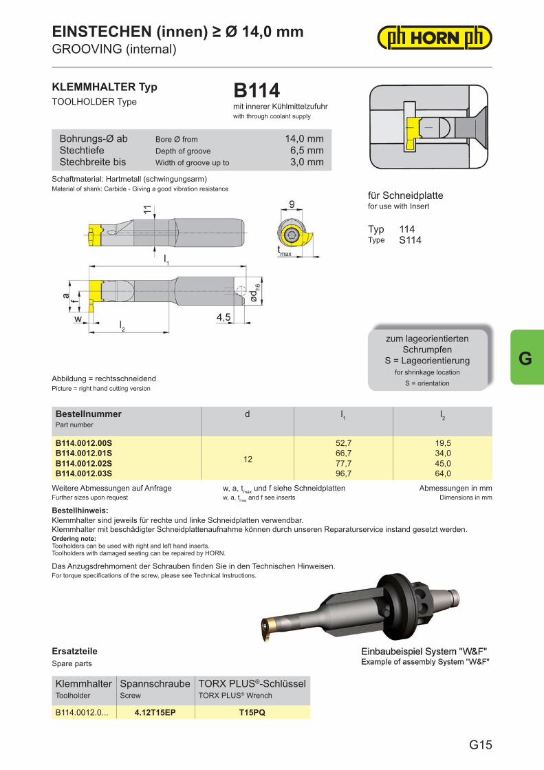
ErsatzteileSpare parts
KlemmhalterToolholder
SpannschraubeScrew
TORX PLUS®-SchlüsselTORX PLUS® Wrench
B114.0012.0... 4.12T15EP T15PQ
Weitere Abmessungen auf AnfrageFurther sizes upon request
w, a, tmax und f siehe Schneidplattenw, a, tmax and f see inserts
Abmessungen in mmDimensions in mm
Bestellhinweis:Klemmhalter sind jeweils für rechte und linke Schneidplatten verwendbar.Klemmhalter mit beschädigter Schneidplattenaufnahme können durch unseren Reparaturservice instand gesetzt werden.Ordering note:Toolholders can be used with right and left hand inserts.Toolholders with damaged seating can be repaired by HORN.
Das Anzugsdrehmoment der Schrauben fi nden Sie in den Technischen Hinweisen.For torque specifi cations of the screw, please see Technical Instructions.
BestellnummerPart number
d l1 l2
B114.0012.00S
12
52,7 19,5B114.0012.01S 66,7 34,0B114.0012.02S 77,7 45,0B114.0012.03S 96,7 64,0
KLEMMHALTER TypTOOLHOLDER Type
B114mit innerer Kühlmittelzufuhrwith through coolant supply
für Schneidplattefor use with Insert
TypType
zum lageorientiertenSchrumpfen
S = Lageorientierungfor shrinkage location
S = orientation
114S114
Abbildung = rechtsschneidendPicture = right hand cutting version
Schaftmaterial: Hartmetall (schwingungsarm)Material of shank: Carbide - Giving a good vibration resistance
Bohrungs-Ø abStechtiefeStechbreite bis
Bore Ø fromDepth of grooveWidth of groove up to
14,0 mm6,5 mm3,0 mm
EINSTECHEN (innen) ≥ Ø 14,0 mmGROOVING (internal)
G15
G
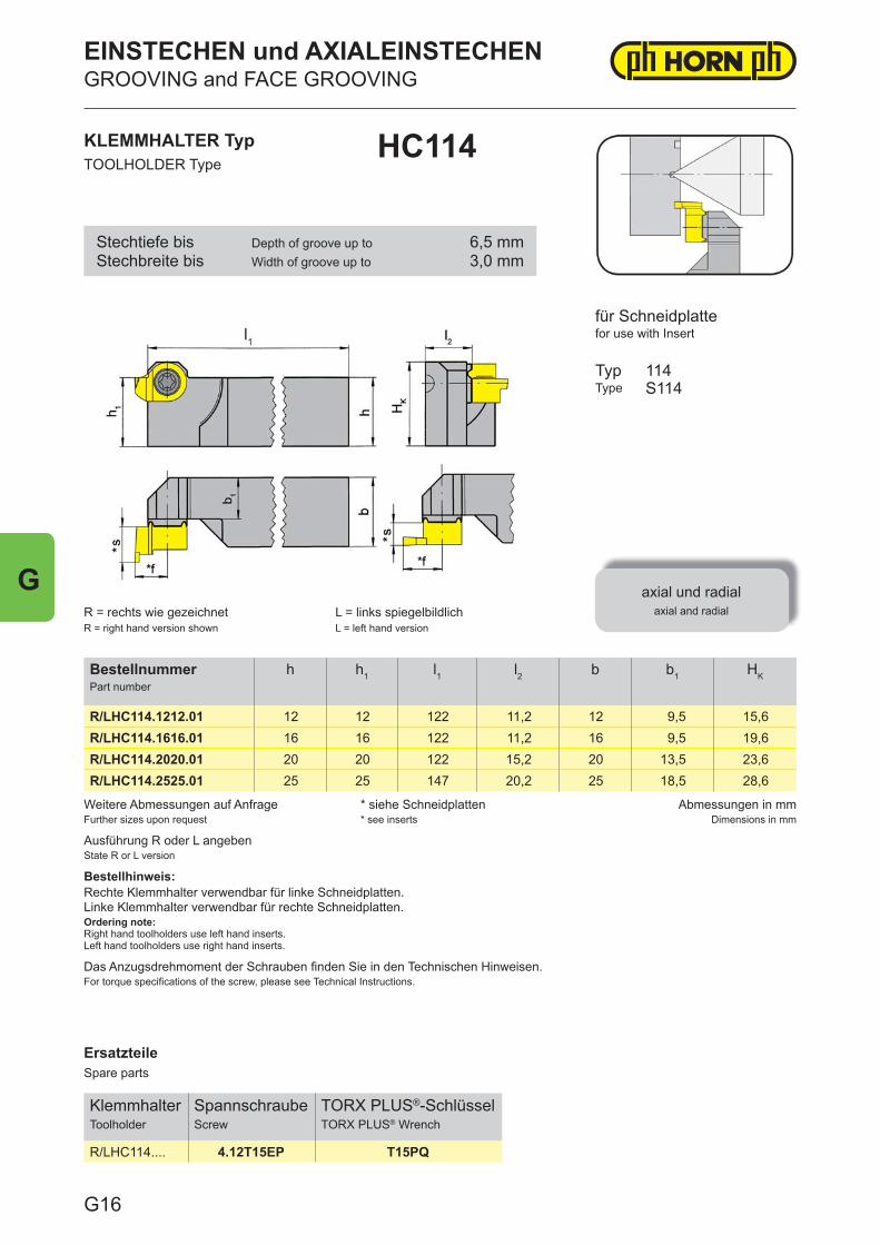
ErsatzteileSpare parts
KlemmhalterToolholder
SpannschraubeScrew
TORX PLUS®-SchlüsselTORX PLUS® Wrench
R/LHC114.... 4.12T15EP T15PQ
Weitere Abmessungen auf AnfrageFurther sizes upon request
* siehe Schneidplatten* see inserts
Abmessungen in mmDimensions in mm
Das Anzugsdrehmoment der Schrauben fi nden Sie in den Technischen Hinweisen.For torque specifi cations of the screw, please see Technical Instructions.
Ausführung R oder L angebenState R or L version
Bestellhinweis:Rechte Klemmhalter verwendbar für linke Schneidplatten.Linke Klemmhalter verwendbar für rechte Schneidplatten.Ordering note:Right hand toolholders use left hand inserts.Left hand toolholders use right hand inserts.
BestellnummerPart number
h h1 l1 l2 b b1 HK
R/LHC114.1212.01 12 12 122 11,2 12 9,5 15,6R/LHC114.1616.01 16 16 122 11,2 16 9,5 19,6R/LHC114.2020.01 20 20 122 15,2 20 13,5 23,6R/LHC114.2525.01 25 25 147 20,2 25 18,5 28,6
KLEMMHALTER TypTOOLHOLDER Type
HC114
R = rechts wie gezeichnetR = right hand version shown
L = links spiegelbildlichL = left hand version
für Schneidplattefor use with Insert
TypType
axial und radialaxial and radial
114S114
Stechtiefe bisStechbreite bis
Depth of groove up toWidth of groove up to
6,5 mm3,0 mm
EINSTECHEN und AXIALEINSTECHENGROOVING and FACE GROOVING
G16
G
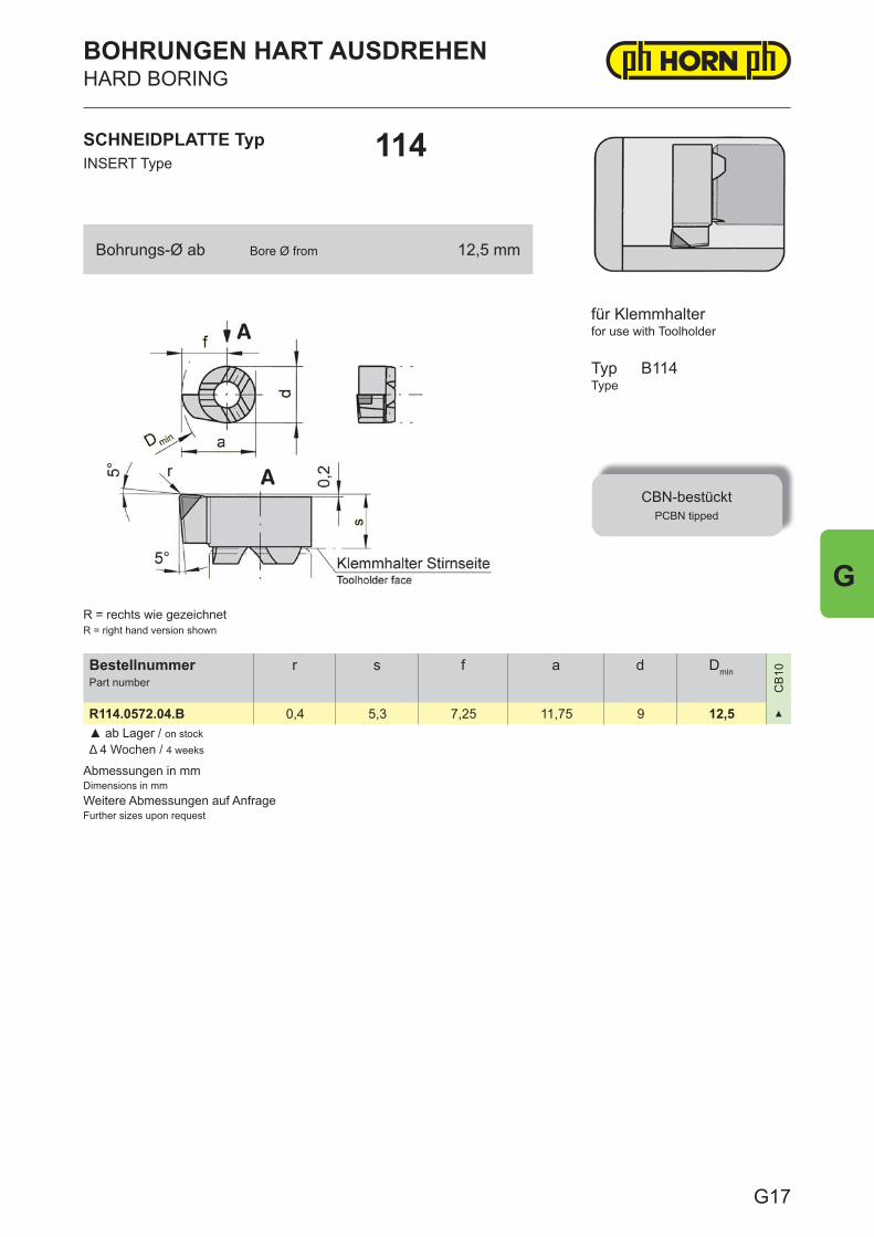
Abmessungen in mmDimensions in mmWeitere Abmessungen auf AnfrageFurther sizes upon request
BestellnummerPart number
r s f a d Dmin
CB
10
R114.0572.04.B 0,4 5,3 7,25 11,75 9 12,5 ▲
▲ ab Lager / on stockΔ 4 Wochen / 4 weeks
SCHNEIDPLATTE TypINSERT Type
114
BOHRUNGEN HART AUSDREHENHARD BORING
for use with Toolholder
TypType
CBN-bestücktPCBN tipped
B114
R = rechts wie gezeichnetR = right hand version shown
für Klemmhalter
Bohrungs-Ø ab Bore Ø from 12,5 mm
G17
G
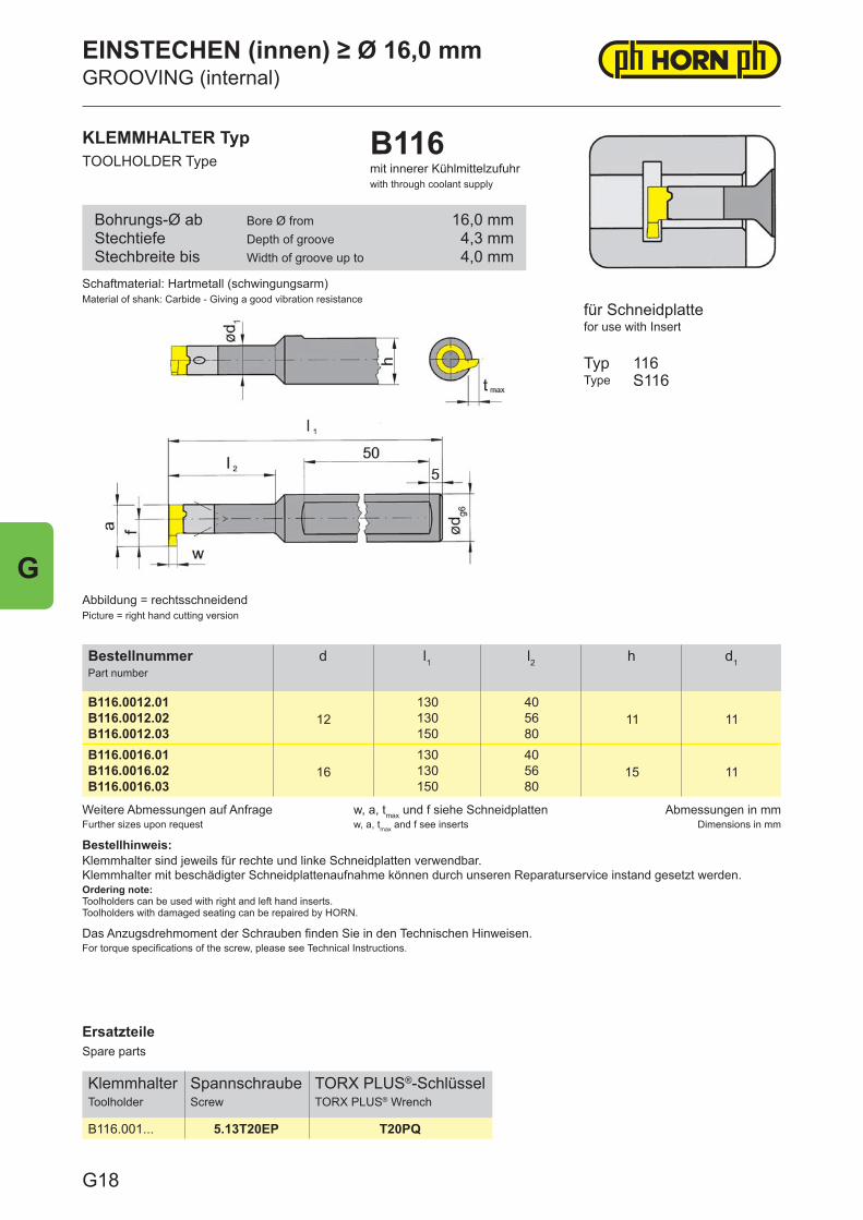
ErsatzteileSpare parts
KlemmhalterToolholder
SpannschraubeScrew
TORX PLUS®-SchlüsselTORX PLUS® Wrench
B116.001... 5.13T20EP T20PQ
Weitere Abmessungen auf AnfrageFurther sizes upon request
w, a, tmax und f siehe Schneidplattenw, a, tmax and f see inserts
Abmessungen in mmDimensions in mm
Bestellhinweis:Klemmhalter sind jeweils für rechte und linke Schneidplatten verwendbar.Klemmhalter mit beschädigter Schneidplattenaufnahme können durch unseren Reparaturservice instand gesetzt werden.Ordering note:Toolholders can be used with right and left hand inserts.Toolholders with damaged seating can be repaired by HORN.
Das Anzugsdrehmoment der Schrauben finden Sie in den Technischen Hinweisen.For torque specifications of the screw, please see Technical Instructions.
BestellnummerPart number
d l1 l2 h d1
B116.0012.0112
130 4011 11B116.0012.02 130 56
B116.0012.03 150 80B116.0016.01
16130 40
15 11B116.0016.02 130 56B116.0016.03 150 80
KLEMMHALTER TypTOOLHOLDER Type
B116mit innerer Kühlmittelzufuhrwith through coolant supply
für Schneidplattefor use with Insert
TypType
116S116
Abbildung = rechtsschneidendPicture = right hand cutting version
Schaftmaterial: Hartmetall (schwingungsarm)Material of shank: Carbide - Giving a good vibration resistance
Bohrungs-Ø abStechtiefeStechbreite bis
Bore Ø fromDepth of grooveWidth of groove up to
16,0 mm4,3 mm4,0 mm
EINSTECHEN (innen) ≥ Ø 16,0 mmGROOVING (internal)
G18
G
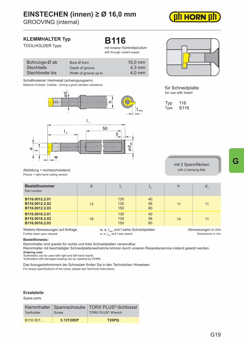
ErsatzteileSpare parts
KlemmhalterToolholder
SpannschraubeScrew
TORX PLUS®-SchlüsselTORX PLUS® Wrench
B116.001... 5.13T20EP T20PQ
Weitere Abmessungen auf AnfrageFurther sizes upon request
w, a, tmax und f siehe Schneidplattenw, a, tmax and f see inserts
Abmessungen in mmDimensions in mm
Bestellhinweis:Klemmhalter sind jeweils für rechte und linke Schneidplatten verwendbar.Klemmhalter mit beschädigter Schneidplattenaufnahme können durch unseren Reparaturservice instand gesetzt werden.Ordering note:Toolholders can be used with right and left hand inserts.Toolholders with damaged seating can be repaired by HORN.
Das Anzugsdrehmoment der Schrauben fi nden Sie in den Technischen Hinweisen.For torque specifi cations of the screw, please see Technical Instructions.
BestellnummerPart number
d l1 l2 h d1
B116.0012.2.0112
130 4011 11B116.0012.2.02 130 56
B116.0012.2.03 150 80B116.0016.2.01
16130 40
14 11B116.0016.2.02 130 56B116.0016.2.03 150 80
Schaftmaterial: Hartmetall (schwingungsarm)Material of shank: Carbide - Giving a good vibration resistance
KLEMMHALTER TypTOOLHOLDER Type
B116mit innerer Kühlmittelzufuhrwith through coolant supply
Abbildung = rechtsschneidendPicture = right hand cutting version
für Schneidplattefor use with Insert
TypType
mit 2 Spannfl ächenwith 2 clamping fl ats
116S116
Bohrungs-Ø abStechtiefeStechbreite bis
Bore Ø fromDepth of grooveWidth of groove up to
16,0 mm4,3 mm4,0 mm
EINSTECHEN (innen) ≥ Ø 16,0 mmGROOVING (internal)
G19
G
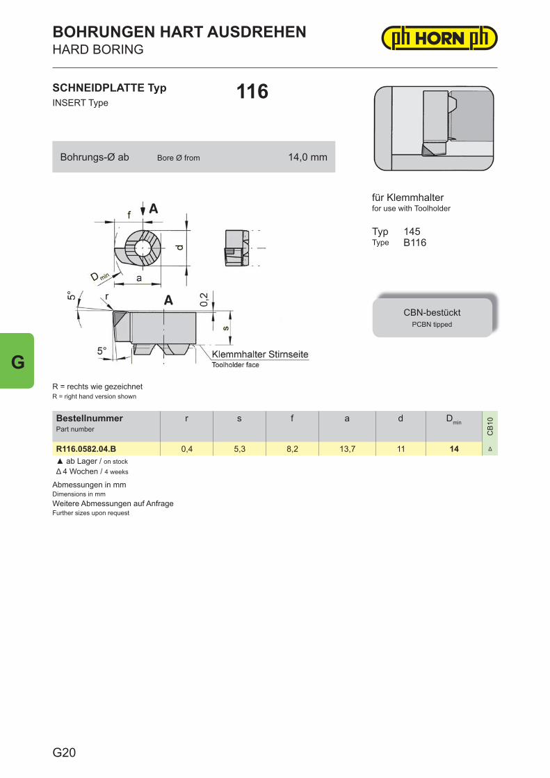
Abmessungen in mmDimensions in mmWeitere Abmessungen auf AnfrageFurther sizes upon request
BestellnummerPart number
r s f a d Dmin
CB
10
R116.0582.04.B 0,4 5,3 8,2 13,7 11 14 Δ
▲ ab Lager / on stockΔ 4 Wochen / 4 weeks
SCHNEIDPLATTE TypINSERT Type
116
BOHRUNGEN HART AUSDREHENHARD BORING
for use with Toolholder
TypType
CBN-bestücktPCBN tipped
145B116
R = rechts wie gezeichnetR = right hand version shown
für Klemmhalter
Bohrungs-Ø ab Bore Ø from 14,0 mm
G20
G
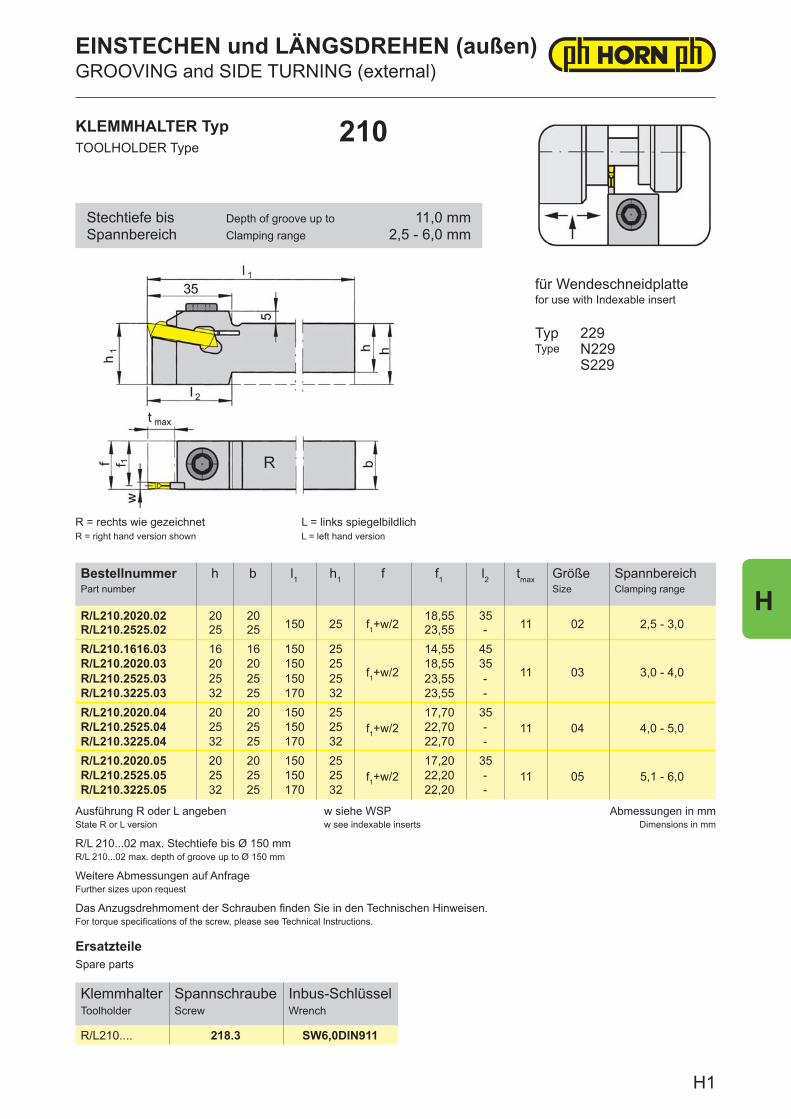
ErsatzteileSpare parts
KlemmhalterToolholder
SpannschraubeScrew
Inbus-SchlüsselWrench
R/L210.... 218.3 SW6,0DIN911
Ausführung R oder L angebenState R or L version
w siehe WSPw see indexable inserts
Abmessungen in mmDimensions in mm
Das Anzugsdrehmoment der Schrauben finden Sie in den Technischen Hinweisen.For torque specifications of the screw, please see Technical Instructions.
R/L 210...02 max. Stechtiefe bis Ø 150 mmR/L 210...02 max. depth of groove up to Ø 150 mm
Weitere Abmessungen auf AnfrageFurther sizes upon request
BestellnummerPart number
h b l1 h1 f f1 l2 tmax GrößeSize
SpannbereichClamping range
R/L210.2020.02 20 20150 25 f1+w/2
18,55 3511 02 2,5 - 3,0R/L210.2525.02 25 25 23,55 -
R/L210.1616.03 16 16 150 25
f1+w/2
14,55 45
11 03 3,0 - 4,0R/L210.2020.03 20 20 150 25 18,55 35R/L210.2525.03 25 25 150 25 23,55 -R/L210.3225.03 32 25 170 32 23,55 -R/L210.2020.04 20 20 150 25
f1+w/217,70 35
11 04 4,0 - 5,0R/L210.2525.04 25 25 150 25 22,70 -R/L210.3225.04 32 25 170 32 22,70 -R/L210.2020.05 20 20 150 25
f1+w/217,20 35
11 05 5,1 - 6,0R/L210.2525.05 25 25 150 25 22,20 -R/L210.3225.05 32 25 170 32 22,20 -
KLEMMHALTER TypTOOLHOLDER Type
210
für Wendeschneidplattefor use with Indexable insert
TypType
229N229S229
R = rechts wie gezeichnetR = right hand version shown
L = links spiegelbildlichL = left hand version
Stechtiefe bisSpannbereich
Depth of groove up toClamping range
11,0 mm2,5 - 6,0 mm
EINSTECHEN und LÄNGSDREHEN (außen)GROOVING and SIDE TURNING (external)
H1
H
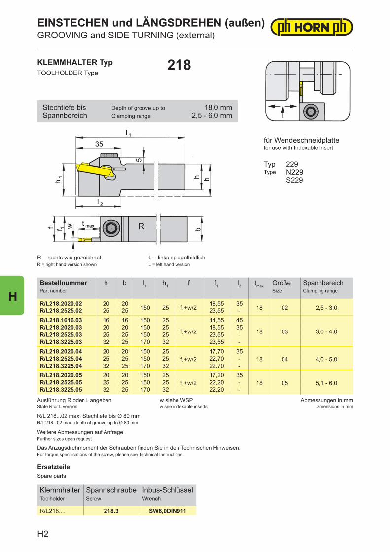
ErsatzteileSpare parts
KlemmhalterToolholder
SpannschraubeScrew
Inbus-SchlüsselWrench
R/L218.... 218.3 SW6,0DIN911
Ausführung R oder L angebenState R or L version
w siehe WSPw see indexable inserts
Abmessungen in mmDimensions in mm
Das Anzugsdrehmoment der Schrauben finden Sie in den Technischen Hinweisen.For torque specifications of the screw, please see Technical Instructions.
R/L 218...02 max. Stechtiefe bis Ø 80 mmR/L 218...02 max. depth of groove up to Ø 80 mm
Weitere Abmessungen auf AnfrageFurther sizes upon request
BestellnummerPart number
h b l1 h1 f f1 l2 tmax GrößeSize
SpannbereichClamping range
R/L218.2020.02 20 20150 25 f1+w/2
18,55 3518 02 2,5 - 3,0R/L218.2525.02 25 25 23,55 -
R/L218.1616.03 16 16 150 25
f1+w/2
14,55 45
18 03 3,0 - 4,0R/L218.2020.03 20 20 150 25 18,55 35R/L218.2525.03 25 25 150 25 23,55 -R/L218.3225.03 32 25 170 32 23,55 -R/L218.2020.04 20 20 150 25
f1+w/217,70 35
18 04 4,0 - 5,0R/L218.2525.04 25 25 150 25 22,70 -R/L218.3225.04 32 25 170 32 22,70 -R/L218.2020.05 20 20 150 25
f1+w/217,20 35
18 05 5,1 - 6,0R/L218.2525.05 25 25 150 25 22,20 -R/L218.3225.05 32 25 170 32 22,20 -
KLEMMHALTER TypTOOLHOLDER Type
218
R = rechts wie gezeichnetR = right hand version shown
L = links spiegelbildlichL = left hand version
für Wendeschneidplattefor use with Indexable insert
TypType
229N229S229
Stechtiefe bisSpannbereich
Depth of groove up toClamping range
18,0 mm2,5 - 6,0 mm
EINSTECHEN und LÄNGSDREHEN (außen)GROOVING and SIDE TURNING (external)
H2
H
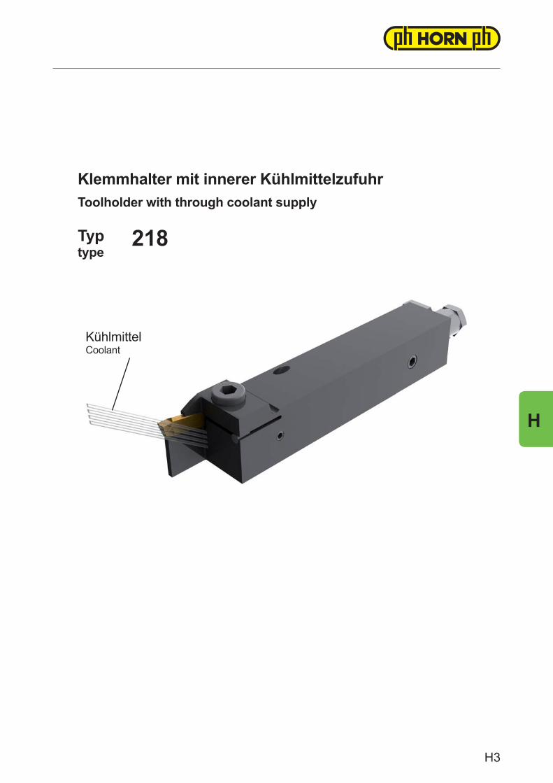
KühlmittelCoolant
Typtype
Klemmhalter mit innerer KühlmittelzufuhrToolholder with through coolant supply
218
H3
H
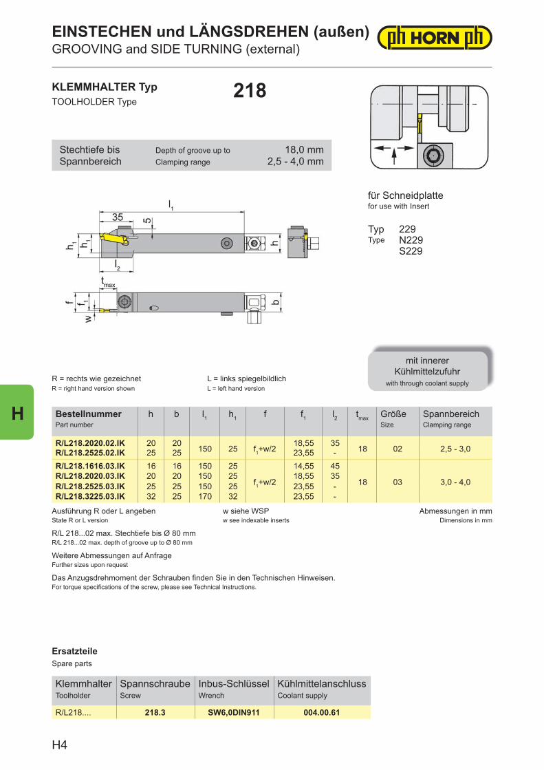
ErsatzteileSpare parts
KlemmhalterToolholder
SpannschraubeScrew
Inbus-SchlüsselWrench
KühlmittelanschlussCoolant supply
R/L218.... 218.3 SW6,0DIN911 004.00.61
Ausführung R oder L angebenState R or L version
w siehe WSPw see indexable inserts
Abmessungen in mmDimensions in mm
Das Anzugsdrehmoment der Schrauben fi nden Sie in den Technischen Hinweisen.For torque specifi cations of the screw, please see Technical Instructions.
R/L 218...02 max. Stechtiefe bis Ø 80 mmR/L 218...02 max. depth of groove up to Ø 80 mm
Weitere Abmessungen auf AnfrageFurther sizes upon request
BestellnummerPart number
h b l1 h1 f f1 l2 tmax GrößeSize
SpannbereichClamping range
R/L218.2020.02.IK 20 20150 25 f1+w/2
18,55 3518 02 2,5 - 3,0R/L218.2525.02.IK 25 25 23,55 -
R/L218.1616.03.IK 16 16 150 25
f1+w/2
14,55 45
18 03 3,0 - 4,0R/L218.2020.03.IK 20 20 150 25 18,55 35R/L218.2525.03.IK 25 25 150 25 23,55 -R/L218.3225.03.IK 32 25 170 32 23,55 -
KLEMMHALTER TypTOOLHOLDER Type
218
R = rechts wie gezeichnetR = right hand version shown
L = links spiegelbildlichL = left hand version
für Schneidplattefor use with Insert
TypType
mit innerer Kühlmittelzufuhr
with through coolant supply
229N229S229
Stechtiefe bisSpannbereich
Depth of groove up toClamping range
18,0 mm2,5 - 4,0 mm
EINSTECHEN und LÄNGSDREHEN (außen)GROOVING and SIDE TURNING (external)
H4
H
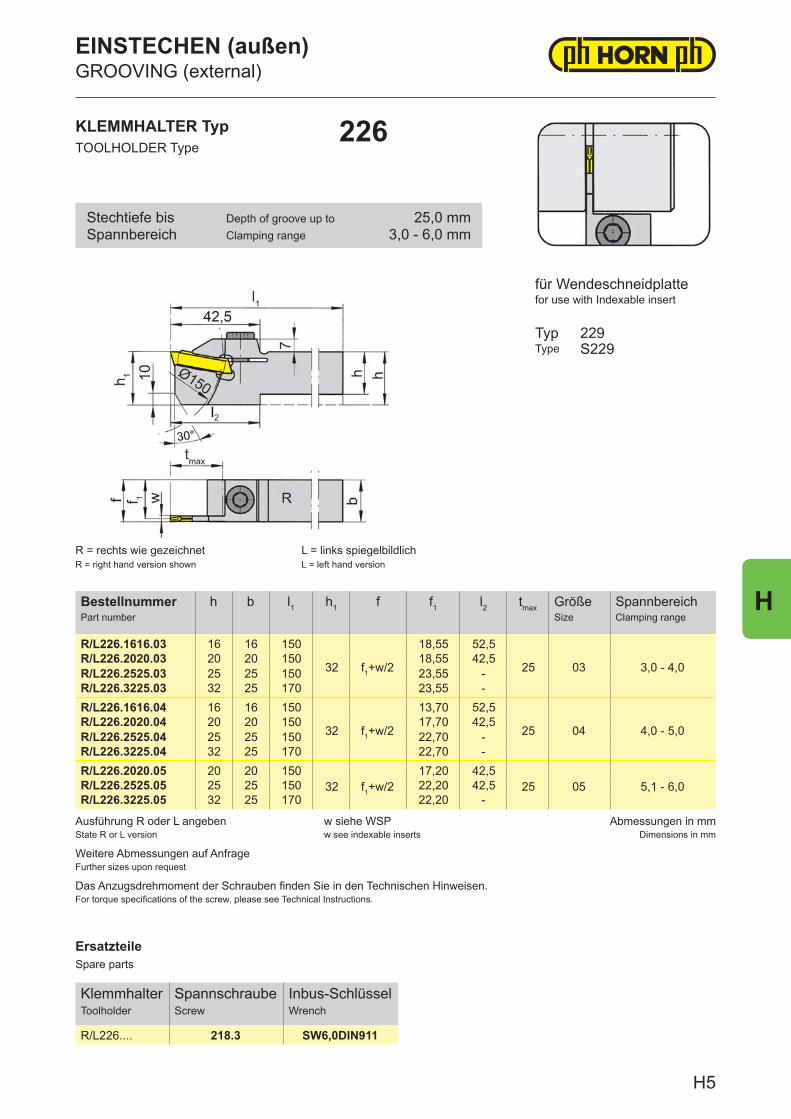
ErsatzteileSpare parts
KlemmhalterToolholder
SpannschraubeScrew
Inbus-SchlüsselWrench
R/L226.... 218.3 SW6,0DIN911
Ausführung R oder L angebenState R or L version
w siehe WSPw see indexable inserts
Abmessungen in mmDimensions in mm
Weitere Abmessungen auf AnfrageFurther sizes upon request
Das Anzugsdrehmoment der Schrauben finden Sie in den Technischen Hinweisen.For torque specifications of the screw, please see Technical Instructions.
BestellnummerPart number
h b l1 h1 f f1 l2 tmax GrößeSize
SpannbereichClamping range
R/L226.1616.03 16 16 150
32 f1+w/2
18,55 52,5
25 03 3,0 - 4,0R/L226.2020.03 20 20 150 18,55 42,5R/L226.2525.03 25 25 150 23,55 -R/L226.3225.03 32 25 170 23,55 -R/L226.1616.04 16 16 150
32 f1+w/2
13,70 52,5
25 04 4,0 - 5,0R/L226.2020.04 20 20 150 17,70 42,5R/L226.2525.04 25 25 150 22,70 -R/L226.3225.04 32 25 170 22,70 -R/L226.2020.05 20 20 150
32 f1+w/217,20 42,5
25 05 5,1 - 6,0R/L226.2525.05 25 25 150 22,20 42,5R/L226.3225.05 32 25 170 22,20 -
KLEMMHALTER TypTOOLHOLDER Type
226
für Wendeschneidplattefor use with Indexable insert
TypType
229S229
R = rechts wie gezeichnetR = right hand version shown
L = links spiegelbildlichL = left hand version
Stechtiefe bisSpannbereich
Depth of groove up toClamping range
25,0 mm3,0 - 6,0 mm
EINSTECHEN (außen)GROOVING (external)
H5
H
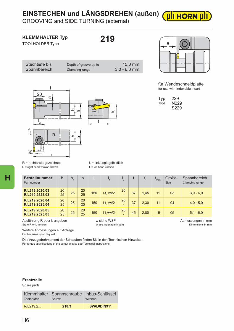
ErsatzteileSpare parts
KlemmhalterToolholder
SpannschraubeScrew
Inbus-SchlüsselWrench
R/L219.2... 218.3 SW6,0DIN911
Ausführung R oder L angebenState R or L version
w siehe WSPw see indexable inserts
Abmessungen in mmDimensions in mm
Weitere Abmessungen auf AnfrageFurther sizes upon request
Das Anzugsdrehmoment der Schrauben finden Sie in den Technischen Hinweisen.For torque specifications of the screw, please see Technical Instructions.
BestellnummerPart number
h h1 b l l1 l2 f f1 tmax GrößeSize
SpannbereichClamping range
R/L219.2020.03 2025
20150 l-f1+w/2
2037 1,45 11 03 3,0 - 4,0R/L219.2525.03 25 25 -
R/L219.2020.04 2025
20150 l-f1+w/2
2037 2,30 11 04 4,0 - 5,0R/L219.2525.04 25 25 -
R/L219.2020.05 2025
20150 l-f1+w/2
2345 2,80 15 05 5,1 - 6,0R/L219.2525.05 25 25 -
KLEMMHALTER TypTOOLHOLDER Type
219
R = rechts wie gezeichnetR = right hand version shown
L = links spiegelbildlichL = left hand version
für Wendeschneidplattefor use with Indexable insert
TypType
229N229S229
Stechtiefe bisSpannbereich
Depth of groove up toClamping range
15,0 mm3,0 - 6,0 mm
EINSTECHEN und LÄNGSDREHEN (außen)GROOVING and SIDE TURNING (external)
H6
H
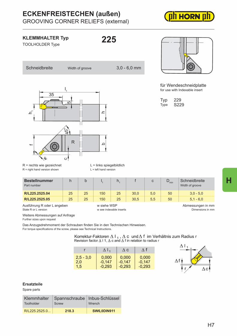
ErsatzteileSpare parts
KlemmhalterToolholder
SpannschraubeScrew
Inbus-SchlüsselWrench
R/L225.2525.0... 218.3 SW6,0DIN911
Ausführung R oder L angebenState R or L version
w siehe WSPw see indexable inserts
Abmessungen in mmDimensions in mm
Weitere Abmessungen auf AnfrageFurther sizes upon request
Das Anzugsdrehmoment der Schrauben finden Sie in den Technischen Hinweisen.For torque specifications of the screw, please see Technical Instructions.
BestellnummerPart number
h b l1 h1 f c Dmin SchneidbreiteWidth of groove
R/L225.2525.04 25 25 150 25 30,0 5,0 50 3,0 - 5,0R/L225.2525.05 25 25 150 25 30,5 5,5 50 5,1 - 6,0
KLEMMHALTER TypTOOLHOLDER Type
225
für Wendeschneidplattefor use with Indexable insert
TypType
229S229
R = rechts wie gezeichnetR = right hand version shown
L = links spiegelbildlichL = left hand version
Schneidbreite Width of groove 3,0 - 6,0 mm
ECKENFREISTECHEN (außen)GROOVING CORNER RELIEFS (external)
H7
H
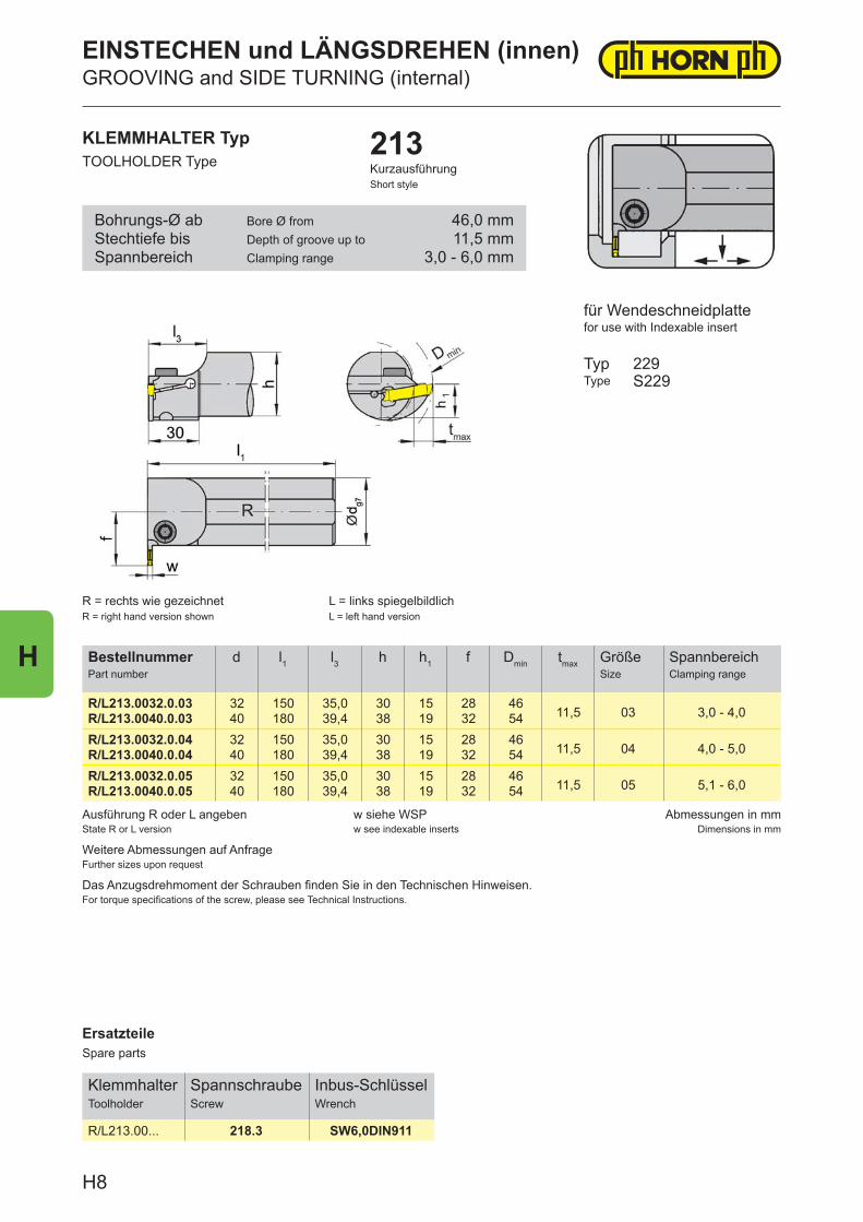
ErsatzteileSpare parts
KlemmhalterToolholder
SpannschraubeScrew
Inbus-SchlüsselWrench
R/L213.00... 218.3 SW6,0DIN911
Ausführung R oder L angebenState R or L version
w siehe WSPw see indexable inserts
Abmessungen in mmDimensions in mm
Weitere Abmessungen auf AnfrageFurther sizes upon request
Das Anzugsdrehmoment der Schrauben finden Sie in den Technischen Hinweisen.For torque specifications of the screw, please see Technical Instructions.
BestellnummerPart number
d l1 l3 h h1 f Dmin tmax GrößeSize
SpannbereichClamping range
R/L213.0032.0.03 32 150 35,0 30 15 28 4611,5 03 3,0 - 4,0R/L213.0040.0.03 40 180 39,4 38 19 32 54
R/L213.0032.0.04 32 150 35,0 30 15 28 4611,5 04 4,0 - 5,0R/L213.0040.0.04 40 180 39,4 38 19 32 54
R/L213.0032.0.05 32 150 35,0 30 15 28 4611,5 05 5,1 - 6,0R/L213.0040.0.05 40 180 39,4 38 19 32 54
KLEMMHALTER TypTOOLHOLDER Type
213KurzausführungShort style
R = rechts wie gezeichnetR = right hand version shown
L = links spiegelbildlichL = left hand version
für Wendeschneidplattefor use with Indexable insert
TypType
229S229
Bohrungs-Ø abStechtiefe bisSpannbereich
Bore Ø fromDepth of groove up toClamping range
46,0 mm11,5 mm
3,0 - 6,0 mm
EINSTECHEN und LÄNGSDREHEN (innen)GROOVING and SIDE TURNING (internal)
H8
H
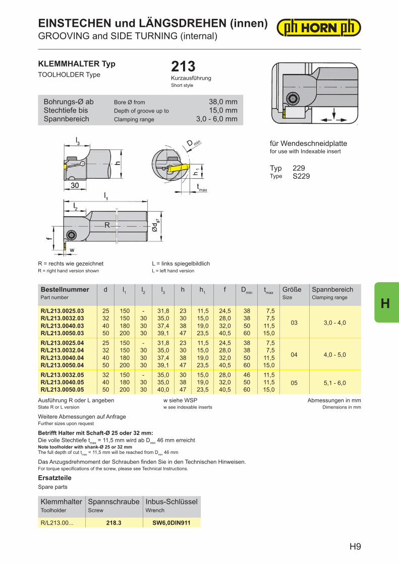
ErsatzteileSpare parts
KlemmhalterToolholder
SpannschraubeScrew
Inbus-SchlüsselWrench
R/L213.00... 218.3 SW6,0DIN911
Ausführung R oder L angebenState R or L version
w siehe WSPw see indexable inserts
Abmessungen in mmDimensions in mm
Das Anzugsdrehmoment der Schrauben finden Sie in den Technischen Hinweisen.For torque specifications of the screw, please see Technical Instructions.
Weitere Abmessungen auf AnfrageFurther sizes upon request
Betrifft Halter mit Schaft-Ø 25 oder 32 mm:Die volle Stechtiefe tmax = 11,5 mm wird ab Dmin 46 mm erreichtNote toolholder with shank-Ø 25 or 32 mmThe full depth of cut tmax = 11,5 mm will be reached from Dmin 46 mm
BestellnummerPart number
d l1 l2 l3 h h1 f Dmin tmax GrößeSize
SpannbereichClamping range
R/L213.0025.03 25 150 - 31,8 23 11,5 24,5 38 7,5
03 3,0 - 4,0R/L213.0032.03 32 150 30 35,0 30 15,0 28,0 38 7,5R/L213.0040.03 40 180 30 37,4 38 19,0 32,0 50 11,5R/L213.0050.03 50 200 30 39,1 47 23,5 40,5 60 15,0R/L213.0025.04 25 150 - 31,8 23 11,5 24,5 38 7,5
04 4,0 - 5,0R/L213.0032.04 32 150 30 35,0 30 15,0 28,0 38 7,5R/L213.0040.04 40 180 30 37,4 38 19,0 32,0 50 11,5R/L213.0050.04 50 200 30 39,1 47 23,5 40,5 60 15,0R/L213.0032.05 32 150 - 35,0 30 15,0 28,0 46 11,5
05 5,1 - 6,0R/L213.0040.05 40 180 30 35,0 38 19,0 32,0 50 11,5R/L213.0050.05 50 200 30 40,0 47 23,5 40,5 60 15,0
KLEMMHALTER TypTOOLHOLDER Type
213KurzausführungShort style
für Wendeschneidplattefor use with Indexable insert
TypType
229S229
R = rechts wie gezeichnetR = right hand version shown
L = links spiegelbildlichL = left hand version
Bohrungs-Ø abStechtiefe bisSpannbereich
Bore Ø fromDepth of groove up toClamping range
38,0 mm15,0 mm
3,0 - 6,0 mm
EINSTECHEN und LÄNGSDREHEN (innen)GROOVING and SIDE TURNING (internal)
H9
H
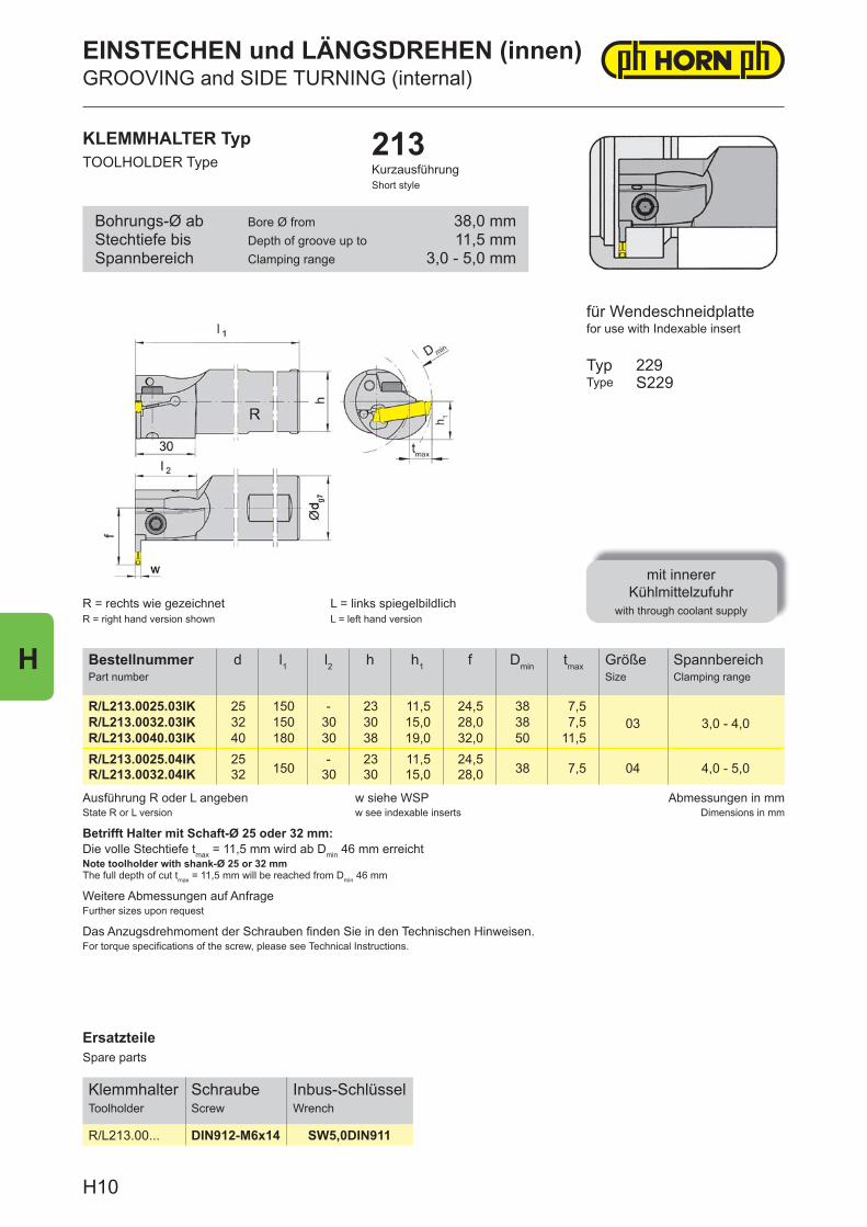
ErsatzteileSpare parts
KlemmhalterToolholder
SchraubeScrew
Inbus-SchlüsselWrench
R/L213.00... DIN912-M6x14 SW5,0DIN911
Ausführung R oder L angebenState R or L version
w siehe WSPw see indexable inserts
Abmessungen in mmDimensions in mm
Das Anzugsdrehmoment der Schrauben fi nden Sie in den Technischen Hinweisen.For torque specifi cations of the screw, please see Technical Instructions.
Betrifft Halter mit Schaft-Ø 25 oder 32 mm:Die volle Stechtiefe tmax = 11,5 mm wird ab Dmin 46 mm erreichtNote toolholder with shank-Ø 25 or 32 mmThe full depth of cut tmax = 11,5 mm will be reached from Dmin 46 mm
Weitere Abmessungen auf AnfrageFurther sizes upon request
BestellnummerPart number
d l1 l2 h h1 f Dmin tmax GrößeSize
SpannbereichClamping range
R/L213.0025.03IK 25 150 - 23 11,5 24,5 38 7,503 3,0 - 4,0R/L213.0032.03IK 32 150 30 30 15,0 28,0 38 7,5
R/L213.0040.03IK 40 180 30 38 19,0 32,0 50 11,5R/L213.0025.04IK 25
150- 23 11,5 24,5
38 7,5 04 4,0 - 5,0R/L213.0032.04IK 32 30 30 15,0 28,0
KLEMMHALTER TypTOOLHOLDER Type
213KurzausführungShort style
R = rechts wie gezeichnetR = right hand version shown
L = links spiegelbildlichL = left hand version
für Wendeschneidplattefor use with Indexable insert
TypType
mit innerer Kühlmittelzufuhr
with through coolant supply
229S229
Bohrungs-Ø abStechtiefe bisSpannbereich
Bore Ø fromDepth of groove up toClamping range
38,0 mm11,5 mm
3,0 - 5,0 mm
EINSTECHEN und LÄNGSDREHEN (innen)GROOVING and SIDE TURNING (internal)
H10
H
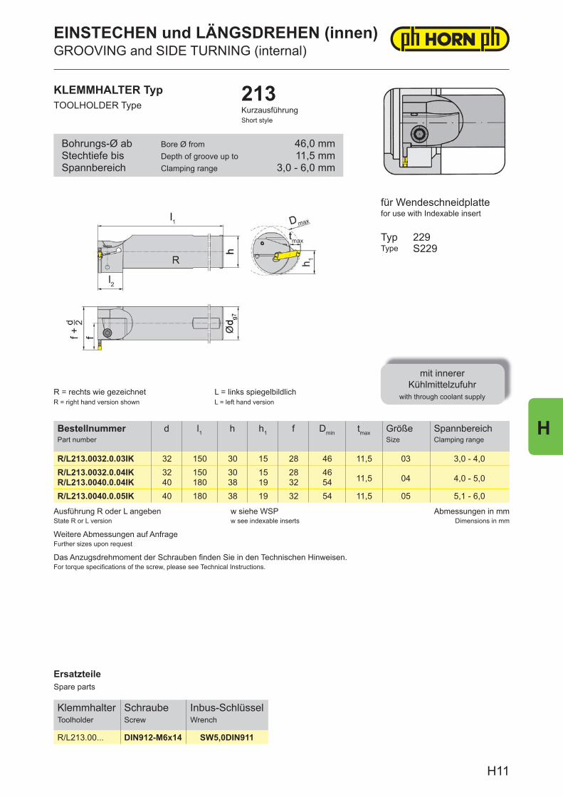
ErsatzteileSpare parts
KlemmhalterToolholder
SchraubeScrew
Inbus-SchlüsselWrench
R/L213.00... DIN912-M6x14 SW5,0DIN911
Ausführung R oder L angebenState R or L version
w siehe WSPw see indexable inserts
Abmessungen in mmDimensions in mm
Weitere Abmessungen auf AnfrageFurther sizes upon request
Das Anzugsdrehmoment der Schrauben fi nden Sie in den Technischen Hinweisen.For torque specifi cations of the screw, please see Technical Instructions.
BestellnummerPart number
d l1 h h1 f Dmin tmax GrößeSize
SpannbereichClamping range
R/L213.0032.0.03IK 32 150 30 15 28 46 11,5 03 3,0 - 4,0R/L213.0032.0.04IK 32 150 30 15 28 46
11,5 04 4,0 - 5,0R/L213.0040.0.04IK 40 180 38 19 32 54R/L213.0040.0.05IK 40 180 38 19 32 54 11,5 05 5,1 - 6,0
KLEMMHALTER TypTOOLHOLDER Type
213KurzausführungShort style
für Wendeschneidplattefor use with Indexable insert
TypType
mit innerer Kühlmittelzufuhr
with through coolant supply
229S229
R = rechts wie gezeichnetR = right hand version shown
L = links spiegelbildlichL = left hand version
Bohrungs-Ø abStechtiefe bisSpannbereich
Bore Ø fromDepth of groove up toClamping range
46,0 mm11,5 mm
3,0 - 6,0 mm
EINSTECHEN und LÄNGSDREHEN (innen)GROOVING and SIDE TURNING (internal)
H11
H
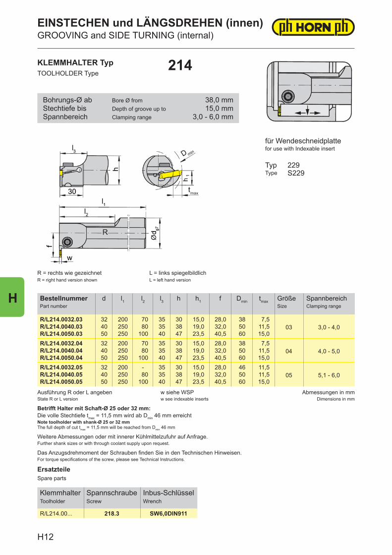
ErsatzteileSpare parts
KlemmhalterToolholder
SpannschraubeScrew
Inbus-SchlüsselWrench
R/L214.00... 218.3 SW6,0DIN911
Ausführung R oder L angebenState R or L version
w siehe WSPw see indexable inserts
Abmessungen in mmDimensions in mm
Das Anzugsdrehmoment der Schrauben finden Sie in den Technischen Hinweisen.For torque specifications of the screw, please see Technical Instructions.
Betrifft Halter mit Schaft-Ø 25 oder 32 mm:Die volle Stechtiefe tmax = 11,5 mm wird ab Dmin 46 mm erreichtNote toolholder with shank-Ø 25 or 32 mmThe full depth of cut tmax = 11,5 mm will be reached from Dmin 46 mm
Weitere Abmessungen oder mit innerer Kühlmittelzufuhr auf Anfrage.Further shank sizes or with through coolant supply upon request.
BestellnummerPart number
d l1 l2 l3 h h1 f Dmin tmax GrößeSize
SpannbereichClamping range
R/L214.0032.03 32 200 70 35 30 15,0 28,0 38 7,503 3,0 - 4,0R/L214.0040.03 40 250 80 35 38 19,0 32,0 50 11,5
R/L214.0050.03 50 250 100 40 47 23,5 40,5 60 15,0R/L214.0032.04 32 200 70 35 30 15,0 28,0 38 7,5
04 4,0 - 5,0R/L214.0040.04 40 250 80 35 38 19,0 32,0 50 11,5R/L214.0050.04 50 250 100 40 47 23,5 40,5 60 15,0R/L214.0032.05 32 200 - 35 30 15,0 28,0 46 11,5
05 5,1 - 6,0R/L214.0040.05 40 250 80 35 38 19,0 32,0 50 11,5R/L214.0050.05 50 250 100 40 47 23,5 40,5 60 15,0
KLEMMHALTER TypTOOLHOLDER Type
214
R = rechts wie gezeichnetR = right hand version shown
L = links spiegelbildlichL = left hand version
für Wendeschneidplattefor use with Indexable insert
TypType
229S229
Bohrungs-Ø abStechtiefe bisSpannbereich
Bore Ø fromDepth of groove up toClamping range
38,0 mm15,0 mm
3,0 - 6,0 mm
EINSTECHEN und LÄNGSDREHEN (innen)GROOVING and SIDE TURNING (internal)
H12
H
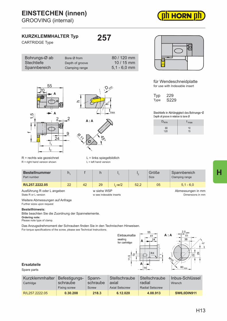
ErsatzteileSpare parts
KurzklemmhalterCartridge
Befestigungs-schraubeFixing screw
Spann-schraubeScrew
Stellschraube axialAxial Setscrew
Stellschraube radialRadial Setscrew
Inbus-SchlüsselWrench
R/L257.2222.05 0.30.208 218.3 6.12.020 4.08.913 SW6,0DIN911
Ausführung R oder L angebenState R or L version
w siehe WSPw see indexable inserts
Abmessungen in mmDimensions in mm
Das Anzugsdrehmoment der Schrauben finden Sie in den Technischen Hinweisen.For torque specifications of the screw, please see Technical Instructions.
Weitere Abmessungen auf AnfrageFurther sizes upon request
Bestellhinweis:Bitte beachten Sie die Zuordnung der Spannelemente.Ordering note:Please note type of clamp.
BestellnummerPart number
h1 f h l1 l2 GrößeSize
SpannbereichClamping range
R/L257.2222.05 22 42 29 l2-w/2 52,2 05 5,1 - 6,0
KURZKLEMMHALTER TypCARTRIDGE Type
257
für Wendeschneidplattefor use with Indexable insert
TypType
229S229
R = rechts wie gezeichnetR = right hand version shown
L = links spiegelbildlichL = left hand version
Bohrungs-Ø abStechtiefeSpannbereich
Bore Ø fromDepth of grooveClamping range
80 / 120 mm10 / 15 mm
5,1 - 6,0 mm
EINSTECHEN (innen)GROOVING (internal)
H13
H
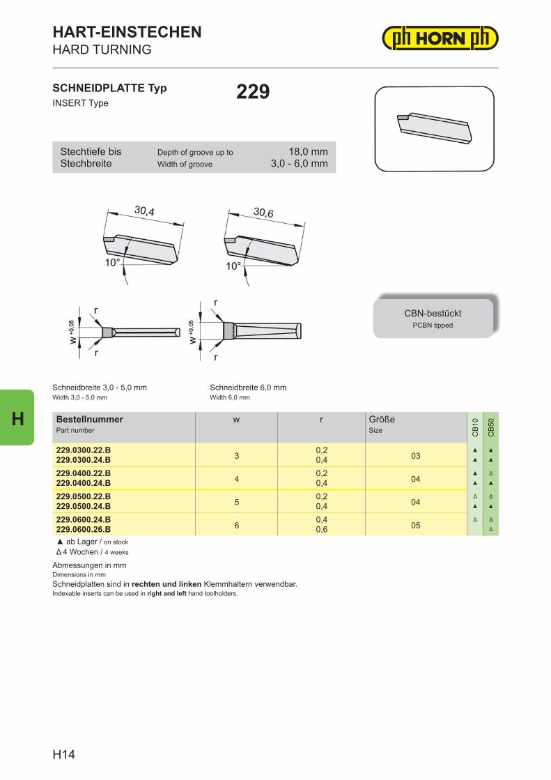
Abmessungen in mmDimensions in mmSchneidplatten sind in rechten und linken Klemmhaltern verwendbar.Indexable inserts can be used in right and left hand toolholders.
BestellnummerPart number
w r GrößeSize C
B10
CB
50
229.0300.22.B3
0,203
▲ ▲
229.0300.24.B 0,4 ▲ ▲
229.0400.22.B4
0,204
▲ Δ
229.0400.24.B 0,4 ▲ ▲
229.0500.22.B5
0,204
Δ Δ
229.0500.24.B 0,4 ▲ ▲
229.0600.24.B6
0,405
Δ Δ
229.0600.26.B 0,6 Δ
▲ ab Lager / on stockΔ 4 Wochen / 4 weeks
SCHNEIDPLATTE TypINSERT Type
229
HART-EINSTECHENHARD TURNING
CBN-bestücktPCBN tipped
Schneidbreite 3,0 - 5,0 mmWidth 3,0 - 5,0 mm
Schneidbreite 6,0 mmWidth 6,0 mm
Stechtiefe bisStechbreite
Depth of groove up toWidth of groove
18,0 mm3,0 - 6,0 mm
H14
H
Technische Hinweise, ZubehörTechnical Instructions, Additional equipment
J1
J
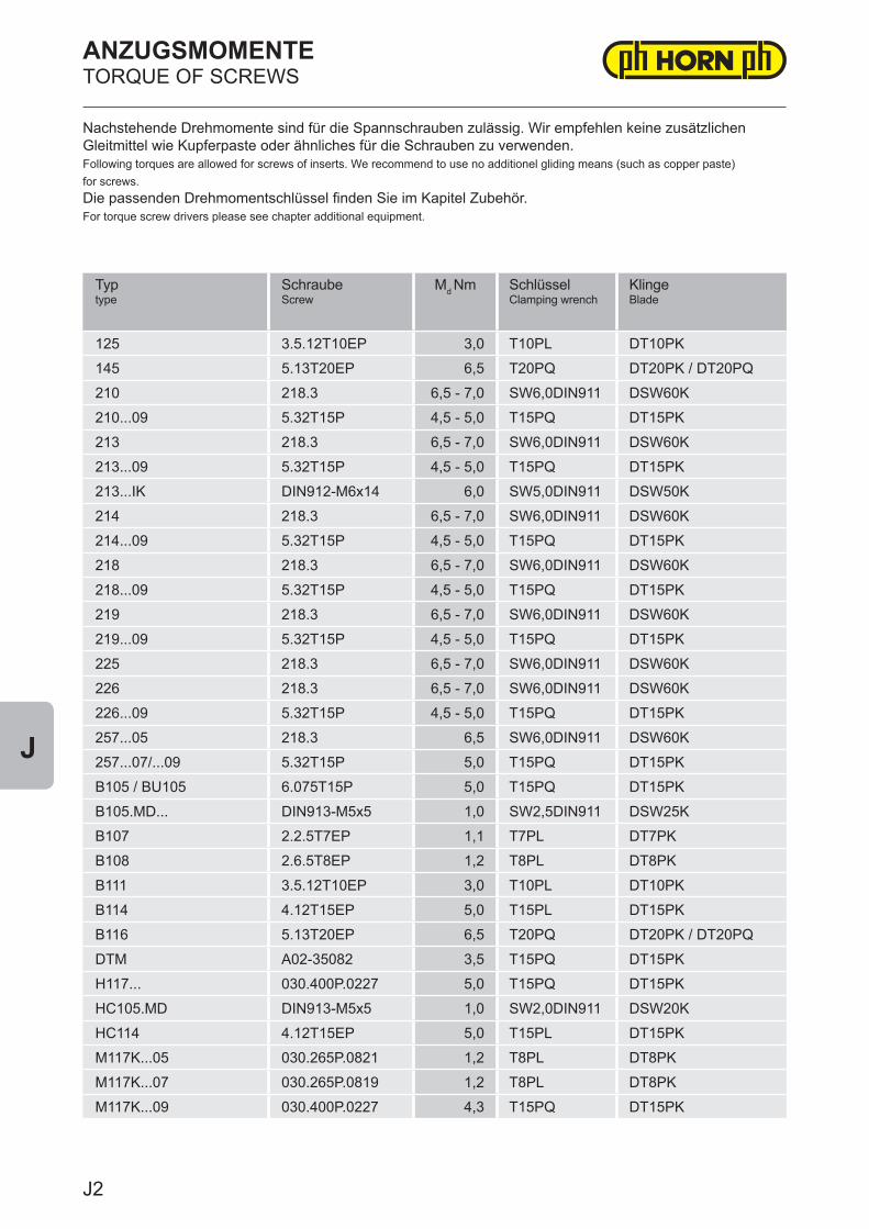
Typtype
SchraubeScrew
Md Nm SchlüsselClamping wrench
KlingeBlade
125 3.5.12T10EP 3,0 T10PL DT10PK
145 5.13T20EP 6,5 T20PQ DT20PK / DT20PQ
210 218.3 6,5 - 7,0 SW6,0DIN911 DSW60K
210...09 5.32T15P 4,5 - 5,0 T15PQ DT15PK
213 218.3 6,5 - 7,0 SW6,0DIN911 DSW60K
213...09 5.32T15P 4,5 - 5,0 T15PQ DT15PK
213...IK DIN912-M6x14 6,0 SW5,0DIN911 DSW50K
214 218.3 6,5 - 7,0 SW6,0DIN911 DSW60K
214...09 5.32T15P 4,5 - 5,0 T15PQ DT15PK
218 218.3 6,5 - 7,0 SW6,0DIN911 DSW60K
218...09 5.32T15P 4,5 - 5,0 T15PQ DT15PK
219 218.3 6,5 - 7,0 SW6,0DIN911 DSW60K
219...09 5.32T15P 4,5 - 5,0 T15PQ DT15PK
225 218.3 6,5 - 7,0 SW6,0DIN911 DSW60K
226 218.3 6,5 - 7,0 SW6,0DIN911 DSW60K
226...09 5.32T15P 4,5 - 5,0 T15PQ DT15PK
257...05 218.3 6,5 SW6,0DIN911 DSW60K
257...07/...09 5.32T15P 5,0 T15PQ DT15PK
B105 / BU105 6.075T15P 5,0 T15PQ DT15PK
B105.MD... DIN913-M5x5 1,0 SW2,5DIN911 DSW25K
B107 2.2.5T7EP 1,1 T7PL DT7PK
B108 2.6.5T8EP 1,2 T8PL DT8PK
B111 3.5.12T10EP 3,0 T10PL DT10PK
B114 4.12T15EP 5,0 T15PL DT15PK
B116 5.13T20EP 6,5 T20PQ DT20PK / DT20PQ
DTM A02-35082 3,5 T15PQ DT15PK
H117... 030.400P.0227 5,0 T15PQ DT15PK
HC105.MD DIN913-M5x5 1,0 SW2,0DIN911 DSW20K
HC114 4.12T15EP 5,0 T15PL DT15PK
M117K...05 030.265P.0821 1,2 T8PL DT8PK
M117K...07 030.265P.0819 1,2 T8PL DT8PK
M117K...09 030.400P.0227 4,3 T15PQ DT15PK
ANZUGSMOMENTETORQUE OF SCREWS
Nachstehende Drehmomente sind für die Spannschrauben zulässig. Wir empfehlen keine zusätzlichen Gleitmittel wie Kupferpaste oder ähnliches für die Schrauben zu verwenden.Following torques are allowed for screws of inserts. We recommend to use no additionel gliding means (such as copper paste) for screws.Die passenden Drehmomentschlüssel finden Sie im Kapitel Zubehör.For torque screw drivers please see chapter additional equipment.
J2
J
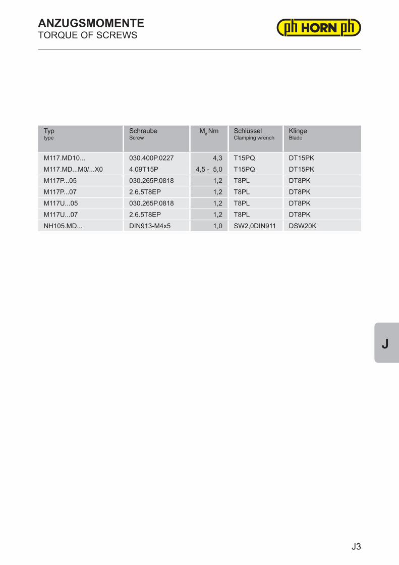
Typtype
SchraubeScrew
Md Nm SchlüsselClamping wrench
KlingeBlade
M117.MD10... 030.400P.0227 4,3 T15PQ DT15PK
M117.MD...M0/...X0 4.09T15P 4,5 - 5,0 T15PQ DT15PK
M117P...05 030.265P.0818 1,2 T8PL DT8PK
M117P...07 2.6.5T8EP 1,2 T8PL DT8PK
M117U...05 030.265P.0818 1,2 T8PL DT8PK
M117U...07 2.6.5T8EP 1,2 T8PL DT8PK
NH105.MD... DIN913-M4x5 1,0 SW2,0DIN911 DSW20K
ANZUGSMOMENTETORQUE OF SCREWS
J3
J
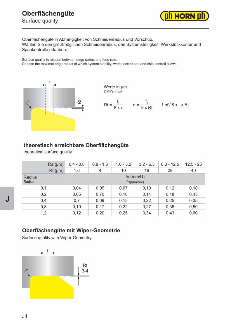
theoretisch erreichbare Oberflächengütetheoretical surface quality
Ra (μm) 0,4 - 0,8 0,8 - 1,6 1,6 - 3,2 3,2 - 6,3 6,3 - 12,5 12,5 - 25Rt (μm) 1,6 4 10 16 28 40
RadiusRadius
fn (mm/U) fn(mm/rev)
0,1 0,04 0,05 0,07 0,10 0,12 0,180,2 0,05 0,70 0,10 0,14 0,18 0,450,4 0,7 0,09 0,15 0,22 0,25 0,350,8 0,10 0,17 0,22 0,27 0,35 0,501,2 0,12 0,20 0,25 0,34 0,43 0,60
f
r Rt
f
rRt3-4
OberflächengüteSurface quality
Oberflächengüte in Abhängigkeit von Schneidenradius und Vorschub.Wählen Sie den größtmöglichen Schneidenradius, den Systemsteifigkeit, Werkstückkontur und Spankontrolle erlauben.
Surface quality in relation between edge radius and feed rate.Choose the maximal edge radius of which system stability, workpiece shape and chip controll allows.
Werte in μmData's in μm
Rt = f =r =f2
8 x rf2
8 x Rt 8 x r x Rt
Oberflächengüte mit Wiper-GeometrieSurface quality with Wiper-Geometry
J4
J
For the purpose of high performance cutting in the fields turning and milling, we developed a large number of inserts with WIPER geometry. Those geometries are designed with a trailing edge between edge radius and lateral cutting edge, which works like a cutting edge with 0° approach angle. Even with 2 - 4 times higher feed rates you can achieve the same surface qualities. Through reduction of cycle time, the optimal chip control with higher federates and the increase of tool life, you can escalate your productivity while reducing costs at the same time.
Please keep in mind when using Wiper Geometries:The approach angle needs to be applied accurately, in order to achieve the desired wiper effect to get best surface qualities:
CCGW / T = 95 ° DCGW / T = 93° Be aware of the cutting direction. Wiper geometries are designed to trail behind the cutting edge for proper chip flow and surface quality. Facing operations should always be performed form the larger to smaller diameter.
Because of the trailing edge, distortion can occur on radii, chamfers and tapers.
Advantages of Wiper Geometries:
● Better surface qualities at the same cutting parameters● Higher feed rates - Roughing and finishing with one insert is possible● Better chip control through higher feed rates● Higher feed rates reduces the cutting time per workpiece and therefore the wear characteristic and this leads to significantly longer tool life
Wiper GeometrienWiper Geometries
Für die Hochleistungszerspanung haben wir für das Innen- und Außendrehen eine große Anzahl von Plattentypen mit WIPER Geometrie entwickelt. Diese besitzen eine Schleppschneide zwischen Radiusauslauf und seitlicher Schneidkante, die wie eine Nebenschneide mit 0° Anstellwinkel wirkt.Selbst bei einem 2 - 4 fach höherem Vorschub werden dieselben Oberflächengüten erreicht. Durch die Reduzierung der Bearbeitungszeit, der optimalen Spankontrolle und der Standzeiterhöhung steigern Sie die Produktivität in erheblichem Ausmaß bei gleichzeitiger Kostensenkung.
Bitte beachten Sie beim Einsatz der Wiper Geometrien:
Der Anstellwinkel muss genau eingehalten werden, da sonst der gewünschte Schleppschneiden Effekt nicht eintritt und keine guten Oberflächen erreicht werden:
CCGW / T = 95 ° DCGW / T = 93° Beachten Sie die Schneidrichtung, da die Wiper Geometrien durch die Schleppschneide richtungs-gebunden sind. Nur so können die gewünschten Oberflächengüten und ein optimaler Spanfluss erreicht werden.Beim Plandrehen immer vom großen zum kleinen Durchmesser bearbeiten!
Durch die geometrische Auslegung der Schneide kommt es zu Konturverzerrungen bei Radien, Fasen, Schrägen und Freistichen!
Vorteile der Wiper Geometrien:● Bessere Oberflächengüten bei gleichen Bearbeitungsparametern● Höhere Vorschübe - Schruppen und Schlichten mit einer Platte möglich● Besserer Spanbruch durch höhere Vorschübe● Höhere Vorschübe reduzieren die Eingriffszeit pro Teil und dadurch das Verschleißverhalten und erhöhen die Standzeiten erheblich
J5
J
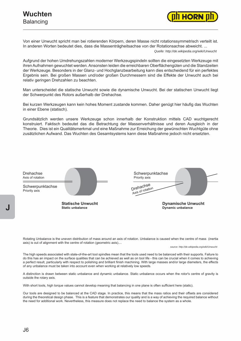
WuchtenBalancing
Von einer Unwucht spricht man bei rotierenden Körpern, deren Masse nicht rotationssymmetrisch verteilt ist. In anderen Worten bedeutet dies, dass die Massenträgheitsachse von der Rotationsachse abweicht. ... Quelle: http://de.wikipedia.org/wiki/Unwucht
Aufgrund der hohen Umdrehungszahlen moderner Werkzeugspindeln sollten die eingesetzten Werkzeuge mit ihren Aufnahmen gewuchtet werden. Ansonsten leiden die erreichbaren Oberflächengüten und die Standzeiten der Werkzeuge. Besonders in der Glanz- und Hochglanzbearbeitung kann dies entscheidend für ein perfektes Ergebnis sein. Bei großen Massen und/oder großen Durchmessern sind die Effekte der Unwucht auch bei relativ geringen Drehzahlen zu beachten.
Man unterscheidet die statische Unwucht sowie die dynamische Unwucht. Bei der statischen Unwucht liegt der Schwerpunkt des Rotors außerhalb der Drehachse.
Bei kurzen Werkzeugen kann kein hohes Moment zustande kommen. Daher genügt hier häufig das Wuchten in einer Ebene (statisch).
Grundsätzlich werden unsere Werkzeuge schon innerhalb der Konstruktion mittels CAD wuchtgerecht konstruiert. Faktisch bedeutet das die Betrachtung der Massenverhältnisse und deren Ausgleich in der Theorie. Dies ist ein Qualitätsmerkmal und eine Maßnahme zur Erreichung der gewünschten Wuchtgüte ohne zusätzlichen Aufwand. Das Wuchten des Gesamtsystems kann diese Maßnahme jedoch nicht ersetzten.
Statische UnwuchtStatic unbalance
Rotating Unbalance is the uneven distribution of mass around an axis of rotation. Unbalance is caused when the centre of mass (inertia axis) is out of alignment with the centre of rotation (geometric axis).... source: http://de.wikipedia.org/wiki/Unwucht
The high speeds associated with state-of-the-art tool spindles mean that the tools used need to be balanced with their supports. Failure to do this has an impact on the surface qualities that can be achieved as well as on tool life - this can be crucial when it comes to achieving a perfect result, particularly with respect to polishing and brilliant finish machining. With large masses and/or large diameters, the effects of any unbalance must be taken into account even when working at relatively low speeds.
A distinction is drawn between static unbalance and dynamic unbalance. Static unbalance occurs when the rotor's centre of gravity is outside the rotary axis.
With short tools, high torque values cannot develop meaning that balancing in one plane is often sufficient here (static).
Our tools are designed to be balanced at the CAD stage. In practice, this means that the mass ratios and their offsets are considered during the theoretical design phase. This is a feature that demonstrates our quality and is a way of achieving the required balance without the need for additional work. Nevertheless, this measure does not replace the need to balance the system as a whole.
Dynamische UnwuchtDynamic unbalance
DrehachseAxis of rotation
SchwerpunktachsePriority axis
SchwerpunktachsePriority axis
Drehachse
Axis of rotation
J6
J
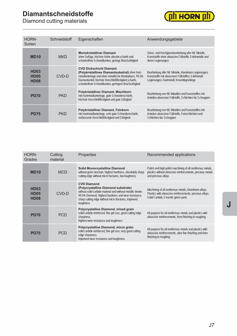
HORN-Sorten
Schneidstoff Eigenschaften Anwendungsgebiete
MD10 MKDMonokristalliner Diamant ohne Gefüge, höchste Härte absolut scharfe und schartenfreie Schneidkanten, geringe Bruchzähigkeit
Glanz- und Hochglanzbearbeitung aller NE Metalle, Kunststoffe ohne abrassive Füllstoffe, Edelmetalle und deren Legierungen
HD03HD05HD08
CVD-D
CVD Dickschicht Diamant(Polykristallines Diamantsubstrat) ohne Hart-metallunterlage und ohne metallische Bindephase, 99,5% Diamantanteil, höchste Verschleißfestigkeit scharfe, schartenfreie Schneidkanten, geringere Bruchzähigkeit
Bearbeitung aller NE Metalle, Aluminium Legierungen, Kunststoffe mit abrassiven Füllstoffen, Edelmetall-Legierungen, Hartmetall, Keramikgrünlinge
PD70 PKDPolykristalliner Diamant, Mischkorn mit Hartmetallunterlage, gute Schneidenschärfe, höchste Verschleißfestigkeit und gute Zähigkeit
Bearbeitung von NE-Metallen und Kunststoffen mit Anteilen abrassiver Füllstoffe, Schlichten bis Schruppen
PD75 PKDPolykristalliner Diamant, Feinkorn mit Hartmetallunterlage, sehr gute Schneidenschärfe, verbesserte Verschleißfestigkeit und Zähigkeit
Bearbeitung von NE-Metallen und Kunststoffen mit Anteilen abrassiver Füllstoffe, Feinschlichten und Schlichten bis Schruppen
HORN-Grades
Cutting material
Properties Recommended applications
MD10 MCDSolid Monocrystalline Diamond without grain structure, highest hardness, absolutely sharp cutting edge without micro fractures, low toughness
Polish and high polish machining of all nonferrous metals, plastics without abrassive reinforcements, precious metals and precious alloys
HD03HD05HD08
CVD-D
CVD Diamond(Polycrystalline Diamond substrate)without solid carbide material and without metallic binder. 99.5% Diamond, Highest hardness and wear resistance, sharp cutting edge without micro fractures, improved toughness
Machining of all nonferrous metals, Aluminium alloys, Plastics with abrassive reinforcements, precious alloys, Solid Carbide, Ceramic green parts
PD70 PCDPolycrystalline Diamond, mixed grainsolid carbide reinforced, fine grit size, good cutting edge sharpness, highest wear resistance and toughness
All purpose for all nonferrous metals and plastics with abrassive reinforcements, from finishing to roughing
PD75 PCDPolycrystalline Diamond, micro grainsolid carbide reinforced, fine grit size, very good cutting edge sharpness, improved wear resistance and toughness
All purpose for all nonferrous metals and plastics with abrassive reinforcements, ultra fine finishing and from finishing to roughing
DiamantschneidstoffeDiamond cutting materials
J7
J
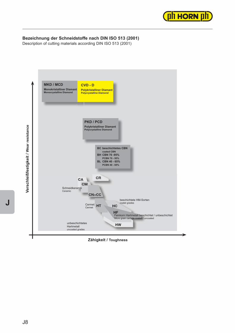
Bezeichnung der Schneidstoffe nach DIN ISO 513 (2001)Description of cutting materials according DIN ISO 513 (2001)
unbeschichtetesHartmetalluncoated grades
Feinkorn Hartmetall beschichtet / unbeschichtetMicro grain carbide coated / uncoated
beschichtete HM-Sortencoatet gradesCermet
Cermet
SchneidkeramikCeramic
BC beschichtetes CBN coated CBNBH CBN 70 -95% PCBN 70 - 95%BL CBN 40 - 65% PCBN 40 - 65%
PKD / PCDPolykristalliner DiamantPolycrystalline Diamond
MKD / MCDMonokristalliner DiamantMonocrystalline Diamond
CVD - DPolykristalliner DiamantPolycrystalline Diamond
Zähigkeit / Toughness
Vers
chle
ißfe
stig
keit
/ Wea
r res
ista
nce
J8
J
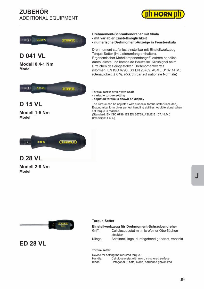
ZUBEHÖRADDITIONAL EQUIPMENT
D 28 VL
ED 28 VL
D 15 VLModell 1-5 NmModel
Modell 2-8 NmModel
Torque screw driver with scale- variable torque setting - adjusted torque is shown on displayThe Torque can be adjusted with a special torque setter (included).Ergonomical form gives perfect handling abilities. Audible signal when set torque is reached.(Standard: EN ISO 6798, BS EN 26789, ASME B 107.14.M.)(Precision: ± 6 %)
Torque-SetterEinstellwerkzeug für Drehmoment-SchraubendreherGriff: Celluloseacetat mit microfeiner Oberflächen- strukturKlinge: Achtkantklinge, durchgehend gehärtet, verzinkt
Torque setterDevice for setting the required torque.Handle: Celluloseacetat with micro structured surfaceBlade: Octogonal (8 flats) blade, hardened galvanized
D 041 VLModell 0,4-1 NmModel
Drehmoment-Schraubendreher mit Skala- mit variabler Einstellmöglichkeit - numerische Drehmoment-Anzeige in Fensterskala
Drehmoment stufenlos einstellbar mit Einstellwerkzeug Torque-Setter (im Lieferumfang enthalten).Ergonomischer Mehrkomponentengriff, extrem handlich durch leichte und kompakte Bauweise. Klicksignal beim Erreichen des eingestellten Drehmomentwertes.(Normen: EN ISO 6798, BS EN 26789, ASME B107.14.M.)(Genauigkeit: ± 6 %, rückführbar auf nationale Normale)
J9
J
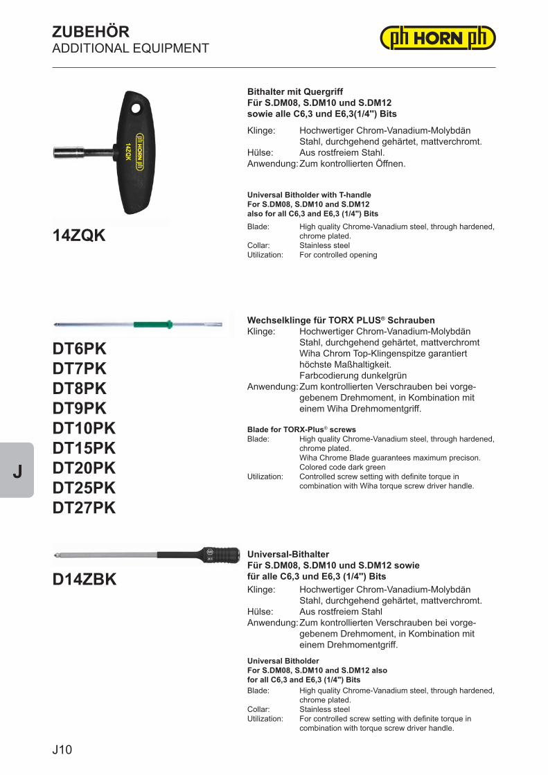
ZUBEHÖRADDITIONAL EQUIPMENT
D14ZBK
14ZQK
DT6PKDT7PKDT8PKDT9PKDT10PKDT15PKDT20PKDT25PKDT27PK
Wechselklinge für TORX PLUS® SchraubenKlinge: Hochwertiger Chrom-Vanadium-Molybdän Stahl, durchgehend gehärtet, mattverchromt Wiha Chrom Top-Klingenspitze garantiert höchste Maßhaltigkeit. Farbcodierung dunkelgrün Anwendung: Zum kontrollierten Verschrauben bei vorge- gebenem Drehmoment, in Kombination mit einem Wiha Drehmomentgriff.
Blade for TORX-Plus® screwsBlade: High quality Chrome-Vanadium steel, through hardened, chrome plated. Wiha Chrome Blade guarantees maximum precison. Colored code dark greenUtilization: Controlled screw setting with definite torque in combination with Wiha torque screw driver handle.
Bithalter mit QuergriffFür S.DM08, S.DM10 und S.DM12sowie alle C6,3 und E6,3(1/4'') Bits
Klinge: Hochwertiger Chrom-Vanadium-Molybdän Stahl, durchgehend gehärtet, mattverchromt.Hülse: Aus rostfreiem Stahl.Anwendung: Zum kontrollierten Öffnen.
Universal Bitholder with T-handleFor S.DM08, S.DM10 and S.DM12 also for all C6,3 and E6,3 (1/4") BitsBlade: High quality Chrome-Vanadium steel, through hardened, chrome plated.Collar: Stainless steelUtilization: For controlled opening
Universal-BithalterFür S.DM08, S.DM10 und S.DM12 sowiefür alle C6,3 und E6,3 (1/4'') BitsKlinge: Hochwertiger Chrom-Vanadium-Molybdän Stahl, durchgehend gehärtet, mattverchromt.Hülse: Aus rostfreiem StahlAnwendung: Zum kontrollierten Verschrauben bei vorge- gebenem Drehmoment, in Kombination mit einem Drehmomentgriff.
Universal Bitholder For S.DM08, S.DM10 and S.DM12 alsofor all C6,3 and E6,3 (1/4") BitsBlade: High quality Chrome-Vanadium steel, through hardened, chrome plated.Collar: Stainless steelUtilization: For controlled screw setting with definite torque in combination with torque screw driver handle.
J10
J
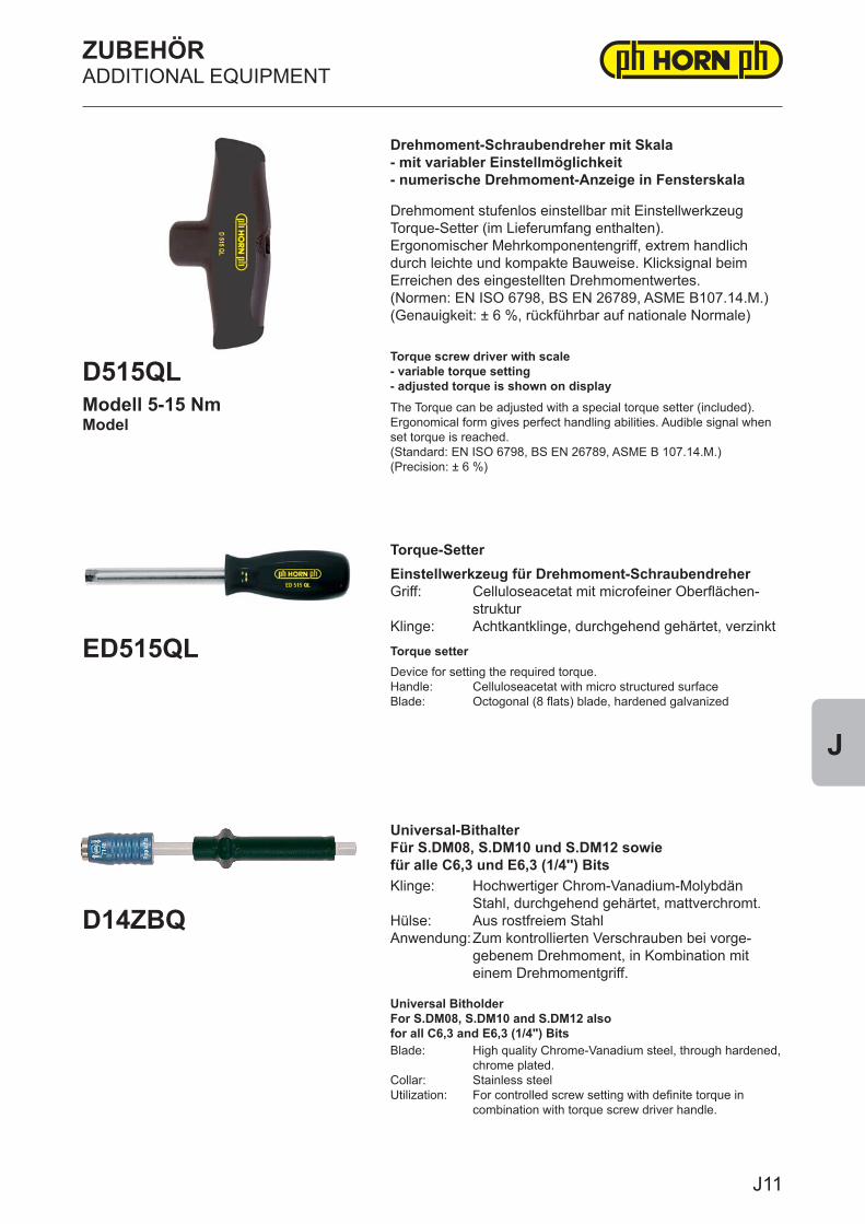
ZUBEHÖRADDITIONAL EQUIPMENT
D515QL
D14ZBQ
ED515QL
Modell 5-15 NmModel
Drehmoment-Schraubendreher mit Skala- mit variabler Einstellmöglichkeit - numerische Drehmoment-Anzeige in Fensterskala
Drehmoment stufenlos einstellbar mit Einstellwerkzeug Torque-Setter (im Lieferumfang enthalten).Ergonomischer Mehrkomponentengriff, extrem handlich durch leichte und kompakte Bauweise. Klicksignal beim Erreichen des eingestellten Drehmomentwertes.(Normen: EN ISO 6798, BS EN 26789, ASME B107.14.M.)(Genauigkeit: ± 6 %, rückführbar auf nationale Normale)
Torque screw driver with scale- variable torque setting - adjusted torque is shown on displayThe Torque can be adjusted with a special torque setter (included).Ergonomical form gives perfect handling abilities. Audible signal when set torque is reached.(Standard: EN ISO 6798, BS EN 26789, ASME B 107.14.M.)(Precision: ± 6 %)
Torque-SetterEinstellwerkzeug für Drehmoment-SchraubendreherGriff: Celluloseacetat mit microfeiner Oberflächen- strukturKlinge: Achtkantklinge, durchgehend gehärtet, verzinkt
Torque setterDevice for setting the required torque.Handle: Celluloseacetat with micro structured surfaceBlade: Octogonal (8 flats) blade, hardened galvanized
Universal-BithalterFür S.DM08, S.DM10 und S.DM12 sowiefür alle C6,3 und E6,3 (1/4'') BitsKlinge: Hochwertiger Chrom-Vanadium-Molybdän Stahl, durchgehend gehärtet, mattverchromt.Hülse: Aus rostfreiem StahlAnwendung: Zum kontrollierten Verschrauben bei vorge- gebenem Drehmoment, in Kombination mit einem Drehmomentgriff.
Universal Bitholder For S.DM08, S.DM10 and S.DM12 alsofor all C6,3 and E6,3 (1/4") BitsBlade: High quality Chrome-Vanadium steel, through hardened, chrome plated.Collar: Stainless steelUtilization: For controlled screw setting with definite torque in combination with torque screw driver handle.
J11
J
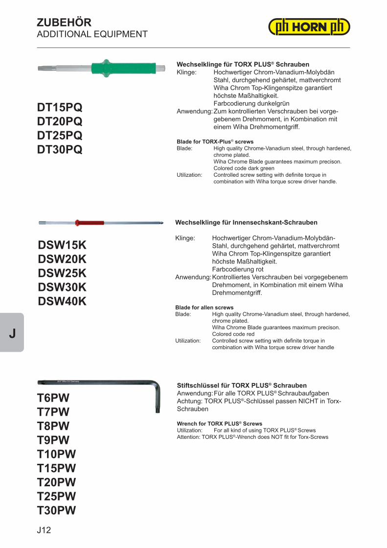
ZUBEHÖRADDITIONAL EQUIPMENT
DT15PQDT20PQDT25PQDT30PQ
T6PWT7PWT8PWT9PWT10PWT15PWT20PWT25PWT30PW
Wechselklinge für TORX PLUS® SchraubenKlinge: Hochwertiger Chrom-Vanadium-Molybdän Stahl, durchgehend gehärtet, mattverchromt Wiha Chrom Top-Klingenspitze garantiert höchste Maßhaltigkeit. Farbcodierung dunkelgrün Anwendung: Zum kontrollierten Verschrauben bei vorge- gebenem Drehmoment, in Kombination mit einem Wiha Drehmomentgriff.
Blade for TORX-Plus® screwsBlade: High quality Chrome-Vanadium steel, through hardened, chrome plated. Wiha Chrome Blade guarantees maximum precison. Colored code dark greenUtilization: Controlled screw setting with definite torque in combination with Wiha torque screw driver handle.
Stiftschlüssel für TORX PLUS® SchraubenAnwendung: Für alle TORX PLUS® SchraubaufgabenAchtung: TORX PLUS®-Schlüssel passen NICHT in Torx-Schrauben
Wrench for TORX PLUS® ScrewsUtilization: For all kind of using TORX PLUS® ScrewsAttention: TORX PLUS®-Wrench does NOT fit for Torx-Screws
Wechselklinge für Innensechskant-Schrauben Klinge: Hochwertiger Chrom-Vanadium-Molybdän- Stahl, durchgehend gehärtet, mattverchromt Wiha Chrom Top-Klingenspitze garantiert höchste Maßhaltigkeit. Farbcodierung rot Anwendung: Kontrolliertes Verschrauben bei vorgegebenem Drehmoment, in Kombination mit einem Wiha Drehmomentgriff. Blade for allen screwsBlade: High quality Chrome-Vanadium steel, through hardened, chrome plated. Wiha Chrome Blade guarantees maximum precison. Colored code redUtilization: Controlled screw setting with definite torque in combination with Wiha torque screw driver handle
DSW15KDSW20KDSW25KDSW30KDSW40K
J12
J
INDEX
TypType
SeitePage
105 D9,D11,D13,E12,E14,F8107 G2108 G7111 G12114 G17116 G20125 G11145 G19210 H1213 H8-H11214 H12218 H2,H4219 H6225 H7226 H5229 H14257 H13B105 D10,F3-F7B107 G1B108 G3-G4B108KM G5-G6B111 G8-G10B114 G13-G15B116 G18-G19BU105 F5CCGT A8-A13CCGW A14-A16,D4CPGT A17-A19CPGW A20-A22DCGT A23-A26DCGW A27-A28
TypType
SeitePage
DSFD C9DSFF.MD E2DSFN C7DSFU C8DSK C2DSK.MD E3DST C3-C5DSUD C6DTM B2DTS B3H117 D6HC105 D8HC114 G16M117 E8M117K E4M117P E6,E11M117U E7NH105 D12,E13RCGT A29RCGW A30RPGT A31RPGW A32S117 D7,E5,E9-E10,E12SCGT A33-A36SCGW A37-A38TCGT A39-A43TCGW A44-A46VBGT A47VBGW A48VCGT A49-A50VCGW A51,D5

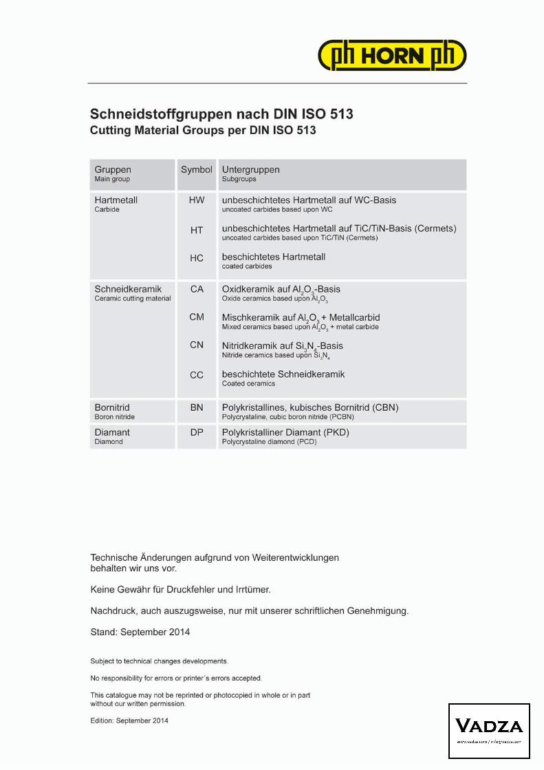


![PCD (2) 04.07.2016.ppt [Kompatibilit tsmodus]) · 3 Cytochrom c-Freisetzung Durch Caspase-Aktivierung Aktivierung Apoptose-spezifischer Endonucleasen Molekulare Merkmale der Apoptose](https://img.pdfslide.org/doc/110x75/5d49631588c9933f6b8b87b4/pcd-2-04072016ppt-kompatibilit-tsmodus-3-cytochrom-c-freisetzung-durch.jpg)