Embed Size (px)
Citation preview
Dell™ Systems
Installing the SCSI Backplane
Daughter Card
安装 SCSI 背板子卡
Installation de la carte fille
de fond de panier SCSI
Installieren der SCSI-Rückwandplatinen-
Tochterkarte
SCSI バックプレーンドータ
カードの取り付け
SCSI 후면판 보조 카드 설치
Instalación de la tarjeta secundaria
de plano posterior SCSI
w w w . d e l l . c o m | s u p p o r t . d e l l . c o m

Dell™ Systems
Installing the SCSI Backplane
Daughter Card
w w w . d e l l . c o m | s u p p o r t . d e l l . c o m
Notes, Notices, and Cautions
NOTE: A NOTE indicates important information that helps you make better use of your computer.
NOTICE: A NOTICE indicates either potential damage to hardware or loss of data and tells you how to avoid
the problem.
CAUTION: A CAUTION indicates a potential for property damage, personal injury, or death.
____________________
Information in this document is subject to change without notice.© 2004 Dell Inc. All rights reserved.
Reproduction in any manner whatsoever without the written permission of Dell Inc. is strictly forbidden.
Trademarks used in this text: Dell, the DELL logo, and PowerEdge are trademarks of Dell Inc.
Other trademarks and trade names may be used in this document to refer to either the entities claiming the marks and names or their products. Dell Inc. disclaims any proprietary interest in trademarks and trade names other than its own.
July 2004 P/N F6589 Rev. A00
This document provides information about how to configure the split SCSI backplane in your Dell™ PowerEdge™ 2800 or 2850 system by installing a backplane daughter card. In a split backplane configuration, the hard-drives are arranged in two separate groups of drives.
CAUTION: Only trained service technicians are authorized to remove the system cover and access any
of the components inside the system. See your Product Information Guide for complete information
about safety precautions, working inside the computer, and protecting against electrostatic discharge.
NOTE: See your Installation and Troubleshooting Guide for detailed instructions on removing
or replacing components.
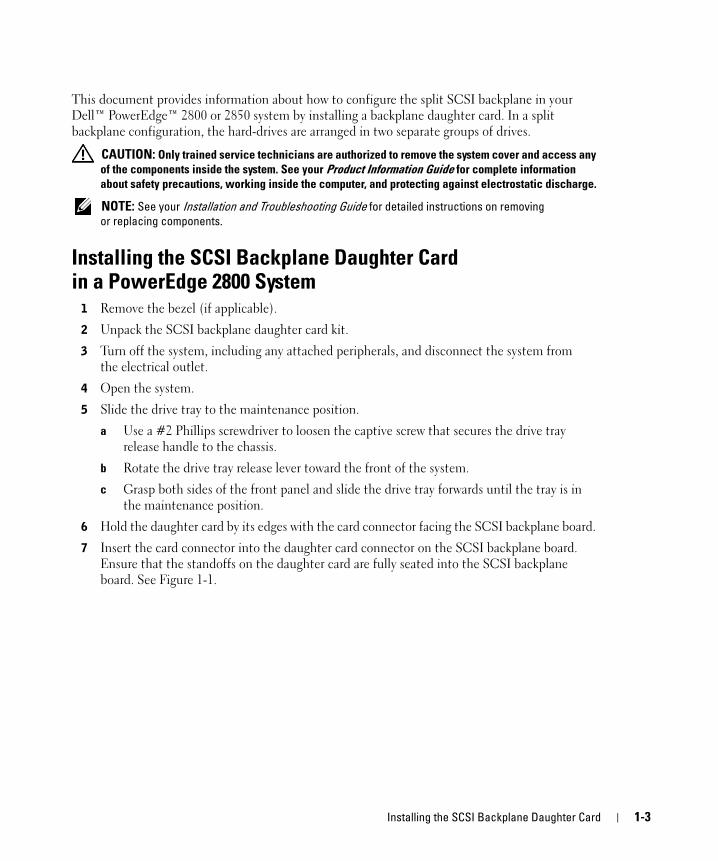
Installing the SCSI Backplane Daughter Card in a PowerEdge 2800 System1 Remove the bezel (if applicable).
2 Unpack the SCSI backplane daughter card kit.
3 Turn off the system, including any attached peripherals, and disconnect the system from the electrical outlet.
4 Open the system.
5 Slide the drive tray to the maintenance position.
a Use a #2 Phillips screwdriver to loosen the captive screw that secures the drive tray release handle to the chassis.
b Rotate the drive tray release lever toward the front of the system.
c Grasp both sides of the front panel and slide the drive tray forwards until the tray is in the maintenance position.
6 Hold the daughter card by its edges with the card connector facing the SCSI backplane board.
7 Insert the card connector into the daughter card connector on the SCSI backplane board. Ensure that the standoffs on the daughter card are fully seated into the SCSI backplane board. See Figure 1-1.
Installing the SCSI Backplane Daughter Card 1-3
ww
w.d
ell
.co
m |
su
pp
or
t.d
ell
.co
m
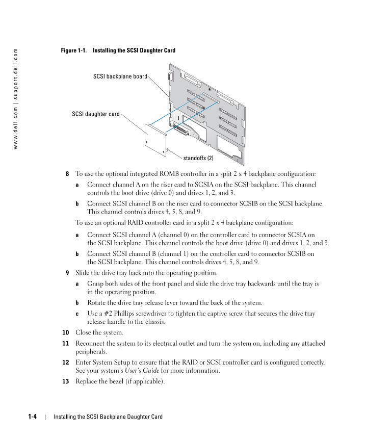
Figure 1-1. Installing the SCSI Daughter Card8 To use the optional integrated ROMB controller in a split 2 x 4 backplane configuration:
a Connect channel A on the riser card to SCSIA on the SCSI backplane. This channel controls the boot drive (drive 0) and drives 1, 2, and 3.
b Connect SCSI channel B on the riser card to connector SCSIB on the SCSI backplane. This channel controls drives 4, 5, 8, and 9.
To use an optional RAID controller card in a split 2 x 4 backplane configuration:
a Connect SCSI channel A (channel 0) on the controller card to connector SCSIA on the SCSI backplane. This channel controls the boot drive (drive 0) and drives 1, 2, and 3.
b Connect SCSI channel B (channel 1) on the controller card to connector SCSIB on the SCSI backplane. This channel controls drives 4, 5, 8, and 9.
9 Slide the drive tray back into the operating position.
a Grasp both sides of the front panel and slide the drive tray backwards until the tray is in the operating position.
b Rotate the drive tray release lever toward the back of the system.
c Use a #2 Phillips screwdriver to tighten the captive screw that secures the drive tray release handle to the chassis.
10 Close the system.
11 Reconnect the system to its electrical outlet and turn the system on, including any attached peripherals.
12 Enter System Setup to ensure that the RAID or SCSI controller card is configured correctly. See your system’s User’s Guide for more information.
13 Replace the bezel (if applicable).
SCSI daughter card
SCSI backplane board
standoffs (2)
1-4 Installing the SCSI Backplane Daughter Card
Installing the SCSI Backplane Daughter Card in a PowerEdge 2850 System1 Unpack the SCSI backplane board daughter card kit.
2 Turn off the system, including any attached peripherals, and disconnect the system from the electrical outlet.
3 Remove the bezel (if applicable).
4 Open the system.
5 Grasp the plastic tab on the back of the control panel cable and pull the cable connector away from the backplane connector. See Figure 1-2.
NOTE: If you pull on the control panel cable harness, you may damage the harness.
The SCSI backplane daughter card connector and card guide are located in the compartment below the control panel cable.
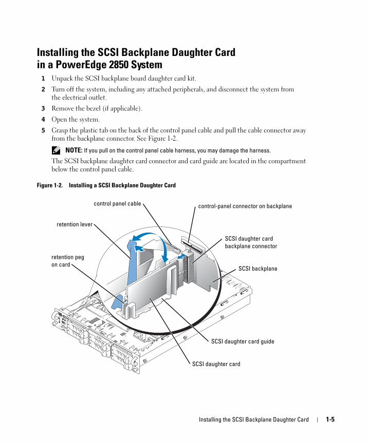
Figure 1-2. Installing a SCSI Backplane Daughter Card
SCSI daughter card
SCSI backplane
retention lever
SCSI daughter card guide
retention peg
on card
control panel cable
SCSI daughter card
backplane connector
control-panel connector on backplane
Installing the SCSI Backplane Daughter Card 1-5

ww
w.d
ell
.co
m |
su
pp
or
t.d
ell
.co
m
6 The daughter card fits between the sides of the card guide. To install the daughter card in the card guide and to connect it to the backplane connector:a Ensure that the retention lever is in the open position.
b Hold the daughter card by its edges with the card connector facing the SCSI backplane and the retention peg facing the retention lever. See Figure 1-2.
c Lower the card into the card guide.
d Close the retention lever to slide the daughter card into the SCSI backplane connector and lock the card into place. See Figure 1-2.
7 Rotate the drive bay retraction bar toward the front of the system. See Figure 1-3.
Figure 1-3. Drive Bay Retraction Bar
8 Reconnect the control panel cable to its backplane connector. See Figure 1-2.
9 To use the optional integrated ROMB controller in a split backplane configuration:
a Connect channel A on the riser card to SCSIA on the SCSI backplane. This channel controls the boot drive (drive 0) and drive 1.
b Connect SCSI channel B on the riser card to connector SCSIB on the SCSI backplane. This channel controls drives 2 through 5.
drive bay retraction bar
1-6 Installing the SCSI Backplane Daughter Card
To use the optional RAID controller card in a split backplane configuration:
a Connect SCSI channel A (channel 0) on the controller card to connector SCSIA on the SCSI backplane. This channel controls the boot drive (drive 0) and drive 1.
b Connect SCSI channel B (channel 1) on the controller card to connector SCSIB on the SCSI backplane. This channel controls drives 2 through 5.
NOTE: If a cable is connected to the SCSIB backplane connector, the SCSI backplane daughter
card must be installed to activate the 2/4 split backplane configuration. Otherwise, the system will
display an error message.
10 Rotate the drive bay retraction bar toward the back of the system.
11 Close the system.
12 Enter System Setup to ensure that the RAID or SCSI controller card is configured correctly. See your system’s User’s Guide for more information.
13 Replace the bezel (if applicable).
Installing the SCSI Backplane Daughter Card 1-7
ww
w.d
ell
.co
m |
su
pp
or
t.d
ell
.co
m
1-8 Installing the SCSI Backplane Daughter Card
Dell™ 系统
安装 SCSI 背板子卡
w w w . d e l l . c o m | s u p p o r t . d e l l . c o m
注、注意和警告 注: 注表示可以帮助您更好地使用计算机的重要信息。
注意: 注意表示可能会损坏硬件或导致数据丢失,并告诉您如何避免此类问题。
警告: 警告表示存在可能导致财产损失、人身伤害或死亡的潜在危险。
____________________
本文中的信息如有更改,恕不另行通知。
© 2004 Dell Inc.。保留所有权利。
未经 Dell Inc. 书面许可,不得以任何方式进行复制。
本文件中使用的商标:Dell、 DELL 徽标和 PowerEdge 是 Dell Inc. 的商标。
本文件中述及的其它商标和产品名称是指拥有相应商标和名称的公司或其制造的产品。
Dell Inc. 对本公司的商标和产品名称之外的其它商标和产品名称不拥有任何专有权。
2004 年 7 月 P/N F6589 Rev. A00
本文档提供了如何在 Dell™ PowerEdge™ 2800 或 2850 系统中通过安装背板子卡来配置分割式 SCSI 背板的信息。在分割式背板配置中,硬盘驱动器分为两个不同的驱动器组。
警告: 只有经过培训的维修技术人员才能卸下主机盖并拆装系统内部的任何组件。有关安全预
防措施、拆装计算机内部组件以及防止静电释放的完整信息,请参阅《产品信息指南》。
注: 有关卸下或装回组件的详情,请参阅《安装与故障排除指南》。
在 PowerEdge 2800 系统中安装 SCSI 背板子卡1 如果需要,请卸下挡板。
2 拆开 SCSI 背板子卡套件的包装。
3 关闭系统电源(包括连接的任何外围设备),然后断开系统与电源插座的连接。
4 打开系统外壳。
5 将驱动器托架滑动到维护位置。
a 使用 2 号梅花槽螺丝刀,松开将驱动器托架释放手柄固定到机箱的固定螺钉。
b 朝系统的正面转动驱动器托架释放拉杆。
c 抓住前面板的两端,将驱动器托架向前滑动,直到托架处于维护位置。
6 抓住子卡边缘,卡连接器朝向 SCSI 背板。
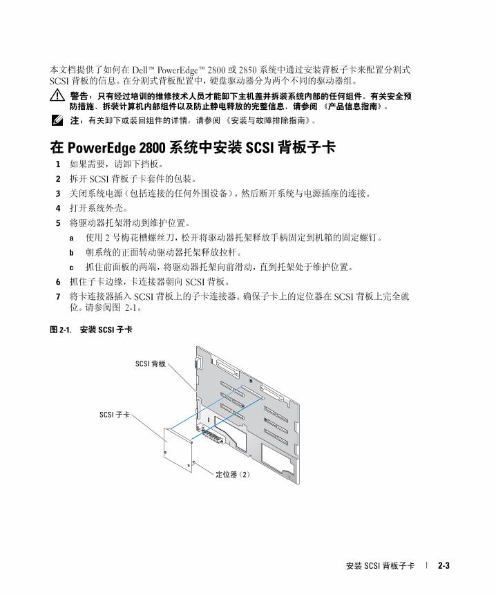
7 将卡连接器插入 SCSI 背板上的子卡连接器。确保子卡上的定位器在 SCSI 背板上完全就位。请参阅图 2-1。
图 2-1. 安装 SCSI 子卡
SCSI 子卡
SCSI 背板
定位器(2)
安装 SCSI 背板子卡 2-3
ww
w.d
ell
.co
m |
su
pp
or
t.d
ell
.co
m
8 在 2 x 4 分割式背板配置中使用可选集成 ROMB 控制器:a 将提升卡上的通道 A 连接到 SCSI 背板上的 SCSIA。此通道控制引导驱动器(驱动器 0)和驱动器 1、2、3。
b 将提升卡上的 SCSI 通道 B 连接到 SCSI 背板上的 SCSIB 连接器。此通道控制驱动器 4、5、8、9。
在 2 x 4 分割式背板配置中使用可选 RAID 控制器卡:
a 将控制器卡上的 SCSI 通道 A(通道 0)连接到 SCSI 背板上的 SCSIA 连接器。此通道控制引导驱动器(驱动器 0)和驱动器 1、2、3。
b 将控制器卡上的 SCSI 通道 B(通道 1)连接到 SCSI 背板上的 SCSIB 连接器。此通道控制驱动器 4、5、8、9。
9 将驱动器托架向后滑动到操作位置。
a 抓住前面板的两端,将驱动器托架向后滑动,直到托架处于操作位置。
b 朝系统的背面转动驱动器托架释放拉杆。
c 使用 2 号梅花槽螺丝刀,拧紧固定驱动器托架释放手柄和机箱的固定螺钉。
10 合上系统外壳。
11 将系统(包括连接的任何外围设备)重新连接至电源插座,然后开机。
12 输入系统设置,确保 RAID 或 SCSI 控制器卡配置正确无误。有关详情,请参阅系统的《用户指南》。
13 如果需要,请装回挡板。
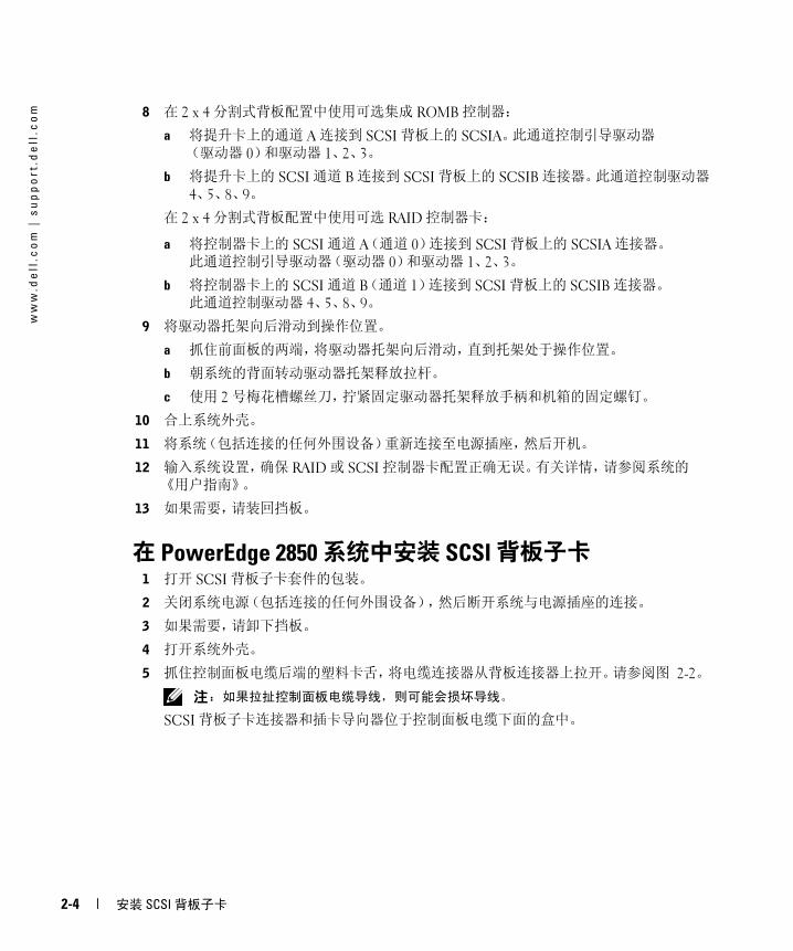
在 PowerEdge 2850 系统中安装 SCSI 背板子卡1 打开 SCSI 背板子卡套件的包装。
2 关闭系统电源(包括连接的任何外围设备),然后断开系统与电源插座的连接。
3 如果需要,请卸下挡板。
4 打开系统外壳。
5 抓住控制面板电缆后端的塑料卡舌,将电缆连接器从背板连接器上拉开。请参阅图 2-2。
注: 如果拉扯控制面板电缆导线,则可能会损坏导线。
SCSI 背板子卡连接器和插卡导向器位于控制面板电缆下面的盒中。
2-4 安装 SCSI 背板子卡
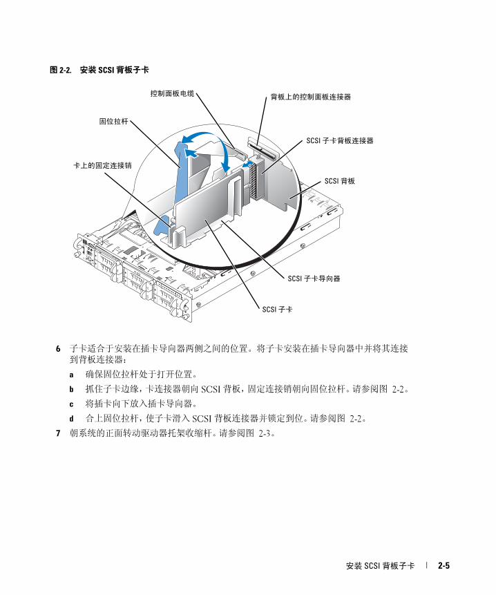
图 2-2. 安装 SCSI 背板子卡
6 子卡适合于安装在插卡导向器两侧之间的位置。将子卡安装在插卡导向器中并将其连接
到背板连接器:
a 确保固位拉杆处于打开位置。
b 抓住子卡边缘,卡连接器朝向 SCSI 背板,固定连接销朝向固位拉杆。请参阅图 2-2。
c 将插卡向下放入插卡导向器。
d 合上固位拉杆,使子卡滑入 SCSI 背板连接器并锁定到位。请参阅图 2-2。
7 朝系统的正面转动驱动器托架收缩杆。请参阅图 2-3。
SCSI 子卡
SCSI 背板
固位拉杆
SCSI 子卡导向器
卡上的固定连接销
控制面板电缆
SCSI 子卡背板连接器
背板上的控制面板连接器
安装 SCSI 背板子卡 2-5
ww
w.d
ell
.co
m |
su
pp
or
t.d
ell
.co
m
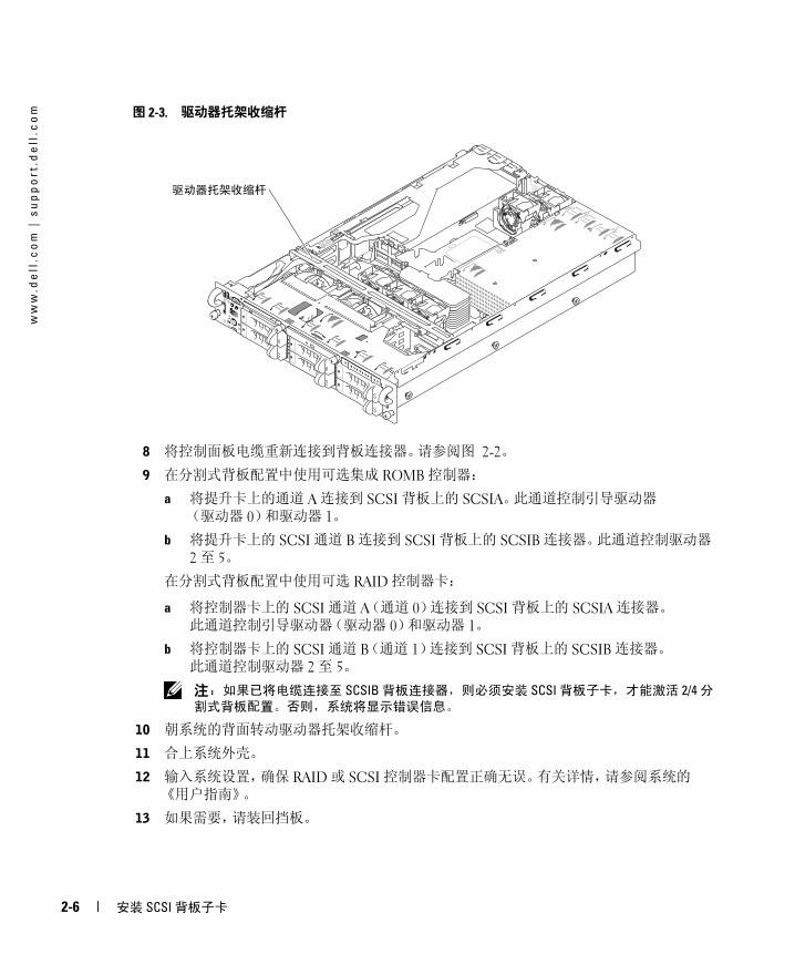
图 2-3. 驱动器托架收缩杆8 将控制面板电缆重新连接到背板连接器。请参阅图 2-2。
9 在分割式背板配置中使用可选集成 ROMB 控制器:
a 将提升卡上的通道 A 连接到 SCSI 背板上的 SCSIA。此通道控制引导驱动器(驱动器 0)和驱动器 1。
b 将提升卡上的 SCSI 通道 B 连接到 SCSI 背板上的 SCSIB 连接器。此通道控制驱动器 2 至 5。
在分割式背板配置中使用可选 RAID 控制器卡:
a 将控制器卡上的 SCSI 通道 A(通道 0)连接到 SCSI 背板上的 SCSIA 连接器。此通道控制引导驱动器(驱动器 0)和驱动器 1。
b 将控制器卡上的 SCSI 通道 B(通道 1)连接到 SCSI 背板上的 SCSIB 连接器。此通道控制驱动器 2 至 5。
注: 如果已将电缆连接至 SCSIB 背板连接器,则必须安装 SCSI 背板子卡,才能激活 2/4 分
割式背板配置。否则,系统将显示错误信息。
10 朝系统的背面转动驱动器托架收缩杆。
11 合上系统外壳。
12 输入系统设置,确保 RAID 或 SCSI 控制器卡配置正确无误。有关详情,请参阅系统的《用户指南》。
13 如果需要,请装回挡板。
驱动器托架收缩杆
2-6 安装 SCSI 背板子卡
Systèmes Dell™
Installation de la carte fille
de fond de panier SCSI
w w w . d e l l . c o m | s u p p o r t . d e l l . c o m
Remarques, avis et précautions
REMARQUE : une REMARQUE indique des informations importantes qui peuvent vous aider à mieux utiliser
l'ordinateur.
AVIS : un AVIS vous avertit d'un risque de dommage matériel ou de perte de données et vous indique comment éviter
le problème.
PRÉCAUTION : une PRÉCAUTION indique un risque potentiel d'endommagement du matériel, de blessure corporelle ou de mort.
____________________
Les informations contenues dans ce document peuvent être modifiées sans préavis.© 2004 Dell Inc. Tous droits réservés.
La reproduction de ce document de quelque manière que ce soit sans l'autorisation écrite de Dell Inc. est strictement interdite.
Marques utilisées dans ce document : Dell, le logo DELL et PowerEdge sont des marques de Dell Inc.
Tous les autres noms de marques et marques commerciales utilisés dans ce document se rapportent aux sociétés propriétaires des marques et des noms de ces produits. Dell Inc. décline tout intérêt dans l'utilisation des marques déposées et des noms de marques ne lui appartenant pas.
Juillet 2004 P/N F6589 Rev. A00

Le présent document explique comment configurer un fond de panier SCSI partagé sur un système Dell™ PowerEdge™ 2800 ou 2850 en installant une carte fille de fond de panier. Cette configuration permet de diviser les disques durs en deux groupes séparés.
PRÉCAUTION : seuls les techniciens de maintenance qualifiés sont habilités à retirer le capot du système et à accéder aux composants du système. Consultez le Guide d'information sur le produit pour obtenir des informations détaillées sur les consignes de sécurité, les interventions dans l'ordinateur et la protection contre les décharges électrostatiques.
REMARQUE : consultez le Guide d'installation et de dépannage pour obtenir des instructions détaillées
sur le retrait ou le remplacement de composants.
Installation de la carte fille de fond de panier SCSI dans un système PowerEdge 28001 Retirez le cadre, si nécessaire.
2 Retirez le kit de la carte fille de fond de panier SCSI de son emballage.
3 Éteignez le système et les périphériques connectés, puis débranchez-le de la prise de courant.
4 Ouvrez le système.
5 Faites glisser le plateau des lecteurs pour le placer en position de maintenance.
a À l'aide d'un tournevis cruciforme n°2, desserrez la vis imperdable qui fixe la poignée de dégagement du plateau au châssis.
b Faites pivoter le levier de dégagement du plateau vers l'avant du système.
c Saisissez les deux côtés du panneau avant et faites glisser le plateau vers l'avant jusqu'à ce qu'il soit en position de maintenance.
6 Tenez la carte fille par les bords, son connecteur faisant face à la carte de fond de panier SCSI.
7 Insérez le connecteur de la carte dans le connecteur de carte fille du fond de panier SCSI. Vérifiez que les picots de la carte fille sont engagés à fond dans la carte de fond de panier SCSI. Voir la figure 3-1.
Installation de la carte fille de fond de panier SCSI 3-3
ww
w.d
ell
.co
m |
su
pp
or
t.d
ell
.co
m
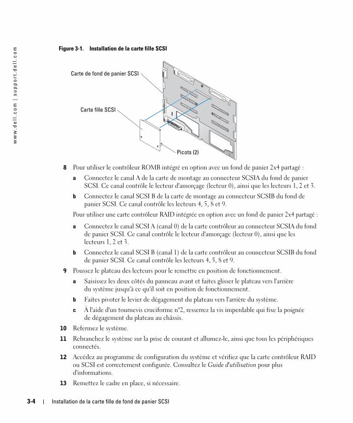
Figure 3-1. Installation de la carte fille SCSI8 Pour utiliser le contrôleur ROMB intégré en option avec un fond de panier 2x4 partagé :
a Connectez le canal A de la carte de montage au connecteur SCSIA du fond de panier SCSI. Ce canal contrôle le lecteur d'amorçage (lecteur 0), ainsi que les lecteurs 1, 2 et 3.
b Connectez le canal SCSI B de la carte de montage au connecteur SCSIB du fond de panier SCSI. Ce canal contrôle les lecteurs 4, 5, 8 et 9.
Pour utiliser une carte contrôleur RAID intégrée en option avec un fond de panier 2x4 partagé :
a Connectez le canal SCSI A (canal 0) de la carte contrôleur au connecteur SCSIA du fond de panier SCSI. Ce canal contrôle le lecteur d'amorçage (lecteur 0), ainsi que les lecteurs 1, 2 et 3.
b Connectez le canal SCSI B (canal 1) de la carte contrôleur au connecteur SCSIB du fond de panier SCSI. Ce canal contrôle les lecteurs 4, 5, 8 et 9.
9 Poussez le plateau des lecteurs pour le remettre en position de fonctionnement.
a Saisissez les deux côtés du panneau avant et faites glisser le plateau vers l'arrière du système jusqu'à ce qu'il soit en position de fonctionnement.
b Faites pivoter le levier de dégagement du plateau vers l'arrière du système.
c À l'aide d'un tournevis cruciforme n°2, resserrez la vis imperdable qui fixe la poignée de dégagement du plateau au châssis.
10 Refermez le système.
11 Rebranchez le système sur la prise de courant et allumez-le, ainsi que tous les périphériques connectés.
12 Accédez au programme de configuration du système et vérifiez que la carte contrôleur RAID ou SCSI est correctement configurée. Consultez le Guide d'utilisation pour plus d'informations.
13 Remettez le cadre en place, si nécessaire.
Carte fille SCSI
Carte de fond de panier SCSI
Picots (2)
3-4 Installation de la carte fille de fond de panier SCSI
Installation de la carte fille de fond de panier SCSI dans un système PowerEdge 28501 Retirez le kit de son emballage.
2 Éteignez le système et les périphériques connectés, puis débranchez-le de la prise de courant.
3 Retirez le cadre, si nécessaire.
4 Ouvrez le système.
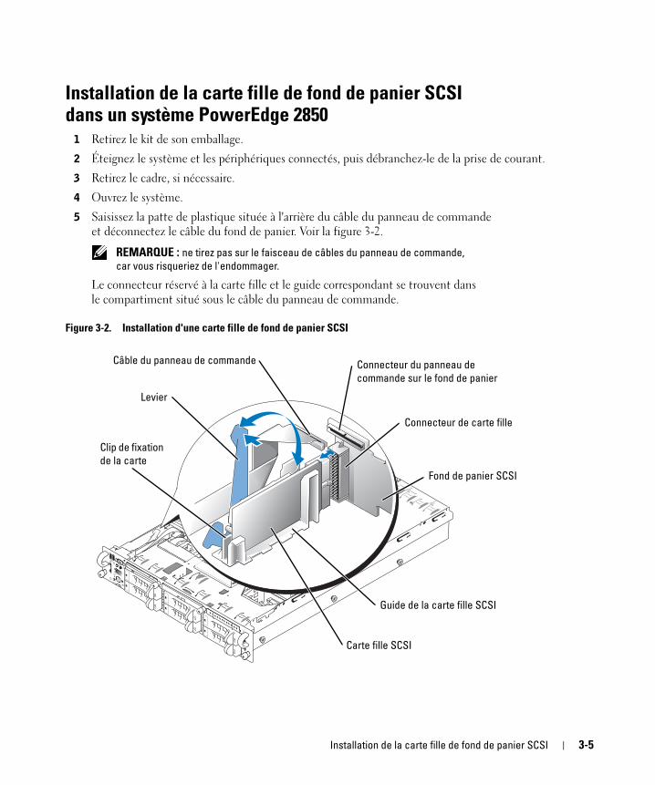
5 Saisissez la patte de plastique située à l'arrière du câble du panneau de commande et déconnectez le câble du fond de panier. Voir la figure 3-2.
REMARQUE : ne tirez pas sur le faisceau de câbles du panneau de commande,
car vous risqueriez de l'endommager.
Le connecteur réservé à la carte fille et le guide correspondant se trouvent dans le compartiment situé sous le câble du panneau de commande.
Figure 3-2. Installation d'une carte fille de fond de panier SCSI
Carte fille SCSI
Fond de panier SCSI
Levier
Guide de la carte fille SCSI
Clip de fixation
de la carte
Câble du panneau de commande
Connecteur de carte fille
Connecteur du panneau de
commande sur le fond de panier
Installation de la carte fille de fond de panier SCSI 3-5
ww
w.d
ell
.co
m |
su
pp
or
t.d
ell
.co
m
6 La carte fille se place entre les côtés du guide. Pour installer la carte fille dans le guide et l'insérer dans le connecteur approprié du fond de panier, procédez comme suit :a Vérifiez que le levier est ouvert.
b Tenez la carte fille par les bords, son connecteur faisant face au fond de panier SCSI. Le clip de fixation doit être du même côté que le levier. Voir la figure 3-2.
c Abaissez la carte dans le guide.
d Fermez le levier pour glisser la carte dans le connecteur du fond de panier SCSI et la maintenir en place. Voir la figure 3-2.
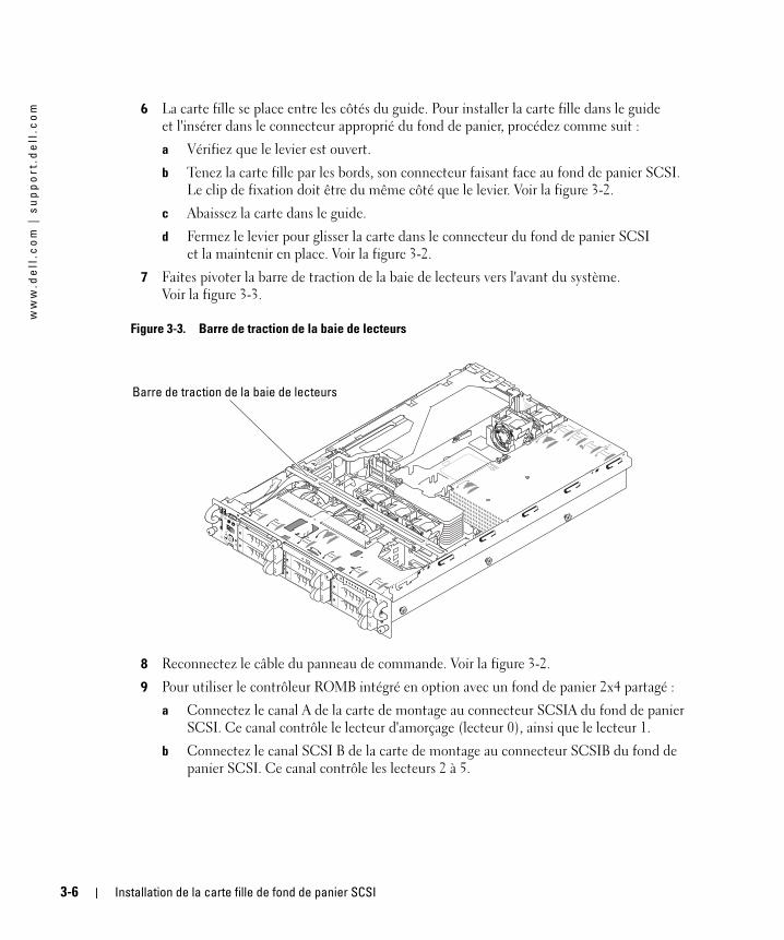
7 Faites pivoter la barre de traction de la baie de lecteurs vers l'avant du système. Voir la figure 3-3.
Figure 3-3. Barre de traction de la baie de lecteurs
8 Reconnectez le câble du panneau de commande. Voir la figure 3-2.
9 Pour utiliser le contrôleur ROMB intégré en option avec un fond de panier 2x4 partagé :
a Connectez le canal A de la carte de montage au connecteur SCSIA du fond de panier SCSI. Ce canal contrôle le lecteur d'amorçage (lecteur 0), ainsi que le lecteur 1.
b Connectez le canal SCSI B de la carte de montage au connecteur SCSIB du fond de panier SCSI. Ce canal contrôle les lecteurs 2 à 5.
Barre de traction de la baie de lecteurs
3-6 Installation de la carte fille de fond de panier SCSI
Pour utiliser la carte contrôleur RAID en option avec un fond de panier partagé :
a Connectez le canal SCSI A (canal 0) de la carte contrôleur au connecteur SCSIA du fond de panier SCSI. Ce canal contrôle le lecteur d'amorçage (lecteur 0), ainsi que le lecteur 1.
b Connectez le canal SCSI B (canal 1) de la carte contrôleur au connecteur SCSIB du fond de panier SCSI. Ce canal contrôle les lecteurs 2 à 5.
REMARQUE : si un câble est branché sur le connecteur SCSIB du fond de panier, la carte fille doit
être installée de manière à activer la configuration partagée 2/4. Dans le cas contraire, le système
affiche un message d'erreur.
10 Faites pivoter la barre de traction de la baie de lecteurs vers l'arrière du système.
11 Refermez le système.
12 Accédez au programme de configuration du système et vérifiez que la carte contrôleur RAID ou SCSI est correctement configurée. Consultez le Guide d'utilisation pour plus d'informations.
13 Remettez le cadre en place, si nécessaire.
Installation de la carte fille de fond de panier SCSI 3-7
ww
w.d
ell
.co
m |
su
pp
or
t.d
ell
.co
m
3-8 Installation de la carte fille de fond de panier SCSI
Dell™-Systeme
Installieren der SCSI-
Rückwandplatinen-
Tochterkarte
w w w . d e l l . c o m | s u p p o r t . d e l l . c o m
Anmerkungen, Hinweise und Vorsichtshinweise
ANMERKUNG: Eine ANMERKUNG macht auf wichtige Informationen aufmerksam, die Ihnen die Arbeit
mit dem Computer erleichtern.
HINWEIS: Ein HINWEIS warnt vor möglichen Beschädigungen der Hardware oder Datenverlust und zeigt,
wie diese vermieden werden können.
VORSICHT: VORSICHT weist auf Gefahrenquellen hin, die materielle Schäden, Verletzungen oder sogar den Tod
von Personen zur Folge haben können.
____________________
Irrtümer und technische Änderungen vorbehalten.© 2004 Dell Inc. Alle Rechte vorbehalten.
Eine Reproduktion dieses Dokuments in jeglicher Form ohne schriftliche Genehmigung von Dell Inc. ist streng verboten.
Marken in diesem Text: Dell, das DELL-Firmenzeichen und PowerEdge sind Marken der Dell Inc.
Andere in diesem Dokument möglicherweise verwendete Marken und Handelsbezeichnungen sind unter Umständen Marken und Namen der entsprechenden Firmen oder ihrer Produkte. Dell Inc. erhebt keinen Anspruch auf Marken und Handelsbezeichnungen mit Ausnahme der eigenen.
Juli 2004 P/N F6589 Rev. A00
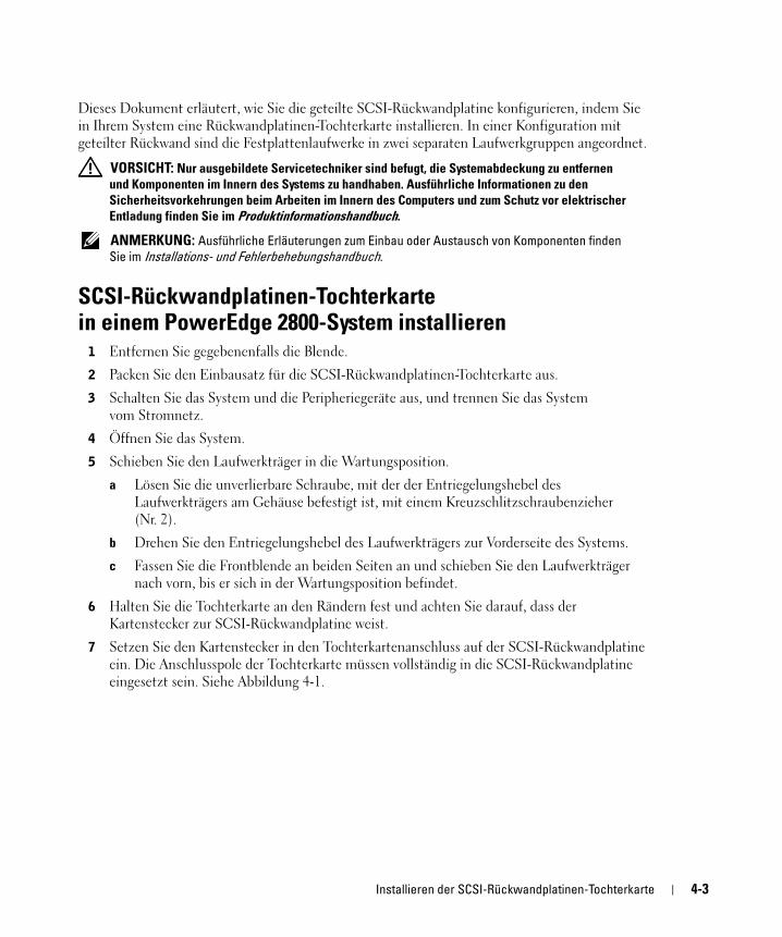
Dieses Dokument erläutert, wie Sie die geteilte SCSI-Rückwandplatine konfigurieren, indem Sie in Ihrem System eine Rückwandplatinen-Tochterkarte installieren. In einer Konfiguration mit geteilter Rückwand sind die Festplattenlaufwerke in zwei separaten Laufwerkgruppen angeordnet.
VORSICHT: Nur ausgebildete Servicetechniker sind befugt, die Systemabdeckung zu entfernen
und Komponenten im Innern des Systems zu handhaben. Ausführliche Informationen zu den
Sicherheitsvorkehrungen beim Arbeiten im Innern des Computers und zum Schutz vor elektrischer
Entladung finden Sie im Produktinformationshandbuch.
ANMERKUNG: Ausführliche Erläuterungen zum Einbau oder Austausch von Komponenten finden
Sie im Installations- und Fehlerbehebungshandbuch.
SCSI-Rückwandplatinen-Tochterkarte in einem PowerEdge 2800-System installieren1 Entfernen Sie gegebenenfalls die Blende.
2 Packen Sie den Einbausatz für die SCSI-Rückwandplatinen-Tochterkarte aus.
3 Schalten Sie das System und die Peripheriegeräte aus, und trennen Sie das System vom Stromnetz.
4 Öffnen Sie das System.
5 Schieben Sie den Laufwerkträger in die Wartungsposition.
a Lösen Sie die unverlierbare Schraube, mit der der Entriegelungshebel des Laufwerkträgers am Gehäuse befestigt ist, mit einem Kreuzschlitzschraubenzieher (Nr. 2).
b Drehen Sie den Entriegelungshebel des Laufwerkträgers zur Vorderseite des Systems.
c Fassen Sie die Frontblende an beiden Seiten an und schieben Sie den Laufwerkträger nach vorn, bis er sich in der Wartungsposition befindet.
6 Halten Sie die Tochterkarte an den Rändern fest und achten Sie darauf, dass der Kartenstecker zur SCSI-Rückwandplatine weist.
7 Setzen Sie den Kartenstecker in den Tochterkartenanschluss auf der SCSI-Rückwandplatine ein. Die Anschlusspole der Tochterkarte müssen vollständig in die SCSI-Rückwandplatine eingesetzt sein. Siehe Abbildung 4-1.
Installieren der SCSI-Rückwandplatinen-Tochterkarte 4-3
ww
w.d
ell
.co
m |
su
pp
or
t.d
ell
.co
m
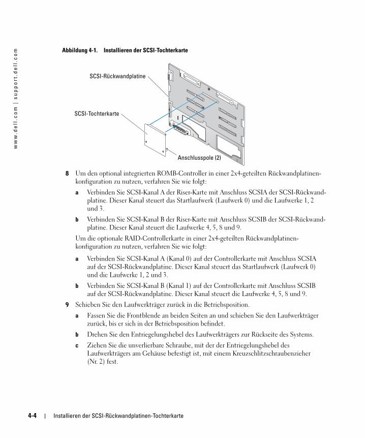
Abbildung 4-1. Installieren der SCSI-Tochterkarte8 Um den optional integrierten ROMB-Controller in einer 2x4-geteilten Rückwandplatinen-konfiguration zu nutzen, verfahren Sie wie folgt:
a Verbinden Sie SCSI-Kanal A der Riser-Karte mit Anschluss SCSIA der SCSI-Rückwand-platine. Dieser Kanal steuert das Startlaufwerk (Laufwerk 0) und die Laufwerke 1, 2 und 3.
b Verbinden Sie SCSI-Kanal B der Riser-Karte mit Anschluss SCSIB der SCSI-Rückwand-platine. Dieser Kanal steuert die Laufwerke 4, 5, 8 und 9.
Um die optionale RAID-Controllerkarte in einer 2x4-geteilten Rückwandplatinen-konfiguration zu nutzen, verfahren Sie wie folgt:
a Verbinden Sie SCSI-Kanal A (Kanal 0) auf der Controllerkarte mit Anschluss SCSIA auf der SCSI-Rückwandplatine. Dieser Kanal steuert das Startlaufwerk (Laufwerk 0) und die Laufwerke 1, 2 und 3.
b Verbinden Sie SCSI-Kanal B (Kanal 1) auf der Controllerkarte mit Anschluss SCSIB auf der SCSI-Rückwandplatine. Dieser Kanal steuert die Laufwerke 4, 5, 8 und 9.
9 Schieben Sie den Laufwerkträger zurück in die Betriebsposition.
a Fassen Sie die Frontblende an beiden Seiten an und schieben Sie den Laufwerkträger zurück, bis er sich in der Betriebsposition befindet.
b Drehen Sie den Entriegelungshebel des Laufwerkträgers zur Rückseite des Systems.
c Ziehen Sie die unverlierbare Schraube, mit der der Entriegelungshebel des Laufwerkträgers am Gehäuse befestigt ist, mit einem Kreuzschlitzschraubenzieher (Nr. 2) fest.
SCSI-Tochterkarte
SCSI-Rückwandplatine
Anschlusspole (2)
4-4 Installieren der SCSI-Rückwandplatinen-Tochterkarte
10 Schließen Sie das System.
11 Schließen Sie das System wieder an das Stromnetz an und schalten Sie das System und alle angeschlossenen Peripheriegeräte ein.
12 Rufen Sie das System-Setup auf, um sich zu vergewissern, dass die RAID- bzw. SCSI-Controllerkarte korrekt konfiguriert wurde. Weitere Informationen hierzu finden Sie im Benutzerhandbuch Ihres Systems.
13 Bringen Sie gegebenenfalls die Blende wieder an.
SCSI-Rückwandplatinen-Tochterkarte in einem PowerEdge 2850-System installieren1 Packen Sie den Tochterkarten-Einbausatz für die SCSI-Rückwandplatine aus.
2 Schalten Sie das System und die Peripheriegeräte aus, und trennen Sie das System vom Stromnetz.
3 Entfernen Sie gegebenenfalls die Blende.
4 Öffnen Sie das System.
5 Ziehen Sie das Systemsteuerungskabel vom Anschluss auf der Rückwandplatine ab, indem sie den Plastikstecker am Kabelende anfassen. Siehe Abbildung 4-2.
ANMERKUNG: Ziehen Sie nicht am Kabelbaum selbst, da Sie diesen sonst beschädigen könnten.
Der Anschluss und die Führungsschiene für die SCSI-Rückwandplatinen-Tochterkarte befinden sich unter dem Systemsteuerungskabel.
Installieren der SCSI-Rückwandplatinen-Tochterkarte 4-5
ww
w.d
ell
.co
m |
su
pp
or
t.d
ell
.co
m
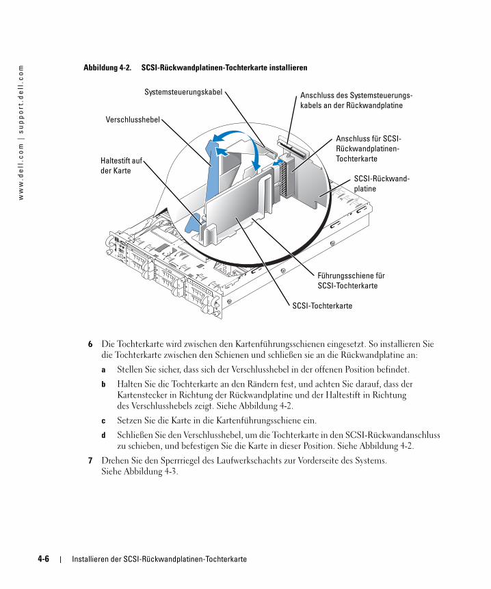
Abbildung 4-2. SCSI-Rückwandplatinen-Tochterkarte installieren6 Die Tochterkarte wird zwischen den Kartenführungsschienen eingesetzt. So installieren Sie die Tochterkarte zwischen den Schienen und schließen sie an die Rückwandplatine an:
a Stellen Sie sicher, dass sich der Verschlusshebel in der offenen Position befindet.
b Halten Sie die Tochterkarte an den Rändern fest, und achten Sie darauf, dass der Kartenstecker in Richtung der Rückwandplatine und der Haltestift in Richtung des Verschlusshebels zeigt. Siehe Abbildung 4-2.
c Setzen Sie die Karte in die Kartenführungsschiene ein.
d Schließen Sie den Verschlusshebel, um die Tochterkarte in den SCSI-Rückwandanschluss zu schieben, und befestigen Sie die Karte in dieser Position. Siehe Abbildung 4-2.
7 Drehen Sie den Sperrriegel des Laufwerkschachts zur Vorderseite des Systems. Siehe Abbildung 4-3.
SCSI-Tochterkarte
SCSI-Rückwand-
platine
Verschlusshebel
Führungsschiene für
SCSI-Tochterkarte
Haltestift auf
der Karte
Systemsteuerungskabel
Anschluss für SCSI-
Rückwandplatinen-
Tochterkarte
Anschluss des Systemsteuerungs-
kabels an der Rückwandplatine
4-6 Installieren der SCSI-Rückwandplatinen-Tochterkarte
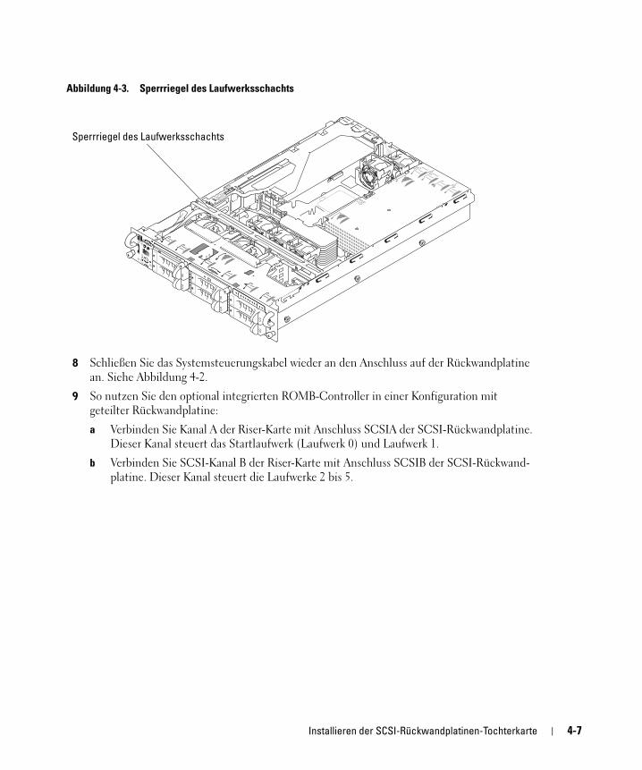
Abbildung 4-3. Sperrriegel des Laufwerksschachts
8 Schließen Sie das Systemsteuerungskabel wieder an den Anschluss auf der Rückwandplatine an. Siehe Abbildung 4-2.
9 So nutzen Sie den optional integrierten ROMB-Controller in einer Konfiguration mit geteilter Rückwandplatine:
a Verbinden Sie Kanal A der Riser-Karte mit Anschluss SCSIA der SCSI-Rückwandplatine. Dieser Kanal steuert das Startlaufwerk (Laufwerk 0) und Laufwerk 1.
b Verbinden Sie SCSI-Kanal B der Riser-Karte mit Anschluss SCSIB der SCSI-Rückwand-platine. Dieser Kanal steuert die Laufwerke 2 bis 5.
Sperrriegel des Laufwerksschachts
Installieren der SCSI-Rückwandplatinen-Tochterkarte 4-7
ww
w.d
ell
.co
m |
su
pp
or
t.d
ell
.co
m
So nutzen Sie die optionale RAID-Controllerkarte Konfiguration mit geteilter Rückwandplatine:a Verbinden Sie SCSI-Kanal A (Kanal 0) auf der Controllerkarte mit Anschluss SCSIA auf der SCSI-Rückwandplatine. Dieser Kanal steuert das Startlaufwerk (Laufwerk 0) und Laufwerk 1.
b Verbinden Sie SCSI-Kanal B (Kanal 1) auf der Controllerkarte mit Anschluss SCSIB auf der SCSI-Rückwandplatine. Dieser Kanal steuert die Laufwerke 2 bis 5.
ANMERKUNG: Wenn ein Kabel an den Anschluss SCSIB auf der SCSI-Rückwandplatine
angeschlossen ist, muss die SCSI-Rückwandplatinen-Tochterkarte im System installiert sein, damit
die Konfiguration mit 2/4-geteilter Rückwandplatine aktiviert werden kann. Andernfalls wird eine
Fehlermeldung angezeigt.
10 Drehen Sie den Sperrriegel des Laufwerkschachts zur Rückseite des Systems.
11 Schließen Sie das System.
12 Rufen Sie das System-Setup auf, um sich zu vergewissern, dass die RAID- bzw. SCSI-Controllerkarte korrekt konfiguriert wurde. Weitere Informationen hierzu finden Sie im Benutzerhandbuch Ihres Systems.
13 Bringen Sie gegebenenfalls die Blende wieder an.
4-8 Installieren der SCSI-Rückwandplatinen-Tochterkarte
Dell™ システム
SCSI バックプレーンドータ
カードの取り付け
w w w . d e l l . c o m | s u p p o r t . d e l l . c o m
メモ、注意、警告 メモ: メモは、コンピュータを使いやすくするための重要な情報を説明しています。
注意: 注意は、ハードウェアの損傷やデータの損失の可能性があることを示し、
その危険を回避するための方法を説明しています。
警告: 物的損害、けがまたは死亡の原因となる可能性があることを示します。
____________________
ここに記載されている内容は予告なく変更されることがあります。© 2004 すべての著作権は Dell Inc. にあります。
Dell Inc. の書面による許可のない複製は、いかなる形態においても厳重に禁じられています。
本書で使用されている商標について:Dell、DELL ロゴ、および PowerEdge は Dell Inc. の商標です。
本書では、必要に応じて上記以外の商標および会社名が使用されている場合がありますが、これらの商標や会社名は、一切 Dell Inc. に所属するものではありません。
2004 年 7 月 P/N F6589 Rev. A00
本書では、Dell™ PowerEdge™ 2800 または 2850 システムにバックプレーンドータカードを取り付けて、スプリット SCSI バックプレーンを構成する方法を説明します。スプリットバックプレーン構成では、ハードドライブが 2 つのドライブグループに分けて配列されます。
警告: システムのカバーを取り外して、システム内部に手を触れる作業は、トレーニングを
受けたサービス技術者の方だけが行ってください。安全上の注意、コンピュータ内部の作業、
および静電気障害への対処の詳細については、『製品情報ガイド』を参照してください。
メモ: コンポーネントの取り外しや交換の詳しい手順については、『インストール & トラブ
ルシューティングガイド』を参照してください。
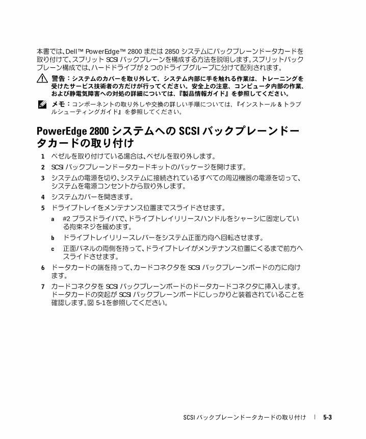
PowerEdge 2800 システムへの SCSI バックプレーンドータカードの取り付け1 ベゼルを取り付けている場合は、ベゼルを取り外します。
2 SCSI バックプレーンドータカードキットのパッケージを開けます。
3 システムの電源を切り、システムに接続されているすべての周辺機器の電源を切って、
システムを電源コンセントから取り外します。
4 システムカバーを開きます。
5 ドライブトレイをメンテナンス位置までスライドさせます。
a #2 プラスドライバで、ドライブトレイリリースハンドルをシャーシに固定している拘束ネジを緩めます。
b ドライブトレイリリースレバーをシステム正面方向へ回転させます。
c 正面パネルの両側を持って、ドライブトレイがメンテナンス位置にくるまで前方へ
スライドさせます。
6 ドータカードの端を持って、カードコネクタを SCSI バックプレーンボードの方に向けます。
7 カードコネクタを SCSI バックプレーンボードのドータカードコネクタに挿入します。ドータカードの突起が SCSI バックプレーンボードにしっかりと装着されていることを確認します。図 5-1を参照してください。
SCSI バックプレーンドータカードの取り付け 5-3
ww
w.d
ell
.co
m |
su
pp
or
t.d
ell
.co
m
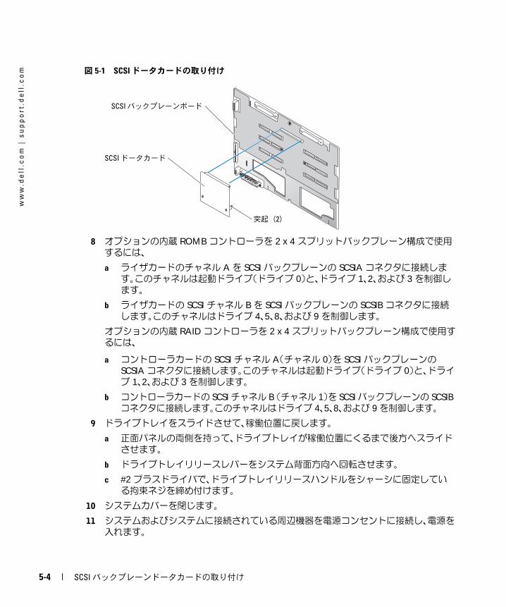
図 5-1 SCSI ドータカードの取り付け8 オプションの内蔵 ROMB コントローラを 2 x 4 スプリットバックプレーン構成で使用するには、
a ライザカードのチャネル A を SCSI バックプレーンの SCSIA コネクタに接続します。このチャネルは起動ドライブ(ドライブ 0)と、ドライブ 1、2、および 3 を制御します。
b ライザカードの SCSI チャネル B を SCSI バックプレーンの SCSIB コネクタに接続します。このチャネルはドライブ 4、5、8、および 9 を制御します。
オプションの内蔵 RAID コントローラを 2 x 4 スプリットバックプレーン構成で使用するには、
a コントローラカードの SCSI チャネル A(チャネル 0)を SCSI バックプレーンの SCSIA コネクタに接続します。このチャネルは起動ドライブ(ドライブ 0)と、ドライブ 1、2、および 3 を制御します。
b コントローラカードの SCSI チャネル B (チャネル 1)を SCSI バックプレーンの SCSIB コネクタに接続します。このチャネルはドライブ 4、5、8、および 9 を制御します。
9 ドライブトレイをスライドさせて、稼働位置に戻します。
a 正面パネルの両側を持って、ドライブトレイが稼働位置にくるまで後方へスライド
させます。
b ドライブトレイリリースレバーをシステム背面方向へ回転させます。
c #2 プラスドライバで、ドライブトレイリリースハンドルをシャーシに固定している拘束ネジを締め付けます。
10 システムカバーを閉じます。
11 システムおよびシステムに接続されている周辺機器を電源コンセントに接続し、電源を
入れます。
SCSI ドータカード
SCSI バックプレーンボード
突起(2)
5-4 SCSI バックプレーンドータカードの取り付け
12 セットアップユーティリティを起動し、RAID または SCSI コントローラカードが正しく設定されているか確認します。詳細については、お使いのシステムの『ユーザーズガイ
ド』を参照してください。
13 ベゼルを使用する場合は、ベゼルを取り付けます。
PowerEdge 2850 システムへの SCSI バックプレーンドータカードの取り付け1 SCSI バックプレーンボードのドータカードキットを開梱します。
2 システムの電源を切り、システムに接続されているすべての周辺機器の電源を切って、
システムを電源コンセントから取り外します。
3 ベゼルを取り付けている場合は、ベゼルを取り外します。
4 システムカバーを開きます。
5 システム背面側のコントロールパネルケーブルのプラスチック製タブを持って、ケーブ
ルコネクタをバックプレーンコネクタから抜き取ります。図 5-2を参照してください。
メモ: コントロールパネルケーブルのハーネスを持って引っ張ると、ハーネス破損の原
因となります。
SCSI バックプレーンドータカードコネクタとカードガイドは、コントロールパネルケーブルの下のコンパートメントに実装されています。
SCSI バックプレーンドータカードの取り付け 5-5
ww
w.d
ell
.co
m |
su
pp
or
t.d
ell
.co
m
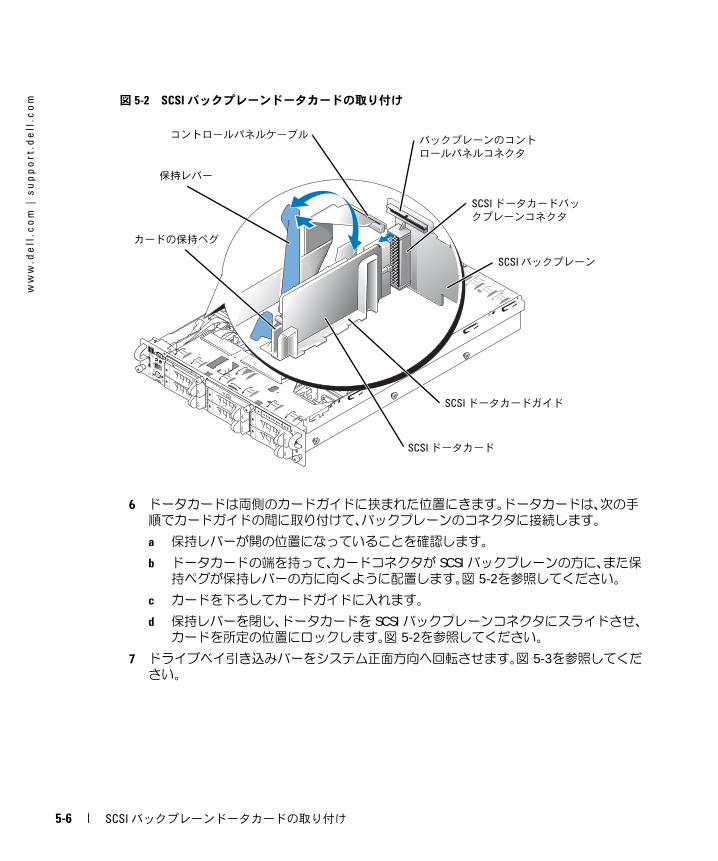
図 5-2 SCSIバックプレーンドータカードの取り付け6 ドータカードは両側のカードガイドに挟まれた位置にきます。ドータカードは、次の手
順でカードガイドの間に取り付けて、バックプレーンのコネクタに接続します。
a 保持レバーが開の位置になっていることを確認します。
b ドータカードの端を持って、カードコネクタが SCSI バックプレーンの方に、また保持ペグが保持レバーの方に向くように配置します。図 5-2を参照してください。
c カードを下ろしてカードガイドに入れます。
d 保持レバーを閉じ、ドータカードを SCSI バックプレーンコネクタにスライドさせ、カードを所定の位置にロックします。図 5-2を参照してください。
7 ドライブベイ引き込みバーをシステム正面方向へ回転させます。図 5-3を参照してください。
SCSI ドータカード
SCSI バックプレーン
保持レバー
SCSI ドータカードガイド
カードの保持ペグ
コントロールパネルケーブル
SCSI ドータカードバッ
クプレーンコネクタ
バックプレーンのコント
ロールパネルコネクタ
5-6 SCSI バックプレーンドータカードの取り付け
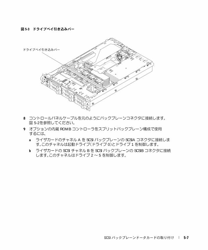
図 5-3 ドライブベイ引き込みバー
8 コントロールパネルケーブルを元のようにバックプレーンコネクタに接続します。
図 5-2を参照してください。
9 オプションの内蔵 ROMB コントローラをスプリットバックプレーン構成で使用するには、
a ライザカードのチャネル A を SCSI バックプレーンの SCSIA コネクタに接続します。このチャネルは起動ドライブ(ドライブ 0)とドライブ 1 を制御します。
b ライザカードの SCSI チャネル B を SCSI バックプレーンの SCSIB コネクタに接続します。このチャネルはドライブ 2 ~ 5 を制御します。
ドライブベイ引き込みバー
SCSI バックプレーンドータカードの取り付け 5-7
ww
w.d
ell
.co
m |
su
pp
or
t.d
ell
.co
m
オプションの RAID コントローラをスプリットバックプレーン構成で使用するには、a コントローラカードの SCSI チャネル A(チャネル 0)を SCSI バックプレーンの SCSIA コネクタに接続します。このチャネルは起動ドライブ(ドライブ 0)とドライブ 1 を制御します。
b コントローラカードの SCSI チャネル B(チャネル 1)を SCSI バックプレーンの SCSIB コネクタに接続します。このチャネルはドライブ 2 ~ 5 を制御します。
メモ: ケーブルが SCSIB バックプレーンコネクタに接続されている場合、SCSI バック
プレーンドータカードを取り付けて、2/4 スプリットバックプレーン構成を有効にする
必要があります。このようにしないと、エラーメッセージが表示されます。
10 ドライブベイ引き込みバーをシステム背面方向へ回転させます。
11 システムカバーを閉じます。
12 セットアップユーティリティを起動し、RAID または SCSI コントローラカードが正しく設定されているか確認します。詳細については、お使いのシステムの『ユーザーズガイ
ド』を参照してください。
13 ベゼルを使用する場合は、ベゼルを取り付けます。
5-8 SCSI バックプレーンドータカードの取り付け
Dell™ 시스템
SCSI 후면판 보조 카드 설치
w w w . d e l l . c o m | s u p p o r t . d e l l . c o m
주 , 주의사항 및 주의 참고: 주는 컴퓨터를 보다 효율적으로 사용할 수 있는 중요 정보를 제공합니다.
주의사항: 주의사항은 하드웨어의 손상 또는 데이터 유실 위험을 설명하며, 이러한 문제를 방지할 수 있는 방
법을 알려줍니다.
주의: 주의는 위험한 상황, 심각한 부상 또는 사망할 우려가 있음을 알려줍니다.
____________________
본 설명서에 수록된 정보는 사전 통보 없이 변경될 수 있습니다.© 2004 Dell Inc. All rights reserved.
Dell Inc.의 사전 승인 없이 어떠한 경우에도 무단 복제하는 것을 엄격히 금합니다.
본 설명서에 사용된 상표: Dell, DELL 로고 및 PowerEdge는 Dell Inc.의 상표입니다.
본 설명서에서 특정 회사의 표시나 제품 이름을 지칭하기 위해 기타 상표나 상호를 사용할 수도 있습니다. Dell Inc.은 자사가 소유하고 있는 것 이외에 기타 모든 등록 상표 및 상표 이름에 대한 어떠한 소유권도 없습니다.
2004 년 7 월 P/N F6589 Rev. A00
이 설명서에서는 후면판 보조 카드를 설치하여 Dell™ PowerEdge™ 2800 또는 2850 시스템에 분할 SCSI 후면판을 구성하는 방법을 설명합니다. 분할 후면판 구성에서 하드 드라이브는 두 개의 별도 드라이브 그룹으로 정렬됩니다.
주의 : 숙련된 서비스 기술자만 시스템 덮개를 분리하고 시스템 내부의 구성요소에 액세스해야
합니다 . 안전 지침 , 컴퓨터 내부 작업 및 정전기 방전 보호에 대한 자세한 내용은 시스템 정보 설
명서를 참조하십시오 .
참고: 구성 요소 제거 및 교체에 대한 세부 지침은 설치 및 문제 해결 설명서 를 참조하십시오.
PowerEdge 2800 시스템에 SCSI 후면판 보조 카드 설치1 배젤이 있는 경우, 이를 분리하십시오.
2 SCSI 후면판 보드 보조 카드 키트의 포장을 벗기십시오.
3 시스템과 시스템에 연결된 모든 주변장치의 전원을 끄고 전원 콘센트에서 시스템을 분리하십시오.
4 시스템을 여십시오.
5 드라이브 트레이를 유지보수 위치로 미십시오.
a #2 Phillips 드라이버를 사용하여 드라이브 트레이 분리 핸들을 섀시에 고정하는 나사를 푸십시오.
b 드라이브 트레이 분리 레버를 시스템 전면을 향해 돌리십시오.
c 전면 패널의 양 쪽을 잡고 드라이브 트레이가 유지보수 위치가 될 때까지 정면을 향해 드라이브 트레이를 미십시오.
6 카드 커넥터로 보조 카드의 가장자리를 잡고 SCSI 후면판 보드를 향하도록 하십시오.
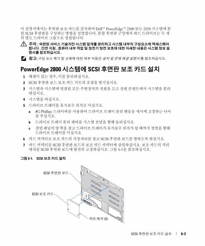
7 카드 커넥터를 SCSI 후면판 보드의 보조 카드 커넥터에 삽입하십시오. 보조 카드의 격리 애자를 SCSI 후면판 보드에 완전히 고정하십시오. 그림 6-1을 참조하십시오.
그림 6-1. SCSI 보조 카드 설치
SCSI 보조 카드
SCSI 후면판 보드
격리 애자 (2)
SCSI 후면판 보조 카드 설치 6-3
ww
w.d
ell
.co
m |
su
pp
or
t.d
ell
.co
m
8 선택 사양인 내장형 ROMB 컨트롤러를 분할 2 x 4 후면판 구성에서 사용하려면:a 라이저 카드의 채널 A를 SCSI 후면판의 SCSIA에 연결하십시오. 이 채널은 부팅 드라이브(드라이브 0) 및 드라이브 1, 2, 3을 제어합니다.
b 라이저 카드의 SCSI 채널 B를 SCSI 후면판의 커넥터 SCSIB에 연결하십시오. 이 채널은 드라이브 4, 5, 8 및 9를 제어합니다.
선택 사양인 RAID 컨트롤러를 분할 2 x 4 후면판 구성에서 사용하려면:
a 컨트롤러 카드의 SCSI 채널 A(채널 0)를 SCSI 후면판의 커넥터 SCSIA에 연결하십시오. 이 채널은 부팅 드라이브(드라이브 0) 및 드라이브 1, 2, 3을 제어합니다.
b 컨트롤러 카드의 SCSI 채널 B(채널 1)를 SCSI 후면판의 커넥터 SCSIB에 연결하십시오. 이 채널은 드라이브 4, 5, 8 및 9를 제어합니다.
9 드라이브 트레이를 작동 위치로 다시 미십시오.
a 전면 패널의 양 쪽을 잡고 드라이브 트레이가 작동 위치가 될 때까지 후면을 향해 드라이브 트레이를 미십시오.
b 드라이브 트레이 분리 레버를 시스템 후면을 향해 돌리십시오.
c #2 Phillips 드라이버를 사용하여 드라이브 트레이 분리 핸들을 섀시에 고정하는 나사를 조이십시오.
10 시스템을 닫으십시오.
11 시스템을 전원 콘센트에 다시 연결하고 시스템과 시스템에 연결된 주변장치의 전원을 모두 켜십시오.
12 시스템 설치 프로그램을 실행하여 RAID 또는 SCSI 컨트롤러 카드가 제대로 구성되었는지 확인하십시오. 자세한 내용은 시스템 사용 설명서를 참조하십시오.
13 배젤이 있는 경우, 교체하십시오.
PowerEdge 2850 시스템에 SCSI 후면판 보조 카드 설치1 SCSI 후면판 보드 보조 카드 키트의 포장을 벗기십시오.
2 시스템과 시스템에 연결된 모든 주변장치의 전원을 끄고 전원 콘센트에서 시스템을 분리하십시오.
3 배젤이 있는 경우, 이를 분리하십시오.
4 시스템을 여십시오.
5 제어판 케이블의 뒷면에 있는 플라스틱 탭을 잡고 케이블 커넥터를 후면판 커넥터에서 잡아당기십시오. 그림 6-2을 참조하십시오.
참고 : 제어판 케이블 연결을 잡아 당기면 연결이 손상될 수 있습니다 .
SCSI 후면판 보조 카드 커넥터와 카드 가이드는 제어판 케이블 아래 있는 칸막이에 있습니다.
6-4 SCSI 후면판 보조 카드 설치
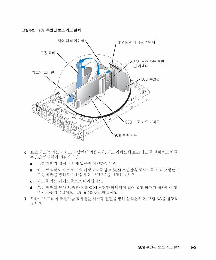
그림 6-2. SCSI 후면판 보조 카드 설치
6 보조 카드는 카드 가이드의 양면에 끼웁니다. 카드 가이드에 보조 카드를 설치하고 이를 후면판 커넥터에 연결하려면:
a 고정 레버가 열림 위치에 있는지 확인하십시오.
b 카드 커넥터로 보조 카드의 가장자리를 잡고 SCSI 후면판을 향하도록 하고 고정판이 고정 레버를 향하도록 하십시오. 그림 6-2을 참조하십시오.
c 카드를 카드 가이드쪽으로 내리십시오.
d 고정 레버를 닫아 보조 카드를 SCSI 후면판 커넥터에 밀어 넣고 카드가 제자리에 고정되도록 잠그십시오. 그림 6-2을 참조하십시오.
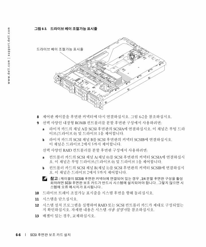
7 드라이브 트레이 조절가능 표시줄을 시스템 전면을 향해 돌리십시오. 그림 6-3을 참조하십시오.
SCSI 보조 카드
SCSI 후면판
고정 레버
SCSI 보조 카드 가이드
카드의 고정판
제어 패널 케이블
SCSI 보조 카드 후면
판 커넥터
후면판의 제어판 커넥터
SCSI 후면판 보조 카드 설치 6-5
ww
w.d
ell
.co
m |
su
pp
or
t.d
ell
.co
m
그림 6-3. 드라이브 베이 조절가능 표시줄8 제어판 케이블을 후면판 커넥터에 다시 연결하십시오. 그림 6-2을 참조하십시오.
9 선택 사양인 내장형 ROMB 컨트롤러를 분할 후면판 구성에서 사용하려면:
a 라이저 카드의 채널 A를 SCSI 후면판의 SCSIA에 연결하십시오. 이 채널은 부팅 드라이브(드라이브 0) 및 드라이브 1을 제어합니다.
b 라이저 카드의 SCSI 채널 B를 SCSI 후면판의 커넥터 SCSIB에 연결하십시오. 이 채널은 드라이브 2에서 5까지 제어합니다.
선택 사양인 RAID 컨트롤러를 분할 후면판 구성에서 사용하려면:
a 컨트롤러 카드의 SCSI 채널 A(채널 0)를 SCSI 후면판의 커넥터 SCSIA에 연결하십시오. 이 채널은 부팅 드라이브(드라이브 0) 및 드라이브 1을 제어합니다.
b 컨트롤러 카드의 SCSI 채널 B(채널 1)를 SCSI 후면판의 커넥터 SCSIB에 연결하십시오. 이 채널은 드라이브 2에서 5까지 제어합니다.
참고 : 케이블이 SCSIB 후면판 커넥터에 연결되어 있는 경우 , 2/4 분할 후면판 구성을 활성
화하려면 SCSI 후면판 보조 카드가 반드시 시스템에 설치되어야 합니다 . 그렇지 않으면 시
스템에 오류 메시지가 표시됩니다 .
10 드라이브 트레이 조절가능 표시줄을 시스템 후면을 향해 돌리십시오.
11 시스템을 닫으십시오.
12 시스템 설치 프로그램을 실행하여 RAID 또는 SCSI 컨트롤러 카드가 제대로 구성되었는지 확인하십시오. 자세한 내용은 시스템 사용 설명서를 참조하십시오.
13 배젤이 있는 경우, 교체하십시오.
드라이브 베이 조절가능 표시줄
6-6 SCSI 후면판 보조 카드 설치
Sistemas Dell™
Instalación de la tarjeta
secundaria de plano
posterior SCSI
w w w . d e l l . c o m | s u p p o r t . d e l l . c o m
Notas, avisos y precauciones
NOTA: una NOTA proporciona información importante que le ayudará a utilizar mejor el ordenador.
AVISO: un AVISO indica un posible daño en el hardware o la pérdida de datos, e informa de cómo evitar el problema.
PRECAUCIÓN: un mensaje de PRECAUCIÓN indica el riesgo de daños materiales, lesiones corporales o incluso la muerte.
____________________
La información contenida en este documento puede modificarse sin previo aviso.© 2004 Dell Inc. Reservados todos los derechos.
Queda estrictamente prohibida la reproducción de este documento en cualquier forma sin la autorización por escrito de Dell Inc.
Marcas comerciales que aparecen en el texto: Dell, el logotipo de DELL y PowerEdge son marcas comerciales de Dell Inc.
Otras marcas y otros nombres comerciales pueden utilizarse en este documento para hacer referencia a las entidades que los poseen o a sus productos. Dell Inc. renuncia a cualquier interés en la titularidad de derechos sobre marcas comerciales y nombres comerciales que no sean los suyos.
Julio de 2004 P/N F6589 Rev. A00
En este documento se proporciona información sobre cómo configurar el plano posterior SCSI dividido del sistema Dell™ PowerEdge™ 2800 o 2850 instalando una tarjeta secundaria de plano posterior. En una configuración de plano posterior dividido, las unidades de disco duro están dispuestas en dos grupos de unidades.
PRECAUCIÓN: los técnicos de servicio especializados son las únicas personas autorizadas para retirar las cubiertas y acceder a los componentes internos del sistema. Consulte la Guía de
información del producto para obtener información completa sobre las precauciones de seguridad, la manipulación de las piezas internas del ordenador y la protección contra descargas electrostáticas.
NOTA: consulte la Guía de instalación y solución de problemas para obtener instrucciones detalladas
sobre la extracción y la colocación de componentes.
Instalación de la tarjeta secundaria de plano posterior SCSI en un sistema PowerEdge 28001 Retire el bisel (si procede).
2 Desembale el kit de la tarjeta secundaria de plano posterior SCSI.
3 Apague el sistema, incluidos todos los periféricos conectados, y desconéctelo de la toma eléctrica.
4 Abra el sistema.
5 Extraiga la bandeja de la unidad hasta la posición de mantenimiento.
a Con un destornillador Phillips del nº 2, afloje el tornillo cautivo que fija la manija de liberación de la bandeja del sistema al chasis.
b Gire la palanca de liberación de la bandeja del sistema hacia la parte frontal del sistema.
c Sujete ambos lados del panel frontal y deslice la bandeja de la unidad hacia delante hasta que esté en la posición de mantenimiento.
6 Sostenga la tarjeta secundaria por los bordes con el conector de la tarjeta orientado hacia la tarjeta de plano posterior SCSI.
7 Inserte el conector de la tarjeta en el conector de la tarjeta secundaria de la tarjeta de plano posterior SCSI. Asegúrese de que los separadores de la tarjeta secundaria estén encajados correctamente en la tarjeta de plano posterior SCSI. Consulte la figura 7-1.
Instalación de la tarjeta secundaria de plano posterior SCSI 7-3

ww
w.d
ell
.co
m |
su
pp
or
t.d
ell
.co
m
Figura 7-1. Instalación de una tarjeta secundaria SCSI8 Para utilizar la controladora ROMB integrada opcional en una configuración de plano posterior dividido 2 x 4:
a Conecte el canal A de la tarjeta vertical al conector SCSIA del plano posterior SCSI. Este canal controla la unidad de arranque (unidad 0) y las unidades 1, 2 y 3.
b Conecte el canal B SCSI de la tarjeta vertical al conector SCSIB del plano posterior SCSI. Este canal controla las unidades 4, 5, 8 y 9.
Para utilizar una tarjeta controladora RAID opcional en una configuración de plano posterior dividido 2 x 4:
a Conecte el canal A (canal 0) SCSI de la tarjeta controladora al conector SCSIA del plano posterior SCSI. Este canal controla la unidad de arranque (unidad 0) y las unidades 1, 2 y 3.
b Conecte el canal B (canal 1) SCSI de la tarjeta controladora al conector SCSIB del plano posterior SCSI. Este canal controla las unidades 4, 5, 8 y 9.
9 Deslice la bandeja de la unidad hasta la posición de funcionamiento.
a Sujete ambos lados del panel frontal y deslice la bandeja de la unidad hacia atrás hasta la posición de funcionamiento.
b Gire la palanca de liberación de la bandeja de la unidad hacia la parte posterior del sistema.
c Con un destornillador Phillips del nº 2, apriete el tornillo cautivo que fija la manija de liberación de la bandeja de la unidad al chasis.
10 Cierre el sistema.
11 Vuelva a conectar el sistema a la toma eléctrica y enciéndalo, incluidos todos los periféricos conectados.
12 Abra el programa de configuración del sistema para asegurarse de que la tarjeta controladora RAID o SCSI esté configurada correctamente. Para obtener más información, consulte la Guía del usuario del sistema.
13 Vuelva a colocar el bisel (si procede).
Tarjeta secundaria SCSI
Tarjeta de plano posterior SCSI
Separadores (2)
7-4 Instalación de la tarjeta secundaria de plano posterior SCSI
Instalación de la tarjeta secundaria de plano posterior SCSI en un sistema PowerEdge 28501 Desembale el kit de la tarjeta secundaria de plano posterior SCSI.
2 Apague el sistema, incluidos todos los periféricos conectados, y desconéctelo de la toma eléctrica.
3 Retire el bisel (si procede).
4 Abra el sistema.
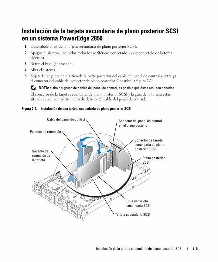
5 Sujete la lengüeta de plástico de la parte posterior del cable del panel de control y extraiga el conector del cable del conector de plano posterior. Consulte la figura 7-2.
NOTA: si tira del grupo de cables del panel de control, es posible que éstos resulten dañados.
El conector de la tarjeta secundaria de plano posterior SCSI y la guía de la tarjeta están situados en el compartimiento de debajo del cable del panel de control.
Figura 7-2. Instalación de una tarjeta secundaria de plano posterior SCSI
Tarjeta secundaria SCSI
Plano posterior
SCSI
Palanca de retención
Guía de tarjeta
secundaria SCSI
Saliente de
retención de
la tarjeta
Cable del panel de control
Conector de tarjeta
secundaria de plano
posterior SCSI
Conector del panel de control
en el plano posterior
Instalación de la tarjeta secundaria de plano posterior SCSI 7-5
ww
w.d
ell
.co
m |
su
pp
or
t.d
ell
.co
m
6 La tarjeta secundaria encaja entre los dos lados de la guía de la tarjeta. Para instalar la tarjeta secundaria en la guía de la tarjeta y conectarla al conector de plano posterior:a Asegúrese de que la palanca de retención esté en la posición abierta.
b Sostenga la tarjeta secundaria por los bordes con el conector de la tarjeta orientado hacia el plano posterior SCSI y el saliente de retención orientado hacia la palanca de retención. Consulte la figura 7-2.
c Introduzca la tarjeta en la guía.
d Cierre la palanca de retención para insertar y fijar la tarjeta secundaria en el conector de plano posterior SCSI. Consulte la figura 7-2.
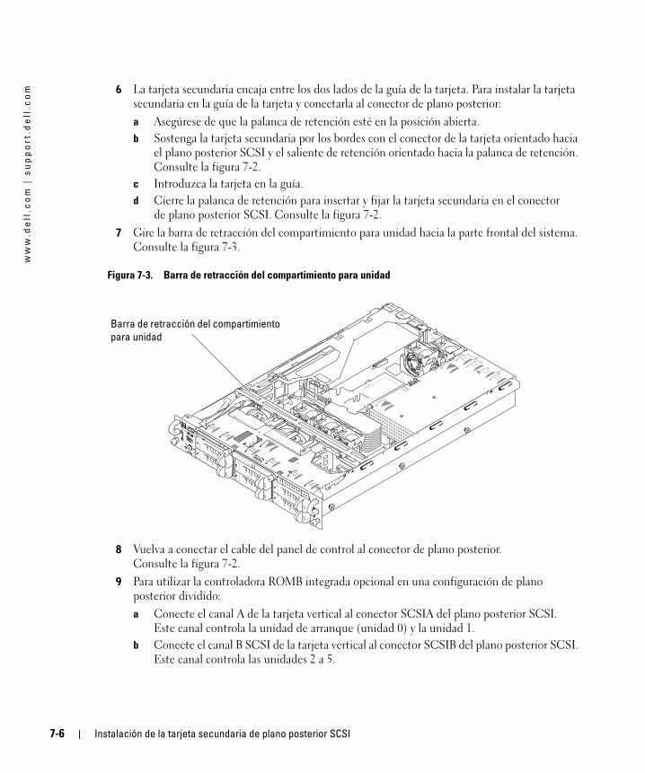
7 Gire la barra de retracción del compartimiento para unidad hacia la parte frontal del sistema. Consulte la figura 7-3.
Figura 7-3. Barra de retracción del compartimiento para unidad
8 Vuelva a conectar el cable del panel de control al conector de plano posterior. Consulte la figura 7-2.
9 Para utilizar la controladora ROMB integrada opcional en una configuración de plano posterior dividido:
a Conecte el canal A de la tarjeta vertical al conector SCSIA del plano posterior SCSI. Este canal controla la unidad de arranque (unidad 0) y la unidad 1.
b Conecte el canal B SCSI de la tarjeta vertical al conector SCSIB del plano posterior SCSI. Este canal controla las unidades 2 a 5.
Barra de retracción del compartimiento
para unidad
7-6 Instalación de la tarjeta secundaria de plano posterior SCSI
Para utilizar la tarjeta controladora RAID opcional en una configuración de plano posterior dividido:
a Conecte el canal A (canal 0) SCSI de la tarjeta controladora al conector SCSIA del plano posterior SCSI. Este canal controla la unidad de arranque (unidad 0) y la unidad 1.
b Conecte el canal B (canal 1) SCSI de la tarjeta controladora al conector SCSIB del plano posterior SCSI. Este canal controla las unidades 2 a 5.
NOTA: si hay conectado un cable al conector del plano posterior SCSIB, deberá instalar la tarjeta
secundaria de plano posterior SCSI para activar la configuración de plano posterior dividido 2/4.
De lo contrario, el sistema mostrará un mensaje de error.
10 Gire la barra de retracción del compartimiento para unidad hacia la parte posterior del sistema.
11 Cierre el sistema.
12 Abra el programa de configuración del sistema para asegurarse de que la tarjeta controladora RAID o SCSI esté configurada correctamente. Para obtener más información, consulte la Guía del usuario del sistema.
13 Vuelva a colocar el bisel (si procede).
Instalación de la tarjeta secundaria de plano posterior SCSI 7-7
ww
w.d
ell
.co
m |
su
pp
or
t.d
ell
.co
m
7-8 Instalación de la tarjeta secundaria de plano posterior SCSI
![Microsoft Zertifizierung Exam 70-410 Installing and ...pebo2000.de/data/documents/DEMO-Microsoft-70-410-deutsch.pdf · Installing and Configuring Windows Server 2012 [479 Fragen/Antworten]](https://img.pdfslide.org/doc/110x75/5a7891db7f8b9aa2448de505/microsoft-zertifizierung-exam-70-410-installing-and-and-configuring-windows.jpg)