Embed Size (px)
Citation preview
Starter-Set
78302DGB F
Instruction ManualBedienungsanleitungNotice d’utilisationGebruiksaanwijzingInstrucciones de empleoIstruzioni di impiego
NL
2
D1. Sicherheitshinweise 72. Anschluss des Fahrpultes und Aufbau der Gleise 73. Kurzschluss oder Überlastung 104. Funktionsstörungen 105. Reinigung und Wartung 106. Entsorgung 107. Garantie 10
1. Safety Notes 32. Connections for the Locomotive Controller and the Track 33. Short Circuit or Overload 64. Trouble Running the Train 65. Cleaning and Maintenance 66. Disposing 67. Warranty 6
1. Remarques concernant la sécurité 112. Raccordement du pupitre de commande et de la voie 113. Court-circuit ou surcharge 144. Dysfonctionnements 145. Nettoyage et entretien 146. Elimination 147. Garantie 14
1. Veiligheidsaanwijzingen 152. Rijregelaar aansluiten en opbouw van de rails 153. Kortsluiting of overbelasting 184. Storingen 185. Reiniging en onderhoud 186. Afdanken 187. Garantie 18
1. Advertencias de seguridad 192. Conexión del pupitre de conducción y montaje de las vías 193. Cortocircuito o sobrecarga 224. Anomalías funcionales 225. Limpieza y mantenimiento 226. Eliminación 227. Garantía 22
1. Avvertenze di sicurezza 232. Collegamento del quadro di comando e montaggio dei binari 233. Corto circuito oppure sovraccarico 264. Difetti nel funzionamento 265. Pulizia e manutenzione 266. Smaltimento 267. Garanzia 26
1. Safety Notes 32. Connections for the Locomotive Controller and the Track 33. Short Circuit or Overload 64. Trouble Running the Train 65. Cleaning and Maintenance 66. Disposing 67. Warranty 6
1. Safety Notes 32. Connections for the Locomotive Controller and the Track 33. Short Circuit or Overload 64. Trouble Running the Train 65. Cleaning and Maintenance 66. Disposing 67. Warranty 6
GB2. Connections for the Locomotive Controller
GB2. Connections for the Locomotive Controller and the Track 3GB and the Track 33. Short Circuit or Overload 6GB3. Short Circuit or Overload 64. Trouble Running the Train 6GB4. Trouble Running the Train 65. Cleaning and Maintenance 6GB5. Cleaning and Maintenance 66. Disposing 6GB6. Disposing 6
1. Remarques concernant la sécurité 112. Raccordement du pupitre de commande et de la voie 113. Court-circuit ou surcharge 144. Dysfonctionnements 145. Nettoyage et entretien 146. Elimination 147. Garantie 14
1. Remarques concernant la sécurité 112. Raccordement du pupitre de commande et de la voie 113. Court-circuit ou surcharge 144. Dysfonctionnements 145. Nettoyage et entretien 146. Elimination 147. Garantie 14
F2. Raccordement du pupitre de commande et F2. Raccordement du pupitre de commande et de la voie 11F de la voie 113. Court-circuit ou surcharge 14F3. Court-circuit ou surcharge 144. Dysfonctionnements 14F4. Dysfonctionnements 145. Nettoyage et entretien 14F5. Nettoyage et entretien 14
1. Veiligheidsaanwijzingen 15Rijregelaar aansluiten en opbouw van de rails
3. Kortsluiting of overbelasting 184. Storingen 185. Reiniging en onderhoud 186. Afdanken 187. Garantie 18
1. Veiligheidsaanwijzingen 15Rijregelaar aansluiten en opbouw van de rails
3. Kortsluiting of overbelasting 184. Storingen 185. Reiniging en onderhoud 186. Afdanken 187. Garantie 18
NL Rijregelaar aansluiten en opbouw van de rails
NL Rijregelaar aansluiten en opbouw van de rails
3. Kortsluiting of overbelasting 18NL 3. Kortsluiting of overbelasting 184. Storingen 18NL 4. Storingen 185. Reiniging en onderhoud 18NL 5. Reiniging en onderhoud 186. Afdanken 18NL 6. Afdanken 18
Advertencias de seguridad 192. Conexión del pupitre de conducción y montaje de las vías 193. Cortocircuito o sobrecarga 224. Anomalías funcionales 225. Limpieza y mantenimiento 226. Eliminación 227. Garantía 22
Advertencias de seguridad 192. Conexión del pupitre de conducción y montaje de las vías 193. Cortocircuito o sobrecarga 224. Anomalías funcionales 225. Limpieza y mantenimiento 226. Eliminación 227. Garantía 22
2. Conexión del pupitre de conducción y montaje de las vías 193. Cortocircuito o sobrecarga 224. Anomalías funcionales 225. Limpieza y mantenimiento 226. Eliminación 22
1. Avvertenze di sicurezza 232. Collegamento del quadro di comando e montaggio dei binari 233. Corto circuito oppure sovraccarico 264. Difetti nel funzionamento 265. Pulizia e manutenzione 266. Smaltimento 267. Garanzia 26
1. Avvertenze di sicurezza 232. Collegamento del quadro di comando e montaggio dei binari 233. Corto circuito oppure sovraccarico 264. Difetti nel funzionamento 265. Pulizia e manutenzione 266. Smaltimento 267. Garanzia 26
2. Collegamento del quadro di comando e montaggio dei binari 233. Corto circuito oppure sovraccarico 264. Difetti nel funzionamento 265. Pulizia e manutenzione 266. Smaltimento 26
3
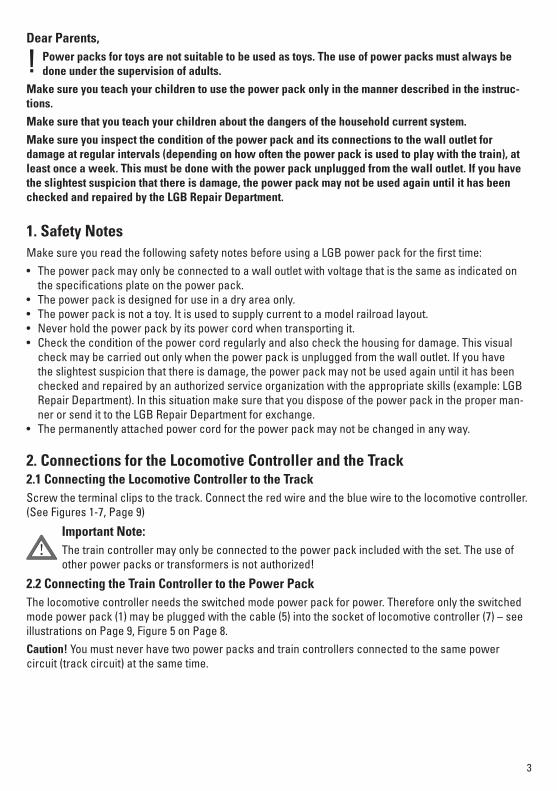
2. Connections for the Locomotive Controller and the Track2.1 Connecting the Locomotive Controller to the TrackScrew the terminal clips to the track. Connect the red wire and the blue wire to the locomotive controller. (See Figures 1-7, Page 9)
Important Note:The train controller may only be connected to the power pack included with the set. The use of other power packs or transformers is not authorized!
2.2 Connecting the Train Controller to the Power PackThe locomotive controller needs the switched mode power pack for power. Therefore only the switched mode power pack (1) may be plugged with the cable (5) into the socket of locomotive controller (7) – see illustrations on Page 9, Figure 5 on Page 8. Caution! You must never have two power packs and train controllers connected to the same power circuit (track circuit) at the same time.
1. Safety NotesMake sure you read the following safety notes before using a LGB power pack for the first time:• The power pack may only be connected to a wall outlet with voltage that is the same as indicated on
the specifications plate on the power pack. • The power pack is designed for use in a dry area only.• The power pack is not a toy. It is used to supply current to a model railroad layout.• Never hold the power pack by its power cord when transporting it.• Check the condition of the power cord regularly and also check the housing for damage. This visual
check may be carried out only when the power pack is unplugged from the wall outlet. If you have the slightest suspicion that there is damage, the power pack may not be used again until it has been checked and repaired by an authorized service organization with the appropriate skills (example: LGB Repair Department). In this situation make sure that you dispose of the power pack in the proper man-ner or send it to the LGB Repair Department for exchange.
• The permanently attached power cord for the power pack may not be changed in any way.
Dear Parents,Power packs for toys are not suitable to be used as toys. The use of power packs must always be done under the supervision of adults.
Make sure you teach your children to use the power pack only in the manner described in the instruc-tions.
Make sure that you teach your children about the dangers of the household current system.
Make sure you inspect the condition of the power pack and its connections to the wall outlet for damage at regular intervals (depending on how often the power pack is used to play with the train), at least once a week. This must be done with the power pack unplugged from the wall outlet. If you have the slightest suspicion that there is damage, the power pack may not be used again until it has been checked and repaired by the LGB Repair Department.
!
!
4
2.3 Connections for the Power PackThe power pack may not be plugged into the wall outlet until the wiring for the layout is finished.
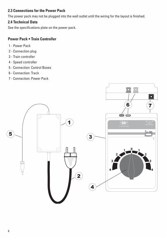
2.4 Technical Data See the specifications plate on the power pack.
Power Pack • Train Controller
1 - Power Pack 2 - Connection plug 3 - Train controller 4 - Speed controller 5 - Connection: Control Boxes 6 - Connection: Track 7 - Connection: Power Pack
2 10 - 20V DC max.
INPUTmax. 25V DC
5
1
2
3
4
6 7
5
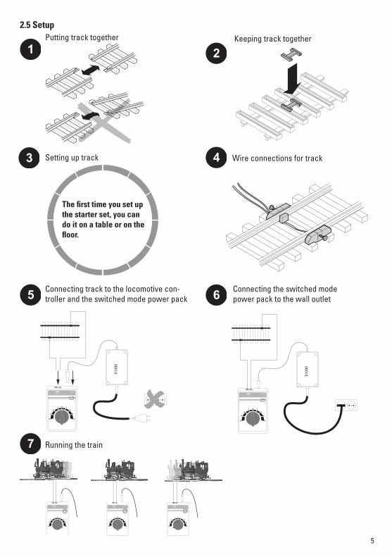
2.5 Setup
1 2
3 4
5 6
7
2 10 - 20V DC max.
INPUTmax. 25V DC
5109
0
2 10 - 20V DC max.
INPUTmax. 25V DC
5109
0
2 10 - 20V DC max.
INPUTmax. 25V DC
2 10 - 20V DC max.
INPUTmax. 25V DC2 1
0 - 20V DC max.
INPUTmax. 25V DC
The fi rst time you set up the starter set, you can do it on a table or on the fl oor.
Putting track together Keeping track together
Setting up track Wire connections for track
Connecting track to the locomotive con-troller and the switched mode power pack
Running the train
Connecting the switched mode power pack to the wall outlet
6
3. Short Circuit or OverloadOverload Protection
A built-in overload protection protects the power pack in the event of an overload or a short circuit. The locomotives will come to a stop, solenoid accessories cannot be controlled, and all lamps/lights con-nected to the layout will go out.The following procedure is recommended:
1. Unplug the power pack from the wall outlet.2. Look on the layout for the cause of the short circuit and correct it.3. After about 1 minute the overload protection will go back to regular operation. After this period of time
has passed, the power pack can be used again.If the power pack shuts off again without a short circuit being found, then the power pack is overloaded. In this situation the number of users on the layout (locomotives, solenoid accessories, and lamps/lights) must be reduced.
4. Trouble Running the Train• If the locomotive does not run, check to make sure that the connections (see setup) are correct or that
the wire insulation was pushed into the terminal or that the switched mode power pack is plugged into the power outlet.
• If the locomotive becomes damaged, do not use the locomotive anymore. If car becomes damaged, remove this car from the train and do not use it anymore.
5. Cleaning and Maintenance • Check to see if hair or dirt gets on the axles on the train and remove this hair or dirt from the axles with
the help of a pair or tweezers so that the train runs correctly.• Der Zug kann mit einem trockenen, fusselfreien Tuch oder einem weichen Pinsel gereinigt werden.• Additional information about servicing your locomotive can be found in the instructions for it.
6. DisposingProducts marked with a trash container with a line through it may not be disposed of at the end of their useful life in the normal household trash. They must be taken to a collection point for the recycling of electrical and electronic devices. There is a symbol on the product, the operating instructions, or the packaging to this effect. The materials in these items can be used again according to this marking. By reusing old devices, materially recycling, or recycling
in some other form of old devices such as these you make an important contribution to the protection of our environment. Please ask your city, town, community, or county authorities for the location of the appropriate disposal site.
7. WarrantyThe warranty card included with this product specifies the warranty conditions.• Please contact your authorized Märklin dealer for repairs or contact: Gebr. Märklin & Cie. GmbH Reparaturservice Stuttgarter Str. 55 - 57 73033 Göppingen Germany Tel: +49 7161 608 222 E-Mail: [email protected]
7
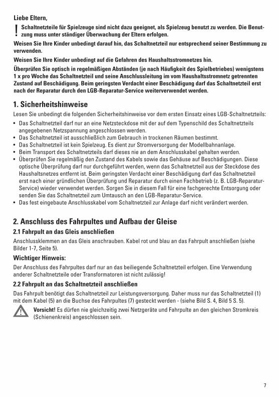
Liebe Eltern,Schaltnetzteile für Spielzeuge sind nicht dazu geeignet, als Spielzeug benutzt zu werden. Die Benut-zung muss unter ständiger Überwachung der Eltern erfolgen.
Weisen Sie Ihre Kinder unbedingt darauf hin, das Schaltnetzteil nur entsprechend seiner Bestimmung zu verwenden.
Weisen Sie Ihre Kinder unbedingt auf die Gefahren des Haushaltsstromnetzes hin.
Überprüfen Sie optisch in regelmäßigen Abständen (je nach Häufigkeit des Spielbetriebes) wenigstens 1 x pro Woche das Schaltnetzteil und seine Anschlussleitung im vom Haushaltsstromnetz getrennten Zustand auf Beschädigung. Beim geringsten Verdacht einer Beschädigung darf das Schaltnetzteil erst nach der Reparatur durch den LGB-Reparatur-Service weiterverwendet werden.
!
1. Sicherheitshinweise Lesen Sie unbedingt die folgenden Sicherheitshinweise vor dem ersten Einsatz eines LGB-Schaltnetzteils:• Das Schaltnetzteil darf nur an eine Netzsteckdose mit der auf dem Typenschild des Schaltnetzteils
angegebenen Netzspannung angeschlossen werden.• Das Schaltnetzteil ist ausschließlich zum Gebrauch in trockenen Räumen bestimmt.• Das Schaltnetzteil ist kein Spielzeug. Es dient zur Stromversorgung der Modellbahnanlage.• Beim Transport des Schaltnetzteils darf dieses nie an dem Anschlusskabel gehalten werden.• Überprüfen Sie regelmäßig den Zustand des Kabels sowie das Gehäuse auf Beschädigungen. Diese
optische Überprüfung darf nur durchgeführt werden, wenn das Schaltnetzteil aus der Steckdose des Haushaltsnetzes entfernt ist. Beim geringsten Verdacht einer Beschädigung darf das Schaltnetzteil erst nach einer gründlichen Überprüfung und Reparatur durch einen Fachbetrieb (z. B. LGB-Reparatur-Service) wieder verwendet werden. Sorgen Sie in diesem Fall für eine fachgerechte Entsorgung oder senden Sie das Schaltnetzteil zum Umtausch an den LGB-Reparatur-Service.
• Das fest eingebaute Anschlusskabel vom Schaltnetzteil zur Anlage darf nicht verändert werden.
2. Anschluss des Fahrpultes und Aufbau der Gleise2.1 Fahrpult an das Gleis anschließenAnschlussklemmen an das Gleis anschrauben. Kabel rot und blau an das Fahrpult anschließen (siehe Bilder 1-7, Seite 5).
Wichtiger Hinweis:Der Anschluss des Fahrpultes darf nur an das beiliegende Schaltnetzteil erfolgen. Eine Verwendung anderer Schaltnetzteile oder Transformatoren ist nicht zulässig!
2.2 Fahrpult an das Schaltnetzteil anschließenDas Fahrpult benötigt das Schaltnetzteil zur Leistungsversorgung. Daher muss nur das Schaltnetzteil (1) mit dem Kabel (5) an die Buchse des Fahrpultes (7) gesteckt werden - (siehe Bild S. 4, Bild 5 S. 5).
Vorsicht! Es dürfen nie gleichzeitig zwei Netzgeräte und Fahrpulte an den gleichen Stromkreis (Schienenkreis) angeschlossen sein.
!
8
2 10 - 20V DC max.
INPUTmax. 25V DC
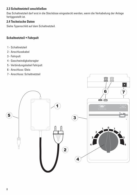
1 - Schaltnetzteil 2 - Anschlusskabel 3 - Fahrpult 4 - Geschwindigkeitsregler 5 - Verbindungskabel Fahrpult 6 - Anschluss: Gleis 7 - Anschluss: Schaltnetzteil
Schaltnetzteil • Fahrpult
5
1
2
3
4
6 7
2.3 Schaltnetzteil anschließenDas Schaltnetzteil darf erst in die Steckdose eingesteckt werden, wenn die Verkabelung der Anlage fertiggestellt ist.
2.4 Technische DatenSiehe Typenschild auf dem Schaltnetzteil.
9
12
3 4
5 6
7
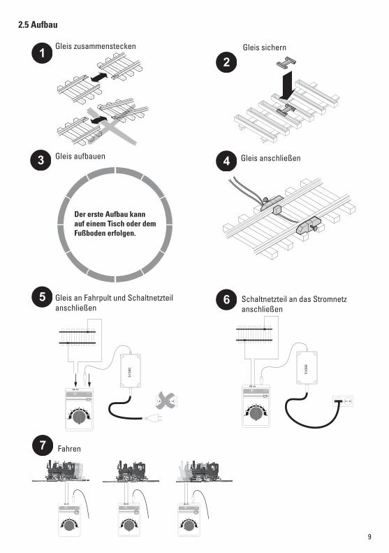
2.5 Aufbau
2 10 - 20V DC max.
INPUTmax. 25V DC
5109
0
2 1
0 - 20V DC max.
INPUTmax. 25V DC
5109
0
2 10 - 20V DC max.
INPUTmax. 25V DC
2 10 - 20V DC max.
INPUTmax. 25V DC2 1
0 - 20V DC max.
INPUTmax. 25V DC
Der erste Aufbau kann auf einem Tisch oder dem Fußboden erfolgen.
Gleis zusammenstecken Gleis sichern
Gleis aufbauen Gleis anschließen
Gleis an Fahrpult und Schaltnetzteil anschließen
Schaltnetzteil an das Stromnetz anschließen
Fahren
10
3. Kurzschluss oder Überlastung Überlastschutz
Ein eingebauter Überlastschutz schützt das Schaltnetzteil bei Überlastung oder Kurzschluss vor Be-schädigungen. Die Loks bleiben alle stehen, die Magnetartikel lassen sich nicht mehr schalten und alle angeschlossenen Lampen erlöschen.Folgende Vorgehensweise wird empfohlen:
1. Ziehen Sie das Schaltnetzteil aus der Steckdose.2. Suche des Kurzschlusses auf der Anlage und Beseitigung desselben.3. Der Überlastschutz geht nach ca. 1 Minute wieder in den Betriebszustand zurück. Nach Ablauf dieser
Zeitspanne kann das Schaltnetzteil wieder in Betrieb genommen werden.Wiederholt sich das Abschalten des Schaltnetzteils, ohne dass ein Kurzschluss gefunden werden kann, so liegt eine Überlastung des Schaltnetzteils vor. In diesem Fall ist die Anzahl der angeschlossenen Verbraucher an diesem Schaltnetzteil zu verringern.
4. Funktionsstörungen• Fährt die Lok nicht, prüfen Sie, ob die Anschlüsse (siehe Aufbau) richtig sind oder die Kabelisolierung
mit eingeklemmt wurde bzw. das Schaltnetzteil in die Steckdose eingesteckt ist.• Ist die Lokomotive beschädigt, die Lokomotive nicht mehr verwenden. Ist ein anderes Fahrzeug be-
schädigt, dieses aus dem Zug nehmen und nicht mehr verwenden.
5. Reinigung und Wartung• Kontrollieren Sie, ob sich Haare oder Schmutz an den Achsen befinden und entfernen Sie diese Verun-
reinigung gegebenenfalls mit Hilfe einer Pinzette von den Achsen. • Der Zug kann mit einem trockenen, fusselfreien Tuch oder einem weichen Pinsel gereinigt werden.• Weitere Wartungsarbeiten finden Sie in der Bedienungsanleitung Ihrer Lokomotive.
6. EntsorgungHinweise zum Umweltschutz: Produkte, die mit dem durchgestrichenen Mülleimer gekenn-zeichnet sind, dürfen am Ende ihrer Lebensdauer nicht über den normalen Haushaltsabfall entsorgt werden, sondern müssen an einem Sammelpunkt für das Recycling von elektrischen und elektronischen Geräten abgegeben werden. Das Symbol auf dem Produkt, der Bedie-nungsanleitung oder der Verpackung weist darauf hin. Die Werkstoffe sind gemäß ihrer
Kennzeichnung wiederverwertbar. Mit der Wiederverwendung, der stofflichen Verwertung oder anderen Formen der Verwertung von Altgeräten leisten Sie einen wichtigen Beitrag zum Schutze unserer Umwelt. Bitte erfragen Sie bei Ihrer Gemeindeverwaltung die zuständige Entsorgungsstelle.
7. GarantieGewährleistung und Garantie gemäß der beiliegenden Garantieurkunde.• Für Reparaturen wenden Sie sich bitte an Ihren Märklin-Fachhändler oder an Gebr. Märklin & Cie. GmbH Reparaturservice Stuttgarter Str. 55 - 57 73033 Göppingen Deutschland Tel: 09001 608 222 (nur aus dem Inland*) E-Mail: [email protected]* Anruf 49CT/Min. bei Anruf aus dem Festnetz, Handytarife können davon deutlich nach oben abweichen.
11
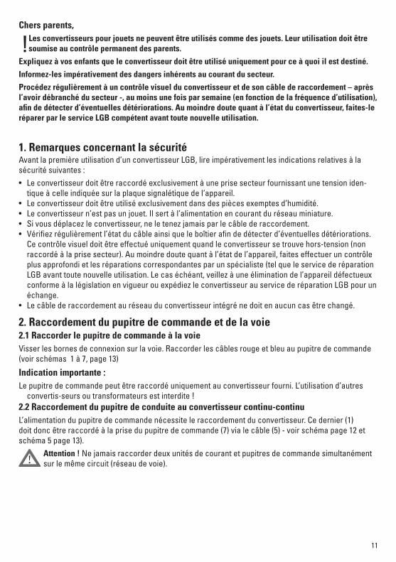
Chers parents,Les convertisseurs pour jouets ne peuvent être utilisés comme des jouets. Leur utilisation doit être soumise au contrôle permanent des parents.
Expliquez à vos enfants que le convertisseur doit être utilisé uniquement pour ce à quoi il est destiné.
Informez-les impérativement des dangers inhérents au courant du secteur.
Procédez régulièrement à un contrôle visuel du convertisseur et de son câble de raccordement – après l’avoir débranché du secteur -, au moins une fois par semaine (en fonction de la fréquence d’utilisation), afin de détecter d’éventuelles détériorations. Au moindre doute quant à l’état du convertisseur, faites-le réparer par le service LGB compétent avant toute nouvelle utilisation.
1. Remarques concernant la sécuritéAvant la première utilisation d’un convertisseur LGB, lire impérativement les indications relatives à la sécurité suivantes :• Le convertisseur doit être raccordé exclusivement à une prise secteur fournissant une tension iden-
tique à celle indiquée sur la plaque signalétique de l‘appareil.• Le convertisseur doit être utilisé exclusivement dans des pièces exemptes d’humidité.• Le convertisseur n’est pas un jouet. Il sert à l’alimentation en courant du réseau miniature.• Si vous déplacez le convertisseur, ne le tenez jamais par le câble de raccordement.• Vérifiez régulièrement l’état du câble ainsi que le boîtier afin de détecter d’éventuelles détériorations.
Ce contrôle visuel doit être effectué uniquement quand le convertisseur se trouve hors-tension (non raccordé à la prise secteur). Au moindre doute quant à l’état de l’appareil, faites effectuer un contrôle plus approfondi et les réparations correspondantes par un spécialiste (tel que le service de réparation LGB avant toute nouvelle utilisation. Le cas échéant, veillez à une élimination de l’appareil défectueux conforme à la législation en vigueur ou expédiez le convertisseur au service de réparation LGB pour un échange.
• Le câble de raccordement au réseau du convertisseur intégré ne doit en aucun cas être changé.
2. Raccordement du pupitre de commande et de la voie2.1 Raccorder le pupitre de commande à la voieVisser les bornes de connexion sur la voie. Raccorder les câbles rouge et bleu au pupitre de commande (voir schémas 1 à 7, page 13)
Indication importante :Le pupitre de commande peut être raccordé uniquement au convertisseur fourni. L’utilisation d’autres
convertis-seurs ou transformateurs est interdite !2.2 Raccordement du pupitre de conduite au convertisseur continu-continuL’alimentation du pupitre de commande nécessite le raccordement du convertisseur. Ce dernier (1) doit donc être raccordé à la prise du pupitre de commande (7) via le câble (5) - voir schéma page 12 et schéma 5 page 13).
Attention ! Ne jamais raccorder deux unités de courant et pupitres de commande simultanément sur le même circuit (réseau de voie). !
!
12
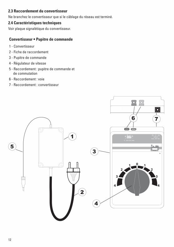
2.3 Raccordement du convertisseurNe branchez le convertisseur que si le câblage du réseau est terminé.
2.4 Caractéristiques techniquesVoir plaque signalétique du convertisseur.
Convertisseur • Pupitre de commande
1 - Convertisseur 2 - Fiche de raccordement 3 - Pupitre de commande 4 - Régulateur de vitesse 5 - Raccordement : pupitre de commande et de commutation 6 - Raccordement : voie 7 - Raccordement : convertisseur
2 10 - 20V DC max.
INPUTmax. 25V DC
5
1
2
3
4
6 7
13
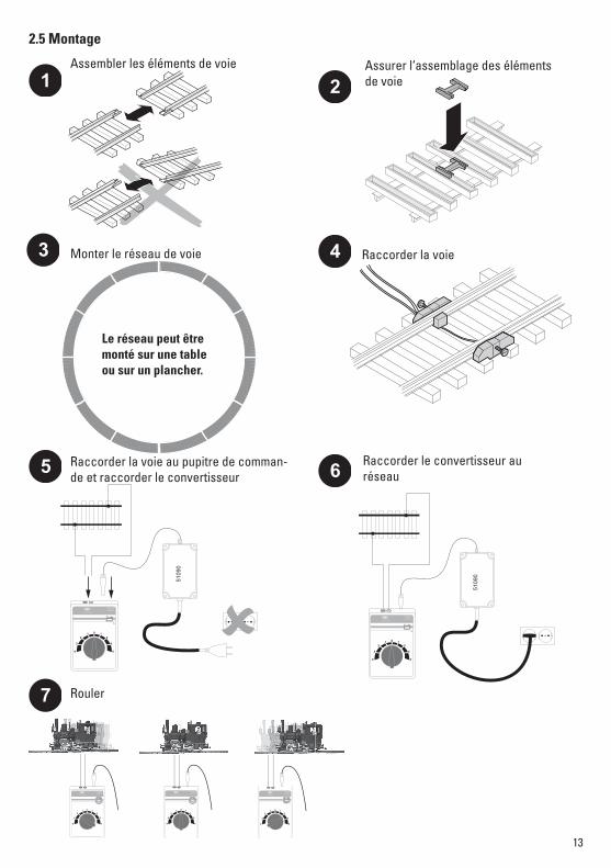
2.5 Montage
1 2
3 4
5 6
7
2 10 - 20V DC max.
INPUTmax. 25V DC
5109
0
2 10 - 20V DC max.
INPUTmax. 25V DC
5109
0
2 10 - 20V DC max.
INPUTmax. 25V DC
2 10 - 20V DC max.
INPUTmax. 25V DC2 1
0 - 20V DC max.
INPUTmax. 25V DC
Le réseau peut être monté sur une table ou sur un plancher.
Assembler les éléments de voie Assurer l‘assemblage des éléments de voie
Monter le réseau de voie Raccorder la voie
Raccorder la voie au pupitre de comman-de et raccorder le convertisseur
Rouler
Raccorder le convertisseur au réseau
14
3. Court-circuit ou surchargeProtection contre les surcharges
En cas de surcharge ou de court-circuit, le convertisseur est protégé une protection contre les sur-chages intégrée. Celui-ci provoque l‘arrêt de toutes les locomotives, l’extinction de toutes les lampes sous tension et empêche la commutation des articles électromagnétiques.Nous vous conseillons alors de procéder de la manière suivante :
1. Débranchez le convertisseur de la prise secteur.2. Recherchez la cause du court-circuit sur le réseau et remédiez au problème.3. A bout d’une minute environ, le protection contre les surcharges revient en état d’exploitation. Après
ce laps de temps, vous pouvez donc rebrancher le convertisseur.Si le convertisseur s’éteint à nouveau sans que vous ayez pu détecter de court-circuit, il s‘agit sans doute d‘une surcharge du convertisseur. Dans ce cas, il vous faut réduire le nombre de consommateurs reliés à ce convertisseur.
4. Dysfonctionnements• Si la locomotive ne marche pas, vérifiez que les connexions (voir montage, page X) sont correctes ou
que l’isolation du câble n’est pas coincée, respectivement que le convertisseur est bien branché au secteur.
• Si la locomotive est endommagée, excluez-la également de l’exploitation. Si un autre véhicule est endommagé, retirez-le également du train et mettez-le de côté.
5. Nettoyage et entretien• Vérifiez que les essieux ne soient pas encrassés (cheveux ou poussière) et nettoyez-les, au besoin à
l’aide d’une pincette.• Le train peut être nettoyé à l’aide d’un chiffon sec et lisse.• Vous trouverez d’autres conseils d’entretien sur la notice de votre locomotive.
6. EliminationIndications relatives à la protection de l’environnement : Les produits marqués du signe représentant une poubelle barrée ne peuvent être éliminés en fin de vie via les ordures ménagères normales, mais doivent être remis à un centre de collecte pour le recyclage des appareils électriques et électroniques. Le symbole figurant sur le produit lui-même, la notice d’utilisation ou l’emballage l’indique. Les matériaux sont recyclables selon leur marquage.
Avec le recyclage, la récupération des matériaux ou autres formes de valorisation de vieux appareils, vous contribuez sensiblement à la protection de notre environnement. Renseignez-vous auprès de votre municipalité sur les centres compétents pour le traitement des déchets.
7. GarantieGarantie légale et garantie contractuelle conformément au certificat de garantie ci-joint.• Pour toute réparation ou remplacement de pièces, adresses-vous à votre détaillant-spécialiste
Märklin. Gebr. Märklin & Cie. GmbH Reparaturservice Stuttgarter Str. 55 - 57 73033 Göppingen Deutschland Tel: +49 7161 608 222 E-Mail: [email protected]
15
Beste ouders,
! Netadapters voor speelgoed zijn niet geschikt om als speelgoed gebruikt te worden. Het gebruik dient onder voortdurend toezicht van de ouders te gebeuren.
Wijs uw kinderen er absoluut op, om de netadapter uitsluitend te gebruiken waarvoor deze bestemt is.
Wijs uw kinderen op de gevaren van de netspanning uit de wandcontactdoos.
Controleer op regelmatige tijden (afhankelijk van de intensiteit van het gebruik) maar minstens 1 x per week de toestand van de kabel en de behuizing van de netadapter op beschadigingen. Voer deze optische controle alleen uit als de netadapter uit de wandcontactdoos is genomen. Bij het geringste verdacht van een beschadiging mag de netadapter pas weer gebruikt worden na hersteld te zijn door het LGB service centrum.
1. VeiligheidsaanwijzingenLees eerst de volgende veiligheidsaanwijzingen aandachtig door voordat u de LGB netadapter gaat gebruiken• De netadapter mag alleen aangesloten worden op een wandcontactdoos waarvan de netspanning
overeenkomt met de op het typeplaatje van de adapter aangegeven netspanning.• De netadapter is uitsluitend geschikt voor het gebruik in droge ruimtes.• De netadapter is geen speelgoed. Het dient als stroomvoorziening voor de modelbaan.• Bij het verplaatsen mag de netadapter niet aan de aansluitkabel vastgehouden worden.• Controleer regelmatig de toestand van de kabel en de behuizing van de netvoedingadapter op be-
schadigingen. Deze optische controle mag alleen uitgevoerd worden als de netvoedingadapter uit de wandcontactdoos is genomen. Bij het geringste verdacht van een beschadiging mag de netvoedingad-apter niet meer gebruikt worden en dient eerst grondig gecontroleerd en hersteld te worden door een vakman (bijv. LGB service centrum) Na herstelling kan het apparaat weer worden gebruikt. Indien de netvoedingadapter niet meer hersteld kan worden, dient men deze op de juiste wijze af te voeren of ter omruil aan te bieden bij het LGB service centrum.
• De vaste aansluitkabel die de netvoedingadapter met de modelbaan verbind, mag niet veranderd worden.
2. Rijregelaar aansluiten en opbouw van de rails2.1 Rijregelaar aan de rails aansluitenAansluitklemmen aan de rails vastschroeven. De rode en blauwe draad aan de rijregelaar aansluiten (zie afb. 1-7, pag. 17)
Belangrijke aanwijzing:De rijregelaar mag alleen aan de meegeleverde netadapter aangesloten worden. Het gebruik van andere adapters of transformatoren is niet toegestaan!
2.2 Rijregelaar aan de netadapter aansluitenDe rijregelaar heeft de netadapter nodig voor de stroomvoorziening. Hiervoor hoeft alleen het snoer (5) van de netadapter (1) in de stekerbus van de rijregelaar (7) gestoken te worden (zie afb. pag.17, afb 5 pag.16).
!Voorzichtig! Er mogen nooit, gelijktijdig, twee netadapters of rijregelaars in dezelfde stroomkring (railovaal) aangesloten zijn.
16
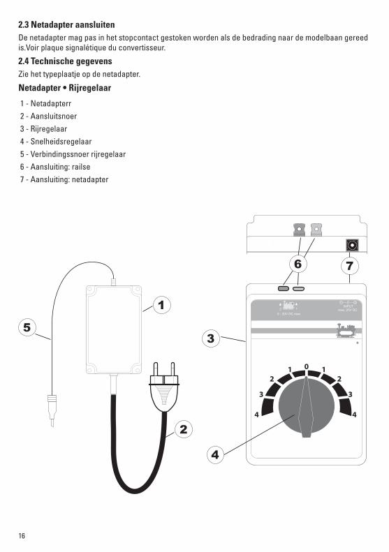
2.3 Netadapter aansluitenDe netadapter mag pas in het stopcontact gestoken worden als de bedrading naar de modelbaan gereed is.Voir plaque signalétique du convertisseur.
2.4 Technische gegevensZie het typeplaatje op de netadapter.
Netadapter • Rijregelaar
1 - Netadapterr 2 - Aansluitsnoer 3 - Rijregelaar 4 - Snelheidsregelaar 5 - Verbindingssnoer rijregelaar 6 - Aansluiting: railse 7 - Aansluiting: netadapter
2 10 - 20V DC max.
INPUTmax. 25V DC
5
1
2
3
4
6 7

17
2.5 Opbouw
1 2
3 4
5 6
7
2 10 - 20V DC max.
INPUTmax. 25V DC
5109
0
2 10 - 20V DC max.
INPUTmax. 25V DC
5109
0
2 10 - 20V DC max.
INPUTmax. 25V DC
2 10 - 20V DC max.
INPUTmax. 25V DC2 1
0 - 20V DC max.
INPUTmax. 25V DC
De eerste opbouw kan op een tafel of op de vloer worden uitgelegd.
Rails in elkaar steken Rails vergrendelen
Rails opbouwen Rails aansluiten
Rails aan de rijregelaar en de netadapter aansluiten
Rijden
Netadapter aan het net aansluiten
18
3. Kortsluiting of overbelastingOverbelastingbeveiligingEen ingebouwde overbelastingbeveiliging beschermt de netadapter bij overbelasting of kortsluitingen tegen beschadiging. De locs blijven allemaal stilstaan, magneet artikelen zijn niet meer te schakelen en alle aangesloten lampen doven.
De volgende werkwijze is aanbevolen1. Trek de netadapter uit het stopcontact.2. Zoek de kortsluiting in de modelbaan op en herstel deze.3. De overbelastingbeveiliging komt na ca. 1 minuut weer terug in de bedrijfstoestand. Na het verlopen
van deze wachttijd kan de netadapter weer in bedrijf genomen worden.Herhaald het afschakelen van de netadapter zich, zonder dat er een kortsluiting gevonden kan worden, dan is de netadapter overbelast. In dat geval dient het aantal der aangesloten verbruikers verminderd te worden.
4. Storingen• Rijdt de loc niet, controleer dan of de aansluitingen (zie opbouw) juist zijn of de draadisolatie niet is
ingeklemd in de aansluitklem en de netadapter in het stopcontact is gestoken.• Als de locomotief is beschadigd, de locomotief niet meer gebruiken. Is een ander voertuig beschadigd,
dan deze uit de trein nemen en niet meer gebruiken.
5. Reiniging en onderhoud • Controleer of zich geen haren of vuil bevinden om de assen en verwijder deze verontreiniging even-
tueel met behulp van een pincet van de assen.• De trein kan met een droge, niet pluizende doek of een zachte kwast gereinigd worden.• Verdere onderhoudswerkzaamheden vindt u in de gebruiksaanwijzing van uw locomotief.
6. Afdanken Milieu-informatie: producten, die met de doorgestreepte afvalcontainer zijn gemarkeerd, mogen aan het einde van hun levensduur niet met het normale huisvuil meegegeven worden, maar moeten op een verzamelpunt voor de recycling van elektrische en elektronische apparatuur afgegeven worden. Het symbool op het product, op de handleiding of op de verpakking geeft dit aan. De materialen worden gerecycled in overeenstemming met hun
identificatie. Met het hergebruik van de grondstoffen of andere vormen van het hergebruik van oude apparatuur levert u een belangrijke bijdrage aan de bescherming van ons milieu. Neem contact op met uw gemeente voor een bevoegde plaatselijke inzamelplaats.
7. GarantieWaarborg en garantie volgens bijgevoegd garantiebewijs.• Voor reparaties kunt u zich wenden tot uw Märklin dealer of tot Gebr. Märklin & Cie. GmbH Reparaturservice Stuttgarter Str. 55 - 57 D-73033 Göppingen Deutschland Tel: +49 7161 608 222 E-Mail: [email protected]
19
Queridos padres:Las fuentes de alimentación conmutadas para juguetes no son idóneas para utilizarlas como un juguete más. El uso de las mismas debe ser vigilado permanentemente por los padres.
No olvidar recordar a los niños que deben utilizar la fuente de alimentación conmutada exclusivamente para la finalidad prevista.
Siempre recordar a los niños los peligros que representa la red eléctrica doméstica.
Inspeccionar visualmente con regularidad (en función de la frecuencia de juego con la maqueta), al menos una vez por semana, la fuente de alimentación y su cable de conexión con el dispositivo aislado de la red eléctrica doméstica para detectar posibles daños. Ante la más mínima sospecha de daños, no está permitido continuar utilizando la fuente de alimentación conmutada hasta que no haya sido reparada por el servicio de reparación de LGB.
1. Advertencias de seguridadEs obligatorio leer las siguientes advertencias de seguridad antes de utilizar por primera vez la fuente de alimentación conmutada LGB:• Está permitido conectar la fuente de alimentación conmutada únicamente a un enchufe de red cuya
tensión de red coincida con la indicada en la placa de características de la fuente de conmutación conmutada.
• La fuente de alimentación conmutada está destinada exclusivamente para su uso en recintos secos. • La fuente de alimentación conmutada no es un juguete. Sirve para la alimentación eléctrica de una
maqueta de trenes. • A la hora de transportar la fuente de alimentación eléctrica no está permitido hacerlo por el cable de
conexión de la misma. • Revise con regularidad el estado del cable y la carcasa para detectar posibles daños. Está permitido
realizar esta revisión visual únicamente con la fuente de alimentación conmutada extraída del enchufe de la red doméstica. Ante la más mínima sospecha de daños, no está permitido seguir utilizando la fuente de alimentación conmutada hasta que ésta haya sido sometida a una revisión profunda y repa-rada por un centro técnico especializado (p. ej., el servicio de reparación de LGB). En tal caso, asegure que la eliminación de la fuente de alimentación conmutada se realice de manera profesional o envíela al servicio de reparación de LGB para su sustitución.
• No está permitido modificar el cable de conexión montado fijo entre la fuente de alimentación conmu-tada y la maqueta de trenes.
2. Conexión del pupitre de conducción y montaje de las vías2.1 Conexión del pupitre de conducción a la víaAtornillar los bornes de conexión a la vía. Conectar los cables rojo y azul al pupitre de conducción (véan-se figuras 1-7, página 21).Nota importante:
Está permitido conectar el pupitre de conducción únicamente a la fuente de alimentación conmutada que se adjunta. ¡No está permitido utilizar otras fuentes de alimentación conmutadas o transformadores!
2.2 Conexión del pupitre de conducción a la fuente de alimentación conmutadaEl pupitre de conducción necesita la fuente de alimentación conmutada para la alimentación de potencia. Por este motivo debe enchufarse en la hembrilla del pupitre de conducción (7) únicamente la fuente de alimentación conmutada (1) con el cable (5) (véase figura en pág. 21, figura 5 en pág. 20).
! ¡Precaución! No está permitido conectar simultáneamente dos fuentes de alimentación y pupitres de conducción a idéntico circuito (circuito de vía).
!

20
2.3 Conexión de la fuente de alimentación conmutada No está permitido enchufar la fuente de alimentación conmutada en el enchufe hasta que esté terminado el cableado de la maqueta.
2.4 Datos técnicosVéase la placa de características en la fuente de alimentación conmutada.
Fuente de alimentación conmutada • Pupitre de conducción
1 - Fuente de alimentación conmutada 2 - Cable de conexión 3 - Pupitre de conducción 4 - Regulador de velocidad5 - Cable de interconexión de pupitre de conducción 6 - Conexión: Vía7 - Conexión: Fuente de alimentación conmutada
2 10 - 20V DC max.
INPUTmax. 25V DC
5
1
2
3
4
6 7
21
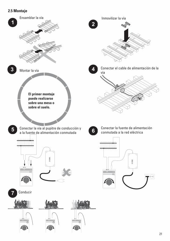
2.5 Montaje
1 2
3 4
5 6
7
2 10 - 20V DC max.
INPUTmax. 25V DC
5109
0
2 10 - 20V DC max.
INPUTmax. 25V DC
5109
0
2 10 - 20V DC max.
INPUTmax. 25V DC
2 10 - 20V DC max.
INPUTmax. 25V DC2 1
0 - 20V DC max.
INPUTmax. 25V DC
El primer montaje puede realizarse sobre una mesa o sobre el suelo.
Ensamblar la vía Inmovilizar la vía
Montar la vía Conectar el cable de alimentación de la vía
Conectar la vía al pupitre de conducción y a la fuente de alimentación conmutada
Conducir
Conectar la fuente de alimentación conmutada a la red eléctrica
22
3. Cortocircuito o sobrecargaProtección contra sobrecarga Una protección contra sobrecarga integrada protege la fuente de alimentación conmutada en el caso de sobrecarga o cortocircuito, evitando que resulte dañada. Todas las locomotoras permanecen en reposo, ya no es posible conmutar artículos magnéticos y se apagan todos los testigos conectados.
Se recomienda el siguiente procedimiento:1. Extraiga la fuente de alimentación conmutada del enchufe.2. Localice el cortocircuito en la maqueta y elimínelo.3. La protección contra sobrecarga se rearma al cabo de aprox. 1 minuto y vuelve a estar operativa. Una vez transcurrido este margen de tiempo se puede poner de nuevo en servicio la fuente de alimentación conmutada.Si se repite la desconexión de la fuente de alimentación conmutada sin que pueda localizarse un corto-circuito, existe una sobrecarga de la fuente de alimentación conmutada. En este caso debe reducirse el número de consumidores conectados a esta fuente de alimentación conmutada.
4. Anomalías funcionales • Si la locomotora no se pone en marcha, compruebe si las conexiones (véase Montaje) se han realizado
correctamente o si se ha pillado el aislamiento del cable o bien si la fuente de alimentación conmutada está enchufada en el enchufe.
• Si la locomotora está dañada, dejar de utilizar la locomotora. Si otro vehículo está dañado, retirarlo del tren y dejar de utilizarlo.
5. Limpieza y mantenimiento• Compruebe si hay cabello o suciedad en los ejes y elimine esta suciedad de los ejes, si es preciso con
ayuda de unas pinzas. • Es posible limpiar el tren con un paño seco sin hilachas o un pincel suave.• En las instrucciones de empleo de la locomotora se describen otros trabajos de mantenimiento.
6. EliminaciónConsejos para la protección del medio ambiente: los productos identificados con un contene-dor de basura tachado no deben eliminarse a través del servicio de recogida de la basura doméstica normal, sino que deben entregarse en un punto de recogida para reciclaje de dispositivos eléctricos y electrónicos. El símbolo que figura en el producto, las instrucciones de empleo o el embalaje hacen referencia a tal circunstancia. Los materiales deben reciclarse
conforme a su identificación. Con el reciclaje, la clasificación de materiales y otras formas de reapro-vechamiento de dispositivos usados realizamos una importante aportación a la protección de nuestro medio ambiente. Consulte en su municipio dónde se encuentra el centro de recogida competente.
7. GarantíaLa garantía legal y la garantía del fabricante se rigen por lo establecido en el documento de garantía adjunto.• Para cualquier reparación, por favor envíe el dispositivo a su distribuidor profesional de Märklin o a
Gebr. Märklin & Cie. GmbH Reparaturservice Stuttgarter Str. 55 - 57 73033 Göppingen Deutschland Tel: +49 7161 608 222 E-Mail: [email protected]
23
Cari genitori,
! gli alimentatori “switching” da rete per i giocattoli non sono adatti alla finalità di essere utilizzati come un giocattolo. Il loro utilizzo deve avvenire sotto una costante sorveglianza dei genitori.
Vogliate avvertire assolutamente i Vostri bimbi di questo fatto, ossia di utilizzare l’alimentatore “swit-ching” da rete solo in modo corrispondente alla sua destinazione.
Vogliate avvertire assolutamente i Vostri bimbi dei pericoli della rete di corrente domestica.
Vogliate verificare visivamente a intervalli di tempo regolari (a seconda della rispettiva frequenza dell’esercizio di gioco), come minimo 1 volta per settimana, l’alimentatore “switching” da rete ed il suo conduttore di collegamento contro i danneggiamenti, nella condizione distaccata dalla rete della cor-rente domestica. In caso del più piccolo sospetto di un danneggiamento, tale alimentatore “switching” da rete può venire ulteriormente utilizzato solo dopo la riparazione tramite il Servizio Riparazioni LGB.
1. Avvertenze di sicurezzaVogliate leggere assolutamente le seguenti avvertenze di sicurezza prima del primo impiego di un alimen-tatore “switching” da rete LGB:• L’alimentatore “switching” da rete deve venire collegato soltanto ad una presa di rete elettrica con la
tensione di rete specificata sulla targhetta dei dati dell’alimentatore “switching” da rete.• Tale alimentatore “switching” da rete è progettato esclusivamente per l’utilizzo in ambienti asciutti.• Tale alimentatore “switching” da rete non è affatto un giocattolo. Esso serve all’alimentazione di cor-
rente dell’impianto di ferrovia in miniatura.• Durante il trasporto dell’alimentatore “switching” da rete questo non deve mai venire sorretto dal cavo
di connessione.• Vogliate verificare regolarmente le condizioni di tale cavo nonché l’involucro per i danneggiamenti.
Questa verifica visuale deve essere condotta soltanto quando l’alimentatore “switching” da rete è rimosso dalla presa ad innesto della rete domestica. In caso del più minuscolo sospetto di un dann-eggiamento l’alimentatore “switching” da rete deve venire nuovamente impiegato soltanto dopo una radicale verifica e riparazione tramite un laboratorio specialistico (ad es. il Servizio Riparazioni LGB). Vogliate in questo caso provvedere ad uno smaltimento professionale oppure inviate l’alimentatore “switching” da rete al Servizio Riparazioni LGB per la sostituzione.
• Il cavo di collegamento applicato in modo fisso dall’alimentatore “switching” da rete all’impianto non deve venire modificato.
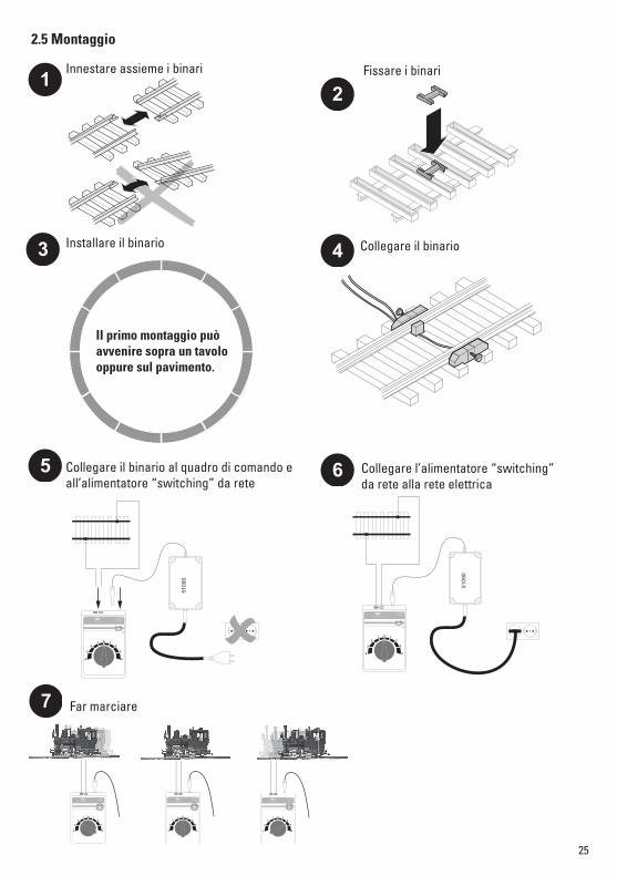
2. Collegamento del quadro di comando e montaggio dei binari2.1 Collegamento del quadro di comando ai binariAvvitare i morsetti di collegamento al binario. Collegare il cavetto rosso e blu al quadro di comando (si vedano le figure 1-7, pagina 25).
Avvertenza importante:Il collegamento del quadro di comando può avvenire soltanto all’accluso alimentatore “switching” da rete. Un impiego di altri alimentatori “switching” da rete oppure trasformatori non è ammissibile!
2.2 Collegamento del quadro di comando all’alimentatore “switching” da reteIl quadro di comando richiede tale alimentatore “switching” da rete per l’alimentazione di potenza. Perta-nto deve venire innestato soltanto l’alimentatore “switching” da rete (1) con il cavo (5) nella boccola del quadro di comando (7) – (si veda la figura a pag. 25, la figura 5 a pag. 24).
! Attenzione! Non possono mai essere collegati contemporaneamente due apparati da rete e quadri di comando allo stesso circuito di corrente (circuito di binario).
24
2 10 - 20V DC max.
INPUTmax. 25V DC
5
1
2
3
4
6 7
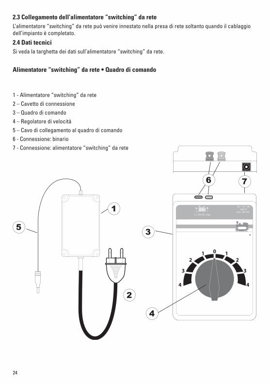
2.3 Collegamento dell’alimentatore “switching” da reteL’alimentatore “switching” da rete può venire innestato nella presa di rete soltanto quando il cablaggio dell’impianto è completato.
2.4 Dati tecniciSi veda la targhetta dei dati sull’alimentatore “switching” da rete.
Alimentatore “switching” da rete • Quadro di comando
1 - Alimentatore “switching” da rete2 – Cavetto di connessione3 – Quadro di comando4 – Regolatore di velocità5 – Cavo di collegamento al quadro di comando6 - Connessione: binario7 - Connessione: alimentatore “switching” da rete
25
12
3 4
5 6
7
2.5 Montaggio
2 10 - 20V DC max.
INPUTmax. 25V DC
5109
0
2 1
0 - 20V DC max.
INPUTmax. 25V DC
5109
0
2 10 - 20V DC max.
INPUTmax. 25V DC
2 10 - 20V DC max.
INPUTmax. 25V DC2 1
0 - 20V DC max.
INPUTmax. 25V DC
Il primo montaggio può avvenire sopra un tavolo oppure sul pavimento.
Innestare assieme i binari Fissare i binari
Installare il binario Collegare il binario
Collegare il binario al quadro di comando e all’alimentatore “switching” da rete
Collegare l’alimentatore “switching” da rete alla rete elettrica
Far marciare
26
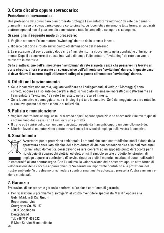
3. Corto circuito oppure sovraccaricoProtezione dal sovraccaricoUna protezione dal sovraccarico incorporata protegge l’alimentatore “switching” da rete dai danneg-giamenti in caso di sovraccarico oppure corto circuito. Le locomotive rimangono tutte ferme, gli apparati elettromagnetici non si possono più commutare e tutte le lampadine collegate si spengono.
Si consiglia il seguente modo di procedere:1. Vogliate staccare l’alimentatore “switching” da rete dalla presa a innesto.2. Ricerca del corto circuito sull’impianto ed eliminazione del medesimo.3. La protezione dal sovraccarico dopo circa 1 minuto ritorna nuovamente nella condizione di funziona-mento. Dopo il trascorrere di questo intervallo di tempo l’alimentatore “switching” da rete può venire reinserito in esercizio.Se la disattivazione dell’alimentatore “switching” da rete si ripete, senza che possa venire trovato un corto circuito, allora è presente un sovraccarico dell’alimentatore “switching” da rete. In questo caso si deve ridurre il numero degli utilizzatori collegati a questo alimentatore “switching” da rete.
4. Difetti nel funzionamento• Se la locomotiva non marcia, vogliate verificare se i collegamenti (si veda 2.5 Montaggio) sono
corretti, oppure se l’isolante dei cavetti è stato schiacciato insieme nei morsetti o rispettivamente se l’alimentatore “switching” da rete è innestato nella presa ad innesto.
• Se la locomotiva è danneggiata, non si impieghi più tale locomotiva. Se è danneggiato un altro rotabile, si rimuova questo dal treno e non lo si utilizzi più.
5. Pulizia e manutenzione• Vogliate controllare se sugli assali si trovano capelli oppure sporcizia e se necessario rimuovete questi
contaminanti dagli assali con l’ausilio di una pinzetta.• Il treno può venire pulito con un panno asciutto, esente da filamenti, oppure un pennello morbido.• Ulteriori lavori di manutenzione potete trovarli nelle istruzioni di impiego della vostra locomotiva.
6. SmaltimentoAvvertenze per la protezione ambientale: I prodotti che sono contraddistinti con il bidone della spazzatura cancellato alla fine della loro durata di vita non possono venire eliminati mediante i normali rifiuti domestici, bensì devono essere conferiti ad un apposito punto di raccolta per il riciclaggio di apparecchi elettrici ed elettronici. Il simbolo su tale prodotto, le istruzioni di impiego oppure la confezione dà avviso riguardo a ciò. I materiali costituenti sono riutilizzabili
in conformità al loro contrassegno. Con il riutilizzo, la valorizzazione delle sostanze oppure altre forme di valorizzazione delle vecchie apparecchiature Voi fornite un importante contributo alla protezione del nostro ambiente. Vi preghiamo di richiedere i punti di smaltimento autorizzati presso la Vostra amministra-zione municipale.
7. GaranziaPrestazioni di assistenza e garanzia conformi all’accluso certificato di garanzia.• Per riparazioni Vi preghiamo di rivolgerVi al Vostro rivenditore specialista Märklin oppure alla Gebr. Märklin & Cie. GmbH
Reparaturservice Stuttgarter Str. 55 - 57 73033 Göppingen Deutschland
Tel: +49 7161 608 222 E-Mail: [email protected]

27

Gebr. Märklin & Cie. GmbH Stuttgarter Str. 55 - 5773033 GöppingenGermanywww.lgb.de
195828/0614/Ha1EfÄnderungen vorbehalten
© by Gebr. Märklin & Cie. GmbH
Due to different legal requirements regarding electro-magnetic compa-tibility, this item may be used in the USA only after separate certification for FCC compliance and an adjustment if necessary.
Use in the USA without this certification is not permitted and absolves us of any liability. If you should want such certification to be done, please contact us – also due to the additional costs incurred for this.
www.maerklin.com/en/imprint.html