Embed Size (px)
Citation preview
To appear in SPIE 6275 (2006)
1
Instrumentation for the CCAT Telescope
G.J. Stacey*a, S.R. Golwalab, C.M. Bradfordc, C.D. Dowellc, G. Cortes-Medellina, T. Nikolaa, J. Zmuidzinasb, T.L. Hertera, S.J. Radfordb, J.P. Lloyda, A.W. Blaind, R.L Browna, D.B. Campbella, R.
Giovanellia, P. Goldsmithc, P.M. Harveye, C. Hendersona, W.D. Langerc, T. G. Phillipsb, A.C.S. Readheadd, D.P. Woodyf
aDepartment of Astronomy, Cornell University, Ithaca, NY 14853-6801
bDepartment of Physics, Caltech, Pasadena, CA 91125 cJet Propulsion Lab, Pasadena, CA 91109
dDepartment of Astronomy, Caltech, Pasadena, CA 91125 eDepartment of Astronomy, University of Texas, Austin TX 78712
fCaltech Owens Valley Radio Observatory, Big Pine, CA 91125
ABSTRACT We present a first cut instrument design package for the proposed 25 meter Cornell-Caltech Atacama Telescope (CCAT). The primary science for CCAT can be achieved through wide field photometric imaging in the short submillimeter through millimeter (200 μm to 2 mm) telluric windows. We present strawman designs for two cameras: a 32,000 pixel short submillimeter (200 to 650 μm) camera using transition edge sensed bare bolometer arrays that Nyquist samples (@ 350 μm) a 5’×5’ field of view (FoV), and a 45,000 pixel long wavelength camera (850 μm to 2 mm) that uses slot dipole antennae coupled bolometer arrays with wavelength dependent sampling that covers up to a 20’ square FoV. These are our first light instruments. We also anticipate “borrowed” instruments such as direct detection and heterodyne detection spectrometers will be available at, or nearly at first light. Keywords: submillimeter, astronomy, telescopes, bolometers, arrays, cameras, spectrometers
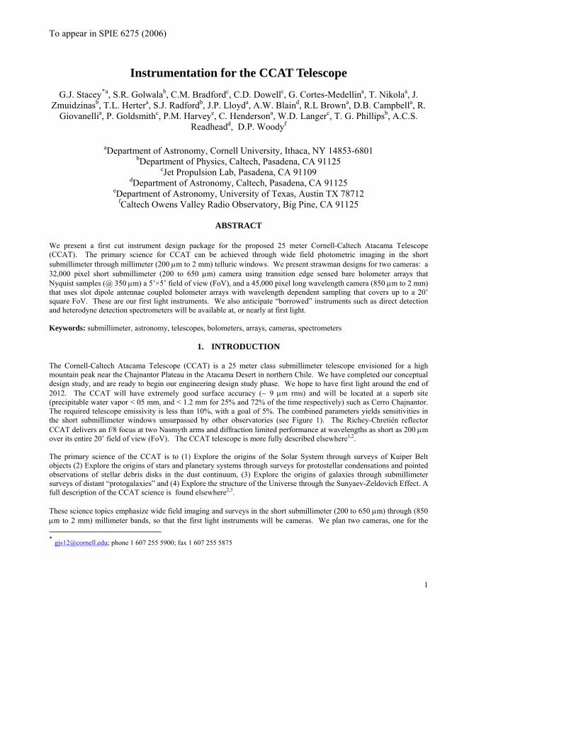
1. INTRODUCTION The Cornell-Caltech Atacama Telescope (CCAT) is a 25 meter class submillimeter telescope envisioned for a high mountain peak near the Chajnantor Plateau in the Atacama Desert in northern Chile. We have completed our conceptual design study, and are ready to begin our engineering design study phase. We hope to have first light around the end of 2012. The CCAT will have extremely good surface accuracy (~ 9 μm rms) and will be located at a superb site (precipitable water vapor < 05 mm, and < 1.2 mm for 25% and 72% of the time respectively) such as Cerro Chajnantor. The required telescope emissivity is less than 10%, with a goal of 5%. The combined parameters yields sensitivities in the short submillimeter windows unsurpassed by other observatories (see Figure 1). The Richey-Chretién reflector CCAT delivers an f/8 focus at two Nasmyth arms and diffraction limited performance at wavelengths as short as 200 μm over its entire 20’ field of view (FoV). The CCAT telescope is more fully described elsewhere1,2. The primary science of the CCAT is to (1) Explore the origins of the Solar System through surveys of Kuiper Belt objects (2) Explore the origins of stars and planetary systems through surveys for protostellar condensations and pointed observations of stellar debris disks in the dust continuum, (3) Explore the origins of galaxies through submillimeter surveys of distant “protogalaxies” and (4) Explore the structure of the Universe through the Sunyaev-Zeldovich Effect. A full description of the CCAT science is found elsewhere2,3. These science topics emphasize wide field imaging and surveys in the short submillimeter (200 to 650 μm) through (850 μm to 2 mm) millimeter bands, so that the first light instruments will be cameras. We plan two cameras, one for the
* [email protected]; phone 1 607 255 5900; fax 1 607 255 5875
To appear in SPIE 6275 (2006)
short submillimeter wavelengths, and the second for near mm wavelengths are part of the baseline project. The short wavelength camera (SWCam, Section 3)) has 32,000 TES silicon bolometers, and is fully sampled at 350 μm, covering a 5’×5’ FoV. The long wavelength camera (LWCam, Section 4) uses a slot dipole antennae coupled bolometers with various bands separated by using microstrip bandpass filters. Plate scales and pixel counts are wavelength dependent. The larger plate scales cover the entire 20’×20’ FoV. These cameras are challenging, but achievable through modest advances in the current array technologies. Polarimetry (Section 5) is a natural addition to the first light cameras.
2
Existing, previous generation instruments (e.g. direct and coherent detection spectrometers, polarimeters and far-IR cameras) developed for other facilities can be brought to CCAT to enhance the scientific yield of the two cameras. Although these existing instruments are incapable of accomplishing the primary CCAT science objectives, they will provide important supplementary capabilities, especially in the early years of operation. Polarimetry and borrowed spectrometers are outlined in Sections 5 and 6 respectively. Looking into the future, foreseeable instrument developments will greatly extend the CCAT science return for many years.
2. OVERVIEW
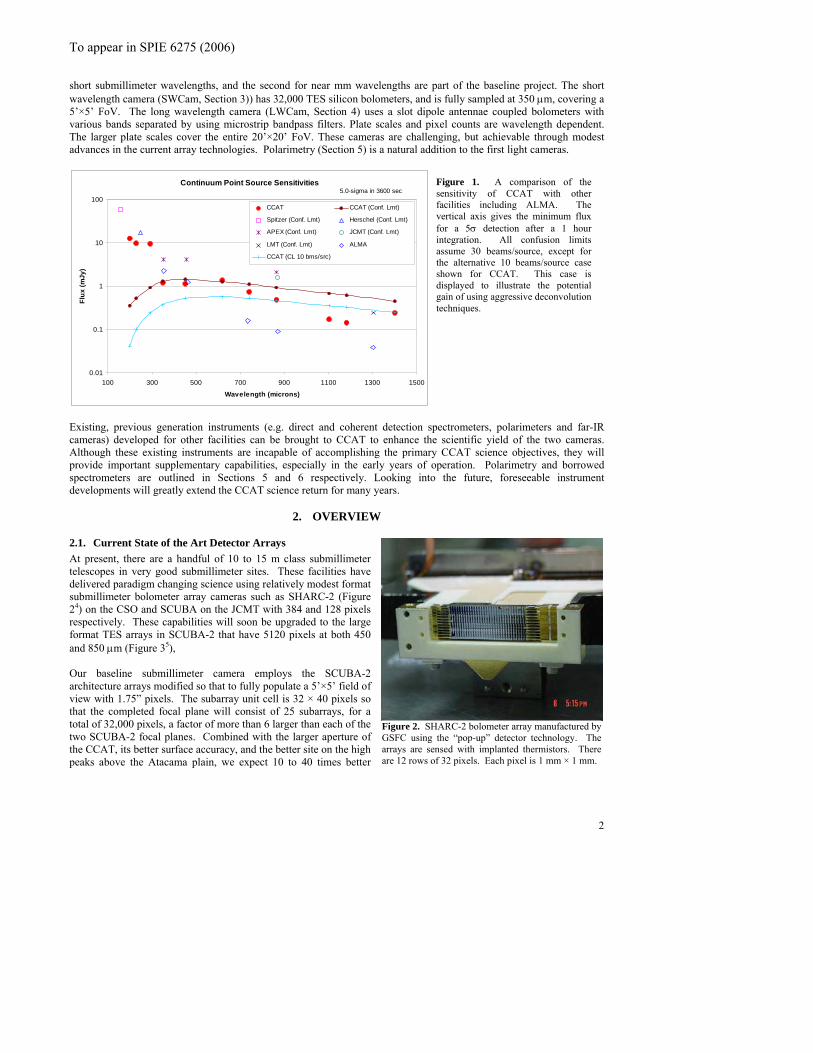
2.1. Current State of the Art Detector Arrays At present, there are a handful of 10 to 15 m class submillimeter telescopes in very good submillimeter sites. These facilities have delivered paradigm changing science using relatively modest format submillimeter bolometer array cameras such as SHARC-2 (Figure 24) on the CSO and SCUBA on the JCMT with 384 and 128 pixels respectively. These capabilities will soon be upgraded to the large format TES arrays in SCUBA-2 that have 5120 pixels at both 450 and 850 μm (Figure 35), Our baseline submillimeter camera employs the SCUBA-2 architecture arrays modified so that to fully populate a 5’×5’ field of view with 1.75” pixels. The subarray unit cell is 32 × 40 pixels so that the completed focal plane will consist of 25 subarrays, for a total of 32,000 pixels, a factor of more than 6 larger than each of the two SCUBA-2 focal planes. Combined with the larger aperture of the CCAT, its better surface accuracy, and the better site on the high peaks above the Atacama plain, we expect 10 to 40 times better
Continuum Point Source Sensitivities
0.01
0.1
1
10
100
100 300 500 700 900 1100 1300 1500
Wavelength (microns)
Flux
(mJy
)
CCAT CCAT (Conf. Lmt)
Spitzer (Conf. Lmt) Herschel (Conf. Lmt)
APEX (Conf. Lmt) JCMT (Conf. Lmt)
LMT (Conf. Lmt) ALMA
CCAT (CL 10 bms/src)
Figure 1. A comparison of the sensitivity of CCAT with other facilities including ALMA. The vertical axis gives the minimum flux for a 5σ detection after a 1 hour integration. All confusion limits assume 30 beams/source, except for the alternative 10 beams/source case shown for CCAT. This case is displayed to illustrate the potential gain of using aggressive deconvolution techniques.
5.0-sigma in 3600 sec
Figure 2. SHARC-2 bolometer array manufactured by GSFC using the “pop-up” detector technology. The arrays are sensed with implanted thermistors. There are 12 rows of 32 pixels. Each pixel is 1 mm × 1 mm.

To appear in SPIE 6275 (2006)
3
.
.2. Overall Instrument Requirements st be remotely
.3. Telescope Pointing and Jitter Requirements the
econds) times
.4. Why Two Cameras Instead of One? age to creating an instrument that can image at 350 and 850 μm
eld two
aster at
• ars
• g
• ith the different
3. SHORT WAVELENGTH CAMERA
he Short Wavelength Camera (SWCam) will deliver diffraction limited imaging in the short submillimeter (200, 350,
3.1. Instrument Requirements e goals, the SWCam requirements are:
sensitivity per beam than prior facilities at 350 μm. Combined with the larger format arrays, we expect factors of hundreds or even thousands improvement in mapping speed 2All facility instruments on the CCAT muoperable, and use only closed cycle refrigerators. The SWCam and LWCam cameras will couple to the telescope at the Nasmyth f/8 focus, one on each arm. This arrangement maximizes the efficiency of use of prevailing weather conditions. The cameras require re-imaging fore-optics that could be used for other instruments as well. Other instruments will likely be coupled through a quaternary flat at each focus in which case there would be 3 ports times 2, or 6 positions. 2The pointing and tracking jitter requirements forCCAT can be calculated in a straight forward manner2. Here we define pointing as the error in the boresight position, caused by, for example, an error in a slew from a pointing source, or an incorrect guider offset. Jitter are random deviations in the pointing that may occur on short (sor atmospheric “seeing”. For a fully sampled camera, pointing errors need not affect sensitivity, but jitter will. For slit grating spectrometers such as ZEUS and Z-spec, or heterodyne spectrometers, both types of errors will degrade performance. To not degrade sensitivity by more than 10%, the pointing requirement is 0.61” in each dimension for a 350 μm slit spectrometer. The jitter requirement is similar: the RMS jitter must be less than 0.66” for 90% of peak performance. If both of these errors contribute equally, a mean offset and RMS jitter error of 0.45” (each) degrades the 350 μm performance by 10%. The requirements naturally scale with wavelength: with no jitter, pointing requirement = 0.61” (λ/350 μm) , with jitter pointing requirement = 0.46” (λ/350 μm).
Figure 3. Functional layout for the 5120 element arrays in SCUBA-2. The array is composed of 4 - 32×40 pixel sub-arrays butted together. These arrays employ TES readouts and a SQUID multiplexer. The arrays are manufactured by NIST (W Duncan, K. Irwin personal communication)
cales such as jitter in the tracking mechanisms,
2It can be argued that there is a science advantsimultaneously. This would ensure near perfect registration between the two wavelengths and immediately yipoints on the spectral energy distribution (SED) for astrophysical sources. However, we rejected this idea since:
• The expected sensitivities, and SEDs are not well matched. The confusion limit is reached 3 times f850 μm than at 350 μm so that the 850 μm exposure would be “finished” much sooner than that at 350 μm. The technologies for detector arrays are different at the two wavelengths. An optically coupled array appebest in the short submillimeter, while antenna coupled arrays have better promise at the longer wavelengths. The image quality requirements are much more stringent at the shorter wavelengths. Transmissive reimaginoptics easily delivers the requisite image quality with acceptable losses in the short submillimeter. However, transmissive optics would have unacceptably large emissivity for work in the near mm bands. Array costs are the largest single capital item for the instruments describe here. Folded in warray technologies, it is logical to construct separate instruments for work at 350 and 850 μm.
T450, and 620 μm) telluric windows. Each of these windows is accessible via a cryogenic filter wheel containing bandpass filters well matched to the telluric windows. The baseline design has a 5’ × 5’ field of view, is fully sampled at 350 μm, and is coupled to the telescope through a Germanium lens re-imaging system.
To accomplish our primary scienc

To appear in SPIE 6275 (2006)
4
indows. Bandpass filters to be optimized for
2. rn in the
3. tum efficiency.
.2. Field of View
igned to deliver a 20’ FoV. However, to fully populate this field would require ~ 500,000 pixels
years of operation. nto a 350 μm
3. ts that 32,000 pixels is a reasonable goal for array size. This
4. nt of 4 or 5 identical cameras covering 5’ each,
3.3. etailed Design
ocal plane that Nyquist samples a diffraction limited image, must have a final f/# given by 1.22
e.
e investigated both fully reflective and transmissive optics for the re-imaging fore-optics. The reflective design has the
transmissive system is easily designed with the 5’ FoV imaged into a compact 0.7 × 1.0 m dewar, with a 25 cm dewar
3.2. Optical Design. The baseline design employs germanium lenses. Germanium lenses are commercially available
he system is quite simple (Figure 4): the first element takes the f-cone of the 5’ FoV of the telescope and collimates it
1. Broadband photometry in the 350, 450, and 620 μm telluric wgreatest sensitivity to continuum sources as determined by the telluric and instrument transmission. Diffraction limited imaging at the primary survey band (350 μm) so as to maximize the science retuinterplay between array size (numbers of pixels), field of view, and source confusion. Total instrument throughput requirement is 20% (goal is 40%) including detector quan
4. Background limited performance at each wavelength even under the best observing conditions.
3The telescope is deswhich would be extremely expensive using current technologies. Next generation technologies will likely reduce this cost significantly, so development of a mega-pixel camera is logically delayed as second generation instrumentation. We are designing our baseline submillimeter camera to have a 5’ FoV for four reasons.
1. The primary science can be delivered with a 5’ FoV camera within the first 3 2. The telescope delivers a 1.17 meter image for a 20’ FoV which is quite challenging to couple i
diffraction limited background limited camera. The current, and near future technology suggesdelivers Nyquist sampled images over a 5’ × 5’ FoV at 350 μm. Much of the 20’ FoV could be imaged through clever arrangemeproviding a natural growth path.
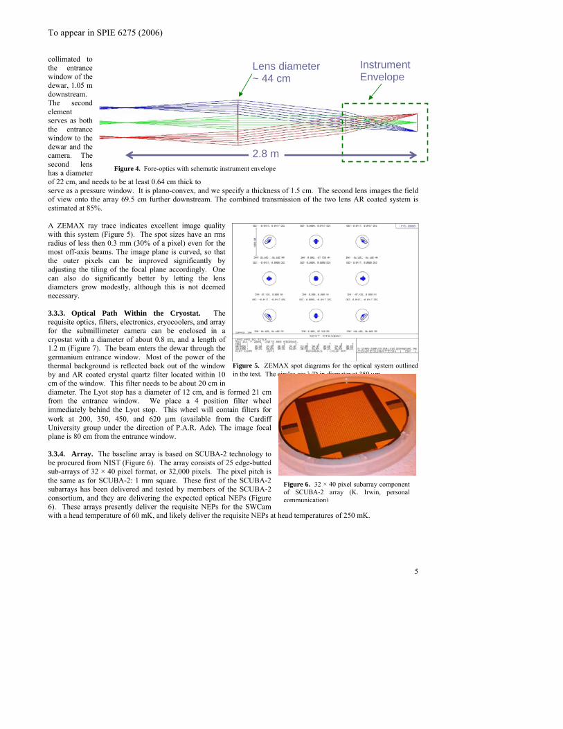
D3.3.1. Fore-optics A f× f/# λ/2 = x where x is the physical dimension of individual pixels. The proposed NIST detector arrays have 1mm pitch, so that at 350 μm, the final f/# must be f/4.6. The telescope delivers f/8, so that we must re-image the focal planThe re-imaging process also enables formation of a pupil (image of the primary mirror) within the camera itself. A cold Lyot stop is placed at this pupil minimizing extraneous background power. Wadvantage that it maximizes throughput, and minimizes emissivity. An optical design was attained using the ZEMAX ray-tracing program that delivers the requisite image quality over the entire 20’ FoV of the telescope. However, this design requires 4 m class off-axis paraboloids, and results in a dewar that is roughly 8 m × 3 m in size. For the first light instrument, the more modest 5’ FoV focal plane can be properly imaged into a more modest 3 m × 1.5 meter dewar, but the reimaging mirrors is still formidable 3 m class paraboloids. We therefore investigated the use of transmissive optics. Awindow. Lens diameters are modest at about 44 cm or less. However, selection of lens materials is challenging, as bulk absorption lessens system transmission and increases system emissivity. Unfortunately, in the short submillimeter bands system emissivity will never be less than about 30% due to contributions from the sky, so that modest (~10%) emissivity of the lens material is acceptable, and we can use transmissive optics. We found a variety of materials that would work as lenses including polyethylene, quartz, sapphire, silicon, and germanium. The selection criterion was essentially the extinction coefficient, but other important issues include material properties (environmental (water damage), structural (use as a window)), cost, and the availability of suitable anti-reflection coatings. 3.with standard sizes to 35 cm diameter (e.g.Umicore Corp: www.optics.umicore.com). Bulk absorption is of the order 7%. Broad band anti-reflection coatings can be achieved by tapering the index at the surface. We are investigating the use of micromachined pyramid-like structures at Caltech/JPL. Such structures promise to deliver excellent AR coatings good from the short wavelength (200 μm) through long wavelength 650 μm design range of SWCam. The total transmission of such a germanium lens is estimated in be in excess of 90%. Twith a beam size of 13.5 cm. The second element is near the pupil of the first element, and takes the collimated light and images it at the focal plane at f/4.8. The first element is a 44 cm diameter plano-convex lens, with a radius of curvature of 350 cm and a center thickness of 2.5 cm. This lens is placed 1.10 m back from the Nasmyth focus and sends a
To appear in SPIE 6275 (2006)
both
ness of 1.5 cm. The second lens images the field
ZEMAX ray trace indicates excellent image quality
.3.3. Optical Path Within the Cryostat. The
.3.4. Array. The baseline array is based on SCUBA-2 technology to
he f 250 mK.
collimated to the entrance window of the dewar, 1.05 m downstream. The second element serves as the entrance window to the dewar and the camera. The second lens has a diameter of 22 cm, and needs to be at least 0.64 cm thick to serve as a pressure window. It is plano-convex, and we specify a thick
Instrument Envelope
2.8 m
Lens diameter ~ 44 cm
Figure 4. Fore-optics with schematic instrument envelope
of view onto the array 69.5 cm further downstream. The combined transmission of the two lens AR coated system is estimated at 85%. A
5
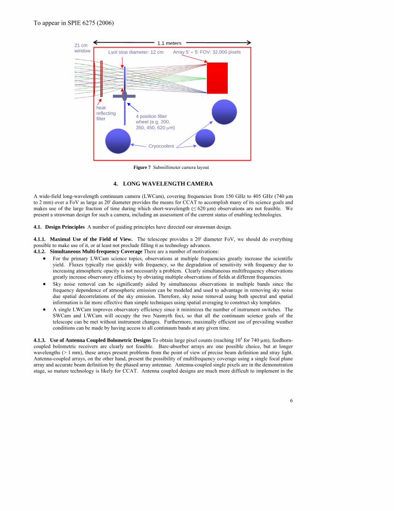
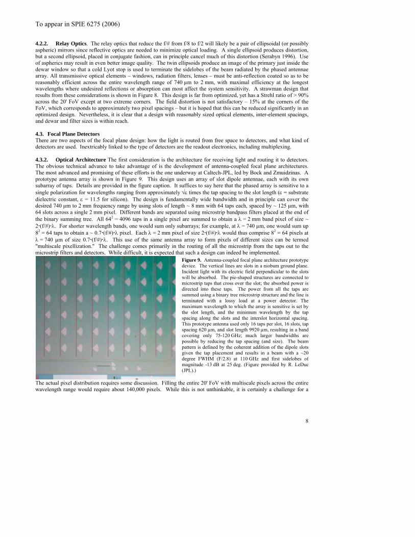
with this system (Figure 5). The spot sizes have an rms radius of less then 0.3 mm (30% of a pixel) even for the most off-axis beams. The image plane is curved, so that the outer pixels can be improved significantly by adjusting the tiling of the focal plane accordingly. One can also do significantly better by letting the lens diameters grow modestly, although this is not deemed necessary. 3requisite optics, filters, electronics, cryocoolers, and array for the submillimeter camera can be enclosed in a cryostat with a diameter of about 0.8 m, and a length of 1.2 m (Figure 7). The beam enters the dewar through the germanium entrance window. Most of the power of the thermal background is reflected back out of the window by and AR coated crystal quartz filter located within 10 cm of the window. This filter needs to be about 20 cm in diameter. The Lyot stop has a diameter of 12 cm, and is formed 21 cm from the entrance window. We place a 4 position filter wheel immediately behind the Lyot stop. This wheel will contain filters for work at 200, 350, 450, and 620 μm (available from the Cardiff University group under the direction of P.A.R. Ade). The image focal plane is 80 cm from the entrance window.
Figure 5. ZEMAX spot diagrams for the optical system outlined in the text. The circles are λ/D in diameter at 350 μm.
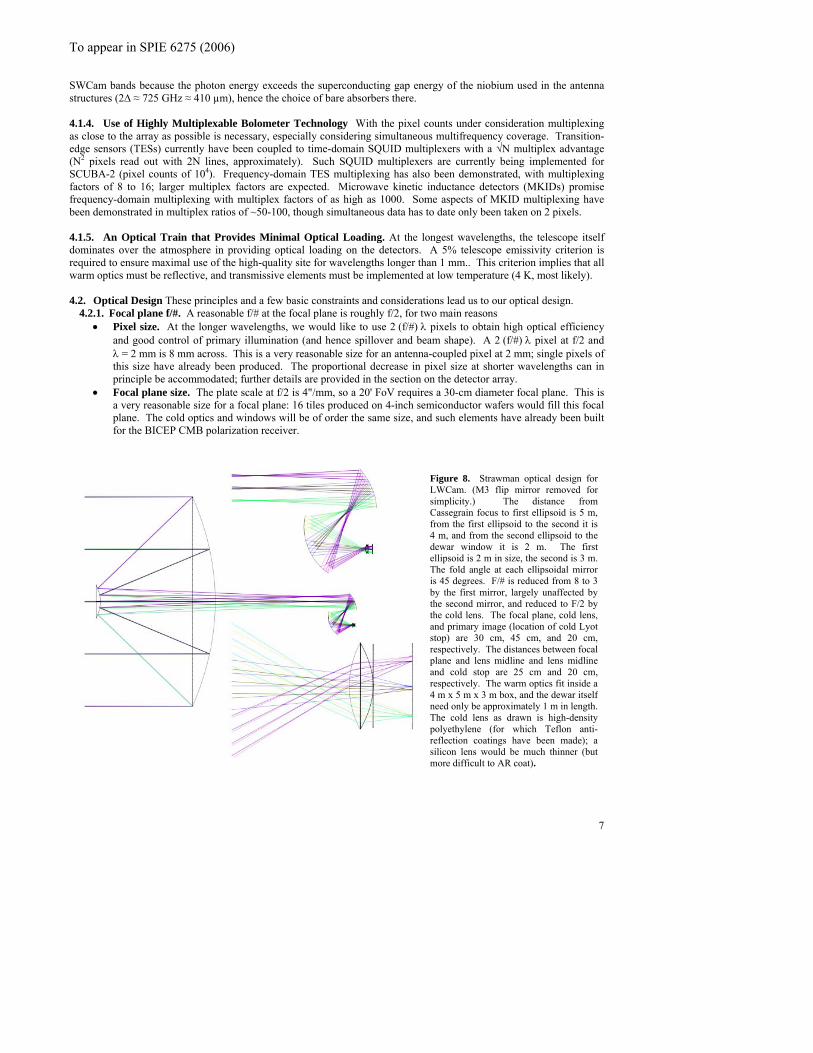
3be procured from NIST (Figure 6). The array consists of 25 edge-butted sub-arrays of 32 × 40 pixel format, or 32,000 pixels. The pixel pitch is the same as for SCUBA-2: 1 mm square. These first of the SCUBA-2 subarrays has been delivered and tested by members of the SCUBA-2 consortium, and they are delivering the expected optical NEPs (Figure 6). These arrays presently deliver the requisite NEPs for the SWCam with a head temperature of 60 mK, and likely deliver the requisite NEPs at
Figure 6. 32 × 40 pixel subarray component of SCUBA-2 array (K. Irwin, personal communication)
ad temperatures o
To appear in SPIE 6275 (2006)
4 position filter wheel (e.g. 200, 350, 450, 620 μm)
21 cm window Array 5’
1.1 meters
× 5’ FOV: 32,000 pixels
Cryocoolers
heat reflecting filter
Lyot stop diameter: 12 cm
6
Figure 7 Submillimeter camera layout
4. LONG WAVELENGTH CAMERA
A wide-field long-wavelength continuum camera (LWCam), covering frequencies from 150 GHz to 405 GHz (740 µm to 2 mm) over a FoV as large as 20' diameter provides the means for CCAT to accomplish many of its science goals and makes use of the large fraction of time during which short-wavelength (≤ 620 µm) observations are not feasible. We present a strawman design for such a camera, including an assessment of the current status of enabling technologies.
4.1. Design Principles A number of guiding principles have directed our strawman design. 4.1.1. Maximal Use of the Field of View. The telescope provides a 20' diameter FoV, we should do everything possible to make use of it, or at least not preclude filling it as technology advances. 4.1.2. Simultaneous Multi-frequency Coverage There are a number of motivations:
• For the primary LWCam science topics, observations at multiple frequencies greatly increase the scientific yield. Fluxes typically rise quickly with frequency, so the degradation of sensitivity with frequency due to increasing atmospheric opacity is not necessarily a problem. Clearly simultaneous multifrequency observations greatly increase observatory efficiency by obviating multiple observations of fields at different frequencies.
• Sky noise removal can be significantly aided by simultaneous observations in multiple bands since the frequency dependence of atmospheric emission can be modeled and used to advantage in removing sky noise due spatial decorrelations of the sky emission. Therefore, sky noise removal using both spectral and spatial information is far more effective than simple techniques using spatial averaging to construct sky templates.
• A single LWCam improves observatory efficiency since it minimizes the number of instrument switches. The SWCam and LWCam will occupy the two Nasmyth foci, so that all the continuum science goals of the telescope can be met without instrument changes. Furthermore, maximally efficient use of prevailing weather conditions can be made by having access to all continuum bands at any given time.
4.1.3. Use of Antenna Coupled Bolometric Designs To obtain large pixel counts (reaching 104 for 740 µm), feedhorn-coupled bolometric receivers are clearly not feasible. Bare-absorber arrays are one possible choice, but at longer wavelengths (> 1 mm), these arrays present problems from the point of view of precise beam definition and stray light. Antenna-coupled arrays, on the other hand, present the possibility of multifrequency coverage using a single focal plane array and accurate beam definition by the phased array antennae. Antenna-coupled single pixels are in the demonstration stage, so mature technology is likely for CCAT. Antenna coupled designs are much more difficult to implement in the
To appear in SPIE 6275 (2006)
SWCam bands because the photon energy exceeds the superconducting gap energy of the niobium used in the antenna structures (2∆ ≈ 725 GHz ≈ 410 µm), hence the choice of bare absorbers there. 4.1.4. Use of Highly Multiplexable Bolometer Technology With the pixel counts under consideration multiplexing as close to the array as possible is necessary, especially considering simultaneous multifrequency coverage. Transition-edge sensors (TESs) currently have been coupled to time-domain SQUID multiplexers with a √N multiplex advantage (N2 pixels read out with 2N lines, approximately). Such SQUID multiplexers are currently being implemented for SCUBA-2 (pixel counts of 104). Frequency-domain TES multiplexing has also been demonstrated, with multiplexing factors of 8 to 16; larger multiplex factors are expected. Microwave kinetic inductance detectors (MKIDs) promise frequency-domain multiplexing with multiplex factors of as high as 1000. Some aspects of MKID multiplexing have been demonstrated in multiplex ratios of ~50-100, though simultaneous data has to date only been taken on 2 pixels. 4.1.5. An Optical Train that Provides Minimal Optical Loading. At the longest wavelengths, the telescope itself dominates over the atmosphere in providing optical loading on the detectors. A 5% telescope emissivity criterion is required to ensure maximal use of the high-quality site for wavelengths longer than 1 mm.. This criterion implies that all warm optics must be reflective, and transmissive elements must be implemented at low temperature (4 K, most likely). 4.2. Optical Design These principles and a few basic constraints and considerations lead us to our optical design.
4.2.1. Focal plane f/#. A reasonable f/# at the focal plane is roughly f/2, for two main reasons • Pixel size. At the longer wavelengths, we would like to use 2 (f/#) λ pixels to obtain high optical efficiency
and good control of primary illumination (and hence spillover and beam shape). A 2 (f/#) λ pixel at f/2 and λ = 2 mm is 8 mm across. This is a very reasonable size for an antenna-coupled pixel at 2 mm; single pixels of this size have already been produced. The proportional decrease in pixel size at shorter wavelengths can in principle be accommodated; further details are provided in the section on the detector array.
• Focal plane size. The plate scale at f/2 is 4"/mm, so a 20' FoV requires a 30-cm diameter focal plane. This is a very reasonable size for a focal plane: 16 tiles produced on 4-inch semiconductor wafers would fill this focal plane. The cold optics and windows will be of order the same size, and such elements have already been built for the BICEP CMB polarization receiver.
Figure 8. Strawman optical design for LWCam. (M3 flip mirror removed for simplicity.) The distance from Cassegrain focus to first ellipsoid is 5 m, from the first ellipsoid to the second it is 4 m, and from the second ellipsoid to the dewar window it is 2 m. The first ellipsoid is 2 m in size, the second is 3 m. The fold angle at each ellipsoidal mirror is 45 degrees. F/# is reduced from 8 to 3 by the first mirror, largely unaffected by the second mirror, and reduced to F/2 by the cold lens. The focal plane, cold lens, and primary image (location of cold Lyot stop) are 30 cm, 45 cm, and 20 cm, respectively. The distances between focal plane and lens midline and lens midline and cold stop are 25 cm and 20 cm, respectively. The warm optics fit inside a 4 m x 5 m x 3 m box, and the dewar itself need only be approximately 1 m in length. The cold lens as drawn is high-density polyethylene (for which Teflon anti-reflection coatings have been made); a silicon lens would be much thinner (but more difficult to AR coat).
7
To appear in SPIE 6275 (2006)
4.2.2. Relay Optics. The relay optics that reduce the f/# from f/8 to f/2 will likely be a pair of ellipsoidal (or possibly aspheric) mirrors since reflective optics are needed to minimize optical loading. A single ellipsoid produces distortion, but a second ellipsoid, placed in conjugate fashion, can in principle cancel much of this distortion (Serabyn 1996). Use of aspherics may result in even better image quality. The twin ellipsoids produce an image of the primary just inside the dewar window so that a cold Lyot stop is used to terminate the sidelobes of the beam radiated by the phased antennae array. All transmissive optical elements – windows, radiation filters, lenses – must be anti-reflection coated so as to be reasonably efficient across the entire wavelength range of 740 µm to 2 mm, with maximal efficiency at the longest wavelengths where undesired reflections or absorption can most affect the system sensitivity. A strawman design that results from these considerations is shown in Figure 8. This design is far from optimized, yet has a Strehl ratio of > 90% across the 20' FoV except at two extreme corners. The field distortion is not satisfactory – 15% at the corners of the FoV, which corresponds to approximately two pixel spacings – but it is hoped that this can be reduced significantly in an optimized design. Nevertheless, it is clear that a design with reasonably sized optical elements, inter-element spacings, and dewar and filter sizes is within reach. 4.3. Focal Plane Detectors There are two aspects of the focal plane design: how the light is routed from free space to detectors, and what kind of detectors are used. Inextricably linked to the type of detectors are the readout electronics, including multiplexing. 4.3.2. Optical Architecture The first consideration is the architecture for receiving light and routing it to detectors. The obvious technical advance to take advantage of is the development of antenna-coupled focal plane architectures. The most advanced and promising of these efforts is the one underway at Caltech-JPL, led by Bock and Zmuidzinas. A prototype antenna array is shown in Figure 9. This design uses an array of slot dipole antennae, each with its own subarray of taps. Details are provided in the figure caption. It suffices to say here that the phased array is sensitive to a single polarization for wavelengths ranging from approximately √ε times the tap spacing to the slot length (ε = substrate dielectric constant, ε = 11.5 for silicon). The design is fundamentally wide bandwidth and in principle can cover the desired 740 µm to 2 mm frequency range by using slots of length ~ 8 mm with 64 taps each, spaced by ~ 125 µm, with 64 slots across a single 2 mm pixel. Different bands are separated using microstrip bandpass filters placed at the end of the binary summing tree. All 642 = 4096 taps in a single pixel are summed to obtain a λ = 2 mm band pixel of size ~ 2 (f/#) λ. For shorter wavelength bands, one would sum only subarrays; for example, at λ = 740 µm, one would sum up 82 = 64 taps to obtain a ~ 0.7 (f/#) λ pixel. Each λ = 2 mm pixel of size 2 (f/#) λ would thus comprise 82 = 64 pixels at λ = 740 µm of size 0.7 (f/#) λ. This use of the same antenna array to form pixels of different sizes can be termed "multiscale pixellization." The challenge comes primarily in the routing of all the microstrip from the taps out to the microstrip filters and detectors. While difficult, it is expected that such a design can indeed be implemented.
Figure 9. Antenna-coupled focal plane architecture prototype device. The vertical lines are slots in a niobum ground plane. Incident light with its electric field perpendicular to the slots will be absorbed. The pie-shaped structures are connected to microstrip taps that cross over the slot; the absorbed power is directed into these taps. The power from all the taps are summed using a binary tree microstrip structure and the line is terminated with a lossy load at a power detector. The maximum wavelength to which the array is sensitive is set by the slot length, and the minimum wavelength by the tap spacing along the slots and the interslot horizontal spacing. This prototype antenna used only 16 taps per slot, 16 slots, tap spacing 620 µm, and slot length 9920 µm, resulting in a band covering only 75-120 GHz; much larger bandwidths are possible by reducing the tap spacing (and size). The beam pattern is defined by the coherent addition of the dipole slots given the tap placement and results in a beam with a ~20 degree FWHM (F/2.8) at 110 GHz and first sidelobes of magnitude -13 dB at 25 deg. (Figure provided by R. LeDuc (JPL).)
The actual pixel distribution requires some discussion. Filling the entire 20' FoV with multiscale pixels across the entire wavelength range would require about 140,000 pixels. While this is not unthinkable, it is certainly a challenge for a
8
To appear in SPIE 6275 (2006)
first-light instrument. The shortest wavelength bands drive this pixel count, and a natural way to reduce the count is to include high-frequency pixels only in the central portion of the array. The FoV is filled with 16 tiles, of which only the central four is populated with multiscale pixels covering up to 405 GHz. This provides a 10' × 10' FoV at 740 µm and 865 µm with 16,384 pixels in each band. The remaining 12 tiles need not, however, totally dispense with the high-frequency bands. Instead, the 740 µm and 865 µm bands would use the same pixel size as 1.1 mm, resulting in only 256 pixels in each band in each tile, or an additional 3072 pixels in each of these bands over the entire array. This provides the benefit of multifrequency sky subtraction to the entire FoV, yet maintains a reasonable detector count: this scheme yields 45,056 detectors summed over all bands. This design may also be sensible if 740 µm optical quality cannot be obtained in the outer parts of the focal plane due to optical aberrations. The pixel count is summarized in Table 1.
9
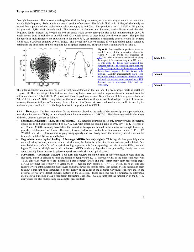
Figure 10. Measured beam profile of antenna-coupled pixel of the architecture shown in Figure 9. The profile was measured at 110 GHz using a coherent source and coupling the output of the antenna array to a SIS mixer.
The antenna-coupled architecture has seen a first demonstration in the lab, and the beam shape meets expectations (Figure 10). The microstrip filters that define observing bands have seen initial implementation in concert with the antenna architecture. The Caltech-JPL group will soon be producing a small 16-pixel array of 4-color pixels – bands at 220, 270, 350, and 420 GHz – using filters of this kind. Wide-bandwidth optics will be developed as part of this effort (covering the entire 740 µm to 2 mm range desired for the CCAT camera). Work will continue in parallel to develop the multiscale pixels needed to cover the large bandwidth range desired for CCAT. 4.3.3. Detectors The best candidates for the detectors placed at the ends of the microstrip are superconducting transition-edge sensors (TESs) or microwave kinetic inductance detectors (MKIDs). The advantages and disadvantages of the two detector types are as follows: • Sensitivity. Advantage: TESs, but only slightly. TES detectors operating at 300 mK already provide sufficiently
good NEP to be background limited on CCAT, even with ambitious loading goals of 10 K sky + 10 K telescope at λ = 2 mm. MKIDs currently have NEPs that would be background limited in the shorter wavelength bands, but probably not longward of 1 mm. This current noise performance is far from fundamental limits (NEP ~ 10-20 W/√Hz), and MKID development is progressing quickly and will likely reach the necessary sensitivities on the timescale that the LWCam would be built.
• Degradation under optical loading. Advantage: MKIDs, but only slightly. TESs degrade less gracefully under optical loading because, above a certain optical power, the device is pushed into its normal state and is blind. One must build in a "safety factor" in optical loading to prevent this from happening. A pair of series TESs, one with higher Tc, can in principle solve this limitation. MKID sensitivity degrades more gracefully, simply due to the approximately linear increase in quiescent quasiparticle density with optical power.
• Fabrication. Advantage: MKIDS Both TESs and MKIDs are simple films of superconductor, though TESs are frequently made in bilayers to tune the transition temperature Tc. Tc reproducibility is the main challenge with TESs, especially when they are incorporated into complex arrays and thus suffer many later processing steps. MKIDs are much less sensitive to variations in Tc because they operate at T << Tc. MKID-based designs also require fewer photolithographic mask layers and hence fewer processing steps. But current MKID designs do seem to show significant noise dependence on the quality of the edges in the coplanar waveguide structure and on the presence of two-level defect impurity systems in the dielectric. These problems may be mitigated by alternative architectures, but could prove a significant fabrication challenge. We also note that the fabrication of the SQUID arrays used for TES multiplexing is a complex process itself.
In both plots, the dashed lines indicated the expected pattern. The missing upper sidelobe in the 2D map is due to limitations in travel during beam mapping; the lobe is not truly missing. Similar measurements have been undertaken using a broadband thermal source and with an antenna array coupled to a TES detectors via a microstrip filter and are consistent.
Deleted:
Deleted:
Deleted:
XX
...
To appear in SPIE 6275 (2006)
10
• Multiplexing. Advantage: MKIDs. There exist demonstrated time-domain and frequency-domain multiplexing schemes for TESs. The multiplexing advantage demonstrated to date are 32 × 40 pixels ⇒ 64 lines for time-domain and multiplex factors of 8 for frequency-domain. The time-domain scheme is rather complex, requiring two stages of SQUID amplifiers, one first-stage SQUID for each array pixel, active (though multiplexed) flux feedback to the first-stage SQUIDs, and FPGA-based room-temperature electronics to control the addressing and feedback to the SQUIDs. The routing of the lines between the array and the first-stage SQUIDs and between the first and second stage SQUIDs is challenging; the former provides no multiplexing advantage and will almost certainly require a custom first-stage SQUID chip that is hybridized with the focal plane array. The frequency-domain scheme requires only a single SQUID array to read out N pixels (N = 8 has been demonstrated), but each pixel must have a custom LC filter placed in-line to isolate its IF band from that of the other pixels. MKIDs, on the other hand, are very easily frequency-multiplexed. A MKID in a notch resonator structure (whose resonant frequency is set by the length of the MKID) is inherently narrowband. A set of MKIDs can be attached to a single feed line without interacting with each other. Room temperature electronics can be used to construct a frequency comb to bias the resonators; that bias is sent down the single feed line. A HEMT at the output of the feedline amplifies the transmitted signal, which can then be frequency-demultiplexed at room temperature. Emergent software-defined radio techniques promise to make bias generation and demultiplexing almost entirely digital and buildable using commercial electronics. A multiplex advantage of 103 is entirely feasible.
• Cold electronics power dissipation: Advantange: TESs. In the time-domain SQUID multiplexing scheme, the first-stage single-SQUID chips dissipate about 2 nW per detector pixel. Using 3He closed-cycle refrigeration, this becomes challenging at the 10,000 pixel level, but Kent Irwin (NIST) has indicated first-stage SQUID power dissipation could be reduced significantly (especially because large detector response bandwidth is not necessary for bolometric cameras). The SQUID arrays that reside at 4 K dissipate about 1 µW each, but only one array is needed per "column" in this multiplexing scheme, currently 40 pixels. Even at 40,000 pixels, one only dissipates 1 mW at 4 K, which is quite reasonable. In the frequency-domain scheme, no first-stage SQUIDs are used, and the SQUID arrays again sit at 4 K. The multiplex factor may be somewhat lower (N = 8 has been demonstrated), but the 4 K load remains small. MKID readout power dissipation is significantly larger because of the use of HEMTs. These reside at 4 K and dissipate 10-20 mW each there. The power dissipation could thus approach 1 W for a 50,000 pixel array. However, Sandy Weinreb (JPL) indicates that HEMTs with sufficiently good noise temperatures could be obtained at 10 to 100 times smaller power dissipation, reducing the heat load to a level that is small compared to quiescent loads on 4 K.
• Microphonic Susceptibility: Advantage: MKIDs. Because cryocoolers are being baselined for all CCAT instruments, sensitivity to vibrations are an important consideration. MKIDs offer an important advantage here: because they are non-thermal detectors, they are rather insensitive to thermal fluctuations in the refrigerator base temperature stage. The gap energy in aluminum, for example, corresponds to 4 K. Vibrations reaching the base temperature stage must be made much less than this typical energy in order for the refrigeration itself to function, so it is very unlikely that vibrations will be so large as to break Cooper pairs. It should be noted that the operation of TES bolometers with cryocoolers has been demonstrated, in particular APEX-SZ and SCUBA-2. It is certainly possible to implement TESs from a cryocooler platform, it just requires additional engineering care.
Antenna-coupled TES and MKID receivers are being prototyped by the Caltech-JPL group: proposals have been submitted for SPIDER, a balloon-borne CMB polarization receiver that will use dual-polarization, single-color focal planes in bands from 40 GHz to 275 GHz, and for a MKID-based multicolor camera for the CSO. These projects, if successful, will leave only two specific technology challenges for CCAT: multiscale antenna-coupled pixel design and very wide-bandwidth optics. This is an acceptable level of technical risk.
5. POLARIMETRY
Measurement of linear polarization in the submillimeter allows the study of magnetic fields in interstellar clouds and active galactic nuclei. A common characteristic of successful polarimeters operating at (sub)millimeter wavelengths in the presence of the bright and variable atmosphere is their ability to reject unpolarized emission on short timescales (>1 Hz). This has been done with chopping secondary mirrors (SCUBA6), simultaneous dual-polarization imaging of the field of view (e.g. SHARP7), both of those (e.g. Hertz8), or rapid polarization modulation (e.g. POLKA9).

To appear in SPIE 6275 (2006)
11
For first-light CCAT polarimetry, we will adopt the rapid polarization modulation approach due to its cost effectiveness and the expected <<1% instrumental polarization of the telescope, despite the √2 sensitivity penalty compared to dual-polarization imaging. The baseline plan will be a constantly rotating quartz half-wave plate – which can be warm without significant noise penalty – followed by a wire polarizer at the window of SWCam and LWCam. The newer Martin-Puplett polarization modulation concept10 is another option for implementation in reflective relay optics. More options are available for second-generation CCAT polarimetry. Some promising detector architectures have dual-polarization sensing, and polarization-splitting foreoptics could be built to feed multi-array cameras. Both of these approaches will recover the full polarization sensitivity available with CCAT.
6. BORROWED INSTRUMENTATION
The camera described above will deliver the fundamental science goals of the project. However, it is clear that the science can be enhanced through the addition of other capabilities such as submillimeter spectroscopy both with direct detection and heterodyne receivers. Members of the consortia have constructed a wide variety of such instrumentation for both the JCMT and CSO telescopes. These instruments continue to evolve and be replaced by better instruments as technological improvements are attained. For modest resolving powers, direct detection spectrometers are the instruments of choice since they can have very large instantaneous bandwidths and operate near the photon noise limit. Currently, there are two direct detection spectrometers and a variety of heterodyne receivers in use on the CSO that are of great interest to CCAT: (1) ZEUS The redshift (Z) and Early Universe Spectrometer (ZEUS) is an echelle grating spectrometer capable of operating in the 200 to 850 μm regime11. ZEUS has a resolving, R≡Δλ/λ ~ 1000, and moderate (~ 3 to 6%) spectral bandwidth, well suited for detecting lines from distant galaxies. ZEUS on CCAT could detect starburst and ultraluminous galaxies with far-IR luminosities of about 2 × 10¹¹ L at redshifts beyond 5 in their redshifted [CII] 158 μm line emission. This line and the far-IR continuum constrain the physical size, and intensity of the starburst. ZEUS can be operated as a long slit echelle, with up to a dozen spatial samples, or (with light pipes) distinct sources on the sky. (2) Z-Spec The Z-Spec spectrometer presents an alternative to conventional long-slit grating instruments. It uses a new architecture consisting of a curved grating inside parallel plate waveguide to provide nearly an octave of instantaneous bandwidth in a small size12,13. The light from a single spatial mode propagates through the waveguide region to the curved grating which both focuses and diffracts the light to an array of detectors resulting in a very compact configuration. Z-Spec operates from 1 to 1.6 mm wave regime with a resolving power of a few hundred and is optimized for detecting redshifted CO lines from distant galaxies. The large bandwidth of Z-Spec ensures simultaneous detection of two CO lines from which the redshift of the source may be determined. Z-Spec is readily stackable for up to a dozen spatial samples, or (with light pipes) distinct sources on the sky. (3) Heterodyne Receivers. Heterodyne receivers currently on the CSO enable access to all of the submillimeter windows (except 200 μm). These receivers have excellent sensitivity – typically within a factor of 5 of the quantum limit. These are the receivers of choice for high resolution spectroscopy, such as is required for detailed investigations of Galactic star formation regions. Very sensitive HEB terahertz devices exist and have been used in receivers at the South Pole and Atacama sites with good success14. The receivers are compact and easily transportable to the CCAT facility. Near future developments promise multi-pixel arrays at all frequencies.
7. UPGRADE PATHS
There are natural upgrade paths for both the SWCam and LWCam. The SWCam design utilizes lenses, that can deliver the requisite image quality over the 5’×5’FoV of the camera. To access the full 20’×20’ FoV of CCAT with a single lens system would result in poor optical transmission, however. A far simpler upgrade path is to make several copies of the current SWCam including the fore-optics. These multiple cameras can be nestled in a close-packed configuration to give good coverage of the 20’ FoV. The total coverage of the 4 cameras would be 102 square arcminutes, or 1/3 of the total area in the 20” diameter FoV. For LWCam, the natural upgrade path is to cover entire FoV with ~ Nyquist-sampled
To appear in SPIE 6275 (2006)
pixels at 740, and 865 µm, resulting in a total of 137,216 pixels. To additionally cover the entire FoV with ~Nyquist-sampled pixels at 620 µm, adding 262,144 pixels in addition to the 137,216 pixels in the first upgrade.
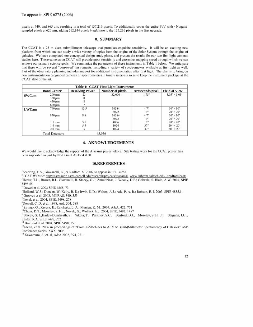
8. SUMMARY
The CCAT is a 25 m class submillimeter telescope that promises exquisite sensitivity. It will be an exciting new platform from which one can study a wide variety of topics from the origins of the Solar System through the origins of galaxies. We have completed our conceptual design study phase, and present the results for our two first light cameras studies here. These cameras on CCAT will provide great sensitivity and enormous mapping speed through which we can achieve our primary science goals. We summarize the parameters of these instruments in Table 1 below. We anticipate that there will be several “borrowed” instruments, including a variety of spectrometers available at first light as well. Part of the observatory planning includes support for additional instrumentation after first light. The plan is to bring on new instrumentation (upgraded cameras or spectrometers) in timely intervals so as to keep the instrument package at the CCAT state of the art.
Table 1: CCAT First Light Instruments Band Center Resolving Power Number of pixels Arcseconds/pixel Field of View SWCam 200 μm
350 μm 450 μm 620 μm
23 8 8 7
32,000 1.75″ 5.05′ × 5.05′
740 μm
870 μm
1.1 mm 1.4 mm
2.0 mm
13.5
8.8
5.5 5.5 5
16384 3072 16384 3072 4096 1024 1024
4.7″ 19″ 4.7″ 19″ 19″ 37″ 37″
10′ × 10′ 20′ × 20′ 10′ × 10′ 20′ × 20′ 20′ × 20′ 20′ × 20′ 20′ × 20′
LWCam
Total Detectors 45,056
9. AKNOWLEDGEMENTS
We would like to acknowledge the support of the Atacama project office. Site testing work for the CCAT project has been supported in part by NSF Grant AST-043150.
10. REFERENCES
1Seebring, T.A., Giovanelli, G., & Radford, S. 2006, to appear in SPIE 6267 2CCAT Website: http://astrosun2.astro.cornell.edu/research/projects/atacama/, www.submm.caltech.edu/~sradford/ccat/3Herter, T.L., Brown, R.L. Giovanelli, R. Stacey, G.J.; Zmuidzinas, J. Woody, D.P.; Golwala, S. Blain, A.W. 2004, SPIE 5498 55 4 Dowel et al. 2003 SPIE 4855, 73 5Holland, W S.; Duncan, W; Kelly, B. D.; Irwin, K D.; Walton, A.J.; Ade, P. A. R.; Robson, E. I. 2003, SPIE 4855,1. 6 Greaves et al. 2003, MNRAS, 340, 353 7Novak et al. 2004, SPIE, 5498, 278 8Dowell, C. D. et al. 1998, ApJ, 504, 588 9 Siringo, G.; Kreysa, E.; Reichertz, L. A.; Menten, K. M.. 2004, A&A, 422, 751 10Chuss, D.T.; Moseley, S. H.,., Novak, G.; Wollack, E.J. 2004, SPIE, 5492, 1487 11Stacey, G. J.,Hailey-Dunsheath, S. Nikola, T, Parshley, S.C., Benford, D.J., Moseley, S. H., Jr.; Staguhn, J.G.., Shafer, R.A. SPIE 5498, 232 12 Bradford et al. 2004, SPIE 5498, 257 13Glenn, et al. 2006 in proceedings of “From Z-Machines to ALMA: (Sub)Millimeter Spectroscopy of Galaxies” ASP Conference Series, XXX, 2006 14 Kawamura, J.; et. al, A&A 2002, 394, 271.
12