Embed Size (px)
Citation preview
8/12/2019 IV 02 Future Automatic Transmission Requirements Submission VDI Transmission
http://slidepdf.com/reader/full/iv-02-future-automatic-transmission-requirements-submission-vdi-transmission 1/8
Future Automatic Transmission Requirements
P. Janssen MSc, FEV Motorentechnik Aachen.K. Govindswamy Phd, FEV Inc. Auburn Hills.
Kurzfassung
Bisher wurde der spezifische Leistungszuwachs(downsizing) der Motoren im Fahrzeug verwendetfür Leistungssteigerung und zum kompensierendes Gewichtes. Zukünftig weiteres downsizingmehr und mehr genutzt zurVerbrauchsreduzierung. Um dieVerbrauchspotentiale auszunutzen und dieFahrzeuge insbesondre im Anfahrbereich fahrbarzu halten wird eine Drehmomentspreizung bis zu
10 und Anfahrübersetzungen kleiner 20(Drehmomentübersetzung) notwendig.Die konventionelle Wandlerautomaten sind heutemit 8 Gänge und Drehmomentverstärkung durchden Wandler schon fast im Zielbereich.Bei DKG Getriebe werden völlig neueRadsatzstrukturen notwendig um mit vertretbaremmechanischem Aufwand dieSpreizungsanforderung gerecht zu werden.Mit dem X-DCT zeigt FEV ein solchesGetriebekonzept. Das Getriebe hat einemechanische Komplexität vergleichbar mit einem6 oder 7-Gang DKG und realisiert damit 10Vorwärtsgänge mit einer Spreizung von 10,3.
Abstract (optional)
So far engine downsizing in passenger cars hasbeen used to increase the vehicle performanceand to compensate the vehicle weight increase. Inthe future the continuing downsizing trend on theengine side will be used to maintain today’sperformance level and further reduce the fuelconsumption. To maintain launch performanceand at the same time exploit the engine potential a(torque) ratio spread of up to 10 and launch ratioof up to 20 will be necessary. The future automatictransmission will be the enabler to exploit the
potential of these extreme downsized vehicles.Today’s planetary automatic transmissions with upto 8 gears and torque amplification during launch(converter) are already close to this target.For DCT transmissions new gear set approacheswill become necessary to realize the demandedratio spread with acceptable mechanicalcomplexity.With the X-DCT FEV shows such a DCTtransmission concept. The X-DCT has 10 forwardgears and a ratio spread of about 10.3 with a
mechanical complexity comparable to aconventional 6 or 7 speed DCT.
Introduction
Transmission development has seen a revolutionin technology over the last decade. The markethas witnessed a large diversification in technologywith automatic transmissions (AT), continuously
variable transmissions (CVT), automated manualtransmissions (AMT), dual clutch transmissions(DCT) and last but not least hybrid transmissions.The number of gears has been steadily increasingfrom 4, 5 up to 8 and more gears. Where does itstop? Are these gears sill useful or not? Thispaper will from address these questions from atechnical point of view. By looking at futureengine and vehicle trends, technologyrequirements for future transmissions can begenerated. Finally some solution scenarios will bepresented.
Engine Technology
Specific power and torque output of engines hasbeen continuously increasing over time. However,naturally aspirated engines are physicallyrestricted in torque capacity by ambient airpressure. They have come to saturation at about100 Nm/l displacement (gasoline engines).Further power increase will either cause increasein swept volume or boosting. Boosted Dieselengines have been in common use for manyyears. Demands for increase in power andreduction in fuel consumption have also resultedin application of boosting technologies to gasolineengines. In the near future it is expected that this
so called downsizing will continue, mainly drivenby fuel economy requirements.
Gasoline engines with specific power of up to 100kW/l and torque levels up to 200 Nm/l (PME up to25 bar) and diesel engines with specific power ofup to 80 kW/l and torque levels up to 220 Nm/l(PME up to 28 bar) are currently underdevelopment. Figure 1 shows an expectedroadmap for specific power and specific torquetrends of gasoline engines.

8/12/2019 IV 02 Future Automatic Transmission Requirements Submission VDI Transmission
http://slidepdf.com/reader/full/iv-02-future-automatic-transmission-requirements-submission-vdi-transmission 2/8
50
100
150
200
250
1990 1995 2000 2005 2010 2015
Model Year [-]
S p e c i f i c T o r q u e [ N m / l ]
20
40
60
80
100
120
S p e c i f i c P o w e r
[ k W / l ]
FEV
Scatterband
FEV
Scatterband
NA engines
Boosted engines
NA engines
Boosted engines
High Power
High Power
50
100
150
200
250
1990 1995 2000 2005 2010 2015
Model Year [-]
S p e c i f i c T o r q u e [ N m / l ]
20
40
60
80
100
120
S p e c i f i c P o w e r
[ k W / l ]
FEV
Scatterband
FEV
Scatterband
NA engines
Boosted engines
NA engines
Boosted engines
High Power
High Power
20
40
60
80
100
120
S p e c i f i c P o w e r
[ k W / l ]
FEV
Scatterband
FEV
Scatterband
NA engines
Boosted engines
NA engines
Boosted engines
High Power
High Power
FEV
Scatterband
FEV
Scatterband
NA engines
Boosted engines
NA engines
Boosted engines
High Power
High Power
Figure 1: Roadmap full load performance gasolineengines
Vehicle Level Analysis
Passenger cars have seen a continuous increasein vehicle weight, mainly driven by increasedsafety and technology demands. At the same timethe performance level also increased. Airresistance shows a slow decreasing trend, butdoes not play a major role for this analysis. Ananalysis of the vehicle fleet in Germany clearlyshows this trend. From 2000 to 2009 the averagevehicle weight increased by 11%. At the sametime the vehicle performance increased. Botheffects together caused an engine power increase
of around 50%.Although engines have been steadily increased inspecific power (downsizing) they were not able tomeet the power requirements without increasingswept volume. The statistics show an increase inengine swept volume of up to 30% for gasolineengines over the last decade, despite an increasein specific engine power.
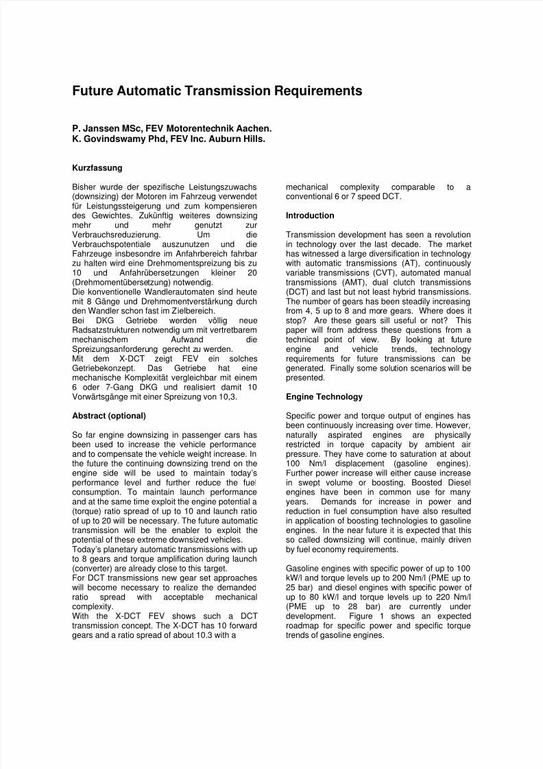
In other words: engine downsizing was so far notused for actual downsizing on vehicle level, butwas overcompensated by weight and performanceincrease. Figure 2 shows an analysis of thegasoline vehicle fleet in Germany [1]
Driven by the recent CO2 awareness the vehicledriving resistance will remain nearly constant inthe near future. For the same reasons and thevery high performance levels already achievedtoday also they will remain nearly constant in the
near future. By combining the data of the engineroadmap with the vehicle fleet data it becomesclear that in the near future the downsizing effectwill no longer be overcompensated by increasedvehicle demands.In other words, “real downsizing” on vehicle level,i.e., decreasing the swept volume to vehicleweight ratio, has only just begun.
8/12/2019 IV 02 Future Automatic Transmission Requirements Submission VDI Transmission
http://slidepdf.com/reader/full/iv-02-future-automatic-transmission-requirements-submission-vdi-transmission 3/8
Figure 2: Gasoline vehicle fleet characteristics onGerman market
Impact on transmission system
The motivations for buying a vehicle have movedaway from powertrain specifications to otherfeatures like image, comfort and accessories. Thismeans that the driver does not specifically ask fora 6 or 8 speed transmission. This however, does
not mean that the expectations on the vehicles’driveability have changed.
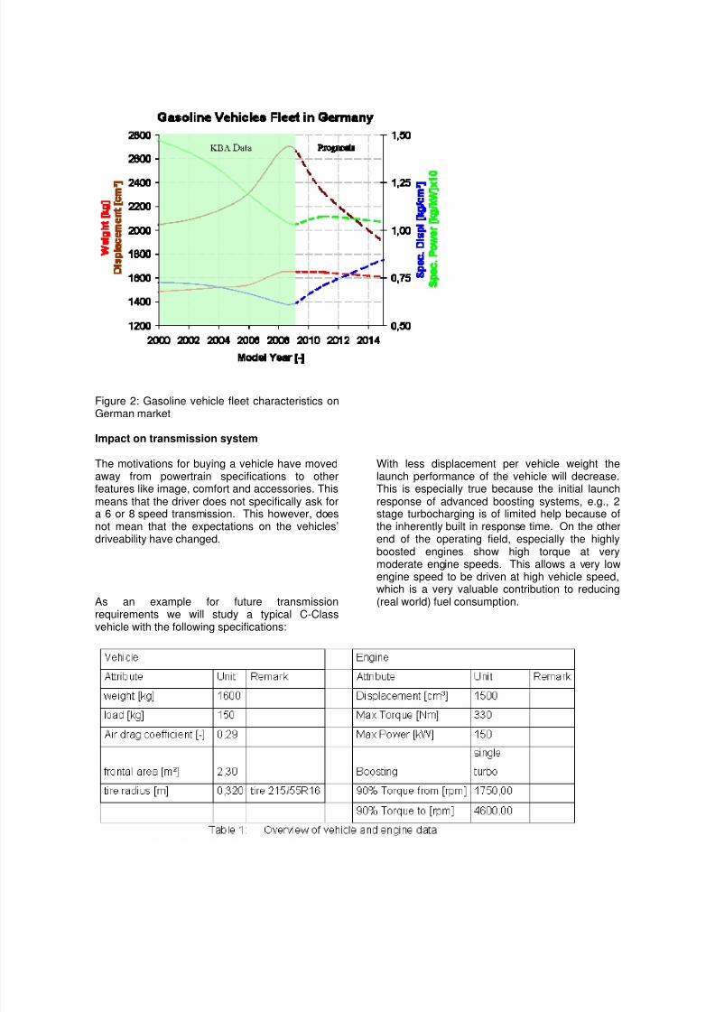
As an example for future transmissionrequirements we will study a typical C-Classvehicle with the following specifications:
With less displacement per vehicle weight thelaunch performance of the vehicle will decrease.This is especially true because the initial launchresponse of advanced boosting systems, e.g., 2stage turbocharging is of limited help because of
the inherently built in response time. On the otherend of the operating field, especially the highlyboosted engines show high torque at verymoderate engine speeds. This allows a very lowengine speed to be driven at high vehicle speed,which is a very valuable contribution to reducing(real world) fuel consumption.
8/12/2019 IV 02 Future Automatic Transmission Requirements Submission VDI Transmission
http://slidepdf.com/reader/full/iv-02-future-automatic-transmission-requirements-submission-vdi-transmission 4/8
First gear ratio requirement
In the first gear the vehicle must be able to launchunder all circumstances, e.g., trailer towing oruphill driving without overheating or breaking
down. In addition, the vehicle must be able tolaunch with acceptable performance and havereasonable engine speeds during low speeddriving (especially manual transmissions).Today, the first gear ratio is mainly defined bylaunch behaviour and not by “classical” items suchas clutch heat capacity.
To define and objectify launch behavior thefollowing attributes can be used:
Response time until vehicle noticeably startsmoving (initial response)
Time from pedal start until 1 m/s² vehicle
acceleration has been achieved Steep yet comfortable acceleration increase Minimum acceleration gradient to be achieved
from initial response to 80% of maxacceleration, but limited to 4 m/s²
Maximum Jerkiness, e.g., VDV < 0,20measured with FEV os
High maximum acceleration Achieve peak 75% of maximum acceleration or
wheel slip limit within first second
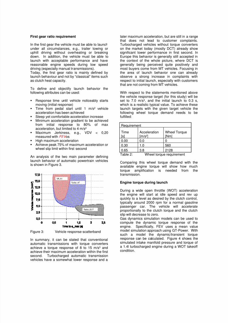
An analysis of the two main parameter defininglaunch behavior of automatic powertrain vehiclesis shown in Figure 3.
Figure 3: Vehicle response scatterband
In summary, it can be stated that conventionalautomatic transmissions with torque convertersachieve a torque response of 8 to 15 m/s³ andachieve their maximum acceleration within the firstsecond. Turbocharged automatic transmissionvehicles have a somewhat lower response and a
later maximum acceleration, but are still in a rangethat does not lead to customer complaints.Turbocharged vehicles without torque converterson the market today (mostly DCT) already showsignificant lower performance in first second. In
Europe this behavior is generally still accepted inthe context of the whole picture, where DCT isgenerally being perceived quite positively andmost buyers come from MT vehicles. Focusing inthe area of launch behavior one can alreadyobserve a strong increase in complaints withrespect to initial launch, especially with customersthat are not coming from MT vehicles.
With respect to the statements mentioned abovethe vehicle response target (for this study) will beset to 7.0 m/s³, and the initial launch to 0.3 s,which is a realistic typical value. To achieve theselaunch targets with the given target vehicle the
following wheel torque demand needs to befulfilled:
Requirement
Time[s]
Acceleration[m/s²]
Wheel Torque[Nm]
0.00 0.0 0
0.30 1.0 560
0.65 3.8 2128Table 2: Wheel torque requirement
Comparing this wheel torque demand with theavailable engine torque will show how much
torque amplification is needed from thetransmission.
Engine torque during launch
During a wide open throttle (WOT) accelerationthe engine will start at idle speed and rev upquickly to a level as desired by the clutch control,typically around 2000 rpm for a normal gasolinepassenger car. The vehicle will accelerateproportionally to the clutch torque and the clutchslip will decrease to zero.Gas dynamics simulation models can be used tocompute the dynamic torque response of the
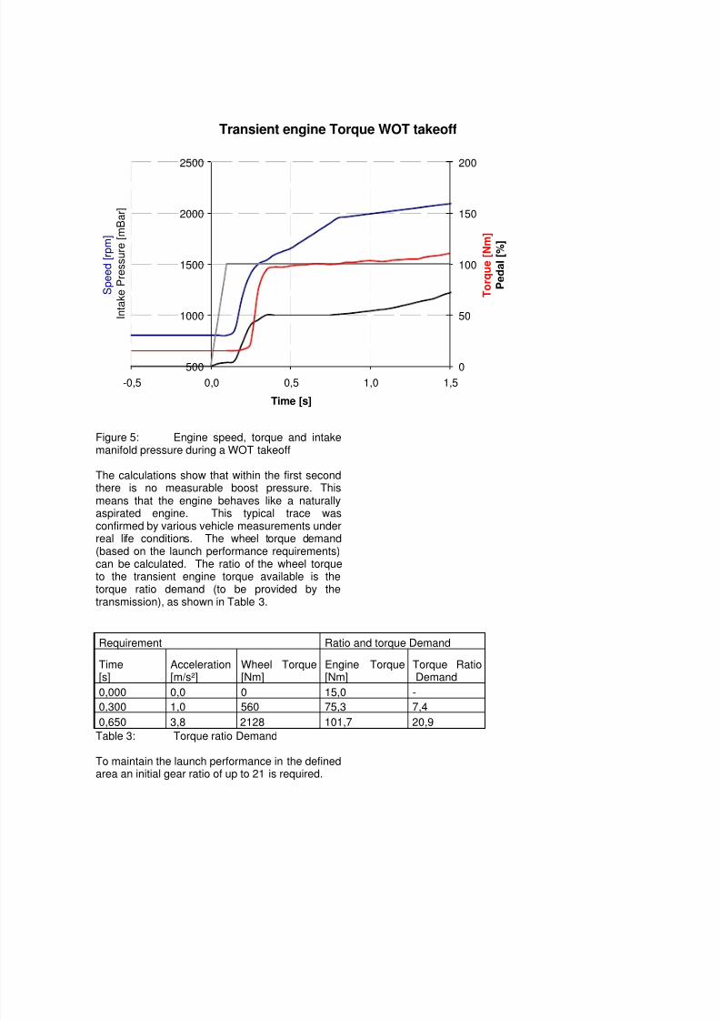
engine. Specifically, FEV uses a mean valuemodel simulation approach using GT-Power. Withsuch a model the dynamic/transient torqueresponse can be calculated. Figure 4 shows thesimulated intake manifold pressure and torque ofa 1.4l turbocharged engine during a WOT takeoffcondition.
8/12/2019 IV 02 Future Automatic Transmission Requirements Submission VDI Transmission
http://slidepdf.com/reader/full/iv-02-future-automatic-transmission-requirements-submission-vdi-transmission 5/8
Transient engine Torque WOT takeoff
500
1000
1500
2000
2500
-0,5 0,0 0,5 1,0 1,5
Time [s]
S p e e d [ r p m ]
I n t a k e P r e s s u r e [ m B a r ]
0
50
100
150
200
T o r q u e [ N m ]
P e d a l [ % ]
Figure 5: Engine speed, torque and intakemanifold pressure during a WOT takeoff
The calculations show that within the first secondthere is no measurable boost pressure. Thismeans that the engine behaves like a naturallyaspirated engine. This typical trace wasconfirmed by various vehicle measurements under
real life conditions. The wheel torque demand(based on the launch performance requirements)can be calculated. The ratio of the wheel torqueto the transient engine torque available is thetorque ratio demand (to be provided by thetransmission), as shown in Table 3.
Requirement Ratio and torque Demand
Time[s]
Acceleration[m/s²]
Wheel Torque[Nm]
Engine Torque[Nm]
Torque RatioDemand
0,000 0,0 0 15,0 -
0,300 1,0 560 75,3 7,4
0,650 3,8 2128 101,7 20,9
Table 3: Torque ratio Demand
To maintain the launch performance in the definedarea an initial gear ratio of up to 21 is required.
8/12/2019 IV 02 Future Automatic Transmission Requirements Submission VDI Transmission
http://slidepdf.com/reader/full/iv-02-future-automatic-transmission-requirements-submission-vdi-transmission 6/8
Last gear ratio
From a fuel economy point of view the enginespeed should always be as low as possible.Hence, the WOT power available from the engine
is fully utilized to propel the vehicle at the desiredspeed.From a driveability point of view a certain reservetorque in gear is needed to ensure driveability.From the customers’ point of view it would not belogical to have a last gear that can only be usedabove the daily and/or allowed speed limit.
To define and objectify this behavior in numbersthe last gear ratio should be able to fulfill:
Top gear must be useable in daily life: At moderate highway speeds, the vehicle
must be able to climb slight grades that cannot be detected by the driver.
Requirement: Being able to drive 140 km/hat 4% grade in top gear
Provide a sufficient acceleration reserve atnormal cruising speeds
Requirement: Being able to drive 90 km/h intop gear with a minimum accelerationreserve of 0.5 m/s² (or 6.5% uphill)
Top gear must be useable in test cycle Being able to drive top gear from 100 km/h Being able to accelerate from 100 to 120
km/h in NEDC cycle in top gear Requirement: Being able to accelerate from
100 to 120 km/h with a minimum gradient of1 km/h/s (equals 0.28 m/s² or 3.6% uphill)
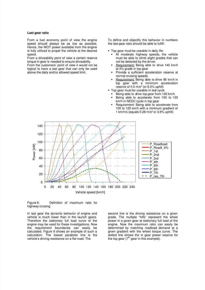
Figure 6: Definition of maximum ratio forhighway cruising
In last gear the dynamic behavior of engine andvehicle is much lower than in the launch gears.Therefore the stationary full load curve of theengine may be used for these investigations. Nowthe requirement boundaries can easily becalculated. Figure 6 shows an example of such acalculation. The lowest parabolic line is thevehicle’s driving resistance on a flat road. The
second line is the driving resistance on a givengrade. The multiple “hills” represent the wheelpower in a given gear at stationary full load of theengine. Now the maximum ratio can easily bedetermined by matching roadload demand at agiven gradient with the wheel torque curve. Thedotted line shows the in gear power reserve forthe top gear (7
th gear in this example).
0
20
40
60
80
100
120
140
0 20 40 60 80 100 120 140 160 180 200 220 240
Vehicle speed [km/h]
P o w e r [ k W ] P_Roadload
P_Roadl_4%
P_1stP_2ndP_3rdP_4thP_5thP_6thP_7thP_res_7th
8/12/2019 IV 02 Future Automatic Transmission Requirements Submission VDI Transmission
http://slidepdf.com/reader/full/iv-02-future-automatic-transmission-requirements-submission-vdi-transmission 7/8
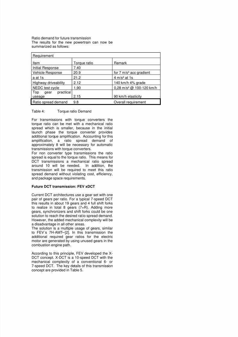
Ratio demand for future transmissionThe results for the new powertrain can now besummarized as follows:
Requirement
Item Torque ratio Remark
Initial Response 7.40
Vehicle Response 20.9 for 7 m/s³ acc gradient
a at 1s 21.2 4 m/s² at 1s
Highway driveability 2.12 140 km/h 4% grade
NEDC test cycle 1,90 0,28 m/s² @ 100-120 km/hTop gear practicaluseage 2.15 90 km/h elasticity
Ratio spread demand 9.8 Overall requirement
Table 4: Torque ratio Demand
For transmissions with torque converters thetorque ratio can be met with a mechanical ratiospread which is smaller, because in the initiallaunch phase the torque converter providesadditional torque amplification. Accounting for thisamplification, a ratio spread demand ofapproximately 8 will be necessary for automatictransmissions with torque converters.For non converter type transmissions the ratiospread is equal to the torque ratio. This means forDCT transmissions a mechanical ratio spreadaround 10 will be needed. In addition, thetransmission will be required to meet this ratiospread demand without violating cost, efficiency,
and package space requirements.
Future DCT transmission: FEV xDCT
Current DCT architectures use a gear set with onepair of gears per ratio. For a typical 7-speed DCTthis results in about 19 gears and 4 full shift forksto realize in total 8 gears (7+R). Adding moregears, synchronizers and shift forks could be onesolution to reach the desired ratio spread demand.However, the added mechanical complexity will bea disadvantage in all other areas.The solution is a multiple usage of gears, similarto FEV´s 7H-AMT [2]. In this transmission the
additional required gear ratios for the electricmotor are generated by using unused gears in thecombustion engine path.
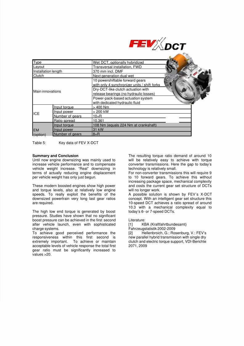
According to this principle, FEV developed the X-DCT concept. X-DCT is a 10-speed DCT with themechanical complexity of a conventional 6- or7-speed DCT. The key details of this transmissionconcept are provided in Table 5.
8/12/2019 IV 02 Future Automatic Transmission Requirements Submission VDI Transmission
http://slidepdf.com/reader/full/iv-02-future-automatic-transmission-requirements-submission-vdi-transmission 8/8
Wet DCT, optionally hybridized
Transversal installation, FWD
370 mm incl. DMF
Next generation dual wet
10 powershiftable forward gears
with only 4 synchronizer units / shift forks
Dry-DCT-like clutch actuation with
release bearings (no hydraulic losses)
Power-pack-based actuation system
with dedicated hydraulic fluid
Input torque > 400 Nm
Input power > 200 kW
Number of gears 10+R
Ratio spread 10.361Input torque 108 Nm (equals 224 Nm at crankshaft)
Input power 31 kW
Number of gears 8+R
ICE
EM
(option)
Type
Layout
Installation length
Clutch
Main innovations
Table 5: Key data of FEV X-DCT
Summary and ConclusionUntil now engine downsizing was mainly used toincrease vehicle performance and to compensatevehicle weight increase. “Real” downsizing interms of actually reducing engine displacementper vehicle weight has only just begun.
These modern boosted engines show high powerand torque levels, also at relatively low enginespeeds. To really exploit the benefits of thedownsized powertrain very long last gear ratiosare required.
The high low end torque is generated by boostpressure. Studies have shown that no significantboost pressure can be achieved in the first secondafter vehicle launch, even with sophisticatedcharge systems.To achieve good perceived performance theresponsiveness within this first second is
extremely important. To achieve or maintainacceptable levels of vehicle response the total firstgear ratio must be significantly increased tovalues >20.
The resulting torque ratio demand of around 10will be relatively easy to achieve with torqueconverter transmissions. Here the gap to today’stechnology is relatively small.For non-converter transmissions this will require 9to 10 forward gears. To achieve this without
increasing package space, mechanical complexityand costs the current gear set structure of DCTswill no longer work.A possible solution is shown by FEV´s X-DCTconcept. With an intelligent gear set structure this10-speed DCT achieves a ratio spread of around10.3 with a mechanical complexity equal totoday’s 6- or 7-speed DCTs.
Literature:[1] KBA (Kraftfahrtbundesamt)Fahrzeugstatistik 2002-2009[2] Hellenbroich, G.; Rosenburg, V.: FEV’snew parallel hybrid transmission with single dry
clutch and electric torque support, VDI-Berichte2071, 2009