Embed Size (px)
Citation preview
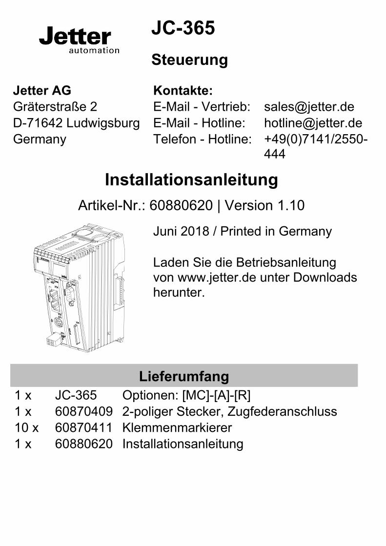
JC-365 Steuerung
Jetter AG Kontakte: Gräterstraße 2 E-Mail - Vertrieb: [email protected] D-71642 Ludwigsburg E-Mail - Hotline: [email protected] Germany Telefon - Hotline: +49(0)7141/2550-
444
Installationsanleitung Artikel-Nr.: 60880620 | Version 1.10
Juni 2018 / Printed in Germany Laden Sie die Betriebsanleitung von www.jetter.de unter Downloads herunter.
Lieferumfang 1 x JC-365 Optionen: [MC]-[A]-[R] 1 x 60870409 2-poliger Stecker, Zugfederanschluss 10 x 60870411 Klemmenmarkierer 1 x 60880620 Installationsanleitung
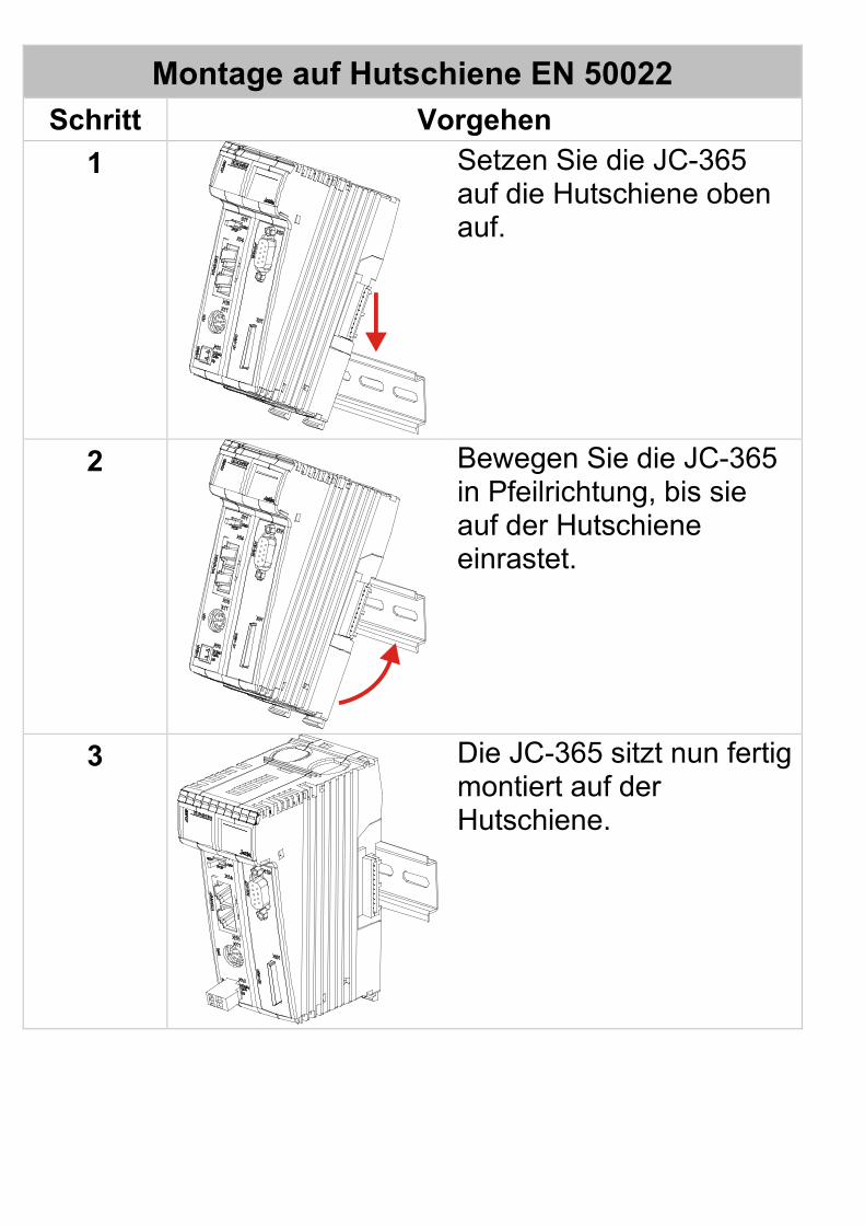
Montage auf Hutschiene EN 50022 Schritt Vorgehen
1
Setzen Sie die JC-365 auf die Hutschiene oben auf.
2
Bewegen Sie die JC-365 in Pfeilrichtung, bis sie auf der Hutschiene einrastet.
3
Die JC-365 sitzt nun fertig montiert auf der Hutschiene.
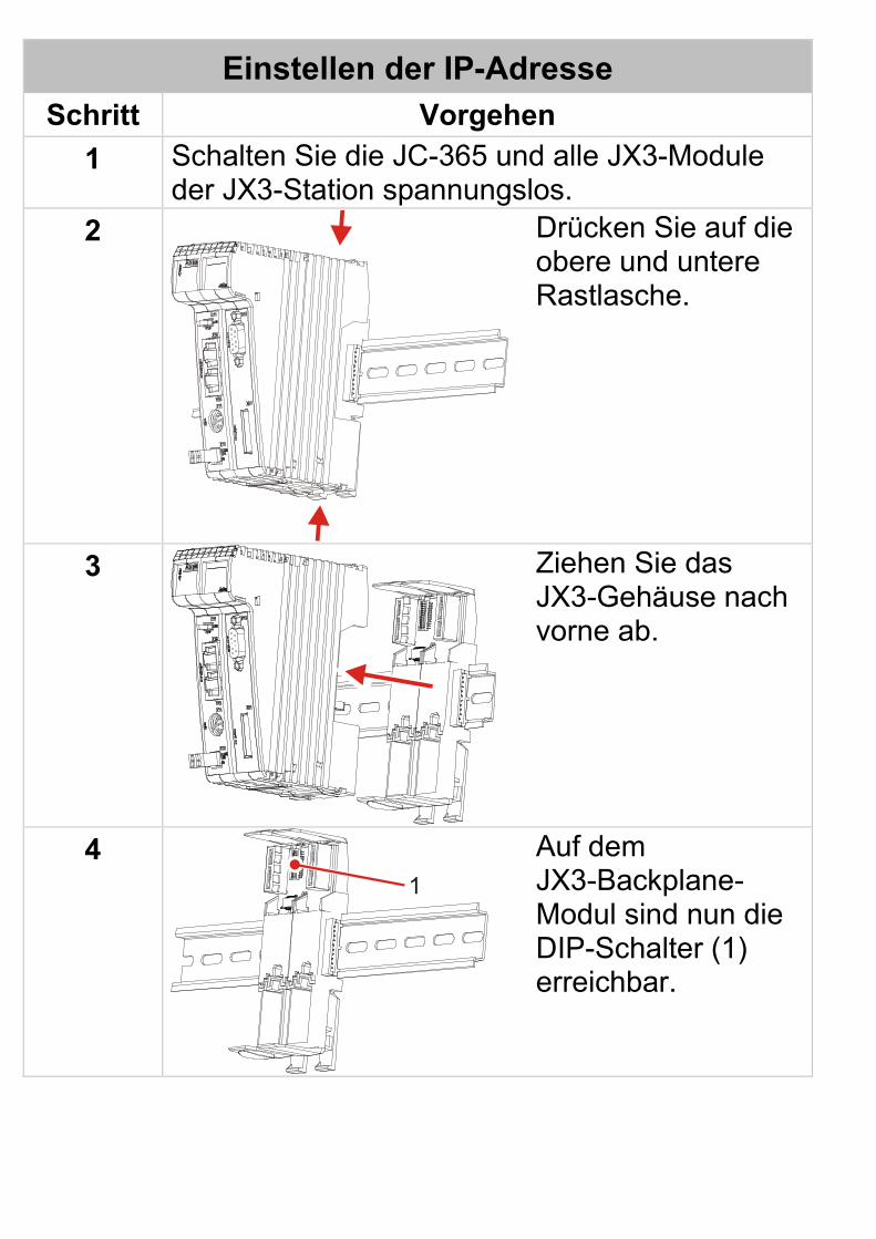
Einstellen der IP-Adresse Schritt Vorgehen
1 Schalten Sie die JC-365 und alle JX3-Module der JX3-Station spannungslos.
2
Drücken Sie auf die obere und untere Rastlasche.
3
Ziehen Sie das JX3-Gehäuse nach vorne ab.
4 1
Auf dem JX3-Backplane-Modul sind nun die DIP-Schalter (1) erreichbar.
Einstellen der IP-Adresse Schritt Vorgehen
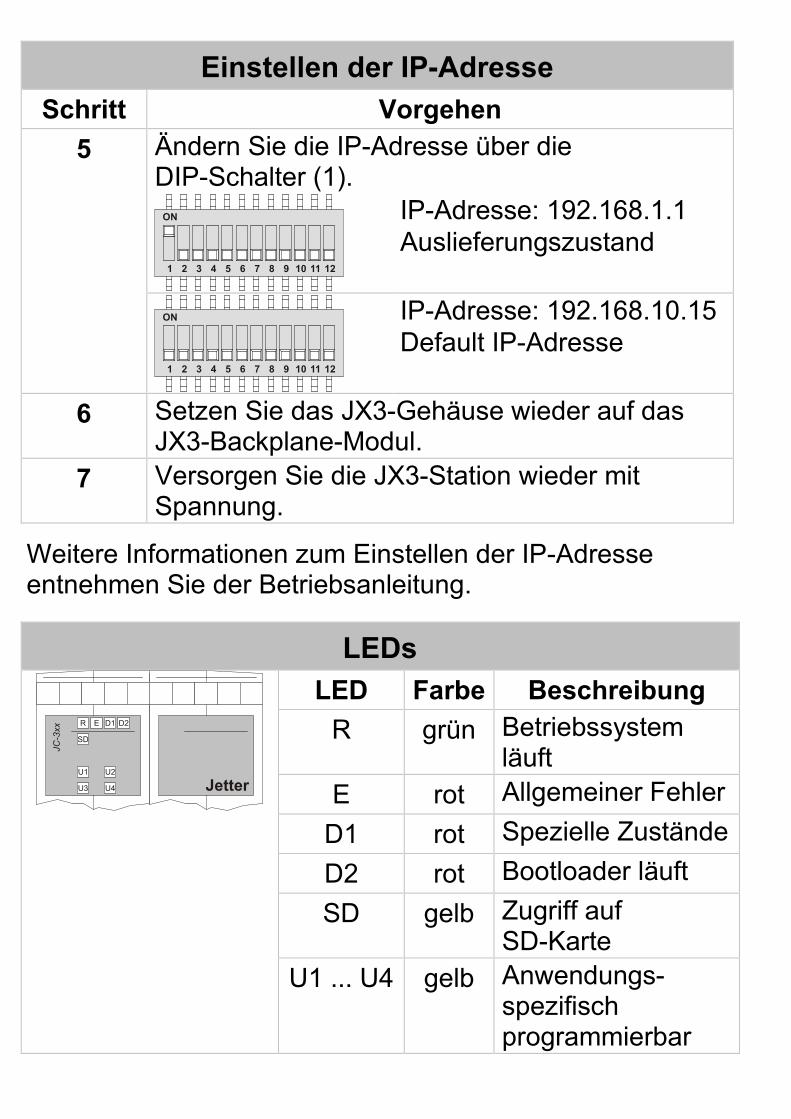
5 Ändern Sie die IP-Adresse über die DIP-Schalter (1).
ON
1 2 3 4 5 6 7 8 9 10 11 12
IP-Adresse: 192.168.1.1 Auslieferungszustand
ON
1 2 3 4 5 6 7 8 9 10 11 12
IP-Adresse: 192.168.10.15 Default IP-Adresse
6 Setzen Sie das JX3-Gehäuse wieder auf das JX3-Backplane-Modul.
7 Versorgen Sie die JX3-Station wieder mit Spannung.
Weitere Informationen zum Einstellen der IP-Adresse entnehmen Sie der Betriebsanleitung.
LEDs
R
SD
U1
U3 U4
U2
E D1 D2
JC-3
xx
Jetter
LED Farbe Beschreibung R grün Betriebssystem
läuft E rot Allgemeiner Fehler
D1 rot Spezielle Zustände D2 rot Bootloader läuft SD gelb Zugriff auf
SD-Karte U1 ... U4 gelb Anwendungs-
spezifisch programmierbar
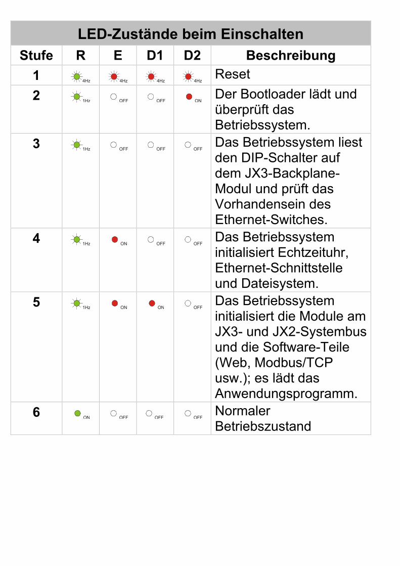
LED-Zustände beim Einschalten Stufe R E D1 D2 Beschreibung
1 4Hz 4Hz 4Hz 4Hz Reset 2 1Hz OFF OFF ON Der Bootloader lädt und
überprüft das Betriebssystem.
3 1Hz OFF OFF OFF Das Betriebssystem liest den DIP-Schalter auf dem JX3-Backplane-Modul und prüft das Vorhandensein des Ethernet-Switches.
4 1Hz ON OFF OFF Das Betriebssystem initialisiert Echtzeituhr, Ethernet-Schnittstelle und Dateisystem.
5 1Hz ON ON OFF Das Betriebssystem initialisiert die Module am JX3- und JX2-Systembus und die Software-Teile (Web, Modbus/TCP usw.); es lädt das Anwendungsprogramm.
6 ON OFF OFF OFF Normaler Betriebszustand
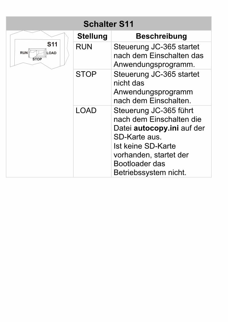
Schalter S11
S11RUN
STOP
LOAD
Stellung Beschreibung RUN Steuerung JC-365 startet
nach dem Einschalten das Anwendungsprogramm.
STOP Steuerung JC-365 startet nicht das Anwendungsprogramm nach dem Einschalten.
LOAD
Steuerung JC-365 führt nach dem Einschalten die Datei autocopy.ini auf der SD-Karte aus. Ist keine SD-Karte vorhanden, startet der Bootloader das Betriebssystem nicht.
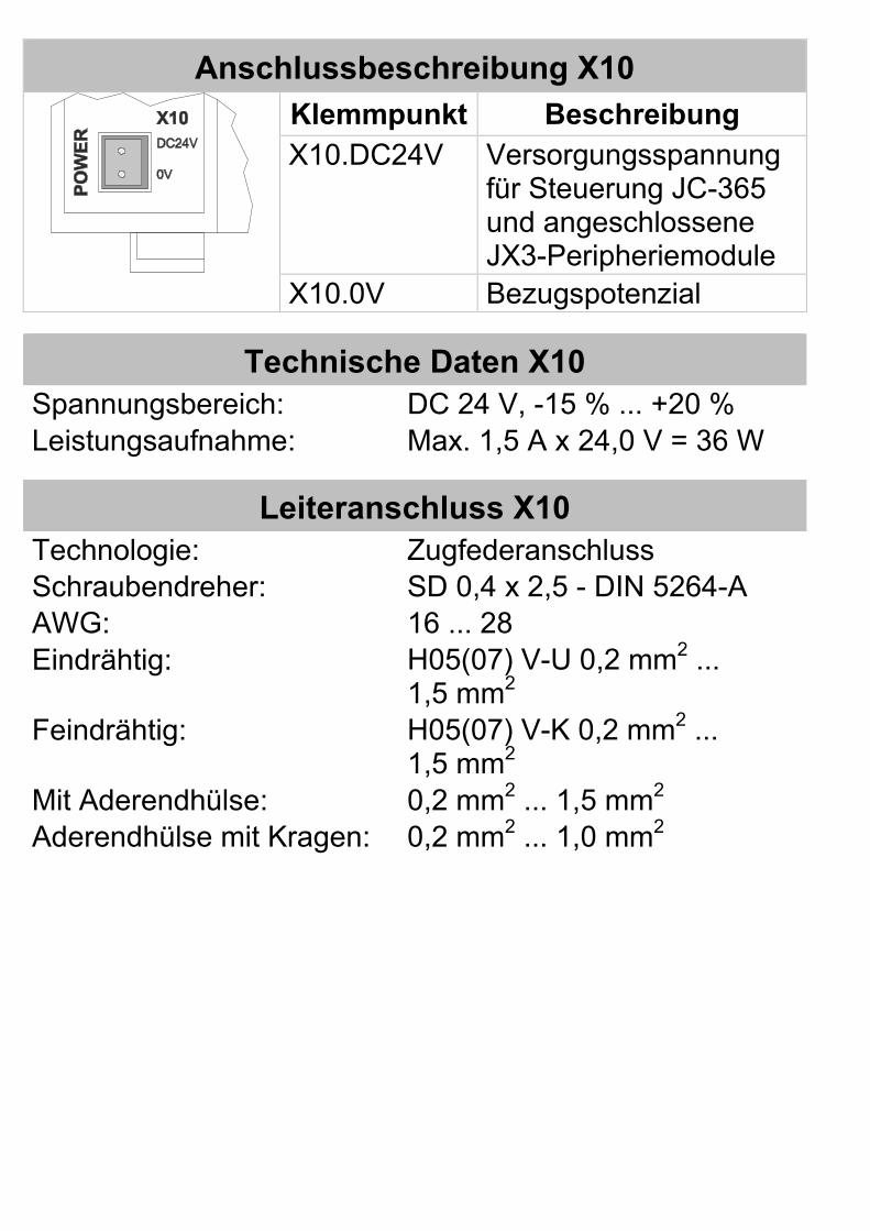
Anschlussbeschreibung X10
Klemmpunkt Beschreibung X10.DC24V Versorgungsspannung
für Steuerung JC-365 und angeschlossene JX3-Peripheriemodule
X10.0V Bezugspotenzial
Technische Daten X10 Spannungsbereich: DC 24 V, -15 % ... +20 % Leistungsaufnahme: Max. 1,5 A x 24,0 V = 36 W
Leiteranschluss X10 Technologie: Zugfederanschluss Schraubendreher: SD 0,4 x 2,5 - DIN 5264-A AWG: 16 ... 28 Eindrähtig: H05(07) V-U 0,2 mm2 ...
1,5 mm2 Feindrähtig: H05(07) V-K 0,2 mm2 ...
1,5 mm2 Mit Aderendhülse: 0,2 mm2 ... 1,5 mm2 Aderendhülse mit Kragen: 0,2 mm2 ... 1,0 mm2
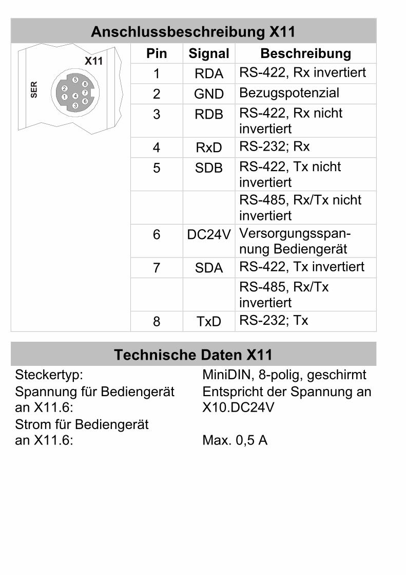
Anschlussbeschreibung X11
X11
SER
1
2
3
4
58
7
6
Pin Signal Beschreibung 1 RDA RS-422, Rx invertiert 2 GND Bezugspotenzial 3 RDB RS-422, Rx nicht
invertiert 4 RxD RS-232; Rx 5 SDB RS-422, Tx nicht
invertiert RS-485, Rx/Tx nicht
invertiert 6 DC24V Versorgungsspan-
nung Bediengerät 7 SDA RS-422, Tx invertiert RS-485, Rx/Tx
invertiert 8 TxD RS-232; Tx
Technische Daten X11 Steckertyp: MiniDIN, 8-polig, geschirmt Spannung für Bediengerät an X11.6:
Entspricht der Spannung an X10.DC24V
Strom für Bediengerät an X11.6:
Max. 0,5 A
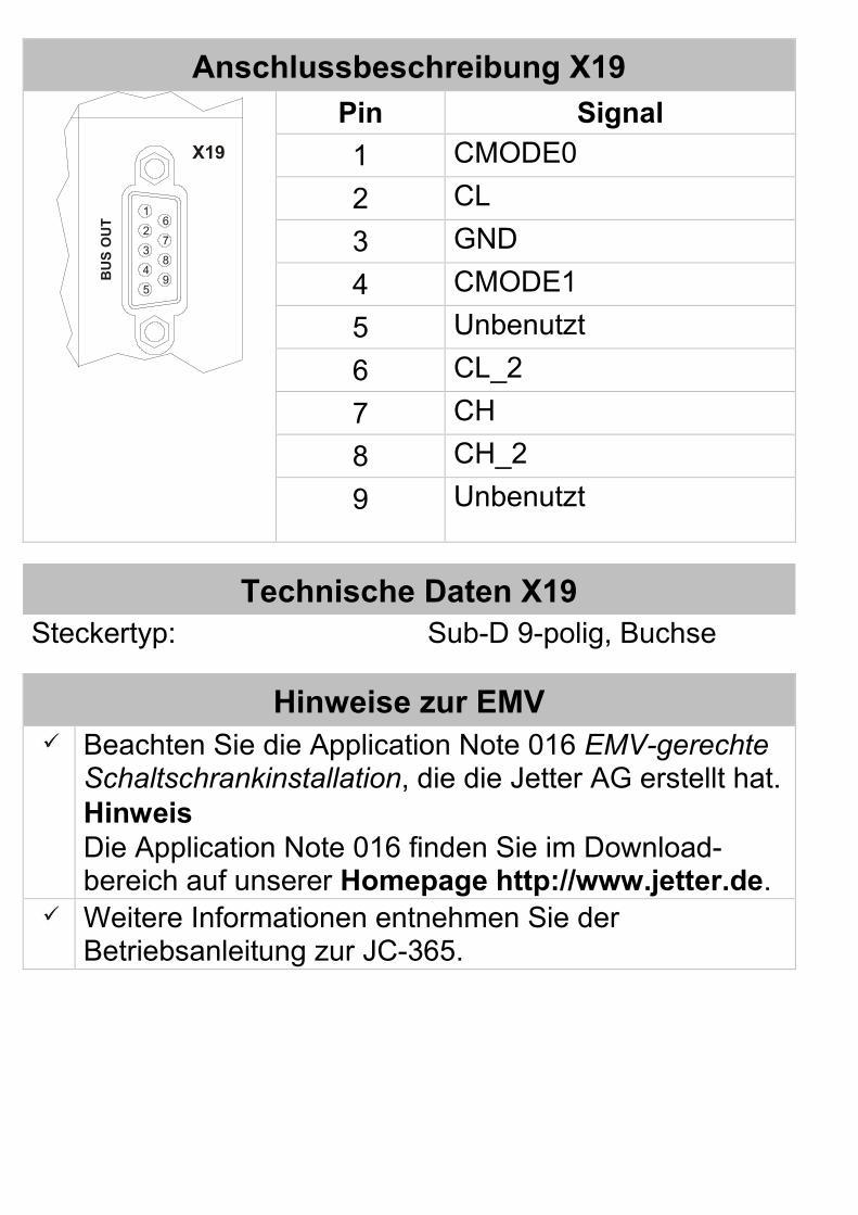
Anschlussbeschreibung X19 B
US
OU
T
X19
1
59
62
3
4
7
8
Pin Signal 1 CMODE0 2 CL 3 GND 4 CMODE1 5 Unbenutzt 6 CL_2 7 CH 8 CH_2 9
Unbenutzt
Technische Daten X19 Steckertyp: Sub-D 9-polig, Buchse
Hinweise zur EMV Beachten Sie die Application Note 016 EMV-gerechte
Schaltschrankinstallation, die die Jetter AG erstellt hat. Hinweis Die Application Note 016 finden Sie im Download-bereich auf unserer Homepage http://www.jetter.de.
Weitere Informationen entnehmen Sie der Betriebsanleitung zur JC-365.
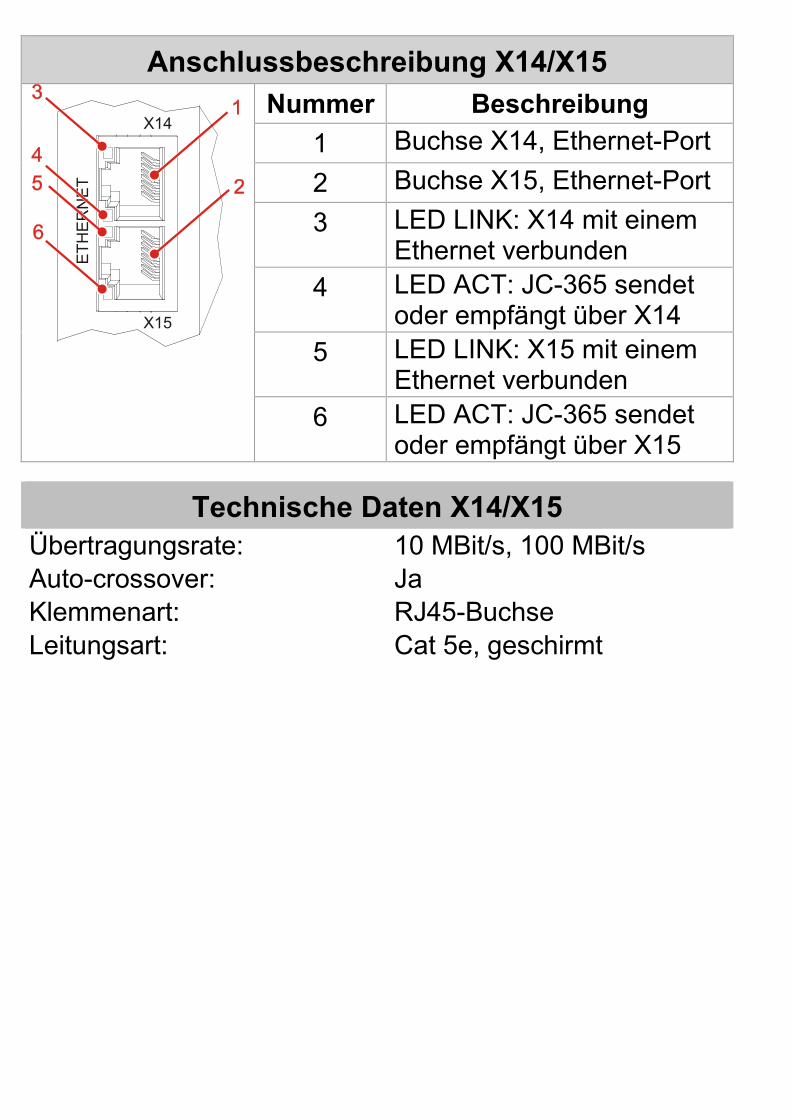
Anschlussbeschreibung X14/X15
X14
X15
ETH
ER
NE
T
Nummer Beschreibung 1 Buchse X14, Ethernet-Port 2 Buchse X15, Ethernet-Port 3 LED LINK: X14 mit einem
Ethernet verbunden 4 LED ACT: JC-365 sendet
oder empfängt über X14 5 LED LINK: X15 mit einem
Ethernet verbunden 6 LED ACT: JC-365 sendet
oder empfängt über X15
Technische Daten X14/X15 Übertragungsrate: 10 MBit/s, 100 MBit/s Auto-crossover: Ja Klemmenart: RJ45-Buchse Leitungsart: Cat 5e, geschirmt
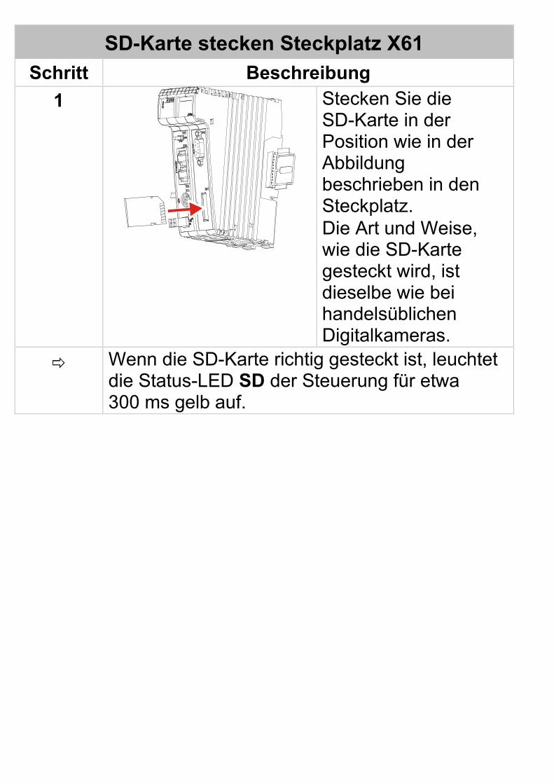
SD-Karte stecken Steckplatz X61 Schritt Beschreibung
1
Stecken Sie die SD-Karte in der Position wie in der Abbildung beschrieben in den Steckplatz. Die Art und Weise, wie die SD-Karte gesteckt wird, ist dieselbe wie bei handelsüblichen Digitalkameras.
Wenn die SD-Karte richtig gesteckt ist, leuchtet die Status-LED SD der Steuerung für etwa 300 ms gelb auf.
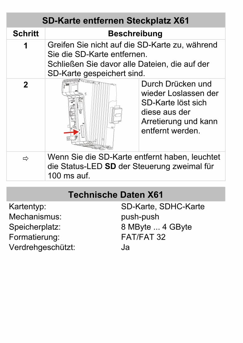
SD-Karte entfernen Steckplatz X61 Schritt Beschreibung
1 Greifen Sie nicht auf die SD-Karte zu, während Sie die SD-Karte entfernen. Schließen Sie davor alle Dateien, die auf der SD-Karte gespeichert sind.
2
Durch Drücken und wieder Loslassen der SD-Karte löst sich diese aus der Arretierung und kann entfernt werden.
Wenn Sie die SD-Karte entfernt haben, leuchtet die Status-LED SD der Steuerung zweimal für 100 ms auf.
Technische Daten X61 Kartentyp: SD-Karte, SDHC-Karte Mechanismus: push-push Speicherplatz: 8 MByte ... 4 GByte Formatierung: FAT/FAT 32 Verdrehgeschützt: Ja
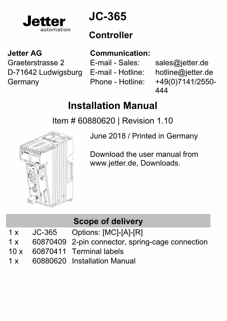
JC-365 Controller
Jetter AG Communication: Graeterstrasse 2 E-mail - Sales: [email protected] D-71642 Ludwigsburg E-mail - Hotline: [email protected] Germany Phone - Hotline: +49(0)7141/2550-
444
Installation Manual Item # 60880620 | Revision 1.10
June 2018 / Printed in Germany Download the user manual from www.jetter.de, Downloads.
Scope of delivery 1 x JC-365 Options: [MC]-[A]-[R] 1 x 60870409 2-pin connector, spring-cage connection 10 x 60870411 Terminal labels 1 x 60880620 Installation Manual
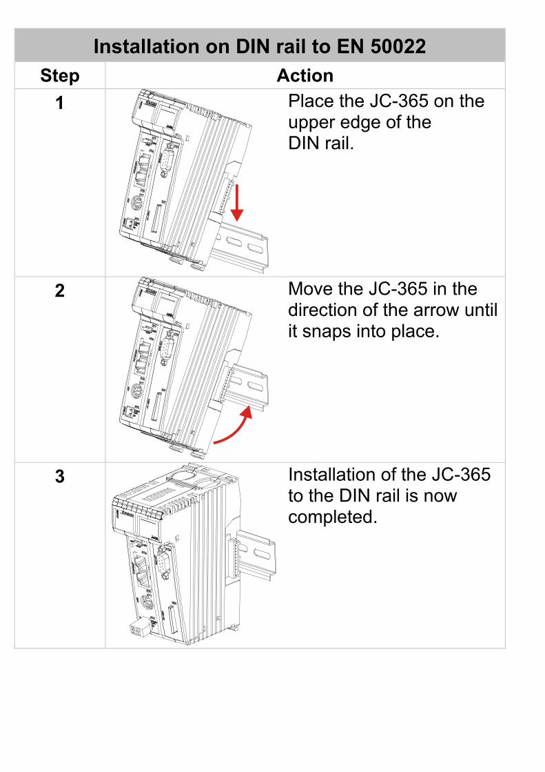
Installation on DIN rail to EN 50022 Step Action
1
Place the JC-365 on the upper edge of the DIN rail.
2
Move the JC-365 in the direction of the arrow until it snaps into place.
3
Installation of the JC-365 to the DIN rail is now completed.
Setting the IP address Step Action
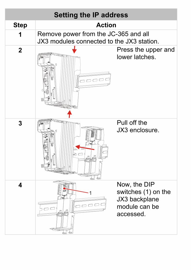
1 Remove power from the JC-365 and all JX3 modules connected to the JX3 station.
2
Press the upper and lower latches.
3
Pull off the JX3 enclosure.
4 1
Now, the DIP switches (1) on the JX3 backplane module can be accessed.
Setting the IP address Step Action
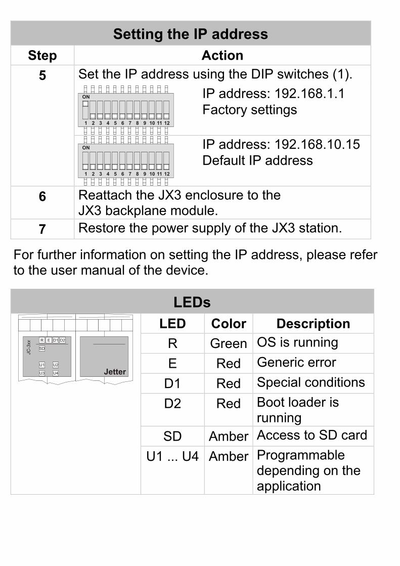
5 Set the IP address using the DIP switches (1).
ON
1 2 3 4 5 6 7 8 9 10 11 12
IP address: 192.168.1.1 Factory settings
ON
1 2 3 4 5 6 7 8 9 10 11 12
IP address: 192.168.10.15 Default IP address
6 Reattach the JX3 enclosure to the JX3 backplane module.
7 Restore the power supply of the JX3 station.
For further information on setting the IP address, please refer to the user manual of the device.
LEDs
R
SD
U1
U3 U4
U2
E D1 D2
JC-3
xx
Jetter
LED Color Description R Green OS is running E Red Generic error
D1 Red Special conditions D2 Red Boot loader is
running SD Amber Access to SD card
U1 ... U4 Amber Programmable depending on the application
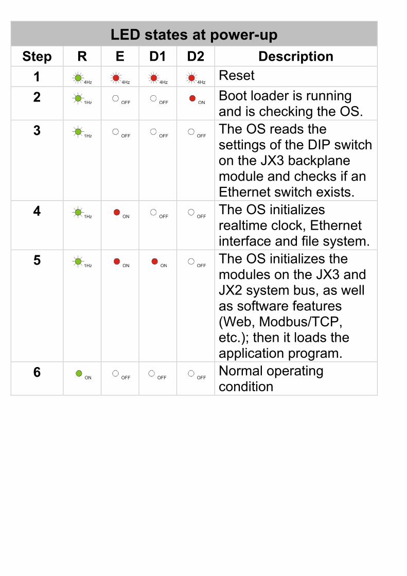
LED states at power-up Step R E D1 D2 Description
1 4Hz 4Hz 4Hz 4Hz Reset 2 1Hz OFF OFF ON Boot loader is running
and is checking the OS. 3 1Hz OFF OFF OFF The OS reads the
settings of the DIP switch on the JX3 backplane module and checks if an Ethernet switch exists.
4 1Hz ON OFF OFF The OS initializes realtime clock, Ethernet interface and file system.
5 1Hz ON ON OFF The OS initializes the modules on the JX3 and JX2 system bus, as well as software features (Web, Modbus/TCP, etc.); then it loads the application program.
6 ON OFF OFF OFF Normal operating condition
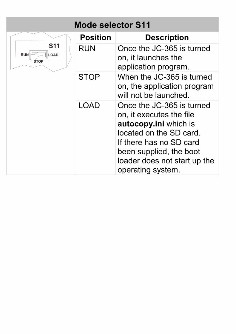
Mode selector S11
S11RUN
STOP
LOAD
Position Description RUN Once the JC-365 is turned
on, it launches the application program.
STOP When the JC-365 is turned on, the application program will not be launched.
LOAD
Once the JC-365 is turned on, it executes the file autocopy.ini which is located on the SD card. If there has no SD card been supplied, the boot loader does not start up the operating system.
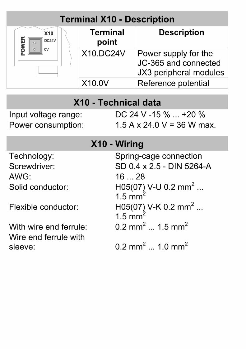
Terminal X10 - Description
Terminal point
Description
X10.DC24V Power supply for the JC-365 and connected JX3 peripheral modules
X10.0V Reference potential
X10 - Technical data Input voltage range: DC 24 V -15 % ... +20 % Power consumption: 1.5 A x 24.0 V = 36 W max.
X10 - Wiring Technology: Spring-cage connection Screwdriver: SD 0.4 x 2.5 - DIN 5264-A AWG: 16 ... 28 Solid conductor: H05(07) V-U 0.2 mm2 ...
1.5 mm2 Flexible conductor: H05(07) V-K 0.2 mm2 ...
1.5 mm2 With wire end ferrule: 0.2 mm2 ... 1.5 mm2 Wire end ferrule with sleeve:
0.2 mm2 ... 1.0 mm2
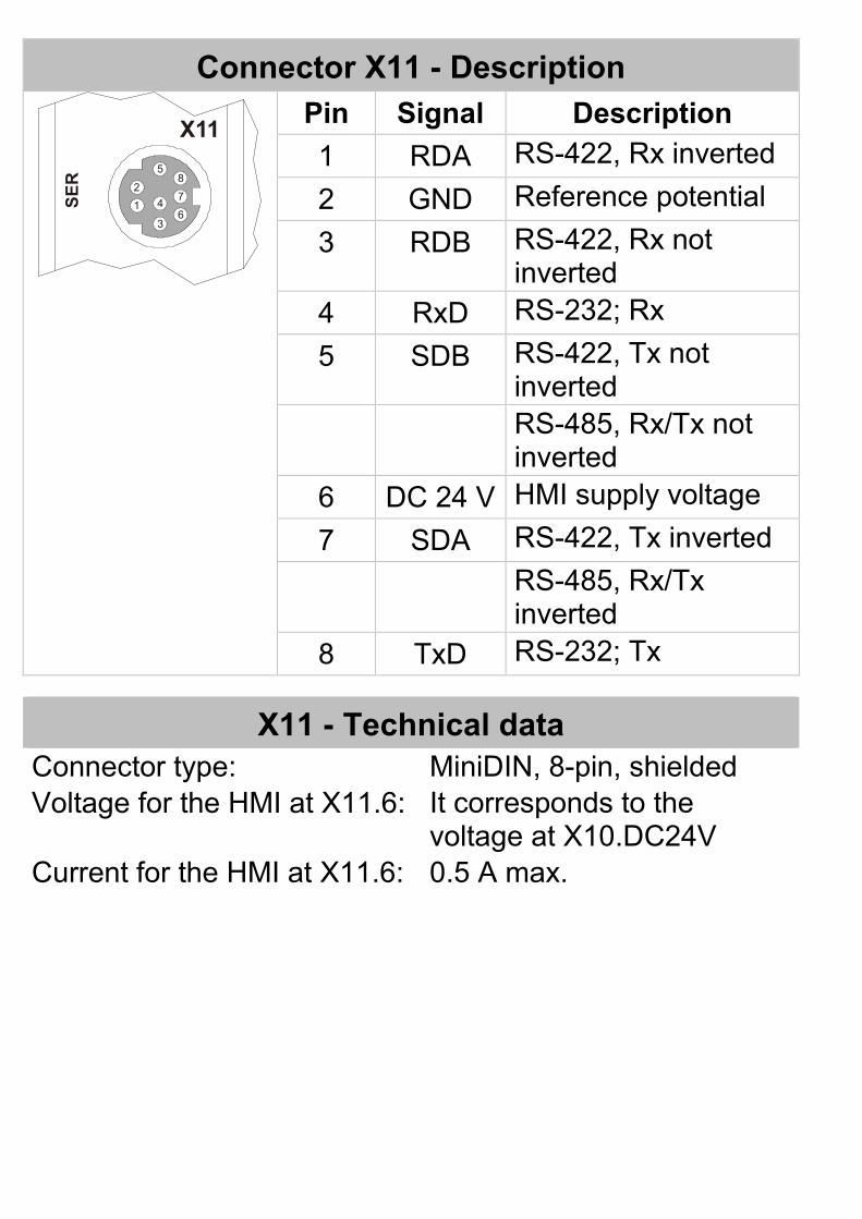
Connector X11 - Description
X11
SER
1
2
3
4
58
7
6
Pin Signal Description 1 RDA RS-422, Rx inverted 2 GND Reference potential 3 RDB RS-422, Rx not
inverted 4 RxD RS-232; Rx 5 SDB RS-422, Tx not
inverted RS-485, Rx/Tx not
inverted 6 DC 24 V HMI supply voltage 7 SDA RS-422, Tx inverted RS-485, Rx/Tx
inverted 8 TxD RS-232; Tx
X11 - Technical data Connector type: MiniDIN, 8-pin, shielded Voltage for the HMI at X11.6: It corresponds to the
voltage at X10.DC24V Current for the HMI at X11.6: 0.5 A max.
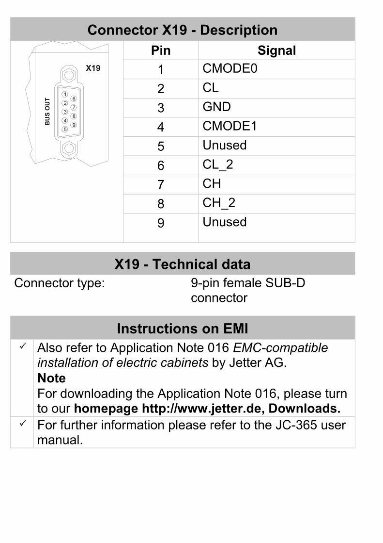
Connector X19 - Description B
US
OU
T
X19
1
59
62
3
4
7
8
Pin Signal 1 CMODE0 2 CL 3 GND 4 CMODE1 5 Unused 6 CL_2 7 CH 8 CH_2 9
Unused
X19 - Technical data Connector type: 9-pin female SUB-D
connector
Instructions on EMI Also refer to Application Note 016 EMC-compatible
installation of electric cabinets by Jetter AG. Note For downloading the Application Note 016, please turn to our homepage http://www.jetter.de, Downloads.
For further information please refer to the JC-365 user manual.
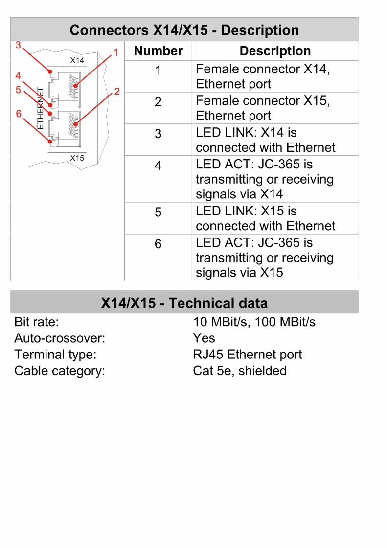
Connectors X14/X15 - Description
X14
X15
ETH
ER
NE
T
Number Description 1 Female connector X14,
Ethernet port 2 Female connector X15,
Ethernet port 3 LED LINK: X14 is
connected with Ethernet 4 LED ACT: JC-365 is
transmitting or receiving signals via X14
5 LED LINK: X15 is connected with Ethernet
6 LED ACT: JC-365 is transmitting or receiving signals via X15
X14/X15 - Technical data Bit rate: 10 MBit/s, 100 MBit/s Auto-crossover: Yes Terminal type: RJ45 Ethernet port Cable category: Cat 5e, shielded
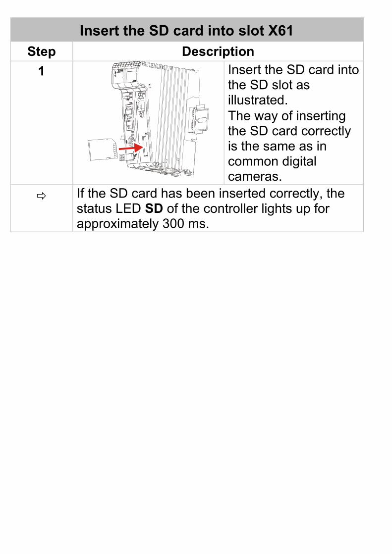
Insert the SD card into slot X61 Step Description
1
Insert the SD card into the SD slot as illustrated. The way of inserting the SD card correctly is the same as in common digital cameras.
If the SD card has been inserted correctly, the status LED SD of the controller lights up for approximately 300 ms.
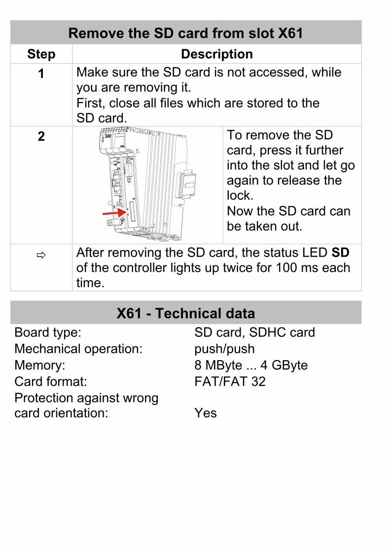
Remove the SD card from slot X61 Step Description
1 Make sure the SD card is not accessed, while you are removing it. First, close all files which are stored to the SD card.
2
To remove the SD card, press it further into the slot and let go again to release the lock. Now the SD card can be taken out.
After removing the SD card, the status LED SD of the controller lights up twice for 100 ms each time.
X61 - Technical data Board type: SD card, SDHC card Mechanical operation: push/push Memory: 8 MByte ... 4 GByte Card format: FAT/FAT 32 Protection against wrong card orientation:
Yes