Embed Size (px)
Citation preview
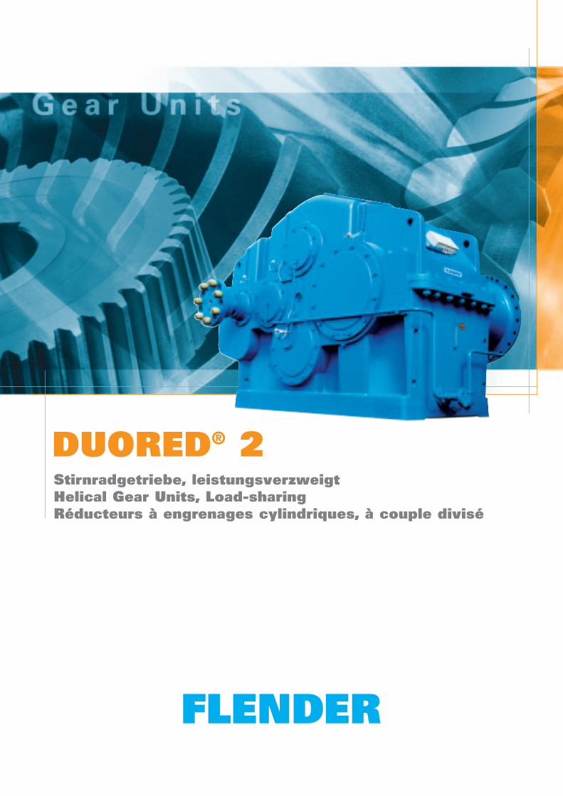
DUORED® 2Stirnradgetriebe, leistungsverzweigtHelical Gear Units, Load-sharingRéducteurs à engrenages cylindriques, à couple divisé
K228 DE/EN/FR2
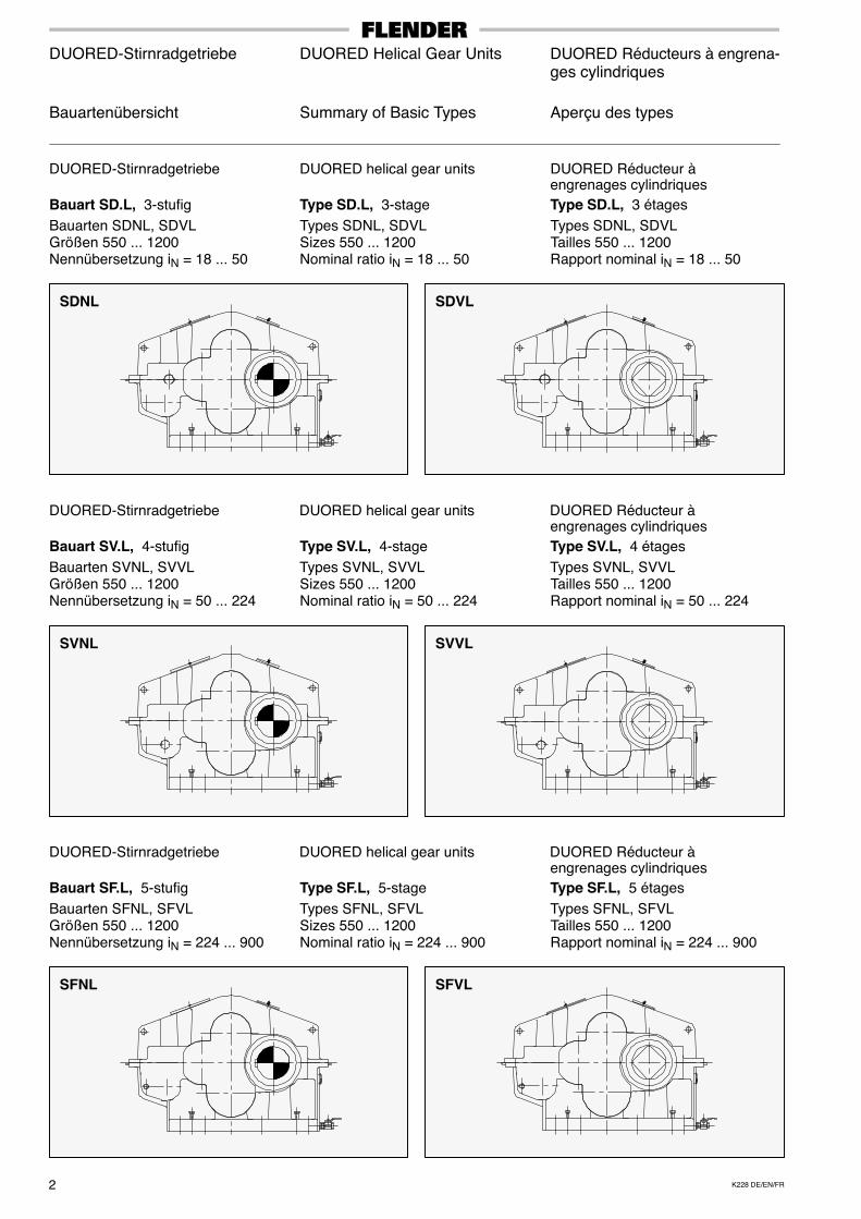
DUORED-Stirnradgetriebe DUORED Helical Gear Units DUORED Réducteurs à engrena-ges cylindriques
Bauartenübersicht Summary of Basic Types Aperçu des types
DUORED-Stirnradgetriebe DUORED helical gear units DUORED Réducteur àengrenages cylindriques
Bauart SD.L, 3-stufig Type SD.L, 3-stage Type SD.L, 3 étages
Bauarten SDNL, SDVL Types SDNL, SDVL Types SDNL, SDVLGrößen 550 ... 1200 Sizes 550 ... 1200 Tailles 550 ... 1200Nennübersetzung iN = 18 ... 50 Nominal ratio iN = 18 ... 50 Rapport nominal iN = 18 ... 50
DUORED-Stirnradgetriebe DUORED helical gear units DUORED Réducteur àengrenages cylindriques
Bauart SV.L, 4-stufig Type SV.L, 4-stage Type SV.L, 4 étages
Bauarten SVNL, SVVL Types SVNL, SVVL Types SVNL, SVVLGrößen 550 ... 1200 Sizes 550 ... 1200 Tailles 550 ... 1200Nennübersetzung iN = 50 ... 224 Nominal ratio iN = 50 ... 224 Rapport nominal iN = 50 ... 224
DUORED-Stirnradgetriebe DUORED helical gear units DUORED Réducteur àengrenages cylindriques
Bauart SF.L, 5-stufig Type SF.L, 5-stage Type SF.L, 5 étages
Bauarten SFNL, SFVL Types SFNL, SFVL Types SFNL, SFVLGrößen 550 ... 1200 Sizes 550 ... 1200 Tailles 550 ... 1200Nennübersetzung iN = 224 ... 900 Nominal ratio iN = 224 ... 900 Rapport nominal iN = 224 ... 900
SDNL SDVL
SVNL SVVL
SFNL SFVL
3K228 DE/EN/FR
DUORED-Stirnradgetriebe DUORED Helical Gear Units DUORED Réducteurs à engrena-ges cylindriques
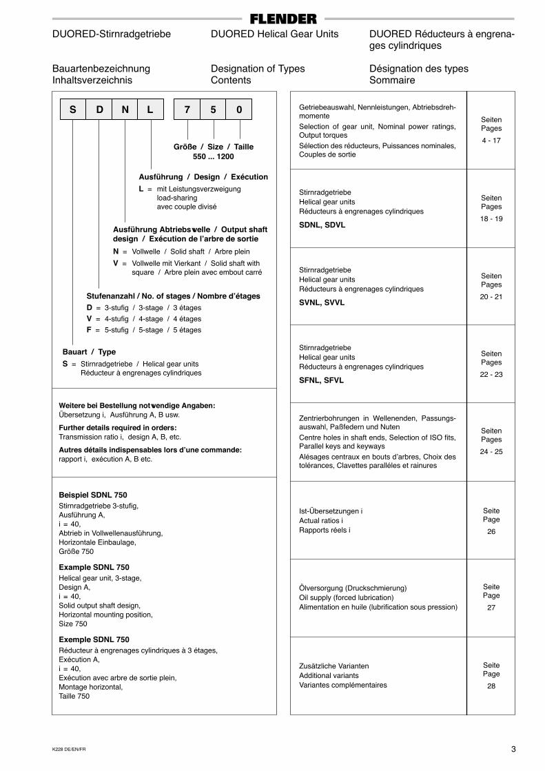
Bauartenbezeichnung Designation of Types Désignation des typesInhaltsverzeichnis Contents Sommaire
Bauart / Type
S = Stirnradgetriebe / Helical gear unitsRéducteur à engrenages cylindriques
Ausführung / Design / Exécution
L = mit Leistungsverzweigungload-sharingavec couple divisé
Größe / Size / Taille550 ... 1200
S D N L 7 5
Weitere bei Bestellung notwendige Angaben:Übersetzung i, Ausführung A, B usw.
Further details required in orders:Transmission ratio i, design A, B, etc.
Autres détails indispensables lors d’une commande:rapport i, exécution A, B etc.
Beispiel SDNL 750Stirnradgetriebe 3-stufig,Ausführung A,i = 40,Abtrieb in Vollwellenausführung,Horizontale Einbaulage,Größe 750
Example SDNL 750Helical gear unit, 3-stage,Design A,i = 40,Solid output shaft design,Horizontal mounting position,Size 750
Exemple SDNL 750Réducteur à engrenages cylindriques à 3 étages,Exécution A,i = 40,Exécution avec arbre de sortie plein,Montage horizontal,Taille 750
SeitenPages
4 - 17
SeitePage
26
SeitenPages
20 - 21
SeitenPages
18 - 19
SeitePage
28
Getriebeauswahl, Nennleistungen, Abtriebsdreh-momente
Selection of gear unit, Nominal power ratings,Output torques
Sélection des réducteurs, Puissances nominales,Couples de sortie
Stirnradgetriebe
Helical gear units
Réducteurs à engrenages cylindriques
SDNL, SDVL
Stirnradgetriebe
Helical gear units
Réducteurs à engrenages cylindriques
SVNL, SVVL
Ist-Übersetzungen i
Actual ratios i
Rapports réels i
Zusätzliche Varianten
Additional variants
Variantes complémentaires
0
Ausführung Abtriebswelle / Output shaftdesign / Exécution de l’arbre de sortie
N = Vollwelle / Solid shaft / Arbre plein
V = Vollwelle mit Vierkant / Solid shaft withsquare / Arbre plein avec embout carré
Stufenanzahl / No. of stages / Nombre d’étagesD = 3-stufig / 3-stage / 3 étages
V = 4-stufig / 4-stage / 4 étages
F = 5-stufig / 5-stage / 5 étages
SeitenPages
22 - 23
Stirnradgetriebe
Helical gear units
Réducteurs à engrenages cylindriques
SFNL, SFVL
SeitenPages
24 - 25
Zentrierbohrungen in Wellenenden, Passungs-auswahl, Paßfedern und Nuten
Centre holes in shaft ends, Selection of ISO fits,Parallel keys and keyways
Alésages centraux en bouts d’arbres, Choix destolérances, Clavettes paralléles et rainures
SeitePage
27
Ölversorgung (Druckschmierung)
Oil supply (forced lubrication)
Alimentation en huile (lubrification sous pression)
K228 DE/EN/FR4
DUORED-Stirnradgetriebe DUORED Helical Gear Units DUORED Réducteurs à engrena-ges cylindriques
Charakteristische Vorzüge Characteristic Features Caractéristiques
KonstruktionDurch Leistungsverzweigung wird die eingeleiteteAntriebsleistung auf zwei Stränge aufgeteilt undüber die Stirnritzel beider Stränge auf das Zahn-rad der Abtriebsstufe gebracht. So wird das großeZahnrad der Abtriebsstufe mehrfach genutzt undkann dadurch in den Abmessungen kleiner ge-staltet werden. Hieraus resultiert eine hohe über-tragbare Leistung je Raumeinheit bei geringemGewicht. Pluspunkte sind:
� verwindungssteifes Gehäuse in Fußaus-führung. Die Gehäuse werden in GG 20, inSonderfällen aus GGG 40 oder aus Stahl-Schweißkonstruktion gefertigt.
� Stirnräder und Stirnradwellen sind schräg-verzahnt, im Einsatz gehärtet und korrektur-geschliffen.
� Lagerung der Zahnräder und Wellen erfolgtausschließlich durch ausreichend dimen-sionierte Wälzlager.
� Bei den Bauarten S.VL ist die Abtriebswelle alsVollwelle mit Vierkant und beidseitig wirkendemAxiallager zur Aufnahme von äußeren Axial-kräften in beiden Richtungen vorgesehen.(Bauarten S.NL mit beidseitig wirkendem Axial-lager auf Anfrage).
� Standardmäßig erfolgt die Ölversorgung derZahnräder und Wälzlager durch eine kom-binierte Tauch- und Druckschmierung.
Es kommen getrennt aufgestellte Ölver-sorgungsanlagen mit Motorölpumpe, Ölkühler,Doppelschaltfilter und diversen Über-wachungsgeräten, komplett auf einem Grund-rahmen montiert, zur Anwendung.
EinbaulageDUORED-Stirnradgetriebe sind nur für hori-zontale Einbaulage lieferbar.
GeräuschverhaltenDie Getriebe sind geräuschoptimiert und könnennach VDI 2159 entsprechend der Leistung be-urteilt werden.
Temperaturverhalten
DUORED-Stirnradgetriebe haben durch ihren gu-ten Wirkungsgrad ein günstiges Temperaturver-halten.
Bei der Getriebeauswahl legt Flender eineniedrige maximale Öltemperatur zugrunde. DieBetriebssicherheit wird dadurch erhöht, und derWartungsaufwand verringert sich durch längereÖlstandszeiten.
Eine Demontage des DUORED-Stirnradge-triebes darf nur nach Anleitung und mit Vor-richtungen (Nummern siehe Hinweisschildam Getriebe) erfolgen.
DesignIn this load-sharing system, the input power isdivided between two gear trains and transmittedto the output gear via the helical pinions of bothtrains. In this way, the large gear of the outputstage is used several times and can thereforebe kept smaller. This results in a high tranmis-sible power per unit of volume at a low weight.The advantages are:
� Torsionally rigid housing in foot-mounteddesign. The housings are made out of GG 20,in special cases of GGG 40, or of fabricatedsteel.
� Helical gears and helical pinion shafts are casehardened and with gear teeth modifications.
� Gears and shafts are exclusively supported byamply dimensioned rolling bearings.
� With the S.VL types, the output shaft is de-signed as a solid shaft with square and a thrustbearing acting on both sides to absorb externalaxial forces in both directions. (Types S.NL withthrust bearings acting on both sides are avail-able on request.)
� As standard, oil is supplied to the gears and roll-ing bearing by a combination of dip and forcedlubrication.
Separate oil supply systems with motor oilpump, oil cooler, double change-over filter andvarious monitoring instruments are used, all ofwhich are mounted on a base frame.
Mounting positionDUORED helical gear units can be supplied forhorizontal installation only.
Noise behaviourThe gear units are optimized regarding noiseemission and can be weighted according to VDI2159, depending on the power rating.
Thermal conduction
DUORED helical gear units not only have a highefficiency but also a favourable thermal conduc-tion.
Flender bases the selection of gear units on a lowmaximum oil temperature. This increases theoperational reliability and reduces the mainte-nance costs through longer oil life.
DUORED helical gear units may be dis-mantled only in accordance with the in-structions and with the respective jigs andfixtures (for numbers, see gear unit ratingplate).
ConceptionAu moyen du couple divisé, la puissance d’entréeest répartie sur deux arbres et transmise autrain d’engrenage de sortie par l’intermédiairedes pignons hélicoïdaux de ces deux arbres.L’entraînement de la grande roue de sortie parplusieurs pignons permet de réduire les di-mensions de cette roue. Il en résulte une trans-mission de puissance élevée par unité d’espaceavec un faible poids. Les avantages qui enrésultent sont les suivants:
� Carter indéformable en version à pattes. Lescarters sont fabriqués en fonte grise GG 20,dans des cas particuliers en fonte à graphitesphéroïdal GGG 40 ou en acier mécanosoudé.
� Les engrenages cylindriques et les pignonsarbrés sont à denture hélicoïdale, cémentéset rectifiés.
� Le logement des engrenages et des arbress’effectue uniquement dans des roulementslargement dimensionnés.
� Sur les modèles S.VL, l’arbre de sortie estun arbre plein à embout carré et palier axialà effet bilatéral absorbant les forces axialesextérieures dans les deux sens (sur demande,modèles S.NL à palier axial n’agissant qued’un côté).
� L’alimentation standard en huile des engrena-ges et des roulements à rouleaux a lieu sousforme de lubrification combinée par barbotageet sous pression.Un système de lubrification séparé est em-ployé, ce dernier comprend un groupe moto-pompe, un dispositif de réfrigération, un filtreà double action et divers appareils de con-trôle, il est monté entièrement sur un chassissupport.
Position de montageLes DUORED Réducteurs à engrenages cylindri-ques ne sont livrables que pour un montage enposition horizontale.
Niveau de bruitLes réducteurs sont phoniquement optimisés etpeuvent être jugés en fonction de leur puissanceselon VDI 2159.
Comportement en fonction de la tempé-ratureLes réducteurs DUORED à engrenages cylindri-ques présentent en fonction de la température,un comportement favorable avec un rendementélevé.Lors du choix du réducteur, Flender définit unevaleur assez basse pour la température d’huilemaximale ce qui permet d’augmenter la fiabilité defonctionnement et de diminuer l’entretien par unedurée de vie accrue de l’huile.
Le démontage du réducteur DUORED à en-grenages cylindriques ne peut s’effectuerque suivant les instructions et à l’aide dedispositifs adéquats (voir références indi-quées sur la plaque fixée au réducteur).

5K228 DE/EN/FR
DUORED-Stirnradgetriebe DUORED Helical Gear Units DUORED Réducteurs à engrena-ges cylindriques
Allgemeine Hinweise General Information Informations générales
Achtung!
Folgende Punkte sind unbedingt zubeachten!
� Abbildungen sind beispielhaft undnicht verbindlich. Maßänderungenbleiben vorbehalten.
� Die angegebenen Gewichte sindunverbindliche Mittelwerte.
� Umlaufende Teile müssen vomKäufer gegen unbeabsichtigtesBerühren geschützt werden.Die gültigen Sicherheitsbestimmun-gen des jeweiligen Einsatzlandessind zu beachten.
� Vor Inbetriebnahme ist die Betriebs-anleitung zu beachten.Die Getriebe werden betriebsfertig,jedoch ohne Ölfüllung geliefert.
� Ölmengenangaben sind unverbind-liche Richtwerte.Maßgebend ist die Ölstandsmar-kierung am Ölmeßstab bzw. Ölauge.
� Ölviskosität muß den Angaben desTypenschildes entsprechen.
� Es dürfen nur freigegebeneSchmierstoffe verwendet werden.Aktuelle Betriebsanleitungen undSchmierstofftabellen finden Sie aufunserer Homepage unter:www.flender.com
� Die Getriebe werden mit Radialwel-lendichtringen ausgeliefert. AndereDichtungsvarianten auf Anfrage.
� Die Drehrichtungsangaben be-ziehen sich auf die Abtriebswelle d2mit Blick auf den Wellenspiegel.
Erklärung der Symbole in den Maß-zeichnungen:
= Ölauge
= Entlüftung
= Ölablaß
= Öleinfüllung
Getriebe mit Druckschrauben imGehäusefuß und Ausrichtflächen amGehäuse.
Fußschrauben mit Mindest-Festig-keitsklasse 8.8.Die Getriebe sind konserviert und imFarbton RAL 5015 lackiert.
Attention!
The following items are absolutely tobe observed!
� Illustrations are examples only andare not strictly binding. Dimensionsare subject to change.
� The weights are mean values andnot strictly binding.
� To prevent accidents, all rotatingparts should be guarded accordingto local and national safety regula-tions.
� Prior to commissioning, carefullyread the operating instructions.The gear units are delivered readyfor operation but without oil filling.
� Oil quantities given are guide valuesonly. The exact quantity of oildepends on the mark on the oil dip-stick or oil sight glass.
� The oil viscosity has to correspondto the data given on the name plate.
� Permitted lubricants may be usedonly.You will find current operatinginstructions and lubricant selectiontables on our home page at:www.flender.com
� The gear units are supplied withradial shaft seals. Other sealingvariants on request.
� The specified directions of rotationrefer to output shaft d2 viewing onthe shaft end face.
Explanation of symbols used in thedimensioned drawings:
= Oil sight glass
= Breather
= Oil drain
= Oil filler
Gear units with jack screws in thehousing feet, and leveling pads on thehousing.
Foundation bolts of min. propertyclass 8.8.The gear housings are protectedagainst corrosion and sprayed in RAL5015.
Attention!
Les points suivants doivent impérati-vement être respectés!
� Les schémas sont donnés à titreindicatif, sans engagement. Nousnous réservons le droit de modifierles cotes indiquées.
� Les poids sont des valeurs indica-tives.
� L’acheteur s’engage à protéger lespièces rotatives contre tout contactaccidentel. Les consignes de sécu-rité en vigueur dans chaque paysd’utilisation doivent être respec-tées.
� Avant la mise en service, lire attenti-vement les instructions de service.Les réducteurs sont livrés finis defabrication mais sans huile.
� Les quantités d’huile données sontdes valeurs indicatives sans enga-gement. La quantité d’huile exactedépend des repéres sur la jauge deniveau d’huile ou le regard de con-trôle d’huile.
� La viscosité de l’huile doit êtreconforme aux indications de laplaque signalétique.
� Seuls les lubrifiants homologuéssont autorisés. Vous trouverez nosmanuels d’utilisation en vigueuravec les tableaux des lubrifiants re-commandés sur notre site internet:www.flender.com
� Les réducteurs sont équipés debagues d’étanchéité. D’autres typesd’étanchéité sur demande.
� Les indications concernant les sensde rotation se rapportent sur l’arbrede sortie d2 en regardant le boutd’arbre.
Explication des symboles utiliséspour les mesures:
= Niveau d’huile visible
= Réniflard
= Orifice de vidange d’huile
= Orifice de remplissage
Des vis de réglage sont prévues dansla semelle du carter et des faces deréférences sont prévues sur la partiesupérieure du carter.Vis de fixation en classe 8.8. mini.
Les carters reçoivent un traitementanti-corrosion et sont peints en RAL5015.
K228 DE/EN/FR6
DUORED-Stirnradgetriebe DUORED Helical Gear Units DUORED Réducteurs à engrena-ges cylindriques
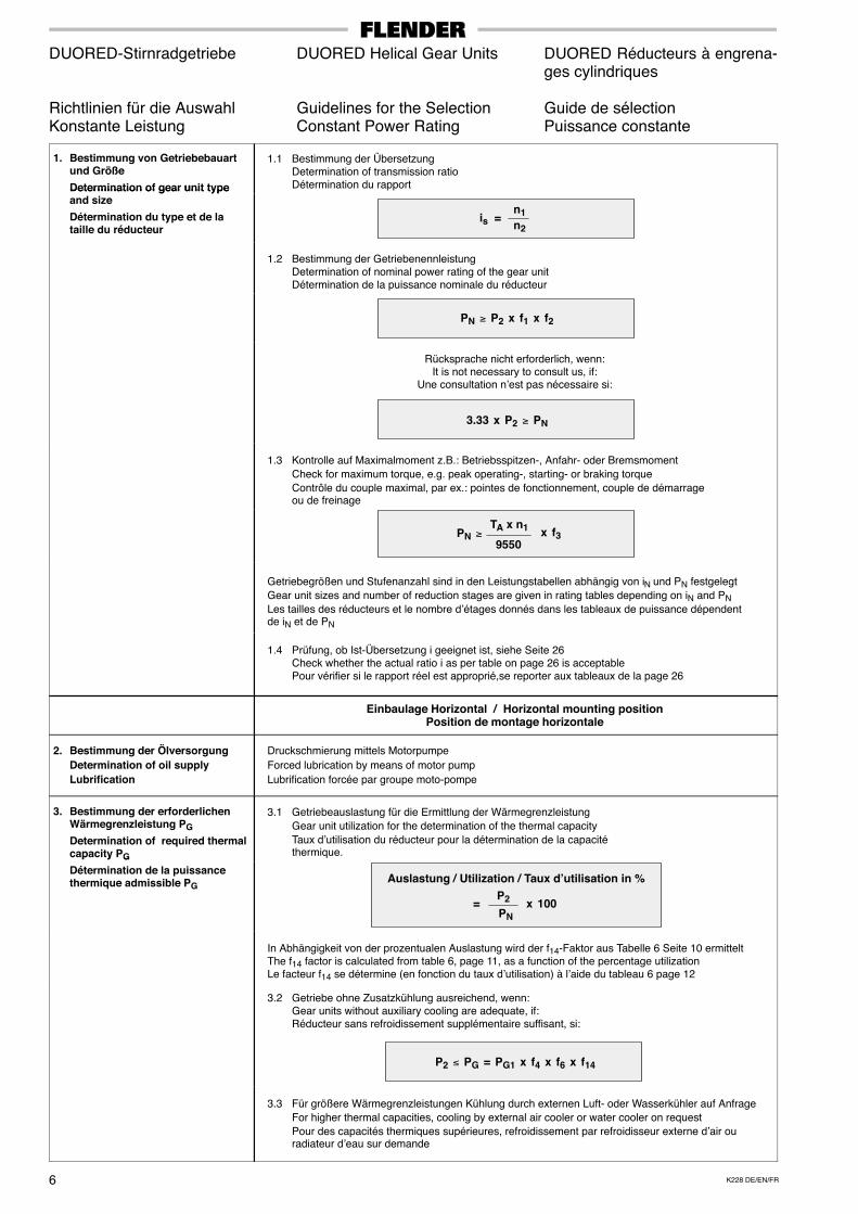
Richtlinien für die Auswahl Guidelines for the Selection Guide de sélectionKonstante Leistung Constant Power Rating Puissance constante
1. Bestimmung von Getriebebauartund Größe
Determination of gear unit type
1.1 Bestimmung der ÜbersetzungDetermination of transmission ratioDétermination du rapportDetermination of gear unit type
and size
Détermination du type et de lataille du réducteur
is =n1n2
1.2 Bestimmung der GetriebenennleistungDetermination of nominal power rating of the gear unitDétermination de la puissance nominale du réducteur
PN ≥ P2 x f1 x f2
Rücksprache nicht erforderlich, wenn:It is not necessary to consult us, if:
Une consultation n’est pas nécessaire si:
3.33 x P2 ≥ PN
1.3 Kontrolle auf Maximalmoment z.B.: Betriebsspitzen-, Anfahr- oder Bremsmoment
Check for maximum torque, e.g. peak operating-, starting- or braking torque
Contrôle du couple maximal, par ex.: pointes de fonctionnement, couple de démarrageou de freinage
PN ≥TA x n1
9550 x f3
Getriebegrößen und Stufenanzahl sind in den Leistungstabellen abhängig von iN und PN festgelegt
Gear unit sizes and number of reduction stages are given in rating tables depending on iN and PN
Les tailles des réducteurs et le nombre d’étages donnés dans les tableaux de puissance dépendentde iN et de PN
1.4 Prüfung, ob Ist-Übersetzung i geeignet ist, siehe Seite 26Check whether the actual ratio i as per table on page 26 is acceptablePour vérifier si le rapport réel est approprié,se reporter aux tableaux de la page 26
Einbaulage Horizontal / Horizontal mounting positionPosition de montage horizontale
2. Bestimmung der ÖlversorgungDetermination of oil supplyLubrification
Druckschmierung mittels Motorpumpe
Forced lubrication by means of motor pump
Lubrification forcée par groupe moto-pompe
3. Bestimmung der erforderlichenWärmegrenzleistung PG
Determination of required thermalcapacity PG
3.1 Getriebeauslastung für die Ermittlung der Wärmegrenzleistung
Gear unit utilization for the determination of the thermal capacity
Taux d’utilisation du réducteur pour la détermination de la capacitéthermique.p y G
Détermination de la puissancethermique admissible PG
Auslastung / Utilization / Taux d’utilisation in %P2
PN x 100=
In Abhängigkeit von der prozentualen Auslastung wird der f14-Faktor aus Tabelle 6 Seite 10 ermitteltThe f14 factor is calculated from table 6, page 11, as a function of the percentage utilizationLe facteur f14 se détermine (en fonction du taux d’utilisation) à l’aide du tableau 6 page 12
3.2 Getriebe ohne Zusatzkühlung ausreichend, wenn:Gear units without auxiliary cooling are adequate, if:Réducteur sans refroidissement supplémentaire suffisant, si:
P2 ≤ PG = PG1 x f4 x f6 x f14
3.3 Für größere Wärmegrenzleistungen Kühlung durch externen Luft- oder Wasserkühler auf Anfrage
For higher thermal capacities, cooling by external air cooler or water cooler on request
Pour des capacités thermiques supérieures, refroidissement par refroidisseur externe d’air ouradiateur d’eau sur demande
7K228 DE/EN/FR
DUORED-Stirnradgetriebe DUORED Helical Gear Units DUORED Réducteurs à engrena-ges cylindriques
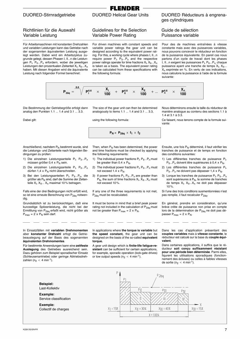
Richtlinien für die Auswahl Guidelines for the Selection Guide de sélectionVariable Leistung Variable Power Rating Puissance variable
Für Arbeitsmaschinen mit konstanten Drehzahlenund variablen Leistungen kann das Getriebe nachder sogenannten äquivalenten Leistung ausge-legt werden. Dabei wird ein Arbeitszyklus zu-grunde gelegt, dessen Phasen I, II...n die Leistun-gen PI, PII...Pn erfordern, wobei die jeweiligenLeistungen den prozentualen Zeitanteil XI, XII...Xnhaben. Mit diesen Angaben wird die äquivalenteLeistung nach folgender Formel berechnet:
For driven machines with constant speeds andvariable power ratings the gear unit can bedesigned according to the equivalent power rat-ing. For this, a working cycle where phases I, II...nrequire power PI, PII...Pn and the respectivepower ratings operate for time fractions XI, XII...Xnis taken as a basis. The equivalent power ratingcan be calculated from these specifications withthe following formula:
Pour des de machines entraînées à vitesseconstante mais avec des puissances variables,nous pouvons concevoir le réducteur en fonctionde la puissance équivalente. En pareil cas nouspartons d’un cycle de travail dont les phasesI, II...n exigent les puissances PI, PII...Pn, chaquepuissance ayant une tranche de temps XI, XII...Xn exprimée en %. En vertu de ces indications,nous calculons la puissance à l’aide de la formulesuivante:
P2äq � P6.6I �
XI
100� P6.6
II �XII
100� ��� P6.6
n �Xn
100
6.6
Die Bestimmung der Getriebegröße erfolgt dannanalog den Punkten 1.1 ... 1.4 und 3.1 ... 3.3.
Dabei gilt:
The size of the gear unit can then be determinedanalogously to items 1.1 ... 1.4 and 3.1 ... 3.3,
using the following formula:
Nous déterminons ensuite la taille du réducteur demanière analogue au contenu des sections 1.1 à1.4 et 3.1 à 3.3.
Ce faisant, nous tenons compte de la formule sui-vante:
PN ≥ P2äq � f1 � f2
Anschließend, nachdem PN bestimmt wurde, sinddie Leistungs- und Zeitanteile nach folgenden Be-dingungen zu prüfen:
1) Die einzelnen Leistungsanteile PI, PII...Pnmüssen größer 0,4 x PN sein.
2) Die einzelnen Leistungsanteile PI, PII...Pndürfen 1,4 x PN nicht überschreiten.
3) Bei den Leistungsanteilen PI, PII...Pn, diegrößer als PN sind, darf die Summe der Zeitan-teile XI, XII... Xn maximal 10 % betragen.
Falls eine der drei Bedingungen nicht erfüllt wird,so ist eine erneute Berechnung von P2äq notwen-dig.
Grundsätzlich ist zu berücksichtigen, daß einekurzzeitige Spitzenleistung, die nicht bei derErmittlung von P2äq erfaßt wird, nicht größer alsPmax = 2 x PN sein darf.
Then, when PN has been determined, the powerand time fractions must be checked by applyingthe following requirements:
1) The individual power fractions PI, PII...Pn mustbe greater than 0.4 x PN.
2) The individual power fractions PI, PII...Pn mustnot exceed 1.4 x PN.
3) If power fractions PI, PII...Pn are greater thanPN, the sum of time fractions XI, XII...Xn mustnot exceed 10 %.
If any one of the three requirements is not met,P2äq must be recalculated.
It must be borne in mind that a brief peak powerrating not included in the calculation of P2äq mustnot be greater than Pmax = 2 x PN.
Ensuite, une fois PN déterminé, il faut vérifier lestranches de puissance et de temps en fonctiondes conditions suivantes:
1) Les différentes tranches de puissance PI,PII...Pn doivent être supérieures à 0,4 x PN.
2) Les différentes tranches de puissance PI,PII...Pn ne doivent pas dépasser 1,4 x PN.
3) Lorque les tranches de puissance PI, PII...Pnsont supérieures à PN, la somme de tranchesde temps XI, XII...Xn ne doit pas dépasser10 %.
Si l’une des trois conditions susmentionnées n’estpas remplie, il faut recalculer P2äq.
En général, prendre en considération, qu’unebrève crête de puissance non prise en comptelors de la détermination de P2äq ne doit pas dé-passer Pmax = 2 x PN.
In Einsatzfällen mit variablen Drehmomentenaber konstanter Drehzahl erfogt die Getrie-beauslegung auf der Basis des sogenanntenäquivalenten Drehmomentes.
Für bestimmte Anwendungen kann eine zeitfesteAuslegung des Getriebes ausreichend sein.Dazu gehören zum Beispiel sporadischer Einsatz(Schleusenantriebe) oder geringe Abtriebsdreh-zahlen (n2 � 4 min-1).
In applications where the torque is variable butthe speed constant, the gear unit can bedesigned on the basis of the so-called equivalenttorque.A gear unit design which is finite-life fatigue-re-sistant can be sufficient for certain applications,for example, sporadic operation (lock-gate drives)or low output speeds (n2 � 4 min-1).
Dans les cas d’application présentant descouples variables mais à vitesse constante, leréducteur est calculé sur la base du couple équi-valent.Dans certaines applications, il suffira que le ré-ducteur soit conçu suffisamment résistantpour une période bien déterminée. Parmi elles,fiqurent les utilisations sporadiques (fonction-nement des écluses) ou celles à faibles vitessesde sortie (n2 � 4 min-1).
Beispiel:Last-Kollektiv
Example:Service classification
Exemple:Collectif de charges
K228 DE/EN/FR8
DUORED-Stirnradgetriebe DUORED Helical Gear Units DUORED Réducteurs à engrena-ges cylindriques
Erklärung der Bezeichnungen Key to Symbols Légende des symboles
Erklärung der Bezeichnungen:
ED = Einschaltdauer in % (z.B. ED = 80%je Stunde)
f1 = Arbeitsmaschinenfaktor (Tabelle 1),Seite 10
f2 = Antriebsmaschinenfaktor (Tabelle 2),Seite 10
f3 = Spitzenmomentfaktor (Tabelle 3),Seite 10
f4 = Wärmefaktor (Tabelle 4),Seite 10
f6 = Höhenfaktor (Tabelle 5),Seite 10
f14 = Auslastungsfaktor (Tabelle 6),Seite 10
i = Ist-Übersetzung
iN = Nennübersetzung
is = Soll-Übersetzung
n1 = Antriebsdrehzahl (min-1)
n2 = Abtriebsdrehzahl (min-1)
PG = Erforderliche Wärmegrenzleistung
PG1 = Wärmegrenzleistung für Getriebeohne Zusatzkühlung, Seite 16
PN = Getriebenennleistung (kW), sieheLeistungstabellen Seiten 13 - 15
P2 = Leistung der Arbeitsmaschine (kW)
t = Umgebungstemperatur (°C)
TA = Max. auftretendes Drehmoment anEingangswelle z.B.: Betriebsspitzen-,Anfahr- oder Bremsmoment (Nm)
T2N = Nenn-Abtriebsdrehmoment (kNm),Seite 17
Key to symbols:
ED = Operating cycle per hour in %,e.g. ED = 80% / h
f1 = Factor for driven machine (table 1),page 11
f2 = Factor for prime mover (table 2),page 11
f3 = Peak torque factor (table 3),page 11
f4 = Thermal factor (table 4),page 11
f6 = Factor for altitude (table 5),page 11
f14 = Utilization factor (table 6),page 11
i = Actual ratio
iN = Nominal ratio
is = Required ratio
n1 = Input speed (min-1)
n2 = Output speed (min-1)
PG = Required thermal capacity
PG1 = Thermal capacity for gear unitswithout auxiliary cooling, page 16
PN = Nominal power rating of gear unit(kW), see rating tables, pages 13 - 15
P2 = Power rating of driven machine (kW)
t = Ambient temperature (°C)
TA = Max. torque occurring on input shaft,e.g. peak operating-, starting- orbraking torque (Nm)
T2N = Nominal output torque (kNm),page 17
Légende des symboles:
ED = Durée d’utilisation en %, par ex:(ED = 80% par heure)
f1 = Facteur de travail des machines(tableau 1), page 12
f2 = Facteur des machines motrices(tableau 2), page 12
f3 = Facteur des pointes maximales(tableau 3), page 12
f4 = Facteur thermique (tableau 4),page 12
f6 = Facteur d’altitude (tableau 5),page 12
f14 = Facteur d’utilisation (tableau 6),page 12
i = Rapports réels
iN = Rapports nominaux
is = Rapports théoriques
n1 = Vitesse d’entrée (1/min)
n2 = Vitesse de sortie (1/min)
PG = Capacité thermique nécessaire
PG1 = Capacité thermique limite sanssystème de refroidissement complé-mentaire, page 16
PN = Puissance nominale du réducteur(kW); voir tableau de puissance,pages 13 - 15
P2 = Puissance de la machine receptrice(kW)
t = Température ambiante (°C)
TA = Couple maximal à l’arbre d’entrée; parex: pointes de fonctionnement, couplede freinage ou de démarrage (Nm)
T2N = Couple nominal de sortie (kNm),page 17
P2äq = äquivalente Leistung (kW)
PI, PII, Pn= Leistungsanteile (kW) aus
Lastkollektiv
XI, XII, Xn= Zeitanteile (%) aus Lastkollektiv
P2äq = Equivalent power rating (kW)
PI, PII, Pn= Fractions of power rating (kW) obtain-
ed from service classification
XI, XII, Xn= Fractions of time (%) obtained from
service classification
P2äq = Puissance équivalente (kW)
PI, PII, Pn= Tranches de puissance (kW) d’un
collectif de charges
XI, XII, Xn= Tranches de temps (%) d’un collectif de
charges
9K228 DE/EN/FR
DUORED-Stirnradgetriebe DUORED Helical Gear Units DUORED Réducteurs à engrena-ges cylindriques
Richtlinien für die Auswahl Guidelines for the Selection Guide de sélectionBerechnungsbeispiel Calculation Example Exemples de calcul
Gegeben:
ANTRIEBSMASCHINE
Elektromotor P1 = 1250 kW
Motordrehzahl n1 = 750 min-1
Max. Anfahrmoment TA = 24 000 Nm
ARBEITSMASCHINE
Rohrmühle (Zement) P2 = 1200 kW
Drehzahl n2 = 19 min-1
Betriebsdauer 16 h / Tag
Anläufe je Stunde 5
Einschaltdauerje Stunde ED = 100%
Umgebungstemperatur 50 °CAufstellung im Freien (w ≥ 4 m/s)
Höhenlage Meereshöhe
GETRIEBEAUSFÜHRUNG
Stirnradgetriebe
Einbau horizontal
Abtriebswelle d2 rechts, Ausführung B
Drehrichtung derAbtriebswelle d2 links
Gesucht:Getriebebauart, Getriebegröße
1. Bestimmung der Getriebebauart undGröße
1.1 Bestimmung der Übersetzungen
Known criteria:
PRIME MOVER
Electric motor P1 = 1250 kW
Motor speed n1 = 750 min-1
Max. starting torque TA = 24 000 Nm
DRIVEN MACHINE
Tube mill (Cement) P2 = 1200 kW
Speed n2 = 19 min-1
Duty 16 h / day
Starts per hour 5
Operating cycleper hour ED = 100%Ambienttemperature 50 °COutdoor installation (w ≥ 4 m/s)
Altitude sea level
GEAR UNIT DESIGN
Helical gear unit
Mounting position horizontal
Output shaft d2 on right hand side,design B
Direction of rotationof output shaft d2 ccw
Required:Type and size of gear unit
1. Selection of gear unit type and size
1.1 Calculation of transmission ratios
Données:
MACHINE MOTRICE
Moteur électrique P1 = 1250 kW
Vitesse du moteur n1 = 750 min-1
Couple de démarrage max. TA = 24 000 Nm
MACHINE DE TRAVAIL
Tubes broyeurs (Ciment) P2 = 1200 kW
Vitesse n2 = 19 min-1
Durée de fonctionnement 16 h / jour
Nombre de démarragespar heure 5
Durée d’utilisationhoraire ED = 100%Températureambiante 50 °CInstallation à l’extérieur (w ≥ 4 m/s)
Altitude niveau de la mer
EXECUTION DU REDUCTEUR
Réducteur à engrenages cylindriques
Montage horizontal
Arbre de sortie d2 droite, Exécution B
Sens de rotation del’arbre de sortie d2 à gauche
On recherche:La taille et le type du réducteur
1. Détermination de la taille et du type duréducteur
1.1 Détermination du rapport
is =n1n2
= 75019
= 39.5 iN = 40
1.2 Bestimmung der Getriebenennleistung 1.2 Determination of the gear unit nominal powerrating
1.2 Détermination de la puissance nominaledu réducteur
PN ≥ P2 x f1 x f2 = 1200 x 2.0 x 1 = 2400 kW
Aus Leistungstabelle Bauart SDNL, Getriebe-größe 750 mit PN = 2720 kW gewählt.
Selected from power rating table: type SDNL, gearunit size 750, with PN = 2720 kW
Sélectionné sur le tableau de puissance: typeSDNL, taille 750 avec PN = 2720 kW
3.33 x P2 ≥ PN 3.33 x 1200 = 3996 kW > PNRücksprache nicht erforderlichIt is not necessary to consult usLa consultation n’est pas nécessaire
1.3 Kontrolle auf Anfahrmoment 1.3 Checking the starting torque 1.3 Contrôle du couple de démarrage
PN ≥TA x n1
9550x f3 =
24000 x 750
9550x 0.5 = 942.4 kW PN = 2720 kW > 942.4 kW
2. Bestimmung der Wärmegrenzleistung
2.1 Getriebeauslastung
2. Determination of thermal capacity
2.1 Gear unit utilization
2. Détermination de la capacité thermiquelimite
2.1 Taux d’utilisation du réducteur
Auslastung / Utilization /Taux d’utilisation in / en % x 100 =
1200 kW
2720 kWx 100 = 44%
P2
PN=
2.1 Wärmegrenzleistung aus Tabelle BauartSDNL (siehe Seite 16)
2.1 Thermal capacity acc. to table for type SDNL(see page 16)
2.1 Capacité thermique selon tableau pour typeSDNL (voir page 16)
P2 ≥ PG = PG1 x f4 x f6 x f14 = 905 kW x 0.55 x 1.0 x 0.77 = 383 kW P2 = 1200 kW > PG = 383 kW
Zusatzkühlung und somit Rücksprache erforderlich! / Auxiliary cooling is necessary! Please refer to us!Refroidissement supplémentaire et donc consultation nécessaire!
K228 DE/EN/FR10
DUORED-Stirnradgetriebe
Betriebsfaktoren
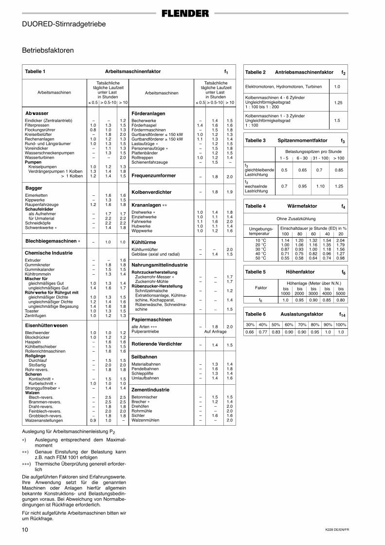
Tabelle 1 Arbeitsmaschinenfaktor f1
Arbeitsmaschinen
> 10
Arbeitsmaschinen
Tatsächliche tägliche Laufzeit unter Last in Stunden
AbwasserEindicker (Zentralantrieb)FilterpressenFlockungsrührerKreiselbelüfterRechenanlagenRund- und LängsräumerVoreindickerWasserschneckenpumpenWasserturbinenPumpen Kreiselpumpen Verdrängerpumpen 1 Kolben > 1 Kolben
–1.00.8 –1.01.0 – – –
1.01.31.2
–1.31.01.81.21.31.11.3 –
1.21.41.4
1.21.51.32.01.31.51.31.52.0
1.31.81.5
BaggerEimerkettenKippwerkeRaupenfahrzeugeSchaufelräder als Aufnehmer für UrmaterialSchneidköpfeSchwenkwerke ∗
– –1.2 – – – –
1.61.31.6
1.72.22.21.4
1.61.51.8
1.72.22.21.8
Blechbiegemaschinen ∗ – 1.0 1.0
Chemische IndustrieExtruderGummikneterGummikalanderKühltrommelnMischer für gleichmäßiges Gut ungleichmäßiges GutRührwerke für Rührgut mit gleichmäßiger Dichte ungleichmäßiger Dichte ungleichmäßige BegasungToasterZentrifugen
– – – –
1.01.4
1.01.21.41.01.0
–1.81.51.3
1.31.6
1.31.41.61.31.2
1.61.81.51.4
1.41.7
1.51.61.81.51.3
EisenhüttenwesenBlechwenderBlockdrückerHaspelnKühlbettschieberRollenrichtmaschinenRollgänge Durchlauf StoßartigRohr-revers.Scheren Kontischnitt ∗ Kurbelschnitt ∗Stranggußtreiber ∗Walzen Blech-revers. Brammen-revers. Draht-revers. Feinblech-revers. Grobblech-revers.Walzenanstellungen
1.01.0 – – –
– – –
–1.0 –
– – – – –0.9
1.01.21.61.51.6
1.52.01.8
1.51.01.4
2.52.51.82.01.81.0
1.21.21.61.51.6
1.52.01.8
1.51.01.4
2.52.51.82.01.8 –
BecherwerkeFörderhaspelFörderrmaschinenGurtbandförderer ≤ 150 kWGurtbandförderer ≥ 150 kWLastaufzüge ∗Personenaufzüge ∗PlattenbänderRolltreppenSchienenfahrzeuge
–1.4 –1.01.1 – – –1.0 –
1.41.61.51.21.31.21.51.21.21.5
1.51.61.81.31.41.51.81.51.4 –
Förderanlagen
Frequenzumformer – 1.8 2.0
Kolbenverdichter 1.8 1.9
Krananlagen ∗∗Drehwerke ∗EinziehwerkeFahrwerkeHubwerkeWippwerke
1.01.01.11.01.0
1.41.11.61.11.2
1.81.42.01.41.6
KühltürmeKühlturmlüfterGebläse (axial und radial)
– –
–1.4
2.01.5
NahrungsmittelindustrieRohrzuckerherstellung Zuckerrohr-Messer ∗ Zuckerrohr-MühleRübenzucker-Herstellung Schnitzelmaische Extraktionsanlage, Kühlma- schine, Kochapparat, Rübenwäsche, Schneidma- schine
– –
–
–
–
– –
–
–
–
1.71.7
1.2
1.4
1.5
Papiermaschinenalle Arten ∗∗∗ – 1.8 2.0
Rotierende Verdichter 1.4 1.5 –
SeilbahnenMaterialbahnenPendelbahnenSchlepplifte Umlaufbahnen
– – – –
1.31.61.31.4
1.41.81.41.6
ZementindustrieBetonmischerBrecher ∗DrehöfenRohrmühleSichterWalzenmühlen
– – – – – –
1.51.2 – –1.6 –
1.51.42.02.01.62.0
Tabelle 2 Antriebsmaschinenfaktor f2
Elektromotoren, Hydromotoren, Turbinen
Kolbenmaschinen 4 - 6 ZylinderUngleichförmigkeitsgrad1 : 100 bis 1 : 200
Kolbenmaschinen 1 - 3 ZylinderUngleichförmigkeitsgrad1 : 100
1.0
1.25
1.5
Tabelle 3 Spitzenmomentfaktor f3
Belastungsspitzen pro Stunde
1 - 5 6 - 30 31 - 100 > 100
f3gleichbleibendeLastrichtung
f3wechselndeLastrichtung
0.5 0.65 0.7 0.85
1.10 1.250.7 0.95
Tabelle 4 Wärmefaktor f4
–
≤ 0.5 > 0.5-10 > 10≤ 0.5 > 0.5-10
Tatsächliche tägliche Laufzeit unter Last in Stunden
Auf AnfragePulperantriebe
Ohne Zusatzkühlung
Umgebungs-temperatur
10 °C20 °C30 °C40 °C50 °C
Einschaltdauer je Stunde (ED) in %
1.141.000.870.710.55
1.201.060.930.750.58
1.321.161.000.820.64
1.541.351.180.960.74
2.041.791.561.270.98
100 80 60 40 20
Tabelle 5 Höhenfaktor f6
Tabelle 6 Auslastungsfaktor f14
FaktorHöhenlage (Meter über N.N.)
bis1000
bis2000
bis3000
bis4000
bis5000
f6 1.0 0.95 0.90 0.85 0.80
0.83
50%
0.66
30%
0.77
40%
0.90
60%
0.90
70%
0.95
80%
1.0
90%
1.0
100%
Auslegung für Arbeitsmaschinenleistung P2
∗) Auslegung entsprechend dem Maximal-moment
∗∗) Genaue Einstufung der Belastung kannz.B. nach FEM 1001 erfolgen
∗∗∗) Thermische Überprüfung generell erforder-lich
Die aufgeführten Faktoren sind Erfahrungswerte.Ihre Anwendung setzt für die genanntenMaschinen oder Anlagen hierfür allgemeinbekannte Konstruktions- und Belastungsbedin-gungen voraus. Bei Abweichung von Normalbe-dingungen ist Rückfrage erforderlich.
Für nicht aufgeführte Arbeitsmaschinen bitten wirum Rückfrage.
11K228 DE/EN/FR
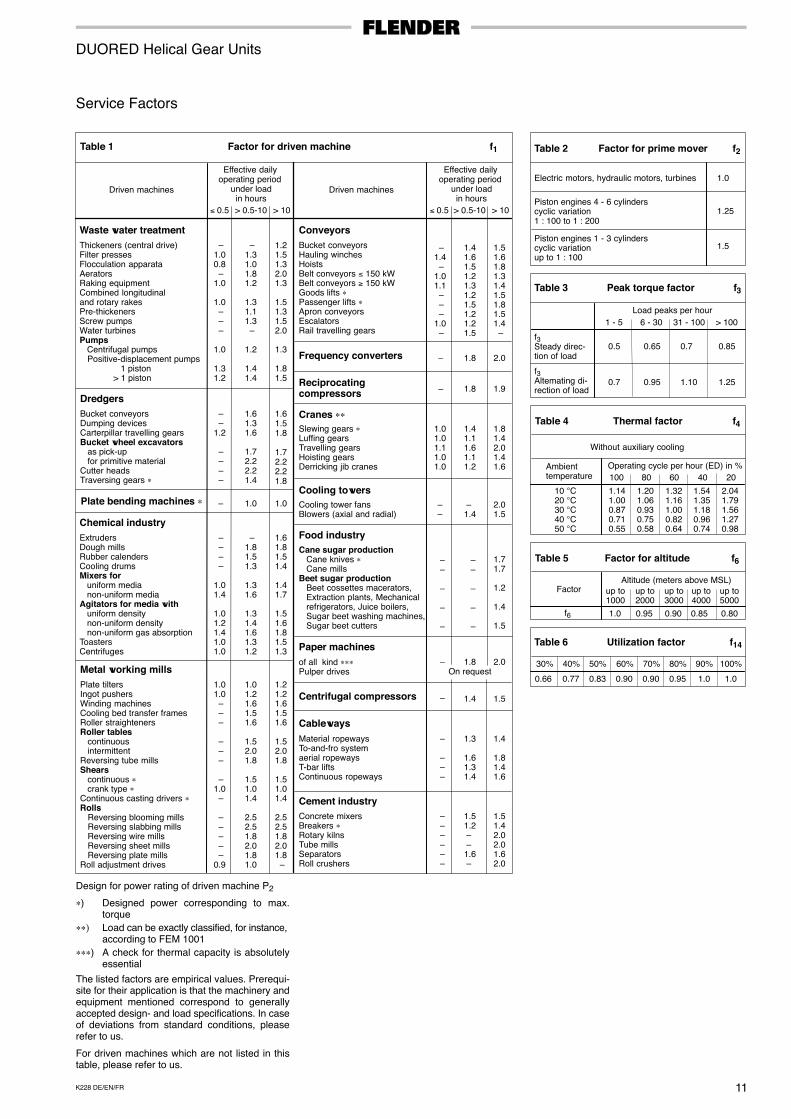
DUORED Helical Gear Units
Service Factors
Table 1 Factor for driven machine f1
Driven machines
> 10
Waste water treatmentThickeners (central drive)Filter pressesFlocculation apparataAeratorsRaking equipmentCombined longitudinaland rotary rakesPre-thickenersScrew pumpsWater turbinesPumps Centrifugal pumps Positive-displacement pumps 1 piston > 1 piston
–1.00.8 –1.0
1.0 – – –
1.0
1.31.2
–1.31.01.81.2
1.31.11.3 –
1.2
1.41.4
1.21.51.32.01.3
1.51.31.52.0
1.3
1.81.5
DredgersBucket conveyorsDumping devicesCarterpillar travelling gearsBucket wheel excavators as pick-up for primitive materialCutter headsTraversing gears ∗
– –1.2 – – – –
1.61.31.6
1.72.22.21.4
1.61.51.8
1.72.22.21.8
Plate bending machines ∗ – 1.0 1.0
Chemical industryExtrudersDough millsRubber calendersCooling drumsMixers for uniform media non-uniform mediaAgitators for media with uniform density non-uniform density non-uniform gas absorptionToastersCentrifuges
– – – –
1.01.4
1.01.21.41.01.0
–1.81.51.3
1.31.6
1.31.41.61.31.2
1.61.81.51.4
1.41.7
1.51.61.81.51.3
Metal working millsPlate tiltersIngot pushersWinding machinesCooling bed transfer framesRoller straightenersRoller tables continuous intermittentReversing tube millsShears continuous ∗ crank type ∗Continuous casting drivers ∗Rolls Reversing blooming mills Reversing slabbing mills Reversing wire mills Reversing sheet mills Reversing plate millsRoll adjustment drives
1.01.0 – – –
– – –
–1.0 –
– – – – –0.9
1.01.21.61.51.6
1.52.01.8
1.51.01.4
2.52.51.82.01.81.0
1.21.21.61.51.6
1.52.01.8
1.51.01.4
2.52.51.82.01.8 –
Bucket conveyorsHauling winchesHoistsBelt conveyors ≤ 150 kWBelt conveyors ≥ 150 kWGoods lifts ∗Passenger lifts ∗Apron conveyorsEscalatorsRail travelling gears
–1.4 –1.01.1 – – –1.0 –
1.41.61.51.21.31.21.51.21.21.5
1.51.61.81.31.41.51.81.51.4 –
Conveyors
Frequency converters – 1.8 2.0
Reciprocatingcompressors 1.8 1.9
Cranes ∗∗Slewing gears ∗Luffing gearsTravelling gearsHoisting gearsDerricking jib cranes
1.01.01.11.01.0
1.41.11.61.11.2
1.81.42.01.41.6
Cooling towersCooling tower fansBlowers (axial and radial)
– –
–1.4
2.01.5
Food industryCane sugar production
Cane knives ∗Cane mills
Beet sugar productionBeet cossettes macerators,Extraction plants, Mechanicalrefrigerators, Juice boilers,Sugar beet washing machines,Sugar beet cutters
– –
–
–
–
– –
–
–
–
1.71.7
1.2
1.4
1.5
Paper machinesof all kind ∗∗∗Pulper drives
– 1.8 2.0
Centrifugal compressors 1.4 1.5 –
CablewaysMaterial ropewaysTo-and-fro systemaerial ropewaysT-bar liftsContinuous ropeways
–
– – –
1.3
1.61.31.4
1.4
1.81.41.6
Cement industryConcrete mixersBreakers ∗Rotary kilnsTube millsSeparatorsRoll crushers
– – – – – –
1.51.2 – –1.6 –
1.51.42.02.01.62.0
–
> 0.5-10 > 10≤ 0.5 > 0.5-10
Effective dailyoperating period under load in hours
Effective dailyoperating period under load in hours
≤ 0.5
Driven machines
Table 2 Factor for prime mover f2
Electric motors, hydraulic motors, turbines
Piston engines 4 - 6 cylinderscyclic variation1 : 100 to 1 : 200
Piston engines 1 - 3 cylinderscyclic variationup to 1 : 100
1.0
1.25
1.5
Table 3 Peak torque factor f3
Load peaks per hour
1 - 5 6 - 30 31 - 100 > 100
f3Steady direc-tion of load
f3Altemating di-rection of load
0.5 0.65 0.7 0.85
1.10 1.250.7 0.95
Table 4 Thermal factor f4
Without auxiliary cooling
Ambienttemperature
10 °C20 °C30 °C40 °C50 °C
Operating cycle per hour (ED) in %
1.141.000.870.710.55
1.201.060.930.750.58
1.321.161.000.820.64
1.541.351.180.960.74
2.041.791.561.270.98
100 80 60 40 20
Table 5 Factor for altitude f6
FactorAltitude (meters above MSL)
up to1000
up to2000
up to3000
up to4000
up to5000
f6 1.0 0.95 0.90 0.85 0.80
On request
Table 6 Utilization factor f14
0.83
50%
0.66
30%
0.77
40%
0.90
60%
0.90
70%
0.95
80%
1.0
90%
1.0
100%
Design for power rating of driven machine P2
∗) Designed power corresponding to max.torque
∗∗) Load can be exactly classified, for instance, according to FEM 1001
∗∗∗) A check for thermal capacity is absolutelyessential
The listed factors are empirical values. Prerequi-site for their application is that the machinery andequipment mentioned correspond to generallyaccepted design- and load specifications. In caseof deviations from standard conditions, pleaserefer to us.
For driven machines which are not listed in thistable, please refer to us.
K228 DE/EN/FR12
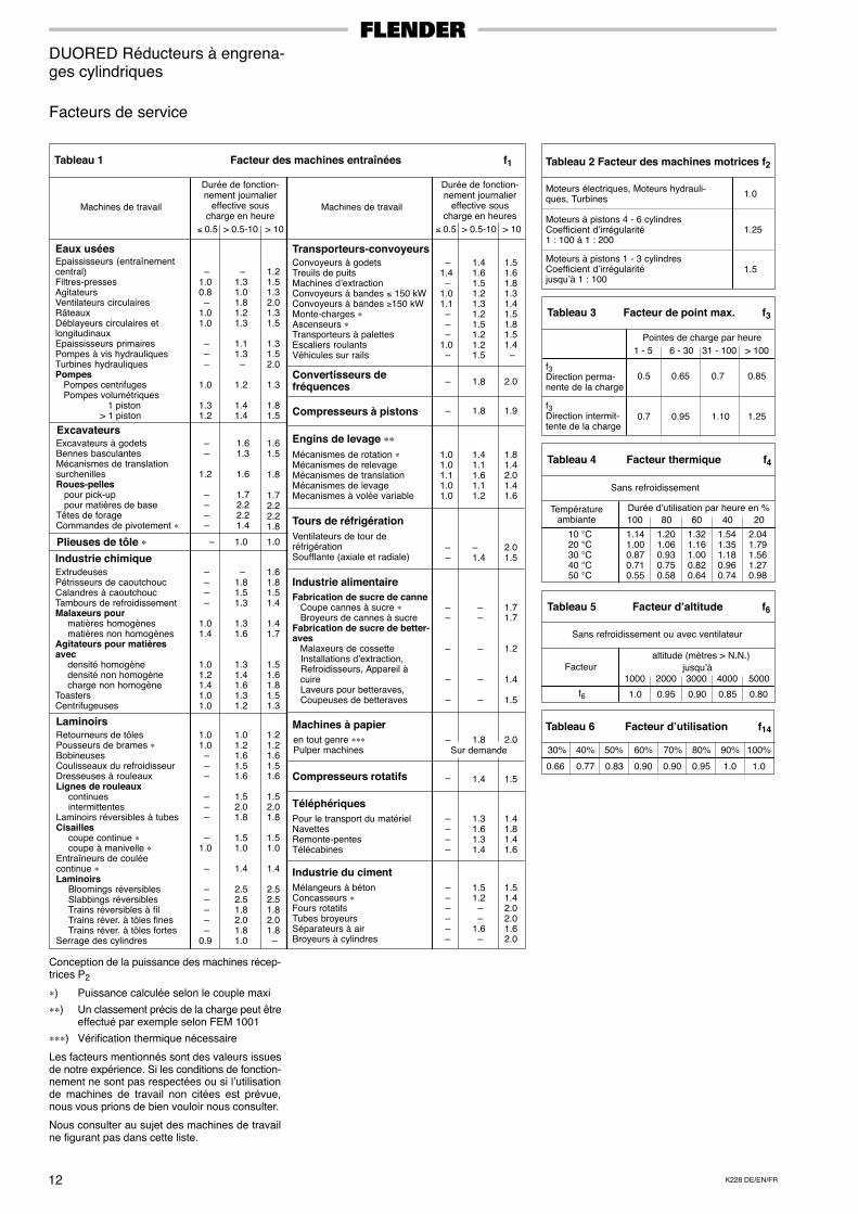
DUORED Réducteurs à engrena-ges cylindriques
Facteurs de service
Tableau 1 Facteur des machines entraînées f1
Machines de travail
> 10
Eaux uséesEpaississeurs (entraînementcentral)Filtres-pressesAgitateursVentilateurs circulairesRâteauxDéblayeurs circulaires etlongitudinauxEpaississeurs primairesPompes à vis hydrauliquesTurbines hydrauliquesPompes Pompes centrifuges Pompes volumétriques 1 piston > 1 piston
–1.00.8 –1.01.0
– – –
1.0
1.31.2
–1.31.01.81.21.3
1.11.3 –
1.2
1.41.4
1.21.51.32.01.31.5
1.31.52.0
1.3
1.81.5
ExcavateursExcavateurs à godetsBennes basculantesMécanismes de translationsurchenillesRoues-pelles pour pick-up pour matières de baseTêtes de forageCommandes de pivotement ∗
– –
1.2 – – – –
1.61.3
1.6
1.72.22.21.4
1.61.5
1.8
1.72.22.21.8
Plieuses de tôle ∗ – 1.0 1.0
Industrie chimiqueExtrudeusesPétrisseurs de caoutchoucCalandres à caoutchoucTambours de refroidissementMalaxeurs pour
matières homogènesmatières non homogènes
Agitateurs pour matièresavec
densité homogènedensité non homogènecharge non homogène
ToastersCentrifugeuses
– – – –
1.01.4
1.01.21.41.01.0
–1.81.51.3
1.31.6
1.31.41.61.31.2
1.61.81.51.4
1.41.7
1.51.61.81.51.3
LaminoirsRetourneurs de tôlesPousseurs de brames ∗BobineusesCoulisseaux du refroidisseurDresseuses à rouleauxLignes de rouleaux
continuesintermittentes
Laminoirs réversibles à tubesCisailles
coupe continue ∗coupe à manivelle ∗
Entraîneurs de couléecontinue ∗Laminoirs
Bloomings réversiblesSlabbings réversiblesTrains réversibles à filTrains réver. à tôles finesTrains réver. à tôles fortes
Serrage des cylindres
1.01.0 – – – – – –
–1.0
–
– – – – –0.9
1.01.21.61.51.6
1.52.01.8
1.51.0
1.4
2.52.51.82.01.81.0
1.21.21.61.51.6
1.52.01.8
1.51.0
1.4
2.52.51.82.01.8 –
Convoyeurs à godetsTreuils de puitsMachines d’extraction Convoyeurs à bandes ≤ 150 kWConvoyeurs à bandes ≥150 kWMonte-charges ∗Ascenseurs ∗Transporteurs à palettesEscaliers roulantsVéhicules sur rails
–1.4 –1.01.1 – – –1.0 –
1.41.61.51.21.31.21.51.21.21.5
1.51.61.81.31.41.51.81.51.4 –
Transporteurs-convoyeurs
Convertisseurs defréquences – 1.8 2.0
Compresseurs à pistons 1.8 1.9
Engins de levage ∗∗Mécanismes de rotation ∗Mécanismes de relevageMécanismes de translationMécanismes de levageMecanismes à volée variable
1.01.01.11.01.0
1.41.11.61.11.2
1.81.42.01.41.6
Tours de réfrigérationVentilateurs de tour deréfrigérationSoufflante (axiale et radiale)
– –
–1.4
2.01.5
Industrie alimentaireFabrication de sucre de canne Coupe cannes à sucre ∗ Broyeurs de cannes à sucreFabrication de sucre de better-aves Malaxeurs de cossette Installations d’extraction, Refroidisseurs, Appareil à cuire Laveurs pour betteraves, Coupeuses de betteraves
– –
–
–
–
– –
–
–
–
1.71.7
1.2
1.4
1.5
Machines à papieren tout genre ∗∗∗Pulper machines
– 1.8 2.0
Compresseurs rotatifs 1.4 1.5 –
TéléphériquesPour le transport du matériel NavettesRemonte-pentesTélécabines
– – – –
1.31.61.31.4
1.41.81.41.6
Industrie du cimentMélangeurs à bétonConcasseurs ∗Fours rotatifsTubes broyeursSéparateurs à airBroyeurs à cylindres
– – – – – –
1.51.2 – –1.6 –
1.51.42.02.01.62.0
–
≤ 0.5 > 0.5-10 > 10≤ 0.5 > 0.5-10
Durée de fonction-nement journalier
effective souscharge en heure
Machines de travail
Durée de fonction-nement journalier
effective souscharge en heures
Tableau 2 Facteur des machines motrices f2
Moteurs électriques, Moteurs hydrauli-ques, Turbines
Moteurs à pistons 4 - 6 cylindresCoefficient d’irrégularité1 : 100 à 1 : 200
Moteurs à pistons 1 - 3 cylindresCoefficient d’irrégularitéjusqu’à 1 : 100
1.0
1.25
1.5
Tableau 3 Facteur de point max. f3
Pointes de charge par heure
1 - 5 6 - 30 31 - 100 > 100
f3Direction perma-nente de la charge
f3Direction intermit-tente de la charge
0.5 0.65 0.7 0.85
1.10 1.250.7 0.95
Tableau 4 Facteur thermique f4
Sans refroidissement
Températureambiante
10 °C20 °C30 °C40 °C50 °C
Durée d’utilisation par heure en %
1.141.000.870.710.55
1.201.060.930.750.58
1.321.161.000.820.64
1.541.351.180.960.74
2.041.791.561.270.98
100 80 60 40 20
Tableau 5 Facteur d’altitude f6
Sans refroidissement ou avec ventilateur
altitude (mètres > N.N.)
1000 2000 3000 4000 5000
f6 1.0 0.95 0.90 0.85 0.80
Sur demande
Facteur jusqu’à
Tableau 6 Facteur d’utilisation f14
0.83
50%
0.66
30%
0.77
40%
0.90
60%
0.90
70%
0.95
80%
1.0
90%
1.0
100%
Conception de la puissance des machines récep-trices P2
∗) Puissance calculée selon le couple maxi
∗∗) Un classement précis de la charge peut êtreeffectué par exemple selon FEM 1001
∗∗∗) Vérification thermique nécessaire
Les facteurs mentionnés sont des valeurs issuesde notre expérience. Si les conditions de fonction-nement ne sont pas respectées ou si l’utilisationde machines de travail non citées est prévue,nous vous prions de bien vouloir nous consulter.
Nous consulter au sujet des machines de travailne figurant pas dans cette liste.
13K228 DE/EN/FR
DUORED-Stirnradgetriebe DUORED Helical Gear Units DUORED Réducteurs à engrena-ges cylindriques
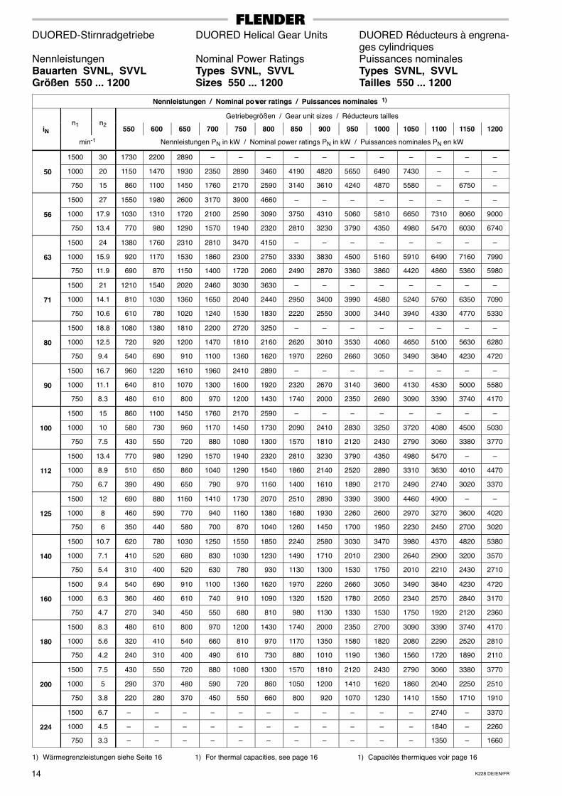
Nennleistungen Nominal Power Ratings Puissances nominalesBauarten SDNL, SDVL Types SDNL, SDVL Types SDNL, SDVLGrößen 550 ... 1200 Sizes 550 ... 1200 Tailles 550 ... 1200
Nennleistungen / Nominal power ratings / Puissances nominales 1)
n nGetriebegrößen / Gear unit sizes / Réducteurs tailles
iNn1 n2
550 600 650 700 750 800 850 900 950 1000 1050 1100 1150 1200N
min-1 Nennleistungen PN in kW / Nominal power ratings PN in kW / Puissances nominales PN en kW
1500 83 – – – – – – – – – – – – – –
18 1000 56 3230 4100 5390 6570 – – – – – – – – – –
750 42 2420 3080 4050 4930 6070 7260 – – – – – – – –
1500 75 – – – – – – – – – –A f Anfrage
–
20 1000 50 2880 3660 4820 5860 7230 – – – – –Auf AnfrageOn request
S d d–
750 38 2190 2790 3660 4460 5490 6570 – – – –
qSur demande
–
1500 67 – – – – – – – – – – – – – –
22.4 1000 45 2590 3300 4340 5280 6500 – – – – – – – – –
750 33 1900 2420 3180 3870 4770 5700 6910 7950 9330 – – – – –
1500 60 3460 – – – – – – – – – – – – –
25 1000 40 2300 2930 3850 4690 5780 6910 – – – – – – – –
750 30 1730 2200 2890 3520 4340 5180 6280 7230 8480 9740 – – – –
1500 54 3110 – – – – – – – – – – – – –
28 1000 36 2070 2640 3470 4220 5200 6220 – – – – – – – –
750 27 1550 1980 2600 3170 3900 4660 5650 6500 7630 8760 – – – –
1500 48 2760 3520 4620 – – – – – – – – – – –
31.5 1000 32 1840 2350 3080 3750 4620 5530 6700 7710 9050 – – – – –
750 24 1380 1760 2310 2810 3470 4150 5030 5780 6790 7790 – – – –
1500 42 2420 3080 4050 – – – – – – – – – – –
35.5 1000 28 1610 2050 2700 3280 4050 4840 5860 6740 7920 – – – – –
750 21 1210 1540 2020 2460 3030 3630 4400 5060 5940 6820 7810 – – –
1500 38 2190 2790 3660 – – – – – – – – – – –
40 1000 25 1440 1830 2410 2930 3610 4320 5240 6020 7070 – – – – –
750 18.8 1080 1380 1810 2200 2720 3250 3940 4530 5320 6100 6990 7680 8460 –
1500 33 1900 2420 3180 – – – – – – – – – – –
45 1000 22 1270 1610 2120 2580 3180 3800 4610 5300 6220 – – – – –
750 16.7 960 1220 1610 1960 2410 2890 3500 4020 4720 5420 6210 6820 7520 8390
1500 30 – – – – – – – – – – – – – –
50 1000 20 – – – – – – – – – – – – – –
750 15 – – – – – – – – – – – 6120 – 7540
1) Wärmegrenzleistungen siehe Seite 16
Auf Anfrage (Einschränkung der Wälz-lagerlebensdauer)
1) For thermal capacities, see page 16
On request (limited service life of rollingbearings)
1) Capacités thermiques voir page 16
Sur demande (durée de vie des roule-ments limitée
K228 DE/EN/FR14
DUORED-Stirnradgetriebe DUORED Helical Gear Units DUORED Réducteurs à engrena-ges cylindriques
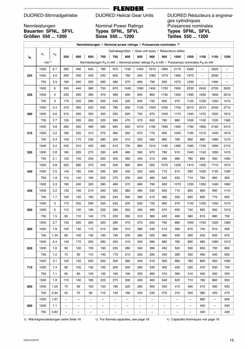
Nennleistungen Nominal Power Ratings Puissances nominalesBauarten SVNL, SVVL Types SVNL, SVVL Types SVNL, SVVLGrößen 550 ... 1200 Sizes 550 ... 1200 Tailles 550 ... 1200
Nennleistungen / Nominal power ratings / Puissances nominales 1)
n nGetriebegrößen / Gear unit sizes / Réducteurs tailles
iNn1 n2
550 600 650 700 750 800 850 900 950 1000 1050 1100 1150 1200N
min-1 Nennleistungen PN in kW / Nominal power ratings PN in kW / Puissances nominales PN en kW
1500 30 1730 2200 2890 – – – – – – – – – – –
50 1000 20 1150 1470 1930 2350 2890 3460 4190 4820 5650 6490 7430 – – –
750 15 860 1100 1450 1760 2170 2590 3140 3610 4240 4870 5580 – 6750 –
1500 27 1550 1980 2600 3170 3900 4660 – – – – – – – –
56 1000 17.9 1030 1310 1720 2100 2590 3090 3750 4310 5060 5810 6650 7310 8060 9000
750 13.4 770 980 1290 1570 1940 2320 2810 3230 3790 4350 4980 5470 6030 6740
1500 24 1380 1760 2310 2810 3470 4150 – – – – – – – –
63 1000 15.9 920 1170 1530 1860 2300 2750 3330 3830 4500 5160 5910 6490 7160 7990
750 11.9 690 870 1150 1400 1720 2060 2490 2870 3360 3860 4420 4860 5360 5980
1500 21 1210 1540 2020 2460 3030 3630 – – – – – – – –
71 1000 14.1 810 1030 1360 1650 2040 2440 2950 3400 3990 4580 5240 5760 6350 7090
750 10.6 610 780 1020 1240 1530 1830 2220 2550 3000 3440 3940 4330 4770 5330
1500 18.8 1080 1380 1810 2200 2720 3250 – – – – – – – –
80 1000 12.5 720 920 1200 1470 1810 2160 2620 3010 3530 4060 4650 5100 5630 6280
750 9.4 540 690 910 1100 1360 1620 1970 2260 2660 3050 3490 3840 4230 4720
1500 16.7 960 1220 1610 1960 2410 2890 – – – – – – – –
90 1000 11.1 640 810 1070 1300 1600 1920 2320 2670 3140 3600 4130 4530 5000 5580
750 8.3 480 610 800 970 1200 1430 1740 2000 2350 2690 3090 3390 3740 4170
1500 15 860 1100 1450 1760 2170 2590 – – – – – – – –
100 1000 10 580 730 960 1170 1450 1730 2090 2410 2830 3250 3720 4080 4500 5030
750 7.5 430 550 720 880 1080 1300 1570 1810 2120 2430 2790 3060 3380 3770
1500 13.4 770 980 1290 1570 1940 2320 2810 3230 3790 4350 4980 5470 – –
112 1000 8.9 510 650 860 1040 1290 1540 1860 2140 2520 2890 3310 3630 4010 4470
750 6.7 390 490 650 790 970 1160 1400 1610 1890 2170 2490 2740 3020 3370
1500 12 690 880 1160 1410 1730 2070 2510 2890 3390 3900 4460 4900 – –
125 1000 8 460 590 770 940 1160 1380 1680 1930 2260 2600 2970 3270 3600 4020
750 6 350 440 580 700 870 1040 1260 1450 1700 1950 2230 2450 2700 3020
1500 10.7 620 780 1030 1250 1550 1850 2240 2580 3030 3470 3980 4370 4820 5380
140 1000 7.1 410 520 680 830 1030 1230 1490 1710 2010 2300 2640 2900 3200 3570
750 5.4 310 400 520 630 780 930 1130 1300 1530 1750 2010 2210 2430 2710
1500 9.4 540 690 910 1100 1360 1620 1970 2260 2660 3050 3490 3840 4230 4720
160 1000 6.3 360 460 610 740 910 1090 1320 1520 1780 2050 2340 2570 2840 3170
750 4.7 270 340 450 550 680 810 980 1130 1330 1530 1750 1920 2120 2360
1500 8.3 480 610 800 970 1200 1430 1740 2000 2350 2700 3090 3390 3740 4170
180 1000 5.6 320 410 540 660 810 970 1170 1350 1580 1820 2080 2290 2520 2810
750 4.2 240 310 400 490 610 730 880 1010 1190 1360 1560 1720 1890 2110
1500 7.5 430 550 720 880 1080 1300 1570 1810 2120 2430 2790 3060 3380 3770
200 1000 5 290 370 480 590 720 860 1050 1200 1410 1620 1860 2040 2250 2510
750 3.8 220 280 370 450 550 660 800 920 1070 1230 1410 1550 1710 1910
1500 6.7 – – – – – – – – – – – 2740 – 3370
224 1000 4.5 – – – – – – – – – – – 1840 – 2260
750 3.3 – – – – – – – – – – – 1350 – 1660
1) Wärmegrenzleistungen siehe Seite 16 1) For thermal capacities, see page 16 1) Capacités thermiques voir page 16
15K228 DE/EN/FR
DUORED-Stirnradgetriebe DUORED Helical Gear Units DUORED Réducteurs à engrena-ges cylindriques
Nennleistungen Nominal Power Ratings Puissances nominalesBauarten SFNL, SFVL Types SFNL, SFVL Types SFNL, SFVLGrößen 550 ... 1200 Sizes 550 ... 1200 Tailles 550 ... 1200
Nennleistungen / Nominal power ratings / Puissances nominales 1)
n nGetriebegrößen / Gear unit sizes / Réducteurs tailles
iNn1 n2
550 600 650 700 750 800 850 900 950 1000 1050 1100 1150 1200N
min-1 Nennleistungen PN in kW / Nominal power ratings PN in kW / Puissances nominales PN en kW
1500 6.7 390 490 645 785 970 1160 1400 1610 1890 2170 2490 – 3020 –
224 1000 4.5 260 330 435 530 650 780 940 1080 1270 1460 1670 – 2030 –
750 3.3 190 240 320 390 480 570 690 790 930 1070 1230 – 1490 –
1500 6 345 440 580 705 870 1040 1260 1450 1700 1950 2230 2450 2700 3020
250 1000 4 230 295 385 470 580 690 840 960 1130 1300 1490 1630 1800 2010
750 3 170 220 290 350 430 520 630 720 850 970 1120 1230 1350 1510
1500 5.4 310 395 520 635 780 930 1130 1300 1530 1750 2010 2210 2430 2710
280 1000 3.6 210 265 350 420 520 620 750 870 1020 1170 1340 1470 1620 1810
750 2.7 155 200 260 320 390 470 570 650 760 880 1000 1100 1220 1360
1500 4.8 280 350 460 560 695 830 1010 1160 1360 1560 1780 1960 2160 2410
315 1000 3.2 185 235 310 375 460 550 670 770 900 1040 1190 1310 1440 1610
750 2.4 140 175 230 280 350 410 500 580 680 780 890 980 1080 1210
1500 4.2 240 310 405 490 610 730 880 1010 1190 1360 1560 1720 1890 2110
355 1000 2.8 160 205 270 330 405 480 590 670 790 910 1040 1140 1260 1410
750 2.1 120 155 200 250 305 360 440 510 590 680 780 860 950 1060
1500 3.8 220 280 370 445 550 660 800 920 1070 1230 1410 1550 1710 1910
400 1000 2.5 145 185 240 295 360 430 520 600 710 810 930 1020 1130 1260
750 1.9 110 140 185 225 275 330 400 460 540 620 710 780 860 950
1500 3.3 190 240 320 390 480 570 690 790 930 1070 1230 1350 1490 1660
450 1000 2.2 130 160 210 260 320 380 460 530 620 710 820 900 990 1110
750 1.7 100 125 165 200 245 290 360 410 480 550 630 690 770 850
1500 3 170 220 290 350 435 520 630 720 850 970 1120 1230 1350 1510
500 1000 2 115 150 190 235 290 350 420 480 570 650 740 820 900 1010
750 1.5 90 110 145 175 220 260 310 360 420 490 560 610 680 750
1500 2.7 155 200 260 320 390 470 570 650 760 880 1000 1100 1220 1360
560 1000 1.8 105 130 175 210 260 310 380 430 510 580 670 740 810 900
750 1.34 80 100 130 160 195 230 280 320 380 430 500 550 600 670
1500 2.4 140 175 230 280 350 410 500 580 680 780 890 980 1080 1210
630 1000 1.6 90 120 155 190 230 280 340 390 450 520 590 650 720 800
750 1.2 70 90 115 140 175 210 250 290 340 390 450 490 540 600
1500 2.1 120 155 200 250 305 360 440 510 590 680 780 860 950 1060
710 1000 1.4 80 105 135 165 200 240 290 340 400 450 520 570 630 700
750 1.1 65 80 105 130 160 190 230 260 310 360 410 450 500 550
1500 1.9 110 140 185 225 275 330 400 460 540 620 710 780 860 950
800 1000 1.25 70 90 120 150 180 220 260 300 350 410 460 510 560 630
750 0.94 55 70 90 110 135 160 200 230 270 310 350 380 420 470
1500 1.67 – – – – – – – – – – – 680 – 840
900 1000 1.1 – – – – – – – – – – – 450 – 550
750 0.83 – – – – – – – – – – – 340 – 420
1) Wärmegrenzleistungen siehe Seite 16 1) For thermal capacities, see page 16 1) Capacités thermiques voir page 16
SD . L
SV . L
SF . L
K228 DE/EN/FR16
DUORED-Stirnradgetriebe DUORED Helical Gear Units DUORED Réducteurs à engrena-ges cylindriques
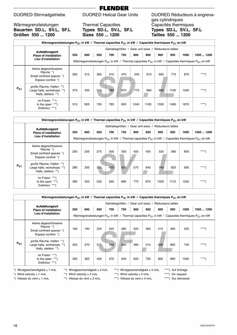
Wärmegrenzleistungen Thermal Capacities Capacités thermiquesBauarten SD.L, SV.L, SF.L Types SD.L, SV.L, SF.L Types SD.L, SV.L, SF.LGrößen 550 ... 1200 Sizes 550 ... 1200 Tailles 550 ... 1200
Wärmegrenzleistungen PG1 in kW / Thermal capacities PG1 in kW / Capacités thermiques PG1 en kW
A fstell ngsortGetriebegrößen / Gear unit sizes / Réducteurs tailles
AufstellungsortPlace of installation 550 600 650 700 750 800 850 900 950 1000 1050 ... 1200Place of installationLieu d’installation
Wärmegrenzleistungen PG1 in kW / Thermal capacities PG1 in kW / Capacités thermiques PG1 en kW
kleine abgeschlosseneRäume *)
Small confined spaces *)
Espace confiné *)
265 315 365 410 470 540 610 695 775 870 ****)
PG1große Räume, Hallen **)
Large halls, workshops **)Halls, ateliers **)
375 450 515 580 670 770 860 980 1100 1240 ****)
im Freien ***)In the open ***)Extérieur ***)
510 605 700 785 905 1040 1165 1330 1490 1670 ****)
Wärmegrenzleistungen PG1 in kW / Thermal capacities PG1 in kW / Capacités thermiques PG1 en kW
A fstell ngsortGetriebegrößen / Gear unit sizes / Réducteurs tailles
AufstellungsortPlace of installation 550 600 650 700 750 800 850 900 950 1000 1050 ... 1200Place of installationLieu d’installation
Wärmegrenzleistungen PG1 in kW / Thermal capacities PG1 in kW / Capacités thermiques PG1 en kW
kleine abgeschlosseneRäume *)
Small confined spaces *)
Espace confiné *)
200 235 275 305 355 405 455 520 580 655 ****)
PG1große Räume, Hallen **)
Large halls, workshops **)Halls, ateliers **)
285 335 385 435 500 575 645 740 825 930 ****)
im Freien ***)In the open ***)Extérieur ***)
380 455 525 590 680 775 870 1000 1110 1250 ****)
Wärmegrenzleistungen PG1 in kW / Thermal capacities PG1 in kW / Capacités thermiques PG1 en kW
A fstell ngsortGetriebegrößen / Gear unit sizes / Réducteurs tailles
AufstellungsortPlace of installation 550 600 650 700 750 800 850 900 950 1000 1050 ... 1200Place of installationLieu d’installation
Wärmegrenzleistungen PG1 in kW / Thermal capacities PG1 in kW / Capacités thermiques PG1 en kW
kleine abgeschlosseneRäume *)
Small confined spaces *)
Espace confiné *)
160 190 220 245 285 325 365 415 465 525 ****)
PG1große Räume, Hallen **)
Large halls, workshops **)Halls, ateliers **)
225 270 310 345 400 460 515 590 660 740 ****)
im Freien ***)In the open ***)Extérieur ***)
305 365 420 470 545 625 700 800 890 1000 ****)
*) Windgeschwindigkeit ≥ 1 m/s, **) Windgeschwindigkeit ≥ 2 m/s, ***) Windgeschwindigkeit ≥ 4 m/s, ****) Auf Anfrage
*) Wind velocity ≥ 1 m/s, **) Wind velocity ≥ 2 m/s, ***) Wind velocity ≥ 4 m/s, ****) On request
*) Vitesse du vent ≥ 1 m/s, **) Vitesse du vent ≥ 2 m/s, ***) Vitesse du vent ≥ 4 m/s, ****) Sur demande
SD . L
SV . L
SF . L
17K228 DE/EN/FR
DUORED-Stirnradgetriebe DUORED Helical Gear Units DUORED Réducteurs à engrena-ges cylindriques
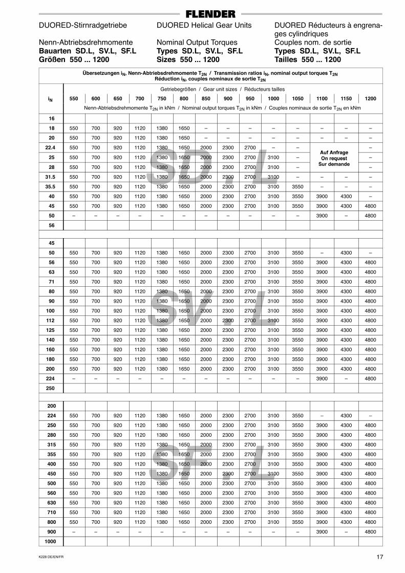
Nenn-Abtriebsdrehmomente Nominal Output Torques Couples nom. de sortieBauarten SD.L, SV.L, SF.L Types SD.L, SV.L, SF.L Types SD.L, SV.L, SF.LGrößen 550 ... 1200 Sizes 550 ... 1200 Tailles 550 ... 1200
Übersetzungen iN, Nenn-Abtriebsdrehmomente T2N / Transmission ratios iN, nominal output torques T2NRéduction iN, couples nominaux de sortie T2N
Getriebegrößen / Gear unit sizes / Réducteurs tailles
iN 550 600 650 700 750 800 850 900 950 1000 1050 1100 1150 1200N
Nenn-Abtriebsdrehmomente T2N in kNm / Nominal output torques T2N in kNm / Couples nominaux de sortie T2N en kNm
16
18 550 700 920 1120 1380 1650 – – – – – – – –
20 550 700 920 1120 1380 1650 – – – – – – – –
22.4 550 700 920 1120 1380 1650 2000 2300 2700 – –A f Anfrage
–
25 550 700 920 1120 1380 1650 2000 2300 2700 3100 –Auf AnfrageOn request
S d d–
28 550 700 920 1120 1380 1650 2000 2300 2700 3100 –
On requestSur demande
–
31.5 550 700 920 1120 1380 1650 2000 2300 2700 3100 – – – –
35.5 550 700 920 1120 1380 1650 2000 2300 2700 3100 3550 – – –
40 550 700 920 1120 1380 1650 2000 2300 2700 3100 3550 3900 4300 –
45 550 700 920 1120 1380 1650 2000 2300 2700 3100 3550 3900 4300 4800
50 – – – – – – – – – – – 3900 – 4800
56
45
50 550 700 920 1120 1380 1650 2000 2300 2700 3100 3550 – 4300 –
56 550 700 920 1120 1380 1650 2000 2300 2700 3100 3550 3900 4300 4800
63 550 700 920 1120 1380 1650 2000 2300 2700 3100 3550 3900 4300 4800
71 550 700 920 1120 1380 1650 2000 2300 2700 3100 3550 3900 4300 4800
80 550 700 920 1120 1380 1650 2000 2300 2700 3100 3550 3900 4300 4800
90 550 700 920 1120 1380 1650 2000 2300 2700 3100 3550 3900 4300 4800
100 550 700 920 1120 1380 1650 2000 2300 2700 3100 3550 3900 4300 4800
112 550 700 920 1120 1380 1650 2000 2300 2700 3100 3550 3900 4300 4800
125 550 700 920 1120 1380 1650 2000 2300 2700 3100 3550 3900 4300 4800
140 550 700 920 1120 1380 1650 2000 2300 2700 3100 3550 3900 4300 4800
160 550 700 920 1120 1380 1650 2000 2300 2700 3100 3550 3900 4300 4800
180 550 700 920 1120 1380 1650 2000 2300 2700 3100 3550 3900 4300 4800
200 550 700 920 1120 1380 1650 2000 2300 2700 3100 3550 3900 4300 4800
224 – – – – – – – – – – – 3900 – 4800
250
200
224 550 700 920 1120 1380 1650 2000 2300 2700 3100 3550 – 4300 –
250 550 700 920 1120 1380 1650 2000 2300 2700 3100 3550 3900 4300 4800
280 550 700 920 1120 1380 1650 2000 2300 2700 3100 3550 3900 4300 4800
315 550 700 920 1120 1380 1650 2000 2300 2700 3100 3550 3900 4300 4800
355 550 700 920 1120 1380 1650 2000 2300 2700 3100 3550 3900 4300 4800
400 550 700 920 1120 1380 1650 2000 2300 2700 3100 3550 3900 4300 4800
450 550 700 920 1120 1380 1650 2000 2300 2700 3100 3550 3900 4300 4800
500 550 700 920 1120 1380 1650 2000 2300 2700 3100 3550 3900 4300 4800
560 550 700 920 1120 1380 1650 2000 2300 2700 3100 3550 3900 4300 4800
630 550 700 920 1120 1380 1650 2000 2300 2700 3100 3550 3900 4300 4800
710 550 700 920 1120 1380 1650 2000 2300 2700 3100 3550 3900 4300 4800
800 550 700 920 1120 1380 1650 2000 2300 2700 3100 3550 3900 4300 4800
900 – – – – – – – – – – – 3900 – 4800
1000

K228 DE/EN/FR18
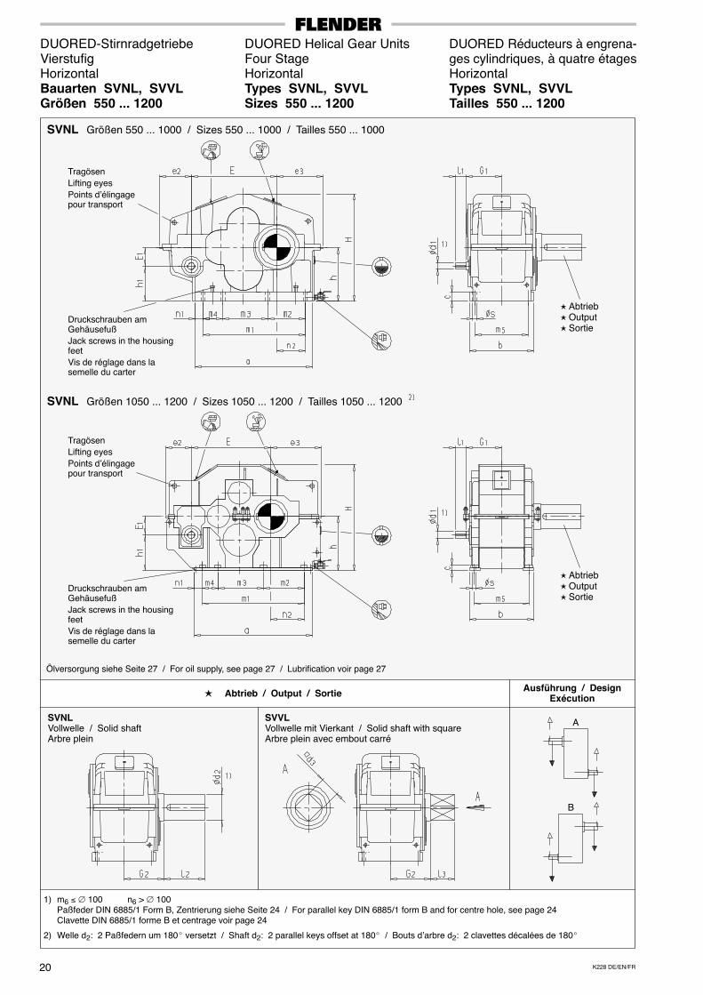
DUORED-Stirnradgetriebe DUORED Helical Gear Units DUORED Réducteurs à engrena-Dreistufig Three Stage ges cylindriques, à trois étagesHorizontal Horizontal HorizontalBauarten SDNL, SDVL Types SDNL, SDVL Types SDNL, SDVLGrößen 550 ... 1200 Sizes 550 ... 1200 Tailles 550 ... 1200
1) m6 ≤ ∅ 100 n6 > ∅ 100Paßfeder DIN 6885/1 Form B, Zentrierung siehe Seite 24 / For parallel key DIN 6885/1 form B and for centre hole, see page 24Clavette DIN 6885/1 forme B et centrage voir page 24
2) Welle d2: 2 Paßfedern um 180� versetzt / Shaft d2: 2 parallel keys offset at 180� / Bouts d’arbre d2: 2 clavettes décalées de 180�
SDNL
� Abtrieb / Output / Sortie
SDNLVollwelle / Solid shaftArbre plein
SDVLVollwelle mit Vierkant / Solid shaft with squareArbre plein avec embout carré
Ausführung / DesignExécution
� Abtrieb� Output� Sortie
Tragösen
Lifting eyes
Points d’élingagepour transport
Druckschrauben amGehäusefuß
Jack screws in the housingfeet
Vis de réglage dans lasemelle du carter
Ölversorgung siehe Seite 27 / For oil supply, see page 27 / Lubrification voir page 27
A
B
� Abtrieb� Output� Sortie
Tragösen
Lifting eyes
Points d’élingagepour transport
Druckschrauben amGehäusefuß
Jack screws in the housingfeet
Vis de réglage dans lasemelle du carter
SDNL
Größen 550 ... 1000 / Sizes 550 ... 1000 / Tailles 550 ... 1000
Größen 1050 ... 1200 / Sizes 1050 ... 1200 / Tailles 1050 ... 1200
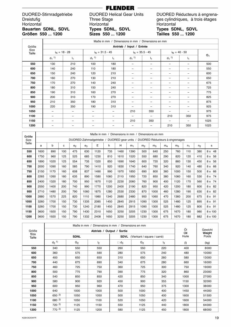
19K228 DE/EN/FR
DUORED-Stirnradgetriebe DUORED Helical Gear Units DUORED Réducteurs à engrena-Dreistufig Three Stage ges cylindriques, à trois étagesHorizontal Horizontal HorizontalBauarten SDNL, SDVL Types SDNL, SDVL Types SDNL, SDVLGrößen 550 ... 1200 Sizes 550 ... 1200 Tailles 550 ... 1200
Maße in mm / Dimensions in mm / Dimensions en mm
GrößeSi
Antrieb / Input / EntréeSizeTaille iN = 18 - 28 iN = 31.5 - 45 iN = 35.5 - 45 iN = 40 - 50
GTaille
d1 1) l1 d1 1) l1 d1 1) l1 d1 1) l1G1
550 130 210 100 180 – – – – 500
600 140 240 110 180 – – – – 550
650 150 240 120 210 – – – – 600
700 160 270 130 210 – – – – 650
750 170 270 140 240 – – – – 675
800 180 310 150 240 – – – – 725
850 190 310 160 270 – – – – 775
900 200 310 170 270 – – – – 825
950 210 350 180 310 – – – – 875
1000 220 350 190 310 – – – – 925
1050 – – – – 210 350 – – 975
1100 – – – – – – 210 350 975
1150 – – – – 210 350 – – 1025
1200 – – – – – – 210 350 1025
GrößeMaße in mm / Dimensions in mm / Dimensions en mm
GrößeSizeT ill
DUORED-Zahnradgetriebe / DUORED gear units / DUORED Réducteurs à engrenagesTaille
a b c e2 e3 E h H m1 m2 m3 m4 m5 n1 n2 s
550 1600 890 100 475 630 1120 735 1460 1390 500 640 250 760 110 380 8 x 48
600 1750 960 125 525 685 1230 810 1610 1520 550 680 290 820 120 410 8 x 56
650 1890 1020 125 554 735 1320 850 1690 1640 600 720 320 860 130 450 8 x 56
700 2000 1090 160 585 790 1410 920 1830 1740 640 760 340 920 140 480 8 x 66
750 2150 1170 160 608 837 1490 990 1970 1850 690 800 360 1000 150 500 8 x 66
800 2265 1260 180 635 890 1580 1060 2110 1950 720 850 380 1060 160 530 8 x 74
850 2400 1320 180 700 950 1670 1120 2230 2060 760 900 400 1120 170 560 8 x 74
900 2550 1400 200 740 990 1770 1200 2400 2190 820 950 420 1200 180 600 8 x 82
950 2710 1480 200 790 1060 1875 1280 2530 2330 870 1000 460 1280 190 630 8 x 82
1000 2880 1570 225 820 1110 1980 1340 2680 2480 950 1060 470 1360 200 675 8 x 91
1050 3260 1700 150 730 1335 2085 1450 2845 2915 1090 1300 525 1480 125 895 8 x 91
1100 3260 1700 150 730 1240 2180 1450 2845 2915 1090 1300 525 1480 125 800 8 x 91
1150 3600 1920 150 790 1430 2310 1650 3250 3205 1230 1300 675 1670 180 980 8 x 100
1200 3600 1920 150 790 1332 2408 1650 3250 3205 1230 1300 675 1670 180 882 8 x 100
Maße in mm / Dimensions in mm / Dimensions en mm
ÖGrößeSize
Abtrieb / Output / Sortie ÖlOil
GewichtWeightSize
Taille SDNL SDVL (Vierkant / square / carré)Oil
HuileWeightPoidsTaille
d2 1) G2 l2 � d3 G2 l3 (l) (kg)
550 340 550 550 260 550 220 400 8 000
600 360 575 590 280 575 240 480 10 000
650 400 650 650 310 650 260 580 13 000
700 440 675 690 340 675 280 660 16 000
750 460 725 750 360 725 300 750 19 000
800 500 775 790 390 775 320 860 23 000
850 540 850 850 420 850 340 1000 27 000
900 580 900 920 450 900 355 1150 32 000
950 600 950 960 470 950 375 1300 38 000
1000 640 1000 1000 500 1000 400 1450 44 000
1050 650 2) 1050 1050 500 1050 400 1600 51 500
1100 680 2) 1050 1100 520 1050 420 1600 54 000
1150 720 2) 1125 1150 550 1125 440 1800 64 000
1200 770 2) 1125 1200 580 1125 450 1800 68 000
K228 DE/EN/FR20
DUORED-Stirnradgetriebe DUORED Helical Gear Units DUORED Réducteurs à engrena-Vierstufig Four Stage ges cylindriques, à quatre étagesHorizontal Horizontal HorizontalBauarten SVNL, SVVL Types SVNL, SVVL Types SVNL, SVVLGrößen 550 ... 1200 Sizes 550 ... 1200 Tailles 550 ... 1200
1) m6 ≤ ∅ 100 n6 > ∅ 100Paßfeder DIN 6885/1 Form B, Zentrierung siehe Seite 24 / For parallel key DIN 6885/1 form B and for centre hole, see page 24Clavette DIN 6885/1 forme B et centrage voir page 24
2) Welle d2: 2 Paßfedern um 180� versetzt / Shaft d2: 2 parallel keys offset at 180� / Bouts d’arbre d2: 2 clavettes décalées de 180�
SVNL
� Abtrieb / Output / Sortie
SVNLVollwelle / Solid shaftArbre plein
SVVLVollwelle mit Vierkant / Solid shaft with squareArbre plein avec embout carré
Ausführung / DesignExécution
� Abtrieb� Output� Sortie
Tragösen
Lifting eyes
Points d’élingagepour transport
Druckschrauben amGehäusefuß
Jack screws in the housingfeet
Vis de réglage dans lasemelle du carter
Ölversorgung siehe Seite 27 / For oil supply, see page 27 / Lubrification voir page 27
A
B
� Abtrieb� Output� Sortie
Tragösen
Lifting eyes
Points d’élingagepour transport
Druckschrauben amGehäusefuß
Jack screws in the housingfeet
Vis de réglage dans lasemelle du carter
SVNL
Größen 550 ... 1000 / Sizes 550 ... 1000 / Tailles 550 ... 1000
Größen 1050 ... 1200 / Sizes 1050 ... 1200 / Tailles 1050 ... 1200
21K228 DE/EN/FR
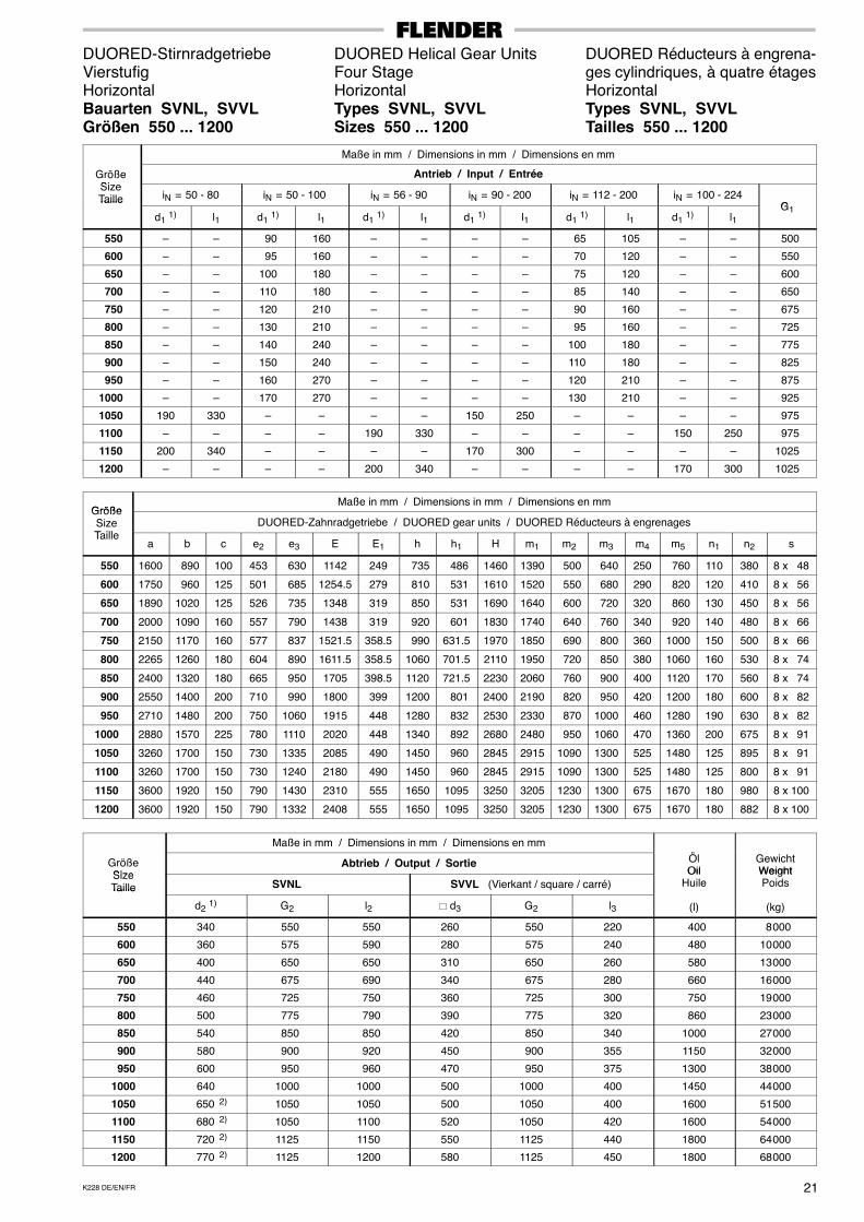
DUORED-Stirnradgetriebe DUORED Helical Gear Units DUORED Réducteurs à engrena-Vierstufig Four Stage ges cylindriques, à quatre étagesHorizontal Horizontal HorizontalBauarten SVNL, SVVL Types SVNL, SVVL Types SVNL, SVVLGrößen 550 ... 1200 Sizes 550 ... 1200 Tailles 550 ... 1200
Maße in mm / Dimensions in mm / Dimensions en mm
GrößeSi
Antrieb / Input / EntréeSizeTaille iN = 50 - 80 iN = 50 - 100 iN = 56 - 90 iN = 90 - 200 iN = 112 - 200 iN = 100 - 224
GTaille
d1 1) l1 d1 1) l1 d1 1) l1 d1 1) l1 d1 1) l1 d1 1) l1G1
550 – – 90 160 – – – – 65 105 – – 500
600 – – 95 160 – – – – 70 120 – – 550
650 – – 100 180 – – – – 75 120 – – 600
700 – – 110 180 – – – – 85 140 – – 650
750 – – 120 210 – – – – 90 160 – – 675
800 – – 130 210 – – – – 95 160 – – 725
850 – – 140 240 – – – – 100 180 – – 775
900 – – 150 240 – – – – 110 180 – – 825
950 – – 160 270 – – – – 120 210 – – 875
1000 – – 170 270 – – – – 130 210 – – 925
1050 190 330 – – – – 150 250 – – – – 975
1100 – – – – 190 330 – – – – 150 250 975
1150 200 340 – – – – 170 300 – – – – 1025
1200 – – – – 200 340 – – – – 170 300 1025
GrößeMaße in mm / Dimensions in mm / Dimensions en mm
GrößeSizeT ill
DUORED-Zahnradgetriebe / DUORED gear units / DUORED Réducteurs à engrenagesTaille
a b c e2 e3 E E1 h h1 H m1 m2 m3 m4 m5 n1 n2 s
550 1600 890 100 453 630 1142 249 735 486 1460 1390 500 640 250 760 110 380 8 x 48
600 1750 960 125 501 685 1254.5 279 810 531 1610 1520 550 680 290 820 120 410 8 x 56
650 1890 1020 125 526 735 1348 319 850 531 1690 1640 600 720 320 860 130 450 8 x 56
700 2000 1090 160 557 790 1438 319 920 601 1830 1740 640 760 340 920 140 480 8 x 66
750 2150 1170 160 577 837 1521.5 358.5 990 631.5 1970 1850 690 800 360 1000 150 500 8 x 66
800 2265 1260 180 604 890 1611.5 358.5 1060 701.5 2110 1950 720 850 380 1060 160 530 8 x 74
850 2400 1320 180 665 950 1705 398.5 1120 721.5 2230 2060 760 900 400 1120 170 560 8 x 74
900 2550 1400 200 710 990 1800 399 1200 801 2400 2190 820 950 420 1200 180 600 8 x 82
950 2710 1480 200 750 1060 1915 448 1280 832 2530 2330 870 1000 460 1280 190 630 8 x 82
1000 2880 1570 225 780 1110 2020 448 1340 892 2680 2480 950 1060 470 1360 200 675 8 x 91
1050 3260 1700 150 730 1335 2085 490 1450 960 2845 2915 1090 1300 525 1480 125 895 8 x 91
1100 3260 1700 150 730 1240 2180 490 1450 960 2845 2915 1090 1300 525 1480 125 800 8 x 91
1150 3600 1920 150 790 1430 2310 555 1650 1095 3250 3205 1230 1300 675 1670 180 980 8 x 100
1200 3600 1920 150 790 1332 2408 555 1650 1095 3250 3205 1230 1300 675 1670 180 882 8 x 100
Maße in mm / Dimensions in mm / Dimensions en mm
ÖGrößeSize
Abtrieb / Output / Sortie ÖlOil
GewichtWeightSize
Taille SVNL SVVL (Vierkant / square / carré)Oil
HuileWeightPoidsTaille
d2 1) G2 l2 � d3 G2 l3 (l) (kg)
550 340 550 550 260 550 220 400 8 000
600 360 575 590 280 575 240 480 10 000
650 400 650 650 310 650 260 580 13 000
700 440 675 690 340 675 280 660 16 000
750 460 725 750 360 725 300 750 19 000
800 500 775 790 390 775 320 860 23 000
850 540 850 850 420 850 340 1000 27 000
900 580 900 920 450 900 355 1150 32 000
950 600 950 960 470 950 375 1300 38 000
1000 640 1000 1000 500 1000 400 1450 44 000
1050 650 2) 1050 1050 500 1050 400 1600 51 500
1100 680 2) 1050 1100 520 1050 420 1600 54 000
1150 720 2) 1125 1150 550 1125 440 1800 64 000
1200 770 2) 1125 1200 580 1125 450 1800 68 000

K228 DE/EN/FR22
DUORED-Stirnradgetriebe DUORED Helical Gear Units DUORED Réducteurs à engrena-Fünfstufig Five Stage ges cylindriques, à cinq étagesHorizontal Horizontal HorizontalBauarten SFNL, SFVL Types SFNL, SFVL Types SFNL, SFVLGrößen 550 ... 1200 Sizes 550 ... 1200 Tailles 550 ... 1200
1) m6 ≤ ∅ 100 n6 > ∅ 100Paßfeder DIN 6885/1 Form B, Zentrierung siehe Seite 24 / For parallel key DIN 6885/1 form B and for centre hole, see page 24Clavette DIN 6885/1 forme B et centrage voir page 24
2) Welle d2: 2 Paßfedern um 180� versetzt / Shaft d2: 2 parallel keys offset at 180� / Bouts d’arbre d2: 2 clavettes décalées de 180�
SFNL
� Abtrieb / Output / Sortie
SFNLVollwelle / Solid shaftArbre plein
SFVLVollwelle mit Vierkant / Solid shaft with squareArbre plein avec embout carré
Ausführung / DesignExécution
� Abtrieb� Output� Sortie
Tragösen
Lifting eyes
Points d’élingagepour transport
Druckschrauben amGehäusefuß
Jack screws in the housingfeet
Vis de réglage dans lasemelle du carter
Ölversorgung siehe Seite 27 / For oil supply, see page 27 / Lubrification voir page 27
A
B
� Abtrieb� Output� Sortie
Tragösen
Lifting eyes
Points d’élingagepour transport
Druckschrauben amGehäusefuß
Jack screws in the housingfeet
Vis de réglage dans lasemelle du carter
SFNL
Größen 550 ... 1000 / Sizes 550 ... 1000 / Tailles 550 ... 1000
Größen 1050 ... 1200 / Sizes 1050 ... 1200 / Tailles 1050 ... 1200
23K228 DE/EN/FR
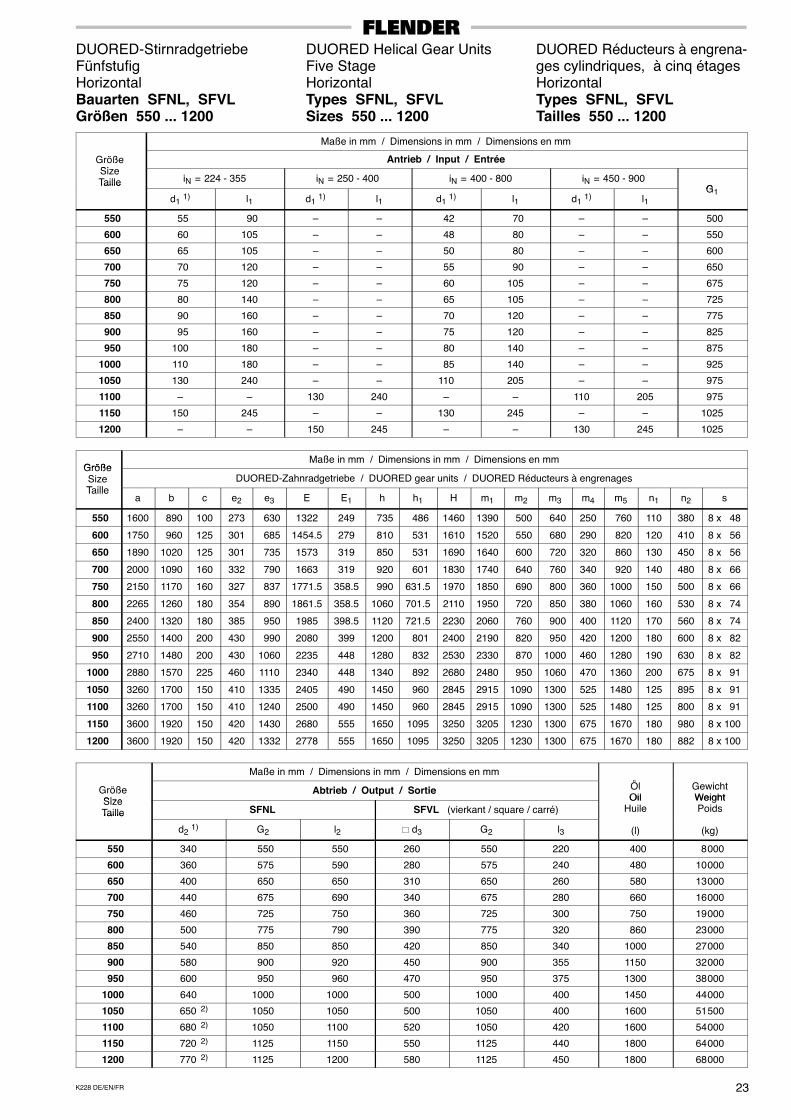
DUORED-Stirnradgetriebe DUORED Helical Gear Units DUORED Réducteurs à engrena-Fünfstufig Five Stage ges cylindriques, à cinq étagesHorizontal Horizontal HorizontalBauarten SFNL, SFVL Types SFNL, SFVL Types SFNL, SFVLGrößen 550 ... 1200 Sizes 550 ... 1200 Tailles 550 ... 1200
Maße in mm / Dimensions in mm / Dimensions en mm
GrößeSi
Antrieb / Input / EntréeSizeTaille iN = 224 - 355 iN = 250 - 400 iN = 400 - 800 iN = 450 - 900
GTaille
d1 1) l1 d1 1) l1 d1 1) l1 d1 1) l1G1
550 55 90 – – 42 70 – – 500
600 60 105 – – 48 80 – – 550
650 65 105 – – 50 80 – – 600
700 70 120 – – 55 90 – – 650
750 75 120 – – 60 105 – – 675
800 80 140 – – 65 105 – – 725
850 90 160 – – 70 120 – – 775
900 95 160 – – 75 120 – – 825
950 100 180 – – 80 140 – – 875
1000 110 180 – – 85 140 – – 925
1050 130 240 – – 110 205 – – 975
1100 – – 130 240 – – 110 205 975
1150 150 245 – – 130 245 – – 1025
1200 – – 150 245 – – 130 245 1025
GrößeMaße in mm / Dimensions in mm / Dimensions en mm
GrößeSizeT ill
DUORED-Zahnradgetriebe / DUORED gear units / DUORED Réducteurs à engrenagesTaille
a b c e2 e3 E E1 h h1 H m1 m2 m3 m4 m5 n1 n2 s
550 1600 890 100 273 630 1322 249 735 486 1460 1390 500 640 250 760 110 380 8 x 48
600 1750 960 125 301 685 1454.5 279 810 531 1610 1520 550 680 290 820 120 410 8 x 56
650 1890 1020 125 301 735 1573 319 850 531 1690 1640 600 720 320 860 130 450 8 x 56
700 2000 1090 160 332 790 1663 319 920 601 1830 1740 640 760 340 920 140 480 8 x 66
750 2150 1170 160 327 837 1771.5 358.5 990 631.5 1970 1850 690 800 360 1000 150 500 8 x 66
800 2265 1260 180 354 890 1861.5 358.5 1060 701.5 2110 1950 720 850 380 1060 160 530 8 x 74
850 2400 1320 180 385 950 1985 398.5 1120 721.5 2230 2060 760 900 400 1120 170 560 8 x 74
900 2550 1400 200 430 990 2080 399 1200 801 2400 2190 820 950 420 1200 180 600 8 x 82
950 2710 1480 200 430 1060 2235 448 1280 832 2530 2330 870 1000 460 1280 190 630 8 x 82
1000 2880 1570 225 460 1110 2340 448 1340 892 2680 2480 950 1060 470 1360 200 675 8 x 91
1050 3260 1700 150 410 1335 2405 490 1450 960 2845 2915 1090 1300 525 1480 125 895 8 x 91
1100 3260 1700 150 410 1240 2500 490 1450 960 2845 2915 1090 1300 525 1480 125 800 8 x 91
1150 3600 1920 150 420 1430 2680 555 1650 1095 3250 3205 1230 1300 675 1670 180 980 8 x 100
1200 3600 1920 150 420 1332 2778 555 1650 1095 3250 3205 1230 1300 675 1670 180 882 8 x 100
Maße in mm / Dimensions in mm / Dimensions en mm
ÖGrößeSize
Abtrieb / Output / Sortie ÖlOil
GewichtWeightSize
Taille SFNL SFVL (vierkant / square / carré)Oil
HuileWeightPoidsTaille
d2 1) G2 l2 � d3 G2 l3 (l) (kg)
550 340 550 550 260 550 220 400 8 000
600 360 575 590 280 575 240 480 10 000
650 400 650 650 310 650 260 580 13 000
700 440 675 690 340 675 280 660 16 000
750 460 725 750 360 725 300 750 19 000
800 500 775 790 390 775 320 860 23 000
850 540 850 850 420 850 340 1000 27 000
900 580 900 920 450 900 355 1150 32 000
950 600 950 960 470 950 375 1300 38 000
1000 640 1000 1000 500 1000 400 1450 44 000
1050 650 2) 1050 1050 500 1050 400 1600 51 500
1100 680 2) 1050 1100 520 1050 420 1600 54 000
1150 720 2) 1125 1150 550 1125 440 1800 64 000
1200 770 2) 1125 1200 580 1125 450 1800 68 000
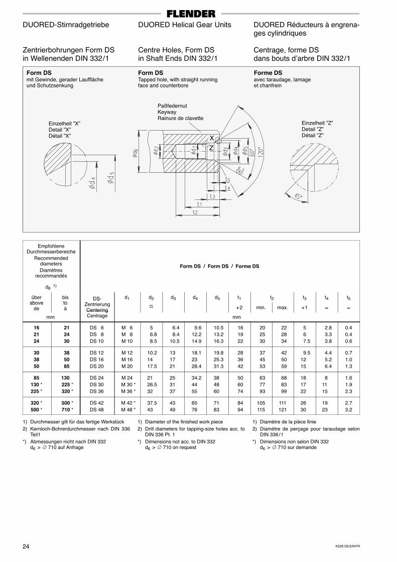
K228 DE/EN/FR24
DUORED-Stirnradgetriebe DUORED Helical Gear Units DUORED Réducteurs à engrena-ges cylindriques
Zentrierbohrungen Form DS Centre Holes, Form DS Centrage, forme DSin Wellenenden DIN 332 / 1 in Shaft Ends DIN 332 / 1 dans bouts d’arbre DIN 332 / 1
PaßfedernutKeywayRainure de clavette
Einzelheit ”X”Detail ”X”Détail ”X”
Form DSmit Gewinde, gerader Laufflächeund Schutzsenkung
Z
X
Forme DSavec taraudage, lamageet chanfrein
Form DSTapped hole, with straight runningface and counterbore
Einzelheit ”Z”Detail ”Z”Détail ”Z”
EmpfohleneDurchmesserbereiche
Recommendeddiameters
Diamètresrecommandés
d6 1)
Form DS / Form DS / Forme DS
überabove
bisto
DS- d1 d2 d3 d4 d5 t1 t2 t3 t4 t5above
detoà
DSZentrierungCentering
2) + 2 min. max. + 1 ≈ ≈
mm
CenteringCentrage mm
162124
21 24 30
DS 6
DS 8
DS 10
M 6
M 8
M 10
5
6.8
8.5
6.4
8.4
10.5
9.6
12.2
14.9
10.5
13.2
16.3
16
19
22
20
25
30
22
28
34
5
6
7.5
2.8
3.3
3.8
0.4
0.4
0.6
303850
38 50 85
DS 12
DS 16
DS 20
M 12
M 16
M 20
10.2
14
17.5
13
17
21
18.1
23
28.4
19.8
25.3
31.3
28
36
42
37
45
53
42
50
59
9.5
12
15
4.4
5.2
6.4
0.7
1.0
1.3
85130 *225 *
130 225 * 320 *
DS 24
DS 30
DS 36
M 24
M 30 *
M 36 *
21
26.5
32
25
31
37
34.2
44
55
38
48
60
50
60
74
63
77
93
68
83
99
18
17
22
8
11
15
1.6
1.9
2.3
320 *500 *
500 * 710 *
DS 42
DS 48
M 42 *
M 48 *
37.5
43
43
49
65
76
71
83
84
94
105
115
111
121
26
30
19
23
2.7
3.2
1) Durchmesser gilt für das fertige Werkstück
2) Kernloch-Bohrerdurchmesser nach DIN 336Teil1
*) Abmessungen nicht nach DIN 332d6 > ∅ 710 auf Anfrage
1) Diameter of the finished work piece
2) Drill diameters for tapping-size holes acc. toDIN 336 Pt. 1
*) Dimensions not acc. to DIN 332d6 > ∅ 710 on request
1) Diamètre de la pièce finie
2) Diamètre de perçage pour taraudage selonDIN 336 / 1
*) Dimensions non selon DIN 332d6 > ∅ 710 sur demande
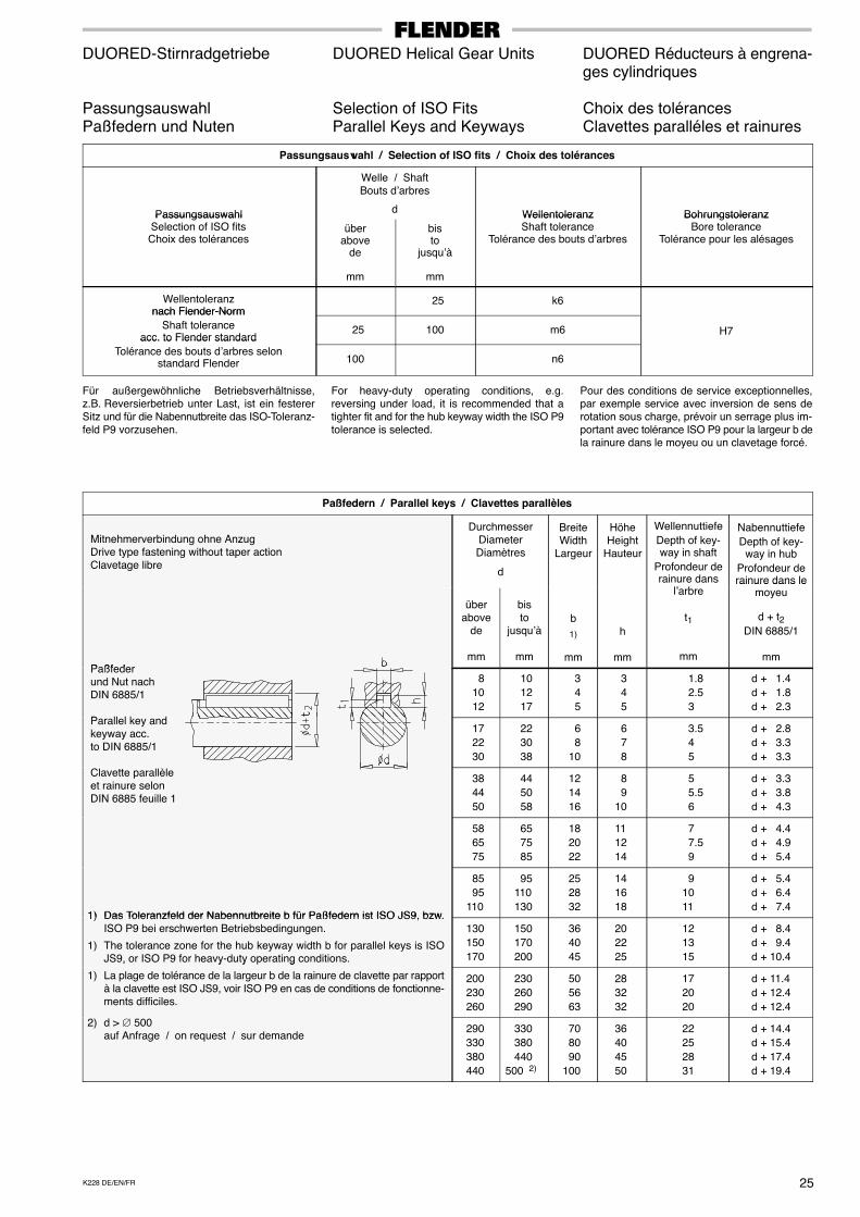
25K228 DE/EN/FR
DUORED-Stirnradgetriebe DUORED Helical Gear Units DUORED Réducteurs à engrena-ges cylindriques
Passungsauswahl Selection of ISO Fits Choix des tolérancesPaßfedern und Nuten Parallel Keys and Keyways Clavettes paralléles et rainures
Passungsauswahl / Selection of ISO fits / Choix des tolérances
Passungsauswahl
Welle / ShaftBouts d’arbres
d Wellentoleranz BohrungstoleranzPassungsauswahlSelection of ISO fitsChoix des tolérances
überabove
de
mm
bisto
jusqu’à
mm
WellentoleranzShaft tolerance
Tolérance des bouts d’arbres
BohrungstoleranzBore tolerance
Tolérance pour les alésages
Wellentoleranznach Flender-Norm
25 k6nach Flender-Norm
Shaft toleranceacc. to Flender standard
25 100 m6 H7acc. to Flender standard
Tolérance des bouts d’arbres selonstandard Flender 100 n6
Für außergewöhnliche Betriebsverhältnisse,z.B. Reversierbetrieb unter Last, ist ein festererSitz und für die Nabennutbreite das ISO-Toleranz-feld P9 vorzusehen.
For heavy-duty operating conditions, e.g.reversing under load, it is recommended that atighter fit and for the hub keyway width the ISO P9tolerance is selected.
Pour des conditions de service exceptionnelles,par exemple service avec inversion de sens derotation sous charge, prévoir un serrage plus im-portant avec tolérance ISO P9 pour la largeur b dela rainure dans le moyeu ou un clavetage forcé.
Paßfedern / Parallel keys / Clavettes parallèles
Mitnehmerverbindung ohne Anzug Drive type fastening without taper action Clavetage libre
DurchmesserDiameterDiamètres
d
BreiteWidth
Largeur
HöheHeight
Hauteur
Wellennuttiefe
Depth of key-way in shaft
Profondeur derainure dans
l’ b
Nabennuttiefe
Depth of key-way in hub
Profondeur derainure dans le
Paßfeder
überabove
de
mm
bisto
jusqu’à
mm
b
1)
mm
h
mm
l’arbre
t1
mm
rainure dans lemoyeu
d + t2DIN 6885/1
mm Paßfeder und Nut nach DIN 6885/1
P ll l k d
8
10
12
10
12
17
3
4
5
3
4
5
1.8
2.5
3
d + 1.4
d + 1.8
d + 2.3
Parallel key and keyway acc. to DIN 6885/1
17
22
30
22
30
38
6
8
10
6
7
8
3.5
4
5
d + 2.8
d + 3.3
d + 3.3
Clavette parallèle et rainure selon DIN 6885 feuille 1
38
44
50
44
50
58
12
14
16
8
9
10
5
5.5
6
d + 3.3
d + 3.8
d + 4.3
58
65
75
65
75
85
18
20
22
11
12
14
7
7.5
9
d + 4.4
d + 4.9
d + 5.4
1) Das Toleranzfeld der Nabennutbreite b für Paßfedern ist ISO JS9 bzw
85
95
110
95
110
130
25
28
32
14
16
18
9
10
11
d + 5.4
d + 6.4
d + 7.41) Das Toleranzfeld der Nabennutbreite b für Paßfedern ist ISO JS9, bzw.
ISO P9 bei erschwerten Betriebsbedingungen.
1) The tolerance zone for the hub keyway width b for parallel keys is ISOJS9, or ISO P9 for heavy-duty operating conditions.
130
150
170
150
170
200
36
40
45
20
22
25
12
13
15
d + 8.4
d + 9.4
d + 10.4, y y g
1) La plage de tolérance de la largeur b de la rainure de clavette par rapportà la clavette est ISO JS9, voir ISO P9 en cas de conditions de fonctionne-ments difficiles.
200
230
260
230
260
290
50
56
63
28
32
32
17
20
20
d + 11.4
d + 12.4
d + 12.4
2) d > ∅ 500auf Anfrage / on request / sur demande
290
330
380
440
330
380
440
500 2)
70
80
90
100
36
40
45
50
22
25
28
31
d + 14.4
d + 15.4
d + 17.4
d + 19.4
SD . L
SV . L
SF . LK228 DE/EN/FR26
DUORED-Stirnradgetriebe DUORED Helical Gear Units DUORED Réducteurs à engrena-ges cylindriques
Ist-Übersetzungen Actual Ratios Rapports réelsBauarten SD.L, SV.L, SF.L Types SD.L, SV.L, SF.L Types SD.L, SV.L, SF.LGrößen 550 ... 1200 Sizes 550 ... 1200 Tailles 550 ... 1200
Ist-Übersetzungen i / Actual ratios i / Rapports réels i
Getriebegrößen / Gear unit sizes / Réducteurs tailles
iN 550 600 650 700 750 800 850 900 950 1000 1050 1100 1150 1200N
Ist-Übersetzungen i / Actual ratios i / Rapports réels i
18 18.947 19.358 18.874 17.964 18.643 19.252 18.805 18.566 18.805 18.698 – – – –
20 21.510 21.681 20.142 20.290 20.880 21.474 21.672 21.098 21.238 20.942 – – – –
22.4 22.967 24.391 23.041 21.604 23.490 24.051 22.614 24.112 24.115 23.560 – – – –
25 26.316 27.594 26.550 24.608 26.575 27.076 26.254 26.143 25.759 26.653 – – – –
28 30.409 31.438 28.077 28.244 30.276 30.677 30.113 29.135 29.565 30.366 – – – –
31.5 32.687 33.663 31.915 31.706 32.419 32.747 31.786 33.312 33.288 32.515 – – – –
35.5 38.227 38.227 36.604 36.090 36.291 37.091 36.683 37.976 35.936 36.125 35.996 – – –
40 43.659 43.099 42.074 41.620 41.714 40.000 42.188 43.350 41.330 41.476 39.499 39.447 39.912 –
45 46.753 46.852 45.245 44.569 47.368 45.158 48.559 46.899 46.659 47.516 45.736 43.287 46.283 43.333
50 – – – – – – – – – – – 50.121 – 50.250
50 51.170 53.655 53.101 49.216 53.149 54.151 52.508 52.286 50.086 51.826 50.785 – 48.966 –
56 59.942 60.058 58.690 54.396 59.055 60.168 57.141 56.899 56.063 58.010 57.134 55.655 57.173 53.163
63 69.266 68.423 62.066 62.435 67.280 68.170 65.539 63.411 64.347 66.090 63.012 62.612 63.739 62.074
71 76.918 77.670 68.633 69.042 75.690 76.692 76.954 74.456 72.270 74.227 72.323 69.054 73.057 69.202
80 84.470 87.327 77.992 78.456 85.782 86.917 85.821 83.035 82.471 84.704 80.441 79.258 81.892 79.319
90 97.630 97.622 87.187 87.706 94.015 95.259 93.507 90.472 92.919 95.435 89.970 88.154 92.409 88.911
100 104.942 104.532 99.103 98.456 100.669 101.689 98.702 103.443 104.619 102.190 103.355 98.597 105.485 100.330
112 114.404 119.503 114.220 113.475 116.026 117.201 112.085 117.469 119.136 116.369 111.117 113.266 113.333 114.526
125 132.468 134.651 125.885 125.064 128.055 129.352 128.815 135.002 134.904 131.771 125.128 121.772 120.750 123.048
140 151.293 151.813 144.695 144.227 147.190 139.497 148.149 154.105 155.153 151.293 142.088 137.127 138.056 131.100
160 176.936 172.398 165.959 164.167 164.771 158.000 170.974 175.680 167.494 168.089 155.917 155.713 157.432 149.889
180 191.616 191.792 188.226 186.194 190.032 182.222 185.160 190.257 183.918 184.570 178.785 170.868 175.614 170.926
200 205.193 208.491 202.412 199.386 215.789 205.719 213.121 205.833 207.633 211.447 207.014 195.929 203.645 190.667
224 – – – – – – – – – – – 226.865 – 221.100
224 239.333 248.882 217.558 218.852 238.283 241.437 238.391 230.652 229.086 235.289 223.125 – 232.870 –
250 276.618 278.223 243.207 244.653 261.153 264.609 259.742 251.311 258.107 265.097 259.357 244.520 248.109 252.830
280 303.167 303.143 274.017 275.647 301.837 305.832 290.365 280.939 288.537 296.350 291.004 284.227 278.246 269.376
315 325.874 324.599 311.466 309.435 323.202 326.476 306.496 321.218 324.871 317.326 320.129 318.908 318.123 302.095
355 355.256 371.089 358.978 356.636 372.504 376.277 348.055 364.774 369.949 361.357 344.172 350.827 341.793 345.391
400 409.447 421.406 408.788 406.122 406.090 410.204 397.903 417.016 426.381 416.480 380.955 377.175 388.023 371.089
450 467.632 475.114 469.872 468.350 466.770 442.377 457.627 476.025 490.380 478.180 347.632 417.485 442.928 421.282
500 546.892 539.537 538.921 533.102 522.526 501.053 528.133 542.668 529.388 531.266 494.221 479.597 495.745 480.894
560 611.232 620.064 610.249 603.660 605.030 580.166 595.079 611.457 583.451 585.521 542.321 541.612 565.323 538.237
630 707.742 698.664 672.570 665.308 667.758 640.316 683.897 702.720 660.673 663.017 621.862 594.325 630.614 613.779
710 757.888 759.493 723.260 712.448 758.269 722.883 787.172 760.252 745.865 759.564 698.114 681.492 711.237 684.667
800 852.624 822.510 783.271 771.561 821.184 782.862 875.729 845.781 845.940 861.477 808.342 765.056 824.761 772.200
900 – – – – – – – – – – – 885.855 – 895.455
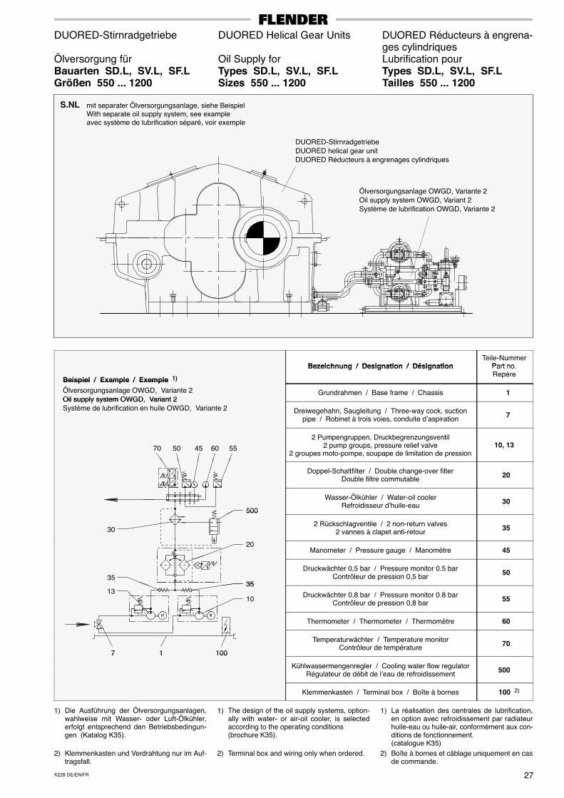
27K228 DE/EN/FR
DUORED-Stirnradgetriebe DUORED Helical Gear Units DUORED Réducteurs à engrena-ges cylindriques
Ölversorgung für Oil Supply for Lubrification pourBauarten SD.L, SV.L, SF.L Types SD.L, SV.L, SF.L Types SD.L, SV.L, SF.LGrößen 550 ... 1200 Sizes 550 ... 1200 Tailles 550 ... 1200
S.NL mit separater Ölversorgungsanlage, siehe BeispielWith separate oil supply system, see exampleavec système de lubrification séparé, voir exemple
DUORED-StirnradgetriebeDUORED helical gear unitDUORED Réducteurs à engrenages cylindriques
Ölversorgungsanlage OWGD, Variante 2Oil supply system OWGD, Variant 2Système de lubrification OWGD, Variante 2
Bezeichn ng / Designation / DésignationTeile-Nummer
Part no
Beispiel / Example / Exemple 1)
Bezeichnung / Designation / Désignation Part no.Repère
Beispiel / Example / Exemple 1)
Ölversorgungsanlage OWGD, Variante 2Oil supply system OWGD, Variant 2
Grundrahmen / Base frame / Chassis 1Oil supply system OWGD, Variant 2Système de lubrification en huile OWGD, Variante 2 Dreiwegehahn, Saugleitung / Three-way cock, suction
pipe / Robinet à trois voies, conduite d’aspiration 7
70 4550 60 55
2 Pumpengruppen, Druckbegrenzungsventil2 pump groups, pressure relief valve
2 groupes moto-pompe, soupape de limitation de pression10, 13
Doppel-Schaltfilter / Double change-over filterDouble filtre commutable
20
500
Wasser-Ölkühler / Water-oil coolerRefroidisseur d’huile-eau
30500
302 Rückschlagventile / 2 non-return valves
2 vannes à clapet anti-retour 35
20Manometer / Pressure gauge / Manomètre 45
3535
Druckwächter 0,5 bar / Pressure monitor 0.5 barContrôleur de pression 0,5 bar
50
10
3513 Druckwächter 0,8 bar / Pressure monitor 0.8 bar
Contrôleur de pression 0,8 bar 55
Thermometer / Thermometer / Thermomètre 60
7 1001
Temperaturwächter / Temperature monitorContrôleur de température
707 1001
Kühlwassermengenregler / Cooling water flow regulatorRégulateur de débit de l’eau de refroidissement
500
Klemmenkasten / Terminal box / Boîte à bornes 100 2)
1) Die Ausführung der Ölversorgungsanlagen,wahlweise mit Wasser- oder Luft-Ölkühler,erfolgt entsprechend den Betriebsbedingun-gen (Katalog K35).
2) Klemmenkasten und Verdrahtung nur im Auf-tragsfall.
1) The design of the oil supply systems, option-ally with water- or air-oil cooler, is selectedaccording to the operating conditions(brochure K35).
2) Terminal box and wiring only when ordered.
1) La réalisation des centrales de lubrification,en option avec refroidissement par radiateurhuile-eau ou huile-air, conformément aux con-ditions de fonctionnement.(catalogue K35)
2) Boîte à bornes et câblage uniquement en casde commande.
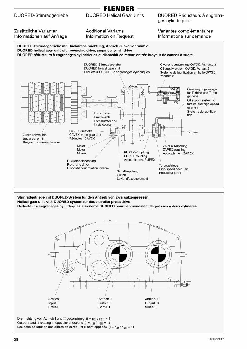
K228 DE/EN/FR28
DUORED-Stirnradgetriebe DUORED Helical Gear Units DUORED Réducteurs à engrena-ges cylindriques
Zusätzliche Varianten Additional Variants Variantes complémentairesInformationen auf Anfrage Information on Request Informations sur demande
DUORED-Stirnradgetriebe mit Rückdreheinrichtung, Antrieb ZuckerrohrmühleDUORED helical gear unit with reversing drive, sugar cane mill driveDUORED réducteurs à engrenages cylindriques et dispositif de retour, entrée broyeur de cannes à sucre
Endschalter
Limit switch
Commutateur defin de course
MotorMotorMoteur
TurbogetriebeHigh-speed gear unitRéducteur turbo
CAVEX-GetriebeCAVEX worm gear unitRéducteur CAVEX
RückdreheinrichtungReversing driveDispositif pour rotation inverse
SchaltkupplungClutchLevier d’accouplement
DUORED-StirnradgetriebeDUORED helical gear unitRéducteur DUORED à engrenages cylindriques
RUPEX-KupplungRUPEX couplingAccouplement RUPEX
ZAPEX-KupplungZAPEX couplingAccouplement ZAPEX
Turbine
Ölversorgungsanlage OWGD, Variante 2
Oil supply system OWGD, Variant 2
Système de lubrification en huile OWGD,Variante 2
Ölversorgungsanlagefür Turbine und Turbo-getriebe
Oil supply system forturbine and high-speedgear unit
Système de lubrifica-tion
ZuckerrohrmühleSugar cane millBroyeur de cannes à sucre
Stirnradgetriebe mit DUORED-System für den Antrieb von ZweiwalzenpressenHelical gear unit with DUORED system for double roller press driveRéducteur à engrenages cylindriques à système DUORED pour l’entraînement de presses à deux cylindres
Abtrieb ΙΙOutput ΙΙSortie ΙΙ
Drehrichtung von Abtrieb Ι und ΙΙ gegensinnig (i = n2Ι / n2ΙΙ = 1)Output Ι and ΙΙ rotating in opposite directions (i = n2Ι / n2ΙΙ = 1)Les sens de rotation des arbres de sortie Ι et ΙΙ sont opposés (i = n2Ι / n2ΙΙ = 1)
Abtrieb ΙOutput ΙSortie Ι
AntriebInputEntrée
29K228 DE/EN/FR
DUORED-Stirnradgetriebe DUORED Helical Gear Units DUORED Réducteurs à engrena-ges cylindriques
Bemerkungen Notes Notes
.............................................................................
.............................................................................
.............................................................................
.............................................................................
.............................................................................
.............................................................................
.............................................................................
.............................................................................
.............................................................................
.............................................................................
.............................................................................
.............................................................................
.............................................................................
.............................................................................
.............................................................................
.............................................................................
.............................................................................
.............................................................................
.............................................................................
.............................................................................
.............................................................................
.............................................................................
.............................................................................
.............................................................................
.............................................................................
.............................................................................
.............................................................................
.............................................................................
.............................................................................
.............................................................................
.............................................................................
.............................................................................
.............................................................................
.............................................................................
.............................................................................
.............................................................................
.............................................................................
.............................................................................
.............................................................................
.............................................................................
.............................................................................
.............................................................................
.............................................................................
.............................................................................
.............................................................................
.............................................................................
.............................................................................
.............................................................................
.............................................................................
.............................................................................
.............................................................................
Adressen - Deutschland
A. FRIEDR. FLENDER AGAlfred-Flender-Straße 7746395 Bocholt
Postfach 136446393 Bocholt
Tel.: (0 28 71) 92 - 0Fax: (0 28 71) 92 - 25 96
A. FRIEDR. FLENDER AG
Kundenservice Center Nord
Alfred-Flender-Straße 77
46395 Bocholt
Postfach 1364
46393 Bocholt
Tel.: (0 28 71) 92 - 0
Fax: (0 28 71) 92 - 14 35
www.flender.com
A. FRIEDR. FLENDER AG
Kundenservice Center Süd
Bahnhofstraße 40 - 44
72072 Tübingen
Postfach 1709
72007 Tübingen
Tel.: (0 70 71) 7 07 - 0
Fax: (0 70 71) 7 07 - 3 40
www.flender.com
A. FRIEDR. FLENDER AG
Kundenservice Center Süd
(Außenstelle München)
Liebigstraße 14 85757 KarlsfeldTel.: (0 81 31) 90 03 - 0
Fax: (0 81 31) 90 03 - 33
www.flender.com
A. FRIEDR. FLENDER AG
Kundenservice Center
Ost / Osteuropa
Schlossallee 8 13156 BerlinTel.: (0 30) 91 42 50 58
Fax: (0 30) 47 48 79 30
www.flender.com
A. FRIEDR. FLENDER AG
Werk FriedrichsfeldAm Industriepark 2 46562 Voerde
Tel.: (0 28 71) 92 - 0
Fax: (0 28 71) 92 - 25 96
www.flender.com
A. FRIEDR. FLENDER AG
Getriebewerk Penig
Thierbacher Straße 24
09322 Penig
Postfach 44 / 45
09320 Penig
Tel.: (03 73 81) 60
Fax: (03 73 81) 8 02 86
www.flender.com
A. FRIEDR. FLENDER AG
Kupplungswerk Mussum
Industriepark Bocholt
Schlavenhorst 10046395 Bocholt
Tel.: (0 28 71) 92 - 28 68
Fax: (0 28 71) 92 - 25 79
www.flender.com
A. FRIEDR. FLENDER AG
FLENDER GUSS
Obere Hauptstraße
228 - 230
09228 Chemnitz /
Wittgensdorf
Tel.: (0 37 22) 64 - 0
Fax: (0 37 22) 94 - 1 38
flender.guss@flender-
guss.com
www.flender-guss.de
WINERGY AGAm Industriepark 2
46562 Voerde
Postfach 201160
46553 Voerde
Tel.: (0 28 71) 9 24
Fax: (0 28 71) 92 - 24 87
www.winergy-ag.com
FLENDER TÜBINGEN GMBHBahnhofstraße 40 - 44
72072 Tübingen
Postfach 1709
72007 Tübingen
Tel.: (0 70 71) 7 07 - 0
Fax: (0 70 71) 7 07 - 4 00
sales-motox@flender-
motox.com
www.flender.com
LOHER GMBHHans-Loher-Straße 32
94099 Ruhstorf
Postfach 1164
94095 Ruhstorf
Tel.: (0 85 31) 3 90
Fax: (0 85 31) 3 94 37
www.loher.de
FLENDER SERVICE GMBH
Südstraße 111
44625 Herne
Postfach 101720
44607 Herne
Tel.: (0 23 23) 9 40 - 0
Fax: (0 23 23) 9 40 - 3 33 [email protected]
www flender-service com
24h Service Hotline +49 (0) 17 22 81 01 00
www.flender-service.com
Addresses - InternationalE U R O P E
������� Flender Ges.m.b.H.Industriezentrum Nö-SüdStrasse 4, Objekt 14Postfach 132
2355 Wiener Neudorf Phone: +43 (0) 22 36 - 6 45 70Fax: +43 (0) 22 36 - 6 45 70 10
����� �
� ������N.V. Flender Belge S.A. Cyriel Buyssestraat 130 1800 Vilvoorde Phone: +32 (0) 2 - 2 53 10 30
Fax: +32 (0) 2 - 2 53 09 [email protected]
������ Auto - Profi GmbH Alabin Str. 52 1000 Sofia Phone: +359 (0) 2 - 9 80 66 06Fax: +359 (0) 2 - 9 80 33 01
������� � �������
�������
����������
HUM - Naklada d.o.o. Mandroviceva 3 a 10 000 Zagreb Phone: +385 (0) 1 - 2 30 60 25Fax: +385 (0) 1 - 2 30 60 24
����� ������� A. Friedr. Flender AGBranch OfficeFibichova 218
27 601 Melnik Phone: +420 315 - 62 12 20Fax: +420 315 - 62 12 22
������� Flender Scandinavia A/S Rugmarken 35 B 3520 Farum Phone: +45 - 70 22 60 03Fax: +45 - 44 99 16 62
�������� � �����
��������
Addinol MineralölMarketing OÜ
Suur-Söjamäe 3211 415 Tallinn
(Esthonia)Phone: +372 (0) 6 - 27 99 99Fax: +372 (0) 6 - 27 99 90
������ Flender Oy Ruosilantie 2 B 00 390 Helsinki Phone: +358 (0) 9 - 4 77 84 10Fax: +358 (0) 9 - 4 36 14 10
������ Flender S.a.r.l.Head Office3, rue Jean Monnet - B.P. 5
78 996 ElancourtCedex
Phone: +33 (0) 1 - 30 66 39 00Fax: +33 (0) 1 - 30 66 35 13
Flender S.a.r.lSales OfficeAgence de LyonParc Inopolis, Route de Vourles
69 230 Saint GenisLaval
Phone: +33 (0) 4 - 72 83 95 20Fax: +33 (0) 4 - 72 83 95 39
������ Flender-Graffenstaden SA
1, rue du Vieux Moulin
B.P. 84
67 400 Illkirch -Graffenstaden
67 402 Illkirch -Graffenstaden
Phone: +33 (0) 3 - 88 67 60 00Fax: +33 (0) 3 - 88 67 06 17
����� Flender Hellas Ltd. 2, Delfon str. 11 146 Athens Phone: +30 210 - 2 91 72 80Fax: +30 210 - 2 91 71 02
������ Wentech Kft. Bécsi Út 3 - 5 1023 Budapest Phone: +36 (0) 1 - 3 45 07 90Fax: +36 (0) 1 - 3 45 07 92
[email protected]@axelero.hu
���� Flender Cigala S.p.A.Parco Tecnologico ManzoniPalazzina GViale delle industrie, 17
20 040 Caponago (MI) Phone: +39 (0) 02 - 95 96 31Fax: +39 (0) 02 - 95 74 39 30
��� ���������� Flender Nederland B.V.Lage Brink 5 - 7Postbus 1073
7317 BD Apeldoorn7301 BH Apeldoorn
Phone: +31 (0) 55 - 5 27 50 00Fax: +31 (0) 55 - 5 21 80 11
��� ���������� Bruinhof B.V.Boterdiep 37Postbus 9607
3077 AW Rotterdam3007 AP Rotterdam
Phone: +31 (0) 10 - 4 97 08 08Fax: +31 (0) 10 - 4 82 43 50
������ Flender Scandinavia A/S Rugmarken 35 B 3520 Farum Phone: +45 - 70 22 60 03Fax: +45 - 44 99 16 62
����� A. Friedr. Flender AGBranch OfficePrzedstawicielstwo w Polsceul. Wyzwolenia 27
43 - 190 Mikolów Phone: +48 (0) 32 - 2 26 45 61Fax: +48 (0) 32 - 2 26 45 62
������ Rodamientos FEYC, S.A R. Jaime Lopes Dias, 1668 CV 1750 - 124 Lissabon Phone: +351 (0) 21 - 7 54 24 10Fax: +351 (0) 21 - 7 54 24 19
������� CN Industrial Group srlB-dul Garii Obor nr. 8 DSector 2
021 747 Bucuresti Phone: +40 (0) 21 - 2 52 98 61Fax: +40 (0) 21 - 2 52 98 60
������ Flender OOO Tjuschina 4 - 6 191 119 St. Petersburg Phone: +7 (0) 8 12 - 3 20 90 34Fax: +7 (0) 8 12 - 3 20 90 82
������� A. Friedr. Flender AGBranch OfficeVajanského 49, P.O. Box 286
08 001 Presov Phone: +421 (0) 51 - 7 70 32 67Fax: +421 (0) 51 - 7 70 32 67
����� Flender Ibérica S.A.Poligono Industrial SanMarcos Calle Morse, 31(Parcela D - 15)
28 906 Getafe - Madrid Phone: +34 (0) 91 - 6 83 61 86Fax: +34 (0) 91 - 6 83 46 50
������ Flender Scandinavia Äsenvägen 2 44 339 Lerum Phone: +46 (0) 302 - 1 25 90Fax: +46 (0) 302 - 1 25 56
���������� Flender AG Zeughausstr. 48 5600 Lenzburg Phone: +41 (0) 62 - 8 85 76 00Fax: +41 (0) 62 - 8 85 76 76
������
Flender Güc AktarmaSistemleri Sanayi veTicaret Ltd. Sti.
IMES Sanayi, SitesiE Blok 502, Sokak No. 22
34 776 Dudullu -Istanbul
Phone: +90 (0) 2 16 - 4 66 51 41Fax: +90 (0) 2 16 - 3 64 59 13
�������DIV-DeutscheIndustrievertretung
Prospect Pobedy 44 03 057 Kiev Phone: +380 (0) 44 - 2 30 29 43Fax: +380 (0) 44 - 2 30 29 30
������ ������ �
����
Flender PowerTransmission Ltd.
Thornbury Works, Leeds RoadBradfordWest YorkshireBD3 7EB
Phone: +44 (0) 12 74 - 65 77 00Fax: +44 (0) 12 74 - 66 98 36
�������
���������
������
���������
G.P.Inzenjering d.o.o. III Bulevar 54 / 19 11 070 Novi Beograd Phone: +381 (0) 11 - 60 44 73Fax: +381 (0) 11 - 3 11 67 91
A F R I C A
����� �������
���������Flender S.a.r.l. 3, rue Jean Monnet - B.P. 5
78 996 ElancourtCedex
Phone: +33 (0) 1 - 30 66 39 00Fax: +33 (0) 1 - 30 66 35 13
���� Sons of Farid Hassanen 81 Matbaa Ahlia Street Boulac 11 221, Cairo Phone: +20 (0) 2 - 5 75 15 44Fax: +20 (0) 2 - 5 75 17 02
����� ������Flender PowerTransmission (Pty.) Ltd.
Head OfficeCnr. Furnace St. & Quality Rd.P.O. Box 131
Isando - JohannesburgIsando 1600
Phone: +27 (0) 11 - 5 71 20 00Fax: +27 (0) 11 - 3 92 24 34
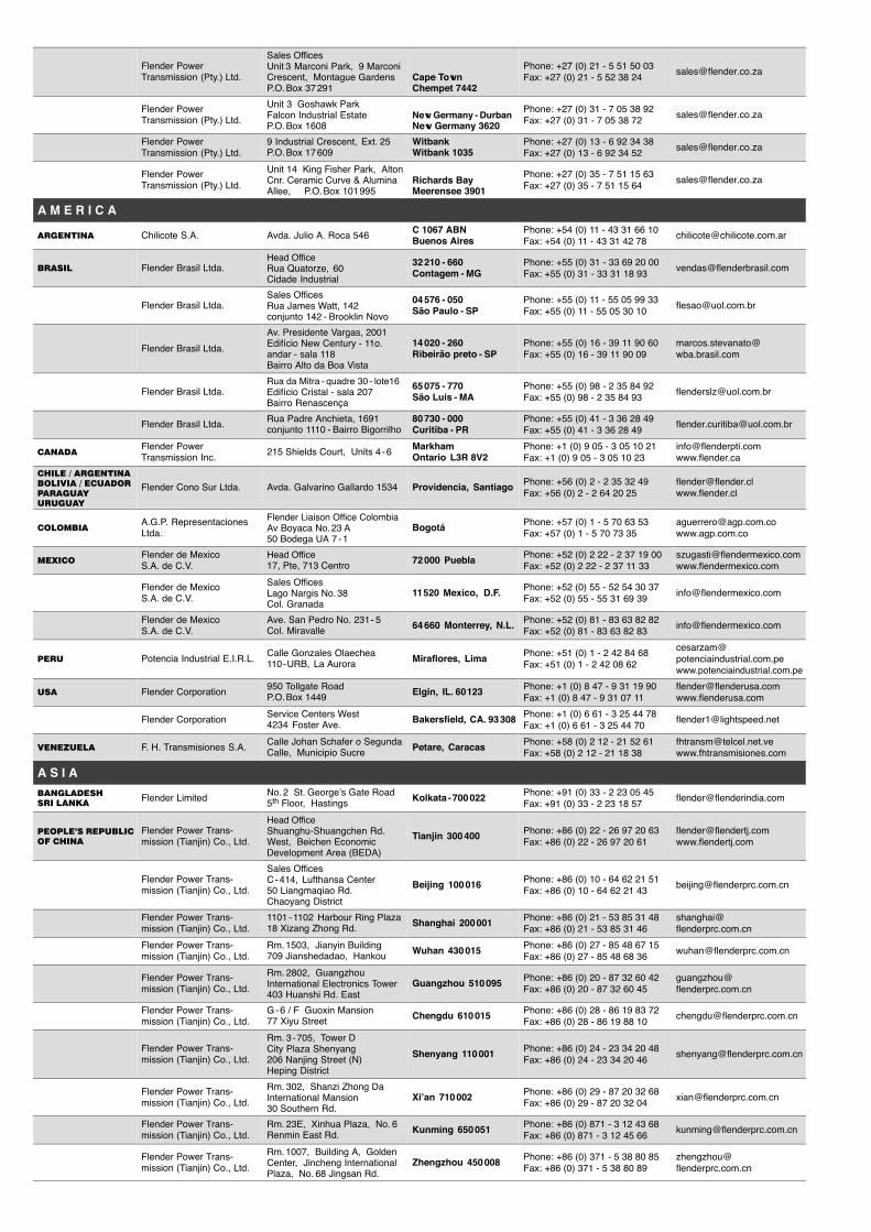
Flender PowerTransmission (Pty.) Ltd.
Sales OfficesUnit 3 Marconi Park, 9 MarconiCrescent, Montague GardensP.O. Box 37 291
Cape TownChempet 7442
Phone: +27 (0) 21 - 5 51 50 03Fax: +27 (0) 21 - 5 52 38 24
Flender PowerTransmission (Pty.) Ltd.
Unit 3 Goshawk ParkFalcon Industrial EstateP.O. Box 1608
New Germany - DurbanNew Germany 3620
Phone: +27 (0) 31 - 7 05 38 92Fax: +27 (0) 31 - 7 05 38 72
Flender PowerTransmission (Pty.) Ltd.
9 Industrial Crescent, Ext. 25P.O. Box 17 609
WitbankWitbank 1035
Phone: +27 (0) 13 - 6 92 34 38Fax: +27 (0) 13 - 6 92 34 52
Flender PowerTransmission (Pty.) Ltd.
Unit 14 King Fisher Park, AltonCnr. Ceramic Curve & AluminaAllee, P.O. Box 101 995
Richards BayMeerensee 3901
Phone: +27 (0) 35 - 7 51 15 63Fax: +27 (0) 35 - 7 51 15 64
A M E R I C A
�������� Chilicote S.A. Avda. Julio A. Roca 546C 1067 ABNBuenos Aires
Phone: +54 (0) 11 - 43 31 66 10Fax: +54 (0) 11 - 43 31 42 78
����� Flender Brasil Ltda.Head OfficeRua Quatorze, 60Cidade Industrial
32 210 - 660Contagem - MG
Phone: +55 (0) 31 - 33 69 20 00Fax: +55 (0) 31 - 33 31 18 93
Flender Brasil Ltda.Sales OfficesRua James Watt, 142conjunto 142 - Brooklin Novo
04 576 - 050São Paulo - SP
Phone: +55 (0) 11 - 55 05 99 33Fax: +55 (0) 11 - 55 05 30 10
Flender Brasil Ltda.
Av. Presidente Vargas, 2001Edifício New Century - 11o.andar - sala 118Bairro Alto da Boa Vista
14 020 - 260Ribeirão preto - SP
Phone: +55 (0) 16 - 39 11 90 60Fax: +55 (0) 16 - 39 11 90 09
Flender Brasil Ltda.Rua da Mitra - quadre 30 - lote16Edifício Cristal - sala 207Bairro Renascença
65 075 - 770São Luis - MA
Phone: +55 (0) 98 - 2 35 84 92Fax: +55 (0) 98 - 2 35 84 93
Flender Brasil Ltda.Rua Padre Anchieta, 1691conjunto 1110 - Bairro Bigorrilho
80 730 - 000Curitiba - PR
Phone: +55 (0) 41 - 3 36 28 49Fax: +55 (0) 41 - 3 36 28 49
������Flender PowerTransmission Inc.
215 Shields Court, Units 4 - 6MarkhamOntario L3R 8V2
Phone: +1 (0) 9 05 - 3 05 10 21Fax: +1 (0) 9 05 - 3 05 10 23
���� � ��������
������ � �������
�������
������
Flender Cono Sur Ltda. Avda. Galvarino Gallardo 1534 Providencia, Santiago Phone: +56 (0) 2 - 2 35 32 49Fax: +56 (0) 2 - 2 64 20 25
�������A.G.P. RepresentacionesLtda.
Flender Liaison Office ColombiaAv Boyaca No. 23 A50 Bodega UA 7 - 1
Bogotá Phone: +57 (0) 1 - 5 70 63 53Fax: +57 (0) 1 - 5 70 73 35
�� ���Flender de MexicoS.A. de C.V.
Head Office17, Pte, 713 Centro
72 000 Puebla Phone: +52 (0) 2 22 - 2 37 19 00Fax: +52 (0) 2 22 - 2 37 11 33
Flender de MexicoS.A. de C.V.
Sales OfficesLago Nargis No. 38Col. Granada
11 520 Mexico, D.F. Phone: +52 (0) 55 - 52 54 30 37Fax: +52 (0) 55 - 55 31 69 39
Flender de MexicoS.A. de C.V.
Ave. San Pedro No. 231 - 5Col. Miravalle
64 660 Monterrey, N.L. Phone: +52 (0) 81 - 83 63 82 82Fax: +52 (0) 81 - 83 63 82 83
���� Potencia Industrial E.I.R.L.Calle Gonzales Olaechea110 - URB, La Aurora
Miraflores, Lima Phone: +51 (0) 1 - 2 42 84 68Fax: +51 (0) 1 - 2 42 08 62
��� Flender Corporation950 Tollgate RoadP.O. Box 1449
Elgin, IL. 60 123 Phone: +1 (0) 8 47 - 9 31 19 90Fax: +1 (0) 8 47 - 9 31 07 11
Flender CorporationService Centers West4234 Foster Ave.
Bakersfield, CA. 93 308 Phone: +1 (0) 6 61 - 3 25 44 78Fax: +1 (0) 6 61 - 3 25 44 70
�������� F. H. Transmisiones S.A.Calle Johan Schafer o SegundaCalle, Municipio Sucre
Petare, Caracas Phone: +58 (0) 2 12 - 21 52 61Fax: +58 (0) 2 12 - 21 18 38
A S I A
��������
��� ����Flender Limited
No. 2 St. George’s Gate Road5th Floor, Hastings
Kolkata - 700 022 Phone: +91 (0) 33 - 2 23 05 45Fax: +91 (0) 33 - 2 23 18 57
������� �������
�� �����
Flender Power Trans-mission (Tianjin) Co., Ltd.
Head OfficeShuanghu-Shuangchen Rd.West, Beichen EconomicDevelopment Area (BEDA)
Tianjin 300 400 Phone: +86 (0) 22 - 26 97 20 63Fax: +86 (0) 22 - 26 97 20 61
Flender Power Trans-mission (Tianjin) Co., Ltd.
Sales OfficesC - 414, Lufthansa Center50 Liangmaqiao Rd.Chaoyang District
Beijing 100 016 Phone: +86 (0) 10 - 64 62 21 51Fax: +86 (0) 10 - 64 62 21 43
Flender Power Trans-mission (Tianjin) Co., Ltd.
1101 - 1102 Harbour Ring Plaza18 Xizang Zhong Rd.
Shanghai 200 001 Phone: +86 (0) 21 - 53 85 31 48Fax: +86 (0) 21 - 53 85 31 46
Flender Power Trans-mission (Tianjin) Co., Ltd.
Rm. 1503, Jianyin Building709 Jianshedadao, Hankou
Wuhan 430 015 Phone: +86 (0) 27 - 85 48 67 15Fax: +86 (0) 27 - 85 48 68 36
Flender Power Trans-mission (Tianjin) Co., Ltd.
Rm. 2802, GuangzhouInternational Electronics Tower403 Huanshi Rd. East
Guangzhou 510 095 Phone: +86 (0) 20 - 87 32 60 42Fax: +86 (0) 20 - 87 32 60 45
Flender Power Trans-mission (Tianjin) Co., Ltd.
G - 6 / F Guoxin Mansion77 Xiyu Street
Chengdu 610 015 Phone: +86 (0) 28 - 86 19 83 72Fax: +86 (0) 28 - 86 19 88 10
Flender Power Trans-mission (Tianjin) Co., Ltd.
Rm. 3 - 705, Tower DCity Plaza Shenyang206 Nanjing Street (N)Heping District
Shenyang 110 001 Phone: +86 (0) 24 - 23 34 20 48Fax: +86 (0) 24 - 23 34 20 46
Flender Power Trans-mission (Tianjin) Co., Ltd.
Rm. 302, Shanzi Zhong DaInternational Mansion30 Southern Rd.
Xi’an 710 002 Phone: +86 (0) 29 - 87 20 32 68Fax: +86 (0) 29 - 87 20 32 04
Flender Power Trans-mission (Tianjin) Co., Ltd.
Rm. 23E, Xinhua Plaza, No. 6Renmin East Rd.
Kunming 650 051 Phone: +86 (0) 871 - 3 12 43 68Fax: +86 (0) 871 - 3 12 45 66
Flender Power Trans-mission (Tianjin) Co., Ltd.
Rm. 1007, Building A, GoldenCenter, Jincheng InternationalPlaza, No. 68 Jingsan Rd.
Zhengzhou 450 008 Phone: +86 (0) 371 - 5 38 80 85Fax: +86 (0) 371 - 5 38 80 89
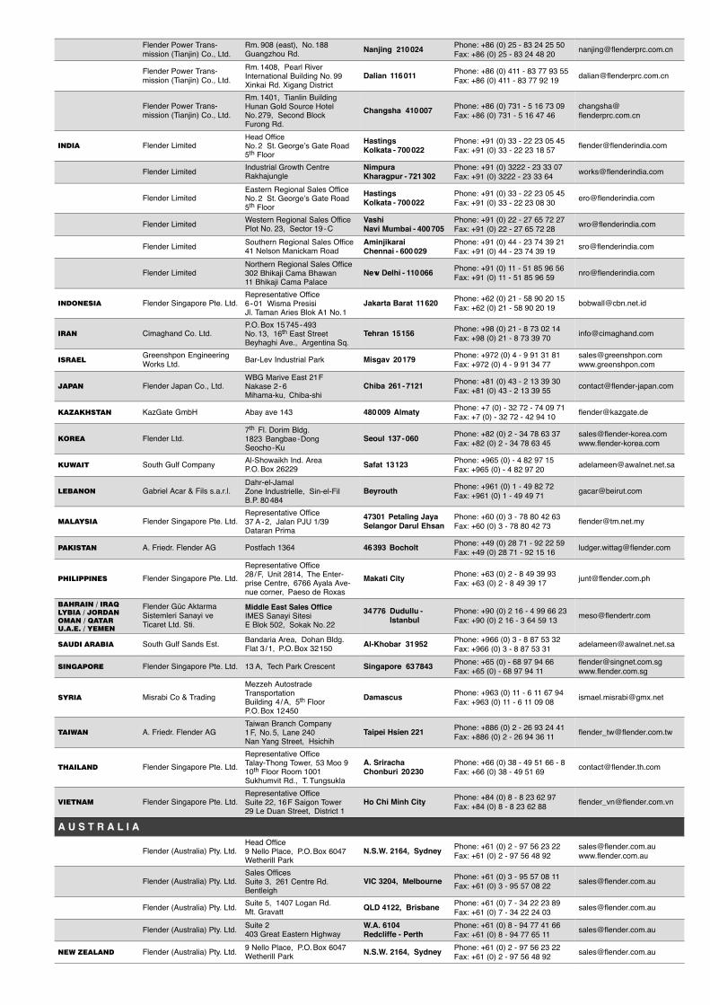
Flender Power Trans-mission (Tianjin) Co., Ltd.
Rm. 908 (east), No. 188Guangzhou Rd.
Nanjing 210 024 Phone: +86 (0) 25 - 83 24 25 50Fax: +86 (0) 25 - 83 24 48 20
Flender Power Trans-mission (Tianjin) Co., Ltd.
Rm. 1408, Pearl RiverInternational Building No. 99Xinkai Rd. Xigang District
Dalian 116 011 Phone: +86 (0) 411 - 83 77 93 55Fax: +86 (0) 411 - 83 77 92 19
Flender Power Trans-mission (Tianjin) Co., Ltd.
Rm. 1401, Tianlin BuildingHunan Gold Source HotelNo. 279, Second BlockFurong Rd.
Changsha 410 007 Phone: +86 (0) 731 - 5 16 73 09Fax: +86 (0) 731 - 5 16 47 46
����� Flender LimitedHead OfficeNo. 2 St. George’s Gate Road5th Floor
HastingsKolkata - 700 022
Phone: +91 (0) 33 - 22 23 05 45Fax: +91 (0) 33 - 22 23 18 57
Flender LimitedIndustrial Growth CentreRakhajungle
NimpuraKharagpur - 721 302
Phone: +91 (0) 3222 - 23 33 07Fax: +91 (0) 3222 - 23 33 64
Flender LimitedEastern Regional Sales OfficeNo. 2 St. George’s Gate Road5th Floor
HastingsKolkata - 700 022
Phone: +91 (0) 33 - 22 23 05 45Fax: +91 (0) 33 - 22 23 08 30
Flender LimitedWestern Regional Sales OfficePlot No. 23, Sector 19 - C
VashiNavi Mumbai - 400 705
Phone: +91 (0) 22 - 27 65 72 27Fax: +91 (0) 22 - 27 65 72 28
Flender LimitedSouthern Regional Sales Office41 Nelson Manickam Road
AminjikaraiChennai - 600 029
Phone: +91 (0) 44 - 23 74 39 21Fax: +91 (0) 44 - 23 74 39 19
Flender LimitedNorthern Regional Sales Office302 Bhikaji Cama Bhawan11 Bhikaji Cama Palace
New Delhi - 110 066 Phone: +91 (0) 11 - 51 85 96 56Fax: +91 (0) 11 - 51 85 96 59
��������� Flender Singapore Pte. Ltd.Representative Office6 - 01 Wisma PresisiJl. Taman Aries Blok A1 No. 1
Jakarta Barat 11 620 Phone: +62 (0) 21 - 58 90 20 15Fax: +62 (0) 21 - 58 90 20 19
���� Cimaghand Co. Ltd.P.O. Box 15 745 - 493No. 13, 16th East StreetBeyhaghi Ave., Argentina Sq.
Tehran 15 156 Phone: +98 (0) 21 - 8 73 02 14Fax: +98 (0) 21 - 8 73 39 70
�����Greenshpon EngineeringWorks Ltd.
Bar-Lev Industrial Park Misgav 20 179 Phone: +972 (0) 4 - 9 91 31 81Fax: +972 (0) 4 - 9 91 34 77
����� Flender Japan Co., Ltd.WBG Marive East 21 FNakase 2 - 6Mihama-ku, Chiba-shi
Chiba 261 - 7121 Phone: +81 (0) 43 - 2 13 39 30Fax: +81 (0) 43 - 2 13 39 55
���������� KazGate GmbH Abay ave 143 480 009 Almaty Phone: +7 (0) - 32 72 - 74 09 71Fax: +7 (0) - 32 72 - 42 94 10
����� Flender Ltd.7th Fl. Dorim Bldg.1823 Bangbae - DongSeocho - Ku
Seoul 137 - 060 Phone: +82 (0) 2 - 34 78 63 37Fax: +82 (0) 2 - 34 78 63 45
������ South Gulf CompanyAl-Showaikh Ind. AreaP.O. Box 26229
Safat 13 123 Phone: +965 (0) - 4 82 97 15Fax: +965 (0) - 4 82 97 20
������ Gabriel Acar & Fils s.a.r.l.Dahr-el-JamalZone Industrielle, Sin-el-FilB.P. 80 484
Beyrouth Phone: +961 (0) 1 - 49 82 72Fax: +961 (0) 1 - 49 49 71
������� Flender Singapore Pte. Ltd.Representative Office37 A - 2, Jalan PJU 1/39Dataran Prima
47301 Petaling JayaSelangor Darul Ehsan
Phone: +60 (0) 3 - 78 80 42 63Fax: +60 (0) 3 - 78 80 42 73
�������� A. Friedr. Flender AG Postfach 1364 46 393 Bocholt Phone: +49 (0) 28 71 - 92 22 59Fax: +49 (0) 28 71 - 92 15 16
���������� Flender Singapore Pte. Ltd.
Representative Office28 / F, Unit 2814, The Enter-prise Centre, 6766 Ayala Ave-nue corner, Paeso de Roxas
Makati City Phone: +63 (0) 2 - 8 49 39 93Fax: +63 (0) 2 - 8 49 39 17
������� � ����
���� � ������
���� � �����
������ � �����
Flender Güc AktarmaSistemleri Sanayi veTicaret Ltd. Sti.
Middle East Sales OfficeIMES Sanayi SitesiE Blok 502, Sokak No. 22
34 776 Dudullu -Istanbul
Phone: +90 (0) 2 16 - 4 99 66 23Fax: +90 (0) 2 16 - 3 64 59 13
����� ������ South Gulf Sands Est.Bandaria Area, Dohan Bldg.Flat 3 / 1, P.O. Box 32 150
Al-Khobar 31 952 Phone: +966 (0) 3 - 8 87 53 32Fax: +966 (0) 3 - 8 87 53 31
�������� Flender Singapore Pte. Ltd. 13 A, Tech Park Crescent Singapore 63 7843 Phone: +65 (0) - 68 97 94 66Fax: +65 (0) - 68 97 94 11
����� Misrabi Co & Trading
Mezzeh AutostradeTransportationBuilding 4 / A, 5th FloorP.O. Box 12 450
Damascus Phone: +963 (0) 11 - 6 11 67 94Fax: +963 (0) 11 - 6 11 09 08
������ A. Friedr. Flender AGTaiwan Branch Company1 F, No. 5, Lane 240Nan Yang Street, Hsichih
Taipei Hsien 221 Phone: +886 (0) 2 - 26 93 24 41Fax: +886 (0) 2 - 26 94 36 11
������� Flender Singapore Pte. Ltd.
Representative OfficeTalay-Thong Tower, 53 Moo 910th Floor Room 1001Sukhumvit Rd., T. Tungsukla
A. SrirachaChonburi 20 230
Phone: +66 (0) 38 - 49 51 66 - 8Fax: +66 (0) 38 - 49 51 69
������� Flender Singapore Pte. Ltd.Representative OfficeSuite 22, 16 F Saigon Tower29 Le Duan Street, District 1
Ho Chi Minh City Phone: +84 (0) 8 - 8 23 62 97Fax: +84 (0) 8 - 8 23 62 88
A U S T R A L I A
Flender (Australia) Pty. Ltd.Head Office9 Nello Place, P.O. Box 6047Wetherill Park
N.S.W. 2164, Sydney Phone: +61 (0) 2 - 97 56 23 22Fax: +61 (0) 2 - 97 56 48 92
Flender (Australia) Pty. Ltd.Sales OfficesSuite 3, 261 Centre Rd.Bentleigh
VIC 3204, Melbourne Phone: +61 (0) 3 - 95 57 08 11Fax: +61 (0) 3 - 95 57 08 22
Flender (Australia) Pty. Ltd.Suite 5, 1407 Logan Rd.Mt. Gravatt
QLD 4122, Brisbane Phone: +61 (0) 7 - 34 22 23 89Fax: +61 (0) 7 - 34 22 24 03
Flender (Australia) Pty. Ltd.Suite 2403 Great Eastern Highway
W.A. 6104Redcliffe - Perth
Phone: +61 (0) 8 - 94 77 41 66Fax: +61 (0) 8 - 94 77 65 11
��� ������ Flender (Australia) Pty. Ltd.9 Nello Place, P.O. Box 6047Wetherill Park
N.S.W. 2164, Sydney Phone: +61 (0) 2 - 97 56 23 22Fax: +61 (0) 2 - 97 56 48 92


A. Friedr. Flender AG · Alfred-Flender-Strasse 77 · 46395 BocholtPhone: +49(0)2871-920 · Fax: +49(0)2871-922596 · www.flender.comK
228
DE
/EN
/FR
200
5-04