Embed Size (px)
Citation preview

8
Kollo2002_e.book Seite 105 Mittwoch, 6. März 2002 5:26 17

Kollo2002_e.book Seite 106 Mittwoch, 6. März 2002 5:26 17
107LuK SYMPOSIUM 2002
The Crank-CVTMore economical than a manual transmission and more comfortable than a conventional CVT?
Oswald FriedmannWolfgang HaasUlrich Mair
8
Kollo2002_e.book Seite 107 Mittwoch, 6. März 2002 5:26 17
8 The Crank-CVT
108 LuK SYMPOSIUM 2002
IntroductionHardly conceivable that such a transmissioncould exist. But LuK sees a glimmer of hopeof achieving such an ambitious aim. This hasrequired an unconventional approach, whichwill result in a new transmission concept withnew and most probably unusual characteris-tics.
Presently the only choice a car buyer has isbetween the comfortable but expensive auto-matic transmission or the less expensive man-ual shift versions.
A costing exercise showed that on all existingproduction transmission types, considerableexpenditure is required to cope with drivingconditions, which although occurring onlyrarely, are still important. Start-off elementsand reverse gear account for a large propor-tion of transmission costs, particularly whenthe necessary associated hydraulic or elec-tromotive actuation is included.
On geared-neutral transmissions, such asfriction-wheel units, attempts have alreadybeen made to facilitate starting-off and revers-ing without the use of additional elements. Forthis, it must be able to slow the variator downto 0 1/min. Nevertheless, control problemsseem to be preventing exclusion of the start-off element. LuK has therefore sought a com-pletely different type of variator, which will al-low replacement of the loss-incurring start-offelement, the reverse gear and the fixed ratiogears.
This article presents a CVT with a variator thatoffers precisely these possibilities. Such aconcept transmission has already been builtby LuK and its basic functionality has beenproven. Indeed, initial trials in a vehicle havealready taken place.
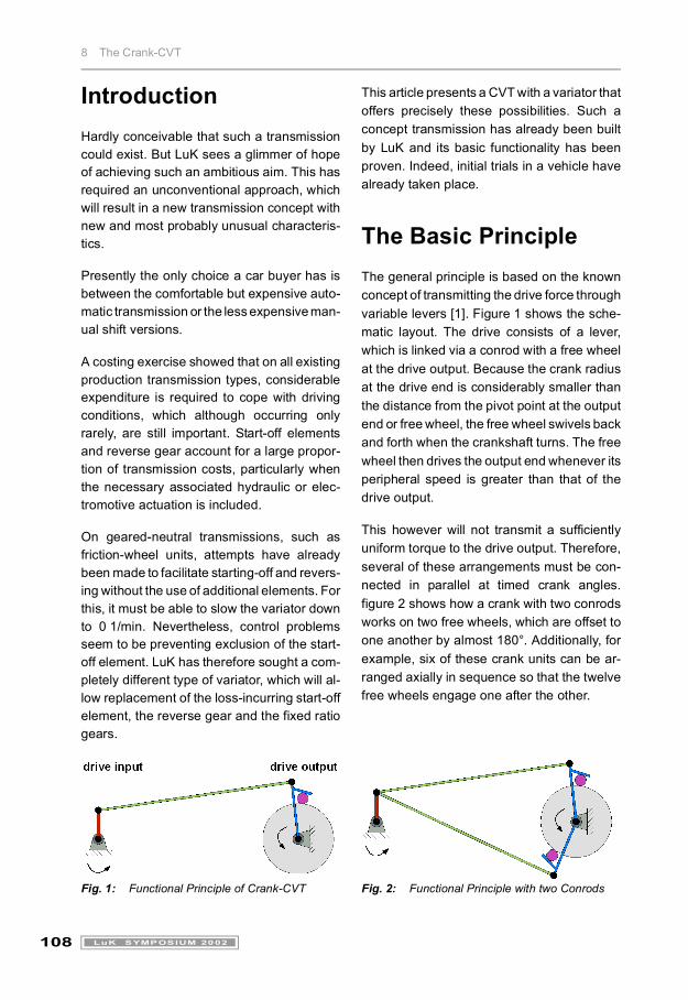
The Basic PrincipleThe general principle is based on the knownconcept of transmitting the drive force throughvariable levers [1]. Figure 1 shows the sche-matic layout. The drive consists of a lever,which is linked via a conrod with a free wheelat the drive output. Because the crank radiusat the drive end is considerably smaller thanthe distance from the pivot point at the outputend or free wheel, the free wheel swivels backand forth when the crankshaft turns. The freewheel then drives the output end whenever itsperipheral speed is greater than that of thedrive output.
This however will not transmit a sufficientlyuniform torque to the drive output. Therefore,several of these arrangements must be con-nected in parallel at timed crank angles.figure 2 shows how a crank with two conrodsworks on two free wheels, which are offset toone another by almost 180°. Additionally, forexample, six of these crank units can be ar-ranged axially in sequence so that the twelvefree wheels engage one after the other.
Fig. 1: Functional Principle of Crank-CVT Fig. 2: Functional Principle with two Conrods
Kollo2002_e.book Seite 108 Mittwoch, 6. März 2002 5:26 17
8 The Crank-CVT
109LuK SYMPOSIUM 2002
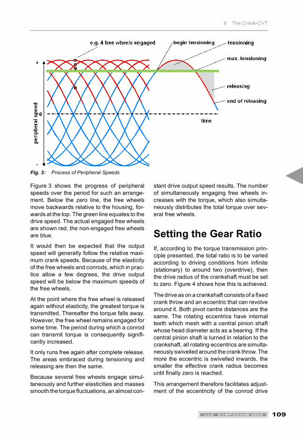
Fig. 3: Process of Peripheral Speeds
Figure 3 shows the progress of peripheralspeeds over the period for such an arrange-ment. Below the zero line, the free wheelsmove backwards relative to the housing, for-wards at the top. The green line equates to thedrive speed. The actual engaged free wheelsare shown red, the non-engaged free wheelsare blue.
It would then be expected that the outputspeed will generally follow the relative maxi-mum crank speeds. Because of the elasticityof the free wheels and conrods, which in prac-tice allow a few degrees, the drive outputspeed will be below the maximum speeds ofthe free wheels.
At the point where the free wheel is releasedagain without elasticity, the greatest torque istransmitted. Thereafter the torque falls away.However, the free wheel remains engaged forsome time. The period during which a conrodcan transmit torque is consequently signifi-cantly increased.
It only runs free again after complete release.The areas embraced during tensioning andreleasing are then the same.
Because several free wheels engage simul-taneously and further elasticities and massessmooth the torque fluctuations, an almost con-
stant drive output speed results. The numberof simultaneously engaging free wheels in-creases with the torque, which also simulta-neously distributes the total torque over sev-eral free wheels.
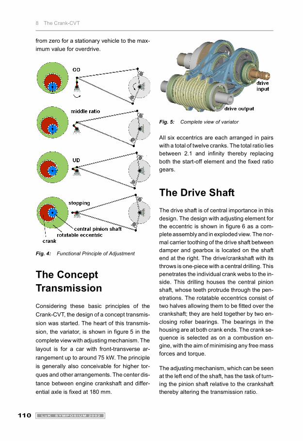
Setting the Gear RatioIf, according to the torque transmission prin-ciple presented, the total ratio is to be variedaccording to driving conditions from infinite(stationary) to around two (overdrive), thenthe drive radius of the crankshaft must be setto zero. Figure 4 shows how this is achieved.
The drive as on a crankshaft consists of a fixedcrank throw and an eccentric that can revolvearound it. Both pivot centre distances are thesame. The rotating eccentrics have internalteeth which mesh with a central pinion shaftwhose head diameter acts as a bearing. If thecentral pinion shaft is turned in relation to thecrankshaft, all rotating eccentrics are simulta-neously swivelled around the crank throw. Themore the eccentric is swivelled inwards, thesmaller the effective crank radius becomesuntil finally zero is reached.
This arrangement therefore facilitates adjust-ment of the eccentricity of the conrod drive
Kollo2002_e.book Seite 109 Mittwoch, 6. März 2002 5:26 17
8 The Crank-CVT
110 LuK SYMPOSIUM 2002
from zero for a stationary vehicle to the max-imum value for overdrive.
Fig. 4: Functional Principle of Adjustment
The Concept TransmissionConsidering these basic principles of theCrank-CVT, the design of a concept transmis-sion was started. The heart of this transmis-sion, the variator, is shown in figure 5 in thecomplete view with adjusting mechanism. Thelayout is for a car with front-transverse ar-rangement up to around 75 kW. The principleis generally also conceivable for higher tor-ques and other arrangements. The center dis-tance between engine crankshaft and differ-ential axle is fixed at 180 mm.
Fig. 5: Complete view of variator
All six eccentrics are each arranged in pairswith a total of twelve cranks. The total ratio liesbetween 2.1 and infinity thereby replacingboth the start-off element and the fixed ratiogears.
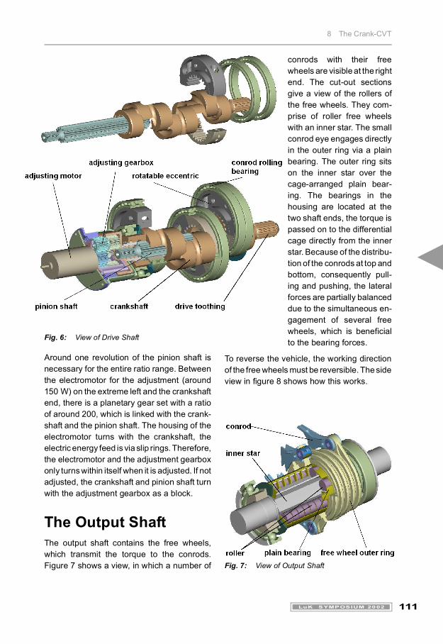
The Drive ShaftThe drive shaft is of central importance in thisdesign. The design with adjusting element forthe eccentric is shown in figure 6 as a com-plete assembly and in exploded view. The nor-mal carrier toothing of the drive shaft betweendamper and gearbox is located on the shaftend at the right. The drive/crankshaft with itsthrows is one-piece with a central drilling. Thispenetrates the individual crank webs to the in-side. This drilling houses the central pinionshaft, whose teeth protrude through the pen-etrations. The rotatable eccentrics consist oftwo halves allowing them to be fitted over thecrankshaft; they are held together by two en-closing roller bearings. The bearings in thehousing are at both crank ends. The crank se-quence is selected as on a combustion en-gine, with the aim of minimising any free massforces and torque.
The adjusting mechanism, which can be seenat the left end of the shaft, has the task of turn-ing the pinion shaft relative to the crankshaftthereby altering the transmission ratio.
Kollo2002_e.book Seite 110 Mittwoch, 6. März 2002 5:26 17
8 The Crank-CVT
111LuK SYMPOSIUM 2002
Fig. 6: View of Drive Shaft
Around one revolution of the pinion shaft isnecessary for the entire ratio range. Betweenthe electromotor for the adjustment (around150 W) on the extreme left and the crankshaftend, there is a planetary gear set with a ratioof around 200, which is linked with the crank-shaft and the pinion shaft. The housing of theelectromotor turns with the crankshaft, theelectric energy feed is via slip rings. Therefore,the electromotor and the adjustment gearboxonly turns within itself when it is adjusted. If notadjusted, the crankshaft and pinion shaft turnwith the adjustment gearbox as a block.
The Output ShaftThe output shaft contains the free wheels,which transmit the torque to the conrods.Figure 7 shows a view, in which a number of
conrods with their freewheels are visible at the rightend. The cut-out sectionsgive a view of the rollers ofthe free wheels. They com-prise of roller free wheelswith an inner star. The smallconrod eye engages directlyin the outer ring via a plainbearing. The outer ring sitson the inner star over thecage-arranged plain bear-ing. The bearings in thehousing are located at thetwo shaft ends, the torque ispassed on to the differentialcage directly from the innerstar. Because of the distribu-tion of the conrods at top andbottom, consequently pull-ing and pushing, the lateralforces are partially balanceddue to the simultaneous en-gagement of several freewheels, which is beneficialto the bearing forces.
To reverse the vehicle, the working directionof the free wheels must be reversible. The sideview in figure 8 shows how this works.
Fig. 7: View of Output Shaft
Kollo2002_e.book Seite 111 Mittwoch, 6. März 2002 5:26 17
8 The Crank-CVT
112 LuK SYMPOSIUM 2002
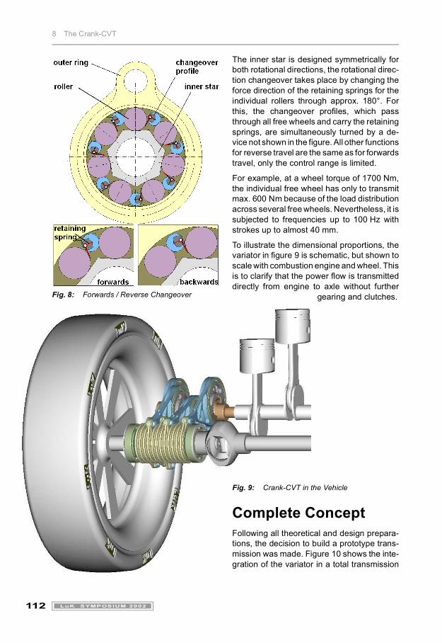
Fig. 8: Forwards / Reverse Changeover
The inner star is designed symmetrically forboth rotational directions, the rotational direc-tion changeover takes place by changing theforce direction of the retaining springs for theindividual rollers through approx. 180°. Forthis, the changeover profiles, which passthrough all free wheels and carry the retainingsprings, are simultaneously turned by a de-vice not shown in the figure. All other functionsfor reverse travel are the same as for forwardstravel, only the control range is limited.
For example, at a wheel torque of 1700 Nm,the individual free wheel has only to transmitmax. 600 Nm because of the load distributionacross several free wheels. Nevertheless, it issubjected to frequencies up to 100 Hz withstrokes up to almost 40 mm.
To illustrate the dimensional proportions, thevariator in figure 9 is schematic, but shown toscale with combustion engine and wheel. Thisis to clarify that the power flow is transmitteddirectly from engine to axle without further
gearing and clutches.
Fig. 9: Crank-CVT in the Vehicle
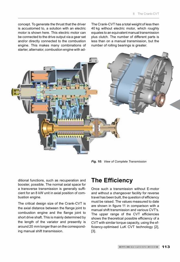
Complete ConceptFollowing all theoretical and design prepara-tions, the decision to build a prototype trans-mission was made. Figure 10 shows the inte-gration of the variator in a total transmission
Kollo2002_e.book Seite 112 Mittwoch, 6. März 2002 5:26 17
8 The Crank-CVT
113LuK SYMPOSIUM 2002
concept. To generate the thrust that the driveris accustomed to, a solution with an electricmotor is shown here. This electric motor canbe connected to the drive output via a gear setand/or directly connected to the combustionengine. This makes many combinations ofstarter, alternator, combustion engine with ad-
The Crank-CVT has a total weight of less then40 kg without electric motor, which roughlyequates to an equivalent manual transmissionplus clutch. The number of different parts isless than on a manual transmission, but thenumber of rolling bearings is greater.
ditional functions, such as recuperation andbooster, possible. The normal axial space fora transverse transmission is generally suffi-cient for an 8 kW unit in axial position of com-bustion engine.
The critical design size of the Crank-CVT isthe axial distance between the flange joint tocombustion engine and the flange joint toshort drive shaft. This is mainly determined bythe length of the variator and presently isaround 20 mm longer than on the correspond-ing manual shift transmission.
Fig. 10: View of Complete Transmission
The EfficiencyOnce such a transmission without E-motorand without a changeover facility for reversetravel has been built, the question of efficiencymust be raised. The values measured to dateare shown in figure 11 in comparison with amanual shift transmission and various CVT's.The upper range of the CVT efficienciesshows the theoretical possible efficiency of aCVT with similar torque capacity, using the ef-ficiency-optimised LuK CVT technology [2],[3].
Kollo2002_e.book Seite 113 Mittwoch, 6. März 2002 5:26 17
8 The Crank-CVT
114 LuK SYMPOSIUM 2002
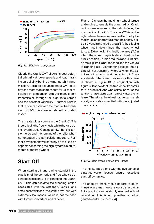
Fig. 11: Efficiency Comparison
Clearly the Crank-CVT shows its best poten-tial primarily at lower speeds and loads, trail-ing only slightly behind the manual shift trans-mission. It can be assumed that a CVT of to-day can more than compensate for its poor ef-ficiency in comparison with the manual shifttransmission through the high ratio spreadand the constant variability. A further point isthat in comparison with the manual transmis-sion or CVT there are no start-off and shiftlosses.
The greatest loss source in the Crank-CVT istheoretically the free wheels while they are be-ing overhauled. Consequently, the pre-ten-sion force and the running of the roller whennot engaged are particularly important. Fur-ther development will certainly be focused onaspects concerning the high dynamic require-ments of the free wheel.
Start-OffWhen starting-off and during standstill, theelasticity of the conrods and free wheels de-scribed in section 2 is of benefit to the Crank-CVT. This can alleviate the creeping motionassociated with the stationary vehicle andsmall eccentricities of the crank drive, and withextremely low losses, which is not the casewith torque converters and clutches.
Figure 12 shows the maximum wheel torqueand engine torque via the crank radius. Crankradius zero equates to the ratio infinite, themax. radius of the OD. The area (‘C’) is on theright, where the maximum wheel torque by themaximum engine torque times the effective ra-tio is given. In the middle area (‘B’), the slippingwheel itself determines the max. wheeltorque. Extreme right is finally the area (‘A’) inwhich the wheel torque is determined by thecrank position. In this area the ratio is infinite,as the slip limit is not reached and the vehicleis standing still. Disregarding losses the en-gine will not transmit any torque when the ac-celerator is pressed and the engine will freelyaccelerate. The speed process for this caseis shown in figure 13 in conjunction withfigure 3. It shows that the free wheel transmitstorque practically the whole time, because thetension phase starts again directly after the re-lease. Therefore, the wheel torque can be rel-atively accurately specified with the adjustedcrank radius.
Fig. 12: Max. Wheel and Engine Torque
The infinite ratio along with the avoidance ofclutch/converter losses ensure excellentstart-off dynamics.
The effective crank radius of zero is deter-mined with a mechanical stop, so that the in-finite position can be simply reached withoutregulation. This is not possible on othergeared-neutral concepts [4].
Kollo2002_e.book Seite 114 Mittwoch, 6. März 2002 5:26 17
8 The Crank-CVT
115LuK SYMPOSIUM 2002
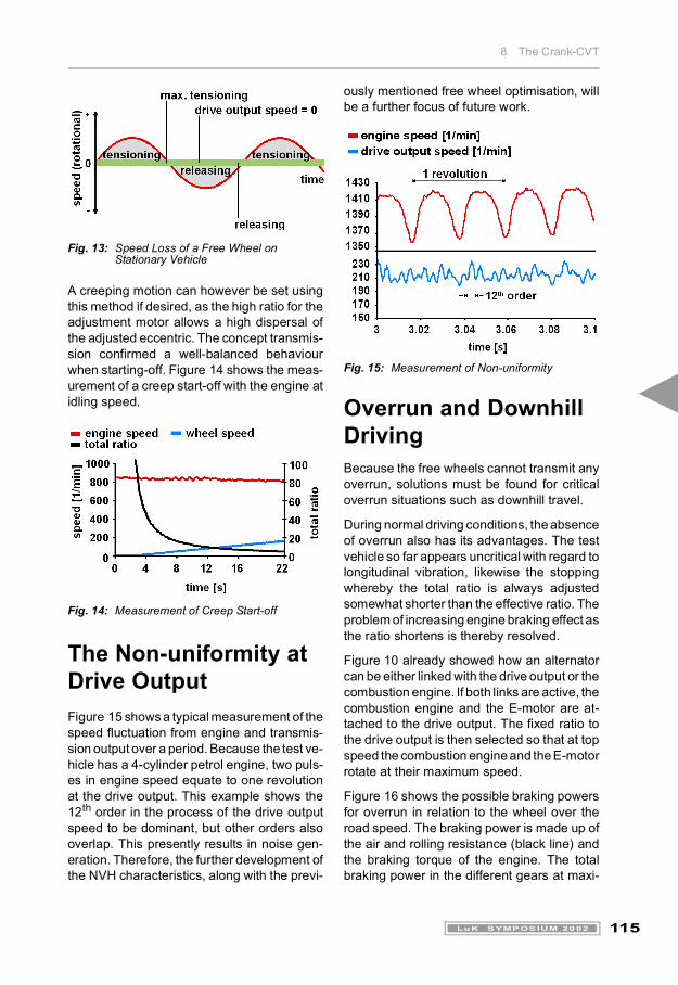
Fig. 13: Speed Loss of a Free Wheel on Stationary Vehicle
A creeping motion can however be set usingthis method if desired, as the high ratio for theadjustment motor allows a high dispersal ofthe adjusted eccentric. The concept transmis-sion confirmed a well-balanced behaviourwhen starting-off. Figure 14 shows the meas-urement of a creep start-off with the engine atidling speed.
Fig. 14: Measurement of Creep Start-off
The Non-uniformity at Drive OutputFigure 15 shows a typical measurement of thespeed fluctuation from engine and transmis-sion output over a period. Because the test ve-hicle has a 4-cylinder petrol engine, two puls-es in engine speed equate to one revolutionat the drive output. This example shows the12th order in the process of the drive outputspeed to be dominant, but other orders alsooverlap. This presently results in noise gen-eration. Therefore, the further development ofthe NVH characteristics, along with the previ-
ously mentioned free wheel optimisation, willbe a further focus of future work.
Fig. 15: Measurement of Non-uniformity
Overrun and Downhill DrivingBecause the free wheels cannot transmit anyoverrun, solutions must be found for criticaloverrun situations such as downhill travel.
During normal driving conditions, the absenceof overrun also has its advantages. The testvehicle so far appears uncritical with regard tolongitudinal vibration, likewise the stoppingwhereby the total ratio is always adjustedsomewhat shorter than the effective ratio. Theproblem of increasing engine braking effect asthe ratio shortens is thereby resolved.
Figure 10 already showed how an alternatorcan be either linked with the drive output or thecombustion engine. If both links are active, thecombustion engine and the E-motor are at-tached to the drive output. The fixed ratio tothe drive output is then selected so that at topspeed the combustion engine and the E-motorrotate at their maximum speed.
Figure 16 shows the possible braking powersfor overrun in relation to the wheel over theroad speed. The braking power is made up ofthe air and rolling resistance (black line) andthe braking torque of the engine. The totalbraking power in the different gears at maxi-
Kollo2002_e.book Seite 115 Mittwoch, 6. März 2002 5:26 17
8 The Crank-CVT
116 LuK SYMPOSIUM 2002
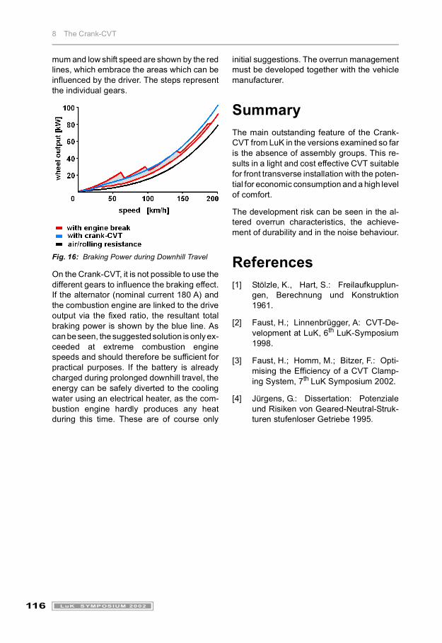
mum and low shift speed are shown by the redlines, which embrace the areas which can beinfluenced by the driver. The steps representthe individual gears.
Fig. 16: Braking Power during Downhill Travel
On the Crank-CVT, it is not possible to use thedifferent gears to influence the braking effect.If the alternator (nominal current 180 A) andthe combustion engine are linked to the driveoutput via the fixed ratio, the resultant totalbraking power is shown by the blue line. Ascan be seen, the suggested solution is only ex-ceeded at extreme combustion enginespeeds and should therefore be sufficient forpractical purposes. If the battery is alreadycharged during prolonged downhill travel, theenergy can be safely diverted to the coolingwater using an electrical heater, as the com-bustion engine hardly produces any heatduring this time. These are of course only
initial suggestions. The overrun managementmust be developed together with the vehiclemanufacturer.
SummaryThe main outstanding feature of the Crank-CVT from LuK in the versions examined so faris the absence of assembly groups. This re-sults in a light and cost effective CVT suitablefor front transverse installation with the poten-tial for economic consumption and a high levelof comfort.
The development risk can be seen in the al-tered overrun characteristics, the achieve-ment of durability and in the noise behaviour.
References[1] Stölzle, K., Hart, S.: Freilaufkupplun-
gen, Berechnung und Konstruktion1961.
[2] Faust, H.; Linnenbrügger, A: CVT-De-velopment at LuK, 6th LuK-Symposium1998.
[3] Faust, H.; Homm, M.; Bitzer, F.: Opti-mising the Efficiency of a CVT Clamp-ing System, 7th LuK Symposium 2002.
[4] Jürgens, G.: Dissertation: Potenzialeund Risiken von Geared-Neutral-Struk-turen stufenloser Getriebe 1995.
Kollo2002_e.book Seite 116 Mittwoch, 6. März 2002 5:26 17