Embed Size (px)
Citation preview
All
rights
rese
rved ©
WA
MG
RO
UP
WBH
CATALOGUE No. MA.04 M.
ISSUEA
DATE OF LATEST UPDATE
CREATION DATE
CIRCULATION100
MA
INT
EN
AN
CE
• MEZCLADORAS DISCONTINUAS DE REJA WBH
INSTALACIÓN, USO Y MANTENIMIENTO
• EINWELLEN-WURFSCHAUFELMISCHER FÜR
CHARGENBETRIEB WBH
EINBAU-, BETRIEBS- UND WARTUNGSANLEITUNG
• BATCH-TYPE PLOUGHSHARE MIXERS WBH
INSTALLATION, OPERATION AND MAINTENANCE
• MESCOLATORI DISCONTINUI A VOMERE WBH
INSTALLAZIONE, USO E MANUTENZIONE
2
12 / 2004
2
M. 3 → 4M. 5 → 89
WARTUNGSKATALOGBETRIEBS- UND WARTUNGSANLEITUNG - EINFÜHRUNG......BETRIEBS- UND WARTUNGSANLEITUNG.................................
CATÁLOGO DE MANTENIMIENTOUSO Y MANTENIMIENTO - INTRODUCCIÓN .......................USO Y MANTENIMIENTO ....................................................
CATALOGO DI MANUTENZIONEUSO E MANUTENZIONE - INTRODUZIONE...............................USO E MANUTENZIONE..............................................................
MAINTENANCE CATALOGUEOPERATION AND MAINTENANCE - INTRODUCTION.........OPERATION AND MAINTENANCE........................................
2
3
R.93949596979899100101102
ERSATZTEILKATALOGMISCHERGEHÄUSE...............................................................INSPEKTIONSKLAPPE.............................................................RUNDER ALAUSLAUF..............................................................MANUELLER PROBENEHMER................................................PNEUMATISCHER PROBENEHMER.......................................PNEUMATISCHER ANTRIEB FÜR AUSLAUFKLAPPE............ROTORWELLE..........................................................................ENDLAGERWELLENABDICHTUNG.........................................ENDLAGEREINHEIT ANTRIEBSSEITIG...................................ENDLAGEREINHEIT ABTRIEBSSEITIG...................................
CATÁLOGO DE REPUESTOSCUERPO MEZCLADORA .........................................................REGISTRO DE INSPECCIÓN ....................................................BOCA DE DESCARGA REDONDA ..........................................TOMA MUESTRA MANUAL .....................................................TOMA MUESTRA NEUMÁTICA ................................................ACTUADOR NEUMÁTICO BOCA DESCARGA .......................ROTOR .....................................................................................CIERRE SOPORTE DE EXTREMIDAD ......................................SOPORTE PARA ÁRBOL LADO MOTORIZACIÓN .................SOPORTE ÁRBOL LADO OPUESTO MOTORIZACIÓN ..........
CATALOGO PEZZI DI RICAMBIOCORPO MESCOLATORE.......................................................PORTELLO D’ISPEZIONE........................................................BOCCA DI SCARICO TONDA...................................................PRELIEVO CAMPIONE MANUALE..........................................PRELIEVO CAMPIONE PNEUMATICO....................................ATTUATORE PNEUMATICO BOCCA SCARICO......................ROTORE ..................................................................................TENUTA SUPPORTO ESTREMITA’.........................................SUPPORTO PER ALBERO LATO MOTORIZZAZIONE...........SUPPORTO ALBERO LATO OPPOSTO MOTORIZZAZIONE.
SPARE PARTS CATALOGUEMIXING SHELL......................................................................INSPECTION DOOR..............................................................ROUND OUTLET...................................................................MANUAL SAMPLE DRAW.....................................................PNEUMATIC SAMPLE DRAW...............................................PNEUMATIC OUTLET ACTUATOR.....................................ROTOR..................................................................................SHAFT SEAL END BEARING ASSEMBLY............................END BEARING ASSEMBLY DRIVE END.............................END BEARING ASSEMBLY OPPOSITE DRIVE END..........
3
12.04
MA.04.INDEX
-
-
-
-
WBH
ÍNDICE
INHALTSVERZEICHNIS
INDEX
INDICE
M. 3 → 4M. 5 → 89
R.93949596979899100101102
12.04
2
MA.04 M. 3
-
-
-
-
WBH
USO Y MANTENIMIENTO
BETRIEBS- UND WARTUNGSANLEITUNG
OPERATION AND MAINTENANCE
USO E MANUTENZIONE
ATTENZIONELa simbologia sopra riportata vie-ne utilizzata nel presente manua-le per richiamare l’attenzione dellettore sui punti od operazioni pe-ricolose per l’incolumità persona-le degli operatori.
Nota
Indica informazioni o procedureimportanti.
Il presente manuale non può es-sere riprodotto anche parzial-mente senza il consenso scrittodel Costruttore ed il suo conte-nuto non può essere utilizzatoper scopi non consentiti dal co-struttore.Ogni violazione sarà perseguitaa norma di legge.
WARNINGThe signal words shown aboveare used in this manual to call theuser’s attention to points or oper-ations dangerous for personalsafety of the operator.
Indicates important informationor procedures.
WARNINGFor clarity, some illustrationsin this manual show the ma-chine or parts of it with thepanels or casings removed.Do not use the machine inthis condition. Operate themachine only if all its guardsare in place.
Note
ATTENZIONEPer motivi di chiarezza alcuneillustrazioni del presente ma-nuale rappresentano la mac-china o parti di essa con pan-nelli o carter rimossi.Non utilizzare la macchina intali condizioni, ma solamentese provvista di tutte le sue pro-tezioni.
This manual may not be copied inpart or in whole without the priorwritten consent of the Manufac-turer. Its contents may not beused for purposes not permittedby the Manufacturer.All violations of this above cop-yright can give rise to prosecu-tion under law.
ATENCIÓNLa simbología presente aquí arri-ba se utiliza en el presente ma-nual para llamar la atención dellector sobre los puntos y lasoperaciones peligrosas para laincolumidad personal de losoperadores.
Nota
Indica informaciones o procedi-mientos importantes.
ATENCIÓNPara mayor claridad algunasilustraciones del presentemanual representan la má-quina o partes de la mismasin paneles o carter.No utilizar la máquina en ta-les condiciones, sino sola-mente si posee todas susprotecciones.
El presente manual no puede serreproducido ni siquiera parcial-mente sin el permiso escrito delFabricante y su contenido nopuede ser utilizado para usos nopermitidos por el mismo.Toda violación será punible porla ley.
ACHTUNGDieses Symbol wird in diesemHandbuch verwendet, um die Auf-merksamkeit des Lesers auf sol-che Stellen bzw. Arbeiten zu len-ken, die für die persönliche Si-cherheit der Bedieners gefähr-lich sind.
Anmerkung
Zeigt wichtige Informationen oderVerfahrensweisen an.
ACHTUNGDer Deutlichkeit halber werdendie Maschine bzw. ihre Kom-ponenten in einigen Abbildun-gen dieses Handbuchs mit ab-genommenen Schutzblechendargestellt.Betreiben Sie die Maschinenicht unter solchen Bedingun-gen, sondern nur dann, wennalle Schutzvorrichtungen mon-tiert sind.
Dieses Handbuch darf wederganz noch teilweise reproduziertwerden, wenn nicht die schriftli-che Genehmigung des Herstel-lers dazu vorliegt. Der Inhalt desHandbuches darf nicht zu Zwek-ken verwendet werden, die vomHerstellernicht genehmigt sind.Jede Zuwiderhandlung ist recht-lich strafbar.
- INTRODUCCIÓN
- EINFÜHRUNG
- INTRODUCTION
- INTRODUZIONE
12.04
2
-
-
-
-
WBH
USO Y MANTENIMIENTO
BETRIEBS- UND WARTUNGSANLEITUNG
OPERATION AND MAINTENANCE
USO E MANUTENZIONE MA.04 M. 4
CONSERVAZIONE ED UTILIZ-ZO DEL PRESENTE MANUALE
Scopo del presente manuale è diportare a conoscenza degli utiliz-zatori della macchina con testi efigure di chiarimento, le prescri-zioni e i criteri essenziali relativial trasporto alla movimentazione,all’uso e alla manutenzione dellamacchina stessa.
Leggere quindi attentamentequesto manuale prima di utilizza-re la macchina.Inoltre conservarlo con cura neipressi della macchina, in luogoprotetto ed asciutto, al riparo dairaggi del sole e comunque in luo-go facilmente e rapidamente rag-giungibile per ogni futura consul-tazione.
In casi di cessione della macchi-na, il presente manuale deve ac-compagnare la macchina stessa.
Il manuale rispecchia lo stato del-la tecnica al momento della com-mercializzazione della macchinae non può essere consideratoinadeguato se a seguito di nuo-ve esperienze ha subito succes-sivi aggiornamenti.A tale proposito il fabbricante siriserva il diritto di aggiornare laproduzione e i relativi manualisenza l’obbligo di aggiornare pro-duzioni e manuali precedenti, senon in casi eccezionali.
In caso di dubbio, consultare ilcentro di assistenza più vicino odirettamente la ditta costruttrice.Il costruttore è teso alla continuaottimizzazione del proprio prodot-to.Per tale motivo la ditta costruttri-ce è ben lieta di ogni segnalazio-ne o proposta tesa al migliora-mento del manuale e/o della mac-china.La macchina è stata consegnataall’utente alle condizioni di garan-zia valide al momento dell’acqui-sto.
Per ogni chiarimento contattare ilVostro rivenditore.
NotaIn caso di deterioramento del pre-sente manuale richiederne unacopia al Costruttore specificandoil numero di codice e l’edizioneriportate in copertina.
CONSERVING AND USING THISMANUAL
The purpose of this manual is toinform the user of this machineby means of texts and clear illus-trations, of the prescriptions andessential criteria for transport-ing, handling, use and mainte-nance of the machine.
Therefore, read this manual care-fully before using the machine.Keep it near the machine in a dryand protected place, away fromsunlight. However, it should beeasily and quickly reached forany consultation required.
If the machine is sold, do notforget to send this manual to thenew user.
This manual represents currentstate of the art when the machinewas first sold and cannot beregarded as inadequate if, on thebasis of new experience, newerversions show subsequent dif-ferences.The Manufacturer reserves theright to update his products andtheir manuals without beingobliged to update previous prod-ucts and their manuals, unless inexceptional cases.
In doubt, contact your closestauthorized Assistance Centre orthe Manufacturer.The Manufacturer strives contin-ually to optimize his product.In this context, any ideas or sug-gestions for the improvement ofthe product or the manual will bemost welcome.The machine is delivered to theuser under the warranty condi-tions in force at the time of pur-chase.
Please contact your dealer forany further information you maydesire.
NoteIn case of loss or deterioration ofthis manual, a new copy must berequested from the Manufactur-er, specifying the code numberand edition which can both befound on the cover.
CONSERVACIÓN Y UTILIZA-CIÓN DEL PRESENTE MANUAL
La finalidad del presente manuales de hacer conocer a los usua-rios de la máquina mediante tex-tos y figuras aclaratorias, lasprescripciones y los criteriosesenciales relativos al transpor-te, la manipulación, la utilizacióny el mantenimiento de la máquinamisma.
Leer por lo tanto atentamenteeste manual antes de utilizar lamáquina.Además conservarlo con cuida-do cerca de la máquina, en unlugar protegido y seco, fuera delalcance de los rayos solares ysobre todo fácil y rápidamenteaccesible para toda consultaciónfutura.
Si se cede la máquina, entregarel presente manual al nuevo pro-pietario.
El manual refleja el estado de latécnica en el momento de la co-mercialización de la máquina yno puede ser considerado inade-cuado si después de nuevasexperiencias ha sufrido sucesi-vas actualizaciones.A tal fin el fabricante se reservael derecho de actualizar la pro-ducción y los relativos manua-les sin la obligación de actuali-zar las producciones y manua-les previos, excepto para cier-tos casos excepcionales.
Si Usted tiene dudas, consulteel centro de asistencia más cer-cano o directamente el fabrican-te.El fabricante tiene como objetivola continua optimización de susproductos.Por esta razón el fabricanteaceptará con agrado toda indi-cación o propuesta orientada amejorar el manual y/o la máqui-na.La máquina ha sido entregada alusuario con las condiciones degarantía válidas en el momentode la compra.
Para cualquier aclaración con-tacte su concesionario vende-dor.
NotaEn caso de deterioramiento delpresente manual solicitar unacopia al Fabricante especifican-do el número de código y la edi-ción presentes en la portada.
AUFBEWAHRUNG UND VERWEN-DUNG DIESES HANDBUCHS
Der Zweck dieses Handbuchesist es, dem Betreiber der Maschi-ne mit erläuternden Texten undAbbildungen die Vorschriften undwesentlichen Kriterien für Trans-port, Handling, Betrieb und War-tung der Maschine mitzuteilen.
Lesen Sie dieses Handbuch da-her aufmerksam, bevor Sie dieMaschine in Betrieb nehmen.Heben Sie das Handbuch sorg-fältig in der Nähe der Maschinean einem geschützten und trok-kenen Ort auf, an dem es nichtder Sonneneinstrahlung ausge-setzt ist, jedoch schnell griffbereitist, wenn etwas nachgeschlagenwerden soll.
Wenn die Maschine den Besitzerwechselt, muß das Handbuch anden neuen Betreiber mitgeliefertwerden.
Das Handbuch entspricht demStand der Technik beim Erstver-kauf der Maschine und ist nichtals ungültig zu betrachten, wenninfolge neuer Erkenntnisse amMaschinenstandard der Nachfol-germodelle später Änderungenvorgenommen wurden.Der Hersteller behält sich in die-sem Zusammenhang vor, seineProduktion und die Handbücherauf den jeweils neuesten Standzu bringen, ohne dabei verpflich-tet zu sein, die zu früheren Zeitenhergestellten Produkte und Hand-bücher ebenfalls zu ändern, vonAusnahmen abgesehen.
Im Zweifelsfall wenden Sie sichan die nächste Kundenbertungs-stelle oder direkt an den Herstel-ler.Der Hersteller strebt nach ständi-ger Produktverbesserung.Aus diesem Grund sind Vorschlä-ge in bezug auf die Verbesserungdes Produktstandards und/oderder Dokumentation jederzeit will-kommen.Die Maschine wird dem Betreiberzu den Garantiebedingungen ge-liefert, die zum Zeitpunkt des Ver-kaufs gelten.
Für weitere Erläuterungen wen-den Sie sich an Ihren Händler.AnmerkungFordern Sie beim Hersteller unterAngabe des auf dem Deckblattangegebenen Codes sowie derAusgabenummer ein neues Ex-emplar des vorliegenden Hand-buches an, falls Ihre Kopie un-brauchbar geworden ist.
- INTRODUCCIÓN
- EINFÜHRUNG
- INTRODUCTION
- INTRODUZIONE
12.04
2
MA.04 M. 5
-
-
-
-
WBH
USO Y MANTENIMIENTO
BETRIEBS- UND WARTUNGSANLEITUNG
OPERATION AND MAINTENANCE
USO E MANUTENZIONE
NotaAcompañan al presente manuallos manuales de Uso y Manteni-miento de los componentes co-merciales y las tablas de identi-ficación mezclador.En caso de discordancias en lasoperaciones de mantenimientoentre nuestro manual y las delos componentes comerciales,atenerse a lo mencionado ennuestra publicación.
GARANTÍAPor ningún motivo el usuario estáautorizado a la modificación dela máquina.Por cada anomalía encontrada,dirigirse al más cercano centrode asistencia.Todo tentativo de desmontaje,modificación o en general de in-tervenciones no autorizadas encualquier componente de la má-quina por parte del usuario o porparte de personal no autoriza-do, invalidará la garantía y exo-nerará al fabricante de toda res-ponsabilidad por los eventualesdaños ya sea a personas o acosas que derivan de dicha mo-dificación.
El fabricante no se asume tam-poco ninguna eventual respon-sabilidad en los casos siguien-tes:- una instalación no correcta;- uso inapropiado de la máquina
por parte de personal no ca-pacitado adecuadamente;
- uso contrario a las normativasvigentes en el país de uso;
- mantenimiento carente o au-sente;
- uso de repuestos no originaleso no específicos para el mode-lo;
- incumplimiento total o parcial delas instrucciones.
NoteThis manual comes complete withthe Operating and MaintenanceManuals for the commercial com-ponents of the mixer and themixer identification chart.If there is disagreement betweenthe maintenance operations giv-en in our manual and the othermaterial given in the Annexes,the instructions in our manual arebinding.
WARRANTYThe user is not authorized totamper with the machine for anyreason whatsoever.Contact your nearest ServiceCentre for any problem, fault ordefect.Any attempt to dismantle, modifyor tamper with any component ofthe machine by the user or non-authorized personnel will cancelthe warranty and relieve the Man-ufacturer from any and all liabilityfor injury to persons or damageto things stemming from suchtampering.
The Manufacturer shall be re-lieved of all liability in the follow-ing situations:- incorrect installation;- improper use of the machine by
inadequately trained personnel;- use contrary to regulations in
force in the country where themachine is used;
- omitted or poor maintenance;- use of non-original spares or
not specific for the model;- total or partial non-compliance
with these instructions.
AnmerkungDiesem Handbuch liegen die Be-triebs- und Wartungsanleitungender Normteile sowie eine Tabellezur Identifikation des Mischersbei.Bei Nicht-Übereinstimmung zwi-schen den Wartungsvorschriftenaus unserem Handbuch und je-nen für die Normteile, sind dieaus unserem Handbuch als ver-bindlich zu betrachten.
GARANTIEDer Betreiber hat kein Recht dazu,an der Maschine Änderungenvorzunehmen.Bei Betriebsstörung aller Art mußsich der Betreiber an die nächsteKundendienststelle wenden.Jeder Versuch des Ausbaus, derÄnderung an der Maschine oderan Maschinenteilen durch den Be-treiber selbst oder durch dazunicht befugtes Personal führtumgehend zum Verlust des Ga-rantieanspruchs und enthebt denHersteller jeder Haftung für et-waige Sach- oder Personenschä-den, die sich aus der Verände-rung der ursprünglichen Konfigu-ration der Maschine ergeben.
Der Hersteller sieht sich in denfolgenden Fällen seiner Haftpflichtenthoben:- bei unsachgemäßem Einbau;- bei unsachgemäßer Anwen-
dung der Maschine seitens desPersonals, welches nicht ent-sprechend fachlich geschultwurde;
- bei Anwendungen, die mit dengesetzlichen Bestimmungendes jeweiligen Aufstellungslan-des nicht konform sind;
- bei nicht oder unsachgemäßausgeführter Wartung;
- bei Verwendung von Ersatztei-len, die keine Originalteile sindoder von Original-Ersatzteilen,die nicht speziell für das Modellbestimmt sind;
- bei völliger oder teilweiser Nicht-beachtung der in diesem Hand-buch enthaltenen Anleitungen.
NotaIl presente manuale è corredatocon i manuali di Uso e Manuten-zione dei componenti commer-ciali, delle tabelle di identificazio-ne mescolatore.Nel caso di discordanze nelleoperazioni di manutenzione tra ilnostro manuale e quelle dei com-ponenti commerciali, attenersi aquanto riportato nella nostra pub-blicazione.
GARANZIAPer nessun motivo l’utente è au-torizzato alla manomissione del-la macchina.Ad ogni anomalia riscontrata, ri-volgersi al più vicino centro di as-sistenza.Ogni tentativo di smontaggio, dimodifica o in generale di mano-missione di un qualsiasi compo-nente della macchina da partedell’utilizzatore o da personalenon autorizzato ne invaliderà lagaranzia e solleverà la ditta co-struttrice da ogni responsabilitàcirca gli eventuali danni sia a per-sone che a cose derivanti da talemanomissione.
Il fabbricante si ritiene altresì sol-levato da eventuali responsabili-tà nei seguenti casi:- una non corretta installazione;- uso improprio della macchina
da parte di personale non ad-destrato adeguatamente;
- uso contrario alle normative vi-genti nel paese di utilizzo;
- mancata o carente manuten-zione;
- utilizzo dei ricambi non originalio non specifici per il modello;
- inosservanza totale o parzialedelle istruzioni.
12.04
2
-
-
-
-
WBH
USO Y MANTENIMIENTO
BETRIEBS- UND WARTUNGSANLEITUNG
OPERATION AND MAINTENANCE
USO E MANUTENZIONE MA.04 M. 6
DESCRIZIONE DELLA MACCHINA
La macchina è stata progettata e realiz-zata nel rispetto della direttiva CE in vi-gore al momento della costruzione.E’ una macchina studiata per ottenere lamiscelazione, ed il trasporto dei prodotticaricati all’interno della camera del me-scolatore omogeneizzando il prodotto.E’ in grado di trattare una vasta gammadi prodotti.Per tale motivo il costruttore è in grado difornire la macchina in una vastissimagamma di versioni che si differenziano siadimensionalmente e costruttivamente.Per individuare il modello del mescolato-re in Vs possesso, consultare le tabelleallegate al presente manuale.
USO PREVISTO
Questo mescolatore è specificamenteprevisto per il trattamento di miscele inpolvere.E’ altresì possibile mescolare prodottipastosi, ma nella versione standard ilmescolatore non è idoneo al trattamen-to di miscele completamente liquide. Inquesti casi occorre specificarlo chiara-mente all’ordine della macchina per ot-tenere le modifiche necessarie.
USI NON CONSENTITI
Il mescolatore deve essere utilizzatosolamente per gli scopi espressamenteprevisti dal costruttore.Non utilizzare la macchina nel caso che:- non sia stata correttamente fissata a
terra.- Non siano state collegate correttamen-
te le tubazioni.- Non sia stata correttamente allacciata
alla rete elettrica.- Non sia stata correttamente collegata
all’impianto pneumatico.- Non utilizzare il mescolatore con uten-
sili non integri e non correttamenteaffilati.Si riduce la capacità di miscelazioneaumentando la coppia assorbita dalmotore elettrico.
- Non salire in piedi sulla macchina an-che se non funzionante. Oltre a rovino-se cadute, si rischia il danneggiamen-to del mescolatore.
- Non intervenire sul motore elettrico osu qualsiasi altro componente elettricosenza avere in precedenza scollegatola macchina dalla linea di alimentazio-ne elettrica per evitare il rischiodi folgorazione. Qualsiasi lavoro sul-l'impianto e sul motore elettricodeveessere effettuato soltanto dall'elettrici-sta.Non lavare la macchina dirigendo ilgetto d’acqua sulle parti elettriche.
- Non miscelare prodotti di dubbia com-posizione, aggressivi chimicamente, in-fiammabili o esplosivi, o comunquepericolosi per la macchina o per l’ope-ratore stesso.
- Non azionare il mescolatore con il con-tenitore in pressione o depressione.
- Non utilizzare la macchina in ambientidove esiste il pericolo di incendio o diesplosione.
- Non mettere in pressione o in depres-sione la camera di mescolazione, poi-chè la macchina non può operare in talicondizioni.
- Non superare la temperatura di +150°Cnel mescolatore-essicatore.
DESCRIPTION OF THE MACHINE
This machine has been designed andmanufactured in full compliance withCE standards in force at the time ofmanufacture.It has been designed to mix andconvey the materials loaded inside itsmixing chamber so that the product isperfectly mixed.It can handle a vast range of products.To this end, the Manufacturer cansupply the mixer in a full range ofversions that differ both in size anddesign.To identify the model of your mixer,refer to the tables annexed to thismanual.
DESIGNATED USE
This mixer has been designed specif-ically to handle material in powderfo rm.It can be used to handle moist mate-rial, but the standard version is notsuitable for working with completelyliquid mixtures. If the machine is tohandle this kind of material, this mustbe specified when the order is placedso that the necessary modificationscan be made.
USES NOT ALLOWED
The mixer may be used solely for thepurposes expressly envisioned bythe Manufacturer.Do not use the machine if:- it has not be anchored correctly to
the floor.- The pipe work has not been correctly
connected.- The connection to the mains electric
supply has not been done correctly.- The connection to the compressed
air supply has not been done cor-rect ly.
- The mixer has imperfect or not fullysharpened tools. This will reduce thegrinding capacity and increase thetorque absorbed by the motor.
- Do not climb on top of the mixereven if it is not working. Apart fromthe danger of falls, there is the realrisk of damaging the mixer.
- Do not work on the electric motorunless you have first disconnectedthe machine form the electric sup-ply source. Electric connections andall electric work must be carried outby qualified personnel only.There is a real risk of electrocution.
- Do not wash the machine using a jetof water that could come in contactwith electric parts.
- Do not use the machine to mixsuspicious materialseg, chemicallyaggressive, flammable, explosiveor dangerous for the machine or itsoperator.
- Do not operate the mixer with itschamber pressurized or under vac-uum.
- Do not use the machine in areaswhere there is risk of fire or explo-sion.
- Do not pressurize the mixing cham-ber or create a vacuum inside itbecause the machine must not beused in these conditions.
- Do not exceed a temperature of+150°C in the mixer for drying pur-poses.
BESCHREIBUNG DER MASCHINE
Die Maschine wurde unter Beachtung derbei der Fertigung der Maschine gelten-den CE-Richtlinien ausgelegt und gefer-tigt.Die Maschine dient dazu, die in die Misch-kammer aufgegebenen Produkte zu ver-mischen und gleichzeitig zu fördern, umein homogenes Mischgut zu erhalten.Die Maschine eignet sich zum Mischeneiner Vielzahl von Produkten.Der Hersteller ist in der Lage, unterschied-liche Versionen der Maschine zu liefern,die sich in Bauform und Baugröße von-einander unterscheiden.Zur Identifikation des von Ihnen erworbe-nen Mischermodells die diesem Hand-buch beiliegenden Tabellen verwenden.
VERWENDUNGSZWECK
Dieser Mischer ist speziell zur Behand-lung von Gemischen in Pulverform vorge-sehen.Es ist auch möglich, pastöse Produkte zumischen, aber in der Standardausführungeignet der Mischer sich nicht zur Behand-lung von gänzlich flüssigen Mischungen.In solchen Fällen muß den Verwendungs-zweck bei der Bestellung klar angegebenwerden, damit der Mischer entsprechendkonstruktiv abgeändert wird.
UNZULÄSSIGE VERWENDUNGEN
Der Mischer darf nur für die Einsatz-zwecke verwendet werden, die der Her-steller ausdrücklich vorgesehen hat.Die Maschine in den folgenden Fällennicht benutzen:- wenn sie nicht korrekt am Boden ver-
ankert ist.- Wenn die Versorgungsleitungen nicht
korrekt angeschlossen sind.- Wenn sie nicht korrekt an das Strom-
netz angeschlossen wurde.- Wenn sie nicht korrekt an die Druck-
luftversorgung angeschlossen wurde.- Den Mischer nicht in Betrieb nehmen,
wenn die Werkzeuge beschädigt oderstumpf sind, da das Zerkleinerungs-vermögen abnimmt, während dieStromaufnahme des Elektromotors an-steigt.
- Nicht auf den Mischer steigen, auchdann nicht, wenn er nicht läuft. Manriskiert nicht nur zu fallen und sichdabei zu verletzten, sondern auch, denMischer zu beschädigen.
- Nicht am Elektromotor oder an ande-ren elektrischen Teilen arbeiten, wennman nicht vorher die Stromversorgungdes Mischers ausgeschaltet hat, umkeinen elektrischen Schlag zu bekom-men. Elektroarbeiten nur vom Elektri-ker vornehmen lassen.Zum Waschen der Maschine nie denWasserschlauch auf die elektrischenBetriebsmittel richten.
- Keine Substanzen mischen, die einezweifelhafte Zusammensetzung ha-ben, die chemisch aggressiv, entflamm-bar oder explosiv sind oder gefährlichfür die Maschine oder den Bedienersein können.
- Den Mischer nicht betreiben, wenn dieMischkammer unter Druck oder Un-terdruck steht.
- Die Maschine nicht in feuer- oder ex-plosionsgefährdeten Räumen betrei-ben.
- In der Mischkammer darf sich wederein Über-, noch ein Unterdruck auf-bauen, weil die Maschine unter diesenBedingungen nicht arbeiten kann.
- Die Temperatur im Mischer darf zuTrocknungszwecken +150°C nichtübersteigen.
DESCRIPCIÓN DE LA MÁQUINA
La máquina ha sido proyectada y rea-lizada respetando la directiva CE envigor en el momento de la fabrica-ción.Es una máquina estudiada para obte-ner la mezcla y el transporte de losproductos cargados dentro de la cá-mara de la mezcladora, homogenei-zando el producto.Puede tratar una vasta gama de pro-ductos.Por tal motivo el fabricante puedesuministrar la máquina en una vastí-sima gama de versiones que se dife-rencian, como tamaño y/o como ca-racterísticas constructivas.Para identificar el modelo de la mez-cladora en su poder, consulte las ta-blas anexas al presente manual.
UTILIZACIÓN PREVISTAEsta mezcladora está específicamen-te realizada para el tratamiento demezclas en polvo.Es además posible mezclar produc-tos pastosos, pero en la versión es-tándar la mezcladora no es idóneapara tratar mezclas completamentelíquidas.En estos casos es necesario especi-ficarlo claramente en el momento delpedido para obtener las modificacio-nes oportunas.
USOS NO PERMITIDOSEsta máquina se debe utilizar sola-mente para las finalidades expresa-mente previstas por el fabricante.No utilizar la máquina en el caso que:- no haya sido fijada correctamente
al pavimento.- No hayan sido conectadas correc-
tamente las tuberías.- No haya sido conectada correcta-
mente con la red eléctrica.- No haya sido conectada correcta-
mente con la instalación neumáti-ca.
- No utilizar la mezcladora con útilesque no estén en perfecto estado yno estén correctamente afilados.Se reduce la capacidad de mezcla-do aumentando el par absorbido porel motor eléctrico.
- No subir sobre la máquina aún cuan-do no está en funcionamiento.Además de caídas perjudiciales, secorre el riesgo de dañar la mezcla-dora.
- No intervenir en el motor eléctrico oen cualquier otro componente eléc-trico sin previamente haber desco-nectado la máquina de la línea dealimentación eléctrica para evitarel riesgo de electrocución. Todo tra-bajo en la instalación o en el motoreléctrico debe efectuarlo solamen-te el electricista.No lavar la máquina orientando elchorro de agua hacia las partes eléc-tricas.
- No mezclar productos de dudosacomposición, químicamente agre-sivos, inflamables o explosivos, ode todos modos peligrosos para lamáquina o para el operador mismo.
- No accionar la mezcladora con elcontenedor bajo presión o en de-presión.
- No utilizar la máquina en ambientesdonde existe peligro de incendio ode explosión.
- No poner en presión o en depresiónla cámara de mezclado, ya que lamáquina no puede operar en dichascondiciones.
- No superar la temperatura de +150°Cen la mezcladora-secadora.
12.04
2
MA.04 M. 7
-
-
-
-
WBH
USO Y MANTENIMIENTO
BETRIEBS- UND WARTUNGSANLEITUNG
OPERATION AND MAINTENANCE
USO E MANUTENZIONE
DATI ANAGRAFICI
L’esatta citazione del modello delnumero di matricola e dell’anno
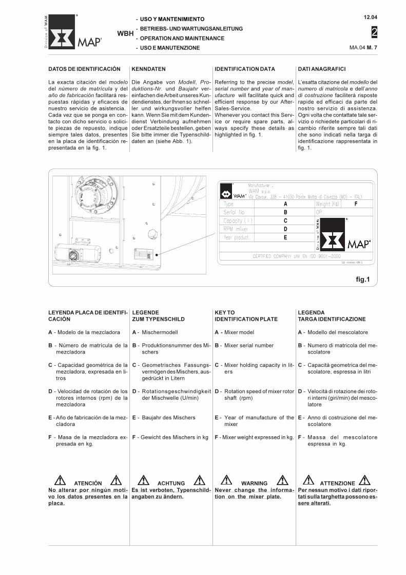
di costruzione faciliterà risposterapide ed efficaci da parte delnostro servizio di assistenza.Ogni volta che contattate tale ser-vizio o richiedete particolari di ri-cambio riferite sempre tali datiche sono indicati nella targa diidentificazione rappresentata infig. 1.
DATOS DE IDENTIFICACIÓN
La exacta citación del modelo
del número de matrícula y delaño de fabricación facilitará res-puestas rápidas y eficaces denuestro servicio de asistencia.Cada vez que se ponga en con-tacto con dicho servicio o solici-te piezas de repuesto, indiquesiempre tales datos, presentesen la placa de identificación re-presentada en la fig. 1.
KENNDATEN
Die Angabe von Modell, Pro-
duktions-Nr. und Baujahr ver-einfachen die Arbeit unseres Kun-dendienstes, der Ihnen so schnel-ler und wirkungsvoller helfenkann. Wenn Sie mit dem Kunden-dienst Verbindung aufnehmenoder Ersatzteile bestellen, gebenSie bitte immer die Typenschild-daten an (siehe Abb. 1).
IDENTIFICATION DATA
Referring to the precise model,serial number and year of man-
ufacture will facilitate quick andefficient response by our After-Sales-Service.Whenever you contact this Serv-ice or require spare parts, al-ways specify these details ashighlighted in fig. 1.
LEGENDATARGA IDENTIFICAZIONE
A - Modello del mescolatore
B - Numero di matricola del me-scolatore
C - Capacità geometrica del me-scolatore, espressa in litri
D - Velocità di rotazione dei roto-ri interni (giri/min) del mesco-latore
E - Anno di costruzione del me-scolatore
F - Massa del mescolatoreespressa in kg.
LEYENDA PLACA DE IDENTIFI-CACIÓN
A - Modelo de la mezcladora
B - Número de matrícula de lamezcladora
C - Capacidad geométrica de lamezcladora, expresada en li-tros
D - Velocidad de rotación de losrotores internos (rpm) de lamezcladora
E - Año de fabricación de la mez-cladora
F - Masa de la mezcladora ex-presada en kg.
LEGENDEZUM TYPENSCHILD
A - Mischermodell
B - Produktionsnummer des Mi-schers
C - Geometrisches Fassungs-vermögen des Mischers, aus-gedrückt in Litern
D - Rotationsgeschwindigkeitder Mischwelle (U/min)
E - Baujahr des Mischers
F - Gewicht des Mischers in kg
KEY TOIDENTIFICATION PLATE
A - Mixer model
B - Mixer serial number
C - Mixer holding capacity in lit-ers
D - Rotation speed of mixer rotorshaft (rpm)
E - Year of manufacture of themixer
F - Mixer weight expressed in kg.
ATTENZIONEPer nessun motivo i dati ripor-tati sulla targhetta possono es-sere alterati.
WARNINGNever change the informa-tion on the mixer plate.
ACHTUNGEs ist verboten, Typenschild-angaben zu ändern.
ATENCIÓNNo alterar por ningún moti-vo los datos presentes en laplaca.
•
fig.1
12.04
2
-
-
-
-
WBH
USO Y MANTENIMIENTO
BETRIEBS- UND WARTUNGSANLEITUNG
OPERATION AND MAINTENANCE
USO E MANUTENZIONE MA.04 M. 8
SISTEMI DI SICUREZZA
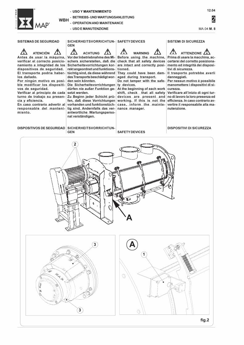
ATTENZIONEPrima di usare la macchina, ac-certarsi del corretto posiziona-mento ed integrità dei disposi-tivi di sicurezza.Il trasporto potrebbe averlidanneggiati.Per nessun motivo è possibilemanomettere i dispositivi di si-curezza.Verificare all’inizio di ogni tur-no di lavoro la loro presenza edefficienza. In caso contrario av-vertire il responsabile alla ma-nutenzione.
DISPOSITIVI DI SICUREZZA
SISTEMAS DE SEGURIDAD
ATENCIÓNAntes de usar la máquina,verificar el correcto posicio-namiento e integridad de losdispositivos de seguridad.El transporte podría haber-los dañado.Por ningún motivo es posi-ble modificar los dispositi-vos de seguridad.Verificar al principio de cadaturno de trabajo su presen-cia y eficiencia.En caso contrario advertir alresponsable del manteni-miento.
DISPOSITIVOS DE SEGURIDAD
SICHERHEITSVORRICHTUN-GEN
ACHTUNGVor der Inbetriebnahme des Mi-schers sicherstellen, daß dieSicherheitsvorrichtungen kor-rekt angeordnet und funktions-tüchtig sind, da diese währenddes Transports beschädigt wor-den sein könnten.Die Sicherheitsvorrichtungendürfen nie außer Funktion ge-setzt werden.Zu Beginn jeder Schicht prü-fen, daß diese Vorrichtungenvorhanden und funktionstüch-tig sind. Andernfalls das ver-antwortliche Wartungsperso-nal verständigen.
SICHERHEITSVORRICHTUN-GEN
SAFETY DEVICES
WARNINGBefore using the machine,check that all safety devicesare intact and correctly posi-tioned.They could have been dam-aged during transport.Do not tamper with the safe-ty devices.At the beginning of each workshift, check that all safetydevices are present andworking. If this is not thecase, inform the mainte-nance manager.
SAFETY DEVICES
A
fig.2
A
•
•
•
2
3
•
3
•
1
•
12.04
2
MA.04 M. 9
-
-
-
-
WBH
USO Y MANTENIMIENTO
BETRIEBS- UND WARTUNGSANLEITUNG
OPERATION AND MAINTENANCE
USO E MANUTENZIONE
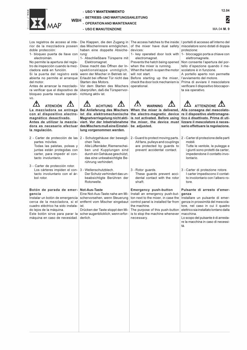
I portelli di accesso all’interno delmiscelatore sono dotati di doppiaprotezione:1- bloccaggio porta a chiave con
elettromagnete.Non consente l’apertura del por-tello d’ispezione quando il me-scolatore è in funzione.A portello aperto non permettel’avviamento del motore.Prima di avviare il mescolatoreverificare il dispositivo bloccapor-ta sia operativo.
ATTENZIONEAlla consegna del mescolato-re il dispositivo elettromagne-tico è disattivato. Prima di uti-lizzare il mescolatore è neces-sario effettuare la regolazione.
2 - Carter di protezione delle partimobili.Tutte le ventole, le pulegge ei giunti sono protetti da carter,impedendone il contatto invo-lontario.
3 - Carter di protezione rotore.I carter impediscono il contat-to involontario con l’albero ro-tore.
Pulsante di arresto d’emer-genzaInstallare un pulsante di emer-genza in prossimità del mescola-tore, nel caso in cui il quadroelettrico sia installato lontano dallamacchina.Lo scopo del pulsante è di arresta-re la macchina in caso di necessi-tà.
The access hatches to the insideof the mixer have dual safetydevices:1- key operated door lock with
electromagnet.Prevents the hatch being openedwhen the mixer is running.When the hatch is open the motorwill not start.Before starting up the mixer,check the door lock mechanism isoperational.
WARNINGWhen the mixer is delivered,the electro-magnetic deviceis not activated. Before usingthe mixer, the device mustbe adjusted.
2 - Guard to protect moving parts.All fans, pulleys and couplingsare protected by guards toprevent accidental contact.
3 - Rotor guards.These guards prevent acci-dental contact with the rotorshaft.
Emergency push-buttonInstall an emergency push-but-ton next to the mixer, in case thecontrol panel is installed far fromthe machine.The purpose of this push-buttonis to stop the machine whenevernecessary.
Die Klappen, die den Zugang indas Mischerinnere ermöglichen,haben eine doppelte Absiche-rung:1- Abschließbare Türsperre mit
Elektromagnet.Diese macht das Öffnen der In-spektionsklappe unmöglich,wenn der Mischer in Betrieb ist.Erlaubt bei offener Tür nicht dasStarten des Motors.Vor dem Starten des Mischersüberprüfen, daß die Türsperrvor-richtung aktiv ist.
ACHTUNGBei Anlieferung des Mischersist die elektromechanischeMagnetverriegelung nicht akti-viert. Vor der Inbetriebnahmedes Mischers muß eine Einstel-lung vorgenommen werden.
2 - Schutzgehäuse der bewegli-chen Teile.Alle Lüfterräder, Riemenschei-ben und Kupplungen sinddurch ein Gehäuse geschützt,das eine unbeabsichtigte Be-rührung verhindert.
3 - Wellenschutzblech.Der Schutz verhindert das un-beabsichtigte Berühren derRotorwelle.
Not-Aus-TasteEine Not-Aus-Taste nahe am Mi-schervorsehen, wenn Steuerungentfernt vom Mischer eingebautist.Drücken der Taste stoppt den Mi-scher augenblicklich, wenn erfor-derlich.
Los registros de acceso al inte-rior de la mezcladora poseendoble protección:1- bloqueo puerta de llave con
electroimán.No permite la apertura del regis-tro de inspección cuando la mez-cladora está en función.Si la puerta del registro estáabierta no permite el arranquedel motor.Antes de arrancar la mezclado-ra verificar que el dispositivo debloqueo puerta resulte operati-vo.
ATENCIÓNLa mezcladora se entregacon el dispositivo electro-magnético desactivado.Antes de utilizar la mezcla-dora es necesario efectuarla regulación.
2 - Carter de protección de laspartes móviles.Todas las paletas, poleas yjuntas están protegidas concarter, para impedir el con-tacto involuntario.
3 - Carter de protección rotor.Los cárteres impiden el con-tacto involuntario con el ár-bol rotor.
Botón de parada de emer-genciaInstalar un botón de emergenciacerca de la mezcladora, si elcuadro eléctrico ha sido instala-do lejos de la máquina.Este botón sirve para parar lamáquina en caso de necesidad.
12.04
2
-
-
-
-
WBH
USO Y MANTENIMIENTO
BETRIEBS- UND WARTUNGSANLEITUNG
OPERATION AND MAINTENANCE
USO E MANUTENZIONE MA.04 M. 10
POSTO DI LAVOROLa macchina non richiede la pre-senza continua dell’operatore.L’operatore, per poter interveni-re in caso di emergenza dovràpremere uno dei pulsanti di arre-sto d’emergenza collocati nelleseguenti posizioni:- sul mescolatore, quando il qua-
dro elettrico di alimentazioneelettrica è molto distante.
- Sul quadro elettrico del mesco-latore (quando previsto).
- Sul quadro elettrico dell’impian-to.
WORK STATIONThe operator does not have to bepresent at all times.To take action in an emergency,the operator must push one ofthe Emergency Stop Buttonswhich must be located in thefollowing positions:- on the mixer if the power supply
control board is fairly distant.- On the control panel of the mix-
er (when designed for this).- On the electric control panel of
the plant.
ARBEITSPLATZDie Maschine braucht nicht stän-dig vom Bediener überwacht zuwerden.Um die Maschine im Notfall zumStillstand zu bringen, muß derBediener eine der Not-Aus-Schlagtasten betätigen, die sichan folgenden Stellen befindenmüssen:- am Mischer, wenn die Schaltta-
fel der Stromversorgung weiterentfernt ist.
- Auf der Schalttafel des Mischers(falls vorgesehen).
- Auf der Schalttafel der Anlage.
PUESTO DE TRABAJOLa máquina no requiere la pre-sencia constante del operador.El operador, para poder interve-nir en caso de emergencia debeapretar uno de los botones deparada de emergencia ubicadosen las siguientes posiciones:- en la mezcladora, cuando el
cuadro eléctrico de alimenta-ción eléctrica está muy distan-te.
- En el cuadro eléctrico de lamezcladora (cuando está pre-sente).
- En el cuadro eléctrico de la ins-talación.
12.04
2
MA.04 M. 11
-
-
-
-
WBH
USO Y MANTENIMIENTO
BETRIEBS- UND WARTUNGSANLEITUNG
OPERATION AND MAINTENANCE
USO E MANUTENZIONE
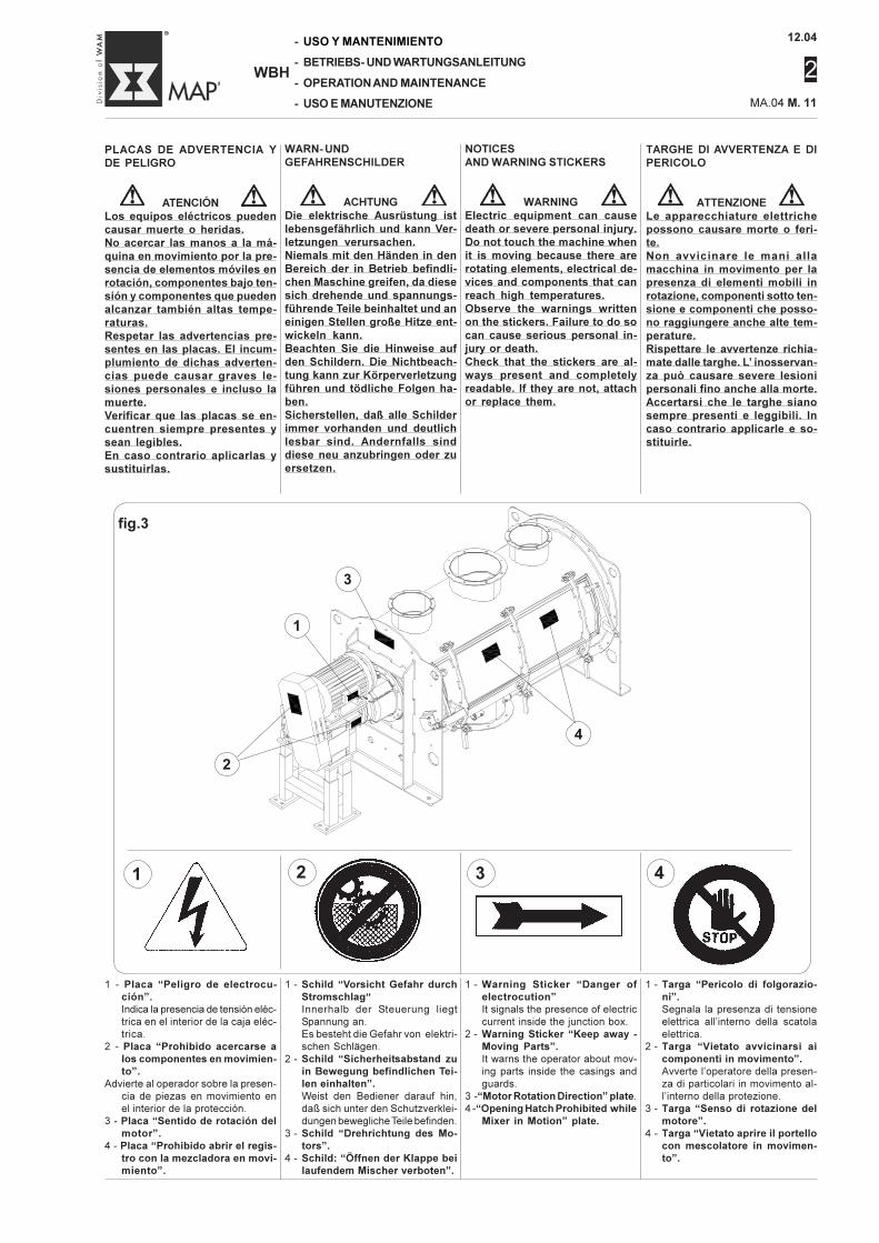
TARGHE DI AVVERTENZA E DIPERICOLO
ATTENZIONELe apparecchiature elettrichepossono causare morte o feri-te.Non avvicinare le mani allamacchina in movimento per lapresenza di elementi mobili inrotazione, componenti sotto ten-sione e componenti che posso-no raggiungere anche alte tem-perature.Rispettare le avvertenze richia-mate dalle targhe. L’ inosservan-za può causare severe lesionipersonali fino anche alla morte.Accertarsi che le targhe sianosempre presenti e leggibili. Incaso contrario applicarle e so-stituirle.
PLACAS DE ADVERTENCIA YDE PELIGRO
ATENCIÓNLos equipos eléctricos puedencausar muerte o heridas.No acercar las manos a la má-quina en movimiento por la pre-sencia de elementos móviles enrotación, componentes bajo ten-sión y componentes que puedenalcanzar también altas tempe-raturas.Respetar las advertencias pre-sentes en las placas. El incum-plumiento de dichas adverten-cias puede causar graves le-siones personales e incluso lamuerte.Verificar que las placas se en-cuentren siempre presentes ysean legibles.En caso contrario aplicarlas ysustituirlas.
WARN- UNDGEFAHRENSCHILDER
ACHTUNGDie elektrische Ausrüstung istlebensgefährlich und kann Ver-letzungen verursachen.Niemals mit den Händen in denBereich der in Betrieb befindli-chen Maschine greifen, da diesesich drehende und spannungs-führende Teile beinhaltet und aneinigen Stellen große Hitze ent-wickeln kann.Beachten Sie die Hinweise aufden Schildern. Die Nichtbeach-tung kann zur Körperverletzungführen und tödliche Folgen ha-ben.Sicherstellen, daß alle Schilderimmer vorhanden und deutlichlesbar sind. Andernfalls sinddiese neu anzubringen oder zuersetzen.
NOTICESAND WARNING STICKERS
WARNINGElectric equipment can causedeath or severe personal injury.Do not touch the machine whenit is moving because there arerotating elements, electrical de-vices and components that canreach high temperatures.Observe the warnings writtenon the stickers. Failure to do socan cause serious personal in-jury or death.Check that the stickers are al-ways present and completelyreadable. If they are not, attachor replace them.
1 - Targa “Pericolo di folgorazio-ni”.Segnala la presenza di tensione
elettrica all’interno della scatola
elettrica.
2 - Targa “Vietato avvicinarsi aicomponenti in movimento”.Avverte l’operatore della presen-
za di particolari in movimento al-
l’interno della protezione.
3 - Targa “Senso di rotazione delmotore”.
4 - Targa “Vietato aprire il portellocon mescolatore in movimen-to”.
1 - Placa “Peligro de electrocu-ción”.Indica la presencia de tensión eléc-
trica en el interior de la caja eléc-
trica.
2 - Placa “Prohibido acercarse alos componentes en movimien-to”.
Advierte al operador sobre la presen-
cia de piezas en movimiento en
el interior de la protección.
3 - Placa “Sentido de rotación delmotor”.
4 - Placa “Prohibido abrir el regis-tro con la mezcladora en movi-miento”.
1 - Schild “Vorsicht Gefahr durchStromschlag“Innerhalb der Steuerung liegt
Spannung an.
Es besteht die Gefahr von elektri-
schen Schlägen.
2 - Schild “Sicherheitsabstand zuin Bewegung befindlichen Tei-len einhalten”.Weist den Bediener darauf hin,
daß sich unter den Schutzverklei-
dungen bewegliche Teile befinden.
3 - Schild “Drehrichtung des Mo-tors”.
4 - Schild: “Öffnen der Klappe beilaufendem Mischer verboten”.
1 - Warning Sticker “Danger ofelectrocution”It signals the presence of electric
current inside the junction box.
2 - Warning Sticker “Keep away -Moving Parts”.It warns the operator about mov-
ing parts inside the casings and
guards.
3 -“Motor Rotation Direction” plate.
4 -“Opening Hatch Prohibited whileMixer in Motion” plate.
1 2 3 4
fig.3
1
•
2
•
3
•
4
•
12.04
2
-
-
-
-
WBH
USO Y MANTENIMIENTO
BETRIEBS- UND WARTUNGSANLEITUNG
OPERATION AND MAINTENANCE
USO E MANUTENZIONE MA.04 M. 12
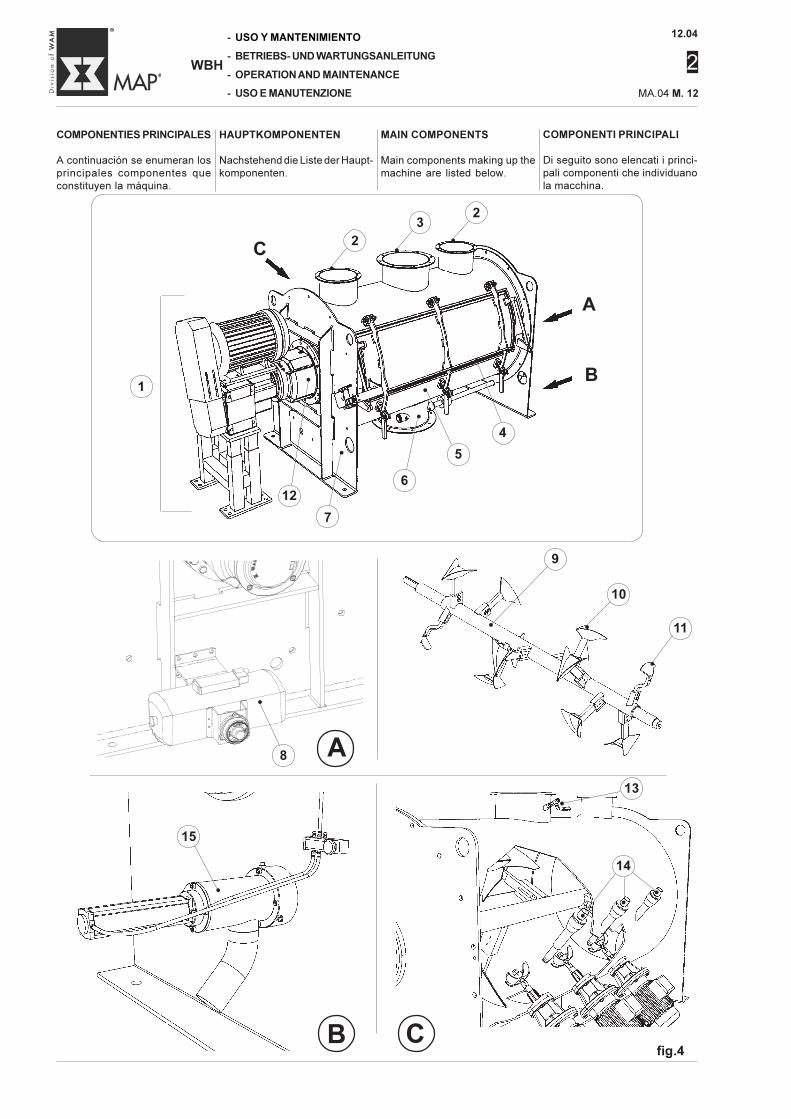
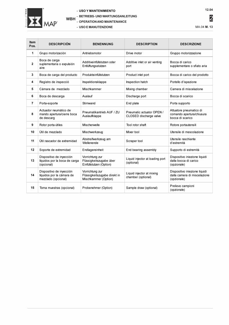
COMPONENTI PRINCIPALI
Di seguito sono elencati i princi-pali componenti che individuanola macchina.
COMPONENTIES PRINCIPALES
A continuación se enumeran losprincipales componentes queconstituyen la máquina.
HAUPTKOMPONENTEN
Nachstehend die Liste der Haupt-komponenten.
MAIN COMPONENTS
Main components making up themachine are listed below.
A
B Cfig.4
C
A
B
2
•
2
•
3
•
12
•
7
•
6
•
5
•
4
•
1
8
•
15
•
13•
14
••
•
9
•
10
• 11
•
12.04
2
MA.04 M. 13
-
-
-
-
WBH
USO Y MANTENIMIENTO
BETRIEBS- UND WARTUNGSANLEITUNG
OPERATION AND MAINTENANCE
USO E MANUTENZIONE
Item
Pos.DESCRIPCIÓN BENENNUNG DESCRIPTION DESCRIZIONE
1 Grupo motorización Antriebsmotor Drive motor Gruppo motorizzazione
2Boca de cargasuplementaria o expulsiónaire
Additiveinfüllstutzen oderEntlüftungsstutzen
Additive inlet or air ventingport
Bocca di caricosupplementare o sfiato aria
3 Boca de carga del producto Produkteinfüllstutzen Product inlet port Bocca di carico del prodotto
4 Registro de inspecció Inspektionsklappe Inspection hatch Portello d’ispezione
5 Cámara de mezclado Mischkammer Mixing chamber Camera di miscelazione
6 Boca de descarga Auslauf Discharge port Bocca di scarico
7 Porta-soporte Stirnwand End plate Porta supporto
8Actuador neumático demando apertura/cierre bocade descarg
Pneumatikantrieb AUF / ZUAuslaufklappe
Pneumatic actuator OPEN /CLOSED discharge valve
Attuatore pneumatico dicomando apertura/chiusurabocca di scarico
9 Rotor porta-útiles Mischerwelle Tool rotor shaft Rotore portautensili
10 Útil de mezclado Mischwerkzeug Mixer tool Utensile di mescolazione
11 Útil rascador de extremidadAbstreifwerkzeug amWellenende
Scraper toolUtensile raschianted’estremità
12 Soporte de extremidad Endlagereinheit End bearing assembly Supporto di estremità
13Dispositivo de inyecciónlíquidos por la boca de carga(opcional)
Vorrichtung zurFlüssigkeitszugabe überEinfüllstutzen (Option)
Liquid injector at loading port(optional)
Dispositivo iniezione liquididalla bocca di carico(opzionale)
14Dispositivo de inyecciónlíquidos por la cámara demezclado (opcional)
Vorrichtung zurFlüssigkeitszugabe direkt inMischkammer (Option)
Liquid injector at mixingchamber (optional)
Dispositivo iniezione liquididalla camera di miscelazione(opzionale)
15 Toma muestras (opcional) Probenehmer (Option) Sample draw (optional)Prelievo campioni(opzionale)
12.04
2
-
-
-
-
WBH
USO Y MANTENIMIENTO
BETRIEBS- UND WARTUNGSANLEITUNG
OPERATION AND MAINTENANCE
USO E MANUTENZIONE MA.04 M. 14
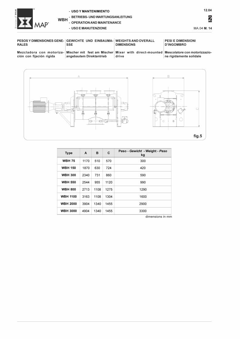
PESOS Y DIMENSIONES GENE-RALES
Mezcladora con motoriza-ción con fijación rígida
GEWICHTE UND EINBAUMA-SSE
Mischer mit fest am Mischerangebautem Direktantrieb
WEIGHTS AND OVERALLDIMENSIONS
Mixer with direct-mounteddrive
PESI E DIMENSIONID’INGOMBRO
Mescolatore con motorizzazio-ne rigidamente solidale
fig.5
dimensions in mm
Type A B CPeso - Gewicht - Weight - Peso
kg
WBH 75 1170 510 570 300
WBH 150 1870 630 724 420
WBH 300 2340 731 860 590
WBH 550 2544 955 1120 990
WBH 800 2713 1108 1275 1290
WBH 1100 3163 1108 1304 1600
WBH 2000 3904 1340 1455 2900
WBH 3000 4904 1340 1455 3300
12.04
2
MA.04 M. 15
-
-
-
-
WBH
USO Y MANTENIMIENTO
BETRIEBS- UND WARTUNGSANLEITUNG
OPERATION AND MAINTENANCE
USO E MANUTENZIONE
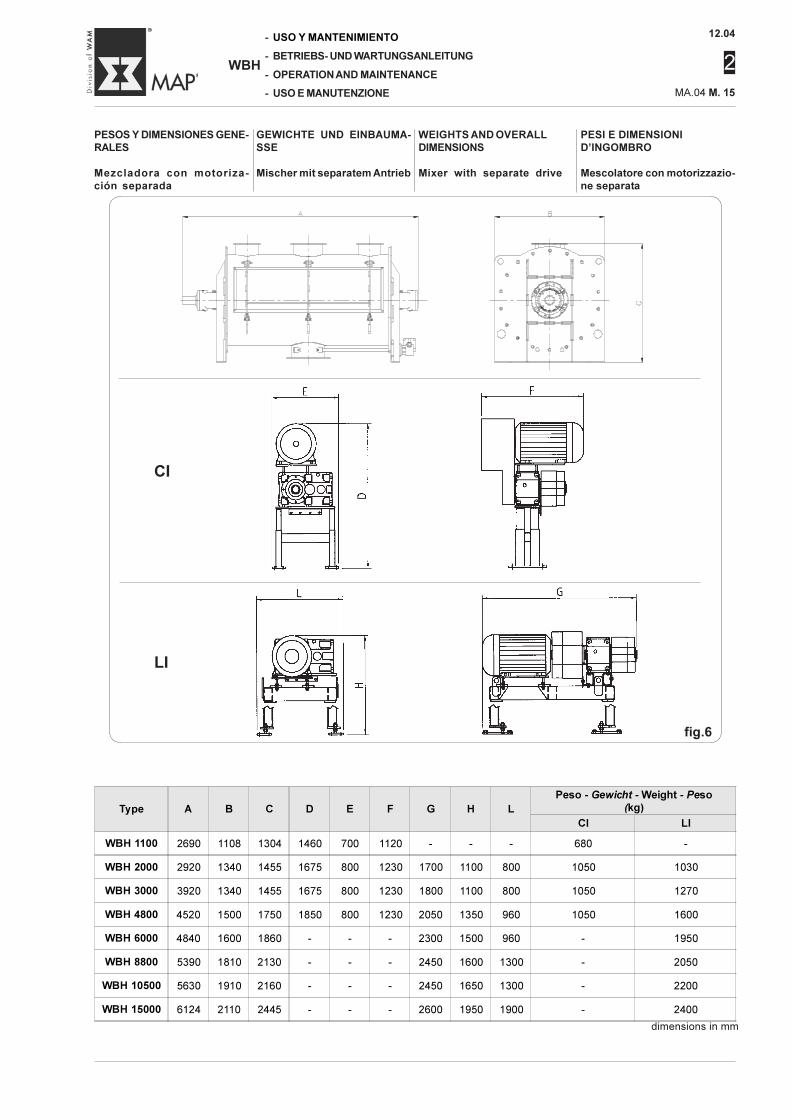
PESOS Y DIMENSIONES GENE-RALES
Mezcladora con motoriza-ción separada
GEWICHTE UND EINBAUMA-SSE
Mischer mit separatem Antrieb
WEIGHTS AND OVERALLDIMENSIONS
Mixer with separate drive
PESI E DIMENSIONID’INGOMBRO
Mescolatore con motorizzazio-ne separata
CI
LI
fig.6
Type A B C D E F G H L
Peso - Gewicht - Weight - Peso
(kg)
CI LI
WBH 1100 2690 1108 1304 1460 700 1120 - - - 680 -
WBH 2000 2920 1340 1455 1675 800 1230 1700 1100 800 1050 1030
WBH 3000 3920 1340 1455 1675 800 1230 1800 1100 800 1050 1270
WBH 4800 4520 1500 1750 1850 800 1230 2050 1350 960 1050 1600
WBH 6000 4840 1600 1860 - - - 2300 1500 960 - 1950
WBH 8800 5390 1810 2130 - - - 2450 1600 1300 - 2050
WBH 10500 5630 1910 2160 - - - 2450 1650 1300 - 2200
WBH 15000 6124 2110 2445 - - - 2600 1950 1900 - 2400
dimensions in mm
12.04
2
-
-
-
-
WBH
USO Y MANTENIMIENTO
BETRIEBS- UND WARTUNGSANLEITUNG
OPERATION AND MAINTENANCE
USO E MANUTENZIONE MA.04 M. 16
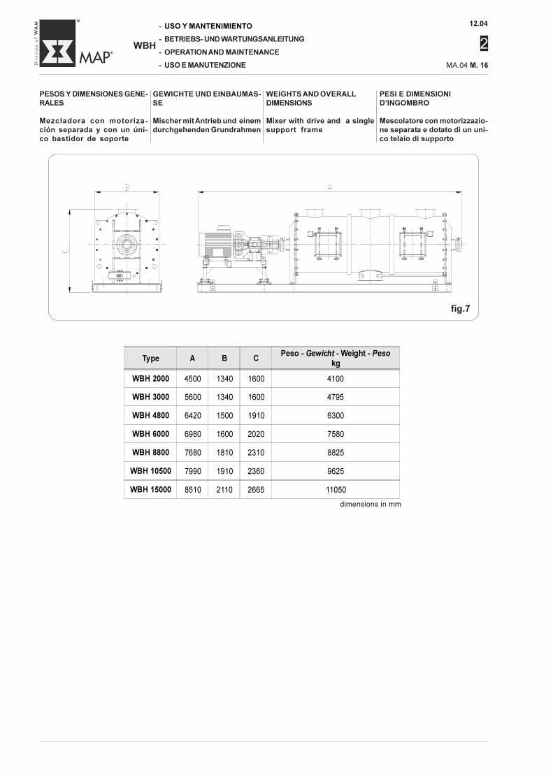
PESOS Y DIMENSIONES GENE-RALES
Mezcladora con motoriza-ción separada y con un úni-co bastidor de soporte
GEWICHTE UND EINBAUMAS-SE
Mischer mit Antrieb und einemdurchgehenden Grundrahmen
WEIGHTS AND OVERALLDIMENSIONS
Mixer with drive and a singlesupport frame
PESI E DIMENSIONID’INGOMBRO
Mescolatore con motorizzazio-ne separata e dotato di un uni-co telaio di supporto
fig.7
Type A B CPeso - Gewicht - Weight - Peso
kg
WBH 2000 4500 1340 1600 4100
WBH 3000 5600 1340 1600 4795
WBH 4800 6420 1500 1910 6300
WBH 6000 6980 1600 2020 7580
WBH 8800 7680 1810 2310 8825
WBH 10500 7990 1910 2360 9625
WBH 15000 8510 2110 2665 11050
dimensions in mm
12.04
2
MA.04 M. 17
-
-
-
-
WBH
USO Y MANTENIMIENTO
BETRIEBS- UND WARTUNGSANLEITUNG
OPERATION AND MAINTENANCE
USO E MANUTENZIONE
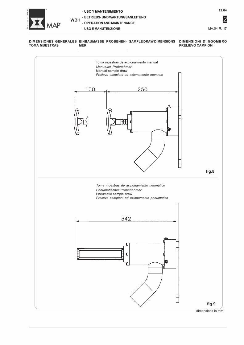
Toma muestras de accionamiento manual
Manueller Probnehmer
Manual sample drawPrelievo campioni ad azionamento manuale
Toma muestras de accionamiento neumático
Pneumatischer Probenehmer
Pneumatic sample drawPrelievo campioni ad azionamento pneumatico
DIMENSIONES GENERALESTOMA MUESTRAS
EINBAUMASSE PROBENEH-MER
SAMPLE DRAW DIMENSIONS DIMENSIONI D’INGOMBROPRELIEVO CAMPIONI
fig.8
fig.9
dimensions in mm
12.04
2
-
-
-
-
WBH
USO Y MANTENIMIENTO
BETRIEBS- UND WARTUNGSANLEITUNG
OPERATION AND MAINTENANCE
USO E MANUTENZIONE MA.04 M. 18
RUMOROSITÀ
Il livello di pressione acustica avuoto è inferiore a ≤ 83 dB(A).Il livello di pressione acustica inlavoro dipende dalla natura delmateriale da mescolare.Il datore di lavoro dovrà attuare,nell'ambiente di lavoro, le misu-re tecniche adeguate per ridurreal minimo i rischi derivanti dal-l'esposizione giornaliera al rumo-re.
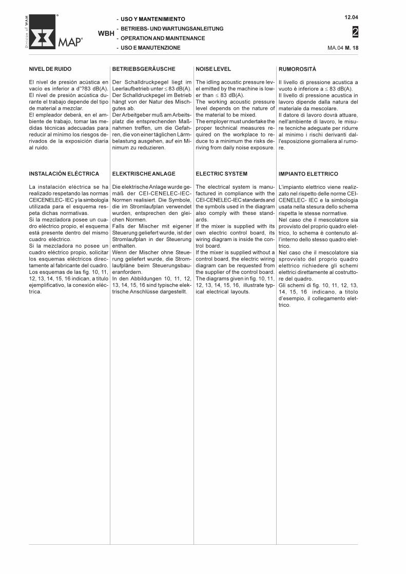
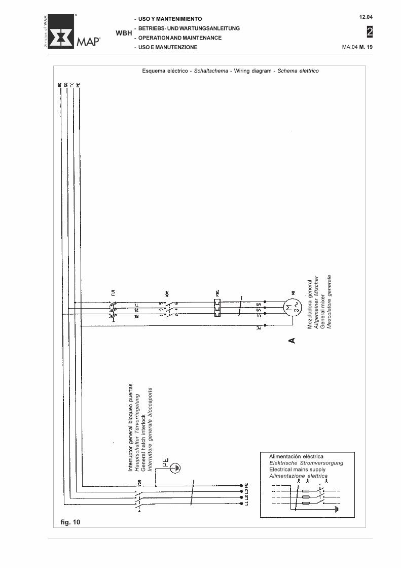
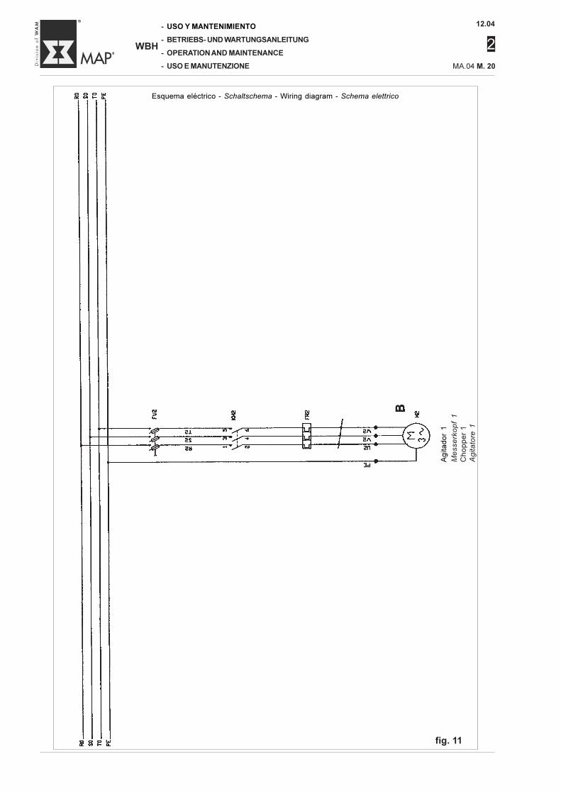
IMPIANTO ELETTRICO
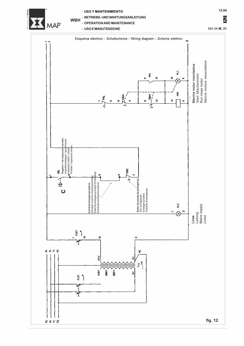
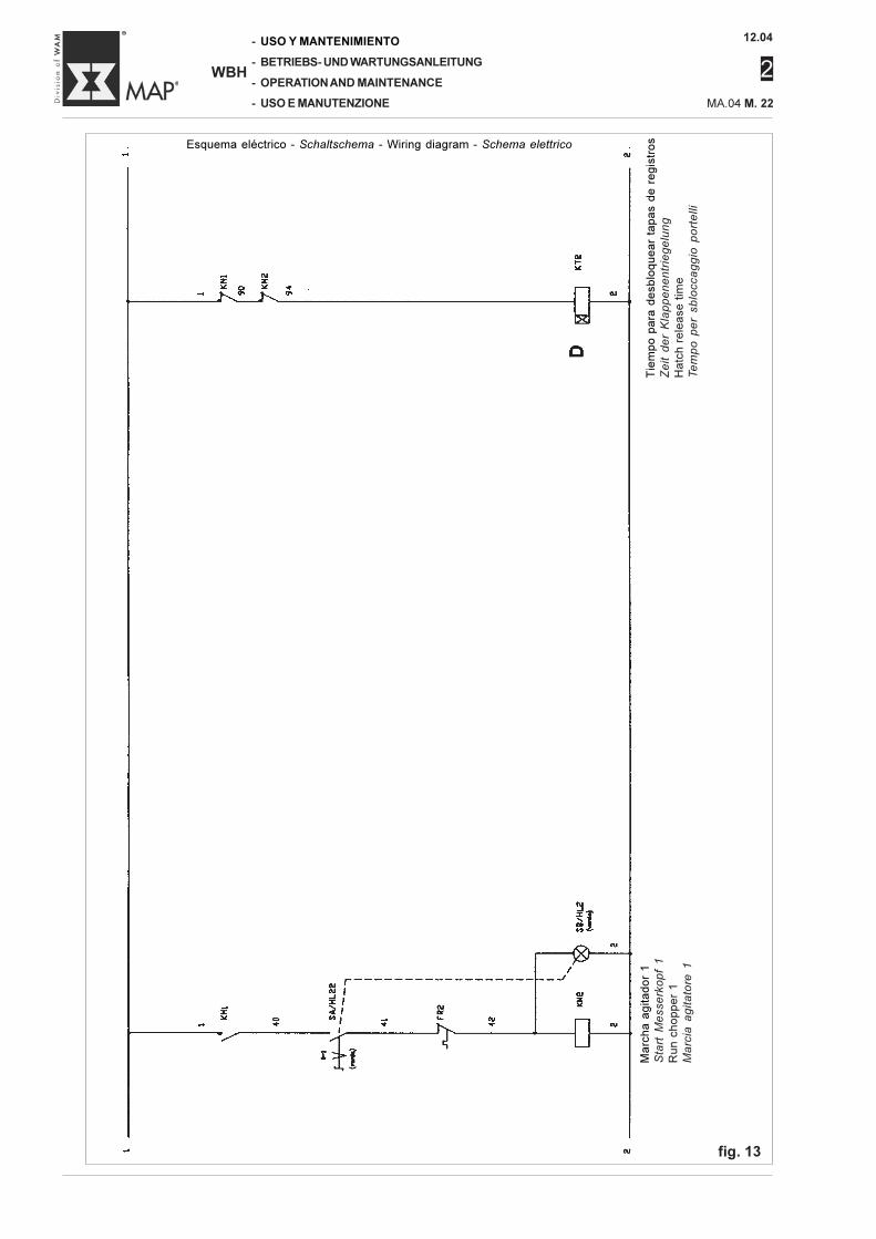
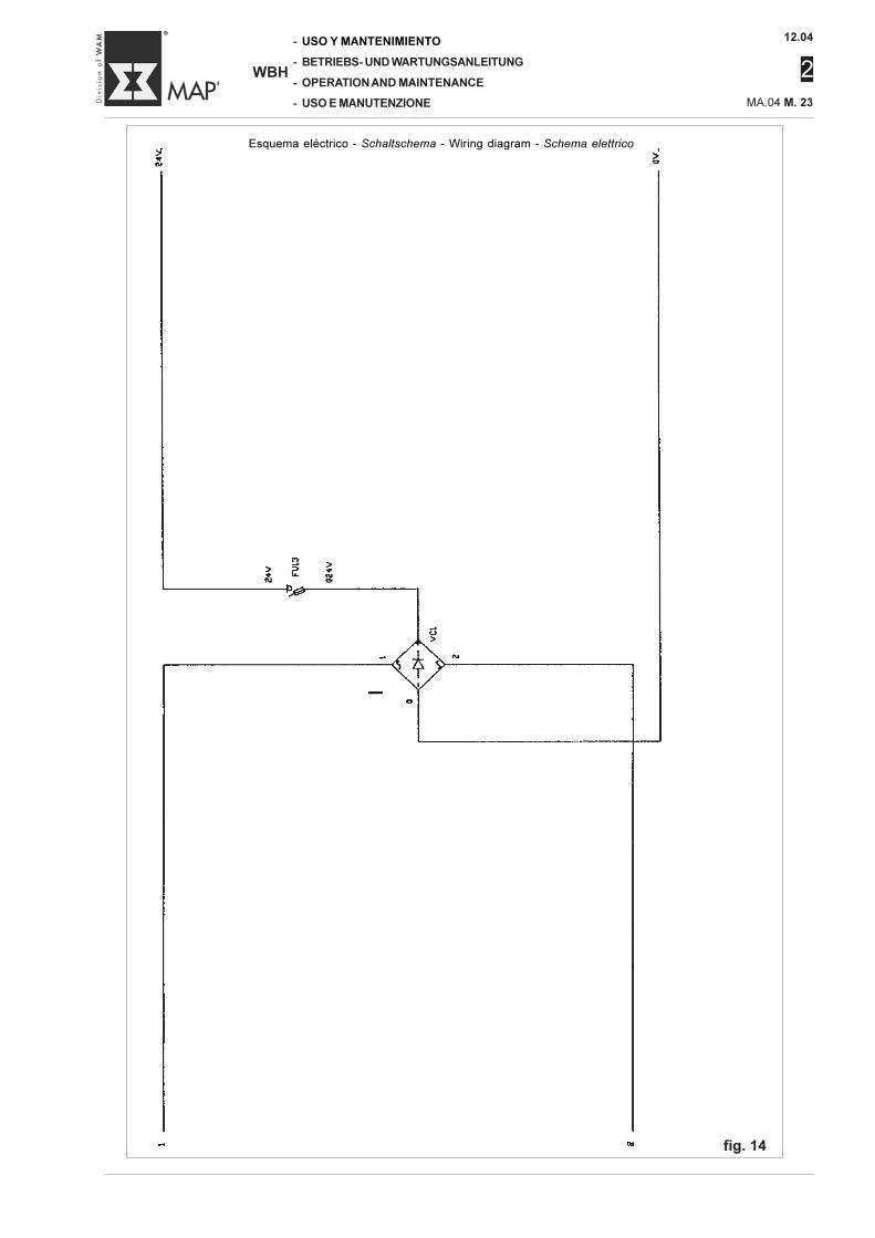
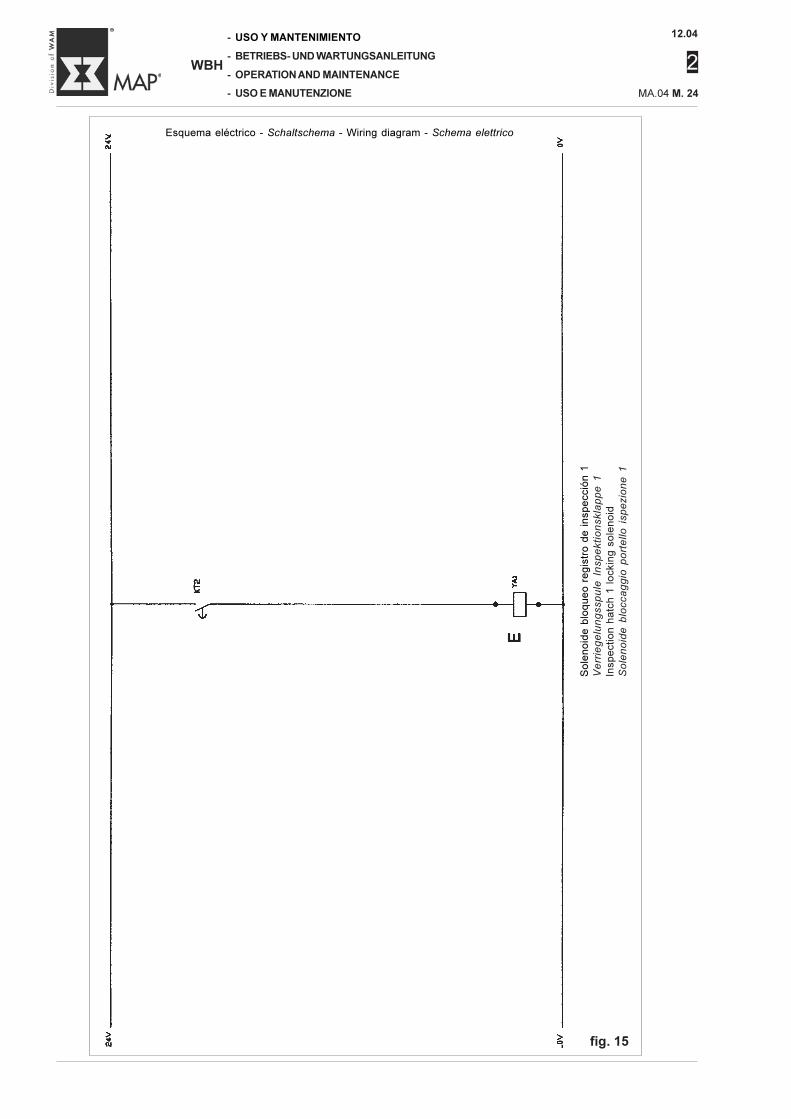
L’impianto elettrico viene realiz-zato nel rispetto delle norme CEI-CENELEC- IEC e la simbologiausata nella stesura dello schemarispetta le stesse normative.Nel caso che il mescolatore siaprovvisto del proprio quadro elet-trico, lo schema è contenuto al-l’interno dello stesso quadro elet-trico.Nel caso che il mescolatore siasprovvisto del proprio quadroelettrico richiedere gli schemielettrici direttamente al costrutto-re del quadro.Gli schemi di fig. 10, 11, 12, 13,14, 15, 16 indicano, a titolod’esempio, il collegamento elet-trico.
NIVEL DE RUIDO
El nivel de presión acústica envacío es inferior a d”?83 dB(A).El nivel de presión acústica du-rante el trabajo depende del tipode material a mezclar.El empleador deberá, en el am-biente de trabajo, tomar las me-didas técnicas adecuadas parareducir al mínimo los riesgos de-rivados de la exposición diariaal ruido.
INSTALACIÓN ELÉCTRICA
La instalación eléctrica se harealizado respetando las normasCEICENELEC- IEC y la simbologíautilizada para el esquema res-peta dichas normativas.Si la mezcladora posee un cua-dro eléctrico propio, el esquemaestá presente dentro del mismocuadro eléctrico.Si la mezcladora no posee uncuadro eléctrico propio, solicitarlos esquemas eléctricos direc-tamente al fabricante del cuadro.Los esquemas de las fig. 10, 11,12, 13, 14, 15, 16 indican, a títuloejemplificativo, la conexión eléc-trica.
BETRIEBSGERÄUSCHE
Der Schalldruckpegel liegt imLeerlaufbetrieb unter ≤ 83 dB(A).Der Schalldruckpegel im Betriebhängt von der Natur des Misch-gutes ab.Der Arbeitgeber muß am Arbeits-platz die entsprechenden Maß-nahmen treffen, um die Gefah-ren, die von einer täglichen Lärm-belastung ausgehen, auf ein Mi-nimum zu reduzieren.
ELEKTRISCHE ANLAGE
Die elektrische Anlage wurde ge-mäß der CEI-CENELEC-IEC-Normen realisiert. Die Symbole,die im Stromlaufplan verwendetwurden, entsprechen den glei-chen Normen.Falls der Mischer mit eigenerSteuerung geliefert wurde, ist derStromlaufplan in der Steuerungenthalten.Wenn der Mischer ohne Steue-rung geliefert wurde, die Strom-laufpläne beim Steuerungsbau-eranfordern.In den Abbildungen 10, 11, 12,13, 14, 15, 16 sind typische elek-trische Anschlüsse dargestellt.
NOISE LEVEL
The idling acoustic pressure lev-el emitted by the machine is low-er than ≤ 83 dB(A).The working acoustic pressurelevel depends on the nature ofthe material to be mixed.The employer must undertake theproper technical measures re-quired on the workplace to re-duce to a minimum the risks de-riving from daily noise exposure.
ELECTRIC SYSTEM
The electrical system is manu-factured in compliance with theCEI-CENELEC-IEC standards andthe symbols used in the diagramalso comply with these stand-ards.If the mixer is supplied with itsown electric control board, itswiring diagram is inside the con-trol board.If the mixer is supplied without acontrol board, the electric wiringdiagram can be requested fromthe supplier of the control board.The diagrams given in fig. 10, 11,12, 13, 14, 15, 16, illustrate typ-ical electrical layouts.
12.04
2
MA.04 M. 19
-
-
-
-
WBH
USO Y MANTENIMIENTO
BETRIEBS- UND WARTUNGSANLEITUNG
OPERATION AND MAINTENANCE
USO E MANUTENZIONE
Alimentación eléctricaElektrische Stromversorgung
Electrical mains supplyAlimentazione elettrica
Inte
rru
pto
r g
en
era
l b
loq
ue
o p
ue
rta
sH
au
pts
ch
alt
er
Tü
rve
rrie
ge
lun
g
Ge
ne
ral
ha
tch
in
terl
ock
Inte
rru
tto
re g
en
era
le b
locca
po
rta
Me
zcla
do
ra g
en
era
lA
llg
em
ein
er
Mis
ch
er
Ge
ne
ral m
ixe
rM
esco
lato
re g
en
era
le
fig. 10
Esquema eléctrico - Schaltschema - Wiring diagram - Schema elettrico
12.04
2
-
-
-
-
WBH
USO Y MANTENIMIENTO
BETRIEBS- UND WARTUNGSANLEITUNG
OPERATION AND MAINTENANCE
USO E MANUTENZIONE MA.04 M. 20
Ag
itad
or
1
Me
sse
rko
pf
1
Ch
op
pe
r 1
Ag
ita
tore
1
fig. 11
Esquema eléctrico - Schaltschema - Wiring diagram - Schema elettrico
12.04
2
MA.04 M. 21
-
-
-
-
WBH
USO Y MANTENIMIENTO
BETRIEBS- UND WARTUNGSANLEITUNG
OPERATION AND MAINTENANCE
USO E MANUTENZIONE
Ma
rch
a m
oto
r m
ezc
lad
ora
Sta
rt M
isch
erm
oto
r
Ru
n m
ixe
r m
oto
rM
arc
ia m
oto
re m
esco
lato
re
Líne
aL
eit
un
g
Ma
ins
sup
ply
Lin
ea
Botó
n d
e p
ara
da d
e e
merg
encia
Pilz
-Sch
lagta
ste
Em
erg
ency
button
Puls
ante
di e
merg
enza
•
Eve
ntu
al e
merg
encia
ext
ern
a
Etw
aig
er ext
ern
er N
ots
toppsc
halte
rE
xte
rnal e
merg
ency b
utton (if in
sta
lled)
Eve
ntu
ale
em
erg
enza
est
ern
a •
Re
gis
tro
1 d
e in
sp
ecció
n c
err
ad
o
Insp
ekt
ionsk
lappe 1
gesc
hlo
ssen
Inspection h
atc
h 1
clo
sed
Port
ello
1 is
pezi
one c
hiu
so
fig. 12
Esquema eléctrico - Schaltschema - Wiring diagram - Schema elettrico
12.04
2
-
-
-
-
WBH
USO Y MANTENIMIENTO
BETRIEBS- UND WARTUNGSANLEITUNG
OPERATION AND MAINTENANCE
USO E MANUTENZIONE MA.04 M. 22
Ma
rch
a a
gita
do
r 1
Sta
rt M
esse
rko
pf
1
Ru
n c
ho
pp
er
1M
arc
ia a
gita
tore
1
Tie
mp
o p
ara
de
sblo
qu
ea
r ta
pa
s d
e r
eg
istr
os
Ze
it d
er
Kla
pp
en
en
trie
ge
lun
g
Ha
tch
re
lea
se t
ime
Te
mp
o p
er
sb
locca
gg
io p
ort
elli
fig. 13
Esquema eléctrico - Schaltschema - Wiring diagram - Schema elettrico
12.04
2
MA.04 M. 23
-
-
-
-
WBH
USO Y MANTENIMIENTO
BETRIEBS- UND WARTUNGSANLEITUNG
OPERATION AND MAINTENANCE
USO E MANUTENZIONE
fig. 14
Esquema eléctrico - Schaltschema - Wiring diagram - Schema elettrico
12.04
2
-
-
-
-
WBH
USO Y MANTENIMIENTO
BETRIEBS- UND WARTUNGSANLEITUNG
OPERATION AND MAINTENANCE
USO E MANUTENZIONE MA.04 M. 24
So
len
oid
e b
loq
ue
o r
eg
istr
o d
e i
nsp
ecc
ión
1V
err
ieg
elu
ng
ssp
ule
In
sp
ekti
on
skla
pp
e 1
Insp
ect
ion
ha
tch
1 l
ock
ing
so
len
oid
So
len
oid
e b
locca
gg
io p
ort
ello
isp
ezio
ne
1
fig. 15
Esquema eléctrico - Schaltschema - Wiring diagram - Schema elettrico
12.04
2
MA.04 M. 25
-
-
-
-
WBH
USO Y MANTENIMIENTO
BETRIEBS- UND WARTUNGSANLEITUNG
OPERATION AND MAINTENANCE
USO E MANUTENZIONE
Ele
ctr
oválv
ula
cie
rre/a
pert
ura
boca d
e d
escarg
a s
ecundaria
Magnetv
entil
für S
chlie
ßen/Ö
ffnen d
es
zusä
tzlic
hen A
usl
aufs
Additio
nal d
ischarg
e p
ort
open/c
lose s
ole
noid
Ele
ttro
valv
ola
chiu
sura
/apert
ura
bocc
a d
i sca
rico
seco
ndaria
Boca d
e d
escarg
a c
err
ada
Ausl
aufk
lappe g
esc
hlo
ssen
Dis
ch
arg
e p
ort
clo
se
d
Bo
cca
di s
carico
ch
iusa
Boca d
e d
escarg
a a
bie
rta
Ausl
aufk
lappe g
eöffn
et
Dis
ch
arg
e p
ort
clo
se
d
Bo
cca
di s
carico
ap
ert
a
Botó
n c
ierr
e b
oca d
e d
escarg
a
Dru
cksc
ha
lter "A
usl
au
fkla
pp
e s
chlie
ße
n"
Dis
charg
e p
ort
clo
se b
utton
Puls
ante
chiu
sura
bocc
a d
i sca
rico
Botó
n d
e a
pert
ura
boca d
e d
escarg
a
Dru
cksc
halte
r "A
usl
aufk
lappe ö
ffnen"
Dis
charg
e p
ort
open b
utton
Puls
ante
apert
ura
bocc
a d
i sca
rico
Regis
tros d
e in
specció
n c
err
ados
Insp
ekt
ionsk
lappen g
esc
hlo
ssen
Inspection h
atc
hes c
losed
Po
rte
lli is
pe
zio
ne
ch
iusi
Sensor boca d
e d
escarg
a c
err
ada
Senso
r Ausl
aufs
tutz
en g
esc
hlo
ssen
Dis
ch
arg
e p
ort
clo
se
d s
en
so
r
Se
nso
re b
occ
a d
i sca
rico
ch
iusa
Sensor boca d
e d
escarg
a a
bie
rta
Senso
r Ausl
aufs
tutz
en g
eöffn
et
Dis
ch
arg
e p
ort
op
en
se
nso
r
Senso
re b
occ
a d
i sca
rico
apert
a
fig. 16
Esquema eléctrico - Schaltschema - Wiring diagram - Schema elettrico
12.04
2
-
-
-
-
WBH
USO Y MANTENIMIENTO
BETRIEBS- UND WARTUNGSANLEITUNG
OPERATION AND MAINTENANCE
USO E MANUTENZIONE MA.04 M. 26
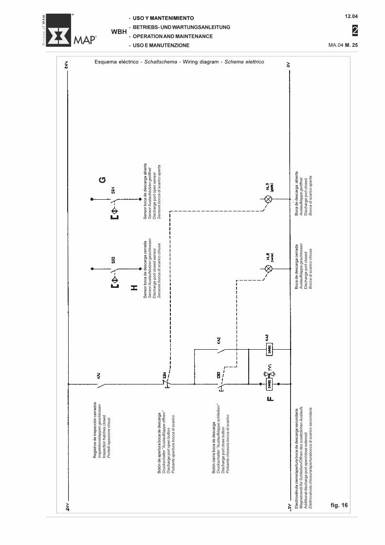
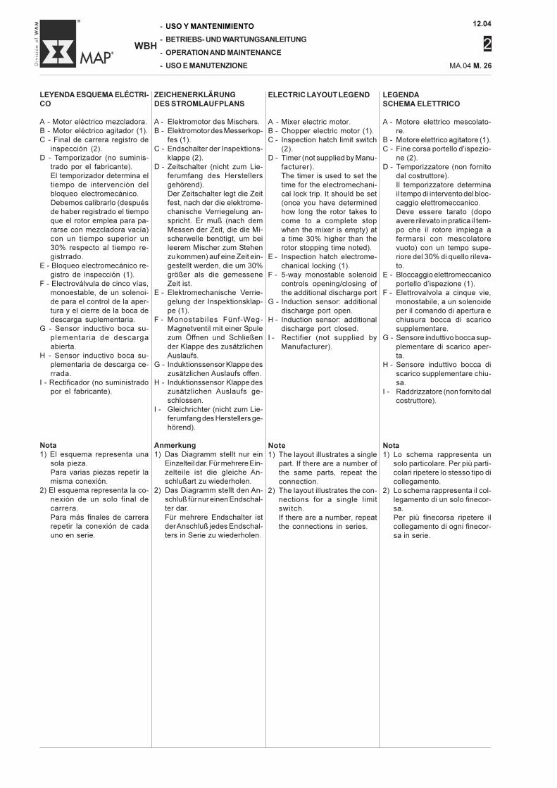
ELECTRIC LAYOUT LEGEND
A - Mixer electric motor.B - Chopper electric motor (1).C - Inspection hatch limit switch
(2).D - Timer (not supplied by Manu-
facturer).The timer is used to set thetime for the electromechani-cal lock trip. It should be set(once you have determinedhow long the rotor takes tocome to a complete stopwhen the mixer is empty) ata time 30% higher than therotor stopping time noted).
E - Inspection hatch electrome-chanical locking (1).
F - 5-way monostable solenoidcontrols opening/closing ofthe additional discharge port
G - Induction sensor: additionaldischarge port open.
H - Induction sensor: additionaldischarge port closed.
I - Rectifier (not supplied byManufacturer).
Note1) The layout illustrates a single
part. If there are a number ofthe same parts, repeat theconnection.
2) The layout illustrates the con-nections for a single limitswitch.If there are a number, repeatthe connections in series.
LEGENDASCHEMA ELETTRICO
A - Motore elettrico mescolato-re.
B - Motore elettrico agitatore (1).C - Fine corsa portello d’ispezio-
ne (2).D - Temporizzatore (non fornito
dal costruttore).Il temporizzatore determinail tempo di intervento del bloc-caggio elettromeccanico.Deve essere tarato (dopoavere rilevato in pratica il tem-po che il rotore impiega afermarsi con mescolatorevuoto) con un tempo supe-riore del 30% di quello rileva-to.
E - Bloccaggio elettromeccanicoportello d’ispezione (1).
F - Elettrovalvola a cinque vie,monostabile, a un solenoideper il comando di apertura echiusura bocca di scaricosupplementare.
G - Sensore induttivo bocca sup-plementare di scarico aper-ta.
H - Sensore induttivo bocca discarico supplementare chiu-sa.
I - Raddrizzatore (non fornito dalcostruttore).
Nota1) Lo schema rappresenta un
solo particolare. Per più parti-colari ripetere lo stesso tipo dicollegamento.
2) Lo schema rappresenta il col-legamento di un solo finecor-sa.Per più finecorsa ripetere ilcollegamento di ogni finecor-sa in serie.
LEYENDA ESQUEMA ELÉCTRI-CO
A - Motor eléctrico mezcladora.B - Motor eléctrico agitador (1).C - Final de carrera registro de
inspección (2).D - Temporizador (no suminis-
trado por el fabricante).El temporizador determina eltiempo de intervención delbloqueo electromecánico.Debemos calibrarlo (despuésde haber registrado el tiempoque el rotor emplea para pa-rarse con mezcladora vacía)con un tiempo superior un30% respecto al tiempo re-gistrrado.
E - Bloqueo electromecánico re-gistro de inspección (1).
F - Electroválvula de cinco vías,monoestable, de un solenoi-de para el control de la aper-tura y el cierre de la boca dedescarga suplementaria.
G - Sensor inductivo boca su-plementaria de descargaabierta.
H - Sensor inductivo boca su-plementaria de descarga ce-rrada.
I - Rectificador (no suministradopor el fabricante).
Nota1) El esquema representa una
sola pieza.Para varias piezas repetir lamisma conexión.
2) El esquema representa la co-nexión de un solo final decarrera.Para más finales de carrerarepetir la conexión de cadauno en serie.
ZEICHENERKLÄRUNGDES STROMLAUFPLANS
A - Elektromotor des Mischers.B - Elektromotor des Messerkop-
fes (1).C - Endschalter der Inspektions-
klappe (2).D - Zeitschalter (nicht zum Lie-
ferumfang des Herstellersgehörend).Der Zeitschalter legt die Zeitfest, nach der die elektrome-chanische Verriegelung an-spricht. Er muß (nach demMessen der Zeit, die die Mi-scherwelle benötigt, um beileerem Mischer zum Stehenzu kommen) auf eine Zeit ein-gestellt werden, die um 30%größer als die gemesseneZeit ist.
E - Elektromechanische Verrie-gelung der Inspektionsklap-pe (1).
F - Monostabiles Fünf-Weg-Magnetventil mit einer Spulezum Öffnen und Schließender Klappe des zusätzlichenAuslaufs.
G - Induktionssensor Klappe deszusätzlichen Auslaufs offen.
H - Induktionssensor Klappe deszusätzlichen Auslaufs ge-schlossen.
I - Gleichrichter (nicht zum Lie-ferumfang des Herstellers ge-hörend).
Anmerkung1) Das Diagramm stellt nur ein
Einzelteil dar. Für mehrere Ein-zelteile ist die gleiche An-schlußart zu wiederholen.
2) Das Diagramm stellt den An-schluß für nur einen Endschal-ter dar.Für mehrere Endschalter istder Anschluß jedes Endschal-ters in Serie zu wiederholen.
12.04
2
MA.04 M. 27
-
-
-
-
WBH
USO Y MANTENIMIENTO
BETRIEBS- UND WARTUNGSANLEITUNG
OPERATION AND MAINTENANCE
USO E MANUTENZIONE
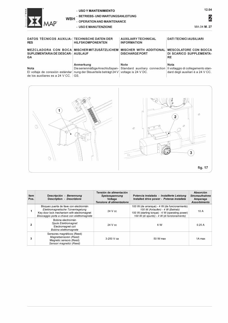
DATI TECNICI AUSILIARI
MESCOLATORE CON BOCCADI SCARICO SUPPLEMENTA-RE
NotaIl voltaggio di collegamento stan-dard degli ausiliari è a 24 V CC.
DATOS TÉCNICOS AUXILIA-RES
MEZCLADORA CON BOCASUPLEMENTARIA DE DESCAR-GA
NotaEl voltaje de conexión estándarde los auxiliares es a 24 V CC.
AUXILIARY TECHNICALINFORMATION
MISCHER WITH ADDITIONALDISCHARGE PORT
NoteStandard auxiliary connectionvoltage is 24 V DC.
TECHNISCHE DATEN DERHILFSKOMPONENTEN
MISCHER MIT ZUSÄTZLICHEMAUSLAUF
AnmerkungDie serienmäßige Anschlußspan-nung der Steuerteile beträgt 24 VGS.
fig. 17
Item
Pos.
Descripción - Benennung
Description - Descrizione
Tensión de alimentación
Speisespannung
Voltage
Tensione di alimentazione
Potencia instalada - Installierte Leistung
Installed drive power - Potenza installata
Absorción
Stromaufnahme
Amperage
Assorbimento
1
Bloqueo puerta de llave con electroimán
Elektromagnetische Türverriegelung
Key door lock mechanism with electromagnet
Bloccaggio porta a chiave con elettromagnete
24 V cc
100 W (de arranque) - 4 W (de funcionamiento)
100 W (Anlaufen) - 4 W (Betrieb)
100 W (starting torque) - 4 W (operating power)
100 W (di spunto) - 4 W (di funzionamento)
10 A
2
Bobina electroimán
Spule Elektromagnet
Electromagnet coil
Bobina elettromagnete
24 V cc 6 W 0.25 A
3
Sensores magnéticos (Reed)
Magnetsensoren (Reed)
Magnetic sensors (Reed)
Sensori magnetici (Reed)
3-250 V ca 50 W max 1A max
1
•
2
•
3•
12.04
2
-
-
-
-
WBH
USO Y MANTENIMIENTO
BETRIEBS- UND WARTUNGSANLEITUNG
OPERATION AND MAINTENANCE
USO E MANUTENZIONE MA.04 M. 28
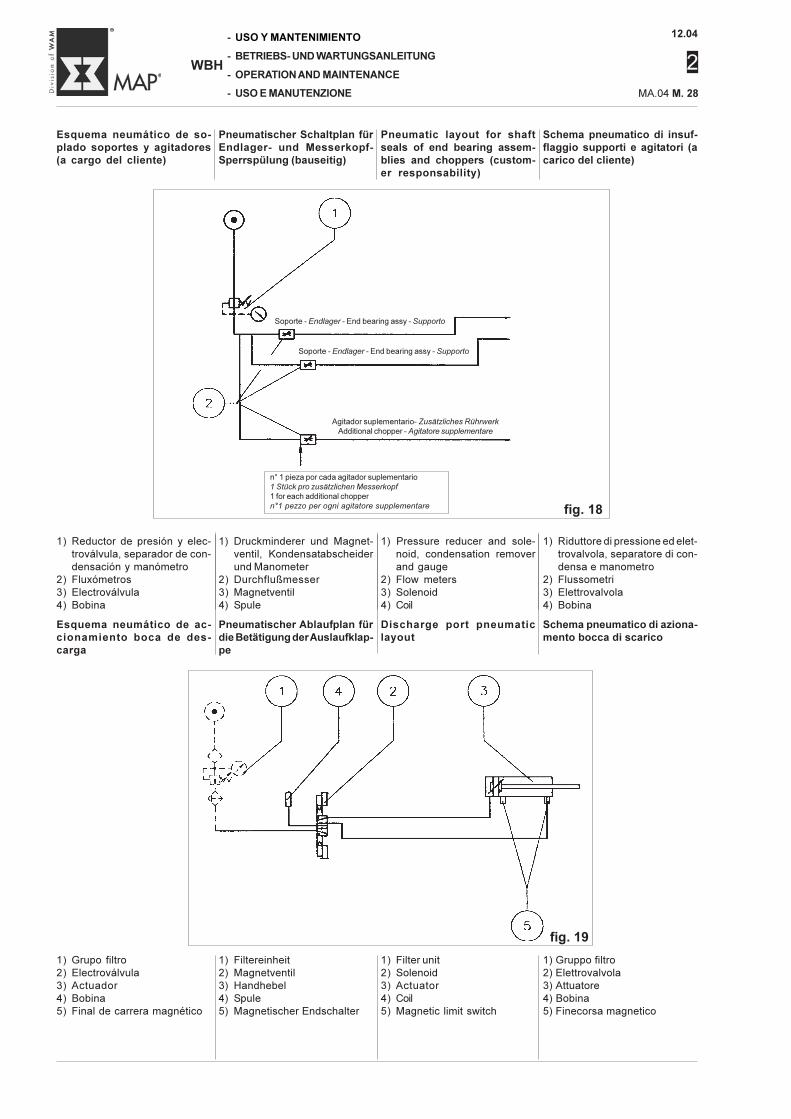
Schema pneumatico di insuf-flaggio supporti e agitatori (acarico del cliente)
Pneumatic layout for shaftseals of end bearing assem-blies and choppers (custom-er responsability)
Pneumatischer Schaltplan fürEndlager- und Messerkopf-Sperrspülung (bauseitig)
Esquema neumático de so-plado soportes y agitadores(a cargo del cliente)
1) Filter unit2) Solenoid3) Actuator4) Coil5) Magnetic limit switch
1) Gruppo filtro2) Elettrovalvola3) Attuatore4) Bobina5) Finecorsa magnetico
1) Filtereinheit2) Magnetventil3) Handhebel4) Spule5) Magnetischer Endschalter
1) Grupo filtro2) Electroválvula3) Actuador4) Bobina5) Final de carrera magnético
Esquema neumático de ac-cionamiento boca de des-carga
Pneumatischer Ablaufplan fürdie Betätigung der Auslaufklap-pe
Discharge port pneumaticlayout
Schema pneumatico di aziona-mento bocca di scarico
fig. 19
1) Druckminderer und Magnet-ventil, Kondensatabscheiderund Manometer
2) Durchflußmesser3) Magnetventil4) Spule
1) Riduttore di pressione ed elet-trovalvola, separatore di con-densa e manometro
2) Flussometri3) Elettrovalvola4) Bobina
1) Reductor de presión y elec-troválvula, separador de con-densación y manómetro
2) Fluxómetros3) Electroválvula4) Bobina
1) Pressure reducer and sole-noid, condensation removerand gauge
2) Flow meters3) Solenoid4) Coil
Soporte - Endlager - End bearing assy - Supporto
Agitador suplementario- Zusätzliches RührwerkAdditional chopper - Agitatore supplementare
n° 1 pieza por cada agitador suplementario
1 Stück pro zusätzlichen Messerkopf1 for each additional chopper
n°1 pezzo per ogni agitatore supplementare fig. 18
Soporte - Endlager - End bearing assy - Supporto
12.04
2
MA.04 M. 29
-
-
-
-
WBH
USO Y MANTENIMIENTO
BETRIEBS- UND WARTUNGSANLEITUNG
OPERATION AND MAINTENANCE
USO E MANUTENZIONE
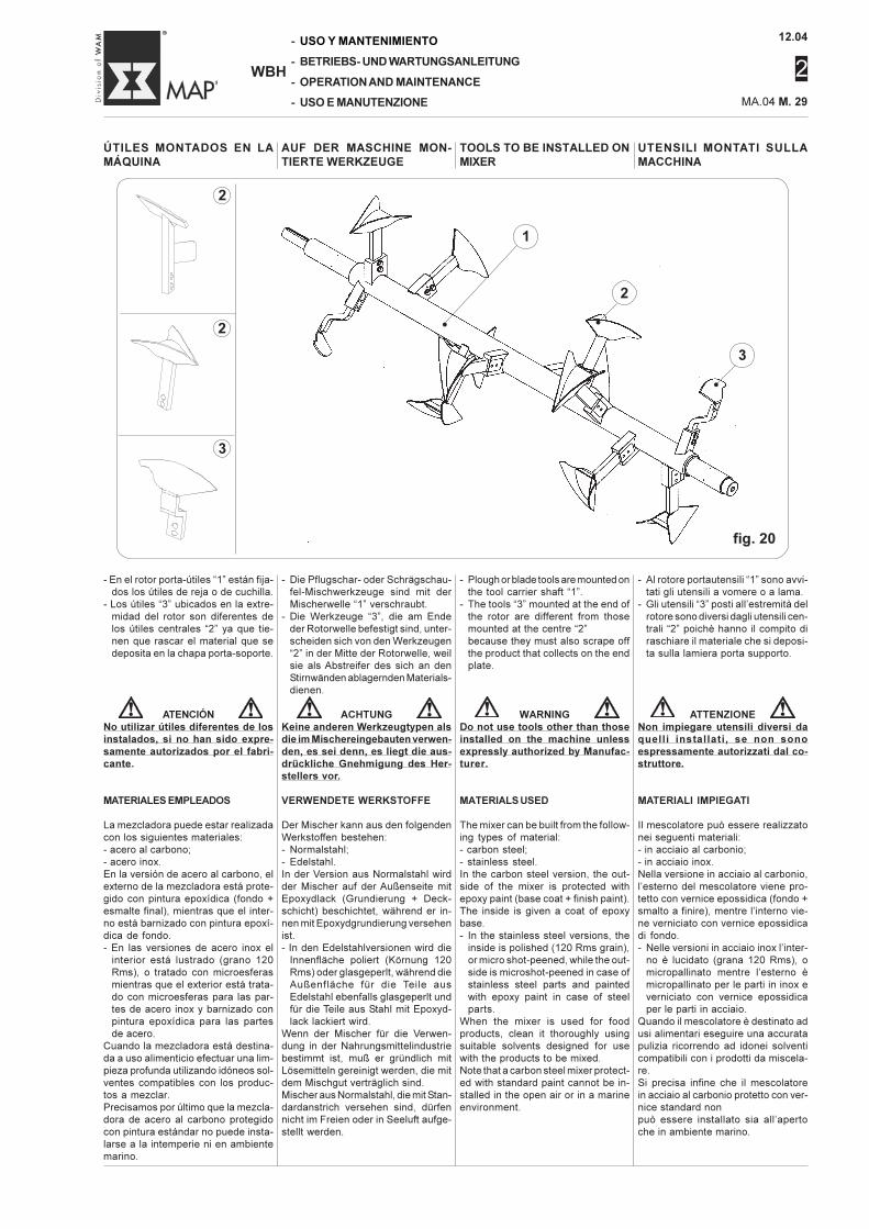
UTENSILI MONTATI SULLAMACCHINA
TOOLS TO BE INSTALLED ONMIXER
AUF DER MASCHINE MON-TIERTE WERKZEUGE
ÚTILES MONTADOS EN LAMÁQUINA
- Al rotore portautensili “1” sono avvi-tati gli utensili a vomere o a lama.
- Gli utensili “3” posti all’estremità delrotore sono diversi dagli utensili cen-trali “2” poichè hanno il compito diraschiare il materiale che si deposi-ta sulla lamiera porta supporto.
ATTENZIONENon impiegare utensili diversi daquelli installati, se non sonoespressamente autorizzati dal co-struttore.
MATERIALI IMPIEGATI
Il mescolatore può essere realizzatonei seguenti materiali:- in acciaio al carbonio;- in acciaio inox.Nella versione in acciaio al carbonio,l’esterno del mescolatore viene pro-tetto con vernice epossidica (fondo +smalto a finire), mentre l’interno vie-ne verniciato con vernice epossidicadi fondo.- Nelle versioni in acciaio inox l’inter-
no è lucidato (grana 120 Rms), omicropallinato mentre l’esterno èmicropallinato per le parti in inox everniciato con vernice epossidicaper le parti in acciaio.
Quando il mescolatore è destinato adusi alimentari eseguire una accuratapulizia ricorrendo ad idonei solventicompatibili con i prodotti da miscela-re.Si precisa infine che il mescolatorein acciaio al carbonio protetto con ver-nice standard nonpuò essere installato sia all’apertoche in ambiente marino.
- Plough or blade tools are mounted onthe tool carrier shaft “1”.
- The tools “3” mounted at the end ofthe rotor are different from thosemounted at the centre “2”because they must also scrape offthe product that collects on the endplate.
WARNINGDo not use tools other than thoseinstalled on the machine unlessexpressly authorized by Manufac-turer.
MATERIALS USED
The mixer can be built from the follow-ing types of material:- carbon steel;- stainless steel.In the carbon steel version, the out-side of the mixer is protected withepoxy paint (base coat + finish paint).The inside is given a coat of epoxybase.- In the stainless steel versions, the
inside is polished (120 Rms grain),or micro shot-peened, while the out-side is microshot-peened in case ofstainless steel parts and paintedwith epoxy paint in case of steelparts.
When the mixer is used for foodproducts, clean it thoroughly usingsuitable solvents designed for usewith the products to be mixed.Note that a carbon steel mixer protect-ed with standard paint cannot be in-stalled in the open air or in a marineenvironment.
- Die Pflugschar- oder Schrägschau-fel-Mischwerkzeuge sind mit derMischerwelle “1” verschraubt.
- Die Werkzeuge “3”, die am Endeder Rotorwelle befestigt sind, unter-scheiden sich von den Werkzeugen“2” in der Mitte der Rotorwelle, weilsie als Abstreifer des sich an denStirnwänden ablagernden Materials-dienen.
ACHTUNGKeine anderen Werkzeugtypen alsdie im Mischereingebauten verwen-den, es sei denn, es liegt die aus-drückliche Gnehmigung des Her-stellers vor.
VERWENDETE WERKSTOFFE
Der Mischer kann aus den folgendenWerkstoffen bestehen:- Normalstahl;- Edelstahl.In der Version aus Normalstahl wirdder Mischer auf der Außenseite mitEpoxydlack (Grundierung + Deck-schicht) beschichtet, während er in-nen mit Epoxydgrundierung versehenist.- In den Edelstahlversionen wird die
Innenfläche poliert (Körnung 120Rms) oder glasgeperlt, während dieAußenfläche für die Teile ausEdelstahl ebenfalls glasgeperlt undfür die Teile aus Stahl mit Epoxyd-lack lackiert wird.
Wenn der Mischer für die Verwen-dung in der Nahrungsmittelindustriebestimmt ist, muß er gründlich mitLösemitteln gereinigt werden, die mitdem Mischgut verträglich sind.Mischer aus Normalstahl, die mit Stan-dardanstrich versehen sind, dürfennicht im Freien oder in Seeluft aufge-stellt werden.
- En el rotor porta-útiles “1” están fija-dos los útiles de reja o de cuchilla.
- Los útiles “3” ubicados en la extre-midad del rotor son diferentes delos útiles centrales “2” ya que tie-nen que rascar el material que sedeposita en la chapa porta-soporte.
ATENCIÓNNo utilizar útiles diferentes de losinstalados, si no han sido expre-samente autorizados por el fabri-cante.
MATERIALES EMPLEADOS
La mezcladora puede estar realizadacon los siguientes materiales:- acero al carbono;- acero inox.En la versión de acero al carbono, elexterno de la mezcladora está prote-gido con pintura epoxídica (fondo +esmalte final), mientras que el inter-no está barnizado con pintura epoxí-dica de fondo.- En las versiones de acero inox el
interior está lustrado (grano 120Rms), o tratado con microesferasmientras que el exterior está trata-do con microesferas para las par-tes de acero inox y barnizado conpintura epoxídica para las partesde acero.
Cuando la mezcladora está destina-da a uso alimenticio efectuar una lim-pieza profunda utilizando idóneos sol-ventes compatibles con los produc-tos a mezclar.Precisamos por último que la mezcla-dora de acero al carbono protegidocon pintura estándar no puede insta-larse a la intemperie ni en ambientemarino.
fig. 20
1
•
2
•
3
•
2
2
3
12.04
2
-
-
-
-
WBH
USO Y MANTENIMIENTO
BETRIEBS- UND WARTUNGSANLEITUNG
OPERATION AND MAINTENANCE
USO E MANUTENZIONE MA.04 M. 30
COLLAUDO
La macchina in Vostro posses-so è stata collaudata presso inostri stabilimenti per verificareil corretto funzionamento di tuttele parti in movimento.Durante tale collaudo vengonoeffettuate prove a vuoto per unperiodo di un’ora.
CONSEGNA E DIMENSIONIDELL'IMBALLO
Tutto il materiale, sia che vengaspedito a parte, sia che vengaspedito già installato sul misce-latore, è stato accuratamentecontrollato prima della consegnaallo spedizioniere.Alla consegna dell’imballo, veri-ficare l’integrità del contenuto.In presenza di componenti dan-neggiati sporgere immediatamen-te reclamo allo spedizioniere ecomunque non oltre i due giornilavorativi.In mancanza di diversi accordi,la macchina viene consegnataavvolta in un film di nylon termo-retraente ed ancorata ad un ban-cale in legno così da agevolarnela presa e il trasporto.
Su specifica richiesta il costrut-tore è in grado di consegnare lamacchina con altri tipi di imballo;in questo caso verificare il pesodella macchina e dell’imballo daidocumenti di trasporto.
STOCCAGGIODELLA MACCHINA
Nel caso che la macchina nonvenga installata in tempi brevioccorre depositarla al riparo dal-le intemperie in ambiente nonsoggetto ad umidità, a forti sbal-zi termici e non accessibile a per-sone non autorizzate.Accertarsi che il piano sul qualeviene appoggiata la macchina siain grado di sostenerla in sicu-rezza.
DIMENSIONI E PESO DELLAMACCHINA IMBALLATA
Controllare il peso della macchi-na imballata sui documenti dispedizione, poichè le dimensio-ni della macchina variano in re-lazione alle diverse combinazio-ni costruttive.
PUEBAS EN FABRICA
La máquina en su poder ha sidosometida e ensayos en nuestroestablecimiento para verificar elcorrecto funcionamiento de to-das las partes en movimiento.Durante dichos ensayos se hanefectuado pruebas en vacío du-rante un periodo de una hora.
ENTREGA Y DIMENSIONES DELEMBALAJE
Todo el material, que se envíaseparadamente, o ya instaladoen la mezcladora, ha sido es-crupulosamente controlado an-tes de entregarlo al transportis-ta.En el momento de la entrega delembalaje, verificar la integridaddel contenido.Si se advierten componentesdañados efectuar inmediata-mente el reclamo al transportis-ta y siempre dentro de dos díaslaborables.Si no existen acuerdos diferen-tes, la máquina se entrega en-vuelta en una película de nailontermorretráctil y fijada a una pa-leta de madera para facilitar lasujeción y el transporte.
Bajo específico pedido el fabri-cante puede enviar la máquinacon otros tipos de embalaje; eneste caso verificar el peso de lamáquina y del embalaje en losdocumentos de transporte.
ALMACENAMIENTO DE LAMÁQUINA
En el caso que la máquina no seinstale en breve tiempo es ne-cesario depositarla protegida dela intemperie en ambiente no su-jeto a humedad, ni a bruscoscambios térmicos y no accesi-ble a personas no autorizadas.Controlar que el plano donde seapoya la máquina pueda soste-nerla en modo seguro.
DIMENSIONES Y PESO DE LAMÁQUINA EMBALADA
Controlar el peso de la máquinaembalada en los documentos deexpedición, pues las dimensio-nes de la máquina cambian enrelación de las diferentes com-binaciones constructivas.
WERKSSEITIGE TESTS
Die in Ihrem Besitz befindlicheMaschine wurde im Hersteller-werkauf korrekte Funktion allerbeweglichen Teile geprüft.Während dieser Prüfung wurdeein einstündiger Leerlauftestdurchgeführt.
LIEFERUNG UND KOLLIMAS-SE
Vor der Übernahme durch denSpediteur wurden sämtliche Lie-ferpositionen (montierte und un-montierte Teile) sorgfältig auf ihreVollständigkeit geprüft.Bei der Anlieferung der verpack-ten Ware prüfen, ob diese unver-sehrt ist.Falls Teile beschädigt sind, sofortbeim Spediteur reklamieren, je-doch keinesfalls später als zweiArbeitstage nach Anlieferung.Wenn nicht anderes vereinbartist, wird die Maschine auf einerHolzpalette verankert und mitSchrumpffolie verpackt, um dasHandling zu erleichtern.
Auf spezifische Anfrage ist derHersteller in der Lage, die Ma-schine in anderen Verpackungs-arten zu liefern. In diesem Falldas Gewicht der Maschine undder Verpackung den Frachtdoku-menten entnehmen.
LAGERUNGDER MASCHINE
Falls die Maschine nicht binnenkurzer Zeit eingebaut wird, ist eserforderlich, sie vor Witterungs-einflüssen geschützt in trockenerUmgebung ohne große Tempe-raturschwankungen und nicht zu-gänglich für nicht autorisiertesPersonal unterzubringen.Stellen sie sicher, daß die Unter-lage, auf der die Maschine abge-stellt wird rutschfest ist und ihrGewicht sicher trägt.
KOLLIABMESSUNGEN UND-GEWICHTE
Das Kolligewicht in den Fracht-dokumenten kontrollieren, da dieAbmessungen der Maschine inAbhängigkeit der konstruktivenVersion variieren.
FACTORY TESTS
The machine in your possessionhas been tested at our factory toverify that all moving parts func-tion properly.
During these tests, off-load runshave been carried out for ap-proximately one hour.
DELIVERY AND PACKINGDIMENSIONS
All materials, whether deliveredapart or delivered already mount-ed on the mixer, have been accu-rately inspected before beingcollected by the shipping agent.At delivery, verify the integrity ofthe contents.If any components have beendamaged, complaints must be im-mediately presented to the ship-ping agent within two workingdays.Unless other agreements havebeen made, the machine is deliv-ered wrapped in a heat-shrinkfoil and anchored to a woodenpallet, in order to facilitate han-dling and transport
Upon specific request of the Cli-ent, the Manufacturer can deliv-er the machine in any other typeof packing. In this case, verifythe weight of the machine and ofthe packing in the shipping doc-uments.
STORINGTHE MACHINE
If the machine is not immediatelyinstalled, it must be stored in anarea that is protected from in-clement weather, moisture, ex-treme temperature changes, andwhere it is not accessible to un-authorised personnel.Make sure that the floor ontowhich the machine is placed isable to safely support it.
DIMENSIONS AND WEIGHT OFPACKED MACHINE
Check the weight of the packedmachine in the shipping docu-ments, since the machine dimen-sions vary according to the ver-sion.
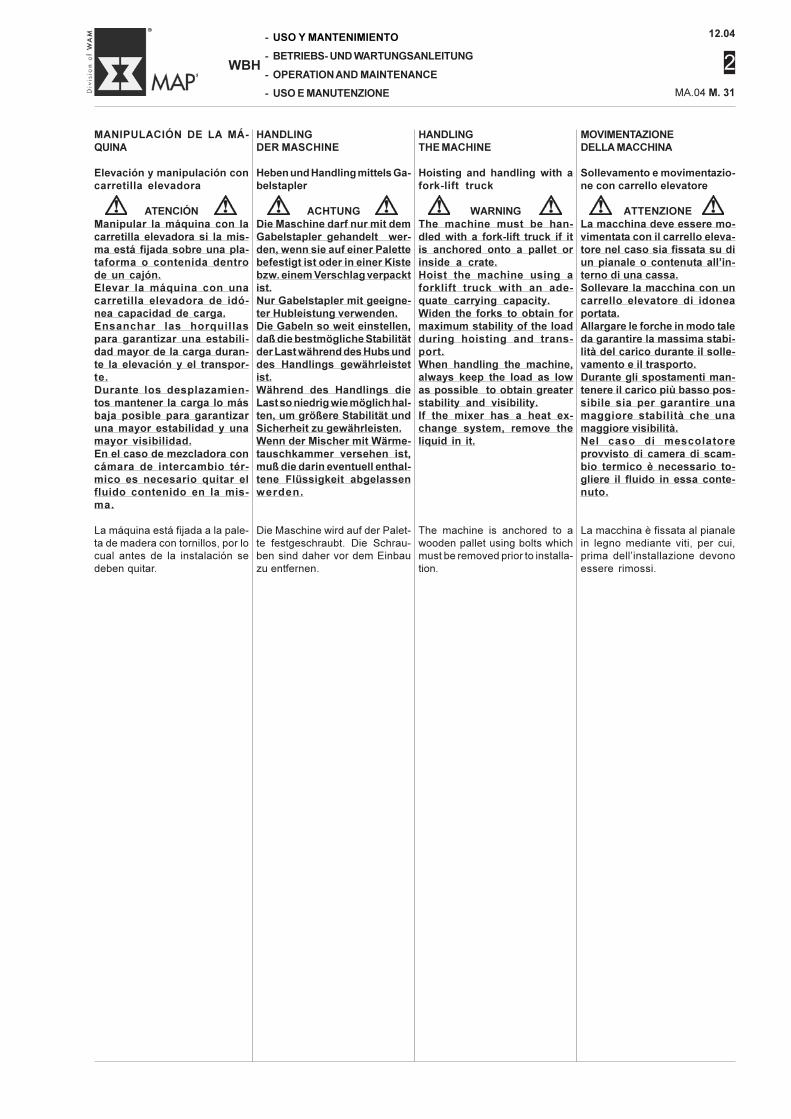
12.04
2
MA.04 M. 31
-
-
-
-
WBH
USO Y MANTENIMIENTO
BETRIEBS- UND WARTUNGSANLEITUNG
OPERATION AND MAINTENANCE
USO E MANUTENZIONE
MOVIMENTAZIONEDELLA MACCHINA
Sollevamento e movimentazio-ne con carrello elevatore
ATTENZIONELa macchina deve essere mo-vimentata con il carrello eleva-tore nel caso sia fissata su diun pianale o contenuta all’in-terno di una cassa.Sollevare la macchina con uncarrello elevatore di idoneaportata.Allargare le forche in modo taleda garantire la massima stabi-lità del carico durante il solle-vamento e il trasporto.Durante gli spostamenti man-tenere il carico più basso pos-sibile sia per garantire unamaggiore stabilità che unamaggiore visibilità.Nel caso di mescolatoreprovvisto di camera di scam-bio termico è necessario to-gliere il fluido in essa conte-nuto.
La macchina è fissata al pianalein legno mediante viti, per cui,prima dell’installazione devonoessere rimossi.
HANDLINGTHE MACHINE
Hoisting and handling with afork-lift truck
WARNINGThe machine must be han-dled with a fork-lift truck if itis anchored onto a pallet orinside a crate.Hoist the machine using aforklift truck with an ade-quate carrying capacity.Widen the forks to obtain formaximum stability of the loadduring hoisting and trans-port.When handling the machine,always keep the load as lowas possible to obtain greaterstability and visibility.If the mixer has a heat ex-change system, remove theliquid in it.
The machine is anchored to awooden pallet using bolts whichmust be removed prior to installa-tion.
HANDLINGDER MASCHINE
Heben und Handling mittels Ga-belstapler
ACHTUNGDie Maschine darf nur mit demGabelstapler gehandelt wer-den, wenn sie auf einer Palettebefestigt ist oder in einer Kistebzw. einem Verschlag verpacktist.Nur Gabelstapler mit geeigne-ter Hubleistung verwenden.Die Gabeln so weit einstellen,daß die bestmögliche Stabilitätder Last während des Hubs unddes Handlings gewährleistetist.Während des Handlings dieLast so niedrig wie möglich hal-ten, um größere Stabilität undSicherheit zu gewährleisten.Wenn der Mischer mit Wärme-tauschkammer versehen ist,muß die darin eventuell enthal-tene Flüssigkeit abgelassenwerden.
Die Maschine wird auf der Palet-te festgeschraubt. Die Schrau-ben sind daher vor dem Einbauzu entfernen.
MANIPULACIÓN DE LA MÁ-QUINA
Elevación y manipulación concarretilla elevadora
ATENCIÓNManipular la máquina con lacarretilla elevadora si la mis-ma está fijada sobre una pla-taforma o contenida dentrode un cajón.Elevar la máquina con unacarretilla elevadora de idó-nea capacidad de carga.Ensanchar las horquillaspara garantizar una estabili-dad mayor de la carga duran-te la elevación y el transpor-te.Durante los desplazamien-tos mantener la carga lo másbaja posible para garantizaruna mayor estabilidad y unamayor visibilidad.En el caso de mezcladora concámara de intercambio tér-mico es necesario quitar elfluido contenido en la mis-ma.
La máquina está fijada a la pale-ta de madera con tornillos, por locual antes de la instalación sedeben quitar.
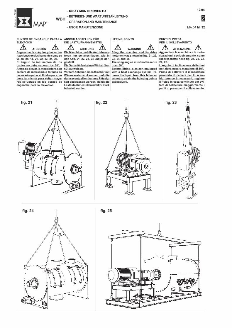
12.04
2
-
-
-
-
WBH
USO Y MANTENIMIENTO
BETRIEBS- UND WARTUNGSANLEITUNG
OPERATION AND MAINTENANCE
USO E MANUTENZIONE MA.04 M. 32
ATENCIÓNEnganchar la máquina y las moto-rizaciones exclusivamente como seve en las fig. 21, 22, 23, 24, 25.El ángulo de inclinación de loscables no debe superar los 60°.Antes de elevar la mezcladora concámara de intercambio térmico esnecesario quitar el fluido que con-tiene la misma para evitar mayo-res esfuerzos en los puntos deenganche para la elevación.
ATTENZIONEAgganciare la macchina e le moto-rizzazioni esclusivamente comerappresentato nelle fig. 21, 22, 23,24, 25.L’angolo di inclinazione delle funinon deve essere maggiore di 60°.Prima di sollevare il mescolatoreprovvisto di camera per lo scam-bio termico è necessario togliereil fluido in essa contenuto per evi-tare di sollecitare maggiormente ipunti di presa per il sollevamento.
WARNINGSling the machine and its drivemotor only as shown in figs. 21, 22,23, 24 and 25.The sling angles must not be morethan 60°.Before lifting a mixer equippedwith a heat exchange system, re-move the liquid from this latter soas not to strain the hoisting pointsexcessively.
ACHTUNGDie Maschine und die Antriebsmo-toren nur so anschlagen, wie inden Abb. 21, 22, 23, 24 und 25 dar-gestellt.Die Gurte dürfen keinen Winkel über60° aufweisen.Vordem Anheben eines Mischer mitWärmeaustauschkammer muß diedarin eventuell enthaltene Flüssig-keit abgelassen werden, damit dieLastaufnahmestellen nicht zu starkbelastet werden.
PUNTI DI PRESAPER IL SOLLEVAMENTO
LIFTING POINTSANSCHLAGSTELLEN FÜRDIE LASTAUFNAHMEMITTEL
PUNTOS DE ENGANCHE PARA LAELEVACIÓN
fig. 21 fig. 22 fig. 23
fig. 24 fig. 25
12.04
2
MA.04 M. 33
-
-
-
-
WBH
USO Y MANTENIMIENTO
BETRIEBS- UND WARTUNGSANLEITUNG
OPERATION AND MAINTENANCE
USO E MANUTENZIONE
DISIMBALLO E SMALTIMENTODEGLI IMBALLI
Liberare la macchina dal nylonche la avvolge, dal pianale o daqualsiasi altro imballo esistentericordando che per il loro smalti-mento occorre seguire la legisla-zione locale e che:
- il nylon, se bruciato, producefumi tossici;
- il pianale, come ogni altro imbal-lo in legno, può essere riutiliz-zato ma non può essere reso.
Lista materiale in dotazioneAll’interno dell’imballo è presen-te il seguente materiale:- n°2 libretti “catalogo parti di ri-
cambio”;- n°2 libretti “Manuale Uso e Ma-
nutenzione”;- n°1 barattolo di vernice epossi-
dica con la quale è stato verni-ciato il mescolatore.
UNPACKING AND DISPOSAL OFPACKING MATERIAL
Remove the nylon wrapping fromthe machine, along with the palletor any other packaging materialused, and remember that thesematerials must be disposed off inaccordance with the local laws.Also bear in mind that:
- the nylon film, if burned, pro-duces toxic fumes;
- the pallet, such as any otherwooden packing material, canbe reused.
List of material suppliedThe following material is con-tained inside the packing:- 2 “Spare Parts Catalogue” man-
uals;- 2 “Instruction Manual” manuals;- 1 can of epoxy paint used to
paint the mixer.
AUSPACKEN UND ENTSOR-GUNG DER VERPACKUNGEN
Die Maschine von der Nylonhül-le, der Palette und allen anderenVerpackungselementen befreien.Die Verpackung muss gemäß dervor Ort geltenden Bestimmungenentsorgt werden. Außerdem istzu beachten, dass:
- Folie, wenn sie verbrannt wird,giftige Rauchgase entwickelt
- die Palette, wie jede andereHolzverpackung wiederverwen-det werden kann.
Im Lieferumfang inbegriffenIm Inneren der Verpackung be-finden sich:- 2 Ersatzteillisten- 2 Bedienungs-und Wartungs-
anleitungen- 1 Dose Epoxydlack im Farbton
des Mischers.
DESEMBALAJE Y ELIMINA-CIÓN DE LOS EMBALAJES
Quitar el nylon que envuelve lamáquina, sacar la máquina de laplataforma o de cualquier emba-laje existente recordando quepara su eliminación es necesa-rio seguir las indicaciones de lalegislación local y que:
- el nylon, al quemarse, producehumos tóxicos;
- la plataforma, como todo em-balaje de madera, se puedevolver a utilizar pero no se res-tituye.
Lista material de serieDentro del embalaje se encuen-tra el siguiente material:- n°2 manuales “catálogo re-
puestos”;- n°2 manuales “Manual de Uso
y Mantenimiento”;- n°1 bote de pintura epoxídica
con la cual se ha barnizado lamezcladora.
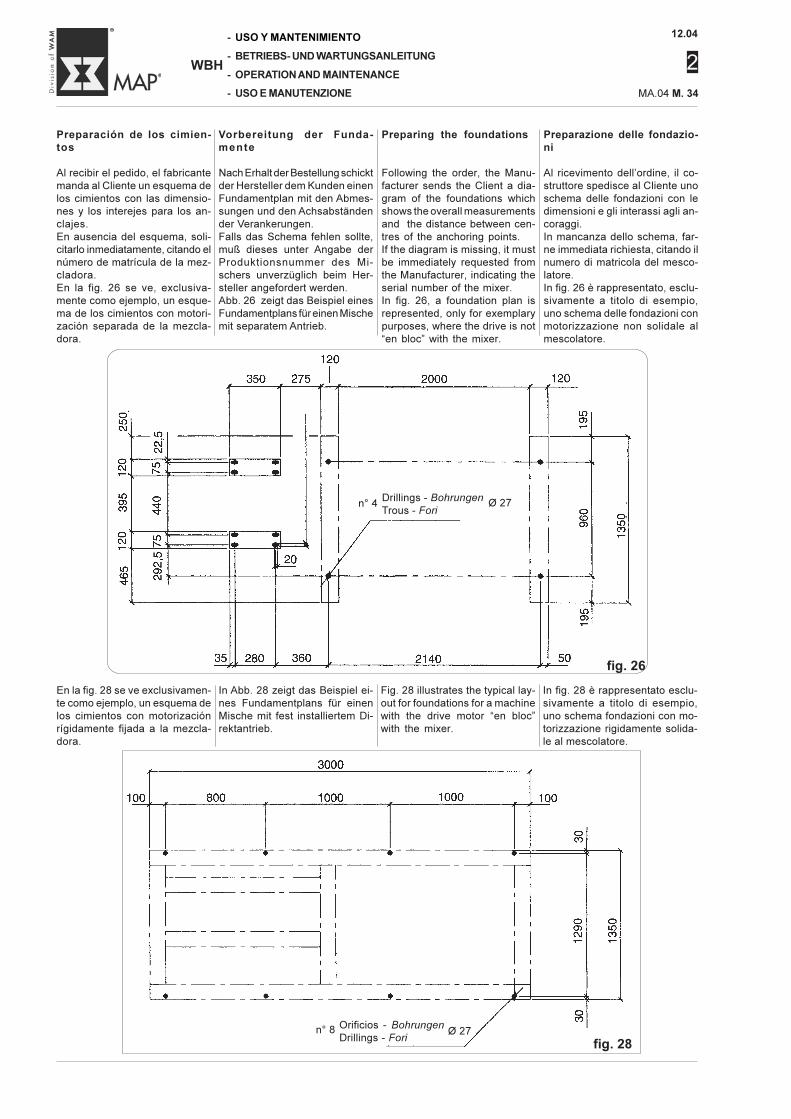
12.04
2
-
-
-
-
WBH
USO Y MANTENIMIENTO
BETRIEBS- UND WARTUNGSANLEITUNG
OPERATION AND MAINTENANCE
USO E MANUTENZIONE MA.04 M. 34
Preparazione delle fondazio-ni
Al ricevimento dell’ordine, il co-struttore spedisce al Cliente unoschema delle fondazioni con ledimensioni e gli interassi agli an-coraggi.In mancanza dello schema, far-ne immediata richiesta, citando ilnumero di matricola del mesco-latore.In fig. 26 è rappresentato, esclu-sivamente a titolo di esempio,uno schema delle fondazioni conmotorizzazione non solidale almescolatore.
Preparación de los cimien-tos
Al recibir el pedido, el fabricantemanda al Cliente un esquema delos cimientos con las dimensio-nes y los interejes para los an-clajes.En ausencia del esquema, soli-citarlo inmediatamente, citando elnúmero de matrícula de la mez-cladora.En la fig. 26 se ve, exclusiva-mente como ejemplo, un esque-ma de los cimientos con motori-zación separada de la mezcla-dora.
Vorbereitung der Funda-mente
Nach Erhalt der Bestellung schicktder Hersteller dem Kunden einenFundamentplan mit den Abmes-sungen und den Achsabständender Verankerungen.Falls das Schema fehlen sollte,muß dieses unter Angabe derProduktionsnummer des Mi-schers unverzüglich beim Her-steller angefordert werden.Abb. 26 zeigt das Beispiel einesFundamentplans für einen Mischemit separatem Antrieb.
Preparing the foundations
Following the order, the Manu-facturer sends the Client a dia-gram of the foundations whichshows the overall measurementsand the distance between cen-tres of the anchoring points.If the diagram is missing, it mustbe immediately requested fromthe Manufacturer, indicating theserial number of the mixer.In fig. 26, a foundation plan isrepresented, only for exemplarypurposes, where the drive is not“en bloc” with the mixer.
En la fig. 28 se ve exclusivamen-te como ejemplo, un esquema delos cimientos con motorizaciónrígidamente fijada a la mezcla-dora.
In fig. 28 è rappresentato esclu-sivamente a titolo di esempio,uno schema fondazioni con mo-torizzazione rigidamente solida-le al mescolatore.
Fig. 28 illustrates the typical lay-out for foundations for a machinewith the drive motor “en bloc”with the mixer.
In Abb. 28 zeigt das Beispiel ei-nes Fundamentplans für einenMische mit fest installiertem Di-rektantrieb.
n° 4 Ø 27
n° 8 Orificios - Bohrungen
Drillings - ForiØ 27
fig. 26
fig. 28
Drillings - Bohrungen
Trous - Fori
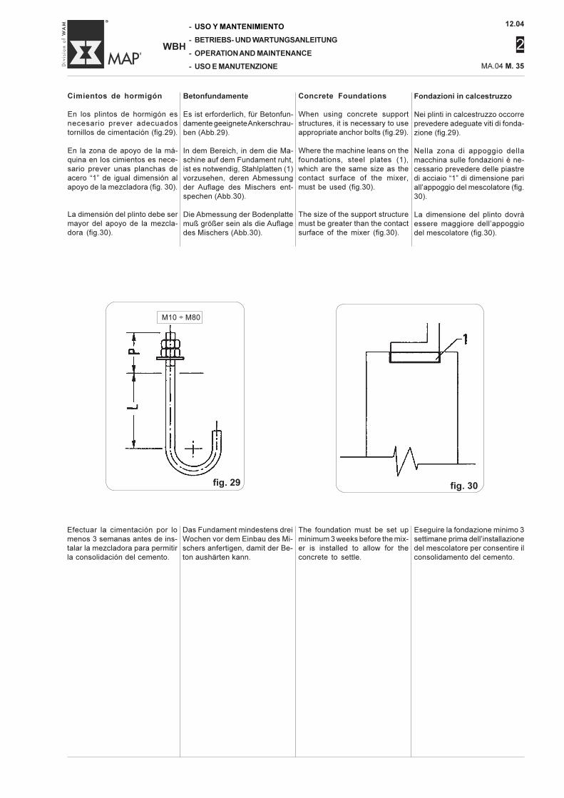
12.04
2
MA.04 M. 35
-
-
-
-
WBH
USO Y MANTENIMIENTO
BETRIEBS- UND WARTUNGSANLEITUNG
OPERATION AND MAINTENANCE
USO E MANUTENZIONE
Fondazioni in calcestruzzo
Nei plinti in calcestruzzo occorreprevedere adeguate viti di fonda-zione (fig.29).
Nella zona di appoggio dellamacchina sulle fondazioni è ne-cessario prevedere delle piastredi acciaio “1” di dimensione pariall’appoggio del mescolatore (fig.30).
La dimensione del plinto dovràessere maggiore dell’appoggiodel mescolatore (fig.30).
Cimientos de hormigón
En los plintos de hormigón esnecesario prever adecuadostornillos de cimentación (fig.29).
En la zona de apoyo de la má-quina en los cimientos es nece-sario prever unas planchas deacero “1” de igual dimensión alapoyo de la mezcladora (fig. 30).
La dimensión del plinto debe sermayor del apoyo de la mezcla-dora (fig.30).
Betonfundamente
Es ist erforderlich, für Betonfun-damente geeignete Ankerschrau-ben (Abb.29).
In dem Bereich, in dem die Ma-schine auf dem Fundament ruht,ist es notwendig, Stahlplatten (1)vorzusehen, deren Abmessungder Auflage des Mischers ent-spechen (Abb.30).
Die Abmessung der Bodenplattemuß größer sein als die Auflagedes Mischers (Abb.30).
Concrete Foundations
When using concrete supportstructures, it is necessary to useappropriate anchor bolts (fig.29).
Where the machine leans on thefoundations, steel plates (1),which are the same size as thecontact surface of the mixer,must be used (fig.30).
The size of the support structuremust be greater than the contactsurface of the mixer (fig.30).
Eseguire la fondazione minimo 3settimane prima dell’installazionedel mescolatore per consentire ilconsolidamento del cemento.
Efectuar la cimentación por lomenos 3 semanas antes de ins-talar la mezcladora para permitirla consolidación del cemento.
Das Fundament mindestens dreiWochen vor dem Einbau des Mi-schers anfertigen, damit der Be-ton aushärten kann.
The foundation must be set upminimum 3 weeks before the mix-er is installed to allow for theconcrete to settle.
M10 ÷ M80
fig. 29 fig. 30
12.04
2
-
-
-
-
WBH
USO Y MANTENIMIENTO
BETRIEBS- UND WARTUNGSANLEITUNG
OPERATION AND MAINTENANCE
USO E MANUTENZIONE MA.04 M. 36
Fondazioni in carpenteria me-tallica
Se la macchina viene installatain quota, la struttura di sostegnoè generalmente in profilati metal-lici.
ATTENZIONEVerificare staticamente e dina-micamente le travi in relazioneal tipo di montaggio.
Prevedere la foratura rappresen-tata nel disegno fondazioni condiametro di due misure superiorialle viti di fissaggio del mescola-tore con lo scopo di facilitare ilmontaggio.
ATTENZIONENon saldare la motorizzazioneo il mescolatore o entrambi allefondazioni in carpenteria, poi-ché le vibrazioni non garanti-scono un bloccaggio sicuro.
NotaNel dimensionamento della strut-tura di sostegno tenere conto dieventuali ulteriori carichi come adesempio tramogge.Se tali carichi sono solidali al me-scolatore dovranno essere con-vertiti in dinamici.
Cimientos de estructurametálica
Si la máquina se instala en posi-ción elevada, la estructura desostén es generalmente de per-files metálicos.
ATENCIÓNVerificar estática y dinámica-mente las vigas en relaciónal tipo de montaje.
Prever la perforación represen-tada en la ilustración cimientoscon un diámetro de dos medidassuperiores de los tornillos de fi-jación de la mezcladora con lafinalidad de facilitar el montaje.
ATENCIÓNNo soldar la motorización ola mezcladora ni ambas enlos cimientos de la estruc-tura, pues las vibraciones nogarantizan un bloqueo segu-ro.
NotaAl dimensionar la estructura desostén tener en cuenta eventua-les ulteriores cargas como porejemplo tolvas.Si dichas cargas son parte fijade la mezcladora se deben con-vertir en dinámicas.
Stahlfundamente
Wenn die Maschine in größererHöhe eingebaut wird, besteht dieAuflage in der Regel aus Metall-profilen.
ACHTUNGDie Traversen statisch und dy-namisch in bezug auf die Ein-bauform überprüfen.
Wenn die Fundamentblöcke ausStahl angefertigt sind, die Boh-rungen so vozursehen wie in denFundamentzeichnungen darge-stellt, und zwar mit einem Durch-messer um zwei Größen größerals die Befestigungsschraubendes Mischers, um die Montagezu vereinfachen.
ACHTUNGWeder den Antriebsmotor se-parat, noch den Mischer, nochbeide zusammen mit den Stahl-fundamenten verschweißen, dainfolge Vibrationen Risse auf-treten können.
HinweisBei der Größenauslegung derFundamentblöcke sind etwaigeweitere Belastungen durch Auf-satztrichter und Schneckenförde-rer zu berücksichtigen.Wenn diese Lasten fest am Mi-scher montiert werden, müssensie in dynamische Belastungenumgewandelt werden.
Fabricated Foundations
If the machine is installed at anelevated height, there is usuallya fabricated supporting struc-ture.
WARNINGVerify the static and dynamicconditions of the beams inrelation to the type of mount-ing procedure carried out.
Drill the holes as shown in thefoundation drawing two sizeslarger than the anchoring bolts tofacilitate installation.
WARNINGDo not weld the drive motor,mixer or both to the fabricat-ed foundation because vibra-tion will not guarantee surefixing.
NoteWhen calculating the size of thesupport structure, take any addi-tional load factors such as hop-pers into account. If these loadsapply “en bloc” to the mixer, theymust be converted into dynamicloads.
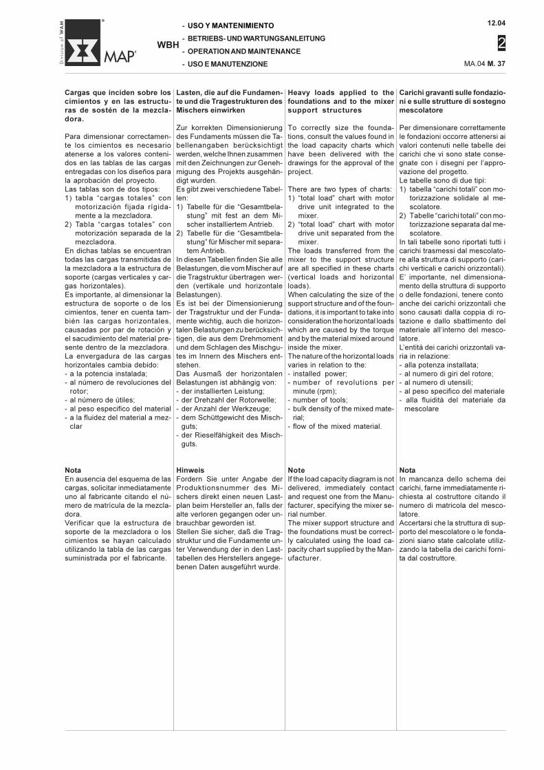
12.04
2
MA.04 M. 37
-
-
-
-
WBH
USO Y MANTENIMIENTO
BETRIEBS- UND WARTUNGSANLEITUNG
OPERATION AND MAINTENANCE
USO E MANUTENZIONE
Carichi gravanti sulle fondazio-ni e sulle strutture di sostegnomescolatore
Per dimensionare correttamentele fondazioni occorre attenersi aivalori contenuti nelle tabelle deicarichi che vi sono state conse-gnate con i disegni per l’appro-vazione del progetto.Le tabelle sono di due tipi:1) tabella “carichi totali” con mo-
torizzazione solidale al me-scolatore.
2) Tabelle “carichi totali” con mo-torizzazione separata dal me-scolatore.
In tali tabelle sono riportati tutti icarichi trasmessi dal mescolato-re alla struttura di supporto (cari-chi verticali e carichi orizzontali).E’ importante, nel dimensiona-mento della struttura di supportoo delle fondazioni, tenere contoanche dei carichi orizzontali chesono causati dalla coppia di ro-tazione e dallo sbattimento delmateriale all’interno del mesco-latore.L’entità dei carichi orizzontali va-ria in relazione:- alla potenza installata;- al numero di giri del rotore;- al numero di utensili;- al peso specifico del materiale- alla fluidità del materiale da
mescolare
NotaIn mancanza dello schema deicarichi, farne immediatamente ri-chiesta al costruttore citando ilnumero di matricola del mesco-latore.Accertarsi che la struttura di sup-porto del mescolatore o le fonda-zioni siano state calcolate utiliz-zando la tabella dei carichi forni-ta dal costruttore.
Cargas que inciden sobre loscimientos y en las estructu-ras de sostén de la mezcla-dora.
Para dimensionar correctamen-te los cimientos es necesarioatenerse a los valores conteni-dos en las tablas de las cargasentregadas con los diseños parala aprobación del proyecto.Las tablas son de dos tipos:1) tabla “cargas totales” con
motorización fijada rígida-mente a la mezcladora.
2) Tabla “cargas totales” conmotorización separada de lamezcladora.
En dichas tablas se encuentrantodas las cargas transmitidas dela mezcladora a la estructura desoporte (cargas verticales y car-gas horizontales).Es importante, al dimensionar laestructura de soporte o de loscimientos, tener en cuenta tam-bién las cargas horizontales,causadas por par de rotación yel sacudimiento del material pre-sente dentro de la mezcladora.La envergadura de las cargashorizontales cambia debido:- a la potencia instalada;- al número de revoluciones del
rotor;- al número de útiles;- al peso especifico del material- a la fluidez del material a mez-
clar
NotaEn ausencia del esquema de lascargas, solicitar inmediatamenteuno al fabricante citando el nú-mero de matrícula de la mezcla-dora.Verificar que la estructura desoporte de la mezcladora o loscimientos se hayan calculadoutilizando la tabla de las cargassuministrada por el fabricante.
Heavy loads applied to thefoundations and to the mixersupport structures
To correctly size the founda-tions, consult the values found inthe load capacity charts whichhave been delivered with thedrawings for the approval of theproject.
There are two types of charts:1) “total load” chart with motor
drive unit integrated to themixer.
2) “total load” chart with motordrive unit separated from themixer.
The loads transferred from themixer to the support structureare all specified in these charts(vertical loads and horizontalloads).When calculating the size of thesupport structure and of the foun-dations, it is important to take intoconsideration the horizontal loadswhich are caused by the torqueand by the material mixed aroundinside the mixer.The nature of the horizontal loadsvaries in relation to the:- installed power;- number of revolutions per
minute (rpm);- number of tools;- bulk density of the mixed mate-
rial;- flow of the mixed material.
NoteIf the load capacity diagram is notdelivered, immediately contactand request one from the Manu-facturer, specifying the mixer se-rial number.The mixer support structure andthe foundations must be correct-ly calculated using the load ca-pacity chart supplied by the Man-ufacturer.
Lasten, die auf die Fundamen-te und die Tragestrukturen desMischers einwirken
Zur korrekten Dimensionierungdes Fundaments müssen die Ta-bellenangaben berücksichtigtwerden, welche Ihnen zusammenmit den Zeichnungen zur Geneh-migung des Projekts ausgehän-digt wurden.Es gibt zwei verschiedene Tabel-len:1) Tabelle für die “Gesamtbela-
stung” mit fest an dem Mi-scher installiertem Antrieb.
2) Tabelle für die “Gesamtbela-stung” für Mischer mit separa-tem Antrieb.
In diesen Tabellen finden Sie alleBelastungen, die vom Mischer aufdie Tragstruktur übertragen wer-den (vertikale und horizontaleBelastungen).Es ist bei der Dimensionierungder Tragstruktur und der Funda-mente wichtig, auch die horizon-talen Belastungen zu berücksich-tigen, die aus dem Drehmomentund dem Schlagen des Mischgu-tes im Innern des Mischers ent-stehen.Das Ausmaß der horizontalenBelastungen ist abhängig von:- der installierten Leistung;- der Drehzahl der Rotorwelle;- der Anzahl der Werkzeuge;- dem Schüttgewicht des Misch-
guts;- der Rieselfähigkeit des Misch-
guts.
HinweisFordern Sie unter Angabe derProduktionsnummer des Mi-schers direkt einen neuen Last-plan beim Hersteller an, falls deralte verloren gegangen oder un-brauchbar geworden ist.Stellen Sie sicher, daß die Trag-struktur und die Fundamente un-ter Verwendung der in den Last-tabellen des Herstellers angege-benen Daten ausgeführt wurde.
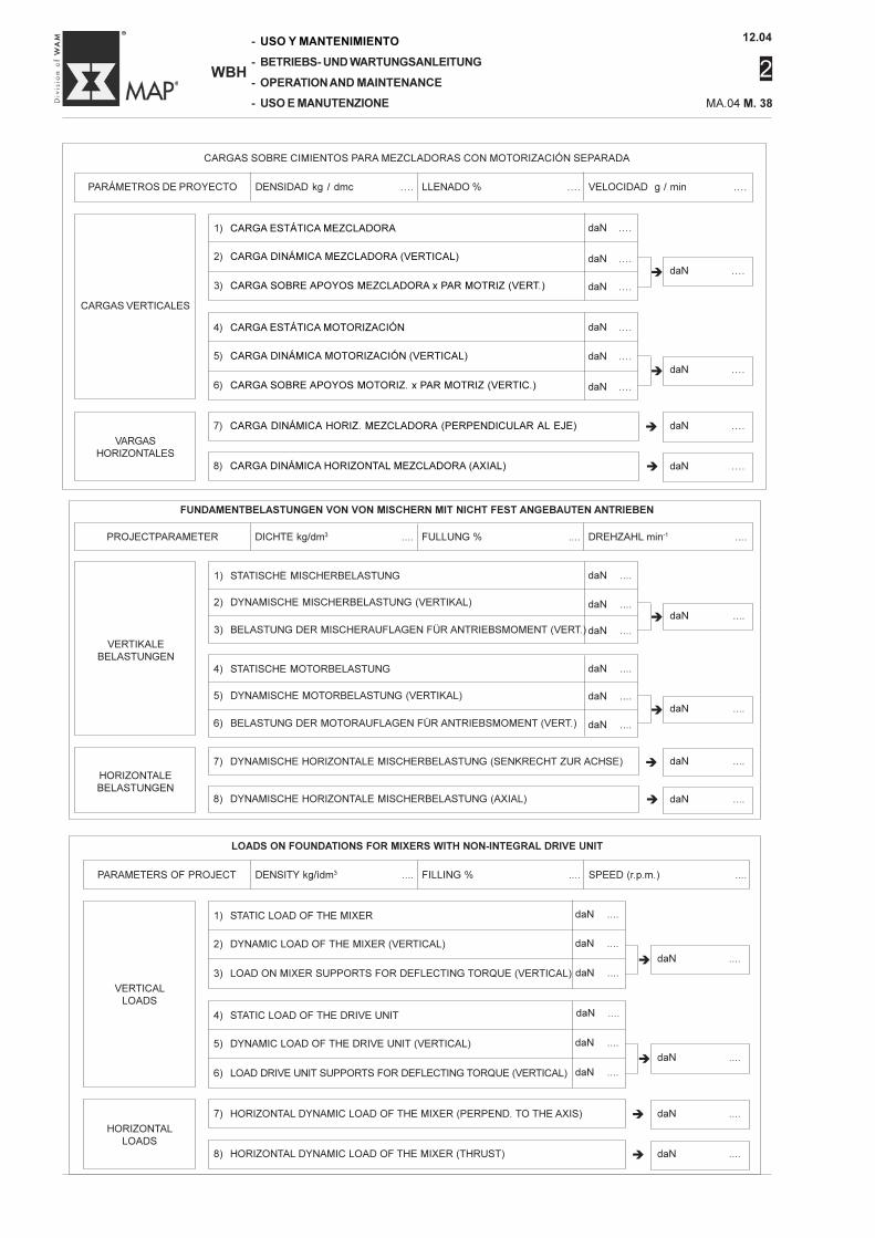
12.04
2
-
-
-
-
WBH
USO Y MANTENIMIENTO
BETRIEBS- UND WARTUNGSANLEITUNG
OPERATION AND MAINTENANCE
USO E MANUTENZIONE MA.04 M. 38
FUNDAMENTBELASTUNGEN VON VON MISCHERN MIT NICHT FEST ANGEBAUTEN ANTRIEBEN
PROJECTPARAMETER DICHTE kg/dm3 .... FULLUNG % .... DREHZAHL min-1 ....
VERTIKALEBELASTUNGEN
HORIZONTALEBELASTUNGEN
7) DYNAMISCHE HORIZONTALE MISCHERBELASTUNG (SENKRECHT ZUR ACHSE)
8) DYNAMISCHE HORIZONTALE MISCHERBELASTUNG (AXIAL)
�
�
daN ....
� daN ....
daN ....
� daN ....
1) STATISCHE MISCHERBELASTUNG
2) DYNAMISCHE MISCHERBELASTUNG (VERTIKAL)
3) BELASTUNG DER MISCHERAUFLAGEN FÜR ANTRIEBSMOMENT (VERT.)
4) STATISCHE MOTORBELASTUNG
5) DYNAMISCHE MOTORBELASTUNG (VERTIKAL)
6) BELASTUNG DER MOTORAUFLAGEN FÜR ANTRIEBSMOMENT (VERT.)
daN ....
daN ....
daN ....
daN ....
daN ....
daN ....
LOADS ON FOUNDATIONS FOR MIXERS WITH NON-INTEGRAL DRIVE UNIT
PARAMETERS OF PROJECT DENSITY kg/ìdm3 .... FILLING % .... SPEED (r.p.m.) ....
1) STATIC LOAD OF THE MIXER
2) DYNAMIC LOAD OF THE MIXER (VERTICAL)
3) LOAD ON MIXER SUPPORTS FOR DEFLECTING TORQUE (VERTICAL)
4) STATIC LOAD OF THE DRIVE UNIT
5) DYNAMIC LOAD OF THE DRIVE UNIT (VERTICAL)
6) LOAD DRIVE UNIT SUPPORTS FOR DEFLECTING TORQUE (VERTICAL)
VERTICALLOADS
HORIZONTALLOADS
7) HORIZONTAL DYNAMIC LOAD OF THE MIXER (PERPEND. TO THE AXIS)
8) HORIZONTAL DYNAMIC LOAD OF THE MIXER (THRUST)
�
�
daN ....
� daN ....
daN ....
� daN ....
daN ....
daN ....
daN ....
daN ....
daN ....
daN ....
CARGAS SOBRE CIMIENTOS PARA MEZCLADORAS CON MOTORIZACIÓN SEPARADA
PARÁMETROS DE PROYECTO DENSIDAD kg / dmc .... LLENADO % .... VELOCIDAD g / min ....
CARGAS VERTICALES
VARGASHORIZONTALES
7) CARGA DINÁMICA HORIZ. MEZCLADORA (PERPENDICULAR AL EJE)
8) CARGA DINÁMICA HORIZONTAL MEZCLADORA (AXIAL)
�
�
daN ....
� daN ....
daN ....
� daN ....
1) CARGA ESTÁTICA MEZCLADORA
2) CARGA DINÁMICA MEZCLADORA (VERTICAL)
3) CARGA SOBRE APOYOS MEZCLADORA x PAR MOTRIZ (VERT.)
4) CARGA ESTÁTICA MOTORIZACIÓN
5) CARGA DINÁMICA MOTORIZACIÓN (VERTICAL)
6) CARGA SOBRE APOYOS MOTORIZ. x PAR MOTRIZ (VERTIC.)
daN ....
daN ....
daN ....
daN ....
daN ....
daN ....
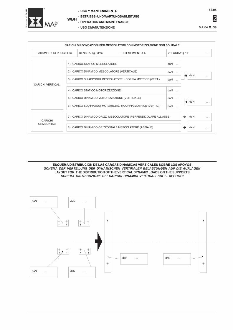
12.04
2
MA.04 M. 39
-
-
-
-
WBH
USO Y MANTENIMIENTO
BETRIEBS- UND WARTUNGSANLEITUNG
OPERATION AND MAINTENANCE
USO E MANUTENZIONE
ESQUEMA DISTRIBUCIÓN DE LAS CARGAS DINÁMICAS VERTICALES SOBRE LOS APOYOSSCHEMA DER VERTEILUNG DER DYNAMISCHEN VERTIKALEN BELASTUNGEN AUF DIE AUFLAGEN
LAYOUT FOR THE DISTRIBUTION OF THE VERTICAL DYNAMIC LOADS ON THE SUPPORTSSCHEMA DISTRIBUZIONE DEI CARICHI DINAMICI VERTICALI SUGLI APPOGGI
CARICHI SU FONDAZIONI PER MESCOLATORI CON MOTORIZZAZIONE NON SOLIDALE
PARAMETRI DI PROGETTO DENSITA' kg / dmc .... RIEMPIMENTO % .... VELOCITA' g / 1’ ....
CARICHI VERTICALI
CARICHIORIZZONTALI
7) CARICO DINAMICO ORIZZ. MESCOLATORE (PERPENDICOLARE ALL'ASSE)
8) CARICO DINAMICO ORIZZONTALE MESCOLATORE (ASSIALE)
�
�
daN ....
� daN ....
daN ....
� daN ....
1) CARICO STATICO MESCOLATORE
2) CARICO DINAMICO MESCOLATORE (VERTICALE)
3) CARICO SU APPOGGI MESCOLATORE x COPPIA MOTRICE (VERT.)
4) CARICO STATICO MOTORIZZAZIONE
5) CARICO DINAMICO MOTORIZZAZIONE (VERTICALE)
6) CARICO SU APPOGGI MOTORIZZAZ. x COPPIA MOTRICE (VERTIC.)
daN ....
daN ....
daN ....
daN ....
daN ....
daN ....
daN .... daN ....
daN .... daN ....
daN .... daN ....
• •
• •
• •
• •
• •
• •
• •
• •
•
•
•
•
••
•
•
•
•
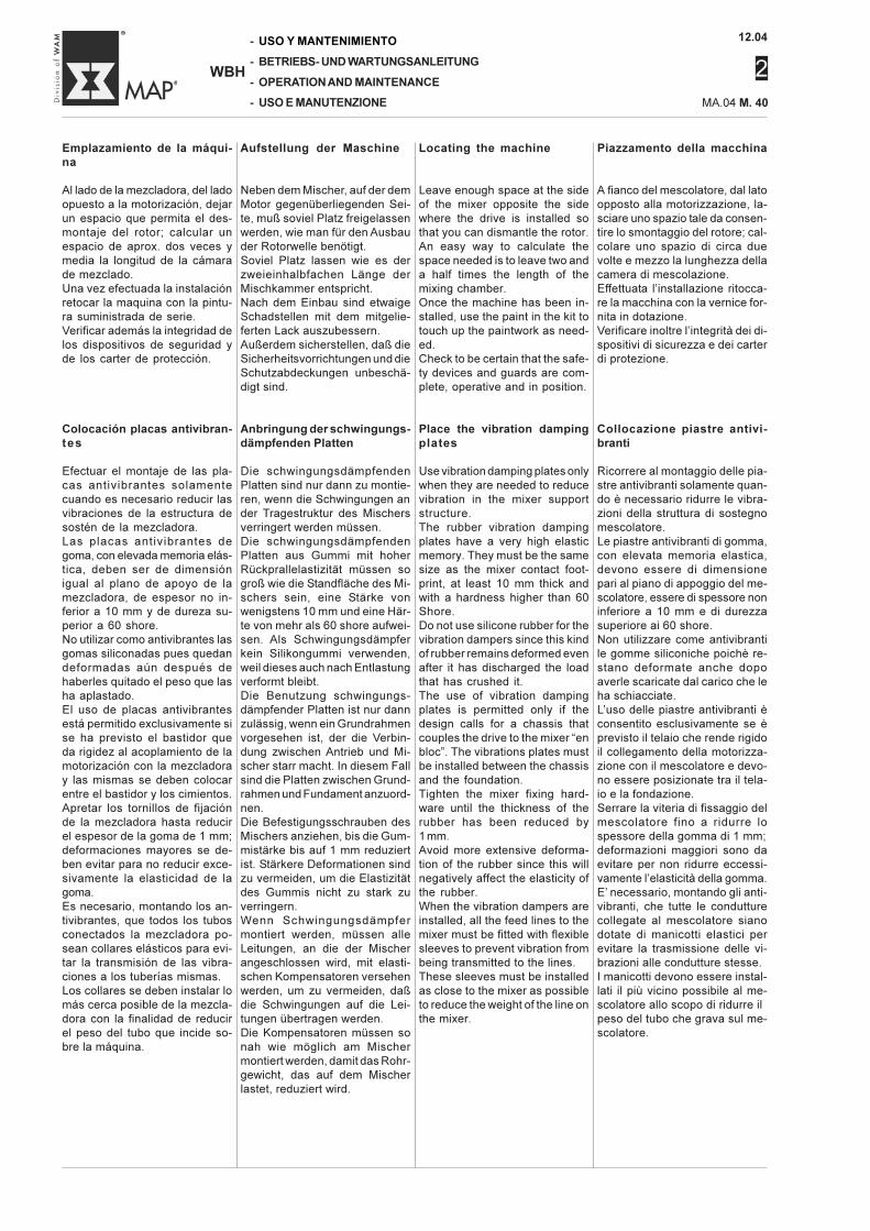
12.04
2
-
-
-
-
WBH
USO Y MANTENIMIENTO
BETRIEBS- UND WARTUNGSANLEITUNG
OPERATION AND MAINTENANCE
USO E MANUTENZIONE MA.04 M. 40
Piazzamento della macchina
A fianco del mescolatore, dal latoopposto alla motorizzazione, la-sciare uno spazio tale da consen-tire lo smontaggio del rotore; cal-colare uno spazio di circa duevolte e mezzo la lunghezza dellacamera di mescolazione.Effettuata l’installazione ritocca-re la macchina con la vernice for-nita in dotazione.Verificare inoltre l’integrità dei di-spositivi di sicurezza e dei carterdi protezione.
Collocazione piastre antivi-branti
Ricorrere al montaggio delle pia-stre antivibranti solamente quan-do è necessario ridurre le vibra-zioni della struttura di sostegnomescolatore.Le piastre antivibranti di gomma,con elevata memoria elastica,devono essere di dimensionepari al piano di appoggio del me-scolatore, essere di spessore noninferiore a 10 mm e di durezzasuperiore ai 60 shore.Non utilizzare come antivibrantile gomme siliconiche poichè re-stano deformate anche dopoaverle scaricate dal carico che leha schiacciate.L’uso delle piastre antivibranti èconsentito esclusivamente se èprevisto il telaio che rende rigidoil collegamento della motorizza-zione con il mescolatore e devo-no essere posizionate tra il tela-io e la fondazione.Serrare la viteria di fissaggio delmescolatore fino a ridurre lospessore della gomma di 1 mm;deformazioni maggiori sono daevitare per non ridurre eccessi-vamente l’elasticità della gomma.E’ necessario, montando gli anti-vibranti, che tutte le condutturecollegate al mescolatore sianodotate di manicotti elastici perevitare la trasmissione delle vi-brazioni alle condutture stesse.I manicotti devono essere instal-lati il più vicino possibile al me-scolatore allo scopo di ridurre ilpeso del tubo che grava sul me-scolatore.
Locating the machine
Leave enough space at the sideof the mixer opposite the sidewhere the drive is installed sothat you can dismantle the rotor.An easy way to calculate thespace needed is to leave two anda half times the length of themixing chamber.Once the machine has been in-stalled, use the paint in the kit totouch up the paintwork as need-ed.Check to be certain that the safe-ty devices and guards are com-plete, operative and in position.
Place the vibration dampingplates
Use vibration damping plates onlywhen they are needed to reducevibration in the mixer supportstructure.The rubber vibration dampingplates have a very high elasticmemory. They must be the samesize as the mixer contact foot-print, at least 10 mm thick andwith a hardness higher than 60Shore.Do not use silicone rubber for thevibration dampers since this kindof rubber remains deformed evenafter it has discharged the loadthat has crushed it.The use of vibration dampingplates is permitted only if thedesign calls for a chassis thatcouples the drive to the mixer “enbloc”. The vibrations plates mustbe installed between the chassisand the foundation.Tighten the mixer fixing hard-ware until the thickness of therubber has been reduced by1 mm.Avoid more extensive deforma-tion of the rubber since this willnegatively affect the elasticity ofthe rubber.When the vibration dampers areinstalled, all the feed lines to themixer must be fitted with flexiblesleeves to prevent vibration frombeing transmitted to the lines.These sleeves must be installedas close to the mixer as possibleto reduce the weight of the line onthe mixer.
Aufstellung der Maschine
Neben dem Mischer, auf der demMotor gegenüberliegenden Sei-te, muß soviel Platz freigelassenwerden, wie man für den Ausbauder Rotorwelle benötigt.Soviel Platz lassen wie es derzweieinhalbfachen Länge derMischkammer entspricht.Nach dem Einbau sind etwaigeSchadstellen mit dem mitgelie-ferten Lack auszubessern.Außerdem sicherstellen, daß dieSicherheitsvorrichtungen und dieSchutzabdeckungen unbeschä-digt sind.
Anbringung der schwingungs-dämpfenden Platten
Die schwingungsdämpfendenPlatten sind nur dann zu montie-ren, wenn die Schwingungen ander Tragestruktur des Mischersverringert werden müssen.Die schwingungsdämpfendenPlatten aus Gummi mit hoherRückprallelastizität müssen sogroß wie die Standfläche des Mi-schers sein, eine Stärke vonwenigstens 10 mm und eine Här-te von mehr als 60 shore aufwei-sen. Als Schwingungsdämpferkein Silikongummi verwenden,weil dieses auch nach Entlastungverformt bleibt.Die Benutzung schwingungs-dämpfender Platten ist nur dannzulässig, wenn ein Grundrahmenvorgesehen ist, der die Verbin-dung zwischen Antrieb und Mi-scher starr macht. In diesem Fallsind die Platten zwischen Grund-rahmen und Fundament anzuord-nen.Die Befestigungsschrauben desMischers anziehen, bis die Gum-mistärke bis auf 1 mm reduziertist. Stärkere Deformationen sindzu vermeiden, um die Elastizitätdes Gummis nicht zu stark zuverringern.Wenn Schwingungsdämpfermontiert werden, müssen alleLeitungen, an die der Mischerangeschlossen wird, mit elasti-schen Kompensatoren versehenwerden, um zu vermeiden, daßdie Schwingungen auf die Lei-tungen übertragen werden.Die Kompensatoren müssen sonah wie möglich am Mischermontiert werden, damit das Rohr-gewicht, das auf dem Mischerlastet, reduziert wird.
Emplazamiento de la máqui-na
Al lado de la mezcladora, del ladoopuesto a la motorización, dejarun espacio que permita el des-montaje del rotor; calcular unespacio de aprox. dos veces ymedia la longitud de la cámarade mezclado.Una vez efectuada la instalaciónretocar la maquina con la pintu-ra suministrada de serie.Verificar además la integridad delos dispositivos de seguridad yde los carter de protección.
Colocación placas antivibran-tes
Efectuar el montaje de las pla-cas antivibrantes solamentecuando es necesario reducir lasvibraciones de la estructura desostén de la mezcladora.Las placas antivibrantes degoma, con elevada memoria elás-tica, deben ser de dimensiónigual al plano de apoyo de lamezcladora, de espesor no in-ferior a 10 mm y de dureza su-perior a 60 shore.No utilizar como antivibrantes lasgomas siliconadas pues quedandeformadas aún después dehaberles quitado el peso que lasha aplastado.El uso de placas antivibrantesestá permitido exclusivamente sise ha previsto el bastidor queda rigidez al acoplamiento de lamotorización con la mezcladoray las mismas se deben colocarentre el bastidor y los cimientos.Apretar los tornillos de fijaciónde la mezcladora hasta reducirel espesor de la goma de 1 mm;deformaciones mayores se de-ben evitar para no reducir exce-sivamente la elasticidad de lagoma.Es necesario, montando los an-tivibrantes, que todos los tubosconectados la mezcladora po-sean collares elásticos para evi-tar la transmisión de las vibra-ciones a los tuberías mismas.Los collares se deben instalar lomás cerca posible de la mezcla-dora con la finalidad de reducirel peso del tubo que incide so-bre la máquina.
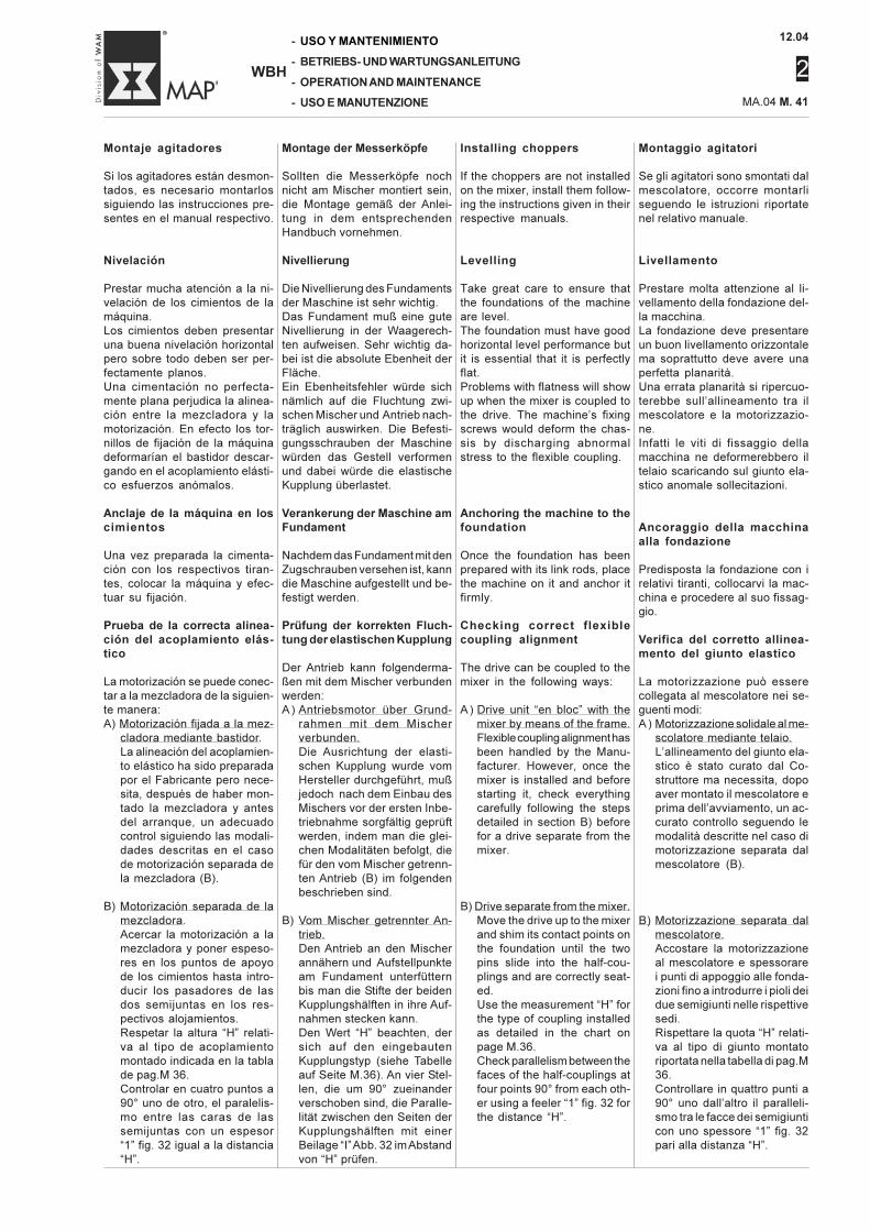
12.04
2
MA.04 M. 41
-
-
-
-
WBH
USO Y MANTENIMIENTO
BETRIEBS- UND WARTUNGSANLEITUNG
OPERATION AND MAINTENANCE
USO E MANUTENZIONE
Montaggio agitatori
Se gli agitatori sono smontati dalmescolatore, occorre montarliseguendo le istruzioni riportatenel relativo manuale.
Livellamento
Prestare molta attenzione al li-vellamento della fondazione del-la macchina.La fondazione deve presentareun buon livellamento orizzontalema soprattutto deve avere unaperfetta planarità.Una errata planarità si ripercuo-terebbe sull’allineamento tra ilmescolatore e la motorizzazio-ne.Infatti le viti di fissaggio dellamacchina ne deformerebbero iltelaio scaricando sul giunto ela-stico anomale sollecitazioni.
Ancoraggio della macchinaalla fondazione
Predisposta la fondazione con irelativi tiranti, collocarvi la mac-china e procedere al suo fissag-gio.
Verifica del corretto allinea-mento del giunto elastico
La motorizzazione può esserecollegata al mescolatore nei se-guenti modi:A ) Motorizzazione solidale al me-
scolatore mediante telaio.L’allineamento del giunto ela-stico è stato curato dal Co-struttore ma necessita, dopoaver montato il mescolatore eprima dell’avviamento, un ac-curato controllo seguendo lemodalità descritte nel caso dimotorizzazione separata dalmescolatore (B).
B) Motorizzazione separata dalmescolatore.Accostare la motorizzazioneal mescolatore e spessorarei punti di appoggio alle fonda-zioni fino a introdurre i pioli deidue semigiunti nelle rispettivesedi.Rispettare la quota “H” relati-va al tipo di giunto montatoriportata nella tabella di pag.M36.Controllare in quattro punti a90° uno dall’altro il paralleli-smo tra le facce dei semigiunticon uno spessore “1” fig. 32pari alla distanza “H”.
Montaje agitadores
Si los agitadores están desmon-tados, es necesario montarlossiguiendo las instrucciones pre-sentes en el manual respectivo.
Nivelación
Prestar mucha atención a la ni-velación de los cimientos de lamáquina.Los cimientos deben presentaruna buena nivelación horizontalpero sobre todo deben ser per-fectamente planos.Una cimentación no perfecta-mente plana perjudica la alinea-ción entre la mezcladora y lamotorización. En efecto los tor-nillos de fijación de la máquinadeformarían el bastidor descar-gando en el acoplamiento elásti-co esfuerzos anómalos.
Anclaje de la máquina en loscimientos
Una vez preparada la cimenta-ción con los respectivos tiran-tes, colocar la máquina y efec-tuar su fijación.
Prueba de la correcta alinea-ción del acoplamiento elás-tico
La motorización se puede conec-tar a la mezcladora de la siguien-te manera:A) Motorización fijada a la mez-
cladora mediante bastidor.La alineación del acoplamien-to elástico ha sido preparadapor el Fabricante pero nece-sita, después de haber mon-tado la mezcladora y antesdel arranque, un adecuadocontrol siguiendo las modali-dades descritas en el casode motorización separada dela mezcladora (B).
B) Motorización separada de lamezcladora.Acercar la motorización a lamezcladora y poner espeso-res en los puntos de apoyode los cimientos hasta intro-ducir los pasadores de lasdos semijuntas en los res-pectivos alojamientos.Respetar la altura “H” relati-va al tipo de acoplamientomontado indicada en la tablade pag.M 36.Controlar en cuatro puntos a90° uno de otro, el paralelis-mo entre las caras de lassemijuntas con un espesor“1” fig. 32 igual a la distancia“H”.
Installing choppers
If the choppers are not installedon the mixer, install them follow-ing the instructions given in theirrespective manuals.
Levelling
Take great care to ensure thatthe foundations of the machineare level.The foundation must have goodhorizontal level performance butit is essential that it is perfectlyflat.Problems with flatness will showup when the mixer is coupled tothe drive. The machine’s fixingscrews would deform the chas-sis by discharging abnormalstress to the flexible coupling.
Anchoring the machine to thefoundation
Once the foundation has beenprepared with its link rods, placethe machine on it and anchor itfirmly.
Checking correct flexiblecoupling alignment
The drive can be coupled to themixer in the following ways:
A) Drive unit “en bloc” with themixer by means of the frame.Flexible coupling alignment hasbeen handled by the Manu-facturer. However, once themixer is installed and beforestarting it, check everythingcarefully following the stepsdetailed in section B) beforefor a drive separate from themixer.
B) Drive separate from the mixer.Move the drive up to the mixerand shim its contact points onthe foundation until the twopins slide into the half-cou-plings and are correctly seat-ed.Use the measurement “H” forthe type of coupling installedas detailed in the chart onpage M.36.Check parallelism between thefaces of the half-couplings atfour points 90° from each oth-er using a feeler “1” fig. 32 forthe distance “H”.
Montage der Messerköpfe
Sollten die Messerköpfe nochnicht am Mischer montiert sein,die Montage gemäß der Anlei-tung in dem entsprechendenHandbuch vornehmen.
Nivellierung
Die Nivellierung des Fundamentsder Maschine ist sehr wichtig.Das Fundament muß eine guteNivellierung in der Waagerech-ten aufweisen. Sehr wichtig da-bei ist die absolute Ebenheit derFläche.Ein Ebenheitsfehler würde sichnämlich auf die Fluchtung zwi-schen Mischer und Antrieb nach-träglich auswirken. Die Befesti-gungsschrauben der Maschinewürden das Gestell verformenund dabei würde die elastischeKupplung überlastet.
Verankerung der Maschine amFundament
Nachdem das Fundament mit denZugschrauben versehen ist, kanndie Maschine aufgestellt und be-festigt werden.
Prüfung der korrekten Fluch-tung der elastischen Kupplung
Der Antrieb kann folgenderma-ßen mit dem Mischer verbundenwerden:A) Antriebsmotor über Grund-
rahmen mit dem Mischerverbunden.Die Ausrichtung der elasti-schen Kupplung wurde vomHersteller durchgeführt, mußjedoch nach dem Einbau desMischers vor der ersten Inbe-triebnahme sorgfältig geprüftwerden, indem man die glei-chen Modalitäten befolgt, diefür den vom Mischer getrenn-ten Antrieb (B) im folgendenbeschrieben sind.
B) Vom Mischer getrennter An-trieb.Den Antrieb an den Mischerannähern und Aufstellpunkteam Fundament unterfütternbis man die Stifte der beidenKupplungshälften in ihre Auf-nahmen stecken kann.Den Wert “H” beachten, dersich auf den eingebautenKupplungstyp (siehe Tabelleauf Seite M.36). An vier Stel-len, die um 90° zueinanderverschoben sind, die Paralle-lität zwischen den Seiten derKupplungshälften mit einerBeilage “I” Abb. 32 im Abstandvon “H” prüfen.
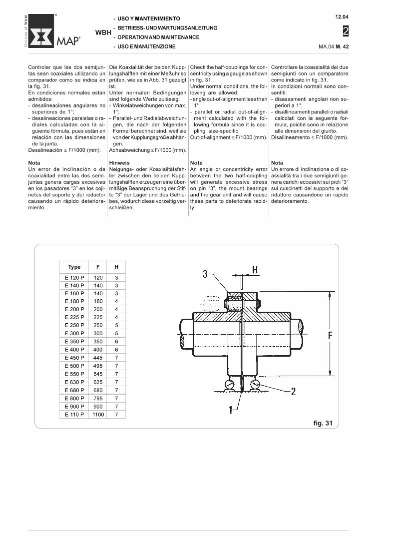
12.04
2
-
-
-
-
WBH
USO Y MANTENIMIENTO
BETRIEBS- UND WARTUNGSANLEITUNG
OPERATION AND MAINTENANCE
USO E MANUTENZIONE MA.04 M. 42
Die Koaxialität der beiden Kupp-lungshälften mit einer Meßuhr soprüfen, wie es in Abb. 31 gezeigtist.Unter normalen Bedingungensind folgende Werte zulässig:- Winkelabweichungen von max.
1°;- Parallel- und Radialabweichun-
gen, die nach der folgendenFormel berechnet sind, weil sievon der Kupplungsgröße abhän-gen.
Achsabweichung ≤ F/1000 (mm).
HinweisNeigungs- oder Koaxialitätsfeh-ler zwischen den beiden Kupp-lungshälften erzeugen eine über-mäßige Beanspruchung der Stif-te “3” der Lager und des Getrie-bes, wodurch diese vorzeitig ver-schleißen.
Controllare la coassialità dei duesemigiunti con un comparatorecome indicato in fig. 31.In condizioni normali sono con-sentiti:- disassamenti angolari non su-
periori a 1°;- disallineamenti paralleli o radiali
calcolati con la seguente for-mula, poichè sono in relazionealle dimensioni del giunto.
Disallineamento ≤ F/1000 (mm).
NotaUn errore di inclinazione o di co-assialità tra i due semigiunti ge-nera carichi eccessivi sui pioli “3”sui cuscinetti del supporto e delriduttore causandone un rapidodeterioramento.
Check the half-couplings for con-centricity using a gauge as shownin fig. 31.Under normal conditions, the fol-lowing are allowed:- angle out-of-alignment less than
1°- parallel or radial out-of-align-
ment calculated with the fol-lowing formula since it is cou-pling size-specific.
Out-of-alignment ≤ F/1000 (mm).
NoteAn angle or concentricity errorbetween the two half-couplingwill generate excessive stresson pin “3”, the mount bearingsand the gear unit and will causethese parts to deteriorate rapid-ly.
Controlar que las dos semijun-tas sean coaxiales utilizando uncomparador como se indica enla fig. 31.En condiciones normales estánadmitidos:- desalineaciones angulares no
superiores de 1°;- desalineaciones paralelas o ra-
diales calculadas con la si-guiente fórmula, pues están enrelación con las dimensionesde la junta.
Desalineación ≤ F/1000 (mm).
NotaUn error de inclinación o decoaxialidad entre las dos semi-juntas genera cargas excesivasen los pasadores “3” en los coji-netes del soporte y del reductorcausando un rápido deteriora-miento.
Type F H
E 120 P 120 3
E 140 P 140 3
E 160 P 140 3
E 180 P 180 4
E 200 P 200 4
E 225 P 225 4
E 250 P 250 5
E 300 P 300 5
E 350 P 350 6
E 400 P 400 6
E 450 P 445 7
E 500 P 495 7
E 550 P 545 7
E 630 P 625 7
E 680 P 680 7
E 800 P 795 7
E 900 P 900 7
E 110 P 1100 7
fig. 31
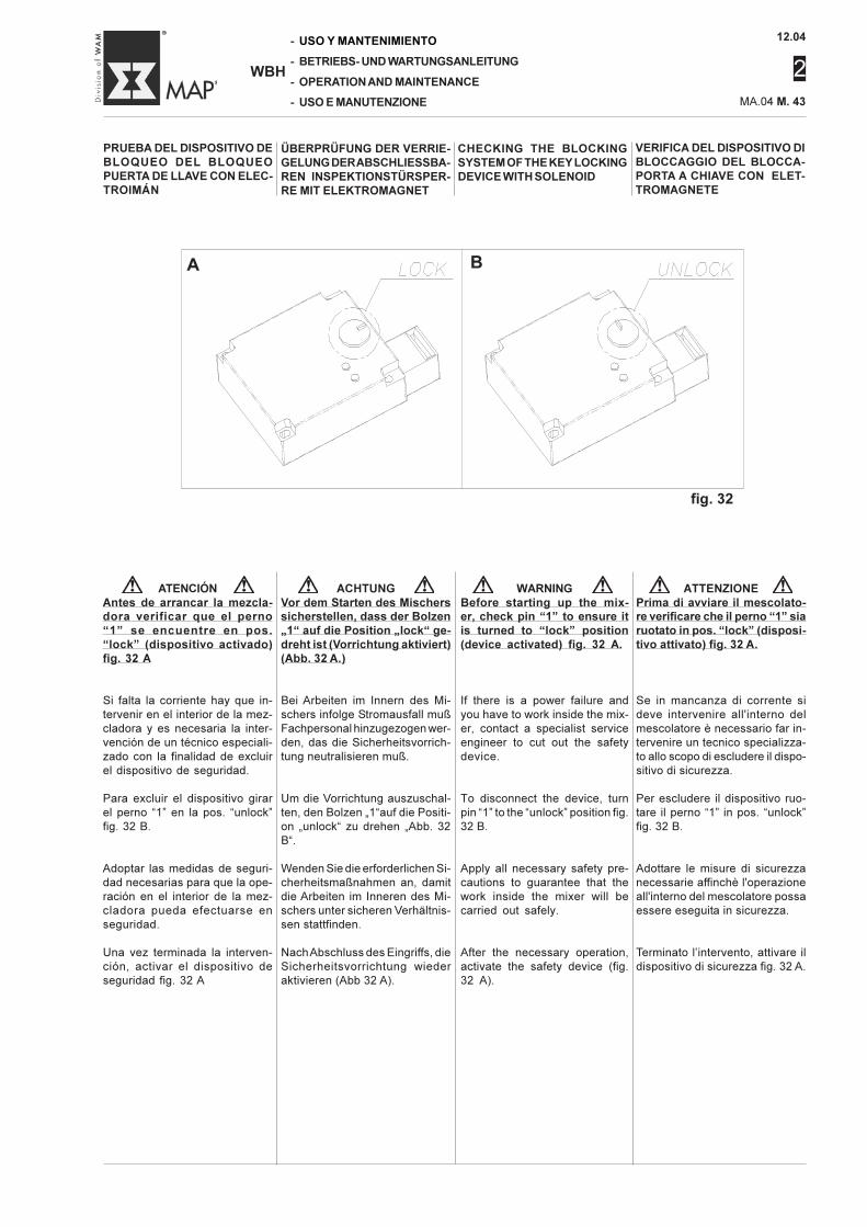
12.04
2
MA.04 M. 43
-
-
-
-
WBH
USO Y MANTENIMIENTO
BETRIEBS- UND WARTUNGSANLEITUNG
OPERATION AND MAINTENANCE
USO E MANUTENZIONE
VERIFICA DEL DISPOSITIVO DIBLOCCAGGIO DEL BLOCCA-PORTA A CHIAVE CON ELET-TROMAGNETE
PRUEBA DEL DISPOSITIVO DEBLOQUEO DEL BLOQUEOPUERTA DE LLAVE CON ELEC-TROIMÁN
ÜBERPRÜFUNG DER VERRIE-GELUNG DER ABSCHLIESSBA-REN INSPEKTIONSTÜRSPER-RE MIT ELEKTROMAGNET
CHECKING THE BLOCKINGSYSTEM OF THE KEY LOCKINGDEVICE WITH SOLENOID
fig. 32
ATTENZIONEPrima di avviare il mescolato-re verificare che il perno “1” siaruotato in pos. “lock” (disposi-tivo attivato) fig. 32 A.
Se in mancanza di corrente sideve intervenire all'interno delmescolatore è necessario far in-tervenire un tecnico specializza-to allo scopo di escludere il dispo-sitivo di sicurezza.
Per escludere il dispositivo ruo-tare il perno “1” in pos. “unlock”fig. 32 B.
Adottare le misure di sicurezzanecessarie affinchè l'operazioneall'interno del mescolatore possaessere eseguita in sicurezza.
Terminato l’intervento, attivare ildispositivo di sicurezza fig. 32 A.
ATENCIÓNAntes de arrancar la mezcla-dora verificar que el perno“1” se encuentre en pos.“lock” (dispositivo activado)fig. 32 A
Si falta la corriente hay que in-tervenir en el interior de la mez-cladora y es necesaria la inter-vención de un técnico especiali-zado con la finalidad de excluirel dispositivo de seguridad.
Para excluir el dispositivo girarel perno “1” en la pos. “unlock”fig. 32 B.
Adoptar las medidas de seguri-dad necesarias para que la ope-ración en el interior de la mez-cladora pueda efectuarse enseguridad.
Una vez terminada la interven-ción, activar el dispositivo deseguridad fig. 32 A
ACHTUNGVor dem Starten des Mischerssicherstellen, dass der Bolzen„1“ auf die Position „lock“ ge-dreht ist (Vorrichtung aktiviert)(Abb. 32 A.)
Bei Arbeiten im Innern des Mi-schers infolge Stromausfall mußFachpersonal hinzugezogen wer-den, das die Sicherheitsvorrich-tung neutralisieren muß.
Um die Vorrichtung auszuschal-ten, den Bolzen „1“auf die Positi-on „unlock“ zu drehen „Abb. 32B“.
Wenden Sie die erforderlichen Si-cherheitsmaßnahmen an, damitdie Arbeiten im Inneren des Mi-schers unter sicheren Verhältnis-sen stattfinden.
Nach Abschluss des Eingriffs, dieSicherheitsvorrichtung wiederaktivieren (Abb 32 A).
WARNINGBefore starting up the mix-er, check pin “1” to ensure itis turned to “lock” position(device activated) fig. 32 A.
If there is a power failure andyou have to work inside the mix-er, contact a specialist serviceengineer to cut out the safetydevice.
To disconnect the device, turnpin “1” to the “unlock” position fig.32 B.
Apply all necessary safety pre-cautions to guarantee that thework inside the mixer will becarried out safely.
After the necessary operation,activate the safety device (fig.32 A).
A B
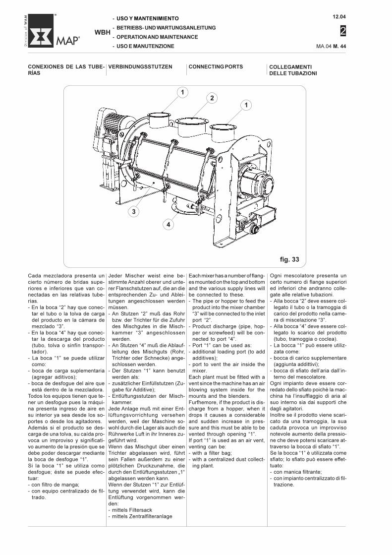
12.04
2
-
-
-
-
WBH
USO Y MANTENIMIENTO
BETRIEBS- UND WARTUNGSANLEITUNG
OPERATION AND MAINTENANCE
USO E MANUTENZIONE MA.04 M. 44
CONEXIONES DE LAS TUBE-RÍAS
Ogni mescolatore presenta uncerto numero di flange superioried inferiori che andranno colle-gate alle relative tubazioni.- Alla bocca “2” deve essere col-
legato il tubo o la tramoggia dicarico del prodotto nella came-ra di miscelazione “3”.
- Alla bocca “4” deve essere col-legato lo scarico del prodotto(tubo, tramoggia o coclea).
- La bocca “1” può essere utiliz-zata come:
- bocca di carico supplementare(aggiunta addittivi);
- bocca di sfiato dell’aria dall’in-terno del mescolatore.
Ogni impianto deve essere cor-redato dello sfiato poichè la mac-china ha l’insufflaggio di aria alsuo interno sia dai supporti chedagli agitatori.Inoltre se il prodotto viene scari-cato da una tramoggia, la suacaduta provoca un improvvisonotevole aumento della pressio-ne che deve potersi scaricare at-traverso la bocca di sfiato “1”.Se la bocca “1” è utilizzata comesfiato; lo sfiato può essere effet-tuato:- con manica filtrante;- con impianto centralizzato di fil-
trazione.
CONNECTING PORTSVERBINDUNGSSTUTZEN
fig. 33
1
•
COLLEGAMENTIDELLE TUBAZIONI
Each mixer has a number of flang-es mounted on the top and bottomand the various supply lines willbe connected to these.- The pipe or hopper to feed the
product into the mixer chamber“3” will be connected to the inletport “2”.
- Product discharge (pipe, hop-per or screwfeed) will be con-nected to port “4”.
- Port “1” can be used as:- additional loading port (to add
additives);- port to vent the air inside the
mixer.Each plant must be fitted with avent since the machine has an airblowing system inside for themounts and the blenders.Furfhemore, if the product is dis-charge from a hopper, when itdrops it causes a considerableand sudden increase in pres-sure and this must be able to bevented through opening “1”.If port “1” is used as an air vent,venting can be:- with a filter bag;- with a centralized dust collect-
ing plant.
Jeder Mischer weist eine be-stimmte Anzahl oberer und unte-rer Flanschstutzen auf, die an dieentsprechenden Zu- und Ablei-tungen angeschlossen werdenmüssen.- An Stutzen “2” muß das Rohr
bzw. der Trichter für die Zufuhrdes Mischgutes in die Misch-kammer “3” angeschlossenwerden.
- An Stutzen “4” muß die Ablauf-leitung des Mischguts (Rohr,Trichter oder Schnecke) ange-schlossen werden.
- Der Stutzen “1” kann benutztwerden als:
- zusätzlicher Einfüllstutzen (Zu-gabe für Additive);
- Entlüftungsstutzen der Misch-kammer.
Jede Anlage muß mit einer Ent-lüftungsvorrichtung versehenwerden, weil der Maschine so-wohl durch die Lager als auch dieRührwerke Luft in ihr Inneres zu-geführt wird.Wenn das Mischgut über einenTrichter abgelassen wird, führtsein Fallen außerdem zu einerplötzlichen Druckzunahme, diedurch den Entlüftungsstutzen „1“abgelassen werden kann.Wenn der Stutzen “1” zur Entlüf-tung verwendet wird, kann dieEntlüftung vorgenommen wer-den:- mittels Filtersack- mittels Zentralfilteranlage
Cada mezcladora presenta uncierto número de bridas supe-riores e inferiores que van co-nectadas en las relativas tube-rías.- En la boca “2” hay que conec-
tar el tubo o la tolva de cargadel producto en la cámara demezclado “3”.
- En la boca “4” hay que conec-tar la descarga del producto(tubo, tolva o sinfín transpor-tador).
- La boca “1” se puede utilizarcomo:
- boca de carga suplementaria(agregar aditivos);
- boca de desfogue del aire queestá dentro de la mezcladora.
Todos los equipos tienen que te-ner un desfogue pues la máqui-na presenta ingreso de aire ensu interior ya sea desde los so-portes o desde los agitadores.Además si el producto se des-carga de una tolva, su caída pro-voca un improviso y significati-vo aumento de la presión que sedebe poder descargar mediantela boca de desfogue “1”.Si la boca “1” se utiliza comodesfogue; éste se puede efec-tuar:- con filtro de manga;- con equipo centralizado de fil-
trado.
2
•
1
•
3
•
4
•
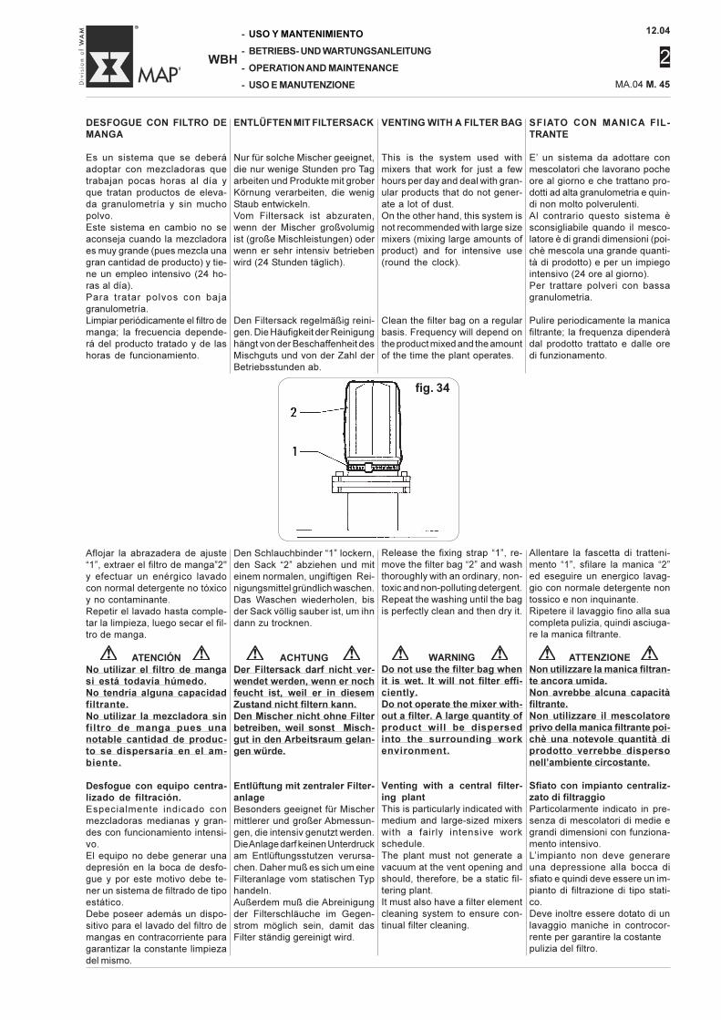
12.04
2
MA.04 M. 45
-
-
-
-
WBH
USO Y MANTENIMIENTO
BETRIEBS- UND WARTUNGSANLEITUNG
OPERATION AND MAINTENANCE
USO E MANUTENZIONE
VENTING WITH A FILTER BAG
This is the system used withmixers that work for just a fewhours per day and deal with gran-ular products that do not gener-ate a lot of dust.On the other hand, this system isnot recommended with large sizemixers (mixing large amounts ofproduct) and for intensive use(round the clock).
Clean the filter bag on a regularbasis. Frequency will depend onthe product mixed and the amountof the time the plant operates.
SFIATO CON MANICA FIL-TRANTE
E’ un sistema da adottare conmescolatori che lavorano pocheore al giorno e che trattano pro-dotti ad alta granulometria e quin-di non molto polverulenti.Al contrario questo sistema èsconsigliabile quando il mesco-latore è di grandi dimensioni (poi-chè mescola una grande quanti-tà di prodotto) e per un impiegointensivo (24 ore al giorno).Per trattare polveri con bassagranulometria.
Pulire periodicamente la manicafiltrante; la frequenza dipenderàdal prodotto trattato e dalle oredi funzionamento.
ENTLÜFTEN MIT FILTERSACK
Nur für solche Mischer geeignet,die nur wenige Stunden pro Tagarbeiten und Produkte mit groberKörnung verarbeiten, die wenigStaub entwickeln.Vom Filtersack ist abzuraten,wenn der Mischer großvolumigist (große Mischleistungen) oderwenn er sehr intensiv betriebenwird (24 Stunden täglich).
Den Filtersack regelmäßig reini-gen. Die Häufigkeit der Reinigunghängt von der Beschaffenheit desMischguts und von der Zahl derBetriebsstunden ab.
DESFOGUE CON FILTRO DEMANGA
Es un sistema que se deberáadoptar con mezcladoras quetrabajan pocas horas al día yque tratan productos de eleva-da granulometría y sin muchopolvo.Este sistema en cambio no seaconseja cuando la mezcladoraes muy grande (pues mezcla unagran cantidad de producto) y tie-ne un empleo intensivo (24 ho-ras al día).Para tratar polvos con bajagranulometría.Limpiar periódicamente el filtro demanga; la frecuencia depende-rá del producto tratado y de lashoras de funcionamiento.
Den Schlauchbinder “1” lockern,den Sack “2” abziehen und miteinem normalen, ungiftigen Rei-nigungsmittel gründlich waschen.Das Waschen wiederholen, bisder Sack völlig sauber ist, um ihndann zu trocknen.
ACHTUNGDer Filtersack darf nicht ver-wendet werden, wenn er nochfeucht ist, weil er in diesemZustand nicht filtern kann.Den Mischer nicht ohne Filterbetreiben, weil sonst Misch-gut in den Arbeitsraum gelan-gen würde.
Entlüftung mit zentraler Filter-anlageBesonders geeignet für Mischermittlerer und großer Abmessun-gen, die intensiv genutzt werden.Die Anlage darf keinen Unterdruckam Entlüftungsstutzen verursa-chen. Daher muß es sich um eineFilteranlage vom statischen Typhandeln.Außerdem muß die Abreinigungder Filterschläuche im Gegen-strom möglich sein, damit dasFilter ständig gereinigt wird.
Allentare la fascetta di tratteni-mento “1”, sfilare la manica “2”ed eseguire un energico lavag-gio con normale detergente nontossico e non inquinante.Ripetere il lavaggio fino alla suacompleta pulizia, quindi asciuga-re la manica filtrante.
ATTENZIONENon utilizzare la manica filtran-te ancora umida.Non avrebbe alcuna capacitàfiltrante.Non utilizzare il mescolatoreprivo della manica filtrante poi-chè una notevole quantità diprodotto verrebbe dispersonell’ambiente circostante.
Sfiato con impianto centraliz-zato di filtraggioParticolarmente indicato in pre-senza di mescolatori di medie egrandi dimensioni con funziona-mento intensivo.L’impianto non deve generareuna depressione alla bocca disfiato e quindi deve essere un im-pianto di filtrazione di tipo stati-co.Deve inoltre essere dotato di unlavaggio maniche in controcor-rente per garantire la costantepulizia del filtro.
Release the fixing strap “1”, re-move the filter bag “2” and washthoroughly with an ordinary, non-toxic and non-polluting detergent.Repeat the washing until the bagis perfectly clean and then dry it.
WARNINGDo not use the filter bag whenit is wet. It will not filter effi-ciently.Do not operate the mixer with-out a filter. A large quantity ofproduct will be dispersedinto the surrounding workenvironment.
Venting with a central filter-ing plantThis is particularly indicated withmedium and large-sized mixerswith a fairly intensive workschedule.The plant must not generate avacuum at the vent opening andshould, therefore, be a static fil-tering plant.It must also have a filter elementcleaning system to ensure con-tinual filter cleaning.
Aflojar la abrazadera de ajuste“1”, extraer el filtro de manga”2"y efectuar un enérgico lavadocon normal detergente no tóxicoy no contaminante.Repetir el lavado hasta comple-tar la limpieza, luego secar el fil-tro de manga.
ATENCIÓNNo utilizar el filtro de mangasi está todavía húmedo.No tendría alguna capacidadfiltrante.No utilizar la mezcladora sinfiltro de manga pues unanotable cantidad de produc-to se dispersaría en el am-biente.
Desfogue con equipo centra-lizado de filtración.Especialmente indicado conmezcladoras medianas y gran-des con funcionamiento intensi-vo.El equipo no debe generar unadepresión en la boca de desfo-gue y por este motivo debe te-ner un sistema de filtrado de tipoestático.Debe poseer además un dispo-sitivo para el lavado del filtro demangas en contracorriente paragarantizar la constante limpiezadel mismo.
fig. 34
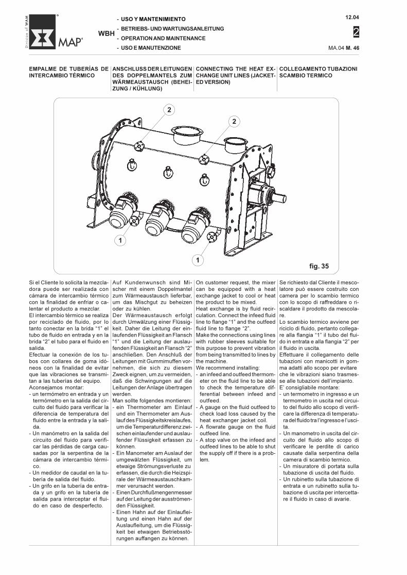
12.04
2
-
-
-
-
WBH
USO Y MANTENIMIENTO
BETRIEBS- UND WARTUNGSANLEITUNG
OPERATION AND MAINTENANCE
USO E MANUTENZIONE MA.04 M. 46
COLLEGAMENTO TUBAZIONISCAMBIO TERMICO
CONNECTING THE HEAT EX-CHANGE UNIT LINES (JACKET-ED VERSION)
ANSCHLUSS DER LEITUNGENDES DOPPELMANTELS ZUMWÄRMEAUSTAUSCH (BEHEI-ZUNG / KÜHLUNG)
EMPALME DE TUBERÍAS DEINTERCAMBIO TÉRMICO
Auf Kundenwunsch sind Mi-scher mit einem Doppelmantelzum Wärmeaustausch lieferbar,um das Mischgut zu beheizenoder zu kühlen.Der Wärmeaustausch erfolgtdurch Umwälzung einer Flüssig-keit. Daher die Leitung der ein-laufenden Flüssigkeit an Flansch“1” und die Leitung der auslau-fenden Flüssigkeit an Flansch “2”anschließen. Den Anschluß derLeitungen mit Gummimuffen vor-nehmen, die sich zu diesemZweck eignen, um zu vermeiden,daß die Schwingungen auf dieLeitungen der Anlage übertragenwerden.Man sollte folgendes montieren:- ein Thermometer am Einlauf
und ein Thermometer am Aus-lauf des Flüssigkeitskreislaufes,um die Temperaturdifferenz zwi-schen einlaufender und auslau-fender Flüssigkeit erfassen zukönnen.
- Ein Manometer am Auslauf derumgewälzten Flüssigkeit, umetwaige Strömungsverluste zuerfassen, die durch die Heizspi-rale der Wärmeaustauschkam-mer verursacht werden.
- Einen Durchflußmengenmesserauf der Leitung der ausströmen-den Flüssigkeit.
- Einen Hahn auf der Einlauflei-tung und einen Hahn auf derAuslaufleitung, um die Flüssig-keit bei etwaigen Betriebsstö-rungen auffangen zu können.
Se richiesto dal Cliente il mesco-latore può essere costruito concamera per lo scambio termicocon lo scopo di raffreddare o ri-scaldare il prodotto da mescola-re.Lo scambio termico avviene perriciclo di fluido, pertanto collega-re alla flangia “1” il tubo del flui-do in entrata e alla flangia “2” peril fluido in uscita.Effettuare il collegamento delletubazioni con manicotti in gom-ma adatti allo scopo per evitareche le vibrazioni siano trasmes-se alle tubazioni dell’impianto.E’ consigliabile montare:- un termometro in ingresso e un
termometro in uscita nel circui-to del fluido allo scopo di verifi-care la differenza di temperatu-ra del fluido tra l’ingresso e l’usci-ta.
- Un manometro in uscita del cir-cuito del fluido allo scopo diverificare le perdite di caricocausate dalla serpentina dellacamera di scambio termico.
- Un misuratore di portata sullatubazione di uscita del fluido.
- Un rubinetto sulla tubazione dientrata e un rubinetto sulla tu-bazione di uscita per intercetta-re il fluido in caso di avarie.
On customer request, the mixercan be equipped with a heatexchange jacket to cool or heatthe product to be mixed.Heat exchange is by fluid recir-culation. Connect the infeed fluidline to flange “1” and the outfeedfluid line to flange “2”.Make the connections using lineswith rubber sleeves suitable forthis purpose to prevent vibrationfrom being transmitted to lines bythe machine.We recommend installing:- an infeed and outfeed thermom-
eter on the fluid line to be ableto check the temperature dif-ferential between infeed andoutfeed.
- A gauge on the fluid outfeed tocheck load loss caused by theheat exchanger jacket coil.
- A flowrate gauge on the fluidoutfeed line.
- A stop valve on the infeed andoutfeed lines to be able to shutthe supply off if there is a prob-lem.
Si el Cliente lo solicita la mezcla-dora puede ser realizada concámara de intercambio térmicocon la finalidad de enfriar o ca-lentar el producto a mezclar.El intercambio térmico se realizapor reciclado de fluido, por lotanto conectar en la brida “1” eltubo de fluido en entrada y en labrida “2” el tubo para el fluido ensalida.Efectuar la conexión de los tu-bos con collares de goma idó-neos con la finalidad de evitarque las vibraciones se transmi-tan a las tuberías del equipo.Aconsejamos montar:- un termómetro en entrada y un
termómetro en la salida del cir-cuito del fluido para verificar ladiferencia de temperatura delfluido entre la entrada y la sali-da.
- Un manómetro en la salida delcircuito del fluido para verifi-car las pérdidas de carga cau-sadas por la serpentina de lacámara de intercambio térmi-co.
- Un medidor de caudal en la tu-bería de salida del fluido.
- Un grifo en la tubería de entra-da y un grifo en la tubería desalida para interceptar el flui-do en caso de desperfecto.
fig. 35
2
•
2
•
1
•
1
•
12.04
2
MA.04 M. 47
-
-
-
-
WBH
USO Y MANTENIMIENTO
BETRIEBS- UND WARTUNGSANLEITUNG
OPERATION AND MAINTENANCE
USO E MANUTENZIONE
Durante il primo riempimento del-la serpentina con il fluido è ne-cessario effettuare lo spurgo (congli appositi sfiatatori) delle bolled’aria eventualmente contenuteall’interno dell’impianto.Per poter completare lo spurgo ènecessario che il fluido circoli al-l’interno della serpentina per al-cune ore.Nel caso che il fluido sia in tem-perature è necessario montaresul tubo di entrata o sul tubo diuscita una valvola di sovrapres-sione tarata a 4 bar.Posizionare la valvola in modotale che l’eventuale scarico delfluido sia convogliato e non diret-to verso gli operatori.Quando il fluido di scambio su-pera la temperatura di +60°C ènecessario coibentare con mate-riale idoneo l’esterno della came-ra del mescolatore, i portelli e lecondutture di alimentazione escarico per limitare le perdite dicalore ed evitare ustioni causatedal contatto con il mescolatore.
Installazione dell'inverter
Quando c’è la necessità di va-riare il numero di giri del motore ènecessario installare un inverterutilizzando l’opzione (soft-start)poichè consente un avviamentoprogressivo e sostituisce a tutti glieffetti il giunto idrodinamico.L’installazione dell’inverter è con-sigliata nella trasmissione, tramotore elettrico e riduttore diret-ta o con cinghie.E’ sconsigliata quando la trasmis-sione è provvista di giunto idro-dinamico.
Wenn die Heizspirale zum erstenMal mit der Flüssigkeit gefüllt wird,muß man die Leitung (mit denvorhandenen Überlaufvorrichtun-gen) gründlich entlüften.Um die Entlüftung zu vervollstän-digen, muß die Flüssigkeit einpaar Stunden lang in der Heizspi-rale umlaufen.Wenn die Flüssigkeit schon dieTemperatur erreicht hat, muß aufder Einlauf- oder der Auslauflei-tung ein Überdruckventil instal-liert werden, das auf 4 bar einge-stellt wird.Das Ventil derart ausrichten, daßdie eventuell ausströmende Flüs-sigkeit nicht auf den Bedienergerichtet wird.Wenn die Flüssigkeit des Wär-meaustauschers über 60°C heißwird, muß man die Außenseiteder Mischkammer, die Inspekti-onsklappen, die Zufuhr- und dieAuslaßleitungen mit Isoliermate-rial versehen, um den Wärme-verlust zu verringern und zu ver-meiden, daß man sich beim Be-rühren des Mischers verbrennt.
Einbau eines Frequenzum-formers
Wenn eine Drehzahlverstellungdes Motors erforderlich ist, mußein FU installiert werden, wozudie Option “Soft-start” verwendetwird, weil dies ein sanftes undallmähliches Anlaufen ermöglichtund in jeder Beziehung eine hy-draulische Kupplung ersetzt.Die Installation des FU bietet sichbei direkt angebautem Flansch-getriebemotor oder bei Riemen-rieb zwischen Elektromotor undUntersetzungsgetriebe an.Nicht zum empfehlen ist ein FU,wenn das Getriebe eine hydrody-namische Kupplung hat.
When the coil is filled for the firsttime with the fluid, vent (throughthe air bleeders) any air in thecircuit.Before bleeding the air from thecircuit, run the fluid through thecoil and the circuit for a couple ofhours.If the fluid is to be heated, installa pressure release valve on theinfeed line or the outfeed line.This valve should be set for 4 bar.Locate this valve so that if itdischarges, the liquid is drainedaway and not directed towardsthe operators.When the heat exchange liquidexceeds a temperature of+60°C, the mixer chamber, hatch-es, feed and discharge pipesmust be insulated with adequatematerial to prevent heat loss andprotect those who touch the mix-er from being burnt.
Installing the inverter
When motor RPM have to bechanged, it is best to install aninverter using the soft-start op-tion as this allows a gradual startand replaces the hydraulic cou-pling.The inverter should be installed inthe drive unit between the elec-tric motor and the direct or offsetdrive unit.The inverter is not recommendedwhen the transmission has ahydraulic coupling.
La primera vez que se efectúael llenado de la serpentina con elfluido es necesario efectuar eldesfogue (con los correspon-dientes purgadores) del aireeventualmente contenido en elinterior del equipo.Para poder completar el desfo-gue es necesario que el fluidocircule en el interior de la ser-pentina durante algunas horas.Si el fluido está a temperaturaserá necesario montar en el tubode entrada o en el tubo de salidauna válvula de sobrepresión ca-librada en 4 bar.Poner la válvula de manera talde lograr una idónea orientaciónde la eventual descarga de flui-do no orientada hacia los opera-dores.Cuando el fluido de intercambiotérmico supera la temperatura de+60°C es necesario aislar conmaterial idóneo el exterior de lacámara de la mezcladora, losregistros y las tuberías de ali-mentación y descarga para limi-tar las pérdidas de calor y evitarquemaduras causadas por elcontacto con la mezcladora.
Instalación del inversor
Cuando existe la necesidad devariar el número de revol. delmotor es necesario instalar uninversor utilizando la opción(sof-start) que permite un arran-que progresivo y sustituye com-pletamente el acoplamiento hidro-dinámicoAconsejamos la instalación delinversor en la transmisión, entreel motor eléctrico y el reductor,directa o con correa.No se aconseja cuando la trans-misión posee acoplamiento hi-drodinámico.
12.04
2
-
-
-
-
WBH
USO Y MANTENIMIENTO
BETRIEBS- UND WARTUNGSANLEITUNG
OPERATION AND MAINTENANCE
USO E MANUTENZIONE MA.04 M. 48
Drukluftanschluß für die Sperr-spülung der Wellenabdichtun-gen
Die Abbildungen 18, 19 und 26zeigen das Beispiel von drei pneu-matischen Ablaufplänen.Zum normalen Lieferumfang desMischers gehören die Endlagermit ihren Wellenabdichtungsein-heiten und nur auf Wunsch dieMesserköpfe.
HinweisEndlager-Wellenabdichtungenund Messerköpfe erfordern so gutwie immer eine Luft-Sperrspü-lung.
Um die Einblasung von Luft (oderin manchen Fällen von Stickstoff)korrekt vorzunehmen, ist wie imAblaufplan in Abb. 18 ersichtlicheine kleine Schalttafel zu instal-lieren. Das Magnetventil “1” zumÖffnen der gesamten Anlage ziehtan, bevor das Mischgut in derMischkammer ankommt, damitder Durchlaß der Luft garantiertist, der andauern muß, solangedas Mischgut sich in der Misch-kammer befindet.Jeder Messerkopf verbraucht cir-ca 1 Nm3 Luft pro Stunde, wäh-rend die Endlagereinheiten jenach Größe zwischen 1-2 Nm3/hund 3-4 Nm3/h Luft pro Lager ver-brauchen.- Der Einbau von Ölern oder Luft-
schmierern längs der Luftein-blasleitung ist zu vermeiden,weil diese zur Bildung einer Kru-ste aus Mischgut und Schmier-mittel in der Mischkammer füh-ren könnte.
- Der Einbau eines Kondensat-abscheiders ist dagegen emp-fehlenswert.
- Die Leitungen sind in ihre Grö-ße im Verhältnis zum Stunden-verbrauch der beiden Endlage-reinheiten und dervorhandenenMesserköpfe auszulegen.
- Der Druck muß je nach Misch-gut eingestellt werden. Empfoh-len sind 0,5 bar.
Der exakte Druck ist vom Betrei-ber je nach dem behandelntenMischgut festzulegen.Als Faustregel gilt, daß bei Misch-gut mit gröberer Körnung derDruck niedriger gehalten werdenkann.Bei Produkten mit geringer Korn-größe, die wenig stauben, mußder Druck erhöht werden.
Allacciamento all'impiantopneumatico insufflaggio ariaai supporti
Le figure 18, 19 e 26 riportanocome titolo di esempio due sche-mi pneumatici.La normale fornitura del mesco-latore comprende i supporti e surichiesta gli agitatori.
NotaI supporti e gli agitatori richiedo-no quasi sempre un insufflaggiod’aria.
Per eseguire in modo corretto l’in-sufflaggio dell’aria (o dell’azotoquando richiesto) installare unpiccolo quadro, come da schemadi fig. 18.L’elettrovalvola “1” di apertura ditutto l’impianto, deve venire ec-citata prima che il prodotto arrivinella camera di miscelazionecosì da garantire il passaggio del-l’aria, che dovrà continuare fin-chè il prodotto resta all’interno delmescolatore.Si ricorda che ogni agitatore con-suma circa 1 Nm3 di aria all’ora,mentre i supporti consumano da1-2 Nm3/h di aria fino a 3-4 Nm3/h di aria ciascuno, dipendendodalle loro dimensioni.- E’ assolutamente da evitare l’in-
stallazione di oliatori o lubrifica-tori dell’aria lungo la linea diinsufflaggio poichè potrebberocausare la formazione di unacrosta all’interno del mescola-tore creatasi dall’impasto delprodotto con il lubrificante.
- Al contrario, si consiglia l’instal-lazione di un separatore di con-densa.
- Dimensionare i tubi in funzionedei consumi orari totali dati daidue supporti e dagli agitatoriinstallati.
- La pressione deve essere rego-lata in funzione del prodotto damiscelare; pressione consiglia-ta 0,5 bar.
Sarà l’utilizzatore che, in funzio-ne al prodotto trattato dovrà sta-bilire il corretto valore della pres-sione.Indicativamente, con prodotti adelevata granulometria la pressio-ne può essere mantenuta ai va-lori più bassi.Con prodotti a bassa granulome-trica, poco polverulenti la pressio-ne deve essere aumentata.
Hooking up the purging sys-tem of the shaft seals of theend bearing assamblies
Figs. 18, 19, 26 illustrate sometypical pneumatic layouts.Normal mixer supply includes theend bearing assemblies, whilethe chopper(s) come ass an op-tion.
NoteEnd bearing assemblies andchoppers will almost always re-quire air purging.
Install a small control panel, asshown in fig. 18, to ensure cor-rect air purging (or nitrogen if thisis required).Solenoid “1” to turn the entiresystem on, must be energizedbefore the product reaches themixing chamber so ensure thatthe air can pass through.Air delivery must continue aslong as the product is inside themixer.Bear in mind that each chopperuses around 1 Nm3 of air perhour. The end bearing assem-blies use from 1-2 Nm3 and up to3-4 Nm3 per hour each dependingon their size.- It is forbidden to install grease
nipples or lubrication pointsalong the air purging line sincethis could cause the formationof crusts inside the mixerformed from the product andthe lubricant.
- On the contrary, we recom-mend installing a condensationtap.
- Size the air line for the totalhourly consumption by the twoend bearing assemblies and thechoppers installed.
- Air pressure must be regulatedfor the product to be mixed(recommended pressure = 0.5bar).
The user, depending on the prod-uct handled, will set the correctpressure.In general terms, when the prod-uct is not fine-grain, the pressurecan be set lower.If the product is finer-grain butwith low dust content, the pres-sure must be kept a little higher.
Conexión de la instalaciónneumática soplado aire enlos soportes
Las figuras 18, 19 y 26 mues-tran como ejemplo dos esque-mas neumáticos.El suministro normal de la mez-cladora comprende los soportesy bajo pedido los agitadores.
NotaLos soportes y los agitadoresrequieren casi siempre un so-plado de aire.
Para efectuar correctamente elsoplado del aire (o del nitrógenocuando es necesario) instalar unpequeño cuadro, como se ve enel esquema de la fig. 18.La electroválvula “1” de apertu-ra de toda la instalación, tieneque ser excitada antes que elproducto llegue a la cámara demezclado para garantizar el pasodel aire, que deberá continuarmientras haya producto dentrode la mezcladora.Recordamos que cada agitadorconsume aprox 1 Nm3 de airepor hora, mientras que los so-portes consumen de 1-2 Nm3/hde aire hasta 3-4 Nm3/ h de airecada uno, en relación de sus di-mensiones.- Evitar la instalación de copas
de aceitadores o lubricadoresdel aire a lo largo de la línea desoplado pues podrían causarla formación de una costra enel interior de la mezcladora,compuesta de la mezcla delproducto con el lubricante.
- Es conveniente prever la utili-zación de un separador decondensación.
- Dimensionar los tubos en fun-ción del consumo horario totaldado por los dos soportes ylos agitadores instalados.
- La presión se debe regular enfunción del producto a mez-clar; presión aconsejada 0,5bar.
Será el usuario que, en funcióndel producto tratado deberá es-tablecer el correcto valor de lapresión.Indicativamente, con productosde elevada granulometría la pre-sión se puede mantener en losvalores más bajos.Con productos de baja granulo-metría, poco polvorosos la pre-sión se debe aumentar.
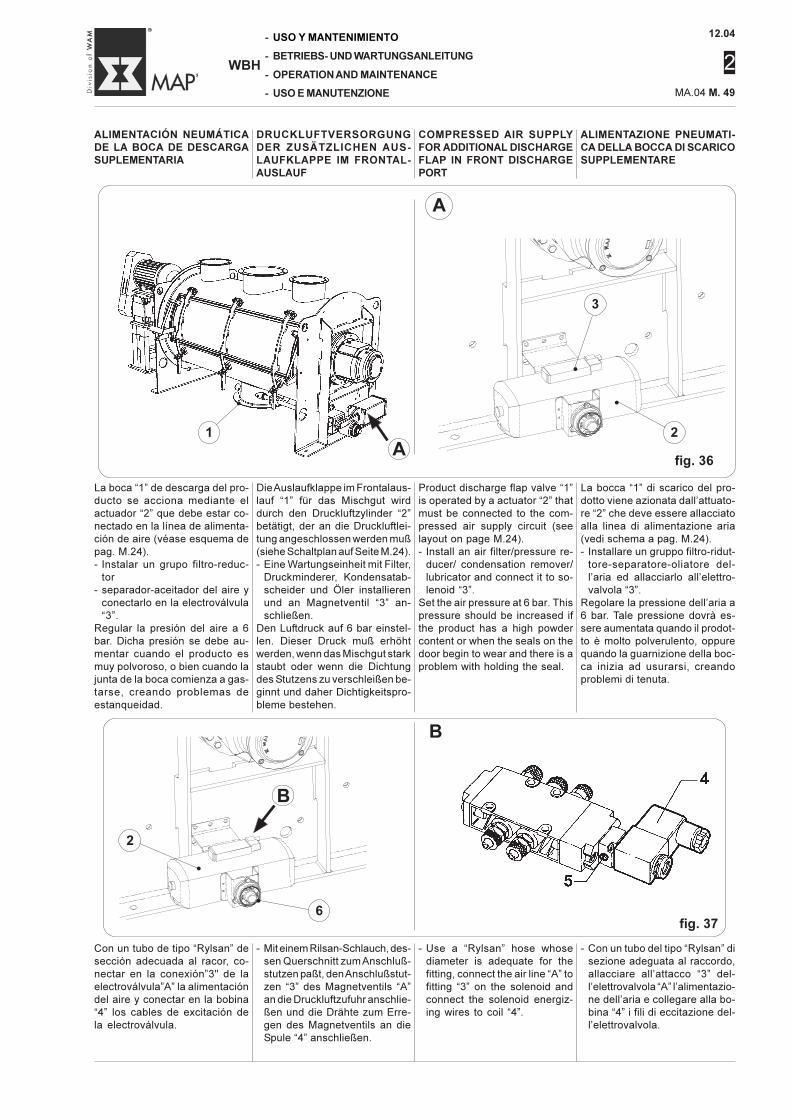
12.04
2
MA.04 M. 49
-
-
-
-
WBH
USO Y MANTENIMIENTO
BETRIEBS- UND WARTUNGSANLEITUNG
OPERATION AND MAINTENANCE
USO E MANUTENZIONE
ALIMENTAZIONE PNEUMATI-CA DELLA BOCCA DI SCARICOSUPPLEMENTARE
La boca “1” de descarga del pro-ducto se acciona mediante elactuador “2” que debe estar co-nectado en la línea de alimenta-ción de aire (véase esquema depag. M.24).- Instalar un grupo filtro-reduc-
tor- separador-aceitador del aire y
conectarlo en la electroválvula“3”.
Regular la presión del aire a 6bar. Dicha presión se debe au-mentar cuando el producto esmuy polvoroso, o bien cuando lajunta de la boca comienza a gas-tarse, creando problemas deestanqueidad.
La bocca “1” di scarico del pro-dotto viene azionata dall’attuato-re “2” che deve essere allacciatoalla linea di alimentazione aria(vedi schema a pag. M.24).- Installare un gruppo filtro-ridut-
tore-separatore-oliatore del-l’aria ed allacciarlo all’elettro-valvola “3”.
Regolare la pressione dell’aria a6 bar. Tale pressione dovrà es-sere aumentata quando il prodot-to è molto polverulento, oppurequando la guarnizione della boc-ca inizia ad usurarsi, creandoproblemi di tenuta.
ALIMENTACIÓN NEUMÁTICADE LA BOCA DE DESCARGASUPLEMENTARIA
Product discharge flap valve “1”is operated by a actuator “2” thatmust be connected to the com-pressed air supply circuit (seelayout on page M.24).- Install an air filter/pressure re-
ducer/ condensation remover/lubricator and connect it to so-lenoid “3”.
Set the air pressure at 6 bar. Thispressure should be increased ifthe product has a high powdercontent or when the seals on thedoor begin to wear and there is aproblem with holding the seal.
Die Auslaufklappe im Frontalaus-lauf “1” für das Mischgut wirddurch den Druckluftzylinder “2”betätigt, der an die Druckluftlei-tung angeschlossen werden muß(siehe Schaltplan auf Seite M.24).- Eine Wartungseinheit mit Filter,
Druckminderer, Kondensatab-scheider und Öler installierenund an Magnetventil “3” an-schließen.
Den Luftdruck auf 6 bar einstel-len. Dieser Druck muß erhöhtwerden, wenn das Mischgut starkstaubt oder wenn die Dichtungdes Stutzens zu verschleißen be-ginnt und daher Dichtigkeitspro-bleme bestehen.
COMPRESSED AIR SUPPLYFOR ADDITIONAL DISCHARGEFLAP IN FRONT DISCHARGEPORT
DRUCKLUFTVERSORGUNGDER ZUSÄTZLICHEN AUS-LAUFKLAPPE IM FRONTAL-AUSLAUF
A
B
fig. 37
Con un tubo de tipo “Rylsan” desección adecuada al racor, co-nectar en la conexión”3" de laelectroválvula”A” la alimentacióndel aire y conectar en la bobina“4” los cables de excitación dela electroválvula.
- Mit einem Rilsan-Schlauch, des-sen Querschnitt zum Anschluß-stutzen paßt, den Anschlußstut-zen “3” des Magnetventils “A”an die Druckluftzufuhr anschlie-ßen und die Drähte zum Erre-gen des Magnetventils an dieSpule “4” anschließen.
- Use a “Rylsan” hose whosediameter is adequate for thefitting, connect the air line “A” tofitting “3” on the solenoid andconnect the solenoid energiz-ing wires to coil “4”.
- Con un tubo del tipo “Rylsan” disezione adeguata al raccordo,allacciare all’attacco “3” del-l’elettrovalvola “A” l’alimentazio-ne dell’aria e collegare alla bo-bina “4” i fili di eccitazione del-l’elettrovalvola.
A
1
•
fig. 36
3
•
2
•
2
•
B
6•
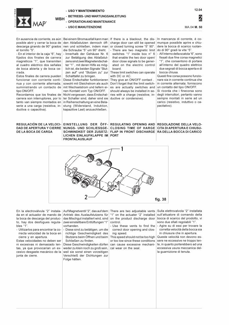
12.04
2
-
-
-
-
WBH
USO Y MANTENIMIENTO
BETRIEBS- UND WARTUNGSANLEITUNG
OPERATION AND MAINTENANCE
USO E MANUTENZIONE MA.04 M. 50
En la electroválvula “2” instala-da en el actuador de mando dela boca de descarga del produc-to, hay dos desfogues regula-bles “1”.- Utilizarlos para encontrar la co-
rrecta velocidad de la boca encierre y en apertura.
Estas velocidades no deben serni excesivas ni demasiado len-tas, ya que provocarían un ex-cesivo desgaste mecánico de lajunta de cierre.
REGOLAZIONE DELLA VELO-CITA DI APERTURA E CHIUSU-RA DELLA BOCCA DI CARICO
Sulla elettrovalvola “2” installatasull’attuatore di comando dellabocca di scarico del prodotto, visono due sfiati regolabili ”1”.- Agire su di essi per trovare la
corretta velocità della bocca siain chiusura che in apertura.
Queste velocità non devono es-sere ne eccessive ne troppo len-te, in quanto porterebbero ad unaeccessiva usura meccanica del-la guarnizione di tenuta.
REGULACIÓN DE LA VELOCI-DAD DE APERTURA Y CIERREDE LA BOCA DE CARGA
REGULATING OPENING ANDCLOSING TIME OF HARGEFLAP IN FRONT DISCHARGEPORT
EINSTELLUNG DER ÖFF-NUNGS- UND SCHLIESSGE-SCHWINDKEIT DER ZUSÄTZ-LICHEN EINLAUFKLAPPE IMFRONTALAUSLAUF
Auf Magnetventil “2”, das auf demAntrieb des Auslaufstutzens fürdas Mischgut installiert wird, sindzwei einstellbare Entlüftungen “1”vorhanden.- Diese sind zu betätigen, um die
richtige Geschwindigkeit desStutzens beim Öffnen und beimSchließen zu finden.
Diese Geschwindigkeiten dürfenweder zu klein noch zu groß sein,weil sie sonst einen vorzeitigenVerschleiß der Dichtungen zurFolge hätten.
There are two adjustable vents“1” on the actuater “2” installedon the product discharge doorcontrol.- Use these vents to find the
correct door opening and clos-ing speed.
This speed should not be too highor too low since these conditionscan cause excessive mechani-cal wear on the seal.
fig. 38
In mancanza di corrente, è co-munque possibile aprire e chiu-dere la bocca di scarico ruotan-do di 90° gradi la vite “5”.- All’interno della scatola “6”, sono
fissati due fine corsa magnetici“1”, che consentono di portareall’interno del quadro elettricodue segnali di bocca aperta e dibocca chiusa.
Questi fine corsa possono funzio-nare sia in corrente continua chein corrente alternata; fornisconoun contatto del tipo ON/OFF.Si ricorda che i finecorsa sonodegli interruttori, pertanto vannosempre montati in serie ad uncarico (resistivo, induttivo o ca-pacitativo).
Bei einem Stromausfall kann manden Ablaßstutzen dennoch öff-nen und schließen, indem mandie Schraube “5” um 90° dreht.- Innerhalb der Gehäuse Nr. 6
zur Betätigung des Ablaßstut-zens sind zwei Magnetendschal-ter “1” , mit deren Hilfe es mög-lich ist, die beiden Signale “Stut-zen auf” und “Stutzen zu” zurSchalttafel zu bringen.
Diese Endschalter funktionierensowohl mit Gleichstrom als auchmit Wechselstrom und liefern ei-nen Kontakt vom Typ ON/OFF.Nicht vergessen, dass Endschal-ter Schalter sind, daher sind siein Reihenschaltung an eine Bela-stung (Widerstand, Induktion,kapazitive Last) anzuschließen.
If there is a blackout, the dis-charge door can still be openedor closed turning screw “5” 90°.- There are two magnetic limit
switches “1” inside box n° 6that enable the two door open/door close signals to be gener-ated on the electric controlboard.
These limit switches can operatewith DC or AC.They give an ON/OFF contact .Don’t forget that the limit switch-es are actually switches andshould always be installed in se-ries with a charge (resistive, in-ductive or condensive).
En ausencia de corriente, es aúnposible abrir y cerrar la boca dedescarga girando de 90° gradosel tornillo “5”.- En el interior de la caja “6”, hayfijados dos finales de carreramagnéticos “1”, que transmitenal cuadro eléctrico dos señalesde boca abierta y de boca ce-rrada.Estos finales de carrera puedenfuncionar con corriente conti-nua y con corriente alternada;suministrando un contacto detipo ON/OFF.Recordamos que los finales decarrera son interruptores, por lotanto van siempre montados enserie a una carga (resistiva, in-ductiva o capacitiva).
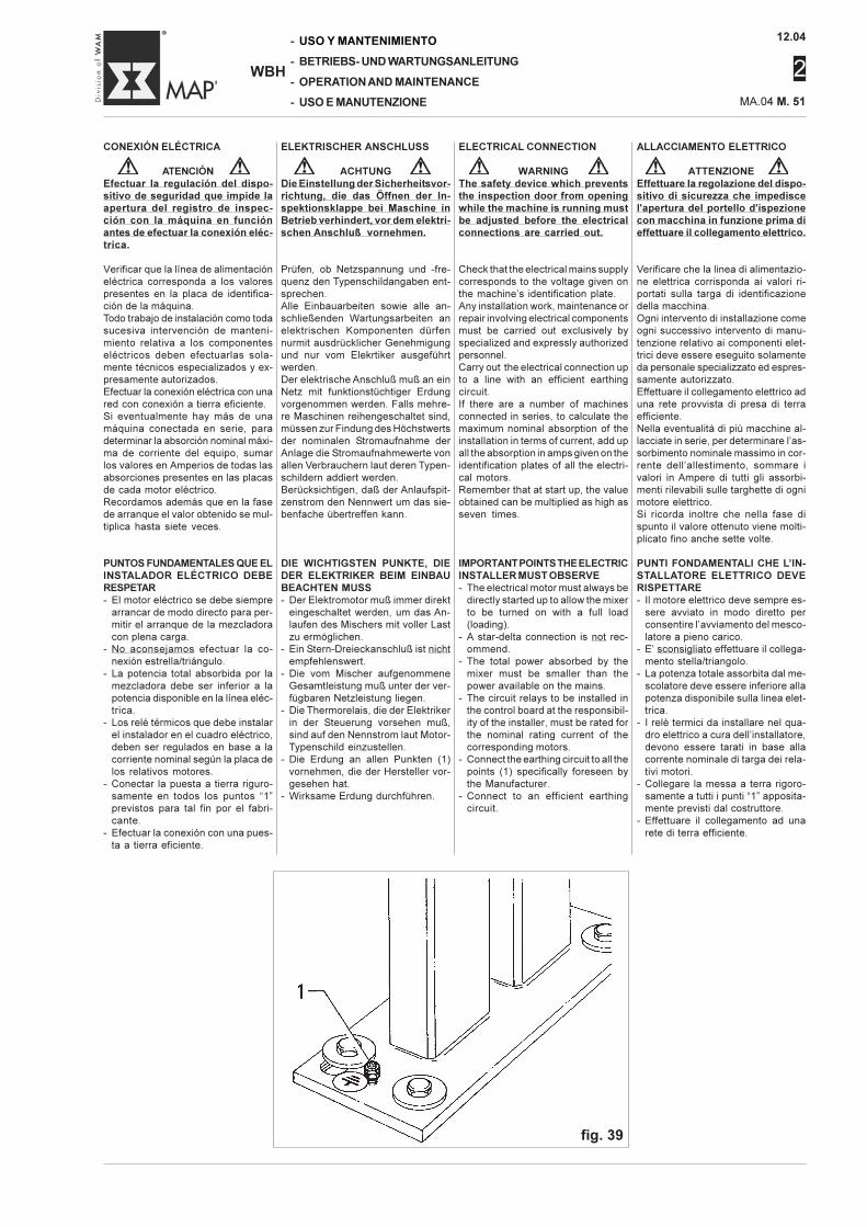
12.04
2
MA.04 M. 51
-
-
-
-
WBH
USO Y MANTENIMIENTO
BETRIEBS- UND WARTUNGSANLEITUNG
OPERATION AND MAINTENANCE
USO E MANUTENZIONE
ALLACCIAMENTO ELETTRICO
ATTENZIONEEffettuare la regolazione del dispo-sitivo di sicurezza che impediscel'apertura del portello d'ispezionecon macchina in funzione prima dieffettuare il collegamento elettrico.
Verificare che la linea di alimentazio-ne elettrica corrisponda ai valori ri-portati sulla targa di identificazionedella macchina.Ogni intervento di installazione comeogni successivo intervento di manu-tenzione relativo ai componenti elet-trici deve essere eseguito solamenteda personale specializzato ed espres-samente autorizzato.Effettuare il collegamento elettrico aduna rete provvista di presa di terraefficiente.Nella eventualità di più macchine al-lacciate in serie, per determinare l’as-sorbimento nominale massimo in cor-rente dell’allestimento, sommare ivalori in Ampere di tutti gli assorbi-menti rilevabili sulle targhette di ognimotore elettrico.Si ricorda inoltre che nella fase dispunto il valore ottenuto viene molti-plicato fino anche sette volte.
PUNTI FONDAMENTALI CHE L’IN-STALLATORE ELETTRICO DEVERISPETTARE- Il motore elettrico deve sempre es-
sere avviato in modo diretto perconsentire l’avviamento del mesco-latore a pieno carico.
- E’ sconsigliato effettuare il collega-mento stella/triangolo.
- La potenza totale assorbita dal me-scolatore deve essere inferiore allapotenza disponibile sulla linea elet-trica.
- I relè termici da installare nel qua-dro elettrico a cura dell’installatore,devono essere tarati in base allacorrente nominale di targa dei rela-tivi motori.
- Collegare la messa a terra rigoro-samente a tutti i punti “1” apposita-mente previsti dal costruttore.
- Effettuare il collegamento ad unarete di terra efficiente.
CONEXIÓN ELÉCTRICA
ATENCIÓNEfectuar la regulación del dispo-sitivo de seguridad que impide laapertura del registro de inspec-ción con la máquina en funciónantes de efectuar la conexión eléc-trica.
Verificar que la línea de alimentacióneléctrica corresponda a los valorespresentes en la placa de identifica-ción de la máquina.Todo trabajo de instalación como todasucesiva intervención de manteni-miento relativa a los componenteseléctricos deben efectuarlas sola-mente técnicos especializados y ex-presamente autorizados.Efectuar la conexión eléctrica con unared con conexión a tierra eficiente.Si eventualmente hay más de unamáquina conectada en serie, paradeterminar la absorción nominal máxi-ma de corriente del equipo, sumarlos valores en Amperios de todas lasabsorciones presentes en las placasde cada motor eléctrico.Recordamos además que en la fasede arranque el valor obtenido se mul-tiplica hasta siete veces.
PUNTOS FUNDAMENTALES QUE ELINSTALADOR ELÉCTRICO DEBERESPETAR- El motor eléctrico se debe siempre
arrancar de modo directo para per-mitir el arranque de la mezcladoracon plena carga.
- No aconsejamos efectuar la co-nexión estrella/triángulo.
- La potencia total absorbida por lamezcladora debe ser inferior a lapotencia disponible en la línea eléc-trica.
- Los relé térmicos que debe instalarel instalador en el cuadro eléctrico,deben ser regulados en base a lacorriente nominal según la placa delos relativos motores.
- Conectar la puesta a tierra riguro-samente en todos los puntos “1”previstos para tal fin por el fabri-cante.
- Efectuar la conexión con una pues-ta a tierra eficiente.
ELEKTRISCHER ANSCHLUSS
ACHTUNGDie Einstellung der Sicherheitsvor-richtung, die das Öffnen der In-spektionsklappe bei Maschine inBetrieb verhindert, vor dem elektri-schen Anschluß vornehmen.
Prüfen, ob Netzspannung und -fre-quenz den Typenschildangaben ent-sprechen.Alle Einbauarbeiten sowie alle an-schließenden Wartungsarbeiten anelektrischen Komponenten dürfennurmit ausdrücklicher Genehmigungund nur vom Elekrtiker ausgeführtwerden.Der elektrische Anschluß muß an einNetz mit funktionstüchtiger Erdungvorgenommen werden. Falls mehre-re Maschinen reihengeschaltet sind,müssen zur Findung des Höchstwertsder nominalen Stromaufnahme derAnlage die Stromaufnahmewerte vonallen Verbrauchern laut deren Typen-schildern addiert werden.Berücksichtigen, daß der Anlaufspit-zenstrom den Nennwert um das sie-benfache übertreffen kann.
DIE WICHTIGSTEN PUNKTE, DIEDER ELEKTRIKER BEIM EINBAUBEACHTEN MUSS- Der Elektromotor muß immer direkt
eingeschaltet werden, um das An-laufen des Mischers mit voller Lastzu ermöglichen.
- Ein Stern-Dreieckanschluß ist nichtempfehlenswert.
- Die vom Mischer aufgenommeneGesamtleistung muß unter der ver-fügbaren Netzleistung liegen.
- Die Thermorelais, die der Elektrikerin der Steuerung vorsehen muß,sind auf den Nennstrom laut Motor-Typenschild einzustellen.
- Die Erdung an allen Punkten (1)vornehmen, die der Hersteller vor-gesehen hat.
- Wirksame Erdung durchführen.
ELECTRICAL CONNECTION
WARNINGThe safety device which preventsthe inspection door from openingwhile the machine is running mustbe adjusted before the electricalconnections are carried out.
Check that the electrical mains supplycorresponds to the voltage given onthe machine’s identification plate.Any installation work, maintenance orrepair involving electrical componentsmust be carried out exclusively byspecialized and expressly authorizedpersonnel.Carry out the electrical connection upto a line with an efficient earthingcircuit.If there are a number of machinesconnected in series, to calculate themaximum nominal absorption of theinstallation in terms of current, add upall the absorption in amps given on theidentification plates of all the electri-cal motors.Remember that at start up, the valueobtained can be multiplied as high asseven times.
IMPORTANT POINTS THE ELECTRICINSTALLER MUST OBSERVE- The electrical motor must always be
directly started up to allow the mixerto be turned on with a full load(loading).
- A star-delta connection is not rec-ommend.
- The total power absorbed by themixer must be smaller than thepower available on the mains.
- The circuit relays to be installed inthe control board at the responsibil-ity of the installer, must be rated forthe nominal rating current of thecorresponding motors.
- Connect the earthing circuit to all thepoints (1) specifically foreseen bythe Manufacturer.
- Connect to an efficient earthingcircuit.
fig. 39
12.04
2
-
-
-
-
WBH
USO Y MANTENIMIENTO
BETRIEBS- UND WARTUNGSANLEITUNG
OPERATION AND MAINTENANCE
USO E MANUTENZIONE MA.04 M. 52
COMANDI
Informazioni generali
Generalmente i mescolatori nonvengono corredati del pannello dicomando, ma sono integrati nelquadro generale di gestione del-l’impianto di cui il mescolatore faparte.Sarà compito dell’impiantista odell’utilizzatore effettuare tale in-tegrazione e provvedere ad in-stallare un interruttore generaleper interrompere l’alimentazioneelettrica al mescolatore.Tale interruttore dovrà esseremunito di chiave di sicurezzacontro la rotazione accidentaledell’interruttore stesso.
NotaNel caso che il mescolatore siacorredato del quadro elettrico,vedere i collegamenti e i relativicomandi nel manuale elettricoallegato.
MANDOS
Informaciones generales
Generalmente las mezcladorasno presentan un tablero de man-dos, sino que los mandos estánintegrados en el cuadro generalde control del equipo del cual lamezcladora forma parte.El encargado de la instalación oel usuario deberán efectuar di-cha integración e instalar un in-terruptor general para interrum-pir la alimentación eléctrica conel mezclador.Dicho interruptor debe poseer lla-ve de seguridad contra la rota-ción accidental del interruptormismo.
NotaSi la mezcladora cuenta con elcuadro eléctrico, véanse las co-nexiones y relativos mandos enel manual eléctrico anexo.
CONTROLS
General information
Normally, the mixers are not sup-plied with a control panel, but itscontrols are included in the mainelectric control panel that runsthe entire plant of which the mix-er is a part.It is the responsibility of the in-staller or user to add on thiscomponent and install a mainswitch that will cut off the elec-trical power supplied to the mix-er.This switch must have a safetykeylock to prevent it from beingturned on by accident.
NoteIf the mixer has its own controlpanel, refer to the connectionsand descriptions of the controlsin the enclosed electric manual.
STEUERUNG
Allgemeine Informationen
Die Mischer werden in der Regelnicht mit einer eigenen Steue-rung geliefert, sondern in die An-lagensteuerung integriert.Es ist Aufgabe des Elektromon-teurs oder des Bedieners, dieseIntegration vorzunehmen und denEinbau eines Hauptschalters zurUnterbrechung der Stromzufuhrzum Mischer vorzusehen.Dieser Hauptschalter muß wie-derum mit einem Sicherheits-schalter versehen sein, der eineversehentliche Schalterbedie-nung verhindert.
HinweisWenn der Mischer mit einer eige-nen Schalttafel versehen wird,sind die Anschlüsse und die ent-sprechenden Bedienungsvorrich-tungen im beiliegenden Techni-schen Handbuch zu beachten.
12.04
2
MA.04 M. 53
-
-
-
-
WBH
USO Y MANTENIMIENTO
BETRIEBS- UND WARTUNGSANLEITUNG
OPERATION AND MAINTENANCE
USO E MANUTENZIONE
ARRANQUE Y PARADA
Como efectuar el primer arran-queAntes de comenzar a utilizar lamáquina, efectuar siempre unprimer arranque en vacío, efec-tuando todos los controles descri-tos a continuación:- Verificar que la cámara de mez-
clado no contenga cuerpos ex-traños como dispositivos de blo-queo o herramientas.
- Verificar la conexión de todoslos componentes eléctricos, in-cluso los dispositivos de seguri-dad.
- Verificar la correcta instalacióndel dispositivo bloqueo puertas(véase pag. M.43) - Efectuar lalubricación de cada engrasadorcomo se indica en la pag. M.78.La operación de engrasado ylubricación es necesaria en elcaso de prolongada inactividadde la máquina.
- Verificar la presencia de aceiteen el reductor (véase el relativomanual de Uso y Mantenimien-to).
- Verificar la presencia de aceiteen el acoplamientohidrodinámico (véase el relati-vo manual de Uso y Manteni-miento).
- Verificar la correcta regulaciónde las empaquetaduras (véasepár. M.68).
- Verificar el correcto sentido derotación del motor de la mez-cladora que debe concordar conel sentido indicado por la fle-cha aplicada en la mezcladora(véase fig 3 de pag.M.11).
- Verificar que la toma de mues-tras (si está montada) se encuen-tre cerrada (véase pag. M.82).
- Considerando las altas poten-cias instaladas, arrancar el mo-tor con un impulso del botón demando; si no hay obstruccionesen los componentes en movi-miento dar definitivamente ten-sión a la motorización de lamezcladora.
- Mantener la máquina (en va-cío) en marcha por lo menos unahora con la finalidad de verifi-car eventualessobrecalentamientos, vibracio-nes y rumores anómalos.Después de haber controladoque:
- la temperatura de los soportes yde las juntas no supere los 45-50° C;
- que no haya contactos de losútiles contra la pared de la cá-mara de mezclado; la máquinapuede comenzar a trabajar.
NotaSi la mezcladora posee agitado-res, antes de arrancar la mez-cladora es necesario arrancarlos agitadores (véase manual de“Uso y Mantenimiento” Agitador).
AVVIAMENTO E ARRESTO
Come eseguire il primo avvia-mentoPrima di iniziare l’impiego della
macchina, seguire sempre un pri-
mo avviamento a vuoto, eseguen-
do tutti i controlli di seguito de-
scritti:
- verificare che la camera di mi-
scelazione non contenga corpi
estranei come dispositivi di bloc-
caggio o attrezzi.
- Verificare il collegamento di tutti
i componenti elettrici, compresi
i dispositivi di sicurezza.
- Verificare la corretta installazio-
ne del dispositivo bloccaporta
(vedi pag. M.43)
- Procedere alla lubrificazione di
ogni ingrassatore come indicato
a pag. M.78.
L’operazione di ingrassaggio e lu-
brificazione è necessaria nel caso
di lunga inattività della macchi-
na.
- Verificare la presenza dell’olio
nel riduttore (vedi il relativo ma-
nuale di Uso e Manutenzione).
- Verificare la presenza di olio nel
giunto idrodinamico (vedi il rela-
tivo manuale di Uso e Manuten-
zione).
- Verificare la corretta registrazio-
ne delle baderne (vedi par. M.68).
- Verificare il corretto senso di ro-
tazione del motore del mescola-
tore che deve essere concorde
con il senso indicato dalla freccia
applicata sul mescolatore (vedi
fig 3 a pag.M.11).
- Verificare che il prelievo cam-
pioni (se montato) sia chiuso (vedi
pag. M.82).
- Considerando le alte potenze
installate avviare il motore con
un impulso del pulsante di co-
mando; se non ci sono impedi-
menti agli organi in movimento
dare definitivamente tensione
alla motorizzazione del mesco-
latore.
- Mantenere la macchina (a vuo-
to) in movimento per almeno
un’ora allo scopo di verificare
eventuali surriscaldamenti, vi-
brazioni e rumori anomali.
Dopo aver controllato che:
- la temperatura dei supporti e
delle tenute non superi i 45-50°
C;
- che non ci siano contatti degli
utensili contro la parete della
camera di mescolazione; la mac-
china può iniziare a lavorare.
NotaNel caso che il mescolatore sia
provvisto di agitatori, prima di av-
viare il mescolatore è necessario
avviare gli agitatori (vedi manua-
le di “Uso e Manutenzione” Agi-
tatore).
STARTING AND STOPPING
How to start the mixer for the firsttimeBefore starting to use the mixer,
always start it the first time under
no load conditions making all the
checks described below:
- check that there are no foreign
bodies in the mixing chamber
such as packing stops, tools, etc.
- Check all electric connections
including those for the safety
devices.
- Check to ensure that the in-spection hatch is installed cor-rectly (see page M.43)
- Lubricate all grease nipples as
described on page M.78.
Greasing and lubricating should
always be done when the ma-
chine has been inactive for a long
time.
- Check to make sure there is oil in
the gear unit (refer to the Oper-
ating and Maintenance Manu-
al).
- Check to be sure the hydraulic
coupling is filled with oil (refer to
the Operating and Maintenance
Manual).
- Check to be sure the packings
are correctly adjusted (see page
M.68).
- Check to be certain the mixer
motor turns in the correct direc-
tion. This should be in the direc-
tion shown by the arrow on the
mixer (see fig. 3 on page M.11).
- Check to be certain the sample
draw (if installed) is closed (see
pag M.82).
- Bearing in mind the high rating
installed, start the motor with a
pulse from the start button. If the
moving parts meet no obstacle
(they begin to turn), switch the
mixer’s power supply definitive-
ly on.
- Run the machine (empty) for atleast an hour to check for anyoverheating, vibration or ab-normal noise.
Check:
- if the temperature of the end
bearing assemblies and seals is
not higher than 45-50°C;
- the tools are not touching against
the walls of the mixer.
The machine can now begin its
operation.
NoteIf the mixer has choppers installed,
before starting the mixer, start the
choppers (refer to the Chopper
Operating and Maintenance Man-
ual).
INBETRIEBNAHMEUND ABSCHALTEN
Durchführungder ErstinbetriebnahmeBevor man die Maschine in Betriebnimmt, muß sie zunächst Materialgestartet werden, wobei alle fol-genden Kontrollen auszuführensind:- Sicherstellen, daß sich in der
Mischkammer keine Fremdkörperbefinden wie z.B. Blockerungs-schuhe oder Werkzeuge.
- Sicherstellen, daß alle elektri-schen Komponenten, einschließ-lich der Sicherheitsvorrichtungenangeschlossen sind.
- Sicherstellen, dass die Türverrie-gelung korrekt installiert wordenist (siehe Seite M.43).
- Die Schmierung aller Schmier-nippel vornehmen, wie in Ab-schnitt M.78 angegeben.
Fetten und Schmieren sind erfor-derlich, wenn die Maschine länge-re Zeit nicht in Betrieb war.- Prüfen, ob Öl im Getriebe vorhan-
den ist (vgl. die entsprechendeBetriebs- und Wartungsanlei-tung).
- Prüfen, ob Öl in der hydraulischenKupplung vorhanden ist (siehe dieentsprechende Betriebs- undWartungsanleitung).
- Prüfen, ob die Stopfbuchsen rich-tig eingestellt sind (vgl. AbschnittM.68).
- Prüfen, ob die Laufrichtung derMischerwelle korrekt ist. Die Rich-tung wird durch den Pfeil auf demMischer angegeben (vgl. Abb. 3auf Seite M.11).
- Sicherstellen, daß die Vorrichtungfür die Stichprobenentnahme(falls montiert) geschlossen ist(siehe M.82).
- Angesichts der hohen installier-ten Leistungen ist der Motor miteinem Impuls der Starttaste zustarten. Wenn die sich bewegen-den Teile nicht in ihrer Bewegunggehemmt werden, kann man dieSpannungsversorgung des An-triebsmotors des Mischers end-gültig einschalten.
- Die Maschine in leerem Zustandwenigstens eine Stunde lang lau-fen lassen, um festzustellen, obetwaige Überhitzung, Schwingun-gen und Betriebsgeräusche vor-liegen
Nachdem geprüft wurde, daß:- die Temperatur der Lager und
Dichtungen nicht mehr als 45-50°C beträgt,
- die Mischwerkzeuge nicht dieWand der Mischkammer berüh-ren, kann die Maschine den Be-trieb aufnehmen.
HinweisWenn der Mischer mit Messerköp-fen ausgestattet ist, sind vor Inbe-triebnahme des Mischers die Mes-serköpfe einzuschalten (sieheHandbuch “Betrieb und Wartung”Messerköpfe).
12.04
2
-
-
-
-
WBH
USO Y MANTENIMIENTO
BETRIEBS- UND WARTUNGSANLEITUNG
OPERATION AND MAINTENANCE
USO E MANUTENZIONE MA.04 M. 54
STOPPING
To stop the machine in an emer-gency, press the emergencySTOP button on the plant’s elec-tric control panel or near the mix-er.In normal conditions, press the“STOP” button and switch thepower supply “OFF” at the mainswitch.This cuts off power supply to themachine and stops it.The “power supply on” indicatorlight will turn off.
ARRESTO
Per arrestare la macchina in si-tuazioni di emergenza, premereil pulsante a fungo collocato sulquadro elettrico dell’impianto onelle vicinanze del mescolatore.In situazioni normali, premere ilpulsante di arresto “STOP” escollegare l’interruttore generaledi alimentazione elettrica dellamacchina.In questo modo si interrompe l’ali-mentazione al motore elettricoprovocandone l’arresto e l’indica-tore luminoso di “macchina ali-mentata elettricamente” si spe-gne.
PARADA
Para parar la máquina en situa-ciones de emergencia, apretarel botón fungiforme colocado enel cuadro eléctrico de la instala-ción o cerca de la mezcladora.En situaciones normales, apre-tar el botón de parada “STOP” ydesconectar el interruptor gene-ral de alimentación eléctrica dela máquina.De este modo se interrumpe laalimentación al motor eléctricoprovocando la parada y el indi-cador luminoso de “máquina ali-mentada eléctricamente” se apa-ga.
AUSSCHALTEN
Um die Maschine in Notfällen aus-zuschalten, die Pilz-Schlagtastebetätigen, die auf der Schalttafelder Anlage oder in unmittelbarerNähe des Mischers vorhandenist.Unter normalen Bedingungendrückt man die mit der Bezeich-nung “STOP” gekennzeichneteTaste und schaltet dann mit demHauptschalter die Stromversor-gung der Maschine ab.Auf diese Weise wird die Strom-versorgung des Elektromotorsunterbrochen, der damit zum Still-stand kommt. Dann geht auch dieKontrolleuchte “Maschine span-nungsführend” aus.
12.04
2
MA.04 M. 55
-
-
-
-
WBH
USO Y MANTENIMIENTO
BETRIEBS- UND WARTUNGSANLEITUNG
OPERATION AND MAINTENANCE
USO E MANUTENZIONE
IMPIEGO
Prescrizioni
ATTENZIONEL’uso della macchina è consen-tita solamente al personale spe-cializzato.Preliminarmente l’operatoredeve sempre accertarsi che leprotezioni siano al loro posto eche i dispositivi di sicurezza sia-no presenti ed efficienti.Effettuare diverse manovre avuoto, assistiti da personaleesperto al fine di acquisire lasensibilità e le conoscenze ne-cessarie per operare in sicurez-za.
Regolazioni preliminariPer le regolazioni ed i controlli daeseguire al primo avviamento, con-sultare pag. M.53.Di seguito si riportano le indicazio-ni per un corretto utilizzo dell’im-pianto.
COME ESEGUIRE IL CARICODEL PRODOTTO
L’ottimale utilizzo del mescolatorerichiede il caricamento del prodot-to con gli utensili in rotazione. Lapartenza del mescolatore già cari-cato del prodotto, richiederebbeuna maggiore potenza della moto-rizzazione.
ESECUZIONE DELLE PRIME CA-RICHE
Eseguiti i controlli e le prove de-scritte, la macchina è pronta al pri-mo funzionamento.
- Effettuare la prima carica del me-scolatore mantenendola sul 30%della capacità massima. Non al-lontanarsi per tutta la durata dellamiscelazione per poter interveni-re prontamente ad ogni anoma-lia.
- Le cariche successive dovrannoessere aumentate gradualmenteda un valore minimo del 30% finoa raggiungere un valore pari allacarica per la quale il mescolatoreè stato acquistato. Ricordare sem-pre che non è possibile caricareil mescolatore oltre il 70% delsuo volume teorico geometrico.
- Le prime otto ore di funzionamen-to della macchina in produzione,deve essere seguita molto da vi-cino, rilevando eventuali incon-venienti che potessero eviden-ziarsi come: vibrazioni, riscalda-menti anomali ecc..
EMPLEO
Prescripciones
ATENCIÓNEl uso de la máquina está per-mitido solamente al personalespecializado.Previamente el operador debesiempre verificar que las pro-tecciones se encuentren en sulugar y que los dispositivos deseguridad se encuentren pre-sentes y eficientes.Efectuar varias maniobras envacío, con la asistencia de per-sonal experto para poder adqui-rir la sensibilidad y los conoci-mientos necesarios para traba-jar en seguridad.
Regulaciones previasPara las regulaciones y los con-troles a efectuar en el primerarranque, consultar pag. M.53.A continuación se dan las indica-ciones para el correcto uso delequipo.
COMO EFECTUAR LA CARGADEL PRODUCTO
El óptimo uso de la mezcladorarequiere la carga del producto conlos útiles en rotación.El arranque de la mezcladora yacargada con el producto, requie-re una mayor potencia de la mo-torización.
EJECUCIÓN DE LAS PRIMERASCARGAS
Una vez efectuados los controlesy las pruebas descritas, la máqui-na está lista para comenzar a fun-cionar.
- Efectuar la primera carga de lamezcladora manteniéndola enel 30% de la capacidad máxi-ma.
No alejarse durante toda la ope-ración de mezclado para poderintervenir rápidamente en cadaanomalía.
- Las cargas sucesivas se debenaumentar gradualmente de unvalor mínimo del 30% hasta al-canzar un valor igual a la cargapara la cual la mezcladora hasido comprada.
Recordar siempre que no es posi-ble cargar la mezcladora conmás del 70% de su volumen teó-rico geométrico.
- Las primeras ocho horas de fun-cionamiento de la máquina enproducción, se debe controlarde cerca, determinando even-tuales inconvenientes que po-drían surgir como: vibraciones,recalentamientos anormales,etc..
BETRIEB
Vorschriften
ACHTUNGDie Maschine darf nur durch ge-schultes Fachpersonal bedientwerden.Der Bediener muß vor jeder Inbe-triebnahme sicherstellen, daßalle Schutzvorrichtungen korrektangebracht sind und alle Sicher-heitsvorrichtungen vorhandenund funktionstüchtig sind.Den Mischer einige Male leer lau-fen lassen und sich dabei vonerfahrenem Personal Umgang mitder Maschine schulen lassen, umsich mit der Maschine vertrautzu machen und sicher mit ihrarbeiten zu können.
Vorab-EinstellungenBezüglich Einstellungen und Kon-trollen vor der ersten Inbetriebnah-me siehe Seite M.53.Nachfolgend Angaben zur korrek-ten Benutzung des Mischers.
EINFÜLLEN DES MISCHGUTS
Die optimale Verwendung des Mi-schers sieht vor, daß man dasMischgut bei laufender Mischwelleeinfüllt. Würde der Mischer näm-lich in bereits befülltem Zustand inBetrieb genommen, müßte derMotor eine stärkere Leistung alsnormal abgeben.
ERSBEFÜLLUNG
Nach Ausführung der oben be-schriebenen Kontrollen und Testsist der Mischer zur Inbetriebnahmebereit.
- Die Ersbefüllung des Mischersvornehmen, die nicht mehr als30% des maximalen Füllvolumensbetragen sollte. Der gesamteMischvorgang muß unter Beauf-sichtigung stattfinden, um bei et-waigen Störungen sofort eingrei-fen zu können.
- Bei den anschließenden Füllun-gen kann der Mischer allmählichstärker gefüllt worden, um sichvon den 30% jener Füllmenge zunähern, für die der Mischer aus-gelegt ist. Jedoch nie dabei ver-gessen, daß der Mischer nichtüber 70 % des theoretischen ge-ometrischen Volumens hinausgefüllt werden darf.
- In den ersten acht Betriebsstun-den besonders auf etwaige Stö-rungen wie Vibrationen, abnormeErwärmung usw. achten.
USING THE MACHINE
Prescriptions
WARNINGThe machine must be used ex-clusively by trained personnel.First of all, the operator mustcheck that the guards are inposition and all safety devicesare present and efficient.Carry out a number of off-loadcycles, helped by an expert op-erator, to gain the experienceand knowledge required to runthe machine.
Preliminary AdjustmentsRefer to chapter for Adjustmentsand Checks page M.53 to carry outat first start up.The following pages provide in-formation on how to use the ma-chine correctly.
HOW TO FILL WITH PRODUCT
The optimum use of the mixerrequires that the product is filledwhen the tools are in rotation.Starting the mixer filled with prod-uct would require a much morepowerful drive motor.
MAKING THE FIRST FILLS
Once the checks and tests de-scribed here have been made, themachine is ready for its first workcycle.
- Make the first mixer fill at 30% ofits maximum capacity.Do not leave the machine for theentire mixing cycle so that youcan act immediately in any emer-gency.
- The subsequent loads should begradually increased from the in-itial 30% to the full load themixer is rated at.Remember that the mixer can-not be filled beyond 70% of itstheoretic geometric volume.
- The first eight working hours ofthe machine should be super-vised carefully and all problemssuch as vibrations, abnormalheating, etc. noted and recti-fied.
12.04
2
-
-
-
-
WBH
USO Y MANTENIMIENTO
BETRIEBS- UND WARTUNGSANLEITUNG
OPERATION AND MAINTENANCE
USO E MANUTENZIONE MA.04 M. 56
Aufstellung der Maschine
Neben dem Mischer, auf der demMotor gegenüberliegenden Sei-te, muß soviel Platz freigelassenwerden, wie man für den Ausbauder Rotorwelle benötigt.Soviel Platz lassen wie es derzweieinhalbfachen Länge derMischkammer entspricht.Nach dem Einbau sind etwaigeSchadstellen mit dem mitgelie-ferten Lack auszubessern.Außerdem sicherstellen, daß dieSicherheitsvorrichtungen und dieSchutzabdeckungen unbeschä-digt sind.
Anbringung der schwingungs-dämpfenden Platten
Die schwingungsdämpfendenPlatten sind nur dann zu montie-ren, wenn die Schwingungen ander Tragestruktur des Mischersverringert werden müssen.Die schwingungsdämpfendenPlatten aus Gummi mit hoherRückprallelastizität müssen sogroß wie die Standfläche des Mi-schers sein, eine Stärke vonwenigstens 10 mm und eine Här-te von mehr als 60 shore aufwei-sen. Als Schwingungsdämpferkein Silikongummi verwenden,weil dieses auch nach Entlastungverformt bleibt.Die Benutzung schwingungs-dämpfender Platten ist nur dannzulässig, wenn ein Grundrahmenvorgesehen ist, der die Verbin-dung zwischen Antrieb und Mi-scher starr macht. In diesem Fallsind die Platten zwischen Grund-rahmen und Fundament anzuord-nen.Die Befestigungsschrauben desMischers anziehen, bis die Gum-mistärke bis auf 1 mm reduziertist. Stärkere Deformationen sindzu vermeiden, um die Elastizitätdes Gummis nicht zu stark zuverringern.Wenn Schwingungsdämpfermontiert werden, müssen alleLeitungen, an die der Mischerangeschlossen wird, mit elasti-schen Kompensatoren versehenwerden, um zu vermeiden, daßdie Schwingungen auf die Lei-tungen übertragen werden.Die Kompensatoren müssen sonah wie möglich am Mischermontiert werden, damit das Rohr-gewicht, das auf dem Mischerlastet, reduziert wird.
Piazzamento della macchina
A fianco del mescolatore, dal latoopposto alla motorizzazione, la-sciare uno spazio tale da consen-tire lo smontaggio del rotore; cal-colare uno spazio di circa duevolte e mezzo la lunghezza dellacamera di mescolazione.Effettuata l’installazione ritocca-re la macchina con la vernice for-nita in dotazione.Verificare inoltre l’integrità dei di-spositivi di sicurezza e dei carterdi protezione.
Collocazione piastre antivi-branti
Ricorrere al montaggio delle pia-stre antivibranti solamente quan-do è necessario ridurre le vibra-zioni della struttura di sostegnomescolatore.Le piastre antivibranti di gomma,con elevata memoria elastica,devono essere di dimensionepari al piano di appoggio del me-scolatore, essere di spessore noninferiore a 10 mm e di durezzasuperiore ai 60 shore.Non utilizzare come antivibrantile gomme siliconiche poichè re-stano deformate anche dopoaverle scaricate dal carico che leha schiacciate.L’uso delle piastre antivibranti èconsentito esclusivamente se èprevisto il telaio che rende rigidoil collegamento della motorizza-zione con il mescolatore e devo-no essere posizionate tra il tela-io e la fondazione.Serrare la viteria di fissaggio delmescolatore fino a ridurre lospessore della gomma di 1 mm;deformazioni maggiori sono daevitare per non ridurre eccessi-vamente l’elasticità della gomma.E’ necessario, montando gli anti-vibranti, che tutte le condutturecollegate al mescolatore sianodotate di manicotti elastici perevitare la trasmissione delle vi-brazioni alle condutture stesse.I manicotti devono essere instal-lati il più vicino possibile al me-scolatore allo scopo di ridurre ilpeso del tubo che grava sul me-scolatore.
Locating the machine
Leave enough space at the sideof the mixer opposite the sidewhere the drive is installed sothat you can dismantle the rotor.An easy way to calculate thespace needed is to leave two anda half times the length of themixing chamber.Once the machine has been in-stalled, use the paint in the kit totouch up the paintwork as need-ed.Check to be certain that the safe-ty devices and guards are com-plete, operative and in position.
Place the vibration dampingplates
Use vibration damping plates onlywhen they are needed to reducevibration in the mixer supportstructure.The rubber vibration dampingplates have a very high elasticmemory. They must be the samesize as the mixer contact foot-print, at least 10 mm thick andwith a hardness higher than 60Shore.Do not use silicone rubber for thevibration dampers since this kindof rubber remains deformed evenafter it has discharged the loadthat has crushed it.The use of vibration dampingplates is permitted only if thedesign calls for a chassis thatcouples the drive to the mixer “enbloc”. The vibrations plates mustbe installed between the chassisand the foundation.Tighten the mixer fixing hard-ware until the thickness of therubber has been reduced by1 mm.Avoid more extensive deforma-tion of the rubber since this willnegatively affect the elasticity ofthe rubber.When the vibration dampers areinstalled, all the feed lines to themixer must be fitted with flexiblesleeves to prevent vibration frombeing transmitted to the lines.These sleeves must be installedas close to the mixer as possibleto reduce the weight of the line onthe mixer.
Emplazamiento de la máqui-na
Al lado de la mezcladora, del ladoopuesto a la motorización, dejarun espacio que permita el des-montaje del rotor; calcular unespacio de aprox. dos veces ymedia la longitud de la cámarade mezclado.Una vez efectuada la instalaciónretocar la maquina con la pintu-ra suministrada de serie.Verificar además la integridad delos dispositivos de seguridad yde los carter de protección.
Colocación planchas antivi-brantes
Efectuar el montaje de las pla-cas antivibrantes solamentecuando es necesario reducir lasvibraciones de la estructura desostén de la mezcladora.Las placas antivibrantes degoma, con elevada memoria elás-tica, deben ser de dimensiónigual al plano de apoyo de lamezcladora, de espesor no in-ferior a 10 mm y de dureza su-perior a 60 shore.No utilizar como antivibrantesgomas silicónicas pues quedandeformadas aún después dehaberles quitado el peso que lasha aplastado.El uso de placas antivibrantesestá permitido exclusivamente sise ha previsto el bastidor queconfiere rigidez a la conexión dela motorización con la mezcla-dora y las mismas deben serposicionadas entre el bastidor yla cimentación.Apretar los tornillos de fijaciónde la mezcladora hasta reducirel espesor de la goma de 1 mm;deformaciones mayores se de-ben evitar para no reducir exce-sivamente la elasticidad de lagoma.Es necesario, montando los an-tivibrantes, que todas las tube-rías conectadas con la mezcla-dora posean collares elásticospara evitar la transmisión de lasvibraciones a las tuberías mis-mas.Los collares se deben instalar lomás cerca posible de la mezcla-dora con la finalidad de reducirel peso del tubo que incide so-bre la máquina.
12.04
2
MA.04 M. 57
-
-
-
-
WBH
USO Y MANTENIMIENTO
BETRIEBS- UND WARTUNGSANLEITUNG
OPERATION AND MAINTENANCE
USO E MANUTENZIONE
BLOCCO ACCIDENTALE DELMESCOLATORE
ATTENZIONEE’ pericoloso operare comple-tamente o anche solamentecon gli arti all’interno del me-scolatore. Se fosse comunquenecessario, scollegare l’ali-mentazione elettrica dall’inter-ruttore generale che deve es-sere provvisto di chiave di si-curezza contro l’avviamentoaccidentale. Questa chiavedeve essere custodita dallastessa persona che eseguel’operazione. Quindi bloccarein modo sicuro i rotori.L’operatore, per operare in si-curezza dovrà indossare indu-menti adatti allo scopo, qualirespiratori, occhiali antinfortu-nistici ecc...
In caso di fermata accidentale,dovuta ad esempio ad un arre-sto in emergenza o per una im-provvisa mancanza di corrente,se il mescolatore non è stato con-cepito per l’avviamento a pienocarico occorre:- avviare il mescolatore in ma-
nuale. Se l’albero rotore non simuove, togliere corrente senzaattendere l’intervento del relètermico installato nel quadro elet-trico principale.
- Attendere il raffreddamento delgiunto idrodinamico (se instal-lato) e ripetere nuovamente l’av-viamento.
Se persiste la condizione di bloc-co totale aprire il portello di ispe-zione, quindi togliere manual-mente il prodotto presente all’in-terno della camera di miscelazio-ne.
NotaPer aprire il portello in mancan-za di corrente vedi M.43.
Quindi rifare l’avviamento in ma-nuale, assistiti da personaleesperto.
ATTENZIONEE' vietato nel modo più assolu-to tentare di sbloccare il me-scolatore facendo ruotare gliutensili in senso contrario.
BLOQUEO ACCIDENTAL DE LAMEZCLADORA
ATENCIÓNEs peligroso operar contodo el cuerpo o incluso sólolos brazos o las piernas den-tro de la mezcladora.Si fuese de todos modosnecesario, desconectar laalimentación eléctrica delinterruptor general quedebe contar con llave de se-guridad contra el arranqueaccidental.Esta llave debe tenerla bajosu cuidado la misma perso-na que efectúa la operación.Luego bloquear de manerasegura los rotores.El operador, para operar enseguridad debe vestirsecon indumentos idóneospara tal fin, como respirado-res, gafas de protección, etc.
En caso de parada accidental,debida por ejemplo a una para-da de emergencia o un improvi-so corte de corriente, si la mez-cladora no ha sido concebidapara el arranque en plena cargaes necesario:- arrancar la mezcladora en ma-nual.Si el árbol rotor no se mueve,quitar la corriente sin esperar laintervención del relé térmico ins-talado en el cuadro eléctrico prin-cipal.- Esperar el enfriamiento delacoplamiento hidrodinámico (siestá instalado) y repetir nueva-mente el arranque.Si persiste la condición de blo-queo total abrir el registro de ins-pección y luego quitar manual-mente el producto presente enel interior de la cámara de mez-clado.
NotaPara abrir la tapa del registro enausencia de corriente véaseM.43.
Luego efectuar el arranque enmodo manual, supervisado porpersonal experto.
ATENCIÓNEstá terminantemente pro-hibido tratar de desbloquearla mezcladora haciendo gi-rar los útiles en sentido con-trario.
UNVORGESEHENES STEHEN-BLEIBEN DES MISCHERS
ACHTUNGEs ist gefährlich, sich ganz oderauch nur teilweise mit Körper-teilen in den Mischer zu bege-ben. Wenn dies aus irgendei-nem Grund erforderlich ist,Stromversorgung durch Betä-tigung des Hauptschalters ab-schalten, der mit mit einem zu-sätzlichen Sicherungsschlüs-sel gegen unbeabsichtigtesEinschalten versehen und da-mit gesichert werden muß. Die-ser Schlüssel muß sich in denHänden derselben Person be-finden, die die Arbeiten im Mi-scher durchführt. Mischwerk-zeuge der Rotorwelle mittelsBremsschuhen blockieren.Die die Arbeiten im Mischerdurchführende Person mußhierfür geeignete Schutzklei-dung tragen (z.B. Atemgerät,Sicherheitsbrille etc.).
Bei einem außerplanmäßigenStillstand des Mischers, wie bei-spielsweise nach einem Notfalloder einem Ausfall der Stromver-sorgung, sofern der Mischer nichtfür einen Start in gefülltem Zu-stand ausgelegt ist, folgenderma-ßen vorgehen:- den Mischer vor Hand starten.
Wenn die Rotorwelle sich nichtbewegt, sofort die Stromversor-gung unterbrechen, ohne abzu-warten, daß das Thermorelaisanspricht, das im Hauptschalt-schrank installiert ist.
- Abwarten, daß die hydraulischeKupplung (falls vorhanden) ab-gekühlt ist, und den Startvor-gang wiederholen.
Wenn der Zustand der vollständi-gen Blockierung sich nicht besei-tigen läßt, die Inspektionsklappeöffnen und das im Inneren derMischkammer vorhandeneMischgut von Hand entfernen.
HinweisZum Öffnen der Tür bei Strom-ausfall siehe M.43.
Dann unter Beistand durch erfah-renes Personal den Mischer er-neut von Hand starten.
ACHTUNGEs ist strngstens verboten, zuversuchen, die Blockeierungdes Mischers zu beheben, in-dem man die Rotrwelle in um-gekehrter Drehrichtung laufenläßt.
ACCIDENTAL MIXER SHUT-DOWN
WARNINGIntervening inside the mix-er, entirely or with only partsof your body, is dangerous.Should this be necessary,electrical power must be cutoff using the main switch,which must be equipped witha safety key that preventsthe mixer from accidentallystarting up. This key must bekept by the same personwho intervenes on the mix-er. In addition, the mixing toolshafts must also be secure-ly blocked by appropriatebrake shoes.To prevent personal injury,the operator must wear ap-propriate safety gear, suchas breathing masks, safetygoggles, etc.
If the mixer accidentally stopsdue to, for example, an emergen-cy or sudden power failure, andsince the mixer has not beendesigned to start up when com-pletely full, then:- If the rotor shaft does not move,
disconnect the power withoutwaiting for the circuit breakeron the main board to trip.
- Wait until the hydraulic coupling(if installed) has cooled downand repeat the starting proce-dure.
If the total shutdown conditionpersists, open the inspectionhatch and remove the productfrom inside the mixing drum man-ually.
NoteTo open the hatch when powersupply is disconnected see M.43.
Now repeat manual start up withthe assistance of an expert op-erator.
WARNINGTrying to unblock the mixerby turning the mixing toolshafts in the opposite direc-tion is strictly prohibited.
12.04
2
-
-
-
-
WBH
USO Y MANTENIMIENTO
BETRIEBS- UND WARTUNGSANLEITUNG
OPERATION AND MAINTENANCE
USO E MANUTENZIONE MA.04 M. 58
SCAMBIO TERMICO
Se il mescolatore è provvisto dicamera per lo scambio termicoassumerà la denominazione di“Mescolatore condizionatore”(nel caso che il prodotto debbaessere raffreddato) e “Mescola-tore essiccatore” (nel caso che ilprodotto debba essere riscalda-to).
Operazioni per il correttoscambio termico del "Mescola-tore-condizionatore"
ATTENZIONELa camera di scambio termicodeve operare con una pressio-ne interna di 3 bar, poiché è sta-ta collaudata con una pressio-ne di 5 bar.E’ proibito operare con unapressione superiore a 3 bar.
Per evitare di creare della con-densa all’interno della camera dimescolazione è necessario chela temperatura del fluido di raf-freddamento non sia troppo infe-riore alla temperatura del prodot-to da mescolare.Supponiamo ad esempio di ave-re:- la temperatura prodotto in en-
trata: 60°C.- La temperatura richiesta dal pro-
dotto in uscita: 30°C.- La temperatura del fluido di
scambio termico: 5°C.Con questi valori è molto proba-bile che si crei condensa all’in-terno della camera di mescolazio-ne (specialmente quando si trat-tano prodotti che hanno umiditàintrinseca elevata).Occorre pertanto aumentare latemperatura del fluido di raffred-damento da +5°C a +17÷18°C.Per lasciare inalterato il tempodel ciclo di mescolazione (o iltempo di condizionamento) oc-corre aumentare la portata delfluido di scambio in modo dacompensare l’aumento della tem-peratura del fluido di scarico.
HEAT EXCHANGE (JACKETEDMIXERS)If the mixer has a heat exchangejacket, it is called a “Mixer-Condi-tioner” if the product is to becooled or “Mixer-Drier” if the prod-uct has to be heated.
“Mixer-Conditioner” correctheat exchange operations
WARNINGThe heat exchange jacketmust operate at an internalpressure of 3 bar because ithas been tested to 5 bar.It is forbidden to operate atpressures higher than 3 bar.
To prevent condensation form-ing in the mixing chamber, thetemperature of the cooling liquidmust not be much lower than thatof the product to be mixed.Let’s suppose, for example, thatwe have:- a product infeed temperature
of 60°C.- Required product outfeed tem-
perature of 30°C.- The temperature of the heat
exchange liquid = 5°C.At these temperatures, it is likelythat condensation will be formedinside the mixing chamber (espe-cially when dealing with prod-ucts with a very high intrinsicmoisture content).The temperature of the heat ex-change fluid will have to be raisedfrom +5°C to +17 to 18°C.In order to leave the mixing cycletime unchanged (or the condi-tioning time), increase the vol-ume of heat exchange liquid tocompensate for the increase indischarge liquid temperature.
WÄRMEAUSTAUSCH (DOP-PELMANTELVERSION)Wenn der Mischer mit einem Wär-meaustausch-Doppelmantel ver-sehen ist, dann wird der Mischerals “Mischkonditionierer” bezeich-net (wenn das Mischgut abgekühltwerden muß) und als “Trocknungs-mischer” (wenn das Mischgut er-wärmt werden muß).
Maßnahmen für den korrektenWärmeaustausch im “Misch-konditionierer”
ACHTUNGDer Doppelmantel muß mit ei-nem Innendruck von 3 bar be-aufschlagt werden (erprobt bis5 bar).Es ist verboten, den Doppel-mantel mit mehr als 3 bar zubeaufschlagen.
Um das Entstehen von Kondens-wasser im Inneren der Mischkam-mer zu vermeiden, ist dafür zusorgen, daß die Temperatur derKühlflüssigkeit nicht wesentlichtiefer als die Temperatur desMischgutes liegt.Entwickeln wir folgendes Fallbei-spiel:- Temperatur des einlaufenden
Mischguts: 60°C.- Solltemperatur des auslaufen-
den Mischguts: 30°C.- Temperatur der Flüssigkeit im
Doppelmantel: 5°C.Bei diesen Werten kommt eshöchstwahrscheinlich zur Bildungvon Kondenswasser im Innerender Mischkammer (besonders indem Fall, wo das Mischgut bereitsselbst einen hohen Eigenfeuch-tegehalt hat).Daher muß die Temperatur derFlüssigkeit für den Wärmeaus-tausch von +5°C auf +17°C bis+18°C erhöht werden.Um die Dauer des Mischzyklus-ses (oder der Kühlungszeit) nichtverändern zu müssen, ist dieDurchflußmenge der Wärme-tauschflüssigkeit so zu erhöhen,daß der Temperaturanstieg derablaufenden Flüssigkeit ausge-glichen wird.
INTERCAMBIO TÉRMICO
Si la mezcladora posee cámarapara el intercambio térmico asu-mirá la denominación “Mezclado-ra acondicionadora” (si el pro-ducto debe enfriarse) y “Mez-cladora secadora” (si el productose debe calentar).
Operaciones para el correc-to intercambio térmico de la“Mezcladora- acondiciona-dora”
ATENCIÓNLa cámara de intercambiotérmico debe trabajar conuna presión interna de 3 bar,ya que ha sido ensayadapara trabajar con una presiónde 5 bar.Está prohibido operar conuna presión superior a 3 bar.
Para evitar que se cree conden-sación en el interior de la cáma-ra de mezclado es necesario quela temperatura del fluido de re-frigeración no sea demasiadoinferior a la temperatura del pro-ducto a mezclar.Supongamos por ejemplo que:- la temperatura producto en en-trada: 60°C.- La temperatura requerida por
el producto en salida: 30°C.- La temperatura del fluido de in-
tercambio térmico: 5°C.Con estos valores es muy pro-bable que se cree condensaciónen el interior de la cámara demezclado (especialmente cuan-do se tratan productos que tie-nen humedad intrínseca eleva-da).Es necesario por lo tanto aumen-tar la temperatura del fluido derefrigeración de +5°C a+17÷18°C.Para dejar inalterado el tiempodel ciclo de mezclado (o el tiem-po de acondicionamiento) esnecesario aumentar el caudal delfluido de intercambio para com-pensar el aumento de la tempe-ratura del fluido de descarga.
12.04
2
MA.04 M. 59
-
-
-
-
WBH
USO Y MANTENIMIENTO
BETRIEBS- UND WARTUNGSANLEITUNG
OPERATION AND MAINTENANCE
USO E MANUTENZIONE
Operazioni per il correttoscambio termico del “Mescola-tore-essicatore”
Il mescolatore-essicatore stan-dard è costruito per operare contemperature fino a +110°C; pertemperature superiori è necessa-rio specificarlo sull’ordine di ac-quisto.Il fluido di scambio termico puòessere di 3 tipi:- acqua calda: il fluido non supe-
ra, generalmente, la tempera-tura di +100°C.
- Vapore: il fluido è utilizzato pertemperature superiori a +100°C.
- Olio diatermico: il fluido è utiliz-zato per temperature superioria + 100°C.
ATTENZIONEUtilizzando come fluido discambio il vapore oppure l’oliodiatermico, prestare attenzionea non superare la temperaturadel fluido di +110°C poiché ilmescolatore-essicatore stan-dard non può sopportaretemperature superiori.
Il mescolatore-essicatore puòessere utilizzato per mantenerecostante o aumentare la tempe-ratura del prodotto da trattare.
Operaciones para el correc-to intercambio térmico de la“Mezcladora- secadora”
La mezcladora-secadora están-dar está realizada para operarcon temperaturas hasta +110°C;para temperaturas superiores esnecesario especificarlo en elpedido de compra.El fluido de intercambio térmicopuede ser de 3 tipos:- agua caliente: el fluido no su-pera, generalmente, la tempera-tura de +100°C.- Vapor: el fluido se utiliza para
temperaturas superiores a+100°C.
- Aceite diatérmico: el fluido seutiliza para temperaturas supe-riores a 100°C.
ATENCIÓNUtilizando como fluido de in-tercambio el vapor o bien elaceite diatérmico, prestaratención de no superar latemperatura del fluido de+110°C pues la mezcladora-secadora estándar no pue-de soportar temperaturassuperiores.
La mezcladora-secadora sepuede utilizar para mantenerconstante o aumentar la tempe-ratura del producto a tratar.
Maßnahmen für den korrektenWärmeaustausch im “Trock-nungsmischer”
Der Trocknungsmischer in derStandardausführung wurde fürBetriebstemperaturen bis zu+110°C entwickelt. Bei höherenTemperaturen muß dies im Auf-trag ausdrücklich angegeben wer-den.Man kann 3 verschiedene Typenvon Wärmeaustauschflüssigkei-ten verwenden:- Warmwasser: Die Flüssigkeit ist
nicht wärmer als +100°C.- Dampf: Dieses Medium wird für
Temperaturen über +100°C ver-wendet.
- Diathermisches Öl: Diese Flüs-sigkeit wird für Temperaturenüber +100°C verwendet.
ACHTUNGWenn man für den Wärmeaus-tauschprozeß entweder Dampfoder diathermisches Öl ver-wendet, ist darauf zu achten,daß die Temperatur von 110°Cnicht überschritten wird, weildies die Grenztemperatur ist,für die der Trocknungsmischerin der Standardausführung aus-gelegt ist.
Der Trocknungsmischer kannbenutzt werden, um die Tempe-ratur des Mischguts konstant zuhalten oder zu erhöhen.
“Mixer-Drier” correct heatexchange operations
The standard “Mixer-Drier” is de-signed to work at temperaturesup to +110°C. If higher tempera-tures have to be handled, thisshould be specified when themachine is ordered.Three types of heat exchangefluid are used:- hot water: the liquid does not
exceed +100°C.- steam: used for temperatures
above 100°C.- diathermic oil: the liquid is used
for temperatures above 100°C.
WARNINGIf steam or diathermic oil isused as the heat exchangeliquid, be careful not to ex-ceed a liquid temperature of+110°C since the standardMixer-Drier cannot handlehigher temperatures.
The Mixer-Drier can be used tomaintain the temperature of theproduct handled constant or toincrease the temperature.
12.04
2
-
-
-
-
WBH
USO Y MANTENIMIENTO
BETRIEBS- UND WARTUNGSANLEITUNG
OPERATION AND MAINTENANCE
USO E MANUTENZIONE MA.04 M. 60
ADDING ADDITIVES
WARNINGManual addition of additives-eg, through the loading hop-per, must be done with eyeand respiratory way protec-tion.The turbulence inside couldcause dangerous leakagesof powder and sometimesthis can be toxic.
To add additives, use the requi-site loading openings designedfor this.Similarly, to add liquids, use thenozzles provided precisely forthis purpose.If your mixer does not have theseoptions, contact the Manufactur-er for the modifications to themixer that may be required.
HOW TO DISCHARGE THEPRODUCT
- The products must be unloadedinto the mixing chamber withthe tools rotating.
- Shut the discharge door onlywhen the mixing chamber iscompletely empty.
- Closing the door when the prod-uct is being discharged cancause excessive strain on thedoor mechanism and causeearly wear on the seal.
AGGIUNTA DI ADDITIVI
ATTENZIONEL’aggiunta manuale di additiviad esempio attraverso una tra-moggia di carico, si deve ese-guire proteggendo gli occhi ele vie respiratorie, poiché leturbolenze interne potrebberoprovocare pericolose fuoriu-scite di polveri, a volte anchetossiche.
Per l’aggiunta di additivi, utilizza-re le apposite bocche di caricopreviste allo scopo.Analogicamente, l’additivazionedi prodotti liquidi deve essereeseguito utilizzando gli ugelli pre-ventivamente installati.Se il Vostro mescolatore non pre-vede questi accessori, contatta-re il costruttore per le eventualimodifiche che si rendessero ne-cessarie.
COME ESEGUIRE LO SCARI-CO DEL PRODOTTO
- Lo scarico del prodotto conte-nuto nella camera di miscela-zione si deve eseguire con gliutensili in rotazione.
- Richiudere la bocca di scaricosolamente quando la camera dimiscelazione è completamentevuota.
- Una chiusura durante lo scaricodel prodotto può indurre ecces-sive sollecitazioni meccanichedi leverismi della bocca ed unaprecoce usura alle guarnizioni.
ZUGABE VON ADDITIVEN
WARTUNGDie Zumischung von Additivenper Hand, beispielsweise durcheinen Beschickungstrichter,muß mit geeignetem Schutz fürdie Augen und die Atemorganeerfolgen, weil Wirbelbildung imInneren des Mischers dazu füh-ren kann, daß gefährlicherStaub austritt, der manchmalauch giftig ist.
Zur Zugabe von Additiven am be-sten die vorgesehenen Beschik-kungsstutzen verwenden.Auf analoge Weise muß die Zu-gabe flüssiger Zusätze unter Be-nutzung von Düsen erfolgen, diezuvor eingebaut wurden. Wenndiese Zubehörteile an Ihrem Mi-scher nicht vorhanden sind, wen-den Sie sich an den Hersteller,um die Änderungen durchführenzu lassen, sofern erforderlich.
WIE MAN DAS MISCHGUT AUSDER MASCHINE ENTNIMMT
- Die Austragung des Mischgu-tes, das sich in der Mischkam-mer befindet, muss bei sich dre-henden Werkzeugen erfolgen.
- Den Auslaßstutzen erst dannwieder schließen, wenn dieMischkammer ganz leergelau-fen ist.
- Wird der Auslaßstutzen ge-schlossen, während nochMischgut ausläuft, können diedabei auftretenden mechani-schen Beanspruchungen dieHebelwerke des Stutzens über-beanspruchen und zum vorzei-tigen Verschleiß der Dichtun-gen führen.
AGREGADO DE ADITIVOS
ATENCIÓNLa operación de agregarmanualmente aditivos porejemplo mediante una tolvade carga, se debe efectuarprotegiendo los ojos y lasvías respiratorias, pues lasturbulencias internas po-drían provocar peligrosassalidas de polvos, a vecestambién tóxicas.
Para agregar aditivos, utilizar lascorrespondiente bocas de car-ga previstas para tal fin.Análogamente, la aditivación deproductos líquidos se debe efec-tuar utilizando las boquillas ins-taladas para tal fin.Si su mezcladora no posee es-tos accesorios, contactar al fa-bricante para las eventualesmodificaciones que se hicierannecesarias.
COMO EFECTUAR LA CARGADEL PRODUCTO
- La descarga del producto con-tenido en la cámara de mez-clado se debe efectuar con losútiles en rotación.
- Volver a cerrar la boca de des-carga solamente cuando la cá-mara de mezclado está com-pletamente vacía.
- El cierre durante la descargadel producto puede provocarexcesivos esfuerzos mecáni-cos de los varillajes de la bocay un precoz desgaste de lasjuntas.
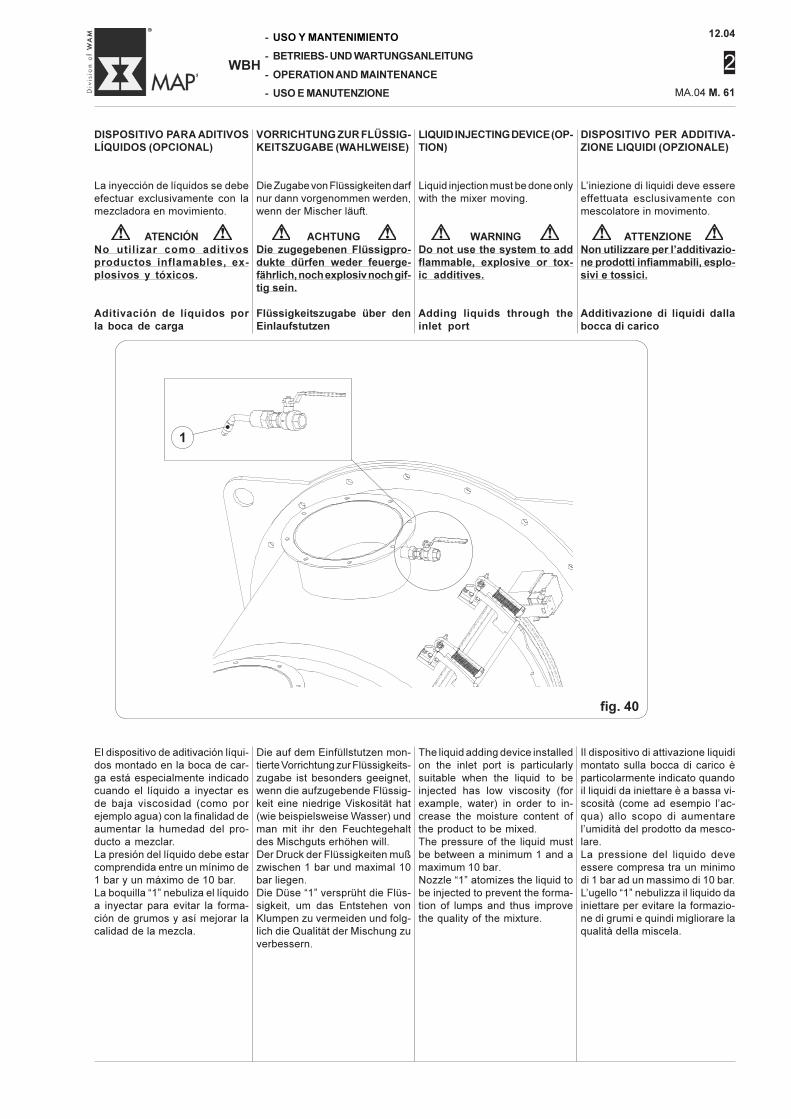
12.04
2
MA.04 M. 61
-
-
-
-
WBH
USO Y MANTENIMIENTO
BETRIEBS- UND WARTUNGSANLEITUNG
OPERATION AND MAINTENANCE
USO E MANUTENZIONE
DISPOSITIVO PARA ADITIVOSLÍQUIDOS (OPCIONAL)
La inyección de líquidos se debeefectuar exclusivamente con lamezcladora en movimiento.
ATENCIÓNNo utilizar como aditivosproductos inflamables, ex-plosivos y tóxicos.
Aditivación de líquidos porla boca de carga
DISPOSITIVO PER ADDITIVA-ZIONE LIQUIDI (OPZIONALE)
L’iniezione di liquidi deve essereeffettuata esclusivamente conmescolatore in movimento.
ATTENZIONENon utilizzare per l’additivazio-ne prodotti infiammabili, esplo-sivi e tossici.
Additivazione di liquidi dallabocca di carico
VORRICHTUNG ZUR FLÜSSIG-KEITSZUGABE (WAHLWEISE)
Die Zugabe von Flüssigkeiten darfnur dann vorgenommen werden,wenn der Mischer läuft.
ACHTUNGDie zugegebenen Flüssigpro-dukte dürfen weder feuerge-fährlich, noch explosiv noch gif-tig sein.
Flüssigkeitszugabe über denEinlaufstutzen
LIQUID INJECTING DEVICE (OP-TION)
Liquid injection must be done onlywith the mixer moving.
WARNINGDo not use the system to addflammable, explosive or tox-ic additives.
Adding liquids through theinlet port
El dispositivo de aditivación líqui-dos montado en la boca de car-ga está especialmente indicadocuando el líquido a inyectar esde baja viscosidad (como porejemplo agua) con la finalidad deaumentar la humedad del pro-ducto a mezclar.La presión del líquido debe estarcomprendida entre un mínimo de1 bar y un máximo de 10 bar.La boquilla “1” nebuliza el líquidoa inyectar para evitar la forma-ción de grumos y así mejorar lacalidad de la mezcla.
Die auf dem Einfüllstutzen mon-tierte Vorrichtung zur Flüssigkeits-zugabe ist besonders geeignet,wenn die aufzugebende Flüssig-keit eine niedrige Viskosität hat(wie beispielsweise Wasser) undman mit ihr den Feuchtegehaltdes Mischguts erhöhen will.Der Druck der Flüssigkeiten mußzwischen 1 bar und maximal 10bar liegen.Die Düse “1” versprüht die Flüs-sigkeit, um das Entstehen vonKlumpen zu vermeiden und folg-lich die Qualität der Mischung zuverbessern.
The liquid adding device installedon the inlet port is particularlysuitable when the liquid to beinjected has low viscosity (forexample, water) in order to in-crease the moisture content ofthe product to be mixed.The pressure of the liquid mustbe between a minimum 1 and amaximum 10 bar.Nozzle “1” atomizes the liquid tobe injected to prevent the forma-tion of lumps and thus improvethe quality of the mixture.
Il dispositivo di attivazione liquidimontato sulla bocca di carico èparticolarmente indicato quandoil liquidi da iniettare è a bassa vi-scosità (come ad esempio l’ac-qua) allo scopo di aumentarel’umidità del prodotto da mesco-lare.La pressione del liquido deveessere compresa tra un minimodi 1 bar ad un massimo di 10 bar.L’ugello “1” nebulizza il liquido dainiettare per evitare la formazio-ne di grumi e quindi migliorare laqualità della miscela.
fig. 40
1•
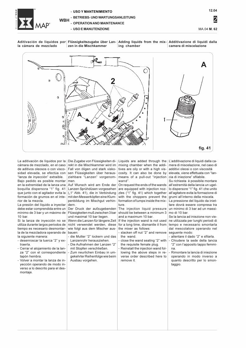
12.04
2
-
-
-
-
WBH
USO Y MANTENIMIENTO
BETRIEBS- UND WARTUNGSANLEITUNG
OPERATION AND MAINTENANCE
USO E MANUTENZIONE MA.04 M. 62
Flüssigkeitszugabe über Lan-zen in die Mischkammer
Additivazione di liquidi dallacamera di miscelazione
Aditivación de líquidos porla cámara de mezclado
Adding liquids from the mix-ing chamber
La aditivación de líquidos por lacámara de mezclado, en el casode aditivos oleosos o con visco-sidad elevada, se efectúa con“lanza de inyección” extraíble.Bajo pedido es posible montaren la extremidad de la lanza unaboquilla dispersora “1” fig. 41que junto con el agitador evita laformación de grumos en el inte-rior de la mezcla.La presión del líquido a inyectardebe estar comprendida entre unmínimo de 3 bar y un máximo de10 bar.Si la lanza de inyección no seutiliza durante largos periodos detiempo es necesario desmontar-la de la mezcladora operando dela siguiente manera:- desenroscar la tuerca “2” y ex-
traerla.- Cerrar el alojamiento de la lan-
za “2” con el correspondientetapón hembra.
- Volver a montar la lanza de in-yección operando de modo in-verso a lo descrito para el des-montaje.
Die Zugabe von Flüssigkeiten di-rekt in die Mischkammer wird imFall von öligen und stark visko-sen Flüssigkeiten über heraus-ziehbare “Lanzen” vorgenom-men.Auf Wunsch wird am Ende derLanzen Sprühdüsen vorgesehen(„1“ Abb. 41), die in Verbindungmit den Messerköpfen eine Klum-penbildung im Mischgut verhin-dern.Der Druck der aufzugebendenFlüssigkeiten muß zwischen 3 barund maximal 10 bar liegen.Wenn die Lanzen für längere Zeitnicht verwendet werden, diesewie folgt aus dem Mischer aus-bauen:- die Mutter “2” lockern und das
Lanzenrohr herausziehen.- Die Aufnahmen der Lanzen “2”
mit Stopfen verschließen.- Zum neurlichen Einbau in um-
gekehrter Reihenfolge wie beimAusbau vorgehen.
Liquids are added through themixing chamber when the addi-tives are oily or with a high vis-cosity. It can also be done bymeans of a pull-out “injectionwand”.On request the ends of the wandsare equipped with injection noz-zles (“1” fig. 41) which togetherwith the choppers prevent theformation of lumps inside the mix-ture.The injection liquid pressureshould be between a minimum 3and a maximum 10 bar.If the injection wand is not usedfor a long time, dismantle it fromthe mixer as follows:- slacken off nut “2” and remove
the wand.- close the wand seating “2” with
the requisite female plug.- Reinstall the injection wand fol-
lowing the above steps in re-verse order described here toremove it.
L’additivazione di liquidi dalla ca-mera di miscelazione, nel caso diadditivi oleosi o con viscositàelevata, viene effettuata con “lan-cia di iniezione” sfilabile.Su richiesta è possibile montareall’estremità della lancia un ugel-lo dispersore “1” fig. 41 che unitoall’agitatore evita la formazione digrumi all’interno della miscela.La pressione del liquido da iniet-tare dovrà essere compresa traun minimo di 3 bar ad un massi-mo di 10 bar.Se la lancia ad iniezione non vie-ne utilizzata per lunghi periodi ditempo e necessario smontarladal mescolatore operando nelseguente modo:- allentare il dado “2” e sfilarla.- Chiudere la sede della lancia
“2” con l’apposito tappo femmi-na.
- Rimontare la lancia di iniezioneoperando in modo inverso aquanto descritto per lo smon-taggio.
A
fig. 41
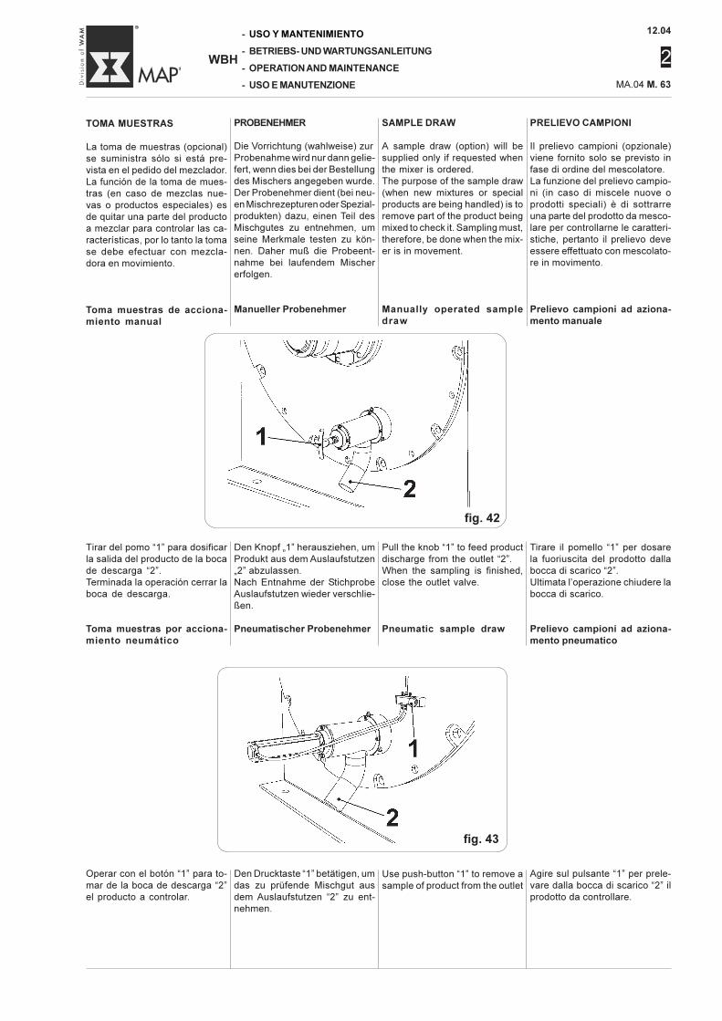
12.04
2
MA.04 M. 63
-
-
-
-
WBH
USO Y MANTENIMIENTO
BETRIEBS- UND WARTUNGSANLEITUNG
OPERATION AND MAINTENANCE
USO E MANUTENZIONE
PRELIEVO CAMPIONI
Il prelievo campioni (opzionale)viene fornito solo se previsto infase di ordine del mescolatore.La funzione del prelievo campio-ni (in caso di miscele nuove oprodotti speciali) è di sottrarreuna parte del prodotto da mesco-lare per controllarne le caratteri-stiche, pertanto il prelievo deveessere effettuato con mescolato-re in movimento.
Prelievo campioni ad aziona-mento manuale
SAMPLE DRAW
A sample draw (option) will besupplied only if requested whenthe mixer is ordered.The purpose of the sample draw(when new mixtures or specialproducts are being handled) is toremove part of the product beingmixed to check it. Sampling must,therefore, be done when the mix-er is in movement.
Manually operated sampledraw
TOMA MUESTRAS
La toma de muestras (opcional)se suministra sólo si está pre-vista en el pedido del mezclador.La función de la toma de mues-tras (en caso de mezclas nue-vas o productos especiales) esde quitar una parte del productoa mezclar para controlar las ca-racterísticas, por lo tanto la tomase debe efectuar con mezcla-dora en movimiento.
Toma muestras de acciona-miento manual
PROBENEHMER
Die Vorrichtung (wahlweise) zurProbenahme wird nur dann gelie-fert, wenn dies bei der Bestellungdes Mischers angegeben wurde.Der Probenehmer dient (bei neu-en Mischrezepturen oder Spezial-produkten) dazu, einen Teil desMischgutes zu entnehmen, umseine Merkmale testen zu kön-nen. Daher muß die Probeent-nahme bei laufendem Mischererfolgen.
Manueller Probenehmer
fig. 42
Tirar del pomo “1” para dosificarla salida del producto de la bocade descarga “2”.Terminada la operación cerrar laboca de descarga.
Toma muestras por acciona-miento neumático
Den Knopf „1” herausziehen, umProdukt aus dem Auslaufstutzen„2” abzulassen.Nach Entnahme der StichprobeAuslaufstutzen wieder verschlie-ßen.
Pneumatischer Probenehmer
Pull the knob “1” to feed productdischarge from the outlet “2”.When the sampling is finished,close the outlet valve.
Pneumatic sample draw
Tirare il pomello “1” per dosarela fuoriuscita del prodotto dallabocca di scarico “2”.Ultimata l’operazione chiudere labocca di scarico.
Prelievo campioni ad aziona-mento pneumatico
fig. 43
Agire sul pulsante “1” per prele-vare dalla bocca di scarico “2” ilprodotto da controllare.
Use push-button “1” to remove asample of product from the outlet
Operar con el botón “1” para to-mar de la boca de descarga “2”el producto a controlar.
Den Drucktaste “1” betätigen, umdas zu prüfende Mischgut ausdem Auslaufstutzen “2” zu ent-nehmen.
12.04
2
-
-
-
-
WBH
USO Y MANTENIMIENTO
BETRIEBS- UND WARTUNGSANLEITUNG
OPERATION AND MAINTENANCE
USO E MANUTENZIONE MA.04 M. 64
MANUTENZIONE
ATTENZIONEOgni intervento di manutenzio-ne di lubrificazione e di puliziadeve essere eseguito a macchi-na ferma e scollegata dell’ali-mentazione elettrica.Le operazioni di manutenzionedevono essere effettuate da tec-nici specializzati e autorizzati.Sollevare e maneggiare tutti iparticolari pesanti con un mez-zo di sollevamento di capacitàadatta.Assicurarsi che i gruppi od iparticolari siano sostenuti daimbracature e ganci appropria-ti.Accertarsi che non ci siano per-sone in prossimità del carico dasollevare.
Si ricorda che una precisa e pe-
riodica manutenzione ed un uso
corretto sono la premessa indi-
spensabile per garantire un eleva-
to rendimento della macchina.
Per assicurare un suo costante e
regolare funzionamento ed evita-
re il decadimento della garanzia,
ogni eventuale sostituzione di
componenti deve essere effettua-
ta esclusivamente con ricambi ori-
ginali.
Controlli effettuati nei nostristabilimentiLa macchina in Vostro possesso
ha subito presso i nostri stabili-
menti un reale collaudo di funzio-
namento, così da garantire la cor-
retta messa in esercizio.
In particolare i controlli compiuti
dal costruttore sono i seguenti:
Prima della messa in funzionedella macchina:- controllo della tensione di fun-
zionamento della macchina.
Deve corrispondere al valore ri-
chiesto al momento dell’acqui-
sto.
- Controllo del numero di matrico-
la.
- Controllo presenza di tutte le tar-
ghette.
- Controllo dei dispositivi di sicu-
rezza.
- Controllo e serraggio di tutta la
viteria.
- Controllo allineamento della tra-
smissione.
- Controllo dimensionale.
- Controllo verniciatura e tratta-
mento antiruggine.
- Controllo imballaggio.
Con macchina funzionante:- Controllo generale di funziona-
mento a vuoto per circa 1 ora.
Questi controlli hanno lo scopo
di mettere in evidenza eventuali
anomalie.
MANTENIMIENTO
ATENCIÓNTodo trabajo de mantenimiento,lubricación y limpieza debe efec-tuarse con la máquina parada ydesconectada de la alimenta-ción eléctrica.Las operaciones de manteni-miento deben estar a cargo detécnicos especializados y auto-rizados.Elevar y manipular todas laspartes pesadas con un mediode elevación y capacidad idó-neo.Cerciorarse que los grupos o laspiezas estén soportados poreslingas o ganchos idóneos.Cerciorarse que no haya perso-nas cerca de la carga a elevar.
Se recuerda que un manteni-
miento preciso y periódico y un
uso correcto constituyen las pre-
misas indispensables para garan-
tizar un elevado rendimiento de
la máquina.
Para garantizar el funcionamien-
to constante y regular y evitar que
se pierdan los derechos para las
sustituciones en garantía, utilizar
siempre repuestos originales para
sustituir los componentes..
Controles efectuados en nues-tros establecimientosLa máquina en su poder ha sido
sometida en nuestros estableci-
mientos a una real prueba de fun-
cionamiento, para garantizar la
correcta puesta e servicio.
En particular el fabricante ha efec-
tuado los siguientes controles:
Antes de la puesta en serviciode la máquina:- control de la tensión de funcio-
namiento de la máquina.
Debe corresponder al valor pe-
dido en el momento de la com-
pra.
- Control del número de matrícu-
la.
- Control de la presencia de to-
das las placas
- Control de los dispositivos de
seguridad.
- Control y ajuste de todos los
bulones, tornillos y tuercas
- Control alineación de la trans-
misión.
- Control dimensional.
- Control barnizado y tratamien-
to antióxido.
- Control embalaje.
Con máquina en función:- Control general de funciona-
miento en vacío durante aprox
1 hora.
Estos controles tienen la finali-
dad de poner en evidencia even-
tuales anomalías.
MAINTENANCE
WARNINGAny maintenance work, lubrica-tion or cleaning must be carriedout with the machine stoppedand disconnected from the elec-tric and compressed air supplysources.Maintenance and service workmust only be done by special-ized and authorized service en-gineers.All heavy parts must be hoistedand handled using approved lift-ing equipment with adequatecarrying capacity.Ensure that sections or parts ofthe machine are held by appro-priate slings and hooks.Check to ensure there are nobystanders in the range of theload to be lifted.
Remember that careful mainte-
nance in compliance with the rec-
ommended schedule and correct
use of the machine are essential
conditions to guarantee high ma-
chine performance.
In order to ensure constant and
regular operation of the machine
and to avoid cancellation of the
warranty, any part replacement
must be made exclusively with
original spares.
Inspections performed at the fac-toryYour machine has been fully test-
ed in our factory to ensure it will
work correctly when you start it up.
In particular, the following checks
were made by the Manufacturer:
Tests made before the machineis actually operated:- the operating voltage corre-
sponds to that requested with
the order.
- The serial number is checked.
- Check to make sure all tag plates
and stickers are in place.
- Checking the safety mecha-
nisms.
- Check the tightening of all nuts
and bolts.
- Drive alignment is checked.
- Dimensional check.
- The paintwork and rust treat-
ment is checked.
- The packing is checked.
Tests made with the machinerunning- General functional tests working
under no load conditions for
about an hour.
These tests and checks are de-
signed to highlight any problems
or defects.
WARTUNGSANLEITUNG
ACHTUNGZum Reinigen und Schmierenmuß die Maschine stillstehenund die Hauptstromversorgungunbedingt abgeschaltet sein.Die Wartungsarbeiten müssenvon geschultem Fachpersonalmit entsprechender Genehmi-gung durchgeführt werden.Alle schweren Teile mit geprüf-tem Hebezeug mit geeigneterTragfähigkeit heben und han-deln.Sicherstellen, daß die Baugrup-pen oder Einzelteile mit geeig-neten Anschlagmitteln und Last-haken gehalten werden.Sicherstellen, daß sich in derNähe der zu hebenden Last kei-ne Personen aufhalten.
Eine genau durchgeführte und re-
gelmäßige Wartung sowie die kor-
rekte Bedienung sind Vorausset-
zungen für eine hohe Leistung der
Maschine.
Um den konstanten und ordnungs-
gemäßen Betrieb der Maschine
gewährleisten un die Garantie auf-
rechterhalten zu können, dürfen
zum Austausch von Teilen aus-
schließlich Original-Ersatzteile
verwendet werden.
Kontrollen im HerstellerwerkDie von Ihnen erworbene Maschi-
ne wurde im Herstellerwerk einer
einer gründlichen Abnahmeprü-
fung unterzogen, damit ihre kor-
rekte Inbetriebnahme gewährlei-
stet ist.
Der Hersteller hat insbesondere
folgende Kontrollen durchgeführt:
Vor der Inbetriebnahme derMaschine:- Kontrolle der Betriebsspannung
der Maschine. Diese muß dem
Wert entsprechen, der bei der
Bestellung angegeben wurde.
- Kontrolle der Serien-Nr.
- Kontrolle auf das Vorhandensein
aller Schilder.
- Kontrolle der Sicherheitsvorrich-
tungen.
- Kontrolle aller Schrauben auf
festen Sitz.
- Kontrolle der Ausrichtung des
Antriebs
- Kontrolle der Abmessungen.
- Kontrolle der Lackierung und
Rostschutzbehandlung.
- Kontrolle der Verpackung.
Mit laufender Maschine:- Allgemeine Kontrolle bei leer-
laufender Maschine mit einstün-
diger Dauer.
Diese Kontrollen haben den
Zweck, etwaige Unregelmäßigkei-
ten zu erkennen.
12.04
2
MA.04 M. 65
-
-
-
-
WBH
USO Y MANTENIMIENTO
BETRIEBS- UND WARTUNGSANLEITUNG
OPERATION AND MAINTENANCE
USO E MANUTENZIONE
CONTROLLI E VERIFICHE DA EF-FETTUARE ALL’INSTALLAZIONEPRESSO L’UTILIZZATORE
Per assicurarsi che la macchina du-rante il trasporto e l’installazione nonabbia subito danni, eseguire con scru-polo i seguenti controlli.
Prima dell’avviamento- Verifica della corretta tensione di
alimentazione. Confrontare i valoridi targa della macchina.
- Verifica del dispositivo di bloccag-gio bloccaporta (vedi par. M.43).
- Verificare la presenza e l’integritàdelle targhe di pericolo e di avverten-za.
- Verificare il non bloccaggio dei pre-mibaderna per tenute supportid’estremità. Devono essere tensio-nati manualmente senza l’ausilio dichiavi.
- Verificare l’allineamento della moto-rizzazione al rotore del mescolatore.
Con macchina in funzione
- Controllare l’efficienza e l’integrità ditutte le protezioni e dei dispositivi disicurezza. Il trasporto o l’installazionepotrebbero averli danneggiati o sre-golati.
- Controllare il corretto tensionamen-to della baderna (vedi par. M.59).
- Controllare la temperatura di regimedei vari componenti. Non devonoriscaldarsi in modo eccessivo.
- Lasciare funzionare a vuoto la mac-china per almeno 1 ora senza mate-riale all’interno della camera di mi-scelazione per verificare il correttofunzionamento di ogni componente.
Si ricorda come il mescolatore possalavorare su di una gamma vastissi-ma di prodotti.Questo comporta una diversa rapidi-tà nell’usura dei materiali di consu-mo.I tempi di intervento di manutenzioneconsigliati sono quindi suscettibili dimodifiche.E’ sempre preferibile programmareperiodicamente gli interventi anzichèdover intervenire in condizioni di emer-genza. Questo sia per una ragioneeconomica che di comodità di inter-vento, così da eliminare potenziali ar-resti durante i periodi di piena produ-zione.Nello smontaggio di tale macchina èdecisamente preponderante il costodella mano d’opera rispetto al costodel materiale sostituito. Eventualmen-te, contattare i tecnici della ditta co-struttrice e programmare interventicombinati con i Vs tecnici per effet-tuare la sostituzione di tutto il mate-riale di usura esistente sul mescola-tore.
KONTROLLEN UND PRÜFUNGENBEIM EINBAU IM WERK DES BE-TREIBERS
Um sicherzustellen, daß die Maschinebei beim Transport und beim Einbaukeinen Schaden erlitten hat, sind fol-gende Kontrollen sorgfältig durchzu-führen.
Vor der Inbetriebnahme- Prüfen, ob die Speisespannung kor-
rekt ist. Mit den Werten auf demTypenschild der Maschine verglei-chen.
- Überprüfung der Türverriegelungs-vorrichtung (siehe Par. M.43).
- Prüfen, ob alle Warn- und Gefahren-schilder vorhanden und gut lesbarsind.
- Sicherstellen, dass die Stopfbuch-senbrillen für die Endlagereinheitennicht blockiert sind. Sie müssen vonHand, ohne Verwendung von Werk-zeugschlüsseln angezogen werden.
- Die Ausrichtung des Antriebs zurRotorwelle prüfen.
Bei laufender Maschine
- Die Unversehrtheit und Funktions-tüchtigkeit aller Schutz- und Sicher-heitsvorrichtungen prüfen. DurchTransport oder Einbau könnte siesich verstellt haben.
- Sicherstellen, daß die Stopfbuchsekorrekt angezogen ist (siehe M.59).
- Die Betriebstemperatur der ver-schiedenen Komponenten prüfen.Diese dürfen sich nicht zu starkerwärmen.
- Die Maschine mindestens eine Stun-de ohne Mischgut in der Mischkam-mer laufen lassen und dabei jedesMaschinenteil auf korrekten Betriebprüfen.
Der Mischer kann mit einer Vielzahlvon Produkten arbeiten.Das bedeutet unterschiedliche Ver-schleißzeiten der Verschleiß-teile.Die empfohlenen Wartungsintervallemüssen daher den jeweiligen Gege-benheiten angepaßt werden.Die Wartungsarbeiten sollten in regel-mäßigen Abständen geplant werden,um anschließend nicht unter Zeit-druck eingreifen zu müssen. Dadurchwerden mögliche Ausfallzeiten wäh-rend der regulären Produktion vermie-den.Bei der Demontage der Maschineüberwiegen die Lohnkosten entschie-den gegenüber den Kosten für die zuersetzenden Teile. Wenden Sie sich anden Hersteller und planen zusammenmit ihm den Austausch aller Ver-schleißteile des Mischers.
CONTROLES Y PRUEBAS A EFEC-TUAR DURANTE LA INSTALACIÓNEN LA PLANTA DEL USUARIO
Para verificar que la máquina duran-te el transporte y la instalación nohaya sufrido daños, efectuar conescrúpulo los siguientes controles.
Antes del arranque- Verificar la correcta tensión de ali-
mentación. Controlar los valores dela placa de identificación de la má-quina.
- Controlar el dispositivo de bloqueopuertas (véase parr. M.43).
- Verificar la presencia y la integri-dad de las placas de peligro y deadvertencia.
- Verificar que no exista bloqueo delos sujeta-empaquetaduras en loscierres soportes de extremidad. Sedeben tensar manualmente sin ayu-da de llaves.
- Verif icar la alineación de lamotorización con el rotor de la mez-cladora.
Con máquina en función
- Controlar la eficiencia y la integri-dad de todas las protecciones y losdispositivos de seguridad. El trans-porte o la instalación podríanhaberlos dañado o desajustado.
- Controlar la tensión correcta de laempaquetadura (véase pár. M.59).
- Controlar la temperatura de régimende los diversos componentes. Nodeben recalentarse excesivamen-te.
- Dejar funcionar en vacío la máqui-na por lo menos 1 hora, sin materialen el interior de la cámara de mez-clado, para controlar el correcto fun-cionamiento de todos los compo-nentes.
Recordamos que la mezcladora pue-de trabajar con una gama vastísimade productos.Esto implica un diverso tiempo dedesgaste de los insumos.Las frecuencias de mantenimientoindicadas son por lo tanto suscepti-bles de modificaciones.Es siempre preferible programar pe-riódicamente las intervenciones y notener que intervenir en condicionesde emergencia.Esto es tanto por una razón económi-ca como también por comodidad enlas intervenciones, eliminando asíposibles paradas durante los perío-dos de máxima producción.En el desmontaje de la máquina esmucho más importante el coste de lamano de obra que el coste del mate-rial sustituido.Eventualmente, contactar a los téc-nicos del fabricante y programar in-tervenciones conjuntas con los téc-nicos de su fábrica para efectuar lasustitución de todo el material sujetoa desgaste existente en la mezclado-ra.
TESTS AND CHECKS TO BE MADEON-SITE
To ensure that the machine has notbeen damaged during transport andinstallation, make the following checks:
Before starting the machine- Check to be certain the voltage
given on the Serial plate correspondsto that of your mains supply.
- Check the door lock mechanism(see point M.43).
- Check if all the danger and cautionplates and stickers are in place andintact.
- Check to make sure the packinggland is not blocked by the endbearing seals. It must be hand tight-ened without using wrenches.
- Check mixer drive - rotor alignment.
With the machine running
- Check the efficiency and intact-ness of all protections and safeties.They could have been damaged ortheir settings altered during trans-port or installation.
- Check correct tightening level onthe packing (see M.59).
- Check the temperature of the var-ious components when running un-der normal conditions.No part should be excessively hot.
- Run the machine under no loadconditions (no product in the mixer)for at least an hour and check thatall parts work correctly.
Remember that the mixer can handlea very wide range of products.This means, however, that its expend-able materials can wear at considera-bly different rates.The recommended maintenanceschedule must therefore be flexible.It is always better to plan routinemaintenance work and do it rather thanhaving to intervene in emergencysituations. This has advantages froma financial point of view but is also farmore convenient to be able to work onthe machine without having to stop itduring full production times.Labour costs represent a large part ofthe expense when a machine has to bedismantled. The actual parts replacedwill cost relatively little.A good solution is to contact theManufacturer's technical staff andset up a service schedule with yourengineers to replace all material sub-ject to wear and tear.
12.04
2
-
-
-
-
WBH
USO Y MANTENIMIENTO
BETRIEBS- UND WARTUNGSANLEITUNG
OPERATION AND MAINTENANCE
USO E MANUTENZIONE MA.04 M. 66
CONTROLLI PERIODICI
ATTENZIONEPrima di effettuare un qualsia-si intervento di manutenzionesulla macchina assicurarsi chequesta sia messa in sicurezza.
PRIMA DI OGNI AVVIAMENTO- Verificare il bloccaggio del di-
spositivo bloccaporta a chiavecon elettromagnete (vedi M.43)
- Se predisposto per l’insufflag-gio d’azoto, verificare il correttoflusso del Gas inertizzante dal-le tubazioni all’interno del me-scolatore.
- Nel caso in cui le termocoppiesiano controllate da segnalatoripresenti nel quadro elettrico,verificare il loro funzionamento.
PRIMADI OGNI TURNO DI LAVORO- Verificare la presenza e l’inte-
grità delle protezioni.- Verificare che non si manifesti-
no segni di surriscaldamento e/o rumori anormali dai cuscinettisupporti d’estremità e agitatori.Se presenti programmare lasostituzione.
DOPOOGNI TURNO DI LAVORO- Procedere ad una accurata pu-
lizia del mescolatore e della ca-mera di miscelazione.
SETTIMANALMENTE(OGNI 50 ORE DI LAVORO)- Controllare lo stato della bader-
na. Se il premibanderna superai 40÷50°C provvedere ad unanuova registrazione.
Se non è possibile effettuare ul-teriori registrazioni, programma-re la sostituzione della baderna.- Controllare il corretto tensiona-
mento delle cinghie di trasmis-sione seguendo le indicazionedel manuale e verificarne l’usu-ra.
- Controllare il livello dell’olio delriduttore.
- Controllare il serraggio delle vitidi fissaggio degli utensili dimescolazione e degli utensiliagitatori.
- Controllare che non vi siano sfre-gamenti tra gli utensili di me-scolazione e la camera.
- Controllare che non vi siano sfre-gamenti tra fresa/boccola agi-tatore e interno camera.
PERIODIC CHECKS
ATTENTIONBefore carrying out any op-eration on the machine, makesure it is set in safety condi-tion.
BEFORE EACH START-UP- Checking the electromagnetic
key operated door lock (seeM.43).
- If there is provision for nitrogenblowing, check the correct flowof the gas from the pipes insidethe mixer.
- If the thermocouples are con-trolled by indicators present onthe electric panel, check to makesure they are working.
BEFORE EVERY WORK SHIFT- Check that all protections are
present and efficient.- Check the end bearings and
agitators for signs of overheat-ing and/or abnormal noise, andreplace them if necessary.
AFTER EVERY WORK SHIFT- Thoroughly clean the mixer and
the mixer chamber.
WEEKLY (EVERY 50 HOURS OFOPERATION)
- Check the packings. If the stuff-ing box temperature exceeds40 to 50°C adjust it again.
If further tightening is not possi-ble, replace the packing.- Check the tension of the drive
belts by following the indica-tions in the relevant manual andcheck them for wear.
- Check the oil level in the reduc-tion unit.
- Check the locking of the fixingscrews of the mixer tools andagitator tools.
- Check to make sure there is norubbing between the mixingtools and the chamber.
- Check to make sure there is norubbing between the grinder/agitator bushing and the insideof the chamber.
REGELMÄSSIGE KONTROL-LEN
ACHTUNGBevor irgendein Eingriff an derMaschine vorgenommen wird,sicherstellen, daß sie sich ineinem sicheren Zustand befin-det.
VOR JEDEM START- Die Verriegelung der abschließ-
baren Türsperrvorrichtung mitElektromagnet überprüfen (sie-he M.43).
- Falls er für Stickstoffeinblasungvorgesehen ist, auf den ein-wandfreien Fluß des Schutzga-ses von den Leitungen in dasMischerinnere überprüfen.
- Falls die Thermoelemente durchAnzeiger an der Schalttafelüberwacht sind, deren Funkti-onstüchtigkeit überprüfen.
VOR JEDER ARBEITSSCHICHT- Vorhandensein der Schutzvor-
richtungen und deren Funkti-onstüchtigkeit prüfen.
- Überprüfen, daß keine Überhit-zungen und/oder ungewöhnli-che Geräusche der Endhalterund Rührwerke bestehen.Gegebenenfalls den Ersatz pla-nen.
NACH JEDER ARBEITS-SCHICHT- Mischer und Mischkammer
gründlich reinigen.
WÖCHENTLICH(ALLE 50 ARBEITSSTUNDEN)- Den Zustand der Stopfbuchsen
prüfen. Wenn die Stopfbuchsen-brille sich über 40 - 50°C er-wärmt, ist eine neue Einstel-lung erforderlich.
Wenn keine Nachstellungen mehrmöglich sind, alle Stopfbuchsen-packungen ersetzen.- Laut Anweisungen des Hand-
buchs die Spannung der Rie-men und deren Abnützung über-prüfen .
- Den Ölstand im Untersetzungs-getriebe überprüfen.
- Überprüfen, ob die Befesti-gungsschrauben der Misch- undRührwerkzeuge angezogensind.
- Überprüfen, daß keine Reibun-gen zwischen den Mischwerk-zeugen und der Kammer beste-hen.
- Überprüfen, daß keine Reibun-gen zwischen der Rührwerkfrä-se/-buchse und dem Kammer-inneren bestehen.
CONTROLES PERÍODICOS
ATENCIÓNAntes de efectuar cualquiertrabajo de mantenimiento enla máquina, cerciorarse quela misma haya sido puesta“en seguridad”.
ANTES DE CADA ARRANQUE- Verificar el bloqueo del dispo-
sitivo bloqueo puertas con lla-ve de electroimán (véaseM.43)
- Si se ha previsto el soplado denitrógeno, verificar el correctoflujo del Gas inertizante que vade los tubos al interior de lamezcladora.
- Si los termopares están bajocontrol con indicadores pre-sentes en el cuadro eléctrico,verificar su funcionamiento.
ANTES DE CADA TURNO DETRABAJO- Controlar la presencia y la in-
tegridad de las protecciones.- Verificar que no se manifies-
ten señales de recalentamien-to y/o ruidos anómalos en loscojinetes de los soportes deextremidad y los agitadores.Si así fuera programar la susti-tución.
DESPUÉS DE CADA TURNO DETRABAJO- Efectuar una meticulosa limpie-
za de la mezcladora y de la cá-mara de mezclado.
SEMANALMENTE (CADA 50HORAS DE TRABAJO)- Controlar el estado de la
empaquetadura.Si el sujeta-empaquetadura su-pera los 40÷50°C efectuar unnuevo ajuste.
Si no es posible efectuar ulterio-res regulaciones, programar lasustitución de la empaquetadu-ra.- Controlar la correcta tensión
de las correas de transmisiónsiguiendo las indicaciones delmanual y verificar el desgaste.
- Controlar el nivel de aceite delreductor.
- Controlar el apriete de lostronillos de fijación de los úti-les de mezclado y de los útilesagitadores.
- Controlar que no haya fricciónentre los útiles de mezclado yla cámara.
- Controlar que no haya fricciónentre la fresa/manguito agita-dor y el interno de la cámara.
12.04
2
MA.04 M. 67
-
-
-
-
WBH
USO Y MANTENIMIENTO
BETRIEBS- UND WARTUNGSANLEITUNG
OPERATION AND MAINTENANCE
USO E MANUTENZIONE
- Controllare lo stato del rivesti-mento in materiale plastico an-tiusura degli utensili di mesco-lazione e/o della camera qualo-ra il mescolatore ne sia provvi-sto ed eventualmente provve-dere al ripristino.
- Controllare lo stato delle tenuteinsufflate e verificare che non visiano otturazioni lungo le tuba-zioni.
- Controllare lo stato delle guar-nizioni dei portelli d’ispezione,verificare che non vi siano dete-rioramenti evidenti o incrosta-zioni di materiale. Se presenti,provvedere alla pulizia o allasostituzione delle guarnizioni.
MENSILMENTE(OGNI 250 ORE DI LAVORO)- Smontare i semicarter di coper-
tura della flangia e verificare lapresenza di perdite dai suppor-ti.In caso affermativo procederealla registrazione della badernao alla sua sostituzione.
SEMESTRALMENTE(OGNI 1500 ORE DI LAVORO)- Procedere al controllo dei com-
ponenti soggetto ad usura diseguito elencati e se necessa-rio sostituirli:
- utensili,- guarnizioni dei portelli d’ispe-
zione,- guarnizioni dei portelli di scari-
co,- tenute dei supporti (baderne).Controllare il perfetto allineamen-to della trasmissione con il me-scolatore e verificare lo stato de-gli elementi in gomma del giuntoelastico di trasmissione.
ANNUALMENTE (OGNI 3000ORE DI LAVORO)- Controllare e se necessario so-
stituire gli elementi in gommadel giunto idrodinamico.
- Check the wear-proof plasticlining of the mixing tools and/orthe chamber if present in themixer and repair if necessary.
- Remove eventual powder res- Check the condition of the in-
flated gaskets and make surethere is no blockage along thepipes.
- Check the condition of the in-spection hatch gaskets, makesure they are not worn or en-crusted with material. Clean orreplace the gaskets, if neces-sary.
MONTHLY (EVERY 250 HOURSOF OPERATION)- Remove the half casing cover-
ing the flange and check theend bearing assemblies for leak-age.If you note leakages, tighten thepacking or replace it.
EVERY SIX MONTHS (EVERY1500 HOURS OF OPERATION)- Check all wear parts listed be-
low and change them as re-quired:
- tools- inspection hatch seals- discharge port seals- shaft seal packingsCheck that the alignment betweenthe drive unit and the mixer iscorrect and check the rubberelements in the flexible coupling.
YEARLY (EVERY 3000 HOURSOF OPERATION)- Check and replace as needed,
the rubber parts of the hydrau-lic coupling.
- Den Zustand der verschleißfes-ten Kunststoffverkleidung derMischwerkzeuge und/oder derKammer überprüfen, falls derMischer damit ausgestattet istund gegebenenfalls ausbes-sern.
- Den Zustand der Aufblasdich-tungen überprüfen und sich ver-gewissern, daß keine Verstop-fungen längs der Leitungen be-stehen.
- Den Zustand der Dichtungender Inspektionsklappen über-prüfen und sicherstellen, daßsie nicht unbrauchbar gewor-den oder mit Material verkrustetsind. Gegebenenfalls reinigenoder die Dichtungen austau-schen.
MONATLICH(ALLE 250 ARBEITSSTUNDEN)- Die Gehäusehälften der End-
flansche ausbauen und auf dasVorliegen von Leckstellen in denLagereinheiten prüfen.Falls solche vorliegen, Stopf-buchsen nachstellen oder er-setzen.
HALBJÄHRLICH(ALLE 1500 ARBEITSSTUNDEN)- Die Verschleiß ausgesetzten
Komponenten, die im folgen-den aufgeführt sind, prüfen undggfls. ersetzen:
- Mischwerkzeuge- Dichtungen der Inspektions-
klappen- Dichtungen der Auslaßklappen- Endlagerdichtungen (Stopf-
buchsen)Die perfekte Ausrichtung des An-triebs in bezug auf den Mischerprüfen und den Zustand der Gum-mielemente der Wellenaus-gleichskupplung des Antriebs prü-fen.
JÄHRLICH (ALLE 3000 AR-BEITSSTUNDEN)- Die Gummielemente der hy-
draulischen Kupplung prüfenund ggfls. ersetzen.
- Controlar el estado del revesti-miento de material plásticoantidesgaste de los útiles demezclado y/o de la cámara, sila mezcladora lo posee y even-tualmente repararlo.
- Controlar el estado de las jun-tas del soplado y verificar queno hayan obturaciones a lo lar-go de los tubos.
- Controlar el estado de las jun-tas de los registros de inspec-ción, verificar que no hayadesgastes evidentes oincrustaciones de material.Si los hay, efectuar la limpiezao la sustitución de las juntas.
MENSUALMENTE (CADA 250HORAS DE TRABAJO)- Desmontar los semi-carter que
cubren la brida y verificar lapresencia de pérdidas de lossoportes.Si se advierten pérdidas efec-tuar la regulación de laempaquetadura o su sustitu-ción.
SEMESTRALMENTE (CADA1500 HORAS DE TRABAJO)- Efectuar el control de los com-
ponentes sujetos a desgastea continuación enumerados ysi es necesario sustituirlos:
- útiles,- juntas de los registros de ins-
pección,- juntas de las tapas de descar-
ga,- juntas de los soportes
(empaquetaduras).Controlar la perfecta alineaciónde la transmisión con la mezcla-dora y verificar el estado de loselementos de goma del acopla-miento elástico de transmisión.
ANUALMENTE (CADA 3000HORAS DE TRABAJO)- Controlar y si es necesario
sustituir los elementos de gomadel acoplamiento hidrodinámico.
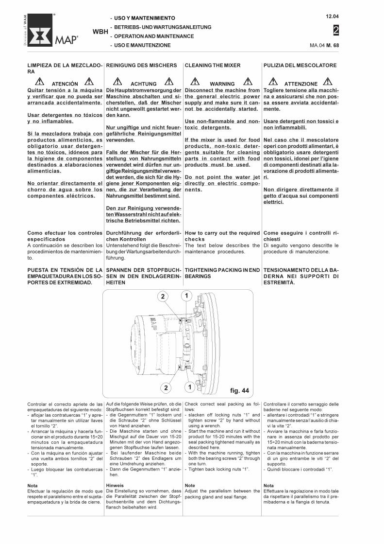
12.04
2
-
-
-
-
WBH
USO Y MANTENIMIENTO
BETRIEBS- UND WARTUNGSANLEITUNG
OPERATION AND MAINTENANCE
USO E MANUTENZIONE MA.04 M. 68
Controlar el correcto apriete de lasempaquetaduras del siguiente modo:- aflojar las contratuercas “1” y apre-
tar manualmente sin utilizar llavesel tornillo “2”.
- Arrancar la máquina y hacerla fun-cionar sin el producto durante 15÷20minutos con la empaquetaduratensionada manualmente.
- Con la máquina en función ajustaruna vuelta ambos tornillos “2” delsoporte.
- Luego bloquear las contratuercas“1”.
NotaEfectuar la regulación de modo querespete el paralelismo entre el sujeta-empaquetadura y la brida de cierre.
Auf die folgende Weise prüfen, ob dieStopfbuchsen korrekt befestigt sind:- die Gegenmuttern “1” lockern und
die Schraube “2” ohne Schlüsselvon Hand anziehen.
- Die Maschine starten und ohneMischgut auf die Dauer von 15-20Minuten mit der von Hand angezo-genen Stopfbuchse laufen lassen.
- Bei laufender Maschine beideSchrauben “2” des Endlagers umeine Umdrehung anziehen.
- Dann die Gegenmuttern “1” anzie-hen.
HinweisDie Einstellung so vornehmen, dassdie Parallelität zwischen der Stopf-buchsenbrille und dem Dichtungs-flansch beibehalten wird.
Check correct seal packing as fol-lows:- slacken off locking nuts “1” and
tighten screw “2” by hand withoutusing a wrench.
- Start the machine and run it withoutproduct for 15-20 minutes with theseal packing tightened manually asdescribed here.
- With the machine running, tightenboth the bearing screws “2” throughone turn.
- Tighten back locking nuts “1”.
NoteAdjust the parallelism between thepacking gland and seal flange.
Controllare il corretto serraggio dellebaderne nel seguente modo:- allentare i controdadi “1” e stringere
manualmente senza l’ausilio di chia-vi la vite “2”.
- Avviare la macchina e farla funzio-nare in assenza del prodotto per15÷20 minuti con la baderna tensio-nata manualmente.
- Con la macchina in funzione serraredi un giro entrambe le viti “2” delsupporto.
- Quindi bloccare i controdadi “1”.
NotaEffettuare la regolazione in modo taleda rispettare il parallelismo tra il pre-mibaderna e la flangia di tenuta.
fig. 44
PULIZIA DEL MESCOLATORE
ATTENZIONETogliere tensione alla macchi-na e assicurarsi che non pos-sa essere avviata accidental-mente.
Usare detergenti non tossici enon infiammabili.
Nel caso che il mescolatoreoperi con prodotti alimentari, èobbligatorio usare detergentinon tossici, idonei per l’igienedi componenti destinati alla la-vorazione di prodotti alimenta-ri.
Non dirigere direttamente ilgetto d’acqua sui componentielettrici.
Come eseguire i controlli ri-chiestiDi seguito vengono descritte leprocedure di manutenzione.
TENSIONAMENTO DELLA BA-DERNA NEI SUPPORTI DIESTREMITÀ.
LIMPIEZA DE LA MEZCLADO-RA
ATENCIÓNQuitar tensión a la máquinay verificar que no pueda serarrancada accidentalmente.
Usar detergentes no tóxicosy no inflamables.
Si la mezcladora trabaja conproductos alimenticios, esobligatorio usar detergen-tes no tóxicos, idóneos parala higiene de componentesdestinados a elaboracionesalimenticias.
No orientar directamente elchorro de agua sobre loscomponentes eléctricos.
Como efectuar los controlesespecificadosA continuación se describen losprocedimientos de mantenimien-to.
PUESTA EN TENSIÓN DE LAEMPAQUETADURA EN LOS SO-PORTES DE EXTREMIDAD.
REINIGUNG DES MISCHERS
ACHTUNGDie Hauptstromversorgung derMaschine abschalten und si-cherstellen, daß der Mischernicht ungewollt gestartet wer-den kann.
Nur ungiftige und nicht feuer-gefährliche Reinigungsmittelverwenden.
Falls der Mischer für die Her-stellung von Nahrungsmittelnverwendet wird dürfen nur un-giftige Reinigungsmittel verwen-det werden, die sich für die Hy-giene jener Komponenten eig-nen, die zur Verarbeitung derNahrungsmittel bestimmt sind.
Den zur Reinigung verwende-ten Wasserstrahl nicht auf elek-trische Betriebsmittel richten.
Durchführung der erforderli-chen KontrollenUntenstehend folgt die Beschrei-bung der Wartungsarbeitendurch-führung.
SPANNEN DER STOPFBUCH-SEN IN DEN ENDLAGEREIN-HEITEN
CLEANING THE MIXER
WARNINGDisconnect the machine fromthe general electric powersupply and make sure it can-not be accidentally started.
Use non-flammable and non-toxic detergents.
If the mixer is used for foodproducts, non-toxic deter-gents suitable for cleaningparts in contact with foodproducts must be used.
Do not point the water jetdirectly on electric compo-nents.
How to carry out the requiredchecksThe text below describes themaintenance procedures.
TIGHTENING PACKING IN ENDBEARINGS
2
•
1
•
2
•
1
•
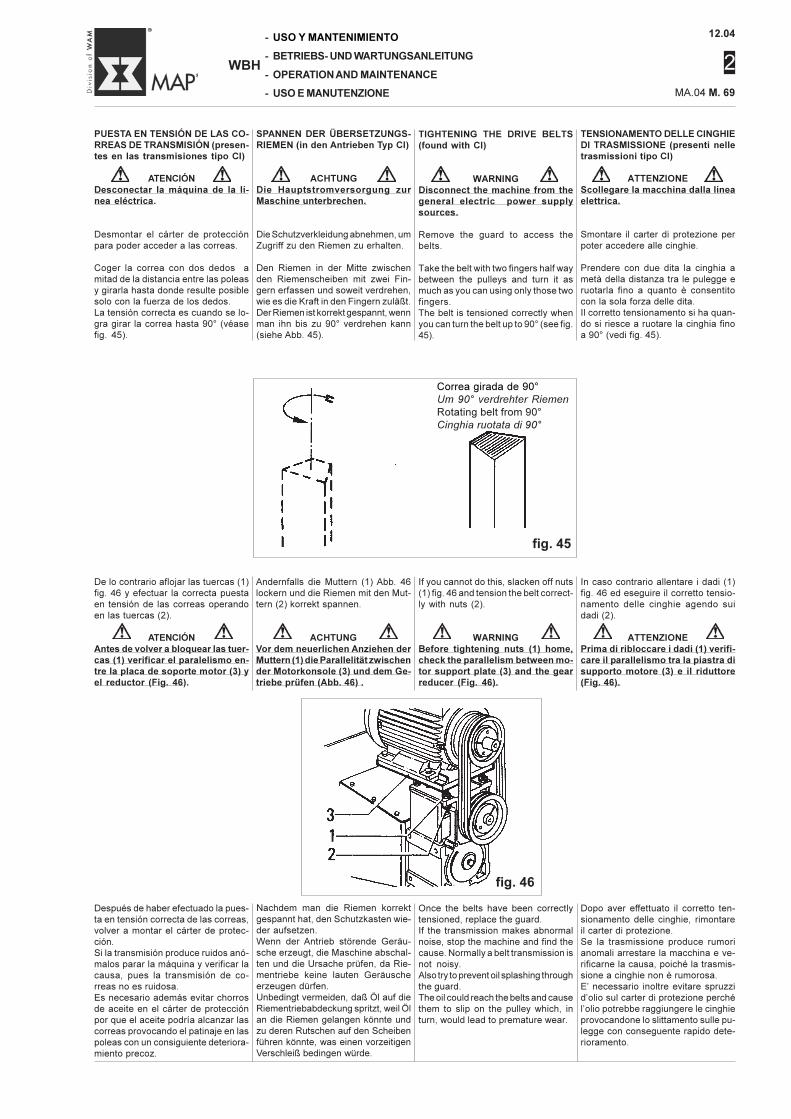
12.04
2
MA.04 M. 69
-
-
-
-
WBH
USO Y MANTENIMIENTO
BETRIEBS- UND WARTUNGSANLEITUNG
OPERATION AND MAINTENANCE
USO E MANUTENZIONE
TENSIONAMENTO DELLE CINGHIEDI TRASMISSIONE (presenti nelletrasmissioni tipo CI)
ATTENZIONEScollegare la macchina dalla lineaelettrica.
Smontare il carter di protezione perpoter accedere alle cinghie.
Prendere con due dita la cinghia ametà della distanza tra le pulegge eruotarla fino a quanto è consentitocon la sola forza delle dita.Il corretto tensionamento si ha quan-do si riesce a ruotare la cinghia finoa 90° (vedi fig. 45).
PUESTA EN TENSIÓN DE LAS CO-RREAS DE TRANSMISIÓN (presen-tes en las transmisiones tipo CI)
ATENCIÓNDesconectar la máquina de la lí-nea eléctrica.
Desmontar el cárter de protecciónpara poder acceder a las correas.
Coger la correa con dos dedos amitad de la distancia entre las poleasy girarla hasta donde resulte posiblesolo con la fuerza de los dedos.La tensión correcta es cuando se lo-gra girar la correa hasta 90° (véasefig. 45).
SPANNEN DER ÜBERSETZUNGS-RIEMEN (in den Antrieben Typ CI)
ACHTUNGDie Hauptstromversorgung zurMaschine unterbrechen.
Die Schutzverkleidung abnehmen, umZugriff zu den Riemen zu erhalten.
Den Riemen in der Mitte zwischenden Riemenscheiben mit zwei Fin-gern erfassen und soweit verdrehen,wie es die Kraft in den Fingern zuläßt.Der Riemen ist korrekt gespannt, wennman ihn bis zu 90° verdrehen kann(siehe Abb. 45).
TIGHTENING THE DRIVE BELTS(found with CI)
WARNINGDisconnect the machine from thegeneral electric power supplysources.
Remove the guard to access thebelts.
Take the belt with two fingers half waybetween the pulleys and turn it asmuch as you can using only those twofingers.The belt is tensioned correctly whenyou can turn the belt up to 90° (see fig.45).
De lo contrario aflojar las tuercas (1)fig. 46 y efectuar la correcta puestaen tensión de las correas operandoen las tuercas (2).
ATENCIÓNAntes de volver a bloquear las tuer-cas (1) verificar el paralelismo en-tre la placa de soporte motor (3) yel reductor (Fig. 46).
Andernfalls die Muttern (1) Abb. 46lockern und die Riemen mit den Mut-tern (2) korrekt spannen.
ACHTUNGVor dem neuerlichen Anziehen derMuttern (1) die Parallelität zwischender Motorkonsole (3) und dem Ge-triebe prüfen (Abb. 46) .
If you cannot do this, slacken off nuts(1) fig. 46 and tension the belt correct-ly with nuts (2).
WARNINGBefore tightening nuts (1) home,check the parallelism between mo-tor support plate (3) and the gearreducer (Fig. 46).
In caso contrario allentare i dadi (1)fig. 46 ed eseguire il corretto tensio-namento delle cinghie agendo suidadi (2).
ATTENZIONEPrima di ribloccare i dadi (1) verifi-care il parallelismo tra la piastra disupporto motore (3) e il riduttore(Fig. 46).
Correa girada de 90°Um 90° verdrehter Riemen
Rotating belt from 90°Cinghia ruotata di 90°
fig. 45
Dopo aver effettuato il corretto ten-sionamento delle cinghie, rimontareil carter di protezione.Se la trasmissione produce rumorianomali arrestare la macchina e ve-rificarne la causa, poiché la trasmis-sione a cinghie non è rumorosa.E’ necessario inoltre evitare spruzzid’olio sul carter di protezione perchél’olio potrebbe raggiungere le cinghieprovocandone lo slittamento sulle pu-legge con conseguente rapido dete-rioramento.
Once the belts have been correctlytensioned, replace the guard.If the transmission makes abnormalnoise, stop the machine and find thecause. Normally a belt transmission isnot noisy.Also try to prevent oil splashing throughthe guard.The oil could reach the belts and causethem to slip on the pulley which, inturn, would lead to premature wear.
Después de haber efectuado la pues-ta en tensión correcta de las correas,volver a montar el cárter de protec-ción.Si la transmisión produce ruidos anó-malos parar la máquina y verificar lacausa, pues la transmisión de co-rreas no es ruidosa.Es necesario además evitar chorrosde aceite en el cárter de protecciónpor que el aceite podría alcanzar lascorreas provocando el patinaje en laspoleas con un consiguiente deteriora-miento precoz.
Nachdem man die Riemen korrektgespannt hat, den Schutzkasten wie-der aufsetzen.Wenn der Antrieb störende Geräu-sche erzeugt, die Maschine abschal-ten und die Ursache prüfen, da Rie-mentriebe keine lauten Geräuscheerzeugen dürfen.Unbedingt vermeiden, daß Öl auf dieRiementriebabdeckung spritzt, weil Ölan die Riemen gelangen könnte undzu deren Rutschen auf den Scheibenführen könnte, was einen vorzeitigenVerschleiß bedingen würde.
fig. 46
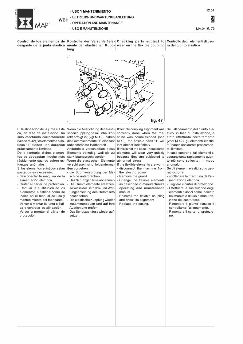
12.04
2
-
-
-
-
WBH
USO Y MANTENIMIENTO
BETRIEBS- UND WARTUNGSANLEITUNG
OPERATION AND MAINTENANCE
USO E MANUTENZIONE MA.04 M. 70
Checking parts subject towear on the flexible coupling
Controllo degli elementi di usu-ra del giunto elastico
Control de los elementos dedesgaste de la junta elástica
Kontrolle der Verschleißele-mente der elastischen Kupp-lung
Wenn die Ausrichtung der elasti-schen Kupplung beim Einbau kor-rekt erfolgt ist (vgl.M.42), habendie Gummielemente “1” eine fastunbeschränkte Haltbarkeit.Andernfalls verschleißen dieseElemente vorzeitig, weil sie zustark beansprucht werden.Wenn die elastischen Elementeverschlissen sind folgenderma-ßen vorgehen:- die Stromversorgung der Ma-
schine unterbrechen- Das Schutzgehäuse abnehmen- Die Gummielemente ersetzen,
so wie in der Betriebs- und War-tungsanleitung des Herstellersbeschrieben
- Die elastische Kupplung wiederzusammenbauen und auf ihreAusrichtung prüfen
- Das Schutzgehäuse wieder auf-setzen.
Se l’allineamento del giunto ela-stico, in fase di installazione, èstato effettuato correttamente(vedi M.42), gli elementi elastici“1” hanno una durata praticamen-te illimitata.In caso contrario, tali elementi siusurano tanto rapidamente quan-to più sono sollecitati in modoanomalo.Se gli elementi elastici sono usu-rati occorre:- scollegare la macchina dall’ali-
mentazione elettrica.- Togliere il carter di protezione.- Effettuare la sostituzione degli
elementi elastici come indicatonel manuale di uso e manuten-zione del costruttore.
- Rimontare il giunto elastico econtrollarne l’allineamento.
- Rimontare il carter di protezio-ne.
Si la alineación de la junta elásti-ca, en fase de instalación, hasido efectuada correctamente(véase M.42), los elementos elás-ticos “1” tienen una duraciónprácticamente ilimitada.De lo contrario, dichos elemen-tos se desgastan mucho másrápidamente cuando sufren es-fuerzos anómalos.Si los elementos elásticos estángastados es necesario:- desconectar la máquina de la
alimentación eléctrica.- Quitar el cárter de protección.- Efectuar la sustitución de los
elementos elásticos como seindica en el manual de uso ymantenimiento del fabricante.
- Volver a montar la junta elásti-ca y controlar su alineación.
- Volver a montar el cárter deprotección.
If flexible coupling alignment wascorrectly done when the ma-chine was commissioned (seeM.42), the flexible parts “1” willlast almost indefinitely.If this is not the case, these sameelements will wear very quicklybecause they are subjected toabnormal stress.If the flexible elements are worn:- disconnect the machine from
the electric power- Remove the guard- Change the flexible elements
as described in manufacturer’soperating and maintenancemanual
- Reinstall the flexible couplingand check its alignment
- Replace the casing.
fig. 47
12.04
2
MA.04 M. 71
-
-
-
-
WBH
USO Y MANTENIMIENTO
BETRIEBS- UND WARTUNGSANLEITUNG
OPERATION AND MAINTENANCE
USO E MANUTENZIONE
SUPPORTI ALBERO ROTORE
ATTENZIONEEffettuare le operazioni di smon-taggio e montaggio dei supporticon la macchina scollegata dallarete elettrica agendo sull’interrut-tore provvisto della chiave di si-curezza e della rete pneumatica.
La chiave dell’interruttore deveessere in possesso del manuten-tore autorizzato.
Utilizzando l’aria compressa perla pulizia della macchina, proteg-gersi gli occhi con occhiali antin-fortunistici e comunque non su-perare mai la pressione di 2 bar.
Non utilizzare mai benzina, sol-venti o altri liquidi infiammabilicome detergenti, ricorrere invecea solventi commerciali autorizzatinon infiammabili e non tossici.
Quando il supporto presenta ecces-sivi surriscaldamenti o elevata ru-morosità occorre intervenire per unasua revisione.
Si precisa che i cuscinetti dei sup-porti, data anche la loro bassa ve-locità di lavoro, sono progettati perdurare un elevato numero di ore.Pertanto prima di sostituire i cusci-netti è bene verificare che l’incon-veniente (rumore) sia generato daun altro componente come adesempio, una rumorosità costante,che nel tempo non aumenta, oppu-re un battito a frequenza regolare,non provengano dal cuscinetto.Smontato completamente il suppor-to, procedere ad una accurata puli-zia di ogni particolare verificando lapresenza di usure o incrinature.In particolare verificare lo stato del-l’albero che non deve presentareanomalie abrasioni o rigature.In caso affermativo, contattare ilcostruttore per valutare il danno estabilire l’eventuale sostituzione.
NotaSostituire tutte le guarnizioni e letenute (anche se apparentementeintegre) ogni volta che i supportivengono smontati nelle loro parti,poiché un eventuale trafilamentocauserebbe un arresto della mac-china fuori programma.
SOPORTES ÁRBOL ROTOR
ATENCIÓNEfectuar las operaciones dedesmontaje y montaje de lossoportes con la máquina des-conectada de la red eléctricaoperando con el interruptor conllave de seguridad y desconec-tada también de la red neumáti-ca.
La llave del interruptor debequedar en manos del técnico demantenimiento autorizado.
Utilizando el aire comprimidopara la limpieza de la máquina,protegerse los ojos con gafasde seguridad y de todos modosno superar jamás la presión de2 bar.
No utilizar nunca gasolina, sol-ventes u otros líquidos inflama-bles como detergentes, recurriren cambio a solventes comer-ciales autorizados no inflama-bles y no tóxicos.
Cuando el soporte presenta ex-cesivos sobrecalentamientos oelevado nivel de ruido es nece-sario efectuar una revisión.
Precisamos que los cojinetes delos soportes, dada su baja veloci-dad de trabajo, se han estudiadopara durar un elevado número dehoras.Por lo tanto antes de sustituir loscojinetes se debe verificar que elinconveniente (ruido) no sea ge-nerado por otro componentecomo por ejemplo, un ruido cons-tante, que en el tiempo no au-menta, o bien una pulsación defrecuencia regular que no proven-ga del cojinete.Una vez desmontado completa-mente el soporte, efectuar unameticulosa limpieza de cadacomponente verificando la pre-sencia de desgaste o resquebra-duras.En particular verificar el estadodel árbol que no debe presentaranómalas abrasiones o rayas. Encaso afirmativo, contactar al fa-bricante para evaluar el daño yestablecer la eventual sustitución.
NotaSustituir todas las juntas y los cie-rres (aún si se ven aparentemen-te íntegros) cada vez que se des-montan los soportes, ya que unaeventual pérdida causaría unaparada de la máquina fuera deprograma.
MISCHERWELLENLAGERUN-GEN
ACHTUNGVor Montage und Demontage derLager Stromversorgung mittelsdurch Sicherheitsschlüssel gesi-cherten Hauptschalter abschal-ten. Die Maschine auch von derDruckluftversorgung trennen.
Die die Wartung durchführfendePerson muß den oben beschrie-benen Sicherheitsschlüssel beisich führen.
Beim Reinigen der Maschine mitDruckluft Augen durch Schutz-brille schützen. Der Druck darfnie über 2 bar ansteigen.
Niemals Benzin, Lösemittel oderandere feuergefährliche Flüssig-keiten als Reinigungsmittel ver-wenden. Ausschließlich handels-übliche und genehmigte Lösemit-tel, die weder feuergefährlichnoch giftig sind, verwenden.
Wenn Endlagereinheiten zu starkeVibrationen aufweisen oder heißwerden, Kontrolle vornehmen.
Die Lager sind angesichts der nied-rigen Drehzahlen für eine hohe An-zahl von Betriebsstunden ausge-legt. Bevor man die Lager ersetzt,sollte daher sichergestellt werden,daß nicht andere Komponenten Ver-ursacher der Störung sind (Geräu-sche). So wird beispielsweise eindauerndes Geräusch, das im Laufeder Zeit nicht zunimmt, oder einSchlagen mit regelmäßiger Fre-quenz nicht durch Lager verursacht.Lager ganz ausbauen, alle Teilegründlich reinigen und sicherstel-len, daß keine Verschleißstellen oderRisse vorhanden sind.Insbesondere prüfen, ob der Zu-stand der Welle in Ordnung ist. Siedarf weder Schleifstellen noch Ril-len aufweisen.Ist dies doch der Fall, wenden Siesich an der Hersteller, um den Scha-den beurteilen zu lassen und dieWelle ggfls. zu ersetzen.
HinweisJedesmal wenn die Endlagerein-heiten in ihre Bestandteile zerlegtwerden, alle Dichtungen ersetzen(auch wenn diese scheinbar nochunbeschädigt sind), da etwaigeLeckagen ein Stehenbleiben derMaschine und damit einen Be-triebsausfall zur Folge hätten.
ROTOR SHAFT BEARINGS
WARNINGThe bearings must be mountedand removed with the machinedisconnected from the electricalpower mains using the keylockswitch. Also disconnect the com-press air supply.
The keylock switch key must bekept by the authorized ServiceEngineer.
If one uses compressed air toclean the machine, always wearsafety goggles and never ex-ceed a pressure of 2 bar.
Do not use petrol (gasoline), sol-vents or other flammable liquidsas detergents. Always use au-thorized non-flammable and non-toxic commercial products.
When the end bearings becometoo hot or make excessive noise,they will have to be checked.
Note that the bearings in the as-semblies, given their low workingspeed, have been designed towork for a very large number ofwork hours.Thus, before changing the bear-ings, it is standard practice to firstcheck whether the problem (noise)is caused by some other part, forexample, continuous noise thatdoes not increase in time or asteady beating, will not come froma bearing.Once the support has been com-pletely dismounted, clean all partsthoroughly, check for wear or nicks.In particular, check the conditionof the shaft which must not showany abnormal scratching or scor-ing.If there is, contact the Manufactur-er to assess the damage and de-cide on possible replacement.
NoteReplace all gaskets and seals(even if apparently in good condi-tion) whenever you dismount thebearing assembly. Any leakagewill cause an unscheduled ma-chine shut-down.
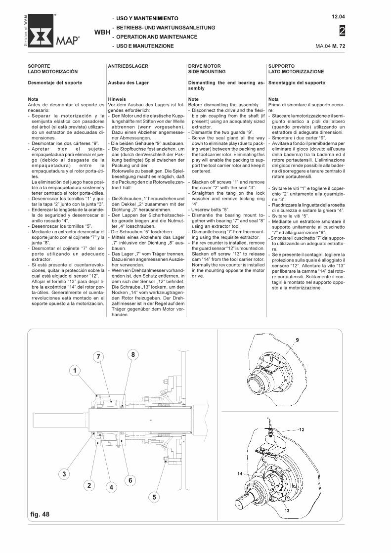
12.04
2
-
-
-
-
WBH
USO Y MANTENIMIENTO
BETRIEBS- UND WARTUNGSANLEITUNG
OPERATION AND MAINTENANCE
USO E MANUTENZIONE MA.04 M. 72
SUPPORTOLATO MOTORIZZAZIONE
Smontaggio del supporto
NotaPrima di smontare il supporto occor-re:- Staccare la motorizzazione e il semi-
giunto elastico a pioli dall’albero(quando previsto) utilizzando unestrattore di adeguate dimensioni.
- Smontare i due carter “9”.- Avvitare a fondo il premibaderna per
eliminare il gioco (dovuto all’usuradella baderna) tra la baderna ed ilrotore portautensili. L’eliminazionedel gioco rende possibile alla bader-na di sorreggere e tenere centrato ilrotore portautensili.
- Svitare le viti “1” e togliere il coper-chio “2” unitamente alla guarnizio-ne “3”.
- Raddrizzare la linguetta della rosettadi sicurezza e svitare la ghiera “4”.
- Svitare le viti “5”.- Mediante un estrattore smontare il
supporto unitamente al cuscinetto“7” ed alla guarnizione “8”.
- Smontare il cuscinetto “7” dal suppor-to utilizzando un adeguato estratto-re.
- Se è presente il contagiri, togliere laprotezione sulla quale è alloggiato ilsensore “12”. Allentare la vite “13”per liberare la camma “14” dal roto-re portautensili. Solitamente il con-tagiri è montato nel supporto oppo-sto alla motorizzazione.
SOPORTELADO MOTORIZACIÓN
Desmontaje del soporte
NotaAntes de desmontar el soporte esnecesario:- Separar la motorización y la
semijunta elástica con pasadoresdel árbol (si está prevista) utilizan-do un extractor de adecuadas di-mensiones.
- Desmontar los dos cárteres “9”.- Apretar bien el sujeta-
empaquetadura para eliminar el jue-go (debido al desgaste de laempaquetadura) entre laempaquetadura y el rotor porta-úti-les.La eliminación del juego hace posi-ble a la empaquetadura sostener ytener centrado el rotor porta-útiles.
- Desenroscar los tornillos “1” y qui-tar la tapa “2” junto con la junta “3”.
- Enderezar la lengüeta de la arande-la de seguridad y desenroscar elanillo roscado “4”.
- Desenroscar los tornillos “5”.- Mediante un extractor desmontar el
soporte junto con el cojinete “7” y lajunta “8”.
- Desmontar el cojinete “7” del so-porte uti l izando un adecuadoextractor.
- Si está presente el cuentarrevolu-ciones, quitar la protección sobre lacual está alojado el sensor “12”.Aflojar el tornillo “13” para dejar li-bre la excéntrica “14” del rotor por-ta-útiles. Generalmente el cuenta-rrevoluciones está montado en elsoporte opuesto a la motorización.
DRIVE MOTORSIDE MOUNTING
Dismantling the end bearing as-sembly
NoteBefore dismantling the assembly:- Disconnect the drive and the flexi-
ble pin coupling from the shaft (ifpresent) using an adequately sizedextractor.
- Dismantle the two guards “9”.- Screw the seal gland all the way
down to eliminate play (due to pack-ing wear) between the packing andthe tool carrier rotor. Eliminating thisplay will enable the packing to sup-port the tool carrier rotor and keep itcentered.
- Slacken off screws “1” and removethe cover “2” with the seal “3”.
- Straighten the tang on the lockwascher and remove locking ring“4”.
- Unscrew bolts “5”.- Dismantle the bearing mount to-
gether with bearing “7” and seal “8”using an extractor tool.
- Dismantle bearig “7” from the mount-ing using the requisite extractor.
- If a rev counter is installed, removethe guard sensor “12” is mounted on.Slacken off screw “13” to releasecam “14” from the tool carrier rotor.Normally the rev counter is installedin the mounting opposite the motordrive.
ANTRIEBSLAGER
Ausbau des Lager
HinweisVor dem Ausbau des Lagers ist fol-gendes erforderlich:- Den Motor und die elastische Kupp-
lungshälfte mit Stiften von der Welleabtrennen (wenn vorgesehen).Dazu einen Abzieher angemesse-ner Abmessungen.
- Die beiden Gehäuse “9” ausbauen.- Die Stopfbuchse fest anziehen, um
das (durch denVerschleiß der Pak-kung bedingte) Spiel zwischen derPackung und derRotorwelle zu beseitigen. Die Spiel-beseitigung macht es möglich, daßdie Packung den die Rotorwelle zen-triert hält.
- Die Schrauben „1“ herausdrehen undden Dekkel „2“ zusammen mit derDichtung „3“ herausnehmen.
- Den Lappen der Sicherheitsschei-be gerade biegen und die Nutmut-ter „4“ losschrauben.
- Die Schrauben “5” losdrehen.- Mittels eines Abziehers das Lager
„7“ inklusive der Dichtung „8“ aus-bauen.
- Das Lager „7“ vom Träger trennen.Dazu einen angemessenen Auszie-her verwenden.
- Wenn ein Drehzahlmesser vorhand-enden ist, den Schutz entfernen, indem sich der Sensor „12“ befindet.Die Schraube „13“ lockern, um denNocken „14“ vom werkzeugtragen-den Rotor freizugeben. Der Dreh-zahlmesser ist in der Regel auf demTräger gegenüber dem Motor vor-handen.
fig. 48
7
•
1
•
8
•
3
•
2
•
4
•
6
•
5
•
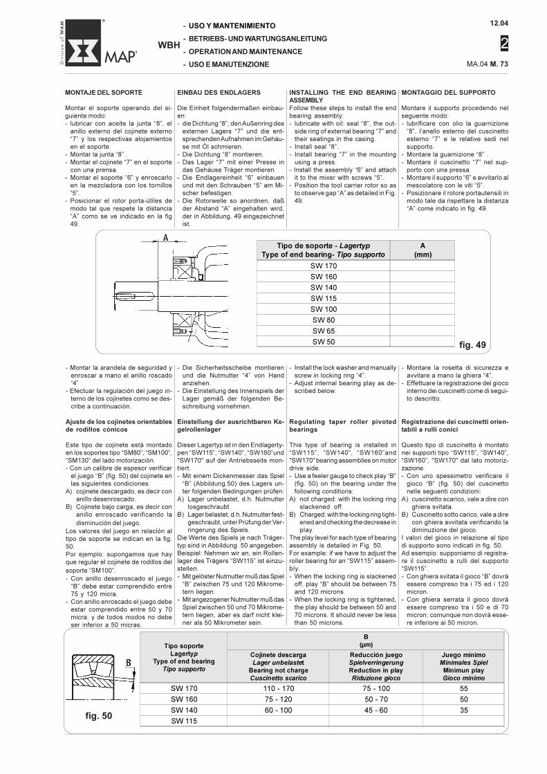
12.04
2
MA.04 M. 73
-
-
-
-
WBH
USO Y MANTENIMIENTO
BETRIEBS- UND WARTUNGSANLEITUNG
OPERATION AND MAINTENANCE
USO E MANUTENZIONE
MONTAJE DEL SOPORTE
Montar el soporte operando del si-guiente modo:- lubricar con aceite la junta “8”, el
anillo externo del cojinete externo“7” y los respectivas alojamientosen el soporte.
- Montar la junta “8” .- Montar el cojinete “7” en el soporte
con una prensa.- Montar el soporte “6” y enroscarlo
en la mezcladora con los tornillos“5”.
- Posicionar el rotor porta-útiles demodo tal que respete la distancia“A” como se ve indicado en la fig49.
MONTAGGIO DEL SUPPORTO
Montare il supporto procedendo nelseguente modo:- lubrificare con olio la guarnizione
“8”, l’anello esterno del cuscinettoesterno “7” e le relative sedi nelsupporto.
- Montare la guarnizione “8” .- Montare il cuscinetto “7” nel sup-
porto con una pressa.- Montare il supporto “6” e avvitarlo al
mescolatore con le viti “5”.- Posizionare il rotore portautensili in
modo tale da rispettare la distanza“A” come indicato in fig. 49.
EINBAU DES ENDLAGERS
Die Einheit folgendermaßen einbau-en:- die Dichtung “8”, den Außenring des
externen Lagers “7” und die ent-sprechenden Aufnahmen im Gehäu-se mit Öl schmieren.
- Die Dichtung “8” montieren.- Das Lager “7” mit einer Presse in
das Gehäuse Träger montieren.- Die Endlagereinheit “6” einbauen
und mit den Schrauben “5” am Mi-scher befestigen.
- Die Rotorwelle so anordnen, daßder Abstand “A” eingehalten wird,der in Abbildung. 49 eingezeichnetist.
INSTALLING THE END BEARINGASSEMBLYFollow these steps to install the endbearing assembly:- lubricate with oil: seal “8”, the out-
side ring of external bearing “7” andtheir seatings in the casing.
- Install seal “8”.- Install bearing “7” in the mounting
using a press.- Install the assembly “6” and attach
it to the mixer with screws “5”.- Position the tool carrier rotor so as
to observe gap “A” as detailed in Fig.49.
- Install the lock washer and manuallyscrew in locking ring “4”.
- Adjust internal bearing play as de-scribed below.
Regulating taper roller pivotedbearings
This type of bearing is installed in“SW115”, “SW140”, “SW160”and"SW170" bearing assemblies on motordrive side.- Use a feeler gauge to check play “B”
(fig. 50) on the bearing under thefollowing conditions:
A) not charged: with the locking ringslackened off.
B) Charged: with the locking ring tight-ened and checking the decrease inplay.
The play level for each type of bearingassembly is detailed in Fig. 50.For example: if we have to adjust theroller bearing for an “SW115” assem-bly.- When the locking ring is slackened
off, play “B” should be between 75and 120 microns.
- When the locking ring is tightened,the play should be between 50 and70 microns. It should never be lessthan 50 microns.
- Montare la rosetta di sicurezza eavvitare a mano la ghiera “4”.
- Effettuare la registrazione del giocointerno dei cuscinetti come di segui-to descritto.
Registrazione dei cuscinetti orien-tabili a rulli conici
Questo tipo di cuscinetto è montatonei supporti tipo “SW115”, “SW140”,“SW160”, "SW170" dal lato motoriz-zazione.- Con uno spessimetro verificare il
gioco “B” (fig. 50) del cuscinettonelle seguenti condizioni:
A) cuscinetto scarico, vale a dire conghiera svitata.
B) Cuscinetto sotto carico, vale a direcon ghiera avvitata verificando ladiminuzione del gioco.
I valori del gioco in relazione al tipodi supporto sono indicati in fig. 50.Ad esempio: supponiamo di registra-re il cuscinetto a rulli del supporto“SW115”.- Con ghiera svitata il gioco “B” dovrà
essere compreso tra i 75 ed i 120micron.
- Con ghiera serrata il gioco dovràessere compreso tra i 50 e di 70micron; comunque non dovrà esse-re inferiore ai 50 micron.
- Die Sicherheitsscheibe montierenund die Nutmutter “4” von Handanziehen.
- Die Einstellung des Innenspiels derLager gemäß der folgenden Be-schreibung vornehmen.
Einstellung der ausrichtbaren Ke-gelrollenlager
Dieser Lagertyp ist in den Endlagerty-pen “SW115”, “SW140”, “SW160”und"SW170" auf der Antriebsseite mon-tiert.- Mit einem Dickenmesser das Spiel
“B” (Abbildung.50) des Lagers un-ter folgenden Bedingungen prüfen:
A) Lager unbelastet, d.h. Nutmutterlosgeschraubt
B) Lager belastet, d.h. Nutmutter fest-geschraubt, unter Prüfung der Ver-ringerung des Spiels.
Die Werte des Spiels je nach Träger-typ sind in Abbildung. 50 angegeben.Beispiel: Nehmen wir an, ein Rollen-lager des Trägers “SW115” ist einzu-stellen.- Mit gelöster Nutmutter muß das Spiel
“B” zwischen 75 und 120 Mikrome-tern liegen.
- Mit angezogener Nutmutter muß dasSpiel zwischen 50 und 70 Mikrome-tern liegen, aber es darf nicht klei-ner als 50 Mikrometer sein.
- Montar la arandela de seguridad yenroscar a mano el anillo roscado“4”
- Efectuar la regulación del juego in-terno de los cojinetes como se des-cribe a continuación.
Ajuste de los cojinetes orientablesde rodillos cónicos
Este tipo de cojinete está montadoen los soportes tipo “SM80”, “SM100”,“SM130” del lado motorización.- Con un calibre de espesor verificar
el juego “B” (fig. 50) del cojinete enlas siguientes condiciones:
A) cojinete descargado, es decir conanillo desenroscado.
B) Cojinete bajo carga, es decir conanillo enroscado verificando ladisminución del juego.
Los valores del juego en relación altipo de soporte se indican en la fig.50.Por ejemplo: supongamos que hayque regular el cojinete de rodillos delsoporte “SM100”.- Con anillo desenroscado el juego
“B” debe estar comprendido entre75 y 120 micra.
- Con anillo enroscado el juego debeestar comprendido entre 50 y 70micra; y de todos modos no debeser inferior a 50 micras.
fig. 49
fig. 50
Tipo de soporte - Lagertyp
Type of end bearing- Tipo supporto
A
(mm)
SW 170
SW 160
SW 140
SW 115
SW 100
SW 80
SW 65
SW 50
Tipo soporte
Lagertyp
Type of end bearing
Tipo supporto
B
(µm)
Cojinete descarga
Lager unbelastet
Bearing not charge
Cuscinetto scarico
Reducción juego
Spielverringerung
Reduction in play
Riduzione gioco
Juego mínimo
Minimales Spiel
Minimun play
Gioco minimo
SW 170 110 - 170 75 - 100 55
SW 160 75 - 120 50 - 70 50
SW 140 60 - 100 45 - 60 35
SW 115
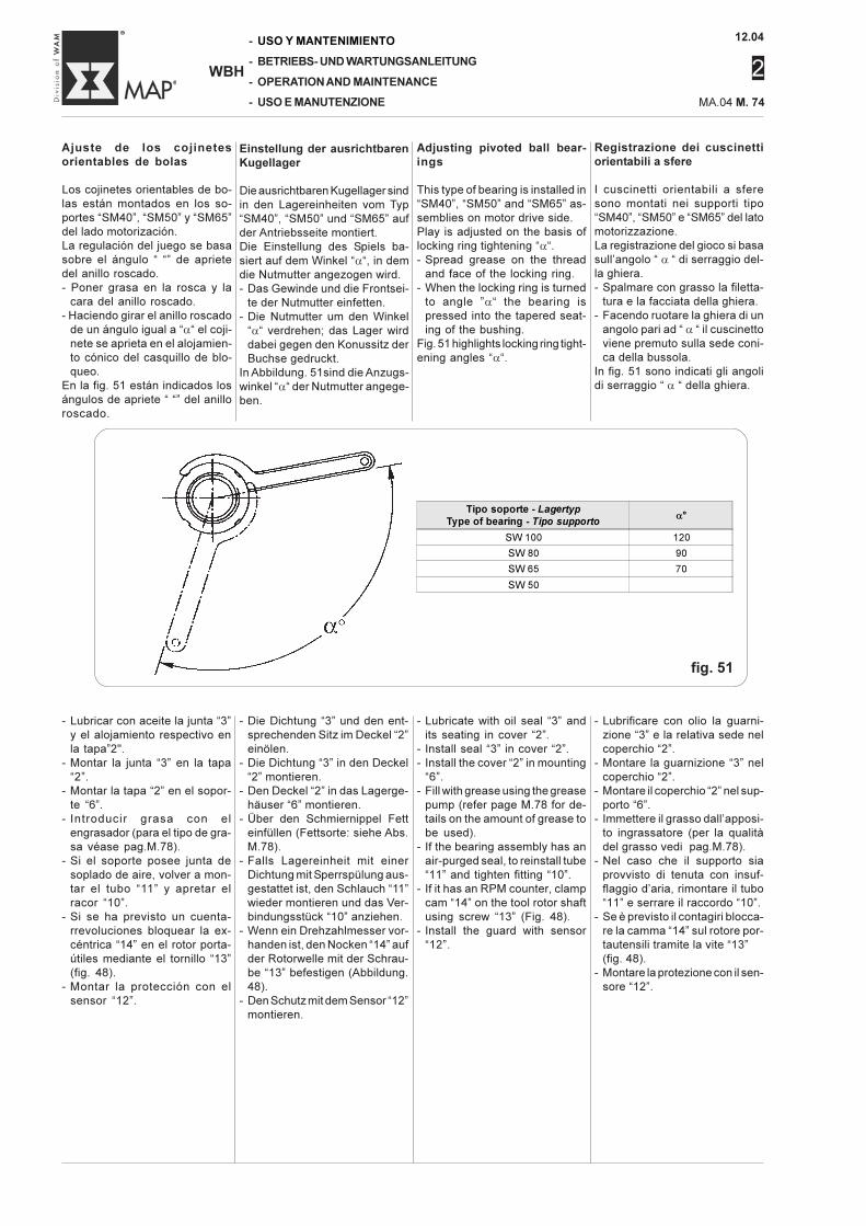
12.04
2
-
-
-
-
WBH
USO Y MANTENIMIENTO
BETRIEBS- UND WARTUNGSANLEITUNG
OPERATION AND MAINTENANCE
USO E MANUTENZIONE MA.04 M. 74
Adjusting pivoted ball bear-ings
This type of bearing is installed in“SM40”, “SM50” and “SM65” as-semblies on motor drive side.Play is adjusted on the basis oflocking ring tightening “α“.- Spread grease on the thread
and face of the locking ring.- When the locking ring is turned
to angle ”α“ the bearing ispressed into the tapered seat-ing of the bushing.
Fig. 51 highlights locking ring tight-ening angles “α“.
Registrazione dei cuscinettiorientabili a sfere
I cuscinetti orientabili a sferesono montati nei supporti tipo“SM40”, “SM50” e “SM65” del latomotorizzazione.La registrazione del gioco si basasull’angolo “ α “ di serraggio del-la ghiera.- Spalmare con grasso la filetta-
tura e la facciata della ghiera.- Facendo ruotare la ghiera di un
angolo pari ad “ α “ il cuscinettoviene premuto sulla sede coni-ca della bussola.
In fig. 51 sono indicati gli angolidi serraggio “ α “ della ghiera.
Einstellung der ausrichtbarenKugellager
Die ausrichtbaren Kugellager sindin den Lagereinheiten vom Typ“SM40”, “SM50” und “SM65” aufder Antriebsseite montiert.Die Einstellung des Spiels ba-siert auf dem Winkel “α“, in demdie Nutmutter angezogen wird.- Das Gewinde und die Frontsei-
te der Nutmutter einfetten.- Die Nutmutter um den Winkel
“α“ verdrehen; das Lager wirddabei gegen den Konussitz derBuchse gedruckt.
In Abbildung. 51sind die Anzugs-winkel “α“ der Nutmutter angege-ben.
Ajuste de los cojinetesorientables de bolas
Los cojinetes orientables de bo-las están montados en los so-portes “SM40”, “SM50” y “SM65”del lado motorización.La regulación del juego se basasobre el ángulo “ “” de aprietedel anillo roscado.- Poner grasa en la rosca y la
cara del anillo roscado.- Haciendo girar el anillo roscado
de un ángulo igual a “α“ el coji-nete se aprieta en el alojamien-to cónico del casquillo de blo-queo.
En la fig. 51 están indicados losángulos de apriete “ “” del anilloroscado.
- Lubricar con aceite la junta “3”y el alojamiento respectivo enla tapa”2".
- Montar la junta “3” en la tapa“2”.
- Montar la tapa “2” en el sopor-te “6”.
- Introducir grasa con elengrasador (para el tipo de gra-sa véase pag.M.78).
- Si el soporte posee junta desoplado de aire, volver a mon-tar el tubo “11” y apretar elracor “10”.
- Si se ha previsto un cuenta-rrevoluciones bloquear la ex-céntrica “14” en el rotor porta-útiles mediante el tornillo “13”(fig. 48).
- Montar la protección con elsensor “12”.
- Lubrificare con olio la guarni-zione “3” e la relativa sede nelcoperchio “2”.
- Montare la guarnizione “3” nelcoperchio “2”.
- Montare il coperchio “2” nel sup-porto “6”.
- Immettere il grasso dall’apposi-to ingrassatore (per la qualitàdel grasso vedi pag.M.78).
- Nel caso che il supporto siaprovvisto di tenuta con insuf-flaggio d’aria, rimontare il tubo“11” e serrare il raccordo “10”.
- Se è previsto il contagiri blocca-re la camma “14” sul rotore por-tautensili tramite la vite “13”(fig. 48).
- Montare la protezione con il sen-sore “12”.
- Die Dichtung “3” und den ent-sprechenden Sitz im Deckel “2”einölen.
- Die Dichtung “3” in den Deckel“2” montieren.
- Den Deckel “2” in das Lagerge-häuser “6” montieren.
- Über den Schmiernippel Fetteinfüllen (Fettsorte: siehe Abs.M.78).
- Falls Lagereinheit mit einerDichtung mit Sperrspülung aus-gestattet ist, den Schlauch “11”wieder montieren und das Ver-bindungsstück “10” anziehen.
- Wenn ein Drehzahlmesser vor-handen ist, den Nocken “14” aufder Rotorwelle mit der Schrau-be “13” befestigen (Abbildung.48).
- Den Schutz mit dem Sensor “12”montieren.
- Lubricate with oil seal “3” andits seating in cover “2”.
- Install seal “3” in cover “2”.- Install the cover “2” in mounting
“6”.- Fill with grease using the grease
pump (refer page M.78 for de-tails on the amount of grease tobe used).
- If the bearing assembly has anair-purged seal, to reinstall tube“11” and tighten fitting “10”.
- If it has an RPM counter, clampcam “14” on the tool rotor shaftusing screw “13” (Fig. 48).
- Install the guard with sensor“12”.
fig. 51
Tipo soporte - Lagertyp
Type of bearing - Tipo supportoα°
SW 100 120
SW 80 90
SW 65 70
SW 50
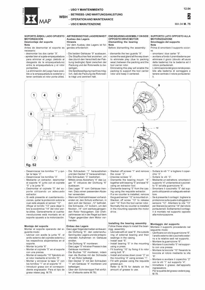
12.04
2
MA.04 M. 75
-
-
-
-
WBH
USO Y MANTENIMIENTO
BETRIEBS- UND WARTUNGSANLEITUNG
OPERATION AND MAINTENANCE
USO E MANUTENZIONE
ABTRIEBSSEITIGE LAGEREINHEITAusbau des LagersHinweisVor dem Ausbau des Lagers ist fol-gendes erforderlich:
- Die beiden Gehäuse “9” ausbauen.- Die Stopfbuchse fest anziehen, um
das (durch den Verschleiß der Pak-kung bedingte) Spiel zwischen derPackung und der Rotorwelle zu be-seitigen.Die Spielbeseitigung macht es mög-lich, daß die Packung die Rotorwel-le trägt und zentriert hält.
SUPPORTO LATO OPPOSTO ALLAMOTORIZZAZIONESmontaggio del supportoNotaPrima di smontare il supporto occor-re:- smontare i due carter “9”.- avvitare a fondo il premibaderna per
eliminare il gioco (dovuto all’usuradella baderna) tra la baderna ed ilrotore portautensili.L’eliminazione del gioco rende possi-bile alla baderna di sorreggere etenere centrato il rotore portautensi-li.
- Svitare le viti “1” e togliere il coper-chio “2”.
- Svitare le viti “3”.- Mediante un estrattore, smontare il
supporto “4” unitamente al cuscinet-to “5” ed alla guarnizione “6”.
- Smontare il cuscinetto “5” dal sup-porto utilizzando un adeguato estrat-tore.
- Se è presente il contagiri, togliere laprotezione sulla quale è alloggiato ilsensore “12”. Allentare la vite “13”per liberare la camma “14” dal rotoreportautensili. Solitamente il contagi-ri è montato nel supporto oppostoalla motorizzazione.
Montaggio del supportoMontare il supporto procedendo nelseguente modo:- lubrificare con olio la guarnizione “6”,
l’anello esterno del cuscinetto ester-no e le relative sedi nel supporto.
- Montare la guarnizione “6” .- Montare il cuscinetto “5” nel suppor-
to con una pressa.- Montare la boccola “10” fissando la
boccola al rotore mediante la vite“8”.
- Montare e avvitare il coperchio “2”con le viti “1” sul supporto “4”.
- Immettere il grasso dall’appositoingrassatore.Per la qualità del grasso vedere pag.M.78.
- Die Schrauben “1” herausdrehenund den Deckel “2” herausnehmen.
- Die Schrauben “3” losdrehen.Mittels eines Abziehers “4” das La-ger “5” inklusive der Dichtung “6”ausbauen.
- Das Lager “5” vom Gehäuse tren-nen. Dazu einen passenden Abzie-her verwenden.
- Wenn ein Drehzahlmesser vorhand-enden ist, den Schutz entfernen, indem sich der Sensor „12“ befindet.Die Schraube „13“ lockern, um denNocken „14“ vom werkzeugtragen-den Rotor freizugeben. Der Dreh-zahlmesser ist in der Regel auf demTräger gegenüber dem Motor vor-handen.
Einbau des LagersDas Lager folgendermaßen einbauen:- die Dichtung “6”, den externenAu-
ßenring des Lagers und die entspre-chenden Aufnahmen im Gehäuseeinölen.
- Die Dichtung “6” montieren.- Das Lager “5” mit einer Presse in das
Gehäuse montieren.- Die Buchse “10” montieren, indem
man die Buchse mit der Schraube“8” am Rotor befestigt.
- Den Deckel “2” mit den Schrauben“1” am Gehäuse “4” montieren undbefestigen.
- Über den Schmiernippel Fett einfül-len (Fettsorte siehe M.78).
SOPORTE ÁRBOL LADO OPUESTOMOTORIZACIÓNDesmontaje del soporteNotaAntes de desmontar el soporte esnecesario:- desmontar los dos carter “9”.- apretar bien el sujeta-empaquetadura
para eliminar el juego (debido aldesgaste de la empaquetadura)entre la empaquetadura y el rotorportaútiles.La eliminación del juego hace posi-ble a la empaquetadura sostener ytener centrado el rotor porta-útiles.
- Desenroscar los tornillos “1” y qui-tar la tapa “2”.
- Desenroscar los tornillos “3”.- Mediante un extractor, desmontar
el soporte “4” junto con el cojinete“5” y la junta “6”.
- Desmontar el cojinete “5” del so-porte uti l izando un adecuadoextractor.
- Si está presente el cuentarrevolu-ciones, quitar la protección sobre lacual está alojado el sensor “12”.Aflojar el tornillo “13” para dejar li-bre la excéntrica “14” del rotor por-ta-útiles. Generalmente el cuenta-rrevoluciones está montado en elsoporte opuesto a la motorización.
Montaje del soporteMontar el soporte operando del si-guiente modo:- lubricar con aceite la junta “6”, el
anillo externo del cojinete externo ylos respectivos alojamientos en elsoporte.
- Montar la junta “6” .- Montar el cojinete “5” en el soporte
con una prensa.- Montar el casquillo “10” fijándolo en
el rotor mediante el tornillo “8”.- Montar y enroscar la tapa “2” con
los tornillos “1” en el soporte “4”.- Introducir grasa con el correspon-
diente engrasador. Para el tipo degrasa véase pag. M.78.
END BEARING ASSEMBLY ON SIDEOPPOSITE DRIVE MOTORDismantling the bearingNoteBefore dismantling the assembly:
- dismantle the two guards “9”.- screw the seal gland all the way down
to eliminate play (due to packingwear) between the packing and thetool carrier rotor.Eliminating this play will enable thepacking to support the tool carrierrotor and keep it centered.
- Slacken off screws “1” and removethe cover “2”.
- Unscrew screws “3”.- Dismantle the bearing mount “4”
together with bearing “5” and seal “6”using an extractor tool.
- Dismantle bearing “5” from the cas-ing using the requisite extractor.
- If a rev counter is installed, removethe guard sensor “12” is mounted on.Slacken off screw “13” to releasecam “14” from the tool carrier rotor.Normally the rev counter is installedin the mounting opposite the motordrive.
Installing the bearing assemblyFollow these steps to install the bear-ingg assembly:- lubricate with oil: seal “6”, the outside
ring of external bearing and theirseatings in the casing.
- Install seal “6”.- Install bearing “5” in the mounting
using a press.- Fit bushing “10” by fixing it to rotor
using bolt “8”.- Install and screw down cover “2” on
the mounting “4” using screws “1”.- Fill with grease using the requisite
grease gun.Refer to M.78 for details on theamount of grease to use.
fig. 52
3
•
5
•
2
•
10
•
1
•
8
•
4
•
6
•
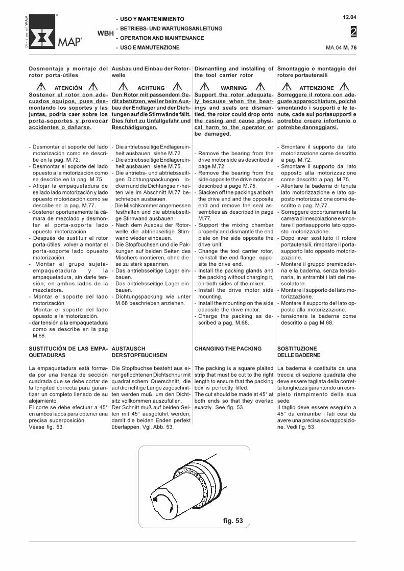
12.04
2
-
-
-
-
WBH
USO Y MANTENIMIENTO
BETRIEBS- UND WARTUNGSANLEITUNG
OPERATION AND MAINTENANCE
USO E MANUTENZIONE MA.04 M. 76
fig. 53
Smontaggio e montaggio delrotore portautensili
ATTENZIONESorreggere il rotore con ade-guate apparecchiature, poichèsmontando i supporti e le te-nute, cade sui portasupporti epotrebbe creare infortunio opotrebbe danneggiarsi.
- Smontare il supporto dal latomotorizzazione come descrittoa pag. M.72.
- Smontare il supporto dal latoopposto alla motorizzazionecome descritto a pag. M.75.
- Allentare la baderna di tenutalato motorizzazione e lato op-posto motorizzazione come de-scritto a pag. M.77.
- Sorreggere opportunamente lacamera di mescolazione e smon-tare il portasupporto lato oppo-sto motorizzazione.
- Dopo aver sostituito il rotoreportautensili, rimontare il porta-supporto lato opposto motoriz-zazione.
- Montare il gruppo premibader-na e la baderna, senza tensio-narla, in entrambi i lati del me-scolatore.
- Montare il supporto del lato mo-torizzazione.
- Montare il supporto del lato op-posto alla motorizzazione.
- tensionare la baderna comedescritto a pag M.68.
SOSTITUZIONEDELLE BADERNE
La baderna è costituita da unatreccia di sezione quadrata chedeve essere tagliata della corret-ta lunghezza garantendo un com-pleto riempimento della suasede.Il taglio deve essere eseguito a45° da entrambe i lati così daavere una precisa sovrapposizio-ne. Vedi fig. 53.
Dismantling and installing ofthe tool carrier rotor
WARNINGSupport the rotor adequate-ly because when the bear-ings and seals are disman-tled, the rotor could drop ontothe casing and cause physi-cal harm to the operator orbe damaged.
- Remove the bearing from thedrive motor side as described apage M.72.
- Remove the bearing from theside opposite the drive motor asdescribed a page M.75.
- Slacken off the packings at boththe drive end and the oppositeend and remove the seal as-semblies as described in pageM.77.
- Support the mixing chamberproperly and dismantle the endplate on the side opposite thedrive unit.
- Change the tool carrier rotor,reinstall the end flange oppo-site the drive end.
- Install the packing glands andthe packing without charging it,on both sides of the mixer.
- Install the drive motor sidemounting.
- Install the mounting on the sideopposite the drive motor.
- Charge the packing as de-scribed a pag. M.68.
CHANGING THE PACKING
The packing is a square plaitedstrip that must be cut to the rightlength to ensure that the packingbox is perfectly filled.The cut should be made at 45° atboth ends so that they overlapexactly. See fig. 53.
Desmontaje y montaje delrotor porta-útiles
ATENCIÓNSostener el rotor con ade-cuados equipos, pues des-montando los soportes y lasjuntas, podría caer sobre losporta-soportes y provocaraccidentes o dañarse.
- Desmontar el soporte del ladomotorización como se descri-be en la pag. M.72.
- Desmontar el soporte del ladoopuesto a la motorización comose describe en la pag. M.75.
- Aflojar la empaquetadura desellado lado motorización y ladoopuesto motorización como sedescribe en la pag. M.77.
- Sostener oportunamente la cá-mara de mezclado y desmon-tar el porta-soporte ladoopuesto motorización.
- Después de sustituir el rotorporta-útiles, volver a montar elporta-soporte lado opuestomotorización.
- Montar el grupo sujeta-empaquetadura y laempaquetadura, sin darle ten-sión, en ambos lados de lamezcladora.
- Montar el soporte del ladomotorización.
- Montar el soporte del ladoopuesto a la motorización.
- dar tensión a la empaquetaduracomo se describe en la pagM.68.
SUSTITUCIÓN DE LAS EMPA-QUETADURAS
La empaquetadura está forma-da por una trenza de seccióncuadrada que se debe cortar dela longitud correcta para garan-tizar un completo llenado de sualojamiento.El corte se debe efectuar a 45°en ambos lados para obtener unaprecisa superposición.Véase fig. 53.
Ausbau und Einbau der Rotor-welle
ACHTUNGDen Rotor mit passendem Ge-rät abstützen, weil er beim Aus-bau der Endlager und der Dich-tungen auf die Stirnwände fällt.Dies führt zu Unfallgefahr undBeschädigungen.
- Die antriebsseitige Endlagerein-heit ausbauen, siehe M.72.
- Die abtriebsseitige Endlagerein-heit ausbauen, siehe M.75.
- Die antriebs- und abtriebsseiti-gen Dichtungspackungen lo-ckern und die Dichtungsein-hei-ten wie im Abschnitt M.77 be-schrieben ausbauen.
- Die Mischkammer angemessenfesthalten und die abtriebseiti-ge Stirnwand ausbauen.
- Nach dem Ausbau der Rotor-welle die abtriebseitige Stirn-wand wieder einbauen.
- Die Stopfbuchsen und die Pak-kungen auf beiden Seiten desMischers montieren, ohne die-se zu stark spaannen.
- Das antriebsseitige Lager ein-bauen.
- Das abtriebsseitige Lager ein-bauen.
- Dichtungspackung wie unterM.68 beschrieben anziehen.
AUSTAUSCHDER STOPFBUCHSEN
Die Stopfbuchse besteht aus ei-ner geflochtenen Dichtschnur mitquadratischem Querschnitt, dieauf die richtige Länge zugeschnit-ten werden muß, um den Dicht-sitz vollkommen auszufüllen.Der Schnitt muß auf beiden Sei-ten mit 45° ausgeführt werden,damit die beiden Enden perfektüberlappen. Vgl. Abb. 53.
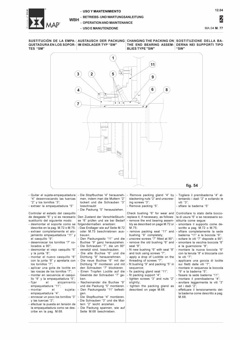
12.04
2
MA.04 M. 77
-
-
-
-
WBH
USO Y MANTENIMIENTO
BETRIEBS- UND WARTUNGSANLEITUNG
OPERATION AND MAINTENANCE
USO E MANUTENZIONE
SOSTITUZIONE DELLA BA-DERNA NEI SUPPORTI TIPO“SW”
AUSTAUSCH DER PACKUNGIM ENDLAGER TYP “SW”
CHANGING THE PACKING ONTHE END BEARING ASSEM-BLIES TYPE "SW"
SUSTITUCIÓN DE LA EMPA-QUETADURA EN LOS SOPOR-TES “SM”
- Togliere il premibaderna “4” al-lentando i dadi “2” e svitando leviti “3”;
- sfilare la baderna “5”
Controllare lo stato della bocco-la di usura “6” e se necessario so-stituirla come segue:- smontare il supporto come de-
scritto a pag. M.72 o M.75;- sfilare completamente la sede
baderna “11” e la boccola “9”;- svitare le viti “7” disposte a 90°;- smontare la vecchia boccola “6”
e la guarnizione “8”;- montare la nuova boccola “6”
con la tenuta “8” e bloccarla conle viti “7”;
- applicare una goccia di loctitesui filetti delle viti “7”;
- montare in sequenza la boccola“9” e la baderna “5”;
- fissare la sede baderna “11”;- montare il premibaderna “4”;- avvitare leggermente le viti “3”
ed i dadi “2”;- effettuare il tensionamento del-
la baderna come descritto a pag.M.68.
fig. 54
- Remove packing gland “4” byslackening nuts “2” and unscrew-ing screws “3”;
- Remove packing “5”.
Check bushing “6” for wear andreplace it, if necessary, as follows:- remove the end bearing assem-
bly as described on page M.72 orM.75;
- remove packing seat “11” andbushing “9” completely;
- unscrew screws “7” fitted at 90°;- remove the old bushing “6” and
seal “8”;- fit new bushing “6” with seal “8”
and lock using screws “7”;- apply a drop of Locktite on the
threading of screws “7”;- fit bushing “9” and packing “5” in
sequence;- fix packing gland seat “11”;- fit packing support “4”;- tighten screws “3” and nuts “2”
slightly;- tighten the packing gland as
described on page M.68.
- Die Stopfbuchse “4” herausneh-men, indem man die Muttern “2”lockert und die Schrauben “3”losschraubt
- Die Packung “5” herausziehen.
Den Zustand der Verschleißbuch-se “6” prüfen und sie bei Bedarffolgendermaßen ersetzen:- Das Endlager wie auf Seite M.72
oder M.75 beschriebnen aus-bauen.
- Den Packungssitz “11” und dieBuchse “9” ganz herausziehen.
- Die Schrauben “7”, die um 90°versetzt sind, losschrauben.
- Die alte Buchse “6” und dieDichtung “8” herausnehmen.
- Die neue Buchse “6” mit derDichtung “8” montieren und mitden Schrauben “7” blockieren.
- Einen Tropfen Loctite auf dieGewinde der Schrauben “7” ge-ben.
- Nacheinander die Buchse “9”und die Packung “5” montieren.
- Den Packungssitz “11” befesti-gen.
- Die Stopfbuchse “4” montieren.- Die Schrauben “3” und die Mut-
tern “2” leicht anziehen.- Die Packung spannen, wie auf
Seite M.68 beschrieben.
- Quitar el sujeta-empaquetadura“4” desenroscando las tuercas“2” y los tornillos “3”;
- extraer la empaquetadura “5”
Controlar el estado del casquillode desgaste “6” y si es necesariosustituirlo del siguiente modo:- desmontar el soporte como se
describe en la pag. M.72 o M.75;- extraer completamente el alo-
jamiento empaquetadura “11” yel casquillo “9”;
- desenroscar los tornillos “7” co-locados a 90°;
- desmontar el viejo casquillo “6”y la junta “8”;
- montar el nuevo casquillo “6”con la junta “8” y apretarla conlos tornillos “7”;
- aplicar una gota de loctite enlas roscas de los tornillos “7”;
- montar en secuencia el casqui-llo “9” y la empaquetadura “5”;
- fi jar el alojamientoempaquetadura “11”;
- montar el sujeta-empaquetadura “4”.
- enroscar un poco los tornillos “3”y las tuercas “2”;
- efectuar la puesta en tensión dela empaquetadura como se des-cribe en la pag. M.68.
1
•3
•4
•
2
•
11
•
7•
9
•
6
•
8
•
5
• • •
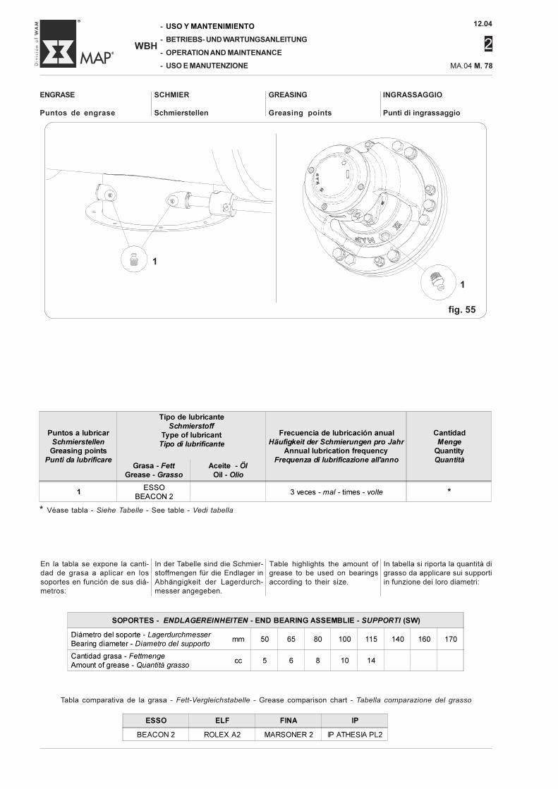
12.04
2
-
-
-
-
WBH
USO Y MANTENIMIENTO
BETRIEBS- UND WARTUNGSANLEITUNG
OPERATION AND MAINTENANCE
USO E MANUTENZIONE MA.04 M. 78
INGRASSAGGIO
Punti di ingrassaggio
ENGRASE
Puntos de engrase
SCHMIER
Schmierstellen
GREASING
Greasing points
* Véase tabla - Siehe Tabelle - See table - Vedi tabella
In tabella si riporta la quantità digrasso da applicare sui supportiin funzione dei loro diametri:
In der Tabelle sind die Schmier-stoffmengen für die Endlager inAbhängigkeit der Lagerdurch-messer angegeben.
Table highlights the amount ofgrease to be used on bearingsaccording to their size.
En la tabla se expone la canti-dad de grasa a aplicar en lossoportes en función de sus diá-metros:
Tabla comparativa de la grasa - Fett-Vergleichstabelle - Grease comparison chart - Tabella comparazione del grasso
fig. 55
Puntos a lubricar
SchmierstellenGreasing points
Punti da lubrificare
Tipo de lubricante
SchmierstoffType of lubricant
Tipo di lubrificante
Frecuencia de lubricación anual
Häufigkeit der Schmierungen pro JahrAnnual lubrication frequency
Frequenza di lubrificazione all'anno
Cantidad
MengeQuantity
QuantitàGrasa - Fett
Grease - GrassoAceite - Öl
Oil - Olio
1ESSO
BEACON 23 veces - mal - times - volte *
ESSO ELF FINA IP
BEACON 2 ROLEX A2 MARSONER 2 IP ATHESIA PL2
1
1
SOPORTES - ENDLAGEREINHEITEN - END BEARING ASSEMBLIE - SUPPORTI (SW)
Diámetro del soporte - Lagerdurchmesser
Bearing diameter - Diametro del supportomm 50 65 80 100 115 140 160 170
Cantidad grasa - Fettmenge
Amount of grease - Quantità grassocc 5 6 8 10 14
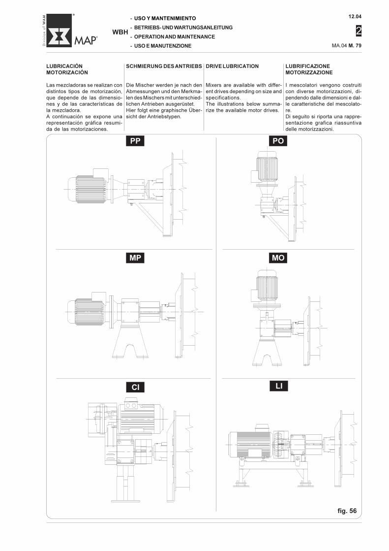
12.04
2
MA.04 M. 79
-
-
-
-
WBH
USO Y MANTENIMIENTO
BETRIEBS- UND WARTUNGSANLEITUNG
OPERATION AND MAINTENANCE
USO E MANUTENZIONE
LUBRIFICAZIONEMOTORIZZAZIONE
I mescolatori vengono costruiticon diverse motorizzazioni, di-pendendo dalle dimensioni e dal-le caratteristiche del mescolato-re.Di seguito si riporta una rappre-sentazione grafica riassuntivadelle motorizzazioni.
DRIVE LUBRICATION
Mixers are available with differ-ent drives depending on size andspecifications.The illustrations below summa-rize the available motor drives.
SCHMIERUNG DES ANTRIEBS
Die Mischer werden je nach denAbmessungen und den Merkma-len des Mischers mit unterschied-lichen Antrieben ausgerüstet.Hier folgt eine graphische Über-sicht der Antriebstypen.
LUBRICACIÓNMOTORIZACIÓN
Las mezcladoras se realizan condistintos tipos de motorización,que depende de las dimensio-nes y de las características dela mezcladora.A continuación se expone unarepresentación gráfica resumi-da de las motorizaciones.
fig. 56
PP PO
MP MO
LICI
12.04
2
-
-
-
-
WBH
USO Y MANTENIMIENTO
BETRIEBS- UND WARTUNGSANLEITUNG
OPERATION AND MAINTENANCE
USO E MANUTENZIONE MA.04 M. 80
Per la lubrificazione della moto-rizzazione seguire gli schemi diseguito riportati.
PP / POControllare il livello dell’olio nelriduttore, nel giunto idrodinamicoe se previsto ingrassare il moto-re elettrico (consultare i relativimanuali).
MP / MOControllare il livello olio nel ridut-tore e se previsto ingrassare ilmotore elettrico (consultare i re-lativi manuali). Periodicamente(una volta all’anno) controllare glielementi in gomma del giunto ela-stico.
CIControllare il livello dell’ olio nelriduttore, nel giunto idrodinamicoe se previsto ingrassare il moto-re elettrico (consultare i relativimanuali). Controllare il tensiona-mento e la misura delle cinghiedi trasmissione. Controllare glielementi in gomma del giunto ela-stico.
LIControllare il livello dell’olio nelriduttore, nel giunto idrodinamicoe se previsto ingrassare il moto-re elettrico (consultare i relativimanuali). Controllare gli elementiin gomma del giunto elastico so-lidale al giunto idrodinamico (vedimanuale istruzioni allegato).Provvedere alla sostituzione de-gli elementi in gomma almenouna volta all’anno.
Para la lubricación de la motori-zación seguir los esquemas ex-puestos a continuación.
PP / POControlar el nivel de aceite en elreductor, en el acoplamiento hi-drodinámico y si está previstoengrasar el motor eléctrico (con-sultar los respectivos manuales).
MP / MOControlar el nivel de aceite en elreductor y si está previsto en-grasar el motor eléctrico (con-sultar los respectivos manuales).Periódicamente (una vez al año)controlar los elementos de gomade la junta elástica.
CIControlar el nivel de aceite en elreductor, en acoplamiento hidro-dinámico y si está previsto en-grasar el motor eléctrico (con-sultar los respectivos manuales).Controlar la puesta en tensión yla medida de las correas detransmisión.Controlar los elementos de gomade la junta elástica.
LIControlar el nivel de aceite en elreductor, en acoplamiento hidro-dinámico y si está previsto en-grasar el motor eléctrico (con-sultar los respectivos manuales).Controlar los elementos de gomade la junta elástica que formaparte del acoplamiento hidrodi-námico (ver manual de instruc-ciones anexo).Efectuar la sustitución de los ele-mentos de goma por lo menosuna vez al año.
Zum Schmieren der Antriebe dieuntenstehenden Anleitungen be-achten.
PP / PODen Ölstand im Untersetzungs-getriebe, in der hydrodynami-schen Kupplung kontrollierenund, falls vorgesehen, den Elek-tromotor schmieren (siehe ent-sprechende anliegende Handbü-cher).
MP / MODen Ölstand im Untersetzungs-getriebe kontrollieren und, fallsvorgesehen, den Elektromotorschmieren (siehe entsprechendeanliegende Handbücher). Regel-mäßig (einmal pro Jahr) die Gum-mielemente der elastischenKupplung prüfen.
CIDen Ölstand im Untersetzungs-getriebe und in der hydrodynami-schen Kupplung kontrollierenund, falls vorgesehen, den Elek-tromotor schmieren (siehe ent-sprechende anliegende Handbü-cher). Die Spannung und die Grö-ße der Treibriemen prüfen. Re-gelmäßig die Gummielemente derelastischen Kupplung prüfen.
LIDen Ölstand im Untersetzungs-getriebe, in der hydrodynami-schen Kupplung kontrollierenund, falls vorgesehen, den Elek-tromotor schmieren (siehe ent-sprechende anliegende Handbü-cher). Die Gummielemente derelastischen Kupplung an der hy-drodynamischen Kupplung prü-fen (siehe Betriebsanleitung). DieGummielemente wenigstens ein-mal pro Jahr ersetzen.
Refer to the information belowfor details on drive lubrication.
PP / POCheck the oil level in the gearreducer, the hydraulic couplingand, if installed, grease the elec-tric motor (refer to the manual).
MP / MOCheck the oil level in the gearreducer and, if installed, greasethe electric motor (refer to themanual). From time to time (oncea year) check the rubber sec-tions of the flexible coupling.
CICheck the oil level in the gearreducer, the hydraulic couplingand, if installed, grease the elec-tric motor (refer to the manual).Check drive belt tensioning andsize. Check the rubber sectionsof the flexible coupling.
LICheck the oil level in the gearreducer, the hydraulic couplingand, if installed, grease the elec-tric motor (refer to the manual).Check the rubber elements in theflexible coupling “en bloc” withhydraulic coupling (see instruc-tion manual annexed). Replacethe rubber elements at least oncea year.
12.04
2
MA.04 M. 81
-
-
-
-
WBH
USO Y MANTENIMIENTO
BETRIEBS- UND WARTUNGSANLEITUNG
OPERATION AND MAINTENANCE
USO E MANUTENZIONE
SCHEDULED OVERHAUL
It is good standard operating prac-tice, especially with mixers sub-jected to very intense work, toschedule regular overhauls timedto match up with normal plantdowntimes.This kind of overhaul envisagesa careful and thorough visualand instrument checkout (asneeded) for all parts subject towear.In particular, it is very important toreplace all rubber parts (seals)on hatches, loading and dis-charge doors and flexible cou-plings.It is equally important to change(follow the procedures illustrat-ed in pag. M. 57), all parts espe-cially subject to wear and tear.Since part wear is largely in re-lation to the intensity of machinework, in addition to careful main-tenance and lubricating, it will beimportant for the operator to as-sess the replacement needs andschedule them accordingly.To reduce maintenance worktime, if the mixer is accidentallyshut down (a non-scheduledstop), we recommend keep thefollowing parts in stock.
1 Kit of mixing tools1 End bearing - motor side1 End bearing - opposite motor
side1 Pneumatic actuator1 Solenoid1 Solenoid coil1 Electromagnetic key operated
door lock2 End bearing shaft seals- Inspection hatch seal- discharge door seal (when en-
visaged)1 Kit flexible coupling rubber ele-
ments (where installed)1 Lit hydraulic coupling rubber
elements (where installed)1 Hydraulic coupling fuse plug1 Drive belt kit (where installed)1 Chopper assembly (where in-
stalled)1 Chopper tool kit (where in-
stalled)
lt is best, however, whenordering the mixer, ask forManufacturer to supply therecommended spare partsfor the precise mixer or-dered.
REVISIONE PROGRAMMATA
E’ opportuno, specialmente per imescolatori che operano in modointensivo, programmare periodi-ci interventi di revisione coinci-dente con i periodi di fermatadell’impianto.La revisione prevede un attentoe preciso controllo visivo e construmenti di controllo (se neces-sario) di tutte le parti soggette adusura.In particolare è indispensabile in-tervenire su tutte le parti in gom-ma (guarnizioni) dei portelli, del-le bocche di carico e dei giuntielastici. E’ altrettanto importantesostituire (seguendo quanto de-scritto a pag. M. 57) i particolariritenuti particolarmente soggettiad usura.Poiché l’usura dei particolari è inrelazione al lavoro più o menointensivo della macchina, ad unaaccurata manutenzione e lubrifi-cazione, diventa importante lavalutazione dell’utilizzatore suitempi di sostituzione di tali parti-colari. Per ridurre i tempi di inter-vento, in caso di arresto acciden-tale (fuori programma) del me-scolatore, Vi consigliamo di tene-re pronti a magazzino i seguentiricambi.
1 Kit utensili per la mescolazione1 Supporto d’estremità lato moto-
re1 Supporto d’estremità lato oppo-
sto al motore1 Attuatore pneumatico1 Elettrovalvola1 Bobina elettrovalvola1 Bloccaggio a chiave con elet-
tromagnete2 Tenute supporti- Guarnizione portelli ispezione- Guarnizione bocca di scarico
(quando prevista)1 Kit elementi in gomma del giunto
elastico (quando previsto)1 Kit elementi in gomma del giunto
idrodinamico (quando previsto)1 Tappo fusibile giunto idrodina-
mico1 Kit cinghie di trasmissione
(quando previste)1 Agitatore completo (quando
previsto)1 Kit utensili agitatori (quando
previsti)
E’ opportuno però, in fase diordine del mescolatore, ri-chiedere al costruttore i ri-cambi consigliati del propriomescolatore.
PROGRAMMIERTE ÜBERHO-LUNGBesonders für solche Mischer, dieintensiv arbeiten müssen, sollteman die Überholung für den Zeit-punkt einplanen, der mit einerAnlagenüberholung zusammen-fällt.Die Überholung sieht eine auf-merksame und genaue Kontrollealler Verschleißteile vor.Besonders wichtig ist die Kon-trolle aller Gummiteile (Dichtun-gen) der Klappen, der Beschi-ckungsstutzen und der elasti-schen Kupplungen.Ebenso wichtig ist der Austausch(siehe Abschnitt M.57 beschrie-benen Kriterien) der Teile, die ei-nem besonderen Verschleiß aus-gesetzt sind.Da der Verschleiß von der mehroder weniger großen Arbeitsbe-anspruchung der Maschine undder sorgfältigen Wartung undSchmierung abhängt, kommt derBeurteilung des Betreibershinsichtlich der Zeitintervalle zumAustausch dieser Teile eine gro-ße Bedeutung zu.Um die Abschaltzeiten, die füretwaige Reparaturen erforderlichsind, falls der Mischer unvorher-gesehen ausfällt (außerhalb desWartungsplans) zu verkürzen,sollten folgende Ersatzteile stetslagerhaltig beim Betreiber sein:
1 Satz Mischwerkzeuge1 antriebsseitige Endlagereinheit1 abtriebsseitige Endlagereinheit1 Druckluftzylinder1 Pneumaticantrieb1 Spule für Magnetventil1 Inspektionsklappenverriege-
lung mit Elektromagnet2 Endlagerdichtungen- Dichtung der Inspektionsklap-
pen- Dichtung der Auslaufklappe
(falls vorhanden)1 Satz Gummielemente für die
elastische Kupplung (falls vor-handen)
1 Satz Gummielemente für die hy-draulische Kupplung
1 Stopfen der Sicherung der hy-draulischen Kupplung
1 Satz Treibriemen (falls vorge-sehen)
1 kompletter Messerkopf (fallsvorhanden)
1 Satz Werkzeuge für Messerkopf(falls vorhanden)
Es empfiehlt sich jedoch, denHersteller beim Bestellen desMischers um eine Liste der Er-satzteile zu bitten, die er fürseinen Mischer empfiehlt.
REVISIÓN PROGRAMADA
Es oportuno, especialmente paralas mezcladoras que trabajanintensivamente, programar inter-venciones periódicas de revi-sión que coincidan con los pe-riodos de parada del equipo.La revisión prevé un atento ypreciso control visual y con ins-trumentos de control (si es ne-cesario) de todas las partes su-jetas a desgaste.En especial es indispensable in-tervenir en todas las partes degoma (juntas) de los registros,de las bocas de carga y de lasjuntas elásticas.Es muy importante también sus-tituir (siguiendo lo descrito en lapag. M. 57) las piezas que su-fren mucho desgaste.Visto que el desgaste de las pie-zas está en relación con el tra-bajo más o menos intensivo dela máquina, con un atento man-tenimiento y con la lubricación,se hace importante la evaluacióndel usuario sobre los tiempos desustitución de dichos particula-res.Para reducir los tiempos de in-tervención, en caso de paradaaccidental (fuera de programa)de la mezcladora, aconsejamostener listos en depósito los si-guientes repuestos.
1 Kit útiles para el mezclado1 Soporte de extremidad lado
motor1 Soporte de extremidad lado
opuesto motor1 Actuador neumático1 Electroválvula1 Bobina electroválvula1 Bloqueo puerta de llave con
electroimán2 Juntas soportes- Junta registros de inspección- Junta boca de descarga (si
está prevista)1 Kit elementos de goma de la
junta elástica (si está previs-ta)
1 Kit elementos de goma del aco-plamiento hidrodinámico (siestá previsto)
1 Tapón fusible acoplamientohidrodinámico
1 Kit correas de transmisión (siestán previstas)
1 Agitador completo (si está pre-visto)
1 Kit útiles agitadores (si estánprevistos)
Es oportuno, en fase de pe-dido de la mezcladora, soli-citar al fabricante los re-puestos aconsejados de lapropia mezcladora.
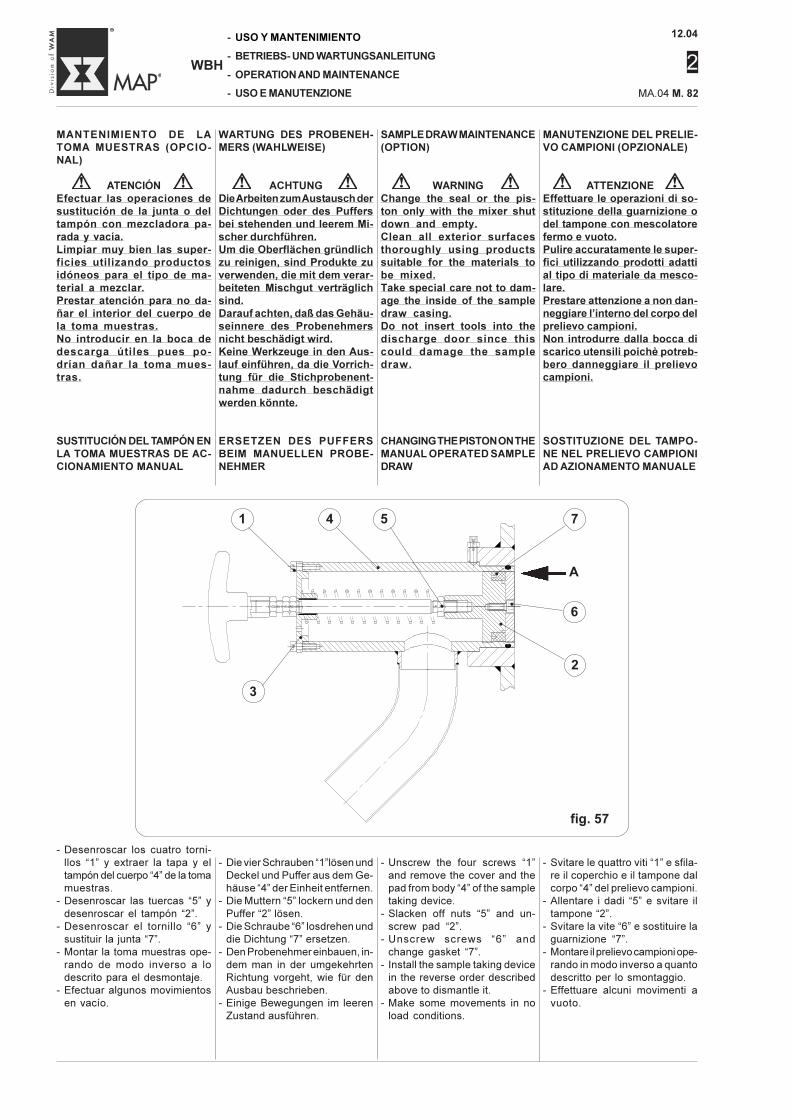
12.04
2
-
-
-
-
WBH
USO Y MANTENIMIENTO
BETRIEBS- UND WARTUNGSANLEITUNG
OPERATION AND MAINTENANCE
USO E MANUTENZIONE MA.04 M. 82
MANTENIMIENTO DE LATOMA MUESTRAS (OPCIO-NAL)
ATENCIÓNEfectuar las operaciones desustitución de la junta o deltampón con mezcladora pa-rada y vacía.Limpiar muy bien las super-ficies utilizando productosidóneos para el tipo de ma-terial a mezclar.Prestar atención para no da-ñar el interior del cuerpo dela toma muestras.No introducir en la boca dedescarga útiles pues po-drían dañar la toma mues-tras.
SUSTITUCIÓN DEL TAMPÓN ENLA TOMA MUESTRAS DE AC-CIONAMIENTO MANUAL
MANUTENZIONE DEL PRELIE-VO CAMPIONI (OPZIONALE)
ATTENZIONEEffettuare le operazioni di so-stituzione della guarnizione odel tampone con mescolatorefermo e vuoto.Pulire accuratamente le super-fici utilizzando prodotti adattial tipo di materiale da mesco-lare.Prestare attenzione a non dan-neggiare l’interno del corpo delprelievo campioni.Non introdurre dalla bocca discarico utensili poichè potreb-bero danneggiare il prelievocampioni.
SOSTITUZIONE DEL TAMPO-NE NEL PRELIEVO CAMPIONIAD AZIONAMENTO MANUALE
- Svitare le quattro viti “1” e sfila-re il coperchio e il tampone dalcorpo “4” del prelievo campioni.
- Allentare i dadi “5” e svitare iltampone “2”.
- Svitare la vite “6” e sostituire laguarnizione “7”.
- Montare il prelievo campioni ope-rando in modo inverso a quantodescritto per lo smontaggio.
- Effettuare alcuni movimenti avuoto.
- Desenroscar los cuatro torni-llos “1” y extraer la tapa y eltampón del cuerpo “4” de la tomamuestras.
- Desenroscar las tuercas “5” ydesenroscar el tampón “2”.
- Desenroscar el tornillo “6” ysustituir la junta “7”.
- Montar la toma muestras ope-rando de modo inverso a lodescrito para el desmontaje.
- Efectuar algunos movimientosen vacío.
WARTUNG DES PROBENEH-MERS (WAHLWEISE)
ACHTUNGDie Arbeiten zum Austausch derDichtungen oder des Puffersbei stehenden und leerem Mi-scher durchführen.Um die Oberflächen gründlichzu reinigen, sind Produkte zuverwenden, die mit dem verar-beiteten Mischgut verträglichsind.Darauf achten, daß das Gehäu-seinnere des Probenehmersnicht beschädigt wird.Keine Werkzeuge in den Aus-lauf einführen, da die Vorrich-tung für die Stichprobenent-nahme dadurch beschädigtwerden könnte.
ERSETZEN DES PUFFERSBEIM MANUELLEN PROBE-NEHMER
- Die vier Schrauben “1”lösen undDeckel und Puffer aus dem Ge-häuse “4” der Einheit entfernen.
- Die Muttern “5” lockern und denPuffer “2” lösen.
- Die Schraube “6” losdrehen unddie Dichtung “7” ersetzen.
- Den Probenehmer einbauen, in-dem man in der umgekehrtenRichtung vorgeht, wie für denAusbau beschrieben.
- Einige Bewegungen im leerenZustand ausführen.
SAMPLE DRAW MAINTENANCE(OPTION)
WARNINGChange the seal or the pis-ton only with the mixer shutdown and empty.Clean all exterior surfacesthoroughly using productssuitable for the materials tobe mixed.Take special care not to dam-age the inside of the sampledraw casing.Do not insert tools into thedischarge door since thiscould damage the sampledraw.
CHANGING THE PISTON ON THEMANUAL OPERATED SAMPLEDRAW
- Unscrew the four screws “1”and remove the cover and thepad from body “4” of the sampletaking device.
- Slacken off nuts “5” and un-screw pad “2”.
- Unscrew screws “6” andchange gasket “7”.
- Install the sample taking devicein the reverse order describedabove to dismantle it.
- Make some movements in noload conditions.
fig. 57
7
•
1
•
4
•
5
•
3
•
2
•6
•
A
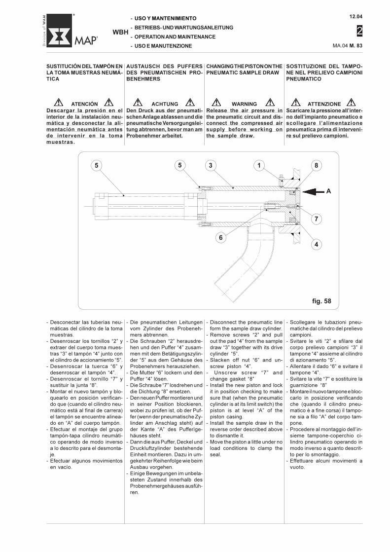
12.04
2
MA.04 M. 83
-
-
-
-
WBH
USO Y MANTENIMIENTO
BETRIEBS- UND WARTUNGSANLEITUNG
OPERATION AND MAINTENANCE
USO E MANUTENZIONE
SOSTITUZIONE DEL TAMPO-NE NEL PRELIEVO CAMPIONIPNEUMATICO
ATTENZIONEScaricare la pressione all’inter-no dell’impianto pneumatico escollegare l’alimentazionepneumatica prima di interveni-re sul prelievo campioni.
SUSTITUCIÓN DEL TAMPÓN ENLA TOMA MUESTRAS NEUMÁ-TICA
ATENCIÓNDescargar la presión en elinterior de la instalación neu-mática y desconectar la ali-mentación neumática antesde intervenir en la tomamuestras.
- Scollegare le tubazioni pneu-matiche dal cilindro del prelievocampioni.
- Svitare le viti “2” e sfilare dalcorpo prelievo campioni “3” iltampone “4” assieme al cilindrodi azionamento “5”.
- Allentare il dado “6” e svitare iltampone “4”.
- Svitare la vite “7” e sostituire laguarnizione “8”
- Montare il nuovo tampone e bloc-carlo in posizione verificandoche (quando il cilindro pneu-matico è a fine corsa) il tampo-ne sia a filo “A” del corpo tam-pone.
- Procedere al montaggio dell’in-sieme tampone-coperchio ci-lindro pneumatico operando inmodo inverso a quanto descrit-to per lo smontaggio.
- Effettuare alcuni movimenti avuoto.
- Desconectar las tuberías neu-máticas del cilindro de la tomamuestras.
- Desenroscar los tornillos “2” yextraer del cuerpo toma mues-tras “3” el tampón “4” junto conel cilindro de accionamiento “5”.
- Desenroscar la tuerca “6” ydesenroscar el tampón “4”.
- Desenroscar el tornillo “7” ysustituir la junta “8”.
- Montar el nuevo tampón y blo-quearlo en posición verifican-do que (cuando el cilindro neu-mático está al final de carrera)el tampón se encuentre alinea-do en “A” del cuerpo tampón.
- Efectuar el montaje del grupotampón-tapa cilindro neumáti-co operando de modo inversoa lo descrito para el desmonta-je.
- Efectuar algunos movimientosen vacío.
AUSTAUSCH DES PUFFERSDES PNEUMATISCHEN PRO-BENEHMERS
ACHTUNGDen Druck aus der pneumati-schen Anlage ablassen und diepneumatische Versorgungslei-tung abtrennen, bevor man amProbenehmer arbeitet.
- Die pneumatischen Leitungenvom Zylinder des Probeneh-mers abtrennen.
- Die Schrauben “2” herausdre-hen und den Puffer “4” zusam-men mit dem Betätigungszylin-der “5” aus dem Gehäuse desProbenehmers herausziehen.
- Die Mutter “6” lockern und denPuffer “4” lösen.
- Die Schraube “7” losdrehen unddie Dichtung “8” ersetzen.
- Den neuen Puffer montieren undin seiner Position blockieren,wobei zu prüfen ist, ob der Puf-fer (wenn der pneumatische Zy-linder am Anschlag steht) aufder Kante “A” des Pufferìge-häuses steht.
- Dann die aus Puffer, Deckel undDruckluftzylinder bestehendeEinheit montieren. Dazu in um-gekehrter Reihenfolge wie beimAusbau vorgehen.
- Einige Bewegungen im unbela-steten Zustand innerhalb desProbenehmergehäuses ausfüh-ren.
CHANGING THE PISTON ON THEPNEUMATIC SAMPLE DRAW
WARNINGRelease the air pressure inthe pneumatic circuit and dis-connect the compressed airsupply before working onthe sample draw.
- Disconnect the pneumatic lineform the sample draw cylinder.
- Remove screws “2” and pullout the pad “4” from the sampledraw “3” together with its drivecylinder “5”.
- Slacken off nut “6” and un-screw piston “4”.
- Unscrew screw “7” andchange gasket “8”
- Install the new piston and lockit in position checking to makesure that (when the pneumaticcylinder is at its limit switch) thepiston is at level “A” of thepiston casing.
- Install the sample draw in thereverse order described aboveto dismantle it.
- Move the piston a little under noload conditions to clamp theseal.
fig. 58
A
5
•
3
•
6
•
1
•
8
•
7
•
4
•
5
•
12.04
2
-
-
-
-
WBH
USO Y MANTENIMIENTO
BETRIEBS- UND WARTUNGSANLEITUNG
OPERATION AND MAINTENANCE
USO E MANUTENZIONE MA.04 M. 84
PULIZIA DELL’UGELLO NELDISPOSITIVO DI ATTIVAZIONELIQUIDI DALLA BOCCA DI CA-RICO E DELLA LANCIA INIE-ZIONE LIQUIDI
ATTENZIONEUsare detergenti o disincro-stanti atossici e non infiamma-bili.Utilizzando l’aria compressaservirsi di occhiali antinfortu-nistici per proteggersi dalleparticelle solide lanciate dalgetto d’aria.Limitare la pressione dell’ariaa 2 bar.
Smontare il dispositivo iniezioneliquidi e immergerlo per il temponecessario in una soluzione di-sincrostante.Pulire con un getto d’aria com-pressa o se necessario sostitui-re l’ugello.
NotaL’ugello deve essere sostituitocon uno nuovo dalle identichecaratteristiche e dello stesso tipodi materiale.
LIMPIEZA DE LA BOQUILLA ENEL DISPOSITIVO DE ADITIVA-CIÓN LÍQUIDOS POR LA BOCADE CARGA Y DE LA LANZA DEINYECCIÓN LÍQUIDOS
ATENCIÓNUsar detergentes o desin-crustantes no tóxicos y noinflamables.Utilizando aire comprimidoutilizar gafas de protecciónpara protegerse de las par-tículas sólidas lanzadas porel chorro de aire.Limitar la presión del aire a2 bar.
Desmontar el dispositivo de in-yección líquidos y sumergirlodurante el tiempo necesario enuna solución desincrustante.Limpiar con un chorro de airecomprimido o si es necesariosustituir la boquilla.
NotaLa boquilla se debe sustituir conuna nueva de idénticas carac-terísticas y del mismo tipo dematerial.
REINIGUNG DER ANSAUGDÜ-SEN DER VORRICHTUNG ZURFLÜSSIGKEITSZUGABE IMEINLAUF
ACHTUNGNur ungiftige und nicht feuer-gefährliche Reinigungs- undEntzunderungsmittel verwen-den.Bei der Benutzung von Druck-luft ist eine Schutzbrille zu tra-gen, um die Augen vor festenTeilchen zu schützen, die vonder Druckluft wirbelt werdenkönnten.Den Druck auf einen Wert vonmax. 2 bar beschränken.
Die Flüssigkeitszugabevorrich-tung ausbauen und solange wieerforderlich in das Entzunde-rungsmittel legen.Mit dem Druckluftstrahl reinigenund ggfls. die Düse ersetzen.
HinweisDie Düse muß durch eine neueDüse des gleichen Typs und ausdem gleichen Werkstoff ersetztwerden.
CLEANING PROCEDURE FORTHE LIQUID INJECTION SUC-TION NOZZLE FROM THE INLETLIQUID INJECTION LANCE
WARNINGUse non-toxic and non-flam-mable detergents or descal-ers.If you use compressed air toclean the machine, wear ac-cident prevention goggles toprotect your eyes from thesolid particulate matter pro-jected by the air jet.Limit the air pressure to 2bar.
Remove the liquid injection de-vice and immerse it for the timerequired in a scale removing so-lution.Clean the nozzle with a jet ofcompressed air or, as needed,change it.
NoteReplace the nozzle with anotherwith exactly the same specifica-tions as the old one and madefrom the same material.
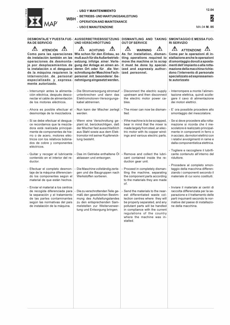
12.04
2
MA.04 M. 85
-
-
-
-
WBH
USO Y MANTENIMIENTO
BETRIEBS- UND WARTUNGSANLEITUNG
OPERATION AND MAINTENANCE
USO E MANUTENZIONE
DESMONTAJE Y PUESTA FUE-RA DE SERVICIO
ATENCIÓNComo para las operacionesde instalación también en lasoperaciones de desmonta-je por desplazamientos dela instalación o el desguacede la máquina requieren laintervención de personalespecializado y expresa-mente autorizado.
- Interrumpir antes la alimenta-ción eléctrica, después desco-nectar el cable de alimentaciónde los motores eléctricos.
- Ahora es posible efectuar eldesmontaje de la mezcladora.
- Si se debe efectuar el desgua-ce recordamos que la mezcla-dora está realizada principal-mente de componentes de hie-rro o de acero, motores eléc-tricos con los relativos bobina-dos de cobre y componenteseléctricos.
- Quitar y recoger el lubricantecontenido en el interior del re-ductor.
- Efectuar el completo desmon-taje de la máquina diferencian-do los componentes según elmaterial de que están hechos.
- Enviar el material a los centrosde recogida diferenciada parala separación y el tratamientode las partes contaminantessegún las normativas del paísde instalación de la máquina.
AUSSERBETRIEBSSETZUNGUND VERSCHROTTUNG
ACHTUNGWie schon für den Einbau, somuß auch für die Außerbetrieb-setzung infolge einer Verle-gung der Anlage an einen an-deren Ort oder für die Ver-schrottung der Maschine Fach-personal mit besonderer Ge-nehmigung eingesetzt werden.
- Die Stromversorgung stromaufunterbrechen und dann dasElektromotoren-Versorgungs-kabel abtrennen.
- Nun kann der Mischer zerlegtwerden.
- Wenn eine Verschrottung ge-plant ist, berücksichtigen, daßder Mischer fast ausschließlichaus Stahl sowie aus dem Elek-tromotor mit seiner Kupferwick-lung besteht.
- Das im Getriebe enthaltene Ölablassen und entsorgen.
- Die Maschine vollständig zerle-gen und die Baugruppen nachWerkstoffen sortieren.
- Die zu verschrottenden Teile ge-mäß den gesetzlichen Bestim-mung des Aufstellungslandeszu den entsprechenden Sam-melstellen zur Weiterverwer-tung und Entsorgung bringen.
DISMANTLING AND TAKINGOUT OF SERVICE
WARNINGAs for installation, disman-tling operations required tomove the machine or to scrapit must be done by special-ized and expressly author-ized personnel.
- Disconnect the electric supplyupstream and then disconnectthe electric motor power ca-bles.
- The mixer can now be disman-tled.
- If the machine is to be scrapped,bear in mind that the mixer ismade largely from steel, an elec-tric motor with its copper wind-ings and various electric parts.
- Remove and collect the lubri-cant contained inside the re-duction gear unit.
- Proceed in completely disman-tling the machine, separatingthe component parts accordingto the materials they are madeof.
- Send the materials to the near-est differentiated waste col-lection centres where they willbe properly separated, and anypollutant parts will be handledin compliance with the currentregulations of the countrywhere the machine was in-stalled.
SMONTAGGIO E MESSA FUO-RI SERVIZIO
ATTENZIONECome per le operazioni di in-stallazione anche le operazionidi smontaggio dovuti a sposta-menti dell’impianto o alla rotta-mazione della macchina richie-dono l’intervento di personalespecializzato ed espressamen-te autorizzato
- Interrompere a monte l’alimen-tazione elettrica, quindi scolle-gare il cavo di alimentazionedei motori elettrici.
- E’ ora possibile procedere allosmontaggio del mescolatore.
- Se si deve procedere alla rotta-mazione si ricorda che il me-scolatore è realizzato principal-mente in componenti in ferro oin acciaio, da motori elettrici coni relativi avvolgimenti in rame edalla componentistica elettrica.
- Togliere e raccogliere il lubrifi-cante contenuto all’interno delriduttore.
- Procedere al completo smon-taggio della macchina differen-ziando i componenti secondo ilmateriale di cui sono costituiti.
- Inviare il materiale ai centri diraccolta differenziata per la se-parazione e il trattamento delleparti inquinanti secondo le nor-mative del paese di installazio-ne della macchina.
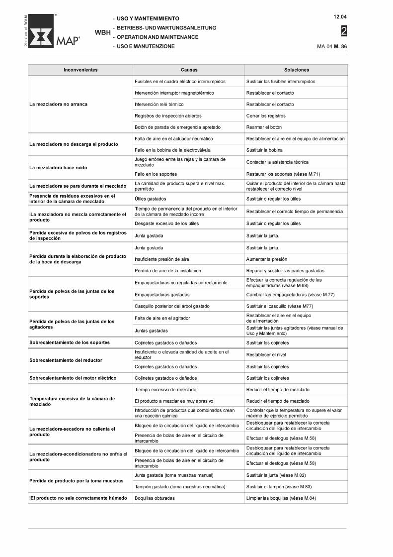
12.04
2
-
-
-
-
WBH
USO Y MANTENIMIENTO
BETRIEBS- UND WARTUNGSANLEITUNG
OPERATION AND MAINTENANCE
USO E MANUTENZIONE MA.04 M. 86
Inconvenientes Causas Soluciones
La mezcladora no arranca
Fusibles en el cuadro eléctrico interrumpidos Sustituir los fusibles interrumpidos
Intervención interruptor magnetotérmico Restablecer el contacto
Intervención relé térmico Restablecer el contacto
Registros de inspección abiertos Cerrar los registros
Botón de parada de emergencia apretado Rearmar el botón
La mezcladora no descarga el productoFalta de aire en el actuador neumático Restablecer el aire en el equipo de alimentación
Fallo en la bobina de la electroválvula Sustituir la bobina
La mezcladora hace ruido
Juego erróneo entre las rejas y la camara demezclado
Contactar la asistencia técnica
Fallo en los soportes Restaurar los soportes (véase M.71)
La mezcladora se para durante el mezcladoLa cantidad de producto supera e nivel max.permitido
Quitar el producto del interior de la cámara hastarestablecer el correcto nivel
Presencia de residuos excesivos en elinterior de la cámara de mezclado
Útiles gastados Sustituir o regular los útiles
ILa mezcladora no mezcla correctamente elproducto
Tiempo de permanencia del producto en el interiorde la cámara de mezclado incorre
Restablecer el correcto tiempo de permanencia
Desgaste excesivo de los útiles Sustituir o regular los útiles
Pérdida excesiva de polvos de los registrosde inspección
Junta gastada Sustituir la junta.
Pérdida durante la elaboración de productode la boca de descarga
Junta gastada Sustituir la junta.
Insuficiente presión de aire Aumentar la presión
Pérdida de aire de la instalación Reparar y sustituir las partes gastadas
Pérdida de polvos de las juntas de lossoportes
Empaquetaduras no reguladas correctamenteEfectuar la correcta regulación de lasempaquetaduras (véase M.68)
Empaquetaduras gastadas Cambiar las empaquetaduras (véase M.77)
Casquillo posterior del árbol gastado Sustituir el casquillo (véase M77)
Pérdida de polvos de las juntas de losagitadores
Falta de aire en el agitadorRestablecer el aire en el equipode alimentación
Juntas gastadasSustituir las juntas agitadores (véase manual deUso y Mantemiento)
Sobrecalentamiento de los soportes Cojinetes gastados o dañados Sustituir los cojinetes
Sobrecalentamiento del reductor
Insuficiente o elevada cantidad de aceite en elreductor
Restablecer el nivel
Cojinetes gastados o dañados Sustituir los cojinetes
Sobrecalentamiento del motor eléctrico Cojinetes gastados o dañados Sustituir los cojinetes
Temperatura excesiva de la cámara demezclado
Tiempo excesivo de mezclado Reducir el tiempo de mezclado
El producto a mezclar es muy abrasivo Reducir el tiempo de mezclado
Introducción de productos que combinados creanuna reacción química
Controlar que la temperatura no supere el valormáximo de ejercicio permitido
La mezcladora-secadora no calienta elproducto
Bloqueo de la circulación del líquido de intercambioDesbloquear para restablecer la correctacirculación del líquido de intercambio
Presencia de bolas de aire en el circuito deintercambio
Efectuar el desfogue (véase M.58)
La mezcladora-acondicionadora no enfría elproducto
Bloqueo de la circulación del líquido de intercambioDesbloquear para restablecer la correctacirculación del líquido de intercambio
Presencia de bolas de aire en el circuito deintercambio
Efectuar el desfogue (véase M.58)
Pérdida de producto por la toma muestrasJunta gastada (toma muestras manual) Sustituir la junta (véase M.82)
Tampón gastado (toma muestras neumática) Sustituir el tampón (véase M.83)
IEl producto no sale correctamente húmedo Boquillas obturadas Limpiar las boquillas (véase M.84)
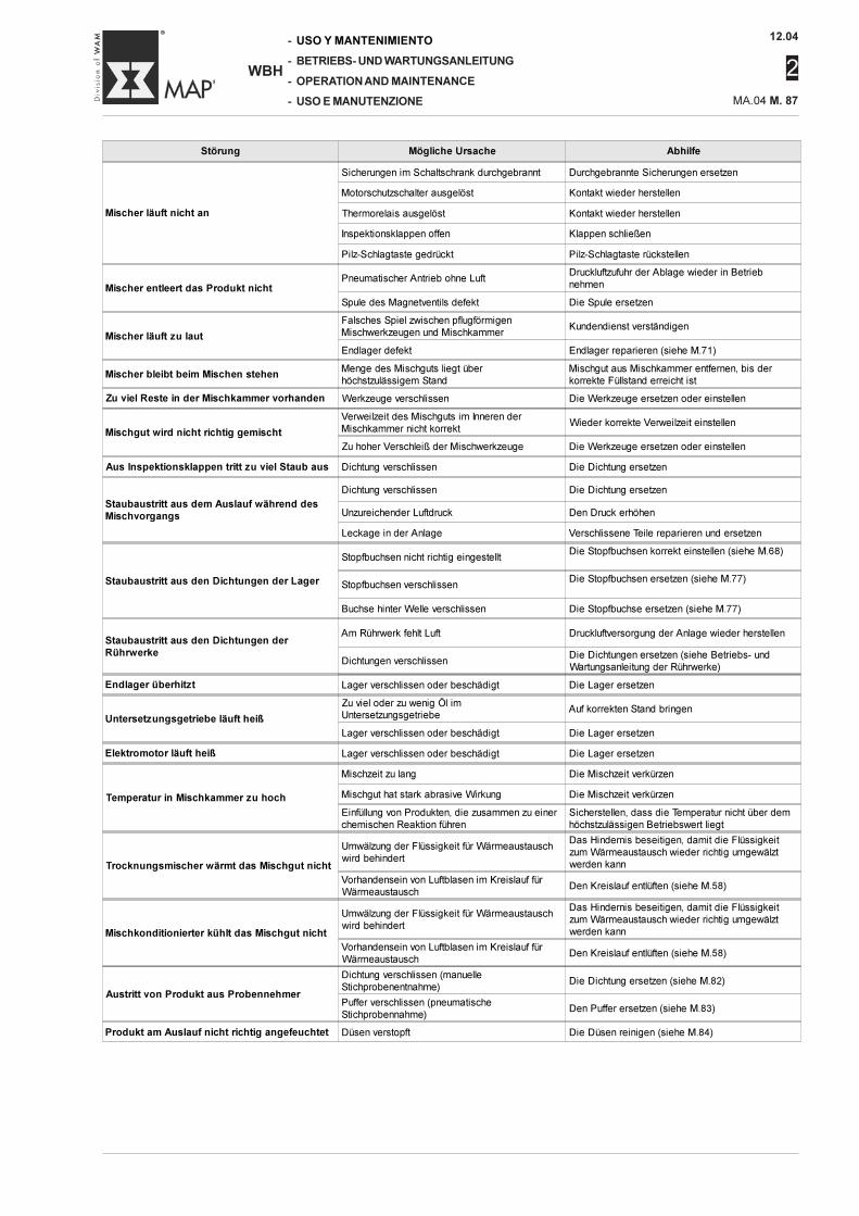
12.04
2
MA.04 M. 87
-
-
-
-
WBH
USO Y MANTENIMIENTO
BETRIEBS- UND WARTUNGSANLEITUNG
OPERATION AND MAINTENANCE
USO E MANUTENZIONE
Störung Mögliche Ursache Abhilfe
Mischer läuft nicht an
Sicherungen im Schaltschrank durchgebrannt Durchgebrannte Sicherungen ersetzen
Motorschutzschalter ausgelöst Kontakt wieder herstellen
Thermorelais ausgelöst Kontakt wieder herstellen
Inspektionsklappen offen Klappen schließen
Pilz-Schlagtaste gedrückt Pilz-Schlagtaste rückstellen
Mischer entleert das Produkt nichtPneumatischer Antrieb ohne Luft
Druckluftzufuhr der Ablage wieder in Betriebnehmen
Spule des Magnetventils defekt Die Spule ersetzen
Mischer läuft zu laut
Falsches Spiel zwischen pflugförmigenMischwerkzeugen und Mischkammer
Kundendienst verständigen
Endlager defekt Endlager reparieren (siehe M.71)
Mischer bleibt beim Mischen stehenMenge des Mischguts liegt überhöchstzulässigem Stand
Mischgut aus Mischkammer entfernen, bis derkorrekte Füllstand erreicht ist
Zu viel Reste in der Mischkammer vorhanden Werkzeuge verschlissen Die Werkzeuge ersetzen oder einstellen
Mischgut wird nicht richtig gemischt
Verweilzeit des Mischguts im Inneren derMischkammer nicht korrekt
Wieder korrekte Verweilzeit einstellen
Zu hoher Verschleiß der Mischwerkzeuge Die Werkzeuge ersetzen oder einstellen
Aus Inspektionsklappen tritt zu viel Staub aus Dichtung verschlissen Die Dichtung ersetzen
Staubaustritt aus dem Auslauf während desMischvorgangs
Dichtung verschlissen Die Dichtung ersetzen
Unzureichender Luftdruck Den Druck erhöhen
Leckage in der Anlage Verschlissene Teile reparieren und ersetzen
Staubaustritt aus den Dichtungen der Lager
Stopfbuchsen nicht richtig eingestelltDie Stopfbuchsen korrekt einstellen (siehe M.68)
Stopfbuchsen verschlissenDie Stopfbuchsen ersetzen (siehe M.77)
Buchse hinter Welle verschlissen Die Stopfbuchse ersetzen (siehe M.77)
Staubaustritt aus den Dichtungen derRührwerke
Am Rührwerk fehlt Luft Druckluftversorgung der Anlage wieder herstellen
Dichtungen verschlissenDie Dichtungen ersetzen (siehe Betriebs- undWartungsanleitung der Rührwerke)
Endlager überhitzt Lager verschlissen oder beschädigt Die Lager ersetzen
Untersetzungsgetriebe läuft heiß
Zu viel oder zu wenig Öl imUntersetzungsgetriebe
Auf korrekten Stand bringen
Lager verschlissen oder beschädigt Die Lager ersetzen
Elektromotor läuft heiß Lager verschlissen oder beschädigt Die Lager ersetzen
Temperatur in Mischkammer zu hoch
Mischzeit zu lang Die Mischzeit verkürzen
Mischgut hat stark abrasive Wirkung Die Mischzeit verkürzen
Einfüllung von Produkten, die zusammen zu einerchemischen Reaktion führen
Sicherstellen, dass die Temperatur nicht über demhöchstzulässigen Betriebswert liegt
Trocknungsmischer wärmt das Mischgut nicht
Umwälzung der Flüssigkeit für Wärmeaustauschwird behindert
Das Hindernis beseitigen, damit die Flüssigkeitzum Wärmeaustausch wieder richtig umgewälztwerden kann
Vorhandensein von Luftblasen im Kreislauf fürWärmeaustausch
Den Kreislauf entlüften (siehe M.58)
Mischkonditionierter kühlt das Mischgut nicht
Umwälzung der Flüssigkeit für Wärmeaustauschwird behindert
Das Hindernis beseitigen, damit die Flüssigkeitzum Wärmeaustausch wieder richtig umgewälztwerden kann
Vorhandensein von Luftblasen im Kreislauf fürWärmeaustausch
Den Kreislauf entlüften (siehe M.58)
Austritt von Produkt aus Probennehmer
Dichtung verschlissen (manuelleStichprobenentnahme)
Die Dichtung ersetzen (siehe M.82)
Puffer verschlissen (pneumatischeStichprobennahme)
Den Puffer ersetzen (siehe M.83)
Produkt am Auslauf nicht richtig angefeuchtet Düsen verstopft Die Düsen reinigen (siehe M.84)
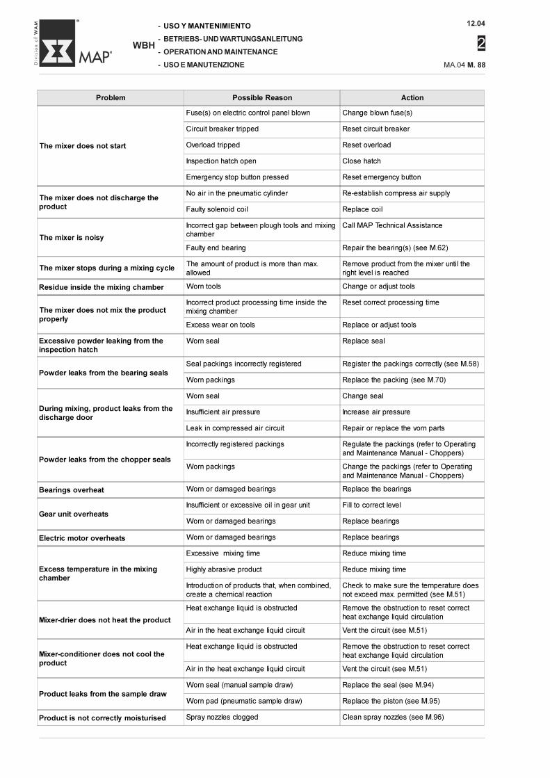
12.04
2
-
-
-
-
WBH
USO Y MANTENIMIENTO
BETRIEBS- UND WARTUNGSANLEITUNG
OPERATION AND MAINTENANCE
USO E MANUTENZIONE MA.04 M. 88
Problem Possible Reason Action
The mixer does not start
Fuse(s) on electric control panel blown Change blown fuse(s)
Circuit breaker tripped Reset circuit breaker
Overload tripped Reset overload
Inspection hatch open Close hatch
Emergency stop button pressed Reset emergency button
The mixer does not discharge the
product
No air in the pneumatic cylinder Re-establish compress air supply
Faulty solenoid coil Replace coil
The mixer is noisy
Incorrect gap between plough tools and mixing
chamber
Call MAP Technical Assistance
Faulty end bearing Repair the bearing(s) (see M.62)
The mixer stops during a mixing cycleThe amount of product is more than max.
allowed
Remove product from the mixer until the
right level is reached
Residue inside the mixing chamber Worn tools Change or adjust tools
The mixer does not mix the product
properly
Incorrect product processing time inside the
mixing chamber
Reset correct processing time
Excess wear on tools Replace or adjust tools
Excessive powder leaking from the
inspection hatch
Worn seal Replace seal
Powder leaks from the bearing seals
Seal packings incorrectly registered Register the packings correctly (see M.58)
Worn packings Replace the packing (see M.70)
During mixing, product leaks from the
discharge door
Worn seal Change seal
Insufficient air pressure Increase air pressure
Leak in compressed air circuit Repair or replace the vorn parts
Powder leaks from the chopper seals
Incorrectly registered packings Regulate the packings (refer to Operating
and Maintenance Manual - Choppers)
Worn packings Change the packings (refer to Operating
and Maintenance Manual - Choppers)
Bearings overheat Worn or damaged bearings Replace the bearings
Gear unit overheats
Insufficient or excessive oil in gear unit Fill to correct level
Worn or damaged bearings Replace bearings
Electric motor overheats Worn or damaged bearings Replace bearings
Excess temperature in the mixing
chamber
Excessive mixing time Reduce mixing time
Highly abrasive product Reduce mixing time
Introduction of products that, when combined,
create a chemical reaction
Check to make sure the temperature does
not exceed max. permitted (see M.51)
Mixer-drier does not heat the product
Heat exchange liquid is obstructed Remove the obstruction to reset correct
heat exchange liquid circulation
Air in the heat exchange liquid circuit Vent the circuit (see M.51)
Mixer-conditioner does not cool the
product
Heat exchange liquid is obstructed Remove the obstruction to reset correct
heat exchange liquid circulation
Air in the heat exchange liquid circuit Vent the circuit (see M.51)
Product leaks from the sample draw
Worn seal (manual sample draw) Replace the seal (see M.94)
Worn pad (pneumatic sample draw) Replace the piston (see M.95)
Product is not correctly moisturised Spray nozzles clogged Clean spray nozzles (see M.96)
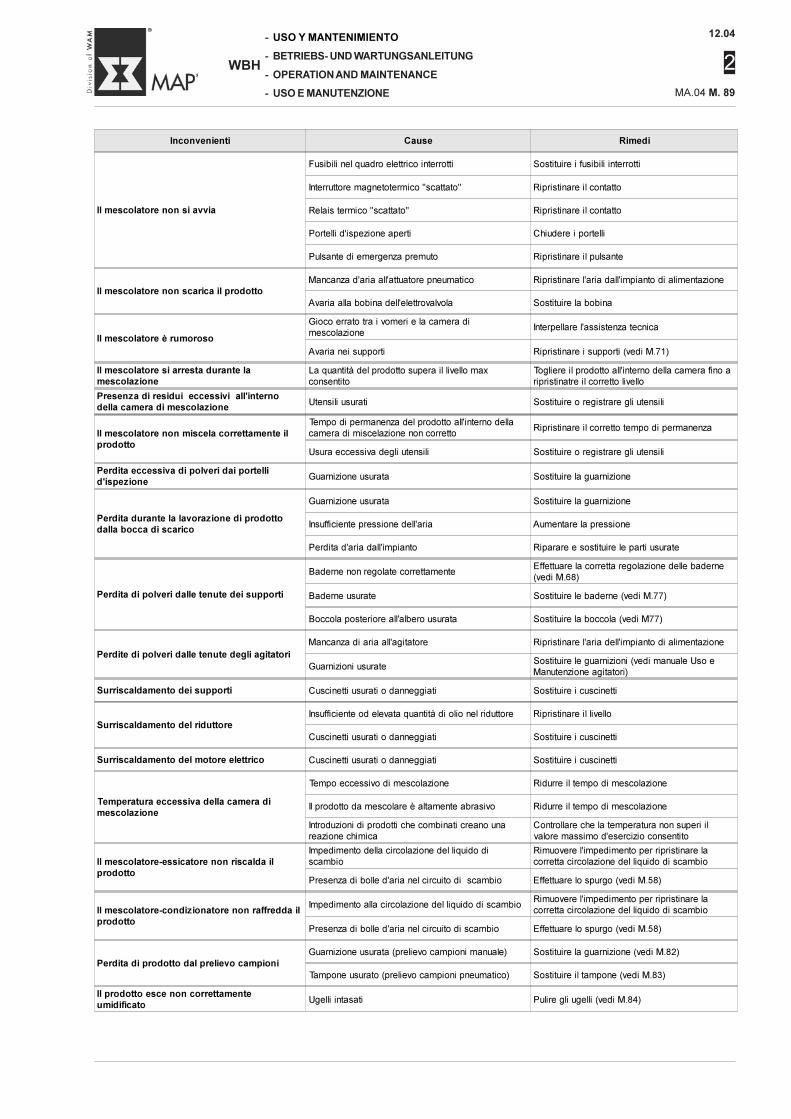
12.04
2
MA.04 M. 89
-
-
-
-
WBH
USO Y MANTENIMIENTO
BETRIEBS- UND WARTUNGSANLEITUNG
OPERATION AND MAINTENANCE
USO E MANUTENZIONE
Inconvenienti Cause Rimedi
Il mescolatore non si avvia
Fusibili nel quadro elettrico interrotti Sostituire i fusibili interrotti
Interruttore magnetotermico "scattato" Ripristinare il contatto
Relais termico "scattato" Ripristinare il contatto
Portelli d'ispezione aperti Chiudere i portelli
Pulsante di emergenza premuto Ripristinare il pulsante
Il mescolatore non scarica il prodottoMancanza d'aria all'attuatore pneumatico Ripristinare l'aria dall'impianto di alimentazione
Avaria alla bobina dell'elettrovalvola Sostituire la bobina
Il mescolatore è rumoroso
Gioco errato tra i vomeri e la camera di
mescolazioneInterpellare l'assistenza tecnica
Avaria nei supporti Ripristinare i supporti (vedi M.71)
Il mescolatore si arresta durante lamescolazione
La quantità del prodotto supera il livello max
consentito
Togliere il prodotto all'interno della camera fino a
ripristinatre il corretto livello
Presenza di residui eccessivi all'internodella camera di mescolazione
Utensili usurati Sostituire o registrare gli utensili
Il mescolatore non miscela correttamente ilprodotto
Tempo di permanenza del prodotto all'interno della
camera di miscelazione non correttoRipristinare il corretto tempo di permanenza
Usura eccessiva degli utensili Sostituire o registrare gli utensili
Perdita eccessiva di polveri dai portellid'ispezione
Guarnizione usurata Sostituire la guarnizione
Perdita durante la lavorazione di prodottodalla bocca di scarico
Guarnizione usurata Sostituire la guarnizione
Insufficiente pressione dell'aria Aumentare la pressione
Perdita d'aria dall'impianto Riparare e sostituire le parti usurate
Perdita di polveri dalle tenute dei supporti
Baderne non regolate correttamenteEffettuare la corretta regolazione delle baderne
(vedi M.68)
Baderne usurate Sostituire le baderne (vedi M.77)
Boccola posteriore all'albero usurata Sostituire la boccola (vedi M77)
Perdite di polveri dalle tenute degli agitatori
Mancanza di aria all'agitatore Ripristinare l'aria dell'impianto di alimentazione
Guarnizioni usurateSostituire le guarnizioni (vedi manuale Uso e
Manutenzione agitatori)
Surriscaldamento dei supporti Cuscinetti usurati o danneggiati Sostituire i cuscinetti
Surriscaldamento del riduttoreInsufficiente od elevata quantità di olio nel riduttore Ripristinare il livello
Cuscinetti usurati o danneggiati Sostituire i cuscinetti
Surriscaldamento del motore elettrico Cuscinetti usurati o danneggiati Sostituire i cuscinetti
Temperatura eccessiva della camera dimescolazione
Tempo eccessivo di mescolazione Ridurre il tempo di mescolazione
Il prodotto da mescolare è altamente abrasivo Ridurre il tempo di mescolazione
Introduzioni di prodotti che combinati creano una
reazione chimica
Controllare che la temperatura non superi il
valore massimo d'esercizio consentito
Il mescolatore-essicatore non riscalda ilprodotto
Impedimento della circolazione del liquido di
scambio
Rimuovere l'impedimento per ripristinare la
corretta circolazione del liquido di scambio
Presenza di bolle d'aria nel circuito di scambio Effettuare lo spurgo (vedi M.58)
Il mescolatore-condizionatore non raffredda ilprodotto
Impedimento alla circolazione del liquido di scambioRimuovere l'impedimento per ripristinare la
corretta circolazione del liquido di scambio
Presenza di bolle d'aria nel circuito di scambio Effettuare lo spurgo (vedi M.58)
Perdita di prodotto dal prelievo campioni
Guarnizione usurata (prelievo campioni manuale) Sostituire la guarnizione (vedi M.82)
Tampone usurato (prelievo campioni pneumatico) Sostituire il tampone (vedi M.83)
Il prodotto esce non correttamenteumidificato
Ugelli intasati Pulire gli ugelli (vedi M.84)

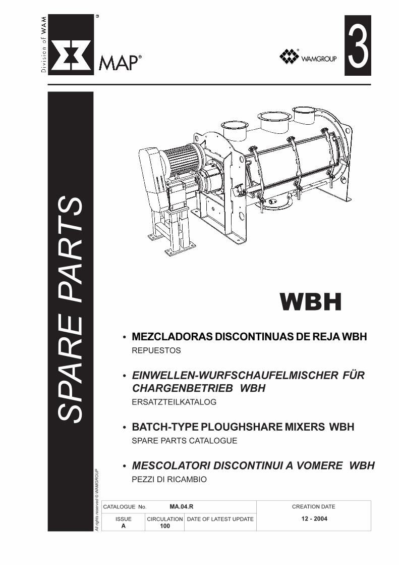
All
rights
rese
rved ©
WA
MG
RO
UP
WBH
CATALOGUE No. MA.04.R
ISSUEA
DATE OF LATEST UPDATE
CREATION DATE
CIRCULATION100
SP
AR
E P
AR
TS3
12 - 2004
• MEZCLADORAS DISCONTINUAS DE REJA WBH
REPUESTOS
• EINWELLEN-WURFSCHAUFELMISCHER FÜR
CHARGENBETRIEB WBH
ERSATZTEILKATALOG
• BATCH-TYPE PLOUGHSHARE MIXERS WBH
SPARE PARTS CATALOGUE
• MESCOLATORI DISCONTINUI A VOMERE WBH
PEZZI DI RICAMBIO

12.04
MA.04.INDEX
-
-
-
-
WBH
ÍNDICE
INHALTSVERZEICHNIS
INDEX
INDICE
2
M. 3 → 4M. 5 → 89
WARTUNGSKATALOGBETRIEBS- UND WARTUNGSANLEITUNG - EINFÜHRUNG......BETRIEBS- UND WARTUNGSANLEITUNG.................................
CATÁLOGO DE MANTENIMIENTOUSO Y MANTENIMIENTO - INTRODUCCIÓN .......................USO Y MANTENIMIENTO ....................................................
CATALOGO DI MANUTENZIONEUSO E MANUTENZIONE - INTRODUZIONE...............................USO E MANUTENZIONE..............................................................
MAINTENANCE CATALOGUEOPERATION AND MAINTENANCE - INTRODUCTION.........OPERATION AND MAINTENANCE........................................
2
3
R.93949596979899100101102
ERSATZTEILKATALOGMISCHERGEHÄUSE...............................................................INSPEKTIONSKLAPPE.............................................................RUNDER ALAUSLAUF..............................................................MANUELLER PROBENEHMER................................................PNEUMATISCHER PROBENEHMER.......................................PNEUMATISCHER ANTRIEB FÜR AUSLAUFKLAPPE............ROTORWELLE..........................................................................ENDLAGERWELLENABDICHTUNG.........................................ENDLAGEREINHEIT ANTRIEBSSEITIG...................................ENDLAGEREINHEIT ABTRIEBSSEITIG...................................
CATÁLOGO DE REPUESTOSCUERPO MEZCLADORA .........................................................REGISTRO DE INSPECCIÓN ....................................................BOCA DE DESCARGA REDONDA ..........................................TOMA MUESTRA MANUAL .....................................................TOMA MUESTRA NEUMÁTICA ................................................ACTUADOR NEUMÁTICO BOCA DESCARGA .......................ROTOR .....................................................................................CIERRE SOPORTE DE EXTREMIDAD ......................................SOPORTE PARA ÁRBOL LADO MOTORIZACIÓN .................SOPORTE ÁRBOL LADO OPUESTO MOTORIZACIÓN ..........
CATALOGO PEZZI DI RICAMBIOCORPO MESCOLATORE.......................................................PORTELLO D’ISPEZIONE........................................................BOCCA DI SCARICO TONDA...................................................PRELIEVO CAMPIONE MANUALE..........................................PRELIEVO CAMPIONE PNEUMATICO....................................ATTUATORE PNEUMATICO BOCCA SCARICO......................ROTORE ..................................................................................TENUTA SUPPORTO ESTREMITA’.........................................SUPPORTO PER ALBERO LATO MOTORIZZAZIONE...........SUPPORTO ALBERO LATO OPPOSTO MOTORIZZAZIONE.
SPARE PARTS CATALOGUEMIXING SHELL......................................................................INSPECTION DOOR..............................................................ROUND OUTLET...................................................................MANUAL SAMPLE DRAW.....................................................PNEUMATIC SAMPLE DRAW...............................................PNEUMATIC OUTLET ACTUATOR.....................................ROTOR..................................................................................SHAFT SEAL END BEARING ASSEMBLY............................END BEARING ASSEMBLY DRIVE END.............................END BEARING ASSEMBLY OPPOSITE DRIVE END..........
3
M. 3 → 4M. 5 → 89
R.93949596979899100101102
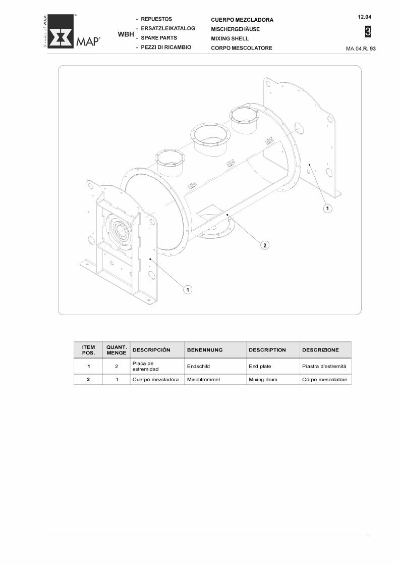
12.04
3
-
-
-
-
WBH
REPUESTOS
ERSATZLEIKATALOG
SPARE PARTS
PEZZI DI RICAMBIO MA.04.R. 93
CUERPO MEZCLADORA
MISCHERGEHÄUSE
MIXING SHELL
CORPO MESCOLATORE
ITEMPOS.
QUANT.MENGE
DESCRIPCIÓN BENENNUNG DESCRIPTION DESCRIZIONE
1 2Placa de
extremidadEndschild End plate Piastra d'estremità
2 1 Cuerpo mezcladora Mischtrommel Mixing drum Corpo mescolatore
1
•
2
•
1
•
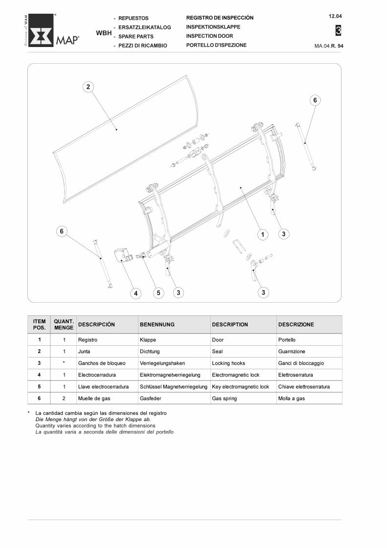
12.04
MA.04.R. 94
3
-
-
-
-
WBH
REPUESTOS
ERSATZLEIKATALOG
SPARE PARTS
PEZZI DI RICAMBIO
REGISTRO DE INSPECCIÓN
INSPEKTIONSKLAPPE
INSPECTION DOOR
PORTELLO D'ISPEZIONE
* La cantidad cambia según las dimensiones del registroDie Menge hängt von der Größe der Klappe ab.
Quantity varies according to the hatch dimensionsLa quantità varia a seconda delle dimensioni del portello
ITEMPOS.
QUANT.MENGE
DESCRIPCIÓN BENENNUNG DESCRIPTION DESCRIZIONE
1 1 Registro Klappe Door Portello
2 1 Junta Dichtung Seal Guarnizione
3 * Ganchos de bloqueo Verriegelungshaken Locking hooks Ganci di bloccaggio
4 1 Electrocerradura Elektromagnetverriegelung Electromagnetic lock Elettroserratura
5 1 Llave electrocerradura Schlüssel Magnetverriegelung Key electromagnetic lock Chiave elettroserratura
6 2 Muelle de gas Gasfeder Gas spring Molla a gas
2
•
6
•
4
•
5
•
1
•
3
•
3
•
3
•
6
•
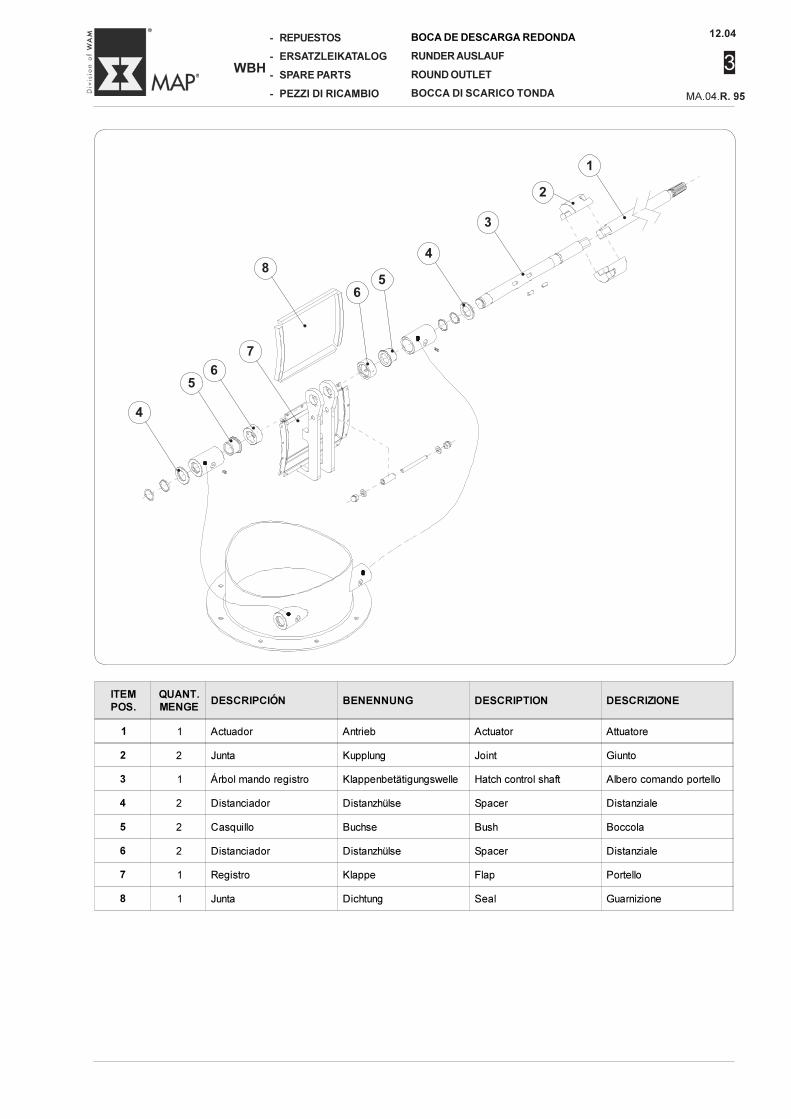
12.04
3
-
-
-
-
WBH
REPUESTOS
ERSATZLEIKATALOG
SPARE PARTS
PEZZI DI RICAMBIO MA.04.R. 95
BOCA DE DESCARGA REDONDA
RUNDER AUSLAUF
ROUND OUTLET
BOCCA DI SCARICO TONDA
ITEMPOS.
QUANT.MENGE
DESCRIPCIÓN BENENNUNG DESCRIPTION DESCRIZIONE
1 1 Actuador Antrieb Actuator Attuatore
2 2 Junta Kupplung Joint Giunto
3 1 Árbol mando registro Klappenbetätigungswelle Hatch control shaft Albero comando portello
4 2 Distanciador Distanzhülse Spacer Distanziale
5 2 Casquillo Buchse Bush Boccola
6 2 Distanciador Distanzhülse Spacer Distanziale
7 1 Registro Klappe Flap Portello
8 1 Junta Dichtung Seal Guarnizione
4
•
5
•
6
•
8
•
6
•
5
•
4
•
3
•
1
•
2•
7
•
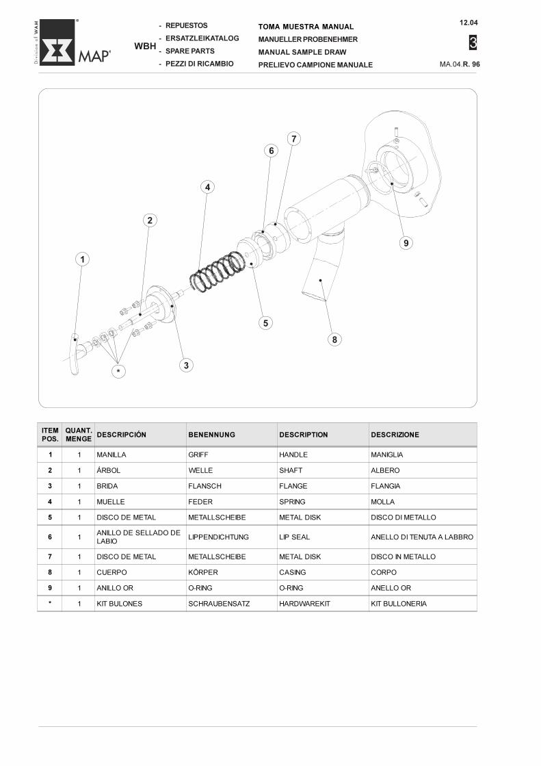
12.04
MA.04.R. 96
3
-
-
-
-
WBH
REPUESTOS
ERSATZLEIKATALOG
SPARE PARTS
PEZZI DI RICAMBIO
TOMA MUESTRA MANUAL
MANUELLER PROBENEHMER
MANUAL SAMPLE DRAW
PRELIEVO CAMPIONE MANUALE
ITEMPOS.
QUANT.MENGE
DESCRIPCIÓN BENENNUNG DESCRIPTION DESCRIZIONE
1 1 MANILLA GRIFF HANDLE MANIGLIA
2 1 ÁRBOL WELLE SHAFT ALBERO
3 1 BRIDA FLANSCH FLANGE FLANGIA
4 1 MUELLE FEDER SPRING MOLLA
5 1 DISCO DE METAL METALLSCHEIBE METAL DISK DISCO DI METALLO
6 1ANILLO DE SELLADO DE
LABIOLIPPENDICHTUNG LIP SEAL ANELLO DI TENUTA A LABBRO
7 1 DISCO DE METAL METALLSCHEIBE METAL DISK DISCO IN METALLO
8 1 CUERPO KÖRPER CASING CORPO
9 1 ANILLO OR O-RING O-RING ANELLO OR
* 1 KIT BULONES SCHRAUBENSATZ HARDWAREKIT KIT BULLONERIA
•
7
•
6
•
4
•
1
•
2
•
5
•
8
•
9
*
•
3
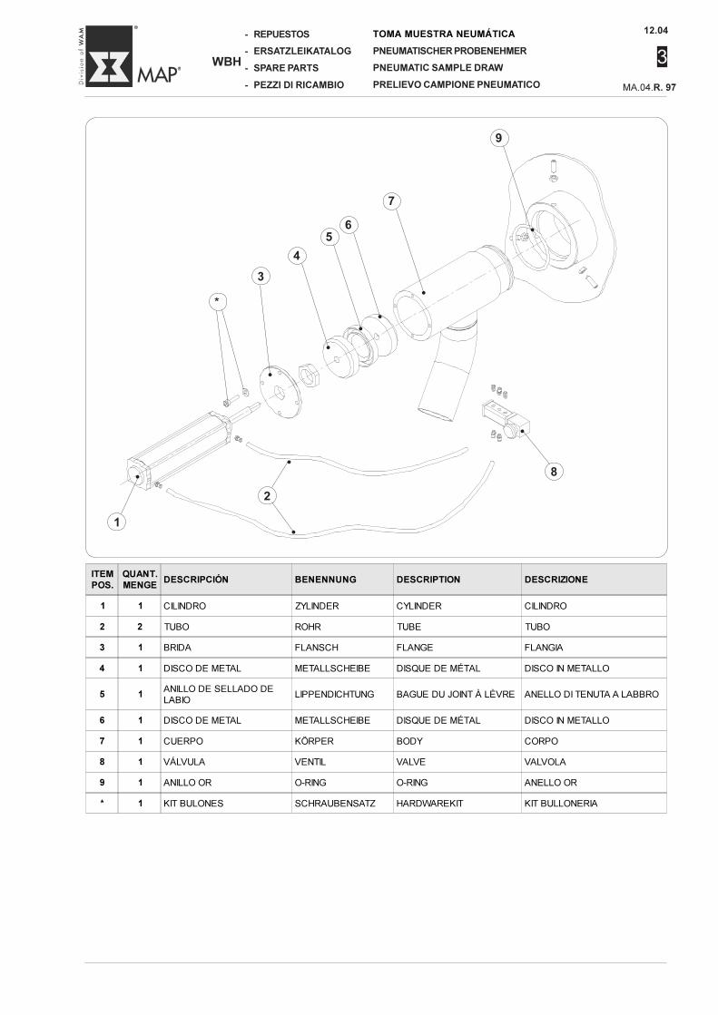
12.04
3
-
-
-
-
WBH
REPUESTOS
ERSATZLEIKATALOG
SPARE PARTS
PEZZI DI RICAMBIO MA.04.R. 97
TOMA MUESTRA NEUMÁTICA
PNEUMATISCHER PROBENEHMER
PNEUMATIC SAMPLE DRAW
PRELIEVO CAMPIONE PNEUMATICO
ITEMPOS.
QUANT.MENGE
DESCRIPCIÓN BENENNUNG DESCRIPTION DESCRIZIONE
1 1 CILINDRO ZYLINDER CYLINDER CILINDRO
2 2 TUBO ROHR TUBE TUBO
3 1 BRIDA FLANSCH FLANGE FLANGIA
4 1 DISCO DE METAL METALLSCHEIBE DISQUE DE MÉTAL DISCO IN METALLO
5 1ANILLO DE SELLADO DELABIO
LIPPENDICHTUNG BAGUE DU JOINT À LÈVRE ANELLO DI TENUTA A LABBRO
6 1 DISCO DE METAL METALLSCHEIBE DISQUE DE MÉTAL DISCO IN METALLO
7 1 CUERPO KÖRPER BODY CORPO
8 1 VÁLVULA VENTIL VALVE VALVOLA
9 1 ANILLO OR O-RING O-RING ANELLO OR
* 1 KIT BULONES SCHRAUBENSATZ HARDWAREKIT KIT BULLONERIA
•
3
*
•
1
•
2
•
•
8
•
4
•
5
•
6
•
7
•
9
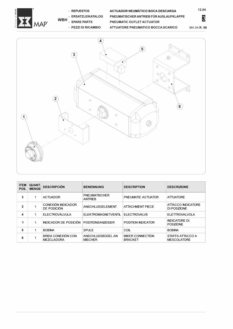
12.04
MA.04.R. 98
3
-
-
-
-
WBH
REPUESTOS
ERSATZLEIKATALOG
SPARE PARTS
PEZZI DI RICAMBIO
ACTUADOR NEUMÁTICO BOCA DESCARGA
PNEUMATISCHER ANTRIEB FÜR AUSLAUFKLAPPE
PNEUMATIC OUTLET ACTUATOR
ATTUATORE PNEUMATICO BOCCA SCARICO
•
1•
2
•
5
•
3 •
4
•
6
ITEMPOS.
QUANT.MENGE
DESCRIPCIÓN BENENNUNG DESCRIPTION DESCRIZIONE
3 1 ACTUADORPNEUMATISCHER
ANTRIEBPNEUMATIC ACTUATOR ATTUATORE
2 1CONEXIÓN INDICADOR
DE POSICIÓNANSCHLUSSELEMENT ATTACHMENT PIECE
ATTACCO INDICATORE
DI POSIZIONE
4 1 ELECTROVÁLVULA ELEKTROMAGNETVENTIL ELECTROVALVE ELETTROVALVOLA
1 1 INDICADOR DE POSICIÓN POSITIONSANZEIGER POSITION INDICATORINDICATORE DI
POSIZIONE
5 1 BOBINA SPULE COIL BOBINA
6 1BRIDA CONEXIÓN CON
MEZCLADORA
ANSCHLUSSBÜGEL AN
MISCHER
MIXER CONNECTION
BRACKET
STAFFA ATTACCO A
MESCOLATORE
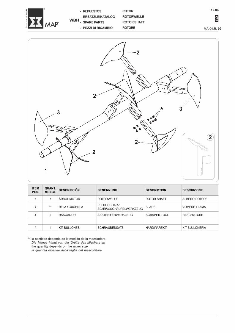
12.04
3
-
-
-
-
WBH
REPUESTOS
ERSATZLEIKATALOG
SPARE PARTS
PEZZI DI RICAMBIO MA.04.R. 99
ROTOR
ROTORWELLE
ROTOR SHAFT
ROTORE
** la cantidad depende de la medida de la mezcladoraDie Menge hängt von der Größe des Mischers ab
the quantity depends on the mixer sizela quantità dipende dalla taglia del mescolatore
2
ITEMPOS.
QUANT.MENGE
DESCRIPCIÓN BENENNUNG DESCRIPTION DESCRIZIONE
1 1 ÁRBOL MOTOR ROTORWELLE ROTOR SHAFT ALBERO ROTORE
2 ** REJA / CUCHILLAPFLUGSCHAR-/
SCHRÄGSCHAUFELWERKZEUGBLADE VOMERE / LAMA
3 2 RASCADOR ABSTREIFERWERKZEUG SCRAPER TOOL RASCHIATORE
* 1 KIT BULLONES SCHRAUBENSATZ HARDWAREKIT KIT BULLONERIA
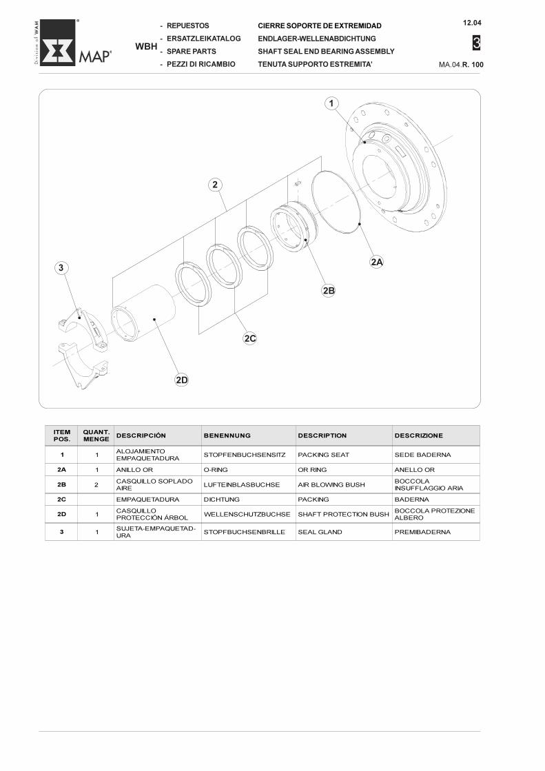
12.04
MA.04.R. 100
3
-
-
-
-
WBH
REPUESTOS
ERSATZLEIKATALOG
SPARE PARTS
PEZZI DI RICAMBIO
CIERRE SOPORTE DE EXTREMIDAD
ENDLAGER-WELLENABDICHTUNG
SHAFT SEAL END BEARING ASSEMBLY
TENUTA SUPPORTO ESTREMITA’
ITEMPOS.
QUANT.MENGE
DESCRIPCIÓN BENENNUNG DESCRIPTION DESCRIZIONE
1 1ALOJAMIENTOEMPAQUETADURA
STOPFENBUCHSENSITZ PACKING SEAT SEDE BADERNA
2A 1 ANILLO OR O-RING OR RING ANELLO OR
2B 2CASQUILLO SOPLADOAIRE
LUFTEINBLASBUCHSE AIR BLOWING BUSHBOCCOLAINSUFFLAGGIO ARIA
2C EMPAQUETADURA DICHTUNG PACKING BADERNA
2D 1CASQUILLOPROTECCIÓN ÁRBOL
WELLENSCHUTZBUCHSE SHAFT PROTECTION BUSHBOCCOLA PROTEZIONEALBERO
3 1SUJETA-EMPAQUETAD-URA
STOPFBUCHSENBRILLE SEAL GLAND PREMIBADERNA
•
3
2
•
1
•
2D
2C
•
2B
•
2A
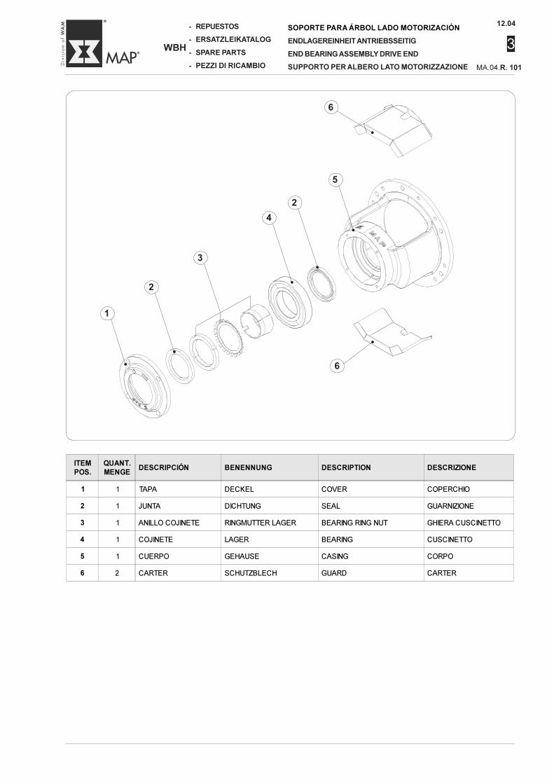
12.04
3
-
-
-
-
WBH
REPUESTOS
ERSATZLEIKATALOG
SPARE PARTS
PEZZI DI RICAMBIO MA.04.R. 101
SOPORTE PARA ÁRBOL LADO MOTORIZACIÓN
ENDLAGEREINHEIT ANTRIEBSSEITIG
END BEARING ASSEMBLY DRIVE END
SUPPORTO PER ALBERO LATO MOTORIZZAZIONE
•
1
•
2
3
•
4
•
2
•
5
•
6
•
6
ITEMPOS.
QUANT.MENGE
DESCRIPCIÓN BENENNUNG DESCRIPTION DESCRIZIONE
1 1 TAPA DECKEL COVER COPERCHIO
2 1 JUNTA DICHTUNG SEAL GUARNIZIONE
3 1 ANILLO COJINETE RINGMUTTER LAGER BEARING RING NUT GHIERA CUSCINETTO
4 1 COJINETE LAGER BEARING CUSCINETTO
5 1 CUERPO GEHAUSE CASING CORPO
6 2 CARTER SCHUTZBLECH GUARD CARTER
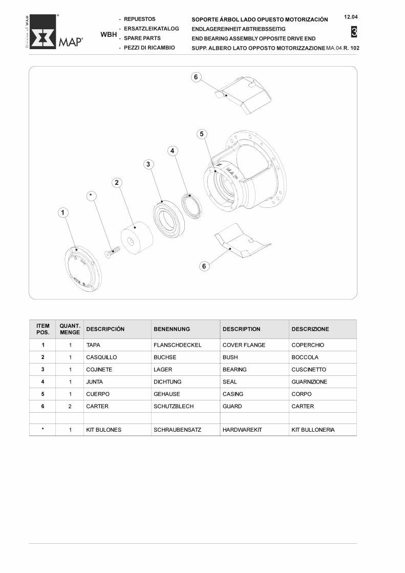
12.04
MA.04.R. 102
3
-
-
-
-
WBH
REPUESTOS
ERSATZLEIKATALOG
SPARE PARTS
PEZZI DI RICAMBIO
SOPORTE ÁRBOL LADO OPUESTO MOTORIZACIÓN
ENDLAGEREINHEIT ABTRIEBSSEITIG
END BEARING ASSEMBLY OPPOSITE DRIVE END
SUPP. ALBERO LATO OPPOSTO MOTORIZZAZIONE
ITEMPOS.
QUANT.MENGE
DESCRIPCIÓN BENENNUNG DESCRIPTION DESCRIZIONE
1 1 TAPA FLANSCHDECKEL COVER FLANGE COPERCHIO
2 1 CASQUILLO BUCHSE BUSH BOCCOLA
3 1 COJINETE LAGER BEARING CUSCINETTO
4 1 JUNTA DICHTUNG SEAL GUARNIZIONE
5 1 CUERPO GEHAUSE CASING CORPO
6 2 CARTER SCHUTZBLECH GUARD CARTER
* 1 KIT BULONES SCHRAUBENSATZ HARDWAREKIT KIT BULLONERIA
•
1
•
*
•
2
•
3
•
4
•
5
•
6
•
6


fax
internet
videoconferenze
+ 39 / 0535 / 618111
+ 39 / 0535 / 618226
www.wamgroup.com
+ 39 / 0535 / 49032
N.B. Los datos presentes en este catálogo no son vinculantes y pueden sufrir variaciones en cualquier momento.N.B. Angaben ohne Gewähr. Änderungen können ohne Vorankündigung vorgenommen werden.N.B. Rights reserved to modify technical specificationsN.B. Tutti i dati riportati nel presente catalogo non sono impegnativi e possono subire variazioni in qualsiasi momento.
WAM S.p.A. - MAP Division
Via Cavour, 338I - 41030 Ponte MottaCavezzo (MO) - ITALY