Embed Size (px)
Citation preview
Hochschule DarmstadtFachbereich Media
Studiengang Information Science & Engineering/ Informationswissenschaft
Masterarbeit
Thema: User Interface Development based on XML Schema
Bearbeiter: Maximilian RichterImmatrikulationsnummer: 724764
Referent: Prof. Dr. Bernhard Thull
Korreferent: Prof. Dr. rer. nat. Reginald Ferber
Abgabe: 2. Juli 2012
Abstract
This master thesis describes the potentials of developing a user interface based onan existing XML Schema definition. The focus is on automatic methods for creatinginterface elements.
The theoretical and practical basics and referenced fields are described and theircontribution to the solution approaches are explained. Two such prototypical im-plementations are demonstrated and compared: a) the Eclipse Modeling Framework(EMF) in combination with the Extended Editing Framework (EEF) as an Eclipse-based and thus Java-based software generation framework, and b) a browser-basedprototype that builds on HTML5, CSS and JavaScript/CoffeeScript. It follows theModel-View-Controller paradigm, its generation concept is developed by the authorand concretely implemented with the scripting language Python.
Zusammenfassung
In dieser Masterarbeit werden die Moglichkeiten beschrieben, wie auf Basis der ex-istierenden XML-Schema-Definition fur die Projektinformationssprache PrIML ein ge-eignetes User Interface erstellt werden kann. Der Fokus liegt dabei auf den Potentialender automatischen Erzeugung von Oberflachen-Elementen.
Es werden die theoretischen und praktischen Grundlagen und Bezuge dargestelltund deren Beitrag zur Losung der Aufgabenstellung deutlich gemacht. Zwei Ansatzefur konkrete prototypische Umsetzungen werden in der Arbeit vorgestellt und ver-glichen: a) das Eclipse Modeling Framework (EMF) in Kombination mit dem ExtendedEditing Framework (EEF) als Eclipse- und damit Java-basierter Ansatz der Software-Generierung und b) eine Browser-basierte Losung, die HTML5, CSS und JavaScript/CoffeeScript einsetzt, auf dem Model-View-Controller-Paradigma basiert und dessenGeneratorschritte selbst konzeptioniert und mit der Skriptsprache Python umgesetztsind.
ii
Declaration
I hereby declare that I wrote this thesis autonomously and no other than the listedreferences have been used.Precise, explicit and complete citations are applied whenever I referred to external ma-terials, texts or notions.All other content in this thesis was created by myself if not stated otherwise.I accept that it is an attempt of deception if this declaration proves to be incorrect.
Date Signature
Erklarung
Hiermit erklare ich, dass ich die vorliegende Arbeit selbstandig erstellt und keine an-deren als die angegebenen Hilfsmittel und Quellen benutzt habe.Soweit ich auf fremde Materialien, Texte oder Gedankengange zuruckgegriffen habe,enthalten meine Ausfuhrungen vollstandige und eindeutige Verweise auf die Urheberund Quellen.Alle weiteren Inhalte der vorgelegten Arbeit stammen im urheberrechtlichen Sinn vonmir, soweit keine Verweise und Zitate erfolgen.Mir ist bekannt, dass ein Tauschungsversuch vorliegt, wenn die vorstehende Erklarungsich als unrichtig erweist.
Ort, Datum Unterschrift
iii

Declaration Concerning Library Services
Please choose:
O I agree that this thesis is loaned to library users.
O I do not agree that this thesis is loaned to library users. It contains confiden-tial corporate information and is thus not accessible to the public.
Date Signature
Erklarung zur Ausleihe
Bitte ankreuzen:
O Mit der Ausleihe der gedruckten Abschlussarbeit bin ich einverstanden.
O Mit der Ausleihe der gedruckten Abschlussarbeit bin ich nicht einverstanden. DieArbeit ist gesperrt, da sie in einem Betrieb durchgefuhrt wurde und ihr Inhalt ausdruck-lich durch diesen gesperrt ist. (Vgl. ABPO § 18 (9))
Ort, Datum Unterschrift
iv
List of Figures
2.1 Requirement extract from a work report trace HTML file . . . . . . . . 5
3.1 UsiXML model components . . . . . . . . . . . . . . . . . . . . . . . . . 13
5.1 XML Schema components . . . . . . . . . . . . . . . . . . . . . . . . . . 215.2 OMG EMOF class diagram . . . . . . . . . . . . . . . . . . . . . . . . . 245.3 Ecore meta-model hierarchy . . . . . . . . . . . . . . . . . . . . . . . . . 26
6.1 Workflow generation of the browser-based application . . . . . . . . . . 306.2 Web application screen shot . . . . . . . . . . . . . . . . . . . . . . . . . 336.3 Generation steps EMF . . . . . . . . . . . . . . . . . . . . . . . . . . . . 456.4 Generated PrIML EMF Editor . . . . . . . . . . . . . . . . . . . . . . . 466.5 Generated PrIML EEF Editor . . . . . . . . . . . . . . . . . . . . . . . . 476.6 Generation steps EEF . . . . . . . . . . . . . . . . . . . . . . . . . . . . 486.7 EEF widget AdvancedTableComposition . . . . . . . . . . . . . . . . . . 516.8 EEF widget TableComposition . . . . . . . . . . . . . . . . . . . . . . . 51
A.1 Flow chart: method simpleType2Python(...) . . . . . . . . . . . . . . 76A.2 Flow chart: method complexType2Python(...) . . . . . . . . . . . . . 77A.3 Flow chart: method getFlatElementsMapForComplexType(...) . . . . 79A.4 Flow chart: method getModelForComplexType(...) . . . . . . . . . . . 80A.5 Flow chart: method getTemplateForComplexType(...) . . . . . . . . . 82A.6 Flow chart: method getControllerForComplexType(...) . . . . . . . 83A.7 Flow chart: method getJsonixMappingForComplexType(...) . . . . . 85
v
List of Listings
2.1 Requirement XML extract . . . . . . . . . . . . . . . . . . . . . . . . . . 5
5.1 Requirement XML Schema fragment . . . . . . . . . . . . . . . . . . . . 22
6.1 Complex type for requirement groups flattened (serialized in JSON; ex-tract) . . . . . . . . . . . . . . . . . . . . . . . . . . . . . . . . . . . . . 38
6.2 Backbone.RelationalModel definition for requirement groups . . . . . . . 396.3 jQuery template for requirement group . . . . . . . . . . . . . . . . . . . 406.4 Spine.Controller for requirement groups in CoffeeScript . . . . . . . . . 416.5 Jsonix mapping for requirement groups (extract) . . . . . . . . . . . . . 436.6 Layout configuration for EEF references table . . . . . . . . . . . . . . . 526.7 Manually added source code for history expansion on requirement addition 55
List of Tables
6.1 Mapping between XML Schema types and HTML constructs . . . . . . 366.2 Comparison of requirements . . . . . . . . . . . . . . . . . . . . . . . . . 58
vi
Abbreviations
ABPO Allgemeine Bestimmungen fur Prufungsordnungen
AJAX Asynchronous JavaScript And XML
API Application Programming Interface
AUI Abstract User Interface
CD-ROM Compact Disc-Read Only Memory
cf. confer
CRUD Create, Retrieve, Update, Delete; Common tasks in data manipulation
CSS Cascading Style Sheets
CTD Complex Type Definition
CUI Concrete User Interface
CWM Common Warehouse Metamodel
DOCX XML-based document format by Microsoft Word
DOM Document Object Model
DRY “Don’t Repeat Yourself”
DSDL Document Schema Definition Languages
DSL Domain-specific language
DTD Document Type Definition
ECMA European Computer Manufacturers Association
EEF Extended Editing Framework
e.g. exempli gratia (engl.: for example)
EMF Eclipse Modeling Framework
EMFT Eclipse Modeling Framework Technology
EMOF Essential Meta Object Facility
EPF Eclipse Process Framework
vii
f./ff. folio (engl.: on the next [page(s)])
FUI Final User Interface
GUI Graphical User Interface
HCI Human Computer Interaction
HTML Hyper Text Markup Language
ID Identifier
IDE Integrated Development Environment
ISCUE Nuremburgian software firm; developers of PrIML
i.e. id est (engl.: that is)
JAXB Java XML Bidnings
JRE Java Runtime Environment
JSON JavaScript Object Notation
LESS [In fact not an abbreviation]
MacOS Macintosh Operation System
MBSD Model-based software development
MBUI Model-based User Interface
MBUID Model-based User Interface Development
MOF Meta Object Facility
MVC Model-View-Controller
OMG Object Management Group
OOP Object-Oriented Programming
p./pp. page/pages
PDA Personal Digital Assistant
PDF Portable Document Format
PHP PHP Homepage Pre-Processor
PIM Platform-independent model
PrIML Project Information Markup Language
PrIOF Project Intermediate Output Format
viii
PSM Platform-specific model
PyXB Python XML Bindings
Qt GUI Toolkit with bindings for many programming languages
RDBMS Relational Data Base Management System
RDF Resource Description Framework
SASS Syntactically Awesome Stylesheets
SGML Standard Generalized Markup Language
STD Simple Type Definition
UI User Interface
UIDL User Interface Description Language
UIMS User Interface Management System
UML Unified Modeling Language
UsiXML USer Interface eXtensible Markup Language
VM Virtual Machine
W3C World Wide Web Consortium
XInclude XML Include; standard for weaving together the content of XML files
XMI XML Metadata Interchange
XML eXtensible Markup Language
XPath XML Path; language for addressing nodes in XML structures
XQuery XML Query; language for programmatically querying XML collections
XSD XML Schema Definition
XSLT XML Stylesheet Language Transformation
ix
Contents
1 Introduction 11.1 Goals . . . . . . . . . . . . . . . . . . . . . . . . . . . . . . . . . . . . . 11.2 Thesis Structure . . . . . . . . . . . . . . . . . . . . . . . . . . . . . . . 1
2 Project Information Markup Language (PrIML) 42.1 Goals . . . . . . . . . . . . . . . . . . . . . . . . . . . . . . . . . . . . . 42.2 Model . . . . . . . . . . . . . . . . . . . . . . . . . . . . . . . . . . . . . 42.3 Design Decisions . . . . . . . . . . . . . . . . . . . . . . . . . . . . . . . 62.4 Workflow . . . . . . . . . . . . . . . . . . . . . . . . . . . . . . . . . . . 7
2.4.1 XML Authoring . . . . . . . . . . . . . . . . . . . . . . . . . . . 72.4.2 Transformation Processes . . . . . . . . . . . . . . . . . . . . . . 7
2.5 Relation to Thesis Scope . . . . . . . . . . . . . . . . . . . . . . . . . . . 8
3 User Interface Development 93.1 Overview . . . . . . . . . . . . . . . . . . . . . . . . . . . . . . . . . . . 93.2 Model-Based User Interface Development . . . . . . . . . . . . . . . . . 10
3.2.1 Goals . . . . . . . . . . . . . . . . . . . . . . . . . . . . . . . . . 103.2.2 Definitions . . . . . . . . . . . . . . . . . . . . . . . . . . . . . . 113.2.3 Standards and Paradigms . . . . . . . . . . . . . . . . . . . . . . 123.2.4 Limitations . . . . . . . . . . . . . . . . . . . . . . . . . . . . . . 14
3.3 Relation to Thesis Scope . . . . . . . . . . . . . . . . . . . . . . . . . . . 14
4 Model-Based Software Development 154.1 Goals . . . . . . . . . . . . . . . . . . . . . . . . . . . . . . . . . . . . . 15
4.1.1 Efficiency . . . . . . . . . . . . . . . . . . . . . . . . . . . . . . . 154.1.2 Consistency . . . . . . . . . . . . . . . . . . . . . . . . . . . . . . 164.1.3 DRY (Don’t Repeat Yourself) . . . . . . . . . . . . . . . . . . . . 16
4.2 Methods . . . . . . . . . . . . . . . . . . . . . . . . . . . . . . . . . . . . 164.3 Relation to Thesis Scope . . . . . . . . . . . . . . . . . . . . . . . . . . . 18
5 Modelling 195.1 Languages and Standards . . . . . . . . . . . . . . . . . . . . . . . . . . 19
5.1.1 Unified Modeling Language . . . . . . . . . . . . . . . . . . . . . 195.1.2 XML-Related Standards . . . . . . . . . . . . . . . . . . . . . . . 19
5.2 Meta-Modelling . . . . . . . . . . . . . . . . . . . . . . . . . . . . . . . . 235.2.1 Meta Object Facility . . . . . . . . . . . . . . . . . . . . . . . . . 255.2.2 Eclipse Modeling Framework and Ecore . . . . . . . . . . . . . . 255.2.3 Similarities . . . . . . . . . . . . . . . . . . . . . . . . . . . . . . 25
5.3 Relation to Thesis Scope . . . . . . . . . . . . . . . . . . . . . . . . . . . 26
x
6 Practical Solution Approaches 276.1 Requirements for User Interface Solution . . . . . . . . . . . . . . . . . . 286.2 Browser-Based Application . . . . . . . . . . . . . . . . . . . . . . . . . 29
6.2.1 Generating Models . . . . . . . . . . . . . . . . . . . . . . . . . . 326.2.2 Generating Views . . . . . . . . . . . . . . . . . . . . . . . . . . . 346.2.3 Generating Controllers . . . . . . . . . . . . . . . . . . . . . . . . 376.2.4 Generating JavaScript-XML bindings . . . . . . . . . . . . . . . 37
6.3 Plugin Using Eclipse Modeling Framework . . . . . . . . . . . . . . . . . 446.3.1 Overview . . . . . . . . . . . . . . . . . . . . . . . . . . . . . . . 446.3.2 Generation Processes and Development Steps . . . . . . . . . . . 466.3.3 Customization Steps . . . . . . . . . . . . . . . . . . . . . . . . . 49
6.4 Comparison . . . . . . . . . . . . . . . . . . . . . . . . . . . . . . . . . . 566.4.1 Requirement-Based Evaluations . . . . . . . . . . . . . . . . . . . 566.4.2 Overall Comparison . . . . . . . . . . . . . . . . . . . . . . . . . 616.4.3 Recommendations for ISCUE . . . . . . . . . . . . . . . . . . . . 62
7 Conclusions and Lessons Learned 64
Bibliography 67
A Detailed Generation Step Descriptions 74A.1 Web Application . . . . . . . . . . . . . . . . . . . . . . . . . . . . . . . 74
A.1.1 Environment Setup . . . . . . . . . . . . . . . . . . . . . . . . . . 74A.1.2 Preparation Methods . . . . . . . . . . . . . . . . . . . . . . . . . 75A.1.3 Templating Methods for MVC Components . . . . . . . . . . . . 78A.1.4 Additional Generation Methods . . . . . . . . . . . . . . . . . . . 84
A.2 Eclipse-Based . . . . . . . . . . . . . . . . . . . . . . . . . . . . . . . . . 86A.2.1 Environment Setup . . . . . . . . . . . . . . . . . . . . . . . . . . 86A.2.2 Eclipse Modeling Framework (EMF) . . . . . . . . . . . . . . . . 86A.2.3 Extended Editing Framework (EEF) . . . . . . . . . . . . . . . . 88
B Thesis CD-ROM Contents 90
xi

1 Introduction
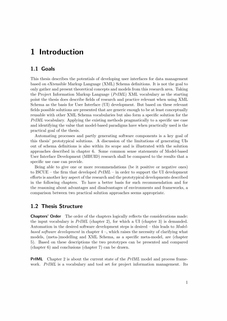
1.1 Goals
This thesis describes the potentials of developing user interfaces for data managementbased on eXtensible Markup Language (XML) Schema definitions. It is not the goal toonly gather and present theoretical concepts and models from this research area. Takingthe Project Information Markup Language (PrIML) XML vocabulary as the startingpoint the thesis does describe fields of research and practice relevant when using XMLSchema as the basis for User Interface (UI) development. But based on these relevantfields possible solutions are presented that are generic enough to be at least conceptuallyreusable with other XML Schema vocabularies but also form a specific solution for thePrIML vocabulary. Applying the existing methods pragmatically to a specific use caseand identifying the value that model-based paradigms have when practically used is thepractical goal of the thesis.
Automating processes and partly generating software components is a key goal ofthis thesis’ prototypical solutions. A discussion of the limitations of generating UIsout of schema definitions is also within its scope and is illustrated with the solutionapproaches described in chapter 6. Some common sense statements of Model-basedUser Interface Development (MBUID) research shall be compared to the results that aspecific use case can provide.
Being able to give one or more recommendations (be it positive or negative ones)to ISCUE – the firm that developed PrIML – in order to support the UI developmentefforts is another key aspect of the research and the prototypical developments describedin the following chapters. To have a better basis for such recommendation and forthe reasoning about advantages and disadvantages of environments and frameworks, acomparison between two practical solution approaches seems appropriate.
1.2 Thesis Structure
Chapters’ Order The order of the chapters logically reflects the considerations made:the input vocabulary is PrIML (chapter 2), for which a UI (chapter 3) is demanded.Automation in the desired software development steps is desired – this leads to Model-based software development in chapter 4 –, which raises the necessity of clarifying whatmodels, (meta-)modelling and XML Schema, as a specific meta-model, are (chapter5). Based on these descriptions the two prototypes can be presented and compared(chapter 6) and conclusions (chapter 7) can be drawn.
PrIML Chapter 2 is about the current state of the PrIML model and process frame-work. PrIML is a vocabulary and tool set for project information management. Its
1
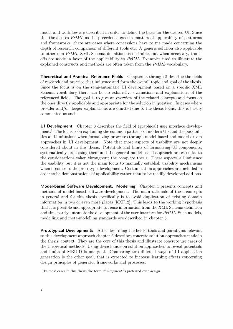
model and workflow are described in order to define the basis for the desired UI. Sincethis thesis uses PrIML as the precedence case in matters of applicabilty of platformsand frameworks, there are cases where concessions have to me made concerning thedepth of research, comparison of different tools etc. A generic solution also applicableto other non-PrIML XML Schema definitions is desirable, but when necessary, trade-offs are made in favor of the applicability to PrIML. Examples used to illustrate theexplained constructs and methods are often taken from the PrIML vocabulary.
Theoretical and Practical Reference Fields Chapters 3 through 5 describe the fieldsof research and practice that influence and form the overall topic and goal of the thesis.Since the focus is on the semi-automatic UI development based on a specific XMLSchema vocabulary there can be no exhaustive evaluations and explanations of thereferenced fields. The goal is to give an overview of the related concepts and focus onthe ones directly applicable and appropriate for the solution in question. In cases wherebroader and/or deeper explanations are omitted due to the thesis focus, this is brieflycommented as such.
UI Development Chapter 3 describes the field of (graphical) user interface develop-ment.1 The focus is on explaining the common patterns of modern UIs and the possibili-ties and limitations when formalizing processes through model-based and model-drivenapproaches in UI development. Note that most aspects of usability are not deeplyconsidered about in this thesis. Potentials and limits of formalizing UI components,systematically processing them and the general model-based approach are essential tothe considerations taken throughout the complete thesis. These aspects all influencethe usability but it is not the main focus to manually establish usability mechanismswhen it comes to the prototype development. Customization approaches are included inorder to be demonstrations of applicability rather than to be readily developed add-ons.
Model-based Software Development. Modelling Chapter 4 presents concepts andmethods of model-based software development. The main rationale of these conceptsin general and for this thesis specifically is to avoid duplication of existing domaininformation in two or even more places [KXF12]. This leads to the working hypothesisthat it is possible and appropriate to reuse information from the XML Schema definitionand thus partly automate the development of the user interface for PrIML. Such models,modelling and meta-modelling standards are described in chapter 5.
Prototypical Developments After describing the fields, tools and paradigms relevantto this development approach chapter 6 describes concrete solution approaches made inthe thesis’ context. They are the core of this thesis and illustrate concrete use cases ofthe theoretical methods. Using these hands-on solution approaches to reveal potentialsand limits of MBUID is one goal. Comparing two different ways of UI applicationgeneration is the other goal, that is expected to increase learning effects concerningdesign principles of generator frameworks and processes.
1In most cases in this thesis the term development is preferred over design.
2

Conclusions and Lessons Learned Chapter 7 evaluates the results of the thesis andcompares them with the initial goals. Recommendations in terms of framework appro-priateness and possible limits of approaches are the pragmatic aspect of the conclusionsthat shall be drawn in this chapter. Technical and methodical lessons learned will alsobe part of this final chapter.
3
2 Project Information Markup Language(PrIML)2
2.1 Goals
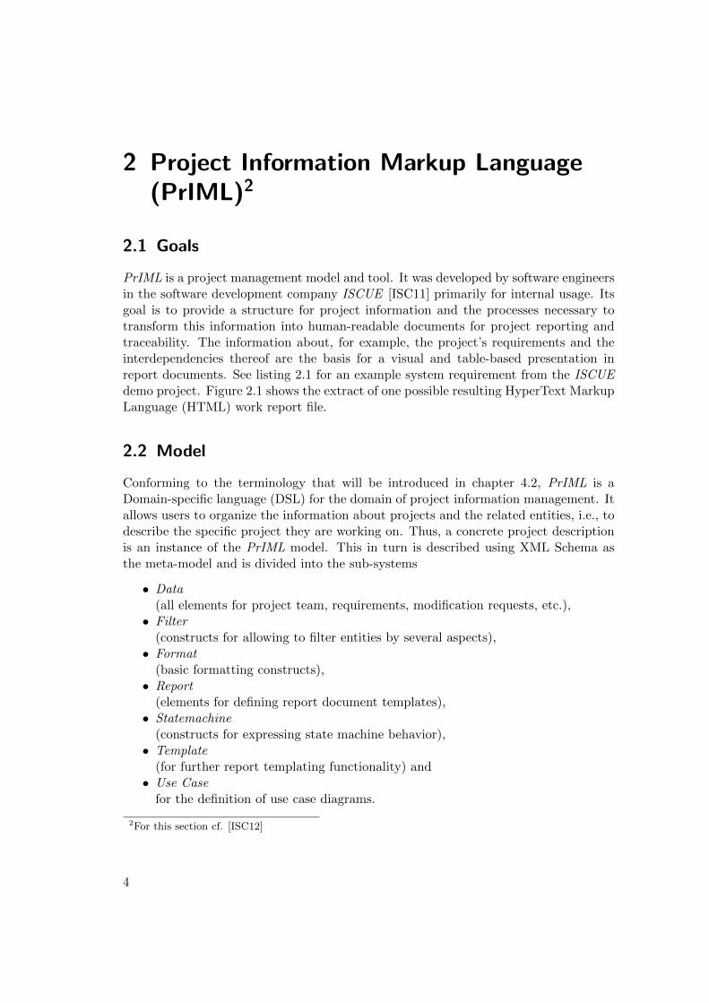
PrIML is a project management model and tool. It was developed by software engineersin the software development company ISCUE [ISC11] primarily for internal usage. Itsgoal is to provide a structure for project information and the processes necessary totransform this information into human-readable documents for project reporting andtraceability. The information about, for example, the project’s requirements and theinterdependencies thereof are the basis for a visual and table-based presentation inreport documents. See listing 2.1 for an example system requirement from the ISCUEdemo project. Figure 2.1 shows the extract of one possible resulting HyperText MarkupLanguage (HTML) work report file.
2.2 Model
Conforming to the terminology that will be introduced in chapter 4.2, PrIML is aDomain-specific language (DSL) for the domain of project information management. Itallows users to organize the information about projects and the related entities, i.e., todescribe the specific project they are working on. Thus, a concrete project descriptionis an instance of the PrIML model. This in turn is described using XML Schema asthe meta-model and is divided into the sub-systems
• Data(all elements for project team, requirements, modification requests, etc.),• Filter
(constructs for allowing to filter entities by several aspects),• Format
(basic formatting constructs),• Report
(elements for defining report document templates),• Statemachine
(constructs for expressing state machine behavior),• Template
(for further report templating functionality) and• Use Case
for the definition of use case diagrams.
2For this section cf. [ISC12]
4
1 <requirement id="SysReq_0003">
2 <history version="1" editor="oseidel"
3 date="2008 -10 -23" change="created" />
4 <description >
5 The stopwatch should run independent of the
operating system.
6 </description >
7 <val_criteria >
8 The stopwatch runs in a browser.
9 </val_criteria >
10 <references >
11 <refine >
12 <external_document refId="extDocCustReq">
13 <version version="1" state="done" />
14 </external_document >
15 <requirement refId="SysReq_0002">
16 <version state="done" version="1" />
17 </requirement >
18 </refine >
19 </references >
20 </requirement >
Listing 2.1: Requirement XML extract
Figure 2.1: Requirement extract from a work report trace HTML file
5
In addition to these there is the declaration of an intermediate XML format calledProject Intermediate Output Format (PrIOF ) that is used in the transformation pro-cesses described below. See the thesis CD-ROM for detailed visualization images of thePrIML sub-system XML Schema Definitions (XSDs).
2.3 Design Decisions
Creating PrIML was in the first step a conceptual process. There existed ideas andconcepts of entity types, their possible relations and the general request for modelextensibility when needed.
An essential design decision was not to use a Relational Data Base ManagementSystem (RDBMS). Efficient versioning and diff3 mechanisms, back-up functionalityand collaboration were key goals of PrIML and RDBMSs could not meet these goalssufficiently.
One approach considered in the early development phase was making PrIML a Doxy-gen [Dox12] add-on and extending the commment structure that this tool provides. Thelack of a reliable syntax basis and the intermixing of project information with sourcecode discouraged this approach.
In the next steps the following main design decisions were made:
• use the XML standards family as highly standardized and well-supported in termsof tools and adaption in practice,• use XML as the desired serialization format for project description instances,• use XML Schema as the meta-modelling language for convenient element, type,
attribute and group declaration constructs and• use XML Stylesheet Language Transformation (XSLT) as the language for de-
scribing the transformation (and information enhancement) processes.
Originally PrIML-conforming project descriptions had to be stored in one XML fileand were processed by one XSLT script directly in the web browser. Thus HTML wasin that state the only output format directy available and due to browser renderingXSLT 1.0 was the transformation standard used.4 With the need for more complextransformations that demanded for temporary result tree construction introduced byXSLT 2.0 and the request for more output formats, a re-design proved to be necessary.
The necessity for an intermediate data format between PrIML instance documentsand the generated report document files arose and characterized the re-design. Thanksto this intermediate format, introducing new features in the PrIML model definitiononly affects one transformation step, i.e., the one that transforms PrIML instancesinto PrIOF. The further transformations are not affected by schema changes, they are“facaded” by the intermediate format. Additional output formats can easily be addedto this intermediate format as well.
The XML Schema definitions are separated according to the subsystems mentionedabove and stored in respective .xsd files. This modularization reflects the complemen-
3The name of the Unix tool diff [Chr93] is often used to generally describe the step of tracking datachanges.
4Web browsers do not fully (or not at all) support XSLT 2.0 transformations.
6
tarity of the different vocabulary aspects, the parts are interwoven via xsd:import
directives as needed. Modularity and the ability for recombination and independentediting by potentially more than one developer is also desired on the instance level.Therefore the element definitions in the XML Schema files are constructed as to enablethe user to choose many different PrIML elements as potential document root elements.This allows for nearly arbitrarily granular modularization. Bringing together these sep-arated instance document fragments is realized via XInclude statements. Including viathe XInclude standard also demands that an xml:base attribute is allowed to occuron the level of the to-be-included element.
2.4 Workflow
The current PrIML workflow grounds on the XML Schema model files and XSLT pro-cesses. It uses an XML processor for performing the tasks of validation and trans-formation. Eclipse is used as the platform bundling all components. It includes thebasic XML perspective,5 the XML processor Saxon B [Kay09] and Ant [Apa12] buildsupport.
2.4.1 XML Authoring
XML authoring, i.e., the data entry of XML structures, is accomplished through theXML perspective of Eclipse. It provides users with basically two different views. Thedesign view uses a tree structure for presenting and editing the XML. The source viewlets users directly edit the XML source code. Both views provide guidance mechanismssuch as context-sensitive suggestions for sub-element and attribute creation or the pre-sentation of documentation text fragments retrieved from the referenced XML Schemafile.
The model requires IDs for entities of some types. These IDs have to be uniquethroughout the complete project description and have to match a defined pattern. IDshave to be manually specified and maintained correctly when it comes to referencingthem from other entities. XML Schema’s xsd:unique construct is used. The validationprocess uses it to raise errors in case the uniqueness of IDs is not obeyed.
2.4.2 Transformation Processes
Based on the aforementioned project descriptions in XML files there are XSLT [W3C07]processes transforming the data via PrIOF into structurally pre-defined report doc-uments. The processes are bundled into Ant build files and can be executed fromwithin the Eclipse Integrated Development Environment (IDE). Directory clean-upsand eventual sub-directory creations accompany the core XML validation and XSLTtransformation steps.
An important step before any of the output is generated is the building of a tem-porary result tree. It contains information about relationships between entities in theprocessed instance document(s). This information has to be resolved in a complex
5Eclipse uses the term perspective for pre-configured user interface subsets that fit the respectivecontext, in this case XML authoring and editing.
7
manner because it is not directly accessible in all possible directions out of the XMLinstance document(s). Internally this tree is called BiDirTraceTree, indicating the bi-directionality. This means that even if a reference between two entities is only assertedfrom one of the involved entities, it is made accessible from both directions via theBiDirTraceTree.
Possible result formats of the transformation processes are currently HTML, DOCXand the Portable Document Format (PDF). These are viewed by users with the re-spective viewer tools such as a web browser, office suite and PDF viewer. The PrIMLsubsystem for reports provides the language constructs for defining report “skeletons”for respective report documents. Filter mechanisms are defined in PrIML’s filter XSDfile for selecting specific instances matching (potentially arbitrarily deep nested) fil-ter rules. The report documents are populated with the concrete data by the XSLTprocesses.
2.5 Relation to Thesis Scope
The basic design decisions as well as the current state of PrIML’s model and workflowhave been described. They define the tool’s state and the basis for this thesis’ consid-erations for UI solutions. Building upon the premises, existing model definitions andprocesses, the PrIML framework uses, the relevant fields of research and practice canbe described.
The focus of these following chapters mainly follows the applicability for the PrIMLuse case.
8
3 User Interface Development
3.1 Overview
The field of UI devlopment belongs to the more general research field of Human Com-puter Interaction (HCI). The latter subsumes all aspects of human users interactingwith computers and vice versa. Generally put, UIs are the “[...] directly experiencedaspects of a thing or device” ([Tra09], p. 9) and for most users “[...] the distinctionbetween interface and system is [...] meaningless” ([Tra09], p. 1). De facto there is adifference between the UI as the front end of an application and the back-end processescarrying out more complex computations and doing data persistence.
Over the last few years there have been developments towards common features of UIs(cf. [Mye00], p. 2). The tendency to provide users with a graphical user interface (GUI)instead of a textual (command line) interface is such a common feature on a particularlylow level. The fact that keyboard and mouse are widely accepted as the translatingunits between physical interaction and computable signals is another basic commonality.Building on this graphical fundament and the peripheral units for interaction there havebeen developed different sorts of features and interaction patterns, mostly referred toas widgets. These are the components that GUIs are constructed of. Frequently usedexamples are group boxes, buttons, drop-down lists, navigation menus and text inputfields.
Research in UI development distinguishes between different interaction patterns suchas direct manipulation, menu selection, form fill-in, command language and naturallanguage (cf. [Shn10], pp. 84ff.). They differ in terms of the level of formalization andspecificity respectively. Enabling users to directly manipulate items in a UI usuallyallows a more natural way of interacting and editing. Generally, using appropriatemetaphors (cf. [App11]) in UIs is crucial since it reflects the tasks to be performed inan intuitive manner. An example used throughout operating systems such as Windowsand MacOS is the metaphor of a desktop as the basic interaction space for the user[Wik12a]. This is often complemented by adapting the task of putting an object intothe trash can to the task of deleting a file, object or folder (cf. [Shn10], p. 192). It is anexample of bringing concepts into a UI that are not 1:1 (in a physical way) applicablebut intuitively acceptable by users.
Within certain contexts such as operating systems, windowing systems or corpora-tions there often exist guide lines for UI design patterns. An example is [App11] forthe MacOS operating system, similar standards exist for Android-based applications[Goo12] and other contexts. Creating elements of recognition and thus lowering theacceptance and understanding threshold are the main goals of such guide lines. The“look and feel” of a system is in most cases desired to be perceived consistently. AUI that behaves and/or looks different from the user’s expectation can easily lead toconfusion or even rejection (cf. [Shn10], pp. 23 and 88).
9
3.2 Model-Based User Interface Development
For several years there have been surveys concerning the costs and efforts in softwaredevelopment. Especially the role of UI development as a sub-category of softwaredevelopment is a prominent one. UIs are the front end of a software system and theyreflect the functionality and the way of interacting with it. A great amount of timeand effort of software projects is put into UI development (cf. [Mye92], p. 1956) andfor many years the necessity to make UI development more efficient has been focused.The goals and important concepts of these approaches are described below. In general,model-based UI development aims at formally describing user interfaces and introducingabstraction layers between the domain, the user’s tasks and the UI itself – mostly withabstract, concrete and final aspects ([Sch96], pp. 7ff.; cf. [Cal03], p. [5]).
Just recently the World Wide Web Consortium (W3C) founded the Model-Based UserInterfaces (MBUI) Working Group that in its mission statement formulates the plan to”[...] develop standards as a basis for interoperability across authoring tools for contextaware user interfaces for Web-based interactive applications.” [W3C11a] The workinggroup’s “initial focus is on task models, and UI components and integrity constraintsat a level of abstraction independent of the choice of device” [W3C11a] and will laterinclude the more concrete UI levels (cf. [W3C11a]).
3.2.1 Goals
The main MBUID goals reusability, flexibility and platform-independence (cf. [Leh05],p. 9) and multi-modality are described in this chapter.
Reusability Reusing components and re-occurring patterns is crucial in MBUID. Thecommon aspects of UIs can be abstracted out and do not have to be newly implementedin every UI. The fact that data structures are mapped to UI widgets in often similarways can influence MBUID systems. Such mappings leverage reusability.
Flexibility When applying MBUID patterns it is possible to remain flexible in termsof widget representations and layout decisions (cf. [Pin03], p. 62). Design decisions areout-sourced and declared centrally. Changing it causes direct reflection in all applicablecontexts. Refactoring of the UI can be realized without expensive re-development, thisincreases flexibility.
Multi-Platform/-Device Although the importance of software development for dif-ferent types of devices such as Personal Digital Assistant (PDAs) and cell phones hasbeen stressed for several years, it has only reached broad attention and adoption throughmain-stream product families such as smart phones and tablet computers in the lastfew years.
Apart from device-specific implementation differences there has always been themulti-platform issue, i.e., the development for different operating systems. In a broadersense the term multi-platform development can also include implementations based on
6Although this survey dates back to 1992 it has been frequently cited since then, cf. [Mei11b], p. 2
10
different IDE frameworks and/or different web browsers when it comes to web-basedapplications.
The development for different platforms and/or devices can be simplified with MBUIDmethods. Using a UI model for platform-specific UI generation processes can avoidduplicating implementation efforts. General platform-independent models (PIMs) aretransformed into platform-specific models (PSMs) by adding specific aspects of therespective target platform.
Multi-Modality Declaring UI elements in different levels of abstraction in modelsmakes the development of multi-modal interfaces easier. One UI model (or more thanone with each one representing a different aspect of it) can be the basis for differentmanifestations. Gesture-based and voice-operated are important examples of interac-tion techniques that can be propelled by model-based development methods. Multi-modality often co-occurs with device specifica; smart phones and tablets for examplehave accelerometers that form the basis for motion interaction. Desktop computers donot provide such interaction methods, the same application may however be availablethere as well. One task that a user can accomplish with the application has to bemanifested in different ways, dependent on the modalities the respective device offers.
3.2.2 Definitions
There are concepts and model distinctions in MBUID that are frequently used andimplemented. These are defined in this chapter. It is worth noting that not everypossible model type is demanded and/or applicable in every framework and MBUIDcontext (cf. [Sze96], p. xxiv; cf. [Sch96], p. 7).
The early MBUID approaches rather propagated the concept of one integrated modelwhereas the further developed recent approaches divide the different aspects of the UIinto independent models complementing each other (cf. [Sch96], p. 18).
Domain Model A domain model describes the concepts of reality that are relevant tothe UI. The entity types, attributes and references in the domain are formally described.The PrIML vocabulary is an example of a domain model as it models the projectinformation management domain.
Task Model A task model contains descriptions of tasks that users can perform withthe UI. It formalizes the results of task analysis (cf. [Tra09], p. 41) and representsthe “[...] flow of information between the models when carrying out the user’s tasks”([Gri01], p. [3]).
User model / User profile Characteristics that users of a UI share can be formallyexpressed in a user model. Abilities and possible limitations are examples of express-able features. Preferences concerning the availability of options in the UI are anotherpotential aspect reflected in a user model (cf. [Sch96], pp. 10f.).
11
Abstract User Interface The Abstract User Interface (AUI) describes the UI in termsof functionality but not taking concrete widget representations into account. See chapter3.2.3 for an example.
Concrete User Interface The Concrete User Interface (CUI) describes the UI in aconcrete manner, defining not only abstract functionality but specific widget typesused for presentation as well.
Final User Interface Manifestating a CUI in a specific language, framework or in-frastructure is formally called the final user interface (FUI). It builds potentially on allaforementioned UI model types and realizes their aspects in a functional UI.
3.2.3 Standards and Paradigms
User Interface Description Languages (UIDLs) The concept of UIDLs is to describeUIs declaratively. Often there exists more than one model for a UI since different levelsof abstraction are separated from each other as described above. Some modern UIDLsare based upon the Cameleon Reference Framework ([Cal03]) which defines four basiclevels to be represented (cf. [W3C12a]):
• Concept model and Task model,• Abstract User Interface (AUI),• Concrete User Interface (CUI) and• Final User Interface (FUI).
Formally, UIDLs are DSLs for the domain of UIs. They provide constructs thatare commonly needed when describing UI components, layout and sometimes behavior.Many UIDLs – as DSLs in general – use XML as their basis.
UI declarations need to be processed in any way to be functional. The formal de-scription is rendered into the corresponding components on the screen, transformed intoa voice recognition system or any other possible sort of interface. This rendering caneither be performed at build-time, i.e., statically, or at run-time, i.e., dynamically.
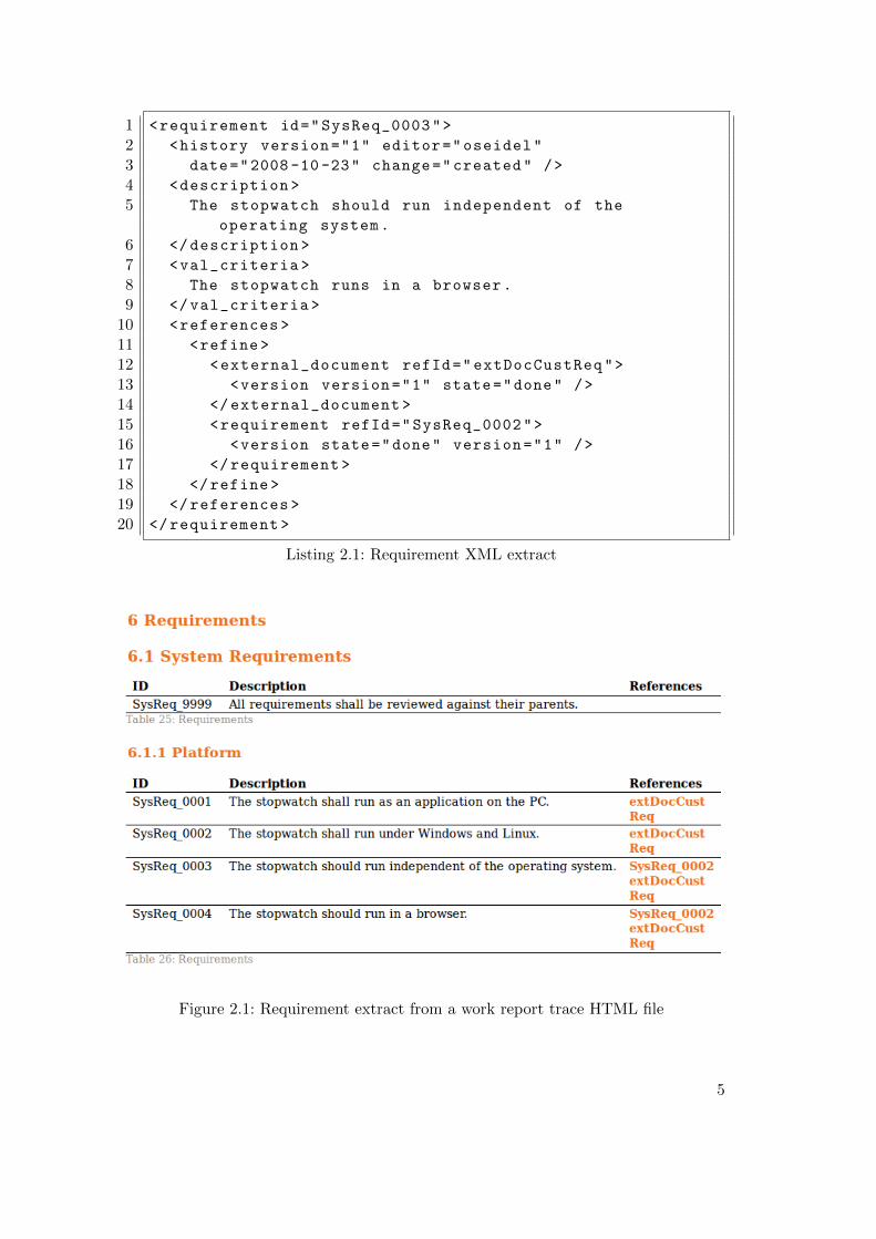
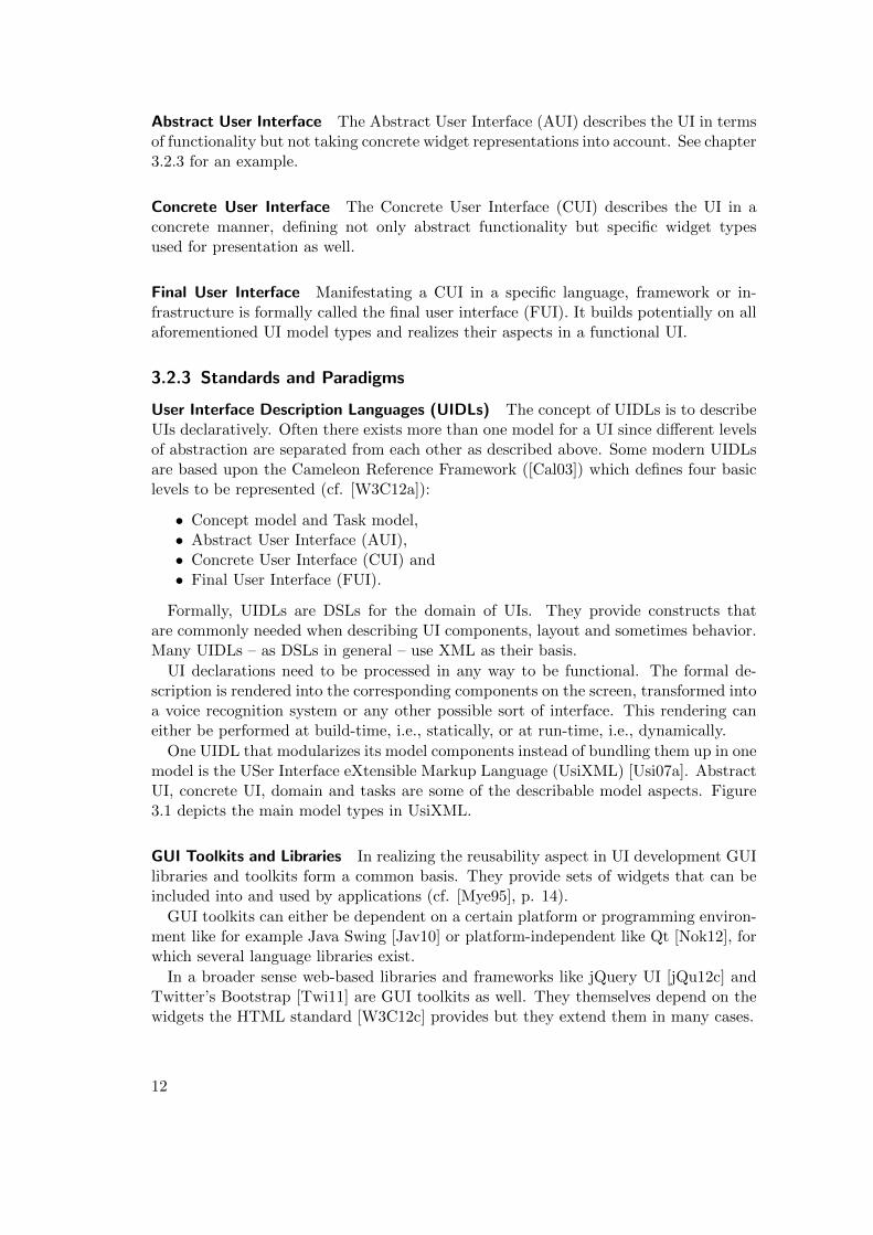
One UIDL that modularizes its model components instead of bundling them up in onemodel is the USer Interface eXtensible Markup Language (UsiXML) [Usi07a]. AbstractUI, concrete UI, domain and tasks are some of the describable model aspects. Figure3.1 depicts the main model types in UsiXML.
GUI Toolkits and Libraries In realizing the reusability aspect in UI development GUIlibraries and toolkits form a common basis. They provide sets of widgets that can beincluded into and used by applications (cf. [Mye95], p. 14).
GUI toolkits can either be dependent on a certain platform or programming environ-ment like for example Java Swing [Jav10] or platform-independent like Qt [Nok12], forwhich several language libraries exist.
In a broader sense web-based libraries and frameworks like jQuery UI [jQu12c] andTwitter’s Bootstrap [Twi11] are GUI toolkits as well. They themselves depend on thewidgets the HTML standard [W3C12c] provides but they extend them in many cases.
12
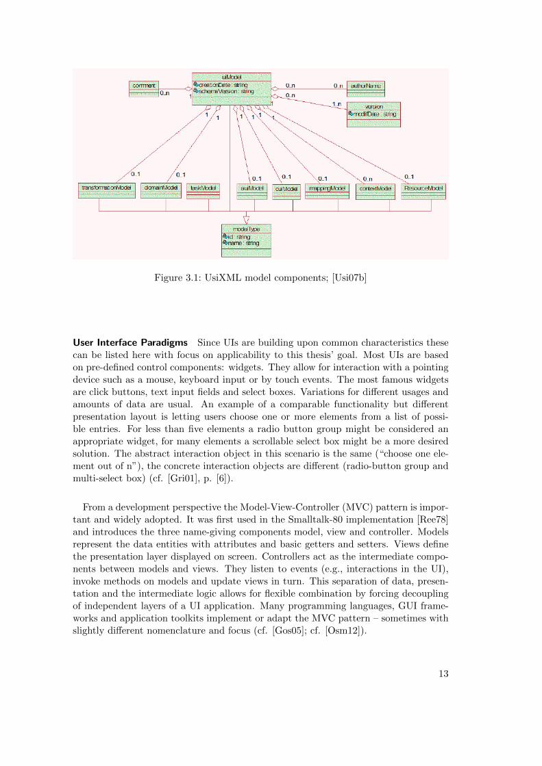
Figure 3.1: UsiXML model components; [Usi07b]
User Interface Paradigms Since UIs are building upon common characteristics thesecan be listed here with focus on applicability to this thesis’ goal. Most UIs are basedon pre-defined control components: widgets. They allow for interaction with a pointingdevice such as a mouse, keyboard input or by touch events. The most famous widgetsare click buttons, text input fields and select boxes. Variations for different usages andamounts of data are usual. An example of a comparable functionality but differentpresentation layout is letting users choose one or more elements from a list of possi-ble entries. For less than five elements a radio button group might be considered anappropriate widget, for many elements a scrollable select box might be a more desiredsolution. The abstract interaction object in this scenario is the same (“choose one ele-ment out of n”), the concrete interaction objects are different (radio-button group andmulti-select box) (cf. [Gri01], p. [6]).
From a development perspective the Model-View-Controller (MVC) pattern is impor-tant and widely adopted. It was first used in the Smalltalk-80 implementation [Ree78]and introduces the three name-giving components model, view and controller. Modelsrepresent the data entities with attributes and basic getters and setters. Views definethe presentation layer displayed on screen. Controllers act as the intermediate compo-nents between models and views. They listen to events (e.g., interactions in the UI),invoke methods on models and update views in turn. This separation of data, presen-tation and the intermediate logic allows for flexible combination by forcing decouplingof independent layers of a UI application. Many programming languages, GUI frame-works and application toolkits implement or adapt the MVC pattern – sometimes withslightly different nomenclature and focus (cf. [Gos05]; cf. [Osm12]).
13
3.2.4 Limitations
The formalization approach inherent to MBUID concepts is based on the advantagesit provides in terms of efficiency and easier maintainability. Experiences made over thelast 20 years7 show that there are some aspects limiting the usage of MBUID techniquesand mechanisms. Automation always demands for formalization and standardization(cf. [Kla06], p. 2). This implies that the generated UIs basically follow a similarsort of structure. Any “look and feel” features that are highly specific to the tasksand the domain the UI is acting upon have to be manually specified and coded ontop of a generated basis ([Gri01], p. [2]). UIs that really support the user’s taskaccomplishments and allow for efficient and context-aware usability experience needto be highly specific. To describe such specific behavior and interaction patterns in aformal model leads to contradiction in most cases. Formalization and specialization areopposites to each other and concrete interaction metaphors are hardly expressible usingformal schematization.
Exploiting existing schema and model information for automating UI developmentwill mostly lead to a form-based solution ([Sch96], p. 18) of the UI in question. Theprinciple of direct manipulation is difficult to be supported by an automated UI ap-proach. The prototypes in this thesis are highly form-based, which is acceptable for abasic functionality. Potentials for more elaborate UI techniques and paradigms exceed-ing forms as the interaction basis will be pointed out in place.
It is often stated that MBUID has not reached a main-stream level of acceptance inthe UI development and design sector ([Tra09], p. 12; [Mei11a], p. 404; [Sze96], p. xxii;cf. [Mye00], p. 10). Reasons for the lack of adaptations are the often verbose syntaxof UIDLs, the lack of out-of-the-box solutions (cf. [Mei11a], p. 404) and the contra-intuitive paradigm of formalizing UI development processes that much (cf. [Tra02], pp.12ff.).
3.3 Relation to Thesis Scope
The development of UIs as a common way of human-computer interaction is crucial toany kind of application. Considerations about general paradigms such as the usage ofmetaphors in UIs and more specific decisions on which UI widgets to choose are essen-tial when designing and implementing a UI for an application. The level of possibleformalization and the applicability of systematically generating parts of the UI influ-ences a) the (manual) implementation expense and b) the user experience provided bythe UI.
Applying these concepts to the thesis goal of possible UI prototype solutions forPrIML, the focus is on the balance between formalization, i.e., basically treating all ofthe model’s entity types in a similar way, and specialization, i.e., finding appropriatemetaphors and derived interaction patterns for each entity type. Since the model-drivenparadigm is key to this thesis the basic attempt is to automate similar steps in the UIdevelopment and to identify exemplary cases where further adjustment can improveuser experience.
7The earliest approaches in MBUID date back to the early 1990s.
14
4 Model-Based Software Development
The terms model-based software development, model-driven software development andGenerative Programming are closely related but are not considered synonyms. [Kla06]states the difference between model-based and model-driven by defining that model-based methods are not necessarily aiming for automation while model-driven approachestake models as the basis for transformations, i.e., automation processes (cf. pp. 3f.).The term Generative Programming is mainly used by [Cza04] and describes the methodof developing software with automation approaches (cf. [Kla06], p. 2). It focuses onsoftware system families rather than on single pieces of software. Usually models areused as the input of generation processes ([Kla06], p. 13) and it aims at a completeautomation (cf. [Sta07], p. 37).
Generating software (components) is relevant to this thesis because using an XMLSchema model as the basis of a UI follows the approach of automatically generatingsource code. The model is the input, the UI is the generated output. There can and shallbe no 100% automation in this thesis’ prototypes. Generators are used for repetitivesteps, manual additions and adjustments complement this generated source code.
Model-based software development can be considered to be a super-set to MBUID,since every UI is a piece of software, which is, when developed in a model-based fashion,an example of model-based software development.
4.1 Goals
Possible advantages of generating software in general are stated by [Kla06] as (cf. pp.50f.):
• consistent ID generation,• performance,• type safety and• platform independence.
Furthermore, the following goals and principles are essential to generating softwarecomponents.
4.1.1 Efficiency
Generative approaches are considered to increase efficiency because potentially onegenerator program is able to generate arbitrarily many software programs. Assumingthat the generator in question is set up appropriately it performs programming tasksin a systematic, complete and repeatable manner (cf. [Kla06], p. 141).
15
4.1.2 Consistency
Consistency is a goal that generative approaches can support by performing tasks suchas ID generation, applying naming conventions8 and ensuring the validity of referencesbetween different pieces of software.
Generally generating source code can assist programmers by completing systematicand thus automatable tasks. Generators, once set up properly, ensure consistencythroughout the components they generate (cf. [Kla06], pp. 2f.).
4.1.3 DRY (Don’t Repeat Yourself)
Rather a central principle but indirectly also a goal is the DRY principle ([Hun00],pp. 27f.). It demands to assert data and information only once and to derive furtherviews from that assertion in other contexts if necessary. The DRY principle is one ofthe crucial aspects that motivate generative programming and model-driven softwaredevelopment. Keeping information in formal representations and generating softwarebased on these models realizes the DRY principle. It applies its deduplication goal forhigher efficiency especially when information changes and evolutions occur. Consistencyand propagation of information change is ensured when obeying the DRY principle.
Abstraction is the key requirement for DRY. When centrally asserting information inorder to reuse it there has to be a shared definition, i.e., abstraction thereof. Examplesof such shared definitions are configuration files, build files and models in general.
An example of a common use case of DRY is using one domain model for severalcomponents of an application. The data base tables can be generated from it, theobjects in the application logic querying the data base, the UI components used fordisplay and manipulation and the documentation (cf. [Hun00], pp. 28f.).
4.2 Methods
The methods that are described here are common in software generation although notall of them are applicable in every Model-based software development (MBSD) use case.
Code Generators Based on models or, more generally put, formal descriptions, codegenerators create source code (cf. [Sta07], p. 12). The formal description takes the roleof a configuration for the generation process. Generation happens before the softwareis executed, i.e., at compile time. Interpreters have a similar goal as code generators:they create output based on formal descriptions, but at run-time. Since interpretersare not crucial to this thesis they are not described in depth.
Reference Implementation When generating software there exists the developmentparadigm of setting up a reference implementation as the target of the generation steps(cf. [Kla06], pp. 39ff.). The generator’s output is always compared to the referenceimplementation and it is contiuously developed “against” it. The generator’s status
8An often named example is a consistent nomenclature for get and set methods in Object-OrientedProgramming (OOP).
16
is thus transparent in all development phases and the generator’s scope is preciselycomprehensible.
Domain-Specific Languages In software development abstraction is a key componentfor distributing complexity. DSLs are often used to enable domain experts to assertinformation about the domain in a more comfortable way without having to know manytechnical details apart from domain-immanent aspects. XML is often used as the basisfor DSLs. It provides a stable syntax and a rich tool support for aspects like structuring(XML Schema, Document Type Definition (DTDs)), querying (XPath, XQuery) andtransformation (XSLT).
Model-to-Model Transformations Since in most cases step-wise generation is neces-sary there are different generators contributing to the end result (cf. [Kla06], cf. p. 6).These different generators often need models of different abstraction levels (cf. [Sta07],cf. p. 195). This makes model-to-model transformation a method frequently used byMBSD.
An example of a model-to-model transformation is the XML Schema to Ecore trans-formation in the Eclipse Modeling Framework (EMF). The input XSD(s) are iteratedand the first result is a representaton of the modelled entities expressed with the Ecoremeta-model. EMF reuses constructs of the XML Schema meta-model, expresses themwith constructs of the Ecore meta-model which contains information not directly avail-able in XML Schema. This added information can be further used by source codegenerations based on the Ecore model and would not directly have been present fromthe model expressed in XSD ([Ste09], pp. 179f.).
Templating When generating source code (or potentially any other kind of text-based content) templates are a common way of pre-defining a structure that can beparametrized with concrete values. Static content is notated as is, complemented withexpressions containing parameters and/or more complex expressions to be evaluatedand filled in during generation (cf. [Sta07], pp. 146f.). Conditional output, repeatedoutput and the invocation of other templates in order to delegate specific processingbelongs to common template functionality.
Examples of software generation systems using templating are Acceleo [Ecl12a] andXpand/ Xtend [Ecl12c]. XSLT as the main XML processing tool also uses templatesthat can either be named and called explicitly and/or that can have a matching clausecontaining XPath expressions identifying objects the template shall be applied to. In theweb development context templating mechanisms are frequently used to render HTMLfragments parametrized by (mostly) JavaScript Object Notation (JSON) [Cro02] dataand inject these produced fragments into the Document Object Model (DOM) [W3C05]tree.
Combination of Generated and Manually Written Source Code Generations arerarely used stand-alone but complemented by manually written source code. Thereexist different methods of bringing both sorts of code together (cf. [Sta07] pp. 159f.).
17
An OOP-oriented paradigm is the three-level inheritance (cf. [Sta07], p. 161). Thegenerator creates two levels automatically, the third level is manually provided by thedeveloper. Methods and attributes are inherited and potential overrides and comple-ments are applied. The generated code does not have to be manipulated by developersto fit specific needs.
Another paradigm which is widely used, for example in EMF (see chapter 5.2.2), areprotected source code zones. These are marked with e.g. special comments and willnot be overwritten in new generation runs. Since EMF for example is Java-based, itexploits JavaDoc comments and takes @generated tags into account. Whenever nosuch tag is present or is changed to @generated NOT the respective source code block isprotected. This protection practice is criticized for intermixing source code irreversiblyand complicating maintenance (cf. [Sta07], p. 160).
4.3 Relation to Thesis Scope
Closely related to the MBUID paradigm described above, the more general approach ofMBSD plays a key role in this thesis scope. Generating software components, namelyUI components, from formal descriptions is the goal of the thesis. Evaluating differentways of applying such methods on XSD file collections and demonstrating possibilitiesfor a potentially generic and adaptable approach is the connection between the conceptsdescribed in this section above and the thesis as a whole.
Generation steps are the connection between models (be it a domain model or aUI model as a special case) and source code. Many MBUID systems lack normativegeneration/ transformation processes and leave this to specific implementations. Thisis one limiting aspect of MBUID adaption in UI development (cf. chapter 3.2.4).
18
5 Modelling
Modelling9 is a broad field and referenced in many research and practice contexts. Itis based on the concept of a model which in most cases is defined as a description of asimplified part of reality (cf. [Kla06], pp. 12f.; cf. [Del07], pp. 10f.).
MBSD and MBUID approaches as described above require models as their configu-ration input; that makes modelling in general and XML Schema modelling specifically(since it is used for the PrIML vocabulary definition) an essential part of this thesis’considerations.
5.1 Languages and Standards
Since describing models is an abstract process there have to be methods and toolsfor making the results of modelling explicit. Declaratively asserting information aboutmodels demands for languages enabling modellers to express the main types of modellingproperties (also see chapter 5.2 and cf. [Ste09], p. 17; cf. [OMG11a], p. 8):
• Classes,• Attributes,• References,• Cardinalities and• Constraints.
Visualizing models is often used for presentation and human reception.
5.1.1 Unified Modeling Language
In order to increase standardization in modelling and to explicitly meta-model (cf.chapter 5.2) the components commonly reused in modelling processes the Object Man-agement Group (OMG) developed the Unified Modeling Language (UML) standard (cf.[OMG11b]). It received broad adaptation for modelling issues in various domains suchas software development.
UML is not within the focus of this thesis, which is the reason for not explaining itfurther.
5.1.2 XML-Related Standards
Especially for modelling XML-based languages (also called XML dialects) there existstandards reflecting the specific XML features. Such features include the distinctionbetween elements and attributes, usage of namespaces and XML entities. The two
9This thesis uses the spelling modelling, not modeling ; exceptions are direct citations and productnames.
19
basic approaches of declaring XML dialect structures are schema languages that arethemselves expressed with XML (XML Schema, RELAX NG and Schematron) andnon-XML-based languages (DTDs).
Attempts to convert XML declaration standard descriptions are made by tools suchas Trang [Cla08]. It takes an input definition (in one of the formats RELAX NG (XMLsyntax), RELAX NG (compact syntax), DTD or XML instance file) and transforms itinto the desired output schema language. Possible outputs are both RELAX NG syntaxstandards, DTD and XML Schema.
DTD XML is a subset of the more generic Standard Generalized Markup Language(SGML) [W3C95] standard for defining markup languages (cf. [W3C08]). To declare anSGML-conform markup language there exists the DTD standard. It enables modellersto define a grammar asserting the permitted structure of instance documents conformingto the DTD (cf. [W3C08]). The components of a DTD are element definitions and itscardinalitites, attribute definitions and XML entity definitions. DTDs themselves arenot XML-based but introduce a grammar syntax of their own. The reusability ofcomponents is not supported, which can lead to repetitive assertions when designingDTDs. Furthermore, DTDs are namespace-unaware (cf. [Wik12b]), which limits theirpotential use cases when vocabulary combination is needed.
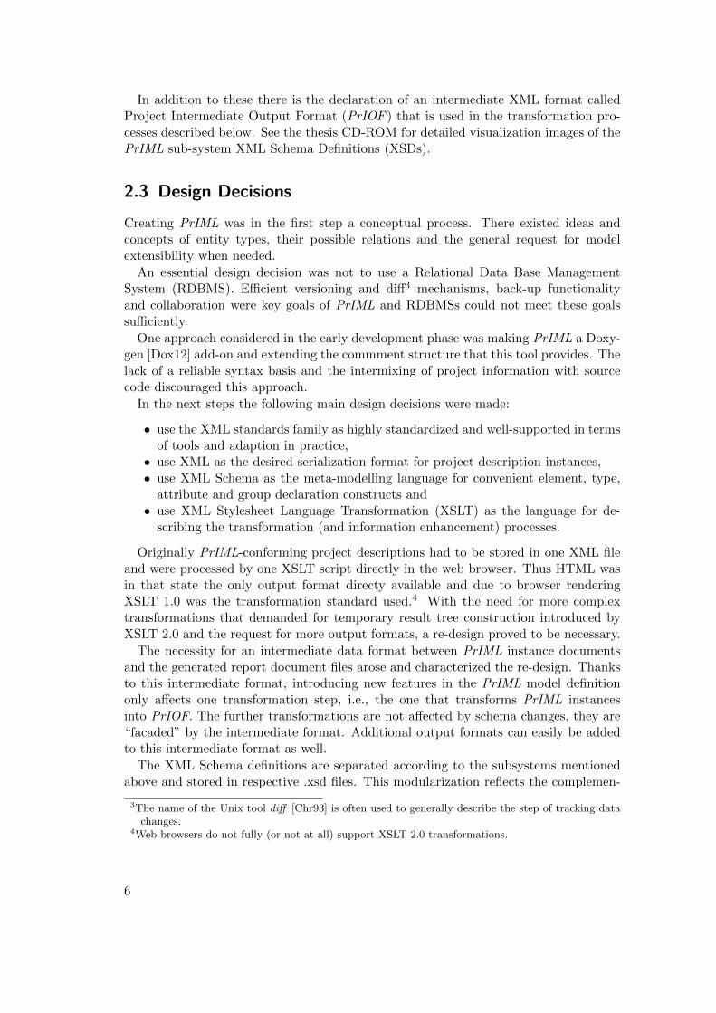
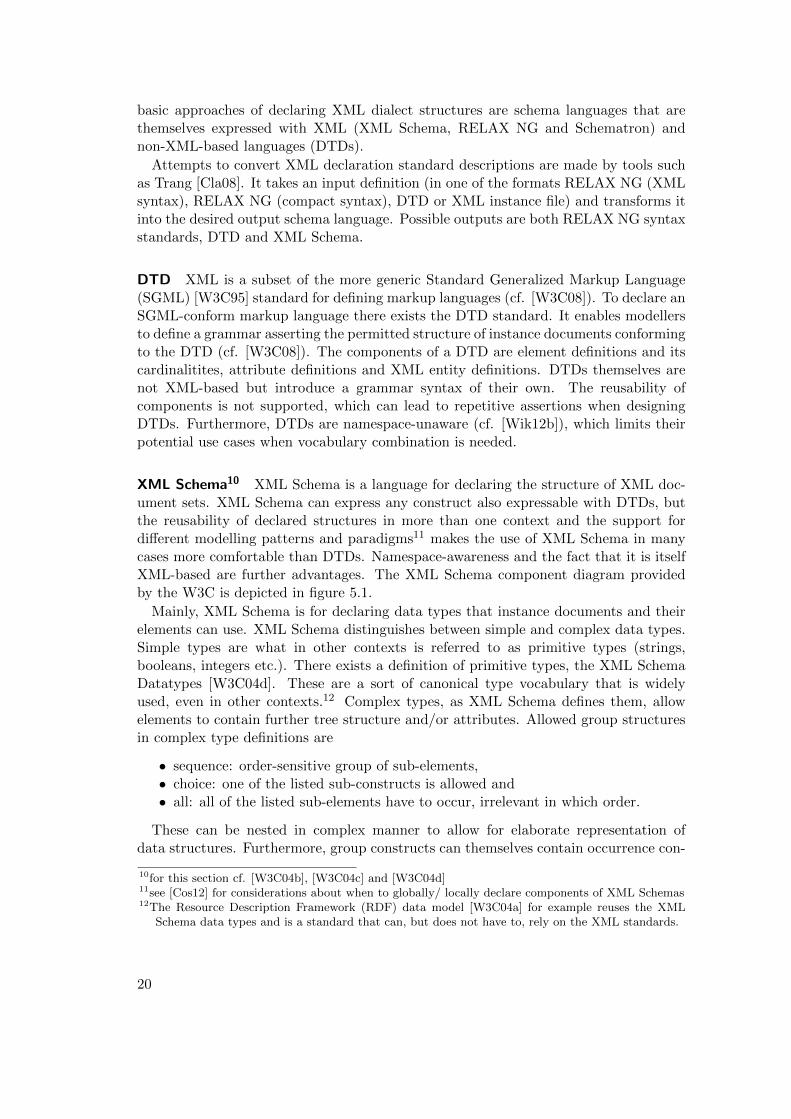
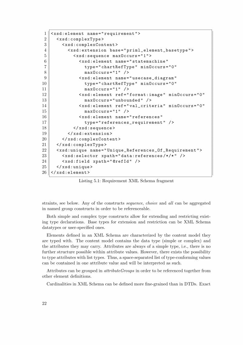
XML Schema10 XML Schema is a language for declaring the structure of XML doc-ument sets. XML Schema can express any construct also expressable with DTDs, butthe reusability of declared structures in more than one context and the support fordifferent modelling patterns and paradigms11 makes the use of XML Schema in manycases more comfortable than DTDs. Namespace-awareness and the fact that it is itselfXML-based are further advantages. The XML Schema component diagram providedby the W3C is depicted in figure 5.1.
Mainly, XML Schema is for declaring data types that instance documents and theirelements can use. XML Schema distinguishes between simple and complex data types.Simple types are what in other contexts is referred to as primitive types (strings,booleans, integers etc.). There exists a definition of primitive types, the XML SchemaDatatypes [W3C04d]. These are a sort of canonical type vocabulary that is widelyused, even in other contexts.12 Complex types, as XML Schema defines them, allowelements to contain further tree structure and/or attributes. Allowed group structuresin complex type definitions are
• sequence: order-sensitive group of sub-elements,• choice: one of the listed sub-constructs is allowed and• all: all of the listed sub-elements have to occur, irrelevant in which order.
These can be nested in complex manner to allow for elaborate representation ofdata structures. Furthermore, group constructs can themselves contain occurrence con-
10for this section cf. [W3C04b], [W3C04c] and [W3C04d]11see [Cos12] for considerations about when to globally/ locally declare components of XML Schemas12The Resource Description Framework (RDF) data model [W3C04a] for example reuses the XML
Schema data types and is a standard that can, but does not have to, rely on the XML standards.
20
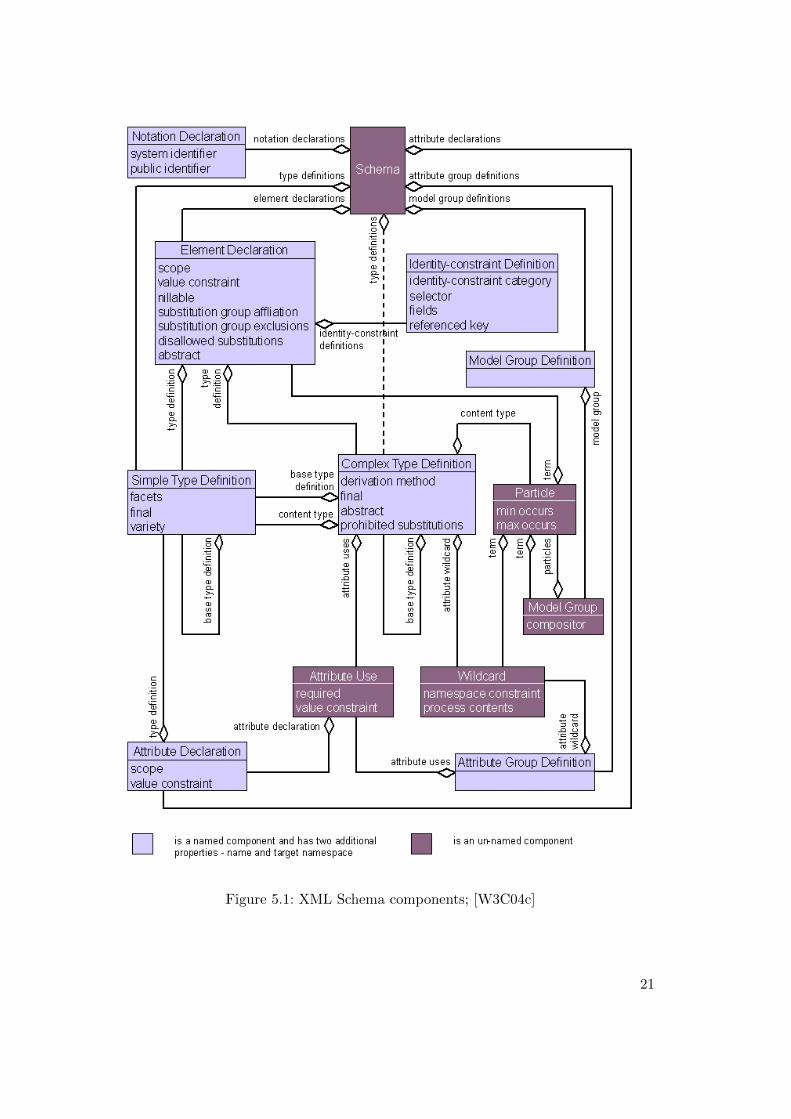
Figure 5.1: XML Schema components; [W3C04c]
21
1 <xsd:element name="requirement">
2 <xsd:complexType >
3 <xsd:complexContent >
4 <xsd:extension base="priml_element_basetype">
5 <xsd:sequence maxOccurs="1">
6 <xsd:element name="statemachine"
7 type="chartRefType" minOccurs="0"
8 maxOccurs="1" />
9 <xsd:element name="usecase_diagram"
10 type="chartRefType" minOccurs="0"
11 maxOccurs="1" />
12 <xsd:element ref="format:image" minOccurs="0"
13 maxOccurs="unbounded" />
14 <xsd:element ref="val_criteria" minOccurs="0"
15 maxOccurs="1" />
16 <xsd:element name="references"
17 type="references_requirement" />
18 </xsd:sequence >
19 </xsd:extension >
20 </xsd:complexContent >
21 </xsd:complexType >
22 <xsd:unique name="Unique_References_Of_Requirement">
23 <xsd:selector xpath="data:references /*/*" />
24 <xsd:field xpath="@refId" />
25 </xsd:unique >
26 </xsd:element >
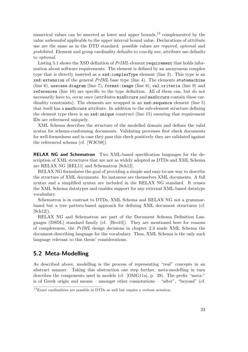
Listing 5.1: Requirement XML Schema fragment
straints, see below. Any of the constructs sequence, choice and all can be aggregatedin named group constructs in order to be referenceable.
Both simple and complex type constructs allow for extending and restricting exist-ing type declarations. Base types for extension and restriction can be XML Schemadatatypes or user-specified ones.
Elements defined in an XML Schema are characterized by the content model theyare typed with. The content model contains the data type (simple or complex) andthe attributes they may carry. Attributes are always of a simple type, i.e., there is nofurther structure possible within attribute values. However, there exists the possibilityto type attributes with list types. Thus, a space-separated list of type-conforming valuescan be contained in one attribute value and will be interpreted as such.
Attributes can be grouped in attributeGroups in order to be referenced together fromother element definitions.
Cardinalities in XML Schema can be defined more fine-grained than in DTDs. Exact
22
numerical values can be asserted as lower and upper bounds,13 complemented by thevalue unbounded applicable to the upper interval bound value. Declarations of attributeuse are the same as in the DTD standard: possible values are required, optional andprohibited. Element and group cardinality defaults to exactly one, attribute use defaultsto optional.
Listing 5.1 shows the XSD definition of PrIML element requirement that holds infor-mation about software requirements. The element is defined by an anonymous complextype that is directly inserted as a xsd:complexType element (line 2). This type is anxsd:extension of the general PrIML base type (line 4). The elements statemachine
(line 6), usecase diagram (line 7), format:image (line 8), val criteria (line 9) andreferences (line 10) are specific to the type definition. All of them can, but do notnecessarily have to, occur once (attributes minOccurs and maxOccurs contain these car-dinality constraints). The elements are wrapped in an xsd:sequence element (line 5)that itself has a maxOccurs attribute. In addition to the sub-element structure definingthe element type there is an xsd:unique construct (line 15) ensuring that requirementIDs are referenced uniquely.
XML Schema describes the structure of the modelled domain and defines the validsyntax for schema-conforming documents. Validating processes first check documentsfor well-formedness and in case they pass this check positively they are validated againstthe referenced schema (cf. [W3C08]).
RELAX NG and Schematron Two XML-based specification languages for the de-scription of XML structures that are not as widely adopted as DTDs and XML Schemaare RELAX NG [REL11] and Schematron [Sch12].
RELAX NG formulates the goal of providing a simple and easy-to-use way to describethe structure of XML documents. Its instances are themselves XML documents. A fullsyntax and a simplified syntax are included in the RELAX NG standard. It reusesthe XML Schema datatypes and enables support for any external XML-based datatypevocabulary.
Schematron is in contrast to DTDs, XML Schema and RELAX NG not a grammar-based but a tree pattern-based approach for defining XML document structures (cf.[Sch12]).
RELAX NG and Schematron are part of the Document Schema Definition Lan-guages (DSDL) standard family (cf. [Bro10]). They are mentioned here for reasonsof completeness, the PrIML design decisions in chapter 2.3 made XML Schema thedocument-describing language for the vocabulary. Thus, XML Schema is the only suchlanguage relevant to this thesis’ considerations.
5.2 Meta-Modelling
As described above, modelling is the process of representing “real” concepts in anabstract manner. Taking this abstraction one step further, meta-modelling in turndescribes the components used in models (cf. [OMG11a], p. 29). The prefix “meta-”is of Greek origin and means – amongst other connotations – “after”, “beyond” (cf.
13Exact cardinalities are possible in DTDs as well but require a verbose notation.
23
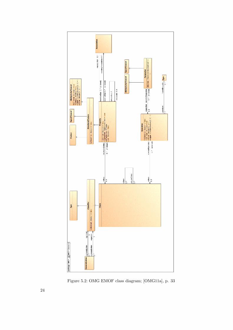
Figure 5.2: OMG EMOF class diagram; [OMG11a], p. 33
24
[Lid12]). It is a common prefix to express an increased level of abstraction comparedto the term prefixed.
The languages used to describe models such as UML and XML Schema are themselvesmodels containing components which form the basis for modelling. Thus they arereferred to as meta-models. Taking the abstraction even further, models that describethe structure (i.e., the common features) of meta-models are called meta-meta-models.Although there is theoretically no limit for ever-further abstraction (cf. [Sta07], p. 62),meta-meta-models are usually described with their own concepts and thus the meta-meta-model is the most abstract level explicitly described (cf. [Sta07], p. 31; cf. [Ste09],p. 17). The most prominent meta-meta-model is OMG’s Meta Object Facility (MOF).Ecore from the EMF context is its own meta-meta-model ([Ste09], p. 17).
5.2.1 Meta Object Facility
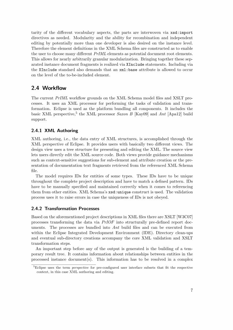
From the OMG standardization consortium [OMG12] responsible for standards likeUML and XML Metadata Interchange (XMI) comes a meta-model called MOF. Figure5.2 depicts the entity types described by OMG’s Essential MOF (EMOF) meta-model.
It is not further described because of its lack of applicability but see the similaritiesto EMF’s Ecore below.
5.2.2 Eclipse Modeling Framework and Ecore
In the context of the Eclipse IDE there is the EMF project dealing with modelling,model standard integration and model-driven Java application building (cf. [Ste09], p.xxiii). It has reached a good industry adoption and forms the basis for further UI andgeneral software development steps. Thus it enables the integration of modelling andprogramming (cf. [Ste09], pp. 15f.).
The core of EMF is the standard Ecore. It is a meta-model that integrates UML, Ra-tional Rose, XML and Java (cf. [Ste09] p. xxiii, p. 14). Mappings from XML Schema toEcore, UML to Ecore and vice versa respectively make model-to-model-transformationsand model-to-code-transformations possible. Furthermore EMF provides mechanismsfor generating Eclipse-based editors conforming to the underlying model. Such editorsare functional Eclipse plugins that enable users to Create, Retrieve, Update and Delete(CRUD) model-conforming data instances.
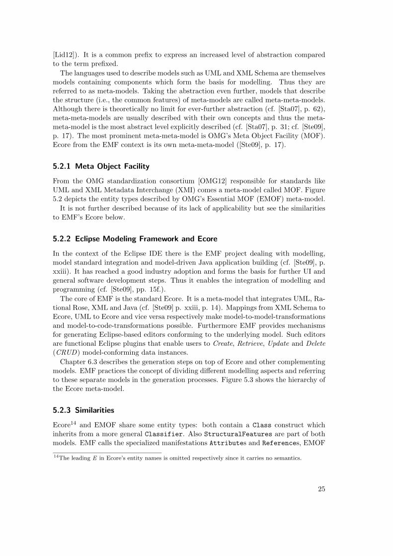
Chapter 6.3 describes the generation steps on top of Ecore and other complementingmodels. EMF practices the concept of dividing different modelling aspects and referringto these separate models in the generation processes. Figure 5.3 shows the hierarchy ofthe Ecore meta-model.
5.2.3 Similarities
Ecore14 and EMOF share some entity types: both contain a Class construct whichinherits from a more general Classifier. Also StructuralFeatures are part of bothmodels. EMF calls the specialized manifestations Attributes and References, EMOF
14The leading E in Ecore’s entity names is omitted respectively since it carries no semantics.
25
Figure 5.3: Ecore meta-model hierarchy; [Ecl06b]
calls it Property. Operations and its Parameters are another similarity in the con-structs of both models.
Ecore has a practical use case, i.e., forming the basis for mappings to XML Schema,UML and especially Java, EMOF does not directly target such a specific use case.
5.3 Relation to Thesis Scope
The approach of generating UI components requires information about the nature ofthese components. Which kinds of widgets have to be generated and in which way theentity types of the underlying domain relate to each other is necessary for the generationprocesses. Models like the PrIML XSDs contain this sort of information and are usedas the parametrization for the code generators.
Meta-modelling and meta-meta-modelling are relevant to this thesis because when-ever models and modelling languages (e.g. XML Schema) are used, their structuredetermines the expressivity of the models described.
26
6 Practical Solution Approaches
The implementation described in this thesis can be formally expressed as the attemptto weave together different transformation and generation steps that produce editorsfor XML Schema-defined DSLs. PrIML is used as the concrete example of such anXML Schema-based DSL. The goal of this chapter is the description of two differentprototypes of semi-automatically developed tools for CRUD operations on XML dataconforming to the source schema.
Using the conceptual and technical basis of the chapters above this chapter describesthe process of choosing the development and runtime framework, the steps taken in thecode generation processes and the manual adjustment aspects. Two different approachesare taken to achieve the goal just described: a browser-based HTML / Cascading StyleSheets (CSS) /JavaScript MVC application and an EMF/ Extended Editing Framework(EEF) Eclipse plugin. The prototypes have been developed in the thesis period by theauthor. The thesis CD-ROM contains screen casts demonstrating the processes and thegenerated prototypes complementing the descriptions of this chapter and the detailedexplanations in appendix A.
Being able to compare is the most important reason for choosing these two parts inthe thesis’ practical development instead of focusing on only one of them. EMF andthe accompanying standards are the example use case for using an existing modellingand generation framework with very high abstraction and several levels of softwarecomponents interacting with each other. Forming a concept and manifesting it in self-developed generation processes for a web application is the complementary approach –it focuses on light-weight development paradigms. Understanding and using externalcode generators on the one hand and developing own code generators on the other handare the two aspects this thesis’ chapter demonstrates. In case of the web applicationdevelopment aspect of this chapter there are always two layers of interest that have to beconsidered: a) the desired architecture of the output application and b) the necessitiesfor the generator functions creating the application components. It needs to be clearwhat features the application shall have and how they are achievable in order to setup the generator appropriately. These sorts of concepts already exist for EMF/EEF;following and comprehending rather than reinventing this given abstraction hierarchyis essential when using EMF and EEF.
When developing the concepts for the prototypes, the idea of using a UIDL (seechapter 3.2.3) came to mind. Reasons for not using UIDL concepts and languageswere:
• anticipated extra costs in terms of several needed transformation steps (accordingto the author’s brief considerations)
– XML Schema to AUI,– AUI to CUI and
27
– CUI to FUI• the lack of a real benefit, since the often-mentioned reuse paradigm does (at
least in the direct thesis scope) not apply; EMF/EEF uses its own models andtransformation methods and a UIDL is not needed or supported there.
Picking up the working hypothesis that an XML Schema provides enough informationfor a UI, using a UIDL such as the briefly described UsiXML (see chapter 3.2.3) isomitted and processes directly working with XML Schema information – or directlyderived information – are chosen. A transformation of XML Schema constructs to AUIelements is surely contained in the generation processes of both practical solutions, butit is not explicitly expressed separately from the final UI components. An examplefor such implicit transformations is the design decision to integrate simple-typed sub-elements of an element type and attributes (that are by definition simple-typed) intoobject properties. The mechanism of representing elements with an enumeration simpletype as “select one of n” interaction objects that are manifested as drop-down menusin the UI is another example for skipping an explicit AUI abstraction layer.
6.1 Requirements for User Interface Solution
The analysis of PrIML’s current state and its workflow integration as well as the researchon common practices in generative (UI component) programming led to two appropriateprototype solutions. The decision to compare two different approaches has the followingreasons:
• it forms a concrete demonstration case for the ability to generate different ap-plication prototypes out of one source model and hence stresses an advantageaspect of model-based methods,• each of the two approaches can illustrate individual aspects of generation processes
and• one approach reuses an existing code generator framework, the other one is a
manually developed generator combination.
These three main aspects enable a broader and more manifold perspective on generat-ing UI components and the underlying concepts and design decisions that are possible.
The requirements for a PrIML user interface and its generation are:15
• The UI is able to run on Windows, Linux and MacOS X• The UI is generated as completely as possible; manual customizations can be
applied to fit needs more exactly• Schema changes are reflected in the UI after a regeneration• Manual customizations are protected from being overwritten by a regeneration• The user does not need to enter XML markup• The user can combine XML data entry and UI-based data entry• The UI suggests components and/or values where applicable
15These were gathered by the ISCUE management and staff together with the author at the beginning ofthe thesis period as the basic requirement set. Potential refinements are described in the EMF/EEFchapter.
28
• The UI allows user to deep-copy (and manually adjust) existing components• The UI provides undo and redo functionality• Approaches of direct manipulation (e.g., drag&drop) are enabled where applicable• Element values of mixed content type (especially format:formattedText and its
sub-types) can be entered with an appropriate rich text editor widget• PrIML’s XSLT processes can be invoked from the UI
The following two chapters 6.2 and 6.3 describe the characteristics of the two ap-proaches taken. Similarities and differences between them are pointed out in chapter6.4. It will also be discussed to what extent the requirements stated above can be metby the two solutions.
6.2 Browser-Based Application
Applications that run in web browsers build on technologies that exist for several yearsbut have evolved much since then (cf. [Mac11b], p. 1). The most important languagesand paradigms are defined first in order to allow for a better comprehensibility.
HTML(5) and CSS(3) HTML is the basic markup language for hypertext documentsand its latest development version is 5. The W3C is mainly responsible for its state,drafts and Application Programming Interfaces (APIs). HTML5 [W3C12b] targets agreater flexibility in terms of syntactical constructs, introduces language elements forbetter semantic markup reflection (section, article, etc.) and provides APIs for e.g.client-side data storage and canvas-based graphics rendering. While HTML is respon-sible for the markup, structure and content of web pages, CSS provides constructs forstyling these elements. Positioning, visibility, colors, borders and the appearance ofform elements are key components of this style sheet standard. There exist libraries forcross-browser support and richer features in the style sheet context as well – Syntacti-cally Awesome Stylesheets (SASS) [Cat12], LESS [Sel12] and Stylus [Sty12] are someof the attempts to create super-sets of CSS and enriching it with variable support,function definitions and thus a higher reusability and consistency.
JavaScript/ECMAScript/CoffeeScript JavaScript is a scripting language originallyonly used for singular use cases of letting a web page respond to events or dynami-cally change content. With its standardization as ECMAScript [ECM12] it could gainimportance over the years and is by now the most essential programming language inclient-side web development. Other languages such as CoffeeScript [Cof11] are designedas super-sets of JavaScript, introducing syntax shortcuts, providing a native class sup-port that JavaScript itself lacks and offering a clearer syntax in general. CoffeeScriptcompiles into JavaScript and is becoming popular in web application development (cf.[O’G12]).
Document Object Model and JavaScript Frameworks The aspect of dynamicallychanging web page content in reaction to user interaction (events) and data updatesmakes access to the page’s structure necessary. The W3C standard DOM encapsules
29
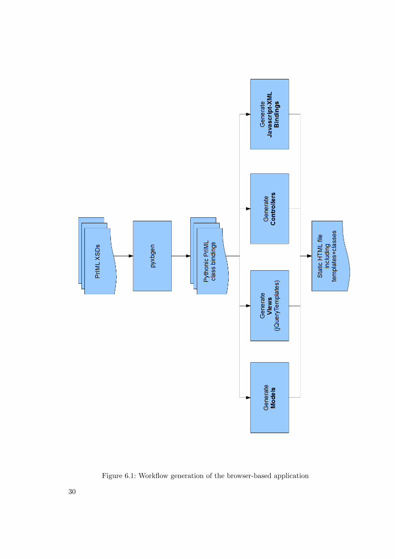
Figure 6.1: Workflow generation of the browser-based application
30
the HTML page structure and allows access via a JavaScript API. Every browser enginesupports its own manipulation methods and uses a different nomenclature. For the in-tegration and consistent access methods there are JavaScript framework libraries suchas Prototype [Pro12], mootools [moo12] or the wide-spread jQuery [jQu12a] that intro-duce an intermediate abstraction layer. The API they provide is internally mapped tothe specific browser engines and versions available and is thus hiding these differencesfrom the developer.
AJAX and JSON For asynchronous communication between server and client sideJavaScript provides XMLHTTPRequests [W3C11b]. As with DOM manipulation, everybrowser has slightly different notions and syntax conventions. jQuery for example offerscomfortable ways for wrapping these specifica. The paradigm of asynchronous requestsfrom the client to the server, the mechanisms of reacting to responses and the processingof these data responses in callback functions is called Asynchronous JavaScript andXML (AJAX). Originally XML was the designated serialization format because of itsstandardized syntax and wide-spread tool support. Over the years the advantages ofthe more light-weight and immediately JavaScript-digestible JSON serialization format[Cro02] has lead to often JSON-focused AJAX transfers.
Model-View-Controller on client-side The evolution of web pages to often fully fea-tured applications in the browser raises the necessity of software architecture, especiallyon the client-side. Since for example PHP Homepage Pre-Processor (PHP) and Rubydevelopment libraries already support the MVC paradigm for some time (cf. [Zen12];cf. [Han12]) it became only recently common on the client-side to apply architecturalconcepts. The needs for maintainabilty, stability and flexibility apply for web appli-cations as well as for native client software (cf. [Mac11b], p. 2). In the last yearsmany MVC libraries for JavaScript were developed with comparable concepts but withdifferent levels of formalization (cf. [Osm12]). Spine [Mac12] and Backbone [Doc12] forexample are more light-weight than frameworks such as ExtJS [Sen12].
These standards briefly defined above form the general basis for (especially the client-side of) web applications. The prototype introduced in this chapter builds on top ofthem as well and adds the aspect of how to generate many parts of such an applicationbased on the existing PrIML XSDs. The desired architecture is the MVC paradigm,Spine and Backbone are both adapted. Spine is itself written in CoffeeScript andthus seamlessly supports CoffeeScript, it is the scripting language of choice for theSpine components. Backbone (and specifically the extension Backbone-relational, thatis used in the prototype) has reported limitations in supporting CoffeeScript, henceJavaScript is also a target generation language. As stated before, the graphical andusability aspect of the application is not the main focus, the development is designedto be a proof of concept for generating models, views and templates in order to havea working interface. Another goal of the web application is to demonstrate the powerof client-side applications – the prototype does not need a server side in order to befunctional. For persistence reasons a server side would become necessary but the current
31
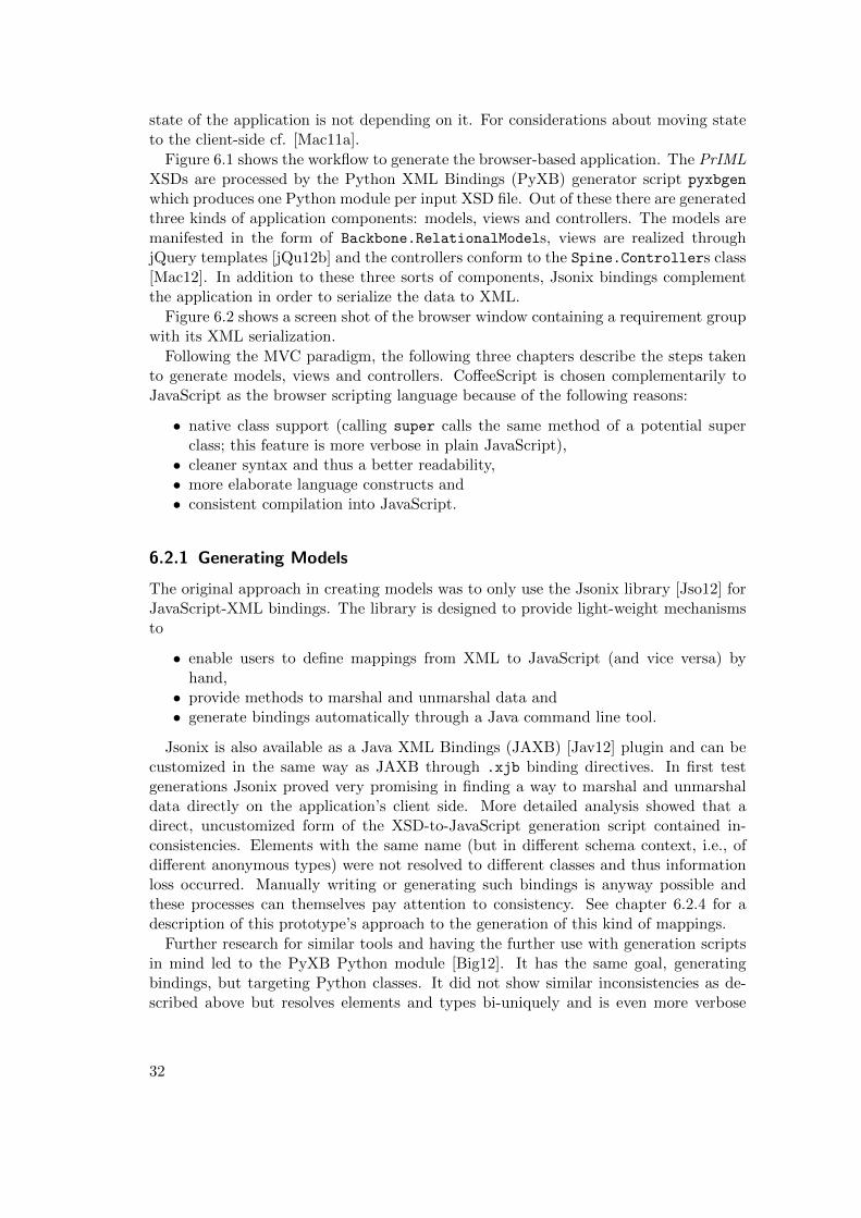
state of the application is not depending on it. For considerations about moving stateto the client-side cf. [Mac11a].
Figure 6.1 shows the workflow to generate the browser-based application. The PrIMLXSDs are processed by the Python XML Bindings (PyXB) generator script pyxbgen
which produces one Python module per input XSD file. Out of these there are generatedthree kinds of application components: models, views and controllers. The models aremanifested in the form of Backbone.RelationalModels, views are realized throughjQuery templates [jQu12b] and the controllers conform to the Spine.Controllers class[Mac12]. In addition to these three sorts of components, Jsonix bindings complementthe application in order to serialize the data to XML.
Figure 6.2 shows a screen shot of the browser window containing a requirement groupwith its XML serialization.
Following the MVC paradigm, the following three chapters describe the steps takento generate models, views and controllers. CoffeeScript is chosen complementarily toJavaScript as the browser scripting language because of the following reasons:
• native class support (calling super calls the same method of a potential superclass; this feature is more verbose in plain JavaScript),• cleaner syntax and thus a better readability,• more elaborate language constructs and• consistent compilation into JavaScript.
6.2.1 Generating Models
The original approach in creating models was to only use the Jsonix library [Jso12] forJavaScript-XML bindings. The library is designed to provide light-weight mechanismsto
• enable users to define mappings from XML to JavaScript (and vice versa) byhand,• provide methods to marshal and unmarshal data and• generate bindings automatically through a Java command line tool.
Jsonix is also available as a Java XML Bindings (JAXB) [Jav12] plugin and can becustomized in the same way as JAXB through .xjb binding directives. In first testgenerations Jsonix proved very promising in finding a way to marshal and unmarshaldata directly on the application’s client side. More detailed analysis showed that adirect, uncustomized form of the XSD-to-JavaScript generation script contained in-consistencies. Elements with the same name (but in different schema context, i.e., ofdifferent anonymous types) were not resolved to different classes and thus informationloss occurred. Manually writing or generating such bindings is anyway possible andthese processes can themselves pay attention to consistency. See chapter 6.2.4 for adescription of this prototype’s approach to the generation of this kind of mappings.
Further research for similar tools and having the further use with generation scriptsin mind led to the PyXB Python module [Big12]. It has the same goal, generatingbindings, but targeting Python classes. It did not show similar inconsistencies as de-scribed above but resolves elements and types bi-uniquely and is even more verbose
32
Figure 6.2: Web application screen shot
33
when it comes to reflecting cardinalities and grouping in the XSD definitions. Furtheradvantages are a) Python’s convenient mechanisms for inspecting its own structures(i.e., modules, classes, etc.) as an elegant basis for further generation steps and b) thefact that Python is more and more widely adapted as a server-side scripting languagein web applications.
The author developed the Python module pyxb to mvc web app with the processesand methods necessary for generating the models as extensions of RelationalModel
out of the Python classes provided by PyXB. A two-fold process was applied:
1. resolving a Python dictionary which directly reflects the (potentially deeply nested)XML Schema groups, elements, attributes, their cardinalities and fixed/ defaultvalues and
2. flattening these dictionaries into structures that provides a list of possible childelements and attributes with their “acummulated” minOccurs computed as theproduct of all minOccurs from the respective element up to the root XSD groupand the maxOccurs computed analogously (any unbounded value for a maxOccurs
turns the end result into unbounded)
Flattening the constructs from XSD leads to informatin loss since a flat element-attribute list does not in all cases reflect the expressivity that XML Schema’s groupingmechanisms provide, especially in combination with the cardinalities applicable on al-most all construct levels. Accummulating the cardinalities (see listing 6.1) transportsmost of the original cardinality information, but the order of groups is an aspect that islost by the flattening. This trade-off is made in order to prevent the processes and theresulting UI from becoming too cumbersome and verbose. Reflecting every group andcardinality detail in the UI would possibly create contra-intuitive widget combinationssince the group level of XSDs is not designated to be explicitly perceived by end users.This simplification thus is a method of hiding originally existing complexity from the UIuser – the generation processes do need to handle the full complexity to such a degreeas the flattening needs to be applied to the original complex structures.
A model is created for each complex XML Schema type and each such model is anextension of Backbone.RelationalModel. Within a model class every simple-typedsub-element and every attribute of the flattened structure derived from XSD leadsto a data field. Complex-typed sub-elements are reflected as relations linking to therespective sub-element’s model class. The model for the requirement group is shownin listing 6.2 (see appendix A.1.2 for explanations on nomenclatures for anonymoustypes).
6.2.2 Generating Views
In light-weight web development libraries such as Spine, MVC-conforming views areoften HTML fragments rendered into the DOM (cf. [Mac12]). These fragments canbe represented by templates (cf. chapter 4.2), in this case jQuery templates. Theseoffer common template functionality such as conditional rendering of content, invokingother templates for rendering sub-parts and loop constructs. There are basically twoways of storing jQuery templates: a) in script elements of their own, marked with atype="text/x-jquery-tmpl" attribute in order to distinguish them from usual Java-
34
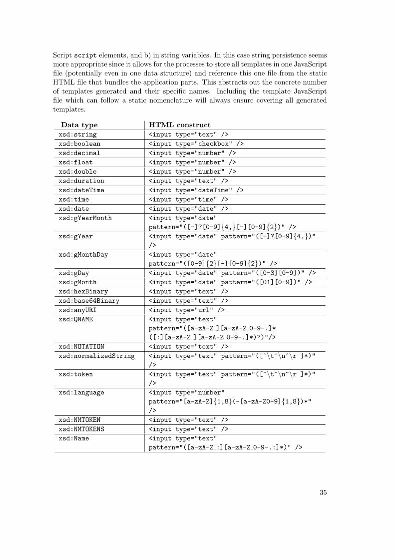
Script script elements, and b) in string variables. In this case string persistence seemsmore appropriate since it allows for the processes to store all templates in one JavaScriptfile (potentially even in one data structure) and reference this one file from the staticHTML file that bundles the application parts. This abstracts out the concrete numberof templates generated and their specific names. Including the template JavaScriptfile which can follow a static nomenclature will always ensure covering all generatedtemplates.
Data type HTML construct
xsd:string <input type="text" />
xsd:boolean <input type="checkbox" />
xsd:decimal <input type="number" />
xsd:float <input type="number" />
xsd:double <input type="number" />
xsd:duration <input type="text" />
xsd:dateTime <input type="dateTime" />
xsd:time <input type="time" />
xsd:date <input type="date" />
xsd:gYearMonth <input type="date"
pattern="([-]?[0-9]{4,}[-][0-9]{2})" />
xsd:gYear <input type="date" pattern="([-]?[0-9]{4,})"/>
xsd:gMonthDay <input type="date"
pattern="([0-9]{2}[-][0-9]{2})" />
xsd:gDay <input type="date" pattern="([0-3][0-9])" />
xsd:gMonth <input type="date" pattern="([01][0-9])" />
xsd:hexBinary <input type="text" />
xsd:base64Binary <input type="text" />
xsd:anyURI <input type="url" />
xsd:QNAME <input type="text"
pattern="([a-zA-Z ][a-zA-Z 0-9-.]*
([:][a-zA-Z ][a-zA-Z 0-9-.]*)?)"/>
xsd:NOTATION <input type="text" />
xsd:normalizedString <input type="text" pattern="([^\t^\n^\r ]*)"
/>
xsd:token <input type="text" pattern="([^\t^\n^\r ]*)"
/>
xsd:language <input type="number"
pattern="[a-zA-Z]{1,8}(-[a-zA-Z0-9]{1,8})*"/>
xsd:NMTOKEN <input type="text" />
xsd:NMTOKENS <input type="text" />
xsd:Name <input type="text"
pattern="([a-zA-Z :][a-zA-Z 0-9-.:]*)" />
35
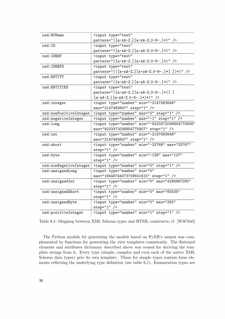
xsd:NCName <input type="text"
pattern="([a-zA-Z ][a-zA-Z 0-9-.]*)" />
xsd:ID <input type="text"
pattern="([a-zA-Z ][a-zA-Z 0-9-.]*)" />
xsd:IDREF <input type="text"
pattern="([a-zA-Z ][a-zA-Z 0-9-.]*)" />
xsd:IDREFS <input type="text"
pattern="(([a-zA-Z ][a-zA-Z 0-9-.]*[ ])*)" />
xsd:ENTITY <input type="text"
pattern="([a-zA-Z ][a-zA-Z 0-9-.]*)" />
xsd:ENTITIES <input type="text"
pattern="([a-zA-Z ][a-zA-Z 0-9-.]*([ ]
[a-zA-Z ][a-zA-Z 0-9-.]*)*)" />
xsd:integer <input type="number" min="-2147483648"
max="2147483647" step="1" />
xsd:nonPositiveInteger <input type="number" max="0" step="1" />
xsd:negativeInteger <input type="number" max="-1" step="1" />
xsd:long <input type="number" min="-9223372036854775808"
max="9223372036854775807" step="1" />
xsd:int <input type="number" min="-2147483648"
max="2147483647" step="1" />
xsd:short <input type="number" min="-32768" max="32767"
step="1" />
xsd:byte <input type="number" min="-128" max="127"
step="1" />
xsd:nonNegativeInteger <input type="number" min="0" step="1" />
xsd:unsignedLong <input type="number" min="0"
max="18446744073709551615" step="1" />
xsd:unsignedInt <input type="number" min="0" max="4294967295"
step="1" />
xsd:unsignedShort <input type="number" min="0" max="65535"
step="1" />
xsd:unsignedByte <input type="number" min="0" max="255"
step="1" />
xsd:positiveInteger <input type="number" min="1" step="1" />
Table 6.1: Mapping between XML Schema types and HTML constructs; cf. [W3C04d]
The Python module for generating the models based on PyXB’s output was com-plemented by functions for generating the view templates consistently. The flattenedelements and attributes dictionary described above was reused for deriving the tem-plate strings from it. Every type (simple, complex and even each of the native XMLSchema data types) gets its own template. Those for simple types contain form ele-ments reflecting the underlying type definition (see table 6.1). Enumeration types are
36
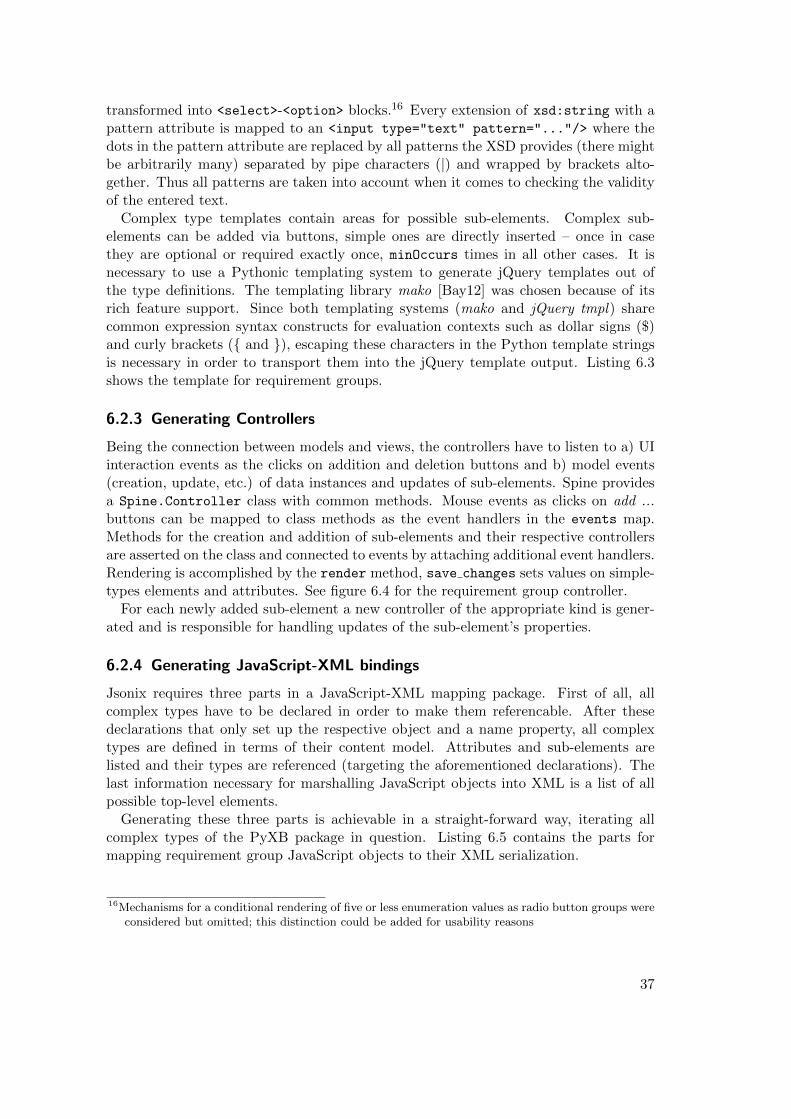
transformed into <select>-<option> blocks.16 Every extension of xsd:string with apattern attribute is mapped to an <input type="text" pattern="..."/> where thedots in the pattern attribute are replaced by all patterns the XSD provides (there mightbe arbitrarily many) separated by pipe characters (|) and wrapped by brackets alto-gether. Thus all patterns are taken into account when it comes to checking the validityof the entered text.
Complex type templates contain areas for possible sub-elements. Complex sub-elements can be added via buttons, simple ones are directly inserted – once in casethey are optional or required exactly once, minOccurs times in all other cases. It isnecessary to use a Pythonic templating system to generate jQuery templates out ofthe type definitions. The templating library mako [Bay12] was chosen because of itsrich feature support. Since both templating systems (mako and jQuery tmpl) sharecommon expression syntax constructs for evaluation contexts such as dollar signs ($)and curly brackets ({ and }), escaping these characters in the Python template stringsis necessary in order to transport them into the jQuery template output. Listing 6.3shows the template for requirement groups.
6.2.3 Generating Controllers
Being the connection between models and views, the controllers have to listen to a) UIinteraction events as the clicks on addition and deletion buttons and b) model events(creation, update, etc.) of data instances and updates of sub-elements. Spine providesa Spine.Controller class with common methods. Mouse events as clicks on add ...buttons can be mapped to class methods as the event handlers in the events map.Methods for the creation and addition of sub-elements and their respective controllersare asserted on the class and connected to events by attaching additional event handlers.Rendering is accomplished by the render method, save changes sets values on simple-types elements and attributes. See figure 6.4 for the requirement group controller.
For each newly added sub-element a new controller of the appropriate kind is gener-ated and is responsible for handling updates of the sub-element’s properties.
6.2.4 Generating JavaScript-XML bindings
Jsonix requires three parts in a JavaScript-XML mapping package. First of all, allcomplex types have to be declared in order to make them referencable. After thesedeclarations that only set up the respective object and a name property, all complextypes are defined in terms of their content model. Attributes and sub-elements arelisted and their types are referenced (targeting the aforementioned declarations). Thelast information necessary for marshalling JavaScript objects into XML is a list of allpossible top-level elements.
Generating these three parts is achievable in a straight-forward way, iterating allcomplex types of the PyXB package in question. Listing 6.5 contains the parts formapping requirement group JavaScript objects to their XML serialization.
16Mechanisms for a conditional rendering of five or less enumeration values as radio button groups wereconsidered but omitted; this distinction could be added for usability reasons
37
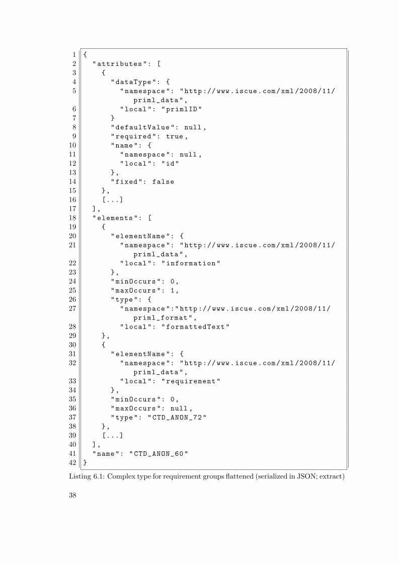
1 {
2 "attributes ": [
3 {
4 "dataType ": {
5 "namespace ": "http ://www.iscue.com/xml /2008/11/
priml_data",
6 "local ": "primlID"
7 }
8 "defaultValue ": null ,
9 "required ": true ,
10 "name": {
11 "namespace ": null ,
12 "local ": "id"
13 },
14 "fixed ": false
15 },
16 [...]
17 ],
18 "elements ": [
19 {
20 "elementName ": {
21 "namespace ": "http ://www.iscue.com/xml /2008/11/
priml_data",
22 "local ": "information"
23 },
24 "minOccurs ": 0,
25 "maxOccurs ": 1,
26 "type": {
27 "namespace ":" http ://www.iscue.com/xml /2008/11/
priml_format",
28 "local ": "formattedText"
29 },
30 {
31 "elementName ": {
32 "namespace ": "http ://www.iscue.com/xml /2008/11/
priml_data",
33 "local ": "requirement"
34 },
35 "minOccurs ": 0,
36 "maxOccurs ": null ,
37 "type": "CTD_ANON_72"
38 },
39 [...]
40 ],
41 "name": "CTD_ANON_60"
42 }
Listing 6.1: Complex type for requirement groups flattened (serialized in JSON; extract)
38
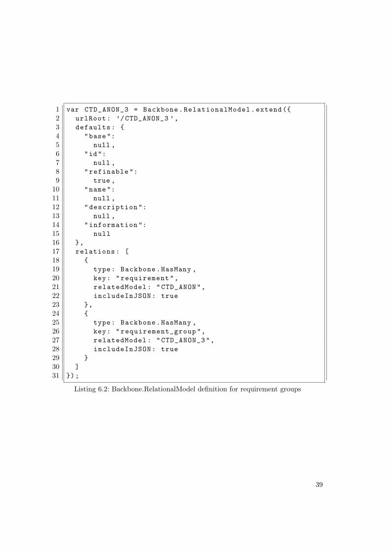
1 var CTD_ANON_3 = Backbone.RelationalModel.extend ({
2 urlRoot: ’/CTD_ANON_3 ’,
3 defaults: {
4 "base":
5 null ,
6 "id":
7 null ,
8 "refinable ":
9 true ,
10 "name":
11 null ,
12 "description ":
13 null ,
14 "information ":
15 null
16 },
17 relations: [
18 {
19 type: Backbone.HasMany ,
20 key: "requirement",
21 relatedModel: "CTD_ANON",
22 includeInJSON: true
23 },
24 {
25 type: Backbone.HasMany ,
26 key: "requirement_group",
27 relatedModel: "CTD_ANON_3",
28 includeInJSON: true
29 }
30 ]
31 });
Listing 6.2: Backbone.RelationalModel definition for requirement groups
39
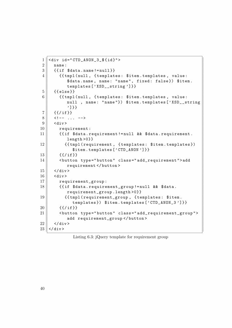
1 <div id=" CTD_ANON_3_${id}">
2 name:
3 {{if $data.name!=null}}
4 {{tmpl(null , {templates: $item.templates , value:
$data.name , name: "name", fixed: false }) $item.
templates[’XSD__string ’]}}
5 {{else}}
6 {{tmpl(null , {templates: $item.templates , value:
null , name: "name "}) $item.templates[’XSD__string
’]}}
7 {{/if}}
8 <!-- ... -->
9 <div >
10 requirement:
11 {{if $data.requirement !=null && $data.requirement.
length >0}}
12 {{tmpl(requirement , {templates: $item.templates })
$item.templates[’CTD_ANON ’]}}
13 {{/if}}
14 <button type=" button" class=" add_requirement">add
requirement </button >
15 </div >
16 <div >
17 requirement_group:
18 {{if $data.requirement_group !=null && $data.
requirement_group.length >0}}
19 {{tmpl(requirement_group , {templates: $item.
templates }) $item.templates[’CTD_ANON_3 ’]}}
20 {{/if}}
21 <button type=" button" class=" add_requirement_group">
add requirement_group </button >
22 </div >
23 </div >
Listing 6.3: jQuery template for requirement group
40
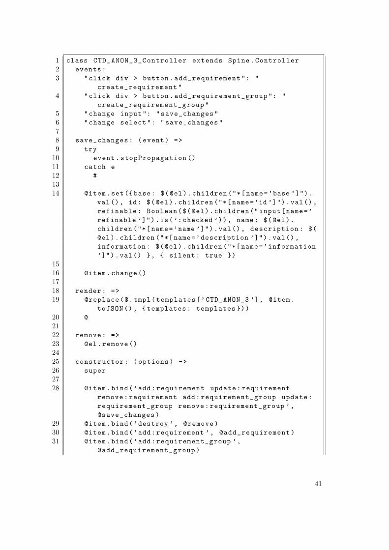
1 class CTD_ANON_3_Controller extends Spine.Controller
2 events:
3 "click div > button.add_requirement ": "
create_requirement"
4 "click div > button.add_requirement_group ": "
create_requirement_group"
5 "change input ": "save_changes"
6 "change select ": "save_changes"
78 save_changes: (event) =>
9 try
10 event.stopPropagation ()
11 catch e
12 #
1314 @item.set({base: $(@el).children ("*[ name=’base ’]").
val(), id: $(@el).children ("*[ name=’id ’]").val(),
refinable: Boolean($(@el).children ("input[name=’
refinable ’]").is(’:checked ’)), name: $(@el).
children ("*[ name=’name ’]").val(), description: $(
@el).children ("*[ name=’description ’]").val(),
information: $(@el).children ("*[ name=’information
’]").val() }, { silent: true })
1516 @item.change ()
1718 render: =>
19 @replace($.tmpl(templates[’CTD_ANON_3 ’], @item.
toJSON (), {templates: templates }))
20 @
2122 remove: =>
23 @el.remove ()
2425 constructor: (options) ->
26 super
2728 @item.bind(’add:requirement update:requirement
remove:requirement add:requirement_group update:
requirement_group remove:requirement_group ’,
@save_changes)
29 @item.bind(’destroy ’, @remove)
30 @item.bind(’add:requirement ’, @add_requirement)
31 @item.bind(’add:requirement_group ’,
@add_requirement_group)
41
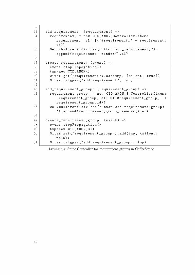
3233 add_requirement: (requirement) =>
34 requirement_ = new CTD_ANON_Controller(item:
requirement , el: $(’#requirement_ ’ + requirement.
id))
35 @el.children(’div:has(button.add_requirement)’).
append(requirement_.render ().el)
3637 create_requirement: (event) =>
38 event.stopPropagation ()
39 tmp=new CTD_ANON ()
40 @item.get(’requirement ’).add(tmp , {silent: true})
41 @item.trigger(’add:requirement ’, tmp)
4243 add_requirement_group: (requirement_group) =>
44 requirement_group_ = new CTD_ANON_3_Controller(item:
requirement_group , el: $(’# requirement_group_ ’ +
requirement_group.id))
45 @el.children(’div:has(button.add_requirement_group)
’).append(requirement_group_.render ().el)
4647 create_requirement_group: (event) =>
48 event.stopPropagation ()
49 tmp=new CTD_ANON_3 ()
50 @item.get(’requirement_group ’).add(tmp , {silent:
true})
51 @item.trigger(’add:requirement_group ’, tmp)
Listing 6.4: Spine.Controller for requirement groups in CoffeeScript
42
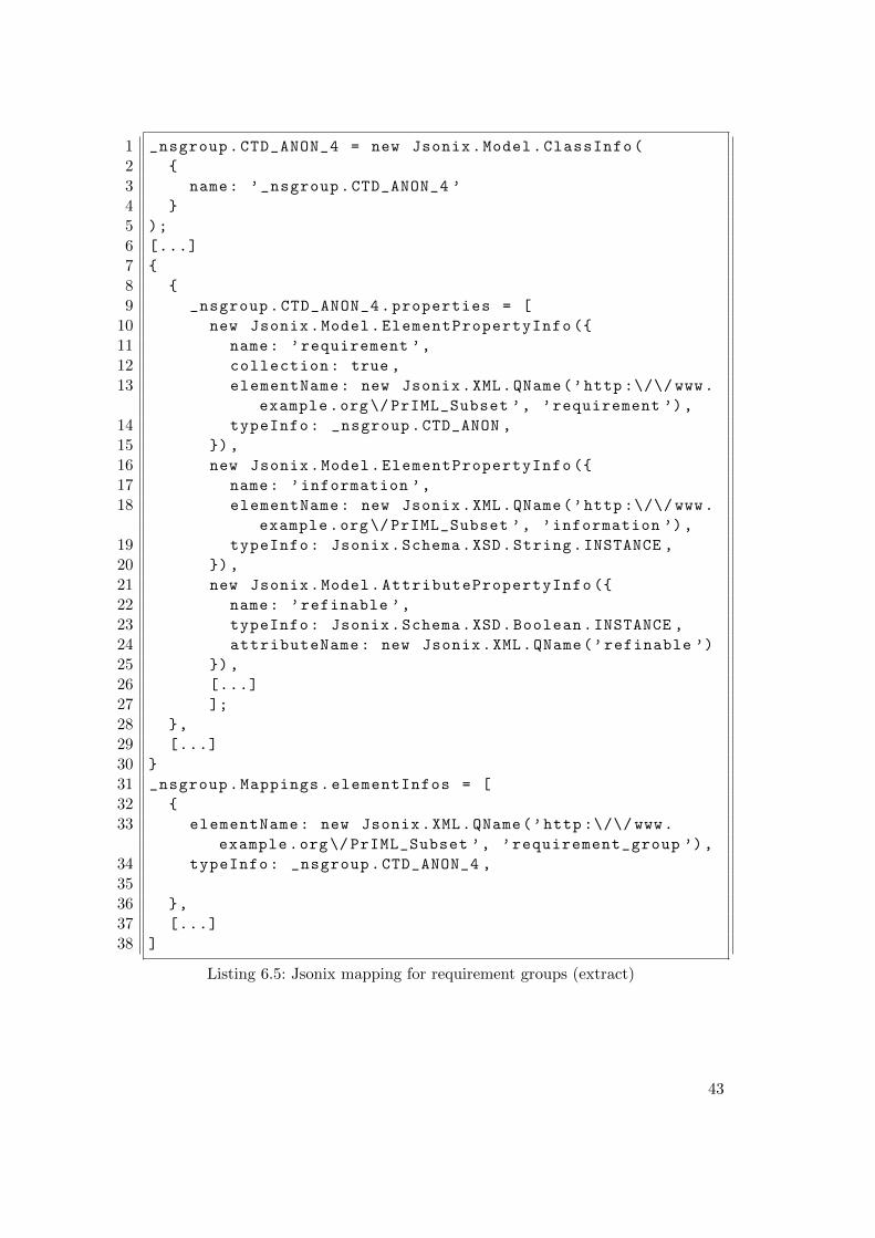
1 _nsgroup.CTD_ANON_4 = new Jsonix.Model.ClassInfo(
2 {
3 name: ’_nsgroup.CTD_ANON_4 ’
4 }
5 );
6 [...]
7 {
8 {
9 _nsgroup.CTD_ANON_4.properties = [
10 new Jsonix.Model.ElementPropertyInfo ({
11 name: ’requirement ’,
12 collection: true ,
13 elementName: new Jsonix.XML.QName(’http :\/\/ www.
example.org\/ PrIML_Subset ’, ’requirement ’),
14 typeInfo: _nsgroup.CTD_ANON ,
15 }),
16 new Jsonix.Model.ElementPropertyInfo ({
17 name: ’information ’,
18 elementName: new Jsonix.XML.QName(’http :\/\/ www.
example.org\/ PrIML_Subset ’, ’information ’),
19 typeInfo: Jsonix.Schema.XSD.String.INSTANCE ,
20 }),
21 new Jsonix.Model.AttributePropertyInfo ({
22 name: ’refinable ’,
23 typeInfo: Jsonix.Schema.XSD.Boolean.INSTANCE ,
24 attributeName: new Jsonix.XML.QName(’refinable ’)
25 }),
26 [...]
27 ];
28 },
29 [...]
30 }
31 _nsgroup.Mappings.elementInfos = [
32 {
33 elementName: new Jsonix.XML.QName(’http :\/\/ www.
example.org\/ PrIML_Subset ’, ’requirement_group ’),
34 typeInfo: _nsgroup.CTD_ANON_4 ,
3536 },
37 [...]
38 ]
Listing 6.5: Jsonix mapping for requirement groups (extract)
43
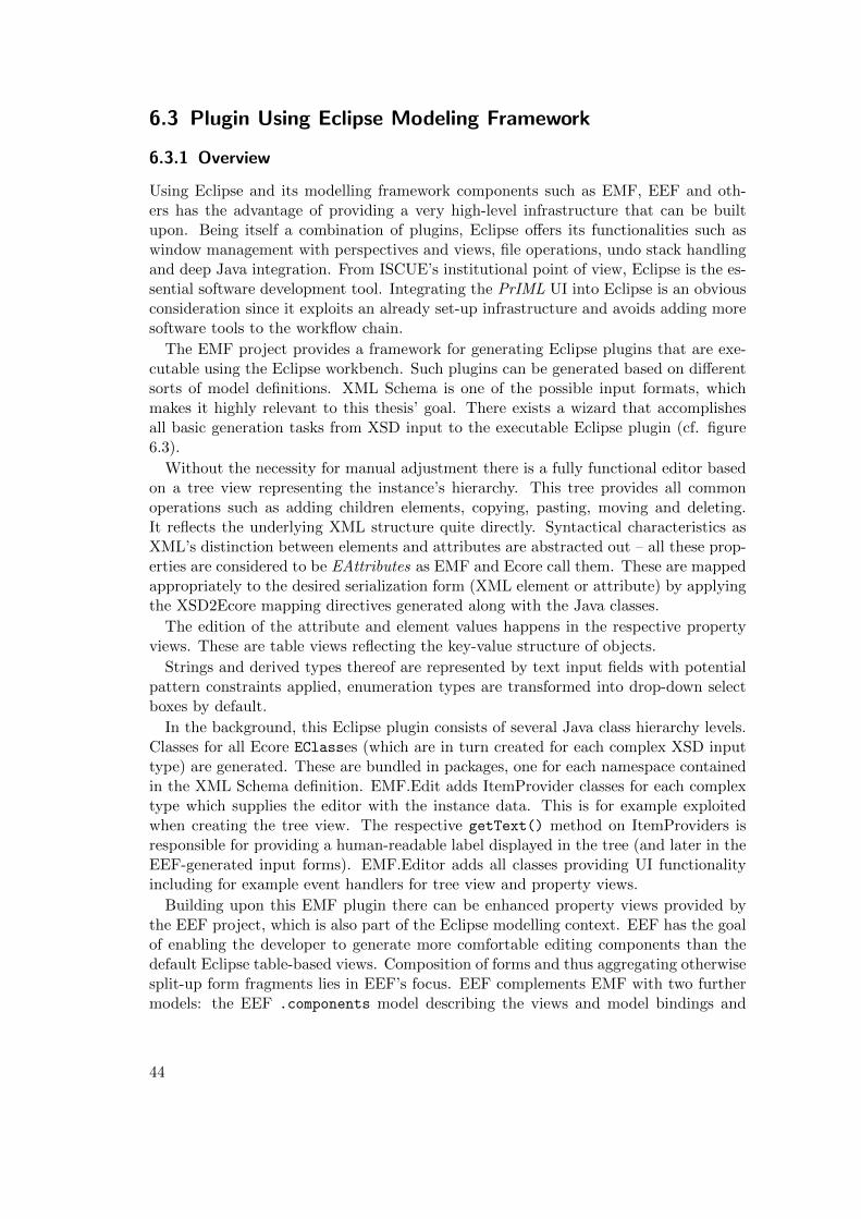
6.3 Plugin Using Eclipse Modeling Framework
6.3.1 Overview
Using Eclipse and its modelling framework components such as EMF, EEF and oth-ers has the advantage of providing a very high-level infrastructure that can be builtupon. Being itself a combination of plugins, Eclipse offers its functionalities such aswindow management with perspectives and views, file operations, undo stack handlingand deep Java integration. From ISCUE’s institutional point of view, Eclipse is the es-sential software development tool. Integrating the PrIML UI into Eclipse is an obviousconsideration since it exploits an already set-up infrastructure and avoids adding moresoftware tools to the workflow chain.
The EMF project provides a framework for generating Eclipse plugins that are exe-cutable using the Eclipse workbench. Such plugins can be generated based on differentsorts of model definitions. XML Schema is one of the possible input formats, whichmakes it highly relevant to this thesis’ goal. There exists a wizard that accomplishesall basic generation tasks from XSD input to the executable Eclipse plugin (cf. figure6.3).
Without the necessity for manual adjustment there is a fully functional editor basedon a tree view representing the instance’s hierarchy. This tree provides all commonoperations such as adding children elements, copying, pasting, moving and deleting.It reflects the underlying XML structure quite directly. Syntactical characteristics asXML’s distinction between elements and attributes are abstracted out – all these prop-erties are considered to be EAttributes as EMF and Ecore call them. These are mappedappropriately to the desired serialization form (XML element or attribute) by applyingthe XSD2Ecore mapping directives generated along with the Java classes.
The edition of the attribute and element values happens in the respective propertyviews. These are table views reflecting the key-value structure of objects.
Strings and derived types thereof are represented by text input fields with potentialpattern constraints applied, enumeration types are transformed into drop-down selectboxes by default.
In the background, this Eclipse plugin consists of several Java class hierarchy levels.Classes for all Ecore EClasses (which are in turn created for each complex XSD inputtype) are generated. These are bundled in packages, one for each namespace containedin the XML Schema definition. EMF.Edit adds ItemProvider classes for each complextype which supplies the editor with the instance data. This is for example exploitedwhen creating the tree view. The respective getText() method on ItemProviders isresponsible for providing a human-readable label displayed in the tree (and later in theEEF-generated input forms). EMF.Editor adds all classes providing UI functionalityincluding for example event handlers for tree view and property views.
Building upon this EMF plugin there can be enhanced property views provided bythe EEF project, which is also part of the Eclipse modelling context. EEF has the goalof enabling the developer to generate more comfortable editing components than thedefault Eclipse table-based views. Composition of forms and thus aggregating otherwisesplit-up form fragments lies in EEF’s focus. EEF complements EMF with two furthermodels: the EEF .components model describing the views and model bindings and
44
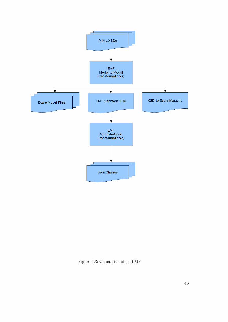
Figure 6.3: Generation steps EMF
45
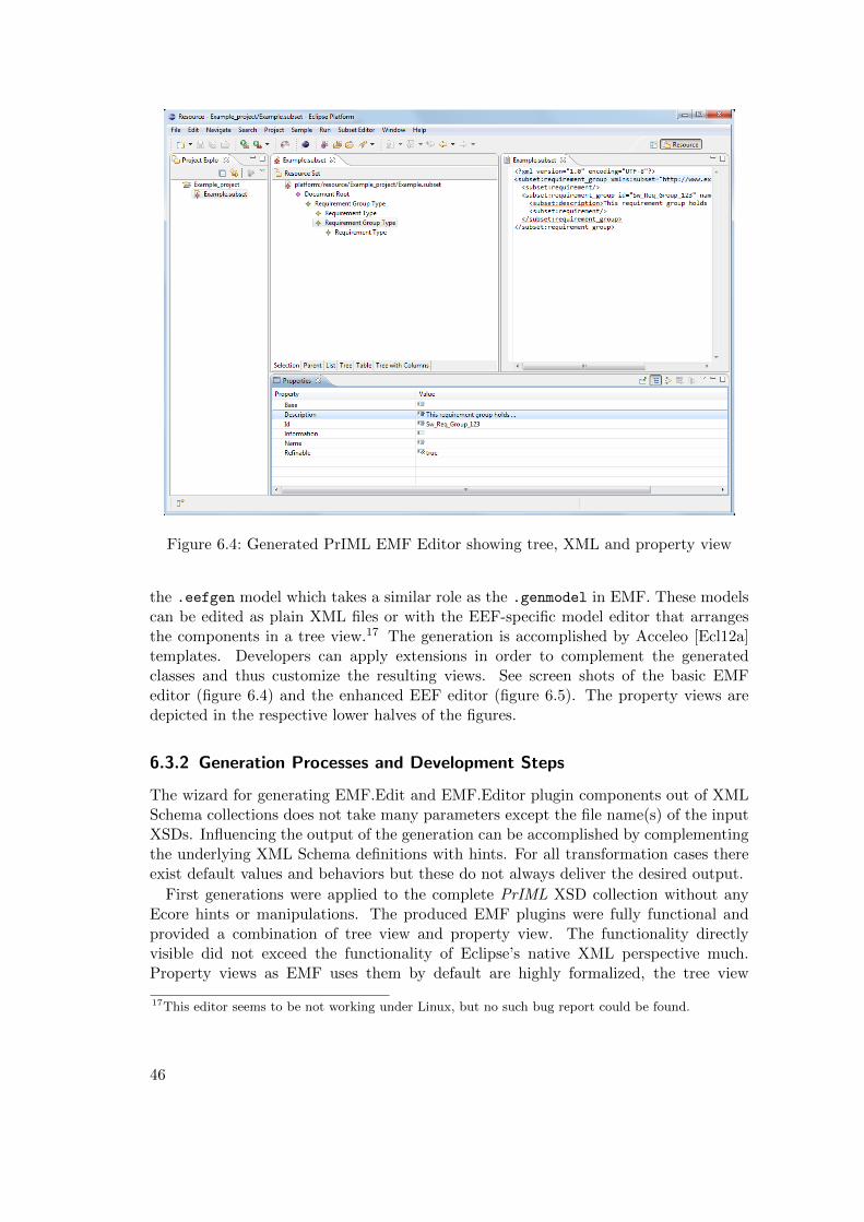
Figure 6.4: Generated PrIML EMF Editor showing tree, XML and property view
the .eefgen model which takes a similar role as the .genmodel in EMF. These modelscan be edited as plain XML files or with the EEF-specific model editor that arrangesthe components in a tree view.17 The generation is accomplished by Acceleo [Ecl12a]templates. Developers can apply extensions in order to complement the generatedclasses and thus customize the resulting views. See screen shots of the basic EMFeditor (figure 6.4) and the enhanced EEF editor (figure 6.5). The property views aredepicted in the respective lower halves of the figures.
6.3.2 Generation Processes and Development Steps
The wizard for generating EMF.Edit and EMF.Editor plugin components out of XMLSchema collections does not take many parameters except the file name(s) of the inputXSDs. Influencing the output of the generation can be accomplished by complementingthe underlying XML Schema definitions with hints. For all transformation cases thereexist default values and behaviors but these do not always deliver the desired output.
First generations were applied to the complete PrIML XSD collection without anyEcore hints or manipulations. The produced EMF plugins were fully functional andprovided a combination of tree view and property view. The functionality directlyvisible did not exceed the functionality of Eclipse’s native XML perspective much.Property views as EMF uses them by default are highly formalized, the tree view
17This editor seems to be not working under Linux, but no such bug report could be found.
46
Figure 6.5: Generated PrIML EEF Editor showing tree, XML and property view
reflects the XML tree hierarchy.
In the next step, EEF’s generation processes were applied to EMF’s output. Seefigure 6.6 for an overview of the steps taken and for detailed textual descriptions of allthese generation steps cf. appendix A.2. As with the basic EMF generations, the EEFprocesses were tried unparametrized. The result after applying the steps described inEEF’s user guide [Ecl12b] was a partially working, enhanced version of the EMF.Editorplugin. The property views did not consistently behave as expected, for some elementsthe properties were not represented by form widgets. In these cases there was one textinput field and eventual child elements were expanded in textual form into this input.Any property views for elements further down the hierarchy could not be displayed,instead the Eclipse default error message “Properties not available.” was displayed.
In order to resolve this behavior the approach was to isolate a distinct subset of thePrIML vocabulary. The subset was chosen with respect to having one or more seem-ingly misbehaving element structures. Reducing the amount of involved elements im-proved generation performance during the often repeated steps and the maintainabilityin general. Based on the requirement group element which bundles the descriptionsand relations of associated system or software requirements the subset was formed.All referenced types and elements were collected and persisted into one separate XMLSchema file. Two simplifications were applied for this test subset: the occurrences of themixed type format:formattedText18 were replaced by xsd:string and the xml:base
18This type allows for combinations of text content and markup elements.
47
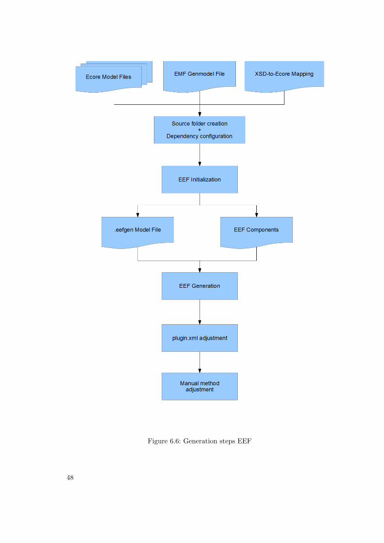
Figure 6.6: Generation steps EEF
48
attribute was omitted.
Analyzing this smaller subset of seven global element declarations, nine complextype definitions (including types extending/ restricting each other) and two simpletype definitions led to the insight that repeatable XML Schema model groups (i.e.,xsd:sequences and xsd:choices) were correctly handled by EMF, but EEF seemedto incorrectly transform these into widgets. EMF uses a mechanism called FeatureMapfor such model groups with a maxOccurs attribute value greater than 1. This causesthe element containing the respective repeatable model group to get an extra group
property in the Ecore model representation. EEF’s generation step interprets this asa property to be converted into a widget and does not take the components withinthe group (i.e., element declarations) into account. Adding hints in the input XSD fileprevents EMF from creating FeatureMaps for repeatable XSD model groups in the firstplace and thus provided proper input for EEF’s generation.
Based on this the EEF generation was applied again and the result was discussedwith ISCUE’s management and staff responsible for PrIML. In addition to the generalrequirements for a PrIML UI the following aspects were brought into focus specificallyfor the Eclipse case:
• behavior of manually applied code changes when re-generations are applied,• behavior and possible functional limitations of property views and tree views in
Eclipse’s workbench,• introduction of a Rich Text editor for mixed types
(especially format:formattedText),• changing the textual labels of elements in tree and table view,• representing sub-tables with more than one column for detailed view,• possibilities to enable widget’s resizability (not enabled by default),• directly creating mandatory sub-elements,• methods for integrating more than one XML element level on one form and hence
deliberate limitations of the tree view depth,• possibilities of reflecting file management (i.e., modularization) in the UI.
The ideas behind these aspects and their possibilities of implementation are describedbelow.
6.3.3 Customization Steps
After completing EEF’s generation and the gathering of exemplary adjustment neces-sities (see list above) the processes of implementing and possible problems encounteredduring these attempts are described in this chapter.
Code protection when re-generating The fact that EMF uses protected source codezones marked by JavaDoc @generated NOT tags, leads to the issue of the behavior of thegeneration processes when encountering methods, that have to be overwritten, but aremarked as protected. A case where this comes into focus, is, when the order of widgetson a form is adjusted by changing the order of addStep method invocations. Changingthe underlying model (be it the XSD or the Ecore model) leads to a mandatory re-generation of the *EditionPartForm Java classes in order to appropriately reflect all
49
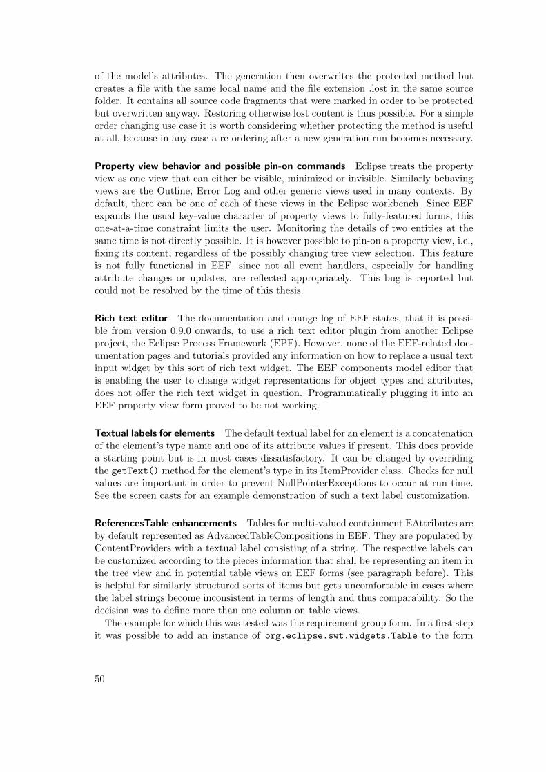
of the model’s attributes. The generation then overwrites the protected method butcreates a file with the same local name and the file extension .lost in the same sourcefolder. It contains all source code fragments that were marked in order to be protectedbut overwritten anyway. Restoring otherwise lost content is thus possible. For a simpleorder changing use case it is worth considering whether protecting the method is usefulat all, because in any case a re-ordering after a new generation run becomes necessary.
Property view behavior and possible pin-on commands Eclipse treats the propertyview as one view that can either be visible, minimized or invisible. Similarly behavingviews are the Outline, Error Log and other generic views used in many contexts. Bydefault, there can be one of each of these views in the Eclipse workbench. Since EEFexpands the usual key-value character of property views to fully-featured forms, thisone-at-a-time constraint limits the user. Monitoring the details of two entities at thesame time is not directly possible. It is however possible to pin-on a property view, i.e.,fixing its content, regardless of the possibly changing tree view selection. This featureis not fully functional in EEF, since not all event handlers, especially for handlingattribute changes or updates, are reflected appropriately. This bug is reported butcould not be resolved by the time of this thesis.
Rich text editor The documentation and change log of EEF states, that it is possi-ble from version 0.9.0 onwards, to use a rich text editor plugin from another Eclipseproject, the Eclipse Process Framework (EPF). However, none of the EEF-related doc-umentation pages and tutorials provided any information on how to replace a usual textinput widget by this sort of rich text widget. The EEF components model editor thatis enabling the user to change widget representations for object types and attributes,does not offer the rich text widget in question. Programmatically plugging it into anEEF property view form proved to be not working.
Textual labels for elements The default textual label for an element is a concatenationof the element’s type name and one of its attribute values if present. This does providea starting point but is in most cases dissatisfactory. It can be changed by overridingthe getText() method for the element’s type in its ItemProvider class. Checks for nullvalues are important in order to prevent NullPointerExceptions to occur at run time.See the screen casts for an example demonstration of such a text label customization.
ReferencesTable enhancements Tables for multi-valued containment EAttributes areby default represented as AdvancedTableCompositions in EEF. They are populated byContentProviders with a textual label consisting of a string. The respective labels canbe customized according to the pieces information that shall be representing an item inthe tree view and in potential table views on EEF forms (see paragraph before). Thisis helpful for similarly structured sorts of items but gets uncomfortable in cases wherethe label strings become inconsistent in terms of length and thus comparability. So thedecision was to define more than one column on table views.
The example for which this was tested was the requirement group form. In a first stepit was possible to add an instance of org.eclipse.swt.widgets.Table to the form
50
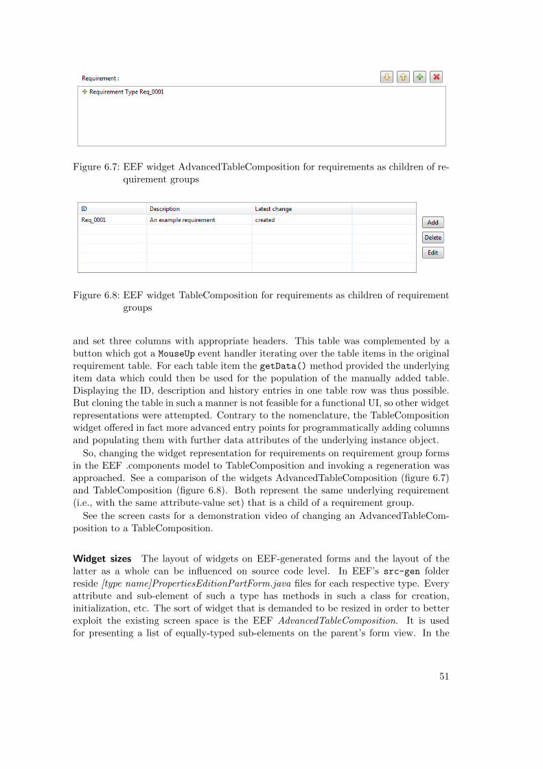
Figure 6.7: EEF widget AdvancedTableComposition for requirements as children of re-quirement groups
Figure 6.8: EEF widget TableComposition for requirements as children of requirementgroups
and set three columns with appropriate headers. This table was complemented by abutton which got a MouseUp event handler iterating over the table items in the originalrequirement table. For each table item the getData() method provided the underlyingitem data which could then be used for the population of the manually added table.Displaying the ID, description and history entries in one table row was thus possible.But cloning the table in such a manner is not feasible for a functional UI, so other widgetrepresentations were attempted. Contrary to the nomenclature, the TableCompositionwidget offered in fact more advanced entry points for programmatically adding columnsand populating them with further data attributes of the underlying instance object.
So, changing the widget representation for requirements on requirement group formsin the EEF .components model to TableComposition and invoking a regeneration wasapproached. See a comparison of the widgets AdvancedTableComposition (figure 6.7)and TableComposition (figure 6.8). Both represent the same underlying requirement(i.e., with the same attribute-value set) that is a child of a requirement group.
See the screen casts for a demonstration video of changing an AdvancedTableCom-position to a TableComposition.
Widget sizes The layout of widgets on EEF-generated forms and the layout of thelatter as a whole can be influenced on source code level. In EEF’s src-gen folderreside [type name]PropertiesEditionPartForm.java files for each respective type. Everyattribute and sub-element of such a type has methods in such a class for creation,initialization, etc. The sort of widget that is demanded to be resized in order to betterexploit the existing screen space is the EEF AdvancedTableComposition. It is usedfor presenting a list of equally-typed sub-elements on the parent’s form view. In the
51
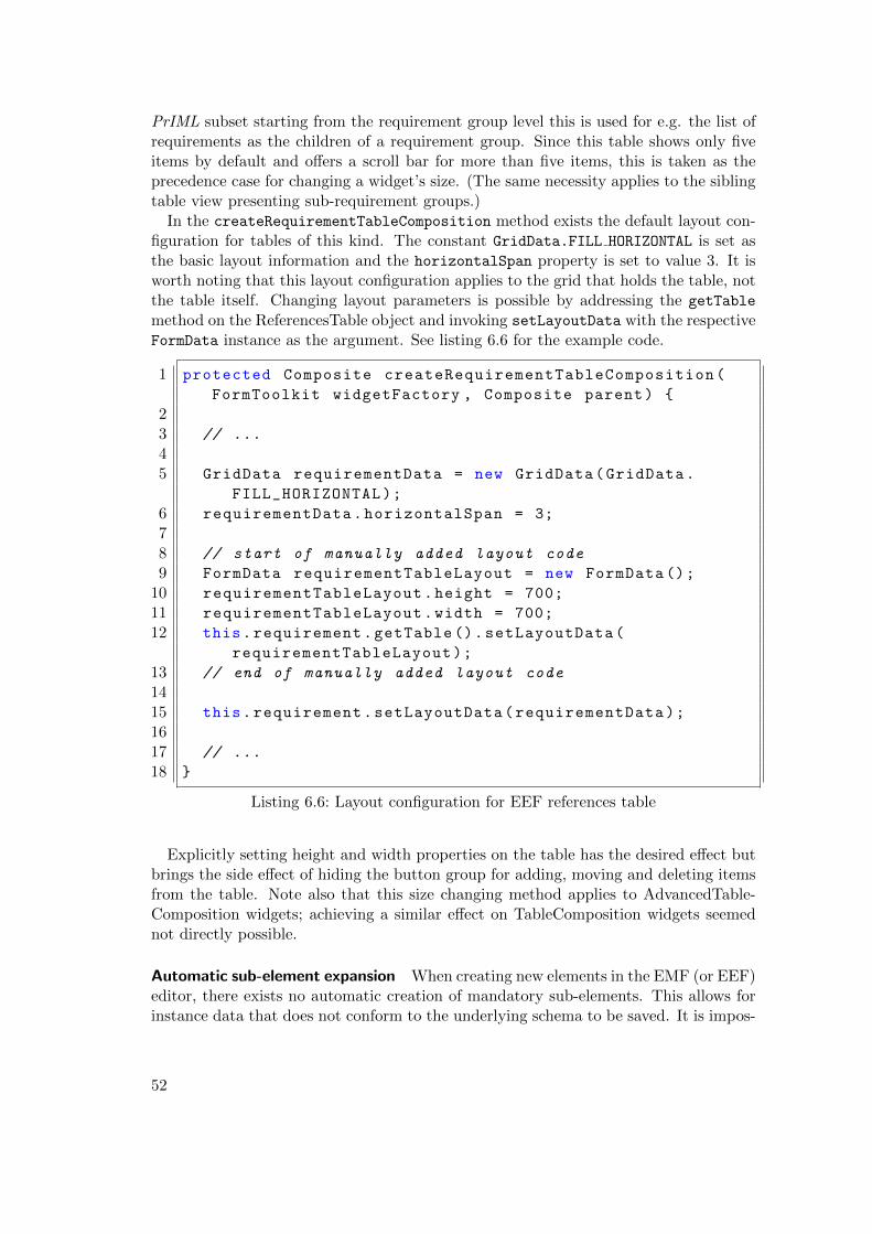
PrIML subset starting from the requirement group level this is used for e.g. the list ofrequirements as the children of a requirement group. Since this table shows only fiveitems by default and offers a scroll bar for more than five items, this is taken as theprecedence case for changing a widget’s size. (The same necessity applies to the siblingtable view presenting sub-requirement groups.)
In the createRequirementTableComposition method exists the default layout con-figuration for tables of this kind. The constant GridData.FILL HORIZONTAL is set asthe basic layout information and the horizontalSpan property is set to value 3. It isworth noting that this layout configuration applies to the grid that holds the table, notthe table itself. Changing layout parameters is possible by addressing the getTable
method on the ReferencesTable object and invoking setLayoutData with the respectiveFormData instance as the argument. See listing 6.6 for the example code.
1 protected Composite createRequirementTableComposition(
FormToolkit widgetFactory , Composite parent) {
23 // ...
45 GridData requirementData = new GridData(GridData.
FILL_HORIZONTAL);
6 requirementData.horizontalSpan = 3;
78 // start of manually added layout code
9 FormData requirementTableLayout = new FormData ();
10 requirementTableLayout.height = 700;
11 requirementTableLayout.width = 700;
12 this.requirement.getTable ().setLayoutData(
requirementTableLayout);
13 // end of manually added layout code
1415 this.requirement.setLayoutData(requirementData);
1617 // ...
18 }
Listing 6.6: Layout configuration for EEF references table
Explicitly setting height and width properties on the table has the desired effect butbrings the side effect of hiding the button group for adding, moving and deleting itemsfrom the table. Note also that this size changing method applies to AdvancedTable-Composition widgets; achieving a similar effect on TableComposition widgets seemednot directly possible.
Automatic sub-element expansion When creating new elements in the EMF (or EEF)editor, there exists no automatic creation of mandatory sub-elements. This allows forinstance data that does not conform to the underlying schema to be saved. It is impos-
52
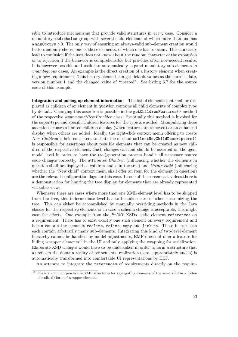
sible to introduce mechanisms that provide valid structures in every case. Consider amandatory xsd:choice group with several child elements of which more than one hasa minOccurs >0. The only way of ensuring an always-valid sub-element creation wouldbe to randomly choose one of those elements, of which one has to occur. This can easilylead to confusion if the user does not know about the random character of the expansionor to rejection if the behavior is comprehensible but provides often not-needed results.It is however possible and useful to automatically expand mandatory sub-elements inunambiguous cases. An example is the direct creation of a history element when creat-ing a new requirement. This history element can get default values as the current date,version number 1 and the changed value of “created”. See listing 6.7 for the sourcecode of this example.
Integration and pulling up element information The list of elements that shall be dis-played as children of an element in question contains all child elements of complex typeby default. Changing this assertion is possible in the getChildrenFeatures() methodof the respective [type name]ItemProvider class. Eventually this method is invoked forthe super-type and specific children features for the type are added. Manipulating theseassertions causes a limited children display (when features are removed) or an enhanceddisplay when others are added. Ideally, the right-click context menu offering to createNew Children is held consistent to that: the method collectNewChildDescriptors()
is responsible for assertions about possible elements that can be created as new chil-dren of the respective element. Such changes can and should be asserted on the .gen-model level in order to have the (re-)generation process handle all necessary sourcecode changes correctly. The attributes Children (influencing whether the elements inquestion shall be displayed as children nodes in the tree) and Create child (influencingwhether the “New child” context menu shall offer an item for the element in question)are the relevant configuration flags for this case. In one of the screen cast videos there isa demonstration for limiting the tree display for elements that are already representedvia table views.
Whenever there are cases where more than one XML element level has to be skippedfrom the tree, this indermediate level has to be taken care of when customizing thetree. This can either be accomplished by manually overriding methods in the Javaclasses for the respective elements or in case a schema change is acceptable, this mightease the efforts. One example from the PrIML XSDs is the element references ona requirement. There has to exist exactly one such element on every requirement andit can contain the elements realize, refine, copy and link to. These in turn caneach contain arbitrarily many sub-elements. Integrating this kind of two-level elementhierarchy cannot be handled by model adjustments, EMF does not offer a feature forhiding wrapper elements19 in the UI and only applying the wrapping for serialization.Elaborate XSD changes would have to be undertaken in order to form a structure thata) reflects the domain reality of refinements, realizations, etc. appropriately and b) isautomatically transformed into comfortable UI representations by EEF.
An attempt to integrate the references of requirements directly on the require-
19This is a common practice in XML structures for aggregating elements of the same kind in a (oftenpluralized) form of wrapper element.
53
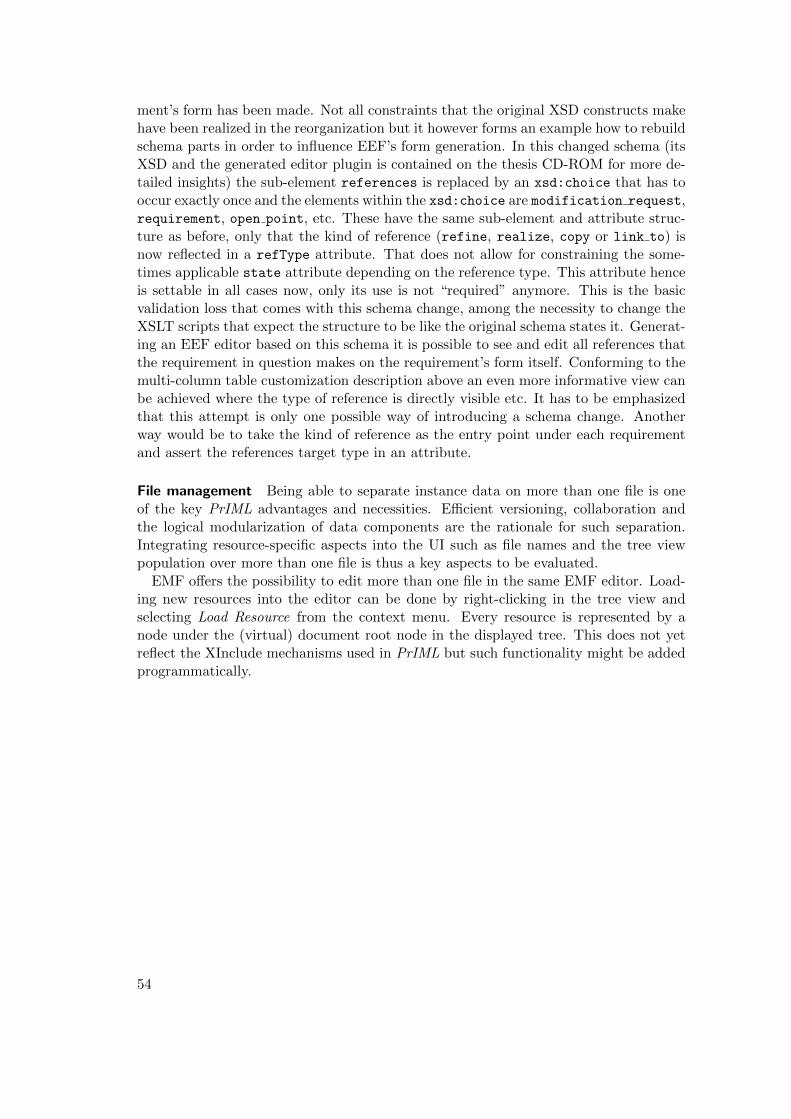
ment’s form has been made. Not all constraints that the original XSD constructs makehave been realized in the reorganization but it however forms an example how to rebuildschema parts in order to influence EEF’s form generation. In this changed schema (itsXSD and the generated editor plugin is contained on the thesis CD-ROM for more de-tailed insights) the sub-element references is replaced by an xsd:choice that has tooccur exactly once and the elements within the xsd:choice are modification request,requirement, open point, etc. These have the same sub-element and attribute struc-ture as before, only that the kind of reference (refine, realize, copy or link to) isnow reflected in a refType attribute. That does not allow for constraining the some-times applicable state attribute depending on the reference type. This attribute henceis settable in all cases now, only its use is not “required” anymore. This is the basicvalidation loss that comes with this schema change, among the necessity to change theXSLT scripts that expect the structure to be like the original schema states it. Generat-ing an EEF editor based on this schema it is possible to see and edit all references thatthe requirement in question makes on the requirement’s form itself. Conforming to themulti-column table customization description above an even more informative view canbe achieved where the type of reference is directly visible etc. It has to be emphasizedthat this attempt is only one possible way of introducing a schema change. Anotherway would be to take the kind of reference as the entry point under each requirementand assert the references target type in an attribute.
File management Being able to separate instance data on more than one file is oneof the key PrIML advantages and necessities. Efficient versioning, collaboration andthe logical modularization of data components are the rationale for such separation.Integrating resource-specific aspects into the UI such as file names and the tree viewpopulation over more than one file is thus a key aspects to be evaluated.
EMF offers the possibility to edit more than one file in the same EMF editor. Load-ing new resources into the editor can be done by right-clicking in the tree view andselecting Load Resource from the context menu. Every resource is represented by anode under the (virtual) document root node in the displayed tree. This does not yetreflect the XInclude mechanisms used in PrIML but such functionality might be addedprogrammatically.
54
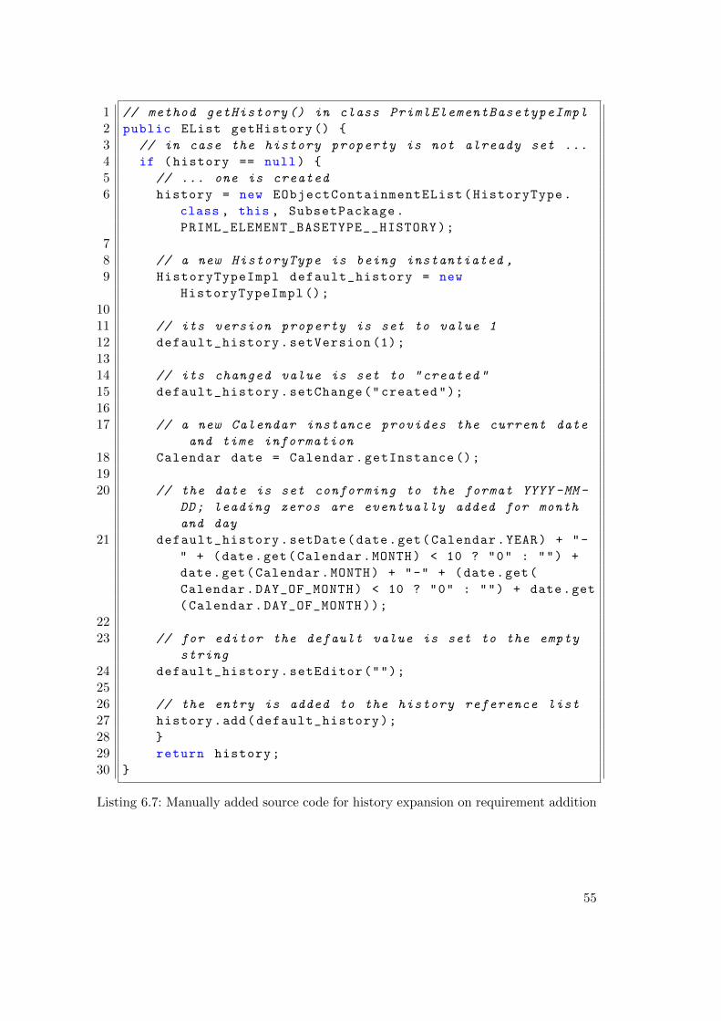
1 // method getHistory () in class PrimlElementBasetypeImpl
2 public EList getHistory () {
3 // in case the history property is not already set ...
4 if (history == null) {
5 // ... one is created
6 history = new EObjectContainmentEList(HistoryType.
class , this , SubsetPackage.
PRIML_ELEMENT_BASETYPE__HISTORY);
78 // a new HistoryType is being instantiated ,
9 HistoryTypeImpl default_history = new
HistoryTypeImpl ();
1011 // its version property is set to value 1
12 default_history.setVersion (1);
1314 // its changed value is set to "created"
15 default_history.setChange("created");
1617 // a new Calendar instance provides the current date
and time information
18 Calendar date = Calendar.getInstance ();
1920 // the date is set conforming to the format YYYY -MM -
DD; leading zeros are eventually added for month
and day
21 default_history.setDate(date.get(Calendar.YEAR) + "-
" + (date.get(Calendar.MONTH) < 10 ? "0" : "") +
date.get(Calendar.MONTH) + "-" + (date.get(
Calendar.DAY_OF_MONTH) < 10 ? "0" : "") + date.get
(Calendar.DAY_OF_MONTH));
2223 // for editor the default value is set to the empty
string
24 default_history.setEditor("");
2526 // the entry is added to the history reference list
27 history.add(default_history);
28 }
29 return history;
30 }
Listing 6.7: Manually added source code for history expansion on requirement addition
55
6.4 Comparison
After describing and explaining both solutions in the two chapters above, a comparisonis drawn. This is done using the aspects and requirements listed in chaper 6.1 andin a more general manner afterwards. For both protoypes the extent, to which therespective requirement is implemented, is described. This comparison is based on thestate that the prototypes have in the end of the thesis period.
6.4.1 Requirement-Based Evaluations
See table 6.2 for a tabular comparison complementing the textual comparion in thischapter.
“The UI is able to run on Windows, Linux and MacOS X” Both approaches followa platform-independent paradigm. Web applications are dependent on the existence ofa (modern20) web browser. All three operating systems Windows, Linux and MacOS Xsupport such modern web browsers, thus the web application is able to run on all of theseplatforms. Differences between the browsers can occur, since every vendor implementsfeatures slightly different but the functionality for the application developed in thisthesis shall be given.
Eclipse is a Java-based platform and hence can be run on any platform supportinga Java Virtual Machine (VM). All three operating systems offer Java support, so therequirement is met by Eclipse and thus by EMF and EEF as well.
Both solutions meet the requirement of being able to run on the three main operatingsystems for desktop devices. Since web applications can in most cases also be used onmobile devices, this can be considered an extra benefit that was not explicitly demanded.The perpetual evolution of web technology and the lack of reliable cross-browser featuresupport is a disadvantage in terms of web application use. Eclipse as an open-sourceIDE and its projects being under continuous developments as well is also not completelyreliable and does not in all cases offer backwards compatibility.
So both approaches provide a platform-independent basis.
“The UI is generated as completely as possible; manual customizations can beapplied to fit needs more exactly” The extent to which a UI and its processes canbe automatically generated is one aspect of this requirement; the other one is theextensibility.
The web application is (apart from the removal of comments in order to enable thefunctionality) designed for a complete generation. Manual extensions can be appliedbut do not have to.
A similar case is EMF: the generation processes provide a fully-functional editor plu-gin that does not need any manual input. EEF is slightly more demanding when it
20The term of a modern web browser is not clearly definable. All current versions of the three mainbrowsers Mozilla Firefox, Google Chrome and Internet Explorer to some extent can be consideredto be “modern”. Internet Explorer versions <= 7 are commonly perceived as critical browsers interms of feature support.
56
comes to manual steps complementing its generations. Copy-pasting generated frag-ments in the respective destination folders and files and overriding specific Java methodsbelongs to these necessary manual steps.21
When it comes to extensibility, the web application can be further developed withfunctions such as drag&drop and introducing domain knowledge for cases like ID refer-ences of certain element types only. The amount of files, lines of code and abstractionlayers is comprehensible. Both the generation methods and the resulting classes andfiles can be modified quite directly. EMF and EEF build on a far more verbose ar-chitecture than the web application. This leads to a high entry threshold but suppliesthe user with a highly modularized infrastructure, once he understands the componentsinteracting with each other.
Summing up, both prototypes have a high generation potential, EEF lessens it slightlyfor the Eclipse approach. The learn-curve is steep for the EMF/EEF frameworks,their advantages lie in the long-run when such a stable architecture allows for reliablecomponents to apply extensions to. The light-weight web solution allows for a bettermaintainability in the beginning but demands for a more extensive amount of hand-coding features when they become necessary.
“Schema changes are reflected in the UI after a regeneration” This requirementis mostly relevant for the distinction between generation time and run time. In bothapproaches schema changes are not reflected at run time but require a regeneration.
Invoking such a regeneration for the web application is accomplished by executingthe command-line Python script again. EMF has different schema layers that canchange. The input XSD(s) can change, the Ecore model derived from the XSD(s),the .genmodel, the .xsd2ecore and EEF’s two model files. EMF and EEF allow forpartial (re-)generation, i.e., regenerating only the parts that require updates. Thisis comfortable when changes and their consequences are completely comprehensiblebut often even small schema changes have consequences in several classes not directlyvisible from a developer’s point of view. Making general decisions on how to introduceschema and model changes and how to make them explicit for (later) comprehensibilitycan be helpful in order to consistently preserve manual changes. Including generatedsource code into versioning systems is usually not recommended but when generatedand manually written source code intermix, it might become useful.
“Manual customizations are protected from being overwritten by a regeneration”In the Python generation processes producing the web application no such featureas protected zones or merging of source code files is available, so manually appliedchanges are by default overwritten if not saved in other folders or files. EMF and EEFuse protected source code zones and thus manual changes can be preserved from beingoverwritten by new generations. This requirement is thus better met by EMF/EEFthan by the self-developed Python methods.
21These steps are automatable but EEF does not itself provide mechanisms to do so. Ant build scriptsfor supporting EEF’s generations are discussed but not available during the time of research.
57
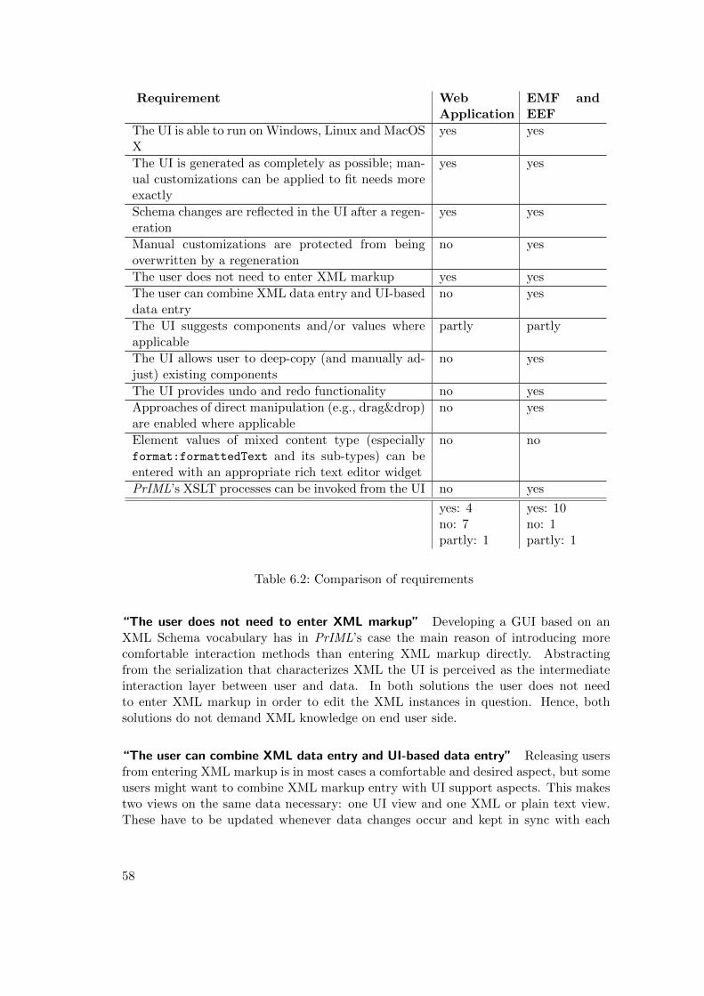
Requirement WebApplication
EMF andEEF
The UI is able to run on Windows, Linux and MacOSX
yes yes
The UI is generated as completely as possible; man-ual customizations can be applied to fit needs moreexactly
yes yes
Schema changes are reflected in the UI after a regen-eration
yes yes
Manual customizations are protected from beingoverwritten by a regeneration
no yes
The user does not need to enter XML markup yes yes
The user can combine XML data entry and UI-baseddata entry
no yes
The UI suggests components and/or values whereapplicable
partly partly
The UI allows user to deep-copy (and manually ad-just) existing components
no yes
The UI provides undo and redo functionality no yes
Approaches of direct manipulation (e.g., drag&drop)are enabled where applicable
no yes
Element values of mixed content type (especiallyformat:formattedText and its sub-types) can beentered with an appropriate rich text editor widget
no no
PrIML’s XSLT processes can be invoked from the UI no yes
yes: 4no: 7partly: 1
yes: 10no: 1partly: 1
Table 6.2: Comparison of requirements
“The user does not need to enter XML markup” Developing a GUI based on anXML Schema vocabulary has in PrIML’s case the main reason of introducing morecomfortable interaction methods than entering XML markup directly. Abstractingfrom the serialization that characterizes XML the UI is perceived as the intermediateinteraction layer between user and data. In both solutions the user does not needto enter XML markup in order to edit the XML instances in question. Hence, bothsolutions do not demand XML knowledge on end user side.
“The user can combine XML data entry and UI-based data entry” Releasing usersfrom entering XML markup is in most cases a comfortable and desired aspect, but someusers might want to combine XML markup entry with UI support aspects. This makestwo views on the same data necessary: one UI view and one XML or plain text view.These have to be updated whenever data changes occur and kept in sync with each
58
other. Eclipse has its concepts of perspectives containing several views. This allows forexactly this kind of manifold editing as just described. Opening an XML instance filewith the generated editor and simultaneously viewing it with an XML view is possible.The Eclipse platform listens to change events and notifies all listeners of data changesin order to give these listeners the chance to update accordingly. The web applicationputs out the XML serialization form of the current elements into a textarea element.This is not automatically updated and changing the content of it does not lead to arespective data update. Enabling it would directly be coupled to the ability to loadexisting instance data into the UI and re-rendering the views. Since this is not possiblein the state of the prototype, the combination of UI data entry and markup edition isonly possible in the EMF plugin solution.
“The UI suggests components and/or values where applicable” Value suggestionsand widgets that only allow for the entry of valid values fall into this category of usersupport. Both EMF and the web application provide such aspects via the choice ofdrop-down menus when encountering enumeration simple types. Choosing one of thesuggested values ensures valid data entry. Automatically setting eventual default orfixed values is another such aspect that is implemented in both solutions. The di-rect expansion of required attributes and sub-elements is a feature that is only partlyimplemented in both solutions. The web application takes minOccurs values into ac-count when rendering sub-elements of elements and pre-fills inputs with default and/orfixed values. EMF does directly fill in default and fixed values but does not pre-renderrequired sub-elements.
Summing up, both approaches implement some potential features, but none of themoffers completely satisfactory mechanisms that exhaust the suggestion potential.
“The UI allows user to deep-copy [...] existing components” When it comes torepetitive data entry where only details in different sub-elements differ, possibilities toeasily copy and adjust existing elements can be helpful. Eclipe’s tree view nativelysupports copying of either single tree nodes or whole tree branches. EMF triggers copyactions when such copying (and deletions analogously) is observed. The web solutiondoes not support direct cloning of elements.
“The UI provides undo and redo functionality” Providing an undo stack that tracksthe last changes applied to the data is a common practice in many kinds of applica-tions. Eclipse as an IDE framework offers undo and redo functionalities by default andplugins in the framework such as the generated editors benefit from them. Browserapplications do not build upon such an infrastructure and have to introduce interactionstacks themselves if demanded. The web prototype in this thesis does not contain anundo stack since it would require complete loading, creating, updating and deletingmechanisms. These are not part of the prototype’s state and thus an undo mechanismis not implemented.
“Approaches of direct manipulation [...] are enabled where applicable” In termsof direct manipulation aspects such as drag&drop the situation is similar to the undo
59
features described above. Applications that exploit an existing infrastructure like theEclipse framework that provide many low-level functions do not need to take care ofthese functions’ implementation. This holds true for dragging and dropping tree nodesin Eclipse as well. Drag&drop is also common in browser applications for some time butis subject to manual development rather than just using anyway existing mechanisms.jQuery UI for example offers library constructs for drag&drop interaction patterns butthis has not been introduced into the web-based approach in this thesis.
“Element values of mixed content type [...] can be entered with an appropriaterich-text editor widget” One of the powerful features in PrIML is the usage of mixedcomplex types for most textual elements. The type format:formattedText and itsderived types allow for the intermixing of text content and sub-elements that mark upthe text. These elements contain constructs for emphasis, tables, links and other struc-turing aspects. Reflecting such mixed-typed elements is by default handled straight-forwardly by both EMF and the web application. The special character of marking upis not reflected since it requires the domain knowledge that wrapping text content inan emph element would ideally lead to typographically emphasizing it. Being able torepresent mixed-typed elements with a rich text editor widget was hence a formulatedrequirement. The EEF documentation does mention a rich text editor widget that canbe included in an EEF property view but attempts to de facto using it in the gener-ated plugin, failed. Neither asserting it in the EEF .components nor programmaticallyadding it to a generated form view could be achieved. Rich text editor plugins existfor web applications, some only usable for HTML markup, some customizable to fitspecific needs. This thesis protoype web application does not introduce such a widget.
None of the solutions can currently provide a comfortable rich text editor for mixed-typed elements.
“PrIML’s XSLT processes can be invoked from the UI” The character of PrIMLas a framework bundling XML Schema definitions and XSLT transformation scriptsmakes a direct invocation of these scripts a useful feature of the UI in question. Ant isused for PrIML’s transformations complemented by directory clean-up etc. Since Antis available as an Eclipse view, the integration of the EMF/EEF editor and PrIML’sXSLT scripts is directly possible. In web browsers, neither Ant support nor XSLT 2.0are available and thus a seamless integration cannot be achieved.
Specific EMF/EEF customizations In addition to the general requirements and theexplanations on their implementation status in both prototypes, the specific customiza-tion demands for EMF and EEF are briefly summed up. These have been described inchapter 6.3.2.
Not all of the customizations that have been identified as useful or even required,could be realized. The non-successful aspects are mostly caused by the verbose archi-tecture of EMF and EEF and especially the lack of detailed EEF documentation andbasic literature. This led to extensive trial-and-error experimenting that did not inall cases produce satisfactory results. The rich text editor plugin usage is such a casewhere the desired solution could not be achieved. This can be perceived as a blocking
60
aspect because PrIML’s textual elements mainly build upon mixed types that representtext content with potentially formating markup. The subset of PrIML elements doesdeliberately exclude this element facet and reduces text content to xsd:strings. Fora productive usage there has to either be a solution that implements a sort of rich texteditor or at least a widget type that supports the entry of markup tags.22
An aspect that was implementable is the change from AdvancedTableCompositionto TableComposition widgets in order to display a more detailed list of sub-elementson forms. The features of a table are thus exploited in a more efficient way. It bundlesanyway existing information in a more structured way than just displaying a flat textuallabel for each item. A demonstration that can be used as the basis for reorganizations inEEF is the automatic sub-element creation as shown for history entries of requirements.The issues related to element level integration and tree view clipping are more complexand are ideally approached specifically. Schema changes seem to be an often appropriatesolution in order to avoid cumbersome multi-level Java source code changes.
Essential for enhancing EEF editors to really usable editors is the ability to detachelements’ representation from their underlying XML structure. Concepts like wrapperelements that are useful from an XML serialization point of view might be perceivedtoo verbose or even confusing when it comes to a tree and property view representation.
The general impression is, that a customization requires the programatic edition ofJava code – not all aspects are realizable via model assertions. Whenever such Javachanges are in question, the different source code packages have to be checked forpotential interdependencies. Overriding a method in one class led in some cases toincomprehensible NullPointerExceptions at run time.
6.4.2 Overall Comparison
Throughout the complete prototyping phase there proved to be two main differencesbetween the approaches taken.
The first is, that whenever using an existing heavy-weight framework or frameworkcombination, the potentials of reusing many low-level infrastructure features grow. Thisholds true for the complete Eclipse framework that EMF and EEF directly exploit andprovide further to the concrete editor plugins based on their processes. All aspectsmentioned above like file handling, window management, change notifications and undofunctionality are examples for infrastructural advantages of a system like Eclipse. How-ever, EMF and EEF add their own generic classes for ItemProviders, editors, forms,etc. These are matured constructs interacting with each other in well-defined ways andready to be used. The extent to which such architecture exists when using Eclipse, ithas to be designed and implemented nearly from scratch when attempting to prototypea similar editor using browser and web standards. The differences between heavy-weightand light-weight approaches drastically show when directly contrasted with each otheras practiced above.
The second difference realized, that is associated with the heavy-weight/light-weightaspect, is the importance of an understanding of the processes that are used. [Hun00]
22It would be possible to replace a default text input by a StyledText widget and attach markup buttonsto it. These would wrap the text selection made with respective markup tags. Such an approachwould contradict the goal of not having to handle XML markup in the UI.
61
states that source code wizards are able to produce large amounts of program codein nearly no time. What is pointed out as well, is, that using such wizards is onlyadvisable when the developer understands their processes and especially their output(cf. [Hun00], pp. 198f.). This applies to EMF and EEF as well. At least when itcomes to either misbehavior of the generated editor or the case that customizations aredemanded.
As a consequence, the expectation of having two prototypes that each demonstratesdifferent software generation aspects, has proved to be true.
Similar to both solutions is, that generating an editor with a model-based conceptby default leads to a tree-like view and form-based paradigm. There are mechanismsof transforming XSD types into widgets that seem straight-forward and fit the natureof the underlying types. Nevertheless, any such model-based approach focuses on themodel, not primarily on the user. It is essential for the complete development and designprocess whether the premise is somewhat similar to “The model contains the canonicalstructure to be used” or “The user shall be able to edit the information he is confrontedwith”. Developing model-to-UI mechanisms nearly from scratch directly stresses thefact that model-based methods always assume the role of inspecting what the existingformal description provides rather than what is usable for the end user. Both solutions,web application and EMF/EEF, share this kind of perspective. Following the inputXML structure is surely straight-forward but not in all cases the most intuitive waypossible. UIDLs attempt to take the user’s task perspective into account by expressingpotential tasks in a model. This is one step towards a more user-centered way ofdeveloping but such task models have their fix structural constructs as well.
The tenor that is often formulated in terms of MBUID results and potentials is,that most UI components can be generated since the methods to express models andthe mechanisms to transform these into source code exist. But the argument againstMBUID approaches is, that they formalize essential aspects of interaction too drasti-cally. This aspect can be corroborated from the practical solution perspective. The twoprototypes applied algorithmic structures to formal descriptions to generate a UI. Theoutput does reflect the underlying entities and properties but the algorithmic paradigmis quite obviously apparent. EMF is designed to form the basis for a further devel-opment using its API and abstraction layers. When the result is not claimed to be adirectly usable (in sense of usability) interface, the potential of EMF as a starting pointfor UI development is very high. EEF attempts to extend this even further but is stillbased on formalizing mechanisms. Similar overall conclusions apply to the web appli-cation approach. Its basic generation potential is high as well, but from the usabilitypoint of view such a UI will in most cases not be the end of the development efforts.
6.4.3 Recommendations for ISCUE
The goal of giving a specific framework recommendation to ISCUE, that was formulatedin the introduction, can be met by pointing out EMF’s advantages. It is a widely-adopted approach and framework, at least the EMF part. EMF and EEF provide model-to-model and model-to-code transformations that lead to a functional and powerfuleditor plugin. The Java code generated out of the Ecore and other models does itselfintroduce several levels of abstraction, manifested in providers, adapters, interfaces
62
and implemented classes. Attempts to customize auch a complex architecture requiresmuch more (Java) programming knowledge than expected. EMF as the much moremature framework in the Eclipse Modeling context defines its role as a basis for manualadjustments and customizations. EEF goes one step further by providing constructsthat allow for more elaborate form building. Since EEF is not as mature as EMF, thedocumentation is in many cases not as reliable and verbose. Systematical introductionliterature does exist for EMF, for EEF the wiki and the Eclipse forums are often theonly information sources. The demonstrated customization examples in EEF are not allready for productional implementation. The understanding of a software generator’soutput is absolutely essential for evaluating, customizing and debugging. In orderto produce customized EMF/EEF editors that run stable, a solid knowledge of theJava programming language, the Ecore meta-model and the general Eclipse plugindevelopment architecture is indispensable. The used EMF book [Ste09] provides asolid basis for understanding EMF, EEF in turn demands for intensive trial-and-errordevelopment due to its (still) lacking basic literature. However, Eclipse offers a lot ofbasic functionality that can directly be re-used: file handling, window management,undo and redo mechanisms and the deep Java integration. These are aspects that amanually-developed prototype as the web application has to be equipped with, in orderto be really competitive. Table 6.2 shows the comparison; EMF/EEF can meet ten ofthe requirements, the web application only four.
Using a web-based application as the one achieved in this thesis is not feasible formeeting ISCUE’s requirements. Stability, reliable mechanisms for deploying and anideally seamless integration into the existing tool chain cannot be ensured with sucha web application. Features that Eclipse (and thus EMF/EEF) provides by default,have to be considered explicitly in the browser context. File input and output arehardly achievable on client-side only. Undo stacks and the flexible window managementinfrastructure are prominent features that are crucial to data entry applications but haveto be added by hand.
Summing up, the recommendation for a PrIML user interface that is supported bygenerative methods, is, to use the Eclipse frameworks EMF and EEF. The condition fora successful usage is to accept a much higher amount of effort than originally expected.An easily customizable GUI builder as for example Visual Studio, Qt and others provideit, does not exist and demands programatically changing and extending Java sourcecode. The XSD model definitions provide enough information for generating a UI, thatcould be proven, but in order to be really usable and useful in comparison to just usingthe Eclipse XML perspective, it needs time and in both EMF’s and EEF’s contextsthe willingness to accept high degrees of abstraction. In addition to that, manuallychanging and extending generated source code demands the awareness that a changein one class method may lead to errors in several others – even more drastically whencustomizing self-developed or self-generated source code.
63
7 Conclusions and Lessons Learned
The working hypothesis that led to this thesis’ topic and goal was, that a model defini-tion (in XML Schema) provides sufficient information for automatically generating a UIthat enables users to CRUD data conforming to the model. Type definitions, relationsand constraints should be the basis for ideally a complete or nearly complete generationof a UI that releases the end user from entering XML markup.
Evaluating MBUID methods on a practical use case and to pragmatically generatea UI application was the goal this thesis has set up. Instead of only gathering models,concepts and theories of MBUID approaches the PrIML vocabulary and the concretenecessity of a UI were the starting points of the considerations made.
First research led to the MBUID research field, that develops models, approachesand tools for over 20 years. Its existence emphasized the significance of concepts suchas automating UI development with models and software generators. Formalizing UIcomponents, abstracting out recurring tasks and patterns were notions that frequentlyoccurred in literature and practical tool development reports. Goals and motivationswere in most cases at least indirectly bound to the idea of increasing efficiency anddeduplicating efforts. But when it comes to UIDLs and MBUID frameworks, an often-neglected aspect is the concrete transformation methods for code generation. Renderingthe formal UI descriptions into functional user interfaces is usually left out and there arehardly any out-of-the-box frameworks building on top of UIDL models. Literature andreports on MBUID in general often come to the conclusion that the MBUID paradigm isnot broadly accepted and adapted due to its high degree of formalization. Since usabilityand highly specific interfaces are not easily implementable by MBUID methods, manualdesign and development is often preferred in the first place. This common sense inMBUID criticism was used as the basis of the thesis’ analysis – whether the limits ofmodel-based UIs still hold true if a specific XML Schema is used as the demonstrationcase.
The working hypothesis stated in the introduction chapter has been proven sinceXML Schema definitions provide enough information for UI generation. The Eclipseplugin that EMF and EEF in combination generate and the browser-based applicationare examples for the ability of such UI generation out of XML Schema. The user doesnot need to enter XML markup code to CRUD schema-conforming instances. Formswith widgets are automatically generated and included as appropriate. Since design anddevelopment of UIs is highly user-specific and even slightly different interaction elementchoices can lead to drastic influences on usability, the customization possibilities arean essential necessity. Usability is an ever-present layer when designing and developingapplications. The prototypes that have been developed in the thesis are examplesfor UI applications that do not focus on usability primarily. This became obviouswhen the (intermediate) results in EMF/EEF were put up for discussion with ISCUE’smanagement and staff. Two aspects characterized the assessment of the UI: the process
64
was claimed to be automated since the information necessary seemed to exist in theXML Schema already but at the same time customization and change requests werebrought up. So the seemingly contrary demands for automation/formalization on theone hand and customization/specialization on the other hand were appreciable in theway the UI was perceived. In order to cover both aspects in the Eclipse developmentbranch, the generations were used and some customization requests were implementedexemplarily.
As a light-weight environment for application development the browser-based solutiondemonstrates the potential of software components generation. Without introducingmodel-to-model transformations and without heavy abstraction layers it stresses theconcept of generating source code in order to achieve consistency and still being ableto directly comprehend cause and effect of these generative methods. Creating anarchitecture for the target application, developing the reference implementation for adefined XSD subset and implementing the generator methods on this basis were thesteps taken in this approach. It directly demonstrates the needs for consistency overall UI components (models, views, controllers, XML bindings) and the challenges ofMBUID paradigms such as appropriate widget choices. The desired effects of this sortof generation were the necessity to really experience what it takes to set up generatorsthat interact with each other. Generating an application with self-developed processesdemands for a continuous reflection about all kinds of application components andtheir communication and interdependencies. In some parts the development of theweb application appeared to be a reverse engineering of the EMF and EEF paradigms,but whenever such perception arose, the awareness of software and UI generation evengrew. The fact that model-based approaches often go back to similar mechanisms wasdemonstrated in such cases.
Methodically, the decision to compare two different prototypes instead of focusing ona single one, has in some cases led to trade-offs concerning the depth of research andimplementation. Keeping the balance in terms of time and effort for both approacheswas an additional challenge, complementing the anyway complex process of under-standing, applying and evaluating model-based development concepts. However, beingable to compare two ways of generating UIs out of XML Schema definitions (using aframework on the one hand and manually developing generators on the other hand) didprovide benefits that made it worth the effort. The ability to reveal similarities in bothapproaches and the differentiation when it comes to the abstraction stack increasedlearning effects.
An essential lesson learned is, that generative methods can comfortably handle repet-itive parts of development. Setting up scripts that automatically create class skeletonsand consistent template bodies is a development pattern that can anyway be adapted– whether the development targets a 100% generation ratio or not. Generating UIcomponents is only one specific use case of a widely adapted paradigm of automatingdevelopment processes. But as stated above in some chapter contexts, formalizing themethods of UI development tends to result in similar-appealing sorts of interactionparadigms. This is appropriate and suffices when the primary goal is to hide XMLmarkup from the end user, as it was in this thesis. But even then contra-intuitive wid-get choices, screen layout and positioning aspects often lead to customization demands.The subjectively perceived support that a UI provides the end user with, cannot be left
65

out of the development considerations. The target audience has to be involved in thedesign decisions made for the UI and hence its eventual generation processes.
Summing up, the thesis is making its contribution to ISCUE’s efforts to developa UI for the PrIML vocabulary. The original expectation, that such a generated UIwould immediately increase productivity and usability has to be put into perspective.A quite definite recommendation can be given to use the Eclipse Modeling Frameworkin combination with the Extended Editing Framework. However, the willingness toaccept imperfection especially when it comes to EEF and the necessity to customizeJava source code and/or the input schema models is essential. A web-based applicationas developed parallel to the Eclipse approach is in this state not feasible. But forminga demonstration and proof-of-concept case for moving state and software architectureto the client-side it is highly valuable for the understanding of web application designand generator methods producing such applications.
66
Bibliography
[Apa12] Apache. Apache Ant. http://ant.apache.org/ (Retrieved on June 25,2012), 2012.
[App11] Apple Corp. Mac OS X Human Interface Guidelines. http://
developer.apple.com/library/mac/#documentation/UserExperience/
Conceptual/AppleHIGuidelines/Intro/Intro.html (Retrieved on June25, 2012), 2011.
[Bay12] Bayer, Michael. Mako : Templates for Python. http://www.
makotemplates.org/ (Retrieved on June 25, 2012), 2012.
[Big12] Bigot, Peter A. PyXB : Python XML Schema Bindings. http://pyxb.
sourceforge.net/ (Retrieved on June 25, 2012), 2012.
[Bro10] Brown, Alex. Document Schema Definition Languages (DSDL). http://
dsdl.org/ (Retrieved on June 25, 2012), 2010.
[Cal03] Calvary, Gaelle and Coutaz, Joelle and Thevenin, David and Limbourg,Quentin and Bouillon, Laurent and Vanderdonckt, Jean. A unifying refer-ence framework for multi-target user interfaces. http://citeseerx.ist.
psu.edu/viewdoc/download?doi=10.1.1.100.4512&rep=rep1&type=pdf
(Retrieved on June 25, 2012), 2003.
[Cat12] Catlin, Hampton. SASS : Syntactically Awesome Stylesheets. http:
//sass-lang.com/ (Retrieved on June 25, 2012), 2012.
[Chr93] Christias, Panagiotis. UNIX man pages: diff(). http://unixhelp.ed.ac.
uk/CGI/man-cgi?diff (Retrieved on June 25, 2012), 1993.
[Cla08] Clark, James. Trang : multi-format schema converter based on RELAXNG. http://www.thaiopensource.com/relaxng/trang.html (Retrievedon June 25, 2012), 2008.
[Cof11] CoffeeScript. CoffeeScript. http://jashkenas.github.com/
coffee-script/ (Retrieved on June 25, 2012), 2011.
[Cos12] Costello, Roger L. XML Schemas: Best Practices. http://www.xfront.
com/GlobalVersusLocal.html (Retrieved on June 25, 2012), 2012.
[Cro02] Crockford, Douglas. Introducing JSON. http://www.json.org (Retrievedon June 25, 2012), 2002.
[Cza04] Czarnecki, Krzysztof and Eisenecker, Ulrich W. Generative Programming :Methods, Techniques, and Applications. 2004.
67
[Del07] Delacre, Jean-Pierre. A Comparative Analysis of Transformation Enginesfor User Interface Development. https://lilab.isys.ucl.ac.be/BCHI/
publications/2007/Delacre-MSc2007.pdf (Retrieved on June 25, 2012),2007.
[Doc12] DocumentCloud. Backbone.js. http://documentcloud.github.com/
backbone/ (Retrieved on June 25, 2012), 2012.
[Dox12] Doxygen. Doxygen. http://www.stack.nl/~dimitri/doxygen/ (Retrievedon June 25, 2012), 2012.
[Ecl06a] Eclipse. Generating an EMF Model using XML Schema (XSD).http://help.eclipse.org/ganymede/index.jsp?topic=/org.eclipse.
emf.doc/tutorials/xlibmod/xlibmod.html (Retrieved on June 25, 2012),2006.
[Ecl06b] Eclipse. Package org.eclipse.emf.ecore (EMF JavaDoc). http:
//download.eclipse.org/modeling/emf/emf/javadoc/2.7.0/org/
eclipse/emf/ecore/package-summary.html (Retrieved on June 25,2012), 2006.
[Ecl12a] Eclipse. Acceleo. http://www.eclipse.org/acceleo/ (Retrieved on June25, 2012), 2012.
[Ecl12b] Eclipse. EEF/Tutorials/First Generation. http://wiki.eclipse.org/
EEF/Tutorials/First_Generation (Retrieved on June 25, 2012), 2012.
[Ecl12c] Eclipse. Xpand / Xtend Reference. http://help.eclipse.org/galileo/
index.jsp?topic=/org.eclipse.xpand.doc/help/ch01.html (Retrievedon June 25, 2012), 2012.
[ECM12] ECMAScript. ECMAScript : the language of the web. http://www.
ecmascript.org/ (Retrieved on June 25, 2012), 2012.
[Goo12] Google Inc. Android Design. http://developer.android.com/design/
index.html (Retrieved on June 25, 2012), 2012.
[Gos05] Gossman, John. Introduction to Model/View/ViewModel pattern for build-ing WPF apps. 2005.
[Gri01] Griffiths, Tony and Barclay, Peter J. and Paton, Norman W. and McKirdy,Jo and Kennedy, Jessie B. and Gray, Philip D. and Cooper, Richard andGoble, Carole A. and da Silva, Paulo Pinheiro. Teallach: a model-baseduser interface development environment for object databases. Interactingwith Computers, 14(1):31–68, 2001.
[Han12] Hansson, David Heinemeier. Ruby on Rails. http://rubyonrails.org/
(Retrieved on June 25, 2012), 2012.
68
[Hun00] Hunt, Andrew and Thomas, David. The pragmatic programmer : from jour-neyman to master. Addison-Wesley Longman Publishing Co., Inc. Boston,MA, USA, 2000.
[ISC11] ISCUE. ISCUE : Embedded Projects. http://www.iscue.com/ (Retrievedon June 25, 2012), 2011.
[ISC12] ISCUE. Explanations by ISCUE staff concerning PrIML design and devel-opments, 2012.
[Jav10] Java Swing. Java Swing. http://www.javaswing.org/ (Retrieved on June25, 2012), 2010.
[Jav12] Java. Project JAXB. http://jaxb.java.net/ (Retrieved on June 25,2012), 2012.
[jQu12a] jQuery. jQuery : write less, do more. http://www.jquery.com/ (Retrievedon June 25, 2012), 2012.
[jQu12b] jQuery. jQuery Templates Plugin. http://api.jquery.com/category/
plugins/templates/ (Retrieved on June 25, 2012), 2012.
[jQu12c] jQuery. jQuery UI. http://jqueryui.com/ (Retrieved on June 25, 2012),2012.
[Jso12] Jsonix. Jsonix. http://confluence.highsource.org/display/JSNX/
Jsonix (Retrieved on June 25, 2012), 2012.
[Kay09] Kay, Michael. Saxon B. http://sourceforge.net/projects/saxon/
files/Saxon-B/ (Retrieved on June 25, 2012), 2009.
[Kla06] Klar, Michael and Klar, Susanne. Einfach generieren : Generative Program-mierung verstandlich und praxisnah. Hanser, Munchen, 2006.
[KXF12] KXForms. KXForms. http://www.lst.de/~cs/kode/kxforms.html (Re-trieved on June 25, 2012), 2012.
[Leh05] Lehmann, Christian. Einfuhrung in modellbasierte XML-Sprachen furBenutzerschnittstellen : User Interface Engineering fur mobile undweb-basierte Anwendungen. http://ebus.informatik.uni-leipzig.de/
www/media/lehre/uiseminar05/ausarbeitung-lehmann.pdf (Retrievedon June 25, 2012), 2005.
[Lid12] Liddell, Henry George and Scott, Robert. Meta - Greek word studytool. http://www.perseus.tufts.edu/hopper/morph?l=meta%2F&la=
greek#lexicon (Retrieved on June 25, 2012), 2012.
[Mac11a] MacCaw, Alex. Asynchronous UIs - the future of web user interfaces. http://alexmaccaw.co.uk/posts/async_ui (Retrieved on June 25, 2012), 2011.
[Mac11b] MacCaw, Alex. JavaScript Web Applications. 2011.
69
[Mac12] MacCaw, Alex. Spine : build awesome JavaScript MVC applications. http://spinejs.com/ (Retrieved on June 25, 2012), 2012.
[Mei11a] Meixner, Gerrit. Modellbasierte Entwicklung von Benutzungsschnittstellen.Informatik-Spektrum, 34(4):400–404, #aug# 2011.
[Mei11b] Meixner, Gerrit and Paterno, Fabio and Vanderdonckt, Jean. Past, Present,and Future of Model-Based User Interface Development. i-com, 10(3):2–11,2011.
[moo12] mootools. mootools : a compact javascript framework. http://mootools.
net/ (Retrieved on June 25, 2012), 2012.
[Mye92] Myers, Brad A. and Rosson, Mary Beth. Survey on User Interface Program-ming. In Bauersfeld, Penny and Bennett, John and Lynch, Gene, editor,CHI, pages 195–202. ACM, 1992.
[Mye95] Myers, Brad A. User Interface Software Tools. ACM Trans. Comput.-Hum.Interact., 2(1):64–103, 1995.
[Mye00] Myers, Brad and Hudson, Scott E. and Pausch, Randy. Past, present, andfuture of user interface software tools. ACM Trans. Comput.-Hum. Interact.,7:3–28, March 2000.
[Nok12] Nokia Corp. Qt : cross-platform application and UI framework. http:
//qt.nokia.com/ (Retrieved on June 25, 2012), 2012.
[O’G12] O’Grady, Stephen. The RedMonk Programming Language Rank-ings: February 2012. http://redmonk.com/sogrady/2012/02/08/
language-rankings-2-2012/ (Retrieved on June 25, 2012), 2012.
[OMG11a] OMG. OMG Meta Object Facility (MOF) Core Specification : Version2.4.1. 2011.
[OMG11b] OMG. Unified Modeling LanguageTM (UML R©). http://www.omg.org/
spec/UML/index.htm (Retrieved on June 25, 2012), 2011.
[OMG12] OMG. Object Management Group (OMG). http://www.omg.org/ (Re-trieved on June 25, 2012), 2012.
[Osm12] Osmani, Addy. Digesting JavaScript MVC – PatternAbuse Or Evolution? http://addyosmani.com/blog/
digesting-javascript-mvc-pattern-abuse-or-evolution/ (Retrievedon June 25, 2012), 2012.
[Pin03] Pinheiro da Silva, Paulo and Paton, Norman W. User Interface Modeling inUMLi. IEEE Software, 20(4):62–69, 2003.
[Pro12] Prototype. prototype : JavaScript framework. http://www.prototypejs.
org/ (Retrieved on June 25, 2012), 2012.
70
[Ree78] Reenskaug, Trygve. MVC. http://heim.ifi.uio.no/~trygver/themes/
mvc/mvc-index.html (Retrieved on June 25, 2012), 1978.
[REL11] RELAX NG. RELAX NG home page. http://relaxng.org/ (Retrievedon June 25, 2012), 2011.
[Sch96] Schlungbaum, Egbert. Model-based User Interface Software Tool : currentstate of declarative models. 1996.
[Sch12] Schematron. Schematron : a language for making assertions about patternsfound in XML documents. http://www.schematron.com/ (Retrieved onJune 25, 2012), 2012.
[Sel12] Sellier, Alexis. less : The dynamic stylesheet language. http://lesscss.
org/ (Retrieved on June 25, 2012), 2012.
[Sen12] Sencha. Ext JS 4.1 : JavaScript Framework for Rich Apps in Every Browser.http://www.sencha.com/products/extjs (Retrieved on June 25, 2012),2012.
[Shn10] Shneiderman, Ben and Plaisant, Catherine. Designing the User Interface- Strategies for Effective Human-Computer Interaction (5. ed.). Addison-Wesley, 2010.
[Sta07] Stahl, Thomas and Volter, Markus and Efftinge, Sven and Haase, Arno.Modellgetriebene Softwareentwicklung : Techniken, Engineering, Manage-ment. dpunkt.verlag, Heidelberg, #may# 2007.
[Ste09] Steinberg, Dave and Budinsky, Frank and Paternostro, Marcelo and Merks,Ed. EMF: Eclipse Modeling Framework. Addison-Wesley, Boston, MA, 2.edition, 2009.
[Sty12] Stylus. Stylus : Expressive, dynamic, robust CSS. http://learnboost.
github.com/stylus/ (Retrieved on June 25, 2012), 2012.
[Sze96] Szekely, Pedro A. Retrospective and Challenges for Model-Based InterfaceDevelopment. In Bodart, Francois and Vanderdonckt, Jean, editor, DSV-IS,pages 1–27. Springer, 1996.
[Tra02] Traetteberg, Hallvard. Model-based user interface design. http://www.
idi.ntnu.no/~hal/_media/research/thesis.pdf (Retrieved on June 25,2012), 2002.
[Tra09] Traetteberg, Hallvard. Integrating Dialog Modeling and Domain Modeling: the Case of Diamodl and the Eclipse Modeling Framework, 2009.
[Twi11] Twitter Inc. Bootstrap, from Twitter. http://twitter.github.com/
bootstrap/ (Retrieved on June 25, 2012), 2011.
[Usi07a] UsiXML. User Interface eXtensible Markup Language. http://www.
usixml.org/ (Retrieved on June 25, 2012), 2007.
71
[Usi07b] UsiXML. UsiXML : Reference Manual. http://www.usixml.org/index.
php?mod=download&file=usixml-doc/UsiXML_v1.8.0-Documentation.
pdf (Retrieved on June 25, 2012), 2007.
[W3C95] W3C. Overview of SGML Resources . http://www.w3.org/MarkUp/SGML/
(Retrieved on June 25, 2012), 1995.
[W3C04a] W3C. RDF Primer : W3C Recommendation 10 February 2004. http:
//www.w3.org/TR/2004/REC-rdf-primer-20040210/ (Retrieved on June25, 2012), 2004.
[W3C04b] W3C. XML Schema Part 0: Primer Second Edition ; W3C Recommenda-tion 28 October 2004. http://www.w3.org/TR/xmlschema-0/ (Retrievedon June 25, 2012), 2004.
[W3C04c] W3C. XML Schema Part 1: Structures Second Edition ; W3C Recommen-dation 28 October 2004. http://www.w3.org/TR/xmlschema-1/ (Retrievedon June 25, 2012), 2004.
[W3C04d] W3C. XML Schema Part 2: Datatypes Second Edition ; W3C Recommen-dation 28 October 2004. http://www.w3.org/TR/xmlschema-2/ (Retrievedon June 25, 2012), 2004.
[W3C05] W3C. Document Object Model (DOM). http://www.w3.org/DOM/ (Re-trieved on June 25, 2012), 2005.
[W3C07] W3C. XSL Transformations (XSLT) Version 2.0 : W3C Recommendation23 January 2007. http://www.w3.org/TR/2007/REC-xslt20-20070123/
(Retrieved on June 25, 2012), 2007.
[W3C08] W3C. Extensible Markup Language (XML) 1.0 (Fifth Edition) : W3C Rec-ommendation 26 November 2008. http://www.w3.org/TR/xml/ (Retrievedon June 25, 2012), 2008.
[W3C11a] W3C. W3C - Model-Based User Interfaces Working Group Home Page.http://www.w3.org/2011/mbui/ (Retrieved on June 25, 2012), 2011.
[W3C11b] W3C. XMLHttpRequest Level 2 : W3C Working Draft 16 August2011. http://www.w3.org/TR/2011/WD-XMLHttpRequest2-20110816/
(Retrieved on June 25, 2012), 2011.
[W3C12a] W3C. Cameleon Reference Framework Diagram. http://www.
w3.org/2005/Incubator/model-based-ui/wiki/images/d/d9/
Camelon-reference-framework.png (Retrieved on June 25, 2012),2012.
[W3C12b] W3C. HTML5 : a vocabulary and associated APIs for HTML and XHTML.http://www.w3.org/TR/html5/ (Retrieved on June 25, 2012), 2012.
[W3C12c] W3C. W3C - HTML. http://www.w3.org/standards/techs/html#w3c_
all (Retrieved on June 25, 2012), 2012.
72

[Wik12a] Wikipedia. Wikipedia - Desktop metaphor. http://en.wikipedia.org/
wiki/Desktop_metaphor (Retrieved on June 25, 2012), 2012.
[Wik12b] Wikipedia. Wikipedia - XML schema language comparison. http://en.
wikipedia.org/wiki/XML_schema_language_comparison (Retrieved onJune 25, 2012), 2012.
[Zen12] Zend. Zend Framework. http://framework.zend.com/ (Retrieved on June25, 2012), 2012.
73
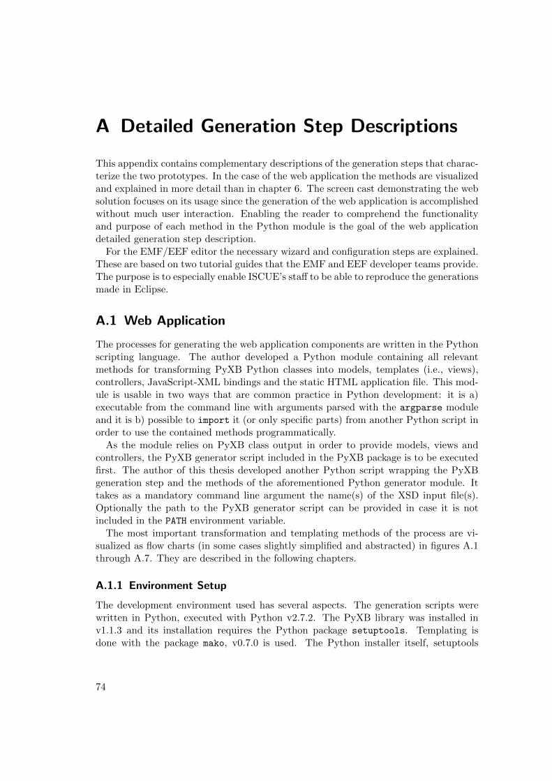
A Detailed Generation Step Descriptions
This appendix contains complementary descriptions of the generation steps that charac-terize the two prototypes. In the case of the web application the methods are visualizedand explained in more detail than in chapter 6. The screen cast demonstrating the websolution focuses on its usage since the generation of the web application is accomplishedwithout much user interaction. Enabling the reader to comprehend the functionalityand purpose of each method in the Python module is the goal of the web applicationdetailed generation step description.
For the EMF/EEF editor the necessary wizard and configuration steps are explained.These are based on two tutorial guides that the EMF and EEF developer teams provide.The purpose is to especially enable ISCUE’s staff to be able to reproduce the generationsmade in Eclipse.
A.1 Web Application
The processes for generating the web application components are written in the Pythonscripting language. The author developed a Python module containing all relevantmethods for transforming PyXB Python classes into models, templates (i.e., views),controllers, JavaScript-XML bindings and the static HTML application file. This mod-ule is usable in two ways that are common practice in Python development: it is a)executable from the command line with arguments parsed with the argparse moduleand it is b) possible to import it (or only specific parts) from another Python script inorder to use the contained methods programmatically.
As the module relies on PyXB class output in order to provide models, views andcontrollers, the PyXB generator script included in the PyXB package is to be executedfirst. The author of this thesis developed another Python script wrapping the PyXBgeneration step and the methods of the aforementioned Python generator module. Ittakes as a mandatory command line argument the name(s) of the XSD input file(s).Optionally the path to the PyXB generator script can be provided in case it is notincluded in the PATH environment variable.
The most important transformation and templating methods of the process are vi-sualized as flow charts (in some cases slightly simplified and abstracted) in figures A.1through A.7. They are described in the following chapters.
A.1.1 Environment Setup
The development environment used has several aspects. The generation scripts werewritten in Python, executed with Python v2.7.2. The PyXB library was installed inv1.1.3 and its installation requires the Python package setuptools. Templating isdone with the package mako, v0.7.0 is used. The Python installer itself, setuptools
74
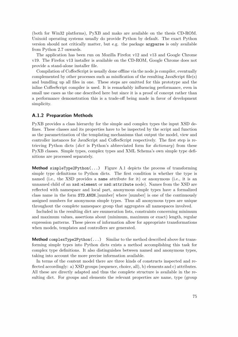
(both for Win32 platforms), PyXB and mako are available on the thesis CD-ROM.Unixoid operating systems usually do provide Python by default. The exact Pythonversion should not critically matter, but e.g. the package argparse is only availablefrom Python 2.7 onwards.
The application has been run on Mozilla Firefox v12 and v13 and Google Chromev19. The Firefox v13 installer is available on the CD-ROM, Google Chrome does notprovide a stand-alone installer file.
Compilation of CoffeeScript is usually done offline via the node.js compiler, eventuallycomplemented by other processes such as minification of the resulting JavaScript file(s)and bundling up all files in one. These steps are omitted for this prototype and theinline CoffeeScript compiler is used. It is remarkably influencing performance, even insmall use cases as the one described here but since it is a proof of concept rather thana performance demonstration this is a trade-off being made in favor of developmentsimplicity.
A.1.2 Preparation Methods
PyXB provides a class hierarchy for the simple and complex types the input XSD de-fines. These classes and its properties have to be inspected by the script and functionas the parametrization of the templating mechanisms that output the model, view andcontroller instances for JavaScript and CoffeeScript respectively. The first step is re-trieving Python dicts (dict is Python’s abbreviated form for dictionary) from thesePyXB classes. Simple types, complex types and XML Schema’s own simple type defi-nitions are processed separately.
Method simpleType2Python(...) Figure A.1 depicts the process of transformingsimple type definitions to Python dicts. The first condition is whether the type isnamed (i.e., the XSD provides a name attribute for it) or anonymous (i.e., it is anunnamed child of an xsd:element or xsd:attribute node). Names from the XSD arereflected with namespace and local part, anonymous simple types have a formalizedclass name in the form STD ANON [number] where [number] is one of the continuouslyassigned numbers for anonymous simple types. Thus all anonymous types are uniquethroughout the complete namespace group that aggregates all namespaces involved.
Included in the resulting dict are enumeration lists, constraints concerning minimumand maximum values, assertions about (minimum, maximum or exact) length, regularexpression patterns. These pieces of information allow for appropriate transformationswhen models, templates and controllers are generated.
Method complexType2Python(...) Similar to the method described above for trans-forming simple types into Python dicts exists a method accomplishing this task forcomplex type definitions. It also distinguishes between named and anonymous types,taking into account the more precise information available.
In terms of the content model there are three kinds of constructs inspected and re-flected accordingly: a) XSD groups (sequence, choice, all), b) elements and c) attributes.All these are directly adapted and thus the complete structure is available in the re-sulting dict. For groups and elements the relevant properties are name, type (group
75
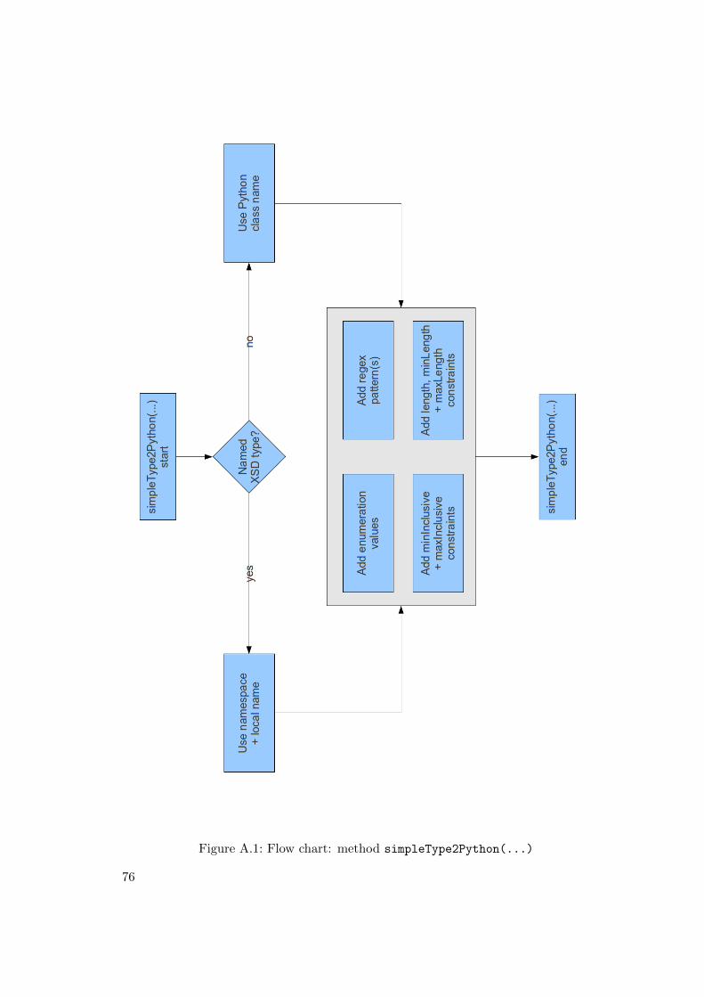
Figure A.1: Flow chart: method simpleType2Python(...)
76
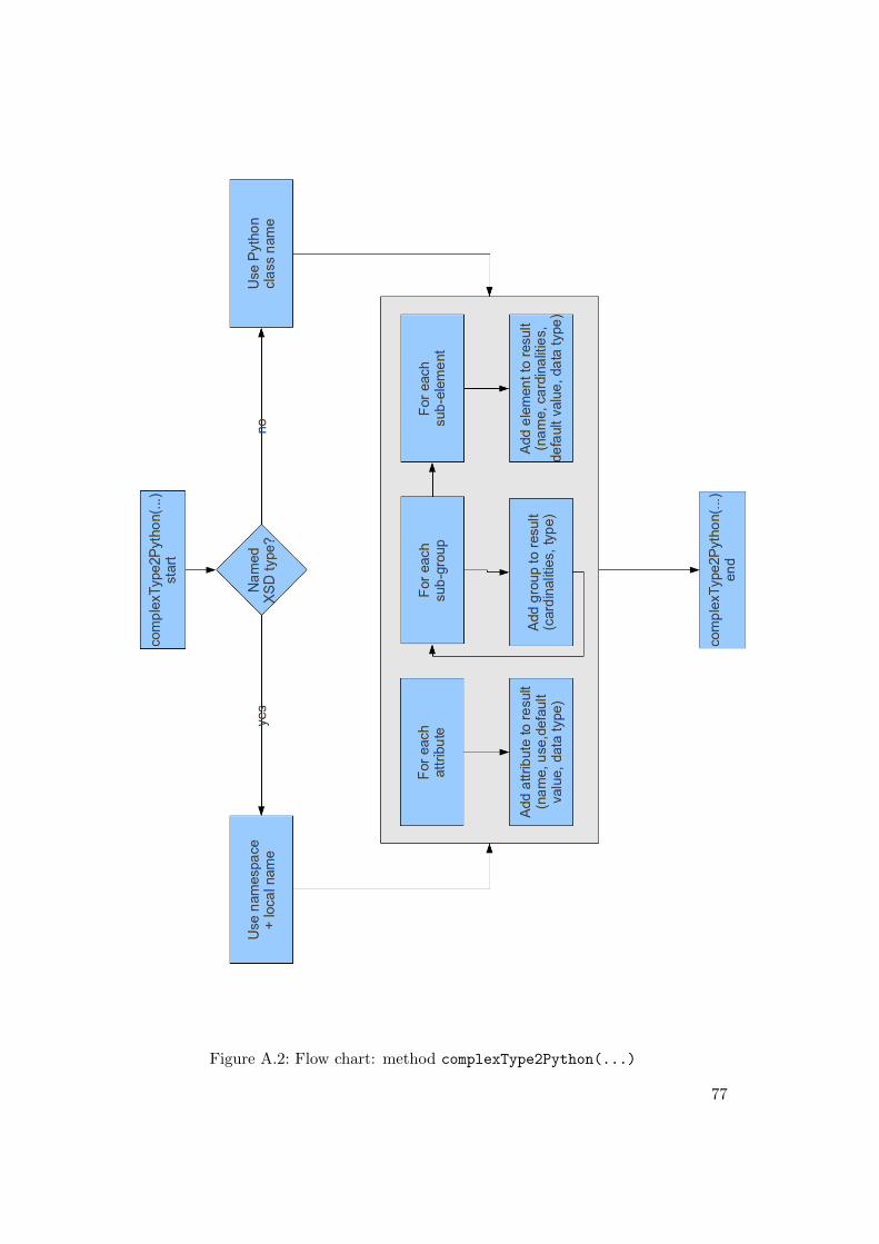
Figure A.2: Flow chart: method complexType2Python(...)
77
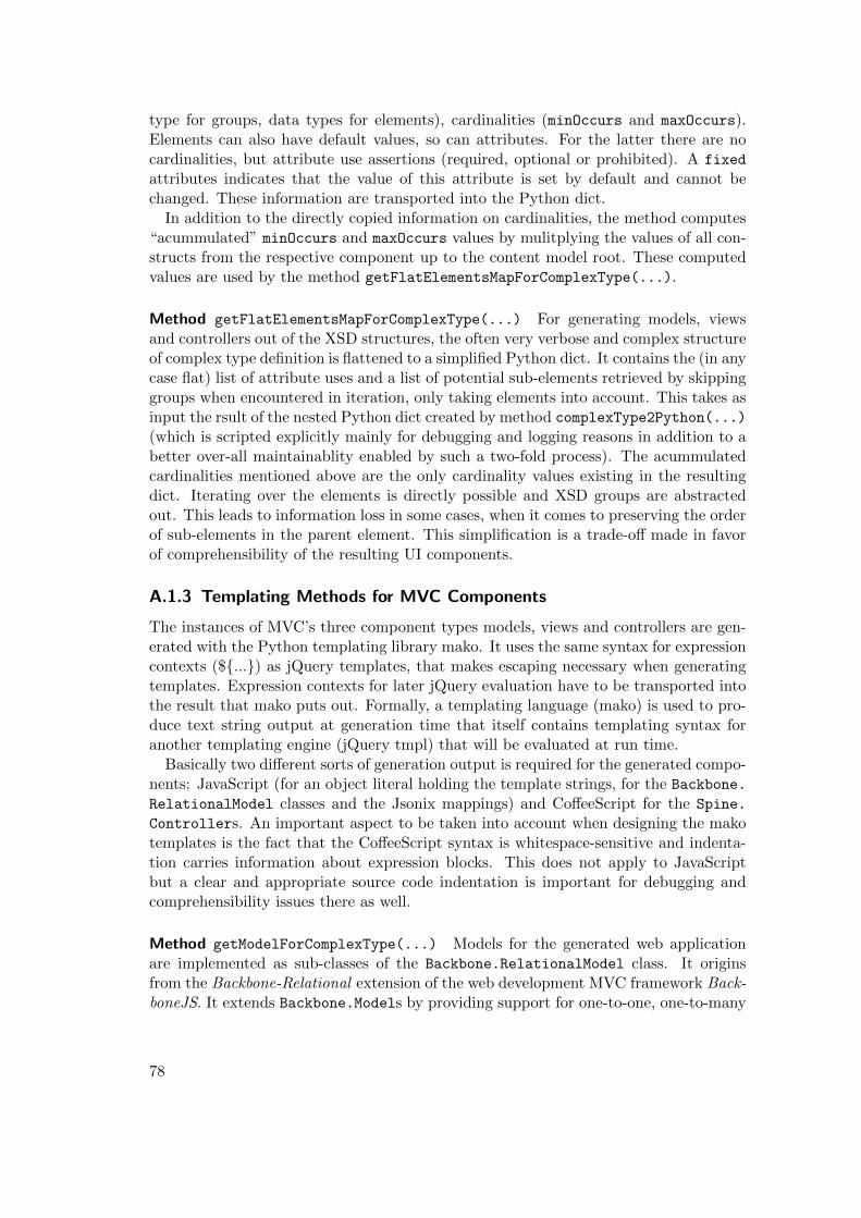
type for groups, data types for elements), cardinalities (minOccurs and maxOccurs).Elements can also have default values, so can attributes. For the latter there are nocardinalities, but attribute use assertions (required, optional or prohibited). A fixed
attributes indicates that the value of this attribute is set by default and cannot bechanged. These information are transported into the Python dict.
In addition to the directly copied information on cardinalities, the method computes“acummulated” minOccurs and maxOccurs values by mulitplying the values of all con-structs from the respective component up to the content model root. These computedvalues are used by the method getFlatElementsMapForComplexType(...).
Method getFlatElementsMapForComplexType(...) For generating models, viewsand controllers out of the XSD structures, the often very verbose and complex structureof complex type definition is flattened to a simplified Python dict. It contains the (in anycase flat) list of attribute uses and a list of potential sub-elements retrieved by skippinggroups when encountered in iteration, only taking elements into account. This takes asinput the rsult of the nested Python dict created by method complexType2Python(...)
(which is scripted explicitly mainly for debugging and logging reasons in addition to abetter over-all maintainablity enabled by such a two-fold process). The acummulatedcardinalities mentioned above are the only cardinality values existing in the resultingdict. Iterating over the elements is directly possible and XSD groups are abstractedout. This leads to information loss in some cases, when it comes to preserving the orderof sub-elements in the parent element. This simplification is a trade-off made in favorof comprehensibility of the resulting UI components.
A.1.3 Templating Methods for MVC Components
The instances of MVC’s three component types models, views and controllers are gen-erated with the Python templating library mako. It uses the same syntax for expressioncontexts (${...}) as jQuery templates, that makes escaping necessary when generatingtemplates. Expression contexts for later jQuery evaluation have to be transported intothe result that mako puts out. Formally, a templating language (mako) is used to pro-duce text string output at generation time that itself contains templating syntax foranother templating engine (jQuery tmpl) that will be evaluated at run time.
Basically two different sorts of generation output is required for the generated compo-nents: JavaScript (for an object literal holding the template strings, for the Backbone.
RelationalModel classes and the Jsonix mappings) and CoffeeScript for the Spine.
Controllers. An important aspect to be taken into account when designing the makotemplates is the fact that the CoffeeScript syntax is whitespace-sensitive and indenta-tion carries information about expression blocks. This does not apply to JavaScriptbut a clear and appropriate source code indentation is important for debugging andcomprehensibility issues there as well.
Method getModelForComplexType(...) Models for the generated web applicationare implemented as sub-classes of the Backbone.RelationalModel class. It originsfrom the Backbone-Relational extension of the web development MVC framework Back-boneJS. It extends Backbone.Models by providing support for one-to-one, one-to-many
78
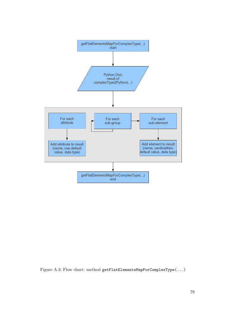
Figure A.3: Flow chart: method getFlatElementsMapForComplexType(...)
79
Figure A.4: Flow chart: method getModelForComplexType(...)
80
and many-to-many relations between model instances. Including the expanded relatedinstances into the JSON serialization automatically belongs to the features this classbrings. The relations entry in such a Backbone.RelationalModel holds informationabout all out-going relations. In the method that is described, all complex-typed sub-elements are represented as entries in this relations component of the model definition.The key is the name for addressing the related instances, relatedModel references themodel of which the related instance are. Property includeInJSON is used to assertwhether to include complete instances as properties in the serialization, only specificfields or nothing at all. Defining the relation type, type can take one of the valuesBackbone.HasOne and Backbone.HasMany. In this context, Backbone.HasMany is al-ways used due to easier maintainablity when setting/adding concrete relation values.Potential reverse relations that can be asserted that lead to automatic addition of therespective reverse direction are not used in this application context since there is nocorresponding feature in the XSD and no such direct need arose in the developmentphase.
All simple-typed sub-elements and all attributes get an entry in the defaults classcomponent. When default values de facto exist, they are set on the respective elemen-t/attribute, otherwise an empty array is asserted for repeatable elements/attributes, ornull if none of these cases apply.
The model class source code is generated as JavaScript code. BackboneJS does sup-port CoffeeScript but the Backbone-Relational extension does not completely conformto the paradigms CoffeeScript introduces (e.g., native class support emulation). Thisis the reason for choosing JavaScript directly as the target language for model classdefinitions.
Method getTemplateForComplexType(...) Templates take the role of MVC views,in this case jQuery templates. For each attribute of the input type dict a jQuerytemplate call invoking the template for the data type of the respective attribute isgenerated. This jQuery template call is wrapped in a jQuery template conditionalstatement checking for the existence of a value for this data field. Nota bene: thisjQuery template conditional and template call will be executed at runtime, only themako templates are directly evaluated in the Python script.
For each simple-typed sub-element of the type jQuery template calls are generatedanalogously to the ones generated for attributes in all cases where an element has avalue for minOccurs > 1 (i.e., it is required). Such jQuery template calls are includedfor minOccurs times. This ensures the existence of form elements for at least therequired number of such sub-elements. Such expansion is an element of user guidancethat can help ensure the entry of valid data for elements. Buttons for adding instancesof complex-typed sub-elements complement the template calls.
Method getControllerForComplexType(...) Controllers, as the third kind of com-ponent in the MVC paradigm, are generated as CoffeeScript classes extending Spine.
Controller. Spine, similar to BackboneJS (note the similarity in terms of nomencla-ture metaphors of both frameworks), provides constructs for defining MVC components.Spine is in most cases more light-weight, BackboneJS does not directly implement a
81
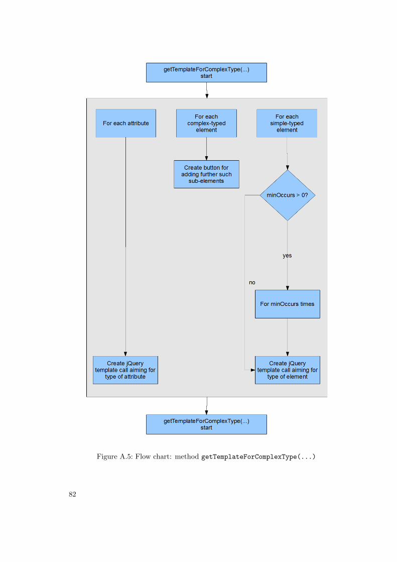
Figure A.5: Flow chart: method getTemplateForComplexType(...)
82
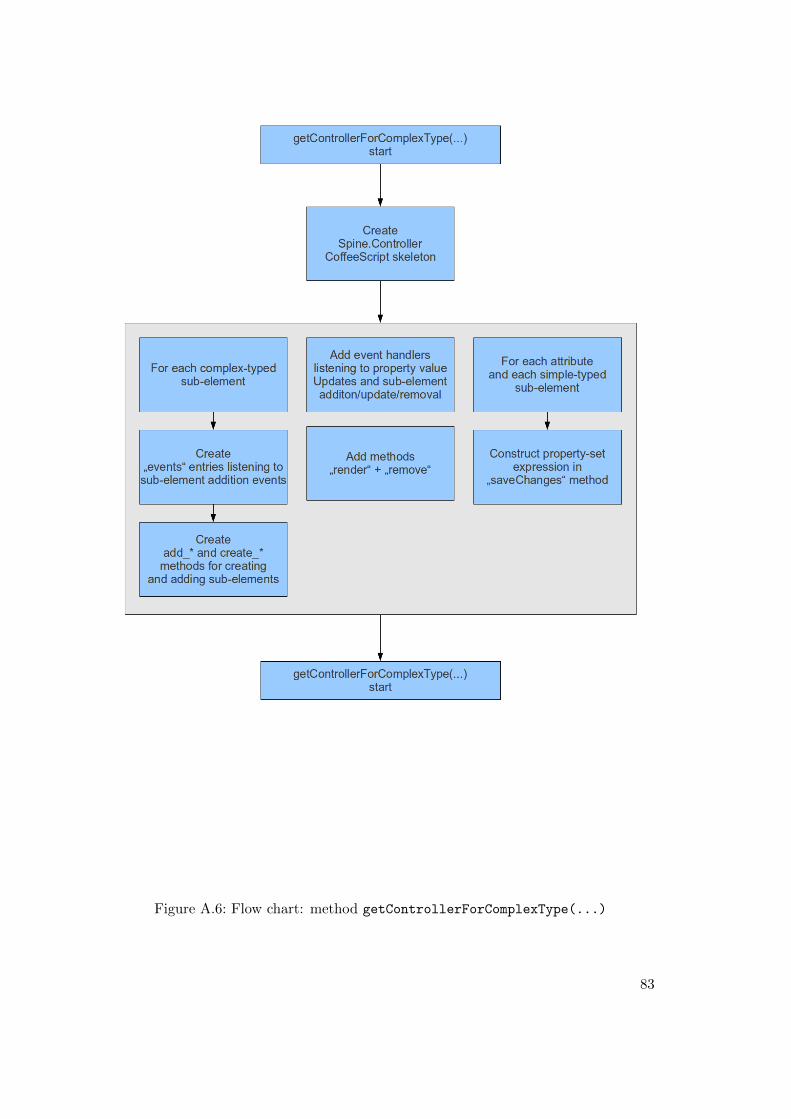
Figure A.6: Flow chart: method getControllerForComplexType(...)
83
Controller class but includes controller-like functionality in its views, that it explicitlyholds in JavaScript (or CoffeeScript) objects, contrary to Spine.
The basic parts of Spine.Controllers that are generated by this method are a)the events map declaring events to listen to, add * and create * methods for adding(complex) sub-elements and their respective controllers, the constructor function, meth-ods for rendering and removing and the save changes method for setting the attributevalues.
Method getAppController(...) In addition to the type-specific controllers that areresponsible for their attached items there needs to exist an application controller beingthe entry point into the application. It instantiates the top-level element controller(s).
For every possible top-level element the generator designates code fragments, all ofwhich are commented by default. The application is only functional when one of thesefragments is un-commented.
The application controller gets a doOutputSource method that is triggered wheneverthe static “get data” button is clicked. Its purpose is to gather the data from the editor’smodel instance (in fact, the application controller’s item), convert it to JSON, invokethe Jsonix marshaller with this JSON data, beautify the resulting XML data with thevkbeautify script and output the pretty-printed XML data to the right-hand textareaon the applications interface.
Necessary for marshalling specific JSON data structures are mappings conforming tothe Jsonix library. These are generated along with models, views and controllers.
A.1.4 Additional Generation Methods
Method getJsonixMappingForComplexType(...) Jsonix provides a script evaluat-ing JavaScript objects as the basis for JSON-to-XML mappings. This method generatessuch a mapping object for each complex XSD type. Figure A.7 depicts the process.First of all, a declaration for each type has to be generated in order to make typesreferencable. This declaration only sets an object and attaches a name property to it.
After the declarations generation all complex types are iterated again and for eachtype all sub-elements and attributes are asserted with their respective names anddata types. Since Jsonix does not fully support XML Schema’s simple data types,only Boolean is specifically resolved as such, all other simple types are resolved toxsd:strings. This does not limit the serialization functionality since validation is notpart of Jsonix’ functionality anyway.
The last piece of information needed by Jsonix’ marshalling and unmarshalling pro-cesses is a list of possible top-level elements. These are iterated and a name-type relationis appended for each.
Method getHTMLStaticFile(...) The static part of the application is generated bythis method. It concatenates strings for the HTML header, the controllers and theHTML body. The script includes in the header are
• jQuery,• jQuery templates plugin,
84
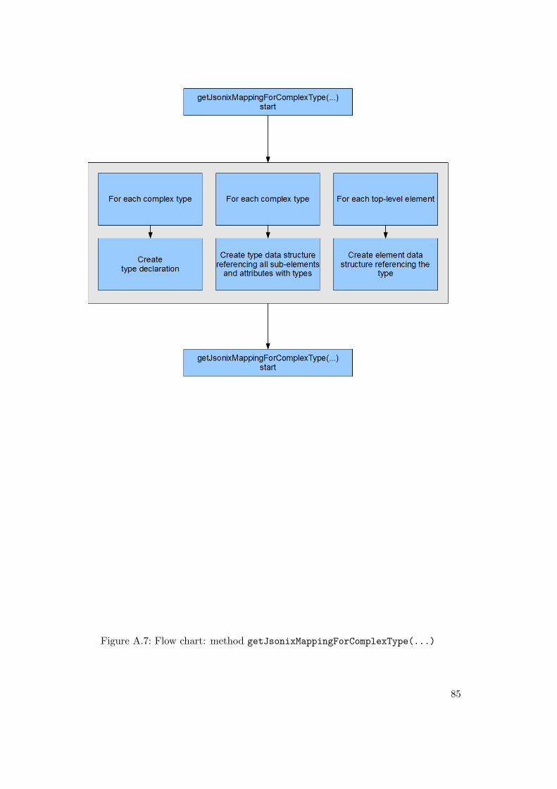
Figure A.7: Flow chart: method getJsonixMappingForComplexType(...)
85
• the inline CoffeeScript compiler script,• Spine,• UnderscoreJS (required by BackboneJS),• BackboneJS,• Backbone-Relational,• the Jsonix library,• the application’s Jsonix mapping file,• vkbeautify as the used XML beautifying script,• the application’s models and• the application’s templates.
The content of the HTML file is only depending on the controllers for the application,which are directly inserted into a CoffeeScript <script> element. All other content isstatically put out into the file.
A.2 Eclipse-Based
A.2.1 Environment Setup
The Eclipse IDE was used in version 3.7 Indigo with modelling components on bothUbuntu Linux (32 bit) and Windows 7 (32 bit). The archive files for these releases canbe found on the thesis’ CD-ROM in the eclipse folder.
EMF and EEF were bundled with these releases, EMF in version 2.7.0 and EEF inversion 1.0.2.
A.2.2 Eclipse Modeling Framework (EMF)
Prior to any of the EMF-specific generation steps it is useful23 to disable the creationof Ecore FeatureMaps. These are incorrectly handled by EEF in the later generationsteps, so their creation is suppressed in the first place. EMF creates FeatureMapsfor repeatable (i.e., with maxOccurs > 1) XSD content groups and mixed complextypes. These have to be complemented in the original XML Schema with the attributeecore:FeatureMap="" in order to prevent EMF from building FeatureMaps for them.
The tutorial [Ecl06a] was used for these steps. It explains the prerequisites that arenecessary when generating an EMF plugin for Eclipse. The plugin packages
• org.eclipse.emf.common,• org.eclipse.emf.ecore,• org.eclipse.emf.mapping and• org.eclipse.emf.codegen
have to be installed. This can be checked through the plugin overview Eclipse providesunder Help / About Eclipse / Installation Details / Plugins.
Using the XSD-to-EMF wizard starts with creating a new project. The type of theproject has to be EMF Project, listed below the Eclipse Modeling Framework group in
23It proved to be even necessary to do so in case of the combination of EMF and EEF in the PrIMLuse case.
86
the wizard for project creation. Entering a unique project name and proceeding leadsto the choice of which model type to use for the EMF plugin. Ecore, Rose, UML andXML Schema are possible, for this use case XML Schema is chosen. The next steprequires the path to the XML Schema file that should be used. It can either be resolvedfrom the workspace if it already exists in it or from any other path in the file system.In case the desired XML Schema definition is separated into more than one XSD file, itis useful to choose the master XSD file that (directly or indirectly) imports the otherXSDs. (The PrIML vocabulary for example is separated into seven (eight when takingPrIOF into account as well) files which are all (most of them directly, some indirectly)referenced (via xsd:import statements) from the PrIML Schema.xsd file.)
While loading the respective XSD file(s) the wizard is blocked from user interaction.When it finishes loading the input field Generator model file name has been filled in.The default value is the XSD local file name with an extension set to .genmodel. Theoption Create XML Schema to Ecore Map has to be checked in order to generate themapping needed for serialization and de-serialization.
The following overview lists the Java packages that have been built for the namespacesresolved from the input XSD(s). All packages that shall be included in the plugin haveto be checked. The same applies to the list below showing referenced namespaces.Clicking the Finish button creates a project with the name entered at the beginning ofthe wizard. It contains a Java Runtime Environment (JRE), a model folder containinga .ecore, .genmodel and .xsd2ecore model file for each of the packages created fromthe input XSD(s) and a source folder (src) holding the generated Java source code filesfor the elements, simple types and complex types.
Opening the .ecore model can be done with an XML editor or with the SampleEcore Model Editor for a tree view reflecting the Ecore model derived from the XMLSchema model input. Renaming of types and attributes can be applied there, datatypes or constraints of attributes can be customized. All facets that Ecore provides arereflected in the property view describing the model components.
The .genmodel holds meta data about the generation steps that follow this model-to-model (i.e., XSD to Ecore) and the basic model-to-code transformation (Ecore toJava classes). A possible configuration that can be taken in the .genmodel is settingthe Create Child option to false for features that shall not be shown in the EMF (andespecially later to-come EEF) tree view. Right-clicking the .genmodel’s tree view rootelement provides five Generate ... options. Clicking Generate All invokes all possibleEMF generation steps in the logical order they require. This creates three more projectsin the workspace, next to the basic EMF project just generated: [project name].edit,[project name].editor and [project name].tests (where [project name] is a wild-card for the originally chosen EMF generation project name).
Forming the edition basis for the generated classes, the .edit project contains Item-Providers for all types in the model. ItemProviders enable other classes and processesto view and edit instances of the classes the input model introduces. They provide con-tent and labels and handle notifications in case of changes/updates (for ItemProviderscf. [Ste09], pp. 46ff.).
The .editor project is the working plugin executable in the Eclipse workbench. Itcan be executed by right-clicking it and choosing Run As / Eclipse Application. Thiscauses a second Eclipse instance (the workbench) to open in which the editor plugin is
87
running.
A.2.3 Extended Editing Framework (EEF)
In the Eclipse Modeling Framework Technology (EMFT) project exist several othersub-projects complementing EMF Core. One highly relevant to the approach taken inthis thesis is EEF with its generation steps on top of EMF plugins.
The tutorial [Ecl12b] was used for the following generations. It demands to applythe steps of the installation guide. The respective update sites for stable and nightlybuilds of EEF are linked there; EEF needs to be installed if not already availablethrough Eclipse’s modelling component set (see chapter A.2.1). When EEF is properlyinstalled, the tutorial steps can be applied to an EMF plugin set as the result of chapterA.2.2.
First a destination folder for EEF’s models needs to be set up. The tutorial recom-mends to call it models, attempting to keep consistency to the EMF model folder, it canbe called model (singular form). It is placed in the .edit plugin project. Right-clickingon the EMF .genmodel file opens the context menu with the menu item EEF / InitializeEEF models. Applying this step leads to a wizard asking for the just created destinationfolder for the EEF models. Confirmation causes the creation of a .components and a.eefgen model.
The next step is creating a new source folder in the .edit project. Note that ausual folder (Right-click / New / Folder) does not suffice, choose Right-click / New /Source Folder instead and the name has to be src-gen, which is a common practice insoftware component generation. Before generating the source code, the EEF runtimepackage (org.eclipse.emf.eef.runtime) has to be added to .edit’s plugin.xml file.Open it with the Plugin Manifest Editor and choose the Runtime tab. After addingthe package open its properties and check the Reexport this dependency in order tomake the EEF runtime package available to further plugins, namely .editor. Afterthese configurations right-click the generated .eefgen model and choose the EEF /Generate EEF architecture option.
Due to a reported bug in the used EEF version24 there are incorrect references to anon-existing Java class EStringToStringMapEntry in every .edit/src-gen/*/components/DocumentRootPropertiesEditionComponent.java file. Changing the references to theimplementation class EStringToStringMapEntryImpl is the recommended solution andit indeed solves the errors caused by the otherwise false references. The adjusted meth-ods can be marked with @generated NOT tags in order to preserve the change whenregenerations are applied.
When the generation is finished, the plugin.xml file in the .edit project has to beopened with the Eclipse manifest editor. On the runtime tab, the generated *.providersclasses have to be added. After that, re-opening the same plugin.xml file with the XMLor text editor is needed in order to paste the content of the generated * properties.plugin.xml file(s) into the plugin.xml.
The last manual step in EEF’s enhancement is overwriting some existing class meth-ods and one property in the *Editor.java class in the .editor project. See the original
24cf. http://www.eclipse.org/forums/index.php/mv/msg/206326/660537/
88

tutorial on the thesis CD-ROM for the exact methods and property to replace.After these generation, dependency configuration and manual copy-paste steps the
.editor plugin is enhanced with form-based property views and data entry dialogwindows. All further customizations are optional, some of the ones attempted in thecontext of this thesis are described in chapter 6.3.2.
89
B Thesis CD-ROM Contents
The CD-ROM accompanying this thesis contains resources and material used and/orproduced in the context of the thesis. See the following list for detailed information:
• The thesis PDF• Source code
– PrIML XML Schema collection– PrIML subset isolated for better development maintainability– Web Application Generator∗ Self-developed, commented Python module pyxb to mvc web app and
helper script generate.py together with library files∗ Generated application for PrIML subset
– EMF/EEF∗ Workspace copy containing EMF editor∗ Workspace copy containing EEF editor∗ Workspace copy containing customized EEF editor∗ Saved tutorial used for EEF generation and setup
• Eclipse Modeling Components package installer (Windows 32-bit)• Python development environment used
– Python v2.7.2– Python package pyxb v1.1.3– Python package setuptools v0.6c11– Python package mako v0.7.0
• Mozilla Firefox v13 installer (Windows 32-bit)• PrIML XSDs and visualizations as .png files• Screen casts of generation processes, some customizations and basic editor usage
90