Embed Size (px)
Citation preview
FMEA Harmonisierung
Conclusio des U.S. Fachspezialisten Richard Harpster:
„There is still considerable resistance to the VDA tree methodologyin the U.S. If it is ever adopted, it will put FMEAs back 20 years.“
Harpster ist eine Ikone des amerikanischen FMEA Risk ManagementBusiness.
Wir veröffentlichen die detaillierte Expertise zur „Harmonisierung“auf den folgenden Seiten mit seinem ausdrücklichen schriftlichenEinverständnis.
Sämtliche Copyright-Rechte an den Inhalten liegen beim Autor.Auch wenn wir voll mit seiner Überzeugung übereinstimmen,machen wir uns das repräsentierte Know How der fachlichenAusführungen expressis verbis nicht zu eigen.
Die wichtigsten Passagen der Fachpublikationen haben wir nacheigenem Ermessen gelb hervorgehoben.
MBFG MAGAZIN Ausland.
The Case Against the AIAG-VDA DFMEA
Limitations of Throttle Positioner Example Found in VDA Manual
Unfortunately, the Throttle Positioner example found in the 2012 VDA manual is incomplete.The 2012 VDA Manual does not develop the Failure Analysis (2012 VDA Manual Figure 2.8.3.1-1, page 40) for all the branches of the Throttle Positioner Structure Analysis (2012 VDA ManualFigure 2.8.1.1-2, page 36) and Function Analysis (2012 VDA Manual Figure 2.8.2.1-1, page38). If the instructions for the creation of the VDA DFMEA found in the 2012 VDA Manual areproperly followed, four different DFMEAs are required (Throttle Positioner, Transmission,Primary Gear, Primary Gear Axis). The 2012 VDA Manual provides only two entries of thePrimary Gear DFMEA while providing nothing on the other three DFMEAs.
Because of limitations on the information in the 2012 VDA Manual, the following steps will betaken:
1. The paper will be limited to developing Design FMEA entries only for the entries found inthe Throttle Positioner Failure Analysis.
2. Since a DFMEA does not exist in the 2012 VDA Manual for the Throttle Positionerelement, the effects for the Throttle Positioner failure (“Air opening not enlarged despiteactuation”) found in the Failure Analysis will be derived from the Primary Gear DFMEAand Severity Ratings table (2012 VDA Manual A4.1, page 117).
3. Prevention and Detection controls for non-existent DFMEAs will be listed as TBD (To BeDetermined).
4. All Occurrence ratings are set to 1 except for those defined in the Primary Gear DFMEAfound in the 2012 VDA Manual.
Required Information in DFMEA to Manage Risk
The primary task of the design engineer is to create a set of Product Design Specifications thatdefine a product that will meet the Product Design Requirements. The Product DesignSpecifications contain the information required for manufacturing to build the product. Theyinclude dimensional and material specifications as well as required software code if applicable. Due to the wide variety of Product Design Requirements a product might have and the factthat some of the Product Design Requirements can be competing, it is often impossible for thedesign engineer to define Product Design Specifications that define a product which will meetall the Product Design Requirements all the time. All designs have risk when they are releasedfor manufacture.
When done properly, the DFMEA is a structured risk assessment of the adequacy of the ProductDesign Specifications in defining a product that will meet the Product Design Requirements. Itenables the design engineer to identify the product failures that can occur and the ProductDesign Specifications that control whether the failures will happen. When properly performed,the Design FMEA allows the design engineer to identify the Product Design Specifications thatmust be risk optimized to reduce the design risk to a level that is acceptable to both thecustomer and company.
For a line of a DFMEA to be used to manage risk, two conditions must be present. First, theProduct Design Requirement placed in the Requirement column and the failure mode must be
verifiable. Secondly, the entry in the Failure Cause column of each line of the DFMEA mustcontain a Product Design Specification condition that may be causing the Failure Mode. TheProduct Design Specification condition is known as the potential “root cause” of risk exposuredefined by the DFMEA line.
Using the Proposed AIAG-VDA Handbook DFMEA Methodology to Manage Risk
In the Handbook DFMEA Method, the Design Requirements, Failure Modes, Effects and Causesare not entered directly into the DFMEA. They are derived from a Structure Analysis, FunctionAnalysis and Failure Analysis.
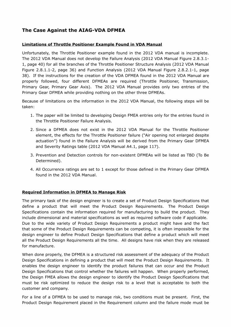
The first step is to create a Structure Analysis. When constructing the Structure Analysis, theAssembly, Sub-Assembly(s) and Component(s) are known as elements. The parent-childrelationships between the elements are shown graphically. The characteristics of thecomponents that control the Components performance are also shown. Following is theStructure Analysis for the Throttle Positioner found in the 2012 VDA Manual (Note: Onlyelements referenced in the Failure Analysis (2012 VDA Manual Figure 2.8.3.1-1, page 40) areshown).
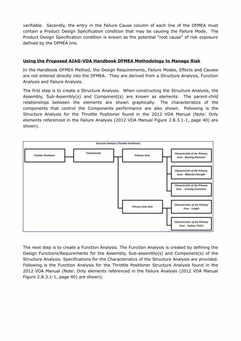
The next step is to create a Function Analysis. The Function Analysis is created by defining theDesign Functions/Requirements for the Assembly, Sub-assembly(s) and Component(s) of theStructure Analysis. Specifications for the Characteristics of the Structure Analysis are provided.Following is the Function Analysis for the Throttle Positioner Structure Analysis found in the2012 VDA Manual (Note: Only elements referenced in the Failure Analysis (2012 VDA ManualFigure 2.8.3.1-1, page 40) are shown).
Once the Function Analysis has been created the next step is to construct the Failure Analysis.The Function Analysis is created by defining the failures for the functions of the Assembly, Sub-assembly(s) and Component(s) of the Function Analysis. When constructing the FailureAnalysis, each failure must be described in terms of the level at which it occurs. Objectionablecondition(s) of the Characteristics that could lead to the component failure are provided.
Following is the Failure Analysis for the Throttle Positioner Structure Analysis found in the 2012VDA Manual (2012 VDA Manual Figure 2.8.3.1-1, page 40).
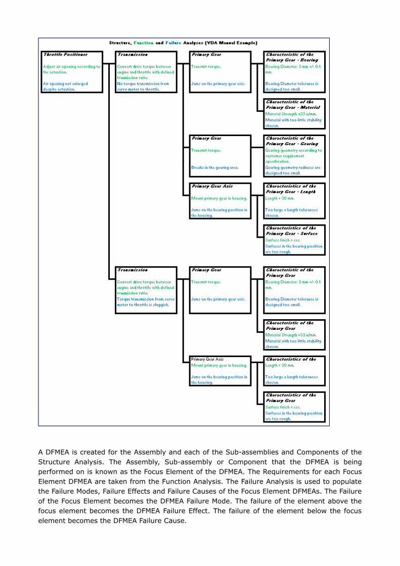
A DFMEA is created for the Assembly and each of the Sub-assemblies and Components of theStructure Analysis. The Assembly, Sub-assembly or Component that the DFMEA is beingperformed on is known as the Focus Element of the DFMEA. The Requirements for each FocusElement DFMEA are taken from the Function Analysis. The Failure Analysis is used to populatethe Failure Modes, Failure Effects and Failure Causes of the Focus Element DFMEAs. The Failureof the Focus Element becomes the DFMEA Failure Mode. The failure of the element above thefocus element becomes the DFMEA Failure Effect. The failure of the element below the focuselement becomes the DFMEA Failure Cause.
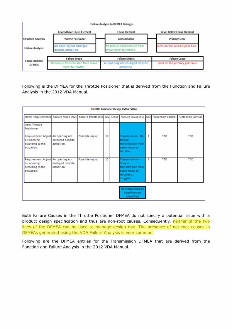
Following is the DFMEA for the Throttle Positioner that is derived from the Function and FailureAnalysis in the 2012 VDA Manual.
Both Failure Causes in the Throttle Positioner DFMEA do not specify a potential issue with aproduct design specification and thus are non-root causes. Consequently, neither of the twolines of the DFMEA can be used to manage design risk. The presence of not root causes inDFMEAs generated using the VDA Failure Analysis is very common.
Following are the DFMEA entries for the Transmission DFMEA that are derived from theFunction and Failure Analysis in the 2012 VDA Manual.
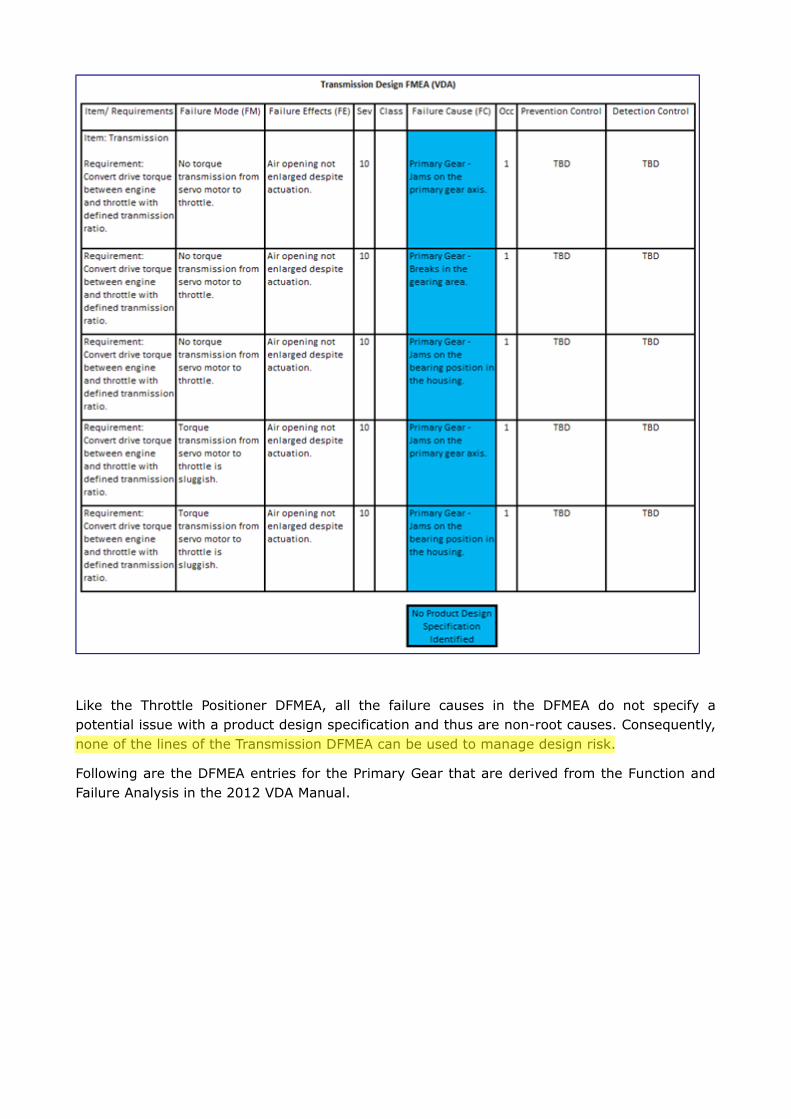
Like the Throttle Positioner DFMEA, all the failure causes in the DFMEA do not specify apotential issue with a product design specification and thus are non-root causes. Consequently,none of the lines of the Transmission DFMEA can be used to manage design risk.
Following are the DFMEA entries for the Primary Gear that are derived from the Function andFailure Analysis in the 2012 VDA Manual.
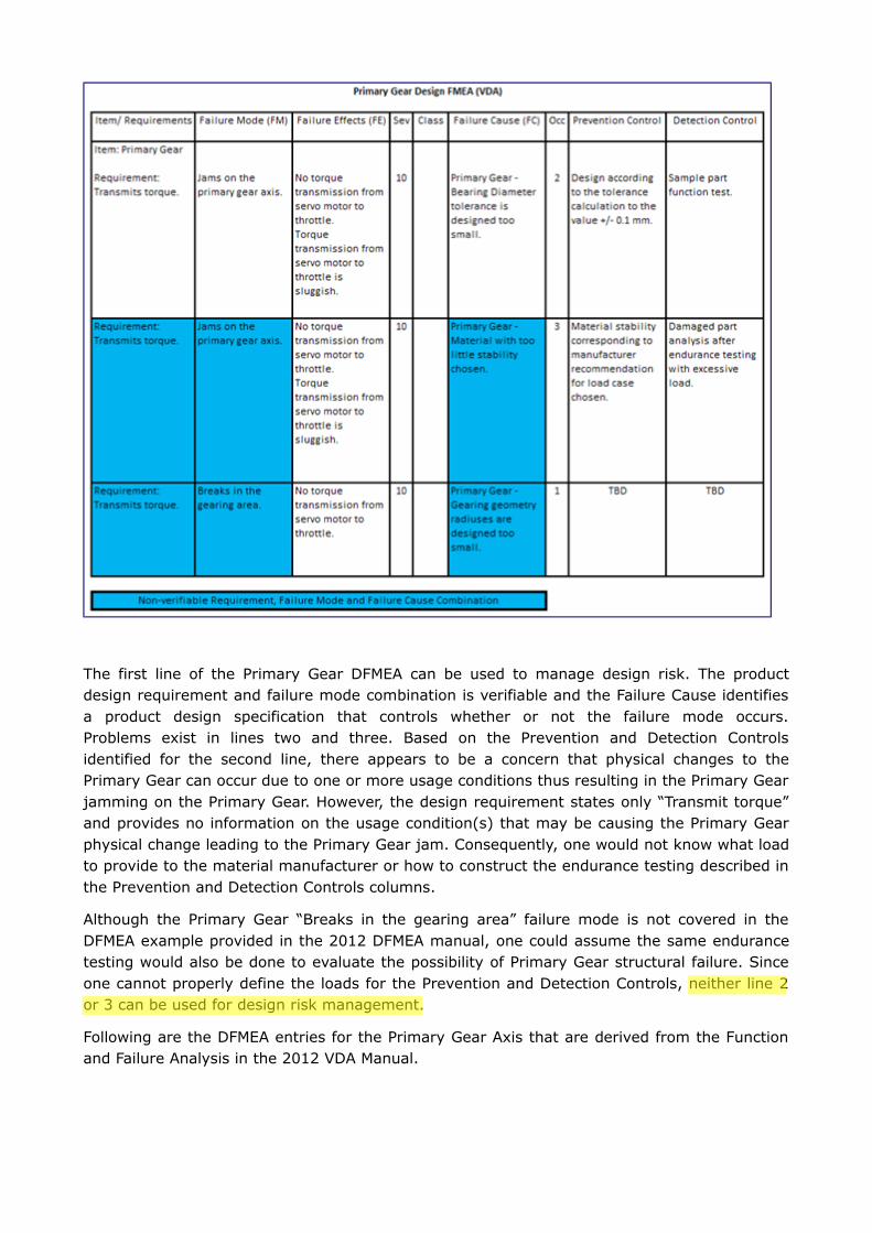
The first line of the Primary Gear DFMEA can be used to manage design risk. The productdesign requirement and failure mode combination is verifiable and the Failure Cause identifiesa product design specification that controls whether or not the failure mode occurs.Problems exist in lines two and three. Based on the Prevention and Detection Controlsidentified for the second line, there appears to be a concern that physical changes to thePrimary Gear can occur due to one or more usage conditions thus resulting in the Primary Gearjamming on the Primary Gear. However, the design requirement states only “Transmit torque”and provides no information on the usage condition(s) that may be causing the Primary Gearphysical change leading to the Primary Gear jam. Consequently, one would not know what loadto provide to the material manufacturer or how to construct the endurance testing described inthe Prevention and Detection Controls columns.
Although the Primary Gear “Breaks in the gearing area” failure mode is not covered in theDFMEA example provided in the 2012 DFMEA manual, one could assume the same endurancetesting would also be done to evaluate the possibility of Primary Gear structural failure. Sinceone cannot properly define the loads for the Prevention and Detection Controls, neither line 2or 3 can be used for design risk management.
Following are the DFMEA entries for the Primary Gear Axis that are derived from the Functionand Failure Analysis in the 2012 VDA Manual.
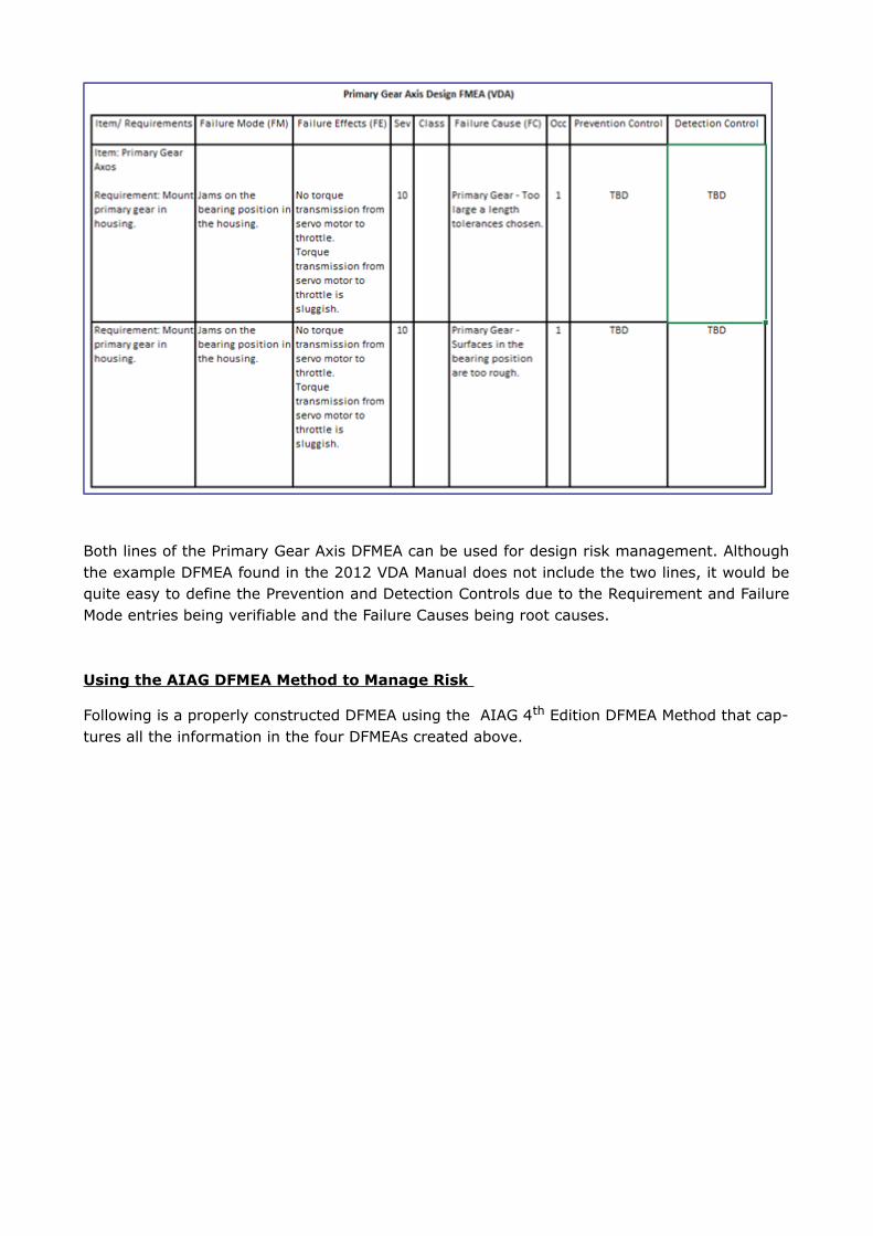
Both lines of the Primary Gear Axis DFMEA can be used for design risk management. Althoughthe example DFMEA found in the 2012 VDA Manual does not include the two lines, it would bequite easy to define the Prevention and Detection Controls due to the Requirement and FailureMode entries being verifiable and the Failure Causes being root causes.
Using the AIAG DFMEA Method to Manage Risk
Following is a properly constructed DFMEA using the AIAG 4th Edition DFMEA Method that cap-tures all the information in the four DFMEAs created above.
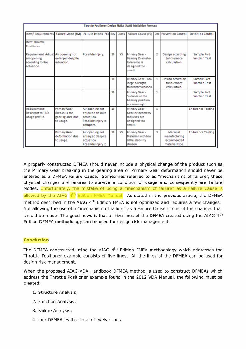
A properly constructed DFMEA should never include a physical change of the product such asthe Primary Gear breaking in the gearing area or Primary Gear deformation should never beentered as a DFMEA Failure Cause. Sometimes referred to as “mechanisms of failure”, thesephysical changes are failures to survive a condition of usage and consequently are FailureModes. Unfortunately, the mistake of using a “mechanism of failure” as a Failure Cause is
allowed by the AIAG 4th Edition FMEA Manual. As stated in the previous article, the DFMEA
method described in the AIAG 4th Edition FMEA is not optimized and requires a few changes. Not allowing the use of a “mechanism of failure” as a Failure Cause is one of the changes that
should be made. The good news is that all five lines of the DFMEA created using the AIAG 4th
Edition DFMEA methodology can be used for design risk management.
Conclusion
The DFMEA constructed using the AIAG 4th Edition FMEA methodology which addresses theThrottle Positioner example consists of five lines. All the lines of the DFMEA can be used fordesign risk management.
When the proposed AIAG-VDA Handbook DFMEA method is used to construct DFMEAs whichaddress the Throttle Positioner example found in the 2012 VDA Manual, the following must becreated:
1. Structure Analysis;
2. Function Analysis;
3. Failure Analysis;
4. four DFMEAs with a total of twelve lines.
Of the twelve DFMEA lines found in the four DFMEAs created using the AIAG-VDA DFMEAmethod only 25% or three of the lines can be used for design risk management. Two of theresultant DFMEAs have no lines that can be used for design risk management.
It is clear the AIAG 4th Edition DFMEA methodology is both more effective and more efficientthan the proposed AIAG-VDA Handbook DFMEA method. I recognize the fact that theEuropean community is highly invested in the VDA methodology and there will be heavyresistance in giving it up. However, “FMEA Process Harmonization” should not be a reason forthe US automotive industry to accept a DFMEA and PFMEA processes that are not as effectiveand efficient as the ones they already have.
About The Author
Richard Harpster
Richard Harpster is president of Harpco Systems, which he founded in 1987. Harpco Systemsspecializes in providing software, training, and consulting for risked-based product lifecycle
management (RBPLM®). During the past 30 years, Harpster has helped hundreds ofcompanies implement improved risk-based design and manufacturing systems in a widevariety of industries. He is a recognized expert in the application of FMEAs and has inventedseveral new concepts, including the linking of design FMEAs to process FMEAs in 1990, whichbecame an automotive industry standard 18 years later. His latest inventions in the field of
RBPLM® include Requirements Risk Assessment (RRA®), Usage Risk Assessment (URA™),
Multiple Integrated Cause Analysis (MICA™) and Rapid Integrated Problem Solving (RIPS®).
He has published several papers on the topic of RBPLM®.
The Case Against The AIAG-VDA PFMEA
In a previous article “The Case Against the AIAG-VDA DFMEA” proof was provided on whyadoption of the proposed Handbook DFMEA methodology would result in the implementation ofa DFMEA methodology that is considerably less effective and much more inefficient than thecurrent the AIAG 4th Edition FMEA Manual DFMEA methodology. The purpose of this paper is toshow that the adoption of the proposed AIAG-VDA Handbook PFMEA methodology would resultin similar reductions in effectiveness and increases in inefficiencies when compared to the
existing AIAG 4th Edition PFMEA process.
Purpose of a Process FMEA
All manufacturing processes have process requirements that must be met. The processrequirements include but are not limited to producing within specification product, producingproduct within a specified time and not exposing workers to injury. Risk exposure occurswhenever a process does not meet a process requirement. Due to the complexity of processesand the products which they produce, the potential sources of risk are so numerous thatcompanies do not have the time and resources to work on them all. They must beprioritized.When done properly, the Process FMEA is a structured risk assessment of theadequacy of the manufacturing process in meeting its process requirements. The PFMEAallows the manufacturing personnel to identify the potential causes of process failure that posethe greatest risk so actions can be taken to reduce the probability of them occurring to a levelthat is acceptable to both the customer and company.
Using the AIAG PFMEA method to manage risk
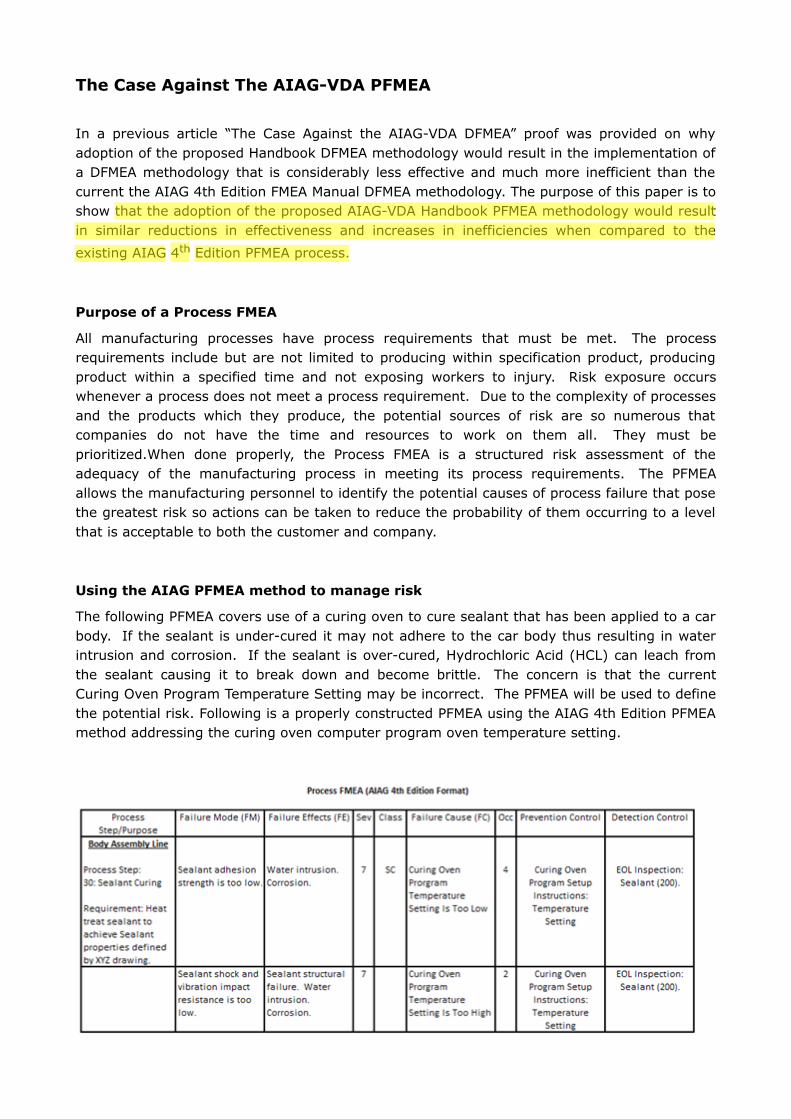
The following PFMEA covers use of a curing oven to cure sealant that has been applied to a carbody. If the sealant is under-cured it may not adhere to the car body thus resulting in waterintrusion and corrosion. If the sealant is over-cured, Hydrochloric Acid (HCL) can leach fromthe sealant causing it to break down and become brittle. The concern is that the currentCuring Oven Program Temperature Setting may be incorrect. The PFMEA will be used to definethe potential risk. Following is a properly constructed PFMEA using the AIAG 4th Edition PFMEAmethod addressing the curing oven computer program oven temperature setting.
The PFMEA accomplishes the risk assessment of the current Curing Oven Program TemperatureSetting in the following manner:
1. The first step of the PFMEA process is to define the process flow. The ProcessStep/Purpose column is used to capture each step of the process and to define theprocess requirement(s) the process step is attempting to meet (“Heat treat sealant toachieve required Sealant properties defined by XYZ drawing”).
2. The Failure Mode column is used to capture the two ways in which the process can failto meet the requirement. Two defects are identified (“Sealant adhesion strength is toolow.”, “Sealant shock and vibration resistance is too low.
3. A description of the harm that can be experienced when the failure occurs is provided inthe “Failure Effects (FE)” column (“Water Intrusion. Corrosion.”).
4. A numerical rating is placed in the “Sev” (aka “Severity”) column that corresponds tothe severity of harm described in the “Failure Effects” column (“7”).
5. The potential cause of the defect in the FM column is entered in the “Failure Cause (FC)”column (“Curing Oven program temperature setting is too low.”). To use the PFMEA tomanage risk, the FC must always be a root cause.
6. The method(s) that will be used to reduce the probability of the FC from occurring orprevent the process from running when the FC is present, is known as a “PreventionControl” (“Curing Oven Program Setup Instructions: Temperature Setting”).
7. A determination of the probability of the FM occurring due to the FC must be made. Anumerical rating equivalent to the probability is entered in the “OCC” or “Occurrence”column. One common mistake is to use the probability of the FC to determine the“OCC” rating. The presence of a FC does not guarantee the creation of a FM.
8. The “Sev” and “Occ” are looked up in a Risk Matrix that has symbols corresponding tothe level of risk indicated by the “Sev” and “Occ” ratings. The appropriate risk levelsymbol is placed in the “Class” column (“SC”). In the example PFMEA, the probability ofexperiencing low sealant adhesion strength due to the current Curing Oven ProgramOven Temperature Setting being too low is considered unacceptable.
Using the proposed handbook PFMEA methodology to manage risk
In the AIAG-VDA Handbook PFMEA Method, the processing line name, process steps, processrequirements, failure modes, effects and causes are not entered directly into the PFMEA asthey are in the AIAG 4th Edition FMEA. They are derived from a Structure Analysis, FunctionAnalysis and Failure Analysis.
The Structure Analysis is comprised of the Process Item, Process Step(s) and Process WorkElement(s). The Process Item is the name of the processing line that the PFMEA will beperformed on. The Process Step(s) are the process steps that make up the processing line. The next step in creating the Structure Analysis is to identify the Process Work Elements foreach Process Step. The Process Work Elements are categories of failure causes. There are sixdifferent categories. If you are familiar with Ishikawa Diagrams, the categories are the sixIshikawa Diagram cause category types: Machine, Man, Milieu (Environment), Material(Indirect), Method and Measurement. As an example, the Process Work Element for theexample PFMEA would be “Curing Oven (Machine)”. If an operator was referenced in ourPFMEA example, another Process Work Element would be “Operator (Man)”.
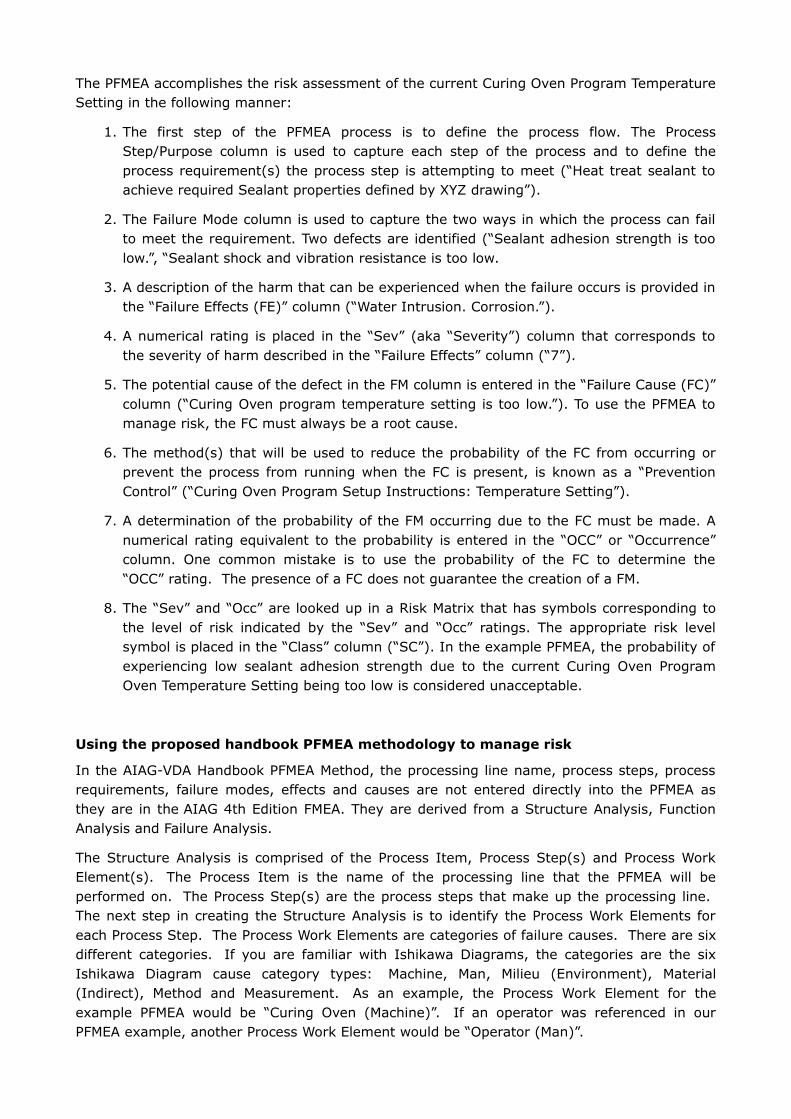
Following is the structure analysis for the PFMEA example provided.
The next step is to create a Function Analysis. The Function Analysis is created by defining thefunctions of the Process Item, Process Step(s) and Process Work Element(s). The creator ofthe Function Analysis must define functions for each of the categories of causes when definingthe functions for the Process Work Elements
Following is the function analysis for the PFMEA example for the “Failure Modes” that can becovered.
Once the Function analysis has been created the next step is to construct the Failure analysis.The Failure analysis contains the failures for the Process Item, Process Step and Process WorkElement functions.
Following is the failure analysis for the PFMEA example.
The AIAG-VDA PFMEA form was developed to support the implementation of the StructureAnalysis, Function Analysis, Failure Analysis and PFMEA. Consequently, there is additionalinformation in the Handbook PFMEA form that is not found in the AIAG 4th Edition PFMEA form.The additional information provided in the AIAG-VDA Handbook PFMEA form is not needed touse the PFMEA as a process risk management tool.

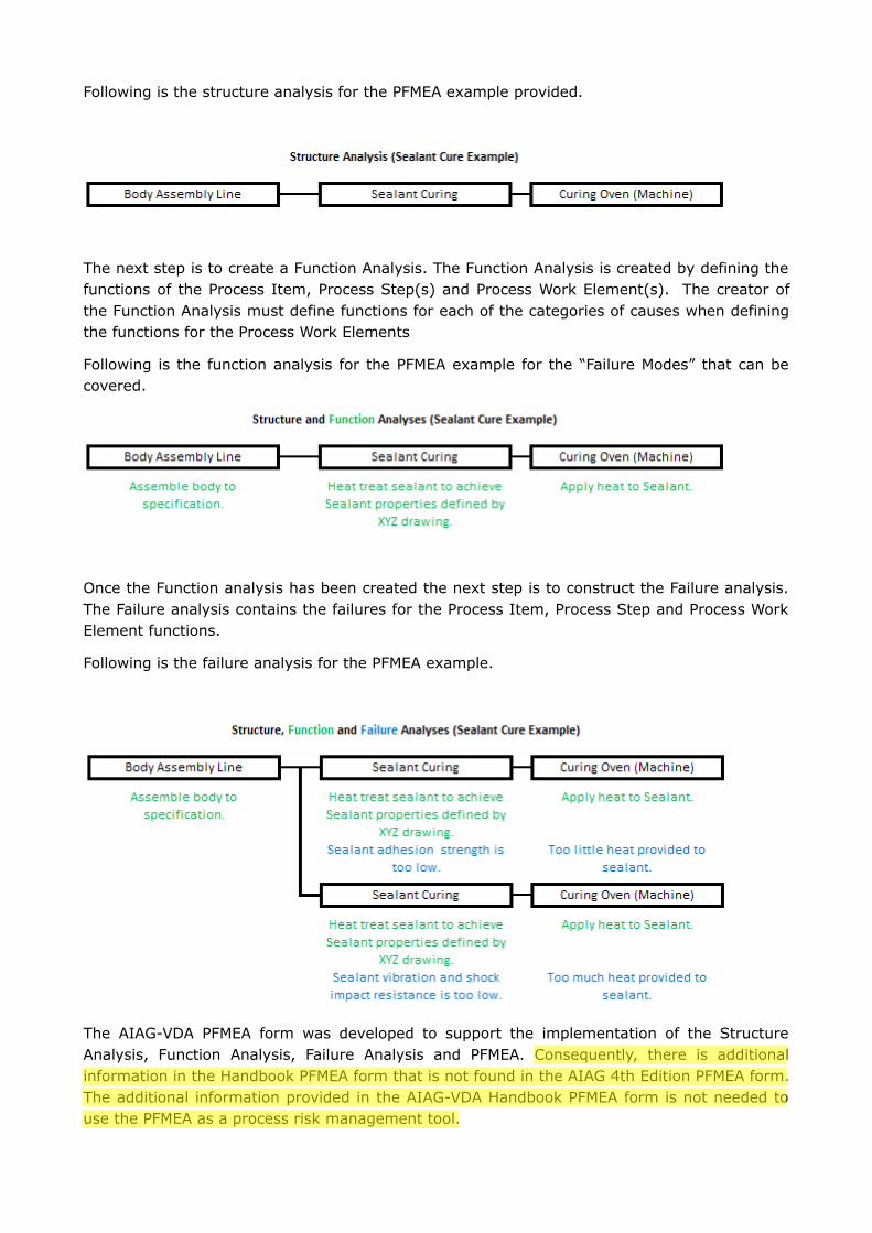
Following is information that is used to manage process risk that is common to both the AIAG-VDA PFMEA and AIAG 4th Edition PFMEA methods that is derived from the structure, functionand failure analyses. The table shows the slight difference in terminology between the headersof the two PFMEA forms. When transferring information from the structure, failure andfunction analyses to the PFMEA, the following happens:
1. the Process Step of the structure analysis becomes the “Focus Element”;
2. the Process Step function of the function analysis becomes the “Focus Element Functionand Requirement”;
3. the Process Step failure of the Failure Analysis becomes the “Failure Mode of the FocusElement”;
4. the Process Work Element failure of the Failure Analysis becomes the failure cause ofthe “Failure Mode of the Focus Element”.
5. The effects of the “Focus Element Failure Mode” are brainstormed.
A review of the contents of the AIAG-VDA PFMEA reveals the following:
1. The information provided by the Process Flow Diagram into the Structure and FunctionAnalyses is placed in the PFMEA columns in the same manner that it would have been ifthe information was transferred directly to the PFMEA from the Process Flow Diagram as
it is done when using the AIAG 4th Edition PFMEA methodology.
2. Page 83 of the AIAG-VDA FMEA Handbook defines one of the main objectives of theFailure Analysis that is used to construct the PFMEA as the “establishment of the failurefor each function”. In the case of the Curing Oven the function is to apply heat tosealant. Failures of the process step would be to apply too little or too much heat tothe sealant. In the proposed AIAG-VDA Handbook PFMEA method, these two failuresbecome failure causes in the PFMEA. The problem is they are not root causes. They
describe how the process step fails and not why the process step fails. Withoutknowing the root causes of why the process step failed, a prevention control cannot bedefined nor can the PFMEA line be used for risk management.
3. Some people use the Ishikawa diagram to define failure causes when creating a PFMEA
using the AIAG 4th Edition PFMEA methodology. Unlike the proposed AIAG-VDA PFMEAmethodology, the Ishikawa Diagram allows the user to directly identify failure causeswithout the need to define functions for the cause category that the causes fall under.When using the Ishikawa diagram, one continues ask questions until a root cause isfound. If one were using an Ishikawa diagram to determine the root cause in theexample provided, the first question that would be asked is “What can the Curing Ovendo to cause the Sealant Adhesion strength to be too low?”. The second question askwould be “Why did the Curing Oven provide too little heat to the sealant”. One answerwould be “The Curing Oven Program Temperature Setting is too low” which is a rootcause. The proposed AIAG-VDA Handbook PFMEA methodology has no space in theExcel spreadsheet to answer the second question thus you are left with a non-rootcause provided by the answer to the first question.
Conclusion
It is difficult to define one benefit of using the Structure, Function and Failure Analyses that isbeing proposed by the AIAG-VDA PFMEA methodology to populate the PFMEA form. The use ofthe Structure and Function analysis to populate the Process Step and Function/RequirementPFMEA columns forces the user to place the information in a Structure and Function Analysis soit can be used to populate the two columns rather than allowing the person performing thePFMEA to place it there directly. The proposed PFMEA methodology also forces the performerof the PFMEA to define functions for the Ishikawa Cause Categories to define the PFMEA failurecauses when the inventor of the Ishikawa Diagram, Mr. Kaoru Ishikawa, did not believe such astep is necessary. To make matters worse, when the step of defining functions for Process
Work Elements is required and the failure cause becomes a description of how the function isnot met, the Failure Cause entered into the PFMEA is most likely a non-root cause thus makingthe definition of a prevention control impossible and the line of the PFMEA useless for riskmanagement.
If the AIAG-VDA PFMEA methodology, which uses structure, function and failure analyses todetermine critical PFMEA content is implemented, it will result in an automotive PFMEA processthat is both considerably less effective and more inefficient than the current methodologydescribed in the AIAG 4th Edition FMEA Manual. A better path to standardization between VDAand AIAG Process FMEA methodologies is to accept the current AIAG 4th Edition Process FMEAmethodology as the starting core methodology and make the necessary adjustments to it toarrive at a joint AIAG-VDA Process FMEA standard.
About The Author
Richard Harpster
Richard Harpster is president of Harpco Systems, which he founded in 1987. Harpco Systemsspecializes in providing software, training, and consulting for risked-based product lifecyclemanagement (RBPLM). During the past 30 years, Harpster has helped hundreds of companiesimplement improved risk-based design and manufacturing systems in a wide variety ofindustries. He is a recognized expert in the application of FMEAs and has invented several newconcepts, including the linking of design FMEAs to process FMEAs in 1990, which became anautomotive industry standard 18 years later. His latest inventions in the field of RBPLM includeRequirements Risk Assessment (RRA), Usage Risk Assessment (URA), Multiple IntegratedCause Analysis (MICA) and Rapid Integrated Problem Solving (RIPS). He has published severalpapers on the topic of RBPLM.
Analysis of Negative Impacts of Software Based VDA FMEA Methodology
In response to the “The Case of the AIAG-VDA DFMEA” article written by Richard Harpster and published on January 31, 2018 by Quality Digest,
the representative of Daimler Trucks North America and member of the AIAG-VDA Handbook committee wrote:
“Your article concludes that the team should have started with (Excel-based) AIAG 4th Edition methods, and (by inference) expected the
Europeans to modify their software-based methods to conform to it. This in an unrealistic expectation.”
The software based VDA FMEA methodology forms the core of the proposed AIAG-VDA FMEA Handbook. Following is a description of several but
not all of the software based VDA methodology requirements and functions that significantly decrease the efficiency of DFMEA and PFMEA
implementation while severely reducing the effectiveness of the DFMEA and PFMEA as risk management tools.
No. VDA Software Requirement and/or Function Description
Negative Impact on DFMEA/PFMEA Process
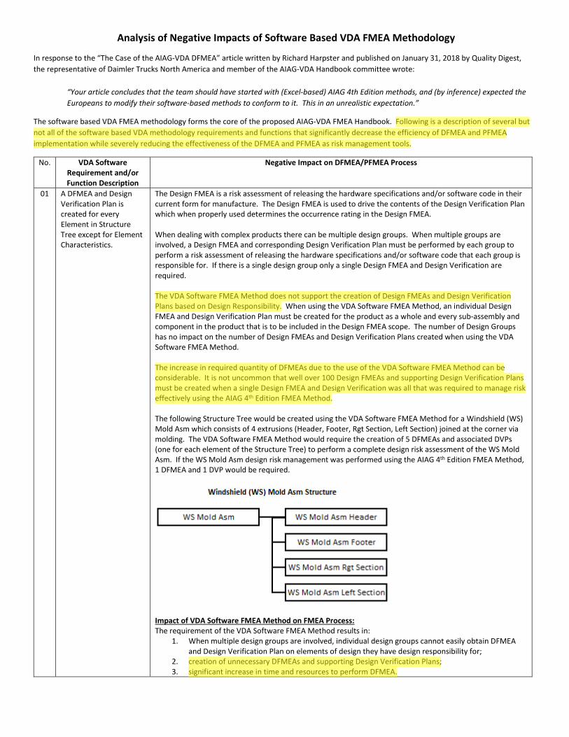
01 A DFMEA and Design Verification Plan is created for every Element in Structure Tree except for Element Characteristics.
The Design FMEA is a risk assessment of releasing the hardware specifications and/or software code in their current form for manufacture. The Design FMEA is used to drive the contents of the Design Verification Plan which when properly used determines the occurrence rating in the Design FMEA.
When dealing with complex products there can be multiple design groups. When multiple groups are involved, a Design FMEA and corresponding Design Verification Plan must be performed by each group to perform a risk assessment of releasing the hardware specifications and/or software code that each group is responsible for. If there is a single design group only a single Design FMEA and Design Verification are required.
The VDA Software FMEA Method does not support the creation of Design FMEAs and Design Verification Plans based on Design Responsibility. When using the VDA Software FMEA Method, an individual Design FMEA and Design Verification Plan must be created for the product as a whole and every sub-assembly and component in the product that is to be included in the Design FMEA scope. The number of Design Groups has no impact on the number of Design FMEAs and Design Verification Plans created when using the VDA Software FMEA Method.
The increase in required quantity of DFMEAs due to the use of the VDA Software FMEA Method can be considerable. It is not uncommon that well over 100 Design FMEAs and supporting Design Verification Plans must be created when a single Design FMEA and Design Verification was all that was required to manage risk effectively using the AIAG 4th Edition FMEA Method.
The following Structure Tree would be created using the VDA Software FMEA Method for a Windshield (WS) Mold Asm which consists of 4 extrusions (Header, Footer, Rgt Section, Left Section) joined at the corner via molding. The VDA Software FMEA Method would require the creation of 5 DFMEAs and associated DVPs (one for each element of the Structure Tree) to perform a complete design risk assessment of the WS Mold Asm. If the WS Mold Asm design risk management was performed using the AIAG 4th Edition FMEA Method, 1 DFMEA and 1 DVP would be required.
Impact of VDA Software FMEA Method on FMEA Process: The requirement of the VDA Software FMEA Method results in:
1. When multiple design groups are involved, individual design groups cannot easily obtain DFMEA and Design Verification Plan on elements of design they have design responsibility for;
2. creation of unnecessary DFMEAs and supporting Design Verification Plans; 3. significant increase in time and resources to perform DFMEA.
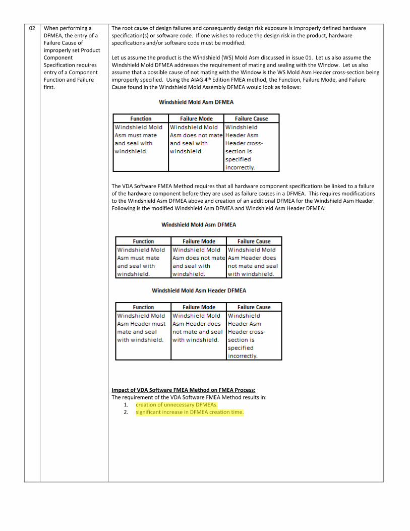
02 When performing a DFMEA, the entry of a Failure Cause of improperly set Product Component Specification requires entry of a Component Function and Failure first.
The root cause of design failures and consequently design risk exposure is improperly defined hardware specification(s) or software code. If one wishes to reduce the design risk in the product, hardware specifications and/or software code must be modified.
Let us assume the product is the Windshield (WS) Mold Asm discussed in issue 01. Let us also assume the Windshield Mold DFMEA addresses the requirement of mating and sealing with the Window. Let us also assume that a possible cause of not mating with the Window is the WS Mold Asm Header cross-section being improperly specified. Using the AIAG 4th Edition FMEA method, the Function, Failure Mode, and Failure Cause found in the Windshield Mold Assembly DFMEA would look as follows:
The VDA Software FMEA Method requires that all hardware component specifications be linked to a failure of the hardware component before they are used as failure causes in a DFMEA. This requires modifications to the Windshield Asm DFMEA above and creation of an additional DFMEA for the Windshield Asm Header. Following is the modified Windshield Asm DFMEA and Windshield Asm Header DFMEA:
Impact of VDA Software FMEA Method on FMEA Process: The requirement of the VDA Software FMEA Method results in:
1. creation of unnecessary DFMEAs. 2. significant increase in DFMEA creation time.
03 When performing a DFMEA, internally defined Functions/ Requirements must be defined for all Elements in the Structure Tree for a product.
The VDA Software FMEA Method requires that every product design requirement be decomposed to internally defined verifiable design function/requirements for every sub-assembly and component identified in the scope of the DFMEA that is involved in meeting the product level design function/requirement. The definition of product level design requirements to sub-assemblies and component level design requirements is not required to perform a proper design risk assessment.
The customer does not purchase the performance of the individual sub-assemblies and components. They purchase the performance of the product. Although a design engineer may develop a set of internal sub-assembly or component design requirements to aid in the design process, the engineer must never forget that the customer is purchasing the product design requirements. If a mistake is made in the translation of a product design requirement that the customer is purchasing to engineering defined internal design requirement(s), a product can be created where the sub-assemblies and components pass all the required design verification and the product fails to meet the customer’s product level design requirements.
The software based VDA DFMEA methodology has no method for detecting improperly defined internal design function/requirements or managing risk due to their incorrect definition. In thirty years of reviewing DFMEAs, the improper definition of product level function/design requirements was the most common mistake found. The software based VDA DFMEA method will expose companies to a geometric increase in this type of mistake.
The risk due to improper translation of customer design requirements to engineering internal sub-assembly and component design requirements cannot be overstated. There are many cases where the translation is extremely difficult. In other cases such as identifying all the chassis sub-assembly and component design requirements required to meet a customer chassis level design requirement such “Resonant Frequency of Chassis must be greater than 30 Hz”, the translation is impossible.
If the AIAG-VDA FMEA committee insists on using the current VDA FMEA Software Method, an additional level of “design requirement” risk assessment must be added for every sub-assembly and component identified in the scope of the DFMEA. A Design Validation Plan must be included in the risk assessment to determine the probability of customer exposure to harm due to improperly defined internal sub-assembly and component design requirements. The current VDA software in existence will have to be modified to support the additional risk assessment.
Even when done correctly, the required translation of product level design requirements to sub-assembly and component level design requirements is very often unnecessary. Why must an engineer be required to document that the function of a “Seal” is to seal or the function of a “Screw” is to attach to perform a design risk assessment? One of the biggest complaints engineers have about Design FMEAs is the time it takes to perform them.
Impact of VDA Software FMEA Method on FMEA Process: The requirement of the VDA Software FMEA Method results in:
1. increased customer risk exposure; 2. Increased company risk exposure; 3. significant increase in DFMEA creation time.
04 When performing a DFMEA, the Failure of the Element below the Focus Element is entered in the Failure Cause Column of the Focus Element DFMEA.
Unless the Element below the Focus Element is a Characteristic, this software based VDA methodology functionality results in an Element Failure Mode being entered as a Failure Cause in the DFMEA. This is a non-root cause of the Function Element Failure Mode. (Note: See Issue 2 above for example.) When a non-root cause is entered in the DFMEA, that line of the DFMEA cannot be used for risk management.
Impact of VDA Software FMEA Method on FMEA Process: The requirement of the VDA Software FMEA Method results in:
1. creation of DFMEAs that cannot be used to effectively manage design risk.
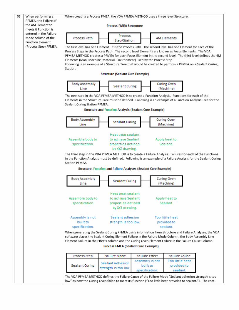
05 When performing a PFMEA, the Failure of the 4M Element to meets it Function is entered in the Failure Mode column of the Function Element (Process Step) PFMEA.
When creating a Process FMEA, the VDA PFMEA METHOD uses a three level Structure.
The first level has one Element. It is the Process Path. The second level has one Element for each of the Process Steps in the Process Path. The second level Elements are known as Focus Elements. The VDA PFMEA METHOD creates a PFMEA for each Focus Element in the second level. The third level defines the 4M Elements (Man, Machine, Material, Environment) used by the Process Step. Following is an example of a Structure Tree that would be created to perform a PFMEA on a Sealant Curing Station.
The next step in the VDA PFMEA METHOD is to create a Function Analysis. Functions for each of the Elements in the Structure Tree must be defined. Following is an example of a Function Analysis Tree for the Sealant Curing Station PFMEA.
The third step in the VDA PFMEA METHOD is to create a Failure Analysis. Failures for each of the Functions in the Function Analysis must be defined. Following is an example of a Failure Analysis for the Sealant Curing Station PFMEA.
When generating the Sealant Curing PFMEA using information from Structure and Failure Analyses, the VDA software places the Sealant Curing Element Failure in the Failure Mode Column, the Body Assembly Line Element Failure in the Effects column and the Curing Oven Element Failure in the Failure Cause Column.
The VDA PFMEA METHOD defines the Failure Cause of the Failure Mode “Sealant adhesion strength is too low” as how the Curing Oven failed to meet its function (“Too little heat provided to sealant.”). The root
cause of the Failure Mode “Sealing adhesion strength is too low” is not “how” but “why” the Curing Oven failed to meet its function. Example of root causes would be “Curing Oven Temperature Controller is out of calibration” and “Curing Oven Temperature Setting is set too low”. These are the root causes of “Too little heat provided to the sealant” and consequently the root causes of “Sealant adhesion strength is too low”.
Impact of VDA Software FMEA Method on FMEA Process: The requirement of the VDA Software FMEA Method results in:
1. creation of PFMEAs that cannot be used to effectively manage process risk; 2. creation of PFMEAs that cannot properly drive Process Control Plan creation.
The definition of root causes in the PFMEA is critical to the proper construction of the Process Control Plan. During the AIAG Software Summit, Mr. Cachat provided information from a 2018 study on IATF 16949 Audit Findings. He stated that “surprisingly Control Plans had 400 major findings and 6000 minor findings”. Why would the AIAG want to introduce a new PFMEA methodology that will severely increase the current major Control Plan problem?
06 When performing a PFMEA, the Failure of the Focus Element to meets it Function is entered in the Failure Mode column.
A process step can create objectionable conditions of the manufactured product that have nothing to do with the Function of the process step. These conditions can take on many forms including but not limited to contamination, material changes and dimensional changes. To capture these failures one would have to enter “negative functions” in the Function Analysis.
Impact of VDA Software FMEA Method on FMEA Process: The requirement of the VDA Software FMEA Method results in: Creation of PFMEAs that cannot capture all objectionable incidents that lead to risk exposure.
Copyright © 2018, Harpco® Systems Inc. All rights reserved.