Embed Size (px)
Citation preview
Modell der BR 91
55036
2
Informationen zum VorbildDie 1900 zum ersten Mal in Dienst gestellte preußische Tenderloko-motive der Baureihe T 93 bewies sehr schnell ihre guten Eigenschaf-ten. Daher ist es nicht verwunderlich, dass dieser Loktyp – teilweise in Lizenz – auch bei anderen Eisenbahnverwaltungen zu finden war. Ein Beispiel hierfür sind die 10 für die K.W.St.E. hergestellten Exemplare.
Die Lok war dank ihrer Höchstgeschwindigkeit von 65 km/h nicht nur im Güterzug- sondern auch im Personenzugverkehr auf Nebenbahn-strecken anzutreffen. Bei der DRG wurde die Lok unter der Bezeich-nung BR 913-18 eingereiht. Nach dem 2. Weltkrieg reduzierte sich die Anzahl der Fahrzeuge bei der Deutschen Bundesbahn rasch. 1964 wurde die letzte BR 91 ausgemustert. Zu spät stellten viele Eisen-bahnfreunde fest, dass eine der häufigsten gebauten Lokvarianten fast unbemerkt stetig aus dem Dienst geschieden war.
Information about the prototypeThe Prussian class T 93 tank locomotive was first placed into service in 1900 and quickly demonstrated its good qualities. For that reason it is not surprising that this type of locomotive was also used by other railroads – in part under license. An example of this is the group of 10 units built for the Royal Württemberg State Railways (K.W.St.E.).
Thanks to its maximum speed of 65 km/h (approximately 41 mph), this locomotive could be seen in use with passenger trains on branch lines as well as with freight trains. On the DRG the locomotive was redesignated as the class 913-18. After World War II the number of locomotives on the German Federal Railroad was quickly reduced. In 1964 the last class 91 was retired. Many railroad fans realised to late that a locomotive type built in the largest quantities was continually withdrawn from service unnoticed.
Informations concernant la locomotive réeleLa locomotive-tender prussienne de la série T 93, mise en service pour la première fois en 1900, démontra très rapidement ses capa-cités. Il n’est donc pas étonnant de retrouver ce type de machine – en partie sous licence – dans d’autres administrations ferrovi-aires. Un exemple réside dans les 10 exemplaires construits pour les Chemins de Fer Royaux Wurtembergeois.
Grâce à sa capacité d’atteindre une grande vitesse de 65 km/h, la locomotive se rencontrait non seulement en tête de trains de mar-chandises, mais aussi au crochet de trains de voyageurs sur les lignes régionales. A la DRG, la locomotive était répertoriée dans la série (BR) 913-18. Après la Seconde Guerre Mondiale, le nombre de machines décrut rapidement à la Deutsche Bundesbahn. La der-nière BR 91 fut radiée en 1964. Beaucoup d’amateurs ferroviaires constatèrent trop tard qu’une des séries les plus fabriquées avait été peu à peu écartée du service sans que celà ne ce remarque.
Informatie van het voorbeeldDe Pruisische tenderlocomotief, serie T 93 werd in 1900 voor het eerst in dienst gesteld en bewees al snel zijn goede eigenschappen. Daarom is het niet zo verwonderlijk dat dit locomotief type, voor een deel in licentie, ook bij andere spoorwegmaatschappijen te vinden was. Een voorbeeld hiervan zijn de 10 exemplaren die voor de K.W.St.E. gemaakt werden.
De loc was dankzij zijn maximum snelheid van 65 km/h niet alleen voor goederentreinen, maar ook voor personentreinen op neven banen te vinden. Bij de DRG werd de loc onder het type BR 913-18 opgenomen. Na de tweede wereldoorlog reduceerde het aantal locs bij de Deutsche Bundesbahn snel. In 1964 werd de laatste BR 91 buiten bedrijf gesteld. Te laat stelden vele spoorwegliefhebbers vast, dat één van de meest gebouwde locomotieven gestadig maar onopgemerkt buiten dienst gesteld was.
3
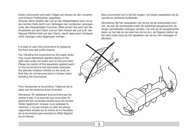
Diese Lokomotive wird beim Tragen am besten an den vorderen und hinteren Pufferbohlen angefasst. Hinweis: Beim Greifen der Lok an den Wasserkästen kann es an der rechten Seite leicht zum Verbiegen der montierten Leitungen unter den Wasserkästen kommen. Bitte achten Sie auch auf die Ansetzteile auf dem Dach und auf dem Kessel der Lok (z.B. das filigrane Pfeifenimitat auf dem Dach), damit diese beim Anfassen nicht verbogen oder abgerissen werden.
It is best to carry this locomotive by grasping the front and rear buffer beams.
Tip: Handling the locomotive by the water tanks may cause separately applied piping on the right side under the water tank to become bent. Please be careful of the separately applied parts on the locomotive‘s roof and boiler (example: the delicate imitation whistle on the roof), so that they do not become bent or broken when handling the locomotive.
Pour transporter la locomotive, l’idéal est de la saisir par les tampons avant et arrière.
Remarque: En saisissant la locomotive par les soutes à eau, il se pourrait que vous pliiez lé-gèrement les conduites situées sous les soutes. Veillez également, lorsque vous saisissez la machine, à ne pas rompre ou plier les pièces rapportées situées sur la toiture et la chaudière de la locomotive (par exemple le sifflet filigrané sur la toiture).
Deze locomotief kunt U bij het dragen, het beste vastpakken bij de voorste en achterste bufferbalk.
Opmerking: Bij het vastpakken van de loc bij de waterkasten kun-nen, de aan de rechterzijde onder de waterkast aangebrachte, lei-dingen gemakkelijk verbogen worden. Let ook op de aangebrachte delen op het dak en de ketel van de loc (b.v. de filigrane lokfluit op het dak) zodat deze bij het oppakken van de loc niet verbuigen of afbreken.
4
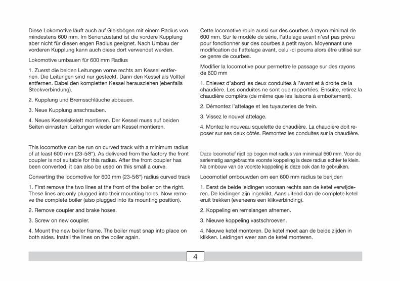
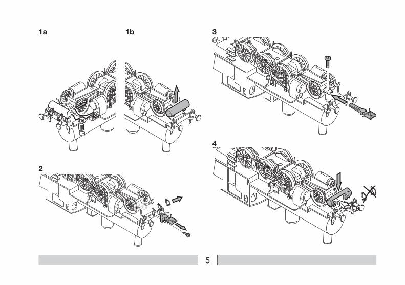
Diese Lokomotive läuft auch auf Gleisbögen mit einem Radius von mindestens 600 mm. Im Serienzustand ist die vordere Kupplung aber nicht für diesen engen Radius geeignet. Nach Umbau der vorderen Kupplung kann auch diese dort verwendet werden.
Lokomotive umbauen für 600 mm Radius
1. Zuerst die beiden Leitungen vorne rechts am Kessel entfer-nen. Die Leitungen sind nur gesteckt. Dann den Kessel als Vollteil entfernen. Dabei den kompletten Kessel herausziehen (ebenfalls Steckverbindung).
2. Kupplung und Bremsschläuche abbauen.
3. Neue Kupplung anschrauben.
4. Neues Kesselskelett montieren. Der Kessel muss auf beiden Seiten einrasten. Leitungen wieder am Kessel montieren.
This locomotive can be run on curved track with a minimum radius of at least 600 mm (23-5⁄8“). As delivered from the factory the front coupler is not suitable for this radius. After the front coupler has been converted, it can also be used on this small a curve.
Converting the locomotive for 600 mm (23-5⁄8“) radius curved track
1. First remove the two lines at the front of the boiler on the right. These lines are only plugged into their mounting holes. Now remo-ve the complete boiler (also plugged into its mounting position).
2. Remove coupler and brake hoses.
3. Screw on new coupler.
4. Mount the new boiler frame. The boiler must snap into place on both sides. Install the lines on the boiler again.
Cette locomotive roule aussi sur des courbes à rayon minimal de 600 mm. Sur le modèle de série, l’attelage avant n’est pas prévu pour fonctionner sur des courbes à petit rayon. Moyennant une modification de l’attelage avant, celui-ci pourra alors être utilisé sur ce genre de courbes.
Modifier la locomotive pour permettre le passage sur des rayons de 600 mm
1. Enlevez d’abord les deux conduites à l’avant et à droite de la chaudière. Les conduites ne sont que rapportées. Ensuite, retirez la chaudière complète (de même que les liaisons à emboîtement).
2. Démontez l’attelage et les tuyauteries de frein.
3. Vissez le nouvel attelage.
4. Montez le nouveau squelette de chaudière. La chaudière doit re-poser sur ses deux côtés. Remontez les conduites sur la chaudière.
Deze locomotief rijdt op bogen met radius van minimaal 660 mm. Voor de seriematig aangebrachte voorste koppeling is deze radius echter te klein. Na ombouw van de voorste koppeling is deze ook dan te gebruiken.
Locomotief ombouwden om een 600 mm radius te berijden
1. Eerst de beide leidingen vooraan rechts aan de ketel verwijde-ren. De leidingen zijn ingeklikt. Aansluitend dan de complete ketel eruit trekken (eveneens een klikverbinding).
2. Koppeling en remslangen afnemen.
3. Nieuwe koppeling vastschroeven.
4. Nieuwe ketel monteren. De ketel moet aan de beide zijden in klikken. Leidingen weer aan de ketel monteren.
5
1a 1b
2
4
3
6
FunktionDiese Lokomotive mit eingebauter Mehrzug-Elektronik bietet:
• Wahlweise Betrieb mit Gleichstrom (max ± 18 V=), Wechselstrom (Märklin Transformer 32 VA), Märklin Delta (nur Delta Station 6607), Märklin Digital (nur Control Unit) oder Märklin Systems (Mobile Station, Central Station). Ein Betrieb mit anderen Betriebssystemen (Impulsbreiten- steuerung, Central Control 1 etc.) ist nicht möglich.
• Die Betriebsart wird automatisch erkannt.• 80 Mehrzugadressen einstellbar. Adresse ab Werk: 09
• Mfx-Technologie für Mobile Station / Central Station. Name ab Werk: BR 91
• Veränderbare Anfahrverzögerung (ABV).• Veränderbare Bremsverzögerung (ABV).• Veränderbare Höchstgeschwindigkeit.
• Veränderbare Lautstärke der Geräusche• Einstellen der Lokparameter elektronisch über
Control Unit, Mobile Station oder Central Station.• Eingebaute Geräuschelektronik, nur im Betrieb mit
Control Unit oder Märklin Systems nutzbar. Zusätzliche schaltbare Geräusche.
• Eingebauter Rauchgenerator, im Märklin Systems-/Digital- Betrieb auch ausschaltbar.
• Das Modell ist für den Betrieb auf Märklin 1-Gleisen ent-wickelt. Ein Betrieb auf anderen Gleissystemen geschieht auf eigenes Risiko.
• Befahrbarer Mindestradius: 600 mm
• Modell besitzt hinten eine Telexkupplung, mit der im Digital-/Systemsbetrieb Märklin 1-Modelle mit Klauenkupp-lungen per Schaltbefehl abgekuppelt werden können. Bei Verwendung von Kupplungssystemen anderer Hersteller sind Betriebsprobleme nicht ausgeschlossen.
• Bis auf die Stirnbeleuchtung und dem Rauchgenerator sind die Funktionen in den Betriebsarten Gleichstrom, Wechselstrom und Märklin Delta ausgeschaltet.
Die bei normalem Betrieb anfallenden Wartungsarbeiten sind nachfolgend beschrieben. Für Reparaturen oder Ersatzteile wenden Sie sich bitte an Ihren Märklin-Fachhändler.
Jegliche Garantie-, Gewährleistungs- und Schadensersatzansprüche sind ausge-schlossen, wenn in Märklin-Produkten nicht von Märklin freigegebene Fremdteile eingebaut werden und / oder Märklin-Produkte umgebaut werden und die ein-gebauten Fremdteile bzw. der Umbau für sodann aufgetretene Mängel und/ oder Schäden ursächlich war. Die Darlegungs- und Beweislast dafür, dass der Einbau von Fremdteilen oder der Umbau in bzw. von Märklin-Produkten für aufgetretene Mängel und / oder Schäden nicht ursächlich war, trägt die für den Ein- und / oder Umbau verantwortliche Person und / oder Firma bzw. der Kunde.
Sicherheitshinweise• Die Lok darf nur mit einem dafür bestimmten Betriebs-
system (Gleichstrom, Märklin Wechselstrom-Transfor-mator 6647, Märklin Delta, Märklin Digital oder Märklin Systems) eingesetzt werden.
• Die Lok darf nur aus einer Leistungsquelle gleichzeitig versorgt werden.
• Beachten Sie unbedingt die Sicherheitshinweise in der Gebrauchsanleitung zu Ihrem Betriebssystem.
• Vorsicht: Egal ob das Modell steht oder fährt. Nie mit den Fingern in das Antriebsgestänge fassen. Es besteht Quetsch- und Verletzungsgefahr!

7
Schaltbare Funktionen
6647 6021STOP mobile station
systems
1 560652
central station 60212
f0 f0f8f8
Spitzensignal Dauernd ein function + off Licht-Taste Taste f0 mit Symbol
Rauchgenerator Dauernd ein f1 Taste 7 mit Symbol Taste f1 mit Symbol
Betriebsgeräusch — f2 Taste 3 mit Symbol Taste f2 mit Symbol
Geräusch: Lokpfeife — f3 Taste 4 mit Symbol Taste f3 mit Symbol
Telexkupplung — f4 Taste 6 mit Symbol Taste f4 mit Symbol
Geräusch: Bremsenquietschen aus — — Taste 8 mit Symbol Taste f5 mit Symbol
Geräusch: Kohle schaufeln — — Taste 5 mit Symbol Taste f6 mit Symbol
Geräusch: Glocke — — Taste 1 mit Symbol Taste f7 mit Symbol
ABV — — Taste 2 mit Symbol Taste f8 mit Symbol

8
FunctionThis locomotive has a built-in multi-train electronic circuit
and offers these features:• Optional operation with DC power (max. ± 18 volts DC),
AC power (with Märklin 32 VA transformer), with Märklin Delta (only with the 6607 Delta Station), Märklin Digital (only with the Control Unit), or Märklin Systems (Mobile Station, Central Station).
• The mode of operation is automatically recognized.• 80 multi-train addresses can be set. Address that set at
the factory: 09
• Mfx technology for the Mobile Station / Central Station. Name set at factory: BR 91
• Adjustable acceleration (ABV).• Adjustable Braking delay (ABV)• Adjustable maximum speed.
• Volume can be changed for the sound effects• Setting the locomotive parameters electronically with the
Control Unit, Mobile Station or Central Station.• Built-in sound effects circuit, can only be used in opera-
tion with the Control Unit or Märklin Systems. Additional sound effects that can be controlled.
• Built-in smoke generator, can also be turned off in Märklin Systems/Digital operation
• The model is designed for operation on Märklin 1 Gauge track. As the consumer you assume the risk for operating on other makes of track.
• Minimum radius for operation: 600 mm / 20-1/6“.
• The model has a Telex coupler at the end that can be un-coupled with a switching command from Märklin 1 Gauge models with claw couplers, when you are in digital/ sys-tems operation. You may have operations problems if you use other makes of couplers.
• Except for the headlights and the smoke generator, all of the functions are off in the modes of operation for DC power, AC power, and Märklin Delta.
Maintenance procedures that become necessary with normal operation of the locomotive are described below. Please see your authorized Märklin dealer for repairs or spare parts.
No warranty or damage claims shall be accepted in those cases where parts neit-her manufactured nor approved by Märklin have been installed in Märklin products or where Märklin products have been converted in such a way that the non-Märklin parts or the conversion were causal to the defects and / or damage arising. The burden of presenting evidence and the burden of proof thereof, that the installation of non-Märklin parts or the conversion in or of Märklin products was not causal to the defects and / or damage arising, is borne by the person and / or company responsible for the installation and / or conversion, or by the customer.
Safety Warnings• This locomotive is to be used only with an operating
system designed for it (Märklin 6646/6647 AC transformer, Märklin Delta, Märklin Digital or Märklin Systems).
• This locomotive must never be supplied with power from more than one transformer.
• Pay close attention to the safety warnings in the instructions for your operating system.
• Caution: Regardless of whether model is standing still or in motion, never grasp the drive rods and valve gear with your fingers. You may possibly pinch and injure your fingers!
9
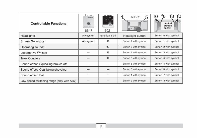
Controllable Functions
6647 6021STOP mobile station
systems
1 560652
central station 60212
f0 f0f8f8
Headlights Always on function + off Headlight button Button f0 with symbol
Smoke Generator Always on f1 Button 7 with symbol Button f1 with symbol
Operating sounds — f2 Button 3 with symbol Button f2 with symbol
Locomotive Whistle — f3 Button 4 with symbol Button f3 with symbol
Telex Couplers — f4 Button 6 with symbol Button f4 with symbol
Sound effect: Squealing brakes off — — Button 8 with symbol Button f5 with symbol
Sound effect: Coal being shoveled — — Button 5 with symbol Button f6 with symbol
Sound effect: Bell — — Button 1 with symbol Button f7 with symbol
Low speed switching range (only with ABV) — — Button 2 with symbol Button f8 with symbol

10
FonctionnementCette locomotive possède un équipement électronique pour con-duite multitrain:
• Au choix, exploitation conventionnelle avec courant continu (max ± 18 volts =), courant alternatif (Transformer 32 VA), ex-ploitation avec Märklin Delta (uniquement Delta Station 6607), Märklin Digital (uniquement Control Unit) ou Märklin Systems (Mobile Station ou Central Station). Une exploitation avec d’autres systèmes d’exploitation (courant à largeur d’impulsion variable, Central Control 1, etc.) n’est pas possible.
• Le mode d’exploitation est automatiquement détecté.
• Adresses disponibles: 01 – 80. Adresse encodée en usine: 09
• Technologie Mfx pour Mobile Station / Central Station. Nom en codee en usine: BR 91
• Temporisation d’accélération réglable (ABV).
• Temporisation de freinage réglable (ABV).
• Volume des bruitages réglable• Réglage des paramètres de la loco électroniquement à l’aide
de la Control Unit, de la Mobile Station ou de la Central Station.
• Bruiteur électronique intégré, utilisable uniquement lors d’exploitation avec la Control Unit ou Märklin Systems. Bruita-ges complémentaires commutables.
• Générateur fumigéne intégré, également commutable en exploitation avec Märklin Systems-/ Digital.
• Le modèle réduit est conçu pour rouler sur des voies Märklin 1. Le faire rouler sur des voies d’autres systèmes comporte des risques.
• Rayon minimal d’inscription en courbe: 600 mm.
• Le modèle est équipé d’attelages Telex grâce auxquels il est possible, en exploitation digital/ systems, de dételer à distance les modèles Märklin 1 dotés d’attelages à griffe. En cas d’utilisation d’un système provenant d’un autre fabricant, des problèmes sont susceptibles de survenir.
• A l’exception des feux de signalisation et le générateur fumi-géne, les fonctions sont désactivées en mode d’exploitation courant continu, courant alternatif et Märklin Delta.
Les travaux d‘entretien occasionnels à effectuer en exploitation or-male sont décrits plus loin. Pour toute réparation ou remplacement de pièces, adressez-vous à votre détaillant-spécialiste Märklin.
Tout recours à une garantie commerciale ou contractuelle ou à une demande de dommages-intérêt est exclu si des pièces non autorisées par Märklin sont inté-grées dans les produits Märklin et / ou si les produits Märklin sont transformés et que les pièces d’autres fabricants montées ou la transformation constituent la cause des défauts et / ou dommages apparus. C’est à la personne et / ou la société responsable du montage / de la transformation ou au client qu’incombe la charge de prouver que le montage des pièces d’autres fabricants sur des produits Märklin ou la transformation des produits Märklin n’est pas à l’origine des défauts et ou dommages apparus.
Remarques importantes sur la sécurité• La locomotive ne peut être mise en service qu’avec un système
d’exploitation adéquat (Märklin courant alternatif -transforma-teur 6647, Märklin Delta, Märklin Digital ou Märklin Systems).
• La locomotive ne peut être alimentée en courant que par une seule source de courant.
• Veuillez impérativement respecter les remarques sur la sécurité décrites dans le mode d’emploi en ce qui concerne le système d’exploitation.
• Attention : que le modèle soit arrêté ou qu‘il roule, ne jamais mettre les doigts dans le mécanisme d‘entraînement. Risque d‘écrasement et de blessure !
11
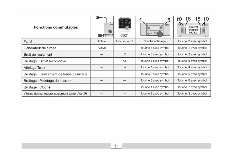
Fonctions commutables
6647 6021STOP mobile station
systems
1 5central station 60212
f0 f0f8f8
Fanal Activé function + off Touche éclairage Touche f0 avec symbol
Générateur de fumée Activé f1 Touche 7 avec symbol Touche f1 avec symbol
Bruit de roulement — f2 Touche 3 avec symbol Touche f2 avec symbol
Bruitage : Sifflet locomotive — f3 Touche 4 avec symbol Touche f3 avec symbol
Attelage Telex — f4 Touche 6 avec symbol Touche f4 avec symbol
Bruitage : Grincement de freins désactivé — — Touche 8 avec symbol Touche f5 avec symbol
Bruitage : Pelletage du charbon — — Touche 5 avec symbol Touche f6 avec symbol
Bruitage : Cloche — — Touche 1 avec symbol Touche f7 avec symbol
Vitesse de manœuvre (seulement temp. Acc./Fr — — Touche 2 avec symbol Touche f8 avec symbol
12
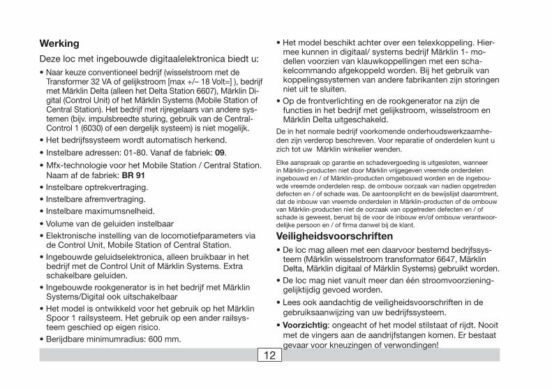
WerkingDeze loc met ingebouwde digitaalelektronica biedt u:• Naar keuze conventioneel bedrijf (wisselstroom met de
Transformer 32 VA of gelijkstroom [max +/– 18 Volt=] ), bedrijf met Märklin Delta (alleen het Delta Station 6607), Märklin Di-gital (Control Unit) of het Märklin Systems (Mobile Station of Central Station). Het bedrijf met rijregelaars van andere sys-temen (bijv. impulsbreedte sturing, gebruik van de Central-Control 1 (6030) of een dergelijk systeem) is niet mogelijk.
• Het bedrijfssysteem wordt automatisch herkend.
• Instelbare adressen: 01-80. Vanaf de fabriek: 09.
• Mfx-technologie voor het Mobile Station / Central Station. Naam af de fabriek: BR 91
• Instelbare optrekvertraging.• Instelbare afremvertraging.• Instelbare maximumsnelheid.
• Volume van de geluiden instelbaar• Elektronische instelling van de locomotiefparameters via
de Control Unit, Mobile Station of Central Station.• Ingebouwde geluidselektronica, alleen bruikbaar in het
bedrijf met de Control Unit of Märklin Systems. Extra schakelbare geluiden.
• Ingebouwde rookgenerator is in het bedrijf met Märklin Systems/Digital ook uitschakelbaar
• Het model is ontwikkeld voor het gebruik op het Märklin Spoor 1 railsysteem. Het gebruik op een ander railsys-teem geschied op eigen risico.
• Berijdbare minimumradius: 600 mm.
• Het model beschikt achter over een telexkoppeling. Hier-mee kunnen in digitaal/ systems bedrijf Märklin 1- mo-dellen voorzien van klauwkoppellingen met een scha-kelcommando afgekoppeld worden. Bij het gebruik van koppelingssystemen van andere fabrikanten zijn storingen niet uit te sluiten.
• Op de frontverlichting en de rookgenerator na zijn de functies in het bedrijf met gelijkstroom, wisselstroom en Märklin Delta uitgeschakeld.
De in het normale bedrijf voorkomende onderhoudswerkzaamhe-den zijn verderop beschreven. Voor reparatie of onderdelen kunt u zich tot uw Märklin winkelier wenden.
Elke aanspraak op garantie en schadevergoeding is uitgesloten, wanneer in Märklin-producten niet door Märklin vrijgegeven vreemde onderdelen ingebouwd en / of Märklin-producten omgebouwd worden en de ingebou-wde vreemde onderdelen resp. de ombouw oorzaak van nadien opgetreden defecten en / of schade was. De aantoonplicht en de bewijslijst daaromtrent, dat de inbouw van vreemde onderdelen in Märklin-producten of de ombouw van Märklin-producten niet de oorzaak van opgetreden defecten en / of schade is geweest, berust bij de voor de inbouw en/of ombouw verantwoor-delijke persoon en / of firma danwel bij de klant.
Veiligheidsvoorschriften• De loc mag alleen met een daarvoor bestemd bedrjfssys-
teem (Märklin wisselstroom transformator 6647, Märklin Delta, Märklin digitaal of Märklin Systems) gebruikt worden.
• De loc mag niet vanuit meer dan één stroomvoorziening-gelijktijdig gevoed worden.
• Lees ook aandachtig de veiligheidsvoorschriften in de gebruiksaanwijzing van uw bedrijfssysteem.
• Voorzichtig: ongeacht of het model stilstaat of rijdt. Nooit met de vingers aan de aandrijfstangen komen. Er bestaat gevaar voor kneuzingen of verwondingen!
13
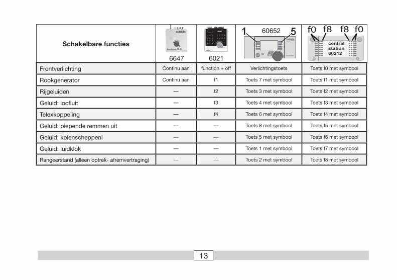
Schakelbare functies
6647 6021STOP mobile station
systems
1 560652
central station 60212
f0 f0f8f8
Frontverlichting Continu aan function + off Verlichtingstoets Toets f0 met symbool
Rookgenerator Continu aan f1 Toets 7 met symbool Toets f1 met symbool
Rijgeluiden — f2 Toets 3 met symbool Toets f2 met symbool
Geluid: locfluit — f3 Toets 4 met symbool Toets f3 met symbool
Telexkoppeling — f4 Toets 6 met symbool Toets f4 met symbool
Geluid: piepende remmen uit — — Toets 8 met symbool Toets f5 met symbool
Geluid: kolenscheppenl — — Toets 5 met symbool Toets f6 met symbool
Geluid: luidklok — — Toets 1 met symbool Toets f7 met symbool
Rangeerstand (alleen optrek- afremvertraging) — — Toets 2 met symbool Toets f8 met symbool
14
Fahren mit GleichstromGleichstrom-Fahrgeräte werden von Märklin für Spur-1-Modelle nicht angeboten. Geeignet sind Gleichstrom- Fahrgeräte aus dem Spielwarenbereich mit einer maximalen Spannung von ±18 Volt. Der Fahrtrichtungswechsel wird durch einen Polaritätswechsel vor-genommen. Die Bedienung des jeweiligen Fahrgerätes entnehmen Sie der Anleitung des Herstellers.
Hinweis: H0-Gleichstrom-Fahrgeräte geben eine maximale Span-nung von ±12 Volt ab. Die Lok erreicht jedoch ihre volle Leistungs-fähigkeit erst bei ±16 Volt. H0-Gleichspannungsfahrgeräte sind daher nur eingeschränkt verwendbar.
Im Betrieb mit Gleichstrom ist die fahrtrichtungsabhängige Beleuchtung eingeschaltet. Die Intensität der Beleuchtung ist geschwindigkeitsabhängig.
Von den Funktionen f1 bis f4 ist im Betrieb mit Gleichstrom die Funktion f1 (Rauchgenerator) immer eingeschaltet. Die restlichen Funktionen sind immer ausgeschaltet. Bei längerem Betrieb ohne Rauchöl empfehlen wir unbedingt den Rauchgenerator zu ent-fernen. Das Dampflokgeräusch kann im Gleichstrombetrieb nicht verwendet werden .
Operating the locomotive on direct currentDC power packs are not offered by Märklin for 1 Gauge models. Suitable DC power packs are those on the market that have a maximum voltage of ±18 volts. Direction reversing is done by reversing polarity. The manufacturer’s instructions for a particular make of power pack will give directions on how to use it to operate a locomotive.
Tip: H0 DC power packs supply a maximum voltage of ±12 volts. This locomotive reaches its full potential at ±16 volts. H0 DC power packs can therefore be used only with limitations.
The direction dependent headlights are turned on in operation with DC. The intensity of the headlights depends on the speed of the locomotive. During operation with DC, the f1 function (smoke generator) of the functions f1 to f4 is always turned on.
The other functions are always turned off. If you will be operating the locomotive for long periods of time without adding smoke fluid to the smoke generator, we strongly recommend removing the latter from the smoke stack. The steam locomotive sound effects cannot be used during operation with DC.

15
Fonctionnement en courant continuMärklin ne fournit pas de régulateurs à courant continu pour les modèles à l’échelle 1. Les régulateurs à courant continu que l’on peut trouver dans le commerce doivent délivrer une tension maxi-male de ±18 volts. Le changement du sens de la marche est réalisé gråce à un changement de polarité. Vous trouverez les instructions de commande relatives aux différents régulateurs de vitesse dans la notice du fabricant.
Indication: les régulateurs à courant continu H0 délivrent une tension maximale de ±12 volts. La locomotive n’atteint cependant sa pleine capacité qu’avec ±16 volt. Les régulateurs de vitesse H0 à tension continue ne peuvent donc être utilisés qu’avec certaines restrictions.
En exploitation à courant continu, l’éclairage en concordance avec le sens de la marche est enclenché. L’intensité de l’éclairage dépend de la vitesse.
Sur les 4 fonctions f1 à f4, la fonction f1 (générateur fumigène) est toujours enclenchée en mode d’exploitation à courant continu. Les fonctions restantes sont toujours désenclenchées. En cas d’utilisation prolongée sans liquide fumigène, nous vous recom-mandons fermement d’enlever le générateur fumigène. Le bruiteur de locomotive à vapeur ne peut pas être utilisé en exploitation à courant continu.
Rijden met gelijkstroomGelijkstroomrijregelaars voor spoor 1 worden door Märklin niet aangeboden. Gebruik hiervoor een gelijkstroomrijregelaar uit het speelgoedbereik met een maximale uitgangsspanning van onge-veer ±18 volt. De wisseling van de rijrichting wordt door ompolen bewerksstelligd. De bediening van uw arijregelaar leest u in de handleiding van de fabrikant.
Opmerking: H0-gelijkstroomregelaars geven een maximale span-ning van ±12 volt af. De lok bereikt zijn volle vermogen echter pas bij ±16 volt. H0-gelijkspanningsapparaten zijn daardoor slechts beperkt abruikbaar.
Bij het gelijkstroombedrijf is de rijrichtingsafhankelijke frontverlich-ting ingeschakeld. De helderheid van de verlichting is afhankelijk van de snelheid.
Van de extra functies f1 t/m f4 is, bij gebruik met gelijkstroom, de functie f1 (rookgenerator) altijd ingeschakeld. De andere functies zijn altijd uitgeschakeld. Als de loc lange tijd gebruikt wordt zonder rookvloeistof is het aan te bevelen de rookgenerator te verwijderen. Het stoomloc geluid kan bij het gelijk-stroombedrijf niet gebruikt worden.
16
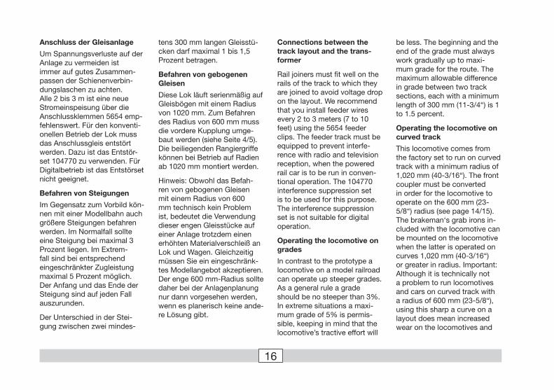
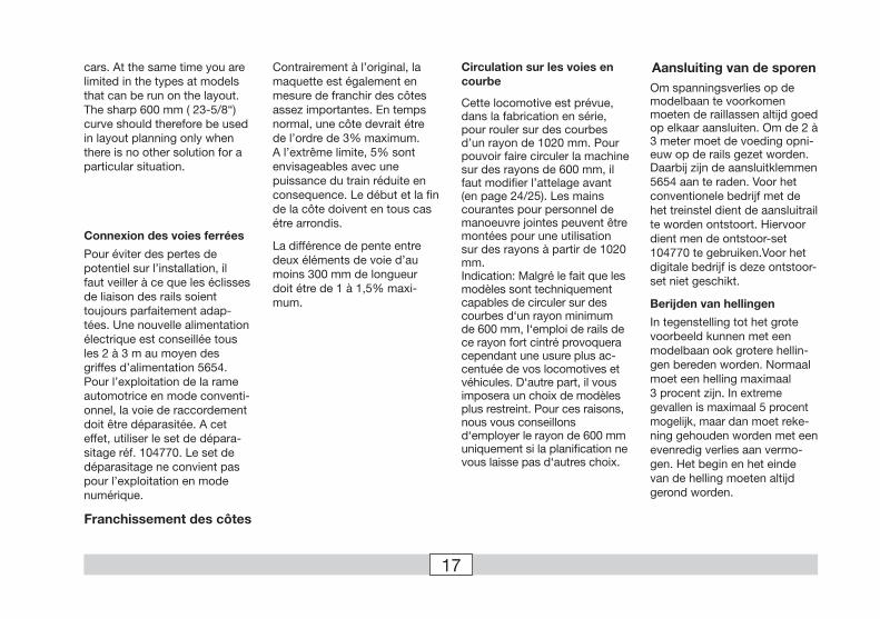
Anschluss der Gleisanlage
Um Spannungsverluste auf der Anlage zu vermeiden ist immer auf gutes Zusammen-passen der Schienenverbin-dungslaschen zu achten.Alle 2 bis 3 m ist eine neue Stromeinspeisung über die Anschlussklemmen 5654 emp-fehlenswert. Für den konventi-onellen Betrieb der Lok muss das Anschlussgleis entstört werden. Dazu ist das Entstör-set 104770 zu verwenden. Für Digitalbetrieb ist das Entstörset nicht geeignet.
Befahren von Steigungen
Im Gegensatz zum Vorbild kön-nen mit einer Modellbahn auch größere Steigungen befahren werden. Im Normalfall sollte eine Steigung bei maximal 3 Prozent liegen. Im Extrem-fall sind bei entsprechend eingeschränkter Zugleistung maximal 5 Prozent möglich. Der Anfang und das Ende der Steigung sind auf jeden Fall auszurunden.
Der Unterschied in der Stei-gung zwischen zwei mindes-
tens 300 mm langen Gleisstü-cken darf maximal 1 bis 1,5 Prozent betragen.
Befahren von gebogenen Gleisen
Diese Lok läuft serienmäßig auf Gleisbögen mit einem Radius von 1020 mm. Zum Befahren des Radius von 600 mm muss die vordere Kupplung umge-baut werden (siehe Seite 4/5). Die beiliegenden Rangiergriffe können bei Betrieb auf Radien ab 1020 mm montiert werden.
Hinweis: Obwohl das Befah-ren von gebogenen Gleisen mit einem Radius von 600 mm technisch kein Problem ist, bedeutet die Verwendung dieser engen Gleisstücke auf einer Anlage trotzdem einen erhöhten Materialverschleiß an Lok und Wagen. Gleichzeitig müssen Sie ein eingeschränk-tes Modellangebot akzeptieren. Der enge 600 mm-Radius sollte daher bei der Anlagenplanung nur dann vorgesehen werden, wenn es planerisch keine ande-re Lösung gibt.
Connections between the track layout and the trans-former
Rail joiners must fit well on the rails of the track to which they are joined to avoid voltage drop on the layout. We recommend that you install feeder wires every 2 to 3 meters (7 to 10 feet) using the 5654 feeder clips. The feeder track must be equipped to prevent interfe-rence with radio and television reception, when the powered rail car is to be run in conven-tional operation. The 104770 interference suppression set is to be used for this purpose.The interference suppression set is not suitable for digital operation.
Operating the locomotive on grades
In contrast to the prototype a locomotive on a model railroad can operate up steeper grades. As a general rule a grade should be no steeper than 3%. In extreme situations a maxi-mum grade of 5% is permis-sible, keeping in mind that the locomotive’s tractive effort will
be less. The beginning and the end of the grade must always work gradually up to maxi-mum grade for the route. The maximum allowable difference in grade between two track sections, each with a minimum length of 300 mm (11-3/4“) is 1 to 1.5 percent.
Operating the locomotive on curved track
This locomotive comes from the factory set to run on curved track with a minimum radius of 1,020 mm (40-3/16“). The front coupler must be converted in order for the locomotive to operate on the 600 mm (23-5/8“) radius (see page 14/15). The brakeman‘s grab irons in-cluded with the locomotive can be mounted on the locomotive when the latter is operated on curves 1,020 mm (40-3/16“) or greater in radius. Important: Although it is technically not a problem to run locomotives and cars on curved track with a radius of 600 mm (23-5/8“), using this sharp a curve on a layout does mean increased wear on the locomotives and
17
Aansluiting van de sporenOm spanningsverlies op de modelbaan te voorkomen moeten de raillassen altijd goed op elkaar aansluiten. Om de 2 à 3 meter moet de voeding opni-euw op de rails gezet worden. Daarbij zijn de aansluitklemmen 5654 aan te raden. Voor het conventionele bedrijf met de het treinstel dient de aansluitrail te worden ontstoort. Hiervoor dient men de ontstoor-set 104770 te gebruiken.Voor het digitale bedrijf is deze ontstoor-set niet geschikt.
Berijden van hellingen
In tegenstelling tot het grote voorbeeld kunnen met een modelbaan ook grotere hellin-gen bereden worden. Normaal moet een helling maximaal 3 procent zijn. In extreme gevallen is maximaal 5 procent mogelijk, maar dan moet reke-ning gehouden worden met een evenredig verlies aan vermo-gen. Het begin en het einde van de helling moeten altijd gerond worden.
cars. At the same time you are limited in the types at models that can be run on the layout. The sharp 600 mm ( 23-5/8“) curve should therefore be used in layout planning only when there is no other solution for a particular situation.
Connexion des voies ferrées
Pour éviter des pertes de potentiel sur l’installation, il faut veiller à ce que les éclisses de liaison des rails soient toujours parfaitement adap-tées. Une nouvelle alimentation électrique est conseillée tous les 2 à 3 m au moyen des griffes d’alimentation 5654. Pour l’exploitation de la rame automotrice en mode conventi-onnel, la voie de raccordement doit être déparasitée. A cet effet, utiliser le set de dépara-sitage réf. 104770. Le set de déparasitage ne convient pas pour l’exploitation en mode numérique.
Franchissement des côtes
Contrairement à l’original, la maquette est également en mesure de franchir des côtes assez importantes. En temps normal, une côte devrait étre de l’ordre de 3% maximum. A l’extrême limite, 5% sont envisageables avec une puissance du train réduite en consequence. Le début et la fin de la côte doivent en tous cas étre arrondis.
La différence de pente entre deux éléments de voie d’au moins 300 mm de longueur doit étre de 1 à 1,5% maxi-mum.
Circulation sur les voies en courbe
Cette locomotive est prévue, dans la fabrication en série, pour rouler sur des courbes d’un rayon de 1020 mm. Pour pouvoir faire circuler la machine sur des rayons de 600 mm, il faut modifier l’attelage avant (en page 24/25). Les mains courantes pour personnel de manoeuvre jointes peuvent être montées pour une utilisation sur des rayons à partir de 1020 mm. Indication: Malgré le fait que les modèles sont techniquement capables de circuler sur des courbes d‘un rayon minimum de 600 mm, I‘emploi de rails de ce rayon fort cintré provoquera cependant une usure plus ac-centuée de vos locomotives et véhicules. D‘autre part, il vous imposera un choix de modèles plus restreint. Pour ces raisons,nous vous conseillons d‘employer le rayon de 600 mm uniquement si la planification ne vous laisse pas d‘autres choix.

18
Lokparameter mit Control Unit ändern.Changing Locomotive Parameters with the Control Unit.
Modification des paramètres avec la Control Unit.Locparameter met de Control Unit.
Het verschil in de helling tussen twee tenminste 300 mm lange railstukken mag maximaal 1 à 1,5 procent bedragen.
Rijden in bogenDeze loc rijdt, af fabriek, op railbogen met een radius van 1020 mm. Voor het rijden door een boog met een radius van 600 mm moet de voorste kop-peling uitgebouwd worden (Zie pagina 34/35). De meegelever-de rangeerhandgrepen kunnen bij het gebruik van een radius van 1020 mm gemonteerd worden. Opmerking: Hoewel het berijden van gebogen rails met een radius van 600 mm technisch geen probleem is, betekend het gebruik van deze scherpe bogen in de baan een verhoogde slijtage aan lokomo-tieven en wagens. Tevens moet u rekening houden met een beperkte modellen keuze. De scherpe bogen met een radius van 600 mm dienen dan ook alleen in het sporenplan van u baan opgenomen te worden als er door plaatsgebrek geen an-dere oplossingen mogelijk zijn.
19
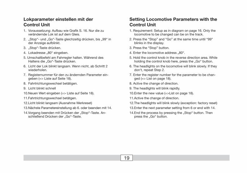
Lokparameter einstellen mit der Control Unit1. Voraussetzung: Aufbau wie Grafik S. 16. Nur die zu
verändernde Lok ist auf dem Gleis.
2. „Stop“- und „Go“-Taste gleichzeitig drücken, bis „99“ in der Anzeige aufblinkt.
3. „Stop“-Taste drücken.
4. Lokadresse „80“ eingeben.
5. Umschaltbefehl am Fahrregler halten. Während des Haltens die „Go“-Taste drücken.
6. Licht der Lok blinkt langsam. Wenn nicht, ab Schritt 2 wiederholen.
7. Registernummer für den zu ändernden Parameter ein-geben (=> Liste auf Seite 18).
8. Fahrtrichtungswechsel betätigen.
9. Licht blinkt schnell
10.Neuen Wert eingeben (=> Liste auf Seite 18).
11.Fahrtrichtungswechsel betätgen.
12.Licht blinkt langsam (Ausnahme Werkreset)
13.Nächste Parametereinstellung ab 6. oder beenden mit 14.
14.Vorgang beenden mit Drücken der „Stop“-Taste. An-schließend Drücken der „Go“-Taste.
Setting Locomotive Parameters with the Control Unit1. Requirement: Setup as in diagram on page 16. Only the
locomotive to be changed can be on the track.
2. Press the “Stop” and “Go” at the same time until “99” blinks in the display.
3. Press the “Stop” button.
4. Enter the locomotive address „80“.
5. Hold the control knob in the reverse direction area. While holding the control knob here, press the „Go“ button.
6. The headlights on the locomotive will blink slowly. If they don‘t, repeat Step 2.
7. Enter the register number for the parameter to be chan-ged (=> List on page 18).
8. Active the change of direction.
9. The headlights will blink rapidly.
10.Enter the new value (=>List on page 18).
11.Active the change of direction.
12.The headlights will blink slowly (exception: factory reset)
13.Enter the next parameter setting from 6 or end with 14.
14.End the process by pressing the „Stop“ button. Then press the „Go“ button.
20
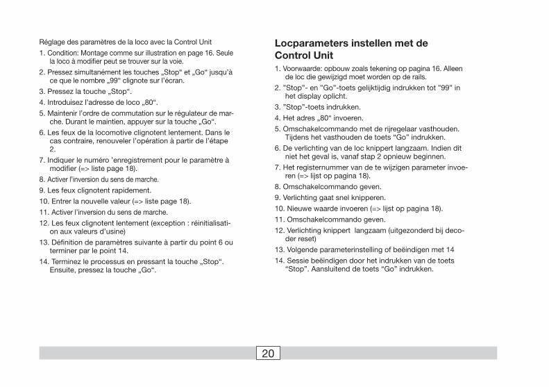
Réglage des paramètres de la loco avec la Control Unit
1. Condition: Montage comme sur illustration en page 16. Seule la loco à modifier peut se trouver sur la voie.
2. Pressez simultanément les touches „Stop“ et „Go“ jusqu’à ce que le nombre „99“ clignote sur l’écran.
3. Pressez la touche „Stop“.
4. Introduisez l’adresse de loco „80“.
5. Maintenir l’ordre de commutation sur le régulateur de mar-che. Durant le maintien, appuyer sur la touche „Go“.
6. Les feux de la locomotive clignotent lentement. Dans le cas contraire, renouveler l’opération à partir de l’étape 2.
7. Indiquer le numéro ’enregistrement pour le paramètre à modifier (=> liste page 18).
8. Activer l’inversion du sens de marche.
9. Les feux clignotent rapidement.
10. Entrer la nouvelle valeur (=> liste page 18).
11. Activer l’inversion du sens de marche.
12. Les feux clignotent lentement (exception : réinitialisati-on aux valeurs d’usine)
13. Définition de paramètres suivante à partir du point 6 ou terminer par le point 14.
14. Terminez le processus en pressant la touche „Stop“. Ensuite, pressez la touche „Go“.
Locparameters instellen met de Control Unit1. Voorwaarde: opbouw zoals tekening op pagina 16. Alleen
de loc die gewijzigd moet worden op de rails.
2. ”Stop”- en ”Go”-toets gelijktijdig indrukken tot ”99” in het display oplicht.
3. ”Stop”-toets indrukken.
4. Het adres „80“ invoeren.
5. Omschakelcommando met de rijregelaar vasthouden. Tijdens het vasthouden de toets “Go” indrukken.
6. De verlichting van de loc knippert langzaam. Indien dit niet het geval is, vanaf stap 2 opnieuw beginnen.
7. Het registernummer van de te wijzigen parameter invoe-ren (=> lijst op pagina 18).
8. Omschakelcommando geven.
9. Verlichting gaat snel knipperen.
10. Nieuwe waarde invoeren (=> lijst op pagina 18).
11. Omschakelcommando geven.
12. Verlichting knippert langzaam (uitgezonderd bij deco-der reset)
13. Volgende parameterinstelling of beëindigen met 14
14. Sessie beëindigen door het indrukken van de toets “Stop”. Aansluitend de toets “Go” indrukken.

21
1
80
1
Lokparameter ändern mit der Control Unit 6021.
Changing Locomotive Parameters with the 6021 Control Unit.
Modification des paramètres de la locomotive avec la Control Unit 6021.
Locparameter wijzigen met de Control Unit.
1
1
99
1
2
80
2
1
01
� � � �
�
01
1
1
2
10
10
1
� � � 11
�
14
12
22
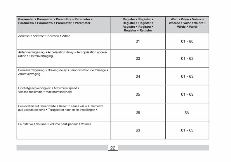
Parameter • Parameter • Paramètre • Parameter • Parámetro • Parametro • Parameter • Parameter
Register • Register • Registre • Register • Registro • Registro • Register • Register
Wert • Value • Valeur • Waarde • Valor • Valore •
Värde • Værdi
Adresse • Address • Adresse • Adres
01 01 - 80
Anfahrverzögerung • Acceleration delay • Temoprisation accélé-ration • Optrekvertraging
03 01 - 63
Bremsverzögerung • Braking delay • Temporisation de freinage • Afremvertraging
04 01 - 63
Höchstgeschwindigkeit • Maximum speed • Vitesse maximale • Maximumsneilheid
05 01 - 63
Rückstellen auf Serienwerte • Reset to series value • Remettre aux valeurs de série • Terugzetten naar serie-instellingen •
08 08
Lautstärke • Volume • Volume haut-parleur • Volume
63 01 - 63
23
Betrieb mit Mobile Station / Central Station
• Lok aufgleisen. Die Lok meldet sich selbsttätig in der Lokliste an.
• Keine Rückmeldung der Lok, wenn: bei Mobile Station der Geschwindigkeitsbalken blinkt bei Central Station das mfx-Symbol unterstrichen ist
• Lok abmelden: 1. Lok vom Gleis entfernen. 2. Lokeintrag löschen. Eine Adressänderung ist nicht notwendig.
Lokparameter mit der Mobile Station / Central Station verändern
1. Lok aus der Lokliste auswählen.
2. Zum Untermenü „LOKÄNDERN“ wechseln.
3. Zum Untermenü „VMAX“ (Höchstgeschwindigkeit), „ACC“ (Beschleunigung), „DEC“ (Bremsen), „VOL“ (Lautstärke) oder „RESET“ (Decoder auf Werkeinstellung zurück) wechseln.
4. Neuen Wert eingeben und übernehmen.Beachten Sie die Hinweise in der Anleitung zur Mobile Station / Central Station.
Operation with the Mobile Station / Central Station
• Set the locomotive on the track. The locomotive automati-cally registers itself in the locomotive list.
• The locomotive will not communicate back to the control-ler when: the speed bar on the Mobile Station blinks. the mfx symbol has a line beneath it on the Central Station.
• Taking the locomotive out of the locomotive list: 1. Remove the locomotive from the track. 2. Delete the locomotive entry. It is not necessary to change the address.
Changing Locomotive Parameters with the Mobile Station / Central Station
1. Select the locomotive from the locomotive list.
2. Change to the submenu “EDIT LOC”.
3. Go to the submenu „VMAX“ (maximum speed), „ACC“ (acceleration), „DEC“ (brakes), „VOL“ (volume) or „RESET“ (resetting the decoder to factory default settings).
4. Enter the new value and accept it into the system.Please note the information in the instructions for the Mobile Stati-on / Central Station.
24
Exploitation avec Mobile Station / Central Station
• Enrailler la locomotive. La locomotive signale automati-quement sa présence dans la liste des locos.
• Pas de rétrosignalisation de la locomotive lorsque : - la barre de vitesse clignote pour Mobile Station - le symbole mfx est souligné pour Central Station
• Appeler loco: 1. Enlever loco de la voie. 2. Effacer entrée loco. Une modification de l’adresse n’est pas nécessaire.
Modification des paramètres de la loco avec la Mobile Station/Central Station
1. Sélectionnez la loco dans la liste.
2. Allez au sous-menu „MODIF LOC“.
3. Ouvrir le sous-menu « VMAX » (vitesse maximale), « ACC » (accélération), « DEC » (freinage), « VOL » (volume) ou « RESET » (réinitialisation du décodeur aux valeurs d’usine).
4. Entrez la nouvelle valeur et acceptez.Respectez les remarques mentionnées dans l’instruction accompa-gnant la Mobile Station / Central Station.
Bedrijf met Mobile Station / Central Station
• Loc op de rails plaatsen. De loc meldt zichzelf aan in de loclijst.
• Geen terugmelding van de loc als: bij het Mobile Station de snelheidsbalk knippert bij het Central Station het mfx-symbool onderstreept is
• Loc afmelden: 1. loc van de rails nemen 2. loc invoer wissen. Het wijzigen van het adres is niet nodig.
Locparameter wijzigen met het Mobile Station/Central Station
1. Loc uit de loclijst kiezen.
2. Ga naar het nevenmenu ”WIJZIG LOC”.
3. Naar het nevenmenu “VMAX” (maximumsnelheid) “ACC” (optrekken), “DEC” (afremmen), “VOL” (volume) of “RESET” (decoder terugzetten naar fabrieksinstelling) omschakelen.
4. Nieuwe waarde invoeren en overnemen.Lees ook de opmerkingen in de gebruiksaanwijzing van het Mobile Station / Central Station.
25
Pflegehinweis
Diese Lok kann auch im Außenbereich eingesetzt werden. Ein Betrieb bei schlechten Witterungsbe-dingungen (Schnee oder Regen) wird nicht empfoh-len.
Antrieb und Elektronik sind gegen Spritzwasser geschützt. Wasserdurch-fahrten sind nicht möglich.
Es wird empfohlen, das Modell nach dem Betrieb im Außenbereich auf Ver-schmutzung zu prüfen und gegebenenfalls trocken mit Staubtuch oder Pinsel zu reinigen. Nie die Lok unter fließendem Wasser reinigen.
Hinweis: Reinigungsmit-tel können die Farbgebung oder die Beschriftung der Lok angreifen und beschä-digen.
Remarque sur l’entretien
Cette locomotive peut également être mise en service à l’air libre. Une uti-lisation par mauvais temps (neige ou pluie) n’est pas recommandée.
Le moteur et l’électro-nique sont protégés contre les projections d’eau. Des trajets dans l’eau ne sont pas possibles.
Il est recommandé de vérifier l’encrassement du modèle après une utilisa-tion à l’extérieur et, le cas échéant, de nettoyer le modèle à l’aide d’un chiffon doux ou un pinceau. Ne jamais nettoyer le modèle au jet d’eau.
Attention: Certains sol-vants et produits d’entretien peuvent altérer le marquage et la peinture du modèle.
Tips For The Care Of Your Locomotive
This locomotive can also be used outdoors. We do not recommend running the locomotive in bad weather (snow or rain).
The mechanism and the electronic circuit are protec-ted against spraying water. The locomotive cannot be run through water.
We recommend that you check the locomotive over after running in outdoors and that you dry it with a cloth or clean in with a brush if necessary. Never clean the locomotive with running water.
Important: Cleaning flu-ids can attack the finish and lettering for the locomotive and damage them.
Opmerkingen voor het onderhoud
Deze loc kan ook buiten gebruikt worden. Het gebruik bij slecht weer (sneeuw of regen) is niet aan te raden.
Aandrijving en elektro-nica zijn weliswaar afge-schermd tegen spatwater maar rijden door het water is niet mogelijk.
Het is aan te bevelen het model na het gebruik buiten te controleren op vuil en dit eventueel droog te verwij-deren met een stofdoek of een zachte kwast. Nooit de loc onder stromend water reinigen.
Opmerking: reinigings-middelen kunnen de lak en de opschriften op de loc aantasten en beschadigen.
26
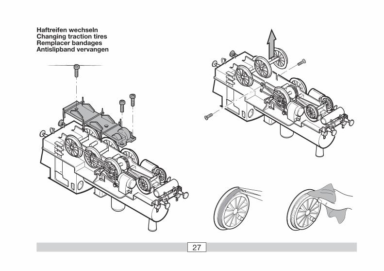
Haftreifen wechseln• Wir empfehlen das Modell in das Styroporoberteil der
Verpackung zu legen.
• Entfernen Sie die Laufwerkabdeckung unten
• Entfernen Sie das Gestänge rechts und links
• Radsatz herausnehmen
Changing traction tires• We recommend laying the model in the upper styrofoam
part of the packaging.
• Remove the running gear cover below
• Remove the right and left valve gear
• Remove the wheel set
Remplacement des bandages d’adhérence• Nous recommandons de déposer le modèle dans la partie
supérieure en styropor de l’emballage.
• Enlevez le couvercle inférieur de protection des engrenages
• Enlevez les mouvements (distribution et embiellage) gau-che et droit
• Retirez les essieux
Antislip banden vervangen• Wij raden u aan het model in het tempex bovendeel van
de verpakking te leggen.
• Verwijder de drijfwerkafdekking aan de onderzijde
• Verwijder de schuifbeweging links en rechts
• Neem de wielas er uit
27
Haftreifen wechselnChanging traction tiresRemplacer bandagesAntislipband vervangen
28
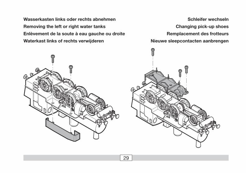
Stromschleifer wechseln• Wasserkasten links entfernen.
• Wir empfehlen das Modell in das Styroporoberteil der Verpackung zu legen.
• Entfernen Sie die Laufwerkabdeckung unten. Radsatz herausnehmen
• Alten Stromabnehmer nach aussen drücken
• Verbindungskabel auf der Platine lösen
• Neuen Stromabnehmer einstecken und anschliessen
Changing electrical pickups• Remove the water tank on the left.
• We recommend laying the model in the upper styrofoam part of the packaging.
• Remove the running gear cover below. Remove the wheel set
• Press the old electrical pickup away from the locomotive
• Loosen the connecting wire on the circuit board
• Insert the new electrical pickup and connect it to the circuit board
Remplacement du / des patin(s) de prise de courant• Enlevez la soute à eau gauche.
• Nous recommandons de déposer le modèle dans la partie supérieure en styropor de l’emballage.
• Enlevez le couvercle inférieur de protection des engrena-ges. Retirez les essieux
• Poussez le vieux patin hors de son logement
• Détachez le câble de raccordement à la platine
• Insérez le nouveau patin et raccordez-le
Wiel sleepcontact vervangen• Waterkast aan de linker kant verwijderen.
• Wij raden u aan het model in het tempex bovendeel van de verpakking te leggen.
• Verwijder de drijfwerkafdekking aan de onderzijde. Neem de wielas er uit
• Oude sleepcontact naar buiten drukken
• Verbindingsdraad op de print verwijderen
• Nieuw sleepcontact insteken en aansluiten
29
Schleifer wechseln
Changing pick-up shoes
Remplacement des frotteurs
Nieuwe sleepcontacten aanbrengen
Wasserkasten links oder rechts abnehmen
Removing the left or right water tanks
Enlèvement de la soute à eau gauche ou droite
Waterkast links of rechts verwijderen
30
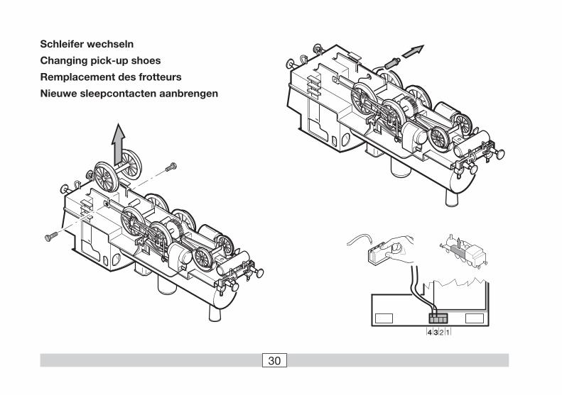
Schleifer wechseln
Changing pick-up shoes
Remplacement des frotteurs
Nieuwe sleepcontacten aanbrengen
4 3 2 1
31
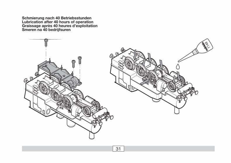
Schmierung nach 40 BetriebsstundenLubrication after 40 hours of operationGraissage après 40 heures d’exploitationSmeren na 40 bedrijfsuren
7149

32
Rauchpatrone wechseln• Linken Wasserkasten entfernen
• Anschlüsse des Rauchgenerators entfernen
• Vordere Rauchkammertür entfernen (Steckverbindung)
• Rauchgenerator nach oben rausdrücken
• Aufsatz vom alten Rauchgenerator abziehen und auf den neuen Rauchgenerator stecken
Vorsicht: Bei eingeschaltetem Rauchgenerator nie den Schorn-stein berühren oder von oben in den Schornstein fassen. Verbrennungsgefahr! Ein Betrieb der Lok mit eingeschaltetem Rauchgenerator von Kindern ist daher nicht zulässig.
Changing the smoke generator• Remove the left water tank
• Remove the connections to the smoke generator
• Remove the front smokebox door (plug-in connection)
• Press the smoke generator up and out of the smoke stack
• Pull off the cap from the old smoke generator and install on the new smoke generator
Caution: Never touch the smoke stack or grasp the smoke stack from above, when the smoke generator is turned on. You may possibly burn yourself! For this reason, this locomotive should not be operated by children, when the smoke generator is turned on.
4 3 2 1
33
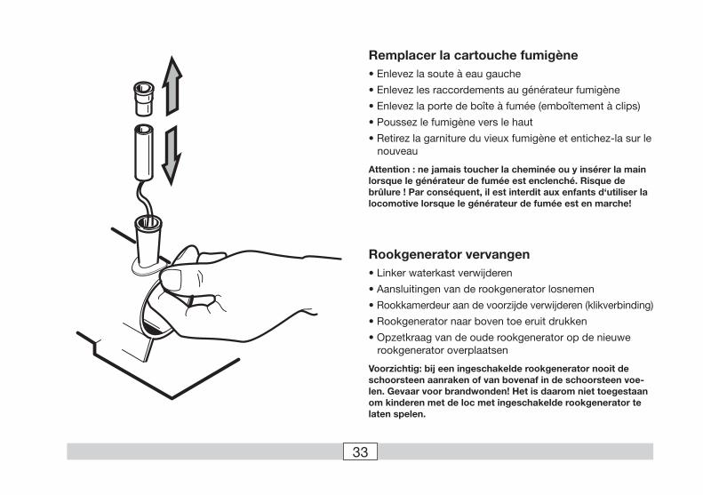
Remplacer la cartouche fumigène• Enlevez la soute à eau gauche
• Enlevez les raccordements au générateur fumigène
• Enlevez la porte de boîte à fumée (emboîtement à clips)
• Poussez le fumigène vers le haut
• Retirez la garniture du vieux fumigène et entichez-la sur le nouveau
Attention : ne jamais toucher la cheminée ou y insérer la main lorsque le générateur de fumée est enclenché. Risque de brûlure ! Par conséquent, il est interdit aux enfants d‘utiliser la locomotive lorsque le générateur de fumée est en marche!
Rookgenerator vervangen• Linker waterkast verwijderen
• Aansluitingen van de rookgenerator losnemen
• Rookkamerdeur aan de voorzijde verwijderen (klikverbinding)
• Rookgenerator naar boven toe eruit drukken
• Opzetkraag van de oude rookgenerator op de nieuwe rookgenerator overplaatsen
Voorzichtig: bij een ingeschakelde rookgenerator nooit de schoorsteen aanraken of van bovenaf in de schoorsteen voe-len. Gevaar voor brandwonden! Het is daarom niet toegestaan om kinderen met de loc met ingeschakelde rookgenerator te laten spelen.

34
7310
2 6 348 1 5
9 10 14 13 11 26 19
16
17
88 8721 20
22 2324
76
76
74
75
76
74
77
73
71
72 61
57
81
79
33
78
80
80
17 62
63
81 31
32
29
30
38
43
40 42
46 48
49 52
50
39
41
40 47
59
48 49
55
55 58
56
53
45
44
45
66
60
8682
83
84
65
63
85
69 70
64
37
34 3
5 36
27
68
67 46
48
49
80
47
15
4948
55
59 58 5654
52 51
127
28
2518
Det
ails
der
Dar
stel
lung
kön
nen
von
dem
Mod
ell a
bw
eich
en
35
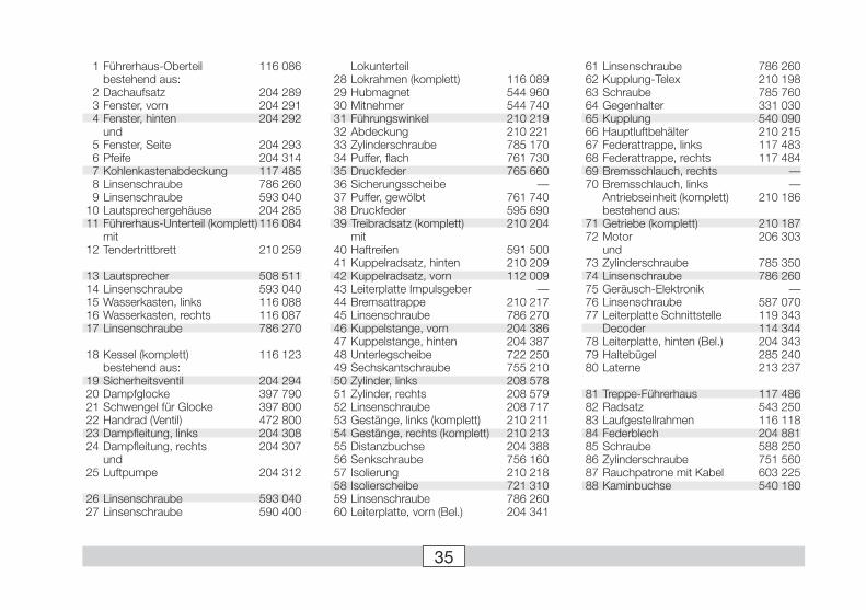
1 Führerhaus-Oberteil 116 086 bestehend aus: 2 Dachaufsatz 204 289 3 Fenster, vorn 204 291 4 Fenster, hinten 204 292 und 5 Fenster, Seite 204 293 6 Pfeife 204 314 7 Kohlenkastenabdeckung 117 485 8 Linsenschraube 786 260 9 Linsenschraube 593 040 10 Lautsprechergehäuse 204 285 11 Führerhaus-Unterteil (komplett) 116 084 mit 12 Tendertrittbrett 210 259
13 Lautsprecher 508 511 14 Linsenschraube 593 040 15 Wasserkasten, links 116 088 16 Wasserkasten, rechts 116 087 17 Linsenschraube 786 270
18 Kessel (komplett) 116 123 bestehend aus: 19 Sicherheitsventil 204 294 20 Dampfglocke 397 790 21 Schwengel für Glocke 397 800 22 Handrad (Ventil) 472 800 23 Dampfleitung, links 204 308 24 Dampfleitung, rechts 204 307 und 25 Luftpumpe 204 312
26 Linsenschraube 593 040 27 Linsenschraube 590 400
61 Linsenschraube 786 260 62 Kupplung-Telex 210 198 63 Schraube 785 760 64 Gegenhalter 331 030 65 Kupplung 540 090 66 Hauptluftbehälter 210 215 67 Federattrappe, links 117 483 68 Federattrappe, rechts 117 484 69 Bremsschlauch, rechts — 70 Bremsschlauch, links — Antriebseinheit (komplett) 210 186 bestehend aus: 71 Getriebe (komplett) 210 187 72 Motor 206 303 und 73 Zylinderschraube 785 350 74 Linsenschraube 786 260 75 Geräusch-Elektronik — 76 Linsenschraube 587 070 77 Leiterplatte Schnittstelle 119 343 Decoder 114 344 78 Leiterplatte, hinten (Bel.) 204 343 79 Haltebügel 285 240 80 Laterne 213 237
81 Treppe-Führerhaus 117 486 82 Radsatz 543 250 83 Laufgestellrahmen 116 118 84 Federblech 204 881 85 Schraube 588 250 86 Zylinderschraube 751 560 87 Rauchpatrone mit Kabel 603 225 88 Kaminbuchse 540 180
Lokunterteil 28 Lokrahmen (komplett) 116 089 29 Hubmagnet 544 960 30 Mitnehmer 544 740 31 Führungswinkel 210 219 32 Abdeckung 210 221 33 Zylinderschraube 785 170 34 Puffer, flach 761 730 35 Druckfeder 765 660 36 Sicherungsscheibe — 37 Puffer, gewölbt 761 740 38 Druckfeder 595 690 39 Treibradsatz (komplett) 210 204 mit 40 Haftreifen 591 500 41 Kuppelradsatz, hinten 210 209 42 Kuppelradsatz, vorn 112 009 43 Leiterplatte Impulsgeber — 44 Bremsattrappe 210 217 45 Linsenschraube 786 270 46 Kuppelstange, vorn 204 386 47 Kuppelstange, hinten 204 387 48 Unterlegscheibe 722 250 49 Sechskantschraube 755 210 50 Zylinder, links 208 578 51 Zylinder, rechts 208 579 52 Linsenschraube 208 717 53 Gestänge, links (komplett) 210 211 54 Gestänge, rechts (komplett) 210 213 55 Distanzbuchse 204 388 56 Senkschraube 756 160 57 Isolierung 210 218 58 Isolierscheibe 721 310 59 Linsenschraube 786 260 60 Leiterplatte, vorn (Bel.) 204 341

This device complies with Part 15 of the FCC Rules.Operation is subject to the following two conditions:(1) This device may not cause harmful interference, and(2) this device must accept any interference received, including interference that may cause undesired operation.
Gebr. Märklin & Cie. GmbHPostfach 8 60D-73008 Göppingenwww.maerklin.com
Änderungen vorbehalten© by Gebr. Märklin & Cie GmbH
117488 03 07 Ni Ef