Embed Size (px)
Citation preview
a Corresponding author: [email protected] or [email protected]
Modernised DC traction substation recuperating energy of braking
Piotr Drozdowski1,a and Arkadiusz Duda2 1Cracow Univ. of Tech., Institute on Electromech. Energy Conv. Warszawska 24, 31-155 Kraków, Poland 2Cracow Univ. of Tech., Institute on Electromech. Energy Conv. Warszawska 24, 31-155 Kraków, Poland
Abstract. The traction substation composed of the 3-phase transformer and the output diode rectifier is still the fundamental device for DC traction supply. In this paper two technical solutions (power electronic converters) allowing for braking energy recuperation to the AC mains are discussed. This has been thought as the modernisation of the existing traction substations allowing for high speed trains regenerative braking and braking of heavy train hollers. Such a solution brings some profits: energy recuperation, mechanical brakes saving and enhanced quality of traction vehicle control. For the proposed converters technical and economical advantages and drawbacks are indicated.
1 Introduction In the last time the DC traction vehicles are driven with cage induction motors supplied by VS inverters. These are the heavy train hollers and the hollers for trains of high speed. For braking of both the trains a high energy dissipation is demanded. The vehicles are supplied with the traction substations composed of transformer and diode rectifier. The transformer is supplied from high voltage mains giving at the output the low voltage appropriate for the DC output of the rectifier (3 kV DC voltage for railway traction, 0.6 kV DC voltage for urban transportation and additionally 750V and 1.5 kV). Such a supply does not allow for energy recuperation during regenerative braking of the vehicles. The braking energy can be dissipated only for the need of other vehicles or, in case of lack of such vehicles, the dynamic braking with braking resistors can be performed. Electrical braking is usually supported by the mechanical. For some traction vehicles without electric braking the mechanical braking is the only possibility. The braking energy amounts to about 10 to 30 % of the whole vehicle energy depending mainly on the kind of traction, the time-table of trains, the railway line profile and some others [5]. So, the energy recuperation to the AC mains could be considered as profitable according to the amount of this energy, mechanical brakes saving and flexible control of the vehicle drive.
The solution for bidirectional power flow from AC mains to the DC side and vice versa is well known in the power electronics by employing two back-to-back line-frequency converters. One solution assuring such a power flow is the voltage source inverter (VSI) that is in fact the parallel connection of the line frequency converter (feedback diodes) and the 3-phase bridge of full
controlled semiconductor switches (GTO, IGCT, IGBT) – Fig. 1. Another proposed bridge composed of SCRs instead of the mentioned turn off power electronic switches must be supplemented with two additional cut-off thyristors (GTO or SCR) – Fig. 3. Both the 3-phase bridges must be controlled with respect to the supplying AC voltages. So, these are in fact the line-frequency converters.
The researches of the modernised traction substations were performed for a low power model to indicate if the real system seem to be promising. The substations were loaded by the drive with the input pulse converter. This could be a vector controlled VSI asynchronous drive or a DC motor drive with the supplying chopper. Both the proposed installations that could supplement the existing traction substations are compared in the conclusions.
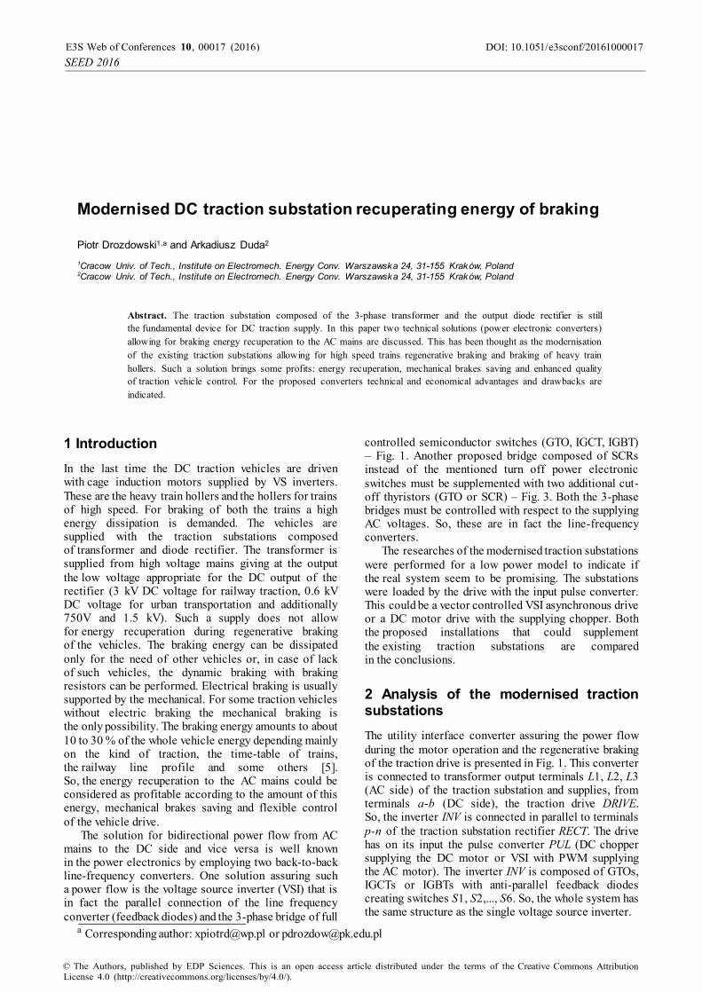
2 Analysis of the modernised traction substations The utility interface converter assuring the power flow during the motor operation and the regenerative braking of the traction drive is presented in Fig. 1. This converter is connected to transformer output terminals L1, L2, L3 (AC side) of the traction substation and supplies, from terminals a-b (DC side), the traction drive DRIVE. So, the inverter INV is connected in parallel to terminals p-n of the traction substation rectifier RECT. The drive has on its input the pulse converter PUL (DC chopper supplying the DC motor or VSI with PWM supplying the AC motor). The inverter INV is composed of GTOs, IGCTs or IGBTs with anti-parallel feedback diodes creating switches S1, S2,..., S6. So, the whole system has the same structure as the single voltage source inverter.
DOI: 10.1051/
2016,10 1000017e3sconf/2016E3S Web of Conferences
SEED
00017 (2016)
© The Authors, published by EDP Sciences. This is an open access article distributed under the terms of the Creative Commons Attribution License 4.0 (http://creativecommons.org/licenses/by/4.0/).
During regenerative braking the polarity of uDC remains the same but the direction of iDC is reversed. The power transmitted to the AC side must be as great as possible. Thus, the inverter is controlled with single pulses (without PWM) with so called quasi-square-wave mode. The method for gate signals processing is presented below. Generated gate pulses are synchronised with signals u1, u2, u3 that are proportional to input phase voltages uL1, uL2, uL3. These synchronising signals are usually produced on the outputs of R-C low pass filters connected to the output of measurement transformer. The R, C elements assure the phase angle shift of 30 or 60 degree. Thus the signals u1, u2, u3 are sinusoidal even if the voltages uL1, uL2, uL3 are distorted from sinusoids. Assuming the relative amplitude of the synchronising signals equal to 1 the following phase shift signals are generated
])sgn(sgn[])sgn(sgn[])sgn(sgn[
3213
2132
1321
uuuuVuuuuVuuuuV
ref
ref
ref
(1)
The sign function represents an ideal comparator. The triggering signals Q1, Q2, Q3 create six 0-1 gate signals q1, q2,..., q6 of 120 degree time duration, where
1kq turns on the GTO.
2/)(2/)(2/)(
133
322
211
VVQVVQVVQ
(2)
2/)(;2/)( 112111 QQqQQq
2/)(;2/)( 224223 QQqQQq (3)
2/)(;2/)( 336335 QQqQQq
For qk = 1 the appropriate switching element of \ the switch Sk is turned on and for qk = 0 is blocked (k = 1, 2,..., 6). The control signal refu assures the phase shift of the gate pulses with respect to supply voltages. For 0refu the inverter operates as the rectifier, whereas for 0refu there is just the inverter operation. Thus, the proper operation of the inverter assuring the minimum extinction angle is for refu slightly lower than –1 (e.g. refu = 1.05).
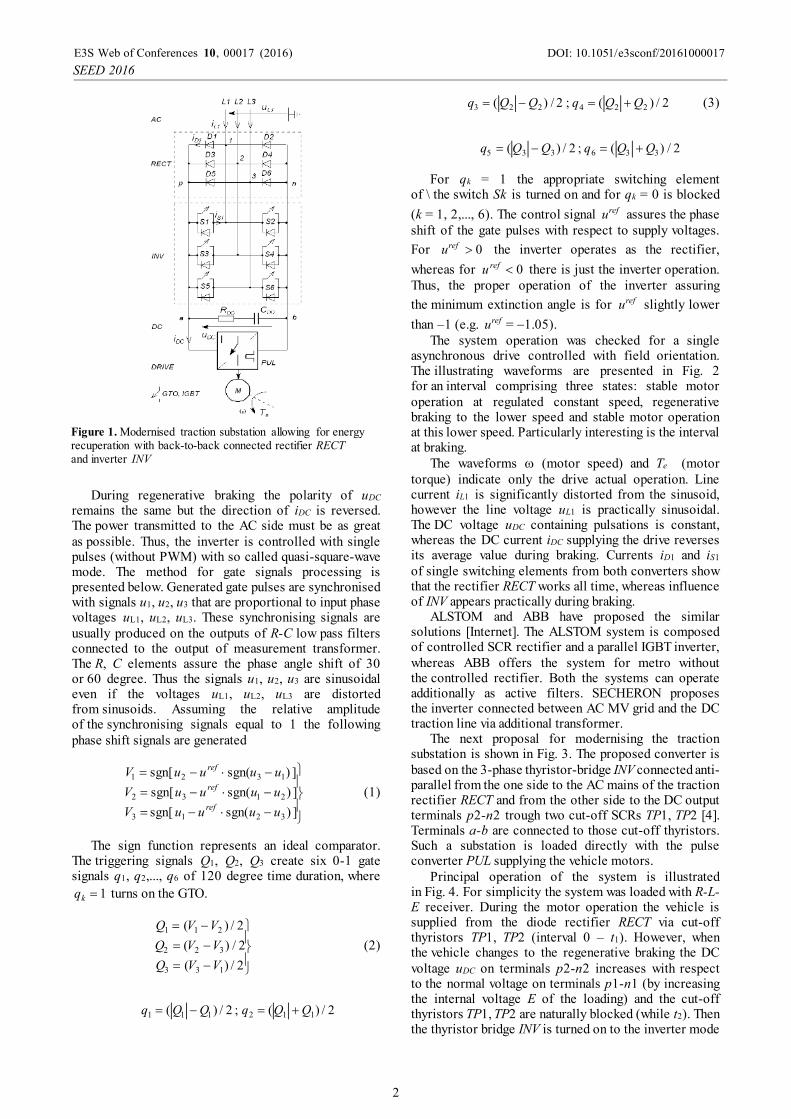
The system operation was checked for a single asynchronous drive controlled with field orientation. The illustrating waveforms are presented in Fig. 2 for an interval comprising three states: stable motor operation at regulated constant speed, regenerative braking to the lower speed and stable motor operation at this lower speed. Particularly interesting is the interval at braking.
The waveforms (motor speed) and Te (motor torque) indicate only the drive actual operation. Line current iL1 is significantly distorted from the sinusoid, however the line voltage uL1 is practically sinusoidal. The DC voltage uDC containing pulsations is constant, whereas the DC current iDC supplying the drive reverses its average value during braking. Currents iD1 and iS1 of single switching elements from both converters show that the rectifier RECT works all time, whereas influence of INV appears practically during braking.
ALSTOM and ABB have proposed the similar solutions [Internet]. The ALSTOM system is composed of controlled SCR rectifier and a parallel IGBT inverter, whereas ABB offers the system for metro without the controlled rectifier. Both the systems can operate additionally as active filters. SECHERON proposes the inverter connected between AC MV grid and the DC traction line via additional transformer.
The next proposal for modernising the traction substation is shown in Fig. 3. The proposed converter is based on the 3-phase thyristor-bridge INV connected anti-parallel from the one side to the AC mains of the traction rectifier RECT and from the other side to the DC output terminals p2-n2 trough two cut-off SCRs TP1, TP2 [4]. Terminals a-b are connected to those cut-off thyristors. Such a substation is loaded directly with the pulse converter PUL supplying the vehicle motors.
Principal operation of the system is illustrated in Fig. 4. For simplicity the system was loaded with R-L-E receiver. During the motor operation the vehicle is supplied from the diode rectifier RECT via cut-off thyristors TP1, TP2 (interval 0 – t1). However, when the vehicle changes to the regenerative braking the DC voltage uDC on terminals p2-n2 increases with respect to the normal voltage on terminals p1-n1 (by increasing the internal voltage E of the loading) and the cut-off thyristors TP1, TP2 are naturally blocked (while t2). Then the thyristor bridge INV is turned on to the inverter mode
Figure 1. Modernised traction substation allowing for energy recuperation with back-to-back connected rectifier RECT and inverter INV
DOI: 10.1051/
2016,10 1000017e3sconf/2016E3S Web of Conferences
SEED
00017 (2016)
2
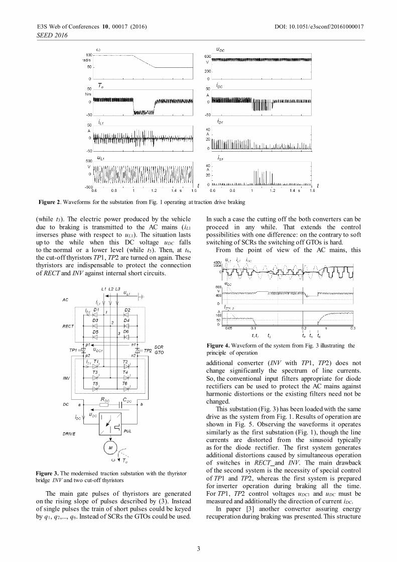
(while t3). The electric power produced by the vehicle due to braking is transmitted to the AC mains (iL1 inverses phase with respect to uL1). The situation lasts up to the while when this DC voltage uDC falls to the normal or a lower level (while t5). Then, at t6, the cut-off thyristors TP1, TP2 are turned on again. These thyristors are indispensable to protect the connection of RECT and INV against internal short circuits.
The main gate pulses of thyristors are generated on the rising slope of pulses described by (3). Instead of single pulses the train of short pulses could be keyed by q1, q2,..., q6. Instead of SCRs the GTOs could be used.
In such a case the cutting off the both converters can be proceed in any while. That extends the control possibilities with one difference: on the contrary to soft switching of SCRs the switching off GTOs is hard.
From the point of view of the AC mains, this
additional converter (INV with TP1, TP2) does not change significantly the spectrum of line currents. So, the conventional input filters appropriate for diode rectifiers can be used to protect the AC mains against harmonic distortions or the existing filters need not be changed.
This substation (Fig. 3) has been loaded with the same drive as the system from Fig. 1. Results of operation are shown in Fig. 5. Observing the waveforms it operates similarly as the first substation (Fig. 1), though the line currents are distorted from the sinusoid typically as for the diode rectifier. The first system generates additional distortions caused by simultaneous operation of switches in RECT and INV. The main drawback of the second system is the necessity of special control of TP1 and TP2, whereas the first system is prepared for inverter operation during braking all the time. For TP1, TP2 control voltages uDC1 and uDC must be measured and additionally the direction of current iDC.
In paper [3] another converter assuring energy recuperation during braking was presented. This structure
Figure 3. The modernised traction substation with the thyristor bridge INV and two cut-off thyristors
Figure 2. Waveforms for the substation from Fig. 1 operating at traction drive braking
Figure 4. Waveform of the system from Fig. 3 illustrating the principle of operation
DOI: 10.1051/
2016,10 1000017e3sconf/2016E3S Web of Conferences
SEED
00017 (2016)
3
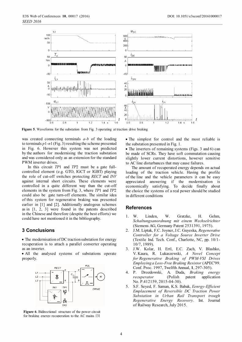
was created connecting terminals a-b of the loading to terminals p1-n1 (Fig. 3) resulting the scheme presented in Fig. 6. However this system was not predicted by the authors for modernising the traction substation and was considered only as an extension for the standard PWM inverter drives.
In this circuit TP1 and TP2 must be a gate full-controlled element (e.g. GTO, IGCT or IGBT) playing the role of cut-off switches protecting RECT and INV against internal short circuits. These elements were controlled in a quite different way than the cut-off elements in the system from Fig. 3, where TP1 and TP2 could also be gate turn-off elements. The similar idea of this system for regenerative braking was presented earlier in [1] and [2]. Additionally analogous schemes as in [1, 2, 3] were found in the patents described in the Chinese and therefore (despite the best efforts) we could have not mentioned it in the bibliography.
3 Conclusions
The modernisation of DC traction substation for energy recuperation is to attach a parallel converter operating as an inverter. All the analysed systems of substations operate properly.
The simplest for control and the most reliable is the substation presented in Fig. 1. The inverters of remaining systems (Figs. 3 and 6) can be made of SCRs. They have soft commutation causing slightly lower current distortions, however sensitive to AC line disturbances that may cause failures.
The amount of recuperated energy depends on actual loading of the traction vehicle. Having the profile of the line and the vehicle parameters it can be easy appreciated answering if the modernisation is economically satisfying. To decide finally about the choice the systems of a real power should be studied in different conditions
References
1. W. Linden, W. Gratzke, H. Gehm, Schaltungsanordnung mit einem Wechselrichter (Siemens AG, Germany Patent 2531391, 1975).
2. J.M. Liptak, F.C. Joyner, J.C. Guyeska, Regenerative Controller for a Voltage Source Inverter Drive (Textile Ind. Tech. Conf., Charlotte, NC, pp. 10/1-10/7, 1989).
3. J.W. Kolar, H. Ertl, E.C. Zach, V. Blashko, V. Kaura, R. Lukaszewski, A Novel Concept for Regenerative Braking of PWM-VSI Drives Employing a Loss-Free Braking Resistor (APEC'99. Conf. Proc. 1997, Twelfth Annual, 1, 297-305).
4. P. Drozdowski, A. Duda, Braking energy recuperator (Polish patent application No. P.412159, 2015-04-30).
5. S.F. Seyed, F. Saman, K.S. Babak, Eenrgy-Efficient Emplacement of Reversible DC Traction Power Substation in Urban Rail Transport trough Regenerative Energy Recovery. Int. Journal of Railway Research, July 2015.
Figure 5. Waveforms for the substation from Fig. 3 operating at traction drive braking
Figure 6. Bidirectional structure of the power circuit for braking energy recuperation to the AC mains [3]
DOI: 10.1051/
2016,10 1000017e3sconf/2016E3S Web of Conferences
SEED
00017 (2016)
4