Embed Size (px)
Citation preview
Montage- undBedienungsanleitung (S. 2)Mounting instruction andoperating manual (p. 21)
Funk LAN GatewayWireless LAN Gateway
HM-LGW-O-TW-W-EU-2
2
Dokumentation © 2015 eQ-3 AG, DeutschlandAlle Rechte vorbehalten. Ohne schriftliche Zustim-mung des Herausgebers darf dieses Handbuch auch nicht auszugsweise in irgendeiner Form reproduziert werden oder unter Verwendung elektronischer, mecha-nischer oder chemischer Verfahren vervielfältigt oder verarbeitet werden.Es ist möglich, dass das vorliegende Handbuch noch drucktechnische Mängel oder Druckfehler aufweist. Die Angaben in diesem Handbuch werden jedoch regelmäßig überprüft und Korrekturen in der nächsten Ausgabe vorgenommen. Für Fehler technischer oder drucktechnischer Art und ihre Folgen übernehmen wir keine Haftung.Alle Warenzeichen und Schutzrechte werden aner-kannt.Printed in Hong Kong.Änderungen im Sinne des technischen Fortschritts können ohne Vorankündigung vorgenommen werden.
141870V 1.2 (12/2016)
3
Inhaltsverzeichnis
1 Hinweise zu dieser Anleitung . . . . . . . . . . . . . . 42 Gefahrenhinweise . . . . . . . . . . . . . . . . . . . . . . 43 Funktion . . . . . . . . . . . . . . . . . . . . . . . . . . . . . . 64 Allgemeine Systeminformation zu Homematic. 85 Inbetriebnahme . . . . . . . . . . . . . . . . . . . . . . . . 85.1 Wandmontage . . . . . . . . . . . . . . . . . . . . . . . . . 85.2 Funk LAN Gateway mit dem Netzwerk
verbinden . . . . . . . . . . . . . . . . . . . . . . . . . . . . 105.3 Funk LAN Gateway an die Stromversorgung
anschließen . . . . . . . . . . . . . . . . . . . . . . . . . . 115.4 Einbinden ins Netzwerk . . . . . . . . . . . . . . . . . 116 Rück- und Fehlermeldungendurch die
Geräte LED . . . . . . . . . . . . . . . . . . . . . . . . . . 157 Werkseinstellungen des Gerätes
wiederherstellen . . . . . . . . . . . . . . . . . . . . . . . 168 Duty Cycle . . . . . . . . . . . . . . . . . . . . . . . . . . . 179 Wartung und Reinigung . . . . . . . . . . . . . . . . . 1810 Lieferumfang . . . . . . . . . . . . . . . . . . . . . . . . . 1811 Technische Daten. . . . . . . . . . . . . . . . . . . . . . 19
4
1 Hinweise zu dieser Anleitung
Lesen Sie diese Anleitung sorgfältig, bevor Sie Ihre Homematic Komponenten in Betrieb nehmen. Bewah-ren Sie die Anleitung zum späteren Nachschlagen auf! Wenn Sie das Gerät anderen Personen zur Nutzung überlassen, übergeben Sie auch diese Bedienungs-anleitung.
Benutzte Symbole:Achtung! Hier wird auf eine Gefahr hingewiesen.
Hinweis. Dieser Abschnitt enthält zusätzliche wichtige Informationen!
2 Gefahrenhinweise
Bei Sach- oder Personenschäden, die durch unsachgemäße Handhabung oder Nichtbe-achten der Gefahrenhinweise verursacht werden, übernehmen wir keine Haftung. In solchen Fällen erlischt jeder Gewährleistungs-anspruch! Für Folgeschäden übernehmen wir keine Haftung!
5
Öffnen Sie das Gerät nicht. Es enthält keine durch den Anwender zu wartenden Teile. Im Fehlerfall schicken Sie das Gerät an den Service.
Das Gerät nicht verwenden, wenn es von außen erkennbare Schäden z. B. am Gehäu-se, an Bedienelementen oder an den An-schlussbuchsen bzw. eine Funktionsstörung aufweist. Im Zweifelsfall lassen Sie das Gerät von einer Fachkraft prüfen.
Aus Sicherheits- und Zulassungsgründen (CE) ist das eigenmächtige Umbauen und/oder Verändern des Produkts nicht gestattet.
Betreiben Sie das Gerät nur in Innenräumen und setzen Sie es keinem Einfluss von Feuch-tigkeit, Vibrationen, ständiger Sonnen- oder anderer Wärmeeinstrahlung, Kälte und keinen mechanischen Belastungen aus.
Das Gerät ist kein Spielzeug, erlauben Sie Kin-dern nicht damit zu spielen. Lassen Sie das Verpackungsmaterial nicht achtlos liegen, Plastikfolien/-tüten, Styroporteile, etc., könnten für Kinder zu einem gefährlichen Spielzeug werden.
6
Benutzen Sie für die Stromversorgung des Gerätes ausschließlich das mitgelieferte Origi-nalnetzteil (5 VDC/1500 mA).
Das Gerät darf nur an eine leicht zugängliche Netz-Steckdose angeschlossen werden. Bei Gefahr ist der Netzstecker zu ziehen.
Verlegen Sie Kabel stets so, dass diese nicht zu Gefährdungen für Menschen und Haustiere führen können.
Jeder andere Einsatz, als in dieser Bedie-nungsanleitung beschriebene, ist nicht be-stimmungsgemäß und führt zu Gewährlei-stungs- und Haftungsausschluss.
Das Gerät ist nur für den Einsatz in woh-nungsähnlichen Umgebungen geeignet.
3 Funktion
Das Homematic Funk LAN Gateway dient als Erweiterung der Funkreichweite Ihrer CCU2 in einem Homematic System. Wenn Sie Homematic Geräte außerhalb der direkten Reichweite Ihrer CCU
7
verwenden, z. B. im Keller, im Obergeschoss Ihres Hauses oder im Gartenhaus, unterstützt das Funk LAN Gateway bei der Übertragung von Funkbefehlen an diese Geräte. Sie können mehrere Funk LAN Gateways in Ihrem Homematic System verwenden.
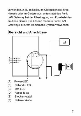
Übersicht und Anschlüsse
BC
D E
Power
Network
Info
A
F(A) Power-LED(B) Network-LED(C) Info-LED(D) Reset-Taste(E) Steckernetzteil(F) Netzwerkkabel

8
4 Allgemeine Systeminformation zu Homematic
Dieses Gerät ist Teil des Homematic Haussteuer-systems und arbeitet mit dem bidirektionalen Funkpro-tokoll BidCoS®.Alle technischen Dokumente und Updates finden Sie stets aktuell unter www.homematic.com.
5 Inbetriebnahme
Um das Funk LAN Gateway in Betrieb zu nehmen, führen Sie die folgenden Schritte durch:• Montage• Verbinden mit dem Netzwerk• Anschließen an die Stromversorgung• Einbinden ins Netzwerk
5.1 WandmontageSie können das Funk LAN Gateway als Standgerät einsetzen oder an der Wand montieren. Für die Wand-montage gehen Sie wie folgt vor:
Bitte notieren Sie sich vor der Montage die Seriennummer sowie den Zugriffscode des Funk LAN Gateways. Diese können Sie den Aufkle-bern auf der Gehäuserückseite entnehmen.

9
Verwenden Sie für die Wandmontage die zwei mitge-lieferten Schrauben und Dübel.
Stellen Sie bei der Auswahl des Montageortes und beim Bohren in der Nähe vorhandener Schalter oder Steckdosen sicher, dass in der Wand keine Leitungen verlaufen.
• Halten Sie die beiliegende Bohrschablone an die vorgesehene Montagestelle und richten Sie die Bohrschablone senkrecht bzw. waagerecht aus.
• Markieren Sie die Bohrlöcher A und B auf der Bohr-schablone mit einem Stift durch die Bohrschablone an der Wand.
• Bohren Sie die zwei markierten Löcher mit einem Durchmesser von 5 mm in die Wand. Stecken Sie die Dübel in die Bohrungen. Drehen Sie die Schrau-ben so in die Dübel, dass sie ca. 1,5 mm aus der Wand heraus stehen. Hängen Sie das Gerät mit den rückseitigen Halterungen (J) von oben bzw. rechts hinter die Schraubenköpfe ein.
10
J
J
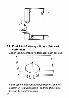
5.2 Funk LAN Gateway mit dem Netzwerk verbinden
• Ziehen Sie zunächst die Abdeckkappe nach oben ab.
• Schließen Sie das Funk LAN Gateway mit dem mit-gelieferten Netzwerkkabel (F) an Ihren DSL-Router bzw. an Ihr Kabelmodem an.
11
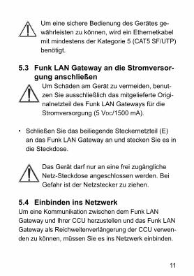
Um eine sichere Bedienung des Gerätes ge-währleisten zu können, wird ein Ethernetkabel mit mindestens der Kategorie 5 (CAT5 SF/UTP) benötigt.
5.3 Funk LAN Gateway an die Stromversor-gung anschließen
Um Schäden am Gerät zu vermeiden, benut-zen Sie ausschließlich das mitgelieferte Origi-nalnetzteil des Funk LAN Gateways für die Stromversorgung (5 VDC/1500 mA).
• Schließen Sie das beiliegende Steckernetzteil (E) an das Funk LAN Gateway an und stecken Sie es in die Steckdose.
Das Gerät darf nur an eine frei zugängliche Netz-Steckdose angeschlossen werden. Bei Gefahr ist der Netzstecker zu ziehen.
5.4 Einbinden ins NetzwerkUm eine Kommunikation zwischen dem Funk LAN Gateway und Ihrer CCU herzustellen und das Funk LAN Gateway als Reichweitenverlängerung der CCU verwen-den zu können, müssen Sie es ins Netzwerk einbinden.
12
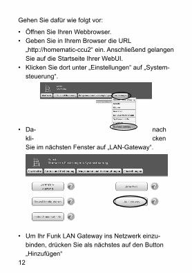
Gehen Sie dafür wie folgt vor:
• Öffnen Sie Ihren Webbrowser.• Geben Sie in Ihrem Browser die URL
„http://homematic-ccu2“ ein. Anschließend gelangen Sie auf die Startseite Ihrer WebUI.
• Klicken Sie dort unter „Einstellungen“ auf „System-steuerung“.
• Da- nach kli- cken Sie im nächsten Fenster auf „LAN-Gateway“.
• Um Ihr Funk LAN Gateway ins Netzwerk einzu-binden, drücken Sie als nächstes auf den Button „Hinzufügen“

13
• Wählen Sie den Typ „RF: Homematic RF-LAN Gate-way“ aus.
• Entnehmen Sie die Seriennummer und den Zugriffs-code Ihres Funk LAN Gateways Ihren Notizen oder den Aufklebern auf der Gehäuserückseite.
• Geben Sie diese in den entsprechenden Feldern ein.
• Bestätigen Sie anschließend mit „OK“.
Ihr Funk LAN Gateway wird in der Bedienoberfläche angezeigt. Um es zu aktivieren, klicken Sie auf „Über-nehmen“ und führen Sie einen Neustart Ihrer CCU durch.
14
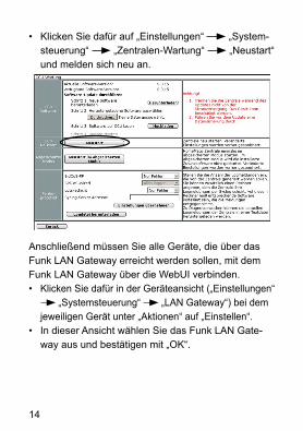
• Klicken Sie dafür auf „Einstellungen“ „System-steuerung“ „Zentralen-Wartung“ „Neustart“ und melden sich neu an.
Anschließend müssen Sie alle Geräte, die über das Funk LAN Gateway erreicht werden sollen, mit dem Funk LAN Gateway über die WebUI verbinden.• Klicken Sie dafür in der Geräteansicht („Einstellungen“
„Systemsteuerung“ „LAN Gateway“) bei dem jeweiligen Gerät unter „Aktionen“ auf „Einstellen“.
• In dieser Ansicht wählen Sie das Funk LAN Gate-way aus und bestätigen mit „OK“.

15
Jetzt können Sie die ausgewählten Geräte Ihres Homematic Systems über das Funk LAN Gateway erreichen.
6 Rück- und Fehlermeldungen durch die Geräte LED
Power LED BedeutungAus Gerät ist abgeschaltetEin Gerät ist betriebsbereitSchnelles Blinken Bootloader aktivLangsames Blinken Werkseinstellungen wieder-
herstellen
Network LED BedeutungAus LAN inaktiv bzw. Netzwerkka-
bel nicht eingestecktEin LAN aktiv, Verbindung aktivLangsames Blinken Störung bzw. keine Verbindung
(zur CCU) - Bitte prüfen Sie den Status Ihrer CCU
16
Die Info LED kann Fehler- und Alarmmeldungen der CCU wiedergeben. Hierbei sind Verzöge-rungen bis zu 10 s für die Übertragung der Meldungen möglich.
7 Werkseinstellungen des Gerätes wiederherstellen
Die Werkseinstellungen des Homematic Funk LAN Gateways können manuell wieder hergestellt werden. Dabei gehen alle Einstellungen und Informationen verloren.
Bevor Sie die Werkseinstellungen des Gerätes wieder herstellen, löschen Sie es zuerst aus der Homematic Bedienoberfläche WebUI.
Um die Werkseinstellungen wieder herzustellen, gehen Sie wie folgt vor:• Drücken Sie die Reset-Taste für ca. 6 Sekunden. Die
schnell blinkende LED zeigt den Löschmodus an.• Lassen Sie die Taste los.• Drücken Sie die Taste erneut für ca. 3 Sekunden,
bis die LED langsam blinkt. • Lassen Sie die Taste los.• Die LED erlischt nach kurzer Zeit und die Werksein-
stellungen des Gerätes sind wiederhergestellt.
17
8 Duty Cycle
Der Duty Cycle beschreibt eine gesetzlich geregelte Begrenzung der Sendezeit von Geräten im 868 MHz Bereich. Das Ziel dieser Regelung ist es, die Funktion aller im 868 MHz Bereich arbeitenden Geräte zu ge-währleisten.
In dem von uns genutzten Frequenzbereich 868 MHz beträgt die maximale Sendezeit eines jeden Gerätes 1 % einer Stunde (also 36 Sekunden in einer Stunde). Die Geräte dürfen bei Erreichen des 1 %-Limits nicht mehr senden, bis diese zeitliche Begrenzung vorüber ist. Gemäß dieser Richtlinie, werden Homematic-Geräte zu 100 % normenkonform entwickelt und produziert.
Im normalen Betrieb wird der Duty Cycle in der Regel nicht erreicht. Dies kann jedoch in Einzelfällen bei der Inbetriebnahme oder Erstinstallation eines Systems durch vermehrte und funkintensive Anlernprozesse der Fall sein. Eine Überschreitung des Duty Cycle Limits kann sich durch temporär fehlende Funktion des Ge-rätes äußern. Nach kurzer Zeit (max. 1 Stunde) ist die Funktion des Gerätes wiederhergestellt.

18
9 Wartung und Reinigung
Das Produkt ist wartungsfrei. Überlassen Sie eine Reparatur einer Fachkraft. Reinigen Sie das Produkt mit einem weichen, sauberen, trockenen und fusselfreien Tuch. Für die Entfernung von stärkeren Verschmutzungen kann das Tuch leicht mit lauwarmem Wasser angefeuchtet werden. Verwenden Sie keine lösemittelhaltigen Reinigungsmittel, das Kunst-stoffgehäuse und die Beschriftung kann dadurch angegriffen werden.
10 Lieferumfang
• Homematic Funk LAN Gateway• Steckernetzteil• Netzwerkkabel• Montagematerial• Bohrschablone• Montage- und Bedienungsanleitung
19
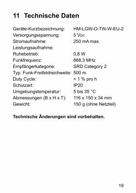
11 Technische Daten
Geräte-Kurzbezeichnung: HM-LGW-O-TW-W-EU-2Versorgungsspannung: 5 VDC
Stromaufnahme: 250 mA max.LeistungsaufnahmeRuhebetrieb: 0,8 WFunkfrequenz: 868,3 MHzEmpfängerkategorie: SRD Category 2Typ. Funk-Freifeldreichweite: 500 mDuty Cycle: < 1 % pro hSchutzart: IP20Umgebungstemperatur: 5 bis 35 °CAbmessungen (B x H x T): 116 x 150 x 34 mmGewicht: 150 g (ohne Netzteil)
Technische Änderungen sind vorbehalten.

20
Entsorgungshinweis:Gerät nicht im Hausmüll entsorgen! Elektro-nische Geräte sind entsprechend der Richtli-nie über Elektro- und Elektronik-Altgeräte über die örtlichen Sammelstellen für Elektronik-Altgeräte zu entsorgen.
Das CE-Zeichen ist ein Freiverkehrszeichen, das sich ausschließlich an die Behörden wendet und keine Zusicherung von Eigen-schaften beinhaltet.
Bei technischen Fragen zum Gerät, wenden Sie sich bitte an Ihren Fachhändler.
21
Documentation © 2015 eQ-3 AG, GermanyAll rights reserved. This manual may not be repro-duced in any format, either in whole or in part, nor may it be duplicated or edited by electronic, mechanical or chemical means, without the written consent of the publisher.Typographical and printing errors cannot be excluded. However, the information contained in this manual is reviewed on a regular basis and any necessary cor-rections will be implemented in the next edition. We accept no liability for technical or typographical errors or the consequences thereof.All trademarks and industrial property rights are ac-knowledged.Printed in Hong Kong.Changes may be made without prior notice as a result of technical advances.Translation of original version in German.
141870V 1.2 (12/2016)
22
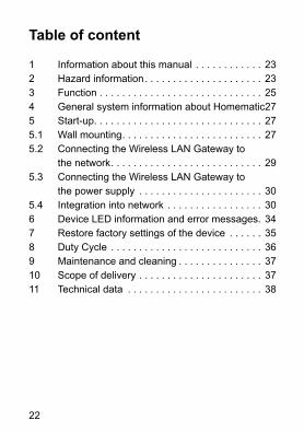
Table of content
1 Information about this manual . . . . . . . . . . . . 232 Hazard information. . . . . . . . . . . . . . . . . . . . . 233 Function . . . . . . . . . . . . . . . . . . . . . . . . . . . . . 254 General system information about Homematic 275 Start-up. . . . . . . . . . . . . . . . . . . . . . . . . . . . . . 275.1 Wall mounting. . . . . . . . . . . . . . . . . . . . . . . . . 275.2 Connecting the Wireless LAN Gateway to
the network. . . . . . . . . . . . . . . . . . . . . . . . . . . 295.3 Connecting the Wireless LAN Gateway to
the power supply . . . . . . . . . . . . . . . . . . . . . . 305.4 Integration into network . . . . . . . . . . . . . . . . . 306 Device LED information and error messages. 347 Restore factory settings of the device . . . . . . 358 Duty Cycle . . . . . . . . . . . . . . . . . . . . . . . . . . . 369 Maintenance and cleaning . . . . . . . . . . . . . . . 3710 Scope of delivery . . . . . . . . . . . . . . . . . . . . . . 3711 Technical data . . . . . . . . . . . . . . . . . . . . . . . . 38

23
1 Information about this manual
Read this manual carefully before beginning operation with your Homematic components. Keep the manual handy for later consultation! If you hand over the de-vice to other persons for use, please hand over the operating manual as well.
Symbols used:Attention! This indicates a hazard.
Note. This section contains important addi-tional information.
2 Hazard information
We do not assume any liability for damage to property or personal injury caused by improper use or the failure to observe the hazard infor-mation. In such cases any claim under warran-ty is extinguished! For consequential dama-ges, we assume no liability!

24
Do not open the device. It does not contain any parts that can be maintained by the user. In the event of an error, have the device che-cked by an expert.
Do not use the device if there are signs of damage to the housing, control elements or connecting sockets, for example, or if it de-monstrates a malfunction. If you have any doubts, have the device checked by an expert or by our service department.
For safety and licensing reasons (CE), un-authorized change and/or modification of the product is not permitted.
The device may only be operated indoors and must be protected from the effects of moisture, vibrations, solar or other methods of heat radiation, cold and mechanical loads.
The device is not a toy; do not allow children to play with it. Do not leave packaging material lying around, plastic films/bags, pieces of polystyrene etc., can be dangerous in the hands of a child.
25
For power supply, only use the original power supply unit (5 VDC/1500 mA) delivered with the device.
The device may only be connected to an easily accessible power socket outlet. The mains plug must be pulled out if a hazard occurs.
Always lay cables in such a way that they do not become a risk to people and domestic animals.
Using this device for any purpose other than that described in this operating manual does not fall within the scope of intended use and shall invalidate any warranty or liability.
The device may only be operated whitin residential buildings.
3 Function
The Homematic Wireless LAN Gateway increases the transmission range of your Homematic CCU2 within a Homematic installation. If you want to use Homematic devices that are not within the scope of radio trans-
26
mission of your CCU (e.g. in the cellar, the top floor of your house or your summer house) the repeater increases the radio transmission of your devices.You can use several Wireless LAN Gateways within your Homematic system.
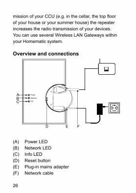
Overview and connections
BC
D E
Power
Network
Info
A
F
(A) Power LED(B) Network LED(C) Info LED(D) Reset button(E) Plug-in mains adapter(F) Network cable

27
4 General system information about Homematic
This device is part of the Homematic home control system and works with the bidirectional BidCoS® wireless protocol.All current technical documents and updates are provided at www.homematic.com.
5 Start-up
To start up your Wireless LAN Gateway, please pro-ceed as follows:• Mount the device• Establish network connection• Connect to the power supply• Integrate the device into network
5.1 Wall mountingYou can use your Wireless LAN Gateway as stand-ing device or mount it to the wall. For wall mounting, please proceed as follows:
Before installation, please note the serial number and the access code of your Wireless LAN Gateway. You will find the details on the sticker at the back of the device.

28
Hold the drilling template supplied (see additional sheet) at your intended mounting location and align it vertically and/or horizontally.
When selecting a mounting location and drill-ing in the vicinity of switches or socket outlets, make sure that there are no cables in the wall.
• Hold the drilling template supplied (see additional sheet) at your intended mounting location and align it vertically and/or horizontally.
• Use a pen to mark the bore holes A and B (as shown on the drilling template) on the wall through the template.
• Drill the two marked holes into the wall with a diam-eter of 5 mm. Insert the plugs in the holes. Turn the screws into the plugs so that they protrude from the wall by approx. 1.5 mm. Working from above/from the right, hang the device using the brackets on the back (J) behind the screw heads.
29
J
J
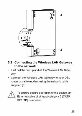
5.2 Connecting the Wireless LAN Gateway to the network
• First pull the cap up and off the Wireless LAN Gate-way.
• Connect the Wireless LAN Gateway to your DSL router or cable modem using the network cable supplied (F).
To ensure secure operation of the device, an Ethernet cable of at least category 5 (CAT5 SF/UTP) is required.
30
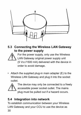
5.3 Connecting the Wireless LAN Gateway to the power supply
For the power supply, only use the Wireless LAN Gateway original power supply unit(5 VDC/1500 mA) delivered with the device in order to avoid damage.
• Attach the supplied plug-in main adapter (E) to the Wireless LAN Gateway and plug it into the socket outlet.
The device may only be connected to a freely accessible power socket outlet. The mains plug must be pulled out if a hazard occurs.
5.4 Integration into networkTo establish communication between your Wireless LAN Gateway and your CCU to use the device as

31
range extension of your CCU, it has to be integrated into the network.
Therefore, please proceed as follows:
• Open your web browser.• Enter the URL „http://homematic-ccu2“ into your
browser. You will then be taken to the homepage of your WebUI.
• Please click on "Settings" and "Control panel".
• In the next window, please select "LAN Gateway".
32
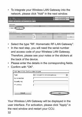
• To integrate your Wireless LAN Gateway into the network, please click "Add" in the next window.
• Select the type "RF: Homematic RF-LAN Gateway".• In the next step, you will need the serial number
and access code of your Wireless LAN Gateway. Therefore, please see your notes or the stickers at the back of the device.
• Please enter the details in the corresponding fields.• Confirm with "OK".
Your Wireless LAN Gateway will be displayed in the user interface. For activation, please click "Apply" in the next window and restart your CCU.

33
• Therefore, please click "Settings" "Control panel" "CCU maintenance" "Restart" and log in again.
Afterwards, please use the WebUI interface to connect the Wireless LAN Gateway with all the devices that have to be reached via the Wireless LAN Gateway.• Therefore, please select in the device overview
("Settings" "Control panel" "LAN Gateway") under "Action" the option "Set" for each device.
• You can select the Wireless LAN Gateway in the next window and confirm with "OK".

34
Now the selected devices of your Homematic system can be reached via the Wireless LAN Gateway.
6 Device LED information and error messages
Power LED MeaningOff Device is turned offOn Device is ready for operationFast flashing Boot loader activeSlow flashing Restore factory settings
Network LED MeaningOff LAN inactive or network cable not
connectedOn LAN active, connection activeSlow flashing Malfunction or no connection (to
the CCU) - Please check the status of your CCU.

35
The Info LED provides information about error and alarm messages of the CCU. The transmis-sion of messages may be delayed by max. 10s.
7 Restore factory settings of the device
The factory settings of the Homematic Wireless LAN Gateway can be restored manually. If you do this, you will lose all your settings.
Before restoring the factory settings, please delete the device from the user interface WebUI first.
To restore the factory settings, please proceed as follows:• Press the “Reset” button (D) for approx. 6 seconds.
The quickly flashing LED indicates delete mode.• Release the button.• Press the button again for approx. 3 seconds until
the LED flashes slowly. • Release the button again.• The LED expires after a short time and the factory
settings of the device will be restored.
36
8 Duty Cycle
The duty cycle is a legally regulated limit of the trans-mission time of devices in the 868 MHz range. The aim of this regulation is to safeguard the operation of all devices working in the 868 MHz range.In the 868 MHz frequency range we use, the maximum transmission time of any device is 1% of an hour (i.e. 36 seconds in an hour). Devices must cease trans-mission when they reach the 1% limit until this time restriction comes to an end.
Homematic devices are designed and produced with 100% conformity to this regulation.
During normal operation, the duty cycle is not usually fully used up. However, repeated and wireless-inten-sive teach-in processes mean that it may be reached in isolated instances during start-up or initial installa-tion of a system. If the duty cycle limit is exceeded, this is indicated if your Homematic device is temporarily working incorrectly. The device will start working cor-rectly again after a short period (max. 1 hour).
37
9 Maintenance and cleaning
The product does not require any maintenance. Enlist the help of an expert to carry out any maintenance or repairs. Clean the product using a soft, lint-free cloth that is clean and dry. You may dampen the cloth a little with lukewarm water in order to remove more stubborn marks. Do not use any detergents containing solvents, as they could corrode the plastic housing and label.
10 Scope of delivery
• Homematic Wireless LAN Gateway• Plug-in mains adapter• Network cable• Mounting material• Drilling template• Mounting and operating manual
38
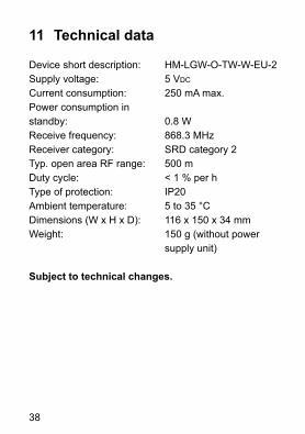
11 Technical data
Device short description: HM-LGW-O-TW-W-EU-2Supply voltage: 5 VDC
Current consumption: 250 mA max.Power consumption instandby: 0.8 WReceive frequency: 868.3 MHzReceiver category: SRD category 2Typ. open area RF range: 500 mDuty cycle: < 1 % per hType of protection: IP20Ambient temperature: 5 to 35 °CDimensions (W x H x D): 116 x 150 x 34 mmWeight: 150 g (without power supply unit)
Subject to technical changes.

39
Instructions for disposal:Do not dispose of the device with regular domestic waste. Electronic equipment must be disposed of at local collection points for waste electronic equipment in compliance with the Waste Electrical and Electronic Equipment Directive.
The CE sign is a free trading sign addressed exclusively to the authorities and does not include any warranty of any properties.
For technical support, please contact your speciallist dealer.
40
Bevollmächtigter des Herstellers:Manufacturer’s authorised representative:
eQ-3 AGMaiburger Straße 2926789 Leer / GERMANYwww.eQ-3.de