Embed Size (px)
Citation preview
CEAG Notlichtsysteme GmbH 2
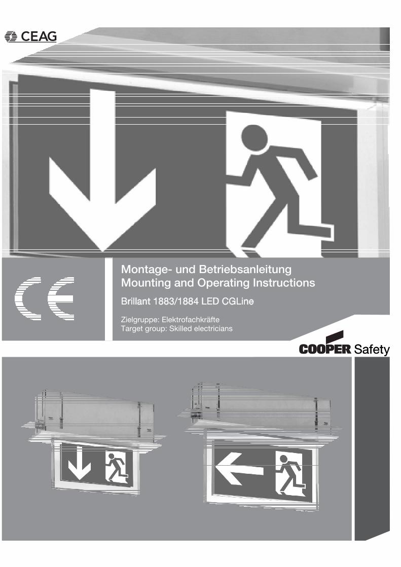
Montage- und BetriebsanleitungBrillant LED Deckeneinbau-Einzelbatterieleuchte1883...1884 LED CGLine
Inhaltsverzeichnis
1 Aufbau der Leuchte / Construction of the luminaire ............................. 3
2 Maßbilder / Dimensional Drawings ....................................................... 4
3 Sicherheitshinweise .............................................................................. 5
4 Normenkonformität ............................................................................... 5
5 Technische Daten .................................................................................. 5 5.1 Verwendungsbereich / Kurzbeschreibung ................................................................. 6
6 Installation / Inbetriebnahme ................................................................. 6 6.1 Montage ..................................................................................................................... 6 6.2 Überwachtungseinrichtung CGLine ........................................................................... 7 6.3 Dimmlevel ................................................................................................................... 8 6.4 Einstellung der Betriebsart ......................................................................................... 8 6.5 Kontroll LEDs ............................................................................................................. 9
7 Wartung / Instandhaltung ...................................................................... 9
8 Entsorgung / Recycling ......................................................................... 9
3 Safety notes ........................................................................................ 10
4 Conformity with standards .................................................................. 10
5 Technical data ..................................................................................... 10 5.1 Brief description / Scope of application ................................................................... 11
6 Installation ........................................................................................... 11 6.1 Mounting .................................................................................................................. 11 6.2 CGLine Monitoring Device ....................................................................................... 12 6.3 Dim-Level ................................................................................................................. 13 6.4 Operation mode ....................................................................................................... 13 6.5 Control LEDs ............................................................................................................ 14
7 Servicing ............................................................................................. 14
8 Recycling............................................................................................. 14
CEAG Notlichtsysteme GmbH 3
Montage- und BetriebsanleitungBrillant LED Deckeneinbau-Einzelbatterieleuchte1883...1884 LED CGLine
Brillant 1883...1884 LED CGLine
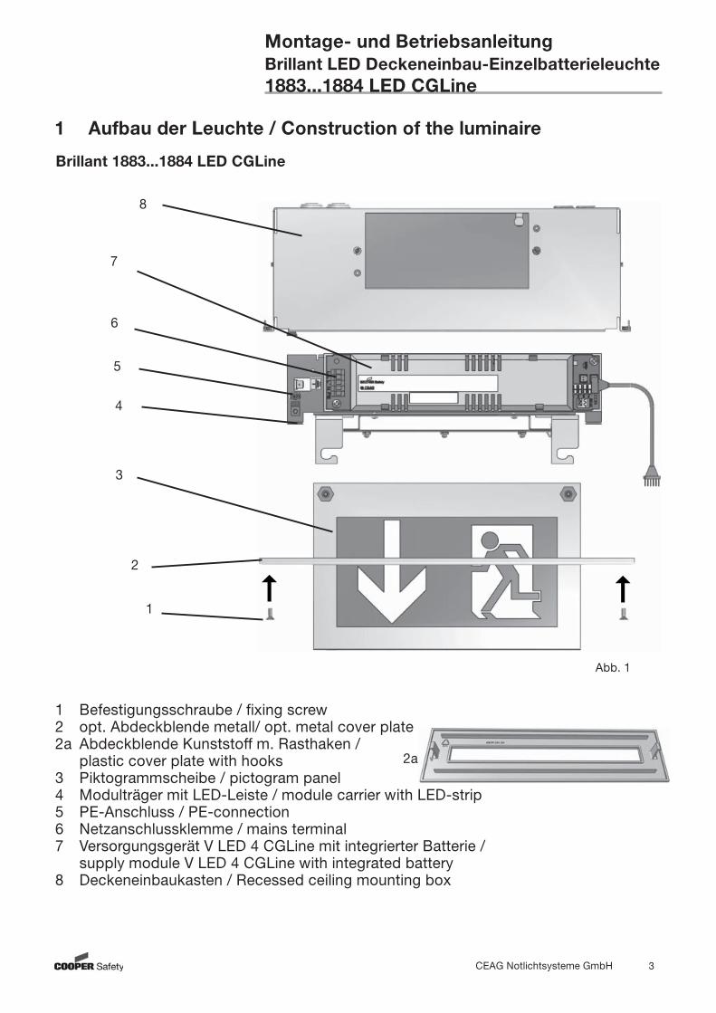
1 Aufbau der Leuchte / Construction of the luminaire
Abb. 1
1 Befestigungsschraube / fixing screw2 opt. Abdeckblende metall/ opt. metal cover plate2a Abdeckblende Kunststoff m. Rasthaken / plastic cover plate with hooks3 Piktogrammscheibe / pictogram panel4 Modulträger mit LED-Leiste / module carrier with LED-strip5 PE-Anschluss / PE-connection6 Netzanschlussklemme / mains terminal7 Versorgungsgerät V LED 4 CGLine mit integrierter Batterie / supply module V LED 4 CGLine with integrated battery8 Deckeneinbaukasten / Recessed ceiling mounting box
1
8
3
2
4
5
6
7
2a
CEAG Notlichtsysteme GmbH 4
Montage- und BetriebsanleitungBrillant LED Deckeneinbau-Einzelbatterieleuchte1883...1884 LED CGLine
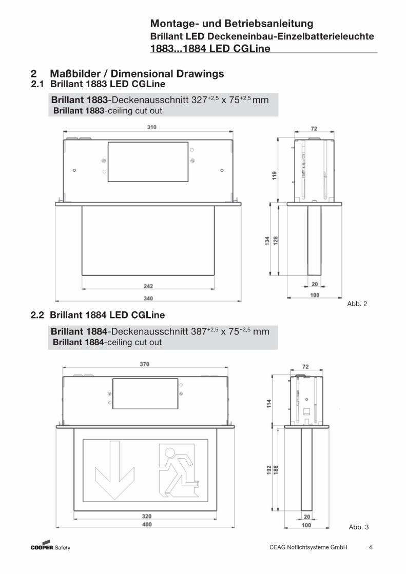
2 Maßbilder / Dimensional Drawings2.1 Brillant 1883 LED CGLine
Brillant 1883-Deckenausschnitt 327+2,5 x 75+2,5 mm Brillant 1883-ceiling cut out
2.2 Brillant 1884 LED CGLine
Brillant 1884-Deckenausschnitt 387+2,5 x 75+2,5 mm Brillant 1884-ceiling cut out
Abb. 3
Abb. 2
CEAG Notlichtsysteme GmbH 5
Montage- und BetriebsanleitungBrillant LED Deckeneinbau-Einzelbatterieleuchte1883...1884 LED CGLine
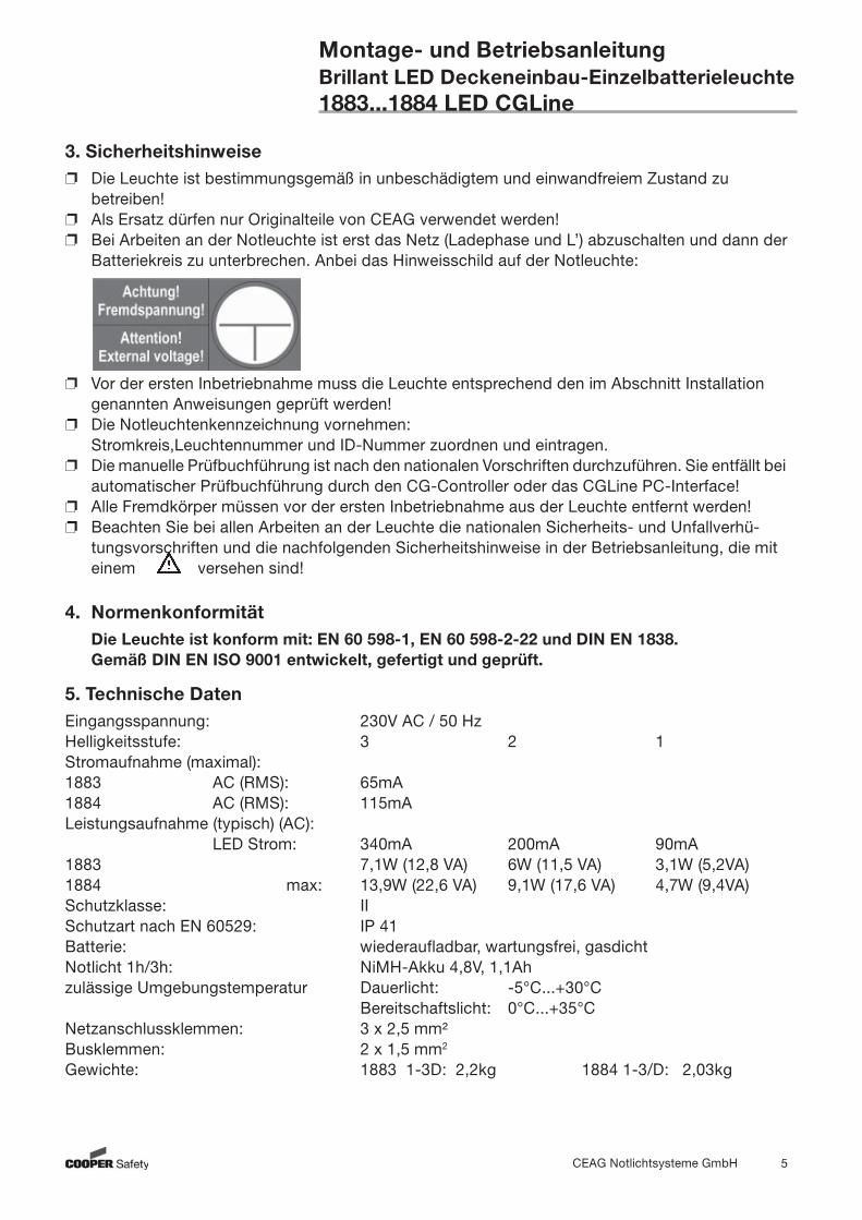
3. Sicherheitshinweise Die Leuchte ist bestim mungs gemäß in unbeschädigtem und einwandfreiem Zustand zu
betreiben! Als Ersatz dürfen nur Originalteile von CEAG verwendet werden! Bei Arbeiten an der Notleuchte ist erst das Netz (Ladephase und L’) abzuschalten und dann der
Batteriekreis zu unterbrechen. Anbei das Hinweisschild auf der Notleuchte:
Vor der ersten Inbetriebnahme muss die Leuchte entsprechend den im Abschnitt Installation genannten Anweisungen geprüft werden!
Die Notleuchtenkenn zeich nung vornehmen: Stromkreis,Leuchtennummer und ID-Nummer zuordnen und eintragen.
Die manuelle Prüfbuchführung ist nach den nationalen Vorschriften durchzuführen. Sie entfällt bei automatischer Prüfbuchführung durch den CG-Controller oder das CGLine PC-Interface!
Alle Fremdkörper müssen vor der ersten Inbetriebnahme aus der Leuchte entfernt werden! Beachten Sie bei allen Ar beiten an der Leuchte die nationalen Sicherheits- und Unfallverhü-
tungsvorschriften und die nachfolgenden Sicherheitshinweise in der Betriebsanleitung, die mit einem versehen sind!
4. Normenkonformität Die Leuchte ist konform mit: EN 60 598-1, EN 60 598-2-22 und DIN EN 1838. Gemäß DIN EN ISO 9001 entwickelt, gefertigt und geprüft.
5. Technische DatenEingangsspannung: 230V AC / 50 Hz Helligkeitsstufe: 3 2 1Stromaufnahme (maximal): 1883 AC (RMS): 65mA 1884 AC (RMS): 115mA Leistungsauf nahme (typisch) (AC): LED Strom: 340mA 200mA 90mA1883 7,1W (12,8 VA) 6W (11,5 VA) 3,1W (5,2VA) 1884 max: 13,9W (22,6 VA) 9,1W (17,6 VA) 4,7W (9,4VA)Schutzklasse: IISchutzart nach EN 60529: IP 41Batterie: wiederaufladbar, wartungsfrei, gasdichtNotlicht 1h/3h: NiMH-Akku 4,8V, 1,1Ahzulässige Umgebungstemperatur Dauerlicht: -5°C...+30°C Bereitschaftslicht: 0°C...+35°CNetzanschlussklemmen: 3 x 2,5 mm²Busklemmen: 2 x 1,5 mm2
Gewichte: 1883 1-3D: 2,2kg 1884 1-3/D: 2,03kg
CEAG Notlichtsysteme GmbH 6
Montage- und BetriebsanleitungBrillant LED Deckeneinbau-Einzelbatterieleuchte1883...1884 LED CGLine
5.1 Kurzbeschreibung / Verwendungsbereich Die Rettungszeichenleuchten Brillant 1883...1884 LED CGLine sind als Einzelbatterieleuchten in Installationen nach EN 50172, DIN VDE 0100-718 und E DIN VDE 0108-100 geeignet. Die Einzelbatterieleuchten CGLine können mit dem CEAG CG-Controller CGLine 400 oder dem CGLine PC-Interface über eine Busleitung zentral überwacht werden.
6. Installation / Inbetriebnahme
Halten Sie die für das Errichten und Betreiben von elektrischen Betriebsmitteln geltenden Sicherheitsvorschriften und das Gerätesicherheitsgesetz sowie die allgemein anerkannten Regeln der Technik ein!
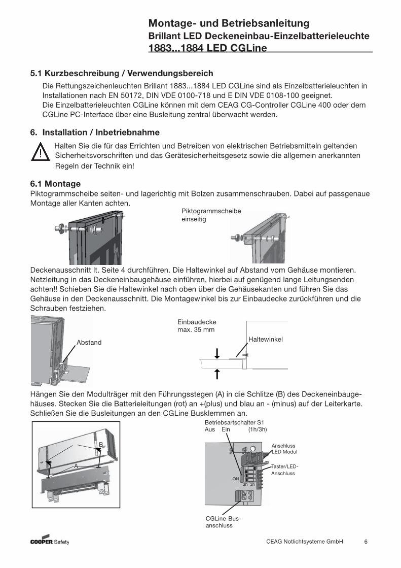
6.1 Montage Piktogrammscheibe seiten- und lagerichtig mit Bolzen zusammenschrauben. Dabei auf passgenaue Montage aller Kanten achten.
Deckenausschnitt lt. Seite 4 durchführen. Die Haltewinkel auf Abstand vom Gehäuse montieren.Netzleitung in das Deckeneinbaugehäuse einführen, hierbei auf genügend lange Leitungsenden achten!! Schieben Sie die Haltewinkel nach oben über die Gehäusekanten und führen Sie das Gehäuse in den Deckenausschnitt. Die Montagewinkel bis zur Einbaudecke zurückführen und die Schrauben festziehen.
Hängen Sie den Modulträger mit den Führungsstegen (A) in die Schlitze (B) des Deckeneinbauge-häuses. Stecken Sie die Batterieleitungen (rot) an +(plus) und blau an - (minus) auf der Leiterkarte. Schließen Sie die Busleitungen an den CGLine Busklemmen an.
Taster/LED-Anschluss
Betriebsartschalter S1Aus Ein (1h/3h)
CGLine-Bus-anschluss
3h 1hON
AnschlussLED Modul
Piktogrammscheibeeinseitig
Abstand
Einbaudecke max. 35 mm
Haltewinkel
B
A
CEAG Notlichtsysteme GmbH 7
Montage- und BetriebsanleitungBrillant LED Deckeneinbau-Einzelbatterieleuchte1883...1884 LED CGLine
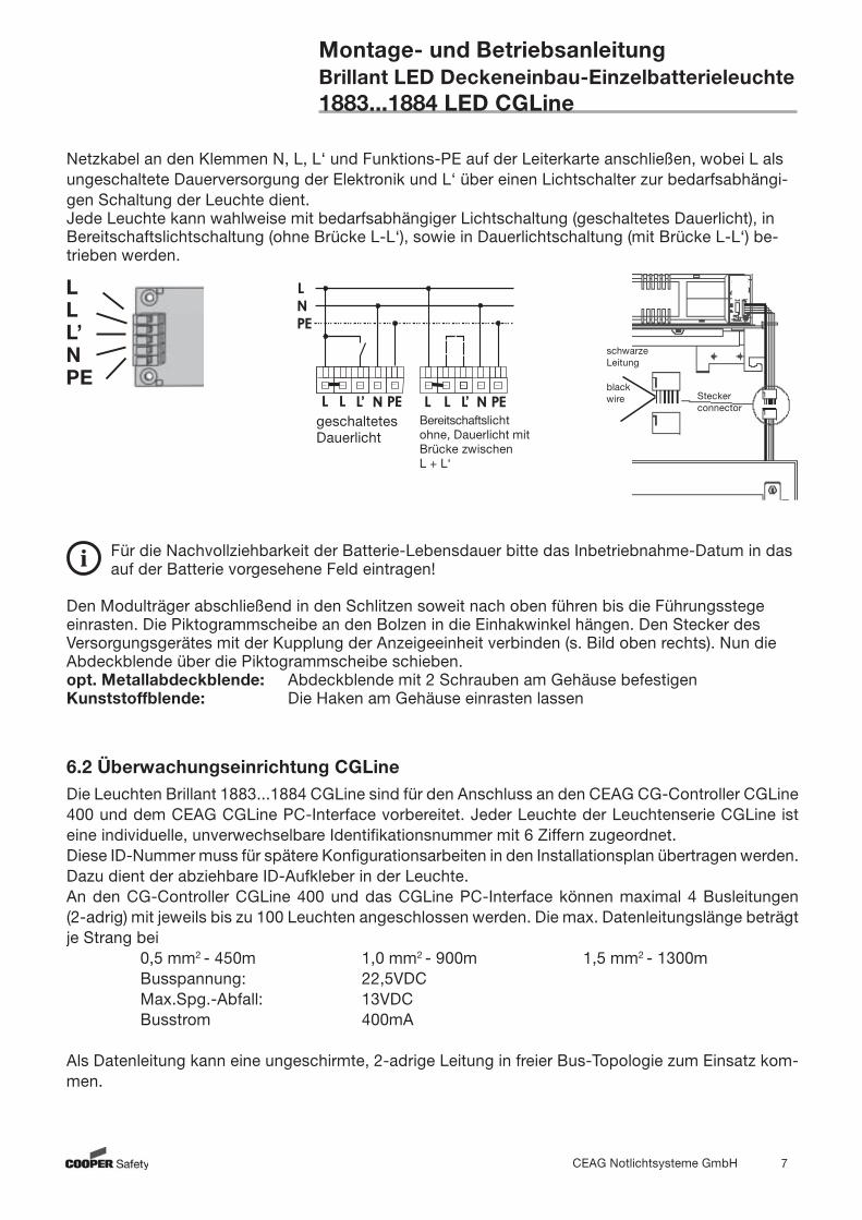
Netzkabel an den Klemmen N, L, L‘ und Funktions-PE auf der Leiterkarte anschließen, wobei L als ungeschaltete Dauerversorgung der Elektronik und L‘ über einen Lichtschalter zur bedarfsabhängi-gen Schaltung der Leuchte dient. Jede Leuchte kann wahlweise mit bedarfsabhängiger Lichtschaltung (geschaltetes Dauerlicht), in Bereitschaftslichtschaltung (ohne Brücke L-L‘), sowie in Dauerlichtschaltung (mit Brücke L-L‘) be-trieben werden.
Für die Nachvollziehbarkeit der Batterie-Lebensdauer bitte das Inbetriebnahme-Datum in das auf der Batterie vorgesehene Feld eintragen!
Den Modulträger abschließend in den Schlitzen soweit nach oben führen bis die Führungsstege einrasten. Die Piktogrammscheibe an den Bolzen in die Einhakwinkel hängen. Den Stecker des Versorgungsgerätes mit der Kupplung der Anzeigeeinheit verbinden (s. Bild oben rechts). Nun die Abdeckblende über die Piktogrammscheibe schieben. opt. Metallabdeckblende: Abdeckblende mit 2 Schrauben am Gehäuse befestigenKunststoffblende: Die Haken am Gehäuse einrasten lassen
6.2 Überwachungseinrichtung CGLineDie Leuchten Brillant 1883...1884 CGLine sind für den Anschluss an den CEAG CG-Controller CGLine 400 und dem CEAG CGLine PC-Interface vorbereitet. Jeder Leuchte der Leuchtenserie CGLine ist eine individuelle, unverwechselbare Identifikationsnummer mit 6 Ziffern zugeordnet.Diese ID-Nummer muss für spätere Konfigurationsarbeiten in den Installationsplan übertragen werden. Dazu dient der abziehbare ID-Aufkleber in der Leuchte.An den CG-Controller CGLine 400 und das CGLine PC-Interface können maximal 4 Busleitungen (2-adrig) mit jeweils bis zu 100 Leuchten angeschlossen werden. Die max. Datenleitungslänge beträgt je Strang bei 0,5 mm2 - 450m 1,0 mm2 - 900m 1,5 mm2 - 1300m Busspannung: 22,5VDC Max.Spg.-Abfall: 13VDC Busstrom 400mA
Als Datenleitung kann eine ungeschirmte, 2-adrige Leitung in freier Bus-Topologie zum Einsatz kom-men.
schwarze Leitung
blackwire Stecker
connector
1
LLL’NPE
geschaltetesDauerlicht
Bereitschaftslicht ohne, Dauerlicht mit Brücke zwischen L + L‘
CEAG Notlichtsysteme GmbH 8
Montage- und BetriebsanleitungBrillant LED Deckeneinbau-Einzelbatterieleuchte1883...1884 LED CGLine
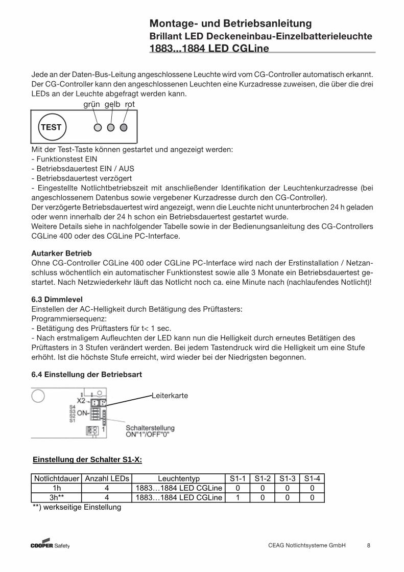
Jede an der Daten-Bus-Leitung angeschlossene Leuchte wird vom CG-Controller automatisch erkannt. Der CG-Controller kann den angeschlossenen Leuchten eine Kurzadresse zuweisen, die über die drei LEDs an der Leuchte abgefragt werden kann.
Mit der Test-Taste können gestartet und angezeigt werden:- Funktionstest EIN- Betriebsdauertest EIN / AUS- Betriebsdauertest verzögert- Eingestellte Notlichtbetriebszeit mit anschließender Identifikation der Leuchtenkurzadresse (bei angeschlossenem Datenbus sowie vergebener Kurzadresse durch den CG-Controller).Der verzögerte Betriebsdauertest wird angezeigt, wenn die Leuchte nicht ununterbrochen 24 h geladen oder wenn innerhalb der 24 h schon ein Betriebsdauertest gestartet wurde.Weitere Details siehe in nachfolgender Tabelle sowie in der Bedienungsanleitung des CG-Controllers CGLine 400 oder des CGLine PC-Interface.
Autarker BetriebOhne CG-Controller CGLine 400 oder CGLine PC-Interface wird nach der Erstinstallation / Netzan-schluss wöchentlich ein automatischer Funktionstest sowie alle 3 Monate ein Betriebsdauertest ge-startet. Nach Netzwiederkehr läuft das Notlicht noch ca. eine Minute nach (nachlaufendes Notlicht)!
6.3 DimmlevelEinstellen der AC-Helligkeit durch Betätigung des Prüftasters:Programmiersequenz:- Betätigung des Prüftasters für t< 1 sec.- Nach erstmaligem Aufleuchten der LED kann nun die Helligkeit durch erneutes Betätigen des Prüftasters in 3 Stufen verändert werden. Bei jedem Tastendruck wird die Helligkeit um eine Stufe erhöht. Ist die höchste Stufe erreicht, wird wieder bei der Niedrigsten begonnen.
6.4 Einstellung der Betriebsart
TEST
grün gelb rot
Einstellung der Schalter S1-X:
Notlichtdauer Anzahl LEDs Leuchtentyp S1-1 S1-2 S1-3 S1-41h 4 1883…1884 LED CGLine 0 0 0 0
3h** 4 1883…1884 LED CGLine 1 0 0 0**) werkseitige Einstellung
Leiterkarte
CEAG Notlichtsysteme GmbH 9
Montage- und BetriebsanleitungBrillant LED Deckeneinbau-Einzelbatterieleuchte1883...1884 LED CGLine
6.4 Kontroll-LEDs
Technische Änderungen vorbehalten!
7. Inspektion/Wartung/InstandhaltungHalten Sie die für die Inspektion,Wartung und Instandhaltung von elektrischen Betriebsmitteln geltenden Bestimmungen ein!
8. Entsorgung / RecyclingBeachten Sie bei der Entsorgung defekter Geräte die gültigen Vorschriften für Recycling und Entsor-gung. Kunststoffteile sind mit entsprechenden Symbolen gekennzeichnet. Der in der Leuchte eingebaute NiMh-Akkus ist - entsprechend der EU-Richtline 2006/66/ EG - beim Wechsel an den Vertreiber oder an einen zugelassenen Entsorger zurückzu- geben und darf nicht selbst entsorgt werden!
Im Fall von Rücksendungen benötigen Sie von uns eine RMA - Nummer. Entnehmen Sie bitte weitere Infos hierzu unserer Internetseite www.ceag.de!
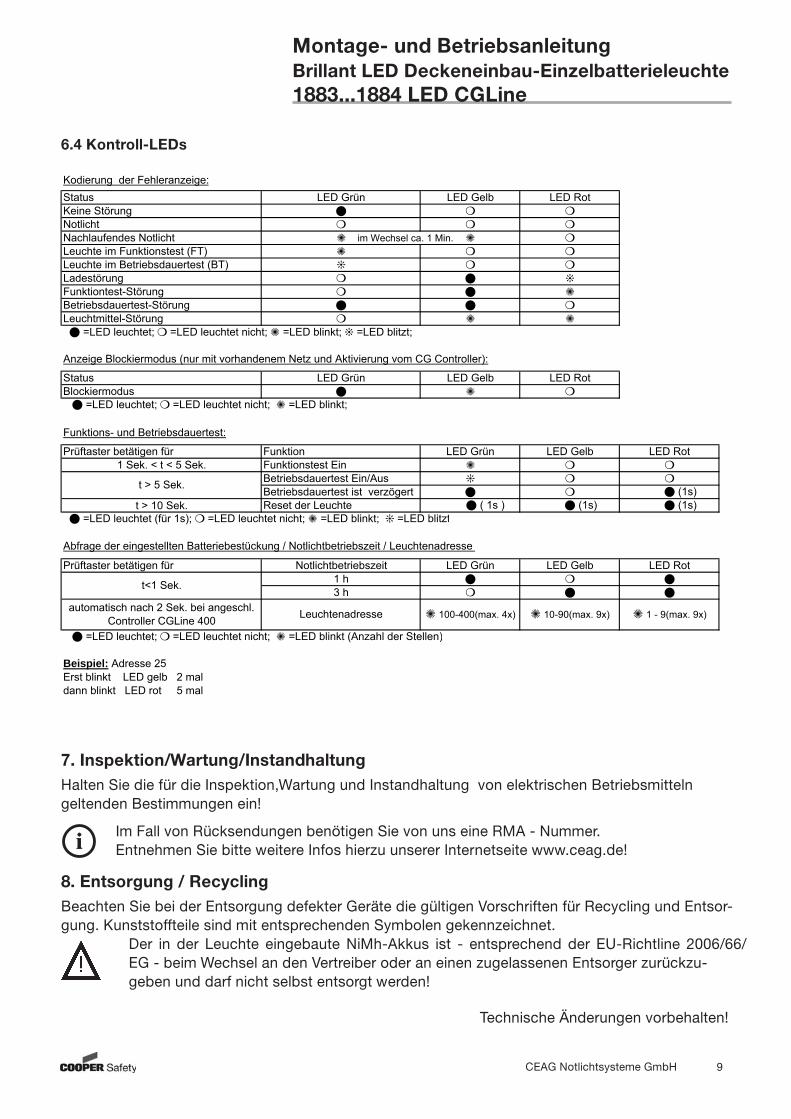
Kodierung der Fehleranzeige:Status LED Grün LED Gelb LED RotKeine StörungNotlichtNachlaufendes NotlichtLeuchte im Funktionstest (FT)Leuchte im Betriebsdauertest (BT)LadestörungFunktiontest-Störung Betriebsdauertest-StörungLeuchtmittel-Störung
Anzeige Blockiermodus (nur mit vorhandenem Netz und Aktivierung vom CG Controller):
Status LED Grün LED Gelb LED RotBlockiermodus =LED leuchtet; =LED leuchtet nicht; =LED blinkt;
Funktions- und Betriebsdauertest:
Prüftaster betätigen für Funktion LED Grün LED Gelb LED Rot1 Sek. < t < 5 Sek. Funktionstest Ein
Betriebsdauertest Ein/AusBetriebsdauertest ist verzögert (1s)
t > 10 Sek. Reset der Leuchte ( 1s ) (1s) (1s) =LED leuchtet (für 1s); =LED leuchtet nicht; =LED blinkt; =LED blitzt
Abfrage der eingestellten Batteriebestückung / Notlichtbetriebszeit / Leuchtenadresse
Prüftaster betätigen für Notlichtbetriebszeit LED Grün LED Gelb LED Rot1 h3 h
=LED leuchtet; =LED leuchtet nicht; =LED blinkt (Anzahl der Stellen)
Beispiel: Adresse 25Erst blinkt LED gelb 2 maldann blinkt LED rot 5 mal
im Wechsel ca. 1 Min.
100-400(max. 4x) 10-90(max. 9x) 1 - 9(max. 9x)
=LED leuchtet; =LED leuchtet nicht; =LED blinkt; =LED blitzt;
t > 5 Sek.
t<1 Sek.
Leuchtenadresseautomatisch nach 2 Sek. bei angeschl. Controller CGLine 400

CEAG Notlichtsysteme GmbH 10
Operating InstructionsSelf contained LED luminaire for ceiling mounting1883...1884 LED CGLine
3. Safety Notes The luminaire shall only be used for its intended purpose and in an indamaged and perfect
condition! Only genuine CEAG spare parts may be used for replacement and repair! When working on the emergency luminaire first cut off mains (charging phase and L’) and inter-
rupt battery operation. Enclosed indication label on the emergency luminaire:
Prior to its initial operation, the luminaire will have to be checked in accordance with the instruc- tions as per section ‘Installation’!
Carry out the marking of the emergency luminaire: Assign the circuit, the luminaire no. and ID no. and enter them.
The manual log book shall be performed in compliance with the national regulations. It is not applicable by automatical log book with the CG-Controller CGLine or the CGLine PC-Interface!
Any foreign matter shall be removed from the luminaire prior to its initial operation! Observe the national safety rules and regulations for prevention of accidents as well as the safety
instructions included in these operating instructions marked with !
4. Conformity to standards Conforms to: EN 60 598-1, EN 60 598-2-22 and DIN EN 1838. Developed, manufactured and tested in accordance with DIN EN ISO 9001.
5. Technical DataInput voltage: 230/240V AC / 50 HzBrightness-Level: 3 2 1Current consumption (maximum): 1883 AC (RMS): 65mA 1884 AC (RMS): 115mA LED current: 340mA 200mA 90mAPower consumption (typical) (AC) 1883 7,1W (12,8 VA) 6W (11,5 VA) 3,1W (5,2VA)1884 max: 13,9W (22,6 VA) 9,1W (17,6 VA) 4,7W (9,4VA)Insulation class: IIDegree of protection acc. to EN 60529: IP 41Battery: gas-tight, reloadable, maintenance-free1h/3h: NiMH-Accu 4,8V, 1,1AhAdmissible amb. temperature Maintained Light: -5°C...+30°C Non Maintained Light: 0°C...+35°CSupply terminals: 3 x 2,5 mm²Bus terminals: 2 x 1,5 mm2
Weight: 1883 1-3/D: 2,2kg 1884 1-3/D: 2,03kg

CEAG Notlichtsysteme GmbH 11
Operating InstructionsSelf contained LED luminaire for ceiling mounting1883...1884 LED CGLine
5.1 Brief description / Scope of applicationAs a self contained luminaire the Brillant 1883...1884 LED CGLine emergency luminaire is suitable for installations acc. to EN 50172, DIN VDE 0100-718 and E DIN VDE 0108-100. With the CEAG CG-Controller CGLine 400 or the CGLine PC-Interface the self-contained luminaires can be monito-red centrally via a bus cable.
6. Installation / Operation
For the mounting and operation of electrical apparatus, the respective national safety regulations as well as the general rules of engineering will have to be observed!
6.1 Mounting Mount the pictogram panel true sided and in correct position with the bolts. While mounting take care that the pictogram panel suite together!
For the ceiling cut-out see dimensions on page 4. Mount the holding angles. Insert the mains cable into the recessed ceiling mounting enclosure and ensure to keep long enough wiring ends!!Push the holding angles upwards via the enclosure and insert the enclosure into the ceiling cut-out. Push the mounting angles back to the ceiling and tighten the screws.
Fasten the module carrier (A) in the slits (B) of the ceiling mounting enclosure. Connect the battery wire (red) to + (plus) and blue to - (minus) on the printed board. Connect the bus cables to the CG-Line bus-terminals.
legend panel single-sided
DistanceMounting ceilingmax. 35 mm
Holding angle
B
A Button/
LED-con-nection
Operation mode switch S1OFF ON (1h/3h)
CGLine-Bus connection
ConnectionLED Module
3h 1hON
CEAG Notlichtsysteme GmbH 12
Operating InstructionsSelf contained LED luminaire for ceiling mounting1883...1884 LED CGLine
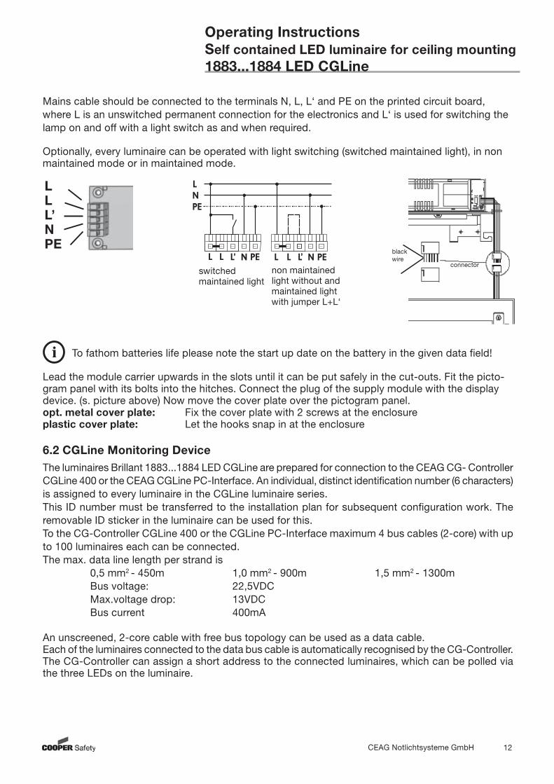
Mains cable should be connected to the terminals N, L, L‘ and PE on the printed circuit board, where L is an unswitched permanent connection for the electronics and L‘ is used for switching the lamp on and off with a light switch as and when required. Optionally, every luminaire can be operated with light switching (switched maintained light), in non maintained mode or in maintained mode.
To fathom batteries life please note the start up date on the battery in the given data field!
Lead the module carrier upwards in the slots until it can be put safely in the cut-outs. Fit the picto-gram panel with its bolts into the hitches. Connect the plug of the supply module with the display device. (s. picture above) Now move the cover plate over the pictogram panel. opt. metal cover plate: Fix the cover plate with 2 screws at the enclosureplastic cover plate: Let the hooks snap in at the enclosure
6.2 CGLine Monitoring DeviceThe luminaires Brillant 1883...1884 LED CGLine are prepared for connection to the CEAG CG- Controller CGLine 400 or the CEAG CGLine PC-Interface. An individual, distinct identification number (6 characters) is assigned to every luminaire in the CGLine luminaire series.This ID number must be transferred to the installation plan for subsequent configuration work. The removable ID sticker in the luminaire can be used for this.To the CG-Controller CGLine 400 or the CGLine PC-Interface maximum 4 bus cables (2-core) with up to 100 luminaires each can be connected. The max. data line length per strand is 0,5 mm2 - 450m 1,0 mm2 - 900m 1,5 mm2 - 1300m Bus voltage: 22,5VDC Max.voltage drop: 13VDC Bus current 400mA
An unscreened, 2-core cable with free bus topology can be used as a data cable.Each of the luminaires connected to the data bus cable is automatically recognised by the CG-Controller. The CG-Controller can assign a short address to the connected luminaires, which can be polled via the three LEDs on the luminaire.
blackwire
connector
1
LLL’NPE
switched maintained light
non maintained light without and maintained light with jumper L+L‘
CEAG Notlichtsysteme GmbH 13
Operating InstructionsSelf contained LED luminaire for ceiling mounting1883...1884 LED CGLine
The following can be started and displayed with the test-button:- function test ON- duration test ON/OFF- duration test delayed- settings of the emergencylight operating time with subsequent identification of the luminaire short address (when data bus is connected and the CG-Controller has issued short addresses).The delayed duration test is displayed if the luminaire is not charged without interruption for 24h or if an duration test is started within the 24h.For further details see the operating manual of the CG-Controllers CGLine 400 or the CGLine PC-Interface.
Autarkic operationWithout the CG-Controller CGLine or the CEAG CGLine PC-Interface the luminaire starts after the initial installation/mains connection the function test weekly and a duration test every three months.After mains returns the emergency operation will stay for approx. 1 minute (delay on mains return)!
6.3 Dim-LevelSetting the AC-lightness by using the test button- Push the test-button for t < 1 sec.- After the first flash of the LED the lightness can be changed by pushing the button again in 3 steps. Every push of the button raises the lightness for 1 step. If the hightest step is reached it begins again with the lowest.
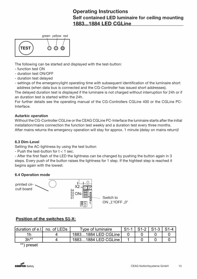
6.4 Operation mode
TEST
green yellow red
Switch toON „1“/OFF „0“
Position of the switches S1-X:
duration of e.l. no. of LEDs Type of luminaire S1-1 S1-2 S1-3 S1-41h 4 1883…1884 LED CGLine 0 0 0 0
3h** 4 1883…1884 LED CGLine 1 0 0 0**) preset
printed cir-cuit board
CEAG Notlichtsysteme GmbH 14
Operating InstructionsSelf contained LED luminaire for ceiling mounting1883...1884 LED CGLine
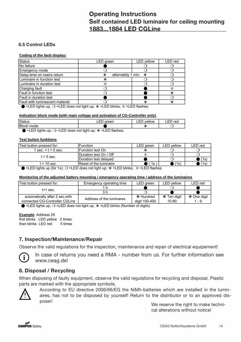
6.5 Control LEDs
We reserve the right to make techni-cal alterations without notice!
7. Inspection/Maintenance/RepairObserve the valid regulations for the inspection, maintenance and repair of electrical equipement!
8. Disposal / RecyclingWhen disposing of faulty equipment, observe the valid regulations for recycling and disposal. Plastic parts are marked with the appropriate symbols. According to EU directive 2006/66/EG the NiMh-batteries which are installed in the lumin- aires, has not to be disposed by yourself! Return to the distributor or to an approved dis- poser!
In case of returns you need a RMA - number from us. For further information see www.ceag.de!
Coding of the fault display:Status LED green LED yellow LED redNo failureEmergency modeDelay-time on mains returnLuminaire in function testLuminaire in duration testCharging faultFault in function testFault in duration testFault with luminescent material
Indication block mode (with main voltage and activation of CG-Controller only)Status LED green LED yellow LED redBlock mode =LED lights up; =LED does not light up; =LED flashes;
Test button funktionsTest button pressed for: Function LED green LED yellow LED red
1 sec. < t < 5 sec. Function test OnDuration test On / OffDuration test delayed (1s)
t > 10 sec. Reset of the luminaire ( 1s ) (1s) (1s) =LED lights up (für 1s); =LED does not light up; =LED blinks; =LED flashes
Monitoring of the adjusted battery mounting / emergency operating time / address of the luminairesTest button pressed for: Emergency operating time LED green LED yellow LED red
1 h3 h
Example: Address 25first blinks LED yellow 2 timesthan blinks LED red 5 times
=LED lights up; =LED does not light up; =LED blinks (Number of digits)
Ten digit 10-90
One digit 1 - 9
automatically after 2 sec.with connected CG-Controller CGLine
alternately 1 min.
Hundred digit 100-400
=LED lights up; =LED does not light up; =LED blinks; =LED flashes;
t > 5 sec.
t<1 sec.
Address of the luminares
CEAG Notlichtsysteme GmbH 15
Operating InstructionsSelf contained LED luminaire for ceiling mounting1883...1884 LED CGLine

400 71 860 093/xxx/07.08/WK