Embed Size (px)
Citation preview
MONTAGGIOE REGOLAZIONI
ASSEMBLY ANDADJUSTMENTS
MONTAGE UNDREGULIERUNG
18
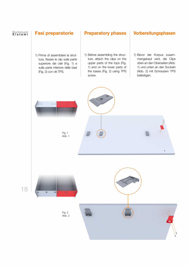
Fasi preparatorie
1) Prima di assemblare la strut-tura, fissare le clip sulla parte superiore dei cieli (Fig. 1) e sulla parte inferiore delle basi (Fig. 2) con viti TPS.
VorbereitungsphasenPreparatory phases
1) Bevor der Korpus zusam-mengebaut wird, die Clips oben an den Oberseiten (Abb. 1) und unten an den Sockeln (Abb. 2) mit Schrauben TPS befestigen.
1) Before assembling the struc-ture, attach the clips on the upper parts of the tops (Fig. 1) and on the lower parts of the bases (Fig. 2) using TPS screw.
Fig. 1 Abb. 1
Fig. 2Abb. 2
19
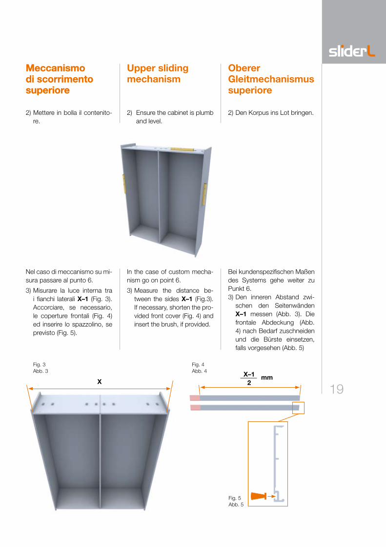
Nel caso di meccanismo su mi-sura passare al punto 6.
3) Misurare la luce interna tra i fianchi laterali X–1 (Fig. 3). Accorciare, se necessario, le coperture frontali (Fig. 4) ed inserire lo spazzolino, se previsto (Fig. 5).
Meccanismo di scorrimento superiore
2) Mettere in bolla il contenito-re.
Oberer Gleitmechanismus superiore
Upper sliding mechanism
Bei kundenspezifischen Maßen des Systems gehe weiter zu Punkt 6.3) Den inneren Abstand zwi-
schen den Seitenwänden X–1 messen (Abb. 3). Die frontale Abdeckung (Abb. 4) nach Bedarf zuschneiden und die Bürste einsetzen, falls vorgesehen (Abb. 5)
In the case of custom mecha-nism go on point 6.
3) Measure the distance be-tween the sides X–1 (Fig.3). If necessary, shorten the pro-vided front cover (Fig. 4) and insert the brush, if provided.
2) Den Korpus ins Lot bringen.
Fig. 3 Abb. 3
Fig. 4 Abb. 4
2) Ensure the cabinet is plumb and level.
Fig. 5Abb. 5
XX–1
2mm
Meccanismo di scorrimento superiore
20
Meccanismo di scorrimento superiore
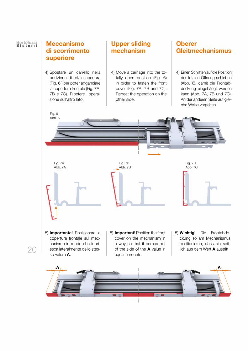
4) Spostare un carrello nella posizione di totale apertura (Fig. 6 ) per poter agganciare la copertura frontale (Fig. 7A, 7B e 7C). Ripetere l’opera-zione sull’altro lato.
5) Importante! Posizionare la copertura frontale sul mec-canismo in modo che fuori-esca lateralmente dello stes-so valore A.
Oberer Gleitmechanismus
Upper sliding mechanism
4) Einen Schlitten auf die Position der totalen Öffnung schieben (Abb. 6), damit die Frontab-deckung eingehängt werden kann (Abb. 7A, 7B und 7C). An der anderen Seite auf glei-che Weise vorgehen.
5) Important! Position the front cover on the mechanism in a way so that it comes out of the side of the A value in equal amounts.
5) Wichtig! Die Frontabde-ckung so am Mechanismus positionieren, dass sie seit-lich aus dem Wert A austritt.
Fig. 7AAbb. 7A
Fig. 7BAbb. 7B
Fig. 7CAbb. 7C
_._
._._
._._
._
Fig. 6Abb. 6
4) Move a carriage into the to-tally open position (Fig. 6) in order to fasten the front cover (Fig. 7A, 7B and 7C). Repeat the operation on the other side.
A A
_._
._._
._._
.__
._._
._._
._._
21
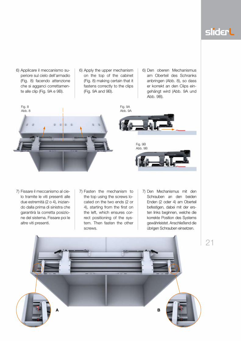
6) Applicare il meccanismo su-periore sul cielo dell’armadio (Fig. 8) facendo attenzione che si agganci correttamen-te alle clip (Fig. 9A e 9B).
7) Fissare il meccanismo al cie-lo tramite le viti presenti alle due estremità (2 o 4), inizian-do dalla prima di sinistra che garantirà la corretta posizio-ne del sistema. Fissare poi le altre viti presenti.
_._
._._
._._
._
A B
6) Apply the upper mechanism on the top of the cabinet (Fig. 8) making certain that it fastens correctly to the clips (Fig. 9A and 9B).
6) Den oberen Mechanismus am Oberteil des Schranks anbringen (Abb. 8), so dass er korrekt an den Clips ein-gehängt wird (Abb. 9A und Abb. 9B).
7) Fasten the mechanism to the top using the screws lo-cated on the two ends (2 or 4), starting from the first on the left, which ensures cor-rect positioning of the sys-tem. Then fasten the other screws.
7) Den Mechanismus mit den Schrauben an den beiden Enden (2 oder 4) am Oberteil befestigen, dabei mit der ers-ten links beginnen, welche die korrekte Position des Systems gewährleistet. Anschließend die übrigen Schrauben einsetzen.
Fig. 8Abb. 8
Fig. 9AAbb. 9A
Fig. 9BAbb. 9B
22
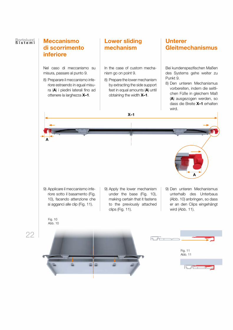
Meccanismo di scorrimento inferiore
Nel caso di meccanismo su misura, passare al punto 9.
8) Preparare il meccanismo infe-riore estraendo in egual misu-ra (A) i piedini laterali fino ad ottenere la larghezza X–1.
9) Applicare il meccanismo infe-riore sotto il basamento (Fig. 10), facendo attenzione che si agganci alle clip (Fig. 11).
Unterer Gleitmechanismus
Lower sliding mechanism
In the case of custom mecha-nism go on point 9.
8) Prepare the lower mechanism by extracting the side support feet in equal amounts (A) until obtaining the width X–1.
Bei kundenspezifischen Maßen des Systems gehe weiter zu Punkt 9. 8) Den unteren Mechanismus
vorbereiten, indem die seitli-chen Füße in gleichem Maß (A) ausgezogen werden, so dass die Breite X–1 erhalten wird.
9) Apply the lower mechanism under the base (Fig. 10), making certain that it fastens to the previously attached clips (Fig. 11).
9) Den unteren Mechanismus unterhalb des Unterbaus (Abb. 10) anbringen, so dass er an den Clips eingehängt wird (Abb. 11).
Fig. 10Abb. 10
Fig. 11Abb. 11
X–1
_._
._._
._._
._
_._
._._
._
A
A
23
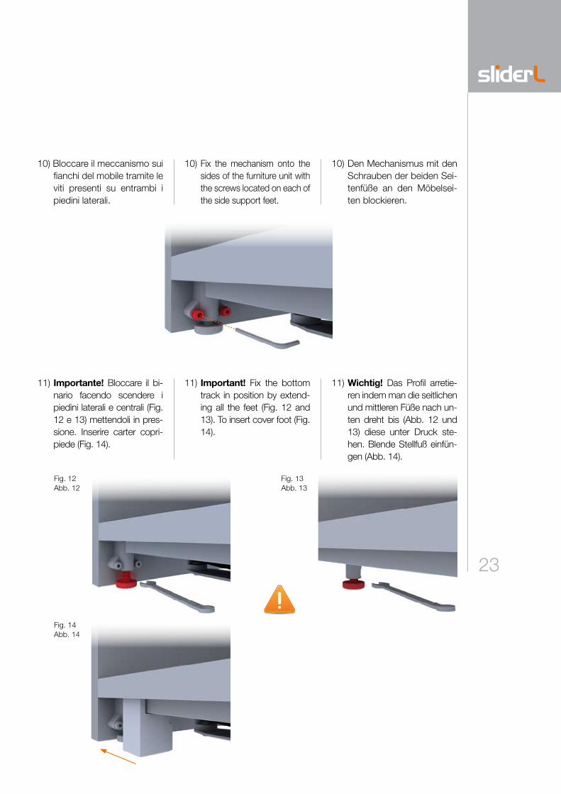
10) Bloccare il meccanismo sui fianchi del mobile tramite le viti presenti su entrambi i piedini laterali.
11) Importante! Bloccare il bi-nario facendo scendere i piedini laterali e centrali (Fig. 12 e 13) mettendoli in pres-sione. Inserire carter copri-piede (Fig. 14).
10) Fix the mechanism onto the sides of the furniture unit with the screws located on each of the side support feet.
10) Den Mechanismus mit den Schrauben der beiden Sei-tenfüße an den Möbelsei-ten blockieren.
11) Important! Fix the bottom track in position by extend-ing all the feet (Fig. 12 and 13). To insert cover foot (Fig. 14).
11) Wichtig! Das Profil arretie-ren indem man die seitlichen und mittleren Füße nach un-ten dreht bis (Abb. 12 und 13) diese unter Druck ste-hen. Blende Stellfuß einfün-gen (Abb. 14).
Fig. 12Abb. 12
Fig. 13Abb. 13
Fig. 14Abb. 14
2424
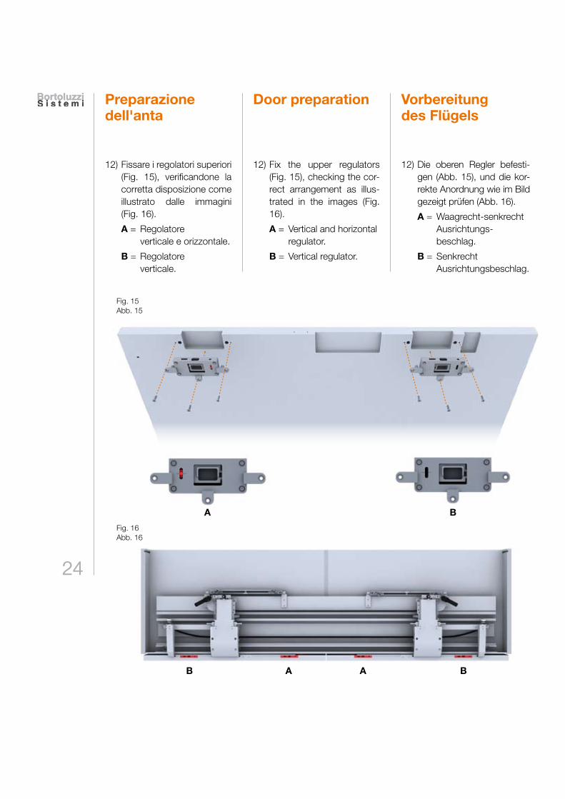
Preparazione dell'anta
12) Fissare i regolatori superiori (Fig. 15), verificandone la corretta disposizione come illustrato dalle immagini (Fig. 16).
A = Regolatore verticale e orizzontale.
B = Regolatore verticale.
Vorbereitung des Flügels
Door preparation
12) Fix the upper regulators (Fig. 15), checking the cor-rect arrangement as illus-trated in the images (Fig. 16).
A = Vertical and horizontal regulator.
B = Vertical regulator.
12) Die oberen Regler befesti-gen (Abb. 15), und die kor-rekte Anordnung wie im Bild gezeigt prüfen (Abb. 16).
A = Waagrecht-senkrecht Ausrichtungs-
beschlag.
B = Senkrecht Ausrichtungsbeschlag.
Fig. 15Abb. 15
Fig. 16Abb. 16
B
B B
A
A A
25
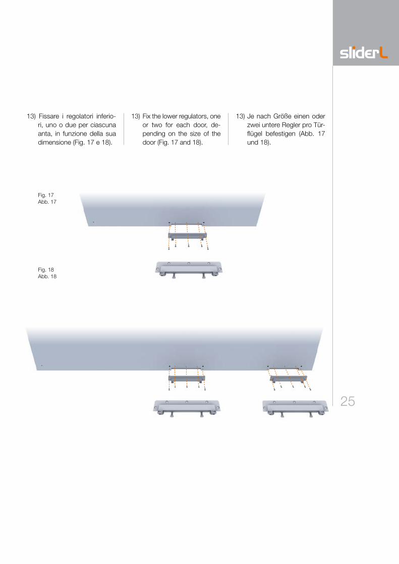
13) Fissare i regolatori inferio-ri, uno o due per ciascuna anta, in funzione della sua dimensione (Fig. 17 e 18).
13) Fix the lower regulators, one or two for each door, de-pending on the size of the door (Fig. 17 and 18).
13) Je nach Größe einen oder zwei untere Regler pro Tür-flügel befestigen (Abb. 17 und 18).
Fig. 17Abb. 17
Fig. 18Abb. 18
26
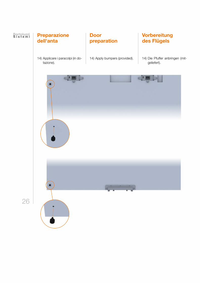
Preparazione dell'anta
14) Applicare i paracolpi (in do-tazione).
Vorbereitung des Flügels
Door preparation
14) Apply bumpers (provided). 14) Die Pfuffer anbringen (mit-geliefert).
27
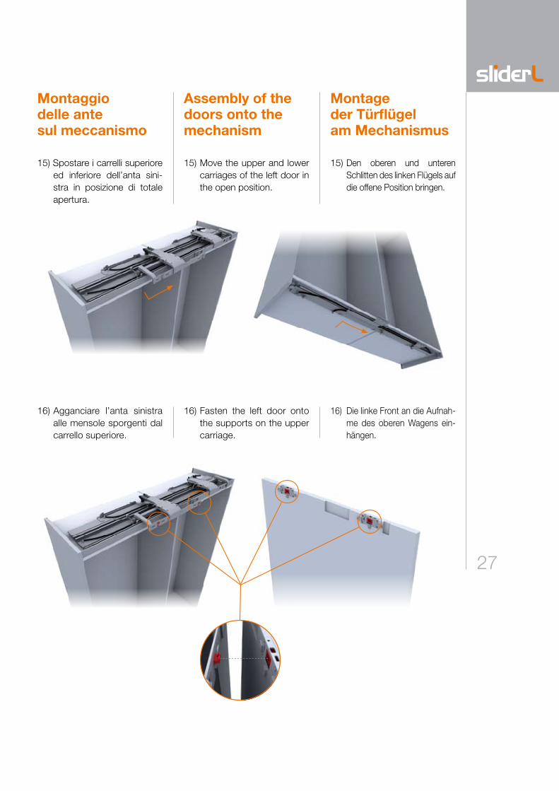
Montaggio delle ante sul meccanismo
15) Spostare i carrelli superiore ed inferiore dell’anta sini-stra in posizione di totale apertura.
16) Agganciare l’anta sinistra alle mensole sporgenti dal carrello superiore.
Montage der Türflügel am Mechanismus
Assembly of the doors onto the mechanism
15) Move the upper and lower carriages of the left door in the open position.
15) Den oberen und unteren Schlitten des linken Flügels auf die offene Position bringen.
16) Fasten the left door onto the supports on the upper carriage.
16) Die linke Front an die Aufnah-me des oberen Wagens ein-hängen.
28
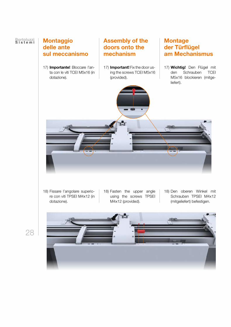
Assembly of the doors onto the mechanism
Montage der Türflügel am Mechanismus
17) Important! Fix the door us-ing the screws TCEI M5x16 (provided).
17) Wichtig! Den Flügel mit den Schrauben TCEI M5x16 blockieren (mitge-liefert).
Montaggio delle ante sul meccanismo
17) Importante! Bloccare l’an-ta con le viti TCEI M5x16 (in dotazione).
18) Fasten the upper angle using the screws TPSEI M4x12 (provided).
18) Den oberen Winkel mit Schrauben TPSEI M4x12 (mitgeliefert) befestigen.
18) Fissare l’angolare superio-re con viti TPSEI M4x12 (in dotazione).
29
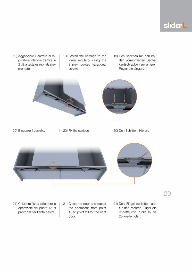
19) Fasten the carriage to the lower regulator using the 2 pre-mounted hexagonal screws.
19) Den Schlitten mit den bei-den vormontierten Sechs-kantschrauben am unteren Regler einhängen.
20) Fix the carriage. 20) Den Schlitten fixieren.
21) Close the door and repeat the operations from point 15 to point 20 for the right door.
21) Den Flügel schließen und für den rechten Flügel die Schritte von Punkt 15 bis 20 wiederholen.
19) Agganciare il carrello al re-golatore inferiore tramite le 2 viti a testa esagonale pre-montate.
20) Bloccare il carrello.
21) Chiudere l’anta e ripetere le operazioni dal punto 15 al punto 20 per l’anta destra.
30
Regolazioni
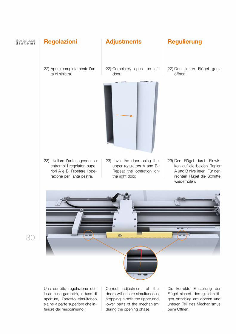
22) Aprire completamente l’an-ta di sinistra.
23) Livellare l’anta agendo su entrambi i regolatori supe-riori A e B. Ripetere l’ope-razione per l’anta destra.
Una corretta regolazione del-le ante ne garantirà, in fase di apertura, l’arresto simultaneo sia nella parte superiore che in-feriore del meccanismo.
Adjustments Regulierung
22) Completely open the left door.
22) Den linken Flügel ganz öffnen.
23) Level the door using the upper regulators A and B. Repeat the operation on the right door.
23) Den Flügel durch Einwir-ken auf die beiden Regler A und B nivellieren. Für den rechten Flügel die Schritte wiederholen.
Correct adjustment of the doors will ensure simultaneous stopping in both the upper and lower parts of the mechanism during the opening phase.
Die korrekte Einstellung der Flügel sichert den gleichzeiti-gen Anschlag am oberen und unteren Teil des Mechanismus beim Öffnen.
31
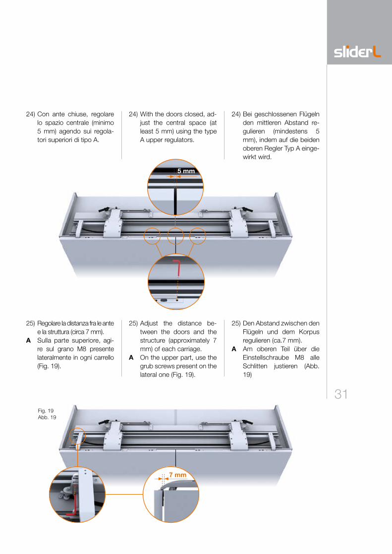
5 mm
7 mm
24) Con ante chiuse, regolare lo spazio centrale (minimo 5 mm) agendo sui regola-tori superiori di tipo A.
25) Regolare la distanza fra le ante e la struttura (circa 7 mm).
A Sulla parte superiore, agi-re sul grano M8 presente lateralmente in ogni carrello (Fig. 19).
24) Bei geschlossenen Flügeln den mittleren Abstand re-gulieren (mindestens 5 mm), indem auf die beiden oberen Regler Typ A einge-wirkt wird.
24) With the doors closed, ad-just the central space (at least 5 mm) using the type A upper regulators.
25) Adjust the distance be-tween the doors and the structure (approximately 7 mm) of each carriage.
A On the upper part, use the grub screws present on the lateral one (Fig. 19).
25) Den Abstand zwischen den Flügeln und dem Korpus regulieren (ca.7 mm).
A Am oberen Teil über die Einstellschraube M8 alle Schlitten justieren (Abb. 19)
Fig. 19Abb. 19
32
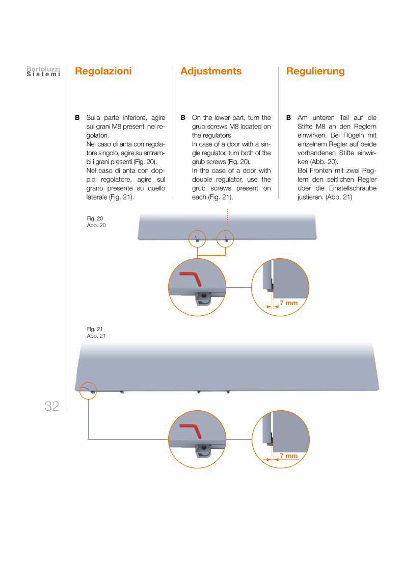
7 mm
7 mm
Regolazioni
B Sulla parte inferiore, agire sui grani M8 presenti nei re-golatori.
Nel caso di anta con regola-tore singolo, agire su entram-bi i grani presenti (Fig. 20).
Nel caso di anta con dop-pio regolatore, agire sul grano presente su quello laterale (Fig. 21).
RegulierungAdjustments
B Am unteren Teil auf die Stifte M8 an den Reglern einwirken. Bei Flügeln mit einzelnem Regler auf beide vorhandenen Stifte einwir-ken (Abb. 20).
Bei Fronten mit zwei Reg-lern den seitlichen Regler über die Einstellschraube justieren. (Abb. 21)
B On the lower part, turn the grub screws M8 located on the regulators.
In case of a door with a sin-gle regulator, turn both of the grub screws (Fig. 20).
In the case of a door with double regulator, use the grub screws present on each (Fig. 21).
Fig. 20Abb. 20
Fig. 21Abb. 21
33
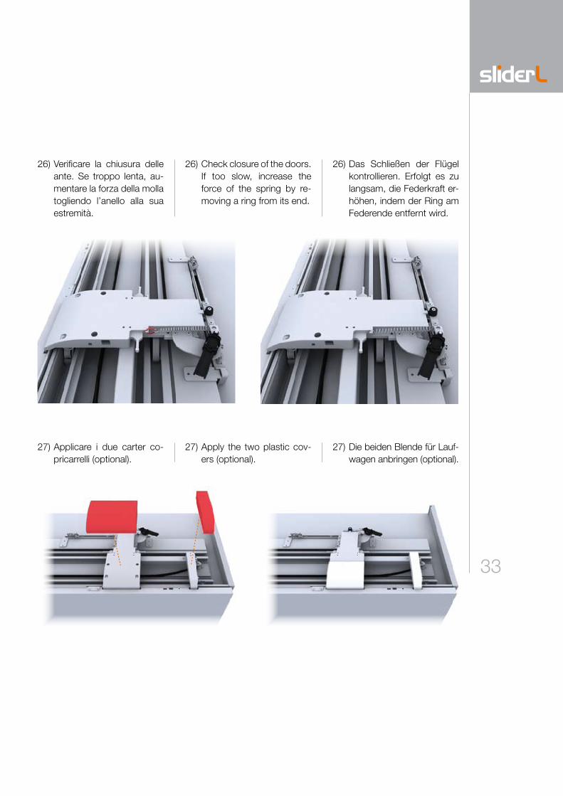
26) Verificare la chiusura delle ante. Se troppo lenta, au-mentare la forza della molla togliendo l’anello alla sua estremità.
27) Applicare i due carter co-pricarrelli (optional).
26) Das Schließen der Flügel kontrollieren. Erfolgt es zu langsam, die Federkraft er-höhen, indem der Ring am Federende entfernt wird.
27) Die beiden Blende für Lauf-wagen anbringen (optional).
26) Check closure of the doors. If too slow, increase the force of the spring by re-moving a ring from its end.
27) Apply the two plastic cov-ers (optional).
PuliziaLa pulizia dei componenti deve essere eseguita con acqua e sa-pone mediante un panno mor-bido. Evitare prodotti contenenti solventi e componenti abrasivi.
SmaltimentoUna volta dismesso, il prodotto e i suoi componenti non vanno dispersi nell’ambiente, ma con-feriti ai sistemi pubblici di smal-timento.
NotaL’Azienda produttrice si riserva il diritto di apportare modifiche tecniche senza preavviso.
CleaningCleaning the components must be executed using soap and water with a soft cloth. Avoid using products containing solvents and abrasive products.
DisposalThe products and its components must not be disposed of in the environment; for disposal, please use public disposal systems.
NoteThe manufacturer reserves the right to modify any product without prior notice.
ReinigungDie Reinigung der Teile muss mit Wasser, Seife und einem wei-chen Tuch erfolgen. Keine Pro-dukte mit Lösungsmitteln oder Schleifmittel verwenden.
EntsorgungDie Produkte und die Produkttei-le, die nicht mehr eingesetzt wer-den, sollen nicht in die Umwelt gelangen, sondern an den geeig-neten Stellen entsorgt werden.
HinweisDer Hersteller behält sich das Recht vor, Änderungen an den Produkten ohne vorherige An-kündigung vorzunehmen.