Embed Size (px)
Citation preview
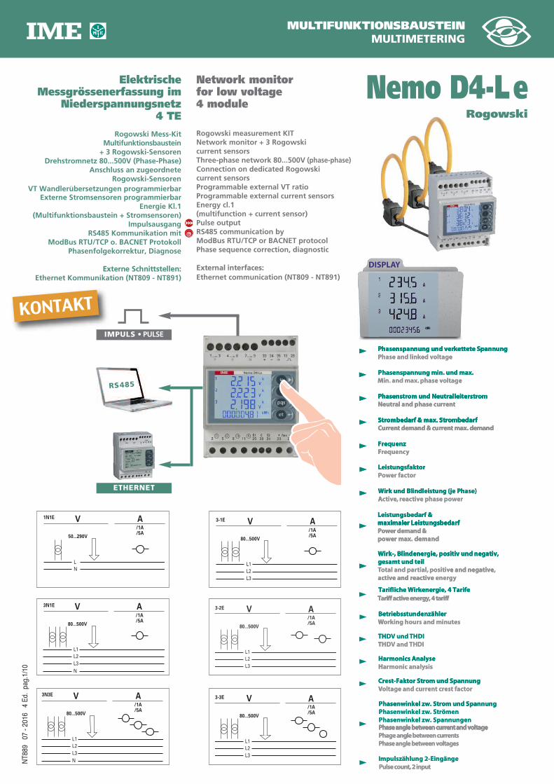
MULTIFUNKTIONSBAUSTEINMULTIMETERING
ElektrischeMessgrössenerfassung im
Niederspannungsnetz4 TE
Rogowski Mess-KitMultifunktionsbaustein+ 3 Rogowski-Sensoren
Drehstromnetz 80...500V (Phase-Phase)Anschluss an zugeordnete
Rogowski-SensorenVT Wandlerubersetzungen programmierbar
Externe Stromsensoren programmierbarEnergie Kl.1
(Multifunktionsbaustein + Stromsensoren)Impulsausgang
RS485 Kommunikation mitModBus RTU/TCP o. BACNET Protokoll
Phasenfolgekorrektur, Diagnose
Externe Schnittstellen:Ethernet Kommunikation (NT809 - NT891)
Network monitorfor low voltage4 module
Rogowski measurement KIT Network monitor + 3 Rogowskicurrent sensorsThree-phase network 80...500V (phase-phase)Connection on dedicated Rogowskicurrent sensorsProgrammable external VT ratioProgrammable external current sensors Energy cl.1(multifunction + current sensor)Pulse outputRS485 communication byModBus RTU/TCP or BACNET protocolPhase sequence correction, diagnostic
External interfaces:Ethernet communication (NT809 - NT891)
NT8
89
07 -
2016
4
Ed.
pag.
1/10
Nemo D4-Le
DISPLAY
Phasenspannung und verkettete SpannungPhase and linked voltage
Phasenstrom und Neutralleiterstrom Neutral and phase current
Strombedarf & max. StrombedarfCurrent demand & current max. demand
FrequenzFrequency
LeistungsfaktorPower factor
Wirk und Blindleistung (je Phase)Active, reactive phase power
Leistungsbedarf & maximaler Leistungsbedarf Power demand & power max. demand
Wirk-, Blindenergie, positiv und negativ,gesamt und teilTotal and partial, positive and negative, active and reactive energy
Tarifliche Wirkenergie, 4 TarifeTariff active energy, 4 tariff
BetriebsstundenzählerWorking hours and minutes
THDV und THDITHDV and THDI
Harmonics AnalyseHarmonic analysis
Phasenspannung min. und max.Min. and max. phase voltage
Crest-Faktor Strom und SpannungVoltage and current crest factor
Phasenwinkel zw. Strom und SpannungPhasenwinkel zw. StrömenPhasenwinkel zw. SpannungenPhase angle between current and voltagePhage angle between currentsPhase angle between voltages
Impulszählung 2-EingängePulse count, 2 input
PPhasenspannung und verkettete Spannung
Neutral and phase currentPhasenstrom und Neutralleiterstrom
Strombedarf & max. Strombedarf
MPhasenspannung min. und max.
oltageved khase and linPPhasenspannung und verkettete Spannung
Neutral and phase currentPhasenstrom und Neutralleiterstrom
Strombedarf & max. Strombedarf
oltagev phase . and max.. and maxinMPhasenspannung min. und max.
Phasenspannung und verkettete Spannung
Phasenstrom und Neutralleiterstrom
Current demand & current max. demandStrombedarf & max. Strombedarf
FFrequenz
PLeistungsfaktor
AWirk und Blindleistung (je Phase)
maximaler LeistungsbedarfLeistungsbedarf &
Current demand & current max. demandStrombedarf & max. Strombedarf
ycequenrFFrequenz
ortcer fawoPLeistungsfaktor
erwope phase vticear,evticAWirk und Blindleistung (je Phase)
maximaler LeistungsbedarfLeistungsbedarf &
Current demand & current max. demand
power max. demandPower demand &maximaler Leistungsbedarf
active and reactive Tgesamt und teilWirk-, Blindenergie, positiv und negativ,
Tariff active energy, 4 tariffTarifliche Wirkenergie, 4 Tarife
WBetriebsstundenzähler
power max. demandPower demand &maximaler Leistungsbedarf
gyreneactive and reactive e and negativevositip,tialrotal and paTTotal and pa
gesamt und teilWirk-, Blindenergie, positiv und negativ,
Tariff active energy, 4 tariffTarifliche Wirkenergie, 4 Tarife
esting hours and minukroWBetriebsstundenzähler
,e and negative
Wirk-, Blindenergie, positiv und negativ,
TH
TH
HHarmonics Analyse
VCrest-Faktor Strom und Spannung
THDIV andDTHTHDIV undDTH
sisyarmonic analHHarmonics Analyse
Phase angle between current and voltagePhasenwinkel zw. SpannungenPhasenwinkel zw. StrömenPhasenwinkel zw. Strom und Spannung
ortcest fart cneroltage and curVVoltage and curCrest-Faktor Strom und Spannung
Phase angle between current and voltage
Phasenwinkel zw. Strom und Spannung
Phase angle between voltagesPhage angle between currentsPhase angle between current and voltage
Pulse count, 2 inputImpulszählung 2-Eingänge
Phase angle between current and voltage
3-3E
/1A/5A
L1L2L3
AV
80...500V
3N3E
/1A/5A
L1L2L3N
AV
80...500V
3N1E
/1A/5A
L1L2L3N
AV
80...500V
3-1E
/1A/5A
L1L2L3
AV
80...500V
1N1E
/1A/5A
LN
AV
50...290V
3-2E
/1A/5A
L1L2L3
AV
80...500V
RS485
ETHERNET
IMPULS • PULSE
Rogowski
KONTAKT
NT8
89
07 -
2016
4
Ed.
pag.
2/10
1 Spannung, Strom, Leistung, Ah positiv & negativ / 1 Voltage, current, power, Ah positive and negative
♦ Auswahloption On choice ● Bestelloption On choice
KOMMUNIKATION
COMMUNICATION
AUSGANG
OUTPUT
ANZEIGE
DISPLAY
EINGANG
INPUT
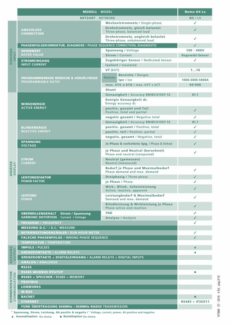
MODELL MODEL Nemo D4 Le
NETZART NETWORK NS / LV
ANSCHLUSSCONNECTION
Wechselstromnetz / Single-phase 4
Drehstromnetz, gleich belastetThree-phase, balanced load 4
Drehstromnetz, ungleich belastetThree-phase, unbalanced load 4
PHASENFOLGEKORREKTUR, DIAGNOSE / PHASE SEQUENCE CORRECTION, DIAGNOSTIC 4
NENNWERTRATED VALUE
Spannung / Voltage 100 - 400V
Strom / Current Rogowski-Sensor
STROMEINGANGINPUT CURRENT
Zugehöriger Sensor / Dedicated Sensor 4
Isoliert / Insulated
PROGRAMMIERBARE BEREICHE & VERHÄLTNISSEPROGRAMMABLE RATIO
VT (kVT) 1...10
SensorBereiche / Ranges
Ipn / Isn 1000-3000-5000A
max. kTV x kTA / max. kVT x kCT 99’990
Shunt
WIRKENERGIEACTIVE ENERGY
Genauigkeit / Accuracy EN/IEC 61557-12 Kl.1
Energie Genauigkeit dcEnergy accuracy dc
positiv, gesamt und TeilPositive, total and partial 4
negativ gesamt / Negative total 4
BLINDENERGIEREACTIVE ENERGY
Genauigkeit / Accuracy EN/IEC 61557-12 Kl.1
positiv, gesamt / Positive, total 4
positiv, teil / Positive, partial 4
negativ, gesamt / Negative, total 4
SPANNUNGVOLTAGE
Je Phase & verkettete Spg. / Phase & linked 4
STROMCURRENT
je Phase und Neutral (berechnet)Phase and neutral (computed) 4
Neutral (gemessen)Neutral (measured)
Bedarf je Phase und Maximalbedarf Phase demand and max. demand 4
LEISTUNGSFAKTORPOWER FACTOR
Dreiphasig / Three-phase 4
je Phase / Phase 4
LEISTUNGPOWER
Wirk-, Blind-, ScheinleistungActive, reactive, apparent 4
Leistungbedarf & MaximalbedarfDemand and max. demand 4
Blindleistung & Wirkleistung je PhasePhase active and reactive 4
OBERWELLENGEHALT Strom / SpannungHARMONIC DISTORTION Current / Voltage
THD 4
Analyse / Analysis 4
FREQUENZ / FREQUENCY 4
MESSUNG D.C.1 / D.C.1 MEASURE
BETRIEBSSTUNDENZÄHLER / RUN HOUR METER 4
FALSCHE PHASENFOLGE / WRONG PHASE SEQUENCE 4
TEMPERATUR / TEMPERATURE
IMPULS / PULSES ♦GRENZKONTAKTE / ALARM RELAYS ♦GRENZKONTAKTE + DIGITALEINGANG / ALARM RELAYS + DIGITAL INPUTS
ANALOG / ANALOGUE
RS232
RS485 MODBUS RTU/TCP ●RS485 + SPEICHER / RS485 + MEMORY
PROFIBUS
LONWORKS
M-BUS
BACNET ●ETHERNET RS485 + IF2E011
FUNK ÜBERTRAGUNG 868MHz / 868MHz RADIO TRANSMISSION
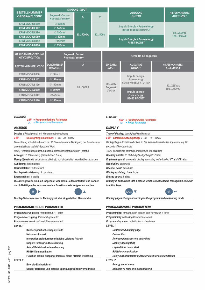
ANZEIGE
Display : Flüssigkristall mit Hintergrundbeleuchtung
Backlighting einstellbar: 0 - 35 - 70 - 100%
Beleuchtung schaltet sich nach ca. 20 Sekunden ohne Betätigung der Fronttastatur
automatisch ab (auf definierbaren Wert)
100%-Hintergrundbeleuchtung nach erstmaliger Betätigung der Tastatur
Anzeige: 10.000 4-stellig (Ziffernhöhe 12 mm)
Messgröβeneinheit: automatisch, abhängig von eingestellten Wandlerubersetzungen
Auflösung: automatisch
Dezimalstellen: automatisch
Display-Aktualisierung: 1 Update/s
Energiezähler: 8-stellig
Die Anzeigewerte sind auf insgesamt vier Menu-Seiten unterteilt und können
durch Betätigen der entsprechenden Funktionstaste aufgerufen werden.
Display-Seitenwechsel in Abhängigkeit des eingestellten Messmodus
PROGRAMMIERBARE PARAMETER
Programmierung: über Fronttastatur, 4 Tasten
Programmierzugang: Passwort-geschützt
Programmiermenü: auf zwei Ebenen unterteilt
LEVEL 1
Kundenspezifische Display-Seite
Netzanschlussart
Integrationszeit durchschnittliche Leistung / Strom
Display-Hintergrundbeleuchtung
Anlauf Betriebsstundenerfassung
RS485-Kommunikation
Funktion Relais-Ausgang: Impuls / Alarm / Relais-Switching
LEVEL 2
Energie-Zählverfahren
Sensor-Bereiche und externe Spannungswandlerverhältnisse
DISPLAY
Type of display: backlighted liquid crystal
Selectable backlighting: 0 – 35 – 70 – 100%
Backlighting automatic reduction (to the selected value) after approximately 20
seconds of keyboard idle
100% backlighting after first pressure on the keyboard
Reading points: 10.000 4 digits (digit height 12mm)
Engineering unit: automatic display according to the loaded VT and CT ratios
Resolution: automatic
Decimal point: automatic
Display updating: 1 reading/s
Energy count: 8 digits
Display is subdivided into 4 menus which are accessible through the relevant
function keys:
Display pages change according to the programmed measuring mode
PROGRAMMABLE PARAMETERS
Programming: through touch-screen front keyboard, 4 keys
Programming access: password-protected
Programming menu: subdivided on two levels
LEVEL 1
Customized display page
Connection
Average power/current delay time
Display backlighting
Lapsed time count start
RS485 communication
Relay output function pulses or alarm or state switching
LEVEL 2
Energy count mode
External VT ratio and current rating
NT8
89
07 -
2016
4
Ed.
pag.
3/10
u i pqs etu i pqs etu i pqs etu i pqs et
LEGENDE: = Programmierbare Parameter= Rücksetzbare Parameter
LEGEND:= Programmable Parameter= Reset Parameter
BESTELLNUMMER ORDERING CODE
EINGANG INPUTAUSGANGOUTPUT
HILFSSPANNUNGAUX.SUPPLYRogowski-Sensor
Rogowski sensorA V
KRNEMOD4LE080 ∅ 80mm
20...5000A 80...500V
Impuls Energie / Pulse energyRS485 ModBus RTU/TCP
80...265Vac100...300Vdc
KRNEMOD4LE142 ∅ 142mm
KRNEMOD4LE190 ∅ 190mm
KRNEMOD4LB080 ∅ 80mmImpuls Energie / Pulse energy
RS485 BACNETKRNEMOD4LB142 ∅142mm
KRNEMOD4LB190 ∅ 190mm
KIT ZUSAMMENSETZUNGKIT COMPOSITION
Rogowski SensorRogowski sensor
Nemo D4-Le RogowskiRetrofit
BESTELLNUMMER CODEDURCHMESSER
DIAMETERA EINGANG
INPUTAUSGANGOUTPUT
HILFSSPANNUNG.AUX.SUPPLY
KRNEMOD4LE080 ∅ 80mm
20...5000A80...500VRogowski
Sensor
Impuls EnergiePulse energy
RS485 ModBus RTU/TCP80...265Vac100...300Vdc
KRNEMOD4LE142 ∅ 142mm
KRNEMOD4LE190 ∅ 190mm
KRNEMOD4LB080 ∅ 80mmImpuls EnergiePulse energyRS485 BACNET
KRNEMOD4LB142 ∅142mm
KRNEMOD4LB190 ∅ 190mm
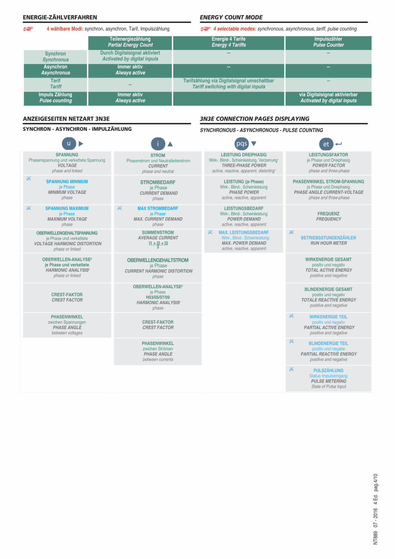
ENERGY COUNT MODE
4 selectable modes: synchronous, asynchronous, tariff, pulse counting
3N3E CONNECTION PAGES DISPLAYING
SYNCHRONOUS - ASYNCHRONOUS - PULSE COUNTING
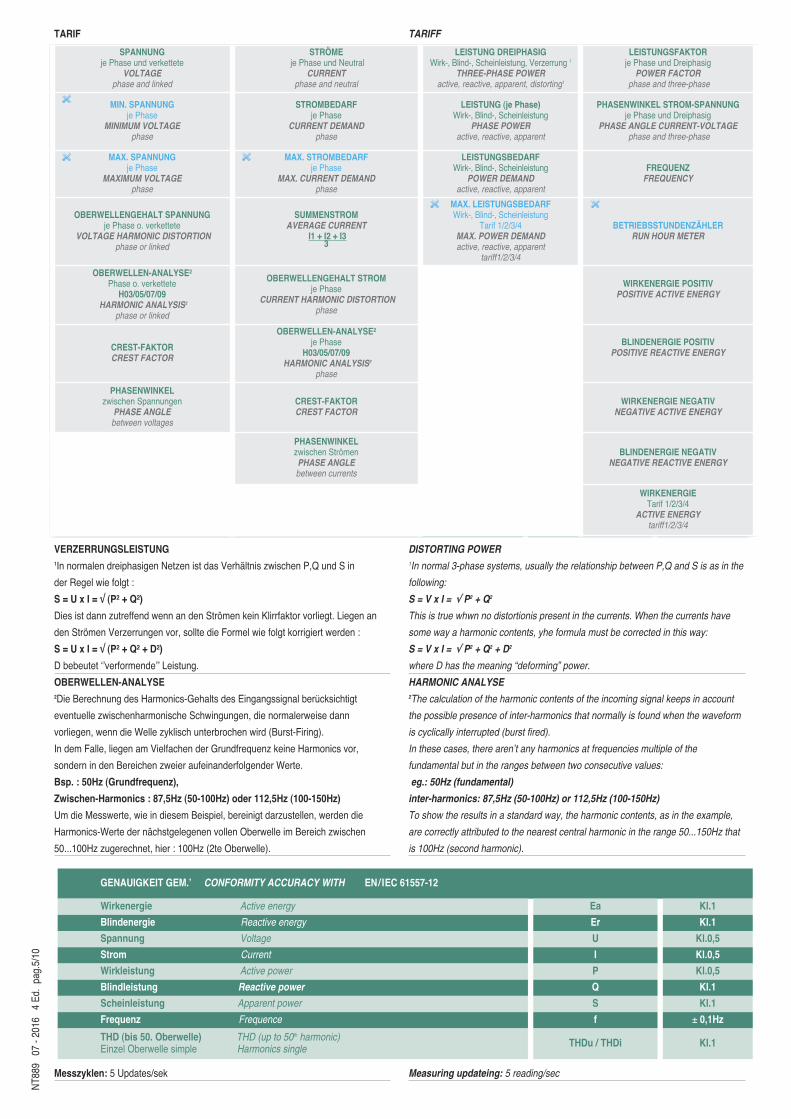
ENERGIE-ZÄHLVERFAHREN
4 wählbare Modi: synchron, asynchron, Tarif, Impulszählung
ANZEIGESEITEN NETZART 3N3E
SYNCHRON - ASYNCHRON - IMPULZÄHLUNG
SPANNUNGPhasenspannung und verkettete Spannung
VOLTAGEphase and linked
STROMPhasenstrom und Neutralleiterstrom
CURRENTphase and neutral
LEISTUNG DREIPHASIGWirk-, Blind-, Scheinleistung, Verzerrung1
THREE-PHASE POWER active, reactive, apparent, distorting1
LEISTUNGSFAKTORje Phase und DreiphasigPOWER FACTOR
phase and three-phase
SPANNUNG MINIMUMje Phase
MINIMUM VOLTAGEphase
STROMBEDARFje Phase
CURRENT DEMANDphase
LEISTUNG (je Phase)Wirk-, Blind-, Scheinleistung
PHASE POWER active, reactive, apparent
PHASENWINKEL STROM-SPANNUNGje Phase und Dreiphasig
PHASE ANGLE CURRENT-VOLTAGEphase and three-phase
SPANNUNG MAXIMUMje Phase
MAXIMUM VOLTAGEphase
MAX STROMBEDARFje Phase
MAX. CURRENT DEMANDphase
LEISTUNGSBEDARFWirk-, Blind-, Scheinleistung
POWER DEMANDactive, reactive, apparent
FREQUENZFREQUENCY
OBERWELLENGEHALTSPANNUNGje Phase und verkettete
VOLTAGE HARMONIC DISTORTIONphase or linked
SUMMENSTROMAVERAGE CURRENT
I1 + I2 + I33
MAX. LEISTUNGSBEDARFWirk-, Blind-, ScheinleistungMAX. POWER DEMANDactive, reactive, apparent
BETRIEBSSTUNDENZÄHLERRUN HOUR METER
OBERWELLEN-ANALYSE²je Phase und verketteteHARMONIC ANALYSIS2
phase or linked
OBERWELLENGEHALTSTROMje Phase
CURRENT HARMONIC DISTORTIONphase
WIRKENERGIE GESAMTpositiv und negativ
TOTAL ACTIVE ENERGYpositive and negative
CREST-FAKTORCREST FACTOR
OBERWELLEN-ANALYSE²je Phase
H03/05/07/09HARMONIC ANALYSIS2
phase
BLINDENERGIE GESAMTpositiv und negativ
TOTALE REACTIVE ENERGYpositive and negative
PHASENWINKEL zwichen SpannungenPHASE ANGLE between voltages
CREST-FAKTORCREST FACTOR
WIRKENERGIE TEILpositiv und negativ
PARTIAL ACTIVE ENERGYpositive and negative
PHASENWINKEL zwichen StrömenPHASE ANGLE between currents
BLINDENERGIE TEILpositiv und negativ
PARTIAL REACTIVE ENERGYpositive and negative
PULSZÄHLUNGStatus ImpulseingangPULSE METERINGState of Pulse Input
NT8
89
07 -
2016
4
Ed.
pag.
4/10
u i pqs etu i pqs etu i pqs etu i pqs et
TeilenergiezählungPartial Energy Count
Energie 4 TarifeEnergy 4 Tariffs
ImpulszählerPulse Counter
SynchronSynchronus
Durch Digitalsignal aktiviertActivated by digital inpuls
-- --
AsynchronAsynchronus
Immer aktivAlways active
-- --
TarifTariff --
Tarifzählung via Digitalsignal umschaltbarTariff switching with digital inputs
--
Impuls ZählungPulse counting
Immer aktivAlways active
via Digitalsignal aktivierbarActivated by digital inputs
TARIF
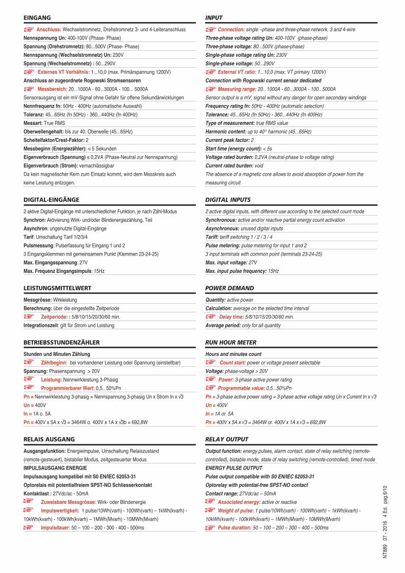
VERZERRUNGSLEISTUNG1In normalen dreiphasigen Netzen ist das Verhältnis zwischen P,Q und S in
der Regel wie folgt :
S = U x I = √ (P² + Q²)
Dies ist dann zutreffend wenn an den Strömen kein Klirrfaktor vorliegt. Liegen an
den Strömen Verzerrungen vor, sollte die Formel wie folgt korrigiert werden :
S = U x I = √ (P² + Q² + D²)
D bebeutet ‘’verformende’’ Leistung.
OBERWELLEN-ANALYSE2Die Berechnung des Harmonics-Gehalts des Eingangssignal berucksichtigt
eventuelle zwischenharmonische Schwingungen, die normalerweise dann
vorliegen, wenn die Welle zyklisch unterbrochen wird (Burst-Firing).
In dem Falle, liegen am Vielfachen der Grundfrequenz keine Harmonics vor,
sondern in den Bereichen zweier aufeinanderfolgender Werte.
Bsp. : 50Hz (Grundfrequenz),
Zwischen-Harmonics : 87,5Hz (50-100Hz) oder 112,5Hz (100-150Hz)
Um die Messwerte, wie in diesem Beispiel, bereinigt darzustellen, werden die
Harmonics-Werte der nächstgelegenen vollen Oberwelle im Bereich zwischen
50...100Hz zugerechnet, hier : 100Hz (2te Oberwelle).
Messzyklen: 5 Updates/sek
TARIFF
DISTORTING POWER1In normal 3-phase systems, usually the relationship between P,Q and S is as in the
following:
S = V x I = √ P2 + Q2
This is true whwn no distortionis present in the currents. When the currents have
some way a harmonic contents, yhe formula must be corrected in this way:
S = V x I = √ P2 + Q2 + D2
where D has the meaning “deforming” power.
HARMONIC ANALYSE2The calculation of the harmonic contents of the incoming signal keeps in account
the possible presence of inter-harmonics that normally is found when the waveform
is cyclically interrupted (burst fired).
In these cases, there aren’t any harmonics at frequencies multiple of the
fundamental but in the ranges between two consecutive values:
eg.: 50Hz (fundamental)
inter-harmonics: 87,5Hz (50-100Hz) or 112,5Hz (100-150Hz)
To show the results in a standard way, the harmonic contents, as in the example,
are correctly attributed to the nearest central harmonic in the range 50...150Hz that
is 100Hz (second harmonic).
Measuring updateing: 5 reading/sec
NT8
89
07 -
2016
4
Ed.
pag.
5/10
SPANNUNGje Phase und verkettete
VOLTAGEphase and linked
STRÖME je Phase und Neutral
CURRENTphase and neutral
LEISTUNG DREIPHASIGWirk-, Blind-, Scheinleistung, Verzerrung 1
THREE-PHASE POWER active, reactive, apparent, distorting1
LEISTUNGSFAKTORje Phase und DreiphasigPOWER FACTOR
phase and three-phase
MIN. SPANNUNGje Phase
MINIMUM VOLTAGEphase
STROMBEDARFje Phase
CURRENT DEMANDphase
LEISTUNG (je Phase)Wirk-, Blind-, Scheinleistung
PHASE POWER active, reactive, apparent
PHASENWINKEL STROM-SPANNUNGje Phase und Dreiphasig
PHASE ANGLE CURRENT-VOLTAGEphase and three-phase
MAX. SPANNUNGje Phase
MAXIMUM VOLTAGEphase
MAX. STROMBEDARFje Phase
MAX. CURRENT DEMANDphase
LEISTUNGSBEDARFWirk-, Blind-, Scheinleistung
POWER DEMANDactive, reactive, apparent
FREQUENZFREQUENCY
OBERWELLENGEHALT SPANNUNGje Phase o. verkettete
VOLTAGE HARMONIC DISTORTIONphase or linked
SUMMENSTROMAVERAGE CURRENT
I1 + I2 + I33
MAX. LEISTUNGSBEDARFWirk-, Blind-, Scheinleistung
Tarif 1/2/3/4MAX. POWER DEMANDactive, reactive, apparent
tariff1/2/3/4
BETRIEBSSTUNDENZÄHLERRUN HOUR METER
OBERWELLEN-ANALYSE²Phase o. verkettete
H03/05/07/09HARMONIC ANALYSIS2
phase or linked
OBERWELLENGEHALT STROMje Phase
CURRENT HARMONIC DISTORTIONphase
WIRKENERGIE POSITIVPOSITIVE ACTIVE ENERGY
CREST-FAKTORCREST FACTOR
OBERWELLEN-ANALYSE²je Phase
H03/05/07/09HARMONIC ANALYSIS2
phase
BLINDENERGIE POSITIVPOSITIVE REACTIVE ENERGY
PHASENWINKEL zwischen SpannungenPHASE ANGLE between voltages
CREST-FAKTORCREST FACTOR
WIRKENERGIE NEGATIVNEGATIVE ACTIVE ENERGY
PHASENWINKELzwischen StrömenPHASE ANGLE between currents
BLINDENERGIE NEGATIVNEGATIVE REACTIVE ENERGY
WIRKENERGIETarif 1/2/3/4
ACTIVE ENERGYtariff1/2/3/4
GENAUIGKEIT GEM.’ CONFORMITY ACCURACY WITH EN/IEC 61557-12
Wirkenergie Active energy Ea Kl.1
Blindenergie Reactive energy Er Kl.1
Spannung Voltage U Kl.0,5
Strom Current I Kl.0,5
Wirkleistung Active power P Kl.0,5
Blindleistung Reactive power Q Kl.1
Scheinleistung Apparent power S Kl.1
Frequenz Frequence f ± 0,1Hz
THD (bis 50. Oberwelle) THD (up to 50th harmonic)Einzel Oberwelle simple Harmonics single THDu / THDi Kl.1
NT8
89
07 -
2016
4
Ed.
pag.
6/10
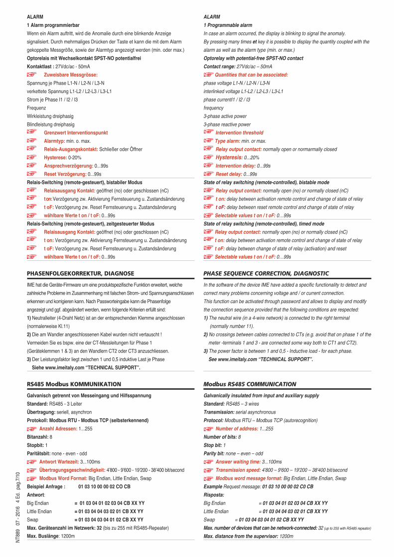
INPUT
Connection: single –phase and three-phase network, 3 and 4-wire
Three-phase voltage rating Un: 400-100V (phase-phase)
Three-phase voltage: 80...500V (phase-phase)
Single-phase voltage rating Un: 230V
Single-phase voltage: 50...290V
External VT ratio: 1...10,0 (max. VT primary 1200V)
Connection with Rogowski current sensor dedicated
Measuring range: 20...1000A - 60...3000A - 100...5000A
Sensor output is a mV, signal without any danger for open secondary windings
Frequency rating fn: 50Hz - 400Hz (automatic selection)
Tolerance: 45...65Hz (fn 50Hz) - 360...440Hz (fn 400Hz)
Type of measurement: true RMS value
Harmonic content: up to 40 th harmonic (45...65Hz)
Current peak factor: 2
Start time (energy count): < 5s
Voltage rated burden: 0,2VA (neutral-phase to voltage rating)
Current rated burden: void
The absence of a magnetic core allows to avoid absorption of power from the
measuring circuit
DIGITAL INPUTS
2 active digital inputs, with different use according to the selected count mode
Synchronous: active and/or reactive partial energy count activation
Asynchronous: unused digital inputs
Tariff: tariff switching 1 / 2 / 3 / 4
Pulse metering: pulse metering for input 1 and 2
3 input terminals with common point (terminals 23-24-25)
Max. input voltage: 27V
Max. input pulse frequency: 15Hz
POWER DEMAND
Quantity: active power
Calculation: average on the selected time interval
Delay time: 5/8/10/15/20/30/60 min.
Average period: only for all quantity
RUN HOUR METER
Hours and minutes count
Count start: power or voltage present selectable
Voltage: phase-voltage > 20V
Power: 3-phase active power rating
Programmable value: 0,5...50%Pn
Pn = 3-phase active power rating = 3-phase active voltage rating Un x Current In x √3
Un = 400V
In = 1A or. 5A
Pn = 400V x 5A x √3 = 3464W or. 400V x 1A x √3 = 692,8W
RELAY OUTPUT
Output function: energy pulses, alarm contact, state of relay switching (remote-
controlled), bistable mode, state of relay switching (remote-controlled), timed mode
ENERGY PULSE OUTPUT
Pulse output compatible with S0 EN/IEC 62053-31
Optorelay with potential-free SPST-NO contact
Contact range: 27Vdc/ac – 50mA
Associated energy: active or reactive
Weight of pulse: 1 pulse/10Wh(varh) - 100Wh(varh) – 1kWh(kvarh) -
10kWh(kvarh) - 100kWh(kvarh) – 1MWh(Mvarh) - 10MWh(Mvarh)
Pulse duration: 50 – 100 – 200 – 300 – 400 – 500ms
EINGANG
Anschluss: Wechselstromnetz, Drehstromnetz 3- und 4-Leiteranschluss
Nennspannung Un: 400-100V (Phase- Phase)
Spannung (Drehstromnetz): 80...500V (Phase- Phase)
Nennspannung (Wechselstromnetz) Un: 230V
Spannung (Wechselstromnetz) : 50...290V
Externes VT Verhältnis: 1...10,0 (max. Primärspannung 1200V)
Anschluss an zugeordnete Rogowski Stromsensoren
Messbereich: 20...1000A - 60...3000A - 100... 5000A
Sensorausgang ist ein mV-Signal ohne Gefahr für offene Sekundärwicklungen
Nennfrequenz fn: 50Hz - 400Hz (automatische Auswahl)
Toleranz: 45...65Hz (fn 50Hz) - 360...440Hz (fn 400Hz)
Messart: True RMS
Oberwellengehalt: bis zur 40. Oberwelle (45...65Hz)
Scheitelfaktor/Crest-Faktor: 2
Messbeginn (Energiezähler): < 5 Sekunden
Eigenverbrauch (Spannung) ≤ 0,2VA (Phase-Neutral zur Nennspannung)
Eigenverbrauch (Strom): vernachlässigbar
Da kein magnetischer Kern zum Einsatz kommt, wird dem Messkreis auch
keine Leistung entzogen.
DIGITAL-EINGÄNGE
2 aktive Digital-Eingänge mit unterschiedlicher Funktion, je nach Zähl-Modus
Synchron: Aktivierung Wirk- und/oder Blindenergiezählung, Teil
Asynchron: ungenutzte Digital-Eingänge
Tarif: Umschaltung Tarif 1/2/3/4
Pulsmessung: Pulserfassung fur Eingang 1 und 2
3 Eingangsklemmen mit gemeinsamem Punkt (Klemmen 23-24-25)
Max. Eingangsspannung: 27V
Max. Frequenz Eingangsimpuls: 15Hz
LEISTUNGSMITTELWERT
Messgrösse: Wirkleistung
Berechnung: über die eingestellte Zeitperiode
Zeitperiode: : 5/8/10/15/20/30/60 min.
Integrationszeit: gilt für Strom und Leistung
BETRIEBSSTUNDENZÄHLER
Stunden und Minuten Zählung
Zählbeginn: bei vorhandener Leistung oder Spannung (einstellbar)
Spannung: Phasenspannung > 20V
Leistung: Nennwirkleistung 3-Phasig
Programmierbarer Wert: 0,5...50%Pn
Pn = Nennwirkleistung 3-phasig = Nennspannung 3-phasig Un x Strom In x √3
Un = 400V
In = 1A o. 5A
Pn = 400V x 5A x √3 = 3464W o. 400V x 1A x √3b = 692,8W
RELAIS AUSGANG
Ausgangsfunktion: Energieimpulse, Umschaltung Relaiszustand
(remote-gesteuert), bistabiler Modus, zeitgesteuerter Modus
IMPULSAUSGANG ENERGIE
Impulsausgang kompatibel mit S0 EN/IEC 62053-31
Optorelais mit potentialfreiem SPST-NO Schliesserkontakt
Kontaktlast : 27Vdc/ac - 50mA
Zuweisbare Messgrösse: Wirk- oder Blindenergie
Impulswertigkeit: 1 pulse/10Wh(varh) - 100Wh(varh) – 1kWh(kvarh) -
10kWh(kvarh) - 100kWh(kvarh) – 1MWh(Mvarh) - 10MWh(Mvarh)
Impulsdauer: 50 – 100 – 200 - 300 - 400 - 500ms
NT8
89
07 -
2016
4
Ed.
pag.
7/10
ALARM
1 Alarm programmierbar
Wenn ein Alarm auftritt, wird die Anomalie durch eine blinkende Anzeige
signalisiert. Durch mehrmaliges Drucken der Taste et kann die mit dem Alarm
gekoppelte Messgröße, sowie der Alarmtyp angezeigt werden (min. oder max.)
Optorelais mit Wechselkontakt SPST-NO potentialfrei
Kontaktlast : 27Vdc/ac - 50mA
Zuweisbare Messgrösse:
Spannung je Phase L1-N / L2-N / L3-N
verkettete Spannung L1-L2 / L2-L3 / L3-L1
Strom je Phase I1 / I2 / I3
Frequenz
Wirkleistung dreiphasig
Blindleistung dreiphasig
Grenzwert Interventionspunkt
Alarmtyp: min. o. max.
Relais-Ausgangskontakt: Schließer oder Öffner
Hysterese: 0-20%
Ansprechverzögerung: 0...99s
Reset Verzögerung: 0...99s
Relais-Switching (remote-gesteuert), bistabiler Modus
Relaisausgang Kontakt: geöffnet (no) oder geschlossen (nC)
t on: Verzögerung zw. Aktivierung Fernsteuerung u. Zustandsänderung
t oF: Verzögerung zw. Reset Fernsteuerung u. Zustandsänderung
wählbare Werte t on / t oF: 0...99s
Relais-Switching (remote-gesteuert), zeitgesteuerter Modus
Relaisausgang Kontakt: geöffnet (no) oder geschlossen (nC)
t on: Verzögerung zw. Aktivierung Fernsteuerung u. Zustandsänderung
t oF: Verzögerung zw. Reset Fernsteuerung u. Zustandsänderung
wählbare Werte t on / t oF: 0...99s
PHASENFOLGEKORREKTUR, DIAGNOSE
IME hat die Geräte-Firmware um eine produktspezifische Funktion erweitert, welche
zahlreiche Probleme im Zusammenhang mit falschen Strom- und Spannungsanschlussen
erkennen und korrigieren kann. Nach Passworteingabe kann die Phasenfolge
angezeigt und ggf. abgeändert werden, wenn folgende Kriterien erfullt sind:
1) Neutralleiter (4-Draht Netz) ist an der entsprechenden Klemme angeschlossen
(normalerweise Kl.11)
2) Die am Wandler angeschlossenen Kabel wurden nicht vertauscht !
Vermeiden Sie es bspw. eine der CT-Messleitungen fur Phase 1
(Geräteklemmen 1 & 3) an den Wandlern CT2 oder CT3 anzuschliessen.
3) Der Leistungsfaktor liegt zwischen 1 und 0,5 induktive Last je Phase
Siehe www.imeitaly.com “TECHNICAL SUPPORT”.
RS485 Modbus KOMMUNIKATION
Galvanisch getrennt von Messeingang und Hilfsspannung
Standard: RS485 - 3 Leiter
Übertragung: seriell, asynchron
Protokoll: Modbus RTU - Modbus TCP (selbsterkennend)
Anzahl Adressen: 1...255
Bitanzahl: 8
Stopbit: 1
Paritätsbit: none - even - odd
Antwort Wartezeit: 3...100ms
Übertragungsgeschwindigkeit: 4’800 - 9’600 - 19’200 - 38’400 bit/second
Modbus Word Format: Big Endian, Little Endian, Swap
Beispiel Anfrage : 01 03 10 00 00 02 CO CB
Antwort:
Big Endian = 01 03 04 01 02 03 04 CB XX YY
Little Endian = 01 03 04 04 03 02 01 CB XX YY
Swap = 01 03 04 03 04 01 02 CB XX YY
Max. Geräteanzahl im Netzwerk: 32 (bis zu 255 mit RS485-Repeater)
Max. Buslänge: 1200m
ALARM
1 Programmable alarm
In case an alarm occurred, the display is blinking to signal the anomaly.
By pressing many times et key it is possible to display the quantity coupled with the
alarm as well as the alarm type (min. or max.)
Optorelay with potential-free SPST-NO contact
Contact range: 27Vdc/ac – 50mA
Quantities that can be associated:
phase voltage L1-N / L2-N / L3-N
interlinked voltage L1-L2 / L2-L3 / L3-L1
phase currentI1 / I2 / I3
frequency
3-phase active power
3-phase reactive power
Intervention threshold
Type alarm: min. or max.
Relay output contact: normally open or normarmally closed
Hysteresis: 0...20%Intervention delay: 0...99s
Reset delay: 0...99s
State of relay switching (remote-controlled), bistable mode
Relay output contact: normally open (no) or normally closed (nC)
t on: delay between activation remote control and change of state of relay
t oF: delay between reset remote control and change of state of relay
Selectable values t on / t oF: 0…99s
State of relay switching (remote-controlled), timed mode
Relay output contact: normally open (no) or normally closed (nC)
t on: delay between activation remote control and change of state of relay
t oF: delay between change of state of relay (activation) and reset
Selectable values t on / t oF: 0…99s
PHASE SEQUENCE CORRECTION, DIAGNOSTIC
In the software of the device IME have added a specific functionality to detect and
correct many problems concerning voltage and / or current connection.
This function can be activated through password and allows to display and modify
the connection sequence provided that the following conditions are respected:
1) The neutral wire (in a 4-wire network) is connected to the right terminal
(normally number 11).
2) No crossings between cables connected to CTs (e.g. avoid that on phase 1 of the
meter -terminals 1 and 3 - are connected some way both to CT1 and CT2).
3) The power factor is between 1 and 0,5 - Inductive load - for each phase.
See www.imeitaly.com “TECHNICAL SUPPORT”.
Modbus RS485 COMMUNICATION
Galvanically insulated from input and auxiliary supply
Standard: RS485 – 3 wires
Transmission: serial asynchronous
Protocol: Modbus RTU – Modbus TCP (autorecognition)
Number of address: 1...255
Number of bits: 8
Stop bit: 1
Parity bit: none – even – odd
Answer waiting time: 3...100ms
Transmission speed: 4'800 – 9'600 – 19'200 – 38'400 bit/second
Modbus word message format: Big Endian, Little Endian, Swap
Example Request message: 01 03 10 00 00 02 C0 CB
Risposta:
Big Endian = 01 03 04 01 02 03 04 CB XX YY
Little Endian = 01 03 04 04 03 02 01 CB XX YY
Swap = 01 03 04 03 04 01 02 CB XX YY
Max. number of devices that can be network-connected: 32 (up to 255 with RS485 repeator)
Max. distance from the supervisor: 1200m
NT8
89
07 -
2016
4
Ed.
pag.
8/10
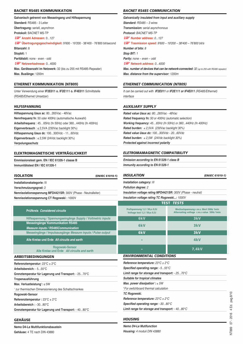
BACNET RS485 KOMMUNIKATION
Galvanisch getrennt von Messeingang und Hilfsspannung
Standard: RS485 - 3 Leiter
Übertragung: seriell, asynchron
Protokoll: BACNET MS-TP
Anzahl Adressen: 0...127
Übertragungsgeschwindigkeit: 9’600 - 19’200 - 38’400 - 76’800 bit/second
Bitanzahl: 8
Stopbit: 1
Paritätsbit: none - even - odd
Netzwerkadresse: 0...4000
Max. Geräteanzahl im Netzwerk: 32 (bis zu 255 mit RS485-Repeater)
Max. Buslänge: 1200m
ETHERNET KOMMUNIKATION (NT809)
Unter Verwendung einer IF2E011 o. IF2E111 o. IF4E011 Schnittstelle
(RS485/Ethernet Umsetzer)
HILFSSPANNUNG
Hilfsspannung Uaux ac: 80...265Vac - 48Vac
Nennfrequenz fn: 50 oder 400Hz (automatische Auswahl)
Arbeitsfrequenz : 45…65Hz (fn 50Hz) oder 360...440Hz (fn 400Hz)
Eigenverbrauch : ≤ 2,5VA (230Vac backlight 30%)
Hilfsspannung Uaux dc: 100...300Vdc - 11...60Vdc
Eigenverbrauch : ≤ 2,5W (24Vdc backlight 30%)
Verpolungsschutz
ELEKTROMAGNETISCHE VERTRÄGLICHKEIT
Emmissionstest gem. EN / IEC 61326-1 classe B
Immunitätstest EN / IEC 61326-1
ISOLATION (EN/IEC 61010-1)
Installationskategorie: III
Verschmutzungsgrad: 2
Nennisolationsspannung MFD4421SR: 300V (Phase - Neutralleiter)
Nennisolationsspannung CT Rogowski : 1000V
ARBEITSBEDINGUNGEN
Referenztemperatur: 23°C ± 2°C
Arbeitsbereich: - 5...55°C
Grenztemperatur fur Lagerung und Transport: - 25...70°C
Tropenausfuhrung
Max. Verlustleistung1: ≤ 5W1 zur thermischen Dimensionierung des Schaltschrankes
Rogowski-Sensor
Referenztemperatur : 23°C ± 2°C
Arbeitsbereich : -30...80°C
Grenztemperatur fur Lagerung und Transport: - 40...80°C
GEHÄUSE
Nemo D4-Le Multifunktionsbaustein
Gehäuse: 4 TE nach DIN 43880
BACNET RS485 COMMUNICATION
Galvanically insulated from input and auxiliary supply
Standard: RS485 – 3 wires
Transmission: serial asynchronous
Protocol: BACNET MS-TP
Number address: 0...127
Trasmission speed: 9'600 – 19'200 – 38'400 – 76’800 bit/s
Number of bits: 8
Stop BIT: 1
Parity: none – even – odd
Network address: 0...4000
Max. number of devices that can be network-connected: 32 (up to 255 with RS485 repeator)
Max. distance from the supervisor: 1200m
ETHERNET COMMUNICATION (NT809)
It can be carried out with IF2E011 or IF2E111 or IF4E011 (RS485/Ethernet)
interface
AUXILIARY SUPPLY
Rated value Uaux ac: 80...265Vac - 48Vac
Rated frequency fn: 50 or 400Hz (automatic selection)
Working frequency: 45…65Hz (fn 50Hz) or 360...440Hz (fn 400Hz)
Rated burden: ≤ 2,5VA (230Vac backlight 30%)
Rated value Uaux dc: 100...300Vdc - 20...60Vdc
Rated burden: ≤ 2,5W (24Vdc backlight 30%)
Protected against incorrect polarity
ELETROMAMAGNETIC COMPATIBILITY
Emission according to EN 61326-1 class B
Immunity according to EN 61326-1
INSULATION (EN/IEC 61010-1)
Installation category: III
Pollution degree: 2
Insulation voltage rating MFD4421SR: 300V (Phase - neutral)
Insulation voltage rating TC Rogowski...: 1000V
ENVIRONMENTAL CONDITIONS
Reference temperature: 23°C ± 2°C
Specified operating range: -5...55°C
Limit range for storage and transport: - 25...70°C
Suitable for tropical climates
Max. power dissipation 1: ≤ 5W1For switchboard thermal calculation
TC Rogowski.
Reference temperature: 23°C ± 2°C
Specified operating range: -30...80°C
Limit range for storage and transport: - 40...80°C
HOUSING
Nemo D4-Le Mutifunction
Housing: 4 moduli DIN 43880
TEST TESTS
Prüfkreis Considered circuits Prufspannung 1,2 / 50μs 0,5JVoltage test 1,2 / 50μs 0,5J
Wechselspannung r.m.s. Wert 50Hz 1minAlternating voltage r.m.s value 50Hz 1min
Hilfsspannung / Spannungseingänge Supply / Voltmetric inputs 6kV 3kVMesseingänge/ Kommunikation RS485
Measure inputs / RS485Communication6kV 3kV
Messeingänge / Impulsausgänge Mesaure inputs / Pulse output 6kV 3kV
Alle Kreise und Erde All circuits and earth - 4kV
Rogowski-Sensor Alle Kreise und Erde All circuits and earth - 7,4kV
2 5 8 111 3 6 94 7
a
A
b
BL
N LOADX
2 11
INPUT
VOLTAGE CURRENT
15 29 20
AUX.SUPPLY
21+ –
33 34 35
RS 485
Rx / Tx GND + E1 E2 –
F
25 23 24
DIGITAL INPUT
C
W B
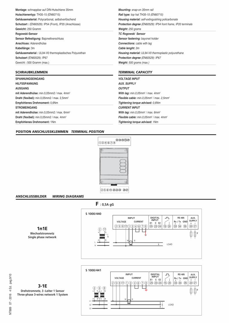
ANSCHLUSSBILDER WIRING DIAGRAMS
X
XX
a
A
b
B
a
A
b
BL1
L2
L3
LOAD
2 5 8
INPUT
VOLTAGE CURRENT
2 5 8 1 3 6 94 711 15 29 33 34 35
RS 485
Rx / Tx GND + E1 E2 –
25 23 24
DIGITAL INPUT
C20
AUX.SUPPLY
21+ –
F
W B
S 1000/441
S 1000/440
3-1EDrehstromnetz, 3 -Leiter 1 Sensor
Three-phase 3-wires network 1 System
NT8
89
07 -
2016
4
Ed.
pag.
9/10
1n1EWechselstromnetz
Single phase network
F : 0,5A gG
POSITION ANSCHLUSSKLEMMEN TERMINAL POSITION
6 71 3 435 15
933 34
20 212 5 8
29
11 25 23 24
Montage: schnappbar auf DIN-Hutschiene 35mm
Hutschienentyp: TH35-15 (EN60715)
Gehäusematerial: Polycarbonat, selbstverlöschend
Schutzart : (EN60529): IP54 (Front), IP20 (Anschlusse)
Gewicht: 250 Gramm
Rogowski-Sensor
Sensor Befestigung: Bajonettverschluss
Anschluss: Aderendhulse
Kabellänge: 3m
Gehäusematerial : UL94-V0 thermoplastisches Polyurethan
Schutzart (EN60529): IP67
Gewicht : 500 Gramm (max.)
SCHRAUBKLEMMEN
SPANNUNGSEINGANG
HILFSSPANNUNG
AUSGANG
mit Aderendhulse: min.0,05mm2 / max. 4mm2
Draht (flexibel): min.0,05mm2 / max. 2,5mm2
Empfohlenes Drehmoment: 0,6Nm
STROMEINGANG
mit Aderendhulse: min.0,05mm2 / max. 6mm2
Draht (flexibel): min.0,05mm2 / max. 4mm2
Empfohlenes Drehmoment: 1Nm
Mounting: snap-on 35mm rail
Rail type: top hat TH35-15 (EN60715)
Housing material: self-extinguishing policarbonate
Protection degree (EN60529): IP54 front frame, IP20 terminals
Weight: 250 grams
TC Rogowski Sensor
Sensor fastening: bayonet holder
Connections: cable with lag
Cable lenght: 3m
Housing material: UL94-V0 thermoplastic polyurethane
Protection degree (EN60529): IP67
Weight: 500 grams (max.)
TERMINAL CAPACITY
VOLTAGE INPUT
AUX. SUPPLY
OUTPUT
With lag: min.0,05mm2 / max. 4mm2
Flexible cable: min.0,05mm2 / max. 2,5mm2
Tightening torque advised: 0,6Nm
CURRENT INPUT
With lag: min.0,05mm2 / max. 6mm2
Flexible cable: min.0,05mm2 / max. 4mm2
Tightening torque advised: 1Nm
X
XX
a
AL1
L2
L3
NX X X
LOAD
INPUT
VOLTAGE CURRENT
2 5 8 1 3 6 94 711
2 5 8 11
15 29 33 34 35
RS 485
Rx / Tx GND + E1 E2 –
25 23 24
DIGITAL INPUT
C
20
AUX.SUPPLY
21+ –
F
W B
W B
W B
NT8
89
07 -
2016
4
Ed.
pag.
10/1
0IME Messgeräte behält sich das Recht vor, die technischen Merkmale ohne Benachrichtigung zu ändern
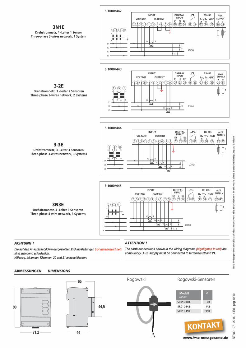
ABMESSUNGEN DIMENSIONS
3N3EDrehstromnetz, 4 -Leiter 3 Sensoren
Three-phase 4-wire network, 3 Systems
71,2
90
65
44,5
44
S 1000/445
ACHTUNG !
Die auf den Anschlussbildern dargestellten Erdungsleitungen (rot gekennzeichnet)sind zwingend erforderlich. Hilfsspg. ist an den Klemmen 20 und 21 anzuschliessen.
ATTENTION !
The earth connections shown in the wiring diagrams (highlighted in red) arecompulsory. Aux. supply must be connected to terminals 20 and 21.
Modell ∅Model
SR01D080 80
SR01D142 142
Rogowski Rogowski-Sensoren
SR01D190 190
www.ime-messgeraete.de
KONTAKT
X
XX
a
AL1
L2
L3
NX X X
LOAD
INPUT
VOLTAGE CURRENT
2 5 8 1 3 64 711
2 5 8 11
9 15 29 33 34 35
RS 485
Rx / Tx GND + E1 E2 –
25 23 24
DIGITAL INPUT
C
20
AUX.SUPPLY
21+ –
F
W B
X
XX
a
A
b
B
a
A
b
BL1
L2
L3
LOAD
2 5 8
INPUT
VOLTAGE CURRENT
2 5 8 1 3 6 94 711 15 29 33 34 35
RS 485
Rx / Tx GND + E1 E2 –
25 23 24
DIGITAL INPUT
C20
AUX.SUPPLY
21+ –
F
W B
W B
S 1000/443
S 1000/442
3N1EDrehstromnetz, 4 -Leiter 1 Sensor
Three-phase 3-wires network, 1 System
3-2EDrehstromnetz, 3 -Leiter 2 Sensoren
Three-phase 3-wires network, 2 Systems
X
XX
a
A
b
B
a
A
b
BL1
L2
L3
LOAD
2 5 8
INPUT
VOLTAGE CURRENT
2 5 8 1 3 6 94 711 15 29 33 34 35
RS 485
Rx / Tx GND + E1 E2 –
25 23 24
DIGITAL INPUT
C
20
AUX.SUPPLY
21+ –
F
W B
W B
W B
S 1000/444
3-3EDrehstromnetz, 3 -Leiter 3 Sensoren
Three-phase 3-wires network, 3 Systems